Embed Size (px)
Citation preview
DPM ®LANDMARK STRUCTURES ®
HO SCALE MODULAR BUILDING KIT3-IN-1 MODULAR KIT INDUSTRY/WAREHOUSE #35100
WOODLAND SCENICS® Manufactured by WOODLAND®
PO BOX 98, LINN CREEK, MO 65052 • N6 • woodlandscenics.com
The General Modular Instructions explain Modular construction techniques. The techniques apply to all Modular Kits. Refer to the General Instructions as often as necessary.
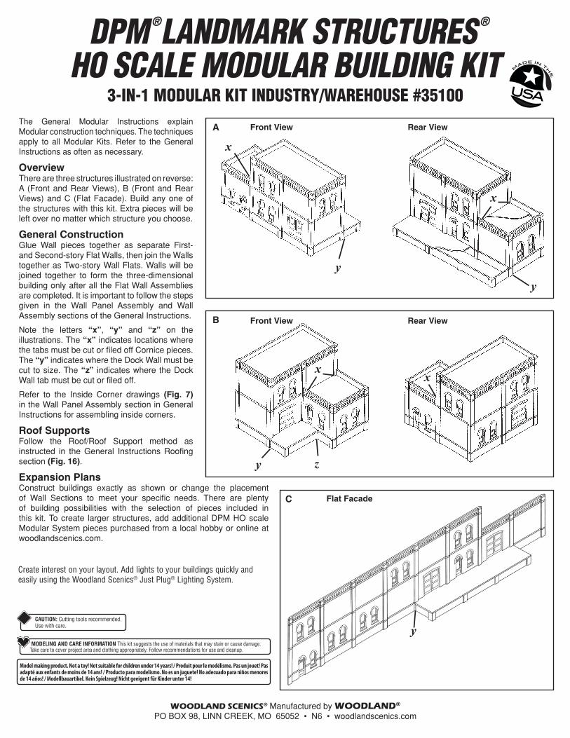
OverviewThere are three structures illustrated on reverse: A (Front and Rear Views), B (Front and Rear Views) and C (Flat Facade). Build any one of the structures with this kit. Extra pieces will be left over no matter which structure you choose.
General ConstructionGlue Wall pieces together as separate First- and Second-story Flat Walls, then join the Walls together as Two-story Wall Flats. Walls will be joined together to form the three-dimensional building only after all the Flat Wall Assemblies are completed. It is important to follow the steps given in the Wall Panel Assembly and Wall Assembly sections of the General Instructions.
Note the letters “x”, “y” and “z” on the illustrations. The “x” indicates locations where the tabs must be cut or filed off Cornice pieces. The “y” indicates where the Dock Wall must be cut to size. The “z” indicates where the Dock Wall tab must be cut or filed off.
Refer to the Inside Corner drawings (Fig. 7) in the Wall Panel Assembly section in General Instructions for assembling inside corners.
Roof SupportsFollow the Roof/Roof Support method as instructed in the General Instructions Roofing section (Fig. 16).
Expansion PlansConstruct buildings exactly as shown or change the placement of Wall Sections to meet your specific needs. There are plenty of building possibilities with the selection of pieces included in this kit. To create larger structures, add additional DPM HO scale Modular System pieces purchased from a local hobby or online at woodlandscenics.com.
Model making product. Not a toy! Not suitable for children under 14 years! / Produit pour le modélisme. Pas un jouet! Pas adapté aux enfants de moins de 14 ans! / Producto para modelismo. No es un juguete! No adecuado para niños menores de 14 años! / Modellbauartikel. Kein Spielzeug! Nicht geeigent für Kinder unter 14!
CAUTION: Cutting tools recommended. Use with care.
MODELING AND CARE INFORMATION This kit suggests the use of materials that may stain or cause damage. Take care to cover project area and clothing appropriately. Follow recommendations for use and cleanup.
Create interest on your layout. Add lights to your buildings quickly and easily using the Woodland Scenics® Just Plug® Lighting System.
A
x
yy
x
Front View Rear View
B
x
y z
x
Front View Rear View
C
y
Flat Facade
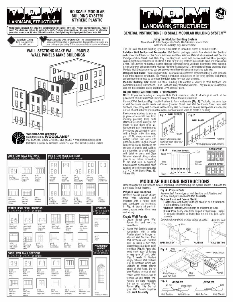
Using the Modular Building SystemMore than 40 Interchangeable Plastic Wall Sections make Walls.
Walls make Buildings any size or shape.The HO Scale Modular Building System is available as individual pieces or complete kits.Individual Wall Sections and Accessories: Wall Section packages contain four identical Wall Sections and connection Pilasters - plus Doors, Windows and Clear Window Material when needed. Wall Section Packages include Street Level, One-Story, Two-Story and Dock Level. Cornice and Dock Riser packages contain eight identical Sections. The Roof & Trim Kit (30190) contains materials to make and accessorize a roof. The Learning Kit (36000) teaches Modular techniques while you build a complete, small building. Create your own design using the Modular Planning Packet (30191). It contains full-sized drawings of all Modular Wall Sections so you can design your own three-dimensional mock-up buildings. Designer Bulk Packs: Each Designer Bulk Pack features a different architectural style with plans to build three specific structures. Everything is included to build one of the three options. Bulk Packs are an economical way to purchase Modular parts for your own designs.Modular Building Kits: These industrial building kits contain a variety of Wall Sections and complete building instructions - plus Roof and Clear Window Material. They are easy to assemble and can be expanded using additional DPM Modular parts.
BASIC MODULAR BUILDING INFORMATIONNOTE: If you are building a Designer Bulk Pack structure, refer to drawings in each kit for placement of individual Wall Sections as you follow these instructions.Connect Wall Sections (Fig. 1) with Pilasters to form wall panels (Fig. 2). Typically, the same type of Wall Section is used to create wall panels (connect Street Level Wall Sections to Street Level Wall Sections, One-Story Wall Sections to One-Story Wall Sections and so on). Wall panels are attached on top of each other to make entire walls. Connect entire walls to create a building. Pieces come attached to a sprue (a piece of resin left over from molding process). Keep parts attached to sprues until you are ready to use them (Fig. 3). Remove the part from the sprue by scoring the connection point with a hobby knife, then snap part off. Or, simply remove with cutting shears. Join parts with plastic cement or CA glue. Plastic cement works by dissolving the surface of plastic and welding parts together, so avoid contact with detail on parts and Clear Window Material. Always allow glue to set before proceeding to the next step. A squaring block assures right angles when sanding or forming corners. Use a 2" x 2" x 10" block (Figs. 12, 14 and 15).
MODULAR BUILDING INSTRUCTIONSRead through the instructions before beginning. Understanding the system makes it fun and the parts easy to put together.
Prepare Wall SectionsRemove excess plastic (flash) from Wall Sections and Pilasters with a hobby knife and sandpaper as instructed in Fig. 4. Wash all parts in warm, soapy water, then rinse and let dry.
Create Wall Panels1. Create Street Level Wall
Panels first and work up from there.
2. Attach Wall Sections together horizontally with a Wide Pilaster glued in flanges on adjacent Wall Sections. Keep Wall Sections and Pilasters level by using a 1/8" thick straightedge as a guide along top edges (Fig. 5). Apply glue along outer edge of flanges to keep glue off brick detail (Fig. 5 inset). Fit Pilasters snugly between Wall Sections (Fig. 6). Continue joining Wall Sections to create desired length of Wall Panel. Do not glue Pilasters to ends of WallPanels where corners will be formed. As you create Wall Panels, be sure Pilasters line up on adjacent Wall Panels (Fig. 13). Do not glue Wall Panels together until Wall Assembly.
GENERAL INSTRUCTIONS HO SCALE MODULAR BUILDING SYSTEMTM
Fig. 5
Fig. 6
Wall Section
GOOD FIT
Wide Pilaster
Brick DetailNo Gap
Wall Section
POOR FIT
Wide Pilaster
Gap
Straightedge at least 1/8" thick
Wide Pilaster
Wall Section
Wall Section
Glue
Flange
Fig. 3 DOOR SPRUE
WINDOW SPRUE
Cut
Wide Pilaster
PILASTER SPRUE
Narrow Pilaster
Cut
Sprue
Sprue
WALL PANEL
Three Assembled Wall Sections
Fig. 2
Flange
Flange: Recessed edge found on both sides of a wall section
Fig. 1 WALL SECTION
Pilasters
Fig. 4 - Prepare PartsRemove flash from edges of Wall Sections and Pilasters, but do NOT sand parts level until Wall Assembly.Remove Flash and Excess Plastic:
• Tabs: Score with hobby knife and snap off or cut with flush cutting shears. Sand flush.
• Nubs on Flange: Sand smooth so Pilasters lie flush.• Flash: Place hobby knife blade on part at slight angle. Scrape
in opposite direction so blade does not cut into part. Sand smooth.
Do not cut into detail or alter edges of parts.
Flash
Angle the blade and scrape
PILASTER
Tabs
WALL SECTIONNubs
WALL SECTION
HO SCALE MODULAR BUILDING SYSTEM STYRENE PLASTIC ®
WALL SECTIONS MAKE WALL PANELSWALL PANELS MAKE BUILDINGS
STREET LEVEL WALL SECTIONS2 11/16" w x 2 11/16" h (4 per pkg)
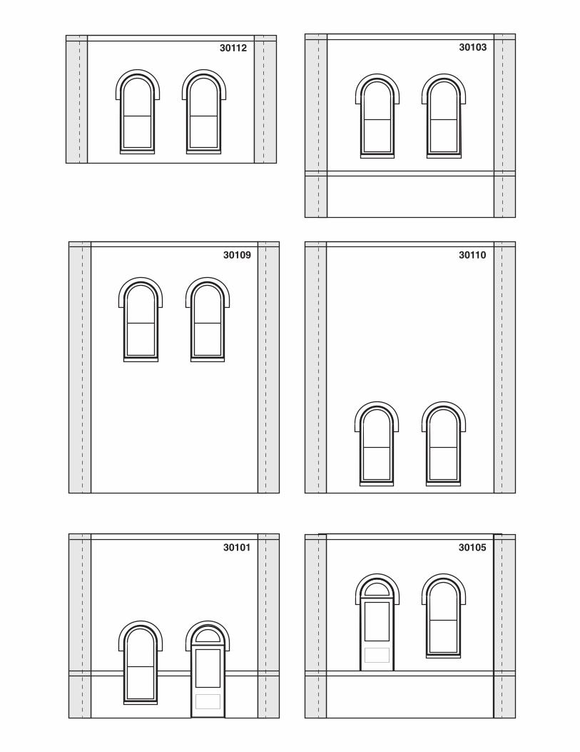
30101Street LevelArched Entry
30131Street LevelRectangular Entry
30134Street LevelRectangular Window
30141Street LevelVictorian Entry
30142Street LevelVictorian Window
30161Street Level20th Century Entry
30162Street Level20th Century Window
30171Street Level]Steel Sash Entry
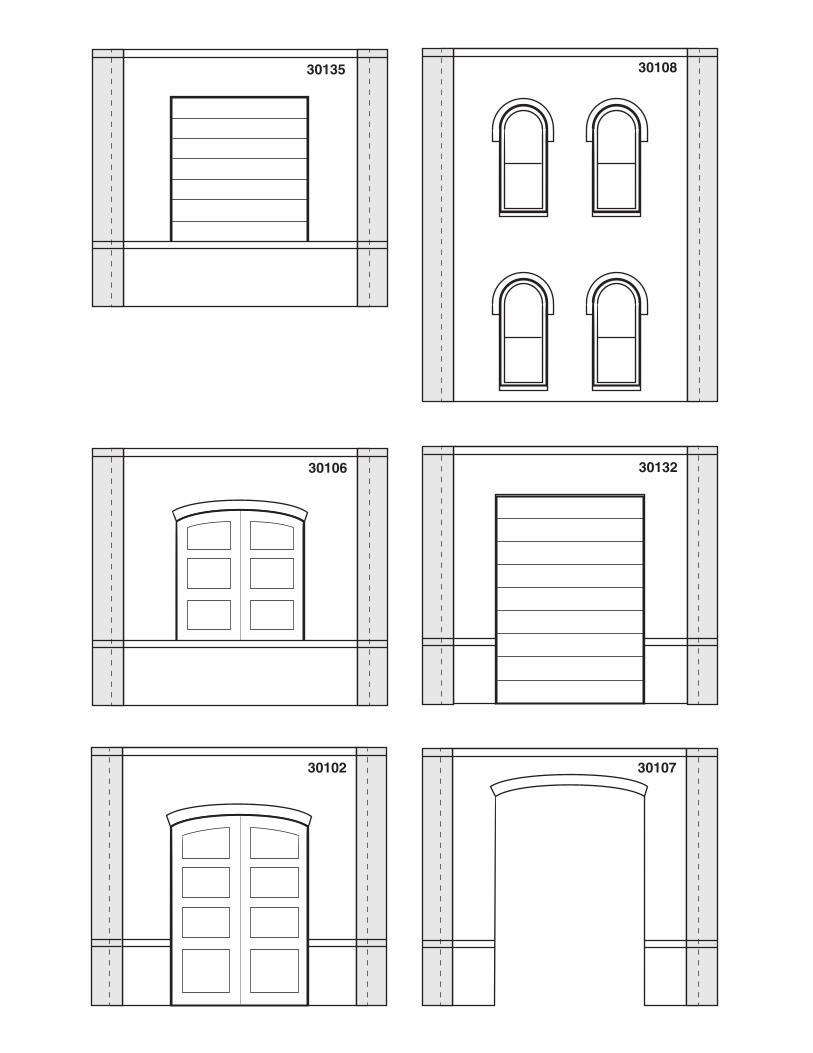
30102Street LevelFreight Door
30132Street LevelOverhead Door
30107Street LevelOpen Arch
30104Street LevelBlank Wall POWERHOUSE
WINDOW2 11/16" w x 7 3/8" h(2 sets per pkg)
30118Powerhouse Window
TWO-STORY WALL SECTIONS2 11/16" w x 3 11/16" h (4 per pkg)
30137Two-StoryRectangular 2 Window (LOW)
30144Two-StoryVictorian Window
30164Two-Story20th Century Window
30174Two-StorySteel Sash Window
30111Two-StoryBlank Wall
CORNICE2 11/16" w x 3/8" h
(8 per pkg)
30114CorniceFancy
30117CornicePlain
ONE-STORY WALL SECTIONS2 11/16" w x 1 7/8" h (4 per pkg)
30112One-StoryArched Window
30130One-StoryRectangular Window
30147One-StoryVictorian Window
30167One-Story20th Century Window
30175One-StorySteel Sash Window
30113One-StoryBlank Wall
DOCK LEVEL WALL SECTIONS2 11/16" w x 2 11/16" h (4 per pkg)
30105Dock LevelArched Entry
30103Dock LevelArched Window
30136Dock LevelRectangular Entry
30133Dock LevelRectangular Window
30143Dock LevelVictorian Window
30163Dock Level20th Century Window
30172Dock LevelSteel Sash Entry
30173Dock LevelSteel Sash Window
30106Dock LevelFreight Door
30135Dock LevelOverhead Door
30115Dock Level Wall(8 per pkg)
30104Street/Dock LevelBlank Wall
CAUTION: Cutting tools recommended.
Use with care.
MODELING AND CARE INFORMATION: This kit suggests the use of materials that may stain or cause damage. Take care to cover project area and clothing appropriately. Follow recommendations for use and cleanup.
Model making product. Not a toy! Not suitable for children under 14 years!
30108Two-StoryArched 4 Window
30109Two-StoryArched 2 Window (HI)
30110Two-StoryArched 2 Window (LOW)
30138Two-StoryRectangular 4 Window
30139Two-StoryRectangular 2 Window (HI)
Model making product. Not a toy! Not suitable for children under 14 years! / Produit pour le modélisme. Pas un jouet! Pas adapté aux enfants de moins de 14 ans! / Producto para modelismo. No es un juguete! No adecuado para niños menores de 14 años! / Modellbauartikel. Kein Spielzeug! Nicht geeigent für Kinder unter 14!
WOODLAND SCENICS®
Manufactured by WOODLAND®
PO BOX 98, LINN CREEK, MO 65052 • woodlandscenics.comDistributed in Europe by Bachmann Europe Plc, Moat Way, Barwell, LE9 8EY, England
®
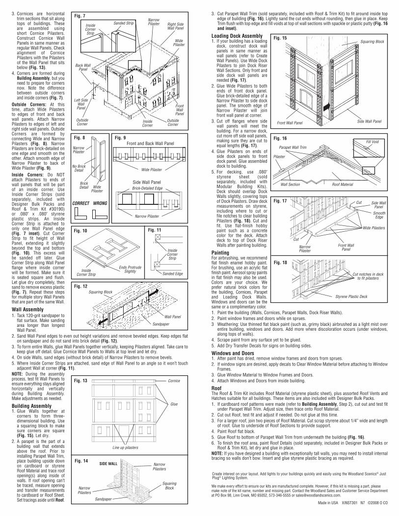
3. Cut Parapet Wall Trim (sold separately, included with Roof & Trim Kit) to fit around inside top edge of building (Fig. 16). Lightly sand the cut ends without rounding, then glue in place. Keep Trim flush with top edge and fill voids at top of wall sections with spackle or plastic putty (Fig. 16 and inset).
Loading Dock Assembly1. If your building has a loading
dock, construct dock wall panels in same manner as wall panels (refer to Create Wall Panels). Use Wide Dock Pilasters to join Dock Riser Wall Sections. Only front and side dock wall panels are needed (Fig. 17).
2. Glue Wide Pilasters to both ends of front dock panel. Glue brick-detailed edge of a Narrow Pilaster to side dock panel. The smooth edge of Narrow Pilaster will join front wall panel at corner.
3. Cut off flanges where side wall panels will meet the building. For a narrow dock, cut more off side wall panels, making sure they are cut to equal lengths (Fig. 17).
4. Glue Pilasters on ends of side dock panels to front dock panel. Glue assembled dock to building.
5. For decking, use .080" styrene sheet (sold separately, included with Modular Building Kits). Deck should overlap Dock Walls slightly, covering tops of Dock Pilasters. Draw deck measurements on styrene, including where to cut or file notches to clear building Pilasters (Fig. 18). Cut and fit. Use flat-finish hobby paint such as a concrete color for the deck. Attach deck to top of Dock Riser Walls after painting building.
PaintingFor airbrushing, we recommend flat finish enamel hobby paint. For brushing, use an acrylic flat finish paint. Aerosol spray paints in flat finish may also be used. Colors are your choice. We prefer natural brick colors for the building, Cornices, Parapet and Loading Dock Walls. Windows and doors can be the same or a complimentary color.1. Paint the building (Walls, Cornices, Parapet Walls, Dock Riser Walls).2. Paint window frames and doors while on sprues.3 Weathering: Use thinned flat black paint (such as, grimy black) airbrushed as a light mist over
entire building, windows and doors. Add more where discoloration occurs (under windows, along tops of walls).
4. Scrape paint from any surface yet to be glued. 5. Add Dry Transfer Decals for signs on building sides.
Windows and Doors1. After paint has dried, remove window frames and doors from sprues. 2. If window signs are desired, apply decals to Clear Window Material before attaching to Window
Frames. 3. Glue Window Material to Window Frames and Doors. 4. Attach Windows and Doors from inside building.
Roof The Roof & Trim Kit includes Roof Material (styrene plastic sheet), plus assorted Roof Vents and Hatches suitable for all buildings. These items are also included with Designer Bulk Packs.1. If cardboard roof patterns were made (refer to Building Assembly, Step 2), cut out and test fit
under Parapet Wall Trim. Adjust size, then trace onto Roof Material.2. Cut out Roof, test fit and adjust if needed. Do not glue at this time.3. For a larger roof, join two pieces of Roof Material. Cut scrap styrene about 1/4” wide and length
of roof. Glue to underside of Roof Sections to provide support.4. Paint Roof flat black.5. Glue Roof to bottom of Parapet Wall Trim from underneath the building (Fig. 16).6. To finish the roof area, paint Roof Details (sold separately, included in Designer Bulk Packs or
Roof & Trim Kit), let dry and glue in place. NOTE: If you have designed a building with exceptionally tall walls, you may need to install internal bracing so walls don’t bow. Insert and glue styrene plastic bracing as required.
3. Cornices are horizontal trim sections that sit along tops of buildings. These are assembled using short Cornice Pilasters. Construct Cornice Wall Panels in same manner as regular Wall Panels. Check alignment of Cornice Pilasters with the Pilasters of the Wall Panel that sits below (Fig. 13).
4. Corners are formed during Building Assembly, but you need to prepare for corners now. Note the difference between outside corners and inside corners (Fig. 7).
Outside Corners: At this time, attach Wide Pilasters to edges of front and back wall panels. Attach Narrow Pilasters to edges of left and right side wall panels. Outside Corners are formed by connecting Wide and Narrow Pilasters (Fig. 8). Narrow Pilasters are brick-detailed on one edge and smooth on the other. Attach smooth edge of Narrow Pilaster to back of Wide Pilaster (Fig. 9). Inside Corners: Do NOT attach Pilasters to ends of wall panels that will be part of an inside corner. Use Inside Corner Strips (sold separately, included with Designer Bulk Packs and Roof & Trim Kit #30190) or .080" x .080" styrene plastic strips. An Inside Corner Strip is attached to only one Wall Panel edge (Fig. 7 inset). Cut Corner Strip to fit height of Wall Panel, extending it slightly beyond the top and bottom (Fig. 10). This excess will be sanded off later. Glue Corner Strip along Wall Panel flange where inside corner will be formed. Make sure it is seated square and flush. Let glue dry completely, then sand to remove excess plastic (Fig. 7). Repeat these steps for multiple story Wall Panels that are part of the same Wall.
Wall Assembly1. Tack 120-grit sandpaper to
flat surface. Make sanding area longer than longest Wall Panel.
2. Sand Wall Panel edges to even out height variations and remove beveled edges. Keep edges flat on sandpaper and do not sand into brick detail (Fig. 12).
3. To form entire Walls, glue Wall Panels together vertically, keeping Pilasters aligned. Take care to keep glue off detail. Glue Cornice Wall Panels to Walls at top level and let dry.
4. On side Walls, sand edges (without brick detail) of Narrow Pilasters to remove bevels.5. Where Inside Corner Strips are attached, sand edge of Wall Panel to an angle so it won’t touch
adjacent Wall at corner (Fig. 11).NOTE: During the assembly process, test fit Wall Panels to ensure everything stays aligned horizontally and vertically during Building Assembly. Make adjustments as needed.
Building Assembly1. Glue Walls together at
corners to form three-dimensional building. Use a squaring block to make sure corners are square (Fig. 15). Let dry.
2. A parapet is the part of a building wall that extends above the roof. Prior to installing Parapet Wall Trim, place building upside down on cardboard or styrene Roof Material and trace roof opening(s) along inside of walls. If roof opening can’t be traced, measure opening and transfer measurements to cardboard or Roof Sheet. Set tracings aside until Roof.
Side Wall Panel
Front and Back Wall Panel
Wide Pilaster
Narrow Pilaster
Brick-Detailed Edge
Fig. 9
Fig. 7
Sanded StripInside Corner Strip
Back Wall Panel
Outside Corner
Inside Corner
Left Side Wall Panel Front
Wall Panel
Narrow Pilaster Right Side
Wall Panel
Wide Pilaster
Outside Corner
Fig. 8
CORRECT
Narrow Pilaster
WRONG
Wide Pilaster
No Brick Detail
Fig. 12
Wall Panel
Sandpaper
Squaring Block
Fig. 16
Roof MaterialWall Section
Pilaster
Parapet Wall TrimFill Void
Squaring Block
Side Wall PanelFront Wall Panel
Fig. 17
Fig. 18
Cut notches in deck to fit pilasters
Styrene Plastic Deck
Front Wall Panel
Smooth Edge
Side Wall Panel
Wide Pilasters
Narrow Pilaster
Cut
Cut
Fig. 10 Fig. 11
Inside Corner Strip
Ends Protrude Slightly
Sanded Edge
Inside Corner Strip
Made in USA XINST301 N7 ©2008 O CO
We make every effort to ensure our kits are manufactured complete. However, if this kit is missing a part, please make note of the kit name, number and missing part. Contact the Woodland Sales and Customer Service Department at PO Box 98, Linn Creek, MO 65052, 573-346-5555 or [email protected].
Brick Detail
Fig. 13 Cornice
Glue
Line up pilasters
Fig. 14Narrow Pilasters
Narrow Pilasters
Squaring Block
SIDE WALL
Sandpaper
Fig. 15
Create interest on your layout. Add lights to your buildings quickly and easily using the Woodland Scenics® Just Plug® Lighting System.
DPM ®LANDMARK STRUCTURES ®
HO SCALE MODULAR WALL SYSTEMPLANNING PACKET 30191
WOODLAND SCENICS® Manufactured by WOODLAND® • PO BOX 98, LINN CREEK, MO 65052 • N7 • woodlandscenics.com
30143
30141
30144
30142
30114
CORNICE
XINST30191A N7 ©2008 O CO
30147
Glue Tab
Pilaster (glue tab) P
ilast
er (
glue
tab)
#30191A
HO SCALEPLANNING SHEET
®
Kit Contents: 2 Planning Sheets, Instructions
Combination PackageMade in USA N7
N0707
MODULAR WALL SYSTEM PLANNING PACKET
Pilaster (glue tab)
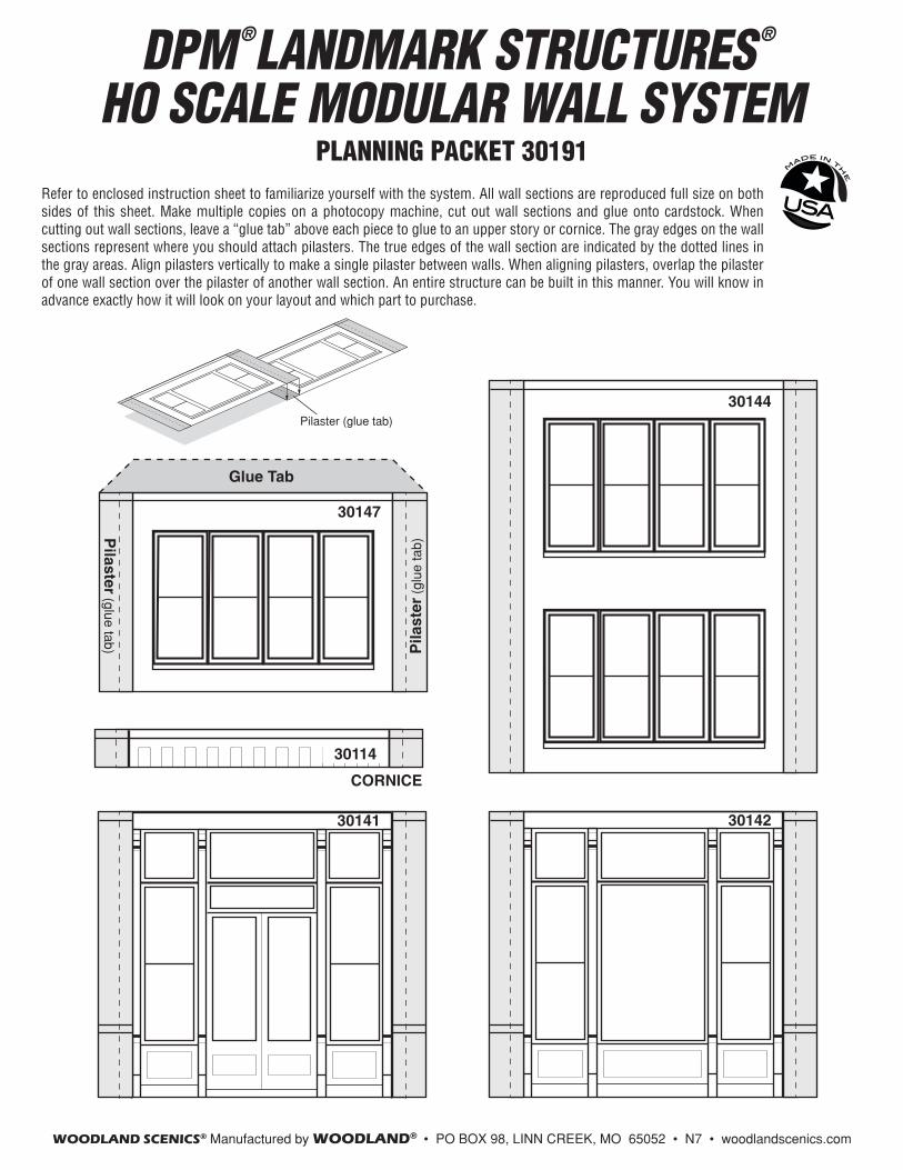
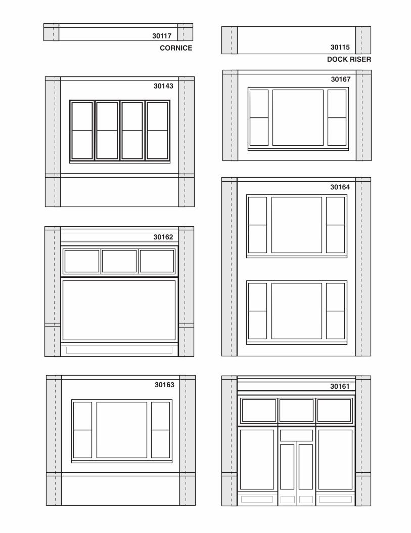
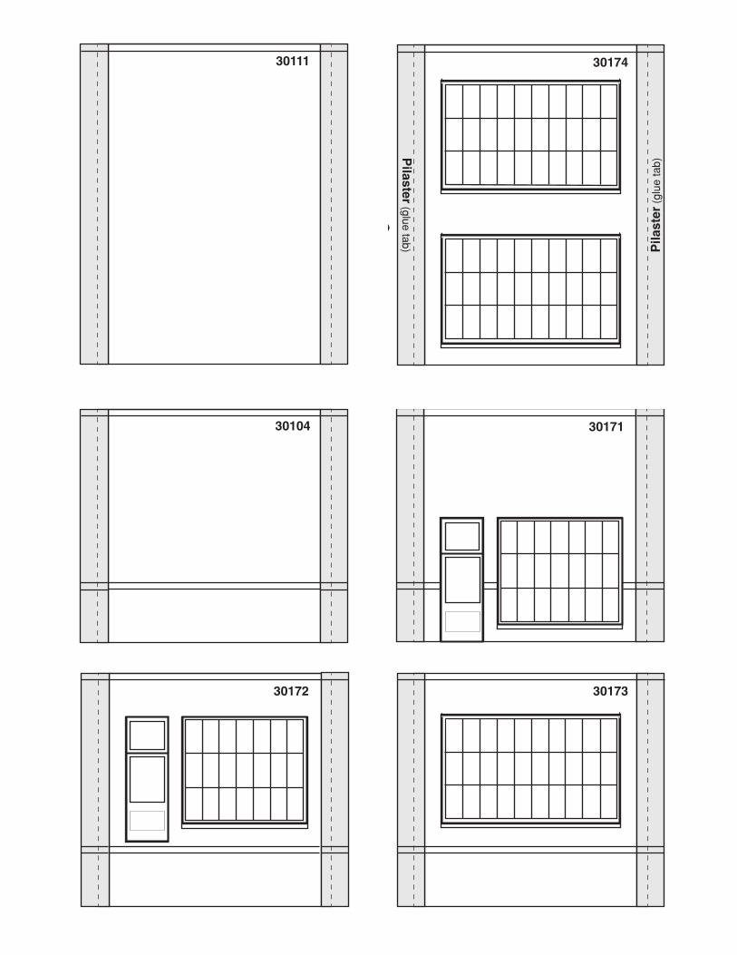
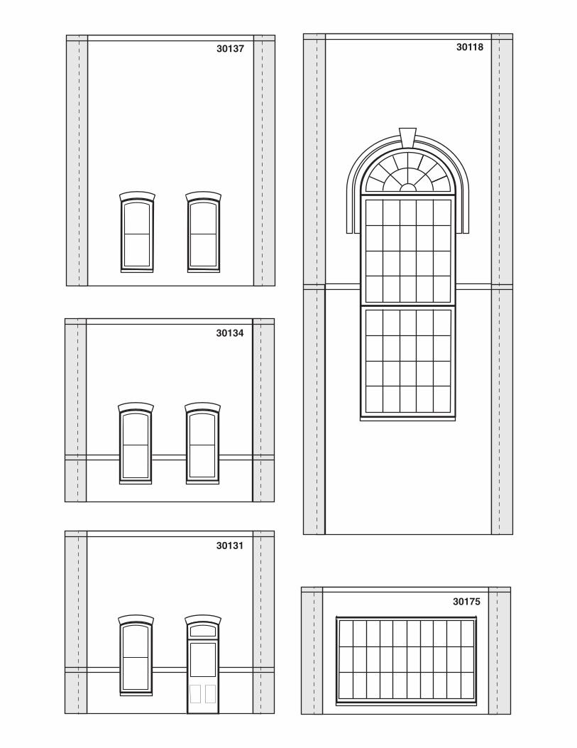
Refer to enclosed instruction sheet to familiarize yourself with the system. All wall sections are reproduced full size on both sides of this sheet. Make multiple copies on a photocopy machine, cut out wall sections and glue onto cardstock. When cutting out wall sections, leave a “glue tab” above each piece to glue to an upper story or cornice. The gray edges on the wall sections represent where you should attach pilasters. The true edges of the wall section are indicated by the dotted lines in the gray areas. Align pilasters vertically to make a single pilaster between walls. When aligning pilasters, overlap the pilaster of one wall section over the pilaster of another wall section. An entire structure can be built in this manner. You will know in advance exactly how it will look on your layout and which part to purchase.
30143
30141
30144
30142
30114
CORNICE
XINST30191A N7 ©2008 O CO
30147
Glue Tab
Pilaster (glue tab) P
ilast
er (
glue
tab)
#30191A
HO SCALEPLANNING SHEET
®
Kit Contents: 2 Planning Sheets, Instructions
Combination PackageMade in USA N7
N0707
MODULAR WALL SYSTEM PLANNING PACKET
Pilaster (glue tab)
Refer to enclosed instruction sheet to familiarize yourself with the system. All wall sections are reproduced full size on both sides of this sheet. Make multiple copies on a photocopy machine, cut out wall sections and glue onto cardstock. When cutting out wall sections, leave a “glue tab” above each piece to glue to an upper story or cornice. The gray edges on the wall sections represent where you should attach pilasters. The true edges of the wall section are indicated by the dotted lines in the gray areas. Align pilasters vertically to make a single pilaster between walls. When aligning pilasters, overlap the pilaster of one wall section over the pilaster of another wall section. An entire structure can be built in this manner. You will know in advance exactly how it will look on your layout and which part to purchase.
Refer to enclosed instruction sheet to familiarize yourself with the system. All wall sections are reproduced full size on both sides of this sheet. Make multiple copies on a photocopy machine, cut out wall sections and glue onto cardstock. When cutting out wall sections, leave a “glue tab” above each piece to glue to an upper story or cornice. The gray edges on the wall sections represent where you should attach pilasters. The true edges of the wall section are indicated by the dotted lines in the gray areas. Align pilasters vertically to make a single pilaster between walls. When aligning pilasters, overlap the pilaster of one wall section over the pilaster of another wall section. An entire structure can be built in this manner. You will know in advance exactly how it will look on your layout and which part to purchase.
Pilaster (glue tab)
30164
30115
301613016330162
30167
DOCK RISER
30117
CORNICE
30164
30115
301613016330162
30167
DOCK RISER
30117
CORNICE
30164
30115
301613016330162
30167
DOCK RISER
30117
CORNICE
30143
30141
30144
30142
30114
CORNICE
XINST30191A N7 ©2008 O CO
30147
Glue Tab
Pilaster (glue tab) P
ilast
er (
glue
tab)
#30191A
HO SCALEPLANNING SHEET
®
Kit Contents: 2 Planning Sheets, Instructions
Combination PackageMade in USA N7
N0707
MODULAR WALL SYSTEM PLANNING PACKET
Pilaster (glue tab)
Refer to enclosed instruction sheet to familiarize yourself with the system. All wall sections are reproduced full size on both sides of this sheet. Make multiple copies on a photocopy machine, cut out wall sections and glue onto cardstock. When cutting out wall sections, leave a “glue tab” above each piece to glue to an upper story or cornice. The gray edges on the wall sections represent where you should attach pilasters. The true edges of the wall section are indicated by the dotted lines in the gray areas. Align pilasters vertically to make a single pilaster between walls. When aligning pilasters, overlap the pilaster of one wall section over the pilaster of another wall section. An entire structure can be built in this manner. You will know in advance exactly how it will look on your layout and which part to purchase.
30164
30115
301613016330162
30167
DOCK RISER
30117
CORNICE
30164
30115
301613016330162
30167
DOCK RISER
30117
CORNICE
30164
30115
301613016330162
30167
DOCK RISER
30117
CORNICE
30164
30115
301613016330162
30167
DOCK RISER
30117
CORNICE
30174
30173
3013230135
30130
30175
30137
30172
30171
30139
30133
30134
30138
30136
30131
XIN
ST30
191B
N7
©20
08 O
CO
Pilaster (glue tab) P
ilast
er (
glue
tab)
#301
91B
HO
SC
AL
EP
LA
NN
ING
SH
EE
T ®
MO
DU
LA
R W
AL
L S
YS
TE
M
PL
AN
NIN
G P
AC
KE
T
Pila
ster
(gl
ue ta
b)
Refe
r to
encl
osed
inst
ruct
ion
shee
t to
fam
iliariz
e yo
urse
lf w
ith th
e sy
stem
. All
wal
l se
ctio
ns a
re re
prod
uced
full s
ize o
n bo
th s
ides
of t
his
shee
t. M
ake
mul
tiple
cop
ies
on
a ph
otoc
opy
mac
hine
, cut
out
wal
l sec
tions
and
glu
e on
to c
ards
tock
. Whe
n cu
tting
ou
t wal
l sec
tions
, lea
ve a
“gl
ue ta
b” a
bove
eac
h pi
ece
to g
lue
to a
n up
per s
tory
or
corn
ice.
The
gra
y ed
ges
on th
e w
all s
ectio
ns r
epre
sent
whe
re y
ou s
houl
d at
tach
pi
last
ers.
The
true
edg
es o
f the
wal
l sec
tion
are
indi
cate
d by
the
dotte
d lin
es in
the
gray
are
as. A
lign
pila
ster
s ve
rtica
lly to
mak
e a
sing
le p
ilast
er b
etw
een
wal
ls. W
hen
alig
ning
pila
ster
s, o
verla
p th
e pi
last
er o
f one
wal
l sec
tion
over
the
pila
ster
of a
noth
er
wal
l sec
tion.
An
entir
e st
ruct
ure
can
be b
uilt
in th
is
man
ner.
You
will
kno
w in
adv
ance
exa
ctly
ho
w it
will
look
on
your
layo
ut a
nd
whi
ch p
art t
o pu
rcha
se.
30108
30103
30106
30109
30101
30102
30110
30105
30107
30111
30104
30113
30118
30112
30108
30103
30106
30109
30101
30102
30110
30105
30107
30111
30104
30113
30118
30112

30174
30173
3013230135
30130
30175
30137
30172
30171
30139
30133
30134
30138
30136
30131
XIN
ST30
191B
N7
©20
08 O
CO
Pilaster (glue tab) P
ilast
er (
glue
tab)
#301
91B
HO
SC
AL
EP
LA
NN
ING
SH
EE
T ®
MO
DU
LA
R W
AL
L S
YS
TE
M
PL
AN
NIN
G P
AC
KE
T
Pila
ster
(gl
ue ta
b)
Refe
r to
encl
osed
inst
ruct
ion
shee
t to
fam
iliariz
e yo
urse
lf w
ith th
e sy
stem
. All
wal
l se
ctio
ns a
re re
prod
uced
full s
ize o
n bo
th s
ides
of t
his
shee
t. M
ake
mul
tiple
cop
ies
on
a ph
otoc
opy
mac
hine
, cut
out
wal
l sec
tions
and
glu
e on
to c
ards
tock
. Whe
n cu
tting
ou
t wal
l sec
tions
, lea
ve a
“gl
ue ta
b” a
bove
eac
h pi
ece
to g
lue
to a
n up
per s
tory
or
corn
ice.
The
gra
y ed
ges
on th
e w
all s
ectio
ns r
epre
sent
whe
re y
ou s
houl
d at
tach
pi
last
ers.
The
true
edg
es o
f the
wal
l sec
tion
are
indi
cate
d by
the
dotte
d lin
es in
the
gray
are
as. A
lign
pila
ster
s ve
rtica
lly to
mak
e a
sing
le p
ilast
er b
etw
een
wal
ls. W
hen
alig
ning
pila
ster
s, o
verla
p th
e pi
last
er o
f one
wal
l sec
tion
over
the
pila
ster
of a
noth
er
wal
l sec
tion.
An
entir
e st
ruct
ure
can
be b
uilt
in th
is
man
ner.
You
will
kno
w in
adv
ance
exa
ctly
ho
w it
will
look
on
your
layo
ut a
nd
whi
ch p
art t
o pu
rcha
se.
30108
30103
30106
30109
30101
30102
30110
30105
30107
30111
30104
30113
30118
30112
30108
30103
30106
30109
30101
30102
30110
30105
30107
30111
30104
30113
30118
30112
30174
30173
3013230135
30130
30175
30137
30172
30171
30139
30133
30134
30138
30136
30131
XIN
ST30
191B
N7
©20
08 O
CO
Pilaster (glue tab) P
ilast
er (
glue
tab)
#301
91B
HO
SC
AL
EP
LA
NN
ING
SH
EE
T ®
MO
DU
LA
R W
AL
L S
YS
TE
M
PL
AN
NIN
G P
AC
KE
T
Pila
ster
(gl
ue ta
b)
Refe
r to
encl
osed
inst
ruct
ion
shee
t to
fam
iliariz
e yo
urse
lf w
ith th
e sy
stem
. All
wal
l se
ctio
ns a
re re
prod
uced
full s
ize o
n bo
th s
ides
of t
his
shee
t. M
ake
mul
tiple
cop
ies
on
a ph
otoc
opy
mac
hine
, cut
out
wal
l sec
tions
and
glu
e on
to c
ards
tock
. Whe
n cu
tting
ou
t wal
l sec
tions
, lea
ve a
“gl
ue ta
b” a
bove
eac
h pi
ece
to g
lue
to a
n up
per s
tory
or
corn
ice.
The
gra
y ed
ges
on th
e w
all s
ectio
ns r
epre
sent
whe
re y
ou s
houl
d at
tach
pi
last
ers.
The
true
edg
es o
f the
wal
l sec
tion
are
indi
cate
d by
the
dotte
d lin
es in
the
gray
are
as. A
lign
pila
ster
s ve
rtica
lly to
mak
e a
sing
le p
ilast
er b
etw
een
wal
ls. W
hen
alig
ning
pila
ster
s, o
verla
p th
e pi
last
er o
f one
wal
l sec
tion
over
the
pila
ster
of a
noth
er
wal
l sec
tion.
An
entir
e st
ruct
ure
can
be b
uilt
in th
is
man
ner.
You
will
kno
w in
adv
ance
exa
ctly
ho
w it
will
look
on
your
layo
ut a
nd
whi
ch p
art t
o pu
rcha
se.
30108
30103
30106
30109
30101
30102
30110
30105
30107
30111
30104
30113
30118
30112
30108
30103
30106
30109
30101
30102
30110
30105
30107
30111
30104
30113
30118
30112
30108
30103
30106
30109
30101
30102
30110
30105
30107
30111
30104
30113
30118
30112
30108
30103
30106
30109
30101
30102
30110
30105
30107
30111
30104
30113
30118
30112
30108
30103
30106
30109
30101
30102
30110
30105
30107
30111
30104
30113
30118
30112
30108
30103
30106
30109
30101
30102
30110
30105
30107
30111
30104
30113
30118
30112
30108
30103
30106
30109
30101
30102
30110
30105
30107
30111
30104
30113
30118
30112