Embed Size (px)
Citation preview
DOCSIS® Provisioning of EPON Specifications DPoEv2.0
DPoE Metro Ethernet Forum Specification
DPoE-SP-MEFv2.0-I05-170111 ISSUED
Notice
This DPoE™ specification is the result of a cooperative effort undertaken at the direction of Cable Television Laboratories, Inc. for the benefit of the cable industry and its customers. You may download, copy, distribute, and reference the documents herein only for the purpose of developing products or services in accordance with such documents, and educational use. Except as granted by CableLabs® in a separate written license agreement, no license is granted to modify the documents herein (except via the Engineering Change process), or to use, copy, modify or distribute the documents for any other purpose.
This document may contain references to other documents not owned or controlled by CableLabs. Use and understanding of this document may require access to such other documents. Designing, manufacturing, distributing, using, selling, or servicing products, or providing services, based on this document may require intellectual property licenses from third parties for technology referenced in this document. To the extent this document contains or refers to documents of third parties, you agree to abide by the terms of any licenses associated with such third party documents, including open source licenses, if any.
Cable Television Laboratories, Inc., 2012-2017
DPoE-SP-MEFv2.0-I05-170111 DOCSIS® Provisioning of EPON Specifications
2 CableLabs 01/11/17
DISCLAIMER
This document is furnished on an "AS IS" basis and neither CableLabs nor its members provides any representation or warranty, express or implied, regarding the accuracy, completeness, noninfringement, or fitness for a particular purpose of this document, or any document referenced herein. Any use or reliance on the information or opinion in this document is at the risk of the user, and CableLabs and its members shall not be liable for any damage or injury incurred by any person arising out of the completeness, accuracy, or utility of any information or opinion contained in the document.
CableLabs reserves the right to revise this document for any reason including, but not limited to, changes in laws, regulations, or standards promulgated by various entities, technology advances, or changes in equipment design, manufacturing techniques, or operating procedures described, or referred to, herein.
This document is not to be construed to suggest that any company modify or change any of its products or procedures, nor does this document represent a commitment by CableLabs or any of its members to purchase any product whether or not it meets the characteristics described in the document. Unless granted in a separate written agreement from CableLabs, nothing contained herein shall be construed to confer any license or right to any intellectual property. This document is not to be construed as an endorsement of any product or company or as the adoption or promulgation of any guidelines, standards, or recommendations.
DPoE Metro Ethernet Forum Specification DPoE-SP-MEFv2.0-I05-170111
01/11/17 CableLabs 3
Document Status Sheet
Document Control Number: DPoE-SP-MEFv2.0-I05-170111
Document Title: DPoE Metro Ethernet Forum Specification
Revision History: I01 - Released 10/04/2012 I02 - Released 08/08/2013 I03 - Released 08/07/2014 I04 - Released 06/02/2016 I05 – Released 01/11/2017
Date: January 11, 2017
Status: Work in Progress
Draft Issued Closed
Distribution Restrictions: Author Only
CL/Member CL/ Member/ Vendor
Public
Key to Document Status Codes
Work in Progress An incomplete document, designed to guide discussion and generate feedback that may include several alternative requirements for consideration.
Draft A document in specification format considered largely complete, but lacking review by Members and vendors. Drafts are susceptible to substantial change during the review process.
Issued A generally public document that has undergone Member and Technology Supplier review, cross-vendor interoperability, and is for Certification testing if applicable. Issued Specifications are subject to the Engineering Change Process.
Closed A static document, reviewed, tested, validated, and closed to further engineering change requests to the specification through CableLabs.
Trademarks CableLabs® is a registered trademark of Cable Television Laboratories, Inc. Other CableLabs marks are listed at http://www.cablelabs.com/certqual/trademarks. All other marks are the property of their respective owners.
DPoE-SP-MEFv2.0-I05-170111 DOCSIS® Provisioning of EPON Specifications
4 CableLabs 01/11/17
Contents 1 INTRODUCTION ............................................................................................................................................... 9
1.1 DPoE Technology Introduction ..................................................................................................................... 9 1.2 Scope ........................................................................................................................................................... 10 1.3 Goals ............................................................................................................................................................ 10 1.4 Requirements ............................................................................................................................................... 10 1.5 DPoE Version 2.0 Specifications ................................................................................................................. 11 1.6 Reference Architecture ................................................................................................................................ 12 1.7 DPoE Interfaces and Reference Points ........................................................................................................ 13
2 REFERENCES .................................................................................................................................................. 16 2.1 Normative References.................................................................................................................................. 16 2.2 Informative References ................................................................................................................................ 17 2.3 Reference Acquisition.................................................................................................................................. 18
3 TERMS AND DEFINITIONS .......................................................................................................................... 19 3.1 DPoE Network Elements ............................................................................................................................. 19 3.2 Other Terms ................................................................................................................................................. 21
4 ABBREVIATIONS AND ACRONYMS ......................................................................................................... 22
5 OVERVIEW AND THEORY OF OPERATION ........................................................................................... 26 5.1 MEF Key Features ....................................................................................................................................... 26
Metro Ethernet E-Line Service ............................................................................................................ 26 5.1.1 Metro Ethernet E-LAN Service ............................................................................................................ 26 5.1.2 Metro Ethernet E-Tree Service ............................................................................................................ 26 5.1.3
5.2 Technical Overview ..................................................................................................................................... 27 5.3 MEF Operation Overview ........................................................................................................................... 27
Overview of the Operations in the Upstream Direction ...................................................................... 28 5.3.1 Overview of the Operation in the Downstream Direction ................................................................... 29 5.3.2
5.4 Relationship to the DOCSIS L2VPN ........................................................................................................... 30
6 METRO ETHERNET SERVICE REQUIREMENTS (NORMATIVE) ...................................................... 31 6.1 Interface Types and Requirements ............................................................................................................... 31
Interface Types and Requirements (D-ONU) ....................................................................................... 31 6.1.1 Interface Types and Requirements (DPoE System) ............................................................................. 31 6.1.2
6.2 Encapsulation Mode .................................................................................................................................... 32 Upstream direction .............................................................................................................................. 32 6.2.1 Downstream direction.......................................................................................................................... 32 6.2.2
6.3 Transport Mode ........................................................................................................................................... 33 Upstream direction .............................................................................................................................. 33 6.3.1 Downstream direction.......................................................................................................................... 33 6.3.2
6.4 Provider Bridging (PB) and Provider Backbone Bridging (PBB) ............................................................... 33 PB Requirements ................................................................................................................................. 33 6.4.1 PBB Requirements ............................................................................................................................... 35 6.4.2
6.5 Frame Formats ............................................................................................................................................. 37 6.6 L2CP Processing .......................................................................................................................................... 38 6.7 Tag Protocol Identifier (TPID) Translation ................................................................................................. 40 6.8 CoS Mapping ............................................................................................................................................... 41 6.9 QoS for Metro Ethernet Services ................................................................................................................. 41
Metro Ethernet Service Profile (MESP) .............................................................................................. 42 6.9.1 DOCSIS QoS Parameters (DQP) ........................................................................................................ 44 6.9.2 Upstream QoS Enforcement Requirements .......................................................................................... 45 6.9.3 Downstream QoS Enforcement Requirements ..................................................................................... 46 6.9.4
DPoE Metro Ethernet Forum Specification DPoE-SP-MEFv2.0-I05-170111
01/11/17 CableLabs 5
6.10 Ethernet Service OAM (S-OAM) ................................................................................................................ 47 6.11 Configuration and Management .................................................................................................................. 47
Transport and Encapsulation Mode Configuration Requirements ...................................................... 47 6.11.1 [802.1ad] Tagging Configuration Requirements ................................................................................. 48 6.11.2 [802.1ah] Encapsulation Configuration Requirements ....................................................................... 48 6.11.3 TPID Translation Configuration Requirements................................................................................... 50 6.11.4 L2CP Configuration Requirements ...................................................................................................... 50 6.11.5 MEF QoS Configuration Requirements ............................................................................................... 51 6.11.6
6.12 Metro Ethernet Service Attributes ............................................................................................................... 51 6.13 DOCSIS L2VPN TLVs ............................................................................................................................... 52
7 MEF USAGE ACCOUNTING REQUIREMENTS (NORMATIVE)........................................................... 53
ANNEX A PARAMETER ENCODINGS (NORMATIVE) .............................................................................. 54 A.1 L2VPN Mode .............................................................................................................................................. 54 A.2 [802.1ad] Encapsulation .............................................................................................................................. 54 A.3 [802.1ah] Encapsulation .............................................................................................................................. 54
A.3.1 [802.1ah] I-TCI ................................................................................................................................... 54 A.3.2 MAC Address of the Destination Backbone Edge Bridge (B-DA) ....................................................... 54 A.3.3 [802.1ah] B-TCI .................................................................................................................................. 55 A.3.4 [802.1ah] I-TPID ................................................................................................................................. 55 A.3.5 [802.1ah] I-PCP .................................................................................................................................. 55 A.3.6 [802.1ah] I-DEI ................................................................................................................................... 55 A.3.7 [802.1ah] I-UCA .................................................................................................................................. 56 A.3.8 [802.1ah] I-SID ................................................................................................................................... 56 A.3.9 [802.1ah] B-TPID ................................................................................................................................ 56 A.3.10 [802.1ah] B-PCP ................................................................................................................................. 56 A.3.11 [802.1ah] B-DEI .................................................................................................................................. 56 A.3.12 [802.1ah] B-VID .................................................................................................................................. 57
A.4 TPID Translation ......................................................................................................................................... 57 A.4.1 Upstream TPID Translation ................................................................................................................ 57 A.4.2 Downstream TPID Translation............................................................................................................ 57 A.4.3 Upstream S-TPID Translation ............................................................................................................. 58 A.4.4 Downstream S-TPID Translation ........................................................................................................ 58 A.4.5 Upstream B-TPID Translation ............................................................................................................ 58 A.4.6 Downstream B-TPID Translation ........................................................................................................ 58 A.4.7 Upstream I-TPID Translation.............................................................................................................. 58 A.4.8 Downstream I-TPID Translation ......................................................................................................... 59
A.5 L2CP Processing .......................................................................................................................................... 59 A.5.1 CMIM Filter......................................................................................................................................... 59 A.5.2 L2CP Mode .......................................................................................................................................... 59 A.5.3 L2CP L2PT D-MAC Address ............................................................................................................... 60 A.5.4 L2CP Filter .......................................................................................................................................... 60
A.6 Pseudowire Class ......................................................................................................................................... 61 A.7 Service Delimiter ......................................................................................................................................... 61 A.8 Virtual Switch Instance Encoding ............................................................................................................... 62
A.8.1 VPLS Class .......................................................................................................................................... 62 A.8.2 E-Tree Role .......................................................................................................................................... 62 A.8.3 E-Tree Root VID .................................................................................................................................. 63 A.8.4 E-Tree Leaf VID .................................................................................................................................. 63 A.8.5 BGP Attribute sub TLV ........................................................................................................................ 64 A.8.6 VPN-SG Attribute sub TLV .................................................................................................................. 65 A.8.7 Network Timing Profile Reference ....................................................................................................... 65
ANNEX B METRO ETHERNET SERVICE ATTRIBUTES (NORMATIVE) ............................................. 66 B.1 MEF EPL Service Attributes (Informative) ................................................................................................. 66
DPoE-SP-MEFv2.0-I05-170111 DOCSIS® Provisioning of EPON Specifications
6 CableLabs 01/11/17
B.2 EVPL Service .............................................................................................................................................. 69 B.3 EP-LAN service ........................................................................................................................................... 71 B.4 EVP-LAN Service ....................................................................................................................................... 74 B.5 EP-Tree Service ........................................................................................................................................... 77 B.6 EVP-Tree Service ........................................................................................................................................ 79
APPENDIX I ACKNOWLEDGMENTS (INFORMATIVE) ............................................................................ 83
APPENDIX II REVISION HISTORY .............................................................................................................. 84 II.1 Engineering Change for DPoE-SP-MEFv2.0-I02-130808 .......................................................................... 84 II.2 Engineering Change for DPoE-SP-MEFv2.0-I03-140807 .......................................................................... 84 II.3 Engineering Change for DPoE-SP-MEFv2.0-I04-160602 .......................................................................... 84 II.4 Engineering Change for DPoE-SP-MEFv2.0-I05-170111 .......................................................................... 84
DPoE Metro Ethernet Forum Specification DPoE-SP-MEFv2.0-I05-170111
01/11/17 CableLabs 7
Figures Figure 1 - DPoEv2.0 Reference Architecture .............................................................................................................. 12 Figure 2 - DPoEv2.0 Interfaces and Reference Points ................................................................................................. 13 Figure 3 - D-ONU Types ............................................................................................................................................. 20 Figure 4 - DPoE Network Elements ............................................................................................................................ 20
Tables Table 1 - DPoEv2.0 Specifications .............................................................................................................................. 11 Table 2 - DPoEv2.0 Interface and Reference Point Descriptions ................................................................................ 14 Table 3 - Acceptable Frame Formats for DPoE Interfaces (PB Transport and Encapsulation Mode) ......................... 38 Table 4 - Acceptable Frame Formats for DPoE Interfaces (PBB Transport and Encapsulation Mode) ...................... 38 Table 5 - Layer 2 Control Protocol Mac Addresses .................................................................................................... 38 Table 6 - Layer 2 Control Protocol Identifiers............................................................................................................. 39 Table 7 - L2PT Protocol Mac Addresses ..................................................................................................................... 40 Table 8 - Definition of MEF Bandwidth Profile .......................................................................................................... 43 Table 9 – L2CP Identifiers .......................................................................................................................................... 59 Table 10 - MEF UNI (MU) Service Attributes for EPL Service ................................................................................. 66 Table 11 - EVC per UNI Service Attributes for EPL Service ..................................................................................... 67 Table 12 - EVC Service Attributes for EPL Service ................................................................................................... 68 Table 13 - MEF UNI (MU) Service Attributes for EVPL Service .............................................................................. 69 Table 14 - EVC per UNI Service Attributes for EVPL Service .................................................................................. 70 Table 15 - EVC Service Attributes for EVPL Service................................................................................................. 71 Table 16 - MEF UNI (MU) Service Attributes for EP-LAN Service .......................................................................... 72 Table 17 - EVC per UNI Service Attributes for EP-LAN Service .............................................................................. 73 Table 18 - EVC Service Attributes for EP-LAN Service ............................................................................................ 73 Table 19 - MEF UNI (MU) Service Attributes for EVP-LAN Service ....................................................................... 74 Table 20 - EVC per UNI Service Attributes for EVP-LAN Service ........................................................................... 75 Table 21 - EVC Service Attributes for EVP-LAN Service ......................................................................................... 76 Table 22 - MEF UNI (MU) Service Attributes for EP-Tree Service ........................................................................... 77 Table 23 - EVC per UNI Service Attributes for EP-Tree Service ............................................................................... 78 Table 24 - EVC Service Attributes for EP-Tree Service ............................................................................................. 79 Table 25 - MEF UNI (MU) Service Attributes for EVP-Tree Service ........................................................................ 80 Table 26 - EVC per UNI Service Attributes for EVP-Tree Service ............................................................................ 81 Table 27 - EVC Service Attributes for EVP-Tree Service .......................................................................................... 81

DPoE-SP-MEFv2.0-I05-170111 DOCSIS® Provisioning of EPON Specifications
8 CableLabs 01/11/17
This page intentionally left blank.

DPoE Metro Ethernet Forum Specification DPoE-SP-MEFv2.0-I05-170111
01/11/17 CableLabs 9
1 INTRODUCTION DOCSIS Provisioning of EPON (DPoE) version 2.0 specifications are a joint effort of Cable Television Laboratories (CableLabs), cable operators, vendors, and suppliers to support EPON technology using existing DOCSIS-based back office systems and processes. DPoEv2.0 specifications augment the DPoEv1.0 specifications to provide requirements for additional service capabilities and corresponding provisioning and network management capabilities.
Ethernet PON (EPON) is an [802.3] standard for a passive optical network (PON). A PON is a specific type of multi-access optical network. A multi-access optical network is an optical fiber-based network technology that permits more than two network elements to transmit and receive on the same fiber.
DPoE specifications are focused on DOCSIS-based provisioning and operations of Internet Protocol (IP) using DOCSIS Internet service (which is typically referred to as High Speed Data (HSD)), or IP(HSD) for short, and Metro Ethernet services as described by Metro Ethernet Forum (MEF) standards. DPoE Networks offer IP(HSD) services, functionally equivalent to DOCSIS networks, where the DPoE System acts like a DOCSIS CMTS and the DPoE System and DPoE Optical Network Unit (ONU) together act like a DOCSIS CM.
1.1 DPoE Technology Introduction1
DPoE technology was established with the following common requirements already developed by operators. Each of the participant operators had previously selected 1G-EPON and 10G-EPON as the appropriate technology for one or more applications. EPON is a widely deployed technology with a sufficient and large supply of vendors offering a variety of products for each component of the access network. 2G-EPON, as described in Annex A of [DPoE-PHYv2.0], uses the same 1G upstream as 1G-EPON (operates at the effective rate of 1 Gbps), but provides a 2G downstream (operates at the effective rate of 2 Gbps). With the exception of requirements specified in Annex A of [DPoE-PHYv2.0], 2G-EPON is expected to meet all of the requirements specified for 1G-EPON. 10G-EPON technology is available and is backwards compatible with 1G-EPON. A 1G-EPON network can be incrementally upgraded to 10G-EPON, adding or replacing ONUs as business needs require. 1G-EPON and 10G-EPON are compatible with [SCTE 174].
1G-EPON and 10G-EPON, originally defined in [802.3ah] and [802.3av] respectively, support a point-to-multipoint architecture with a centralized controller called an Optical Line Terminal (OLT) and distributed low cost Layer 2 ONUs. The basic service mapping architecture in EPON is to map Ethernet (or IP) frame header information (e.g., addresses, IP Differentiated Service Code Points, Ethernet Q tag, S-VLAN/C-VLAN ID, ISID, bridge address, etc.) to a logical circuit called a Logical Link Identifier (LLID) in [802.3]. The service mapping function in DPoE specifications is similar to that used in the DOCSIS specifications. Both DOCSIS and DPoE networks rely on a centralized scheduler though EPON utilizes an LLID, which functions like a SID in DOCSIS to support unicast, broadcast, and multicast.
At the time when development efforts around the DPoE specifications started, there were no standard management interfaces for the ongoing operations and maintenance of the network, including fault management, performance management, security, etc. Operators already had fully working and scaled-out systems that solve these challenges for DOCSIS networks. One of the primary goals for DPoE specifications was therefore to use the existing DOCSIS back office infrastructure to scale up EPON-based business services.
1 Revised per MEFv2.0-N-14.0171-1 and MEFv2.0-N-14.0187-1 on 7/14/14 by JB.

DPoE-SP-MEFv2.0-I05-170111 DOCSIS® Provisioning of EPON Specifications
10 CableLabs 01/11/17
1.2 Scope2
This document describes the DPoE Network version 2.0 provisioning and operations requirement to support Metro Ethernet Services in DPoE Networks, which use EPON as defined in [802.3].
This document describes the provisioning of MEF E-Line (EPL and EVPL), E-LAN (EP-LAN and EVP-LAN), and E-Tree (EP-Tree and EVP-Tree) service in the DPoE Network.
While Section 5 of this document provides Metro Ethernet service overview and theory of operation in the DPoE Network, the other sections, as listed below, provide the requirements for the DPoE Network elements to support these services.
This document contains the following normative sections:
• Section 6 describes Metro Ethernet service requirements for the DPoE Network Elements.
• Section 7 describes performance and fault management requirements.
• Annex A describes new TLVs.
• Annex B provides a summary of TLVs to support service attributes for MEF E-Line, E-LAN, and E-Tree services within a single operator’s network.
1.3 Goals
The objective of this specification is to document the requirements to support the automated provisioning of Metro Ethernet services over EPON network using DOCSIS backend servers.
1.4 Requirements
Throughout this document, the words that are used to define the significance of particular requirements are capitalized. These words are:
"MUST" This word means that the item is an absolute requirement of this specification. "MUST NOT" This phrase means that the item is an absolute prohibition of this specification. "SHOULD" This word means that there may exist valid reasons in particular circumstances to ignore
this item, but the full implications should be understood and the case carefully weighed before choosing a different course.
"SHOULD NOT" This phrase means that there may exist valid reasons in particular circumstances when the listed behavior is acceptable or even useful, but the full implications should be understood and the case carefully weighed before implementing any behavior described with this label.
"MAY" This word means that this item is truly optional. One vendor may choose to include the item because a particular marketplace requires it or because it enhances the product, for example; another vendor may omit the same item.
2 Revised per MEFv2.0-N-14.0171-1 on 7/14/14 by JB. Revised per MEFv2.0-N-16.0237-1 on 6/2/16 by JB.
DPoE Metro Ethernet Forum Specification DPoE-SP-MEFv2.0-I05-170111
01/11/17 CableLabs 11
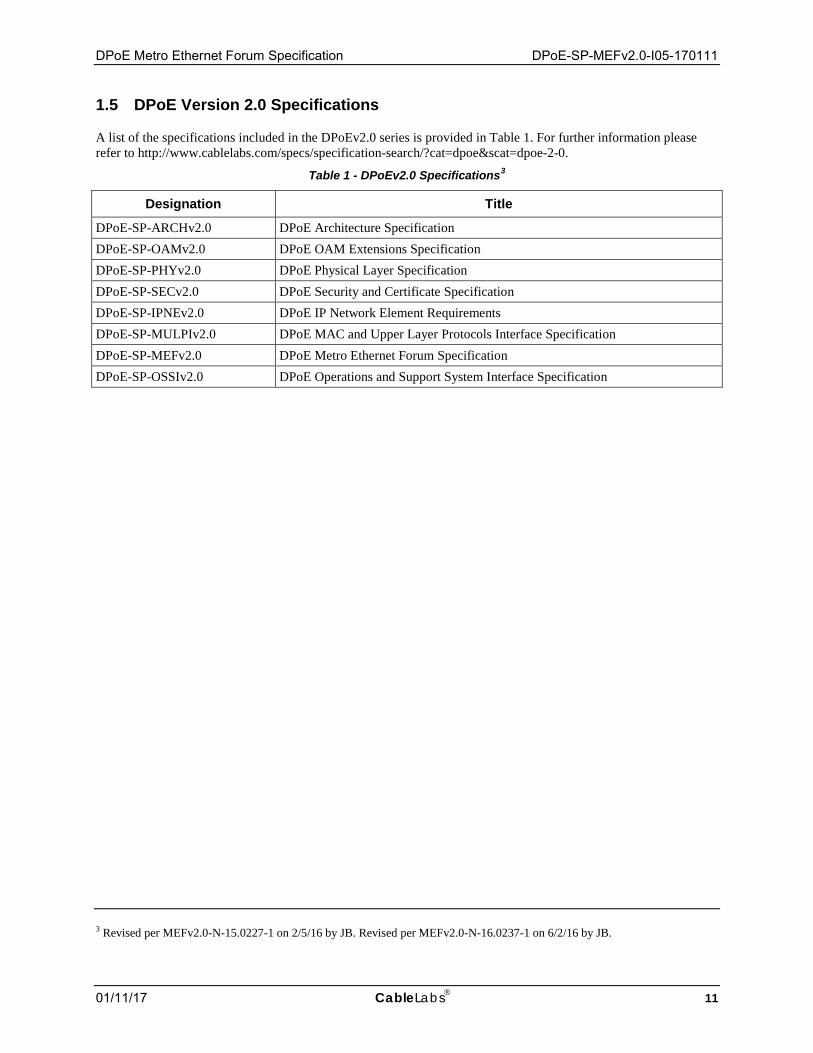
1.5 DPoE Version 2.0 Specifications
A list of the specifications included in the DPoEv2.0 series is provided in Table 1. For further information please refer to http://www.cablelabs.com/specs/specification-search/?cat=dpoe&scat=dpoe-2-0.
Table 1 - DPoEv2.0 Specifications3
Designation Title
DPoE-SP-ARCHv2.0 DPoE Architecture Specification DPoE-SP-OAMv2.0 DPoE OAM Extensions Specification DPoE-SP-PHYv2.0 DPoE Physical Layer Specification DPoE-SP-SECv2.0 DPoE Security and Certificate Specification DPoE-SP-IPNEv2.0 DPoE IP Network Element Requirements DPoE-SP-MULPIv2.0 DPoE MAC and Upper Layer Protocols Interface Specification DPoE-SP-MEFv2.0 DPoE Metro Ethernet Forum Specification DPoE-SP-OSSIv2.0 DPoE Operations and Support System Interface Specification
3 Revised per MEFv2.0-N-15.0227-1 on 2/5/16 by JB. Revised per MEFv2.0-N-16.0237-1 on 6/2/16 by JB.
DPoE-SP-MEFv2.0-I05-170111 DOCSIS® Provisioning of EPON Specifications
12 CableLabs 01/11/17
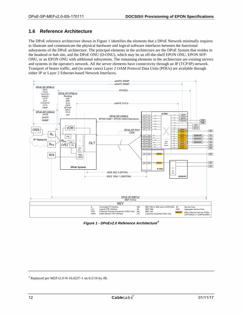
1.6 Reference Architecture
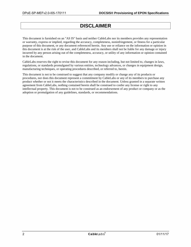
The DPoE reference architecture shown in Figure 1 identifies the elements that a DPoE Network minimally requires to illustrate and communicate the physical hardware and logical software interfaces between the functional subsystems of the DPoE architecture. The principal elements in the architecture are the DPoE System that resides in the headend or hub site, and the DPoE ONU (D-ONU), which may be an off-the-shelf EPON ONU, EPON SFP-ONU, or an EPON ONU with additional subsystems. The remaining elements in the architecture are existing servers and systems in the operator's network. All the server elements have connectivity through an IP (TCP/IP) network. Transport of bearer traffic, and (in some cases) Layer 2 OAM Protocol Data Units (PDUs) are available through either IP or Layer 2 Ethernet-based Network Interfaces.
DPoE-SP-IPNEv2Routing
ARPNDPIS-ISOSPF
MP-BGPMPLSVPLSLDP
X
DPoE System
IP Network RPE(VE)
DPoE-SP-OSSIv2TFTPDHCPSNMP
DPoE-SP-MEFv2MEF EVCs
DPoE-SP-PHYODN
RPE
RP
S-ONU
B-ONU
eDVA
IEEE 802.3 (EPON)
DPoE-SP-IPNEv2SSH2Telnet
TACACS+RADIUS
HTTPNTP
FTP/SFTPTFTPSNMP
OLT
DPoE-SP-OAMv2EPON OAM + EPON OAM Extensions
R/X
OSS
DEMARC
eRouter
IP(HSD)
DEMARC
eSAFE EVCs
XIEEE802.1Switch
DEMARC
sDVA
eWiFi
WiFi
sSAFE SNMPeSAFE SNMP
KEY
IEEE 1904.1 (SIEPON)
MESP
MESP
MESPMESP
MESPMESP
ASF
MESP
MESP
MESP
vCM
LLID
ASFLLID
SFLLID
SFLLID
SFLLID
SFLLID
SFLLID
SFLLID
D Converged IP InterfaceLCI Logical CPE InterfaceCPE Customer Premise Equipment (CMCI only)CMCI Cable Modem CPE Interface
MN MEF NNI or INNI (and L2VPN NSI)MI MEF INNIMU MEF UNICE Customer Equipment (MU only)
SF Service FlowASF Aggregate Service Flow
SF1
SF4
SF1
SF2
SF3
SF5
SF6
SF2
SF3
SF4
SF5
SF6 SF7.1
SF7.2
SF8.1
SF8.2
SF9
SF10.1
SF10.2
SF11
SF12
DEMARCASFLLID SF10.2
ASFLLID SF12
ASFLLID SF10.1+11
ASFLLID SF9
ASFLLID SF8.1+8.2
ASFLLID SF7.1+7.2
SF1
SF2
MESP
IEEE802.1Switch
X
IEEE802.1Switch
PBBI-BEB
CE
CE
CE
CE
CE
CE
CE
CE
CE
CPECPE
MESP
MESP Metro Ethernet Service Profile (OPTIONALLY CONFIGURED
VSIn
VSI2VSI1
Figure 1 - DPoEv2.0 Reference Architecture4
4 Replaced per MEFv2.0-N-16.0237-1 on 6/2/16 by JB.
DPoE Metro Ethernet Forum Specification DPoE-SP-MEFv2.0-I05-170111
01/11/17 CableLabs 13
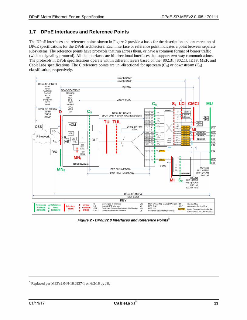
1.7 DPoE Interfaces and Reference Points
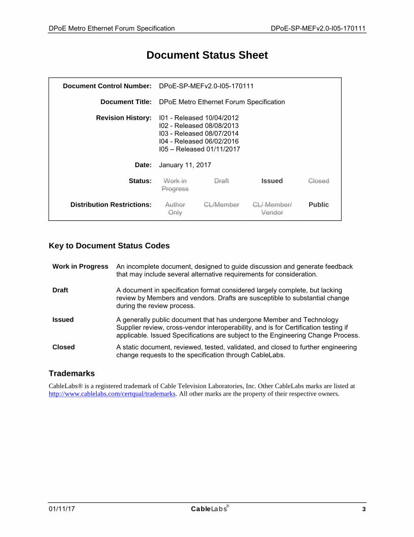
The DPoE interfaces and reference points shown in Figure 2 provide a basis for the description and enumeration of DPoE specifications for the DPoE architecture. Each interface or reference point indicates a point between separate subsystems. The reference points have protocols that run across them, or have a common format of bearer traffic (with no signaling protocol). All the interfaces are bi-directional interfaces that support two-way communications. The protocols in DPoE specifications operate within different layers based on the [802.3], [802.1], IETF, MEF, and CableLabs specifications. The C reference points are uni-directional for upstream (CO) or downstream (CS) classification, respectively.
DPoE-SP-IPNEv2Routing
ARPNDPIS-ISOSPF
MP-BGPMPLSVPLSLDP
X
MI Tags802.1d MAC
802.1q VLAN802.1ad
802.1ah ISID
DPoE System
IP Network RPE(VE)
DPoE-SP-OSSIv2TFTPDHCPSNMP
DPoE-SP-MEFv2MEF EVCs
DPoE-SP-PHYODN
RPE
RP
S-ONU
B-ONU
eDVA
IEEE 802.3 (EPON)
D
TU
DPoE-SP-IPNEv2SSH2Telnet
TACACS+RADIUS
HTTPNTP
FTP/SFTPTFTPSNMP
OLT
DPoE-SP-OAMv2EPON OAM + EPON OAM Extensions
R/X
OSS
MNI
DEMARC
S1
eRouter
IP(HSD)
DEMARC
eSAFE EVCs
XIEEE802.1Switch
LCI
DEMARC
MI
CO
CS
CMCI
sDVA
eWiFi
WiFi
sSAFE SNMPeSAFE SNMP
KEYReference
Point(GREEN)
Interface(RED)
MU
IEEE 1904.1 (SIEPON)
TUL
VirtualInterface
(RED)
MESP
MESP
MESPMESP
MESPMESP
ASF
MESP
MESP
MESP
Reference Interface(GREEN)
vCM
MU Tags802.1d MAC
802.1q VLAN802.1ad
LLID
ASFLLID
SFLLID
SFLLID
SFLLID
SFLLID
SFLLID
SFLLID
D Converged IP InterfaceLCI Logical CPE InterfaceCPE Customer Premise Equipment (CMCI only)CMCI Cable Modem CPE Interface
MN MEF NNI or INNI (and L2VPN NSI)MI MEF INNIMU MEF UNICE Customer Equipment (MU only)
SF Service FlowASF Aggregate Service Flow
SF1
SF4
SF1
SF2
SF3
SF5
SF6
SF2
SF3
SF4
SF5
SF6 SF7.1
SF7.2
SF8.1
SF8.2
SF9
SF10.1
SF10.2
SF11
SF12
DEMARC
4
1
23
5
6
7
8
9
10
1112
ASFLLID SF10.2
ASFLLID SF12
ASFLLID SF10.1+11
ASFLLID SF9
ASFLLID SF8.1+8.2
ASFLLID SF7.1+7.2
CMIM
1
2
SF1
SF2
MESP
IEEE802.1Switch
S2
MNE
X
IEEE802.1Switch
PBBI-BEB
MI
CE
CE
CE
CE
CE
CE
CE
CE
CE
CPECPE
MESP
MESP Metro Ethernet Service Profile (OPTIONALLY CONFIGURED
VSIn
VSI2VSI1
Figure 2 - DPoEv2.0 Interfaces and Reference Points5
5 Replaced per MEFv2.0-N-16.0237-1 on 6/2/16 by JB.

DPoE-SP-MEFv2.0-I05-170111 DOCSIS® Provisioning of EPON Specifications
14 CableLabs 01/11/17
Table 2 - DPoEv2.0 Interface and Reference Point Descriptions
Interface or Reference Point
Interface or Reference Point Description
MN MN is a logical concept used for the specification of requirements for MEF INNI that apply to both MNE and MNI. MN logically provides the equivalent function of a MEF INNI or L2VPN NSI. It is an NNI for Metro Ethernet services only.
MNE The MNE (MEF INNI External) interface is a substitute for the MN reference interface from DPoE version 1.0 specifications. The MN interface is an [802.3] interface for Ethernet (or MEF or L2VPN emulated) services only. It serves the role of a MEF INNI or L2VPN NSI. It is an NNI for Metro Ethernet services only.
MNI The MNI reference interface is used to describe the virtual interface between an OLT and a VPLS Virtual Switch Instance (VSI). In particular, it is used to describe the requirements for stitching VSIs to DPoE System and OLT [802.1] components such as [802.1d] bridge groups, [802.1ad] S-VLAN or C-VLAN (S-component or C-component), or [802.1ad] I-BEB (I-component) or B-BEB (B-component) backbone edge bridges. The DPoE System stitches VPLS and VPWS transport and forwarding for Metro Ethernet Services between the D interface and the MNI reference interface6.
D The D interface is the DOCSIS IP NNI interface. It is an operator network facing interface, sometimes called a Network Systems Interface (NSI) in DOCSIS specifications. The D interface allows a DPoE System to communicate with an IP network. The D interface carries all IP management traffic including OSSI and IP NE traffic. The D interface carries all DOCSIS IP service traffic, IP/MPLS/VPLS traffic, and IP/MPLS/VPWS traffic.
TU The TU interface is a short form of expressing the interface between the DPoE System and the D-ONU.
TUL The TUL interface is a virtual interface representing a logical EPON on an ODN. Each ODN has at least one TUL, and each TUL represents a MAC domain.
C The C reference point is used for explanation of traffic ingress to a DPoE classifier.
CO The CO reference point is used for explanation of traffic ingress to a D-ONU upstream classifier.
CS The CS reference point is used for explanation of traffic ingress to a DPoE System downstream classifier.
S The S interface is an IEEE 802 interface. The S interface may be an internal interface, such as [802.3] across a SERDES (GMII or XGMII) interface in a BP-ONU (such as a SFP-ONU, SFP+ONU or XFP-ONU), or it may be an external Ethernet interface in a BB-ONU or S-ONU. S1 is an interface for an S-ONU. S2 is a reference point used for explanation of services with the B-ONU.
S1 The S1 interfaces are the general case of all interfaces on an S-ONU. S1 interfaces may be CMCI, LCI, MI, or MU interfaces.
S2 The S2 reference point is used for explanation of traffic ingress to and egress from interfaces on a DEMARC device in a DPoE System. Although there are no specifications or requirements for the S2 reference point, informative text refers to the S2 reference point to provide the full context for the use of a B-ONU with a DEMARC device providing Metro Ethernet services.
LCI The Logical CPE Interface (LCI) interface is an eDOCSIS interface as defined in [eDOCSIS]. eSAFEs are connected to LCI interfaces.
CMCI CMCI is the DPoE interface equivalent of the DOCSIS Cable Modem CPE Interface as defined in [CMCIv3.0]. This is the service interface for DOCSIS-based IP services. Customer Premise Equipment (CPE) is connected to CMCI interfaces.
MI MI is an S interface that operates as a MEF INNI with additional requirements as specified in [DPoE-MEFv1.0]. The MI interface is an [802.3] interface (or reference point) between a D-ONU and a DEMARC device.
• A D-ONU that provides a MEF INNI has an MI interface. • A D-ONU can have MU as an interface and an MI reference point on different S interfaces in
a single D-ONU. DEMARC devices are connected to MI interfaces.
6 MNI is required for IP-based forwarding and transport of Metro Ethernet services with DPoE in order to provide MEF E-LAN and E-Tree services described in DPoE version 2.0. While these services can be constructed with MNE, these specifications do not describe the process to do so.
DPoE Metro Ethernet Forum Specification DPoE-SP-MEFv2.0-I05-170111
01/11/17 CableLabs 15
Interface or Reference Point
Interface or Reference Point Description
MU MU is an S interface (or S reference interface) that operates as a MEF UNI. The MU reference interface is an [802.3] interface (or reference point) between a D-ONU or a DEMARC device and a customer's equipment.
• A D-ONU that directly provides a MEF UNI (MU) interface has MU as an interface. • A D-ONU can have MU as an interface and an MI reference point on different S interfaces in
a single D-ONU. Customer Edge (CE) devices are connected to MU interfaces.
DPoE-SP-MEFv2.0-I05-170111 DOCSIS® Provisioning of EPON Specifications
16 CableLabs 01/11/17
2 REFERENCES
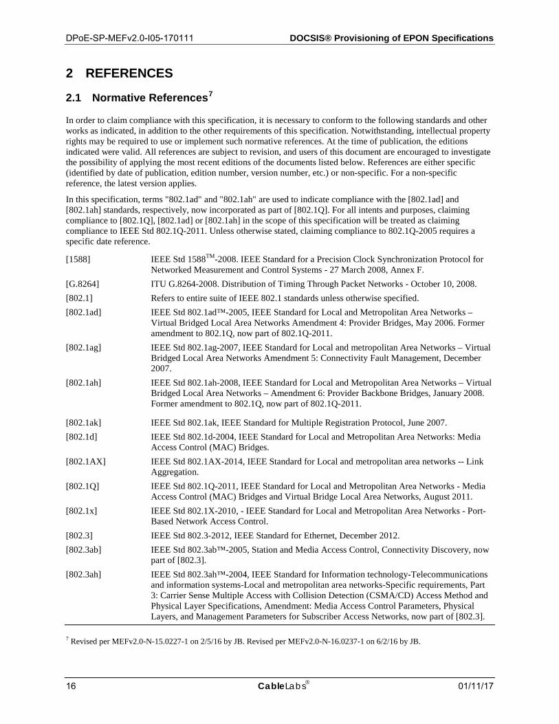
2.1 Normative References7
In order to claim compliance with this specification, it is necessary to conform to the following standards and other works as indicated, in addition to the other requirements of this specification. Notwithstanding, intellectual property rights may be required to use or implement such normative references. At the time of publication, the editions indicated were valid. All references are subject to revision, and users of this document are encouraged to investigate the possibility of applying the most recent editions of the documents listed below. References are either specific (identified by date of publication, edition number, version number, etc.) or non-specific. For a non-specific reference, the latest version applies.
In this specification, terms "802.1ad" and "802.1ah" are used to indicate compliance with the [802.1ad] and [802.1ah] standards, respectively, now incorporated as part of [802.1Q]. For all intents and purposes, claiming compliance to [802.1Q], [802.1ad] or [802.1ah] in the scope of this specification will be treated as claiming compliance to IEEE Std 802.1Q-2011. Unless otherwise stated, claiming compliance to 802.1Q-2005 requires a specific date reference.
[1588] IEEE Std 1588TM-2008. IEEE Standard for a Precision Clock Synchronization Protocol for Networked Measurement and Control Systems - 27 March 2008, Annex F.
[G.8264] ITU G.8264-2008. Distribution of Timing Through Packet Networks - October 10, 2008. [802.1] Refers to entire suite of IEEE 802.1 standards unless otherwise specified. [802.1ad] IEEE Std 802.1ad™-2005, IEEE Standard for Local and Metropolitan Area Networks –
Virtual Bridged Local Area Networks Amendment 4: Provider Bridges, May 2006. Former amendment to 802.1Q, now part of 802.1Q-2011.
[802.1ag] IEEE Std 802.1ag-2007, IEEE Standard for Local and metropolitan Area Networks – Virtual Bridged Local Area Networks Amendment 5: Connectivity Fault Management, December 2007.
[802.1ah] IEEE Std 802.1ah-2008, IEEE Standard for Local and Metropolitan Area Networks – Virtual Bridged Local Area Networks – Amendment 6: Provider Backbone Bridges, January 2008. Former amendment to 802.1Q, now part of 802.1Q-2011.
[802.1ak] IEEE Std 802.1ak, IEEE Standard for Multiple Registration Protocol, June 2007. [802.1d] IEEE Std 802.1d-2004, IEEE Standard for Local and Metropolitan Area Networks: Media
Access Control (MAC) Bridges. [802.1AX] IEEE Std 802.1AX-2014, IEEE Standard for Local and metropolitan area networks -- Link
Aggregation. [802.1Q] IEEE Std 802.1Q-2011, IEEE Standard for Local and Metropolitan Area Networks - Media
Access Control (MAC) Bridges and Virtual Bridge Local Area Networks, August 2011. [802.1x] IEEE Std 802.1X-2010, - IEEE Standard for Local and Metropolitan Area Networks - Port-
Based Network Access Control. [802.3] IEEE Std 802.3-2012, IEEE Standard for Ethernet, December 2012. [802.3ab] IEEE Std 802.3ab™-2005, Station and Media Access Control, Connectivity Discovery, now
part of [802.3]. [802.3ah] IEEE Std 802.3ah™-2004, IEEE Standard for Information technology-Telecommunications
and information systems-Local and metropolitan area networks-Specific requirements, Part 3: Carrier Sense Multiple Access with Collision Detection (CSMA/CD) Access Method and Physical Layer Specifications, Amendment: Media Access Control Parameters, Physical Layers, and Management Parameters for Subscriber Access Networks, now part of [802.3].
7 Revised per MEFv2.0-N-15.0227-1 on 2/5/16 by JB. Revised per MEFv2.0-N-16.0237-1 on 6/2/16 by JB.
DPoE Metro Ethernet Forum Specification DPoE-SP-MEFv2.0-I05-170111
01/11/17 CableLabs 17
[802.3av] IEEE Std 802.3av™-2009, IEEE Standard for Information technology-Telecommunications and information systems-Local and metropolitan area networks-Specific requirements, Part 3: Carrier Sense Multiple Access with Collision Detection (CSMA/CD) Access Method and Physical Layer Specifications Amendment 1: Physical Layer Specifications and Management Parameters for 10Gb/s Passive Optical Networks, now part of [802.3].
[DPoE-ARCHv2.0] DOCSIS Provisioning of EPON, DPoE Architecture Specification, DPoE-SP-ARCHv2.0-I05-160602, June 2, 2016, Cable Television Laboratories, Inc.
[DPoE-IPNEv2.0] DOCSIS Provisioning of EPON, IP Network Element Requirements, DPoE-SP-IPNEv2.0-I06-160602, June 2, 2016, Cable Television Laboratories, Inc.
[DPoE-MEFv1.0] DOCSIS Provisioning of EPON, DPoE Metro Ethernet Forum Specification, DPoE-SP-MEFv1.0-C01-160830, August 30, 2016, Cable Television Laboratories, Inc.
[DPoE-MULPIv1.0] DOCSIS Provisioning of EPON, MAC and Upper Layer Protocols Interface Specification, DPoE-SP-MULPIv1.0-C01-160830, August 30, 2016, Cable Television Laboratories, Inc.
[DPoE-MULPIv2.0] DOCSIS Provisioning of EPON, MAC and Upper Layer Protocols Interface Specification, DPoE-SP-MULPIv2.0-I11-170111, January 11, 2017, Cable Television Laboratories, Inc.
[DPoE-OAMv2.0] DOCSIS Provisioning of EPON, OAM Extensions Specification, DPoE-SP-OAMv2.0-I10-170111, January 11, 2017, Cable Television Laboratories, Inc.
[DPoE-OSSIv2.0] DOCSIS Provisioning of EPON, Operations and Support System Interface Specification, DPoE-SP-OSSIv2.0-I10-170111, January 11, 2017, Cable Television Laboratories, Inc.
[DPoE-PHYv2.0] DOCSIS Provisioning of EPON, Physical Layer Specification, DPoE-SP-PHYv2.0-I05-160602, June 2, 2016, Cable Television Laboratories, Inc.
[DPoE-SECv2.0] DOCSIS Provisioning of EPON, Security and Certificate Specification, DPoE-SP-SECv2.0-I05-160602, June 2, 2016, Cable Television Laboratories, Inc.
[L2VPN] Data-Over-Cable Service Interface Specifications, Layer 2 Virtual Private Networks, CM-SP-L2VPN-I15-150528, May 28, 2015, Cable Television Laboratories, Inc.
[MEF 6.1] Metro Ethernet Forum, MEF 6.1 Ethernet Services Definitions, Phase 2, April 2008. [MEF 10.2] Metro Ethernet Forum, Ethernet Services Attributes – Phase 2, October 2009. [MEF 10.2.1] Metro Ethernet Forum Performance Attributes Amendment to MEF 10.2, January 2011. [MEF 13] Metro Ethernet Forum User Network Interface Type 1 Implementation Agreement,
November 2005. [MEF 16] Metro Ethernet Forum Ethernet Local Management Interface (E-LMI), January 2006.
2.2 Informative References8
This specification uses the following informative references.
[802.1AB] IEEE Std 802.1AB-2009, IEEE Standard for Local and Metropolitan Area Networks - Station and Media Access Control Connectivity Discovery.
[802.1q-2005] IEEE Std 802.1q-2005, IEEE Standard for Local and Metropolitan Area Networks-Virtual Bridged Local Area Networks, January 2010.
[CMCIv3.0] Data-Over-Cable Service Interface Specifications, Cable Modem to Customer Premise Equipment Interface Specification, CM-SP-CMCIv3.0-C01-081104, November 4, 2008, Cable Television Laboratories, Inc.
[DOCSIS] Refers to entire suite of DOCSIS 3.0 specifications unless otherwise specified. [eDOCSIS] Data-Over-Cable Service Interface Specifications, eDOCSIS Specification, CM-SP-eDOCSIS-I28-
150305, March 5, 2015, Cable Television Laboratories, Inc. 8 Revised per MEFv2.0-N-15.0227-1 on 2/5/16 by JB.
DPoE-SP-MEFv2.0-I05-170111 DOCSIS® Provisioning of EPON Specifications
18 CableLabs 01/11/17
[G.805] ITU-T Recommendation G.805 (03/2000), Generic functional architecture of transport networks. [MEF 4] Metro Ethernet Forum, Metro Ethernet Network Architecture Framework – Part 1: generic
Framework, May 2004. [MEF 7.1] Metro Ethernet Forum, Phase 2 EMS-NMS Information Model, October, 2009. [MEF 9] Metro Ethernet Forum, Abstract Test Suite for Ethernet Services at the UNI, October 2004. [MEF 14] Metro Ethernet Forum, Abstract Test Suite for Traffic Management Phase 1, November 2005. [MEF 26] Metro Ethernet Forum, External Network to Network Interface (ENNI) – Phase 1, January 2010. [MEF 30] Metro Ethernet Forum, MEF 30 Service OAM Fault Management Implementation Agreement,
January 2011. [MULPIv3.0] Data-Over-Cable Service Interface Specifications, MAC and Upper Layer Protocols Interface
Specification, CM-SP-MULPIv3.0-I30-170111, January 11, 2017, Cable Television Laboratories, Inc.
[OSSIv3.0] Data-Over-Cable Service Interface Specifications, Operations Support System Interface Specification, CM-SP-OSSIv3.0-I30-170111, January 11, 2017, Cable Television Laboratories, Inc.
[Q.840.1] ITU-T Recommendation Q.840.1 (03/2007), Requirements and Analysis for NMS-EMS Management Interface of Ethernet over Transport and Metro Ethernet Network (EoT/MEN).
[RFC 2338] IETF RFC 2338, Virtual Router Redundancy Protocol, April 1998. [RFC 2863] IETF RFC 2863, The Interfaces Group MIB, June 2000. [RFC 4115] IETF RFC 4115, A Differentiated Service Two-Rate, Three-Color Marker with Efficient Handling
of in-Profile Traffic, July 2005. [RFC 4364] IETF RFC 4364, BGP/MPLS IP Virtual Private Networks (VPNs), February 2006. [SCTE 174] ANSI/SCTE 174 2010, Radio Frequency over Glass Fiber-to-the-Home Specification.
2.3 Reference Acquisition
• Cable Television Laboratories, Inc., 858 Coal Creek Circle, Louisville, CO 80027; Phone +1-303-661-9100; Fax +1-303-661-9199; http://www.cablelabs.com
• Internet Engineering Task Force (IETF) Secretariat, 48377 Fremont Blvd., Suite 117, Fremont, California 94538, USA, Phone: +1-510-492-4080, Fax: +1-510-492-4001, http://www.ietf.org
• Institute of Electrical and Electronics Engineers (IEEE), +1 800 422 4633 (USA and Canada); http://www.ieee.org
• ITU: International Telecommunications Union (ITU), http://www.itu.int/home/contact/index.html
• Metro Ethernet Forum, 6033 W. Century Blvd, Suite 830, Los Angeles, CA 90045 Phone +1-310-642-2800; Fax +1-310-642-2808. Internet: http://metroethernetforum.org
• Telecommunication Standardization Sector of the International Telecommunication Union (ITU-T), Place des Nations, CH-1211, Geneva 20, Switzerland; Phone +41-22-730-51-11; Fax +41-22-733-7256. Internet: http://www.itu.int
• SCTE, Society of Cable Telecommunications Engineers Inc., 140 Philips Road, Exton, PA 19341 Phone: +1-800-542-5040, Fax: +1-610-363-5898, Internet: http://www.scte.org/
DPoE Metro Ethernet Forum Specification DPoE-SP-MEFv2.0-I05-170111
01/11/17 CableLabs 19
3 TERMS AND DEFINITIONS
3.1 DPoE Network Elements9
DPoE Network This term means all the elements of a DPoE implementation, including at least one DPoE System, and one or more D-ONUs connected to that DPoE System.
DPoE System
This term refers to the set of subsystems within the hub site that provides the functions necessary to meet DPoE specification requirements.
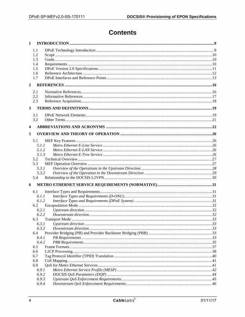
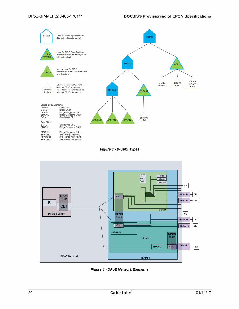
DPoE ONU (D-ONU) This term means a DPoE-capable ONU that complies with all the DPoE specifications. There are two logical types of D-ONUs. These are the DPoE Standalone ONU (S-ONU) and the DPoE Bridge ONU (B-ONU). Requirements specified for a D-ONU must be met by all ONUs.
DPoE Standalone ONU (S-ONU)
This term means a D-ONU that provides all the functions of a B-ONU and also provides at least one CMCI port. An S-ONU can optionally have one or more eSAFEs.
DPoE Bridge ONU (B-ONU) This term means a D-ONU that is capable of [802.1] forwarding but cannot do all the encapsulation functions required to be an S-ONU. The B-ONU is a logical definition used by the specification for requirements that apply to all types of B-ONUs. The two types of B-ONUs are the BP-ONU and the BB-ONU.
DPoE Bridge Pluggable ONU (BP-ONU)
This term means a D-ONU that is a B-ONU which is pluggable. Pluggable BP-ONUs include devices such as an SFP-ONU (1G-EPON), SFP+ONU (10G-EPON), or XFP-ONU (10G-EPON).
DPoE Bridge Baseband ONU (BB-ONU)
This term means a D-ONU that is a B-ONU which has a baseband IEEE Ethernet interface. BB-ONUs include those with one or more [802.3] baseband PMDs. (See [DPoE-ARCHv2.0], section 7.2.6.2 for examples.)
DEMARC Short form of "Demarcation Device." This term means the device, owned and operated by the operator that provides the demarcation (sometimes called the UNI interface) to the customer. Some architectures describe this device as the CPE (as in DOCSIS) or the NID (as in the MEF model).
9 Revised per MEFv2.0-N-15.0227-1 on 2/5/16 by JB.
DPoE-SP-MEFv2.0-I05-170111 DOCSIS® Provisioning of EPON Specifications
20 CableLabs 01/11/17
Product
Logical D-ONU
B-ONU S-ONU
SFP-ONU
BP-ONU
SFP+ONU XFP-ONU
S-ONU+eSAFEs
S-ONU+.1ah
S-ONU+eSAFE
+.1ahProductOptions
Logical DPoE ElementsD-ONU DPoE ONUB-ONU Bridge ONUBP-ONU Bridge Pluggable ONUBB-ONU Bridge Baseband ONUS-ONU Standalone ONU
Real ONUsS-ONU Standalone ONUBB-ONU Bridge Baseband ONU
BP-ONU Bridge Pluggable ONUsSFP-ONU SFP ONU (1G-EPON)SFP+ONU SFP+ ONU (10G-EPON)XFP-ONU XFP-ONU (10G-EPON)
Used for DPoE Specifications (Normative Requirements)
May be used for DPoE informative, but not for normative specifications.
Likely products. MUST not be used for DPoE normative (specifications). Should not be used for DPoE informative.
Logical+ Product
Used for DPoE Specifications(Normative Requirements) or for informative text.
BB-ONU
BB-ONU+.1ah
Figure 3 - D-ONU Types
DPoE System
R
ONU
X
S-ONU
BB-ONU
eDVA
OLT
ONU
eRouter
DEMARC
IEEE802.1Switch
DEMARC
WiFi
D-ONU
EPONCHIP
EPONCHIP
ONUBP-ONU DEMARC
B-ONUEPONCHIP
DPoE Network
DEMARC
CE
CE
CE
CE
CE
CE
DEMARC CE
Figure 4 - DPoE Network Elements
DPoE Metro Ethernet Forum Specification DPoE-SP-MEFv2.0-I05-170111
01/11/17 CableLabs 21
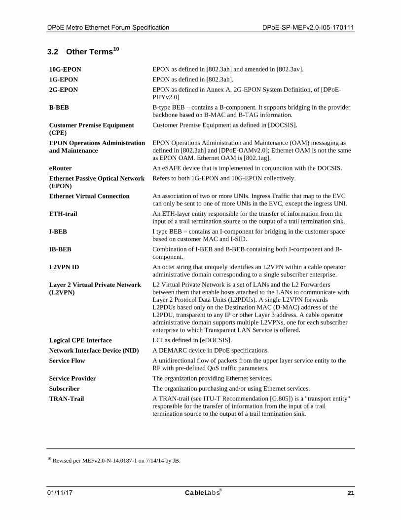
3.2 Other Terms10
10G-EPON EPON as defined in [802.3ah] and amended in [802.3av]. 1G-EPON EPON as defined in [802.3ah]. 2G-EPON EPON as defined in Annex A, 2G-EPON System Definition, of [DPoE-
PHYv2.0] B-BEB B-type BEB – contains a B-component. It supports bridging in the provider
backbone based on B-MAC and B-TAG information. Customer Premise Equipment (CPE)
Customer Premise Equipment as defined in [DOCSIS].
EPON Operations Administration and Maintenance
EPON Operations Administration and Maintenance (OAM) messaging as defined in [802.3ah] and [DPoE-OAMv2.0]; Ethernet OAM is not the same as EPON OAM. Ethernet OAM is [802.1ag].
eRouter An eSAFE device that is implemented in conjunction with the DOCSIS. Ethernet Passive Optical Network (EPON)
Refers to both 1G-EPON and 10G-EPON collectively.
Ethernet Virtual Connection An association of two or more UNIs. Ingress Traffic that map to the EVC can only be sent to one of more UNIs in the EVC, except the ingress UNI.
ETH-trail An ETH-layer entity responsible for the transfer of information from the input of a trail termination source to the output of a trail termination sink.
I-BEB I type BEB – contains an I-component for bridging in the customer space based on customer MAC and I-SID.
IB-BEB Combination of I-BEB and B-BEB containing both I-component and B-component.
L2VPN ID An octet string that uniquely identifies an L2VPN within a cable operator administrative domain corresponding to a single subscriber enterprise.
Layer 2 Virtual Private Network (L2VPN)
L2 Virtual Private Network is a set of LANs and the L2 Forwarders between them that enable hosts attached to the LANs to communicate with Layer 2 Protocol Data Units (L2PDUs). A single L2VPN forwards L2PDUs based only on the Destination MAC (D-MAC) address of the L2PDU, transparent to any IP or other Layer 3 address. A cable operator administrative domain supports multiple L2VPNs, one for each subscriber enterprise to which Transparent LAN Service is offered.
Logical CPE Interface LCI as defined in [eDOCSIS]. Network Interface Device (NID) A DEMARC device in DPoE specifications. Service Flow A unidirectional flow of packets from the upper layer service entity to the
RF with pre-defined QoS traffic parameters. Service Provider The organization providing Ethernet services. Subscriber The organization purchasing and/or using Ethernet services. TRAN-Trail A TRAN-trail (see ITU-T Recommendation [G.805]) is a "transport entity"
responsible for the transfer of information from the input of a trail termination source to the output of a trail termination sink.
10 Revised per MEFv2.0-N-14.0187-1 on 7/14/14 by JB.
DPoE-SP-MEFv2.0-I05-170111 DOCSIS® Provisioning of EPON Specifications
22 CableLabs 01/11/17
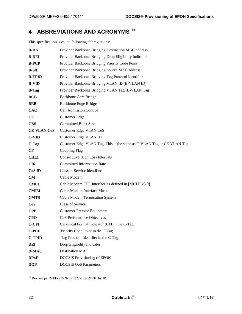
4 ABBREVIATIONS AND ACRONYMS 11 This specification uses the following abbreviations:
B-DA Provider Backbone Bridging Destination MAC address
B-DEI Provider Backbone Bridging Drop Eligibility Indicator
B-PCP Provider Backbone Bridging Priority Code Point
B-SA Provider Backbone Bridging Source MAC address
B-TPID Provider Backbone Bridging Tag Protocol Identifier
B-VID Provider Backbone Bridging VLAN ID (B-VLAN ID)
B-Tag Provider Backbone Bridging VLAN Tag (B-VLAN Tag)
BCB Backbone Core Bridge
BEB Backbone Edge Bridge
CAC Call Admission Control
CE Customer Edge
CBS Committed Burst Size
CE-VLAN CoS Customer Edge VLAN CoS
C-VID Customer Edge VLAN ID
C-Tag Customer Edge VLAN Tag. This is the same as C-VLAN Tag or CE-VLAN Tag
CF Coupling Flag
CHLI Consecutive High Loss Intervals
CIR Committed Information Rate
CoS ID Class of Service Identifier
CM Cable Modem
CMCI Cable Modem CPE Interface as defined in [MULPIv3.0]
CMIM Cable Modem Interface Mask
CMTS Cable Modem Termination System
CoS Class of Service
CPE Customer Premise Equipment
CPO CoS Performance Objectives
C-CFI Canonical Format Indicator (CFI)in the C-Tag
C-PCP Priority Code Point in the C-Tag
C-TPID Tag Protocol Identifier in the C-Tag
DEI Drop Eligibility Indicator
D-MAC Destination MAC
DPoE DOCSIS Provisioning of EPON
DQP DOCSIS QoS Parameters
11 Revised per MEFv2.0-N-15.0227-1 on 2/5/16 by JB.
DPoE Metro Ethernet Forum Specification DPoE-SP-MEFv2.0-I05-170111
01/11/17 CableLabs 23
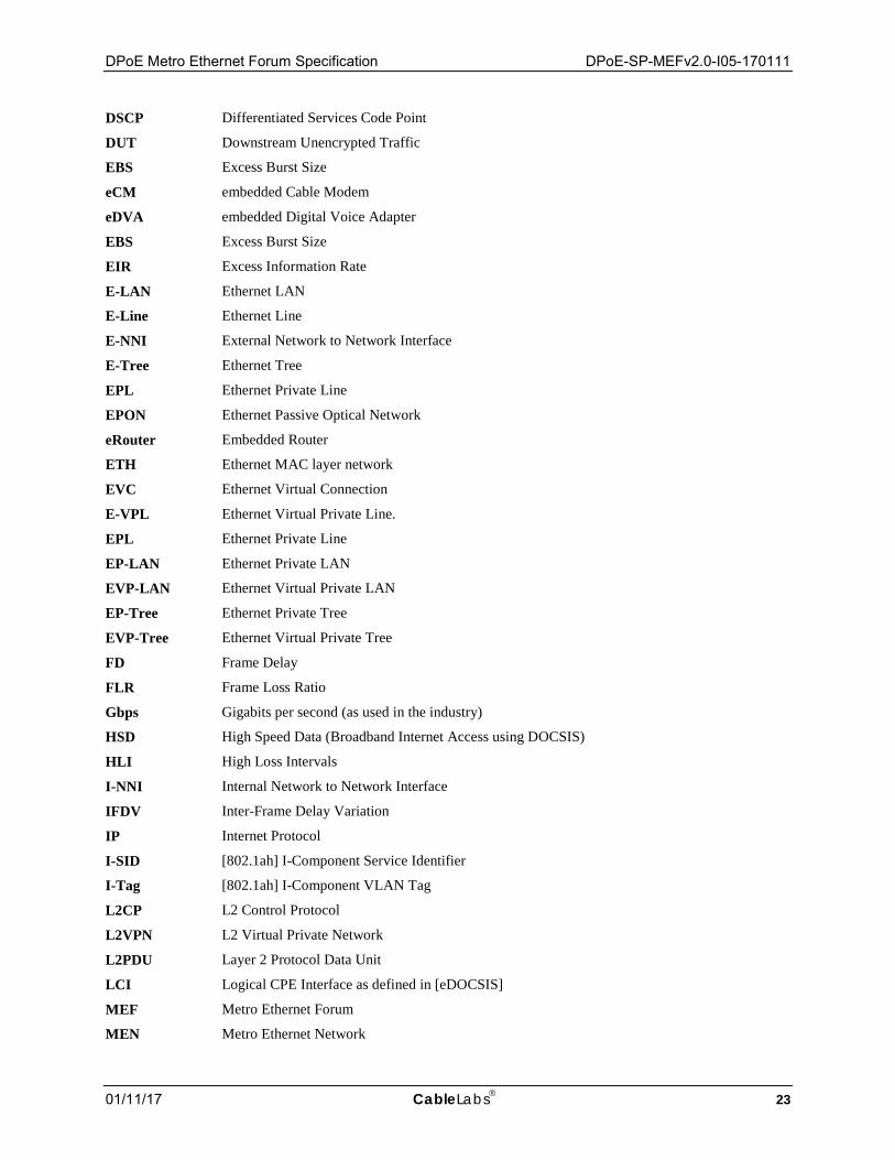
DSCP Differentiated Services Code Point
DUT Downstream Unencrypted Traffic
EBS Excess Burst Size
eCM embedded Cable Modem
eDVA embedded Digital Voice Adapter
EBS Excess Burst Size
EIR Excess Information Rate
E-LAN Ethernet LAN
E-Line Ethernet Line
E-NNI External Network to Network Interface
E-Tree Ethernet Tree
EPL Ethernet Private Line
EPON Ethernet Passive Optical Network
eRouter Embedded Router
ETH Ethernet MAC layer network
EVC Ethernet Virtual Connection
E-VPL Ethernet Virtual Private Line.
EPL Ethernet Private Line
EP-LAN Ethernet Private LAN
EVP-LAN Ethernet Virtual Private LAN
EP-Tree Ethernet Private Tree
EVP-Tree Ethernet Virtual Private Tree
FD Frame Delay
FLR Frame Loss Ratio
Gbps Gigabits per second (as used in the industry)
HSD High Speed Data (Broadband Internet Access using DOCSIS)
HLI High Loss Intervals
I-NNI Internal Network to Network Interface
IFDV Inter-Frame Delay Variation
IP Internet Protocol
I-SID [802.1ah] I-Component Service Identifier
I-Tag [802.1ah] I-Component VLAN Tag
L2CP L2 Control Protocol
L2VPN L2 Virtual Private Network
L2PDU Layer 2 Protocol Data Unit
LCI Logical CPE Interface as defined in [eDOCSIS]
MEF Metro Ethernet Forum
MEN Metro Ethernet Network
DPoE-SP-MEFv2.0-I05-170111 DOCSIS® Provisioning of EPON Specifications
24 CableLabs 01/11/17
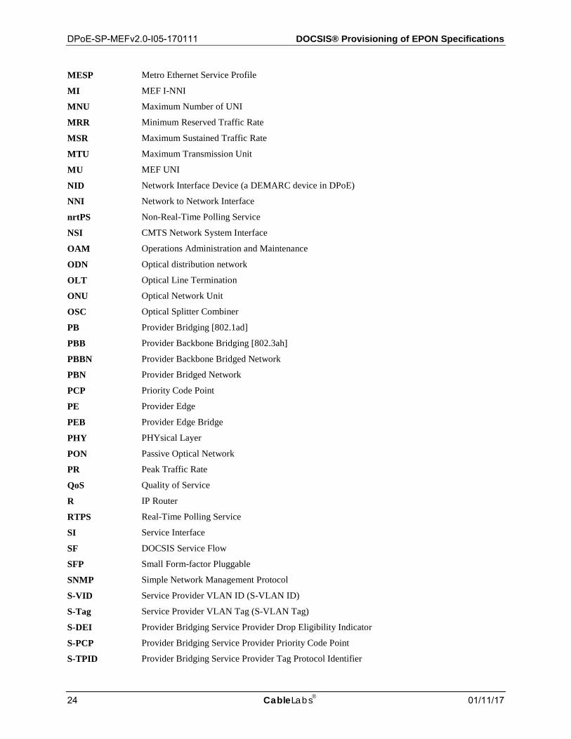
MESP Metro Ethernet Service Profile
MI MEF I-NNI
MNU Maximum Number of UNI
MRR Minimum Reserved Traffic Rate
MSR Maximum Sustained Traffic Rate
MTU Maximum Transmission Unit
MU MEF UNI
NID Network Interface Device (a DEMARC device in DPoE)
NNI Network to Network Interface
nrtPS Non-Real-Time Polling Service
NSI CMTS Network System Interface
OAM Operations Administration and Maintenance
ODN Optical distribution network
OLT Optical Line Termination
ONU Optical Network Unit
OSC Optical Splitter Combiner
PB Provider Bridging [802.1ad]
PBB Provider Backbone Bridging [802.3ah]
PBBN Provider Backbone Bridged Network
PBN Provider Bridged Network
PCP Priority Code Point
PE Provider Edge
PEB Provider Edge Bridge
PHY PHYsical Layer
PON Passive Optical Network
PR Peak Traffic Rate
QoS Quality of Service
R IP Router
RTPS Real-Time Polling Service
SI Service Interface
SF DOCSIS Service Flow
SFP Small Form-factor Pluggable
SNMP Simple Network Management Protocol
S-VID Service Provider VLAN ID (S-VLAN ID)
S-Tag Service Provider VLAN Tag (S-VLAN Tag)
S-DEI Provider Bridging Service Provider Drop Eligibility Indicator
S-PCP Provider Bridging Service Provider Priority Code Point
S-TPID Provider Bridging Service Provider Tag Protocol Identifier
DPoE Metro Ethernet Forum Specification DPoE-SP-MEFv2.0-I05-170111
01/11/17 CableLabs 25
TCA Threshold Crossing Alert
TLS Transparent LAN Service
TOS Type of Service byte in the IPv4 header
TPID Tag Protocol Identifier
TRANS Transport Services
UGS Unsolicited Grant Service
UGS-AD Unsolicited Grant Service with Activity Detection
UNI User Network Interface
VE VPLS Edge
VLAN Virtual Local Area Network
VPN Virtual Private Network
VPNID VPN Identifier
VSI Virtual Switch Instance
XFP X Form-factor Pluggable

DPoE-SP-MEFv2.0-I05-170111 DOCSIS® Provisioning of EPON Specifications
26 CableLabs 01/11/17
5 OVERVIEW AND THEORY OF OPERATION
5.1 MEF Key Features
This specification includes support for the following Metro Ethernet services and the associated service attributes (e.g., Bandwidth Profile) as defined in [MEF 6.1] and [MEF 10.2].
• E-Line including EPL and EVPL.
• E-LAN including EP-LAN and EVP-LAN.
• E-Tree including EP-Tree and EVP-Tree.
This specification includes support for the following MEF interfaces.
• UNI including UNI Type 1.1 and 1.2 as defined in [MEF 13]
• I-NNI as defined in [MEF 4].
Metro Ethernet E-Line Service 5.1.1An E-Line service provides transparent Layer 2 connectivity between two endpoints. In a DPoE Network, these end points can be located anywhere in the network. Some examples of their location include:
• Endpoints are located on two different D-ONUs connected to a single TUL interface.
• Endpoints are located on two different D-ONUs connected to two different TUL interfaces on a single DPoE System.
• Endpoints are located on two different D-ONUs connected to two different DPoE Systems that may be located right next to each other or thousands of miles apart.
• One endpoint is located on a D-ONU in a DPoE Network and the other endpoint is located in a non-DPoE Network (e.g., DOCSIS, WDM).
Metro Ethernet E-LAN Service 5.1.2
An E-LAN service provides transparent Layer 2 connectivity between two or more endpoints. In a DPoE Network, these end points can be located anywhere in the network. Some examples of their location include:
• One or more endpoints are located on separate D-ONUs that are connected to the same DPoE System.
• One or more endpoints are located on D-ONUs that are connected to different DPoE Systems.
• One or more endpoints are located in a non-DPoE Network (e.g., DOCSIS, WDM).
Metro Ethernet E-Tree Service 5.1.3
An E-Tree service defines two types of endpoints: 1) root, and 2) leaf, and provides transparent Layer 2 connectivity between two or more of these endpoints where a leaf is not allowed to directly communicate with other leaf. In a DPoE Network, these end points can be located anywhere in the network. Some examples of their location include:
• One or more endpoints (root or leaf) are located on separate D-ONUs that are connected to the same DPoE System.
• One or more endpoints (root or leaf) are located on D-ONUs that are connected to different DPoE Systems.
• One or more endpoints (root or leaf) are located in a non-DPoE Network (e.g., DOCSIS, WDM).
DPoE Metro Ethernet Forum Specification DPoE-SP-MEFv2.0-I05-170111
01/11/17 CableLabs 27
5.2 Technical Overview
Metro Ethernet service is one of the many services that can be offered on the DPoE Network. A comprehensive list of these services is provided in the [DPoE-ARCHv2.0] specification. Metro Ethernet service, in many ways, is similar to and uses some of the same concepts as the IP(HSD) and L2VPN services as defined in [DPoE-MULPIv2.0] and [L2VPN] respectively. As a result, this specification employs the following concepts from [DPoE-MULPIv2.0] and [L2VPN] to enable Metro Ethernet services in a DPoE Network:
• Classification process, as defined in [DPoE-MULPIv2.0].
• Provider Bridging (PB) Forwarding as defined in [DPoE-MULPIv2.0].
• Provider Backbone Bridging (PBB) forwarding as defined in [DPoE-MULPIv2.0].
• Quality of Service (QoS) using Service Flow (SF), and Aggregate Service Flow (ASF) as defined in [DPoE-MULPIv2.0].
• Encapsulation using [L2VPN] encoding TLVs.
While similar to IP(HSD) and L2VPN in many ways, there are aspects of Metro Ethernet services that are unique. As a consequence, this specification, in addition to drawing on the concepts defined in [L2VPN] and [DPoE-MULPIv2.0] specifications, defines the following concepts and related requirements:
• Encapsulation and Transport Mode as defined in Sections 6.2 and 6.3 respectively.
• Encapsulation based on [802.1ah]. Encapsulation using [802.1ah] is new in DPoE specifications since [L2VPN] currently only defines encapsulation based on 802.1q, 802.1ad, L2TPv3, and MPLS. Even though encapsulation based on L2TPv3 is supported in [L2VPN], the current [DPoE-MEFv1.0] specification currently does not include any L2TPv3 encapsulation requirements on either DPoE System or D-ONU. The usage of MPLS in the DPoE Network is described in section 8 of [DPoE-ARCHv2.0].
• Procedures and requirements for [802.1ad] tagging and [802.1ah] encapsulation by the D-ONU. While this specification employs NSI encapsulation TLVs defined in [L2VPN] to add necessary tagging and encapsulation, this step of tagging and encapsulation takes place at the D-ONU and not at the DPoE System. This is different from [L2VPN] since in [L2VPN] all the tagging and encapsulation is done at the CMTS and not Cable Modem. Section 6 provides further details on how tagging and encapsulation are applied at the D-ONU. The details on encapsulation (e.g., MPLS) applied at the DPoE System are covered in the [DPoE-ARCHv2.0] specification.
• Ethernet TPID translation as defined in Section 6.7. This specification defines extended TPID translation functionality, which was not part of the DPoEv1.0 specifications.
• MESP to define QoS attribute for Metro Ethernet services. The MESP is defined in Section 6.9.
• Metro Ethernet service usage accounting requirements as defined in Section 7.
• Layer 2 Control Protocol (L2CP) message processing as defined in Section 6.6.
5.3 MEF Operation Overview
The procedures explained in this section are for information purpose only. The products are not required to demonstrate or follow these steps strictly as long as the requirements in the normative sections of this specification are met.
DPoE-SP-MEFv2.0-I05-170111 DOCSIS® Provisioning of EPON Specifications
28 CableLabs 01/11/17
Overview of the Operations in the Upstream Direction 5.3.1
In the upstream direction, a D-ONU receives Ethernet frames either directly from a Customer Edge (CE) device or a DEMARC. There are a number of steps that takes place at the D-ONU and DPoE System to successfully receive the frames from CE or DEMARC and forward them on the MN (MNE and MNI) interface. These steps are summarized as follows.
• Classification:
1. Classification at the D-ONU: The D-ONU classifies ingress Ethernet frames, received from the CE or DEMARC, based on the D-ONU interface over which the frames are received and a number of L2/L3/L4 fields and subfields, as provisioned by the operator. The process of classification identifies an SF for the Ethernet frames, and the SF subsequently can be used to identify the [L2VPN] encoding and (optionally) the ASF. The SF and ASF information is used for QoS and forwarding and the [L2VPN] encoding is used for Metro Ethernet service instance identification and marking. The classification requirements and TLVs used to provision classification criterion are defined in [DPoE-MULPIv2.0].
2. Classification at the DPoE System: Similar to D-ONU, the DPoE System performs the classification function to identify the Metro Ethernet service instance and forward the frames to the correct MNE, or MNI and VSI instance or Pseudowire forwarder. The details on how an Ethernet frame is mapped to the correct VPLS Virtual Switch Instance (VSI) and how the frames are forwarded by the VSI are provided in [DPoE-ARCHv2.0].
• Encapsulation: In the DPoE Network, this step can takes place at the DEMARC, D-ONU, and DPoE System. This specification only focuses on the encapsulation applied at the D-ONU. The procedures and requirements for MPLS encapsulation applied at the DPoE System are provided in [DPoE-ARCHv2.0]. The procedures and requirements for encapsulation applied at the DEMARC are out of scope of DPoE specifications. The D-ONU uses the [L2VPN] encoding and extension thereof defined in this specification to add the service identification tags (e.g., [802.1ad]) or encapsulation (e.g., [802.1ah]), which are primarily used to identify a spoke of Metro Ethernet service instance and forwarding in the DPoE Network. The D-ONU performs the encapsulation function only when a Service Interface (SI) is provisioned in the Encapsulation Mode. The concept of Service Interface is defined in [DPoE-ARCHv2.0]. The D-ONU does not perform the encapsulation function when an SI is provisioned in the Transport Mode. The mode of operation (Transport Mode vs. Encapsulation Mode) is provisioned using [L2VPN] encoding. The D-ONU can be configured to work in the Encapsulation and Transport Mode at the same time for different SIs. In the Transport Mode, the D-ONU forwards frames towards the TUL interface without adding any tagging or encapsulation.
• Enforcement of Quality of Service (QoS): D-ONU and DPoE System together are responsible for the execution of this function. The concept of SF and ASF, as defined in [DPoE-MULPIv2.0], is at the core of how QoS is implemented in the DPoE Network. The DPoE Network allows each Metro Ethernet Service instance to have associated QoS parameters (e.g., MESP), which are used by the DPoE System and D-ONU to allocate necessary bandwidth and apply other QoS treatment (e.g., mark color) in the Ethernet frames. The DPoE Network also allows configuration of separate QoS for different Class of Service (CoS) within a Metro Ethernet service instance. These QoS parameters and associated requirements are defined in Section 6.9 of this document. The QoS requirements in this document are limited in scope as they apply to Metro Ethernet services only. QoS for Metro Ethernet services as defined in this specification focuses on the DPoE Network between the reference points C0 and CS. The QoS requirements for other services (e.g., IP(HSD)) are defined in [DPoE-MULPIv2.0].
• Forwarding: This step is divided into two sub steps: 1) forwarding by the D-ONU and 2) forwarding by the DPoE System.
1. Forwarding by the D-ONU: The D-ONU performs classification, encapsulation, and QoS enforcement steps as described above and forwards Ethernet frames to the DPoE System using the LLID assigned to the Metro Ethernet service instance. While this specification provides details on how Ethernet frames belonging to a Metro Ethernet service instance are mapped to an SF and ASF, the details on how an SF or ASF are mapped to an LLID are provided in [DPoE-MULPIv2.0].
DPoE Metro Ethernet Forum Specification DPoE-SP-MEFv2.0-I05-170111
01/11/17 CableLabs 29
2. Forwarding by the DPoE System: The DPoE System receives Ethernet frames and identifies the Metro Ethernet service instance by using classification as described above. Subsequently, the DPoE System forwards frames to either MNI or MNE interface. The details on how an Ethernet frame is mapped to the correct VPLS Virtual Switch Instance (VSI) and how the frames are forwarded by the VSI are provided in [DPoE-ARCHv2.0].
• TPID Translation: This optional step takes place at the DPoE System. Before Ethernet frames are forwarded to the MN interface, the DPoE System, if configured, may perform applicable TPID translation. This step is performed only when the [L2VPN] encoding TLVs for TPID translation are provisioned.
• CoS Mapping: The CoS mapping is used to map customer CoS values in the incoming tagged frame to the Service Provider CoS Value in the Service Provider added tag, which also includes mapping of the CoS values from one protocol to another. (e.g., S-Tag PCP to MPLS Traffic Class). In the upstream direction, the CoS mapping can take place either on the D-ONU, DPoE System, or both. Section 6.8 of this document provides necessary details and requirements to support CoS mapping functionality.
Overview of the Operation in the Downstream Direction 5.3.2
In the downstream direction, the DPoE System receives Ethernet frames either from the MNI, MNE, or D interface. In either case there are a number of steps that take place at the DPoE System and D-ONU before the frames are delivered to the DEMARC or CE. These steps are summarized as follows:
• Classification: Both D-ONU and DPoE System employ classification as described below.
1. Classification by the DPoE System: The DPoE System classifies ingress Ethernet frames, received from the MN interface, based on a number of L2/L3/L4 fields and subfields, as provisioned by the operator. The process of classification identifies an SF for Ethernet frames and (optionally) the SF subsequently identifies the ASF.
2. Classification by the D-ONU: This specification allows frames from multiple Metro Ethernet service instances to be multiplexed into a single LLID. Hence the LLID, used to transport the frames, cannot be used alone to determine individual Metro Ethernet service instances. The D-ONU may use the provisioned classifiers and [L2VPN] encodings in addition to the LLID to identify the Metro Ethernet service instance and subsequently the egress physical port.
• TPID Translation: Similar to the TPID translation step in the upstream direction, this optional step takes place at the DPoE System. Before Ethernet frames are forwarded to the TUL interface, the DPoE System, if configured, may perform applicable TPID translation. This step is performed only when the [L2VPN] encoding TLVs for downstream TPID translation are provisioned.
• Enforcement of Quality of Service (QoS): The DPoE System is responsible for the execution of this step. Each Metro Ethernet Service instance can have associated QoS parameters (e.g., MESP), which are used by the DPoE System to allocate necessary bandwidth and apply other QoS treatment (e.g., mark color) to Ethernet frames. These QoS parameters and associated requirements are defined in Section 6.9.
• Forwarding: The DPoE System and D-ONU forward frames as described below.
1. Forwarding by the DPoE System: The DPoE System uses provisioned classifiers and tags (e.g., [802.1ad] or [802.1ah]) in the frames to identify the SF and (optionally) ASF to forward the frames to the correct D-ONU.
2. Forwarding by the D-ONU: The D-ONU receives Ethernet frames from the TUL interface in the context of Metro Ethernet service instance by using the information such as tags (e.g., [802.1ad], [802.1ah]) and provisioned classifiers and [L2VPN] encoding. Subsequently, the D-ONU forwards frames to the MU or MI interface associated with the given Metro Ethernet service instance.
• De-encapsulation: This step is only executed on frames that belong to a Metro Ethernet service instance provisioned in the Encapsulation Mode. In this case, the D-ONU removes the tagging and encapsulation from the frames based on the [L2VPN] encoding TLVs for the Metro Ethernet service instance.
DPoE-SP-MEFv2.0-I05-170111 DOCSIS® Provisioning of EPON Specifications
30 CableLabs 01/11/17
5.4 Relationship to the DOCSIS L2VPN
[L2VPN] defines the architectural, functional, provisioning, and management requirements for DOCSIS network elements to support Layer 2 VPN services (aka Transparent LAN Services). One of the main objectives of the [L2VPN] specification was to support automated provisioning of Layer 2 services and multi-vendor interoperability. This specification reuses a number of concepts defined in [L2VPN] and expands upon them to support additional features (e.g., TPID Translation) and transport mechanisms (e.g., [802.1ah]). For example, this specification makes use of the following from [L2VPN].
• Encoding TLVs
• Point-to-Point forwarding
• DOCS-L2VPN-MIBS
DPoE Metro Ethernet Forum Specification DPoE-SP-MEFv2.0-I05-170111
01/11/17 CableLabs 31
6 METRO ETHERNET SERVICE REQUIREMENTS (NORMATIVE)
6.1 Interface Types and Requirements
The [DPoE-ARCHv2.0] specification defines a number of interfaces and reference points to describe implementation of various services (e.g., Metro Ethernet services) in the DPoE Network. This section provides D-ONU and DPoE System requirements for interfaces relevant for Metro Ethernet services.
Throughout the normative sections of this document, requirements written against the D, MN, MNE, MNI, or CS interface and reference points, as illustrated in Figure 2, apply to the DPoE System. There are two types of MN interfaces: MNE and MNI. Requirements written against the MN interface point apply to both MNE and MNI. Requirements written against the MI, MU, S, S1, or CO interfaces and reference points, as illustrated in Figure 2, apply to all D-ONUs.
Interface Types and Requirements (D-ONU) 6.1.1
In the DPoE reference architecture depicted in Figure 2, the D-ONU S1 interface can be configured to operate as a MEF UNI (MU) or MEF I-NNI (MI). A D-ONU is required to support MEF UNI Type 1.2 as specified in [MEF 13]. A D-ONU is required to support the I-NNI interface as specified in [MEF 4].
Since this version of the specification supports Ethernet Virtual Private services (e.g., EVPL, EVP-LAN), a single physical port (e.g., S1) on the D-ONU MUST support multiple Metro Ethernet services of different or same type (E-Line, E-LAN, and E-Tree) at the same time. The multiplexing of multiple Metro Ethernet service on a single S1 interface is supported using upstream classifiers as defined in [DPoE-MULPIv2.0] specification.
This specification supports two modes of operation: Encapsulation Mode and Transport Mode. The definition of these modes is provided in Sections 6.2 and 6.3, respectively. The DPoE Network supports the flexibility where some of the frames received on the S1 interface are processed according to the Transport Mode while other frames are processed according the Encapsulation Mode. The selection of which frames are processed according to what mode depends on the classification rules provisioned using eOAM messages.
Where multiple Metro Ethernet services are multiplexed into a single physical interface on the D-ONU, the [DPoE-ARCHv2.0] specification defines the concept of SI, which is applicable to both MU and MI. The [DPoE-ARCHv2.0] document refers to SI on MU as MU-SI and SI on MI as MI-SI. For efficiency and simplicity, in this specification, the MU-SI and MI-SI are collectively referred to as SI. Consequently, a requirement written against the SI interface is applicable to both MU-SI and MI-SI.
This version of the specification supports [802.1ad] S-VLAN tagging and [802.1ah] encapsulation for Metro Ethernet services. The details on [802.1ad] tagging and [802.1ah] encapsulations operation are provided in Sections 6.4.1 and 6.4.2 respectively.
Interface Types and Requirements (DPoE System) 6.1.2
In DPoE reference architecture depicted in Figure 2, the MN and D interfaces on a DPoE System can be used as I-NNI for Metro Ethernet services. The MNE interface can be used as a MEF I-NNI to carry Metro Ethernet services over the native Ethernet network. The D interface can also be used as a MEF I-NNI to carry Metro Ethernet service from the logical MNI over the IP network using VPLS or VPWS. Both VPLS and VPWS are supported by the DPoE System and either one can be used to carry Metro Ethernet TRAN-Trails over IP/MPLS with Pseudowire (PW) as specified in [DPoE-ARCHv2.0]. The D interface on the DPoE System is also used for IP(HSD) service, IP management, and all other IP traffic as a converged multi-service interface.
The DPoE System requirements specific to the operation of MNE, MNI and D interface are defined in [DPoE-ARCHv2.0] specification.

DPoE-SP-MEFv2.0-I05-170111 DOCSIS® Provisioning of EPON Specifications
32 CableLabs 01/11/17
6.2 Encapsulation Mode
Encapsulation mode allows operators to add [802.1ad] tags or [802.1ah] encapsulation to frames as they enter the DPoE Network from the D-ONU. D-ONUs perform the tagging and encapsulation function. These tags and encapsulation are then used by the DPoE Network elements to distinguish one Metro Ethernet service from another and to make forwarding decisions.
A D-ONU MUST support Encapsulation Mode. A D-ONU MUST support configurations where some of the services on a physical interface are configured in Encapsulation Mode and the others in Transport Mode. If [802.1ah] encapsulation is supported by a D-ONU, the D-ONU MUST support configurations where some services are configured in [802.1ad] Encapsulation Mode, some services are configured in [802.1ah] Encapsulation Mode and some services are configured in Transport Mode.
The DPoE System MUST support configurations where some of the services on a D-ONU are configured in Encapsulation Mode and the others in Transport Mode. The DPoE System MUST also support configurations where some of the services on a D-ONU are configured in [802.1ad] Encapsulation Mode some services are configured in [802.1ah] Encapsulation Mode and some services are configured in Transport Mode.
While the Encapsulation Mode is primarily required to support the UNI (MU) functions on the D-ONU, the Encapsulation Mode can also be used when the D-ONU is connected to a DEMARC and both DEMARC and D-ONU perform some type of tagging or encapsulation. In this case the D-ONU interface connected to the DEMARC is considered an I-INNI (MI) interface.
Upstream direction 6.2.1
A D-ONU MUST support adding of [802.1ad] tags to the upstream frames.
A D-ONU MAY support adding of [802.1ah] encapsulation to the upstream frames. A D-ONU that supports removing of [802.1ah] encapsulation from the upstream frames MUST also support adding of [802.1ah] encapsulation to the upstream frames.
A D-ONU MUST add configured [802.1ad] tags or [802.1ah] encapsulation to the upstream frames before or at the CO Reference point, and prior to transmitting them on the egress TUL interface. A D-ONU MUST use the provisioned values for specific frame fields when adding tags or encapsulation. Specific TLVs used to provision [802.1ad] tagging and [802.1ah] encapsulation is defined in Section 6.11.2 and 6.11.3, respectively.
A DPoE System MUST support the transport of PB or PBB frames with appropriate [802.1ad] tags or [802.1ah] encapsulation, received from the TUL interface, to the egress MN interface without adding or removing any [802.1ad] tagging or [802.1ah] encapsulation.
Downstream direction 6.2.2
A DPoE System MUST support the transport of PB or PBB frames with appropriate [802.1ad] tag or [802.1ah] encapsulation, received from the MN interface to the egress TUL interface without adding or removing any [802.1ad] tagging or [802.1ah] encapsulation.
A D-ONU MUST support removing of [802.1ad] tags from the downstream frames.
A D-ONU MAY support removing of [802.1ah] encapsulation from the downstream frames. A D-ONU that supports adding of [802.1ah] encapsulation to the upstream frames MUST also support removing of [802.1ah] encapsulation from the downstream frames.
A D-ONU MUST remove the [802.1ad] tag or [802.1ah] encapsulation from the frames received on the TUL interface before or at the CO Reference point, and prior to transmitting them (downstream) on the egress S1 interface.
DPoE Metro Ethernet Forum Specification DPoE-SP-MEFv2.0-I05-170111
01/11/17 CableLabs 33
6.3 Transport Mode
The purpose of the Transport Mode is to provide means to transport frames to and from a D-ONU when a DEMARC is connected to one of the D-ONU interfaces and the DEMARC is used for [802.1ad] tag or [802.1ah] encapsulation. In this architecture, the DEMARC and D-ONU perform two separate functions. The D-ONU performs forwarding and classification. The DEMARC provides encapsulation and other UNI (MU) functions. In the Transport Mode, the D-ONU does not add [802.1ad] tag or [802.1ah] encapsulation.
A D-ONU MUST support Transport Mode. A D-ONU MUST support the transport of both PB and PBB frames in the Transport Mode. A DPoE System MUST also support the transport of both PB and PBB frames regardless of the mode of operation on the D-ONU.
Upstream direction 6.3.1A D-ONU MUST NOT add [802.1ad] tag or [802.1ah] encapsulation to the upstream frames prior to transmitting them on the egress TUL interface. Also, a D-ONU MUST NOT remove any [802.1ad] tag or [802.1ah] encapsulation from the upstream frames prior to transmitting them on the egress TUL interface.
The operation of the DPoE System in the upstream direction is as described in Section 6.2.1.
Downstream direction 6.3.2
The operation of the DPoE System in the downstream direction is described in Section 6.2.2.
A D-ONU MUST NOT add [802.1ad] tag or [802.1ah] encapsulation to the frames received from the TUL interface before transmitting them on the egress S1 interface. A D-ONU MUST NOT remove any [802.1ad] tag or [802.1ah] encapsulation from the frames received from the TUL interface before transmitting them on the egress S1 interface.
6.4 Provider Bridging (PB) and Provider Backbone Bridging (PBB)
[802.1ad] is the IEEE standard for PB. [802.1ah] is the IEEE standard for PBB.
The operation of the PB and PBB in the DPoE Network relies on frame classification and forwarding operations, as configured by the operator using a set of TLVs defined in Annex A. Frames meeting specific configured classification rules are forwarded according to the action(s) associated with the given classification rule. A frame meeting none of the configured classification rules is discarded.
PB Requirements 6.4.1
6.4.1.1 Forwarding Rules for DPoE System In the downstream direction, a DPoE System MUST forward the PB traffic received from the MN interface to the TUL interface based on S-VID value in the frames and downstream classification rules provisioned by the operator in the CM configuration file. In the downstream direction, a DPoE System MUST forward the PB traffic received from the MN interface to the TUL interface based on both S-VID and C-VID value in the frames and downstream classification rules provisioned by the operator in the CM configuration file. The DPoE System MUST drop any PB frames received on the MN interface that do not match any of the provisioned downstream classification rules.
In the upstream direction, a DPoE System MUST forward the PB traffic received from the TUL interface to the MN interface based on S-VID value in the frames and operator-provisioned rules. In the upstream direction, a DPoE System MUST forward the PB traffic received from the TUL interface to the MN interface based on both S-VID and C-VID value in the frames and operator-provisioned rules. These rules are described in [DPoE-ARCHv2.0].
The DPoE System MUST forward the PB frames in the upstream and downstream direction without adding or removing any [802.1ad] tags.
DPoE-SP-MEFv2.0-I05-170111 DOCSIS® Provisioning of EPON Specifications
34 CableLabs 01/11/17
6.4.1.2 Forwarding Rules for D-ONU In the downstream direction, a D-ONU MUST forward the PB traffic received from the TUL interface to the S1 interface based on S-VID value in the frames and operator-provisioned upstream classification rules and [L2VPN] encodings. Depending on the configuration (Transport or. Encapsulation Mode), the D-ONU may need to remove the S-Tag from the PB frames.
In the upstream direction, a D-ONU MUST forward the frames received from the S1 interface to the TUL interface based on the upstream classification rules provisioned by the operator in the CM configuration file. Section 6.4 provides a list of frame types that are supported on each interface. Depending on the configuration (Transport vs. Encapsulation Mode), the D-ONU may need to add the operator provisioned S-Tag to the frames received on the S1 Interface. The D-ONU MUST drop any frames received on the S1 interface that do not match any of the provisioned upstream classification rules.
6.4.1.3 Classification Requirements In the upstream direction, a D-ONU MUST apply the configured upstream classification rules to frames as received on the S1 interfaces.
In the downstream direction, a DPoE System MUST apply the configured classification rules to frames as received on the MN interface.
PB classification requirements can be found in [DPoE-MULPIv2.0].
6.4.1.4 PB Forwarding Requirements for Transport Mode This section describes the requirements for the elements of the DPoE Network when an SI on a D-ONU is configured in the Transport Mode.
6.4.1.4.1 Upstream direction
A D-ONU MUST support the transport of frames received from the S1 interface with the [802.1ad] S-Tag towards the TUL interface, without adding or removing any tagging or encapsulation. The frame received from the S1 interface may or may not have a C-Tag.
A DPoE System MUST support the transport of frames with [802.1ad] S-Tag received from the TUL interface to the MN interface without adding or removing any tagging or encapsulation.
6.4.1.4.2 Downstream direction
A DPoE System MUST support the transport of frames with [802.1ad] S-Tag received from the MN interface to the TUL interface without adding or removing any tagging or encapsulation.
A D-ONU MUST support the transport of frames received from the TUL interface with the [802.1ad] S-Tag, without adding or removing any tagging or encapsulation. The frame received from the TUL interface may or may not have a C-Tag.
6.4.1.5 PB Forwarding Requirements for Encapsulation Mode This section describes the requirements for the elements of the DPoE Network when a Service Interface (SI) on a D-ONU is configured in Encapsulation Mode.
When configured to support the [802.1ad] Encapsulation Mode, the vCM is provisioned with [802.1ad] encapsulation TLV 43.5.2.3, which it uses to configure the D-ONU via eOAM as defined in [DPoE-OAMv2.0].
DPoE Metro Ethernet Forum Specification DPoE-SP-MEFv2.0-I05-170111
01/11/17 CableLabs 35
6.4.1.5.1 Upstream direction
A D-ONU MUST support the adding of the [802.1ad] S-Tag to the frames received from the S1 interface before forwarding them on the TUL interface. Section 6.5 provides a list of frame types that are supported on each interface. The D-ONU MUST add the configured S-Tags prior to or at the CO Reference Point.
A DPoE System MUST support the transport of frames with [802.1ad] S-Tag received from the TUL interface to the MN interface without adding or removing any tagging or encapsulation.
6.4.1.5.2 Downstream direction
A DPoE System MUST support the transport of frames with [802.1ad] S-Tag received from the MN interface to the TUL interface without adding or removing any tagging or encapsulation.
A D-ONU MUST remove the [802.1ad] S-Tag from the frames received on the TUL interface before forwarding them to the S1 interface. The D-ONU MUST remove the S-Tag prior to or at the CO Reference Point.
PBB Requirements 6.4.2
Even though support for [802.1ah] encapsulation is optional for D-ONUs, D-ONUs are required to support PBB frame forwarding as described in this section.
6.4.2.1 Forwarding Rules for DPoE System In the downstream direction, a DPoE System MUST forward PBB frames that only contain I-SID, from the MN interface to the TUL interface, based on I-SID and downstream classification rules provisioned by the operator in the CM configuration file.
In the downstream direction, a DPoE System MUST forward PBB frames that contain both B-VID and I-SID, from the MN interface to the TUL interface, based on B-VID and downstream classification rules provisioned by the operator in the CM configuration file.
In the downstream direction, a DPoE System MUST forward PBB frames that contain both B-VID and I-SID, from the MN interface to the TUL interface, based on I-SID and downstream classification rules provisioned by the operator in the CM configuration file.
In the downstream direction, a DPoE System MUST forward PBB frames that contain both B-VID and I-SID, from the MN interface to the TUL interface, based on both B-VID and I-SID and downstream classification rules provisioned by the operator in the CM configuration file.
In the downstream direction, the DPoE System MUST drop any PBB frames received on the MN interface that does not match any of the provisioned downstream classification rules.
In the upstream direction, a DPoE System MUST forward PBB frames which only contain I-SID, from the TUL interface to the MN interface, based on I-SID and upstream classification rules provisioned by the operator in the CM configuration file.
In the upstream direction, a DPoE System MUST forward PBB frames that contain both B-VID and I-SID, from the TUL interface to the MN interface, based on B-VID and upstream classification rules provisioned by the operator in the CM configuration file.
In the upstream direction, a DPoE System MUST forward PBB frames that contain both B-VID and I-SID, from the TUL interface to the MN interface, based on I-SID and upstream classification rules provisioned by the operator in the CM configuration file.
In the upstream direction, a DPoE System MUST forward PBB frames that contain both B-VID and I-SID, from the TUL interface to the MN interface, based on both B-VID and I-SID and upstream classification rules provisioned by the operator in the CM configuration file.
DPoE-SP-MEFv2.0-I05-170111 DOCSIS® Provisioning of EPON Specifications
36 CableLabs 01/11/17
6.4.2.2 Forwarding Rules for D-ONU In the downstream direction, a D-ONU MUST forward the PBB traffic received from the TUL interface to the S1 interface based on [802.1ah] tags in the frames and operator-provisioned upstream classifiers and [L2VPN] encoding. Depending on the configuration (Transport or Encapsulation Mode) and capabilities, the D-ONU may need to remove the [802.1ah] encapsulation from the PBB frames.
In the upstream direction, a D-ONU MUST forward PBB frames received from the S1 interface to the TUL interface based on the upstream classification rules provisioned by the operator in the CM configuration file. Section 6.5 provides a list of frame types that are supported on each interface. The D-ONU MUST drop any frames received on the S1 interface that do not match any of the provisioned upstream classification rules. Depending on the configuration (Transport or Encapsulation Mode) and capabilities, the D-ONU may need to add the operator provisioned [802.1ah] encapsulation to the frames received on the S1 Interface.
6.4.2.3 Classification Requirements In the upstream direction, a D-ONU MUST apply the configured classification rules to frames as received on the S1 interface.
In the downstream direction, a DPoE System MUST apply the configured classification rules to frames as received on the MN interface.
PBB classification requirements can be found in [DPoE-MULPIv2.0].
The requirements for TPID values for PBB frames can be found in [DPoE-MULPIv2.0]. Legacy and [802.1ah] compliant PBB devices can be connected to MI or MN interfaces. Both I-Tag and B-Tag can use [802.1ah] defined or legacy values of TPIDs as listed in [DPoE-MULPIv2.0].
A D-ONU MAY support the [802.1ah] I-Component encapsulation of Provider Backbone Edge Bridge (I-BEB). A D-ONU that supports the optional PBB encapsulation MUST use the configured address in the B-DA field in the [802.1ah] encapsulation. The B-DA is configured using TLV 43.5.2.6.2. The requirements related to B-SA provisioning are specified in [DPoE-IPNEv2.0].
A D-ONU MAY support the [802.1ah] B-Component encapsulation of Provider Backbone Edge Bridge (B-BEB). A D-ONU that supports the optional PBB encapsulation MUST use the configured B-VID field in the [802.1ah] encapsulation.
6.4.2.4 PBB Forwarding Requirements for Transport Mode The section describes the DPoE Network element requirements when an SI on a D-ONU is configured in the Transport Mode.
6.4.2.4.1 Upstream direction
A D-ONU MUST support the transport of frames received from the S1 interface with the I-Tag towards the TUL interface, without adding or removing any tagging or encapsulation. A D-ONU MUST support the transport of frames received from the S1 interface with the I-Tag and B-Tag towards the TUL interface, without adding or removing any tagging or encapsulation.
A DPoE System MUST support the transport of frames received from the TUL interface with the I-Tag towards the MN interface, without adding or removing any tagging or encapsulation. A DPoE System MUST support the transport of frames received from the TUL interface with the I-Tag and B-Tag towards the MN interface, without adding or removing any tagging or encapsulation.
DPoE Metro Ethernet Forum Specification DPoE-SP-MEFv2.0-I05-170111
01/11/17 CableLabs 37
6.4.2.4.2 Downstream direction
A DPoE System MUST support the transport of frames received from the MN interface with the I-Tag only or both I-Tag and B-Tag towards the TUL interface, without adding or removing any tagging or encapsulation.
A D-ONU MUST support the transport of frames received from the TUL interface with the I-Tag or I-Tag and B-Tag towards the MI interface, without adding or removing any tagging or encapsulation.
6.4.2.5 PBB Forwarding Requirements for Encapsulation Mode The section describes the DPoE Network element requirements when an SI on a D-ONU is configured in the Encapsulation Mode.
A D-ONU MAY support the [802.1ah] Encapsulation Mode. The DPoE System MUST support D-ONUs configured in [802.1ah] Encapsulation Mode.
When configured to support the [802.1ah] Encapsulation Mode, the vCM is provisioned with a specific combination of [802.1ah] encapsulation TLVs (43.5.2.6.1 through 43.5.2.6.12), which it uses to configure the D-ONU via eOAM as defined in [DPoE-OAMv2.0].
6.4.2.5.1 Upstream direction
If [802.1ah] encapsulation is supported, the D-ONU MUST support adding of I-Tag only, B-Tag only, and both I-Tag and B-Tag to the upstream frames. To support B-Tag only encapsulation, the frames are expected to already include an I-Tag encapsulation.
A D-ONU, that supports PBB encapsulation, MUST add the I-Tag together with the associated B-DA and B-SA prior to or at the CO Reference Point. A D-ONU, that supports PBB encapsulation, MUST add the B-Tag, to frames already containing I-Tag, prior to or at the CO Reference Point. A D-ONU, that supports PBB encapsulation, MUST add both I-Tag and B-Tag, together with the associated B-DA and B-SA, to frames that have no [802.1ah] encapsulation at all, prior to or at the CO Reference Point.
The requirements for the DPoE System are as defined in Section 6.4.2.1.
6.4.2.5.2 Downstream direction
The requirements for the DPoE System are as defined in Section 6.4.2.1.
If [802.1ah] encapsulation is supported, the D-ONU MUST support removing of I-Tag only, B-Tag only, and both I-Tag and B-Tag from the downstream frames before forwarding to the S1 interface. In case of removing the I-Tag, B-DA and B-SA are also removed from the ingress frame.
6.5 Frame Formats
The supported frame formats for interfaces and reference points, including MN, MI, MU, and TUL are listed in Table 3. This document uses the terms defined in IEEE [802.1ad], [802.1Q], and [802.1ah] specifications to refer to specific frame format.
The D-ONU MUST drop any frames that are not compliant with the frame formats in Table 3 and Table 4. The DPoE System MUST drop any frames that are not compliant with the frame formats in Table 3 and Table 4.

DPoE-SP-MEFv2.0-I05-170111 DOCSIS® Provisioning of EPON Specifications
38 CableLabs 01/11/17
Table 3 - Acceptable Frame Formats for DPoE Interfaces (PB Transport and Encapsulation Mode)
Frame type for Interface type
802.1d (untagged)
802.1ad C-Tag/priority
tag only
802.1ad S-Tag only or S-Tag + C-Tag
802.1ah I-Tag only
802.1ah I-Tag and B-Tag
MU Yes Yes Yes No No
MI in Encapsulation Mode
Yes Yes No No No
MI in Transport Mode
No No Yes No No
MN No* No* Yes No No
TUL No* No Yes No No
Table Note: *Only applies to user frames.
Table 4 - Acceptable Frame Formats for DPoE Interfaces (PBB Transport and Encapsulation Mode)
Frame type for Interface type
802.1d (untagged)
802.1ad C-Tag/priority
tag only
802.1ad S-Tag only or S-Tag + C-Tag
802.1ah I-Tag only
802.1ah I-Tag and B-Tag
MU Yes Yes Yes Yes No
MI in Encapsulation Mode
Yes Yes Yes Yes No
MI in Transport Mode
No No No Yes Yes
MN No* No* No Yes Yes
TUL No* No* No Yes Yes
Table Note: *Only applies to service frames.
6.6 L2CP Processing12
This section provides Layer 2 Control Protocol (L2CP) processing requirements on DPoE System and D-ONU for EPL, EVPL, EP-LAN, EVP-LAN, EP-Tree and EVP-Tree services, including default and configured behavior.
L2CP frames are identified using the combination of D-MAC address value, subtype, Ethertype, and other fields in the Ethernet frame. Table 5 contains examples of D-MAC addresses associated with selected L2CP types, and Table 6 lists L2CP protocol identifiers, together with Ethertype and Slow Protocol Subtype values (examples).
Table 5 - Layer 2 Control Protocol Mac Addresses
D-MAC address (Hex) Layer 2 Control Protocol
01-80-C2-00-00-00 to 01-80-C2-00-00-0F Bridge Group Address
01-80-C2-00-00-00 802.1D Bridge Group Address
01-80-C2-00-00-01 MAC-specific control protocols
01-80-C2-00-00-02 IEEE Std 802.3 Slow Protocols multicast address
01-80-C2-00-00-03 IEEE Std 802.1X PAE address
12 Revised per MEFv2.0-N-16.0243-3 on 9/15/16 by JB.
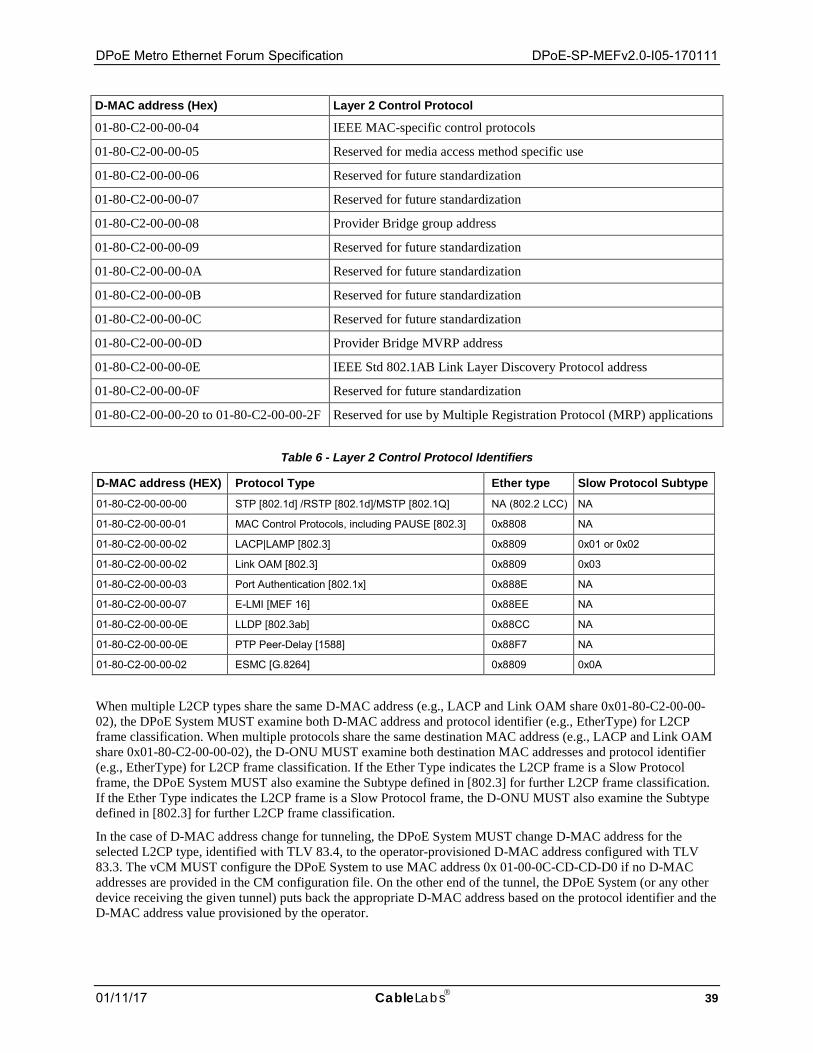
DPoE Metro Ethernet Forum Specification DPoE-SP-MEFv2.0-I05-170111
01/11/17 CableLabs 39
D-MAC address (Hex) Layer 2 Control Protocol
01-80-C2-00-00-04 IEEE MAC-specific control protocols
01-80-C2-00-00-05 Reserved for media access method specific use
01-80-C2-00-00-06 Reserved for future standardization
01-80-C2-00-00-07 Reserved for future standardization
01-80-C2-00-00-08 Provider Bridge group address
01-80-C2-00-00-09 Reserved for future standardization
01-80-C2-00-00-0A Reserved for future standardization
01-80-C2-00-00-0B Reserved for future standardization
01-80-C2-00-00-0C Reserved for future standardization
01-80-C2-00-00-0D Provider Bridge MVRP address
01-80-C2-00-00-0E IEEE Std 802.1AB Link Layer Discovery Protocol address
01-80-C2-00-00-0F Reserved for future standardization
01-80-C2-00-00-20 to 01-80-C2-00-00-2F Reserved for use by Multiple Registration Protocol (MRP) applications
Table 6 - Layer 2 Control Protocol Identifiers
D-MAC address (HEX) Protocol Type Ether type Slow Protocol Subtype 01-80-C2-00-00-00 STP [802.1d] /RSTP [802.1d]/MSTP [802.1Q] NA (802.2 LCC) NA
01-80-C2-00-00-01 MAC Control Protocols, including PAUSE [802.3] 0x8808 NA
01-80-C2-00-00-02 LACP|LAMP [802.3] 0x8809 0x01 or 0x02
01-80-C2-00-00-02 Link OAM [802.3] 0x8809 0x03
01-80-C2-00-00-03 Port Authentication [802.1x] 0x888E NA
01-80-C2-00-00-07 E-LMI [MEF 16] 0x88EE NA
01-80-C2-00-00-0E LLDP [802.3ab] 0x88CC NA
01-80-C2-00-00-0E PTP Peer-Delay [1588] 0x88F7 NA
01-80-C2-00-00-02 ESMC [G.8264] 0x8809 0x0A
When multiple L2CP types share the same D-MAC address (e.g., LACP and Link OAM share 0x01-80-C2-00-00-02), the DPoE System MUST examine both D-MAC address and protocol identifier (e.g., EtherType) for L2CP frame classification. When multiple protocols share the same destination MAC address (e.g., LACP and Link OAM share 0x01-80-C2-00-00-02), the D-ONU MUST examine both destination MAC addresses and protocol identifier (e.g., EtherType) for L2CP frame classification. If the Ether Type indicates the L2CP frame is a Slow Protocol frame, the DPoE System MUST also examine the Subtype defined in [802.3] for further L2CP frame classification. If the Ether Type indicates the L2CP frame is a Slow Protocol frame, the D-ONU MUST also examine the Subtype defined in [802.3] for further L2CP frame classification.
In the case of D-MAC address change for tunneling, the DPoE System MUST change D-MAC address for the selected L2CP type, identified with TLV 83.4, to the operator-provisioned D-MAC address configured with TLV 83.3. The vCM MUST configure the DPoE System to use MAC address 0x 01-00-0C-CD-CD-D0 if no D-MAC addresses are provided in the CM configuration file. On the other end of the tunnel, the DPoE System (or any other device receiving the given tunnel) puts back the appropriate D-MAC address based on the protocol identifier and the D-MAC address value provisioned by the operator.
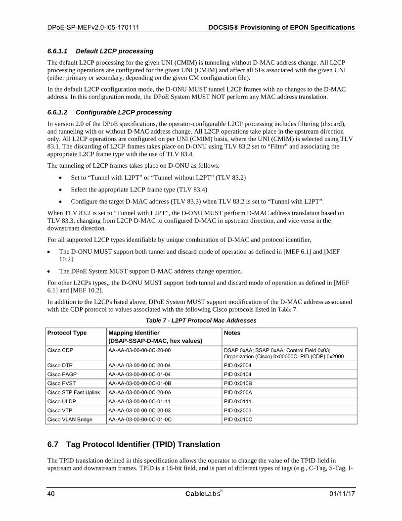
DPoE-SP-MEFv2.0-I05-170111 DOCSIS® Provisioning of EPON Specifications
40 CableLabs 01/11/17
6.6.1.1 Default L2CP processing The default L2CP processing for the given UNI (CMIM) is tunneling without D-MAC address change. All L2CP processing operations are configured for the given UNI (CMIM) and affect all SFs associated with the given UNI (either primary or secondary, depending on the given CM configuration file).
In the default L2CP configuration mode, the D-ONU MUST tunnel L2CP frames with no changes to the D-MAC address. In this configuration mode, the DPoE System MUST NOT perform any MAC address translation.
6.6.1.2 Configurable L2CP processing In version 2.0 of the DPoE specifications, the operator-configurable L2CP processing includes filtering (discard), and tunneling with or without D-MAC address change. All L2CP operations take place in the upstream direction only. All L2CP operations are configured on per UNI (CMIM) basis, where the UNI (CMIM) is selected using TLV 83.1. The discarding of L2CP frames takes place on D-ONU using TLV 83.2 set to “Filter” and associating the appropriate L2CP frame type with the use of TLV 83.4.
The tunneling of L2CP frames takes place on D-ONU as follows:
• Set to “Tunnel with L2PT” or “Tunnel without L2PT” (TLV 83.2)
• Select the appropriate L2CP frame type (TLV 83.4)
• Configure the target D-MAC address (TLV 83.3) when TLV 83.2 is set to “Tunnel with L2PT”.
When TLV 83.2 is set to “Tunnel with L2PT”, the D-ONU MUST perform D-MAC address translation based on TLV 83.3, changing from L2CP D-MAC to configured D-MAC in upstream direction, and vice versa in the downstream direction.
For all supported L2CP types identifiable by unique combination of D-MAC and protocol identifier,
• The D-ONU MUST support both tunnel and discard mode of operation as defined in [MEF 6.1] and [MEF 10.2].
• The DPoE System MUST support D-MAC address change operation.
For other L2CPs types,, the D-ONU MUST support both tunnel and discard mode of operation as defined in [MEF 6.1] and [MEF 10.2].
In addition to the L2CPs listed above, DPoE System MUST support modification of the D-MAC address associated with the CDP protocol to values associated with the following Cisco protocols listed in Table 7.
Table 7 - L2PT Protocol Mac Addresses
Protocol Type Mapping Identifier (DSAP-SSAP-D-MAC, hex values)
Notes
Cisco CDP AA-AA-03-00-00-0C-20-00 DSAP 0xAA; SSAP 0xAA; Control Field 0x03; Organization (Cisco) 0x00000C; PID (CDP) 0x2000
Cisco DTP AA-AA-03-00-00-0C-20-04 PID 0x2004
Cisco PAGP AA-AA-03-00-00-0C-01-04 PID 0x0104
Cisco PVST AA-AA-03-00-00-0C-01-0B PID 0x010B
Cisco STP Fast Uplink AA-AA-03-00-00-0C-20-0A PID 0x200A
Cisco ULDP AA-AA-03-00-00-0C-01-11 PID 0x0111
Cisco VTP AA-AA-03-00-00-0C-20-03 PID 0x2003
Cisco VLAN Bridge AA-AA-03-00-00-0C-01-0C PID 0x010C
6.7 Tag Protocol Identifier (TPID) Translation
The TPID translation defined in this specification allows the operator to change the value of the TPID field in upstream and downstream frames. TPID is a 16-bit field, and is part of different types of tags (e.g., C-Tag, S-Tag, I-
DPoE Metro Ethernet Forum Specification DPoE-SP-MEFv2.0-I05-170111
01/11/17 CableLabs 41
Tag, B-Tag) that are available for use in the DPoE Network. Each tagging mechanism, including [802.1ad] and [802.1ah], defines a standard TPID value. For example a value of 0x8100 is a standard TPID value for [802.1Q] frames. For various reasons such as backward compatibility with legacy switches, operators require the capability to change the value of TPID before forwarding the frame in downstream and upstream direction.
The DPoE System MAY support TPID translation in the upstream direction. The DPoE System MAY support TPID translation in the downstream direction.
If the TPID translation functionality is supported:
• The DPoE System MUST support TPID translation for an SI working in either Encapsulation or Transport Mode.
• The vCM MUST allow an operator to configure downstream and upstream TPID translation on a per-SI level.
Section 6.11.3 provides details on TLVs used to provision TPID translation.
6.8 CoS Mapping
The CoS mapping as defined in this specification serves two purposes:
• Map customer CoS values to the Service Provider CoS values. The service provider may map the CoS value from an incoming tagged frame to a value on the Service provider added tag.
• Map the customer CoS values from one protocol to another. The Service provider may map the CoS values in the Access Network to the CoS values in the Core Network. (e.g., S-Tag PCP to MPLS Traffic Class).
CoS mapping can be provisioned to take place in D-ONU or the DPoE System. CoS Mapping must be supported for upstream traffic - the ingress traffic to the Provider Network. CoS mapping may be supported for downstream traffic – the egress traffic from the Provider Network. To apply CoS Mapping on D-ONU in the upstream direction, the existing upstream classifier TLV 22 and L2VPN encapsulation TLV 43.5 is used. The mapped customer CoS is defined as part of the TLV 22 upstream classifier rule, whereas the mapping Service Provider CoS value is defined in the L2VPN encapsulation TLV 43.5 as part of the service provider added tag.
The DPoE System MUST support CoS mapping in the upstream direction, through provisioning mechanism defined in [DPoE-IPNEv2.0]. This allows mapping of CoS value from one protocol to another, including the mapping from Customer CoS value to Service Provider CoS value, or from Access Network CoS value to Core Network CoS value. This also allows CoS Mapping in Transport Mode.
Through the combination of CoS Mapping on D-ONU and CoS Mapping on DPoE System, it is possible to map customer CoS value into a Service Provider CoS value in Encapsulation Mode on D-ONU, and then further map CoS value from one protocol to another in transport mode on DPoE System. The DPoE System MAY support CoS Mapping in the downstream direction, through provisioning mechanism defined in the [DPoE-IPNEv2.0]. This will allow mapping of CoS value from one protocol to another, including the mapping of Core Network CoS value to Access Network CoS value (e.g., MPLS Traffic Class to S-Tag PCP). This will also allow CoS Mapping in Transport mode.
6.9 QoS for Metro Ethernet Services
QoS for Metro Ethernet services as defined in this specification focuses on the DPoE Network between the reference points C0 and CS.
The framework of SF and ASF, as defined in [DPoE-MULPIv2.0], is used to define QoS for Metro Ethernet services. An SF (and ASF) provisioned to provide upstream QoS are separate and independent from an SF (and ASF) provisioned to provide downstream QoS. A DPoE Network should be provisioned with both upstream and downstream SFs to provide QoS for a Metro Ethernet service in both directions.
The concept of ASF is new in version 2.0 of the DPoE specifications and was introduced, primarily, to allow multiplexing of more than one Metro Ethernet services into a single LLID. In contrast, version 1.0 of the DPoE specifications does not support the concept of ASF and does not allow the multiplexing of multiple Metro Ethernet services into a single LLID. By design, version 2.0 of DPoE specifications is backward compatible with version 1.0
DPoE-SP-MEFv2.0-I05-170111 DOCSIS® Provisioning of EPON Specifications
42 CableLabs 01/11/17
of DPoE specifications, which essentially means that the operators can use an SF or both SF and ASF to define QoS for Metro Ethernet services in DPoEv2.0 Network.
Since an SF can be standalone or aggregated into an ASF, this document defines the following terminology to identify one from the other.
• SF (Standalone): An SF not associated with an ASF.
• SF (Aggregated): An SF associated with an ASF.
An ASF is a grouping of one or more SFs, where an SF can be associated with either zero or one ASF.
The provisioning model in this specification provides flexibility for an operator to combine any one or more SFs for Metro Ethernet services into an ASF. Additionally, this specification does not impose any restriction or provide any guidance on methodology an operator should use to decide SF and Metro Ethernet service aggregation criteria. For example, the DPoE Network allows multiplexing of multiple and different type of Metro Ethernet services such as EPL, EVPL, EP-LAN, EVP-LAN, EP-Tree, and EVP-Tree with different QoS requirements into an ASF.
DPoEv1.0 supports DOCSIS QoS Parameters (DQP) to define QoS attributes of an SF. This specification defines an additional method, Metro Ethernet Service Profile, as defined in Section 6.9.1, to define the QoS attributes. Since version 2.0 of DPoE specifications is backward compatible with version 1.0 of DPoE specifications, it allows the use of either DQP or MESP to define QoS attributes for Metro Ethernet services.
• A vCM MUST allow the use of either MESP or DQP to define QoS attributes for an SF (Standalone).
• A vCM MUST allow the use of either MESP or DQP to define QoS attributes for an SF (Aggregated).
• A vCM MUST allow the use of MESP to define QoS attributes for an ASF.
Metro Ethernet Service Profile (MESP) 6.9.1The MESP can be used to provision QoS attributes for Metro Ethernet services such as EPL, EVPL, EP-LAN, EVP-LAN, EP-Tree and EVP-Tree. As detailed in the [DPoE-MULPIv2.0], the MESP can be used to define QoS attributes for an SF or ASF.
[DPoE-MULPIv2.0] specification allows a D-ONU and DPoE System to support multiple ASFs and SFs, where each can be associated with the same or different MESP. The scope of the QoS, provisioned using MESP is limited to the DPoE Network between the reference points C0 and CS. The QoS for transmission on D and MN interface is defined in the [DPoE-IPNEv2.0].
The MESP consists of various attributes characterizing QoS. The MESP is defined by the following set of attributes:
Bandwidth Profile (MESP-BP): The Bandwidth Profile is defined using:
• CIR, CBS, EIR, and EBS,
• CF, and
• Color Mode (CM). The Color Mode includes Color Identification Field configurations. With Color Identification Field(s) configured, the MESP-BP is implicitly configured in “color-aware” mode. Without Color Identification Field configured, the MESP-BP is implicitly configured in “color-blind” mode
For the definition of Bandwidth Profile and D-ONU and DPoE System requirements related to Bandwidth Profile, please see Section 6.9.1.1. The Coupling Flag (CF) is not supported in this version of the specification.
The Color Identification field in the Color Mode is used to identify color (e.g., green, yellow, and red) of the ingress frames. For the definition of these attributes and the D-ONU and DPoE System requirements related to color identification, please see Section 6.9.1.3.
Color Marking (MESP-CR): This Color Marking is used to mark color (e.g., green, yellow and red) in the frames after the agreed upon (between customer and service provider) Bandwidth Profile has been applied to the incoming frames. For the definition of these attributes and the D-ONU and DPoE System requirements related to Color Marking, please see Section 6.9.1.3.

DPoE Metro Ethernet Forum Specification DPoE-SP-MEFv2.0-I05-170111
01/11/17 CableLabs 43
6.9.1.1 Bandwidth Profile Definition Table 8 provides a definition of parameters included in the Bandwidth Profile. The detailed definition of Bandwidth Profile can be found in [MEF 10.2]. The Bandwidth Profile configuration rules and limitations are defined in [MEF 10.2], 7.11.1, Standard Bandwidth Profile Parameters and Algorithm.
Table 8 - Definition of MEF Bandwidth Profile
Name Description Units/Values CIR Defines the average rate of Service Frames up to which the network delivers these Frames
and meets the performance objectives. Kbits/sec
CBS Defines the maximum limit available for a burst of Service Frames sent at the UNI speed, to remain CIR-conformant.
Kbytes
EIR Defines the average rate of Service Frames up to which the network may deliver these Frames but without any performance objectives.
Kbits/sec
EBS Defines the maximum limit available for a burst of Service Frames sent at the UNI speed, to remain EIR-conformant.
Kbytes
CF The Coupling Flag allows the choice between two modes of operation of the rate enforcement algorithm. The Coupling Flag is not supported in this version of the specification.
Y or N
Color Mode (CM)
This parameter indicates whether the color-aware or color-blind property is employed by the Bandwidth Profile. This parameter is implicitly configured through the configuration of Color Identification Field. With Color Identification Field(s) configured, Bandwidth Profile is in “color-aware” mode; Without Color Identification Field configured, Bandwidth Profile is in “color-blind” mode.
Implicitly configured through Color Identification field configuration
As part of the QoS enforcement, DPoE Network performs a number of functions, which are defined as follows:
Green Color Marking: refers to the action of green color marking of frames based on execution of Bandwidth Profile algorithm as defined in Figure 13 in [MEF 10.2].
Yellow Color Marking: refers to the action of yellow color marking of frames based on execution of Bandwidth Profile algorithm as defined in Figure 13 in [MEF 10.2].
Red Color Marking (or Frame Drop): refers to the action of dropping of frames based on execution of Bandwidth Profile algorithm as defined in Figure 13 in [MEF 10.2].
Simple Drop: refers to the action of dropping frames when the assigned queue is full without regard to the color in the frame. A device performing Simple Drop function does so without regard to Bandwidth Profile parameters such as CIR and EIR.
Smart Color Drop: refers to the action of dropping frames when the assigned queue is full with consideration to the color in the frames. A device performing Smart Color Drop as a result of queue overflow function does so without regard to Bandwidth Profile parameters such as CIR, and EIR.
6.9.1.2 Color Identification Definition The color of a customer frame (green, yellow, and red) is identified using various fields in the frame. This field is agreed upon between the service provider and the customer. The colors are identified as defined by [MEF 10.2], section 7.11.1. (For details on Two-Rate Three color marking, refer to [RFC 4115]).
If the service is configured in the "Color Aware" mode (Color Mode for a service is assumed enabled if any of the color identification TLVs are provisioned), the D-ONU MUST take into consideration the color marked in the customer frame while determining the Bandwidth Profile compliance. If the value of "Color Aware" is set to "NO", the D-ONU MUST ignore the color marked on the customer frame while determining the Bandwidth Profile compliance. The details on how to determine Bandwidth Profile compliance can be found in section 7.11.1, Standard Bandwidth Profile Parameters and Algorithm, in [MEF 10.2]. When the color aware mode is enabled, the D-ONU MUST identify the color in the ingress frames using one of the following fields.
• DSCP/ToS IPv4
• DSCP/ToS IPv6
DPoE-SP-MEFv2.0-I05-170111 DOCSIS® Provisioning of EPON Specifications
44 CableLabs 01/11/17
• IPv6 Flow Label
• C-CFI
• C-PCP
• S-PCP
• I-PCP
• B-PCP
• S-DEI
• I-DEI
• B-DEI
The [DPoE-MULPIv2.0] specification provides the necessary TLVs to provision the D-ONU to identify color in the ingress frames.
If the CM configuration file includes more than one attribute specified above, the vCM MUST use the first attribute, by order of occurrence in the parent TLV containing the MESP fields, for color identification and ignore the rest.
6.9.1.3 Color Marking Definition After service frames are policed, the D-ONU MUST mark the color (Green, Yellow, and Red) in the egress frame using one of the following fields.
• S-PCP
• I-PCP
• B-PCP
• S-DEI
• I-DEI
• B-DEI
If the CM configuration file includes more than one attribute specified above, the vCM MUST use the first attribute, by order of occurrence in the parent TLV containing the MESP fields, for color marking and ignore the rest.
NOTE: Since the CoS mapping and the Color marking use the same fields, it is the operator's responsibility to ensure that the field that is used for CoS mapping (e.g., PCP of S-Tag) is not used for color marking in the same MESP instance.
DOCSIS QoS Parameters (DQP) 6.9.2
As originally specified in [DPoE-MEFv1.0], the following parameters can also be used to provision the QoS for Metro Ethernet services.
• Minimum Reserved Traffic Rate (TLV 24/25.10)
• Maximum Sustained Traffic Rate (TLV 24/25.8)
• Maximum Traffic Burst (TLV 24/25.9)
• Nominal Polling Interval (TLV 24.17)
DPoE Systems supports RTPS scheduling for all MEF upstream service flows.
In the case where DOCSIS QoS parameters and the MESP are used to define QoS for an SF, the vCM MUST use to MESP.
DPoE Metro Ethernet Forum Specification DPoE-SP-MEFv2.0-I05-170111
01/11/17 CableLabs 45
Upstream QoS Enforcement Requirements 6.9.3
Upstream QoS for a Metro Ethernet service is defined using one of the following two methods:
1. SF (Standalone): Metro Ethernet service is mapped to an SF and the SF is subsequently mapped to an LLID.
2. SF (Aggregated) and ASF: Metro Ethernet service is mapped to an SF, the SF is subsequently mapped to an ASF and the ASF is finally mapped to an LLID. The ASF allows aggregation of one or more SF.
For the case where upstream QoS is defined using an SF (Standalone), and the SF (Standalone) is defined using MESP, the DPoE System schedules the upstream bandwidth using the MESP Parameters – CIR, CBS, EIR, and EBS.
For the case where upstream QoS is defined using an SF (Standalone), and the SF (Standalone) is defined using DQP, the DPoE System schedules the upstream bandwidth using the DQP Parameters.
For the case where upstream QoS is defined using an SF (Aggregated) and ASF, the DPoE System schedules the upstream bandwidth using the MESP Parameters – CIR, CBS, EIR, and EBS – associated with the ASF.
A D-ONU performs QoS functions as described below.
For the case where upstream QoS is defined using an SF (Standalone), and SF QoS attributes are defined using DQP, a D-ONU supports the following functions at the SF level.
• A D-ONU MUST support the Simple Drop functionality.
For the case where upstream QoS is defined using an SF (Standalone), and SF QoS attributes are defined using MESP, a D-ONU supports the following functions at the SF level.
• A D-ONU MUST support the Simple Drop functionality.
• A D-ONU MAY support the Smart Color Drop functionality.
• A D-ONU MAY support the Color Aware functionality.
• A D-ONU MAY perform Green Color Marking.
• A D-ONU MAY perform Yellow Color Marking.
• A D-ONU MAY perform Red Color Marking
For the case where upstream QoS is defined using a combination of SF (Aggregated) and ASF, and SF QoS attributes are defined using DQP, a D-ONU supports the following functions at the SF level.
• A D-ONU MAY support the Simple Drop functionality.
For the case where upstream QoS is defined using a combination of SF (Aggregated) and ASF, and SF QoS attributes are defined using MESP, a D-ONU supports the following functions at the SF level.
• A D-ONU MAY support the Simple Drop functionality.
• A D-ONU MAY support the Smart Color Drop functionality.
• A D-ONU MAY support the Color Aware functionality.
• A D-ONU MAY perform Green Color Marking.
• A D-ONU MAY perform Yellow Color Marking.
• A D-ONU MAY perform Red Color Marking
For the case where upstream QoS is defined using a combination of SF (Aggregated) and ASF, and ASF QoS attributes are defined using MESP, a D-ONU supports the following functions at the ASF level.
• A D-ONU MUST support the Simple Drop functionality.
• A D-ONU MAY support the Smart Color Drop functionality.
DPoE-SP-MEFv2.0-I05-170111 DOCSIS® Provisioning of EPON Specifications
46 CableLabs 01/11/17
• A D-ONU MUST NOT support the Color Aware functionality.
• A D-ONU MUST NOT perform Green Color Marking.
• A D-ONU MUST NOT perform Yellow Color Marking.
• A D-ONU MUST NOT perform Red Color Marking.
Additionally, D-ONU MUST advertise whether it supports Color Aware mode. D-ONU MUST advertise this to the DPoE System using eOAM messages defined in [DPoE-OAMv2.0]. The vCM MUST reject the configuration file containing color-marking TLVs, if the D-ONU associated with the vCM does not support color-marking functionality. The vCM MUST reject the configuration file containing color-identification TLVs, if the D-ONU associated with the vCM does not support color-identification functionality.
Downstream QoS Enforcement Requirements 6.9.4
Downstream QoS for a Metro Ethernet service is defined using one of the following two methods:
3. SF (Standalone): Metro Ethernet service is mapped to an SF and the SF is subsequently mapped to an LLID
4. SF (Aggregated) and ASF: Metro Ethernet service is mapped to an SF, the SF is subsequently mapped to an ASF and the ASF is finally mapped to an LLID
For the case where downstream QoS is defined using an SF (Standalone), and the SF QoS attributes are defined using DQP, a DPoE System supports the following functions at the SF level.
• A DPoE System MUST support the Simple Drop functionality.
For the case where downstream QoS is defined using an SF (Standalone), and the SF QoS attributes are defined using MESP, a DPoE System supports the following functions at the SF level.
• A DPoE System MUST support the Smart Color Drop functionality.
• A DPoE System MUST support the Color Aware functionality.
• A DPoE System MUST perform Green Color Marking.
• A DPoE System MUST perform Yellow Color Marking.
• A DPoE System MUST perform Red Color Marking
For the case where downstream QoS is defined using combination of SF (Aggregated) and ASF, and the SF QoS attributes are defined using DQP, a DPoE System supports the following functions at the SF level.
• A DPoE System MUST support the Simple Drop functionality.
For the case where downstream QoS is defined using a combination of SF (Aggregated) and ASF, and the SF QoS attributes are defined using MESP, a DPoE System supports the following functions at the SF level.
• A DPoE System MUST support the Simple Drop functionality.
• A DPoE System MUST support the Smart Color Drop functionality.
• A DPoE System MUST support the Color Aware functionality.
• A DPoE System MUST perform Green Color Marking.
• A DPoE System MUST perform Yellow Color Marking.
• A DPoE System MUST perform Red Color Marking
For the case where downstream QoS is defined using a combination of SF (Aggregated) and ASF, and the ASF QoS attributes are defined using MESP, a DPoE System supports the following functions at the ASF level.
• A DPoE System MUST support the Simple Drop functionality.
• A DPoE System MUST support the Smart Color Drop functionality.
DPoE Metro Ethernet Forum Specification DPoE-SP-MEFv2.0-I05-170111
01/11/17 CableLabs 47
• A DPoE System MUST NOT support the Color Aware functionality.
• A DPoE System MUST NOT perform Green Color Marking.
• A DPoE System MUST NOT perform Yellow Color Marking.
• A DPoE System MUST NOT perform Red Color Marking
6.10 Ethernet Service OAM (S-OAM)13
S-OAM requirements are out of scope of Version 2.0 DPoE specifications.
6.11 Configuration and Management14
Annex A defines new TLVs to extend [L2VPN] provisioning to support the:
• Configuration of a Metro Ethernet service instance in either Transport or Encapsulation Mode. The TLV 43.5.13 is used for this configuration.
• Configuration that allows addition and deletion of S-TPID at the D-ONU in the PB Encapsulation Mode.
• Configuration that allows addition and deletion of [802.1ah] encapsulation at the D-ONU in the Encapsulation Mode. This includes the capability to individually configure I-TCI (TLV 43.5.2.6.1), I-SID (TLV 43.5.2.6.8), I-TPID (TLV 43.5.2.6.4), I-DEI (TLV 43.5.2.6.6), I-UCA (TLV 43.5.2.6.7), I-PCP (TLV 43.5.2.6.5), B-TCI (TLV 43.5.2.6.3), B-VID (TLV 43.5.2.6.12), B-DEI (TLV 43.5.2.6.11), B-PCP (TLV 43.5.2.6.10), B-DA (TLV 43.5.2.6.2), and B-TPID (TLV 43.5.2.6.9).
• Configuration that allows TPID translation by the DPoE System in the upstream direction for both Encapsulation and Transport Mode. The TPID Translation in upstream direction is configured using TLVs 43.5.14.
• Configuration that allows TPID translation by the DPoE System in the downstream direction for both Encapsulation Mode and Transport Mode. The TPID Translation in upstream direction is configured using TLVs 43.5.14.
• Configuration for L2CP frame processing for the Tunneling Mode. The L2CP frame processing is configured using TLVs 83.
• Configuration of VPLS and VPWS. Annex A defines a number of TLV to configure VPLS and VPWS related information.
TLVs used to configure Classifiers, MESP and ASF are defined in [DPoE-MULPIv2.0]. The vCM uses these TLVs to configure the D-ONU using eOAM defined in [DPoE-OAMv2.0].
Procedures for configuring B-SA, used in [802.1ah] encapsulation, are defined in [DPoE-IPNEv2.0].
Transport and Encapsulation Mode Configuration Requirements 6.11.1
The vCM MUST support TLV 43.5.13 to allow configuration of L2VPN Mode. The TLV used to configure Transport and Encapsulation Mode is defined in Annex A.1.
The vCM MUST use the L2VPN Mode TLV (43.5.13) in the CM configuration file to configure the D-ONU with L2VPN Mode. The D-ONU MUST use the vCM provided L2VPN Mode configuration. If the TLV 43.5.13 is not present in the CM configuration file, the vCM MUST configure the D-ONU with Encapsulation Mode, which is the default mode.
A vCM MUST support configuration of the PB transport mode on the D-ONU. A vCM MUST support configuration of the PBB transport mode on the D-ONU. 13 Revised per MEFv2.0-N-16.0237-1 on 6/2/16 by JB. 14 Revised per MEFv2.0-N-15.0227-1 on 2/5/16 by JB. Revised per MEFv2.0-N-16.0243-3 on 9/15/16 by JB.
DPoE-SP-MEFv2.0-I05-170111 DOCSIS® Provisioning of EPON Specifications
48 CableLabs 01/11/17
[802.1ad] Tagging Configuration Requirements15 6.11.2
A vCM MUST support configuration of the PB encapsulation mode on the associated D-ONU. The TLVs used to configure [802.1d] tagging are defined in Annex A.2. The vCM is provisioned with specific combination of [802.1ad] fields, which it then uses to configure the D-ONU via eOAM as described in [DPoE-OAMv2.0].
Current [L2VPN] TLV 43.5.2.3 is used to add at least one [802.1ad] tag: the outermost S-VLAN tag and/or the inner C-VLAN tag in the following supported combinations:
• inner C-VLAN tag only, when the respective portion of TLV 43.5.2.3 is not set to NULL, i.e., TLV 43.5.2.3 is set to “SS SS CC CC”, where CC CC represents a non-zero value expressed in hex notation;
• outer S-VLAN tag only, when the respective portion of TLV 43.5.2.3 is not set to NULL, i.e., TLV 43.5.2.3 is set to “SS SS CC CC”, where SS SS represents a non-zero value expressed in hex notation;
• inner C-VLAN and outer S-VLAN tags, when the respective portions of TLV 43.5.2.3 are not set to NULL, i.e., TLV 43.5.2.3 is set to “SS SS CC CC”, where SS SS and CC CC represent non-zero values expressed in hex notation.
The TLV 43.5.2.3 can be used to provision the following fields in the encapsulation VLAN tag(s): C-VID, C-PCP, and C-CFI for C-VLAN tag, and S-VID, S-PCP, and S-DFI for S-VLAN tag.
The vCM MUST support TLV 43.5.2.3 to allow configuration of [802.1ad] tagging.
If the CM configuration file contains both TLV 43.5.2.2 and TLV 43.5.2.3 for the same TLV 43, the DPoE System MUST use the configuration defined in TLV 43.5.2.3 and ignore the configuration defined in TLV 43.5.2.2.
The outermost S-VLAN tag uses the default TPID value of 0x88a8, and the inner C-VLAN tag uses the default TPID value of 0x8100. While TLV 43.5.2.3 can be used to configure most of the [802.1ad] fields, it does not provide a way to configure TPID. For that reason this specification defines a new TLV (TLV 43.5.2.8) to support the configuration of S-TPID.
The vCM MUST support TLV 43.5.2.8 to allow configuration of S-TPID for [802.1ad] tagging.
The vCM MUST use the S-TPID TLV (43.5.2.8) value in the CM configuration file to configure the D-ONU with S-TPID added as part of PB encapsulation. The D-ONU MUST use the S-TPID configuration, as provided by the vCM, to set the value of S-TPID field added as part of PB encapsulation. The vCM MUST configure the D-ONU with S-TPID field to 0x88a8 (TPID for [802.1ad]) if no S-TPID is provided in the configuration file.
The vCM MUST use the S-PCP value from the 802.1ad TLV 43.5.2.3 in the CM configuration file to configure the D-ONU with S-PCP added as part of PB encapsulation. The D-ONU MUST use the S-PCP configuration, as provided by the vCM, to set the value of S-PCP field added as part of PB encapsulation.
The vCM MUST use the S-DEI value from the 802.1ad TLV 43.5.2.3 in the CM configuration file to configure the D-ONU with S-DEI added as part of PB encapsulation. The D-ONU MUST use the S-DEI configuration, as provided by the vCM, to set the value of S-DEI field added as part of PB encapsulation.
The vCM MUST use the S-VID value from the 802.1ad TLV 43.5.2.3 in the CM configuration file to configure the D-ONU with S-VID added as part of PB encapsulation. The D-ONU MUST use the S-VID configuration, as provided by the vCM, to set the value of S-VID field added as part of PB encapsulation.
[802.1ah] Encapsulation Configuration Requirements 6.11.3A vCM MUST support configuration of the [802.1ah] encapsulation mode on the associated D-ONU. The TLVs used to configure [802.1ah] encapsulation are defined in Annex A.3.
The vCM MUST use the I-TCI TLV (43.5.2.6.1) value in the CM configuration file to configure the D-ONU with I-TCI to be used as part of [802.1ah] encapsulation. The D-ONU MUST use the vCM provided I-TCI configuration to set the value of I-TCI field added as part of [802.1ah] encapsulation.
15 Revised per MEFv2.0-N-14.0146-1 on 7/14/14 by JB.
DPoE Metro Ethernet Forum Specification DPoE-SP-MEFv2.0-I05-170111
01/11/17 CableLabs 49
The vCM MUST use the B-DA TLV (43.5.2.6.2) in the CM configuration file to configure the D-ONU with B-DA to be used as part of [802.1ah] encapsulation. The D-ONU MUST use the vCM provided B-DA to set the value of B-DA field added as part of [802.1ah] encapsulation. The B-DA is the MAC address of the destination BEB and is configured on the D-ONU by the vCM.
The vCM MUST use the B-TCI TLV (43.5.2.6.3) value in the CM configuration file to configure the D-ONU with B-TCI to be used as part of [802.1ah] encapsulation. The D-ONU MUST use the vCM provided B-TCI configuration to set the value of B-TCI field added as part of [802.1ah] encapsulation.
The vCM MUST use the I-TPID TLV (43.5.2.6.4) value in the CM configuration file to configure the D-ONU with I-TPID to be used as part of [802.1ah] encapsulation. The vCM MUST use the [802.1ah] prescribed I-TPID value 0x88e7, if no I-TPID is provided in the CM configuration file, to configure the D-ONU with I-TPID to be used as part of [802.1ah] encapsulation. The D-ONU MUST use the vCM provided I-TPID configuration to set the value of I-TPID field added as part of [802.1ah] encapsulation.
The vCM MUST use the I-PCP TLV (43.5.2.6.5) value in the CM configuration file to configure the D-ONU with I-PCP to be used as part of [802.1ah] encapsulation. The vCM MUST use the I-PCP value of 0 (0b000), if no I-PCP is provided in the CM configuration file, to configure the D-ONU with I-PCP to be used as part of [802.1ah] encapsulation. The D-ONU MUST use the vCM provided I-PCP configuration to set the value of I-PCP field added as part of [802.1ah] encapsulation. If the [L2VPN] encoding includes both I-TCI and I-PCP, the vCM MUST use the I-PCP TLV (43.5.2.6.5) to configure I-PCP on the D-ONU.
The vCM MUST use the I-DEI TLV (43.5.2.6.6) value in the CM configuration file to configure the D-ONU with I-DEI to be used as part of [802.1ah] encapsulation. The vCM MUST use the I-DEI value of 0 (0b0), if no I-DEI is provided in the CM configuration file, to configure the D-ONU with I-DEI to be used as part of [802.1ah] encapsulation. The D-ONU MUST use the vCM provided I-DEI configuration to set the value of I-DEI field added as part of [802.1ah] encapsulation. If the [L2VPN] encoding includes both I-TCI and I-DEI, the vCM MUST use the I-DEI TLV (43.5.2.6.6) to configure I-DEI on the D-ONU.
The vCM MUST use the I-UCA TLV (43.5.2.6.7) value in the CM configuration file to configure the D-ONU with I-UCA to be used as part of [802.1ah] encapsulation. The vCM MUST use the I-UCA value of 0 (0b0), if no I-UCA is provided in the CM configuration file, to configure the D-ONU with I-UCA to be used as part of [802.1ah] encapsulation. The D-ONU MUST use the vCM provided I-UCA configuration to set the value of I-UCA field added as part of [802.1ah] encapsulation.
The vCM MUST use the I-SID TLV (43.5.2.6.8) value in the CM configuration file to configure the D-ONU with I-SID to be used as part of [802.1ah] encapsulation. The D-ONU MUST use the vCM provided I-SID configuration to set the value of I-SID field added as part of [802.1ah] encapsulation.
The vCM MUST use the B-TPID TLV (43.5.2.6.9) value in the CM configuration file to configure the D-ONU with B-TPID to be used as part of [802.1ah] encapsulation. The vCM MUST use the [802.1ah] prescribed B-TPID value 0x88a8, if no B-TPID is provided in the CM configuration file, to configure the D-ONU with B-TPID to be used as part of [802.1ah] encapsulation. The D-ONU MUST use the vCM provided B-TPID configuration to set the value of B-TPID field added as part of [802.1ah] encapsulation.
The vCM MUST use the B-PCP TLV (43.5.2.6.10) value in the CM configuration file to configure the D-ONU with B-PCP to be used as part of [802.1ah] encapsulation. The vCM MUST use the B-PCP value of 0 (0b000), if no B-PCP is provided in the CM configuration file, to configure the D-ONU with B-PCP to be used as part of [802.1ah] encapsulation. The D-ONU MUST use the vCM provided B-PCP configuration to set the value of B-PCP field added as part of [802.1ah] encapsulation. If the [L2VPN] encoding includes both B-TCI and B-PCP, the vCM MUST use the B-PCP TLV (43.5.2.6.10) to configure B-PCP on the D-ONU.
The vCM MUST use the B-DEI TLV (43.5.2.6.11) value in the CM configuration file to configure the D-ONU with B-DEI to be used as part of [802.1ah] encapsulation. The vCM MUST use the B-DEI value of 0 (0b0), if no B-DEI is provided in the CM configuration file, to configure the D-ONU with B-DEI to be used as part of [802.1ah] encapsulation. The D-ONU MUST use the vCM provided B-DEI configuration to set the value of B-DEI field added as part of [802.1ah] encapsulation. If the [L2VPN] encoding includes both B-TCI and B-DEI, the vCM MUST use the B-DEI TLV (43.5.2.6.11) to configure B-DEI on the D-ONU.
DPoE-SP-MEFv2.0-I05-170111 DOCSIS® Provisioning of EPON Specifications
50 CableLabs 01/11/17
The vCM MUST use the B-VID TLV (43.5.2.6.12) value in the CM configuration file to configure the D-ONU with B-VID to be used as part of [802.1ah] encapsulation. The D-ONU MUST use the vCM provided B-VID configuration to set the value of B-VID field added as part of [802.1ah] encapsulation.
An operator uses the [DPoE-IPNEv2.0] mechanisms to configure the B-SA field on the DPoE System. B-SA is the MAC address of the source BEB on the DPoE System and is assigned to MN interface. DPoE System MUST provision the ONU to add the proper value of the B-SA into ingressing frames. The provisioning process uses mechanisms defined in [DPoE-OAMv2.0].
TPID Translation Configuration Requirements 6.11.4
As stated in Section 6.7, it is optional for a DPoE System to support TPID Translation. As a result, a vCM, which is part of the DPoE System that does not support TPID Translation functionality, MUST reject configuration files containing any TPID translation TLVs.
Since the support for TPID Translation on DPoE System is optional, the requirements in this section are applicable to a DPoE System that support TPID translation.
The vCM MUST support configurations to translate the outermost TPID in upstream only, downstream only and both upstream and downstream direction. In the upstream direction, the DPoE System MUST replace the outermost TPID value in the PB or PBB frames with the value provisioned in TLV 43.5.14.1, only if this TLV is present in the configuration file. In the downstream direction, the DPoE System MUST replace the outmost TPID value in the PB or PBB frames with the value provisioned in TLV 43.5.14.2, only if this TLV is present in the configuration file. If a configuration file makes use of TLV 43.5.14.1 and TLV 43.5.14.2 for TPID translation for frames belonging to a Metro Ethernet service, then the other TPID translation TLVs, defined below, cannot be used for the same Metro Ethernet service. The vCM MUST reject the configuration file that includes TLV 43.5.14.1 and TLV 43.5.14.2 with any other TPID translation TLVs for the same Metro Ethernet service. With the introduction of TLVs for TPID translation, the use of TLV 43.5.14.1 and TLV 43.5.14.2 is discouraged in DPoEv2.0 specifications.
The vCM MUST support configurations to translate S-TPID in both upstream and downstream direction. In the upstream direction, the DPoE System MUST replace the S-TPID value in the PB frames with the value provisioned in TLV 43.5.14.3, only if this TLV is present in the configuration file. In the downstream direction, the DPoE System MUST replace the S-TPID value in the PB frames with the value provisioned in TLV 43.5.14.4, only if this TLV is present in the configuration file.
The vCM MUST support configurations to translate B-TPID in both upstream and downstream direction. In the upstream direction, the DPoE System MUST replace the B-TPID value in the PBB frames with the value provisioned in TLV 43.5.14.5, only if this TLV is present in the configuration file. In the downstream direction, the DPoE System MUST replace the B-TPID value in the PBB frames with the value provisioned in TLV 43.5.14.6, only if this TLV is present in the configuration file.
The vCM MUST support configurations to translate I-TPID only in both upstream and downstream direction. In the upstream direction, the DPoE System MUST replace the I-TPID value in the PBB frames with the value provisioned in TLV 43.5.14.7, only if this TLV is present in the configuration file. In the downstream direction, the DPoE System MUST replace the I-TPID value in the PBB frames with the value provisioned in TLV 43.5.14.8, only if this TLV is present in the configuration file.
The vCM MUST support the configuration to allow translation of both B-TPID and I-TPID in both upstream and downstream direction. In the upstream direction, the DPoE System MUST replace the I-TPID and B-TPID value in the PBB frames with the value provisioned in TLV 43.5.14.5 and TLV 43.5.14.7 respectively. In the downstream direction, the DPoE System MUST replace the I-TPID and B-TPID value in the PBB frames with the value provisioned in TLV 43.5.14.6 and TLV 43.5.14.8 respectively.
L2CP Configuration Requirements16 6.11.5
Section 6.6 provides L2CP requirements that are supported as part of Metro Ethernet service in the DPoE Network. This section provides L2CP configuration related requirements.
16 Revised per MEFv2.0-N-16.0243-3 on 9/15/16 by JB.
DPoE Metro Ethernet Forum Specification DPoE-SP-MEFv2.0-I05-170111
01/11/17 CableLabs 51
As described in Section 6.6, this specification supports three options for L2CP frame handling: 1) Filter (discard), 2) Tunnel with D-MAC address change, and 3) Tunnel without D-MAC address change. All L2CP configuration is performed on per UNI (CMIM) basis.
6.11.5.1 L2CP Configuration Requirements for the Discard Mode When TLV 83.2 is set to the value of 2 (“Filter”), L2CP frames associated with the given UNI (CMIM) and selected with TLV 83.4 are filtered (dropped). A D-ONU may also support discarding selected L2CP frames with the use of Upstream Drop Classifier (UDC) configuration.
6.11.5.2 L2CP Configuration Requirements for the Tunneling Mode This specification introduces a new TLV 83 to configure the Tunnel mode for L2CP frames in the following cases:
When the TLV 83.2 is set to 1 “Tunnel with L2PT", the D-MAC addresses in the L2CP frames associated with the given UNI (CMIM) and selected with the use of TLV 83.4 are changed to the value configured in TLV 83.3.
• In the upstream direction, the DPoE System MUST change the D-MAC address in the selected L2CP frames to the D-MAC address provisioned using TLV 83.3. In the upstream direction, the D-ONU MUST add any encapsulation and tagging configured as part of the Encapsulation Mode (if configured) to the L2CP frames.
• In the downstream direction, the DPoE System MUST restore the D-MAC address in the L2CP frames by referencing the Ether type/Subtype in the L2CP frames and Table 6. In the downstream direction, the D-ONU MUST remove any encapsulation and tagging configured as part of the Encapsulation Mode (if configured) from the L2CP frames.
When the TLV 83.21 is set to 2 "Tunnel without L2PT", the D-MAC address in the L2CP frames as configured in TLV 43.5.12.2 are not changed.
• In the upstream direction, the D-ONU MUST add any encapsulation and tagging configured as part of the Encapsulation Mode to the L2CP frames.
• In the downstream direction, the D-ONU MUST remove any encapsulation and tagging configured as part of the Encapsulation Mode from the L2CP frames. This is also the default mode of operation as described in Section 6.6.1.1.
When the TLV 83.2 is set to 3 “Filter”, the L2CP frames associated with the given UNI (CMIM) and selected with the use of TLV 43.5.15.2 are discarded.
• In the upstream direction, the D-ONU MUST discard any L2CP frames that match the L2CP type configured with the use of TLV 43.5.15.2.
• In the downstream direction, the DPoE System MUST discard any L2CP frames that match the L2CP type configured with the use of TLV 43.5.15.2.
MEF QoS Configuration Requirements 6.11.6
The MEF QoS configuration requirements can be found in [DPoE-MULPIv2.0].
6.12 Metro Ethernet Service Attributes
Annex B provides a summary of the following Metro Ethernet service attributes, provisioning and values. Additionally, wherever applicable, it describes how they are supported using the provisioning model used for the DPoE Network.
• MEF UNI EPL service attributes,
• MEF UNI EVPL service attributes,
• MEF UNI EP-LAN service attributes,
• MEF UNI EVP-LAN service attributes,
DPoE-SP-MEFv2.0-I05-170111 DOCSIS® Provisioning of EPON Specifications
52 CableLabs 01/11/17
• MEF UNI EP-Tree service attributes,
• MEF UNI EVP-Tree service attributes,
• MEF EVC service attributes, and
• EVC per UNI service attributes.
6.13 DOCSIS L2VPN TLVs
The vCM MUST support the following TLVs defined in [L2VPN]:
• Cable Modem Interface Mask (CMIM) Sub-type (43.5.4). This TLV is described in section B.3.4 of [L2VPN]. The TLV is used to map traffic of the MU or MI interface to a Metro Ethernet service instance.
• VPN Identifier (VPNID) (43.5.1). This TLV is described in section B.3.1 of [L2VPN]. The TLV is used to provision the [L2VPN] Identifier, which is also used as the EVC Identifier. As an example, the Service Provider might use "EVC-0001898-MEGAMART" to represent the 1898th EVC in the MEN, and the customer for the EVC is MegaMart. This specification currently requires compliance with L2VPN encoding location as specified in section 6.2 of [L2VPN].
DPoE Metro Ethernet Forum Specification DPoE-SP-MEFv2.0-I05-170111
01/11/17 CableLabs 53
7 MEF USAGE ACCOUNTING REQUIREMENTS (NORMATIVE) [MEF 7.1] incorporates the concept of a "Traffic Management Performance Data Set" from [Q.840.1]. [MEF 7.1] defines two sets of "Traffic Management Performance Data" one for the ingress to the MEN and one for egress from the MEN.
The DPoE System MUST maintain a Traffic Management Performance Data Set for each MEF SF. The D-ONU MUST maintain a Traffic Management Performance Data Set for each MEF Service Flow SF and UNI interface. 17 DPoE Systems MUST measure Traffic Management Performance Data Set frames and octets based on the enforcement of the MESP. The D-ONU MUST measure Traffic Management Performance Data Set frames and octets based on the enforcement of the MESP. 18 The D-ONU MUST count frames and octets in an associated ETH Ingress Traffic Management Data Set per [MEF 7.1] for all upstream MEF SFs. The DPoE System MUST count frames and octets in an associated ETH Egress Traffic Management Data Set for all downstream MEF SFs.
Per [DPoE-OSSIv2.0], management reporting via an external interface is performed solely on the DPoE System for both upstream and downstream SFs (this reporting includes additional information which allows for association of the Traffic Management Data Set with individual subscribers). Per [DPoE-OAMv2.0], upstream Traffic Management Data Set data is transferred from the D-ONU to the DPoE System for reporting.
[MEF 7.1] does not cover one additional set of counters necessary for monitoring DPoE Networks compliant with version 2.0 of DPoE specifications. The DPoE System MUST count all forwarded and discarded L2CP frames and octets for all downstream MEF SFs. The D-ONU MUST count all forwarded and discarded L2CP frames and octets for all upstream MEF SFs. Again, requirements for management reporting via an external interface for these counters are defined in [DPoE-OSSIv2.0] and requirements for reporting of these counters by the D-ONU to the D-OLT are defined in [DPoE-OAMv2.0].
17 A “MEF Service Flow” is defined as any of the following:
1. An Aggregate Service Flow with an MESP 2. A Service Flow with an associated MESP 3. A DPoE 1.0 Service Flow for MEF Services (i.e., a DPoE 1.0 RTP Service Flow)
18 This is consistent with the [MEF 7.1] statement that “the set of Ingress Traffic Management performance measurements [exist] on a per entity basis for each entity that enforces traffic management at the Ingress direction (CE to MEN).”
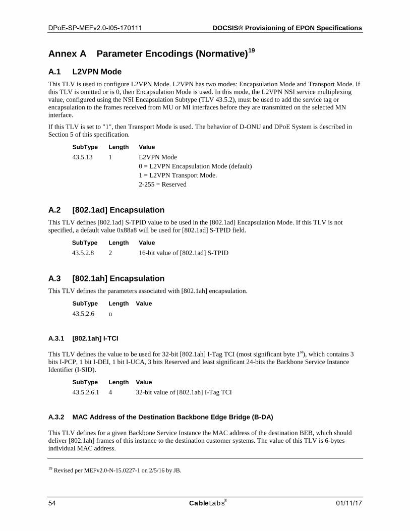
DPoE-SP-MEFv2.0-I05-170111 DOCSIS® Provisioning of EPON Specifications
54 CableLabs 01/11/17
Annex A Parameter Encodings (Normative)19
A.1 L2VPN Mode This TLV is used to configure L2VPN Mode. L2VPN has two modes: Encapsulation Mode and Transport Mode. If this TLV is omitted or is 0, then Encapsulation Mode is used. In this mode, the L2VPN NSI service multiplexing value, configured using the NSI Encapsulation Subtype (TLV 43.5.2), must be used to add the service tag or encapsulation to the frames received from MU or MI interfaces before they are transmitted on the selected MN interface.
If this TLV is set to "1", then Transport Mode is used. The behavior of D-ONU and DPoE System is described in Section 5 of this specification.
SubType Length Value 43.5.13 1 L2VPN Mode
0 = L2VPN Encapsulation Mode (default) 1 = L2VPN Transport Mode. 2-255 = Reserved
A.2 [802.1ad] Encapsulation This TLV defines [802.1ad] S-TPID value to be used in the [802.1ad] Encapsulation Mode. If this TLV is not specified, a default value 0x88a8 will be used for [802.1ad] S-TPID field.
SubType Length Value 43.5.2.8 2 16-bit value of [802.1ad] S-TPID
A.3 [802.1ah] Encapsulation This TLV defines the parameters associated with [802.1ah] encapsulation.
SubType Length Value 43.5.2.6 n
A.3.1 [802.1ah] I-TCI
This TLV defines the value to be used for 32-bit [802.1ah] I-Tag TCI (most significant byte 1st), which contains 3 bits I-PCP, 1 bit I-DEI, 1 bit I-UCA, 3 bits Reserved and least significant 24-bits the Backbone Service Instance Identifier (I-SID).
SubType Length Value 43.5.2.6.1 4 32-bit value of [802.1ah] I-Tag TCI
A.3.2 MAC Address of the Destination Backbone Edge Bridge (B-DA)
This TLV defines for a given Backbone Service Instance the MAC address of the destination BEB, which should deliver [802.1ah] frames of this instance to the destination customer systems. The value of this TLV is 6-bytes individual MAC address.
19 Revised per MEFv2.0-N-15.0227-1 on 2/5/16 by JB.
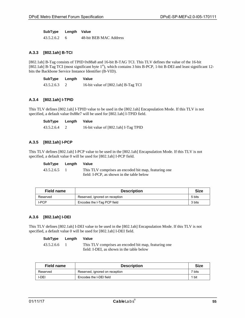
DPoE Metro Ethernet Forum Specification DPoE-SP-MEFv2.0-I05-170111
01/11/17 CableLabs 55
SubType Length Value 43.5.2.6.2 6 48-bit BEB MAC Address
A.3.3 [802.1ah] B-TCI
[802.1ah] B-Tag consists of TPID 0x88a8 and 16-bit B-TAG TCI. This TLV defines the value of the 16-bit [802.1ah] B-Tag TCI (most significant byte 1st), which contains 3 bits B-PCP, 1-bit B-DEI and least significant 12-bits the Backbone Service Instance Identifier (B-VID).
SubType Length Value 43.5.2.6.3 2 16-bit value of [802.1ah] B-Tag TCI
A.3.4 [802.1ah] I-TPID
This TLV defines [802.1ah] I-TPID value to be used in the [802.1ah] Encapsulation Mode. If this TLV is not specified, a default value 0x88e7 will be used for [802.1ah] I-TPID field.
SubType Length Value 43.5.2.6.4 2 16-bit value of [802.1ah] I-Tag TPID
A.3.5 [802.1ah] I-PCP
This TLV defines [802.1ah] I-PCP value to be used in the [802.1ah] Encapsulation Mode. If this TLV is not specified, a default value 0 will be used for [802.1ah] I-PCP field.
SubType Length Value 43.5.2.6.5 1 This TLV comprises an encoded bit map, featuring one
field: I-PCP, as shown in the table below
Field name Description Size
Reserved Reserved, ignored on reception 5 bits
I-PCP Encodes the I-Tag PCP field 3 bits
A.3.6 [802.1ah] I-DEI
This TLV defines [802.1ah] I-DEI value to be used in the [802.1ah] Encapsulation Mode. If this TLV is not specified, a default value 0 will be used for [802.1ah] I-DEI field.
SubType Length Value 43.5.2.6.6 1 This TLV comprises an encoded bit map, featuring one
field: I-DEI, as shown in the table below
Field name Description Size
Reserved Reserved, ignored on reception 7 bits
I-DEI Encodes the I-DEI field 1 bit
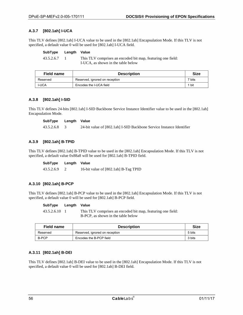
DPoE-SP-MEFv2.0-I05-170111 DOCSIS® Provisioning of EPON Specifications
56 CableLabs 01/11/17
A.3.7 [802.1ah] I-UCA
This TLV defines [802.1ah] I-UCA value to be used in the [802.1ah] Encapsulation Mode. If this TLV is not specified, a default value 0 will be used for [802.1ah] I-UCA field.
SubType Length Value 43.5.2.6.7 1 This TLV comprises an encoded bit map, featuring one field:
I-UCA, as shown in the table below
Field name Description Size Reserved Reserved, ignored on reception 7 bits
I-UCA Encodes the I-UCA field 1 bit
A.3.8 [802.1ah] I-SID
This TLV defines 24-bits [802.1ah] I-SID Backbone Service Instance Identifier value to be used in the [802.1ah] Encapsulation Mode.
SubType Length Value 43.5.2.6.8 3 24-bit value of [802.1ah] I-SID Backbone Service Instance Identifier
A.3.9 [802.1ah] B-TPID
This TLV defines [802.1ah] B-TPID value to be used in the [802.1ah] Encapsulation Mode. If this TLV is not specified, a default value 0x88a8 will be used for [802.1ah] B-TPID field.
SubType Length Value 43.5.2.6.9 2 16-bit value of [802.1ah] B-Tag TPID
A.3.10 [802.1ah] B-PCP
This TLV defines [802.1ah] B-PCP value to be used in the [802.1ah] Encapsulation Mode. If this TLV is not specified, a default value 0 will be used for [802.1ah] B-PCP field.
SubType Length Value 43.5.2.6.10 1 This TLV comprises an encoded bit map, featuring one field:
B-PCP, as shown in the table below
Field name Description Size Reserved Reserved, ignored on reception 5 bits
B-PCP Encodes the B-PCP field 3 bits
A.3.11 [802.1ah] B-DEI
This TLV defines [802.1ah] B-DEI value to be used in the [802.1ah] Encapsulation Mode. If this TLV is not specified, a default value 0 will be used for [802.1ah] B-DEI field.
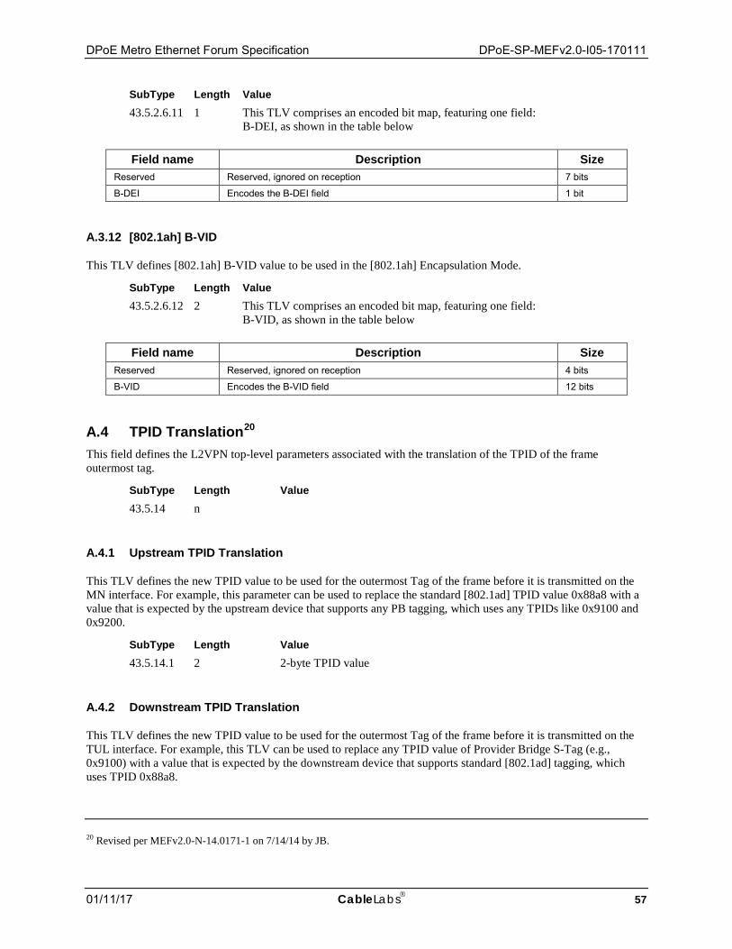
DPoE Metro Ethernet Forum Specification DPoE-SP-MEFv2.0-I05-170111
01/11/17 CableLabs 57
SubType Length Value 43.5.2.6.11 1 This TLV comprises an encoded bit map, featuring one field:
B-DEI, as shown in the table below
Field name Description Size Reserved Reserved, ignored on reception 7 bits
B-DEI Encodes the B-DEI field 1 bit
A.3.12 [802.1ah] B-VID
This TLV defines [802.1ah] B-VID value to be used in the [802.1ah] Encapsulation Mode.
SubType Length Value 43.5.2.6.12 2 This TLV comprises an encoded bit map, featuring one field:
B-VID, as shown in the table below
Field name Description Size Reserved Reserved, ignored on reception 4 bits
B-VID Encodes the B-VID field 12 bits
A.4 TPID Translation20 This field defines the L2VPN top-level parameters associated with the translation of the TPID of the frame outermost tag.
SubType Length Value 43.5.14 n
A.4.1 Upstream TPID Translation
This TLV defines the new TPID value to be used for the outermost Tag of the frame before it is transmitted on the MN interface. For example, this parameter can be used to replace the standard [802.1ad] TPID value 0x88a8 with a value that is expected by the upstream device that supports any PB tagging, which uses any TPIDs like 0x9100 and 0x9200.
SubType Length Value 43.5.14.1 2 2-byte TPID value
A.4.2 Downstream TPID Translation
This TLV defines the new TPID value to be used for the outermost Tag of the frame before it is transmitted on the TUL interface. For example, this TLV can be used to replace any TPID value of Provider Bridge S-Tag (e.g., 0x9100) with a value that is expected by the downstream device that supports standard [802.1ad] tagging, which uses TPID 0x88a8.
20 Revised per MEFv2.0-N-14.0171-1 on 7/14/14 by JB.

DPoE-SP-MEFv2.0-I05-170111 DOCSIS® Provisioning of EPON Specifications
58 CableLabs 01/11/17
SubType Length Value 43.5.14.2 2 2-byte TPID value
A.4.3 Upstream S-TPID Translation
This TLV defines the new TPID value to be used for the outermost S-Tag of the frame before it is transmitted on the MN interface. For example, this TLV can be used to replace the standard [802.1ad] TPID value 0x88a8 with a value that is expected by the upstream device that supports any PB tagging, which uses any TPIDs like 0x9100 and 0x9200.
SubType Length Value 43.5.14.3 2 2-byte TPID value
A.4.4 Downstream S-TPID Translation
This TLV defines the new TPID value to be used for the outermost S-Tag of the frame before it is transmitted on the TUL interface. For example, this TLV can be used to replace any TPID value of PB S-Tag (e.g., 0x9100) with a value that is expected by the downstream device that supports standard [802.1ad] tagging, which uses TPID 0x88a8.
SubType Length Value 43.5.14.4 2 2-byte TPID value
A.4.5 Upstream B-TPID Translation
This TLV defines the new TPID value to be used for the outermost B-Tag of the frame before it is transmitted on the MN interface. For example, this TLV can be used to replace the standard [802.1Q] TPID value 0x88a8 with a value that is expected by the upstream device that supports any PBB tagging.
SubType Length Value 43.5.14.5 2 2-byte TPID value
A.4.6 Downstream B-TPID Translation
This parameter defines the new TPID value to be used for the outermost B-Tag of the frame before it is transmitted on the TUL interface. For example, this parameter can be used to replace any TPID value of PBB B-Tag with a value that is expected by the downstream device that supports standard [802.1Q]tagging, which uses TPID 0x88a8.
SubType Length Value 43.5.14.6 2 2-byte TPID value
A.4.7 Upstream I-TPID Translation
This TLV defines the new TPID value to be used for the outermost I-Tag of the frame before it is transmitted on the MN interface. For example, this TLV can be used to replace the standard [802.1Q] TPID value 0x88e7 with a value that is expected by the upstream device that supports PBB tagging.
SubType Length Value 43.5.14.7 2 2-byte TPID value
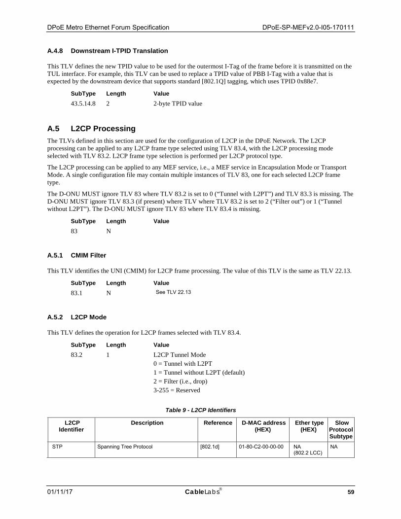
DPoE Metro Ethernet Forum Specification DPoE-SP-MEFv2.0-I05-170111
01/11/17 CableLabs 59
A.4.8 Downstream I-TPID Translation
This TLV defines the new TPID value to be used for the outermost I-Tag of the frame before it is transmitted on the TUL interface. For example, this TLV can be used to replace a TPID value of PBB I-Tag with a value that is expected by the downstream device that supports standard [802.1Q] tagging, which uses TPID 0x88e7.
SubType Length Value 43.5.14.8 2 2-byte TPID value
A.5 L2CP Processing The TLVs defined in this section are used for the configuration of L2CP in the DPoE Network. The L2CP processing can be applied to any L2CP frame type selected using TLV 83.4, with the L2CP processing mode selected with TLV 83.2. L2CP frame type selection is performed per L2CP protocol type.
The L2CP processing can be applied to any MEF service, i.e., a MEF service in Encapsulation Mode or Transport Mode. A single configuration file may contain multiple instances of TLV 83, one for each selected L2CP frame type.
The D-ONU MUST ignore TLV 83 where TLV 83.2 is set to 0 (“Tunnel with L2PT”) and TLV 83.3 is missing. The D-ONU MUST ignore TLV 83.3 (if present) where TLV where TLV 83.2 is set to 2 (“Filter out”) or 1 (“Tunnel without L2PT”). The D-ONU MUST ignore TLV 83 where TLV 83.4 is missing.
SubType Length Value 83 N
A.5.1 CMIM Filter
This TLV identifies the UNI (CMIM) for L2CP frame processing. The value of this TLV is the same as TLV 22.13.
SubType Length Value 83.1 N See TLV 22.13
A.5.2 L2CP Mode
This TLV defines the operation for L2CP frames selected with TLV 83.4.
SubType Length Value 83.2 1 L2CP Tunnel Mode
0 = Tunnel with L2PT 1 = Tunnel without L2PT (default) 2 = Filter (i.e., drop) 3-255 = Reserved
Table 9 - L2CP Identifiers
L2CP Identifier
Description Reference D-MAC address (HEX)
Ether type (HEX)
Slow Protocol Subtype
STP Spanning Tree Protocol [802.1d] 01-80-C2-00-00-00 NA (802.2 LCC)
NA
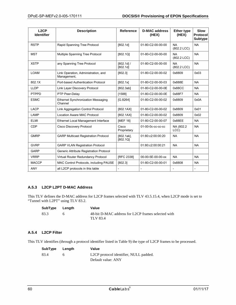
DPoE-SP-MEFv2.0-I05-170111 DOCSIS® Provisioning of EPON Specifications
60 CableLabs 01/11/17
L2CP Identifier
Description Reference D-MAC address (HEX)
Ether type (HEX)
Slow Protocol Subtype
RSTP Rapid Spanning Tree Protocol [802.1d] 01-80-C2-00-00-00 NA (802.2 LCC)
NA
MST Multiple Spanning Tree Protocol [802.1Q] 01-80-C2-00-00-00 NA (802.2 LCC)
NA
XSTP any Spanning Tree Protocol [802.1d] / [802.1d]
01-80-C2-00-00-00 NA (802.2 LCC)
NA
LOAM Link Operation, Administration, and Management,
[802.3] 01-80-C2-00-00-02 0x8809 0x03
802.1X Port-based Authentication Protocol [802.1x] 01-80-C2-00-00-03 0x888E NA
LLDP Link Layer Discovery Protocol [802.3ab] 01-80-C2-00-00-0E 0x88CC NA
PTPPD PTP Peer-Delay [1588] 01-80-C2-00-00-0E 0x88F7 NA
ESMC Ethernet Synchronization Messaging Channel
[G.8264] 01-80-C2-00-00-02 0x8809 0x0A
LACP Link Aggregation Control Protocol [802.1AX] 01-80-C2-00-00-02 0x8809 0x01
LAMP Location Aware MAC Protocol [802.1AX] 01-80-C2-00-00-02 0x8809 0x02
ELMI Ethernet Local Management Interface [MEF 16] 01-80-C2-00-00-07 0x88EE NA
CDP Cisco Discovery Protocol Cisco Proprietary
01-00-0c-cc-cc-cc NA (802.2 LCC)
NA
GMRP GARP Multicast Registration Protocol [802.1ak], [802.1Q]
01:80:c2:00:00:20 NA NA
GVRP GARP VLAN Registration Protocol 01:80:c2:00:00:21 NA NA
GARP Generic Attribute Registration Protocol
VRRP Virtual Router Redundancy Protocol [RFC 2338] 00-00-5E-00-00-xx NA NA
MACCP MAC Control Protocols, including PAUSE [802.3] 01-80-C2-00-00-01 0x8808 NA
ANY all L2CP protocols in this table - - - -
A.5.3 L2CP L2PT D-MAC Address
This TLV defines the D-MAC address for L2CP frames selected with TLV 43.5.15.4, when L2CP mode is set to “Tunnel with L2PT” using TLV 83.2.
SubType Length Value 83.3 6 48-bit D-MAC address for L2CP frames selected with
TLV 83.4
A.5.4 L2CP Filter
This TLV identifies (through a protocol identifier listed in Table 9) the type of L2CP frames to be processed.
SubType Length Value 83.4 6 L2CP protocol identifier, NULL padded.
Default value: ANY

DPoE Metro Ethernet Forum Specification DPoE-SP-MEFv2.0-I05-170111
01/11/17 CableLabs 61
A.6 Pseudowire Class This STRING-based TLV defines the PW-Class to be used in creating the Pseudo Wire. If this TLV is not present in the configuration, the DPoE System MUST use the Default PW-Class, defined in [DPoE-IPNEv2.0]. The Pseudowire Class applies to the MPLS Peer, Pseudowire ID, Backup MPLS Peer, and Backup Pseudowire ID. If no MPLS Peer or Pseudowire ID is present in the CM configuration file, no Pseudo Wire class is needed.
SubType Length Value 43.5.18 1-32 Arbitrary
A.7 Service Delimiter This TLV defines a Service Delimiter, which consists of selector-bytes to be used by the Bridge Forwarder to associate the frames from a defined Tran-trail to the service instance or Pseudowire forwarder. The Service Delimiter TLV includes a list of Sub-TLVs that define the C-VID, S-VID, I-SID, and B-VID. If the VPN-SG TLV 43.5.22 is set, the DPoE System will allocate the Service Delimiter from the Serving Group identified by the integer value of the VPN-SG TLV.
SubType Length Value 43.5.19 n
C-VID A.7.1.1This TLV defines [802.1Q] C-VID value to be used for service delimiting.
SubType Length Value 43.5.19.1 2 This TLV comprises an encoded bit map, featuring
one field: C-VID, as shown in the table below
Field name Description Size Reserved Reserved, ignored on reception 4 bits
C-VID Encodes the C-VID field 12 bits
S-VID A.7.1.2This TLV defines [802.1ad] S-VID value to be used service delimiting.
SubType Length Value 43.5.19.2 2 This TLV comprises an encoded bit map, featuring
one field: S-VID, as shown in the table below
Field name Description Size Reserved Reserved, ignored on reception 4 bits
S-VID Encodes the S-VID field 12 bits
I-SID A.7.1.3This TLV defines 24-bits [802.1ah] I-SID Backbone Service Instance Identifier value to be used for service delimiting.
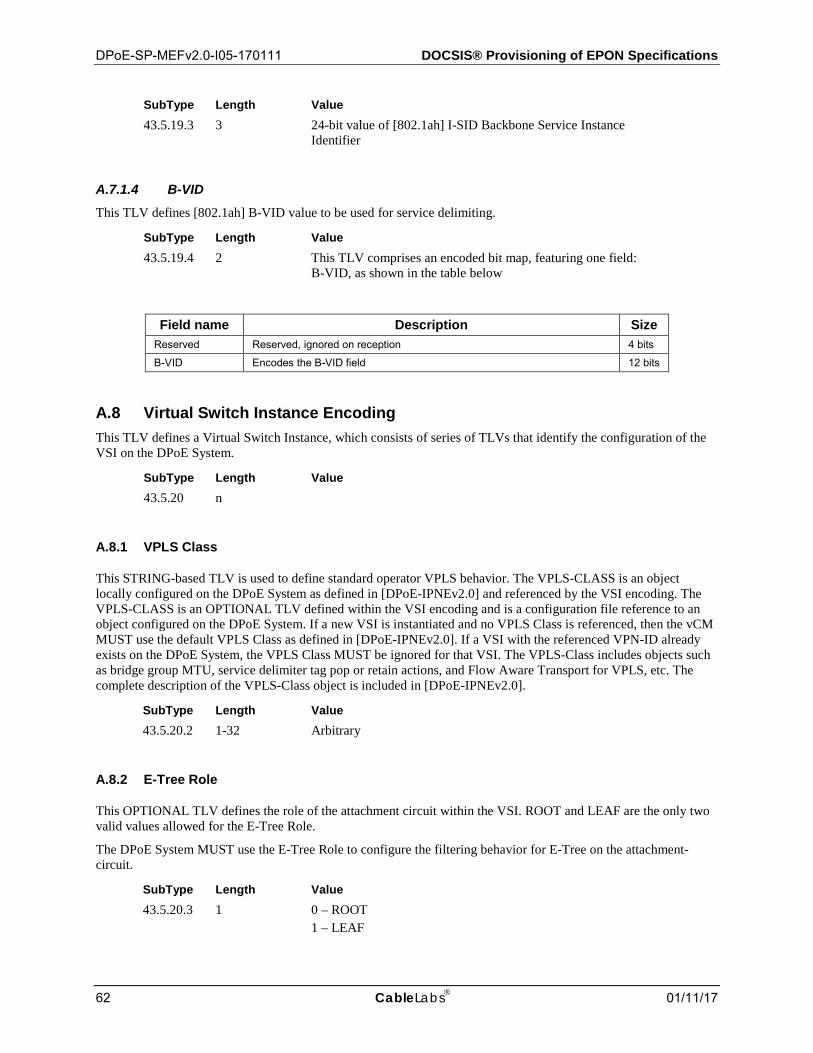
DPoE-SP-MEFv2.0-I05-170111 DOCSIS® Provisioning of EPON Specifications
62 CableLabs 01/11/17
SubType Length Value 43.5.19.3 3 24-bit value of [802.1ah] I-SID Backbone Service Instance
Identifier
B-VID A.7.1.4This TLV defines [802.1ah] B-VID value to be used for service delimiting.
SubType Length Value 43.5.19.4 2 This TLV comprises an encoded bit map, featuring one field:
B-VID, as shown in the table below
Field name Description Size Reserved Reserved, ignored on reception 4 bits
B-VID Encodes the B-VID field 12 bits
A.8 Virtual Switch Instance Encoding This TLV defines a Virtual Switch Instance, which consists of series of TLVs that identify the configuration of the VSI on the DPoE System.
SubType Length Value 43.5.20 n
A.8.1 VPLS Class
This STRING-based TLV is used to define standard operator VPLS behavior. The VPLS-CLASS is an object locally configured on the DPoE System as defined in [DPoE-IPNEv2.0] and referenced by the VSI encoding. The VPLS-CLASS is an OPTIONAL TLV defined within the VSI encoding and is a configuration file reference to an object configured on the DPoE System. If a new VSI is instantiated and no VPLS Class is referenced, then the vCM MUST use the default VPLS Class as defined in [DPoE-IPNEv2.0]. If a VSI with the referenced VPN-ID already exists on the DPoE System, the VPLS Class MUST be ignored for that VSI. The VPLS-Class includes objects such as bridge group MTU, service delimiter tag pop or retain actions, and Flow Aware Transport for VPLS, etc. The complete description of the VPLS-Class object is included in [DPoE-IPNEv2.0].
SubType Length Value 43.5.20.2 1-32 Arbitrary
A.8.2 E-Tree Role
This OPTIONAL TLV defines the role of the attachment circuit within the VSI. ROOT and LEAF are the only two valid values allowed for the E-Tree Role.
The DPoE System MUST use the E-Tree Role to configure the filtering behavior for E-Tree on the attachment-circuit.
SubType Length Value 43.5.20.3 1 0 – ROOT
1 – LEAF
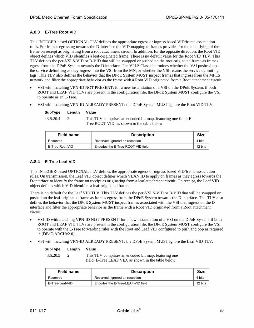
DPoE Metro Ethernet Forum Specification DPoE-SP-MEFv2.0-I05-170111
01/11/17 CableLabs 63
A.8.3 E-Tree Root VID
This INTEGER-based OPTIONAL TLV defines the appropriate egress or ingress based VID/frame association rules. For frames egressing towards the D-interface the VID mapping to frames provides for the identifying of the frame on receipt as originating from a root attachment circuit. In addition, for the opposite direction, the Root VID object defines which VID identifies a leaf-originated frame. There is no default value for the Root VID TLV. This TLV defines the per-VSI S-VID or B-VID that will be swapped or pushed on the root-originated frame as frames egress from the DPoE System towards the D interface. The VPLS Class determines whether the VSI pushes/pops the service delimiting as they ingress into the VSI from the MNI or whether the VSI retains the service delimiting tags. This TLV also defines the behavior that the DPoE System MUST inspect frames that ingress from the MPLS network and filter the appropriate behavior as the frame with a Root VID originated from a Root attachment circuit.
• VSI with matching VPN-ID NOT PRESENT: for a new instantiation of a VSI on the DPoE System, if both ROOT and LEAF VID TLVs are present in the configuration file, the DPoE System MUST configure the VSI to operate as an E-Tree.
• VSI with matching VPN-ID ALREADY PRESENT: the DPoE System MUST ignore the Root VID TLV.
SubType Length Value 43.5.20.4 2 This TLV comprises an encoded bit map, featuring one field: E-
Tree ROOT VID, as shown in the table below
Field name Description Size Reserved Reserved, ignored on reception 4 bits
E-Tree-Root-VID Encodes the E-Tree-ROOT-VID field 12 bits
A.8.4 E-Tree Leaf VID
This INTEGER-based OPTIONAL TLV defines the appropriate egress or ingress based VID/frame association rules. On transmission, the Leaf VID object defines which VLAN ID to apply on frames as they egress towards the D-interface to identify the frame on receipt as originating from a leaf attachment circuit. On receipt, the Leaf VID object defines which VID identifies a leaf-originated frame.
There is no default for the Leaf VID TLV. This TLV defines the per-VSI S-VID or B-VID that will be swapped or pushed on the leaf-originated frame as frames egress from the DPoE System towards the D interface. This TLV also defines the behavior that the DPoE System MUST inspect frames associated with the VSI that ingress on the D interface and filter the appropriate behavior as the frame with a Root VID originated from a Root attachment circuit.
• VSI-ID with matching VPN-ID NOT PRESENT: for a new instantiation of a VSI on the DPoE System, if both ROOT and LEAF VID TLVs are present in the configuration file, the DPoE System MUST configure the VSI to operate with the E-Tree forwarding rules with the Root and Leaf VID configured to push and pop as required in [DPoE-ARCHv2.0].
• VSI with matching VPN-ID ALREADY PRESENT: the DPoE System MUST ignore the Leaf VID TLV.
SubType Length Value 43.5.20.5 2 This TLV comprises an encoded bit map, featuring one
field: E-Tree LEAF VID, as shown in the table below
Field name Description Size Reserved Reserved, ignored on reception 4 bits
E-Tree-Leaf-VID Encodes the E-Tree-LEAF-VID field 12 bits
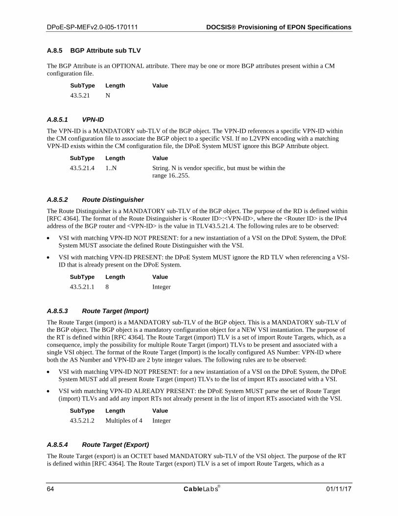
DPoE-SP-MEFv2.0-I05-170111 DOCSIS® Provisioning of EPON Specifications
64 CableLabs 01/11/17
A.8.5 BGP Attribute sub TLV
The BGP Attribute is an OPTIONAL attribute. There may be one or more BGP attributes present within a CM configuration file.
SubType Length Value 43.5.21 N
VPN-ID A.8.5.1The VPN-ID is a MANDATORY sub-TLV of the BGP object. The VPN-ID references a specific VPN-ID within the CM configuration file to associate the BGP object to a specific VSI. If no L2VPN encoding with a matching VPN-ID exists within the CM configuration file, the DPoE System MUST ignore this BGP Attribute object.
SubType Length Value 43.5.21.4 1..N String. N is vendor specific, but must be within the
range 16..255.
Route Distinguisher A.8.5.2The Route Distinguisher is a MANDATORY sub-TLV of the BGP object. The purpose of the RD is defined within [RFC 4364]. The format of the Route Distinguisher is <Router ID>:<VPN-ID>, where the <Router ID> is the IPv4 address of the BGP router and <VPN-ID> is the value in TLV43.5.21.4. The following rules are to be observed:
• VSI with matching VPN-ID NOT PRESENT: for a new instantiation of a VSI on the DPoE System, the DPoE System MUST associate the defined Route Distinguisher with the VSI.
• VSI with matching VPN-ID PRESENT: the DPoE System MUST ignore the RD TLV when referencing a VSI-ID that is already present on the DPoE System.
SubType Length Value 43.5.21.1 8 Integer
Route Target (Import) A.8.5.3The Route Target (import) is a MANDATORY sub-TLV of the BGP object. This is a MANDATORY sub-TLV of the BGP object. The BGP object is a mandatory configuration object for a NEW VSI instantiation. The purpose of the RT is defined within [RFC 4364]. The Route Target (import) TLV is a set of import Route Targets, which, as a consequence, imply the possibility for multiple Route Target (import) TLVs to be present and associated with a single VSI object. The format of the Route Target (Import) is the locally configured AS Number: VPN-ID where both the AS Number and VPN-ID are 2 byte integer values. The following rules are to be observed:
• VSI with matching VPN-ID NOT PRESENT: for a new instantiation of a VSI on the DPoE System, the DPoE System MUST add all present Route Target (import) TLVs to the list of import RTs associated with a VSI.
• VSI with matching VPN-ID ALREADY PRESENT: the DPoE System MUST parse the set of Route Target (import) TLVs and add any import RTs not already present in the list of import RTs associated with the VSI.
SubType Length Value 43.5.21.2 Multiples of 4 Integer
Route Target (Export) A.8.5.4The Route Target (export) is an OCTET based MANDATORY sub-TLV of the VSI object. The purpose of the RT is defined within [RFC 4364]. The Route Target (export) TLV is a set of import Route Targets, which as a
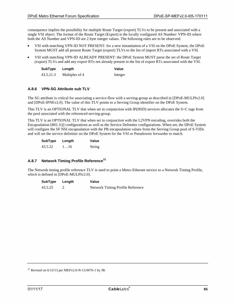
DPoE Metro Ethernet Forum Specification DPoE-SP-MEFv2.0-I05-170111
01/11/17 CableLabs 65
consequence implies the possibility for multiple Route Target (export) TLVs to be present and associated with a single VSI object. The format of the Route Target (Export) is the locally configured AS Number: VPN-ID where both the AS Number and VPN-ID are 2 byte integer values. The following rules are to be observed:
• VSI with matching VPN-ID NOT PRESENT: for a new instantiation of a VSI on the DPoE System, the DPoE System MUST add all present Route Target (export) TLVs to the list of import RTs associated with a VSI.
• VSI with matching VPN-ID ALREADY PRESENT: the DPoE System MUST parse the set of Route Target (export) TLVs and add any export RTs not already present in the list of export RTs associated with the VSI.
SubType Length Value 43.5.21.3 Multiples of 4 Integer
A.8.6 VPN-SG Attribute sub TLV
The SG attribute is critical for associating a service-flow with a serving-group as described in [DPoE-MULPIv2.0] and [DPoE-IPNEv2.0]. The value of this TLV points to a Serving Group identifier on the DPoE System.
This TLV is an OPTIONAL TLV that when set in conjunction with IP(HSD) services allocates the S+C tags from the pool associated with the referenced serving-group.
This TLV is an OPTIONAL TLV that when set in conjunction with the L2VPN encoding, overrides both the Encapsulation [802.1Q] configurations as well as the Service Delimiter configurations. When set, the DPoE System will configure the SF NSI encapsulation with the PB encapsulation values from the Serving Group pool of S-VIDs and will set the service delimiter on the DPoE System for the VSI or Pseudowire forwarder to match.
SubType Length Value 43.5.22 1…16 String
A.8.7 Network Timing Profile Reference21
The Network timing profile reference TLV is used to point a Metro Ethernet service to a Network Timing Profile, which is defined in [DPoE-MULPIv2.0].
SubType Length Value 43.5.25 2 Network Timing Profile Reference
21 Revised on 6/13/13 per MEFv2.0-N-13.0076-1 by JB.
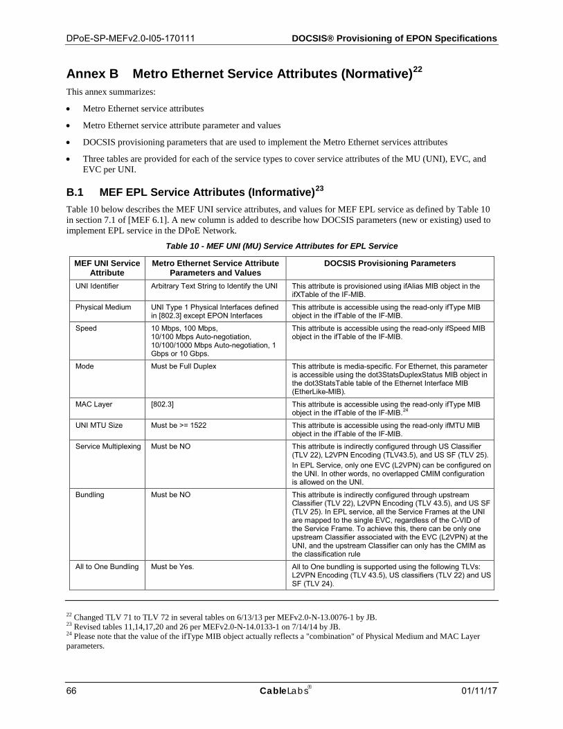
DPoE-SP-MEFv2.0-I05-170111 DOCSIS® Provisioning of EPON Specifications
66 CableLabs 01/11/17
Annex B Metro Ethernet Service Attributes (Normative)22 This annex summarizes:
• Metro Ethernet service attributes
• Metro Ethernet service attribute parameter and values
• DOCSIS provisioning parameters that are used to implement the Metro Ethernet services attributes
• Three tables are provided for each of the service types to cover service attributes of the MU (UNI), EVC, and EVC per UNI.
B.1 MEF EPL Service Attributes (Informative)23 Table 10 below describes the MEF UNI service attributes, and values for MEF EPL service as defined by Table 10 in section 7.1 of [MEF 6.1]. A new column is added to describe how DOCSIS parameters (new or existing) used to implement EPL service in the DPoE Network.
Table 10 - MEF UNI (MU) Service Attributes for EPL Service
MEF UNI Service Attribute
Metro Ethernet Service Attribute Parameters and Values
DOCSIS Provisioning Parameters
UNI Identifier Arbitrary Text String to Identify the UNI This attribute is provisioned using ifAlias MIB object in the ifXTable of the IF-MIB.
Physical Medium UNI Type 1 Physical Interfaces defined in [802.3] except EPON Interfaces
This attribute is accessible using the read-only ifType MIB object in the ifTable of the IF-MIB.
Speed 10 Mbps, 100 Mbps, 10/100 Mbps Auto-negotiation, 10/100/1000 Mbps Auto-negotiation, 1 Gbps or 10 Gbps.
This attribute is accessible using the read-only ifSpeed MIB object in the ifTable of the IF-MIB.
Mode Must be Full Duplex This attribute is media-specific. For Ethernet, this parameter is accessible using the dot3StatsDuplexStatus MIB object in the dot3StatsTable table of the Ethernet Interface MIB (EtherLike-MIB).
MAC Layer [802.3] This attribute is accessible using the read-only ifType MIB object in the ifTable of the IF-MIB.24
UNI MTU Size Must be >= 1522 This attribute is accessible using the read-only ifMTU MIB object in the ifTable of the IF-MIB.
Service Multiplexing Must be NO This attribute is indirectly configured through US Classifier (TLV 22), L2VPN Encoding (TLV43.5), and US SF (TLV 25). In EPL Service, only one EVC (L2VPN) can be configured on the UNI. In other words, no overlapped CMIM configuration is allowed on the UNI.
Bundling Must be NO This attribute is indirectly configured through upstream Classifier (TLV 22), L2VPN Encoding (TLV 43.5), and US SF (TLV 25). In EPL service, all the Service Frames at the UNI are mapped to the single EVC, regardless of the C-VID of the Service Frame. To achieve this, there can be only one upstream Classifier associated with the EVC (L2VPN) at the UNI, and the upstream Classifier can only has the CMIM as the classification rule
All to One Bundling Must be Yes. All to One bundling is supported using the following TLVs: L2VPN Encoding (TLV 43.5), US classifiers (TLV 22) and US SF (TLV 24).
22 Changed TLV 71 to TLV 72 in several tables on 6/13/13 per MEFv2.0-N-13.0076-1 by JB. 23 Revised tables 11,14,17,20 and 26 per MEFv2.0-N-14.0133-1 on 7/14/14 by JB. 24 Please note that the value of the ifType MIB object actually reflects a "combination" of Physical Medium and MAC Layer parameters.
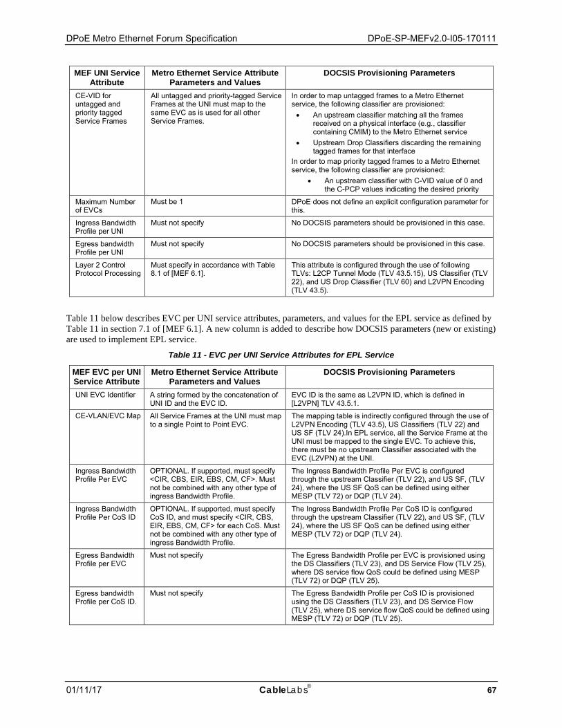
DPoE Metro Ethernet Forum Specification DPoE-SP-MEFv2.0-I05-170111
01/11/17 CableLabs 67
MEF UNI Service Attribute
Metro Ethernet Service Attribute Parameters and Values
DOCSIS Provisioning Parameters
CE-VID for untagged and priority tagged Service Frames
All untagged and priority-tagged Service Frames at the UNI must map to the same EVC as is used for all other Service Frames.
In order to map untagged frames to a Metro Ethernet service, the following classifier are provisioned: • An upstream classifier matching all the frames
received on a physical interface (e.g., classifier containing CMIM) to the Metro Ethernet service
• Upstream Drop Classifiers discarding the remaining tagged frames for that interface
In order to map priority tagged frames to a Metro Ethernet service, the following classifier are provisioned:
• An upstream classifier with C-VID value of 0 and the C-PCP values indicating the desired priority
Maximum Number of EVCs
Must be 1 DPoE does not define an explicit configuration parameter for this.
Ingress Bandwidth Profile per UNI
Must not specify No DOCSIS parameters should be provisioned in this case.
Egress bandwidth Profile per UNI
Must not specify No DOCSIS parameters should be provisioned in this case.
Layer 2 Control Protocol Processing
Must specify in accordance with Table 8.1 of [MEF 6.1].
This attribute is configured through the use of following TLVs: L2CP Tunnel Mode (TLV 43.5.15), US Classifier (TLV 22), and US Drop Classifier (TLV 60) and L2VPN Encoding (TLV 43.5).
Table 11 below describes EVC per UNI service attributes, parameters, and values for the EPL service as defined by Table 11 in section 7.1 of [MEF 6.1]. A new column is added to describe how DOCSIS parameters (new or existing) are used to implement EPL service.
Table 11 - EVC per UNI Service Attributes for EPL Service
MEF EVC per UNI Service Attribute
Metro Ethernet Service Attribute Parameters and Values
DOCSIS Provisioning Parameters
UNI EVC Identifier A string formed by the concatenation of UNI ID and the EVC ID.
EVC ID is the same as L2VPN ID, which is defined in [L2VPN] TLV 43.5.1.
CE-VLAN/EVC Map All Service Frames at the UNI must map to a single Point to Point EVC.
The mapping table is indirectly configured through the use of L2VPN Encoding (TLV 43.5), US Classifiers (TLV 22) and US SF (TLV 24).In EPL service, all the Service Frame at the UNI must be mapped to the single EVC. To achieve this, there must be no upstream Classifier associated with the EVC (L2VPN) at the UNI.
Ingress Bandwidth Profile Per EVC
OPTIONAL. If supported, must specify <CIR, CBS, EIR, EBS, CM, CF>. Must not be combined with any other type of ingress Bandwidth Profile.
The Ingress Bandwidth Profile Per EVC is configured through the upstream Classifier (TLV 22), and US SF, (TLV 24), where the US SF QoS can be defined using either MESP (TLV 72) or DQP (TLV 24).
Ingress Bandwidth Profile Per CoS ID
OPTIONAL. If supported, must specify CoS ID, and must specify <CIR, CBS, EIR, EBS, CM, CF> for each CoS. Must not be combined with any other type of ingress Bandwidth Profile.
The Ingress Bandwidth Profile Per CoS ID is configured through the upstream Classifier (TLV 22), and US SF, (TLV 24), where the US SF QoS can be defined using either MESP (TLV 72) or DQP (TLV 24).
Egress Bandwidth Profile per EVC
Must not specify The Egress Bandwidth Profile per EVC is provisioned using the DS Classifiers (TLV 23), and DS Service Flow (TLV 25), where DS service flow QoS could be defined using MESP (TLV 72) or DQP (TLV 25).
Egress bandwidth Profile per CoS ID.
Must not specify The Egress Bandwidth Profile per CoS ID is provisioned using the DS Classifiers (TLV 23), and DS Service Flow (TLV 25), where DS service flow QoS could be defined using MESP (TLV 72) or DQP (TLV 25).
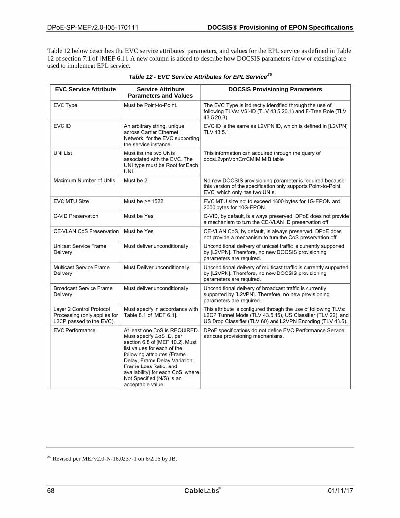
DPoE-SP-MEFv2.0-I05-170111 DOCSIS® Provisioning of EPON Specifications
68 CableLabs 01/11/17
Table 12 below describes the EVC service attributes, parameters, and values for the EPL service as defined in Table 12 of section 7.1 of [MEF 6.1]. A new column is added to describe how DOCSIS parameters (new or existing) are used to implement EPL service.
Table 12 - EVC Service Attributes for EPL Service25
EVC Service Attribute Service Attribute Parameters and Values
DOCSIS Provisioning Parameters
EVC Type Must be Point-to-Point. The EVC Type is indirectly identified through the use of following TLVs: VSI-ID (TLV 43.5.20.1) and E-Tree Role (TLV 43.5.20.3).
EVC ID An arbitrary string, unique across Carrier Ethernet Network, for the EVC supporting the service instance.
EVC ID is the same as L2VPN ID, which is defined in [L2VPN] TLV 43.5.1.
UNI List Must list the two UNIs associated with the EVC. The UNI type must be Root for Each UNI.
This information can acquired through the query of docsL2vpnVpnCmCMIM MIB table
Maximum Number of UNIs. Must be 2. No new DOCSIS provisioning parameter is required because this version of the specification only supports Point-to-Point EVC, which only has two UNIs.
EVC MTU Size Must be >= 1522. EVC MTU size not to exceed 1600 bytes for 1G-EPON and 2000 bytes for 10G-EPON.
C-VID Preservation Must be Yes. C-VID, by default, is always preserved. DPoE does not provide a mechanism to turn the CE-VLAN ID preservation off.
CE-VLAN CoS Preservation Must be Yes. CE-VLAN CoS, by default, is always preserved. DPoE does not provide a mechanism to turn the CoS preservation off.
Unicast Service Frame Delivery
Must deliver unconditionally. Unconditional delivery of unicast traffic is currently supported by [L2VPN]. Therefore, no new DOCSIS provisioning parameters are required.
Multicast Service Frame Delivery
Must Deliver unconditionally. Unconditional delivery of multicast traffic is currently supported by [L2VPN]. Therefore, no new DOCSIS provisioning parameters are required.
Broadcast Service Frame Delivery
Must deliver unconditionally. Unconditional delivery of broadcast traffic is currently supported by [L2VPN]. Therefore, no new provisioning parameters are required.
Layer 2 Control Protocol Processing (only applies for L2CP passed to the EVC).
Must specify in accordance with Table 8.1 of [MEF 6.1].
This attribute is configured through the use of following TLVs: L2CP Tunnel Mode (TLV 43.5.15), US Classifier (TLV 22), and US Drop Classifier (TLV 60) and L2VPN Encoding (TLV 43.5).
EVC Performance At least one CoS is REQUIRED. Must specify CoS ID, per section 6.8 of [MEF 10.2]. Must list values for each of the following attributes {Frame Delay, Frame Delay Variation, Frame Loss Ratio, and availability} for each CoS, where Not Specified (N/S) is an acceptable value.
DPoE specifications do not define EVC Performance Service attribute provisioning mechanisms.
25 Revised per MEFv2.0-N-16.0237-1 on 6/2/16 by JB.
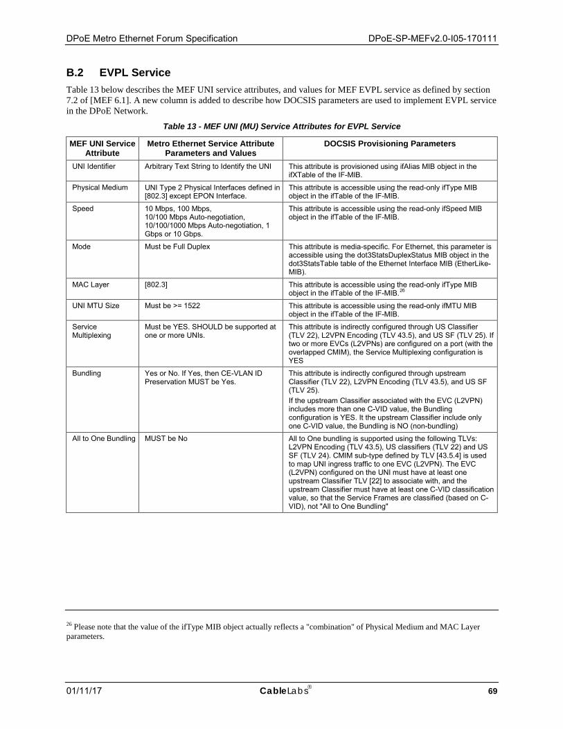
DPoE Metro Ethernet Forum Specification DPoE-SP-MEFv2.0-I05-170111
01/11/17 CableLabs 69
B.2 EVPL Service Table 13 below describes the MEF UNI service attributes, and values for MEF EVPL service as defined by section 7.2 of [MEF 6.1]. A new column is added to describe how DOCSIS parameters are used to implement EVPL service in the DPoE Network.
Table 13 - MEF UNI (MU) Service Attributes for EVPL Service
MEF UNI Service Attribute
Metro Ethernet Service Attribute Parameters and Values
DOCSIS Provisioning Parameters
UNI Identifier Arbitrary Text String to Identify the UNI This attribute is provisioned using ifAlias MIB object in the ifXTable of the IF-MIB.
Physical Medium UNI Type 2 Physical Interfaces defined in [802.3] except EPON Interface.
This attribute is accessible using the read-only ifType MIB object in the ifTable of the IF-MIB.
Speed 10 Mbps, 100 Mbps, 10/100 Mbps Auto-negotiation, 10/100/1000 Mbps Auto-negotiation, 1 Gbps or 10 Gbps.
This attribute is accessible using the read-only ifSpeed MIB object in the ifTable of the IF-MIB.
Mode Must be Full Duplex This attribute is media-specific. For Ethernet, this parameter is accessible using the dot3StatsDuplexStatus MIB object in the dot3StatsTable table of the Ethernet Interface MIB (EtherLike-MIB).
MAC Layer [802.3] This attribute is accessible using the read-only ifType MIB object in the ifTable of the IF-MIB.26
UNI MTU Size Must be >= 1522 This attribute is accessible using the read-only ifMTU MIB object in the ifTable of the IF-MIB.
Service Multiplexing
Must be YES. SHOULD be supported at one or more UNIs.
This attribute is indirectly configured through US Classifier (TLV 22), L2VPN Encoding (TLV 43.5), and US SF (TLV 25). If two or more EVCs (L2VPNs) are configured on a port (with the overlapped CMIM), the Service Multiplexing configuration is YES
Bundling Yes or No. If Yes, then CE-VLAN ID Preservation MUST be Yes.
This attribute is indirectly configured through upstream Classifier (TLV 22), L2VPN Encoding (TLV 43.5), and US SF (TLV 25). If the upstream Classifier associated with the EVC (L2VPN) includes more than one C-VID value, the Bundling configuration is YES. It the upstream Classifier include only one C-VID value, the Bundling is NO (non-bundling)
All to One Bundling MUST be No All to One bundling is supported using the following TLVs: L2VPN Encoding (TLV 43.5), US classifiers (TLV 22) and US SF (TLV 24). CMIM sub-type defined by TLV [43.5.4] is used to map UNI ingress traffic to one EVC (L2VPN). The EVC (L2VPN) configured on the UNI must have at least one upstream Classifier TLV [22] to associate with, and the upstream Classifier must have at least one C-VID classification value, so that the Service Frames are classified (based on C-VID), not "All to One Bundling"
26 Please note that the value of the ifType MIB object actually reflects a "combination" of Physical Medium and MAC Layer parameters.
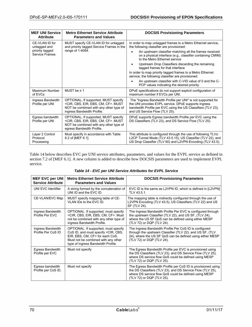
DPoE-SP-MEFv2.0-I05-170111 DOCSIS® Provisioning of EPON Specifications
70 CableLabs 01/11/17
MEF UNI Service Attribute
Metro Ethernet Service Attribute Parameters and Values
DOCSIS Provisioning Parameters
CE-VLAN ID for untagged and priority tagged Service Frames
MUST specify CE-VLAN ID for untagged and priority tagged Service Frames in the range of 1-4094.
In order to map untagged frames to a Metro Ethernet service, the following classifier are provisioned: • An upstream classifier matching all the frames received
on a physical interface (e.g., classifier containing CMIM) to the Metro Ethernet service
• Upstream Drop Classifiers discarding the remaining tagged frames for that interface
In order to map priority tagged frames to a Metro Ethernet service, the following classifier are provisioned: • An upstream classifier with C-VID value of 0 and the C-
PCP values indicating the desired priority
Maximum Number of EVCs
MUST be ≥ 1 DPoE specifications do not support explicit configuration of maximum number if EVCs per UNI.
Ingress Bandwidth Profile per UNI
OPTIONAL. If supported, MUST specify <CIR, CBS, EIR, EBS, CM, CF>. MUST NOT be combined with any other type of ingress Bandwidth Profile.
The "Ingress Bandwidth Profile per UNI" is not supported for the UNI provides EVPL service. DPoE supports Ingress bandwidth Profile per EVC using the US Classifiers (TLV 23), and US Service Flow (TLV 25).
Egress bandwidth Profile per UNI
OPTIONAL. If supported, MUST specify <CIR, CBS, EIR, EBS, CM, CF>. MUST NOT be combined with any other type of egress Bandwidth Profile.
DPoE supports Egress bandwidth Profile per EVC using the DS Classifiers (TLV 23), and DS Service Flow (TLV 25).
Layer 2 Control Protocol Processing
Must specify in accordance with Table 8.2 of [MEF 6.1].
This attribute is configured through the use of following TLVs: L2CP Tunnel Mode (TLV 43.5.15), US Classifier (TLV 22), and US Drop Classifier (TLV 60) and L2VPN Encoding (TLV 43.5).
Table 14 below describes EVC per UNI service attributes, parameters, and values for the EVPL service as defined in section 7.2 of [MEF 6.1]. A new column is added to describe how DOCSIS parameters are used to implement EVPL service.
Table 14 - EVC per UNI Service Attributes for EVPL Service
MEF EVC per UNI Service Attribute
Metro Ethernet Service Attribute Parameters and Values
DOCSIS Provisioning Parameters
UNI EVC Identifier A string formed by the concatenation of UNI ID and the EVC ID.
EVC ID is the same as L2VPN ID, which is defined in [L2VPN] TLV 43.5.1.
CE-VLAN/EVC Map MUST specify mapping table of CE-VLAN IDs to the EVC ID.
The mapping table is indirectly configured through the use of L2VPN Encoding (TLV 43.5), US Classifiers (TLV 22) and US SF (TLV 24).
Ingress Bandwidth Profile Per EVC
OPTIONAL. If supported, must specify <CIR, CBS, EIR, EBS, CM, CF>. Must not be combined with any other type of ingress Bandwidth Profile.
The Ingress Bandwidth Profile Per EVC is configured through the upstream Classifier (TLV 22), and US SF, (TLV 24), where the US SF QoS can be defined using either MESP (TLV 72) or DQP (TLV 24).
Ingress Bandwidth Profile Per CoS ID
OPTIONAL. If supported, must specify CoS ID, and must specify <CIR, CBS, EIR, EBS, CM, CF> for each CoS. Must not be combined with any other type of ingress Bandwidth Profile.
The Ingress Bandwidth Profile Per CoS ID is configured through the upstream Classifier (TLV 22), and US SF, (TLV 24), where the US SF QoS can be defined using either MESP (TLV 72) or DQP (TLV 24).
Egress Bandwidth Profile per EVC
Must not specify The Egress Bandwidth Profile per EVC is provisioned using the DS Classifiers (TLV 23), and DS Service Flow (TLV 25), where DS service flow QoS could be defined using MESP (TLV 72) or DQP (TLV 25).
Egress bandwidth Profile per CoS ID.
Must not specify The Egress Bandwidth Profile per CoS ID is provisioned using the DS Classifiers (TLV 23), and DS Service Flow (TLV 25), where DS service flow QoS could be defined using MESP (TLV 72) or DQP (TLV 25).
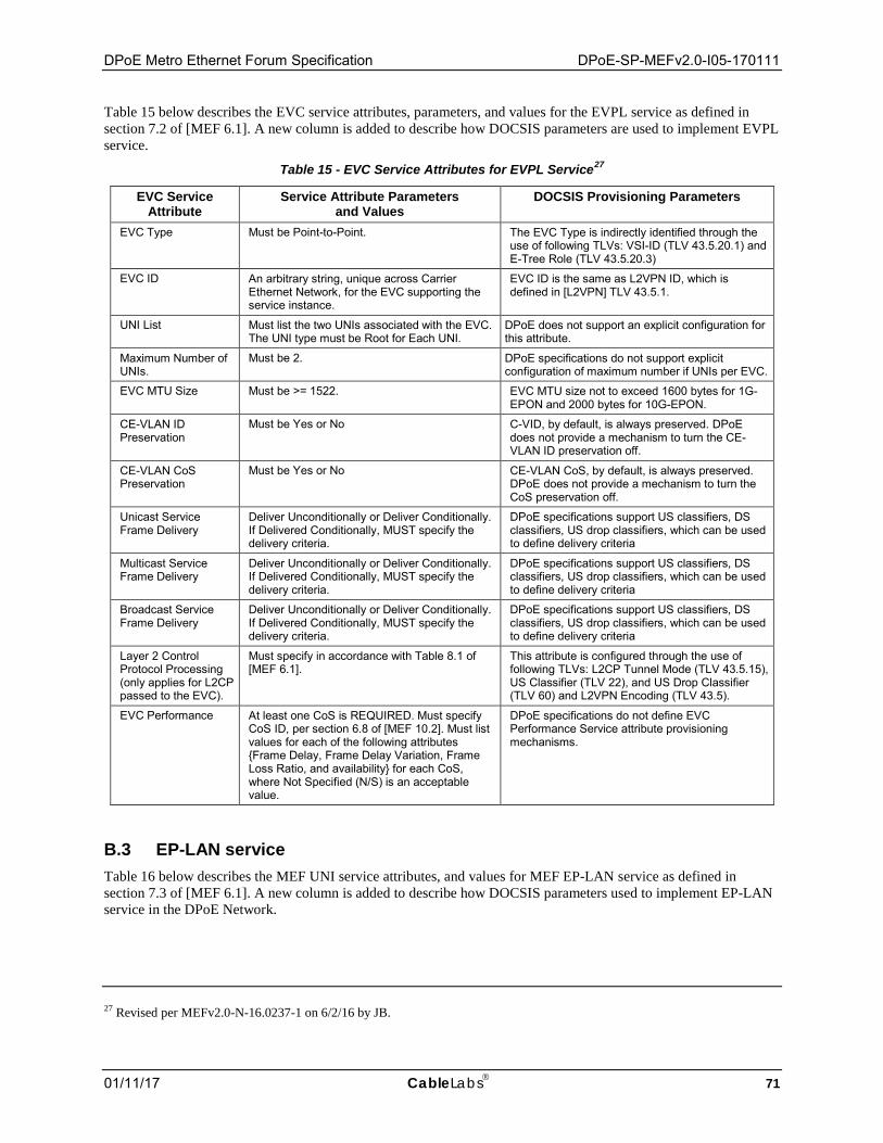
DPoE Metro Ethernet Forum Specification DPoE-SP-MEFv2.0-I05-170111
01/11/17 CableLabs 71
Table 15 below describes the EVC service attributes, parameters, and values for the EVPL service as defined in section 7.2 of [MEF 6.1]. A new column is added to describe how DOCSIS parameters are used to implement EVPL service.
Table 15 - EVC Service Attributes for EVPL Service27
EVC Service Attribute
Service Attribute Parameters and Values
DOCSIS Provisioning Parameters
EVC Type Must be Point-to-Point. The EVC Type is indirectly identified through the use of following TLVs: VSI-ID (TLV 43.5.20.1) and E-Tree Role (TLV 43.5.20.3)
EVC ID An arbitrary string, unique across Carrier Ethernet Network, for the EVC supporting the service instance.
EVC ID is the same as L2VPN ID, which is defined in [L2VPN] TLV 43.5.1.
UNI List Must list the two UNIs associated with the EVC. The UNI type must be Root for Each UNI.
DPoE does not support an explicit configuration for this attribute.
Maximum Number of UNIs.
Must be 2. DPoE specifications do not support explicit configuration of maximum number if UNIs per EVC.
EVC MTU Size Must be >= 1522. EVC MTU size not to exceed 1600 bytes for 1G-EPON and 2000 bytes for 10G-EPON.
CE-VLAN ID Preservation
Must be Yes or No C-VID, by default, is always preserved. DPoE does not provide a mechanism to turn the CE-VLAN ID preservation off.
CE-VLAN CoS Preservation
Must be Yes or No CE-VLAN CoS, by default, is always preserved. DPoE does not provide a mechanism to turn the CoS preservation off.
Unicast Service Frame Delivery
Deliver Unconditionally or Deliver Conditionally. If Delivered Conditionally, MUST specify the delivery criteria.
DPoE specifications support US classifiers, DS classifiers, US drop classifiers, which can be used to define delivery criteria
Multicast Service Frame Delivery
Deliver Unconditionally or Deliver Conditionally. If Delivered Conditionally, MUST specify the delivery criteria.
DPoE specifications support US classifiers, DS classifiers, US drop classifiers, which can be used to define delivery criteria
Broadcast Service Frame Delivery
Deliver Unconditionally or Deliver Conditionally. If Delivered Conditionally, MUST specify the delivery criteria.
DPoE specifications support US classifiers, DS classifiers, US drop classifiers, which can be used to define delivery criteria
Layer 2 Control Protocol Processing (only applies for L2CP passed to the EVC).
Must specify in accordance with Table 8.1 of [MEF 6.1].
This attribute is configured through the use of following TLVs: L2CP Tunnel Mode (TLV 43.5.15), US Classifier (TLV 22), and US Drop Classifier (TLV 60) and L2VPN Encoding (TLV 43.5).
EVC Performance At least one CoS is REQUIRED. Must specify CoS ID, per section 6.8 of [MEF 10.2]. Must list values for each of the following attributes {Frame Delay, Frame Delay Variation, Frame Loss Ratio, and availability} for each CoS, where Not Specified (N/S) is an acceptable value.
DPoE specifications do not define EVC Performance Service attribute provisioning mechanisms.
B.3 EP-LAN service Table 16 below describes the MEF UNI service attributes, and values for MEF EP-LAN service as defined in section 7.3 of [MEF 6.1]. A new column is added to describe how DOCSIS parameters used to implement EP-LAN service in the DPoE Network.
27 Revised per MEFv2.0-N-16.0237-1 on 6/2/16 by JB.

DPoE-SP-MEFv2.0-I05-170111 DOCSIS® Provisioning of EPON Specifications
72 CableLabs 01/11/17
Table 16 - MEF UNI (MU) Service Attributes for EP-LAN Service
MEF UNI Service Attribute
Metro Ethernet Service Attribute Parameters and Values
DOCSIS Provisioning Parameters
UNI Identifier Arbitrary Text String to Identify the UNI
This attribute is provisioned using ifAlias MIB object in the ifXTable of the IF-MIB.
Physical Medium UNI Type 2 Physical Interfaces defined in [802.3] except EPON Interfaces
This attribute is accessible using the read-only ifType MIB object in the ifTable of the IF-MIB.
Speed 10 Mbps, 100 Mbps, 10/100 Mbps Auto-negotiation, 10/100/1000 Mbps Auto-negotiation, 1 Gbps or 10 Gbps.
This attribute is accessible using the read-only ifSpeed MIB object in the ifTable of the IF-MIB.
Mode Must be Full Duplex This attribute is media-specific. For Ethernet, this parameter is accessible using the dot3StatsDuplexStatus MIB object in the dot3StatsTable table of the Ethernet Interface MIB (EtherLike-MIB).
MAC Layer [802.3] This attribute is accessible using the read-only ifType MIB object in the ifTable of the IF-MIB.
UNI MTU Size Must be >= 1522 This attribute is accessible using the read-only ifMTU MIB object in the ifTable of the IF-MIB.
Service Multiplexing Must be No This attribute is indirectly configured through US Classifier (TLV 22), L2VPN Encoding (TLV 43.5), and US SF (TLV 25). In EP-LAN Service, only one EVC (L2VPN) can be configured on the UNI. In other words, no overlapped CMIM configuration is allowed on the UNI.
Bundling Must be No This attribute is indirectly configured through upstream Classifier (TLV 22), L2VPN Encoding (TLV 43.5), and US SF (TLV 25).
All to One Bundling MUST be Yes All to One bundling is supported using the following TLVs: L2VPN Encoding (TLV 43.5), US classifiers (TLV 22) and US SF (TLV 24).
CE-VLAN ID for untagged and priority tagged Service Frames
All untagged and priority tagged Service Frames at the UNI MUST map to the same EVC as is used for all other Service Frames
In order to map untagged frames to a Metro Ethernet service, the following classifier are provisioned: • An upstream classifier matching all the frames received
on a physical interface (e.g., classifier containing CMIM) to the Metro Ethernet service
• Upstream Drop Classifiers discarding the remaining tagged frames for that interface
In order to map priority tagged frames to a Metro Ethernet service, the following classifier are provisioned: • An upstream classifier with C-VID value of 0 and the C-
PCP values indicating the desired priority
Maximum Number of EVCs
MUST be 1 DPoE specifications do not support explicit configuration of maximum number if EVCs per UNI.
Ingress Bandwidth Profile per UNI
Must not specify No DOCSIS parameters should be provisioned in this case.
Egress bandwidth Profile per UNI
Must not specify No DOCSIS parameters should be provisioned in this case.
Layer 2 Control Protocol Processing
Must specify in accordance with Table 8.2 of [MEF 6.1].
This attribute is configured through the use of following TLVs: L2CP Tunnel Mode (TLV 43.5.15), US Classifier (TLV 22), and US Drop Classifier (TLV 60) and L2VPN Encoding (TLV 43.5).
Table 17 below describes EVC per UNI service attributes, parameters, and values for the EP-LAN service as defined in section 7.3 of [MEF 6.1]. A new column is added to describe how DOCSIS parameters used to implement EP-LAN service.
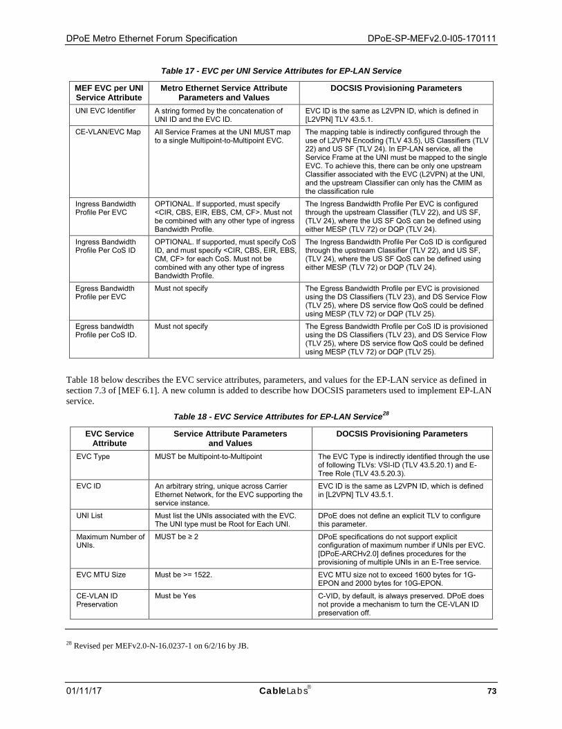
DPoE Metro Ethernet Forum Specification DPoE-SP-MEFv2.0-I05-170111
01/11/17 CableLabs 73
Table 17 - EVC per UNI Service Attributes for EP-LAN Service
MEF EVC per UNI Service Attribute
Metro Ethernet Service Attribute Parameters and Values
DOCSIS Provisioning Parameters
UNI EVC Identifier A string formed by the concatenation of UNI ID and the EVC ID.
EVC ID is the same as L2VPN ID, which is defined in [L2VPN] TLV 43.5.1.
CE-VLAN/EVC Map All Service Frames at the UNI MUST map to a single Multipoint-to-Multipoint EVC.
The mapping table is indirectly configured through the use of L2VPN Encoding (TLV 43.5), US Classifiers (TLV 22) and US SF (TLV 24). In EP-LAN service, all the Service Frame at the UNI must be mapped to the single EVC. To achieve this, there can be only one upstream Classifier associated with the EVC (L2VPN) at the UNI, and the upstream Classifier can only has the CMIM as the classification rule
Ingress Bandwidth Profile Per EVC
OPTIONAL. If supported, must specify <CIR, CBS, EIR, EBS, CM, CF>. Must not be combined with any other type of ingress Bandwidth Profile.
The Ingress Bandwidth Profile Per EVC is configured through the upstream Classifier (TLV 22), and US SF, (TLV 24), where the US SF QoS can be defined using either MESP (TLV 72) or DQP (TLV 24).
Ingress Bandwidth Profile Per CoS ID
OPTIONAL. If supported, must specify CoS ID, and must specify <CIR, CBS, EIR, EBS, CM, CF> for each CoS. Must not be combined with any other type of ingress Bandwidth Profile.
The Ingress Bandwidth Profile Per CoS ID is configured through the upstream Classifier (TLV 22), and US SF, (TLV 24), where the US SF QoS can be defined using either MESP (TLV 72) or DQP (TLV 24).
Egress Bandwidth Profile per EVC
Must not specify The Egress Bandwidth Profile per EVC is provisioned using the DS Classifiers (TLV 23), and DS Service Flow (TLV 25), where DS service flow QoS could be defined using MESP (TLV 72) or DQP (TLV 25).
Egress bandwidth Profile per CoS ID.
Must not specify The Egress Bandwidth Profile per CoS ID is provisioned using the DS Classifiers (TLV 23), and DS Service Flow (TLV 25), where DS service flow QoS could be defined using MESP (TLV 72) or DQP (TLV 25).
Table 18 below describes the EVC service attributes, parameters, and values for the EP-LAN service as defined in section 7.3 of [MEF 6.1]. A new column is added to describe how DOCSIS parameters used to implement EP-LAN service.
Table 18 - EVC Service Attributes for EP-LAN Service28
EVC Service Attribute
Service Attribute Parameters and Values
DOCSIS Provisioning Parameters
EVC Type MUST be Multipoint-to-Multipoint The EVC Type is indirectly identified through the use of following TLVs: VSI-ID (TLV 43.5.20.1) and E-Tree Role (TLV 43.5.20.3).
EVC ID An arbitrary string, unique across Carrier Ethernet Network, for the EVC supporting the service instance.
EVC ID is the same as L2VPN ID, which is defined in [L2VPN] TLV 43.5.1.
UNI List Must list the UNIs associated with the EVC. The UNI type must be Root for Each UNI.
DPoE does not define an explicit TLV to configure this parameter.
Maximum Number of UNIs.
MUST be ≥ 2 DPoE specifications do not support explicit configuration of maximum number if UNIs per EVC. [DPoE-ARCHv2.0] defines procedures for the provisioning of multiple UNIs in an E-Tree service.
EVC MTU Size Must be >= 1522. EVC MTU size not to exceed 1600 bytes for 1G-EPON and 2000 bytes for 10G-EPON.
CE-VLAN ID Preservation
Must be Yes C-VID, by default, is always preserved. DPoE does not provide a mechanism to turn the CE-VLAN ID preservation off.
28 Revised per MEFv2.0-N-16.0237-1 on 6/2/16 by JB.
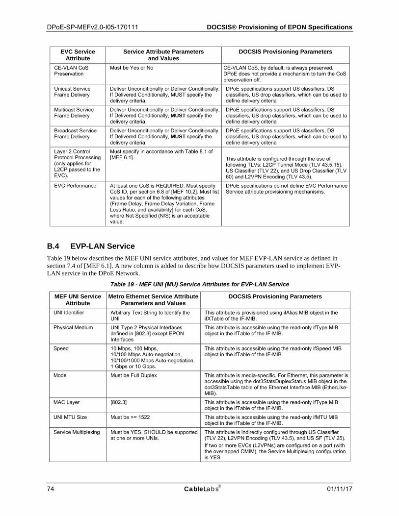
DPoE-SP-MEFv2.0-I05-170111 DOCSIS® Provisioning of EPON Specifications
74 CableLabs 01/11/17
EVC Service Attribute
Service Attribute Parameters and Values
DOCSIS Provisioning Parameters
CE-VLAN CoS Preservation
Must be Yes or No CE-VLAN CoS, by default, is always preserved. DPoE does not provide a mechanism to turn the CoS preservation off.
Unicast Service Frame Delivery
Deliver Unconditionally or Deliver Conditionally. If Delivered Conditionally, MUST specify the delivery criteria.
DPoE specifications support US classifiers, DS classifiers, US drop classifiers, which can be used to define delivery criteria
Multicast Service Frame Delivery
Deliver Unconditionally or Deliver Conditionally. If Delivered Conditionally, MUST specify the delivery criteria.
DPoE specifications support US classifiers, DS classifiers, US drop classifiers, which can be used to define delivery criteria
Broadcast Service Frame Delivery
Deliver Unconditionally or Deliver Conditionally. If Delivered Conditionally, MUST specify the delivery criteria.
DPoE specifications support US classifiers, DS classifiers, US drop classifiers, which can be used to define delivery criteria
Layer 2 Control Protocol Processing (only applies for L2CP passed to the EVC).
Must specify in accordance with Table 8.1 of [MEF 6.1].
This attribute is configured through the use of following TLVs: L2CP Tunnel Mode (TLV 43.5.15), US Classifier (TLV 22), and US Drop Classifier (TLV 60) and L2VPN Encoding (TLV 43.5).
EVC Performance At least one CoS is REQUIRED. Must specify CoS ID, per section 6.8 of [MEF 10.2]. Must list values for each of the following attributes {Frame Delay, Frame Delay Variation, Frame Loss Ratio, and availability} for each CoS, where Not Specified (N/S) is an acceptable value.
DPoE specifications do not define EVC Performance Service attribute provisioning mechanisms.
B.4 EVP-LAN Service Table 19 below describes the MEF UNI service attributes, and values for MEF EVP-LAN service as defined in section 7.4 of [MEF 6.1]. A new column is added to describe how DOCSIS parameters used to implement EVP-LAN service in the DPoE Network.
Table 19 - MEF UNI (MU) Service Attributes for EVP-LAN Service
MEF UNI Service Attribute
Metro Ethernet Service Attribute Parameters and Values
DOCSIS Provisioning Parameters
UNI Identifier Arbitrary Text String to Identify the UNI
This attribute is provisioned using ifAlias MIB object in the ifXTable of the IF-MIB.
Physical Medium UNI Type 2 Physical Interfaces defined in [802.3] except EPON Interfaces
This attribute is accessible using the read-only ifType MIB object in the ifTable of the IF-MIB.
Speed 10 Mbps, 100 Mbps, 10/100 Mbps Auto-negotiation, 10/100/1000 Mbps Auto-negotiation, 1 Gbps or 10 Gbps.
This attribute is accessible using the read-only ifSpeed MIB object in the ifTable of the IF-MIB.
Mode Must be Full Duplex This attribute is media-specific. For Ethernet, this parameter is accessible using the dot3StatsDuplexStatus MIB object in the dot3StatsTable table of the Ethernet Interface MIB (EtherLike-MIB).
MAC Layer [802.3] This attribute is accessible using the read-only ifType MIB object in the ifTable of the IF-MIB.
UNI MTU Size Must be >= 1522 This attribute is accessible using the read-only ifMTU MIB object in the ifTable of the IF-MIB.
Service Multiplexing Must be YES. SHOULD be supported at one or more UNIs.
This attribute is indirectly configured through US Classifier (TLV 22), L2VPN Encoding (TLV 43.5), and US SF (TLV 25). If two or more EVCs (L2VPNs) are configured on a port (with the overlapped CMIM), the Service Multiplexing configuration is YES
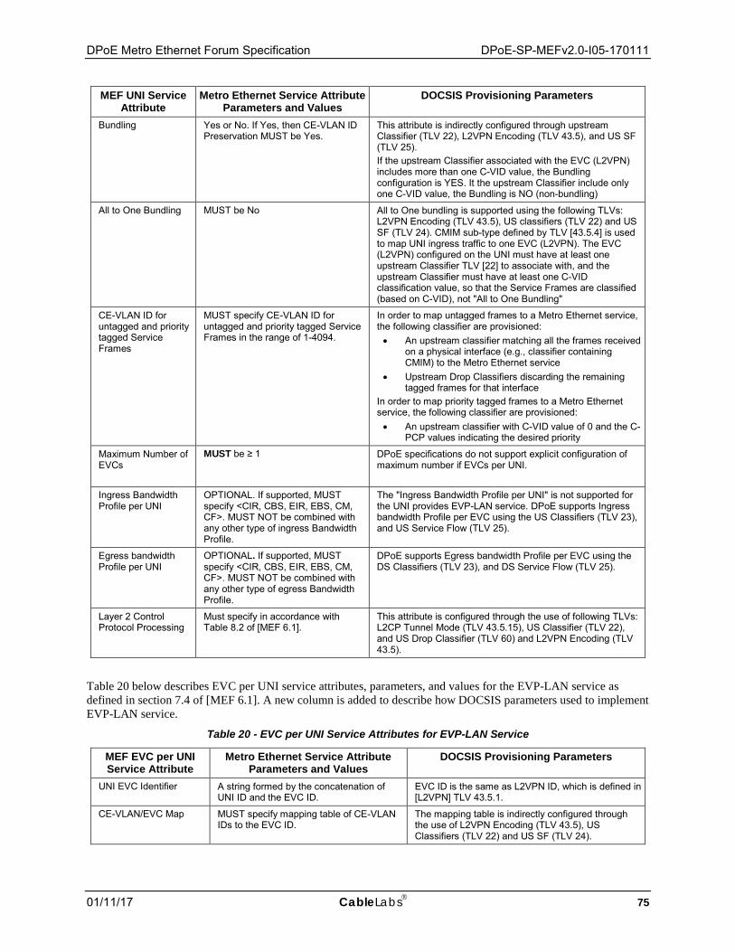
DPoE Metro Ethernet Forum Specification DPoE-SP-MEFv2.0-I05-170111
01/11/17 CableLabs 75
MEF UNI Service Attribute
Metro Ethernet Service Attribute Parameters and Values
DOCSIS Provisioning Parameters
Bundling Yes or No. If Yes, then CE-VLAN ID Preservation MUST be Yes.
This attribute is indirectly configured through upstream Classifier (TLV 22), L2VPN Encoding (TLV 43.5), and US SF (TLV 25). If the upstream Classifier associated with the EVC (L2VPN) includes more than one C-VID value, the Bundling configuration is YES. It the upstream Classifier include only one C-VID value, the Bundling is NO (non-bundling)
All to One Bundling MUST be No All to One bundling is supported using the following TLVs: L2VPN Encoding (TLV 43.5), US classifiers (TLV 22) and US SF (TLV 24). CMIM sub-type defined by TLV [43.5.4] is used to map UNI ingress traffic to one EVC (L2VPN). The EVC (L2VPN) configured on the UNI must have at least one upstream Classifier TLV [22] to associate with, and the upstream Classifier must have at least one C-VID classification value, so that the Service Frames are classified (based on C-VID), not "All to One Bundling"
CE-VLAN ID for untagged and priority tagged Service Frames
MUST specify CE-VLAN ID for untagged and priority tagged Service Frames in the range of 1-4094.
In order to map untagged frames to a Metro Ethernet service, the following classifier are provisioned: • An upstream classifier matching all the frames received
on a physical interface (e.g., classifier containing CMIM) to the Metro Ethernet service
• Upstream Drop Classifiers discarding the remaining tagged frames for that interface
In order to map priority tagged frames to a Metro Ethernet service, the following classifier are provisioned: • An upstream classifier with C-VID value of 0 and the C-
PCP values indicating the desired priority
Maximum Number of EVCs
MUST be ≥ 1 DPoE specifications do not support explicit configuration of maximum number if EVCs per UNI.
Ingress Bandwidth Profile per UNI
OPTIONAL. If supported, MUST specify <CIR, CBS, EIR, EBS, CM, CF>. MUST NOT be combined with any other type of ingress Bandwidth Profile.
The "Ingress Bandwidth Profile per UNI" is not supported for the UNI provides EVP-LAN service. DPoE supports Ingress bandwidth Profile per EVC using the US Classifiers (TLV 23), and US Service Flow (TLV 25).
Egress bandwidth Profile per UNI
OPTIONAL. If supported, MUST specify <CIR, CBS, EIR, EBS, CM, CF>. MUST NOT be combined with any other type of egress Bandwidth Profile.
DPoE supports Egress bandwidth Profile per EVC using the DS Classifiers (TLV 23), and DS Service Flow (TLV 25).
Layer 2 Control Protocol Processing
Must specify in accordance with Table 8.2 of [MEF 6.1].
This attribute is configured through the use of following TLVs: L2CP Tunnel Mode (TLV 43.5.15), US Classifier (TLV 22), and US Drop Classifier (TLV 60) and L2VPN Encoding (TLV 43.5).
Table 20 below describes EVC per UNI service attributes, parameters, and values for the EVP-LAN service as defined in section 7.4 of [MEF 6.1]. A new column is added to describe how DOCSIS parameters used to implement EVP-LAN service.
Table 20 - EVC per UNI Service Attributes for EVP-LAN Service
MEF EVC per UNI Service Attribute
Metro Ethernet Service Attribute Parameters and Values
DOCSIS Provisioning Parameters
UNI EVC Identifier A string formed by the concatenation of UNI ID and the EVC ID.
EVC ID is the same as L2VPN ID, which is defined in [L2VPN] TLV 43.5.1.
CE-VLAN/EVC Map MUST specify mapping table of CE-VLAN IDs to the EVC ID.
The mapping table is indirectly configured through the use of L2VPN Encoding (TLV 43.5), US Classifiers (TLV 22) and US SF (TLV 24).
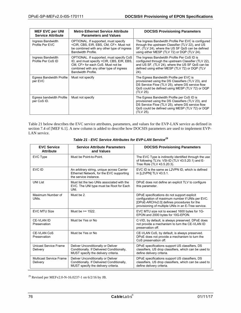
DPoE-SP-MEFv2.0-I05-170111 DOCSIS® Provisioning of EPON Specifications
76 CableLabs 01/11/17
MEF EVC per UNI Service Attribute
Metro Ethernet Service Attribute Parameters and Values
DOCSIS Provisioning Parameters
Ingress Bandwidth Profile Per EVC
OPTIONAL. If supported, must specify <CIR, CBS, EIR, EBS, CM, CF>. Must not be combined with any other type of ingress Bandwidth Profile.
The Ingress Bandwidth Profile Per EVC is configured through the upstream Classifier (TLV 22), and US SF, (TLV 24), where the US SF QoS can be defined using either MESP (TLV 72) or DQP (TLV 24).
Ingress Bandwidth Profile Per CoS ID
OPTIONAL. If supported, must specify CoS ID, and must specify <CIR, CBS, EIR, EBS, CM, CF> for each CoS. Must not be combined with any other type of ingress Bandwidth Profile.
The Ingress Bandwidth Profile Per CoS ID is configured through the upstream Classifier (TLV 22), and US SF, (TLV 24), where the US SF QoS can be defined using either MESP (TLV 72) or DQP (TLV 24).
Egress Bandwidth Profile per EVC
Must not specify The Egress Bandwidth Profile per EVC is provisioned using the DS Classifiers (TLV 23), and DS Service Flow (TLV 25), where DS service flow QoS could be defined using MESP (TLV 72) or DQP (TLV 25).
Egress bandwidth Profile per CoS ID.
Must not specify The Egress Bandwidth Profile per CoS ID is provisioned using the DS Classifiers (TLV 23), and DS Service Flow (TLV 25), where DS service flow QoS could be defined using MESP (TLV 72) or DQP (TLV 25).
Table 21 below describes the EVC service attributes, parameters, and values for the EVP-LAN service as defined in section 7.4 of [MEF 6.1]. A new column is added to describe how DOCSIS parameters are used to implement EVP-LAN service.
Table 21 - EVC Service Attributes for EVP-LAN Service29
EVC Service Attribute
Service Attribute Parameters and Values
DOCSIS Provisioning Parameters
EVC Type Must be Point-to-Point. The EVC Type is indirectly identified through the use of following TLVs: VSI-ID (TLV 43.5.20.1) and E-Tree Role (TLV 43.5.20.3).
EVC ID An arbitrary string, unique across Carrier Ethernet Network, for the EVC supporting the service instance.
EVC ID is the same as L2VPN ID, which is defined in [L2VPN] TLV 43.5.1.
UNI List Must list the two UNIs associated with the EVC. The UNI type must be Root for Each UNI.
DPoE does not define an explicit TLV to configure this parameter.
Maximum Number of UNIs.
Must be 2. DPoE specifications do not support explicit configuration of maximum number if UNIs per EVC. [DPoE-ARCHv2.0] defines procedures for the provisioning of multiple UNIs in an E-Tree service.
EVC MTU Size Must be >= 1522. EVC MTU size not to exceed 1600 bytes for 1G-EPON and 2000 bytes for 10G-EPON.
CE-VLAN ID Preservation
Must be Yes or No C-VID, by default, is always preserved. DPoE does not provide a mechanism to turn the CE-VLAN ID preservation off.
CE-VLAN CoS Preservation
Must be Yes or No CE-VLAN CoS, by default, is always preserved. DPoE does not provide a mechanism to turn the CoS preservation off.
Unicast Service Frame Delivery
Deliver Unconditionally or Deliver Conditionally. If Delivered Conditionally, MUST specify the delivery criteria.
DPoE specifications support US classifiers, DS classifiers, US drop classifiers, which can be used to define delivery criteria.
Multicast Service Frame Delivery
Deliver Unconditionally or Deliver Conditionally. If Delivered Conditionally, MUST specify the delivery criteria.
DPoE specifications support US classifiers, DS classifiers, US drop classifiers, which can be used to define delivery criteria.
29 Revised per MEFv2.0-N-16.0237-1 on 6/2/16 by JB.
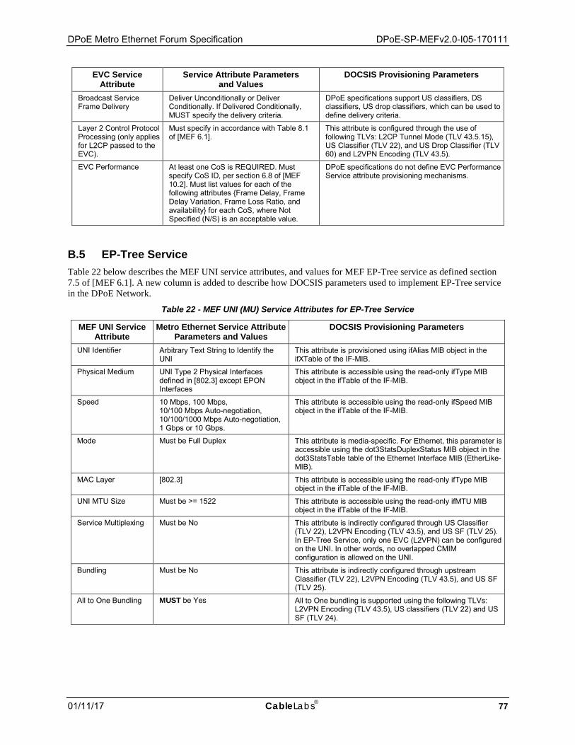
DPoE Metro Ethernet Forum Specification DPoE-SP-MEFv2.0-I05-170111
01/11/17 CableLabs 77
EVC Service Attribute
Service Attribute Parameters and Values
DOCSIS Provisioning Parameters
Broadcast Service Frame Delivery
Deliver Unconditionally or Deliver Conditionally. If Delivered Conditionally, MUST specify the delivery criteria.
DPoE specifications support US classifiers, DS classifiers, US drop classifiers, which can be used to define delivery criteria.
Layer 2 Control Protocol Processing (only applies for L2CP passed to the EVC).
Must specify in accordance with Table 8.1 of [MEF 6.1].
This attribute is configured through the use of following TLVs: L2CP Tunnel Mode (TLV 43.5.15), US Classifier (TLV 22), and US Drop Classifier (TLV 60) and L2VPN Encoding (TLV 43.5).
EVC Performance At least one CoS is REQUIRED. Must specify CoS ID, per section 6.8 of [MEF 10.2]. Must list values for each of the following attributes {Frame Delay, Frame Delay Variation, Frame Loss Ratio, and availability} for each CoS, where Not Specified (N/S) is an acceptable value.
DPoE specifications do not define EVC Performance Service attribute provisioning mechanisms.
B.5 EP-Tree Service Table 22 below describes the MEF UNI service attributes, and values for MEF EP-Tree service as defined section 7.5 of [MEF 6.1]. A new column is added to describe how DOCSIS parameters used to implement EP-Tree service in the DPoE Network.
Table 22 - MEF UNI (MU) Service Attributes for EP-Tree Service
MEF UNI Service Attribute
Metro Ethernet Service Attribute Parameters and Values
DOCSIS Provisioning Parameters
UNI Identifier Arbitrary Text String to Identify the UNI
This attribute is provisioned using ifAlias MIB object in the ifXTable of the IF-MIB.
Physical Medium UNI Type 2 Physical Interfaces defined in [802.3] except EPON Interfaces
This attribute is accessible using the read-only ifType MIB object in the ifTable of the IF-MIB.
Speed 10 Mbps, 100 Mbps, 10/100 Mbps Auto-negotiation, 10/100/1000 Mbps Auto-negotiation, 1 Gbps or 10 Gbps.
This attribute is accessible using the read-only ifSpeed MIB object in the ifTable of the IF-MIB.
Mode Must be Full Duplex This attribute is media-specific. For Ethernet, this parameter is accessible using the dot3StatsDuplexStatus MIB object in the dot3StatsTable table of the Ethernet Interface MIB (EtherLike-MIB).
MAC Layer [802.3] This attribute is accessible using the read-only ifType MIB object in the ifTable of the IF-MIB.
UNI MTU Size Must be >= 1522 This attribute is accessible using the read-only ifMTU MIB object in the ifTable of the IF-MIB.
Service Multiplexing Must be No This attribute is indirectly configured through US Classifier (TLV 22), L2VPN Encoding (TLV 43.5), and US SF (TLV 25). In EP-Tree Service, only one EVC (L2VPN) can be configured on the UNI. In other words, no overlapped CMIM configuration is allowed on the UNI.
Bundling Must be No This attribute is indirectly configured through upstream Classifier (TLV 22), L2VPN Encoding (TLV 43.5), and US SF (TLV 25).
All to One Bundling MUST be Yes All to One bundling is supported using the following TLVs: L2VPN Encoding (TLV 43.5), US classifiers (TLV 22) and US SF (TLV 24).
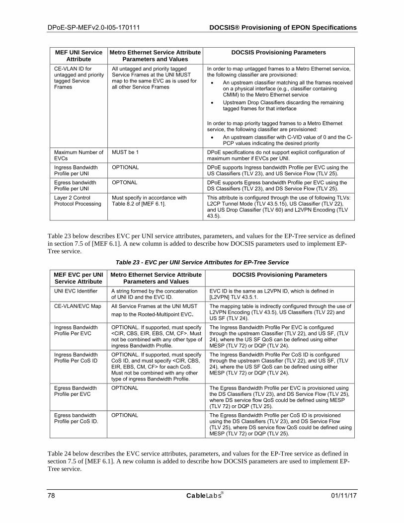
DPoE-SP-MEFv2.0-I05-170111 DOCSIS® Provisioning of EPON Specifications
78 CableLabs 01/11/17
MEF UNI Service Attribute
Metro Ethernet Service Attribute Parameters and Values
DOCSIS Provisioning Parameters
CE-VLAN ID for untagged and priority tagged Service Frames
All untagged and priority tagged Service Frames at the UNI MUST map to the same EVC as is used for all other Service Frames
In order to map untagged frames to a Metro Ethernet service, the following classifier are provisioned: • An upstream classifier matching all the frames received
on a physical interface (e.g., classifier containing CMIM) to the Metro Ethernet service
• Upstream Drop Classifiers discarding the remaining tagged frames for that interface
In order to map priority tagged frames to a Metro Ethernet service, the following classifier are provisioned: • An upstream classifier with C-VID value of 0 and the C-
PCP values indicating the desired priority
Maximum Number of EVCs
MUST be 1 DPoE specifications do not support explicit configuration of maximum number if EVCs per UNI.
Ingress Bandwidth Profile per UNI
OPTIONAL DPoE supports Ingress bandwidth Profile per EVC using the US Classifiers (TLV 23), and US Service Flow (TLV 25).
Egress bandwidth Profile per UNI
OPTONAL DPoE supports Egress bandwidth Profile per EVC using the DS Classifiers (TLV 23), and DS Service Flow (TLV 25).
Layer 2 Control Protocol Processing
Must specify in accordance with Table 8.2 of [MEF 6.1].
This attribute is configured through the use of following TLVs: L2CP Tunnel Mode (TLV 43.5.15), US Classifier (TLV 22), and US Drop Classifier (TLV 60) and L2VPN Encoding (TLV 43.5).
Table 23 below describes EVC per UNI service attributes, parameters, and values for the EP-Tree service as defined in section 7.5 of [MEF 6.1]. A new column is added to describe how DOCSIS parameters used to implement EP-Tree service.
Table 23 - EVC per UNI Service Attributes for EP-Tree Service
MEF EVC per UNI Service Attribute
Metro Ethernet Service Attribute Parameters and Values
DOCSIS Provisioning Parameters
UNI EVC Identifier A string formed by the concatenation of UNI ID and the EVC ID.
EVC ID is the same as L2VPN ID, which is defined in [L2VPN] TLV 43.5.1.
CE-VLAN/EVC Map All Service Frames at the UNI MUST map to the Rooted-Multipoint EVC.
The mapping table is indirectly configured through the use of L2VPN Encoding (TLV 43.5), US Classifiers (TLV 22) and US SF (TLV 24).
Ingress Bandwidth Profile Per EVC
OPTIONAL. If supported, must specify <CIR, CBS, EIR, EBS, CM, CF>. Must not be combined with any other type of ingress Bandwidth Profile.
The Ingress Bandwidth Profile Per EVC is configured through the upstream Classifier (TLV 22), and US SF, (TLV 24), where the US SF QoS can be defined using either MESP (TLV 72) or DQP (TLV 24).
Ingress Bandwidth Profile Per CoS ID
OPTIONAL. If supported, must specify CoS ID, and must specify <CIR, CBS, EIR, EBS, CM, CF> for each CoS. Must not be combined with any other type of ingress Bandwidth Profile.
The Ingress Bandwidth Profile Per CoS ID is configured through the upstream Classifier (TLV 22), and US SF, (TLV 24), where the US SF QoS can be defined using either MESP (TLV 72) or DQP (TLV 24).
Egress Bandwidth Profile per EVC
OPTIONAL The Egress Bandwidth Profile per EVC is provisioned using the DS Classifiers (TLV 23), and DS Service Flow (TLV 25), where DS service flow QoS could be defined using MESP (TLV 72) or DQP (TLV 25).
Egress bandwidth Profile per CoS ID.
OPTIONAL The Egress Bandwidth Profile per CoS ID is provisioned using the DS Classifiers (TLV 23), and DS Service Flow (TLV 25), where DS service flow QoS could be defined using MESP (TLV 72) or DQP (TLV 25).
Table 24 below describes the EVC service attributes, parameters, and values for the EP-Tree service as defined in section 7.5 of [MEF 6.1]. A new column is added to describe how DOCSIS parameters are used to implement EP-Tree service.

DPoE Metro Ethernet Forum Specification DPoE-SP-MEFv2.0-I05-170111
01/11/17 CableLabs 79
Table 24 - EVC Service Attributes for EP-Tree Service30
EVC Service Attribute
Service Attribute Parameters and Values
DOCSIS Provisioning Parameters
EVC Type MUST be Rooted Multipoint The EVC Type is indirectly identified through the use of following TLVs: VSI-ID (TLV 43.5.20.1) and E-Tree Role (TLV 43.5.20.3).
EVC ID An arbitrary string, unique across Carrier Ethernet Network, for the EVC supporting the service instance.
EVC ID is the same as L2VPN ID, which is defined in [L2VPN] TLV 43.5.1.
UNI List MUST list the UNIs associated with the EVC. The UNI Type for at least 1 UNI MUST be Root. All UNIs that are not UNI Type Root MUST be UNI Type Leaf.
DPoE does not define an explicit TLV to configure this attribute.
Maximum Number of UNIs.
MUST be ≥ 2 DPoE specifications do not support explicit configuration of maximum number if UNIs per EVC. [DPoE-ARCHv2.0] defines procedures for the provisioning of multiple UNIs in an E-Tree service.
EVC MTU Size Must be >= 1522. EVC MTU size not to exceed 1600 bytes for 1G-EPON and 2000 bytes for 10G-EPON.
CE-VLAN ID Preservation
Must be Yes C-VID, by default, is always preserved. DPoE does not provide a mechanism to turn the CE-VLAN ID preservation off.
CE-VLAN CoS Preservation
Must be Yes CE-VLAN CoS, by default, is always preserved. DPoE does not provide a mechanism to turn the CoS preservation off.
Unicast Service Frame Delivery
Deliver Unconditionally or Deliver Conditionally. If Delivered Conditionally, MUST specify the delivery criteria.
DPoE specifications support US classifiers, DS classifiers, US drop classifiers, which can be used to define delivery criteria
Multicast Service Frame Delivery
Deliver Unconditionally or Deliver Conditionally. If Delivered Conditionally, MUST specify the delivery criteria.
DPoE specifications support US classifiers, DS classifiers, US drop classifiers, which can be used to define delivery criteria
Broadcast Service Frame Delivery
Deliver Unconditionally or Deliver Conditionally. If Delivered Conditionally, MUST specify the delivery criteria.
DPoE specifications support US classifiers, DS classifiers, US drop classifiers, which can be used to define delivery criteria
Layer 2 Control Protocol Processing (only applies for L2CP passed to the EVC).
Must specify in accordance with Table 8.1 of [MEF 6.1].
This attribute is configured through the use of following TLVs: L2CP Tunnel Mode (TLV 43.5.15), US Classifier (TLV 22), and US Drop Classifier (TLV 60) and L2VPN Encoding (TLV 43.5).
EVC Performance At least one CoS is REQUIRED. Must specify CoS ID, per section 6.8 of [MEF 10.2]. Must list values for each of the following attributes {Frame Delay, Frame Delay Variation, Frame Loss Ratio, and availability} for each CoS, where Not Specified (N/S) is an acceptable value.
DPoE specifications do not define EVC Performance Service attribute provisioning mechanisms.
B.6 EVP-Tree Service Table 25 below describes the MEF UNI service attributes, and values for MEF EVP-Tree service as defined in section 7.6 of [MEF 6.1]. A new column is added to describe how DOCSIS parameters used to implement EVP-Tree service in the DPoE Network.
30 Revised per MEFv2.0-N-16.0237-1 on 6/2/16 by JB.
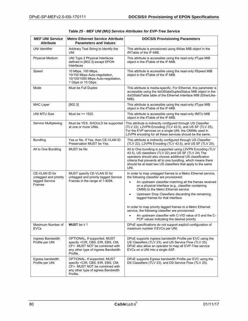
DPoE-SP-MEFv2.0-I05-170111 DOCSIS® Provisioning of EPON Specifications
80 CableLabs 01/11/17
Table 25 - MEF UNI (MU) Service Attributes for EVP-Tree Service
MEF UNI Service Attribute
Metro Ethernet Service Attribute Parameters and Values
DOCSIS Provisioning Parameters
UNI Identifier Arbitrary Text String to Identify the UNI
This attribute is provisioned using ifAlias MIB object in the ifXTable of the IF-MIB.
Physical Medium UNI Type 2 Physical Interfaces defined in [802.3] except EPON Interfaces
This attribute is accessible using the read-only ifType MIB object in the ifTable of the IF-MIB.
Speed 10 Mbps, 100 Mbps, 10/100 Mbps Auto-negotiation, 10/100/1000 Mbps Auto-negotiation, 1 Gbps or 10 Gbps.
This attribute is accessible using the read-only ifSpeed MIB object in the ifTable of the IF-MIB.
Mode Must be Full Duplex This attribute is media-specific. For Ethernet, this parameter is accessible using the dot3StatsDuplexStatus MIB object in the dot3StatsTable table of the Ethernet Interface MIB (EtherLike-MIB).
MAC Layer [802.3] This attribute is accessible using the read-only ifType MIB object in the ifTable of the IF-MIB.
UNI MTU Size Must be >= 1522 This attribute is accessible using the read-only ifMTU MIB object in the ifTable of the IF-MIB.
Service Multiplexing Must be YES. SHOULD be supported at one or more UNIs.
This attribute is indirectly configured through US Classifier (TLV 22), L2VPN Encoding (TLV 43.5), and US SF (TLV 25). For the EVP services on a single UNI, the CMIMs used in L2VPN encoding for all these services should be the same.
Bundling Yes or No. If Yes, then CE-VLAN ID Preservation MUST be Yes.
This attribute is indirectly configured through US Classifier (TLV 22), L2VPN Encoding (TLV 43.5), and US SF (TLV 25).
All to One Bundling MUST be No All to One bundling is supported using L2VPN Encoding (TLV 43.5), US classifiers (TLV 22) and US SF (TLV 24) The operators should also choose additional US classification criteria that prevents all to one bundling, which means there should be at least two US classifiers that apply to the same UNI.
CE-VLAN ID for untagged and priority tagged Service Frames
MUST specify CE-VLAN ID for untagged and priority tagged Service Frames in the range of 1-4094.
In order to map untagged frames to a Metro Ethernet service, the following classifier are provisioned: • An upstream classifier matching all the frames received
on a physical interface (e.g., classifier containing CMIM) to the Metro Ethernet service
• Upstream Drop Classifiers discarding the remaining tagged frames for that interface
In order to map priority tagged frames to a Metro Ethernet service, the following classifier are provisioned: • An upstream classifier with C-VID value of 0 and the C-
PCP values indicating the desired priority
Maximum Number of EVCs
MUST be ≥ 1 DPoE specifications do not support explicit configuration of maximum number if EVCs per UNI.
Ingress Bandwidth Profile per UNI
OPTIONAL. If supported, MUST specify <CIR, CBS, EIR, EBS, CM, CF>. MUST NOT be combined with any other type of ingress Bandwidth Profile.
DPoE supports Ingress bandwidth Profile per EVC using the US Classifiers (TLV 23), and US Service Flow (TLV 25). DPoE also allow an operator to map all EVP-Tree service EVCs on a UNI into a single ASF.
Egress bandwidth Profile per UNI
OPTIONAL. If supported, MUST specify <CIR, CBS, EIR, EBS, CM, CF>. MUST NOT be combined with any other type of egress Bandwidth Profile.
DPoE supports Egress bandwidth Profile per EVC using the DS Classifiers (TLV 23), and DS Service Flow (TLV 25).
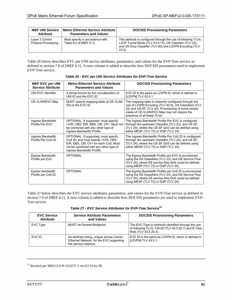
DPoE Metro Ethernet Forum Specification DPoE-SP-MEFv2.0-I05-170111
01/11/17 CableLabs 81
MEF UNI Service Attribute
Metro Ethernet Service Attribute Parameters and Values
DOCSIS Provisioning Parameters
Layer 2 Control Protocol Processing
Must specify in accordance with Table 8.2 of [MEF 6.1].
This attribute is configured through the use of following TLVs: L2CP Tunnel Mode (TLV 43.5.15), US Classifier (TLV 22), and US Drop Classifier (TLV 60) and L2VPN Encoding (TLV 43.5).
Table 26 below describes EVC per UNI service attributes, parameters, and values for the EVP-Tree service as defined in section 7.6 of [MEF 6.1]. A new column is added to describe how DOCSIS parameters used to implement EVP-Tree service.
Table 26 - EVC per UNI Service Attributes for EVP-Tree Service
MEF EVC per UNI Service Attribute
Metro Ethernet Service Attribute Parameters and Values
DOCSIS Provisioning Parameters
UNI EVC Identifier A string formed by the concatenation of UNI ID and the EVC ID.
EVC ID is the same as L2VPN ID, which is defined in [L2VPN] TLV 43.5.1.
CE-VLAN/EVC Map MUST specify mapping table of CE-VLAN IDs to the EVC ID.
The mapping table is indirectly configured through the use of L2VPN Encoding (TLV 43.5), US Classifiers (TLV 22) and US SF (TLV 24). Provisioning of some simple cases of CE-VLAN/EVC Map may not require the presence of all these TLVs.
Ingress Bandwidth Profile Per EVC
OPTIONAL. If supported, must specify <CIR, CBS, EIR, EBS, CM, CF>. Must not be combined with any other type of ingress Bandwidth Profile.
The Ingress Bandwidth Profile Per EVC is configured through the upstream Classifier (TLV 22), and US SF, (TLV 24), where the US SF QoS can be defined using either MESP (TLV 72) or DQP (TLV 24).
Ingress Bandwidth Profile Per CoS ID
OPTIONAL. If supported, must specify CoS ID, and must specify <CIR, CBS, EIR, EBS, CM, CF> for each CoS. Must not be combined with any other type of ingress Bandwidth Profile.
The Ingress Bandwidth Profile Per CoS ID is configured through the upstream Classifier (TLV 22), and US SF, (TLV 24), where the US SF QoS can be defined using either MESP (TLV 72) or DQP (TLV 24).
Egress Bandwidth Profile per EVC
OPTIONAL The Egress Bandwidth Profile per EVC is provisioned using the DS Classifiers (TLV 23), and DS Service Flow (TLV 25), where DS service flow QoS could be defined using MESP (TLV 72) or DQP (TLV 25).
Egress bandwidth Profile per CoS ID.
OPTIONAL The Egress Bandwidth Profile per CoS ID is provisioned using the DS Classifiers (TLV 23), and DS Service Flow (TLV 25), where DS service flow QoS could be defined using MESP (TLV 72) or DQP (TLV 25).
Table 27 below describes the EVC service attributes, parameters, and values for the EVP-Tree service as defined in section 7.6 of [MEF 6.1]. A new column is added to describe how DOCSIS parameters are used to implement EVP-Tree service.
Table 27 - EVC Service Attributes for EVP-Tree Service31
EVC Service Attribute
Service Attribute Parameters and Values
DOCSIS Provisioning Parameters
EVC Type MUST be Rooted-Multipoint The EVC Type is indirectly identified through the use of following TLVs: VSI-ID (TLV 43.5.20.1) and E-Tree Role (TLV 43.5.20.3).
EVC ID An arbitrary string, unique across Carrier Ethernet Network, for the EVC supporting the service instance.
EVC ID is the same as L2VPN ID, which is defined in [L2VPN] TLV 43.5.1.
31 Revised per MEFv2.0-N-16.0237-1 on 6/2/16 by JB.
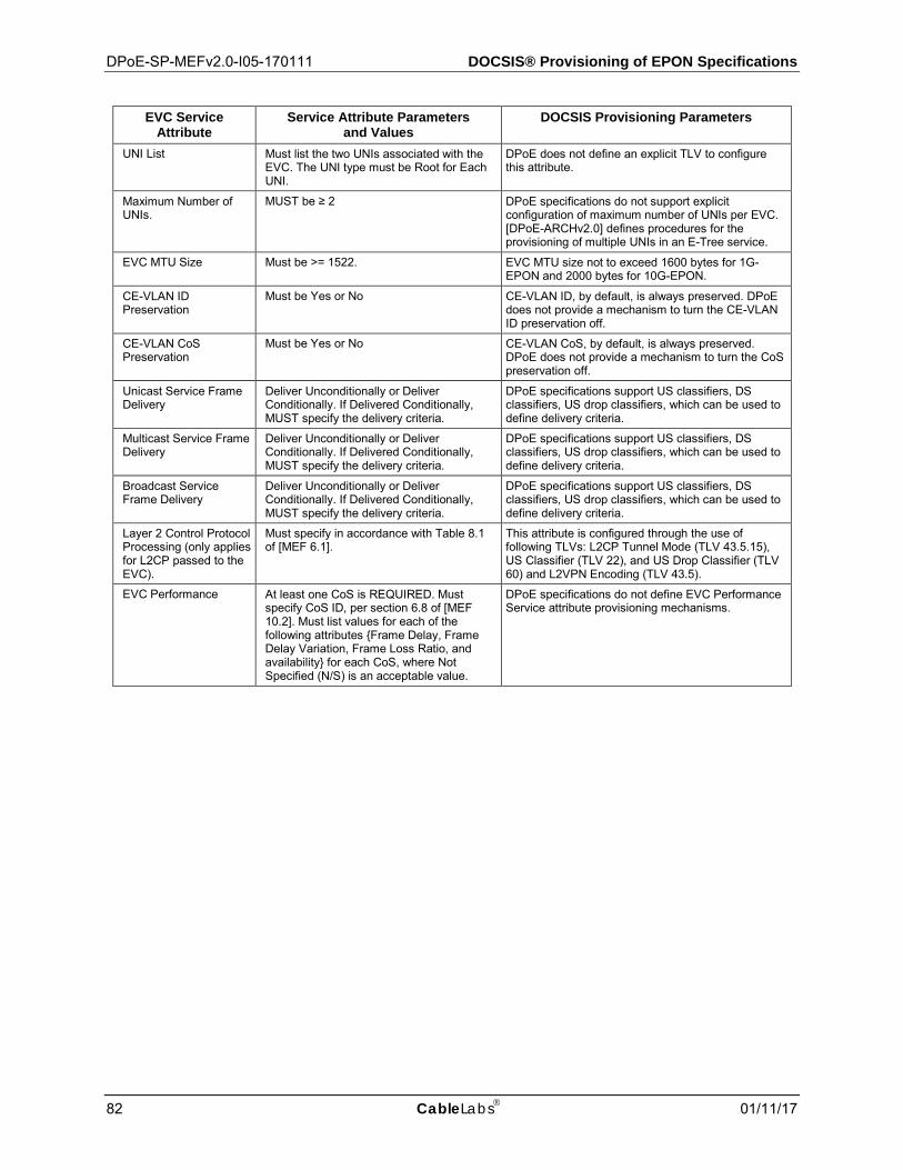
DPoE-SP-MEFv2.0-I05-170111 DOCSIS® Provisioning of EPON Specifications
82 CableLabs 01/11/17
EVC Service Attribute
Service Attribute Parameters and Values
DOCSIS Provisioning Parameters
UNI List Must list the two UNIs associated with the EVC. The UNI type must be Root for Each UNI.
DPoE does not define an explicit TLV to configure this attribute.
Maximum Number of UNIs.
MUST be ≥ 2 DPoE specifications do not support explicit configuration of maximum number of UNIs per EVC. [DPoE-ARCHv2.0] defines procedures for the provisioning of multiple UNIs in an E-Tree service.
EVC MTU Size Must be >= 1522. EVC MTU size not to exceed 1600 bytes for 1G-EPON and 2000 bytes for 10G-EPON.
CE-VLAN ID Preservation
Must be Yes or No CE-VLAN ID, by default, is always preserved. DPoE does not provide a mechanism to turn the CE-VLAN ID preservation off.
CE-VLAN CoS Preservation
Must be Yes or No CE-VLAN CoS, by default, is always preserved. DPoE does not provide a mechanism to turn the CoS preservation off.
Unicast Service Frame Delivery
Deliver Unconditionally or Deliver Conditionally. If Delivered Conditionally, MUST specify the delivery criteria.
DPoE specifications support US classifiers, DS classifiers, US drop classifiers, which can be used to define delivery criteria.
Multicast Service Frame Delivery
Deliver Unconditionally or Deliver Conditionally. If Delivered Conditionally, MUST specify the delivery criteria.
DPoE specifications support US classifiers, DS classifiers, US drop classifiers, which can be used to define delivery criteria.
Broadcast Service Frame Delivery
Deliver Unconditionally or Deliver Conditionally. If Delivered Conditionally, MUST specify the delivery criteria.
DPoE specifications support US classifiers, DS classifiers, US drop classifiers, which can be used to define delivery criteria.
Layer 2 Control Protocol Processing (only applies for L2CP passed to the EVC).
Must specify in accordance with Table 8.1 of [MEF 6.1].
This attribute is configured through the use of following TLVs: L2CP Tunnel Mode (TLV 43.5.15), US Classifier (TLV 22), and US Drop Classifier (TLV 60) and L2VPN Encoding (TLV 43.5).
EVC Performance At least one CoS is REQUIRED. Must specify CoS ID, per section 6.8 of [MEF 10.2]. Must list values for each of the following attributes {Frame Delay, Frame Delay Variation, Frame Loss Ratio, and availability} for each CoS, where Not Specified (N/S) is an acceptable value.
DPoE specifications do not define EVC Performance Service attribute provisioning mechanisms.
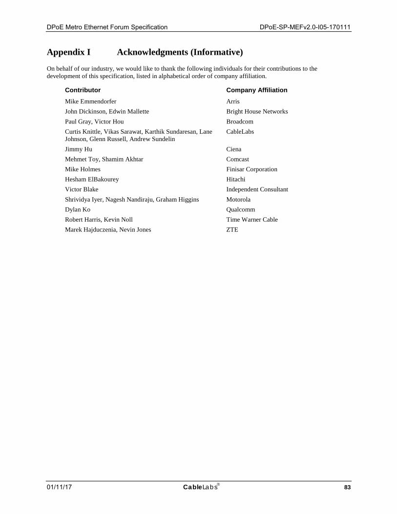
DPoE Metro Ethernet Forum Specification DPoE-SP-MEFv2.0-I05-170111
01/11/17 CableLabs 83
Appendix I Acknowledgments (Informative)
On behalf of our industry, we would like to thank the following individuals for their contributions to the development of this specification, listed in alphabetical order of company affiliation.
Contributor Company Affiliation Mike Emmendorfer Arris John Dickinson, Edwin Mallette Bright House Networks Paul Gray, Victor Hou Broadcom Curtis Knittle, Vikas Sarawat, Karthik Sundaresan, Lane Johnson, Glenn Russell, Andrew Sundelin
CableLabs
Jimmy Hu Ciena Mehmet Toy, Shamim Akhtar Comcast Mike Holmes Finisar Corporation Hesham ElBakourey Hitachi Victor Blake Independent Consultant Shrividya Iyer, Nagesh Nandiraju, Graham Higgins Motorola Dylan Ko Qualcomm Robert Harris, Kevin Noll Time Warner Cable Marek Hajduczenia, Nevin Jones ZTE
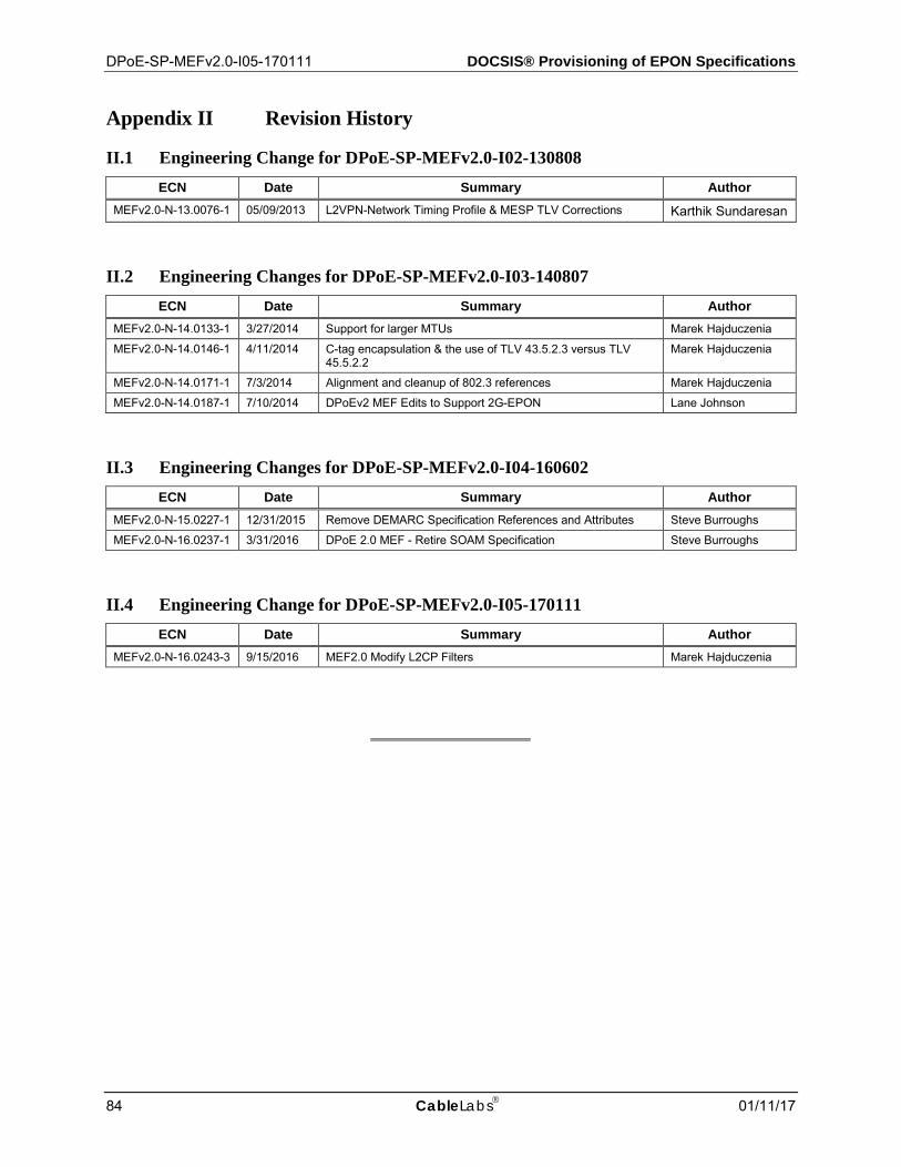
DPoE-SP-MEFv2.0-I05-170111 DOCSIS® Provisioning of EPON Specifications
84 CableLabs 01/11/17
Appendix II Revision History
II.1 Engineering Change for DPoE-SP-MEFv2.0-I02-130808 ECN Date Summary Author
MEFv2.0-N-13.0076-1 05/09/2013 L2VPN-Network Timing Profile & MESP TLV Corrections Karthik Sundaresan
II.2 Engineering Changes for DPoE-SP-MEFv2.0-I03-140807 ECN Date Summary Author
MEFv2.0-N-14.0133-1 3/27/2014 Support for larger MTUs Marek Hajduczenia MEFv2.0-N-14.0146-1 4/11/2014 C-tag encapsulation & the use of TLV 43.5.2.3 versus TLV
45.5.2.2 Marek Hajduczenia
MEFv2.0-N-14.0171-1 7/3/2014 Alignment and cleanup of 802.3 references Marek Hajduczenia MEFv2.0-N-14.0187-1 7/10/2014 DPoEv2 MEF Edits to Support 2G-EPON Lane Johnson
II.3 Engineering Changes for DPoE-SP-MEFv2.0-I04-160602 ECN Date Summary Author
MEFv2.0-N-15.0227-1 12/31/2015 Remove DEMARC Specification References and Attributes Steve Burroughs MEFv2.0-N-16.0237-1 3/31/2016 DPoE 2.0 MEF - Retire SOAM Specification Steve Burroughs
II.4 Engineering Change for DPoE-SP-MEFv2.0-I05-170111 ECN Date Summary Author
MEFv2.0-N-16.0243-3 9/15/2016 MEF2.0 Modify L2CP Filters Marek Hajduczenia