Embed Size (px)
Citation preview
Coal beneficiation
Dr Ian Reid
CCC/278
June 2017
© IEA Clean Coal Centre
IEA Clean Coal Centre – Coal beneficiation 2
Coal beneficiation Author: Dr Ian Reid
IEACCC Ref: CCC/278
ISBN: 978–92–9029–600-3
Copyright: © IEA Clean Coal Centre
Published Date: June 2017
IEA Clean Coal Centre Apsley House Third Floor 176 Upper Richmond Road London SW15 2SH United Kingdom
Telephone: +44(0)20 3095 3870
www.iea-coal.org

IEA Clean Coal Centre – Coal beneficiation 3
Preface
This report has been produced by IEA Clean Coal Centre and is based on a survey and analysis of published literature, and on information gathered in discussions with interested organisations and individuals. Their assistance is gratefully acknowledged. It should be understood that the views expressed in this report are our own, and are not necessarily shared by those who supplied the information, nor by our member countries.
IEA Clean Coal Centre is an organisation set up under the auspices of the International Energy Agency (IEA) which was itself founded in 1974 by member countries of the Organisation for Economic Co-operation and Development (OECD). The purpose of the IEA is to explore means by which countries interested in minimising their dependence on imported oil can co-operate. In the field of Research, Development and Demonstration over fifty individual projects have been established in partnership between member countries of the IEA.
IEA Clean Coal Centre began in 1975 and has contracting parties and sponsors from: Australia, China, the European Commission, Germany, India, Italy, Japan, Poland, Russia, South Africa, Thailand, the UAE, the UK and the USA. The Service provides information and assessments on all aspects of coal from supply and transport, through markets and end-use technologies, to environmental issues and waste utilisation.
Neither IEA Clean Coal Centre nor any of its employees nor any supporting country or organisation, nor any employee or contractor of IEA Clean Coal Centre, makes any warranty, expressed or implied, or assumes any legal liability or responsibility for the accuracy, completeness or usefulness of any information, apparatus, product or process disclosed, or represents that its use would not infringe privately-owned rights.
IEA Clean Coal Centre – Coal beneficiation 4
Abstract
Up till now the power industry has largely met the demand to increase efficiency and reduce emissions by
improving boiler technology and post combustion emission treatment. However, feedstock quality is a key
element to improve coal power plant performance. The preparation of coal to remove inert matter and
reduce contaminants can benefit every aspect of power plant operation. This report reviews a broad range
of technical developments in coal beneficiation covering conventional, physical dense-media and dry coal
treatment, upgrading technologies using thermal, chemical and bio-oxidation, coal blending, and
applications for the use of ultrafine coal and waste streams.
Lignite power generation normally utilises raw feedstock resulting in significant energy and reliability
penalties; the report discusses energy efficient technologies that reduce moisture and ash levels.
The direct injection coal engine (DICE) may have the potential to compete with diesel fuel as a source of
compact flexible power generation, offering a rapid response to complement intermittent renewable
energy generation. Suitable coal sources and preparation methods are discussed for the production of
micronised refined carbon (MRC) fuels, with specific formulations that overcome issues associated with
coal water slurry fuels.
IEA Clean Coal Centre – Coal beneficiation 5
Acronyms and abbreviations ADMFB air dense-media fluidised bed
ARA Amsterdam-Rotterdam-Antwerp
AUSC advanced ultrasupercritical steam system
CCS(g) Clean Combustion System gasifier
CGA coal grain analysis
CIF cost insurance and freight
CPP coal preparation plants
CSIRO Commonwealth Scientific and Industrial Research Organisation (Australia)
CWS coal water slurry
CWF coal water fuel
DICE direct injection carbon engine
DMC dense-media cyclone
D&R drain and rinse
DSI dry sorbent injection
US$/GJ dollars per Giga Joule (note: 1 GJ = 0.948 million Btu = 9.48 therm)
Ep particle efficiency in coal separation
ESP electrostatic precipitator
FGD flue gas desulphurisation
GCV gross calorific value
GHG greenhouse gas
HELE high efficiency low emission
HHS hydrophobic-hydrophilic 2-liquid separation
IEA International Energy Agency
LNG liquefied natural gas
mPa.s millipascal-second (viscosity)
MPa megapascal, 1 MPa = 10 bar pressure
MRC micronised refined carbon
Mtce million tonnes carbon equivalent
NaOH sodium hydroxide (caustic soda)
NGM near gravity material
NMP N-methyl-2-pyrrolidone
OECD Organisation for Economic Co-operation and Development
PRB Powder River Basin (USA)
Ƿ Density
rpm revolutions per minute
ROM run-of-mine coal (raw supply)
REE rare earth elements
SBC screen-bowl centrifuge
SC supercritical
SCR selective catalytic reduction (NOx)
SNCR selective non-catalytic reduction (NOx)
SSC screen-scroll centrifuge
SG specific gravity
t/h tonnes per hour
UCC ultra-clean coal
UHV useful heat value
USC ultrasupercritical
WHT internal waste heat utilisation
IEA Clean Coal Centre – Coal beneficiation 6
Contents Preface 3
Abstract 4
Acronyms and abbreviations 5
Contents 6
List of Figures 7
List of Tables 8
1 Introduction 9
2 Projected coal demand 2016 to 2040: implications for new coal preparation facilities 12
3 Coal blending and feedstock additives 15 3.1 Coal blending 15 3.2 Coal feedstock additives 15
4 Wet and dry coal physical separation technologies 17 4.1 Coal washery methods 19
4.1.1 Coal comminution (crushing) and sizing 22 4.1.2 Coarse coal cleaning – dense-media 24 4.1.3 Intermediate coal cleaning – dense-media cyclone 24 4.1.4 Fine coal treatment – spirals 25 4.1.5 Fine or ultrafine coal circuit – flotation and agglomeration 26 4.1.6 Dewatering 28
4.2 Dry coal beneficiation 30 4.2.1 Air jigs and FGX Dry Separator 32 4.2.2 X-ray sorting 35
4.3 Hydrophobic hydrophilic 2-liquid separation (HHS) for ultrafine coal slurries 36 4.4 Coal preparation in India 37 4.5 Coal washery costs 37 4.6 Overall trends in physical separation methods 38
5 Thermal coal beneficiation (coal refining) 40 5.1 Thermally stabilised coal 40 5.2 Thermal cracking and fractionation 42 5.3 Beneficiation module of a retrofit hybrid gasifier 42 5.4 Turbulent air and hydrothermal drying 45
6 Chemical digestion and bio-oxidation 46 6.1 Chemical digestion and leaching 46
6.1.1 New developments in chemical leaching 48 6.2 Bio-desulphurisation 49 6.3 Chemical and bio-desulphurisation costs 51 6.4 Overview of chemical and biological methods 51
7 Lignite drying and demineralisation 52 7.1 Drying technologies 52
8 Micronised fuel for a direct injection carbon engine (DICE) 55 8.1 Suitable coal resources for micronised refined carbon fuel 56
8.1.1 Coal grain analysis method 57 8.2 Preparation of MRC fuel 57
8.2.1 Preparation of MRC from ROM coal and tailings – the Jameson Cell 59 8.2.2 Viscosity modification – MRC fuel transport, storage and atomisation 60 8.2.3 Abrasion and erosion 61
8.3 MRC fuel summary 62
9 Conclusions 63
10 References 66
11 Appendix: Internationally traded beneficiated coal specification 74
IEA Clean Coal Centre – Coal beneficiation 7
List of Figures Figure 1 IEA near-term global coal demand by region (historical and forecast) for the period 2000-2020 14
Figure 2 Flowsheet for a typical US coal preparation plant 20
Figure 3 Example of a heavy media-based coal washery, Mugla, Turkey 21
Figure 4 DM intermediate coal cyclone arranged at a 15° angle 25
Figure 5 Spiral concentrator schematic and a compound Krebs 2-stage spiral bank fitted 25
Figure 6 Simplified schematic of a mechanically agitated cell and image of a flotation cell fitted with a Wemco drive 27
Figure 7 Sub325 Centrifuge to dewater fine coal 29
Figure 8 Adapted Stomp coal air jig 33
Figure 9 The FGX coarse coal separator, simplified process flow diagram showing 2-stage dust collection and a photograph of a 240 t/h FGX 24A in South Africa 34
Figure 10 X-ray ore sorting device DriJet™ 35
Figure 11 Hydrophobic-hydrophilic separation process 36
Figure 12 Clean Coal Inc Pristine-M™ thermal coal cleaning process module 41
Figure 13 Schematic of the coal preparation stage as a gasifier retrofit to a PCC 43
Figure 14 Flow chart of a multistage chemical coal cleaning system 47
Figure 15 Process flowsheet of a plant for coal bio-depyritisation 50
Figure 16 Coal processed to form an ultrafine suspension of coal particles in water for firing in a large capacity diesel engine 56
Figure 17 Comparison of the processing cost as a function of ash content (dry basis) dependent on ROM coal beneficiation techniques 58
Figure 18 Jameson Cell, a high-intensity froth flotation cell for the separation of ultrafine coal, with detail of the downcomer air entrainment device 59

IEA Clean Coal Centre – Coal beneficiation 8
List of Tables Table 1 Coal demand by region 2013-2040 under the New Policies Scenario, Mtce 13
Table 2 Typical ash component analysis found in Internationally-traded coal, averaged data 17
Table 3 Benefits of coal washing – replacing ROM coal (41% ash) with prepared coal (30% ash) 18
Table 4 Current technologies in coal preparation plants 19
Table 5 Separation results obtained using a compound spiral system fitted with slurry repulping boxes 26
Table 6 New coking coal washeries 37
Table 7 Cost of coal beneficiation 38
Table 8 Pristine M typical coal upgrade performance 41
Table 9 Key features of WTA and DryFining™ fluidised bed lignite dryers 53
Table A1 Coal specification ARA 74

Introduction
IEA Clean Coal Centre – Coal beneficiation 9
1 Introduction
The worldwide coal power industry must rise to the challenge imposed by more stringent environmental
regulations; typically, higher performance targets are achieved by the adoption of high efficiency low
emission (HELE) technologies that raise plant efficiency and lower pollutant emissions. Internationally
traded coals are prepared to achieve a uniform coal standard; substitution by inexpensive, minimally
prepared high ash indigenous coals impairs power station performance, affecting every aspect of an
installation. The quality of the coal directly influences the selection and optimal implementation of the
latest high performance boiler technologies. The impact of coal properties is now of greater significance
due to the introduction of carbon dioxide emission targets.
Overall the energy content of coal resources is gradually declining. The average gross calorific value (GCV)
of coal consumed in the USA has steadily fallen from 28 MJ/kg to 20 MJ/kg over the last 50 years; most USA
coal supplies are now of low-sulphur subbituminous grade mined from the Powder River Basin, Wyoming.
Similarly, in India the GCV of coal has fallen from 24.7 to 14.7 MJ/kg in the same period (Mills, 2016). The
reduction in coal quality impacts upon power station performance inhibiting efforts to maximise energy
efficiency.
In the coal mining industry ‘beneficiation’ is any process which removes minerals from coal, to produce a
higher-grade product (concentrate) and a waste stream (tailings). Power stations that use beneficiated
coals can obtain practical, environmental and economic benefits over those plants that use minimally
processed or sized coal. A cleaner, more concentrated fuel will lead to improved boiler operation by the
reduction of ash formation in the boiler which in turn minimises fouling, ash handling and disposal. High
ash and water content in coal lowers the overall plant efficiency, necessitating a larger, more expensive
installation with increased fuel handling and consumption. Beneficiation processes partially remove the
pollutant precursors that lead to particulates, sulphur and mercury; beneficiation may ultimately return
significant cost savings in emissions control equipment. A prepared coal typically lowers greenhouse gas
emissions by about 5% when compared to the combustion of untreated, run-of-mine (ROM) coal.
Economically, significant cost savings are obtained from the improved coal handling and transport of
beneficiated coal (Zamuda, 2007).
However, the industry continues the commercial use of indigenous, untreated coal that may contain up to
50% ash which lowers the energy content of the coal leading to a dramatic impact on plant efficiency,
reliability and emissions. While the use of these indigenous, low-cost feedstocks offers significant energy
security, these coals require beneficiation to achieve international performance standards. As an example,
a specification for an internationally traded coal that is imported to Rotterdam (termed ARA) is attached
as Appendix 1; the coal is processed to achieve a water content of 12–15% and ash content in the range of
11–15% to meet the set energy standard (globalCOAL, 2016).
A number of barriers prevent the widespread introduction of coal beneficiation in developing economies.
A major issue is to ensure that the cost of beneficiation may be recovered so that the process is economically
Introduction
IEA Clean Coal Centre – Coal beneficiation 10
worthwhile. For example, in India the current coal classification system possesses wide banding; thus, a
cleaned coal may remain in the same band as the original raw coal, resulting in a loss in value for the
beneficiated coal. The Indian grading system is under revision; the adoption of a greater number of calorific
value bands will distinguish between the values of raw and prepared coal which possesses higher energy
content (Dipu, 2016).
Plants designed to use untreated coal may not fully benefit from switching to a prepared coal; the resultant
reduction in operational flow rate may lead to a departure from optimal design parameters. The boiler
plant, including the feed and burner systems, would require modification to adapt to the lower feed rate.
The improvements in operability and efficiency derived from beneficiated coal are more apparent for
stations employing advanced technologies than for more basic subcritical stations. Beneficiated coals are
necessary to optimise HELE plants: steam boilers operate with higher surface temperatures and hence have
an increased sensitivity to ash fouling. Beneficiating the coal may produce thermal efficiency gains that are
much greater (up to 50%) than for a subcritical plant, while the reduction in contaminants from prepared
coal alleviates the demand on complex emissions control technologies.
There are over 3000 coal preparation plants in operation treating approximately a third of the global coal
production. Coal beneficiation can be broadly divided into physical, thermal and chemical methods. The
focus of new physical beneficiation methods is to increase recovery of smaller coal particles to improve
efficiency in processing coal resources and simultaneously reduce environmental waste. During the current
treatment of thermal coals, the ultrafine fraction is often rejected as waste due to the additional cost of
recovery. Physical separation methods can employ wet dense-media or dry technologies; the international
problem of water scarcity is leading to increased adoption of dry methods, which are lower cost but reject
more carbon matter. These dry methods have proved effective for coarse particles but need to be extended
over a broader size range.
Thermal, chemical and bio-oxidation methods offer more intensive cleaning of coal, removing sulphur from
both the organic and inorganic fractions. The adoption of chemical and bio-processing systems has been
limited due to higher costs and the formation of waste streams. However, these techniques may be
applicable to cases where coal and mineral matter are finely interspersed and less tractable to physical
separation techniques. Thermal processing is practised in the preparation of coking coals but involves high
temperatures that require significant energy input, while new technologies that process coal under
intermediate temperature conditions may be attractive to produce uniform and stable thermal coal.
The blending of coals to achieve a suitable boiler feedstock is well established to maximise the use of a low-
quality inexpensive feed to achieve acceptable plant operability. Bio-feedstocks and fuel additives may be
fed with raw or beneficiated coal to modify boiler emissions.
The preparation of a micronised refined carbon (MRC) fuel for use in an internal combustion engine is
based upon a slurry fuel that is formulated from low ash and sulphur coal. The MRC fuel can be achieved

Introduction
IEA Clean Coal Centre – Coal beneficiation 11
by chemical processing, but a less restrictive fuel specification has been adopted which requires less
expensive physical methods.
This report reviews the status of coal preparation, extending earlier IEA Clean Coal Centre studies on: Coal
upgrading to reduce greenhouse gas emissions (Couch, 2001); Losses in the coal supply chain (Baruya, 2011);
Direct injection carbon engine (Nicol, 2014) and Low quality coals – key commercial, environmental and plant
considerations (Mills, 2016).
Projected coal demand 2016 to 2040: implications for new coal preparation facilities
2 Projected coal demand 2016 to 2040: implications for new coal preparation facilities
Coal production currently remains close to the high level observed from 2010, approaching 8 Gt in total,
with indications that future production will continue to rise, albeit at a more modest rate. This trend is
despite the contraction in coal generation observed in OECD member states where 2300 GW of capacity is
expected to be withdrawn during the period 2016 to 2040.
The trends in OECD coal consumption are attributed to: substantial rise in renewable energy sources with
an additional 3000 GW capacity projected by 2040; competition from low-cost natural gas in the USA;
general domestic and industrial efficiency improvements; and reductions in coal demand arising from
utilising new clean coal technology in thermal plants.
However, the closure of older stations in mature economies is predicted to be more than offset by the rise
in coal use in Asia, particularly India, while the consumption of coal may have peaked in China, currently
the largest global coal producer and consumer (IEA, 2016). Overall, despite a temporary reduction in coal
demand during 2015, new coal stations proposed for India indicate that coal consumption is likely to
gradually increase at a rate of +0.4%/y over the next 25 years (IEA, 2015a). A more detailed breakdown,
using selected data extracted from the IEA World Energy Outlook is shown in Table 1.
The need for new coal preparation plants (CPP) depends on how thermal coal generation capacity is likely
to change over the next 25-year period. There are currently two opposing trends in coal demand which will
have consequences for new investment in CPP: significant capacity contraction in mature OECD economies
driven by climate change policies that may lead to plant closure (UN/COP21, 2016); and a substantial
increase in thermal coal power capacity in rapidly developing countries, notably in India where only a
fraction of coal is currently pre-treated (IEA, 2015a). Announcements on the addition of new thermal coal
power capacity mostly for supercritical (SC) or ultrasupercritical (USC) technologies suggest this trend is
set to continue. Plants using higher severity steam conditions can be designed to operate on ROM coal
supplies, but benefit more from using higher quality fuels than do subcritical plants. The construction of
additional large subcritical stations is not expected and in a number of countries the intent is to
decommission aged stations and replace them with new coal HELE technology.

Projected coal demand 2016 to 2040: implications for new coal preparation facilities
IEA Clean Coal Centre – Coal beneficiation 13
Table 1 Coal demand by region 2013-2040 under the New Policies Scenario, Mtce (IEA, 2015a)
Global 2013, Mtce 2040, Mtce Change, Mtce CAAGR (compound average annual growth rate), %
Global prediction
World 5613 6306 692 0.4%
Main thermal coal regions
USA 617 398 -220 -1.6%
EU 409 145 -264 -3.8%
China 2932 2826 -106 -0.1%
India 488 1334 846 3.8%
South East Asia 130 446 315 4.7%
Africa 148 259 111 2.1%
Note: The IEA ‘new policies scenario’ is the central scenario of the ‘World Energy Outlook 2015’, and assumes
modest implementation of announced government measures that introduce energy efficiency measures,
supports low carbon fuels and renewable energy, and prices carbon dioxide. The alternative policies are
considered less likely and assume that either there is little change from current activities leading to
significantly enhanced coal consumption or alternatively there are stringent de-carbonisation measures to
limit CO2 to 450 ppm, which are to be implemented by a larger set of countries.
Coal demand in China has previously risen dramatically but a decline is now anticipated due to an intensive
state programme to raise overall coal power efficiency and to introduce extensive renewable energy
resources. In contrast, India faces severe power shortages on a daily basis, and has limited alternate energy
resources to supply a rapidly expanding population. Thus, the Indian government plans to add 900 GW of
thermal coal capacity by 2035. The construction programme includes plans to introduce supercritical
steam technology, rather than the currently dominant subcritical coal power plant fleet (Barnes, 2016;
Baruya, 2016). Introduction of new coal power stations provides an opportunity to add new CPP facilities
and a number of potential projects have been announced. The intended replacement of imported coal by a
one third increase in domestic production during 2017 means that these indigenous coals would require
extensive treatment to be of a comparable standard. Current domestic supplies are generally blended with
imported coal to improve the feed characteristics (Goyal, 2016).
Indian coals have proved hard to beneficiate due to the presence of a fine matrix of minerals within the coal
structure. It may be particularly advantageous to intensively prepare these coals to encourage the
installation of the latest HELE power plant technologies. A higher quality feed would help attain both the
new AUSC efficiency target of 49% (LHV) set by the Indian Government national power programme and
the recent emissions legislation controlling major pollutants (Adams, 2016),

Projected coal demand 2016 to 2040: implications for new coal preparation facilities
IEA Clean Coal Centre – Coal beneficiation 14
Figure 1 IEA near-term global coal demand by region (historical and forecast) for the period 2000-2020 shows the rise in demand due to published information from India (IEA, 2015b)
The modest growth rate in coal consumption over the next five-year period as shown in Figure 1 is
predicted to result in steady coal feed prices. The trend is attributed to coal mine overcapacity, with
projected prices of approximately 50 US$/t coal (IEA, 2015b).
The implication of the IEA projections is that coal is likely to remain competitive with other resources in
Asia where there are limited options for alternative low-cost energy (Baruya, 2016). For example, despite
recent low crude oil prices, the current price ratio of fossil fuels in China (coal 1: petroleum 8.3: natural
gas 3.2) strongly favours coal despite the requirement of enhanced emissions control systems (Zuo, 2016).
In the medium term, in the absence of state subsidy for renewable energy, coal will continue to be the
lowest cost option for electricity generation in China. A sudden rise in coking coal prices from 78 US$/t to
260 US$/t during the third quarter of 2016, attributed to reduced Chinese production to adjust the steel
market, has also temporarily impacted thermal coal import prices, but is expected to recede with prices
settling above 40 US$/t (The Times, 2016).
Globally due to the issues of greenhouse gas emissions and localised urban smog, the coal power industry
is under regulatory pressure to reduce emissions and improve performance. The quality of coal is an
important factor in achieving these goals and for countries expanding the use of coal, an increasing concern
is that the energy content of coal supplies is falling. High ash and water content impact on overall plant
efficiency, particularly if inexpensive untreated lignite fuel is used as the feedstock.

Coal blending and feedstock additives
IEA Clean Coal Centre – Coal beneficiation 15
3 Coal blending and feedstock additives
In a well-established practice, low-quality feedstock can be enhanced by blending with another fuel or by
introducing a fuel additive. The fuels and chemicals which may be included are higher quality coals,
additives which moderate emissions or bio-feedstocks that possess lower GHG emission ratings. Blending
is also used to control the size distribution of the coal feedstock to optimise the proportion of fine particles.
This section provides a limited introduction to coal blending and feedstock additives with further detail
available in reports published by the IEA CCC (Sloss, 2014; Mills, 2013).
3.1 Coal blending
Coal blending using higher-grade imported coal is practiced where the indigenous coal supply is of low
quality and where few upgrading facilities are available (Mills, 2016). The main benefit of using a coal blend
is to maximise the use of inexpensive feedstock while limiting the negative impact of the low-cost fuel on
the performance of the plant. The coal blend regulates slag formation in the boiler to improve operability
and reliability. In addition, the higher fuel energy density obtained by blending improves plant efficiency
by lowering ash content. Raising the feed quality reduces demand on emissions treatment systems such as
ESP and flue gas desulphurisation (FGD) systems. Coal blending has been extensively practiced in India,
particularly as the quality of indigenous mined coal has gradually declined. The latest Indian Government
targets aim to encourage the use of domestic supplies; however, the plants continue to rely upon coal
blending to permit reliable operation on this low-quality feedstock.
3.2 Coal feedstock additives
The upstream addition of minerals to coal to lower emissions is an alternative technique to post
combustion effluent treatment. For example, lime may be combined with coal in fluidised bed combustors
to form sulphates in the reactor and thus reduce sulphur dioxide emissions. Lime addition with coal under
an oxygen deficient atmosphere forms a removable molten sulphide upstream of the boiler, as an
alternative to upgrading post combustion emissions control equipment.
A new metal oxide additive has been developed to influence the coal combustion mechanism to lower NOx
emissions (Ottolini, 2016). The metal oxide acts as a cracking catalyst to improve the combustion of coal
through enhanced pyrolysis which enriches the initial effective fuel stoichiometry influencing nitric oxide
formation. Performance data obtained from a live trial at the Wilton Power UK station, in 2015, showed the
benefits of the addition of finely milled iron alumina silicate (present at 3.4 vol% in coal). The additive led
to a 10% reduction in raw NOx emissions (from 550 to 500 mg/m3), improved ash burnout with lower
carbon content, with an added benefit of reduced corrosion of the boiler. Fine milling is considered a key
factor in the preparation of the additive and coal feed, as it improves miscibility between the reagent and
coal particles. The technology is considered applicable to plants using selective non-catalytic NOx reduction
(SNCR) as a result of reduced nascent NOx formation; the mineral additive equates to a corresponding
reduction in ammonia addition.

Coal blending and feedstock additives
IEA Clean Coal Centre – Coal beneficiation 16
Coal blending typically involves the addition of a higher-grade coal to raise overall fuel quality and achieve
reasonable plant operability. A number of coal-fired plants in Europe, if the policies are favourable, cofire
biomass, to improve their carbon footprint. Most of the biomass cofired in Europe is pelletised wood, which
is from forestry residues. More cofiring is planned in China, largely using agricultural waste to save CO2
emissions and to avoid local pollution from the open burning of waste. Unless the existing fuel is low grade
then the addition of raw biomass is likely to reduce the quality of a mixed fuel impacting plant efficiency.
Generally, biomass has high moisture content and possesses a high degree of partial oxidation that lowers
the overall energy content of the fuel. An alternative strategy is to add biomass which has been previously
heat treated to form a fuel that is closer to bituminous coal in character. Although at the early stage of
commercialisation, such torrefied biomass fuel may be utilised together with a low-quality coal feedstock,
to improve both the overall feed quality and lower resultant station carbon emission (Torftech, 2016; Bayar,
2016).

Wet and dry coal physical separation technologies
IEA Clean Coal Centre – Coal beneficiation 17
4 Wet and dry coal physical separation technologies
The method selected to process coal is determined by the raw coal classification, the specification required
of the product and the availability of water resources. Hard coals are either processed in coal washeries or
destoned in air jigs, while low rank coals are upgraded using drying technologies.
Most hard coals are separated by wet processing techniques that form coal-water slurries; separation of
fractions is achieved by specific gravity methods. In ‘dry-shaling’ methods coal is segregated using air tables
(Section 3.2) and is applicable in regions with a constrained water supply. Low rank coals are dewatered
utilising low or waste energy resources (Section 4.1).
The extent of ash removal required depends on both the percentage and mineral composition present in
the raw coal. The content of ash in coal is highly variable but typical mineral content of coal supplies of
relevance to India, which is currently seeking to replace imported coal with indigenous supplies, are: India
indigenous 39%; Indonesian 14%; South African 17%; and Australian export coal at less than 15% ash
(Platts, 2016).
In a typical coal the main non-combustible impurities consist primarily of quartz SiO2, termed ‘gangue’,
together with aluminium oxide Al2O3, ferric oxide Fe2O3, calcium oxide CaO and magnesium oxide MgO.
These metal oxides are present in the form of clays, dolomites, ankerites, calcites, and carbonates. Table 2
lists the main ash components for some international coals.
Table 2 Typical ash component analysis found in Internationally-traded coal, averaged data (Saha, 2013)
Compound (%) India Australia Canada South Africa
Quartz 57.0 59.0 53.0 49.0
Aluminium oxide 27.0 28.5 30.5 30.1
Ferric oxide 10.0 3.6 4.8 6.9
Calcium oxide 1.7 1.4 3.9 5.5
Magnesium oxide 0.6 0.8 0.4 1.3
Sodium oxide 0.4 0.7 0.9 0.8
Sulphur trioxide 0.6 0.9 2.5 3.6
Indigenous Indian coals contain a higher quantity of ash (around 41%) compared to these typical imported
coals at less than 17% ash yield, but as shown by Table 2 the main compositional difference of the ash is
the high iron content. While the presence of iron can beneficially promote the oxidation of mercury to
facilitate extraction (Lee, 2001), the main impact is detrimental as iron lowers ash fusion temperatures
leading to operational problems in the boiler (Hatt, 1990). Of the coals in Table 2, the typical Indian one
possesses the lowest percentage alumina content, which may increase the propensity to fouling, making it
more beneficial to remove the ash.

Wet and dry coal physical separation technologies
IEA Clean Coal Centre – Coal beneficiation 18
The qualitative advantages of a prepared coal include: reduced wear and tear in the grinding section of coal
mills, reduced erosion of coal nozzles and pipelines; improved furnace reliability; improved heat rate, and
improved operation of electrostatic precipitator (ESP) units and induced draught (ID) fans.
The results from a study to quantify the benefits of coal washing when applied to a typical subcritical Indian
power plant are shown in Table 3 (Zamuda, 2007). Based on practical experience from typical coal
washeries, the study assumed that the ash content of ROM indigenous Indian coal is lowered from 41% to
30% ash. The benefits are expressed in terms of lower costs, energy efficiency and reduced greenhouse gas
emissions.
Table 3 Benefits of coal washing – replacing ROM coal (41% ash) with prepared coal (30% ash) (Zamuda, 2007)
Transportation of coal
Reduction in transportation cost For a 1000 km distance, reduce transport costs by 7.5%
CO2 emission reduction associated with transport
For a 1000 km distance, 15% reduction in CO2 emission
Power plant site
Decrease in auxiliary power 10% reduction in power use equates to a 10% reduction in ash content
Decrease in auxiliary fuel consumption 50% decrease in fuel required corresponds to 10% ash reduction
Improved thermal efficiency 10% ash reduction equates to 3% rise in thermal efficiency on a typical plant
Improved plant load factor 10% improvement corresponds to 10% lower ash
Reduction in operation and maintenance (O&M) costs
2% cost reduction corresponds to 10% ash reduction
Lower capital investment for new power plant 8% reduction for a plant using washed coal (30% ash)
Environmental
Reduction of ash disposal 12% reduction in land required for disposal
Lower water use 12% reduction in water consumption
Lower CO2 emission Washed coal leads to 2–3% lower CO2 emission
ESP efficiency improvement 1% improvement (98% to 99%)
Table 3 shows that the use of a higher quality fuel of greater energy density will produce various benefits
which combine to provide a substantial improvement in overall plant performance and resultant emissions.
For example, a 10% ash reduction corresponds to: transport cost savings of the order of 7.5%; a 3% rise in
thermal efficiency, and at least 3% lower carbon dioxide emissions. The 12% reduction in water use could
be particularly significant in drought affected regions; in 2016, there were occasions where affected
stations were forced to temporarily cease operations due to water shortages. The economic and
environmental advantages outlined in Table 3 relate to subcritical power plants; benefits would be even
larger for HELE coal plant implementing advanced steam systems and utilising the latest pollution control
technologies.
Wet and dry coal physical separation technologies
IEA Clean Coal Centre – Coal beneficiation 19
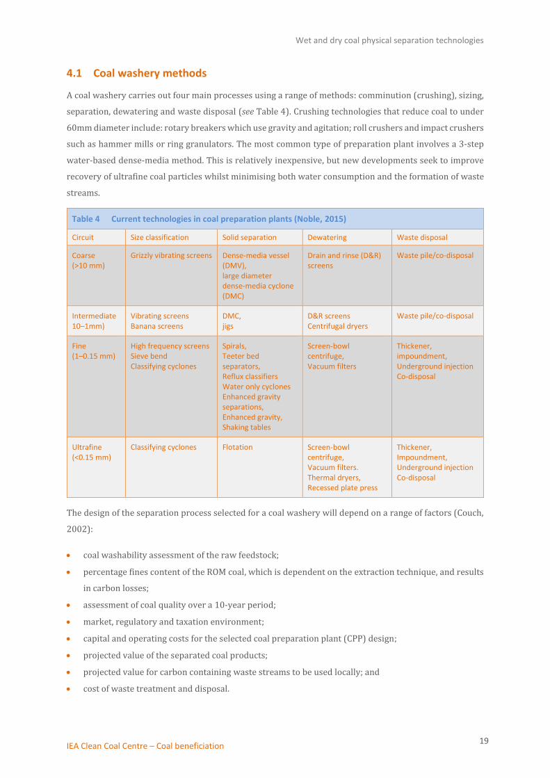
4.1 Coal washery methods
A coal washery carries out four main processes using a range of methods: comminution (crushing), sizing,
separation, dewatering and waste disposal (see Table 4). Crushing technologies that reduce coal to under
60mm diameter include: rotary breakers which use gravity and agitation; roll crushers and impact crushers
such as hammer mills or ring granulators. The most common type of preparation plant involves a 3-step
water-based dense-media method. This is relatively inexpensive, but new developments seek to improve
recovery of ultrafine coal particles whilst minimising both water consumption and the formation of waste
streams.
Table 4 Current technologies in coal preparation plants (Noble, 2015)
Circuit Size classification Solid separation Dewatering Waste disposal
Coarse (>10 mm)
Grizzly vibrating screens Dense-media vessel (DMV), large diameter dense-media cyclone (DMC)
Drain and rinse (D&R) screens
Waste pile/co-disposal
Intermediate 10–1mm)
Vibrating screens Banana screens
DMC, jigs
D&R screens Centrifugal dryers
Waste pile/co-disposal
Fine (1–0.15 mm)
High frequency screens Sieve bend Classifying cyclones
Spirals, Teeter bed separators, Reflux classifiers Water only cyclones Enhanced gravity separations, Enhanced gravity, Shaking tables
Screen-bowl centrifuge, Vacuum filters
Thickener, impoundment, Underground injection Co-disposal
Ultrafine (<0.15 mm)
Classifying cyclones Flotation Screen-bowl centrifuge, Vacuum filters. Thermal dryers, Recessed plate press
Thickener, Impoundment, Underground injection Co-disposal
The design of the separation process selected for a coal washery will depend on a range of factors (Couch,
2002):
• coal washability assessment of the raw feedstock;
• percentage fines content of the ROM coal, which is dependent on the extraction technique, and results
in carbon losses;
• assessment of coal quality over a 10-year period;
• market, regulatory and taxation environment;
• capital and operating costs for the selected coal preparation plant (CPP) design;
• projected value of the separated coal products;
• projected value for carbon containing waste streams to be used locally; and
• cost of waste treatment and disposal.

Wet and dry coal physical separation technologies
IEA Clean Coal Centre – Coal beneficiation 20
Characteristics of the coal (ash content and hardness) and the physical size separation of particulates
determine the efficiency of operation of a coal washery. A partition (Tromp) curve can predict how effective
certain coal washery processes will be in recovering the coal. The partition coefficient obtained using float
analysis is plotted as a function of specific gravity to predict the separation efficiency for a particular
feedstock (Kohmuench, 2000). Bituminous grade coal is the preferred feedstock for coal washeries, but
issues of supply, sulphur content and feed cost mean that increasingly lower rank coals are required to be
treated. The main separation techniques used in coal washeries are summarised below.
Coal preparation plants consist of a series of processing steps, each designed for a specific particle size
range. Inefficiencies arise where the particle size does not fall within the intended range for that circuit.
Water based cleaning processes for the preparation of internationally traded coal aim to divide the raw
coal into the following three categories: clean coal with an ash content of 7–9 wt%; ‘middlings’ with an ash
content of 25–30 wt%; and lastly ’rejects’ containing an ash content of 65–70 wt%.
Figure 2, schematically depicts the flow of coal through the sizing, cleaning and dewatering processes in a
typical coal preparation plant which can treat the full range of particle sizes. Four cleaning circuits treat the
crushed raw coal; coarse, medium, fine and ultrafine particles are treated in separate units, ending with
froth flotation to isolate an ultrafine coal fraction (Luttrell, 2009).
Figure 2 Flowsheet for a typical US coal preparation plant (Luttrell, 2009)
With the feed coal divided by size, most of the cleaned coal is obtained from the coarse treatment circuit.
The flotation cell, designed to separate ultrafine particles, is typically installed for higher value feedstocks,
Wet and dry coal physical separation technologies
IEA Clean Coal Centre – Coal beneficiation 21
and only contributes a few percent of the final coal product; however, on a large installation (25 Mt/y) this
can amount to several hundred thousand tonnes of coal.
A small fraction of coal is unrecovered and passes out of the plant in waste streams; in this way, a high
efficiency coal preparation plant typically loses approximately 10% of the original energy content (Luttrell,
2009). The processing of less tractable composite coals, where the coal and minerals are closely interlaced,
results in higher rejection levels. Such losses can exceed 15% of the heat value of the raw coal feed to
achieve the required coal quality.
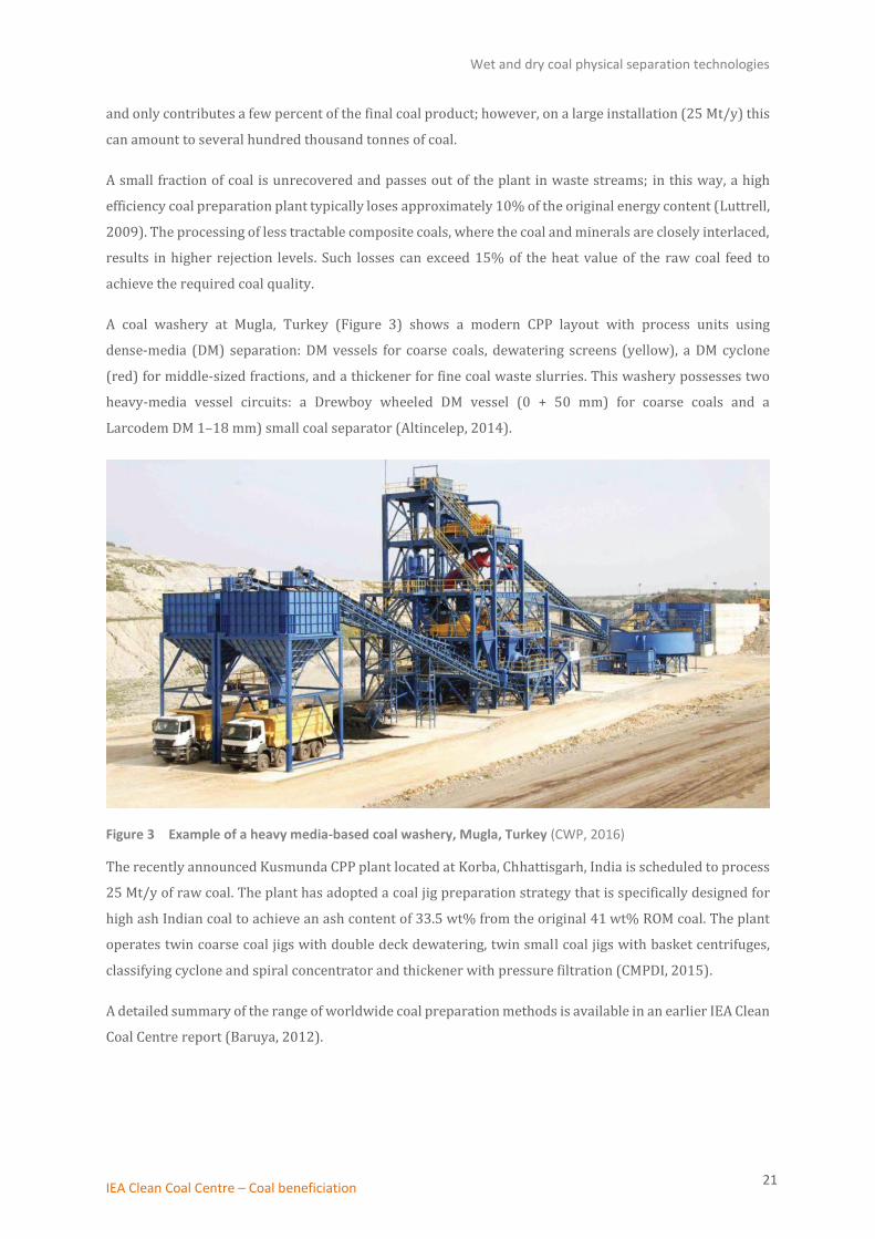
A coal washery at Mugla, Turkey (Figure 3) shows a modern CPP layout with process units using
dense-media (DM) separation: DM vessels for coarse coals, dewatering screens (yellow), a DM cyclone
(red) for middle-sized fractions, and a thickener for fine coal waste slurries. This washery possesses two
heavy-media vessel circuits: a Drewboy wheeled DM vessel (0 + 50 mm) for coarse coals and a
Larcodem DM 1–18 mm) small coal separator (Altincelep, 2014).
Figure 3 Example of a heavy media-based coal washery, Mugla, Turkey (CWP, 2016)
The recently announced Kusmunda CPP plant located at Korba, Chhattisgarh, India is scheduled to process
25 Mt/y of raw coal. The plant has adopted a coal jig preparation strategy that is specifically designed for
high ash Indian coal to achieve an ash content of 33.5 wt% from the original 41 wt% ROM coal. The plant
operates twin coarse coal jigs with double deck dewatering, twin small coal jigs with basket centrifuges,
classifying cyclone and spiral concentrator and thickener with pressure filtration (CMPDI, 2015).
A detailed summary of the range of worldwide coal preparation methods is available in an earlier IEA Clean
Coal Centre report (Baruya, 2012).

Wet and dry coal physical separation technologies
IEA Clean Coal Centre – Coal beneficiation 22
4.1.1 Coal comminution (crushing) and sizing
Unprocessed coal is first conveyed below suspended magnetic separators which remove tramp iron (roof
bolts, ties, wires, and cutting bits) from mining activity. This unit is generally located after coal breakers
but prior to a screen-crusher. The magnets are suspended over the conveyor or at the head pulley;
self-cleaning electromagnets are required for large quantities of tramp iron (Norrgran, 2016; Colorado Air
Pollution Control, 1998).
Subsequently coal is crushed to a suitable processing size before treatment in the washery. A crusher
utilises the softness of coal relative to the hard mineral matter; crushing causes fractures along fissures
within the coal structure requiring minimal application of mechanical force. Crushing equipment normally
comprises rotary breakers and roll crushers, although impact crushers such as hammer mills or ring
granulators may also be used (Kumar, 2012; Eck, 2007). A rotary breaker is generally used to crush and
screen the feedstock to a particle size, typically smaller than 50 mm, which can pass through the breaker
apertures, while the harder shale particles remain unchanged and are rejected.
An advantage of a 50 mm top size is that the coarse coal circuit which includes the dense-media vessel
(DMV) unit shown in Figure 2, may be eliminated in favour of a dense-media cyclone (DMC), simplifying
the coal washery plant (Yoon, 2017). In certain cases, larger diameter DMC can accept coarser coal sizes
reducing crusher energy consumption.
The ease with which a coal sample can be crushed is measured on the Hardgrove Grindability Index. The
sample is assigned a value relative to a standardised coal (value 100); internationally traded coals typically
have an index value in the range 45–70, while harder, less tractable, high ash coals have a lower index value
(GlobalCOAL, 2016).
After crushing, coal is partitioned by size before entering the appropriate coal separation circuit. Typically,
the screen size ranges used are: coarse: larger than 10 mm; intermediate: 1 mm to 10 mm; and fines: less
than 1 mm. Size separation in water-media screening uses single or double deck vibrating screens for
coarse particles although the vibratory derrick sizer screen can have up to five decks stacked one above
the other; multi-slope, double-layered banana screens separate the intermediate fractions; and classifiers
segregate fine coal particles (Bethell, 2007). Roller screens that resist clogging may be utilised for high
moisture content coal.
Stack sizer
In comparison to a single deck screen, a compact stack sizer™ unit offers a larger useful screen area for the
same equipment footprint. As the majority of coal slurry passes through the screen openings near the inlet,
the stack sizer optimises this separation zone by enhancing the effective screen width. The screens are
manufactured from durable urethane with screen openings typically set at 45 to 75 microns. A flow control
device meters a suitable coal slurry flow to each feed box attached to five stacked screens arranged in a
parallel flow formation. The under-size and over-size streams are combined and diverted to appropriate
Wet and dry coal physical separation technologies
IEA Clean Coal Centre – Coal beneficiation 23
separation circuits. A multi-feed point machine arranged in this way may provide up to twice the capacity
of a comparable single feed screen possessing a comparable screen area (Valine, 2009).
Reflux™ Classifier
A Reflux™ Classifier unit can enhance segregation rates of dense mineral particles and improve conveying
of low density coal particles. The process unit consists of a fluidised bed which is located below a system of
inclined channels. In a Reflux™ Classifier the fluidised coal suspension passes up through the inclined
channels formed by a network of plates fixed at a 70-degree angle and at a spacing of 6 mm, specified to
optimise particle separation. Separation of fine coal is enhanced by an emphasis on particle density
properties. Faster settling particles segregate on the sloping surfaces where there is a lower stream velocity
boundary layer, and slide back down to the fluidised zone where dense matter is withdrawn (Galvin, 2005).
Slower settling coal particles in the size range 0.125–2 mm pass through to overflow launders. The actual
particle size range that may be processed in the Reflux™ Classifier can be varied to suit the coal supply but
is governed by a top-to-bottom size ratio limitation of 8:1. The device offers a higher throughput than would
be possible for a fluidised bed alone, possessing a greater hydraulic capacity and offering improved
separation of dilute feedstock (Orupold, 2014).
Hydraulic separators
Hydraulic separators such as the teeter bed, a type of fluidised bed separator, are used for particle size
classification and gravity concentration of coal but performance may be affected by variations in feed
composition. Alternate hydraulic separator designs include the CrossFlow and Hydrofloat separators that
are intended to improve both throughput and the quality of separation.
The Crossfloat design differs from conventional teetered beds by adding a transition feed box to avoid the
high velocity injection of the feedstock slurry into the fluidised region. The revised feed system enables the
coal slurry to be added tangentially across the full width of the separator minimising turbulence. The
advantage of this injection procedure is that it minimises the effect of the slurry solids composition on the
separation process and a constant velocity is maintained across the chamber. This differs from a teeter bed
where the velocity profile varies and increases above the feed injector location. Modifications of the
fluidising water injection system combined with the low turbulence feed addition method improve the
separation, allow higher throughput and reduce distributor blocking while lowering energy and water
requirements. (Luttrell, 2006).
The Hydrofloat separator is intended to process a feedstock possessing a broader size and density range
than a Crossflow separator, including coarse coal particles. The feedstock is treated with a collector to
improve the hydrophobicity of the coal particles and added to an adapted fluidised teeter bed. Compressed
gas present as fine bubbles is injected to aerate the bed and requires a frother agent to be added to the
fluidisation water. Light bubble-particle aggregates rise to the top of the denser teeter bed and are collected
as the overflow from the separation chamber, while the dense mineral particles descend to be discharged
as a high solids stream. The Hydrofloat separator has characteristics of both a teeter bed and a flotation
cell. When compared to a flotation cell the device offers increased throughput in a compact volume and is

Wet and dry coal physical separation technologies
IEA Clean Coal Centre – Coal beneficiation 24
intended to recover coarser coal particles. The device improves bubble-particle contacting, benefitting
from the upward flow of elutriation water which lifts larger particles into the product chamber. The
Hydrofloat device should offer significant energy savings due to the absence of mechanical agitation that is
needed in conventional floatation cells (Luttrell, 2006).
4.1.2 Coarse coal cleaning – dense-media
Coarse coal (exceeding 10 mm) cleaning is normally undertaken using a dense-media bath or vessel; coal
and impurities (ash) are separated using specific gravity (SG) methods. The SG of coal is normally in the
range 1.3–1.5, compared to rock with an SG exceeding 2.2; a separation point is selected at an SG of typically
1.6–1.65. A dense-media vessel processes a slurry of coal, magnetite (iron oxide mineral Fe3O4, SG >4.9) and
water; the less dense, particles with a high carbon content float to the surface while the rocky particulates
containing sulphur, ash and mercury, sink to the base of the vessel.
The potential effectiveness of wash operations on an unprocessed, powdered coal may be assessed by a
laboratory float/sink analysis, whereby coal float and rejects are separated in a series of flasks containing
organic solvents of gradually increasing density. The float from the lowest density liquid (SG=1.3) may
constitute up to half of the original coal sample dependent on coal characteristics. This fraction would
possess a low ash yield, with subsequent vessels showing a higher ash yield at each stage. The optimum SG
separation point is in the region of 1.6, a compromise between minimal ash and maximum carbon recovery.
The separation medium is a slurry mixture of magnetite in water that is circulated through the DMV. The
coal added to this mixture floats to the surface and overflows into a collection screen, while the higher
density waste rock sinks to the base of the vessel to be collected by scrapers or flights. Optimum separation
is achieved where the particle size is greater than 10 mm, as there is insufficient time for the settling of fine
matter; fines content is generally limited to <2 wt% in order that the refuse carrying capacity of the vessel
is not affected (Jain, 2016). Both the washed coal and waste are passed over drain and rinse screens.
Magnetite flows into a magnetic circuit fitted with a mounted steel drum containing an interior fixed
magnet for magnetite recovery and reuse (Norrgran, 2016). The dense-media washing process typically
rejects about 20–40% of the ROM coal feed.
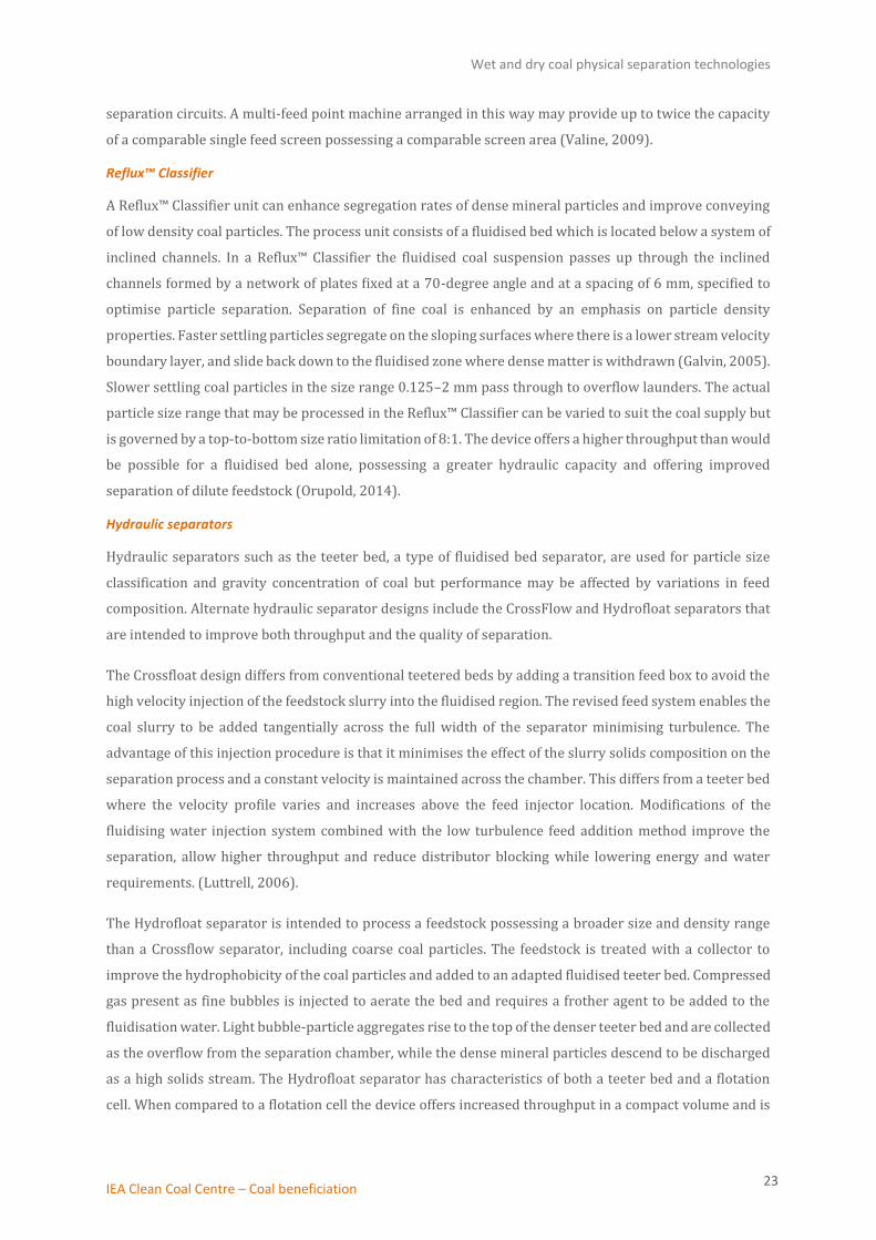
4.1.3 Intermediate coal cleaning – dense-media cyclone
A dense-media cyclone method is used to treat the medium-size fraction of coal (10 to 1 mm) separated by
a deslime screen; a static DM vessel is unsuitable since medium particles would take too long to settle. The
cyclone consists of a conical vessel cast in high chrome cast iron or from steel lined with either ceramic tiles
or nickel based alloys to protect the outer vessel (see Figure 4). The medium coal feed fraction combined
with finely ground magnetite in water (termed pulp) is pumped tangentially at optimum pressure into the
inlet pipe of the cyclone, swirling to create a vortex.
Wet and dry coal physical separation technologies
IEA Clean Coal Centre – Coal beneficiation 25
Figure 4 DM intermediate coal cyclone arranged at a 15° angle (Parnaby, 2016)
The centrifugal effect draws higher density rock and ash downwards to pass out of the spigot (apex) as
rejects or middlings, while lighter carbon particles are carried in an upward flow and exit as clean coal
through the cyclone overflow outlet. The cyclone design features a spigot outlet that is too small to
accommodate the entire flow, forcing a fraction of the flow containing lighter coal particles to exit at the
top, at the vortex finder. The denser media are drawn to the surface of the cyclone while an inner spiral of
lighter matter flows in the counter direction. While the operation of a cyclone requires minimal
maintenance due to the absence of moving parts, the unit is prone to occasional jamming that is detected
by changes in operating pressure (Gluskoter, 2009).
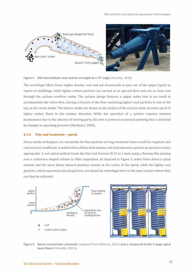
4.1.4 Fine coal treatment – spirals
Dense-media techniques, are unsuitable for fine particles as long treatment times would be required, and
coal recovery inefficient. A method that utilises both density and hydrodynamic particle properties is more
appropriate. A wet spiral method treats the fine coal fraction (0.15 to 1 mm) using a flowing film passing
over a corkscrew shaped column to effect separation. As depicted in Figure 5, water flows down a spiral
channel and the more dense mineral particles remain in the centre of the spiral, while the lighter coal
particles, which experience less drag forces, are drawn by centrifugal force to the outer surface where they
can then be collected.
Figure 5 Spiral concentrator schematic (adapted from Osborne, 2013) and a compound Krebs 2-stage spiral bank fitted (FLSmidth, 2017a)

Wet and dry coal physical separation technologies
IEA Clean Coal Centre – Coal beneficiation 26
Two stage spiral circuits are used to maximise coal recovery. The first stage produces a reject stream, while
a second stage produces a clean coal product and reject. The middlings produced from the second stage are
recycled back to the inlet of the spiral circuit for reprocessing (Yoon, 2017). Table 5 shows an example of
the distribution of coal from compound spirals per specific gravity fractions
Table 5 Separation results obtained using a compound spiral system fitted with slurry repulping boxes (Bethell, 2003)
SG Fraction Coal product, %
1.6 float 97.3
1.6 x 1.8 1.05
1.8 sink 1.03
Dense matter (heavies) 0.56
The device employs a density separation method, and optimum conditions are achieved when particle
fractions are of near uniform size, which also facilitates the hydrodynamic flow effect. Inefficiencies arise
from the introduction of a wide range of particle sizes or material exceeding the design range. Optimal
spiral operating conditions are met by utilising a coal feed slurry that contains up to 30% solids with a
particle size range of 1 to 0.15 mm.
4.1.5 Fine or ultrafine coal circuit – flotation and agglomeration
Coal flotation is widely practiced on higher quality coal supplies to clean coal that is of less than
600 microns (preferably 0.15 to 0 mm). Flotation cells make use of the hydrophobic property of coal
particles and the method is suitable for ultrafine particles that cannot be separated by density techniques.
The hydrophobicity of the coal is enhanced by the addition of chemical reagents termed frother or collector
that are premixed with water and then added to the fine coal–water slurry prior to entering a flotation cell.
In practice a minimal excess of chemical reagents is applied to optimise coal recovery (Bulatovic, 2014).
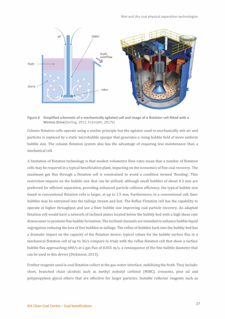
A schematic of a mechanically agitated flotation cell is shown in Figure 6; the rotor draws the fine coal
slurry through the stator and expels it to the side, creating a partial vacuum that draws air down the shaft
of the stator to aerate the slurry. Alternate designs such as Outotec and Dorr-Oliver cells use pressurised
air blowers, while stackcells offer a compact design that utilises a pre-aerated high shear feed chamber for
bubble particle contacting (Jones, 2011). Air bubbles are dispersed throughout the slurry and contact the
hydrophobic coal particles that are then drawn by the air bubble buoyancy to form a surface froth. The
froth layer flows over the discharge lip either by gravity or by using froth scrapers.
Wet and dry coal physical separation technologies
IEA Clean Coal Centre – Coal beneficiation 27
Figure 6 Simplified schematic of a mechanically agitated cell and image of a flotation cell fitted with a Wemco Drive(Darling, 2011; FLSmidth, 2017b)
Column flotation cells operate using a similar principle but the agitator used to mechanically mix air and
particles is replaced by a static microbubble sparger that generates a rising bubble field of more uniform
bubble size. The column flotation system also has the advantage of requiring less maintenance than a
mechanical cell.
A limitation of flotation technology is that modest volumetric flow rates mean that a number of flotation
cells may be required in a typical beneficiation plant, impacting on the economics of fine coal recovery. The
maximum gas flux through a flotation cell is constrained to avoid a condition termed ‘flooding’. This
restriction impacts on the bubble size that can be utilised; although small bubbles of about 0.3 mm are
preferred for efficient separation, providing enhanced particle collision efficiency, the typical bubble size
found in conventional flotation cells is larger, at up to 1.5 mm. Furthermore, in a conventional cell, finer
bubbles may be entrained into the tailings stream and lost. The Reflux Flotation cell has the capability to
operate at higher throughput and use a finer bubble size improving coal particle recovery. An adapted
flotation cell would have a network of inclined plates located below the bubbly bed with a high shear rate
downcomer to promote fine bubble formation. The inclined channels are intended to enhance bubble liquid
segregation reducing the loss of fine bubbles to tailings. The reflux of bubbles back into the bubbly bed has
a dramatic impact on the capacity of the flotation device; typical values for the bubble surface flux in a
mechanical flotation cell of up to 36/s compare to trials with the reflux flotation cell that show a surface
bubble flux approaching 600/s at a gas flux of 0.055 m/s, a consequence of the fine bubble diameter that
can be used in this device (Dickinson, 2013).
Frother reagents used in coal flotation collect at the gas-water interface, stabilising the froth. They include:
short, branched chain alcohols such as methyl isobutyl carbinol (MIBC), creosotes, pine oil and
polypropylene glycol ethers that are effective for larger particles. Suitable collector reagents such as
Wet and dry coal physical separation technologies
IEA Clean Coal Centre – Coal beneficiation 28
No 2 fuel-oil and kerosene are added after the frother reagent to enhance the hydrophobicity of the coal
particles.
Oil agglomeration is an alternative separation method for fine particles, where high sheer forces are applied
to coal slurry that is mixed with an agglomerating liquid such as diesel fuel, fuel oil, heptane or pentane. At
high shear rate the water is stripped from the coal particle to be replaced by the agglomerating agent that
acts to separate the coal from the mineral matter, and avoids a subsequent dewatering step. There are a
number of technology variants that include: a ‘spherical agglomeration process’ which has a compacting
step; a ‘shell pelletising separator’ that forms 3 cm pellets and reports a high recovery of coal (95%) and
high ash rejection (to 95%); an ‘Olifloc process’ using 15% fuel oil; and the ‘SFRI process’ that uses a
combination of diesel and heavy oil for less tractable coal (Bulatovic, 2014).
4.1.6 Dewatering
Water is removed from processed coal at the end of each treatment circuit to reduce the overall mass,
improve the energy content (calorific value, CV) and to avoid stockpile run-off. Coarse and medium coal is
typically dried by dewatering screens or centrifuges, whereas fine coal dewatering requires filtration
(using belt or vacuum filters). To remove the ash from lower quality, high ash coals it is necessary to crush
the feedstock to a fine particle size, which often results in increased moisture levels in the clean coal. An
area of processing concern is the loss of ultrafine coal particles which accumulate in the thickener and are
lost in the waste stream.
Coarse coal (>10 mm)
The dewatering of larger coal particles is normally achieved by using drain and rinse (D&R) screens. Solids
are captured and exit from the base of the screen, while water passes through fissure grids to discharge via
the screen slot. The durability of the screen equipment to resist abrasion has a significant impact on the
overall operating costs of a coal washery (O’Bryan, 2016).
In practice, some plants combine the streams of coarse and intermediate-sized wet coal particles prior to
dewatering; a vibrating centrifuge is employed, the coal is conveyed by vibratory action into the centrifuge
at rates approaching 300 t/h. The vibratory centrifuge method for coarse coal separation has high
efficiency and low operational costs (Eraydin, 2016).
Intermediate coal (1–10 mm, 18 mesh)
Although the intermediate coal fraction may be combined with coarse coal for separation in a vibratory
centrifuge, an option is to use a screen-scroll centrifuge which can operate at higher velocity, to improve
dewatering efficiency. Although a more efficient method, the higher mechanical forces of the scroll design
can result in the unit suffering from increased maintenance costs due to wear and tear. The screen-scroll
centrifuge can reduce the water content of the coal stream by approximately 5% more than the vibratory
device.

Wet and dry coal physical separation technologies
IEA Clean Coal Centre – Coal beneficiation 29
Fine coal (0.15–1 mm)
Fine coal contains a higher level of moisture than coarser grades. After treatment in the fine particle
cleaning circuit which uses a spiral separator, tilted bed unit or reflux classifier the resultant coal slurry
may possess up to 80% moisture. The slurry enters a fine coal centrifuge which is generally either a screen-
scroll centrifuge (SSC) or a screen-bowl centrifuge (SBC). These machines are designed to process 80 t/h
of fine coal slurry and can achieve moisture levels of 40 to 60%. The slurry is pre-processed through
desliming cyclones and sieves to ensure that the very fine matter is less than 5% of the solid content to
optimise efficient operation of the centrifuge.
The Somerset SUB325 centrifuge has extended the recovery range down to 44 microns (325 mesh). The
revised design uses a hydraulically-driven solid-bowl centrifuge that can achieve coal recovery of almost
95%. At the same time the water content is reduced from 80% to about 50%, to achieve less than 20%
moisture once recycled coarser coal is included (Somerset, 2016). The redesign of the SUB325 centrifuge
(see Figure 7), involves optimisation of the G-force (force obtained by acceleration) and torque (force
causing rotation). A new hydraulic, variable speed drive permits optimisation of the rotational difference
between the rotating bowl and the centrifuge helical scroll.
Figure 7 Sub325 Centrifuge to dewater fine coal (Somerset, 2016)
The equipment can process up to 25 L/s and has recently completed a 4-month commercial trial.
The centribaric centrifuge from Decanter Machine has improved upon performance from centrifugation
alone by using gas pressure to increase moisture reduction. The unit is a combination of pressure filtration
that employs a filter cloth and centrifugation in one device. The processing conditions include air pressures
of up to 0.25 MPa and the application of centrifugal force of approximately 2000G (Asmatulu, 2005). The
centribaric centrifuge can achieve less than 25% moisture from a mixture of 50% 325 mesh screen-bowl
effluent and 50% <0.5 mm screen drain (Yoon, 2017).
These methods enable a smaller particle range to be collected, which leads to more efficient operation of a
flotation cell bank and a substantial reduction in the chemical demand required for the thickener.

Wet and dry coal physical separation technologies
IEA Clean Coal Centre – Coal beneficiation 30
Ultrafine coal (<0.15 mm,)
Advances in centrifuge technology are significant in extending the range of particle size that can be
recovered by high-volume and low-cost methods. Currently, ultrafine coal is dewatered by filtration, but
the high cost means that this is normally employed for metallurgical coal applications. For belt presses,
flocculants are added to form coal agglomerates that allow water to drain easily through filter cloths at low
pressure. Other filtration techniques, such as ‘plate and frame’ and ‘filter presses’ use systems that require
10 bar (1 MPa) of differential pressure. Hyperbaric filtration that applies a greater pressure differential is
used to further lower the water content. Whichever method is adopted, addition of shear resistant
chemicals at minimal practical dosage rates can enhance the moisture reduction efficiency. The addition of
surfactants raises particle hydrophobicity; these reagents combine to improve filtration kinetics resulting
in significantly enhanced moisture reduction to meet specifications of between 7–8.5% water content. In
addition, where further water removal is required, the vacuum filtered coal then undergoes thermal drying
(Eraydin, 2016).
Waste streams
New rigorous environmental standards mean that it is increasingly inappropriate to discharge CPP tailing
streams to slurry impoundment for subsequent disposal. The coal industry is seeking acceptable methods
of handling the waste streams; these include recovering ultrafine coal from tailings using the latest
techniques and removal of water from tailings to form a recycle water stream. This approach also addresses
increasing concerns about water conservation.
After the tailings slurry is dosed with flocculants it passes to a thickener. A thickener is a large circular tank
of up to 40 m diameter that is equipped with slowly rotating rakes used to settle out the solid material from
the water in the feed slurry. Plate and frame filters or belt presses can be used in this part of the process to
dewater the settling fine refuse. The formation of a ‘filter cake’ within these devices, effectively performs
the filtration duty; the separated water is clarified and reused as process water in the CPP (Klima, 2015).
The inclusion of waste slurry treatment in the CPP plant can reduce the fresh water requirement of the
plant by 60%, although care must be taken to avoid overloading the coarse coal circuit with fine matter.
4.2 Dry coal beneficiation
Dry coal separation, also termed pneumatic cleaning or air table destoning, is of growing relevance due to
the emerging shortage of water supply to manufacturing and thermal power industries. The water
requirement for a subcritical thermal power station is approximately 2 t/MWh (for example 1000 t/h for
a 500 MW station), but this excludes the water consumed in the preparation of the coal.
China is the largest coal producer and consumer and 70% of the coal reserves are located in arid regions,
where not only is there significant competition for fresh water, but there are also harsh winters, which can
prevent the application of wet coal preparation techniques (Zhao, 2014). In response, the power industry
is exploring the use of alternative water sources such as extracted mine water, municipal wastewater and
seawater from desalination. In times of water shortage, if an alternative supply is not available, thermal
coal stations in India had to cease operations. Indeed, the situation is becoming more critical as

Wet and dry coal physical separation technologies
IEA Clean Coal Centre – Coal beneficiation 31
consumption of fresh water is predicted to rise by 50% in the period 2016 to 2050; this resource constraint
is likely to impact all aspects of the coal supply chain including the coal preparation technology. More
information on the management of water resources in the power industry is available in a series of reports
prepared by the IEA Clean Coal Centre (Carpenter, 2015 and 2016).
Historically, dry separation methods were considered to be little better than the simple destoning of coal
and therefore much inferior to wet processing technologies. However, dry separation methods are much
improved although not as effective as comparable dense-media separators for medium and coarse coal
(Colorado Air Pollution Control, 1998; Zhao, 2014).
The effectiveness of a coal separation method may be assessed by examining the particle efficiency (Ep)
value; this provides a measure of the particle density difference at 25% and 75% coal partition. Lower Ep
values indicate a more efficient separation and low ash content (Zhao, 2014). The particle efficiency (Ep)
is defined by the following equation:
Ep = (ƿ25 – ƿ75)/ 2
Wet separation Ep values are normally in the range 0.01–0.05, while for dry methods the reported range
of 0.07–0.25 particle efficiency indicates an incremental rise in the ash content of the cleaned coal at the
higher end of the scale. If applied to a suitable coal feedstock, dry processing technology can result in a
similar quality coal product to that obtained by wet preparation methods.
Dry processing offers several potential advantages including: an improved coal energy content due to
reduced water content; ease of plant construction; capital cost reduced relative to comparable sections of
a wet beneficiation plant; and a reduction in waste slurry waste (Korte, 2014). However, operation under
dry conditions requires extensive gas and dust handling infrastructure for safe management of the
operation.
Dry separation techniques are under development to exploit different aspects of coal particle properties
that include: coal density, particle shape, friction, electrostatics, and magnetism. The current dry
beneficiation methods for coarse and fine particle sizes are described below:
For coarse particles:
• Air dense-media fluidised bed separation (ADMFB) – vibration energy is applied to a mixture of
powdered coal and magnetite present as the separating medium, utilising the density/sink-float
principle (Luo, 2002).
• Fluidised bed separation – similar to ADMFB omitting the use of magnetite, agitation of particles
releases coal from denser mineral matter (Yang, 2013).
• Compound dry separation – air table separation that exploits several coal properties: particle friction,
shape and density. This category dominates commercial dry separators and includes air jigs and the
FGX dry separator, described in the next section.

Wet and dry coal physical separation technologies
IEA Clean Coal Centre – Coal beneficiation 32
For finer particles, not yet commercialised:
• Tribo-electrostatic separation – fine particles (200 mesh) are charged by dust charging mechanisms,
passed through an electric field that deflects particles according to magnitude and sign of the particle
charge. Coal becomes positively charged; quartz kaolin, pyrite and calcite negatively charged,
allowing separate collection of cleaned coal and reject (Zhang, 2009).
• Magnetic separation – the difference in magnetic properties enables the separation of the coal and
mineral matter passed through a powerful magnetic field (Subba Rao, 2016).
The lowest cost dry separation methods, and consequently the most deployed technologies use air jigs and
of these the commercial leader is the FGX separator. The fluidised bed technology loses a greater fraction
of material to middlings reducing coal recovery, while the ADFMB method suffers from the cost of
magnetite recovery and associated losses. Due to the higher cost involved, the techniques outlined for fine
coal particles are restricted to specialist applications rather than steam coal. The following section
examines the widely-used air table technology in more detail.
4.2.1 Air jigs and FGX Dry Separator
The dry-cleaning jig operates using a similar separation mechanism to that of a wet cleaning jigging
machine but water is replaced by compressed air. Figure 8 shows an Allair pneumatic jig that is an
adaptation of an earlier wet jig design which can process a wide range of coal feedstocks. Raw coal is fed
into the jig from a hopper and subjected to a combination of vibration and air pulses applied through a
perforated table. The material on the deck becomes loosened and stratified according to the material
density.

Wet and dry coal physical separation technologies
IEA Clean Coal Centre – Coal beneficiation 33
Figure 8 Adapted Stomp coal air jig (Allair, 2016)
Heavier mineral matter sinks to the bottom of the bed and is then rejected, while lighter matter consisting
of coal rich particles, floats to the top of the bed. Gradually a steady state is achieved and a material bed is
formed which aids the separation through inter-particle agitation. Allair jig units can process up to 100t/h
of a full range of coals from brown to bituminous grade.
The FGX separator developed in China (Zhao, 2014) was designed for the treatment of coarse coal sizes; it
is the most widely used dry coal cleaning unit with over 2000 FGX installations in operation. Most of the
units are in China, but have been installed in the majority of coal-producing countries.
An FGX dry beneficiation plant consists of a coal feeder, separating compartment, air blower, draught fan,
and two-stage dust collecting system. The separating compartment includes a perforated deck, vibrators,
air chamber, and hanging mechanism (Figure 9).
Wet and dry coal physical separation technologies
IEA Clean Coal Centre – Coal beneficiation 34
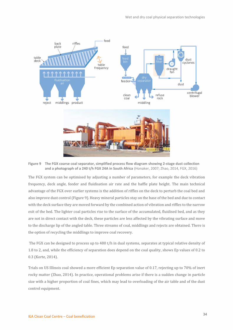
Figure 9 The FGX coarse coal separator, simplified process flow diagram showing 2-stage dust collection and a photograph of a 240 t/h FGX 24A in South Africa (Honaker, 2007; Zhao, 2014, FGX, 2016)
The FGX system can be optimised by adjusting a number of parameters, for example the deck vibration
frequency, deck angle, feeder and fluidisation air rate and the baffle plate height. The main technical
advantage of the FGX over earlier systems is the addition of riffles on the deck to perturb the coal bed and
also improve dust control (Figure 9). Heavy mineral particles stay on the base of the bed and due to contact
with the deck surface they are moved forward by the combined action of vibration and riffles to the narrow
exit of the bed. The lighter coal particles rise to the surface of the accumulated, fluidised bed, and as they
are not in direct contact with the deck, these particles are less affected by the vibrating surface and move
to the discharge lip of the angled table. Three streams of coal, middlings and rejects are obtained. There is
the option of recycling the middlings to improve coal recovery.
The FGX can be designed to process up to 480 t/h in dual systems, separates at typical relative density of
1.8 to 2, and, while the efficiency of separation does depend on the coal quality, shows Ep values of 0.2 to
0.3 (Korte, 2014).
Trials on US Illinois coal showed a more efficient Ep separation value of 0.17, rejecting up to 70% of inert
rocky matter (Zhao, 2014). In practice, operational problems arise if there is a sudden change in particle
size with a higher proportion of coal fines, which may lead to overloading of the air table and of the dust
control equipment.

Wet and dry coal physical separation technologies
IEA Clean Coal Centre – Coal beneficiation 35
Dry separators are normally restricted to the processing of coarse coal in the 6–80 mm size range. The new
TFX-8 air jig extends the range of coal particles that can be dry-separated to include smaller coal particles
(0.2–10 mm). The TFX-8 has a 2-stage vibratory bed to produce a coal, middlings and two reject streams,
and is capable of processing 130 t/h of feed ROM coal with an Ep value of 0.2 which is comparable to an
FGX unit. Previously, ash rejection from small coal separators has been poor, whereas, TFX-8 separation
data for a high-ash Indian thermal coal shows the following streams (Tangshan, 2016):
• Clean coal: ash reduction from 42% to 27% at 59% yield;
• Middlings: ash content 55% at 22% yield;
• Rejects: 73% ash content at 19% yield.
4.2.2 X-ray sorting
The Technical University of Delft developed an x-ray sorting method to separate coal on a piece-by-piece
basis. Raw coal falls from a conveyor past an x-ray source to one side and detector to the other; each particle
is scanned and the extent of x-ray absorption measured (Figure 10). Mineral shale particles absorb x-ray
radiation more effectively and show as a dark image, whereas less dense coal particles have a lighter image.
The images are processed in ‘real-time’ and a set of air nozzles activated to send a compressed air jet to
move coal to the collector while heavier mineral matter is rejected (Kiser, 2005)
Figure 10 X-ray ore sorting device DriJet™ (Kumar, 2014; Kiser, 2005)
Isambane Mining, SA trialled the x-ray sorter and found the coal could be cut at a relative density of between
1.8 to 2.1. This is similar to the performance of an FGX separator, but shows a slightly improved Ep value
of 0.15–0.2. The x-ray sorter proved most efficient on coarse coal particles exceeding 30 mm; smaller coal
sizes could be sorted if the feed rate was reduced below the intended 100 t/h. A suggested application of
the Drijet™ x-ray sorter is that it might be operated in conjunction with an FGX air bed separator and used
to improve processing of the middlings fraction, improving the overall recovery rate (Korte, 2014).

Wet and dry coal physical separation technologies
IEA Clean Coal Centre – Coal beneficiation 36
4.3 Hydrophobic hydrophilic 2-liquid separation (HHS) for ultrafine coal slurries
Hydrophobic-hydrophilic separation (HHS) is a novel process for the separation of ash from ultrafine coal
particles to improve the recovery of coal and reduce tailings rejects. The process has been developed in a
partnership between Virginia Tech and the Minerals Refining Company, both in the USA (Gupta, 2016; Yoon
and others, 2016). The process uses the disparate surface chemistry properties of coal and ash to separate
and dewater fine and ultrafine coal (to 325 mesh) from clay and moisture. Pilot plant trials assessed the
effectiveness of the technology separating US bituminous coal waste slurry; this process reduced the water
content from over 30% to below 4%, while the ash content was reduced from 65% to less than 5%. The
specification of the dry, cleaned coal product lies well within that of internationally-traded coal (Table A1).
Figure 11 Hydrophobic-hydrophilic separation process (Gupta, 2016)
A coal-waste feed slurry derived from reject streams taken either from screen-bowl centrifuges or
desliming cyclones is separated from water and ash-forming minerals by combining the slurry with a
hydrophobic liquid (Figure 11). The two liquids are first mixed and then phase separated, leaving the water
and hydrophilic ash-forming minerals (such as clays) in the aqueous phase, while the hydrophobic
(organic) coal is dispersed into the hydrophobic liquid phase. A suitable hydrophobic liquid could be a short
chain alkane such as pentane or a light oil distillate. The coal immersed in hydrophobic liquid is passed to
an upgrading unit (termed Morganizer) where emulsions are destabilised to release the coal particles, with
water and waste matter collecting at the base. The coal particle immersed in the hydrophobic liquid retains
no surface moisture. The coal particles can be separated from the hydrophobic liquid by conventional
filtration while any residual hydrophobic liquid left on the coal surface is stripped off by vaporisation and
condensation. Selection of low boiling point, non-hydrogen bonded liquids requires minimal vaporisation
energy, much less than for equivalent water evaporation technologies, with the recovered liquid reused in
the process.
In comparison to conventional froth flotation, HHS is considered to offer a superior performance on
ultrafine particles. Froth flotation would require a longer retention time, larger vessels and additional
cleaning and scavenging stages. The HHS process eliminates the need for costly final dewatering of the
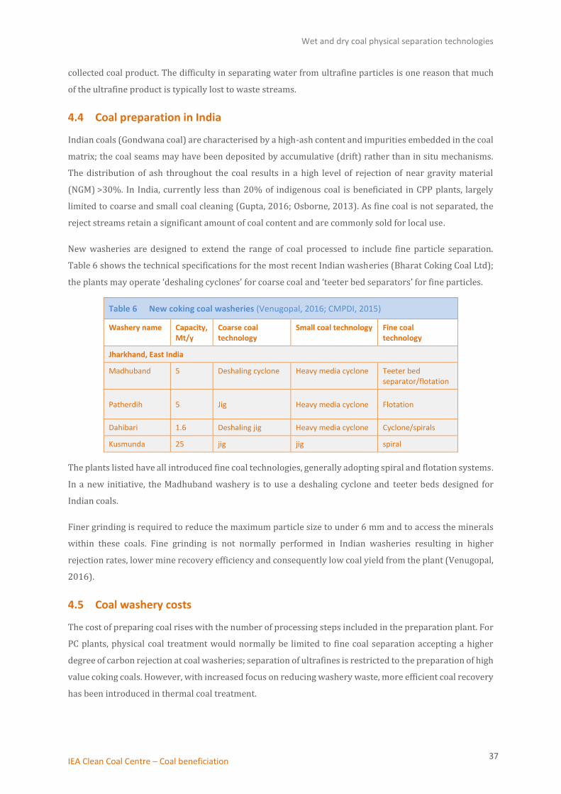
Wet and dry coal physical separation technologies
IEA Clean Coal Centre – Coal beneficiation 37
collected coal product. The difficulty in separating water from ultrafine particles is one reason that much
of the ultrafine product is typically lost to waste streams.
4.4 Coal preparation in India
Indian coals (Gondwana coal) are characterised by a high-ash content and impurities embedded in the coal
matrix; the coal seams may have been deposited by accumulative (drift) rather than in situ mechanisms.
The distribution of ash throughout the coal results in a high level of rejection of near gravity material
(NGM) >30%. In India, currently less than 20% of indigenous coal is beneficiated in CPP plants, largely
limited to coarse and small coal cleaning (Gupta, 2016; Osborne, 2013). As fine coal is not separated, the
reject streams retain a significant amount of coal content and are commonly sold for local use.
New washeries are designed to extend the range of coal processed to include fine particle separation.
Table 6 shows the technical specifications for the most recent Indian washeries (Bharat Coking Coal Ltd);
the plants may operate ‘deshaling cyclones’ for coarse coal and ‘teeter bed separators’ for fine particles.
Table 6 New coking coal washeries (Venugopal, 2016; CMPDI, 2015)
Washery name Capacity, Mt/y
Coarse coal technology
Small coal technology Fine coal technology
Jharkhand, East India
Madhuband 5 Deshaling cyclone Heavy media cyclone Teeter bed separator/flotation
Patherdih 5 Jig Heavy media cyclone Flotation
Dahibari 1.6 Deshaling jig Heavy media cyclone Cyclone/spirals
Kusmunda 25 jig jig spiral
The plants listed have all introduced fine coal technologies, generally adopting spiral and flotation systems.
In a new initiative, the Madhuband washery is to use a deshaling cyclone and teeter beds designed for
Indian coals.
Finer grinding is required to reduce the maximum particle size to under 6 mm and to access the minerals
within these coals. Fine grinding is not normally performed in Indian washeries resulting in higher
rejection rates, lower mine recovery efficiency and consequently low coal yield from the plant (Venugopal,
2016).
4.5 Coal washery costs
The cost of preparing coal rises with the number of processing steps included in the preparation plant. For
PC plants, physical coal treatment would normally be limited to fine coal separation accepting a higher
degree of carbon rejection at coal washeries; separation of ultrafines is restricted to the preparation of high
value coking coals. However, with increased focus on reducing washery waste, more efficient coal recovery
has been introduced in thermal coal treatment.
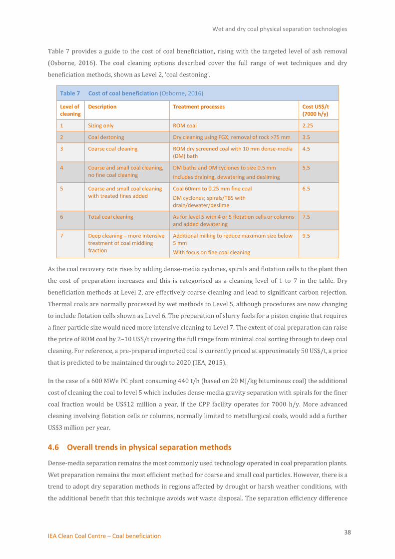
Wet and dry coal physical separation technologies
IEA Clean Coal Centre – Coal beneficiation 38
Table 7 provides a guide to the cost of coal beneficiation, rising with the targeted level of ash removal
(Osborne, 2016). The coal cleaning options described cover the full range of wet techniques and dry
beneficiation methods, shown as Level 2, ‘coal destoning’.
Table 7 Cost of coal beneficiation (Osborne, 2016)
Level of cleaning
Description Treatment processes Cost US$/t (7000 h/y)
1 Sizing only ROM coal 2.25
2 Coal destoning Dry cleaning using FGX; removal of rock >75 mm 3.5
3 Coarse coal cleaning ROM dry screened coal with 10 mm dense-media (DM) bath
4.5
4 Coarse and small coal cleaning, no fine coal cleaning
DM baths and DM cyclones to size 0.5 mm
Includes draining, dewatering and desliming
5.5
5 Coarse and small coal cleaning with treated fines added
Coal 60mm to 0.25 mm fine coal
DM cyclones; spirals/TBS with drain/dewater/deslime
6.5
6 Total coal cleaning As for level 5 with 4 or 5 flotation cells or columns and added dewatering
7.5
7 Deep cleaning – more intensive treatment of coal middling fraction
Additional milling to reduce maximum size below 5 mm
With focus on fine coal cleaning
9.5
As the coal recovery rate rises by adding dense-media cyclones, spirals and flotation cells to the plant then
the cost of preparation increases and this is categorised as a cleaning level of 1 to 7 in the table. Dry
beneficiation methods at Level 2, are effectively coarse cleaning and lead to significant carbon rejection.
Thermal coals are normally processed by wet methods to Level 5, although procedures are now changing
to include flotation cells shown as Level 6. The preparation of slurry fuels for a piston engine that requires
a finer particle size would need more intensive cleaning to Level 7. The extent of coal preparation can raise
the price of ROM coal by 2–10 US$/t covering the full range from minimal coal sorting through to deep coal
cleaning. For reference, a pre-prepared imported coal is currently priced at approximately 50 US$/t, a price
that is predicted to be maintained through to 2020 (IEA, 2015).
In the case of a 600 MWe PC plant consuming 440 t/h (based on 20 MJ/kg bituminous coal) the additional
cost of cleaning the coal to level 5 which includes dense-media gravity separation with spirals for the finer
coal fraction would be US$12 million a year, if the CPP facility operates for 7000 h/y. More advanced
cleaning involving flotation cells or columns, normally limited to metallurgical coals, would add a further
US$3 million per year.
4.6 Overall trends in physical separation methods
Dense-media separation remains the most commonly used technology operated in coal preparation plants.
Wet preparation remains the most efficient method for coarse and small coal particles. However, there is a
trend to adopt dry separation methods in regions affected by drought or harsh weather conditions, with
the additional benefit that this technique avoids wet waste disposal. The separation efficiency difference

Wet and dry coal physical separation technologies
IEA Clean Coal Centre – Coal beneficiation 39
between wet and dry methods has substantially reduced and dry techniques are now extended to include
small coal sizes.
The focus of industry development is on the recovery of fine and ultrafine particles to improve recovery
efficiency, partly driven by a period of high coal prices, but primarily to reduce waste and ease waste
disposal. Increasingly CPP facilities are introducing froth flotation separation methods to thermal coal
preparation, and advances in dewatering techniques recover fine particles rather than lose them to tailings.
New methods such as 2-liquid hydrophobic-hydrophilic separation may offer an alternative to froth
flotation for recovery of a dry fine coal product.
Given the coal consumption trends, it is probable that the greatest demand for new CPP facilities will occur
in India, where there is a pressing need to improve the quality of the indigenous coal. Indian coals are
resistant to physical separation methods and produce coal with residual ash levels of about 30%. Based on
coal separation assessments and experience, the technologies adopted are based on coal jigs, dense-media
cyclones and include fine coal recovery in new facilities.
Thermal coal beneficiation (coal refining)
IEA Clean Coal Centre – Coal beneficiation 40
5 Thermal coal beneficiation (coal refining)
Coal preparation plants treat raw coal to remove mineral matter but organically-bound sulphur and
mercury are not removed by such methods. The following section describes recently implemented thermal
coal technologies that access the volatile components in coal to reduce contaminants. The processes
include: a 3-stage drying process to produce low moisture, stabilised coal suitable for long distance
transport; technology that combines pyrolysis and fractionation recovering a liquid product; a thermal
beneficiation module immediately upstream of the boiler to prepare coal for gasification accompanied by
desulphurisation under fuel rich combustion conditions; and a hydrothermal coal drying technique.
5.1 Thermally stabilised coal
The Pristine-M™ process is under development in the USA. It is designed to treat high moisture
subbituminous or lignite coal supplies by moderate heating l to remove moisture, pollutant precursors and
other volatiles. The result is a thermally stabilised fuel which is cleaner and has an enhanced energy content
(Eves, 2016).
In a conventional thermal coal coking plant, coal passes through three temperature regimes: initial
decomposition of the coal occurs at 375–475°C; devolatilisation of gaseous components followed by
re-solidification is completed at 475–600°C, and coke stabilisation is achieved at 600–1100°C, before the
final pushing and quenching of the coke.
In comparison, the thermally stabilised coal treatment described here is a process conducted below 450°C
that is intended to partially dry and devolatilise coal. The process conditions are roughly comparable to the
first stage of coal decomposition in a coking plant.
The overall process, shown in Figure 12, first removes gas and liquid volatiles (<7% of the mass) during
initial heating of the coal in an inert atmosphere, prior to a drying phase that takes place at 121°C using
Carrier dryers. The degree of drying is set to match boiler requirements for the feed which is normally
specified at 10% moisture content. At lower throughput 5% water content may be achieved by increasing
the residence time the coal spends within the dryer. A second process step treats coal at 400–450°C to
devolve gases. Non-condensable gases, such as methane, are used to fuel the process avoiding the need for
a separate fuel resource and the gas is treated with an amine stripper to remove hydrogen sulphide,
lowering the sulphur content of the feedstock. Condensable volatiles are collected and may be extracted as
a separate chemical product stream. The heat is recovered to conserve energy. In a third stabilisation and
vapour deposition phase, part of the condensable volatile matter is reabsorbed into the pores of coal from
which the moisture has been driven off. Re-absorption of the organic volatiles lowers reactivity by
minimising the surface area which enhances coal stability and reduces the hazard of auto-ignition during
transport and storage of the cleaned coal product.
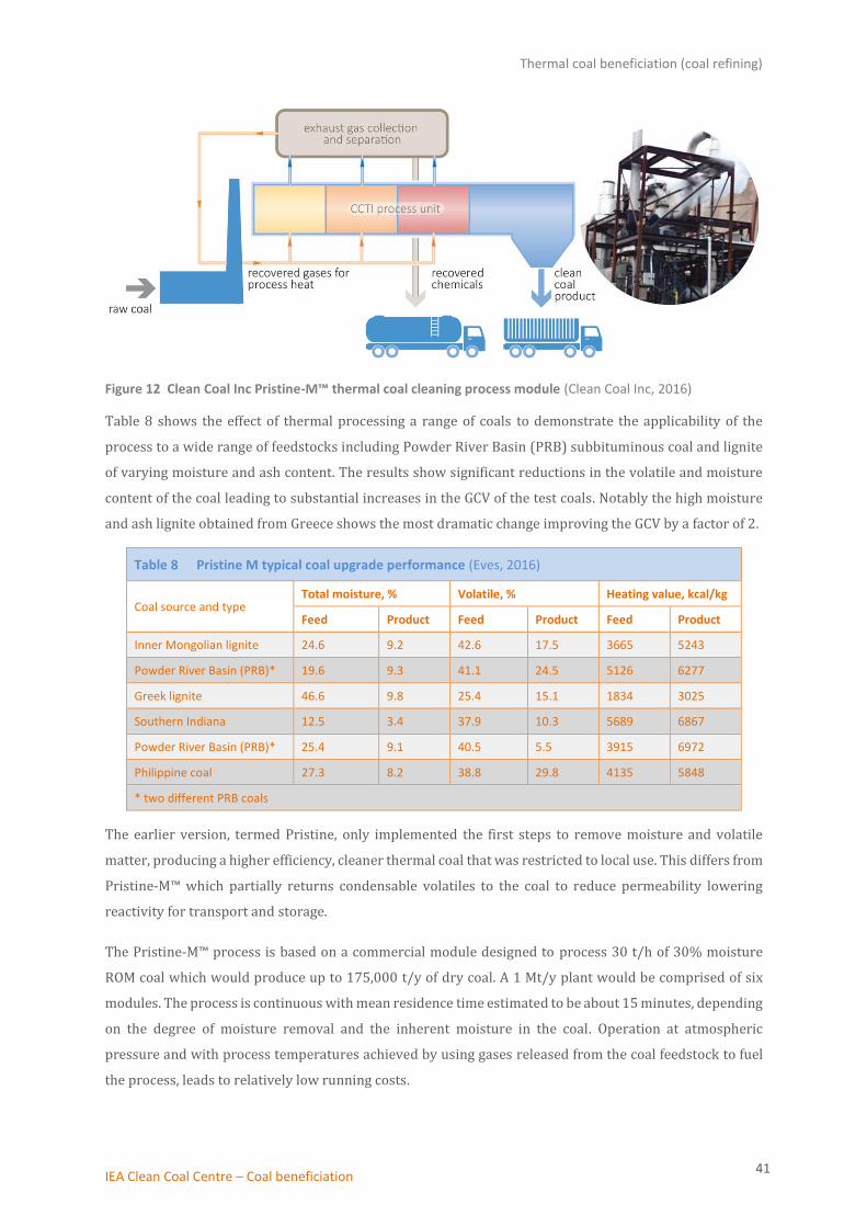
Thermal coal beneficiation (coal refining)
IEA Clean Coal Centre – Coal beneficiation 41
Figure 12 Clean Coal Inc Pristine-M™ thermal coal cleaning process module (Clean Coal Inc, 2016)
Table 8 shows the effect of thermal processing a range of coals to demonstrate the applicability of the
process to a wide range of feedstocks including Powder River Basin (PRB) subbituminous coal and lignite
of varying moisture and ash content. The results show significant reductions in the volatile and moisture
content of the coal leading to substantial increases in the GCV of the test coals. Notably the high moisture
and ash lignite obtained from Greece shows the most dramatic change improving the GCV by a factor of 2.
Table 8 Pristine M typical coal upgrade performance (Eves, 2016)
Coal source and type Total moisture, % Volatile, % Heating value, kcal/kg
Feed Product Feed Product Feed Product
Inner Mongolian lignite 24.6 9.2 42.6 17.5 3665 5243
Powder River Basin (PRB)* 19.6 9.3 41.1 24.5 5126 6277
Greek lignite 46.6 9.8 25.4 15.1 1834 3025
Southern Indiana 12.5 3.4 37.9 10.3 5689 6867
Powder River Basin (PRB)* 25.4 9.1 40.5 5.5 3915 6972
Philippine coal 27.3 8.2 38.8 29.8 4135 5848
* two different PRB coals
The earlier version, termed Pristine, only implemented the first steps to remove moisture and volatile
matter, producing a higher efficiency, cleaner thermal coal that was restricted to local use. This differs from
Pristine-M™ which partially returns condensable volatiles to the coal to reduce permeability lowering
reactivity for transport and storage.
The Pristine-M™ process is based on a commercial module designed to process 30 t/h of 30% moisture
ROM coal which would produce up to 175,000 t/y of dry coal. A 1 Mt/y plant would be comprised of six
modules. The process is continuous with mean residence time estimated to be about 15 minutes, depending
on the degree of moisture removal and the inherent moisture in the coal. Operation at atmospheric
pressure and with process temperatures achieved by using gases released from the coal feedstock to fuel
the process, leads to relatively low running costs.
Thermal coal beneficiation (coal refining)
IEA Clean Coal Centre – Coal beneficiation 42
The existing 3 t/h Pristine-M™ demonstration plant (1/10th scale) is to be relocated from Oklahoma to a
new permanent site to evaluate the process using a wider range of US coals prior to commercial deployment
following recent granting of the US patent (Hunt and others, 2017); a pilot-scale project is utilised to
optimise process conditions specifically for PRB coals, prior to construction of a 30 t/h commercial plant
(Eves, 2016).
In addition, the preparation of fuel for gasification, which has a lower moisture specification, is a promising
application for Pristine-M™ that can provide a uniform low volatile feedstock.
5.2 Thermal cracking and fractionation
Coal pyrolysis has a significant history in the production of liquid coal products, and a novel technology
from Frontier Applied Science combines mild thermal cracking, dewatering and liquid hydrocarbon
fractionation in a single, fluidised bed reactor (McKean, 2014). The FASForm™ or Solid Carbon
Fractionation reactor is initially externally fired by natural gas establishing a rising temperature gradient
as coal descends the column. At steady state, a fuel gas product is generated that provides the energy for
the ongoing process. The feedstock which is preferably low ash-yielding coal is dewatered and the
low-pressure process also removes volatile components to achieve a significant reduction in sulphur,
mercury and nitrogen content. For pulverised coal power generation, the removal of the thermal load of
evaporation and higher boiler efficiency from the upgraded fuel heat content results in improved GHG
characteristics, even though ash components are retained in the fuel.
The low pressure solid-vapour reactive fractionator process will produce approximately 1.5–2 barrels of
liquid products per tonne of coal or lignite, and these are segregated into propane/butane, naphtha,
kerosene and diesel streams which are suitable as refinery feedstocks which can be upgraded to meet fuel
specifications.
Except for the liquid fuels fractionation, the separate features of the process have been demonstrated in
other technologies but not combined in a single, continuously fed reactor. A modular reactor is due to
commence pilot-scale testing in 2017 processing 10 t/d of low ash-yielding feedstock to confirm the
fractionation technology and affirm laboratory trial data on syncrude and dry coal product quality (Pitts,
2017).
5.3 Beneficiation module of a retrofit hybrid gasifier
There are several coal gasification technologies under development that include the Kemper County
transport integrated lignite gasification (TRIG™) technology which commenced electricity generation in
January 2017. Castle-Light’s hybrid gasification technology differs in that it incorporates coal beneficiation
and is intended as an upgrade to retrofit existing under-performing plants.
Re-engineering a pulverised coal boiler to incorporate a gasification reactor fitted with a coal beneficiation
module offers a means to remove sulphur and other contaminants prior to steam generation in the boiler.
The retrofit technology is intended as a replacement for existing boiler firing equipment and to avoid
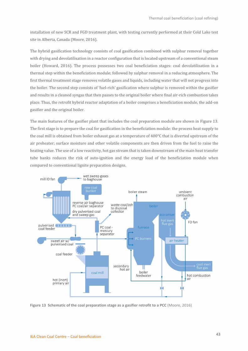
Thermal coal beneficiation (coal refining)
IEA Clean Coal Centre – Coal beneficiation 43
installation of new SCR and FGD treatment plant, with testing currently performed at their Cold Lake test
site in Alberta, Canada (Moore, 2016).
The hybrid gasification technology consists of coal gasification combined with sulphur removal together
with drying and devolatilisation in a reactor configuration that is located upstream of a conventional steam
boiler (Howard, 2016). The process possesses two coal beneficiation stages: coal devolatilisation in a
thermal step within the beneficiation module; followed by sulphur removal in a reducing atmosphere. The
first thermal treatment stage removes volatile gases and liquids, including water that will not progress into
the boiler. The second step consists of ‘fuel-rich’ gasification where sulphur is removed within the gasifier
and results in a cleaned syngas that then passes to the original boiler where final air-rich combustion takes
place. Thus, the retrofit hybrid reactor adaptation of a boiler comprises a beneficiation module, the add-on
gasifier and the original boiler.
The main features of the gasifier plant that includes the coal preparation module are shown in Figure 13.
The first stage is to prepare the coal for gasification in the beneficiation module: the process heat supply to
the coal mill is obtained from boiler exhaust gas at a temperature of 400°C that is diverted upstream of the
air preheater; surface moisture and other volatile components are then driven from the fuel to raise the
heating value. The use of a low reactivity, hot gas stream that is taken downstream of the main heat transfer
tube banks reduces the risk of auto-ignition and the energy load of the beneficiation module when
compared to conventional lignite preparation designs.
Figure 13 Schematic of the coal preparation stage as a gasifier retrofit to a PCC (Moore, 2016)
Thermal coal beneficiation (coal refining)
IEA Clean Coal Centre – Coal beneficiation 44
Following a partial separation of mercury and ash from the coal, the fuel then passes to a baghouse where
volatiles including water vapour are removed before passing the fuel to a pulveriser that feeds coal
combined with limestone to the gasification reactors.
The gasification section of the clean combustion system is intended as a ‘bolt on’ addition with the boiler
retained as a secondary oxidation reactor and steam generator. The gasifier creates ‘fuel-rich’ reaction
conditions through partial combustion of the fuel avoiding the formation of nitric oxides formed from fuel
nitrogen that requires ‘air-rich’ conditions. Injection of limestone intimately mixed with the coal or lignite
feed directly converts sulphur to calcium sulphide in the vitiated air atmosphere, which can then be
removed as a molten slag prior to the main boiler. Thus, the add-on combustor section acts as a sulphur
removal step. The pre-mixing of coal and lime avoids the high reagent consumption of typical dry sorbent
injection DSI technology that is mixing dependent and carried out under milder conditions. The formation
of removable molten calcium sulphide in the gasifier reduces the load on ESP and baghouses located
downstream.
Within the gasifier reactor, nitrogen compounds present in the coal form nitrogen gas rather than nitric
oxide (NO), carbon is partially oxidised to carbon monoxide rather than CO2, while sulphur is converted to
sulphide and removed as part of the molten slag from the reactor base. The reducing atmosphere in the
gasifier section also prevents the formation of SO3, a significant potential source of corrosion in steam
boilers.
Hydrogen is formed from hydrocarbons present in the fuel and from water gas-shift chemistry
equilibrating CO and H2. The syngas product then passes to the boiler where it is partially cooled, the
combustion process is completed with hydrogen oxidised to water and carbon monoxide to carbon dioxide.
Air admission through the original burner ports is staged to control the peak temperature and thermal NOx,
to provide a final gas composition and gas flow rate to match the original boiler design conditions.
In practice, with primary combustion relocated to external gasifiers, the existing boiler is re-configured
with access ports cut through the water wall, while original burner ports are sealed or converted to supply
over fire air to complete combustion.
The emission reduction demonstrated by the combined gasifier – steam boiler, which is an adapted 1940s
stoker furnace, shows performance data comparable to that achieved by a conventional boiler fitted with
an SCR and wFGD treatment plant. Hybrid gasification technology offers an alternative and potentially
lower-cost route to achieve NOx and SOx levels of approximately 100 ppm, when compared to retrofitting
an SCR/wFGD plant. The removal of molten slag prior to the boiler means that the boiler will be maintained
in a much cleaner state and so the technology may be of particular interest for stations currently processing
high sulphur coals with out-of-date emissions control technology.
Current demonstration trials on an adapted Stoker furnace are at 30 MW-scale utilising 15 t/h of hard coal
(2.5% S). The concept is a modular one and so a single gasifier would be suitable for each 100 MW of
capacity. Thus, for a 600 MW scale plant, six gasifiers, each containing four burners and associated with

Thermal coal beneficiation (coal refining)
IEA Clean Coal Centre – Coal beneficiation 45
one coal beneficiation module, would be installed into the base of the pre-existing boiler. The total project
time to modify an existing boiler is estimated at 1.5 to 2 years, with about 4 months required to install the
gasification module, during which time the plant would be offline. The cost of the device is estimated to be
equivalent to a retrofit SCR unit for any given scale of boiler (Moore, 2016).
5.4 Turbulent air and hydrothermal drying
A new process designed by Coomtech based in Kent, UK (Coomtech, 2017) applies high air turbulence to
dry coal or biomass particles. First, coal is supplied to a tube using high velocity low pressure unheated air.
A high-pressure air jet then creates turbulence in the tube stripping off the water. This process is termed
‘surface moisture removal’.
A second thermal process termed inherent moisture removal (IMR) uses uniform heating in a pressurised
chamber to hydrothermally extract moisture contained within coal particles. The continuous hydrothermal
process forms a hydrophobic product that resists moisture re-absorption. The process is currently at the
demonstration stage, evaluating the performance and benefit of the technology on a range of coal
feedstocks that include Columbian coal.

Chemical digestion and bio-oxidation
IEA Clean Coal Centre – Coal beneficiation 46
6 Chemical digestion and bio-oxidation
Chemical pre-treatment can be used to prepare a coal which is ultra-low in ash and sulphur making it an
optimum feedstock for thermal power generation. Sulphur present in ash may be readily removed by
gravity separation techniques, while chemical and biological desulphurisation methods are required to
remove sulphur organically-bound within coal particles. Chemical and biological beneficiation processes
are complex with potentially high energy demand and the resultant increased fuel cost has restricted the
technology to niche applications. In an environmental context, consumption of chemical reagents in the
digestion of coal means that a life-cycle analysis is required to demonstrate the benefits of chemical
cleaning. Given new emission control legislation it is worth revisiting a technology that can remove sulphur
and reduce ash content of coal to below 1% to enable maximum power plant performance.
6.1 Chemical digestion and leaching
Chemical reagents suitable for the desulphurisation of coal have been extensively investigated and
encompass a wide range of powerful oxidation or digestion chemicals that include: calcium fluoride in
sulphuric acid; anthracene oil; sulphuric acid; copper and iron salts; hydrochloric acid; sodium hydroxide
(caustic soda); hypochlorite, potassium permanganate; and N-methyl-2-pyrrolidone (NMP)/ethylene
dioxide mixtures (Sato, 2004; Chaudhary, 1996; Saha, 2013). However, high processing costs have
prevented these technologies from entering general commercial service, and the majority of information
on chemical treatment was obtained more than 20 years ago. More recently, the ultra clean coal (UCC)
caustic process has completed a 10-year demonstration programme in Australia producing ultra-low
sulphur and ash coal to meet the specifications for the direct injection carbon engine (DICE)programme.
The UCC technology is a caustic leach process, an analogue of the Bayer caustic acid process for refining
Bauxite invented in 1887 (International Aluminium Institute, 2012), and a development of the Gravimelt
process (Siwiec, 1994). The UCC pilot facility processed 350 kg/h of coal for the preparation of micronised
carbon slurry fuel. Commissioned in 2002, the plant operated continuously until 2012, and the technology
was acquired by Yancoal of Japan in 2009 (Yancoal, 2016).
The UCC process feed of coarsely milled coal (1.2 to 2 mm diameter) allows sufficient contact of reagents
with the sulphur contained in the coal particles. Earlier chemical leaching technologies specify an optimum
size of less than 500 microns to improve contact between the chemical and the coal. Milling to 500-micron
fineness adds significantly to the processing cost of chemical coal preparation.
The UCC reagents are caustic soda (NaOH) and sulphuric acid; caustic soda is regenerated in the process.
Ash consists mainly of quartz (silica or gangue) which is digested by caustic soda into a soluble form. Other
clays present in the coal particle are dissolved by subsequent sulphuric acid washing, ‘acid soaking’. The
clean coal is recovered by filtration (hydrothermal washing), while the waste products of gypsum and
calcium alumina silicates are recovered for sale or disposal after precipitation from the waste solutions.
This leaching process can reduce ash content of the coal product to below 1%.
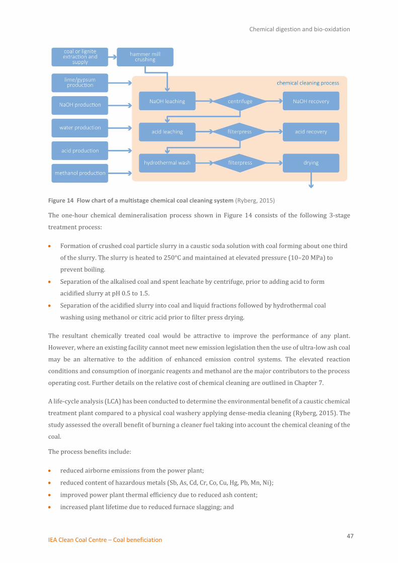
Chemical digestion and bio-oxidation
IEA Clean Coal Centre – Coal beneficiation 47
Figure 14 Flow chart of a multistage chemical coal cleaning system (Ryberg, 2015)
The one-hour chemical demineralisation process shown in Figure 14 consists of the following 3-stage
treatment process:
• Formation of crushed coal particle slurry in a caustic soda solution with coal forming about one third
of the slurry. The slurry is heated to 250°C and maintained at elevated pressure (10–20 MPa) to
prevent boiling.
• Separation of the alkalised coal and spent leachate by centrifuge, prior to adding acid to form
acidified slurry at pH 0.5 to 1.5.
• Separation of the acidified slurry into coal and liquid fractions followed by hydrothermal coal
washing using methanol or citric acid prior to filter press drying.
The resultant chemically treated coal would be attractive to improve the performance of any plant.
However, where an existing facility cannot meet new emission legislation then the use of ultra-low ash coal
may be an alternative to the addition of enhanced emission control systems. The elevated reaction
conditions and consumption of inorganic reagents and methanol are the major contributors to the process
operating cost. Further details on the relative cost of chemical cleaning are outlined in Chapter 7.
A life-cycle analysis (LCA) has been conducted to determine the environmental benefit of a caustic chemical
treatment plant compared to a physical coal washery applying dense-media cleaning (Ryberg, 2015). The
study assessed the overall benefit of burning a cleaner fuel taking into account the chemical cleaning of the
coal.
The process benefits include:
• reduced airborne emissions from the power plant;
• reduced content of hazardous metals (Sb, As, Cd, Cr, Co, Cu, Hg, Pb, Mn, Ni);
• improved power plant thermal efficiency due to reduced ash content;
• increased plant lifetime due to reduced furnace slagging; and

Chemical digestion and bio-oxidation
IEA Clean Coal Centre – Coal beneficiation 48
• reduction of coal transport energy consumption.
The increased environmental demands are identified as:
• additional heat and electricity for chemical cleaning to achieve 250°C;
• chemical production: NaOH, acids (H2SO4 or HCl), methanol CH3OH, and higher water use;
• waste water impact, as partial solvent recovery; and
• overall greenhouse gas emission (furnace efficiency increase offset by energy consumption from
cleaning).
The study assumed a 5% ash content in the coal product as typical from historical data on chemical
leaching; however, this may not represent the full benefit of the UCC process that can deliver ultra–low ash
coal. It was concluded that the chemical process appears less suitable for low ash feedstock, but if the ash
content is substantial and finely distributed throughout the coal matrix, then chemical cleaning is beneficial
(Ryberg, 2015).
The chemical extraction method has the side benefit of reducing the levels of heavy metals, which are of
increasing environmental concern. Most existing PC plants are not fitted with mercury adsorption units
and so removal of mercury and other elements at source would be advantageous.
Production of a chemically cleaned coal possessing <1% ash is one of the two technology options for the
preparation of micronised refined carbon (MRC) fuel for the DICE. The fuel produced by the UCC process
has been successfully tested in a coal slurry modified 1 MWe two-stroke, six-cylinder diesel engine, and
trials on an adapted gas turbine showed ash production at less than 0.2% operating on the MRC slurry fuel
(Dicenet, 2016) (see Chapter 9)
6.1.1 New developments in chemical leaching
The caustic process can produce coals that are low in ash content, but requires relatively high energy input
and produces liquid wastes that may require further treatment. Recent research explores chemical
methods that employ benign reagents which can de-ash and desulphurise coal under mild conditions.
In comparative laboratory trials to test the efficacy of solvents to de-ash coal, a number of potential
reagents were tested: N-methyl-2-pyrrolidone (NMP), furfural, aniline, acetic acid and toluene. Of these
solvents, promising results were obtained using a high ratio of NMP solvent to high-ash coal in a vessel at
ambient pressure and 120°C; this procedure led to an ash reduction of 72% which is significant at these
mild conditions (Saha, 2013).
A desirable feature of NMP is that while it is thermally and chemically stable it is also recyclable and
biodegradable. In this example, recovery of NMP was carried out by mild thermal distillation followed by
hot air drying of the coal dust product.

Chemical digestion and bio-oxidation
IEA Clean Coal Centre – Coal beneficiation 49
As an alternative to fine milling, the action of solvent leaching chemicals may be further enhanced by using
ultrasound for intensive mixing of coal and reagents. Similarly, microwave heating can augment the
breakdown of larger coal particles through steam formation within the particles.
In the power industry, the future of chemical digestion technology will depend on the cost benefit of using
a low ash coal product to achieve performance and emission targets.
6.2 Bio-desulphurisation
An alternative to chemical oxidation or solvent digestion is the use of a biological agent for
bio-depyritisation, where the biocatalyst facilitates oxidation of sulphur. Biological separation was
extensively studied in the 1990’s with significant success achieved with a range of bacteria and fungi,
achieving near complete removal of organic sulphur from coal (Siwiec, 1994). The barrier to technical
implementation has been the long residence times required that may exceed one months’ duration
resulting in the need for a large preparation facility. The intractability of coals possessing interlaced coal
and ash has led to renewed interest in these techniques as an alternative to physical methods.
The proposed mechanism for oxidation of sulphur to sulphate catalysed by the extensively studied
bacterium Thiobacillus ferrooxidans uses an ‘indirect mechanism’, which is then followed by an aeration
step (Prayuenysong, 2002).
The bacterium acts primarily by promoting the oxidation of ferrous iron in the pyrites content of coal. In
addition, the bacteria catalyses the formation of sulphate ions, and also the oxidation of elemental sulphur.
As in the case of chemical treatment, the action of the bacterium is limited by physical access into the
microporous structure of the coal, and so is influenced by the milling size.
The major process parameters identified in the bacteria catalysed desulphurisation, and applicable to the
bio-depyritisation plant depicted in Figure 15, include:
• micro-organism selection;
• particle size (in common with chemical leaching);
• initial pyrite content;
• nutrient composition;
• solution pH – acid alkali adjustment;
• temperature (30–80°C) and residence time;
• aeration (O2/CO2); and
• reactor design (plug flow or multistage).

Chemical digestion and bio-oxidation
IEA Clean Coal Centre – Coal beneficiation 50
Figure 15 Process flowsheet of a plant for coal bio-depyritisation (Klein, 1998)
The plant in Figure 15 shows a multistage bioreactor taking a coal slurry supply from a coal washery to be
treated with a bacterium in a nutrient rich solution containing acid or alkali to adjust pH. Each cell is aerated
to supply oxygen for the process with temperature held between 30°C to 70°C. The remainder of the plant
shows product slurry neutralisation and dewatering. Available operating costs are rather dated and depend
on the plant scale but adjusting for inflation, are considered to lie between 30 US$/t (8000 t/d) to 80 US$/t
(300 t/d) (Klein, 1998).
Although sulphur and ash removal remains an important target, increasingly the focus of research has
shifted to other potentially harmful elements in coal. In a recent research study using a bacterium isolated
and grown from indigenous bacteria in Rajmahal coal, Pseudmonas mndocina strain B6_1, coal samples
were treated for a period of 30 days at ambient conditions. The resultant treated samples show promising
demineralisation activity for trace elements including calcium, potassium, sodium, manganese; selenium,
lead, zinc, and nickel. However, reduction in ash content using this bacterium was limited in these trials,
ranging from only 3% to 7% for the Gopinathpur coal samples (Singh, 2016). The technical challenge is to
reduce the reaction residence time while retaining the metals reduction capability and substantially
reducing the ash content.
In a study investigating fungal leaching from subbituminous coal, the analysis of bio-leached coal treated
by A.niger fungi showed complete removal of sulphur from coal after 10 days exposure (Manoj, 2013).
Biological preparation requires a residence time of many days to effectively treat coal, which compares to
the one hour chemical leaching process. While the plant size must be substantially greater due to slow
bio-kinetics, reagents are less expensive, process conditions are close to ambient, and reagents pose less
Chemical digestion and bio-oxidation
IEA Clean Coal Centre – Coal beneficiation 51
potential impact on the environment. As the need to lower sulphur and heavy metal emission gathers pace
these technologies may offer a means to produce ultra-low sulphur coal.
6.3 Chemical and bio-desulphurisation costs
Chemical cleaning has not been adopted by the thermal coal industry as less expensive physical cleaning
has proved sufficient to meet legislative standards. An analysis of earlier chemical treatment plants dating
to 1980 indicated that the chemical cleaning cost would be of the order of 100 US$/t. This figure is based
on an adjustment of the original costing of about 40 US$/t of coal (an average of several plants priced at
30–50 US$/t) to account for inflation between 1980 and 2016 (Cooper, 2013). Clearly chemical cleaning
costs are substantial and indicate that implementation of a chemical cleaning process is likely to be
reserved for specialist niche applications. As the UCC ultra-low ash coal plant has not been developed to
full commercial scale then it is not possible to evaluate the specific additional cost of this unit.
As for chemical cleaning, while biological methods have the potential to achieve low ash content in coal, the
technology has not been commercially implemented. The energy demand is likely to be lower than for
chemical cleaning, and the reactor would be designed for milder operating conditions close to ambient.
However, the most significant issue is that the process requires large inventories of coal slurry due to the
long reaction time (exceeding ten days), compared to chemical treatment (one hour), which is a scale factor
increase of 240. An estimate of bio-processing cost is likely to exceed 30 US$/t (Klein, 1998), corresponding
to a throughput rate of 8000 t/d.
6.4 Overview of chemical and biological methods
Earlier studies on chemical and biological digestion failed to produce a cost-effective alternative to physical
separation methods. The cost of reagents, waste handling, and additional processing stages to separate
reagents for chemical digestion and the long treatment times required for biological processing made these
technologies less attractive.
However, since that time the regulatory environment, the life-cycle analysis of coal supply, and a focus on
maximising efficient coal plant performance means that these technologies may potentially offer a route to
ultra-low ash coal feedstocks. The gradual decline of coal quality in the intervening period is also relevant;
this is particularly evident in India where the coal type is less tractable to conventional methods and retains
relatively high ash content after treatment.
New research initiatives seek to develop processes which are simpler, more environmentally benign and
which use lower-cost reagents for chemical digestion. Progress on biological methods has shown promising
heavy metals recovery but still needs to reduce processing time to avoid large inventories of coal. These
technologies are the only means to reduce ash levels below 1% which is relevant to certain high value
applications such as DICE.
Lignite drying and demineralisation
IEA Clean Coal Centre – Coal beneficiation 52
7 Lignite drying and demineralisation
Lignite has a low calorific value, high moisture content and often a high ash content. The attractiveness of
indigenous lignite as a feedstock is its ease of extraction via opencast mining and hence it’s relatively low
cost compared to imported coal supplies. Thermal power plants are generally located close to the lignite
mine to avoid transporting low GCV fuel, and lignite is normally milled and burned in its raw state.
Improvement of the fuel quality by drying and removal of ash is one means to meet legislated plant
heat-rate targets; this has the added benefits of improving boiler reliability and reducing plant and effluent
treatment costs.
7.1 Drying technologies
Most lignite boilers currently use raw lignite feed and accept the accompanying loss of efficiency and higher
capital cost associated with the use of low-quality fuel. The presence of water that must be evaporated
using hot furnace gases is a source of inefficiency in lignite plants. Despite numerous research initiatives
the implementation of lignite pre-drying technology has a limited number of full scale commercial
applications due to the additional cost of dryers, and the ensuing need to adjust boiler operation (Zhu,
2012; Dong, 2014; Reid, 2016). However, the changing legislative environment means there is growing
pressure on the industry to adopt fuel drying technology to achieve enhanced plant heat-rate targets, meet
tighter emissions legislation and comply with international COP21 carbon dioxide targets.
In the processing of raw lignite, water evaporation and high-ash heat capacity combine to place a significant
thermal load on lignite power plants which typically utilise high temperature streams diverted from the
boiler to dry the feed. Switching to dry feed reduces the total volume of raw lignite mined and transported
due to improved boiler efficiency. The dried fuel is friable and easily milled, lowering energy use and
maintenance associated with fuel preparation. For new plants, using dried lignite feedstock reduces total
gas flow through the boiler when compared to raw lignite fuel, leading to smaller boilers and lower cost
downstream equipment. For retrofit projects, the installation of new stack gas treatment such as NOx SCR
and mercury abatement units add to the plant parasitic load, making independent options to raise
efficiency much more attractive.
In selecting suitable drying technology, the heat source utilised for drying is critical, as only low-grade or
waste heat streams can provide an efficiency benefit to the plant. A substantial research effort has led to
the development of various lignite drying methods including rotary, mechanical, microwave, high velocity
air, hydrothermal and fluidised bed dryers. They have been reviewed in recent IEA CCC reports (Zhu, 2012;
Dong, 2014). Of these methods, fluidised bed pre-drying technologies have been commercially developed
at full scale and are capable of continuously processing ROM lignite using low-grade heat streams.
Established plants at RWE Technology International (RWE), Germany, and Great River Energy (GRE), USA,
have successfully operated drying systems for over five years, with individual commercial dryers sized at
115–200 t/h. The GRE plant uses two sets of three dryers, with each set supplying 500 t/h of lignite to a
900 MWe plant.
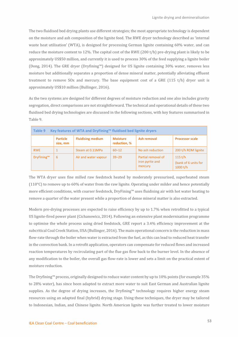
Lignite drying and demineralisation
IEA Clean Coal Centre – Coal beneficiation 53
The two fluidised bed drying plants use different strategies; the most appropriate technology is dependent
on the moisture and ash composition of the lignite feed. The RWE dryer technology described as ‘internal
waste heat utilisation’ (WTA), is designed for processing German lignite containing 60% water, and can
reduce the moisture content to 12%. The capital cost of the RWE (200 t/h) pre-drying plant is likely to be
approximately US$50 million, and currently it is used to process 30% of the feed supplying a lignite boiler
(Dong, 2014). The GRE dryer (Dryfining™) designed for US lignite containing 30% water, removes less
moisture but additionally separates a proportion of dense mineral matter, potentially alleviating effluent
treatment to remove SOx and mercury. The base equipment cost of a GRE (115 t/h) dryer unit is
approximately US$10 million (Bullinger, 2016).
As the two systems are designed for different degrees of moisture reduction and one also includes gravity
segregation, direct comparisons are not straightforward. The technical and operational details of these two
fluidised bed drying technologies are discussed in the following sections, with key features summarised in
Table 9.
Table 9 Key features of WTA and DryFining™ fluidised bed lignite dryers
Particle size, mm
Fluidising medium Moisture reduction, %
Ash removal Processor scale
RWE 1 Steam at 0.11MPa 60–12 No ash reduction 200 t/h ROM lignite
DryFining™ 6 Air and water vapour 39–29 Partial removal of iron pyrite and mercury
115 t/h
(bank of 6 units for 1000 t/h
The WTA dryer uses fine milled raw feedstock heated by moderately pressurised, superheated steam
(110°C) to remove up to 60% of water from the raw lignite. Operating under milder and hence potentially
more efficient conditions, with coarser feedstock, DryFining™ uses fluidising air with hot water heating to
remove a quarter of the water present while a proportion of dense mineral matter is also extracted.
Modern pre-drying processes are expected to raise efficiency by up to 1.7% when retrofitted to a typical
US lignite-fired power plant (Cichanowicz, 2014). Following an extensive plant modernisation programme
to optimise the whole process using dried feedstock, GRE report a 3.4% efficiency improvement at the
subcritical Coal Creek Station, USA (Bullinger, 2016). The main operational concern is the reduction in mass
flow-rate through the boiler when water is extracted from the fuel, as this can lead to reduced heat transfer
in the convection bank. In a retrofit application, operators can compensate for reduced flows and increased
reaction temperatures by recirculating part of the flue gas flow back to the burner level. In the absence of
any modification to the boiler, the overall gas flow-rate is lower and sets a limit on the practical extent of
moisture reduction.
The Dryfining™ process, originally designed to reduce water content by up to 10% points (for example 35%
to 28% water), has since been adapted to extract more water to suit East German and Australian lignite
supplies. As the degree of drying increases, the Dryfining™ technology requires higher energy steam
resources using an adapted final (hybrid) drying stage. Using these techniques, the dryer may be tailored
to Indonesian, Indian, and Chinese lignite. North American lignite was further treated to lower moisture

Lignite drying and demineralisation
IEA Clean Coal Centre – Coal beneficiation 54
levels from 40% to 10% to supply a Siemens dry-feed gasifier. Gasification with combined cycle generation
offers higher efficiency operation on lignite fuel when compared to a conventional power plant, with larger
efficiency gains possible from dried feedstock.
Lignite beneficiation using low energy dryers is a potential means to lower emissions per MWh, which may
be an important measure for power generator groups in the USA seeking to retain low-cost lignite
generation in an overall energy strategy. The most beneficial retrofit improvements to a typical lignite
boiler were assessed to be the upgrading of aged steam turbines refitted into original casings, and the
beneficiation of lignite feed using low energy streams to raise efficiency (Cichanowicz, 2014; Reid, 2016).
Summary of lignite beneficiation
Despite significant research and development initiatives on lignite drying technologies, the majority of
lignite continues to be used in a raw state to avoid the additional cost of processing. However, the need to
raise performance is particularly important in lignite power generation as it is the least efficient of fossil
fuel generators. Suitable drying techniques must use low-energy or waste-heat streams to raise overall
plant efficiency, replacing the use of hot furnace gases.
The prepared lignite fuel is more easily milled which saves energy and the initial removal of inert matter
and water reduces the overall consumption of lignite. Two fluidised bed drying technologies have been
implemented at commercial scale, one treats high moisture lignite, and the other is designed to remove
moisture and ash content by incorporating a gravity segregation module. Unlike hard coal, lignite is not
normally transported over long distances and so these facilities may be best located at the plant to optimise
heat integration. As the industry moves to adopt HELE technologies lignite preparation will become
increasingly important to achieve performance levels and avoid excessive effluent treatment costs.
Micronised fuel for a direct injection carbon engine (DICE)
IEA Clean Coal Centre – Coal beneficiation 55
8 Micronised fuel for a direct injection carbon engine (DICE)
Coal and lignite fuels may be utilised to power a specially-adapted internal combustion engine for flexible
power generation. Replacement of diesel fuel by coal and water mixtures can provide flexible power
production at a fraction of the fuel cost for a comparable diesel-fuelled engine. Historically, coal water
slurry mixtures have been used in conventional burner equipment but attempts to combust these fuels in
an engine proved unsuccessful due to abrasion and deposition in the engine (Kakwani, 1993).
Developments in coal processing have led to a re-formulation of the fuel so that it is in a suitable form to be
directly fed into a diesel engine. Key advances in coal slurry preparation methods involve specific criteria
for fuel viscosity, ash content and particle size.
DICE is being developed to compete with diesel engine generators, support conventional pulverised coal
combustion by offering small-scale flexible power generation and offer an alternative to gas power
generation with long-term cost benefits. DICE may be suited to balance intermittent rapidly fluctuating
renewable energy sources (Wibberley, 2013). DICE has a potential thermal efficiency advantage over
conventional boiler systems due to direct use of combustion energy, avoiding losses associated with heat
transfer within a boiler.
DICE combusts a micronised coal water slurry in a minimally modified, large capacity, diesel engine, such
as an adapted marine engine, to generate electric power, as shown in Figure 16. Individual DICE units,
termed modular generators, could form part of a distributed power network providing grid stability and
security, complementing renewable energy resources. The micronised slurry fuel is intended to replace
diesel, and in appropriate cases, to displace natural gas as the generating fuel. Developers anticipate that
DICE may be installed as a flexible module alongside a conventional USC coal power plant of 500 to
1000 MWe capacity; DICE power may offer incremental generation steps to match demand allowing the
main plant to operate more optimally in a variable power environment.
A 10 MWe marine engine is the currently preferred commercial-scale unit for DICE, shown in Figure 16. It
is operated at moderate revolutions of approximately 500 rpm to allow sufficient residence time to ensure
coal particle burn out. For larger-scale applications, it may be suitable to generate 80 MWe in an engine
consisting of 14 cylinders of 0.956 m bore. Although the MRC fuel is composed of particles suspended in
water, the particles are sufficiently small that the fuel possesses similar characteristics to a fuel oil.

Micronised fuel for a direct injection carbon engine (DICE)
IEA Clean Coal Centre – Coal beneficiation 56
Figure 16 Coal processed to form an ultrafine suspension of coal particles in water for firing in a large capacity diesel engine (Wibberley, 2013)
The technology is currently at the demonstration stage, focused on delivery of successful operation of a
1 MW engine and optimisation of DICE fuel preparation that overcomes technical barriers associated with
feeding particulates. A full history of the development of coal water slurry (CWS) combustion and DICE has
previously been reported by the IEA Clean Coal Centre (Nicol, 2014), and this study will focus on
preparation of the MRC fuel, revisiting suitable feedstocks and considering optimisation of the MRC fuel.
8.1 Suitable coal resources for micronised refined carbon fuel
An ideal coal for the preparation of MRC fuel by physical and/or chemical techniques would be a high
volatility, low-ash coal that is easily milled, that is with a high Hardgrove Grindability Index. However, a
practical approach has been adopted to obtain the best feedstocks for MRC preparation from currently
available resources, of particular relevance to an Australian application:
• Ultrafine coal fractions are normally lost to waste in typical coal washeries, and an MRC preparation
plant could be introduced as a new separation circuit to collect ultrafine coal particles.
• Brown coal in Victoria, Australia possesses a high moisture content but low ash (<4%) and sulphur
(<1%) levels. Lignite is unsuitable for export and local demand for the fuel is in decline, leading to its
availability as a raw feedstock for MRC. Techniques developed for partial lignite drying that increase
coal friability and lower ash content may also be of interest for these feedstocks (Section 7.1).
• Coal tailings are a waste stream that consists of ultrafine coal mixed with ash. MRC preparation is one
potential solution to reduce accumulation of tailings ponds formed as a result of preparing coal for
export. The coal in tailings is already in a finely divided form and may be tractable to MRC physical
separation techniques.
The coal tailings application is especially topical given the vast accumulation of tailings in some regions and
the developing environmental legislation relevant to coal preparation and tailings ponds (Szczepanski,
2012).
An important attribute in selecting suitable coals is its mineral composition. The abrasion by particulates
in the injection system and combustion cylinder represent the most practical difference between the
Micronised fuel for a direct injection carbon engine (DICE)
IEA Clean Coal Centre – Coal beneficiation 57
combustion of diesel and MRC fuel. Coals possessing a lower content of harder minerals such as quartz and
pyrite are preferred for this application.
Considering regions where coal use is set to expand, the Indian Gondwana coals are among the most
difficult to prepare as there is a fine matrix of ash interspersed with coal particles. Bespoke preparation
plants for these high ash coals to remove a portion of the ash are being developed for standard pulverised
coal furnaces. Although a relatively expensive option, fine milling to enable the liberation of coal particles
could form part of an MRC production plant, producing a higher value fuel capable of replacing diesel engine
generation which remains prevalent in India.
8.1.1 Coal grain analysis method
The method developed to assess whether a coal or coal tailings can be successfully processed to form MRC
fuels is termed coal grain analysis (CGA) and examines coal particle distribution in a sample. Standard coal
analysis focuses on the physical and chemical properties of coal samples:
• elemental composition (C, H, S, N, O);
• sulphur forms (chemically bonded sulphide/sulphate/organic sulphur);
• moisture;
• ash and ash fusibility;
• volatile and carbonaceous content;
• trace element analysis; and
• density distribution which affects gravity separation methods (Speight, 2015).
These analyses are relevant to assess coals for MRC, but the specific particle petrography analysis
developed for an MRC feedstock determines the mineral distribution and maceral composition within coal
samples. The vitrinite/inertite/liptinite maceral content influences the volatilisation of coal within a piston
engine, and the mineral/maceral distribution affects the particle surface properties and hence the efficacy
of micro-flotation separation methods.
The CGA optical microscopic imaging technique provides an assessment of the coal liberation efficiency
and potential yield from a given sample. From a benchmark of coal samples the lowest potential ash value
can be determined using Jameson cell preparation, assuming all entrained minerals are removed from the
coal, and the likely fuel yield at a given ash removal level. The technique is most accurate for ultrafine
milled material where there is the maximum access to the mineral content of the coal (O’Brien, 2011). The
analysis thus provides an assessment of the yield and cost of MRC preparation from any coal resource.
8.2 Preparation of MRC fuel
The preparation of MRC fuel requires most of the ash to be removed from the coal which may be achieved
by physical processing methods employing micro-flotation techniques, by chemical preparation methods,
or by separation of fine coal particulates based upon coal chemical properties such as
hydrophobic-hydrophilic 2-liquid separation.

Micronised fuel for a direct injection carbon engine (DICE)
IEA Clean Coal Centre – Coal beneficiation 58
Ideally the mineral content of fuels suitable for MRC would approach less than 2% on a dry coal basis
(Arthur D Little Inc, 1995), an important fuel attribute when intended for use in combustion engine
equipment normally fuelled by low viscosity liquids such as diesel. Chemical cleaning, discussed in
Chapter 6, can achieve near-complete removal of ash but is relatively expensive due to multistage
processing and the consumption of up to three chemical reagents. In addition to the high cost of chemical
leaching the process has a significant environmental impact due to chemical production, energy use and
liquid waste disposal.
Figure 17 illustrates the processing cost benefit of applying a mineral target of 2% dry basis ash content
for MRC that enables physical separation methods.
Figure 17 Comparison of the processing cost as a function of ash content (dry basis) dependent on ROM coal beneficiation techniques (Wibberley, 2013)
The cost competitiveness of MRC fuel may be improved by setting a target of 2% ash that is shown to
achieve sufficiently low abrasion and deposition characteristics. Chemical cleaning of the coal remains the
most technically effective solution to minimise mineral content and remains an option for replacement of
more expensive diesel fuel. The cost of chemical cleaning is shown to be a factor of five times higher than
physical preparation of fuel that can achieve 2% ash content.
The preferred MRC fuel production method for DICE is to feed fine particles, either from ultrafine milling,
or derived from the spiral circuit of a CPP plant, to a Jameson cell to separate the coal from ash. The method
has been successfully demonstrated and is detailed in Section 8.2.1.
A new hydrophobic-hydrophilic 2-liquid separation method HHS (see Section 4.3) may also be applicable.
The technique depends on hydrophobicity differences and initial trial data indicate that an ash content of
less than 2% dry basis is achievable, which would make this process potentially suitable for MRC
preparation (Gupta, 2016).
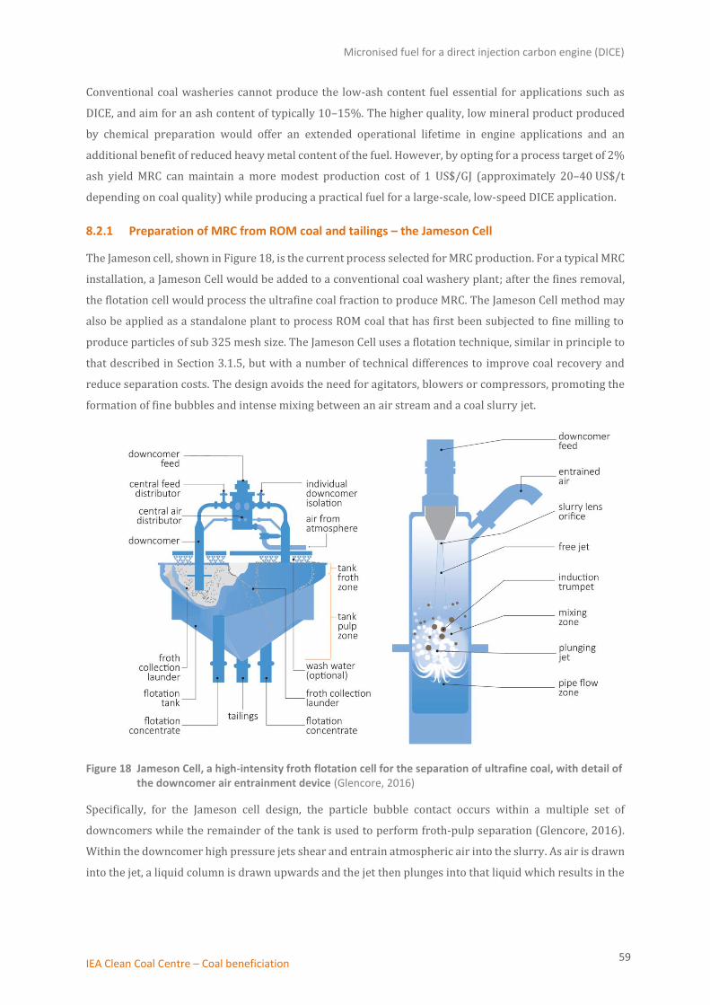
Micronised fuel for a direct injection carbon engine (DICE)
IEA Clean Coal Centre – Coal beneficiation 59
Conventional coal washeries cannot produce the low-ash content fuel essential for applications such as
DICE, and aim for an ash content of typically 10–15%. The higher quality, low mineral product produced
by chemical preparation would offer an extended operational lifetime in engine applications and an
additional benefit of reduced heavy metal content of the fuel. However, by opting for a process target of 2%
ash yield MRC can maintain a more modest production cost of 1 US$/GJ (approximately 20–40 US$/t
depending on coal quality) while producing a practical fuel for a large-scale, low-speed DICE application.
8.2.1 Preparation of MRC from ROM coal and tailings – the Jameson Cell
The Jameson cell, shown in Figure 18, is the current process selected for MRC production. For a typical MRC
installation, a Jameson Cell would be added to a conventional coal washery plant; after the fines removal,
the flotation cell would process the ultrafine coal fraction to produce MRC. The Jameson Cell method may
also be applied as a standalone plant to process ROM coal that has first been subjected to fine milling to
produce particles of sub 325 mesh size. The Jameson Cell uses a flotation technique, similar in principle to
that described in Section 3.1.5, but with a number of technical differences to improve coal recovery and
reduce separation costs. The design avoids the need for agitators, blowers or compressors, promoting the
formation of fine bubbles and intense mixing between an air stream and a coal slurry jet.
Figure 18 Jameson Cell, a high-intensity froth flotation cell for the separation of ultrafine coal, with detail of the downcomer air entrainment device (Glencore, 2016)
Specifically, for the Jameson cell design, the particle bubble contact occurs within a multiple set of
downcomers while the remainder of the tank is used to perform froth-pulp separation (Glencore, 2016).
Within the downcomer high pressure jets shear and entrain atmospheric air into the slurry. As air is drawn
into the jet, a liquid column is drawn upwards and the jet then plunges into that liquid which results in the

Micronised fuel for a direct injection carbon engine (DICE)
IEA Clean Coal Centre – Coal beneficiation 60
formation of fine air bubbles that contact with the coal and ash particles. The various zones in the
‘downcomer’, as depicted in Figure 21, include:
• a free jet entrains air into the slurry;
• an induction trumpet channels air into the slurry jet base;
• a plunging jet shears air into fine bubbles;
• a mixing zone of recirculating eddies; and
• finally, a pipe flow zone, a downward moving fluidised bed.
The high interfacial surface area and intense mixing promotes particle attachment to the air bubbles,
raising the efficiency of ultrafine coal recovery. A recycle system in the Jameson cell enables multiple passes
for rejects, reducing waste and is essential where the initial feed has high ash content. This feature is of
specific relevance to the handling of tailings feedstock.
The process yields an MRC fuel with particle size of approximately 10 microns, and an ash content of less
than 2%. The final coal content of the slurry product is set depending on actual mean particle size and the
intended application for the slurry, but higher levels exceeding 60 wt% carbon are targeted for DICE
applications.
8.2.2 Viscosity modification – MRC fuel transport, storage and atomisation
Diesel or heavy fuel oil are homogenous liquids and can be stored indefinitely. Coal water fuels are more
sensitive as there is a tendency for the slurry to destabilise and form sludge. Other fuel handling issues
include the abrasive wear of pumps, instability of the stored fuel and possibility of blockages. In practice
these problems are prevented by recirculating and stirring the fuel, and by the addition of additives to
disperse and stabilise the fuel leading to somewhat more complex formulations.
In a conventional fuel, low viscosity results in finer atomisation which promotes efficient combustion and
leads to lower particulate emissions. Diesel fuel atomisation shows similar atomisation characteristics to
water, with low viscosity leading to small droplets in narrow size distributions, optimised in the latest high-
pressure fuel injector designs (Jankowski, 2002). Comparable atomisation of heavy fuel oil would result in
a larger Sauter mean diameter droplet size due to the higher viscosity of the fuel, producing a wider size
range distribution and leading to increased soot levels. Thus, it would be expected that a low viscosity MRC
fuel would be preferred for diesel engine applications. However, researchers report that a somewhat higher
viscosity is preferable for fuel handling and atomisation in diesel injectors, compared to the low viscosity
fuel of typical commercial coal slurry burners (Wibberley and Dryer, 2015).
Where the MRC fuel is prepared to meet low viscosity criteria then the coal content of the fuel is reduced
to less than 50% carbon, and storage of the fuel requires greater use of additives such as polystyrene
sulphonate, to maintain the dispersal of coal particles in water. Low viscosity coal slurry fuels are also
prone to destabilisation, particularly at low loading levels, requiring addition of compounds such as
xanthan gum, accompanied by continuous recirculation to prevent sludge formation. Allowing a higher
viscosity alleviates these problematic issues found in coal slurry fuels, and permits higher coal content in

Micronised fuel for a direct injection carbon engine (DICE)
IEA Clean Coal Centre – Coal beneficiation 61
the slurry while minimising the additives package. Improved transport and storage properties for MRC fuel
is a key attribute for commercial application of the technology.
Higher viscosity was expected to impair combustion of the MRC fuel, but in practice this has not been the
case; the better than expected performance was attributed to greater shear forces applied in diesel
injectors compared to typical coal water slurry (CWS) fuel injectors (Wibberley and Dryer, 2015). The high
shear rates exceeding 750/s of diesel injectors permits the viscosity to increase to about 1 Pa/s, while
conventional CWS applications require a viscosity of approximately 0.3 Pa/s; the high shear rate
counteracts higher viscosity in the atomisation process.
The impact of adopting higher viscosity MRC fuel on particulate combustion has proved to be minimal, and
the slurry coal content can be increased from 45 wt% to at least 60 wt% or higher, dependent on the mean
particle size in the slurry. In addition to the benefit to fuel stability discussed above, the higher coal content
results in higher thermal efficiency, of critical importance where the environmental performance of the fuel
is closely scrutinised. The MRC fuel has the potential for lower NOx emissions than diesel due to the
suppression of peak temperatures by the presence of water, but clearly particulate emissions will be higher
due to the initial ash content of the fuel.
8.2.3 Abrasion and erosion
Micronised refined carbon fuels are designed to overcome the abrasive properties of conventional coal
water slurry (CWS) fuels. MRC fuel is processed to achieve a low mineral content, with sulphur and mineral
content at less than 1/10th of a typical prepared coal and coal particles in the micron size scale. The
particulate size in CWS is typically 75 microns which is unsuitable for a diesel engine design, whereas for
MRC the particulate size is less than 10 microns. The MRC water content is typically 25% to 40% and
contains an additives package to modify the fuel rheology consisting of dispersants, surfactants,
neutralisers and stabilisers forming up to 1% of the fuel (Williams, 2013).
The practical concern in using CWS fuel is the potential deterioration of the diesel engine combustor parts;
injector erosion impairs atomisation leading to increased soot production, and piston wear caused by
particulate accumulation can eventually lead to jamming of the piston ring. Although superior to CWS due
to the finer particulate size, MRC is less effective than diesel liquid fuels at lubrication of injection parts;
development has focused on replacing vulnerable materials with alumina or tungsten carbide injector parts,
the main engine alteration required to use MRC instead of diesel fuel.
Accumulation of particles on the walls within the engine cylinder can lead to excessive erosion and it is
likely that MRC fuels will produce more abrasive particles than diesel fuels. Engines fuelled by diesel
produce hollow particulates derived from the fuel, termed cenospheres (Williams, 2013). The size of these
carbon rich particles varies but can be up to 3% of the original diesel fuel droplet mass, an accumulation of
particles can cause the size to increase to 10% (Jankowski, 2002). The micronised fuel droplet is intended
to be less than 10 microns in diameter and hence of comparable size to some particles produced from diesel.
However, it is the hardness of the particles which is the most significant property, and the mineral content
Micronised fuel for a direct injection carbon engine (DICE)
IEA Clean Coal Centre – Coal beneficiation 62
of these particles means they will be more abrasive. Tests show that a modified diesel engine can accept
MRC particulates, even though these would be more numerous and abrasive than in petroleum fuels.
8.3 MRC fuel summary
The DICE requires a coal slurry fuel of low ash content, and the replacement of certain engine injection
components to avoid excessive wear. Suitable coal supplies can be assessed using a bespoke coal grain
analysis method which can predict the efficacy and cost of the separation technique. The technology is
currently sourcing feedstock from existing CPP fine coal circuits or from processing waste tailings streams.
Adoption of an r ash content specification of 2% enables the use of a physical separation method rather
than the earlier, costlier chemical digestion technique.
The 2% ash yield specification showed promise in early trials, and when combined with a higher viscosity
formulation resulted in improved fuel storage and handling. A long-term proving trial in a large-scale
engine is needed to demonstrate the applicability of a 2% mineral content. The effluent from the engine
should show a reduction in NO content compared to diesel fuel due to effect of water suppressing peak
temperatures, however, the increase in ash content of the revised fuel specification will result in a
requirement for effluent dust control.
The technology competes with natural gas turbines to offer a flexible power product of typically
10 MW-scale as an add-on to conventional power plants to rapidly respond to power fluctuation from
intermittent alternative sources such as wind. The economics of the DICE is based upon the stable pricing
of coal feedstocks. In Asian markets the current low natural gas price reduces the commercial benefit of the
DICE technology, but the price of natural gas is historically highly variable. The DICE can achieve efficiency
comparable to diesel fuelled engines, may exceed the potential efficiency of subcritical power plants, and
competes favourably with distributed diesel electric generation.

Conclusions
IEA Clean Coal Centre – Coal beneficiation 63
9 Conclusions
In response to tightening environmental legislation thermal coal plants are required to update emissions
control treatment. Improving the quality of coal feedstock reduces pollutant emissions at source and
improves boiler performance. The use of beneficiated coals is one option available to operators to achieve
greenhouse gas emission targets. High quality coals provide the optimal feedstock for HELE thermal coal
plants that are sensitive to coal characteristics; treated coals may offer an alternative to introducing
emission control systems on outmoded plants.
Preparation of coal to meet international trading standards covering ash, moisture and energy content is
long established, but the actual quality of coal fed to thermal stations has often been of lower quality based
on inferior indigenous supplies. There is a general global trend of using inferior feedstock, due to the
reduced availability of quality coal. Generation using low quality, low sulphur coal means that installation
of enhanced FGD systems can be postponed although impaired reliability and thermal performance may
have to be accepted. This strategy is incompatible with new legislative limits and raising coal quality may
now be a more practicable means to meet performance and environmental targets.
New coal preparation plants are planned in developing countries which intend to significantly increase
their thermal power capacity. Coarse and small coal beneficiation is generally practiced and new
developments in coal washeries are focused on fine and ultrafine coal treatment to reduce waste, and the
tailoring of treatment technologies to coals that possess finely interspersed mineral and carbon content.
Dry separation of coal using riffling tables is taking an increasing share of the market due to concerns over
water shortages. Although potentially less expensive, dry treatment is also less efficient than dense-media
technologies. Recent developments show that dry air table methods can be extended to include small coal
sizes, and there is an option to use wet methods in an adjoining circuit dedicated to recovering fine
particulates.
The environmental impact from washery tailings ponds necessitates new solutions to reduce waste
streams. In the dewatering stage, centrifuges have extended the range of recoverable ultrafine coal
particles, and increased application of froth flotation in thermal coal preparation improves coal recovery
and reduces the quantity of waste to be disposed. A new method employing the hydrophobic property of
coal particles, hydrophobic-hydrophilic 2-liquid separation (HHS) seems to be an efficient means to recover
fine coal particles and achieve low sulphur specifications. These technologies may have applications in
reprocessing existing wet waste contained in slurry coal ponds.
Coking coals are prepared at high temperature, but new thermal coal refining methods operating at
intermediate temperatures of up to 450°C may offer a superior, cleaner coal compared to that prepared by
physical methods. This thermal treatment can substantially reduce pollutants such as sulphur and mercury,
and form stable and uniform coal supplies permitting more optimum boiler operation.
Conclusions
IEA Clean Coal Centre – Coal beneficiation 64
The chemical treatment of coal has proved to be more expensive than physical methods, and there are
concerns over control of wastes and energy consumption. Recent research on chemical digestion seeks to
employ benign leaching agents that are effective under moderate processing conditions. Chemical cleaning
provides a method to produce ultra-low sulphur and ash content that would be of interest in specialist,
higher value applications. Chemical treatments are most suitable when processing fine or ultrafine coals
where the coal particles can be accessed more easily to leach out mineral components. The comparable bio-
oxidation of coals has yet to gain commercial acceptance due to the long reactor residence times, although
the moderate processing conditions potentially mean that biological methods may be able to compete
economically with chemical leaching.
Conventional dense-media and dry coal preparation costs vary from 1 to 10 US$/t depending on the degree
of preparation which ranges from minimal sorting through to total coal cleaning using froth floatation
techniques. The cost of chemical digestion or bio-oxidation is higher but offers a route to ultra-low ash
content of less than 1 wt%, with optimised physical methods capable of achieving an ash content of 2 wt%.
Lignite coal processing developments have centred on drying methods as the water and ash levels in lignite
affect the overall performance of a station. Plants have operated at commercial scale using fluidised bed
reactors that harness waste energy streams. In addition to drying lignite, these systems can be configured
to remove dense mineral matter. These methods are increasingly relevant to improve boiler efficiency and
reduce sulphur and mercury emissions enabling efficient power generation from low cost, locally available
fuel. Lignite gasification plants, striving to maximise efficiency, have much to gain from using beneficiated
lignite.
DICE uses a coal water slurry fuel that may have the potential to offer a flexible power option which can
replace diesel power generation; the rapid response method is especially suited to balance the output from
intermittent renewable energy resources. A coal slurry fuel has been formulated that is suitable for use in
a minimally modified marine diesel engine, equipped with dust control measures. A Jameson flotation cell
is the preferred fuel production method separating coal drawn from the fine fraction of a coal preparation
plant, or alternatively from a tailings waste stream.
Coal beneficiation is a mature technology that is being re-examined in response to new legislative initiatives.
Currently, coal preparation plants must tackle the issues of water use, ash content, coal recovery and liquid
waste. Legislators are demanding higher efficiency and lower emissions from coal power generation. The
industry has responded primarily by improving boiler technology and adding more sophisticated effluent
treatment. However, improving the quality of coal at source alleviates a number of reliability issues,
reduces the energy associated with coal transport, reduces the amount of coal processed in the plant, and
eases effluent treatment and waste disposal. It may be as cost effective to improve the quality of coal as it
is to introduce new technologies.
For an existing power plant, where the technology cannot easily be modified, improving fuel quality is the
most significant option available to raise performance. This is particularly relevant where new emission
control equipment is required and hence there is additional plant parasitic energy demand. Feedstock

Conclusions
IEA Clean Coal Centre – Coal beneficiation 65
strategies need to reduce both water and ash content, but technologies that remove other contaminants
such as heavy metals are gaining importance. Where there is a desire to use low quality indigenous
feedstock which impairs power plant performance, the installation of new coal beneficiation facilities could
approach international performance standards.
References
IEA Clean Coal Centre – Coal beneficiation 66
10 References
Adams D (2016) Coal after Paris. World Coal; 25(7); 10 (Jul 2016)
Allair (2016) Pneumatic Allair jig – efficient and eco-sensitive. Allmineral. Available at: http://www.allmineral.com/en/loesungen/produkte/allair/ Duisburg, Germany, Allmineral, vp (accessed 18 Oct 2016)
Altindelep Z, Bayat O (2014) Evaluation of Mayer curve validity on the TKI-GELI coal at the washery plant (Mugla, Turkey). Paper presented at: 14th Mineral processing symposium, Kuşadasi, Turkey, 15-17 Oct 2014. 6 pp (Oct 2014)
Arthur D Little Inc (1995) Coal-fueled diesel system for stationary power applications – Technology development. Available at: https://www.osti.gov/scitech/biblio/179214 DOE/MC/25124—5060, Springfield, VA, USA, National Technical Information Service, vp (1995)
Asmatulu R, Luttrell G H, Yoon R H (2005) Dewatering of fine coal using hyperbaric centrifugation. Coal Preparation; 25; 117-127 (2005)
Barnes I (2016) The prospects for HELE power plant uptake in India. CCC/271 London, UK, IEA Clean Coal Centre, 54 pp (Nov 2016)
Baruya P (2012) Losses in the coal supply chain. CCC/212, London, UK, IEA Clean Coal Centre, 66 pp (Dec 2012)
Baruya P (2016) Fuelling increased electricity production in the emerging economies of Asia. Cornerstone; 4(1); 4-9 (Spr 2016)
Bayar T (2016) Active Energy Coalswitch + Biomass for energy (BFE) fuels. Power Engineering International; 24(2);20-22 (Feb 2016)
Bethell P J, Arnold B J (2003) Comparing a two-stage spiral to two stages of spirals for fine coal. In: Advances in gravity concentration. Littleton, CO, USA, Society for Mining, Metallurgy and Exploration, Inc, pp 107-114 (2003)
Bethell P J, Barbee C J (2007) Today’s coal preparation plant: a global perspective in designing the coal preparation plant of the future. In: Designing the coal preparation plant of the future. Littleton, CO, USA, Society for Mining, Metallurgy and Exploration, Inc, pp 9-20 (2007)
Bhagwat S B (2009) Estimation of coal-cleaning costs: spreadsheet-based interactive software for use in the estimation of economically recoverable coal. Available at: pubs.usgs.gov/pp/1625f/downloads/ChapterG.pdf US Geological Survey Professional Paper 1625-F, Reston, VA, USA, US Geological Survey, vp (2009)
Brooks P, Waugh B, Clark K, Weir S (2004) Process for demineralising coal. WO Patent 2004/039927, Geneva, Switzerland, World Intellectual Property Organisation, vp (2004)
Bulatovic S M (2014) Handbook of flotation reagents: chemistry, theory and practice, flotation of sulphide ores. Amsterdam, Netherlands, Elsevier Science, Vol 1, 458 pp (2014)
Carpenter A (2015) Water availability and policies for the coal power sector. CCC/256, London, UK, IEA Clean Coal Centre,102 pp (Aug 2015)
Carpenter A (2016) Potential water sources for coal-fired power plants. CCC/266, London, UK, IEA Clean Coal Centre, 99 pp (Jun 2016)
Choudhury S B, Brahmachari B B, Dwivedi S R, Roy A K, Dasgupta P K, Chakra Borty M, Haque R (1996) Solvent-refined coal from high ash non-coking coal & washery middling for use in metallurgical coke making. Part 1 Production, testing and characterisation. Dhanbad, Bihar, India, Central Fuel Research Institute, vp (Jan 1996
References
IEA Clean Coal Centre – Coal beneficiation 67
Clean Coal Inc (2016) Clean Coal Technologies announces the successful results of their Pristine M technology commissioning. Available at: http://cleancoaltechnologiesinc.com/technology/pristine-m/ New York, NY, USA, Clean Coal Technologies, Inc, 1 pp (Feb 2016)
CMPDI (2015) Pre-feasibility report for setting up of Kusmunda Washery (25.0 MTY) in Kusmunda area: South Eastern Coalfields Ltd. Available at: http://environmentclearance.nic.in/writereaddata/Online/TOR/0_0_08_Aug_2015_1255254531Prefeasibilityreport.pdf Ranchi, India Central Mine Planning & Design Institute, 54 pp (Aug 2015)
Colorado Air Pollution Control (1998) Coal preparation plants. 40 CFR Part 60Y. Available from: https://www.colorado.gov/pacific/sites/default/files/AP_Coal-Preparation-Plants-Guidance-Document-and-Checklist.pdf Denver, CO, USA, Air Pollution Control Division, 51 pp (Jun 1998)
Coomtech (2017) Surface (SMR) and inherent (IMR) moisture removal. Available from: www.coomtechltd.com/index.php/technology/ Sandwich, UK, Coomtech, vp (accessed 22 Mar 2017)
Cooper B (2013) The science and technology of coal and coal utilization. New York, NY, USA, Springer Science and Business Media, 66 pp (Nov 2013)
Couch G (2002) Coal upgrading to reduce CO2 emission. CCC/67, London, UK, IEA Clean Coal Centre,72 pp (Oct 2002)
CWP (2016) Heavy media coal washery plant: 450 t/h plant – Mugla Turkey. Available from: http://www.cwp.com.tr/en/references.aspx?id=1 Cigli-Izmir, Turkey, CWP, 1 pp (accessed 22 Oct 2016)
Darling P (2011) Froth flotation – fundamental principles. In: SME Mining Engineer Handbook 3rd Edition. Amsterdam, Netherlands, Knovel, Elsevier. 1840 pp (2011)
D’Aprile A, Davide M (2016) Climate policy highlights: China’s 13th Five-Year Plan and recent developments. Available from: http://www.iccgov.org/wp-content/uploads/2016/04/2016.04.14_Seminar_Davide_DAprile.pdf Venice, Italy, International Centre for Climate Governance, 24 pp (Apr 2016)
Dicenet (2016) Recent research on DICE. Available from: http://dice-net.org/index.php/technology/recent-r-and-d, Melbourne, VIC, Australia, Dice Development Network, vp (accessed 11 Aug 2016)
Dipu D (2016) Coal washing needs a spur. Available from: http://www.vccircle.com/infracircle/coal-washing-needs-spur/ India, Infra-circle, News Corp VC Circle, 2 pp (Aug 2016)
Dong N (2014) Techno-economics of modern pre-drying technologies for lignite fired power plants. CCC/241, London, UK, IEA Clean Coal Centre, 46 pp (Sep 2014)
Eck S W (2007) Coal crushing considerations. In: Designing the coal preparation plant of the future. Littleton, CO, USA. Society of Mining Metallurgy and Exploration, pp 33-41 (30 Sep 2007)
EPA (2015) Regulatory impact analysis for the Clean Power Plan Final Rule EPA-452/R-15-003. Available at: http://www.epa.gov/cleanpowerplan/clean-power-plan-proposed-federal-plan-regulatory-impact-analysis Columbus, OH, USA, Environmental Protection Agency, 2 pp (Aug 2015)
Eraydin K M, Roach J C (2016) Chemical enhancement. World Coal; 25(3), 69 (Mar 2016)
Eriez (2016) Eriez Flotation Division: Column flotation. Available from: https://www.eriezflotation.com/flotation/column-flotation/ Caerphilly, UK, Eriez Magnetics Europe Ltd, 1 pp (accessed 18 Oct 2016)
Eves R (2016) Clean green and pristine, World Coal; 25(7); 47-52 (Jul 2016)
FGX (2016) FGX separation technology. Available from: http://www.fgxseptech.com/about/ Lexington, KY, USA, FGX Separation Technology, 3 pp (accessed 22 Oct 2016)

References
IEA Clean Coal Centre – Coal beneficiation 68
FLSmidth (2017a) Coal spiral concentrator. Available from: http://www.flsmidth.com/en-US/Industries/Categories/Products/Classification/Spirals/Coal+Spiral+ Concentrator/Coal+Spiral+Concentrator, Bethlehem, PA, USA, FLSmidth Inc 2 pp (accessed 4 Apr 2017)
FLSmidth (2017b) Flotation technology brochure. Available from: http://www.flsmidth.com/~/media/PDF%20Files/Liquid-Solid%20Separation/Flotation/FlotationTechnology_brochure.ashx, Bethlehem, PA, USA, FLSmidth Inc, 16 pp (accessed 4 Apr 2017)
Galvin K P, Callen A, Zhou J (2005) Performance of the reflux classifier for gravity separation at full scale. Minerals Engineering, 18, 19-24 (2005)
Glencore (2016) Jameson cell principles. Available from: http://www.jamesoncell.com/EN/Pages/default.aspx. Brisbane, Qld, Australia, Glencore Technology, vp (accessed 1 Nov 2016)
globalCOAL (2016) Internationally traded coal specifications (SCoTA). Available from: https://www.globalcoal.com/scota/specifications.cfm London, UK, globalCOAL, vp (accessed 24 May 2016)
Goyal P (2016) India to stop thermal coal imports; save Rs 40,000 crore. Available from: http://economictimes.indiatimes.com/industry/indl-goods/svs/metals-mining/india-to-stop-thermal-coal-imports-save-rs-40000-crore/articleshow/51839241.cms Mumbai, India, The Economic Times, 2 pp (15 Apr 2016)
Grewal I (nd) Introduction to Mineral Processing. Available from: http://met-solvelabs.com/library/articles/mineral-processing-introduction Langley, BC, Canada, Met-solve Laboratories Inc, 12 pp (accessed 11 Oct 2016)
Gupta N (2016) Evaluation of pneumatic inclined deck separator for high-ash Indian coals. International Journal of Coal Science & Technology; 3(2);198–205 (Jun 2016)
Gupta N, Li B, Luttrell G, Yoon R H, Bratton B, Reyher, J (2016) Hydrophobic–hydrophilic separation (HHS) process for the recovery and dewatering of ultrafine coal. Presented at: SME annual meeting: Coal Prep, Louisville, KY, USA, 25-27 Apr 2016. 6 pp (2016). Available at: http://www.mineralsrefining.com/hhs-technology/
Hatt R (1990) Influence of coal quality and boiler operating conditions on slagging of utility boilers. Available from: http://coalcombustion.com/PDF%20Files/UEFInfluenceSlag03.pdf 9 pp (1990)
Holden E, Kuckro R (2016) E&E’s power plan hub Texas. Washington DC, USA, Environment and Energy Publishing (E&E) 2 pp (13 May 2016). Available at: http://www.eenews.net/interactive/clean_power_plan/states/texas (accessed 24 May 2016)
Honaker R, Luttrell G H (2007) Development of an advanced deshaling technology to improve the energy efficiency of coal handling, processing, and utilisation operation. US Department of Energy Report No. DE-FC26-05NT42501, Lexington, KY, US University of Kentucky Research Foundation, 39 pp (2007) Available at: http://sciencepolicy.colorado.edu/students/envs_5720/honaker_2010.pdf
Hunt L, Paul A D, Mendez F J, Garcia A (2017) Process for treating coal. US Patent 9476003, USA, US Patent and Trademark Office, 83 pp (2017)
IGU (2016) Wholesale gas price survey: a global review of price formation mechanisms 2005 to 2015, 2016 Edition. Available from: file:///C:/Users/Ian/OneDrive/IEA%20coal%20benefication/DICE%20fuel%20prep%20fines%20treatment/IGU_WholeSaleGasPrice_Survey0509_2016.pdf Fornebu, Norway, International Gas Union, 62 pp (2016)
IEA (2015a) IEA World Energy Outlook. Paris, France, IEA, 311 pp (2015)
References
IEA Clean Coal Centre – Coal beneficiation 69
IEAb (2015b) IEA’s medium term coal market report 2015, Executive summary. Paris, France, IEA, 11 pp (2015). Available at: http://www.iea.org/newsroomandevents/pressreleases/2015/december/global-coal-demand-stalls-after-more-than-a-decade-of-relentless-growth.html
IEA (2016) Coal Information, 2016 Edition. Paris, France, IEA, 543 pp (2016)
Insee (2016) International prices of imported raw materials – heavy fuel oil in US dollars per tonne, FOB, 1%S. Available at: http://www.insee.fr/en/bases-de-donnees/bsweb/serie.asp?idbank=001642883 Paris, France, National Institute of Statistics and Economic Studies, vp (accessed Oct 2016)
International Aluminium Institute (2016) The Bayer refining process. Available at: http://bauxite.world-aluminium.org/refining/process.html London, UK, International Aluminium Institute, 3 pp (accessed 10 Aug 2016)
Jain S (2016) Screening and classifying. World Coal; 25(6), 27 (Jun 2016)
James C, Gerhard J (2013) International best practices regarding coal quality, policy brief China. Available at: http://www.raponline.org/wp-content/uploads/2016/05/rap-jamesgerhard-coalqualitychinapolicybrief-2013-feb-25.pdf Beijing, China, The Regulatory Assistance Project (RAP), 18 pp (Feb 2013)
Jankowski A, Sandel A, Seczyk J, Sieminska-Jamkowska B (2002) Analysis of fuel spray preparation for internal combustion engines. Journal of KONES Internal Combustion Engines; 9(1-2), 324-334 (2002)
Jiang K, Dickinson J E, Galvin K P (2013) The hydrodynamics of Fast Flotation, Chemeca 2013 - Australasian Chemical Engineering Conference. Available from: http://www.conference.net.au/chemeca2013/papers/27006.pdf Sydney, Australia, 6pp (2013).
Jones K (2011) Eriez minerals flotation group shipping advanced Stackcell Flotation units to coal processors. Available from: http://news.cision.com/papa-advertising/r/eriez--minerals-flotation-group-shipping-advanced-stackcell--flotation-units-to-coal-processors,g552615 Delta, BC, Canada, Eriez Mineral Flotation Group, 2 pp (8 Mar 2011)
Kakawani R M, Winsor R E, Ryan III T W, Schwalb J A, Wahiduzzaman S, Wilson Jr R P (1993) Coal fuelled high speed diesel engine development, Final Report 30 Nov 1993. Available from: https://www.osti.gov/scitech/servlets/purl/10123643 DE-AC21-90MC27222-3624, Morgantown, WV, USA. Morgantown Energy Technology Center, 139 pp (1993)
Kiser M, Luttrell G, Roos C (2005) Improving coal quality for power production using electronic sorting technology. Available at: http://www.mineralseparationtechnologies.com/WhitePaper2.pdf Blacksburg, VA, USA, Virginia Tech, 8 pp (2005)
Klein J (1998) Technological and economic aspects of coal bio-desulfurization. Biodegradation; 9(3); 293-300 (May 1998)
Klima M S, Rama G S S (2015) Dewatering ultrafine coal. World Coal; 24(10) 19 (Oct 2015)
Knoema (2016) IMF Natural gas prices: long term forecast to 2020, Data and Charts. Available at: https://knoema.com/ncszerf/natural-gas-prices-long-term-forecast-to-2020-data-and-charts Washington DC, USA, Knoema, 1 pp (2016)
Kohmuench J N (2000) Improving efficiencies in water-based separators using mathematical analysis tools. Available at: http://theses.lib.vt.edu/theses/available/etd-10062000-15430057/unrestricted/dissertation.pdf Thesis, Blacksburg, VA, USA, Virginia Polytechnic and State University 199 pp (2000)
Korte G J de (2014) Dry processing of coal – status updates. Available at: http://www.coaltech.co.za/chamber%20Databases%5Ccoaltech%5CCom_DocMan.nsf/0/6734223D525DBAFD42257DC4001DA4EE/$File/Dry%20processing%20of%20coal%20%E2%80%93%20status%20update.pdf Fontainebleau, SA, Coaltech Research Association, 18 pp (2014)

References
IEA Clean Coal Centre – Coal beneficiation 70
Kumar A (2012) Crushers. Available at: http://technology.infomine.com/reviews/Crushers/welcome.asp?view=full Vancouver, Canada, Technomine Mining Technology, 3 pp (2012)
Kumar A (2014) X-ray ore sorting. Available at: http://technology.infomine.com/reviews/oresorting/welcome.asp?view=full Vancouver, Canada, Technomine Mining Technology, 4 pp (2014)
Kumar A (2015) Coal preparation. Available at: http://technology.infomine.com/reviews/coalpreparation/welcome.asp?view=full Vancouver, Canada, Technomine Mining Technology, 5 pp (2015)
Lee C W, Srivastava R K, Ghorishi S B (2001) Effects of iron content in coal combustion fly ashes on speciation of mercury. Paper presented at: 94th AWMA annual conference, Orlando, FL, USA, 24-28 Jun 2001. 9 pp (2001)
Lewitt M (2011) Opportunities for fine coal utilisation. CCC/185, London, UK, IEA Clean Coal Centre, 94 pp (Aug 2011)
Luo Z F, Chen Q R, Zhao Y M (2002) Dry beneficiation technology of coal with an air dense media fluidised bed (ADFMB) Coal Prep; 22(1); 57-64 (2002)
Luttrell G H (2009) Chapter 4: Coal preparation. In: Meeting projected coal production demands in the U.S.A. – Upstream issues, Challenges and Strategies. Available from: https://www.energy.vt.edu/NCEPStudy/outline.php VA, USA, Virginia Center for Coal and Energy Research, pp 106-143 (2009)
Luttrell G H, Honaker R Q, Bratton R C, Westerfield T C, Kohmuench J N (2006) In-olant testing of high efficiency hydraulic separators. Available from: https://www.osti.gov/scitech/servlets/purl/883712 VA, USA, Virginia Center for Coal and Energy Research, DOE Report DE-FC26-03NT41789, 44 pp (2006).
Manoj B, Elcey C D (2013) Demineralisation of sub-bituminous coal by fungal leaching: A structural characterisation by X-ray and FTIR analysis. Research Journal of Chemistry and Environment; 17(8); 11-15 (2013)
Matthews B W, Fletcher C A J, Partridge T C (1999) Particle flow modelling on spiral concentrators: benefits of dense media for coal processing? Paper presented at: Second International conference on CFD in the minerals and process industries, Melbourne, Vic, Australia. 6-8 Dec 1999. Available at: http://www.cfd.com.au/cfd_conf99/Conf99_Papers/057MATT.PDF 6 pp (1999)
McKean M T, Pitts D J (2014) A new source for liquid hydrocarbons. Available at: http://www.pittsandassociatesllc.com/images/Frontier_Applied_Sciences_Brief_112514.pdf Scottsdale, AZ, USA Frontier Applied Sciences Inc, 23 pp (Nov 2014)
Meyer G, Hume N, Sheppard D (2016) Gas price tumble comes as markets are increasingly interlinked. Available from: www.ft.com/cms/s/2/3bc0116c-e681-11e5-a09b-1f8b0d268c39.html London, UK, Financial Times Online, 5 pp (21 Oct 2016)
Mills S J (2013) Combining renewable energy with coal. CCC/223, London, UK, IEA Clean Coal Centre, 117 pp (Sep 2013)
Mills S J (2016) Low quality coals – key commercial, environmental and plant considerations. CCC/270, London, UK, IEA Clean Coal Centre, 111 pp (Sep 2016)
Nalbandian H (2015) Climate implications of coal-to-gas substitution in power generation. CCC/248, London, UK, IEA Clean Coal Centre, 92 pp (Apr 2015)
Natural Resources Canada (2016) Deforestation in Canada: Key myths and facts. Available at: https://www.nrcan.gc.ca/forests/fire-insects-disturbances/deforestation/13419 Ottawa, Ontario, Canada, Natural Resources Canada, 2 pp (accessed 26 Oct 2016)
References
IEA Clean Coal Centre – Coal beneficiation 71
Nicol K (2014) Direct injection carbon engine. CCC/243, London, UK, IEA Clean Coal Centre, 87 pp (Dec 2014)
Noble C A, Luttrell G H (2015) A review of state-of-the-art processing operations in coal preparation. International Journal of Mining Science and Technology, 25(4); 511-521 (2015)
Norrgran D S, Kohmeunch J N (2016) Cleaning up. World Coal; 25 (4); 23 (Apr 2016)
O’Brien G, Firth B, Adair B (2011) The application of the coal grain analysis method to coal liberation studies. International Journal of Coal Preparation and Utilisation; 31; 96-111 (2011)
O’Bryan K (2016) Coal dewatering solutions. Coal International; 264(3); 44 (Jun 2016)
Orupold T Starr D Kenefick T (,2014) The Lamella high shear rate REFLUX™ classifier. Available from: http://www.scielo.org.za/scielo.php?script=sci_arttext&pid=S2225-62532014000700007 Johannesburg, Gauteng, SA, Journal of the Southern African Institute of Mining and Metallurgy, 114(7) 8 pp (Jul 2014)
Osborne D (2013) The coal handbook – towards cleaner production. Amsterdam, Netherlands, Elsevier, 576 pp (2013)
Osborne D (2016) Creating value in the coal delivery chain via advanced beneficiation approaches. Paper presented at: The 6th World Petro-Coal Congress and Expo-2016, New Delhi, India, 15-17 Feb 2016. Available at: http://worldpetrocoal.com/download/6th-WPCC-2016-PPT/Day2/S-V/Dave-Osborne.pdf vp (2016)
Ottolini M (2016) Advance NOx control by combining in-furnace fuel additive combustion technology and SNCR. Paper presented at: 11th European conference in coal research and its applications, Coal Research Forum, Sheffield, UK, 5-7 Sep 2016. vp (2016)
Parkinson G (2016) Soaring gas prices take toll on generators as well as consumers. Available at: http://reneweconomy.com.au/2016/soaring-gas-prices-take-toll-on-generators-as-well-as-consumers-24497 NSW, Australia, Renew Economy, 2 pp (Jul 2016)
Parnaby (2016) Parnaby cyclones: dense media cyclone plant. Available from: http://www.parnaby.co.uk/equipment/dense-medium-cyclone-plant/ Ferryhill, UK. Parnaby Cyclones International Ltd, 2 pp (accessed 11 Oct 2016)
Pitts D (2017) Scottsdale, AZ, USA, Frontier Applied Science, personal communication (May 2017)
Platts (2016) Coal forward pricing assessment for thermal coal shipped from Columbia, Russia, South Africa, Poland, Australia, and the USA. Available from: http://www.platts.com/price-assessments/coal/cif-ara-6000-nar London, UK, S&P Global Platts, 1 pp (accessed 24 May 2016)
Prayuenyong P (2002) Coal bio-desulphurisation process. Songklanakarin Journal of Science and Technology; 24(3); 493-507 (2002)
Reid I A B (2016) Retrofitting lignite plants to improve efficiency and performance. CCC/264, London, UK, IEA Clean Coal, 97 pp (Apr 2016)
Ryberg M W, Owsianiak M, Laurent A, Hauschild M Z (2015) Power generation from chemically cleaned coals: do environmental benefits of firing cleaner coal outweigh environmental burden of cleaning? Energy and Environmental Science; 8; 2435-2447 (2015)
Saha B, Chanchalmondal (2013) Removal of ash content from Indian coal by using solvents. International Journal of Modern Engineering Research (IJMER); 3(1); 133-138 (Jan 2013)
Sato Y, Kushiyama S, Tatsumoto K, Yamaguchi H (2004) Upgrading of low rank coal with solvent. Fuel Processing Technology; 85(14); 1551-1564 (2004)
References
IEA Clean Coal Centre – Coal beneficiation 72
Singh P K, Singh A L, Singh M P, Naik A S, Singh D, Rai S, Kumar A (2016) Demineralisation of Gondwana coal with pseudomonas mendocina strain B6-1: a case study of coal from Gopinathpur top and bottom seams of Mugma mine, Dhanbad, Jharkand (India). International Journal of Coal Science and Technology; 3(2); 235-245 (2016)
Siwiec A, Sanak-Rydiewska S (1994) Removal of ash and sulphur by advanced physical, chemical and biological methods. In: New trends in coal preparation technologies and equipment: Proceedings of the 12th International Coal Preparation Congress, Krakow, Poland, 23-27 May 1994. Vol 1, pp 205-216 (1995)
Sloss L L (2014) Blending of coals to meet power station requirements. CCC/238, London, UK, IEA Clean Coal Centre, 68 pp (Jul 2014)
Somerset Coal International (2016) A revolution in fine coal recovery. Available at: http://somersetcoal.com/ Warrendale, PA, USA, Somerset Coal International, vp (accessed 24 Oct 2016)
Speight J G (2015) Handbook of coal analysis. 2nd Edition. Hoboken, NJ, USA, J Wiley & Sons, 368 pp (2015)
Subba Rao D V, Gouricharan (2016) Coal processing and utilization. Boca Raton, FL, USA, CRC Press, 508 pp (May 2016)
Szczepanski M (2012) Mining in the EU: regulation and the way forward. Available at: http://www.europarl.europa.eu/RegData/bibliotheque/briefing/2012/120376/LDM_BRI(2012)120376_REV1_EN.pdf Library of the European Parliament, Library Briefing, document ref 120376, 6 pp (Dec 2012)
Tait C D, Van Thorre D M, Catto M L, Scalzo P J (2016) Aggregates of cleaned high energy coal fines and beneficiated organic-carbon-containing feedstock. US Patent: 20160010017, USA, US Patent Office and Trademarks, vp (Oct 2016)
Tangshan Kaiyuan Technology (2016) Small coal dry cleaning jig unit. Coal International; 264(1); 24 (Jan 2016)
The Times (2016) Miners strike rich seam in the rising price of coal. The Times, 35 (24 Oct 2016)
Torftech (2016) Torbed technologies. Available from: www.torftech.com/ Thatcham, UK, Torftech Ltd, vp (2016)
UCC Energy (2008) Miners call for cleaner coal. Available at: https://www.australianmining.com.au/news/miners-call-for-cleaner-coal/ Melbourne, Vic, Australia, Australian Mining, Prime Creative Media, 5 pp (19 Nov 2008)
UN/COP21 (2016) Paris Agreement: Status of Ratification. Available at: http://unfccc.int/paris_agreement/items/9444.php Bonn, Germany, United Nations Framework Convention for Climate Change Treaty, vp (2016)
Valine S B, Wheeler J E, Albuquerque L G (2009) Fine sizing with the Derrick Stack Sizer™ Screen, Recent Advances in Mineral Processing Plant Design; Malhotra, Taylor, Spiller and LeVier, Editors. Available from: http://www.ceecthefuture.org/wp-content/uploads/2013/05/Fine-Sizing-with-the-Derrick-Stack-Sizer-Screen.pdf Buffalo, NY, USA, Society for Mining Metallurgy and Exploration, pp 433-443 (2009)
Venugopal R, Patel J P, Bhar C (2016) Coal washing scenario in India and future prospects. International Journal of Coal Science and Technology; 3(2);191-197 (2016)
Virginia Tech (2016) With rare earth minerals in short supply, researchers seek ways to extract them from coal. Available at: https://vtnews.vt.edu/articles/2016/03/research-rareearth.html Blacksburg, VA, USA, Virginia Tech News. 2 pp (Mar 2016)
References
IEA Clean Coal Centre – Coal beneficiation 73
Wärtsilä (2016) WÄRTSILÄ RT‑flex96C and WÄRTSILÄ RTA96C technology review. Available from: http://www.swiss-ships.ch/berichte-buecher/berichte/Waertsilae/Wartsila-RTA96C-engine-technology-review.pdf Helsinki, Finland, Wärtsilä, 24 pp (2016)
Wibberley L J (2013) Development of the direct injection carbon engine. Paper presented at: 10th Australian coal science conference, Brisbane, Qld, Australia, 18-19 Nov 2013. 45 pp (2013)
Wibberley L J (2015) Micronised refined carbons and the direct injection carbon engine. Available at: http://www.jamesoncell.com/EN/Downloads/technical%20papers/Sedgman%20lecture%2010%20June%202015.pdf Brisbane, Qld, Australia. 29 pp (10 Jun 2015)
Wibberley L J, Dyer P R (2015) Improved carbonaceous slurry fuel. Available at: http://www.google.com/patents/WO2015048843A1?cl=en Patent, WO2015048843A1, Geneva, Switzerland, World Intellectual Property Organisation, vp (2015)
Williams A (2013) Combustion of liquid fuel sprays. Oxford, UK, Butterworth-Heinemann, 300 pp (Oct 2013)
Williams D (2016) India cancels plans for 16 GW of coal power. Available from: http://www.powerengineeringint.com/articles/2016/06/india-cancels-plans-for-16-gw-of-coal-power.html UK, Power Engineering International, vp (10 Jun 2016)
Yancoal (2016) UCC pilot plant. Available from: http://www.uccenergy.com.au/page/pilot-plant/ Sydney, NSW, Australia, Yancoal, vp (2016)
Yang X, Zhao Y, Luo Z, Song S, Duan C, Dong L (2013) Fine coal dry cleaning using a vibrated gas-fluidized bed. Fuel Processing Technology;106; 338-343 (2013)
Yoon R H (2017) Blacksburg, VA, USA, Virginia Tech, personal communication (Mar 2017)
Yoon R H, Gupta N Li B, Luttrell G H, Bratton R, Reyer J, Suboleski S (2016) Paper 556 Hydrophobic-hydrophilic separation (HHS) process for simultaneous recovery and dewatering of fine particles. Paper presented at: IMPC 2016: XXVIII International mineral processing congress, Quebec, Canada, 11-15 Sep 2016. vp (Sep 2016)
Zamuda CD (2007) A case for enhanced use of clean coal in India: an essential step towards energy security and environmental protection. Paper presented at: Workshop on coal beneficiation and utilisation of rejects, Raachi, India, 22-24 Aug 2007. Available at: http://www.fe.doe.gov/international/Publications/Coal_Beneficiation_Workshop/coal_beneficiation_paper_zamuda.pdf 36 pp (2007)
Zhang X (2016) Emission standards and control of PM2.5 from coal fired power plant. CCC/267, London, UK, IEA Clean Coal Centre, 80 pp (Jul 2016)
Zhang X, Duan D, Tian B, Wang J, Deng F Li H, Ma R (2009) Research on the tribo-electrostatic separation of minerals from coal. Procedia Earth and Planetary Science; 1(1); 845-850 (Sep 2009)
Zhao Y, Yang X, Luo Z, Duan C, Song S (2014) Progress in developments of dry coal beneficiation. International Journal of Coal Science and Technology; 1(1); 103-112 (2014)
Zhu Q (2012) Update on lignite firing. CCC/201, London, UK, IEA Clean Coal Centre, 75 pp (Jun 2012)
Zuo Q (2016) Developing conventional and alternative energy in China. Cornerstone; 4(2); 10-13 (Sum 2016)
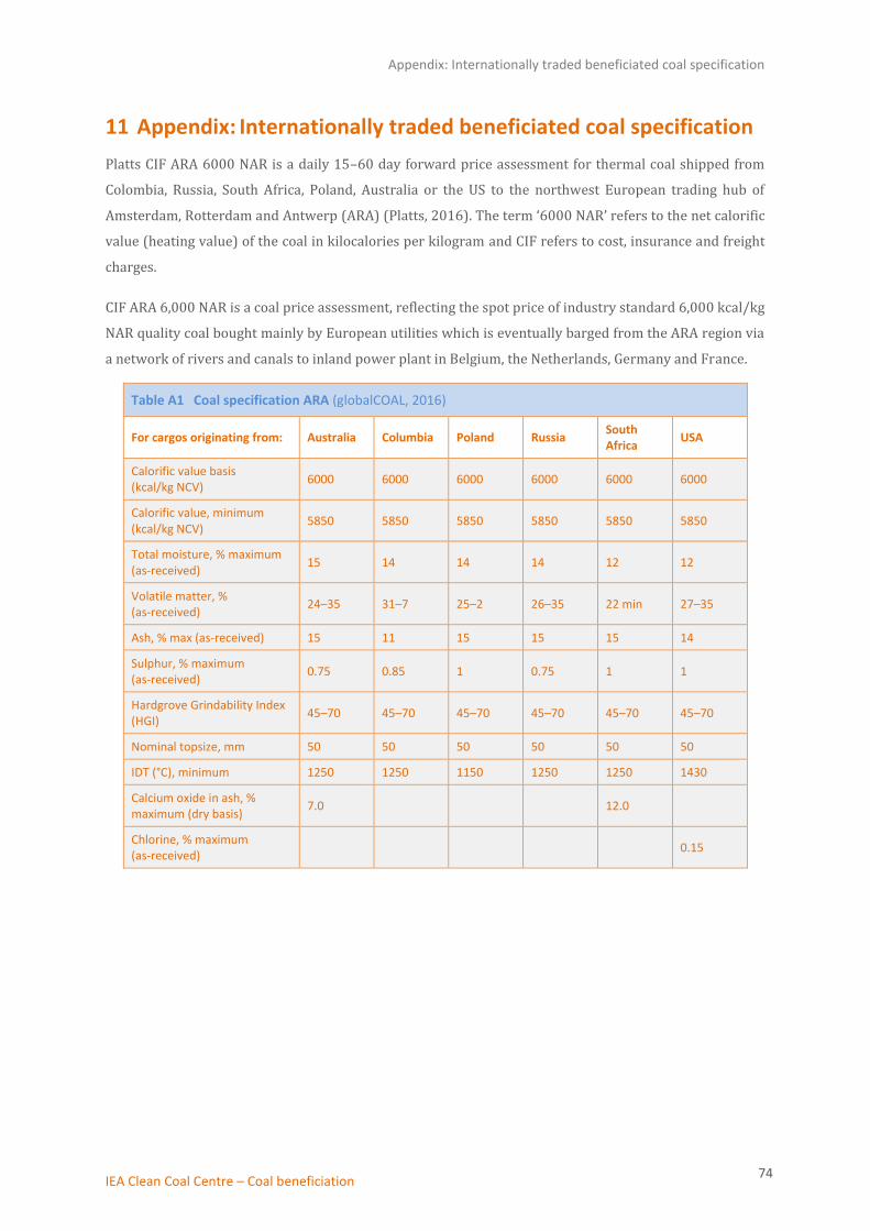
Appendix: Internationally traded beneficiated coal specification
IEA Clean Coal Centre – Coal beneficiation 74
11 Appendix: Internationally traded beneficiated coal specification
Platts CIF ARA 6000 NAR is a daily 15–60 day forward price assessment for thermal coal shipped from
Colombia, Russia, South Africa, Poland, Australia or the US to the northwest European trading hub of
Amsterdam, Rotterdam and Antwerp (ARA) (Platts, 2016). The term ‘6000 NAR’ refers to the net calorific
value (heating value) of the coal in kilocalories per kilogram and CIF refers to cost, insurance and freight
charges.
CIF ARA 6,000 NAR is a coal price assessment, reflecting the spot price of industry standard 6,000 kcal/kg
NAR quality coal bought mainly by European utilities which is eventually barged from the ARA region via
a network of rivers and canals to inland power plant in Belgium, the Netherlands, Germany and France.
Table A1 Coal specification ARA (globalCOAL, 2016)
For cargos originating from: Australia Columbia Poland Russia South Africa
USA
Calorific value basis (kcal/kg NCV)
6000 6000 6000 6000 6000 6000
Calorific value, minimum (kcal/kg NCV)
5850 5850 5850 5850 5850 5850
Total moisture, % maximum (as-received)
15 14 14 14 12 12
Volatile matter, % (as-received)
24–35 31–7 25–2 26–35 22 min 27–35
Ash, % max (as-received) 15 11 15 15 15 14
Sulphur, % maximum (as-received)
0.75 0.85 1 0.75 1 1
Hardgrove Grindability Index (HGI)
45–70 45–70 45–70 45–70 45–70 45–70
Nominal topsize, mm 50 50 50 50 50 50
IDT (°C), minimum 1250 1250 1150 1250 1250 1430
Calcium oxide in ash, % maximum (dry basis)
7.0 12.0
Chlorine, % maximum (as-received)
0.15


![Reid and the Department of Defence [2017] DHAAT 22 (30 ...€¦ · Reid and the Department of Defence [2017] DHAAT 22 (30 November 2017) File Number 2017/02 . Re Mr Ian Reid. Applicant](https://img.pdfslide.net/doc/110x75/5eae626a3e573254697c79ed/reid-and-the-department-of-defence-2017-dhaat-22-30-reid-and-the-department.jpg)

![Solving Inverse Problems arXiv:1603.05015v1 [cs.CV] 16 Mar ... · Non-linear Dimensionality Regularizer for Solving Inverse Problems Ravi Garg, Anders Eriksson, and Ian Reid 1 University](https://img.pdfslide.net/doc/110x75/601f102c0e58e857415fff9d/solving-inverse-problems-arxiv160305015v1-cscv-16-mar-non-linear-dimensionality.jpg)