Embed Size (px)
Citation preview

B.E. 4/4 ECE 422 RADAR ENGINEERING AND NAVIGATIONAL AIDS
Dr. K.Murali KrishnaB.Tech., M.E., Ph.D, MISTE, MIEEE, Fellow IETE
Professor
Department of Electronics and Communication Engineering,
ANITS
1. Mixera. Noise figure
b. Receiver Noise Figure
2. Ideal Mixer
3. Types of Mixersa. Single-ended Mixer
b. Balanced Mixer
c. Double- balanced Mixer,
d. Image-rejection Mixer
e. Image-recovery Mixer
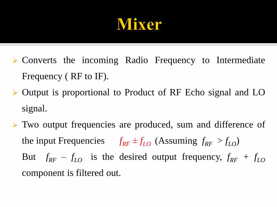
Converts the incoming Radio Frequency to Intermediate
Frequency ( RF to IF).
Output is proportional to Product of RF Echo signal and LO
signal.
Two output frequencies are produced, sum and difference of
the input Frequencies fRF ± fLO (Assuming fRF > fLO)
But fRF – fLO is the desired output frequency, fRF + fLO
component is filtered out.

There are two possible difference frequency signals :
fRF – fLO and fLO - fRF (When fRF< fLO).
only one of these two is desired frequency, the other is
called image frequency.
This image frequency is to be rejected using RF filter
or a special type of mixer called Image-reject mixer.

Noise figure is dependent on conversion loss and noise-temperature ratio.
1. Conversion Loss
2. Noise-Temperature ratio
1. Conversion Loss Lc
Available RF Power / Available IF Power
2. Noise-Temperature ratio tr
Actual available IF noise power / Available noise power from an equivalent resistance

Noise Temperature Ratio
tr = Fm Gc = Fm Lc
Fm is the noise figure due to mixer
Where Lc = Conversion Loss = 1/ Gc
Tr varies inversely with IF frequency
Lower the conversion rate larger is the tr .
Receiver Noise Figure includes the IF amplifier noise figure too which becomes more dominant.
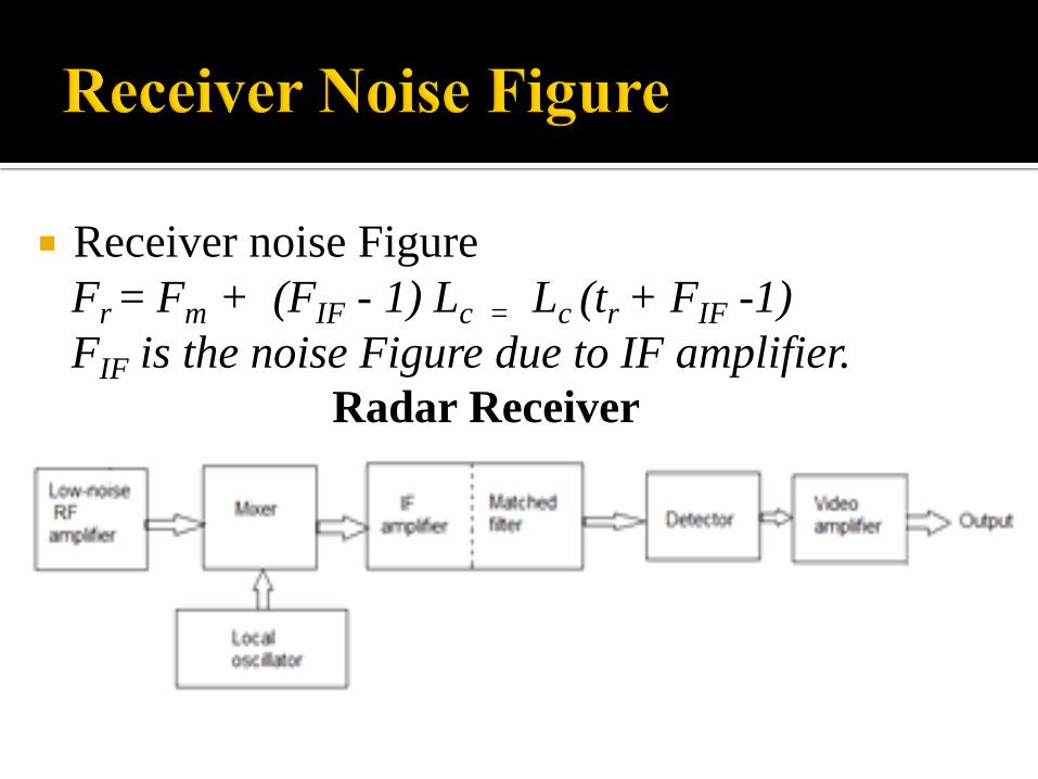
Receiver noise Figure
Fr = Fm + (FIF - 1) Lc = Lc (tr + FIF -1)
FIF is the noise Figure due to IF amplifier.
Radar Receiver

An ideal mixer must possess the following characters
1. Low conversion loss
2. Minimized spurious responses
3. Should not be susceptible to burnout
4. Large noise-temperature ratio.
1. Single-ended Mixer
2. Balanced Mixer
3. Double- balanced Mixer
4. Image-rejection Mixer
5. Image-recovery Mixer

Also called as an unbalanced or crystal mixer.
Uses a single diode that terminates a transmission
line, LO is inserted via a directional coupler.
An LPF after the diode filters out RF and LO signals
allowing only IF.
The unwanted Image frequency is short circuited or
Open circuited.

Diode being a non-linear device produces inter-
modulation products, called Spurious responses.
(When mfRF + nfLO = fIF )
Taylor proposed a mixer chart to determine the
RF and LO frequencies that are free from
spurious responses.
A Mixer chart is a graphical representation of
wanted and unwanted (spurious) mixing products
in-band and out-of-band.

Presence of two or more RF signals also
results in spurious responses.
LO noise is to be removed by an RF filter
between LO and Mixer.
Single conversion receivers suppress these
spurious responses.

LPFIF outRF input
LO
input
Directional Coupler
Diode
In some cases the RF and LO signals are subjected to a
Diplexer in order to provide proper isolation between
them.

Two single ended mixer in parallel and 180o
out of phase.
A 4-port junction such as magic-T, hybrid
junction or 3dB coupler is used.
LO and RF signals are applied at ports 1 and
2, their sum and difference is obtained at ports
3 and 4.
Diode mixers are present at ports output of
ports 3 & 4.


IF signal = Difference of the outputs of the two
diode mixers.
Perks:
LO noise at the two diode mixers are in phase
and gets cancelled out
Suppresses the even harmonics of either LO
signal or the RF signals.

• Uses four switching devices (diodes) arranged in
form of a ring network
• Wire wound transformer is used as BALUN

Advantages: Better isolation between RF and LO ports.
Permits wide bandwidth.
Suppresses even harmonics of both LO and RF ports.
Drawbacks:
High LO drive required.
Increased cost and complexity.

The RF signal is split into two and fed into two
individual mixers.
LO signal is split into two using a 90o Hybrid junction.
A second hybrid junction (IF) imparts another 90o phase
shift to separate the image frequency.
The port with the image frequency is match terminated.

RF inLO in
90o
Hybrid junction
(RF)
90o
Hybrid junction
(IF)
90o
Hybrid junction
RF
RF
IF Out
Terminated
Image
frequency
IF
IF

Advantages
High Dynamic range
Good VSWR.
Low Inter-modulation Products.
Less susceptibility to Burn out.
Drawback:
Provides only 30dB image rejection, which may
not be suitable for some applications.
High noise figure.

Dynamic Range of a radar receiver is the Ratio of
max input signal power to minimum input signal
power without degradation in performance.
Third order modulation product affects the dynamic
range of radar.
Third-order distortion products are produced by a
nonlinear device when two tones closely spaced in
frequency are fed into its input

It is a modified version of Image-rejection mixer.
Mixer conversion loss is reduced by terminating a
diode in a reactance at the image frequency.
The improvement using this image enhancement is
as low as 1 or 2 dB.
Band pass filtering around the input source
prevents the image frequency from entering into
the mixer again.


The ideal radar receiver is required to: amplify the received signals without adding
noise or introducing any form of distortion;optimise the probability of detection of the
signal by its bandwidth characteristics;provide a large dynamic range to
accommodate large clutter signals; reject interfering signals so that the required
information can be optimally detected.
The minimum receivable power (Pemin) for a given receiver is important because
the minimum receivable power is one of the factors which determine the
maximum range performance of the radar.
The sensitivity level MDS has got a value of 10 -13 Watts ( -100 dBm) for a typical
radar receiver.
All receivers are designed for a certain sensitivity level based on requirements.
One would not design a receiver with more sensitivity than required because it
limits the receiver bandwidth and will require the receiver to process signals it is
not interested in.
In general, while processing signals, the higher the power level at which the
sensitivity is set, the fewer the number of false alarms which will be processed.
Simultaneously, the probability of detection of a “good” (low-noise) signal will be
decreased.
Minimum Detectable Signal (MDS)

One of the most important factor is receiver noise.
Every receiver adds a certain amount of noise to its input signal, and a radar receiver is
no exception.
Even with very careful design, noise due to thermal motion of electrons in resistive
components is unavoidable.
The amount of such thermal noise is proportional to receiver bandwidth.
Therefore, bandwidth reduction is a possible solution to the problem of receiver noise.
However, if the bandwidth is made too small the receiver does not amplify
and process signal echoes properly.
A compromise is required. In practice, the receiver bandwidth of a pulse radar is
normally close to the reciprocal of the pulse duration. For example, a radar using 1 µs
pulses may be expected to have a bandwidth of about 1 Mhz.

The receiver system must amplify the received signal without distortion.
If a large clutter signal sends the system into saturation, the result is a
modification to the spectrum of the signal.
This change in spectral content reduces the ability of the signal processor
to carry out Doppler processing and degrades the MTI improvement
factor. Furthermore, if the receiver enters saturation, then there can be a
delay before target detection is restored.
In principle, the dynamic range of the receiver must exceed the total range
of signal strength from noise level up to the largest clutter signal.
In practice dynamic ranges of 80 dB’s or so meets system requirements.The clutter power confirms this requirement as it averages:
▪ Rain clutter up to 55 dB▪ Angels to 70 dB▪ Sea clutter to 75 dB▪ Ground clutter to 90 dB.
INTRODUCTION TO RADAR SYSTEMS, 3rd Edition, Meril.L.Skolnik.
Practical RF Circuit Design for Modern Wireless Systems, Volume 2 By Rowan Gilmore, Les Besser.
http://www.microwaves101.com/
http://www.radartutorial.eu/
Mixer Basics Primer A Tutorial for RF & Microwave Mixers by: Ferenc Marki & Christopher Marki, Ph.D