Embed Size (px)
Citation preview
Dr. Tahseen Al-DooriDr. Tahseen Al-Doori
Lesson 2Lesson 2
Radio Frequency FundamentalsRadio Frequency Fundamentals
Dr. Tahseen Al-DooriDr. Tahseen Al-Doori
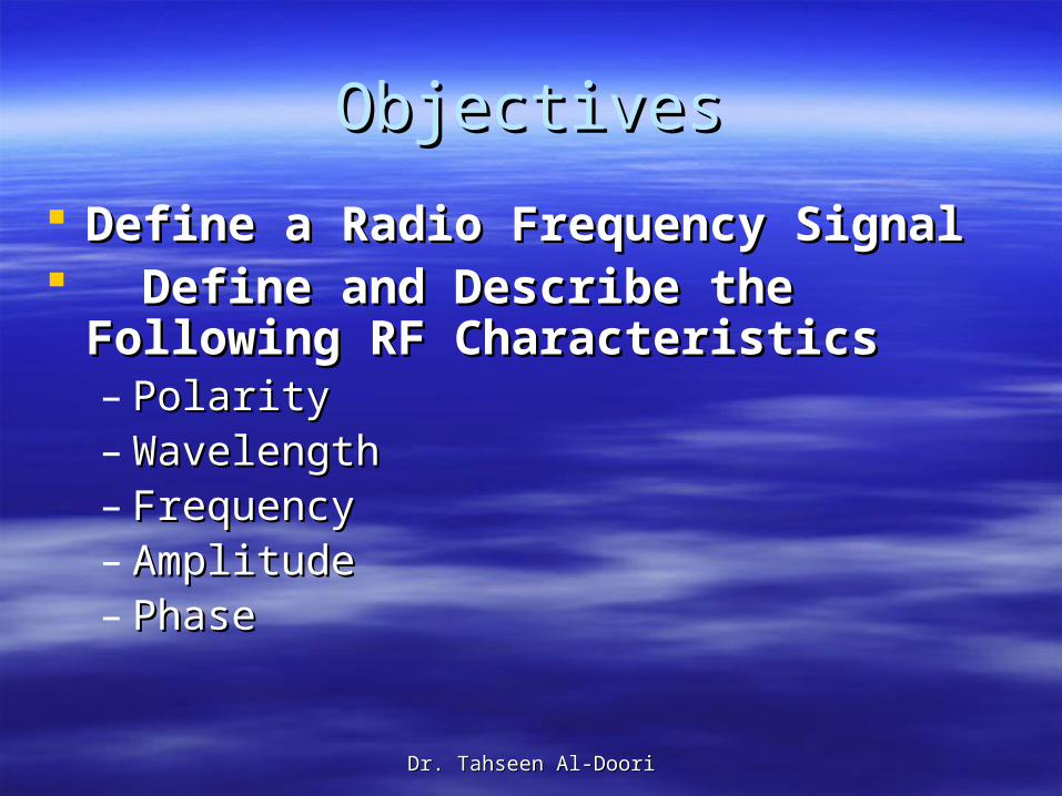
ObjectivesObjectives
Define a Radio Frequency SignalDefine a Radio Frequency Signal Define and Describe the Following RF Define and Describe the Following RF
CharacteristicsCharacteristics – PolarityPolarity– WavelengthWavelength– FrequencyFrequency– AmplitudeAmplitude– PhasePhase
Dr. Tahseen Al-DooriDr. Tahseen Al-Doori
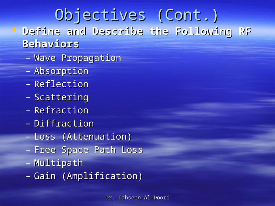
Objectives (Cont.)Objectives (Cont.) Define and Describe the Following RF Define and Describe the Following RF
BehaviorsBehaviors – Wave PropagationWave Propagation– AbsorptionAbsorption– ReflectionReflection– ScatteringScattering– RefractionRefraction– DiffractionDiffraction– Loss (Attenuation)Loss (Attenuation)– Free Space Path LossFree Space Path Loss– MultipathMultipath– Gain (Amplification)Gain (Amplification)
Dr. Tahseen Al-DooriDr. Tahseen Al-Doori
To properly design, deploy, and administer an To properly design, deploy, and administer an 802.11 wireless network, in addition to 802.11 wireless network, in addition to understanding the OSI model and basic understanding the OSI model and basic networking concepts, you must broaden your networking concepts, you must broaden your understanding of many other networking understanding of many other networking technologies. technologies.
For instance, when administering an Ethernet For instance, when administering an Ethernet network, you typically need a comprehension of network, you typically need a comprehension of TCP/IP, bridging, switching, and routing. The skills TCP/IP, bridging, switching, and routing. The skills to manage an Ethernet network will also aid you to manage an Ethernet network will also aid you as a Wi-Fi administer because most 802.11 as a Wi-Fi administer because most 802.11 wireless networks act as “portals” into wired wireless networks act as “portals” into wired networks. The IEEE only defines the 802.11 networks. The IEEE only defines the 802.11 technologies at the Physical layer and the MAC technologies at the Physical layer and the MAC sublayer of the Data-Link layer.sublayer of the Data-Link layer.
Dr. Tahseen Al-DooriDr. Tahseen Al-Doori
In order to fully understand the 802.11 In order to fully understand the 802.11 technology, it is necessary to have a clear technology, it is necessary to have a clear concept of how wireless works at the first concept of how wireless works at the first layer of the OSI model, and at the heart of layer of the OSI model, and at the heart of the Physical layer is radio frequency (RF) the Physical layer is radio frequency (RF) communications.communications.
Dr. Tahseen Al-DooriDr. Tahseen Al-Doori
if you have a good grasp of the RF characteristics if you have a good grasp of the RF characteristics and behaviors, your skills as a wireless network and behaviors, your skills as a wireless network administrator will be ahead of the curve. administrator will be ahead of the curve.
Why does a wireless network perform differently in Why does a wireless network perform differently in an auditorium full of people than it does inside an an auditorium full of people than it does inside an empty auditorium? Why does the performance of a empty auditorium? Why does the performance of a wireless LAN seem to degrade in a storage area wireless LAN seem to degrade in a storage area with metal racks? Why does the range of a 5 GHz with metal racks? Why does the range of a 5 GHz radio transmitter seem shorter than the range of a radio transmitter seem shorter than the range of a 2.4 GHz radio card? These are the type of 2.4 GHz radio card? These are the type of questions that can be answered with some basic questions that can be answered with some basic knowledge of how RF signals work and perform. knowledge of how RF signals work and perform.
Dr. Tahseen Al-DooriDr. Tahseen Al-Doori
What Is an RF (Radio Frequency) What Is an RF (Radio Frequency) Signal?Signal?
An RF signal radiates in a continuous pattern that is An RF signal radiates in a continuous pattern that is governed by certain properties such as wavelength, governed by certain properties such as wavelength, frequency, amplitude, phase, and polarity. Additionally, frequency, amplitude, phase, and polarity. Additionally, electromagnetic signals can travel through mediums of electromagnetic signals can travel through mediums of different materials or travel in a perfect vacuum. different materials or travel in a perfect vacuum.
When an RF signal travels through a vacuum, it moves at When an RF signal travels through a vacuum, it moves at the speed of light, which is approximately 300,000,000 the speed of light, which is approximately 300,000,000 meters per second, or 186,000 miles per second. meters per second, or 186,000 miles per second.
RF signals travel using a variety or combination of RF signals travel using a variety or combination of movement behaviors. These movement behaviors are movement behaviors. These movement behaviors are referred to as referred to as propagationpropagation behaviors. We will discuss some behaviors. We will discuss some of these propagation behaviors later, including absorption, of these propagation behaviors later, including absorption, reflection, scattering, refraction, diffraction, amplification, reflection, scattering, refraction, diffraction, amplification, and attenuation.and attenuation.
Dr. Tahseen Al-DooriDr. Tahseen Al-Doori
Identifying Radio Frequency Identifying Radio Frequency Characteristics Characteristics
In every RF signal exists characteristic that are In every RF signal exists characteristic that are defined by the laws of physics:defined by the laws of physics:
PolarityPolarity WavelengthWavelength FrequencyFrequency AmplitudeAmplitude PhasePhaseWe will look at each of these in more detail in the We will look at each of these in more detail in the
following sections. following sections.
Dr. Tahseen Al-DooriDr. Tahseen Al-Doori
PolarityPolarity
When the movement of the electron flow When the movement of the electron flow changes direction in an antenna, changes direction in an antenna, electromagnetic waves that change and electromagnetic waves that change and move away from the antenna are also move away from the antenna are also produced. produced.
The waves consist of two component fields: The waves consist of two component fields: the electrical (E-field) and the H-field, which the electrical (E-field) and the H-field, which is magnetic.is magnetic.
Dr. Tahseen Al-DooriDr. Tahseen Al-Doori
Think of a wave as a physical disturbance that Think of a wave as a physical disturbance that transfers energy back and forth between these two transfers energy back and forth between these two fields. These fields are at right angles to each fields. These fields are at right angles to each other, and the transfer of energy between these other, and the transfer of energy between these fields is known as fields is known as oscillationoscillation. .
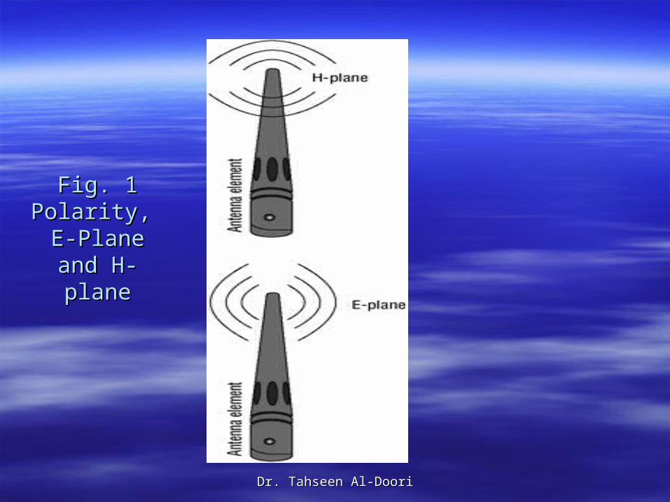
Polarization is the vertical or horizontal positioning Polarization is the vertical or horizontal positioning of an antenna. The orientation of the antenna of an antenna. The orientation of the antenna affects the affects the polaritypolarity of the signal. The electric field of the signal. The electric field always resides parallel in the same orientation always resides parallel in the same orientation (plane) of the antenna element. As shown in (plane) of the antenna element. As shown in Figure 1Figure 1, the parallel plane is called the E-plane , the parallel plane is called the E-plane and the plane that is perpendicular to the antenna and the plane that is perpendicular to the antenna element is known as the H-plane. element is known as the H-plane.
Dr. Tahseen Al-DooriDr. Tahseen Al-Doori
Fig. 1Fig. 1Polarity, Polarity,
E-Plane and E-Plane and H-planeH-plane
Dr. Tahseen Al-DooriDr. Tahseen Al-Doori
WavelengthWavelength
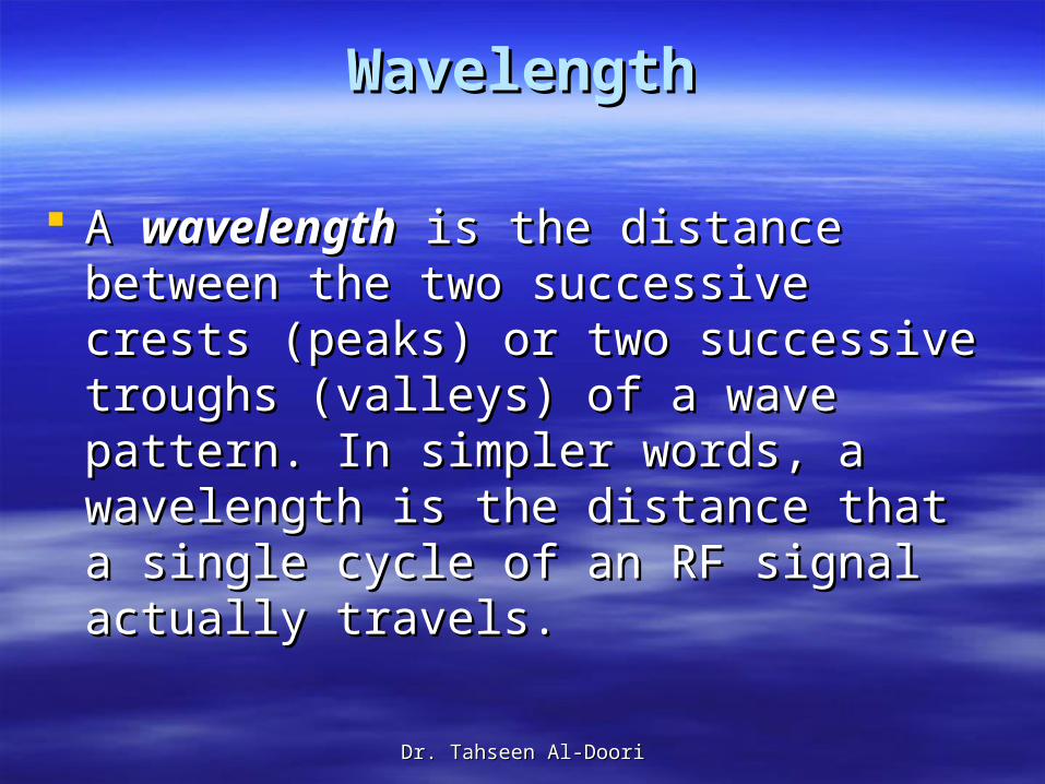
A A wavelengthwavelength is the distance between the is the distance between the two successive crests (peaks) or two two successive crests (peaks) or two successive troughs (valleys) of a wave successive troughs (valleys) of a wave pattern. In simpler words, a wavelength is pattern. In simpler words, a wavelength is the distance that a single cycle of an RF the distance that a single cycle of an RF signal actually travels.signal actually travels.
Dr. Tahseen Al-DooriDr. Tahseen Al-Doori
It is very important to understand the following It is very important to understand the following statement: statement:
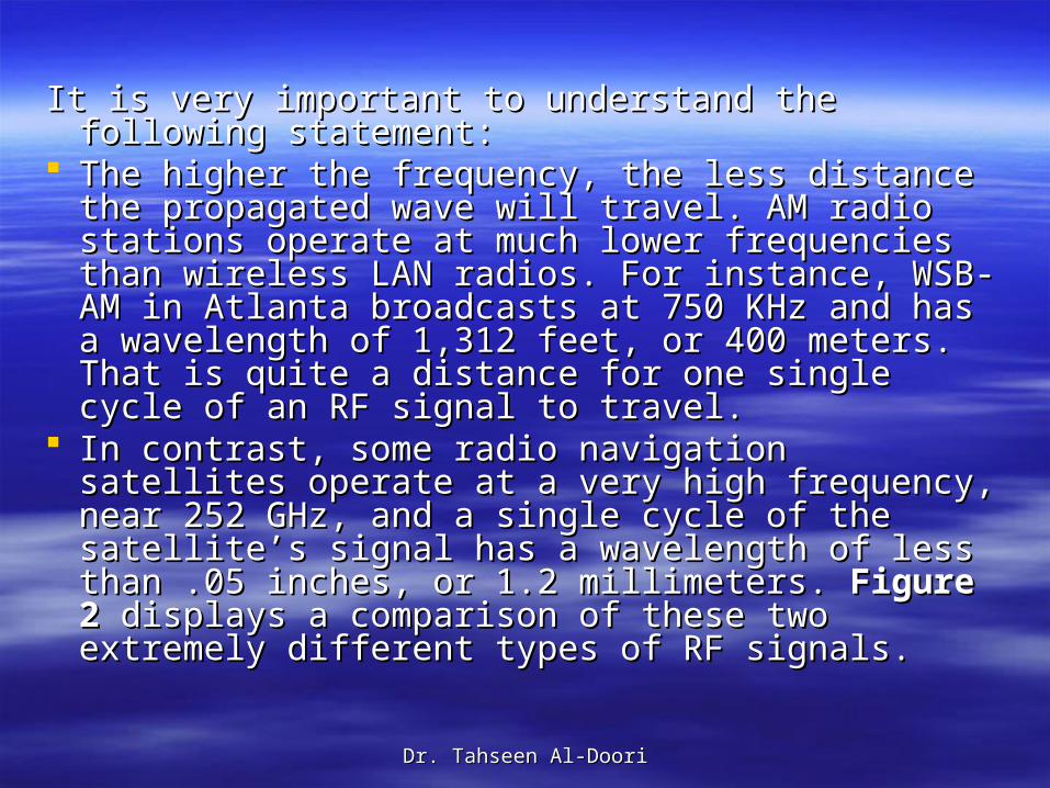
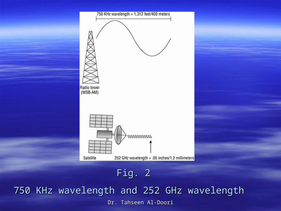
The higher the frequency, the less distance the The higher the frequency, the less distance the propagated wave will travel. AM radio stations propagated wave will travel. AM radio stations operate at much lower frequencies than wireless operate at much lower frequencies than wireless LAN radios. For instance, WSB-AM in Atlanta LAN radios. For instance, WSB-AM in Atlanta broadcasts at 750 KHz and has a wavelength of broadcasts at 750 KHz and has a wavelength of 1,312 feet, or 400 meters. That is quite a distance 1,312 feet, or 400 meters. That is quite a distance for one single cycle of an RF signal to travel. for one single cycle of an RF signal to travel.
In contrast, some radio navigation satellites In contrast, some radio navigation satellites operate at a very high frequency, near 252 GHz, operate at a very high frequency, near 252 GHz, and a single cycle of the satellite’s signal has a and a single cycle of the satellite’s signal has a wavelength of less than .05 inches, or 1.2 wavelength of less than .05 inches, or 1.2 millimeters. millimeters. Figure 2Figure 2 displays a comparison of displays a comparison of these two extremely different types of RF signals.these two extremely different types of RF signals.
Dr. Tahseen Al-DooriDr. Tahseen Al-Doori
Fig. 2Fig. 2
750 KHz wavelength and 252 GHz wavelength750 KHz wavelength and 252 GHz wavelength
Dr. Tahseen Al-DooriDr. Tahseen Al-Doori
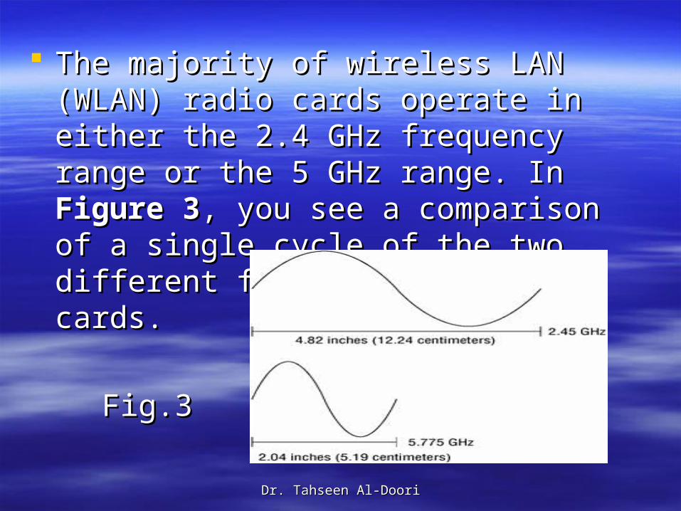
The majority of wireless LAN (WLAN) radio The majority of wireless LAN (WLAN) radio cards operate in either the 2.4 GHz cards operate in either the 2.4 GHz frequency range or the 5 GHz range. In frequency range or the 5 GHz range. In Figure 3Figure 3, you see a comparison of a single , you see a comparison of a single cycle of the two different frequency WLAN cycle of the two different frequency WLAN radio cards.radio cards.
Fig.3Fig.3
Dr. Tahseen Al-DooriDr. Tahseen Al-Doori
As you can see by these illustrations, the As you can see by these illustrations, the wavelengths of the different frequency wavelengths of the different frequency signals are different because, although each signals are different because, although each signal only cycles one time, the waves travel signal only cycles one time, the waves travel dissimilar distances.dissimilar distances.
Wavelength=C/Freq.Wavelength=C/Freq. Where C=3x10^8Where C=3x10^8 Because the wavelength property is shorter Because the wavelength property is shorter
in the 5 GHz frequency range, Wi-Fi in the 5 GHz frequency range, Wi-Fi equipment using 5 GHz radio cards will equipment using 5 GHz radio cards will have shorter range and coverage area than have shorter range and coverage area than Wi-Fi equipment using 2.4 GHz radio cards.Wi-Fi equipment using 2.4 GHz radio cards.
Dr. Tahseen Al-DooriDr. Tahseen Al-Doori
FrequencyFrequency
Frequency is the number of times a Frequency is the number of times a specified event occurs within a specified specified event occurs within a specified time interval. time interval.
The measurement unit for frequency is Hz.The measurement unit for frequency is Hz.
Dr. Tahseen Al-DooriDr. Tahseen Al-Doori
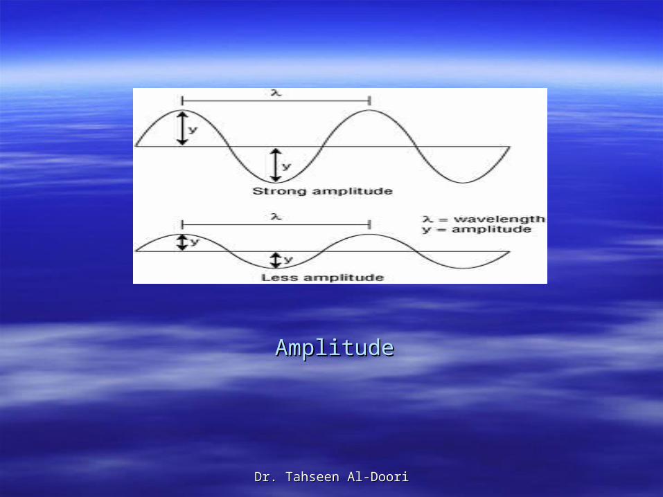
AmplitudeAmplitude In In Fig. 4Fig. 4, you can see that (λ) represents , you can see that (λ) represents
wavelength and (y) represents the wavelength and (y) represents the amplitude. amplitude.
The first signal’s crests and troughs have The first signal’s crests and troughs have more magnitude, thus it has more more magnitude, thus it has more amplitude. amplitude.
The second signal’s crests and troughs The second signal’s crests and troughs have decreased, and therefore the signal have decreased, and therefore the signal has less amplitude.has less amplitude.
Dr. Tahseen Al-DooriDr. Tahseen Al-Doori
AmplitudeAmplitude
Dr. Tahseen Al-DooriDr. Tahseen Al-Doori
Note that although the signal strength Note that although the signal strength (amplitude) is different, the frequency of the (amplitude) is different, the frequency of the signal remains constant. signal remains constant.
A variety of factors can cause an RF signal A variety of factors can cause an RF signal to lose amplitude, otherwise known as to lose amplitude, otherwise known as attenuation, which we will discuss later in attenuation, which we will discuss later in this chapter in the section “this chapter in the section “Loss Loss (Attenuation)(Attenuation).”.”
Dr. Tahseen Al-DooriDr. Tahseen Al-Doori
PhasePhase Phase is not a property of just one RF signal but Phase is not a property of just one RF signal but
instead involves the relationship between two or instead involves the relationship between two or more signals that share the same frequency. The more signals that share the same frequency. The phase involves the relationship between the phase involves the relationship between the position of the amplitude crests and troughs of two position of the amplitude crests and troughs of two waveforms. waveforms.
Phase can be measured in distance, time, or Phase can be measured in distance, time, or degrees. If the peaks of two signals with the same degrees. If the peaks of two signals with the same frequency are in exact alignment at the same time, frequency are in exact alignment at the same time, they are said to be they are said to be in phasein phase. .
Dr. Tahseen Al-DooriDr. Tahseen Al-Doori
What is important to understand is the effect that What is important to understand is the effect that phase has on amplitude when radio cards receive phase has on amplitude when radio cards receive multiple signals. multiple signals.
Signals that have 0 (zero) degrees phase Signals that have 0 (zero) degrees phase separation (in phase) actually combine their separation (in phase) actually combine their amplitude, which results in a received signal of amplitude, which results in a received signal of much greater signal strength, or twice the much greater signal strength, or twice the amplitude. amplitude.
If two RF signals are 180 degrees out of phase If two RF signals are 180 degrees out of phase (the peak of one signal is in exact alignment with (the peak of one signal is in exact alignment with the trough of the second signal), they cancel each the trough of the second signal), they cancel each other out and the effective received signal strength other out and the effective received signal strength is null. is null.
Depending on the amount of phase separation of Depending on the amount of phase separation of two signals, the received signal strength may be two signals, the received signal strength may be either cumulative or diminished. either cumulative or diminished.
Dr. Tahseen Al-DooriDr. Tahseen Al-Doori
Identifying RF Behaviors Identifying RF Behaviors
As an RF signal travels through the air and As an RF signal travels through the air and other different mediums, it can move and other different mediums, it can move and behave in different manners. behave in different manners.
RF propagation behaviors include RF propagation behaviors include absorption, reflection, scattering, refraction, absorption, reflection, scattering, refraction, diffraction, loss, free space path loss, multi-diffraction, loss, free space path loss, multi-path, attenuation, and gain.path, attenuation, and gain.
Dr. Tahseen Al-DooriDr. Tahseen Al-Doori
Wave Propagation Wave Propagation
Now that you have learned about some of the Now that you have learned about some of the various characteristics of an RF signal, it is various characteristics of an RF signal, it is important to have an understanding of the way an important to have an understanding of the way an RF signal behaves as it moves away from an RF signal behaves as it moves away from an antenna. antenna.
The way in which the RF waves move—known as The way in which the RF waves move—known as wave propagationwave propagation—can vary drastically —can vary drastically depending on the materials in the signal’s path. depending on the materials in the signal’s path. Drywall will have a much different effect on an RF Drywall will have a much different effect on an RF signal than metal. signal than metal.
Dr. Tahseen Al-DooriDr. Tahseen Al-Doori
What happens to an RF signal between two What happens to an RF signal between two locations is a direct result of how the signal locations is a direct result of how the signal propagates. propagates.
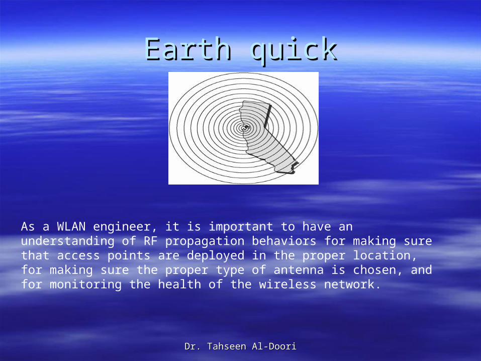
When we use the term When we use the term propagatepropagate, try to envision , try to envision an RF signal broadening or spreading as it travels an RF signal broadening or spreading as it travels farther away from the antenna. An excellent farther away from the antenna. An excellent analogy is shown in analogy is shown in Figure 5Figure 5, which depicts an , which depicts an earthquake. Note the concentric seismic rings that earthquake. Note the concentric seismic rings that propagate away from the epicenter of the propagate away from the epicenter of the earthquake. earthquake.
RF waves behave in much the same fashion. The RF waves behave in much the same fashion. The manner in which a wireless signal moves is often manner in which a wireless signal moves is often referred to as propagation behavior. referred to as propagation behavior.
Dr. Tahseen Al-DooriDr. Tahseen Al-Doori
Earth quickEarth quick
As a WLAN engineer, it is important to have an understanding of RF propagation behaviors for making sure that access points are deployed in the proper location, for making sure the proper type of antenna is chosen, and for monitoring the health of the wireless network.
Dr. Tahseen Al-DooriDr. Tahseen Al-Doori
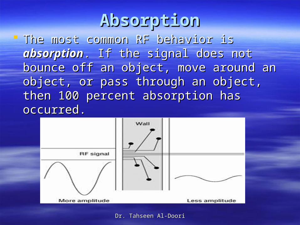
AbsorptionAbsorption The most common RF behavior is The most common RF behavior is
absorptionabsorption. If the signal does not bounce . If the signal does not bounce off an object, move around an object, or off an object, move around an object, or pass through an object, then 100 percent pass through an object, then 100 percent absorption has occurred. absorption has occurred.
Dr. Tahseen Al-DooriDr. Tahseen Al-Doori
ScenarioScenario
Mr. Sabir performs a wireless site survey at a Mr. Sabir performs a wireless site survey at a campus lecture hall. He determined how many campus lecture hall. He determined how many access points are required and their proper access points are required and their proper placement so that he will have the necessary RF placement so that he will have the necessary RF coverage. Ten days later, Professor Banks gives a coverage. Ten days later, Professor Banks gives a heavily attended lecture on business economics. heavily attended lecture on business economics. During this lecture, the signal strength and quality During this lecture, the signal strength and quality of the wireless LAN was less than desirable. What of the wireless LAN was less than desirable. What happened? happened?
Dr. Tahseen Al-DooriDr. Tahseen Al-Doori
ReflectionReflection
One of the most important RF propagation One of the most important RF propagation behaviors to be aware of is reflection. When behaviors to be aware of is reflection. When a wave hits a smooth object that is larger a wave hits a smooth object that is larger than the wave itself, depending upon the than the wave itself, depending upon the media, the wave may bounce in another media, the wave may bounce in another direction. direction.
This behavior is categorized as This behavior is categorized as reflectionreflection. .
Dr. Tahseen Al-DooriDr. Tahseen Al-Doori
There are two major types of reflections: There are two major types of reflections: sky wave reflection and microwave sky wave reflection and microwave
reflection. reflection. Sky wave reflection can occur in Sky wave reflection can occur in
frequencies below 1 GHz where the signal frequencies below 1 GHz where the signal has a very large wavelength. The signal has a very large wavelength. The signal bounces off the surface of the charged bounces off the surface of the charged particles of the ionosphere in the earth’s particles of the ionosphere in the earth’s atmosphere. This is why you can be in atmosphere. This is why you can be in Dubai, UAE, and listen to Iran Station on a Dubai, UAE, and listen to Iran Station on a clear night.clear night.
Dr. Tahseen Al-DooriDr. Tahseen Al-Doori
Microwave signals, however, exist between 1 GHz Microwave signals, however, exist between 1 GHz and 300 GHz. Because they are higher-frequency and 300 GHz. Because they are higher-frequency signals, they have much smaller wavelengths, signals, they have much smaller wavelengths, thus the term thus the term microwavemicrowave. .
Microwaves can bounce off of smaller objects like Microwaves can bounce off of smaller objects like a metal door. a metal door.
Microwave reflection is what we are concerned Microwave reflection is what we are concerned about in wireless LAN environments. In an outdoor about in wireless LAN environments. In an outdoor environment, microwaves can reflect off of large environment, microwaves can reflect off of large objects and smooth surfaces such as buildings, objects and smooth surfaces such as buildings, roads, bodies of water, and even the earth’s roads, bodies of water, and even the earth’s surface. In an indoor environment, microwaves surface. In an indoor environment, microwaves reflect off of smooth surfaces such as doors, walls, reflect off of smooth surfaces such as doors, walls, and file cabinets. Anything made of metal will and file cabinets. Anything made of metal will absolutely cause reflection. Other materials such absolutely cause reflection. Other materials such as glass and concrete may cause reflection as as glass and concrete may cause reflection as well. well.
Dr. Tahseen Al-DooriDr. Tahseen Al-Doori
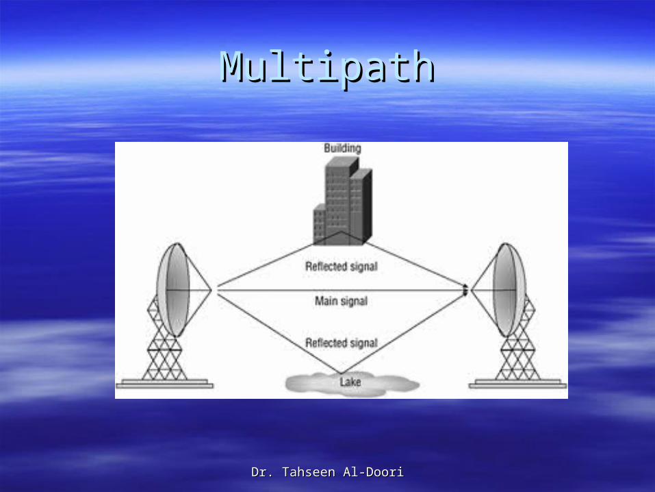
Reflection can be the cause of serious Reflection can be the cause of serious performance problems in a wireless LAN. performance problems in a wireless LAN.
As a wave radiates from an antenna, it As a wave radiates from an antenna, it broadens and disperses. If portions of this broadens and disperses. If portions of this wave are reflected, new wave fronts will wave are reflected, new wave fronts will appear from the reflection points. If these appear from the reflection points. If these multiple waves all reach the receiver, the multiple waves all reach the receiver, the multiple reflected signals cause an effect multiple reflected signals cause an effect called multipath.called multipath.
Multipath can degrade the strength and Multipath can degrade the strength and quality of the received signal or even cause quality of the received signal or even cause data corruption or cancelled signals. data corruption or cancelled signals.
Dr. Tahseen Al-DooriDr. Tahseen Al-Doori
Although reflection and multipath can be Although reflection and multipath can be your number one enemy, new antenna your number one enemy, new antenna technologies such as Multiple Input Multiple technologies such as Multiple Input Multiple Output (MIMO) may become commonplace Output (MIMO) may become commonplace in the future to actually take advantage of in the future to actually take advantage of reflected signals.reflected signals.
MIMO is very much WiMax technology.MIMO is very much WiMax technology.
Dr. Tahseen Al-DooriDr. Tahseen Al-Doori
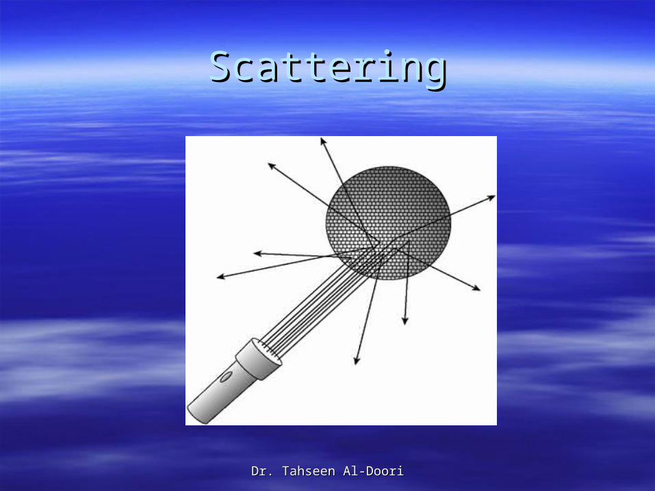
ScatteringScattering
Did you know that the color of the sky is blue Did you know that the color of the sky is blue because the wavelength of light is smaller than the because the wavelength of light is smaller than the molecules of the atmosphere? This blue sky molecules of the atmosphere? This blue sky phenomenon is known as Rayleigh scattering. phenomenon is known as Rayleigh scattering.
The shorter blue wavelength light is absorbed by The shorter blue wavelength light is absorbed by the gases in the atmosphere and radiated in all the gases in the atmosphere and radiated in all directions. directions.
This is another example of an RF propagation This is another example of an RF propagation behavior called behavior called scatteringscattering, sometimes called , sometimes called scatter.scatter.
Dr. Tahseen Al-DooriDr. Tahseen Al-Doori
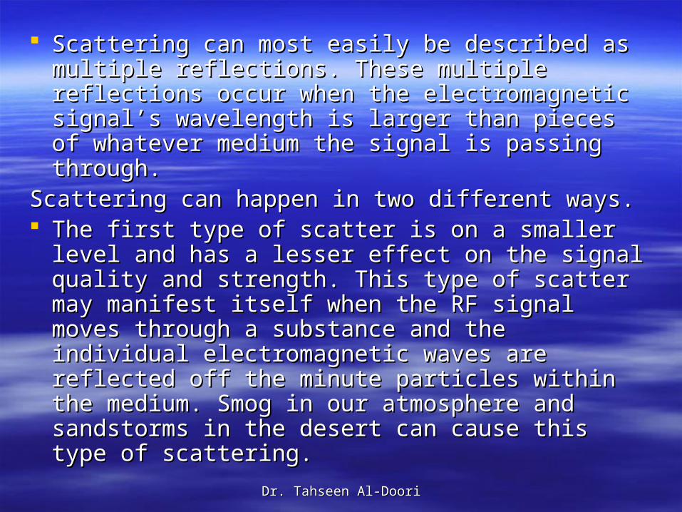
Scattering can most easily be described as Scattering can most easily be described as multiple reflections. These multiple reflections multiple reflections. These multiple reflections occur when the electromagnetic signal’s occur when the electromagnetic signal’s wavelength is larger than pieces of whatever wavelength is larger than pieces of whatever medium the signal is passing through.medium the signal is passing through.
Scattering can happen in two different ways. Scattering can happen in two different ways. The first type of scatter is on a smaller level and The first type of scatter is on a smaller level and
has a lesser effect on the signal quality and has a lesser effect on the signal quality and strength. This type of scatter may manifest itself strength. This type of scatter may manifest itself when the RF signal moves through a substance when the RF signal moves through a substance and the individual electromagnetic waves are and the individual electromagnetic waves are reflected off the minute particles within the reflected off the minute particles within the medium. Smog in our atmosphere and sandstorms medium. Smog in our atmosphere and sandstorms in the desert can cause this type of scattering.in the desert can cause this type of scattering.
Dr. Tahseen Al-DooriDr. Tahseen Al-Doori
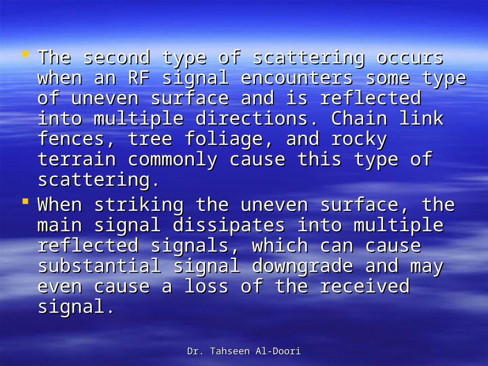
The second type of scattering occurs when The second type of scattering occurs when an RF signal encounters some type of an RF signal encounters some type of uneven surface and is reflected into multiple uneven surface and is reflected into multiple directions. Chain link fences, tree foliage, directions. Chain link fences, tree foliage, and rocky terrain commonly cause this type and rocky terrain commonly cause this type of scattering. of scattering.
When striking the uneven surface, the main When striking the uneven surface, the main signal dissipates into multiple reflected signal dissipates into multiple reflected signals, which can cause substantial signal signals, which can cause substantial signal downgrade and may even cause a loss of downgrade and may even cause a loss of the received signal. the received signal.
Dr. Tahseen Al-DooriDr. Tahseen Al-Doori
ScatteringScattering
Dr. Tahseen Al-DooriDr. Tahseen Al-Doori
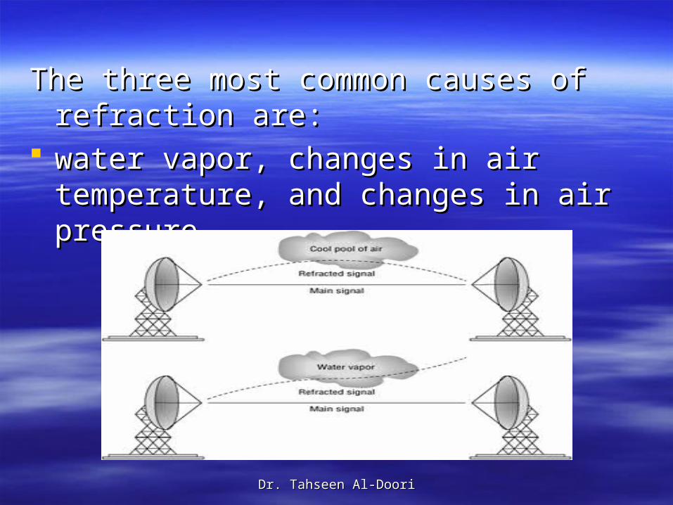
RefractionRefraction
In addition to RF signals being absorbed or In addition to RF signals being absorbed or bounced (via reflection or scattering), if bounced (via reflection or scattering), if certain conditions exist, an RF signal can be certain conditions exist, an RF signal can be bent in a behavior known as bent in a behavior known as refractionrefraction. .
A straightforward definition of refraction is A straightforward definition of refraction is the bending of an RF signal as it passes the bending of an RF signal as it passes through a medium with a different density, through a medium with a different density, thus causing the direction of the wave to thus causing the direction of the wave to change. RF refraction most commonly change. RF refraction most commonly occurs as a result of atmospheric occurs as a result of atmospheric conditions. conditions.
Dr. Tahseen Al-DooriDr. Tahseen Al-Doori
The three most common causes of refraction The three most common causes of refraction are:are:
water vapor, changes in air temperature, water vapor, changes in air temperature, and changes in air pressure. and changes in air pressure.
Dr. Tahseen Al-DooriDr. Tahseen Al-Doori
DiffractionDiffraction
Not to be confused with refraction, another Not to be confused with refraction, another RF propagation behavior exists that also RF propagation behavior exists that also bends the signal; it’s called bends the signal; it’s called diffractiondiffraction. .
Diffraction is the bending of an RF signal Diffraction is the bending of an RF signal around an object (whereas refraction, as around an object (whereas refraction, as you recall, is the bending of a signal as it you recall, is the bending of a signal as it passes through a medium). passes through a medium).
Dr. Tahseen Al-DooriDr. Tahseen Al-Doori
Diffraction is the bending and the spreading Diffraction is the bending and the spreading of an RF signal when it encounters an of an RF signal when it encounters an obstruction. The conditions that must be met obstruction. The conditions that must be met for diffraction to occur depend entirely on for diffraction to occur depend entirely on the shape, size, and material of the the shape, size, and material of the obstructing object as well as the exact obstructing object as well as the exact characteristics of the RF signal, such as characteristics of the RF signal, such as polarization, phase, and amplitude. polarization, phase, and amplitude.
Dr. Tahseen Al-DooriDr. Tahseen Al-Doori
Typically, diffraction is caused by some sort Typically, diffraction is caused by some sort of partial blockage of the RF signal, such as of partial blockage of the RF signal, such as a small hill or a building that sits between a a small hill or a building that sits between a transmitting radio and a receiver. The waves transmitting radio and a receiver. The waves that encounter the obstruction slow down in that encounter the obstruction slow down in speed, which causes them to bend around speed, which causes them to bend around the object. The waves that did not encounter the object. The waves that did not encounter the object maintain their original speed and the object maintain their original speed and do not bend. do not bend.
Example is a rock in a river.Example is a rock in a river.
Dr. Tahseen Al-DooriDr. Tahseen Al-Doori
Loss (Attenuation)Loss (Attenuation)
Loss, also known as Loss, also known as attenuationattenuation, is best , is best described as the decrease of amplitude or described as the decrease of amplitude or signal strength. signal strength.
Try the EMANIM software to view Try the EMANIM software to view Attenuation effect of materials due to Attenuation effect of materials due to absorption. absorption.
Dr. Tahseen Al-DooriDr. Tahseen Al-Doori
Both loss and gain can be gauged in a Both loss and gain can be gauged in a relative measurement of change in power relative measurement of change in power called decibels (dB), which will be discussed called decibels (dB), which will be discussed extensively in extensively in Lesson 3Lesson 3. .
It is important to understand that an RF It is important to understand that an RF signal will also lose amplitude merely as a signal will also lose amplitude merely as a function of distance in what is known as free function of distance in what is known as free space path loss. Also, reflection propagation space path loss. Also, reflection propagation behaviors can produce the negative effects behaviors can produce the negative effects of multipath and as a result cause of multipath and as a result cause attenuation in signal strength.attenuation in signal strength.
Dr. Tahseen Al-DooriDr. Tahseen Al-Doori
Free Space Path LossFree Space Path Loss Due to the laws of physics, an electromagnetic Due to the laws of physics, an electromagnetic
signal will attenuate as it travels despite the lack of signal will attenuate as it travels despite the lack of attenuation caused by obstructions, absorption, attenuation caused by obstructions, absorption, reflections, diffractions, and so on. reflections, diffractions, and so on.
FreeFree space path lossspace path loss is the loss of signal strength is the loss of signal strength caused by the natural broadening of the waves, caused by the natural broadening of the waves, often referred to beam divergence. often referred to beam divergence.
RF signal energy spreads over larger areas as the RF signal energy spreads over larger areas as the signal travels farther away from an antenna, and signal travels farther away from an antenna, and as a result, the strength of the signal attenuates as a result, the strength of the signal attenuates
Dr. Tahseen Al-DooriDr. Tahseen Al-Doori
One way to illustrate free space path loss is to use One way to illustrate free space path loss is to use a balloon analogy. a balloon analogy.
Before a balloon is filled with helium, it remains Before a balloon is filled with helium, it remains small but with a dense rubber thickness. After the small but with a dense rubber thickness. After the balloon is inflated and has grown and spread in balloon is inflated and has grown and spread in size, the rubber becomes very thin. size, the rubber becomes very thin.
RF signals will lose strength in much the same RF signals will lose strength in much the same manner. Luckily, this loss in signal strength is manner. Luckily, this loss in signal strength is logarithmic and not linear, thus the amplitude does logarithmic and not linear, thus the amplitude does not decrease as much in a second segment of not decrease as much in a second segment of equal length as it decreases in the first segment. A equal length as it decreases in the first segment. A 2.4 GHz signal will change in power by about 80 2.4 GHz signal will change in power by about 80 dB after 100 meters but will only lessen another 6 dB after 100 meters but will only lessen another 6 dB in the next 100 meters.dB in the next 100 meters.
Dr. Tahseen Al-DooriDr. Tahseen Al-Doori
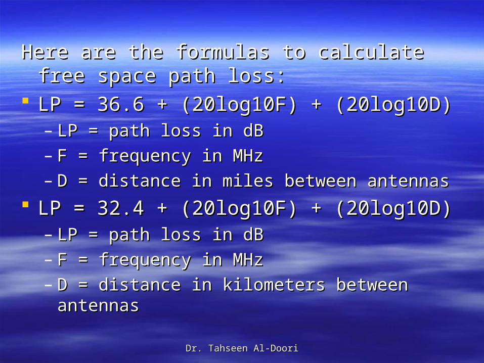
Here are the formulas to calculate free space Here are the formulas to calculate free space path loss:path loss:
LP = 36.6 + (20log10F) + (20log10D)LP = 36.6 + (20log10F) + (20log10D)– LP = path loss in dBLP = path loss in dB– F = frequency in MHzF = frequency in MHz– D = distance in miles between antennasD = distance in miles between antennas
LP = 32.4 + (20log10F) + (20log10D)LP = 32.4 + (20log10F) + (20log10D)– LP = path loss in dBLP = path loss in dB– F = frequency in MHzF = frequency in MHz– D = distance in kilometers between antennasD = distance in kilometers between antennas
Dr. Tahseen Al-DooriDr. Tahseen Al-Doori
The dB calculations will be covered in the The dB calculations will be covered in the next subject which is “RF components and next subject which is “RF components and measurements and mathematics.”measurements and mathematics.”
Dr. Tahseen Al-DooriDr. Tahseen Al-Doori
MultipathMultipath
Multipath is a propagation phenomenon that Multipath is a propagation phenomenon that results in two or more paths of a signal results in two or more paths of a signal arriving at a receiving antenna at the same arriving at a receiving antenna at the same time or within nanoseconds of each other. time or within nanoseconds of each other. Due to the natural broadening of the waves, Due to the natural broadening of the waves, the propagation behaviors of reflection, the propagation behaviors of reflection, scattering, diffraction, and refraction will scattering, diffraction, and refraction will occur. A signal may reflect off an object or occur. A signal may reflect off an object or scatter, refract, or diffract. scatter, refract, or diffract.
Dr. Tahseen Al-DooriDr. Tahseen Al-Doori
MultipathMultipath
Dr. Tahseen Al-DooriDr. Tahseen Al-Doori
ScenarioScenarioWhy Is Free Space Path Loss Important?Why Is Free Space Path Loss Important?
All radio cards have what is known as a receiver sensitivity All radio cards have what is known as a receiver sensitivity level. A radio card can properly interpret and receive a level. A radio card can properly interpret and receive a signal down to a certain fixed amplitude threshold. If a signal down to a certain fixed amplitude threshold. If a radio card receives a signal above its amplitude threshold, radio card receives a signal above its amplitude threshold, the card can differentiate between the signal and other RF the card can differentiate between the signal and other RF noise that is in the background. The background noise is noise that is in the background. The background noise is typically referred to as the typically referred to as the noise floornoise floor..
Once the amplitude of a received signal falls below the Once the amplitude of a received signal falls below the radio card’s threshold, the card can no longer make the radio card’s threshold, the card can no longer make the distinction between the signal and the background noise. distinction between the signal and the background noise. The concept of free space path loss also applies to road The concept of free space path loss also applies to road trips in your car. When you are in a car listening to AM trips in your car. When you are in a car listening to AM radio, eventually you will drive out of range and will no radio, eventually you will drive out of range and will no longer be able to hear the music above the static noise.longer be able to hear the music above the static noise.
Dr. Tahseen Al-DooriDr. Tahseen Al-Doori
When designing both indoor wireless LANS When designing both indoor wireless LANS and outdoor wireless bridge links, you must and outdoor wireless bridge links, you must make sure that the RF signal will not make sure that the RF signal will not attenuate below the receiver sensitivity level attenuate below the receiver sensitivity level of your wireless radio card simply due to of your wireless radio card simply due to free space path loss. free space path loss.
You achieve this goal indoors during a site You achieve this goal indoors during a site survey. An outdoor bridge link requires a survey. An outdoor bridge link requires a series of calculations called a series of calculations called a link budgetlink budget. . (Site surveys and link budgets will be (Site surveys and link budgets will be covered later)covered later)
Dr. Tahseen Al-DooriDr. Tahseen Al-Doori
The time differential between these multiple paths The time differential between these multiple paths is known as the is known as the delay spreaddelay spread. You will learn later . You will learn later that certain spread spectrum technologies are that certain spread spectrum technologies are more tolerant than others of delay spread.more tolerant than others of delay spread.
So what exactly happens when mutipath presents So what exactly happens when mutipath presents itself? itself?
In television signal transmissions, multipath In television signal transmissions, multipath causes a ghost effect with a faded duplicate image causes a ghost effect with a faded duplicate image to the right of the main image. to the right of the main image.
With RF signals, the effects of multipath can be With RF signals, the effects of multipath can be either constructive or destructive. Quite often they either constructive or destructive. Quite often they are very destructive. Due to the differences in are very destructive. Due to the differences in phase of the multiple paths, the combined signal phase of the multiple paths, the combined signal will often attenuate, amplify, or become corrupted. will often attenuate, amplify, or become corrupted. These effects are sometimes called These effects are sometimes called Rayleigh Rayleigh fadingfading
Dr. Tahseen Al-DooriDr. Tahseen Al-Doori
The four results of multipath are as The four results of multipath are as follows:follows:
Downfade Downfade This is decreased signal This is decreased signal strength. When the multiple RF signal paths strength. When the multiple RF signal paths arrive at the receiver at the same time and arrive at the receiver at the same time and are out of phase with the primary wave, the are out of phase with the primary wave, the result is a decrease in signal strength result is a decrease in signal strength (amplitude). Phase differences of between (amplitude). Phase differences of between 121 and 179 degrees will cause downfade.121 and 179 degrees will cause downfade.
Dr. Tahseen Al-DooriDr. Tahseen Al-Doori
Upfade Upfade This is increased signal strength. When This is increased signal strength. When the multiple RF signal paths arrive at the receiver the multiple RF signal paths arrive at the receiver at the same time and are in phase or partially out at the same time and are in phase or partially out of phase with the primary wave, the result is an of phase with the primary wave, the result is an increase in signal strength (amplitude). Smaller increase in signal strength (amplitude). Smaller phase differences of between 0 and 120 degrees phase differences of between 0 and 120 degrees will cause upfade. will cause upfade.
Please understand, however, that the final Please understand, however, that the final received signal can never be stronger than the received signal can never be stronger than the original transmitted signal due to free space path original transmitted signal due to free space path loss.loss.
Dr. Tahseen Al-DooriDr. Tahseen Al-Doori
Nulling Nulling This is signal cancellation. When This is signal cancellation. When the multiple RF signal paths arrive at the the multiple RF signal paths arrive at the receiver at the same time and are 180 receiver at the same time and are 180 degrees out of phase with the primary wave, degrees out of phase with the primary wave, the result can be a complete cancellation of the result can be a complete cancellation of the RF signal.the RF signal.
Dr. Tahseen Al-DooriDr. Tahseen Al-Doori
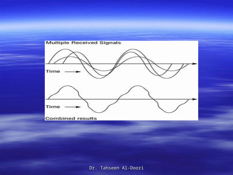
Data Data CorruptionCorruption Intersymbol interference can Intersymbol interference can cause data corruption. Because of the difference cause data corruption. Because of the difference in time between the primary signal and the in time between the primary signal and the reflected signals known as the delay spread, along reflected signals known as the delay spread, along with the fact that there may be multiple reflected with the fact that there may be multiple reflected signals, the receiver can have problems signals, the receiver can have problems demodulating the RF signal’s information. demodulating the RF signal’s information.
The delay spread time differential can cause bits The delay spread time differential can cause bits to overlap with each other and the end result is to overlap with each other and the end result is corrupted data, as seen in corrupted data, as seen in the next slidethe next slide. .
This type of multipath interference is often known This type of multipath interference is often known as as intersymbolintersymbol interference (ISI)interference (ISI)..
Dr. Tahseen Al-DooriDr. Tahseen Al-Doori
Dr. Tahseen Al-DooriDr. Tahseen Al-Doori
So how is a WLAN engineer supposed to So how is a WLAN engineer supposed to deal with all these multipath issues? deal with all these multipath issues?
The use of unidirectional antennas will often The use of unidirectional antennas will often reduce the amount of reflections, and reduce the amount of reflections, and antenna diversity can also be used to antenna diversity can also be used to compensate for the negative effects of compensate for the negative effects of multipath.multipath.
Dr. Tahseen Al-DooriDr. Tahseen Al-Doori
ExerciseExercise
Create the following situations using EMANIM:Create the following situations using EMANIM: Two identical, vertically polarized waves are superposed Two identical, vertically polarized waves are superposed
(you might not see both of them because they cover each (you might not see both of them because they cover each other). The result is a wave having double the amplitude of other). The result is a wave having double the amplitude of the component waves.the component waves.
Two identical, 70 degrees out of phase waves are Two identical, 70 degrees out of phase waves are superposed. The result is a wave with an increased superposed. The result is a wave with an increased amplitude over the component waves.amplitude over the component waves.
Two identical, 140 degree out of phase waves are Two identical, 140 degree out of phase waves are superposed. The result is a wave with a decreased superposed. The result is a wave with a decreased amplitude over the component waves.amplitude over the component waves.
Two identical, vertically polarized waves are superposed. Two identical, vertically polarized waves are superposed. The result is a cancellation of the two waves.The result is a cancellation of the two waves.
Dr. Tahseen Al-DooriDr. Tahseen Al-Doori
Gain (Amplification)Gain (Amplification) also known as also known as amplificationamplification , can best be , can best be
described as the increase of amplitude or described as the increase of amplitude or signal strength. signal strength.
There are two types of gain known as active There are two types of gain known as active gain and passive gain. gain and passive gain.
Active Gain is usually caused by the use of Active Gain is usually caused by the use of an amplifier on the wire that connects the an amplifier on the wire that connects the transceiver to the antenna. transceiver to the antenna.
Passive Gain is accomplished by focusing Passive Gain is accomplished by focusing the RF signal with the use of an antenna. the RF signal with the use of an antenna.
Dr. Tahseen Al-DooriDr. Tahseen Al-Doori
Despite the usual negative effects of Despite the usual negative effects of multipath, it should be reiterated that when multipath, it should be reiterated that when multiple RF signals arrive at the receiver at multiple RF signals arrive at the receiver at the same time and are in phase or partially the same time and are in phase or partially out of phase with the primary wave, the out of phase with the primary wave, the result can be an increase or gain in result can be an increase or gain in amplitude.amplitude.