Embed Size (px)
Citation preview
DRAFT
Concept of Operations Report 1 DRAFT – 10/13/06
October 2006
DRAFT Concept of Operation Report
DRAFT
Concept of Operations Report 2 DRAFT – 10/13/06
1 INTRODUCTION ......................................................................................................................................4 1.1 STAKEHOLDERS...................................................................................................................................4 1.2 CONCESSIONAIRE ARRANGEMENT......................................................................................................5 1.3 DEFINITIONS........................................................................................................................................5 1.4 TUNNEL GEOMETRY............................................................................................................................7
2 TUNNEL AND ROADWAY SYSTEMS ................................................................................................9 2.1 CONTROL ROOMS................................................................................................................................9
2.1.1 Local Operations Control Room...................................................................................................9 2.1.2 Remote Operations Control Room - FDOT District 6 SunGuide TMC ......................................9 2.1.3 Local Secondary Operations Control Room – Watson Island Substation................................10 2.1.4 Primary Point of Control.............................................................................................................10
2.2 COMPUTER SYSTEMS ARCHITECTURE ..............................................................................................11 2.2.1 TSCS System Operation ..............................................................................................................11 2.2.2 Tunnel Mechanical/Electrical/Ancillary Building SCADA System Operation .........................12 2.2.3 Unified Operator Interface .........................................................................................................12
2.3 TRAFFIC SURVEILLANCE AND CONTROL SYSTEMS DESCRIPTION ...................................................13 2.3.1 Closed Circuit Television (CCTV) Camera System....................................................................16 2.3.2 Vehicle Sensor System .................................................................................................................16 2.3.3 Lane Use Signals (LUS) ..............................................................................................................16 2.3.4 Dynamic Message Sign (DMS) System.......................................................................................16 2.3.5 Over Height Vehicle Detectors....................................................................................................16 2.3.6 Portal Closure Traffic Signals ....................................................................................................17 2.3.7 Automatic Traffic Control Gates ................................................................................................17
2.4 MECHANICAL SYSTEMS DESCRIPTION..............................................................................................17 2.4.1 Tunnel Ventilation .......................................................................................................................17 2.4.2 Tunnel Drainage System .............................................................................................................18 2.4.3 Stormwater Drainage System......................................................................................................19 2.4.4 Hydrocarbon Monitoring............................................................................................................19 2.4.5 Fire Suppression..........................................................................................................................19 2.4.6 Ancillary Facility Mechanical Systems.......................................................................................19
2.5 ELECTRICAL SYSTEMS DESCRIPTION ...............................................................................................20 2.5.1 Intrusion Detection/Access Control............................................................................................20 2.5.2 Fire Alarm and Detection............................................................................................................20 2.5.3 Tunnel Lighting............................................................................................................................20 2.5.4 Tunnel Mechanical/Electrical SCADA System...........................................................................20 2.5.5 Communications Systems ............................................................................................................21
2.6 PORTAL FLOOD GATES......................................................................................................................21 3 COORDINATION/ROLES AND RESPONSIBILITIES...................................................................23
3.1 STAKEHOLDER RESPONSIBILITIES ....................................................................................................23 3.1.1 Concessionaire ............................................................................................................................23 3.1.2 Police............................................................................................................................................23 3.1.3 Fire ...............................................................................................................................................24 3.1.4 State Fire Marshall......................................................................................................................24 3.1.5 FDOT ...........................................................................................................................................24
3.2 BOUNDARIES OF OPERATIONS AND MAINTENANCE (O&M)............................................................25 3.2.1 Roadway & Facility O&M Limits ...............................................................................................25 3.2.2 Landscape Maintenance Limits ..................................................................................................26 3.2.3 Incident Response Limits.............................................................................................................27 3.2.4 MOU/Agreements ........................................................................................................................30
DRAFT
Concept of Operations Report 3 DRAFT – 10/13/06
4 EMERGENCY RESPONSE...................................................................................................................31 4.1 INCIDENT COMMAND SYSTEM ..........................................................................................................31 4.2 INCIDENT DETECTION AND RESPONSE TIME POLICY.......................................................................32 4.3 EMERGENCY PULLOUT /ENFORCEMENT AREAS ...............................................................................33 4.4 EVENT PROCESS ................................................................................................................................33
4.4.1 Incident Detection........................................................................................................................33 4.4.2 Confirmation and Gathering of Information .............................................................................33 4.4.3 Notifications.................................................................................................................................36 4.4.4 Response ......................................................................................................................................36
4.5 INCIDENT/EVENT TYPES ...................................................................................................................37 4.6 INCIDENT LEVELS..............................................................................................................................38
4.6.1 Incident Level One.......................................................................................................................39 4.6.2 Incident Level Two.......................................................................................................................40 4.6.3 Incident Level Three ....................................................................................................................41 4.6.4 Incident Level Four......................................................................................................................42 4.6.5 Incident Level Five.......................................................................................................................43
4.7 TUNNEL EVACUATION.......................................................................................................................44 4.8 COMMUNICATIONS ............................................................................................................................44
5 ENFORCEMENT.....................................................................................................................................46 5.1 OVER HEIGHT VEHICLES...................................................................................................................46
5.1.1 Outer Ring Detectors...................................................................................................................46 5.1.2 Inner Ring Detectors ...................................................................................................................46
5.2 CONTROL OF HAZARDOUS MATERIALS/REQUIRED PLACARDED CARGO ........................................46 5.2.1 Surveillance/Detection.................................................................................................................46 5.2.2 Spill Response..............................................................................................................................47 5.2.3 Spill Cleanup................................................................................................................................47
6 LOGGING AND REPORTING.............................................................................................................47
DRAFT
Concept of Operations Report 4 DRAFT – 10/13/06
1 Introduction
The primary objective of this Tunnel Concept of Operations report is to define the overall systems and strategies for operating the tunnel roadway under both normal and emergency modes. This report lays the foundation for the coordinated response to incidents and events by the Concessionaire and the various local fire/life safety agencies. This report will also describe the general day-to-day activities involved with the operation of the Port of Miami (POM) Tunnel and adjacent roadways.
The body of this report contains a general discussion of tunnel systems and their related facilities and equipment. These tunnel systems comprise all of the systems which are necessary for the operation of the tunnel roadways including Traffic Surveillance and Control Systems (TSCS) and Mechanical/Electrical Systems.
The major emphasis behind developing the concept of operations is:
• The identification of system stakeholders as well as the assurance that they will communicate in a common forum and format relative to the system in question;
• The formulation and documentation of a high-level system definition relative to the system in question;
• The foundation for all lower-level sub-system descriptions; • The definition of all major user group and activities. As the preliminary design is advanced this Concept of Operations document will be modified to insure that tunnel roadway and systems design meets the operational needs of all project stakeholders.
1.1 Stakeholders
During the POM Tunnel construction process, a Fire/Life Safety and Traffic Operations and Traffic Management (FLS) working group representing emergency responder interests was established as a steering committee. The FLS Working Group was assembled to pursue the following goals:
• To achieve consensus from emergency response stakeholders about PMT-related safety concerns
• To coordinate their response efforts for PMT incidents
• To obtain their unique perspectives on the PMT features
• To review current FDOT response plans and coordinate with established procedures
• To become familiar with the new tunnel safety and life support equipment
• To establish and conduct ongoing tunnel training for their staffs (mock drills, etc.)
• To insure compliance with all appropriate regulations and codes to maximize safety.
This process will continue throughout the life of the Project as a forum to mitigate design operational issues and maintain agency input into the emergency response and fire/life safety aspects of the Project.
DRAFT
Concept of Operations Report 5 DRAFT – 10/13/06
1.2 Concessionaire Arrangement
The PMT will be designed, built, financed, operated and maintained by a single consortium or Concessionaire under contract to the Florida Department of Transportation (FDOT). The Concessionaire will be responsible for providing an operations and maintenance program including:
• sufficient levels of properly trained personnel,
• on site and off site facilities/garages,
• fleet vehicles,
• computer hardware and software,
• tools,
• customer relations unit, and
• other items as required.
The intent of the operations and maintenance program will be operation and maintenance of a safe, reliable tunnel roadway and facility which maximize public safety, reliability and roadway availability. To this end, the Concessionaire will coordinate, plan and perform the operations and maintenance activities required within this specification in a manner that will provide safety conditions for the maintenance staff and the motorists using the facilities, while minimizing traffic disruptions. The Concessionaire will be compensated for the tunnel operations through an Availability Payment. The Availability Payment will vary depending upon the Concessionaire’s Operations and Maintenance performance.
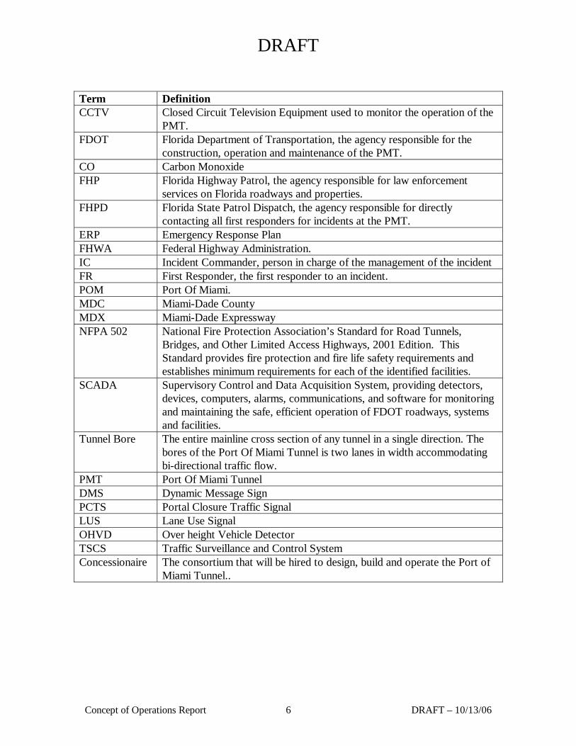
1.3 Definitions
This section has been prepared to provide a common language for the first responders relative to the tunnel and a common understanding of its features, systems and equipment. The Port Of Miami Tunnel has many features and systems that will require the individuals unfamiliar with tunnels to learn. Descriptions are listed alphabetically.
DRAFT
Concept of Operations Report 6 DRAFT – 10/13/06
Term Definition CCTV Closed Circuit Television Equipment used to monitor the operation of the
PMT. FDOT Florida Department of Transportation, the agency responsible for the
construction, operation and maintenance of the PMT. CO Carbon Monoxide FHP Florida Highway Patrol, the agency responsible for law enforcement
services on Florida roadways and properties. FHPD Florida State Patrol Dispatch, the agency responsible for directly
contacting all first responders for incidents at the PMT. ERP Emergency Response Plan FHWA Federal Highway Administration. IC Incident Commander, person in charge of the management of the incident FR First Responder, the first responder to an incident. POM Port Of Miami. MDC Miami-Dade County MDX Miami-Dade Expressway NFPA 502 National Fire Protection Association’s Standard for Road Tunnels,
Bridges, and Other Limited Access Highways, 2001 Edition. This Standard provides fire protection and fire life safety requirements and establishes minimum requirements for each of the identified facilities.
SCADA Supervisory Control and Data Acquisition System, providing detectors, devices, computers, alarms, communications, and software for monitoring and maintaining the safe, efficient operation of FDOT roadways, systems and facilities.
Tunnel Bore The entire mainline cross section of any tunnel in a single direction. The bores of the Port Of Miami Tunnel is two lanes in width accommodating bi-directional traffic flow.
PMT Port Of Miami Tunnel DMS Dynamic Message Sign PCTS Portal Closure Traffic Signal LUS Lane Use Signal OHVD Over height Vehicle Detector TSCS Traffic Surveillance and Control System Concessionaire The consortium that will be hired to design, build and operate the Port of
Miami Tunnel..
DRAFT
Concept of Operations Report 7 DRAFT – 10/13/06
1.4 Tunnel Geometry
The Port Of Miami Tunnel will consist of two bored tunnels under the main cruise shipping channel for the Port of Miami providing connection from the MacArthur Causeway to Dodge Island via Watson Island. The current design calls for each tunnel bore to be approximately 3,800’ from portal to portal. Each bore contains two 12’ wide traffic lanes and nominal 2’ wide shoulders on both sides of the roadway.
The Project consists of three primary components:
• Widening of the MacArthur Causeway Bridge;
• A tunnel connection between Watson Island and Dodge Island; and
• Connections to the Port of Miami (“POM”) roadway system.
The new connection between Watson Island and Dodge Island is designed to run beneath the main shipping channel in Biscayne Bay (Government Cut) to provide direct access to the POM. The approximate length of the Project is three miles. Two tunnels are planned to convey traffic eastbound (to) and westbound (from) the POM.
For both travel directions conceptual designs have shown the roadway ramp connector alignments descending into a depressed “U-wall” section continuing to cut and cover sections and then into the separate tunnel bores. The roadways emerge once again into cut and cover and “U-wall” sections. The complete Project includes the following elements:
• Widening and improvements to the MacArthur Causeway Bridge
• Ramp connections to and from MacArthur Causeway on Watson Island
• Depressed U-wall and cut and cover sections used in the conceptual design to form the transition to the tunnel portals on both Watson Island and the Port of Miami.
• Twin Bored tunnels under the main channel
• Ramp connections and roadway improvements/reconstruction on Dodge Island
• Modified roadway circulation plan with bridge structures on Dodge Island
• Relocation of FEC railroad track and associated facilities on Dodge Island
Surface traffic flow, right-of-way and existing land usage constrain the alignment and configuration on both Watson Island and Dodge Island. The Concessionaire will be obligated to:
1) operate and maintain the O&M Segments as shown in figures 2 and 3 during the Operating Period; and,
2) to subsequently hand-over the O&M Segments in a condition consistent with hand-over requirements that will be set forth in the Concession Agreement.
The Project will contain four, 12-foot lanes in a tunnel expected to consist of two bores, each shown in
DRAFT
Concept of Operations Report 8 DRAFT – 10/13/06
conceptual plans with a total length of approximately 3,900 feet. The tunnels are planned to convey traffic eastbound (to) and westbound (from) the Port. The clearance envelope requires a tunnel with a minimum vertical clearance of 16.5 feet. The total interior diameter will be approximately 36-feet, minimum, for the two lanes of traffic, with allowances for curbs, walkways, ventilation fans, signage, lighting, and other such ancillary features. Due to the geometry of existing roadways and development on both Dodge and Watson islands, the Project limits will necessitate steep grades. It is anticipated that the maximum grade in the Tunnel will be approximately 5%. The Tunnel will be required to comply with egress requirements of NPFA-101, Life Safety Code.
Pressurized emergency cross passages will be provided at intervals of approximately 650’. Fire pull stations, extinguishers and motorist assistance phones will be provided at these cross passage locations and at intervals of approximately 150’.
DRAFT
Concept of Operations Report 9 DRAFT – 10/13/06
2 Tunnel and Roadway Systems
The Port of Miami Tunnel will contain the various mechanical, electrical and traffic surveillance and control systems necessary to support the safe operation of the tunnel and supporting facilities. These systems are summarily described in the following section.
2.1 Control Rooms
The Port of Miami Tunnel will have two fully functional redundant control rooms from which the tunnel can be operated. One will act as the primary point of control while the other will remain in hot standby in the event the primary becomes disabled. These control rooms are designed to be the focal point for all tunnel related activities such as emergency response, tunnel maintenance, and day-to-day operation. Each control room will contain the communications, computer, and video equipment necessary to fully monitor and control the activity within the tunnel and on adjacent roadways.
A local secondary control room will be available at the Watson Island Substation. In the event that the local operations control room becomes disabled, immediate surveillance and control can be implemented from within this facility.
These control room are described in greater detail below.
2.1.1 Local Operations Control Room
The local operations control room will be located within the planned Operations Support Facility (OSF), on Dodge Island. This system supports the two distinct functional systems: the Traffic Surveillance and Control System (TSCS) that provides monitoring and control functionality for the traffic surveillance and control devices and the tunnel mechanical, electrical Supervisory Control and Data Acquisition (SCADA) system that provides monitoring and control functionality for the tunnel mechanical and electrical systems. The local on-site operations control room will be staffed 24-hours a day, seven days a week and contain the following:
• Operations control center computer system for the TSCS
• SCADA computer system
• Workstations and consoles
• Video displays
• Communications: Agency Radios and Telephones
• HVAC
• Fire detection and suppression system
2.1.2 Remote Operations Control Room - FDOT District 6 SunGuide TMC
The remote operations control room will be located at the FDOT, District 6, SunGuide Traffic Management Center and will provide the backup control function for the TSCS, tunnel mechanical, electrical SCADA system in the event the local operations control room is not operational.
The remote operations control room will be designed to support the 24-hour per day 7-days per week continuous staffing requirements of the PMT and will contain the requisite services and facilities necessary to support all control and monitoring functions. The Concessionaire will supply the following items:
DRAFT
Concept of Operations Report 10 DRAFT – 10/13/06
• TSCS computer server.
• Tunnel mechanical/electrical SCADA server.
• Operator computer workstations
• CCTV video display monitors
The Concessionaire will coordinate with the Department to leverage the following services and items that are currently present at the District 6, SunGuide Traffic Management Center.
• Operator workstation consoles
• Video display wall.
• Agency radio and telephone communications.
• HVAC.
• Fire detection and suppression systems.
• Restrooms.
• Spare equipment racks.
2.1.3 Local Secondary Operations Control Room – Watson Island Substation
The local secondary operations control room will be located at the Watson Island Substation. This control room will be immediately available in the event that the primary point of control becomes disabled. The operator and/or local fire/life safety personnel will use this facility as the local point of control to manage an incident for a short period of time or while operations personnel are enroute to the remote operations control room. This control room will support the basic control room function required to support the operation of the tunnel and approach roadways for a limited time.
The local secondary operations control room shall be designed to support the staffing requirements of the PMT and shall contain the requisite services and facilities necessary to support all control and monitoring functions for short periods of time. The Concessionaire shall supply the following:
• Rack mounted operator computer workstation. • Two CCTV video display monitors. • Agency radio and telephone communications. 2.1.4 Primary Point of Control
The primary point of control will reside at the local operations control room for the following reasons:
• Better coordination with the Port of Miami operations.
• Better coordination with tunnel maintenance personnel.
• Better accessibility for agency emergency response personnel.
DRAFT
Concept of Operations Report 11 DRAFT – 10/13/06
The backup control room will reside at the remote operations control room facility. In the event the primary control room is out of service, this facility will serve temporarily as the primary point of control.
2.2 Computer Systems Architecture
The PMT computer systems consist of two distinct functional systems, the TSCS and the tunnel mechanical/electrical/ancillary building SCADA system each will be service by their separate servers.
The TSCS system will be constructed using the FDOT SunGuideSM software or a third party software and will provide the traffic monitoring and control functions necessary to operate the PMT roadways. The TSCS system will be integrated to the FDOT District 6 SunGuideSM TMC either directly as a SunGuideSM software node, or via and external interface.
The tunnel mechanical/electrical/ancillary building SCADA system will be constructed around a robust SCADA software system. This will serve as the central collection and control point for all tunnel mechanical, electrical and ancillary building field hardware.
The Concessionaire will integrate the TSCS and tunnel mechanical/electrical/ancillary building SCADA operator functions into a single unified interface. This unified interface will contain all the screens, reports, data stores and processes required for the tunnel control room operators to perform the required incident management, operating and reporting functions.
The fundamental requirements for the computer system for each of the functional systems are described below.
2.2.1 TSCS System Operation
TSCS operators will use the operator computer workstation and unified operator interface software to monitor and control the TSCS system devices.
The TSCS will use FDOT SunGuideSM compatible hardware devices as much as possible.
Connectivity to the District 6 SunGuideSM TMC will be provided directly via a SunGuideSM software node or indirectly via an external interface with the SunGuideSM system. This external interface will provide realtime data transmission to the FDOT District 6 SunGuideSM TMC for all required traffic monitoring and control devices in a format that is compatible with the SunGuideSM software system.
The TSCS system will provide “monitor and control” functionality for the following systems:
• CCTV
• LUS
• DMS
• PTCS
• Portal Traffic Gates
The TSCS workstation will provide “monitor only” functionality for the following systems:
• Vehicle Detectors
• OHVD
DRAFT
Concept of Operations Report 12 DRAFT – 10/13/06
All TSCS monitoring and control functions will be integrated into the unified operator interface as described below.
2.2.2 Tunnel Mechanical/Electrical/Ancillary Building SCADA System Operation
The SCADA system will contain the computer hardware and software necessary to perform all monitoring and control functions required to support the operation of the tunnel mechanical/electrical/ancillary building equipment and devices.
The tunnel mechanical/electrical/ancillary building SCADA system will provide “monitor and control” functionality for the following systems:
• Tunnel Ventilation
• Intrusion Detection/Access Control
• Tunnel/Stormwater drainage.
• Tunnel lighting.
The tunnel mechanical/electrical/ancillary building SCADA system will provide “monitor only” functionality for the following systems:
• Carbon monoxide monitoring
• Fire alarm and detection
• Fire suppression
• Hydrocarbon monitoring
• Electrical distribution
• Communications systems
• Building systems (HVAC)
All tunnel mechanical/electrical/ancillary building SCADA monitoring and control functions will be integrated into the unified operator interface as described below.
2.2.3 Unified Operator Interface
The Concessionaire will provide a unified operator interface that integrates the TSCS and tunnel mechanical/electrical/ancillary building SCADA operator functions into a single unified interface. This unified interface will contain all the screens, reports, data stores and processes required for the tunnel control room operators to perform the required operating and reporting functions including the following functions:
• TSCS and SCADA alarm notification and acknowledgement.
• TSCS and SCADA system device control.
• Cross platform alarm and device control between the TSCS and SCADA systems.
• Incident and event tracking and logging.
• Incident and event notification logging.
DRAFT
Concept of Operations Report 13 DRAFT – 10/13/06
• The ability for the control center operator to group several secondary alarms or events to a dependant higher level alarm or event.
• TSCS and SCADA system actions tracking and logging.
• Control center operator actions tracking and logging.
• Operational reports generation.
2.3 Traffic Surveillance and Control Systems Description
The TSCS) consists of the hardware and software necessary to monitor and control traffic and improve the safety and quality of traffic flow by preventing or relieving congestion. The primary functions of the system are to provide:
• Efficient movement of traffic on and around the Port of Miami Tunnel roadways.
• Early detection of traffic incidents that cause slowdowns and/or blockages using video based incident detection.
• Motorist alerts to incidents by means of dynamic message signs (DMS), highway advisory radio (HAR), and AM/FM Override.
• Systematic lane control for shifting, or redirecting, traffic through the roadways and tunnels by means of lane use signals (LUS) and DMS.
• Continuous monitoring and logging of traffic conditions using vehicle sensors.
• Communications with emergency services such as fire, police, and first aid.
• Visual traffic monitoring by means of a closed circuit television system (CCTV)
• Improved uniformity and stability of traffic flow, thereby forestalling the onset of congestion
• Reduced potential for rear-end collisions in areas of poor sight distance if congestion is present
• Diversion of freeway traffic to alternate routes to maximize roadway through-put and use of total freeway capacity
The principal benefits of the TSCS are:
• Enhanced motorist safety
• Reduced incident response and clearance time
• Efficient use of available roadway capacity.
The TSCS allows response procedures and strategies to be developed in advance to deal safely with various traffic operations and environmental conditions that will occur. Some of these conditions are reoccurring such as peak hour traffic congestion; some are non-reoccurring, such as accidents. Continuous monitoring of traffic and environmental conditions allows significant changes to be identified
DRAFT
Concept of Operations Report 14 DRAFT – 10/13/06
and the appropriate pre-planned response (i.e. strategy) to be initiated in a timely manner to reduce the severity of the traffic congestion and help mitigate the impact to motorists.
The TSCS will be designed around a quick detect and response time policy. Working in concert with the facility monitoring and control system, the TSCS will assist the Control Room Operator to detect an incident, notify and dispatch appropriate responders, and manage the responder’s access to the incident location.
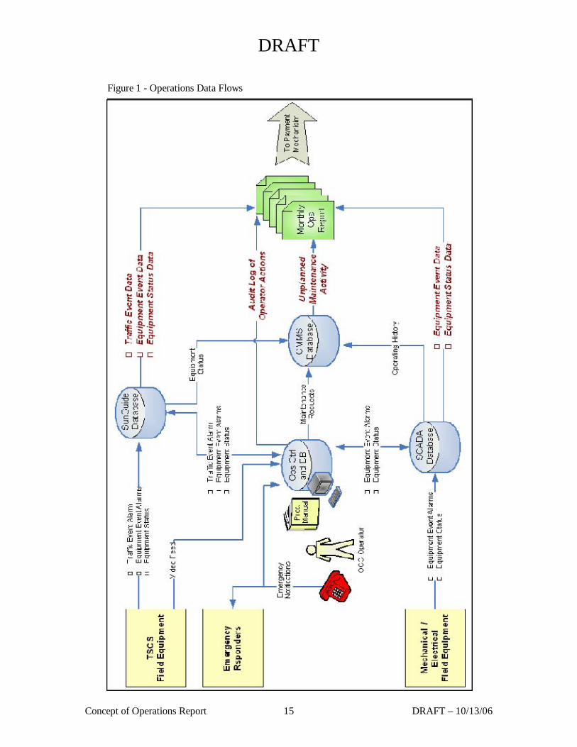
To facilitate this, the TSCS will:
• Gather real time data and video images from surveillance devices and sensors throughout the Port of Miami tunnels and roadways.
• Process gathered data for the purpose of providing notification, coordinating response and supplying event information.
• Control of all TSCS devices in a coordinated fashion, to provide safe and reliable operations and maximize roadway efficiency.
DRAFT
Concept of Operations Report 15 DRAFT – 10/13/06
Figure 1 - Operations Data Flows

DRAFT
Concept of Operations Report 16 DRAFT – 10/13/06
2.3.1 Closed Circuit Television (CCTV) Camera System
Closed circuit television cameras will be installed as part of the TSCS at regular intervals within the tunnel to provide full, overlapping coverage of the tunnel roadway and outside the tunnel to provide full coverage of the approach roadway network. The CCTV cameras will be used to monitor traffic conditions, detect and verify incidents, and verify traveler information on DMS signs and indications on LUS signals. These CCTV cameras will be pan-tilt-zoom color units
The CCTV system will use video detection technology to perform the primary incident detection function for the tunnel and adjacent roadways. The CCTV system is also a critical element of the Tunnel Fire Detection System. As such it will be furnished and installed in compliance with NFPA 502. Digital video recording capabilities will be provided for all CCTV cameras.
2.3.2 Vehicle Sensor System
Vehicle sensors will be installed as part of the TSCS at regular intervals within the tunnel to measure real-time traffic flow, including volume, occupancy, vehicle classification (passenger cars, buses, single unit trucks, multi-trailer trucks, and single combination trucks) and speed. The Vehicle Sensor System will also use data to detect incidents, estimate traffic conditions for dissemination to travelers, share information with other agencies, data archiving for transportation planning and historical data analysis and to support the Availability Payment Mechanism.
2.3.3 Lane Use Signals (LUS)
LUS will be located over each roadway lane at regular intervals throughout the entire length of the tunnel to indicate the status of each travel lane. The LUS system will be used in conjunction with DMS signs to indicate the closure of roadway lane(s) within the tunnel and to channel traffic around single lane incidents and maintenance activities within the tunnel.
2.3.4 Dynamic Message Sign (DMS) System
Dynamic message signs will be installed at regular intervals throughout the tunnel sections and at strategic locations on the roadways approaching the tunnel. Their intention is to provide traveler information to motorists, including traffic advisory, speed control, alternate route messages, information and instructions during emergency situations, and coordination with roadway lane use signals during lane closures and PCTS during tunnel closures. The DMS will support multi-color information display in accordance with the MUTCD. DMS signs will be provided downstream of OHVD locations to display the appropriate over height warning message. Where possible, DMS signs will be co-located with LUS signals on the same support structure, so as to minimize the number of sign structures.
2.3.5 Over Height Vehicle Detectors
The OHVD system will detect vehicles exceeding the Tunnel Vertical Clearance Distance as specified in section 3.2.7 of this RFP. The OHVD detectors will be located on the approaches and entrance ramps to the tunnel roadways. The Detection Height will be defined as the Tunnel Vertical Clearance Distance minus a Safety Factor. An acceptable Safety Factor will be determined by the Concessionaire during the design phase and presented to the Department for approval.
In the event of an interruption of the beams crossing the roadway in the appropriate sequence, the detector controller will activate a downstream DMS message and an audible alarm and strobe light will warn the driver of the over height vehicle and provide instructions. An alarm will also be generated on
DRAFT
Concept of Operations Report 17 DRAFT – 10/13/06
the TSCS computer workstations at both the remote and local on-site operations control rooms.
Outer Ring Detection will be located in advance of the last available decision point where a vehicle can detour and avoid entering the tunnel. Detection at the Outer Ring indicates only a possible over height vehicle incident and serves as an early warning to the operator for identification and monitoring of an over height vehicle approaching the tunnel.
Inner Ring Detection will be located after that decision point, where a vehicle is committed to entering the tunnel. Detection at the Inner Ring represents an actual over height vehicle threat. The inner ring detection locations will also include a physical over height vehicle detection device such as vertical chains, which can be used to identify an over height vehicle in the event the automated OHVD system fails or is inoperable.
An OHVD enforcement plan will be developed to provide enforcement strategies, design detail, and operation of the OHVD system. The enforcement plan will identify pull over and enforcement locations, training for enforcement personnel, and procedures for physically monitoring for over height vehicles at the tunnel portals in the event the OHVD system fails or is inoperable.
2.3.6 Portal Closure Traffic Signals
Portal Closure Traffic Signals (PCTS) will be installed at the entrance portals to control traffic entering each tunnel. The PCTS will be used in conjunction with other TSCS components to indicate closure of the tunnel in the event of an emergency. This will help to prevent additional traffic from entering the tunnel, in accordance with NFPA 502.
When the tunnel is open, PCTS will display a steady green ball. When the tunnel is closed, PCTS will display a steady red ball. A 5 second yellow transition ball will automatically be displayed when switching between the red and green phases, as specified in the MUTCD.
2.3.7 Automatic Traffic Control Gates
Automatic control gates will be used in conjunction with the portal traffic signals to close the tunnel entrance and prevent motorists from entering. These gates will act as a reinforcement to traffic that is queued at the port that the tunnel is closed during incidents that require an extended period of closure.
2.4 Mechanical Systems Description
Various mechanical systems are required for the Port of Miami tunnel to meet building codes, fire life safety standards, and other operational criteria. The mechanical systems include: tunnel ventilation; tunnel fire protection; tunnel drainage; pumping stations; ancillary facility heating, ventilating, and air conditioning; ancillary facility fire protection; ancillary facility plumbing and drainage systems; and any other mechanical systems necessary to meet the criteria specified.
2.4.1 Tunnel Ventilation
The tunnel ventilation system is required to control the air quality within the tunnel. The system will control the buildup of carbon monoxide as well as move smoke out of the tunnel during a fire condition. The tunnel will employ a longitudinal system comprised of ceiling mounted jet fans. The system will be designed to allow for the loss of a pair of jet fans due to heat damage during a fire incident.
The system will be monitored and controlled from the both the Local Operations Control Room and the Remote Operations Control Room, via the tunnel Supervisory Control and Data Acquisition (SCADA)
DRAFT
Concept of Operations Report 18 DRAFT – 10/13/06
system. The Concessionaire will develop the detailed operating procedures to address the following:
• Normal Operating Mode
Under the normal operating mode, the system will control the tunnel pollutant levels such as carbon monoxide (CO), oxides of nitrogen (NOx) and visibility. The system will be operated to adjust the air flow based on CO, NOx and visibility sensors located at regular intervals throughout the tunnel. Sensors will be calibrated through the use of time weighted average measurement data as compared to industry standard exposure durations.
• Fire Emergency Mode
The main purpose of the fire emergency mode is to control heat and smoke during a tunnel fire. The concept is to move the smoke and heat generated by the fire away from motorists that are upstream of the incident location. This action creates a tenable environment for motorists trapped behind the incident and allows them the opportunity to seek an egress from the tunnel.
When a fire event has been detected and confirmed by the tunnel control center operator, the operator shall identify the fire location and then activate the ventilation system in emergency mode for the affected fire location via the SCADA system. The operator’s command will activate the fans the furthest away from the fire so as to not directly disrupt the conditions adjacent to the fire location. The fans will control the smoke and heat behind the fire location and push it out the exit portal of the affected bore. The fans in the unaffected bore will activate in the same direction as those in the affected bore to prevent effluent smoke from being drawn into the unaffected bore. In addition, the cross passageways will automatically pressurize to prevent smoke infiltration. This will create a safe haven for evacuees. This activation of the fire emergency mode will be a one-button operation such that the operator will invoke the fan activation scheme appropriate for the fire location via a single mouse click.
• Other Emergency Mode
The Concessionaire will also be required to develop ventilation system operating procedures that address other circumstances such as terrorist activities.
2.4.2 Tunnel Drainage System
The tunnel drainage system is required to collect and discharge water inflow to the tunnel that results from fire suppression systems, leakage and tunnel washing operations. The tunnel drainage system consists of inlet drains, piping and low point pump stations in each tunnel. The concept of the tunnel drainage system is for the water to be collected via drains or inlet grates and then for the water to flow inside pipes via gravity to the tunnel low point pump station. The low point pump station has a settling basin, a wet well and a pump room. The water will flow into the settling basin to settle out heavy grit and articulates. The settling basin normally is full of water and any additional water will displace the existing water to flow via a weir into the wet well. The wet well will be fitted with three pumps that will operate automatically based upon the water levels in the wet well. The pumps will discharge the wet well water to a transfer facility on Watson Island, where it will be pumped to the local sanitary system.
The settling basin and wet well will be equipped with a hydrocarbon monitoring system that detects the presence of hydrocarbon vapors. The settling basin and wet well will also have a ventilation system that is used to purge the hydrocarbon levels in the settling basin and wet well to safe levels.
The tunnel low point pump stations will operate automatically under most circumstances; however,
DRAFT
Concept of Operations Report 19 DRAFT – 10/13/06
specific procedures are required to address certain circumstances such as high water levels, roadway spills, fuel spills, or excessive flooding. The Concessionaire will be required to develop the procedures for these circumstances, and other circumstances that may require the operation of the tunnel low point pumps stations.
2.4.3 Stormwater Drainage System
The stormwater drainage system is required to collect and discharge stormwater from the surface roadways. The stormwater drainage system consists of inlet drains, piping and stormwater pump stations. The concept of the stormwater drainage system to collect water via drains and pipes that are connected to the stormwater pump stations. The stormwater is gathered in the drains and flows inside pipes via gravity to the stormwater pump stations. The stormwater flows into the wet well where heavy grit and particulates are settled out. . The stormwater pump station fitted with pumps that will operate automatically based upon the water levels in the wet well. The pumps will discharge the stormwater to a permitted discharge location.
The stormwater pump stations will operate automatically under most circumstances; however, specific procedures are required to address certain circumstances such as high water levels, roadway spills, fuel spills, or excessive flooding. The Concessionaire will be required to develop the procedures for these circumstances, and other circumstances that may require the operation of the tunnel low point pumps stations.
2.4.4 Hydrocarbon Monitoring
The pump station settling basins and wet wells will be equipped with a hydrocarbon monitoring system that detects the presence of hydrocarbon vapors. The settling basin and wet well will also have a ventilation system that is automatically will operate to purge the hydrocarbon levels in the settling basin and wet well to safe levels. The concessionaire will develop procedures to address sustained high hydrocarbon levels in the pump station settling basin and wet well areas. The procedures shall include the steps necessary to address the situation.
2.4.5 Fire Suppression
The tunnel fire suppression system consists of a fire standpipe system, and fire extinguishers. The standpipe system consists of a water supply system, piping, and hose connection stations located throughout the tunnel. The standpipe system will be an automatic wet system that is filled with water at a sufficient pressure to provide the required flow and pressure at each hose connection location. The Concessionaire shall develop operating procedures to operate and maintain the standpipe system at the required pressure.
The tunnel may also be equipped with a manually operated deluge type of fire suppression system that consists of a water supply system, piping and fixed nozzles in the tunnel. The system, if provided, will require specific operating procedures that will be developed with the input and approval of the local fire department.
2.4.6 Ancillary Facility Mechanical Systems
The ancillary facilities require various systems to provide an appropriate and safe environment for the various spaces within the facilities. The systems include heating ventilating and air conditioning, fire protection, and plumbing and drainage systems. The various heating, ventilating, and air conditioning systems may include the following equipment: humidifiers, dehumidifiers, exhaust fans, supply fans, air
DRAFT
Concept of Operations Report 20 DRAFT – 10/13/06
conditioning units, and air handling units. The Concessionaire will develop operating procedures to monitor and control the heating ventilating and air conditioning equipment/systems.
The ancillary facility fire protection systems will consist of sprinkler systems and clean agent systems for control room and computer rooms. The Concessionaire shall develop procedures for clean agent fire suppression systems in ancillary facilities.
2.5 Electrical Systems Description The electrical distribution systems includes a 13.2kV redundant electrical service at both ends of the tunnel; complete 480V distribution system, including supplies to pumping stations and flood gates; a standby 480V electrical system consisting of diesel fueled generators and uninterruptible power supplies; complete lighting systems for the tunnel, buildings, and roadways; special systems including but not limited to Telephone, CCTV, AM/FM/HAR Radio Systems, Fire Detection and Alarm, Access Control and Intrusion Detection, Vibration Monitoring; and any other electrical systems necessary to meet the criteria specified. 2.5.1 Intrusion Detection/Access Control
TBD
2.5.2 Fire Alarm and Detection
The fire detection system (FDS) will consist of a distributed, addressable system comprised of microprocessor based, intelligent type local fire alarm control panels (FACPs), and associated peripherals. The FACPs shall connect to the supervisory control and data acquisition (SCADA) system, and be supervised in accordance with NFPA72 by a licensed proprietary or central station facility which would then contact the Miami and Miami-Dade Fire Department after confirmation of an incident within the tunnel or approaching roadway.
Installation and locations of all fire alarm initiating devices will comply with the requirements of NFPA 72, and the appropriate Fire Departments.
2.5.3 Tunnel Lighting
Lighting for the Project will be provided for the tunnels, approach roadways and ancillary buildings. The tunnel lighting will be designed to provide adequate daytime illumination in the entrance portion of the tunnels, so that motorists can drive a vehicle safely and efficiently at the design speed. Overall, the design criteria is based on a symmetrical lighting concept using fluorescent and high pressure sodium light sources contained in linear and point source water-tight fixture housings. The aesthetical aspects of the tunnel lighting system are identified in the Architectural specifications.
2.5.4 Tunnel Mechanical/Electrical SCADA System
A comprehensive supervisory control and data acquisition (SCADA) system will be established to provide monitoring and control functionality for the mechanical electrical tunnel systems.
The architecture of the SCADA system will employ a fail-safe network topology. Each programmable logic controller (PLC) shall be designed with a redundant “hot-standby” configuration, capable of a
DRAFT
Concept of Operations Report 21 DRAFT – 10/13/06
seamless transfer of data upon a failure of the main processor. Additionally, the programmable logic controller shall be equipped with redundant power supplies.
The SCADA system will employ a universal remote input/output network protocol, allowing different networkable devices the ability to communicate with the programmable logic controller. Remote input/output (RIO) cabinets shall be distributed throughout the facility in order to minimize “hard-wired” cable runs between field devices and the SCADA system. Each remote input/output cabinet will be designed to accommodate the required number of points for digital input (DI), digital output (DO), analog input (AI), and other data modules as needed, with an additional fifty percent (50%) spare of each point type (DI, DO, AI, etc). The remote input/output cabinet shall be housed in a NEMA 4X cabinet sized to accommodate the required number of input/output modules (including spares).
The design of major mechanical and electrical equipment will incorporate provisions for communication, control, and indication, via normally-open and normally-closed contacts, transducers, and auxiliary relays, to provide control/indication.
2.5.5 Communications Systems
The PMT will contain the voice and data communications systems necessary to provide full communications within the tunnel for both humans and tunnel equipment. The communications system includes the following elements.
• The Telephone System will provide voice communication support for internal and external voice communication for staff, and related support personnel. The telephone system will include support for Emergency Telephones which will be located at regular interval along the tunnel roadway.
• The Agency Radio system will enable communication with and between incident responders, and other agency staff. This system will support the following agency radio frequencies at a minimum.
• The AM/FM Rebroadcast system will provide the ability for the rebroadcast of normal AM/FM broadcasts as well as the preemptive override broadcast of emergency information to motorist in the tunnel over a standard AM/FM radio. This override capability will be used in fire/life safety situations where an immediate danger to motorist is detected and the delivery of explicit emergency instructions is required.
• The communications backbone is vital to all other communications systems. This backbone will provide doubly redundant communications pathways to allow voice, alarm, status and video information to be provided to the control centers. This backbone will consist of fiber-optic cables that run through each tunnel bore and connect to FDOT’s fiber backbone on either end of the tunnel. This backbone will be designed to allow redundant data flows through each tunnel bore such that full capability is retained if the backbone is severed in any one location.
2.6 Portal Flood Gates The PMT will be equipped with portal flood gates located at the end of each tunnel bore. The portal flood gates are to be used to protect the tunnel during storm events that have a significant storm surge that could flood the tunnel and cause significant damage to the equipment and systems located in the tunnel. The Concessionaire will develop a Hurricane Response Plan that includes procedures with the details and criteria to determine when to close the tunnel portal flood gates. The Hurricance Response Plan

DRAFT
Concept of Operations Report 22 DRAFT – 10/13/06
will take into account the reports from the National Oceanic and Atmospheric Administration’s National Weather Service and National Hurricane Center. The Concessionaire also will develop specific procedures for the actual process of closing of the tunnel flood gates. These procedures shall include the public notification process, and detailed steps regarding the closing process. The Concessionaire will also develop detailed procedures to open the tunnel flood gates and the roadway to the public. The Department reserves the right to direct the Concessionaire to close the portal flood gates at any time.
DRAFT
Concept of Operations Report 23 DRAFT – 10/13/06
3 Coordination/Roles and Responsibilities
3.1 Stakeholder Responsibilities
Each agency responding to an incident at the tunnel has specific priorities and responsibilities. On complex incidents, some of these roles may overlap and the priorities of some of some agencies may affect the ability of other agencies to perform their duties. Each agency’s responsibility is briefly described below.
3.1.1 Concessionaire
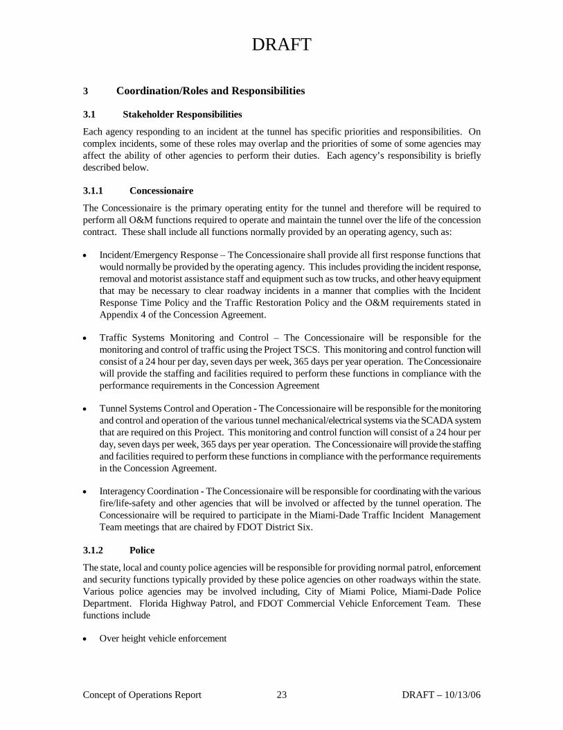
The Concessionaire is the primary operating entity for the tunnel and therefore will be required to perform all O&M functions required to operate and maintain the tunnel over the life of the concession contract. These shall include all functions normally provided by an operating agency, such as:
• Incident/Emergency Response – The Concessionaire shall provide all first response functions that would normally be provided by the operating agency. This includes providing the incident response, removal and motorist assistance staff and equipment such as tow trucks, and other heavy equipment that may be necessary to clear roadway incidents in a manner that complies with the Incident Response Time Policy and the Traffic Restoration Policy and the O&M requirements stated in Appendix 4 of the Concession Agreement.
• Traffic Systems Monitoring and Control – The Concessionaire will be responsible for the monitoring and control of traffic using the Project TSCS. This monitoring and control function will consist of a 24 hour per day, seven days per week, 365 days per year operation. The Concessionaire will provide the staffing and facilities required to perform these functions in compliance with the performance requirements in the Concession Agreement
• Tunnel Systems Control and Operation - The Concessionaire will be responsible for the monitoring and control and operation of the various tunnel mechanical/electrical systems via the SCADA system that are required on this Project. This monitoring and control function will consist of a 24 hour per day, seven days per week, 365 days per year operation. The Concessionaire will provide the staffing and facilities required to perform these functions in compliance with the performance requirements in the Concession Agreement.
• Interagency Coordination - The Concessionaire will be responsible for coordinating with the various fire/life-safety and other agencies that will be involved or affected by the tunnel operation. The Concessionaire will be required to participate in the Miami-Dade Traffic Incident Management Team meetings that are chaired by FDOT District Six.
3.1.2 Police
The state, local and county police agencies will be responsible for providing normal patrol, enforcement and security functions typically provided by these police agencies on other roadways within the state. Various police agencies may be involved including, City of Miami Police, Miami-Dade Police Department. Florida Highway Patrol, and FDOT Commercial Vehicle Enforcement Team. These functions include
• Over height vehicle enforcement
DRAFT
Concept of Operations Report 24 DRAFT – 10/13/06
• Hazardous materials restrictions enforcement
• Incident response
• General traffic control
• Traffic
• General Roadway Patrols and Enforcement
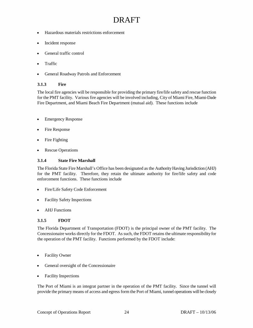
3.1.3 Fire
The local fire agencies will be responsible for providing the primary fire/life safety and rescue function for the PMT facility. Various fire agencies will be involved including, City of Miami Fire, Miami-Dade Fire Department, and Miami Beach Fire Department (mutual aid). These functions include
• Emergency Response
• Fire Response
• Fire Fighting
• Rescue Operations
3.1.4 State Fire Marshall
The Florida State Fire Marshall’s Office has been designated as the Authority Having Jurisdiction (AHJ) for the PMT facility. Therefore, they retain the ultimate authority for fire/life safety and code enforcement functions. These functions include
• Fire/Life Safety Code Enforcement
• Facility Safety Inspections
• AHJ Functions
3.1.5 FDOT
The Florida Department of Transportation (FDOT) is the principal owner of the PMT facility. The Concessionaire works directly for the FDOT. As such, the FDOT retains the ultimate responsibility for the operation of the PMT facility. Functions performed by the FDOT include:
• Facility Owner
• General oversight of the Concessionaire
• Facility Inspections
The Port of Miami is an integrat partner in the operation of the PMT facility. Since the tunnel will provide the primary means of access and egress form the Port of Miami, tunnel operations will be closely
DRAFT
Concept of Operations Report 25 DRAFT – 10/13/06
coordinated with Port operations. The Port of Miami will be the primary point of contact for all tunnel related events and activities that will have an impact on Port operations. Functions performed by the Port of Miami include:
• Port Traffic Operations
• Port Security
• Incident Management Coordination
3.2 Boundaries of Operations and Maintenance (O&M)
The Port of Miami Tunnel will be available 24 hours per day, 7 days per week, 365 days per year. The Concessionaire will provide operations and maintenance staff for these hours of operation. Periodic closures of the tunnel bores will be required due to planned maintenance, unplanned maintenance repairs/activities, vehicular accidents, weather, or other circumstances that require tunnel closure.
The Concessionaire’s operations and maintenance staff, and any subcontractors, will comply with Florida Statute 311.12, Seaport Security Standards. The Concessionaire’s operations and maintenance procedures will be developed in accordance with these requirements and will include the necessary provisions and requirements for compliance with this security standard.
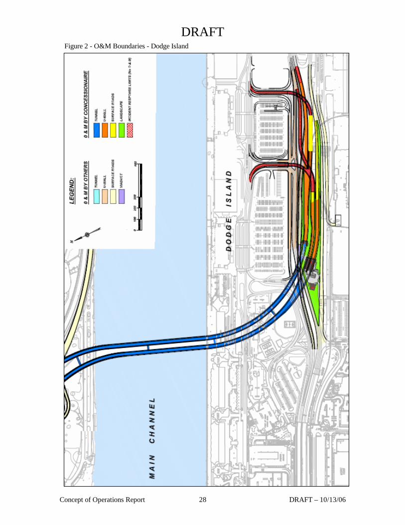
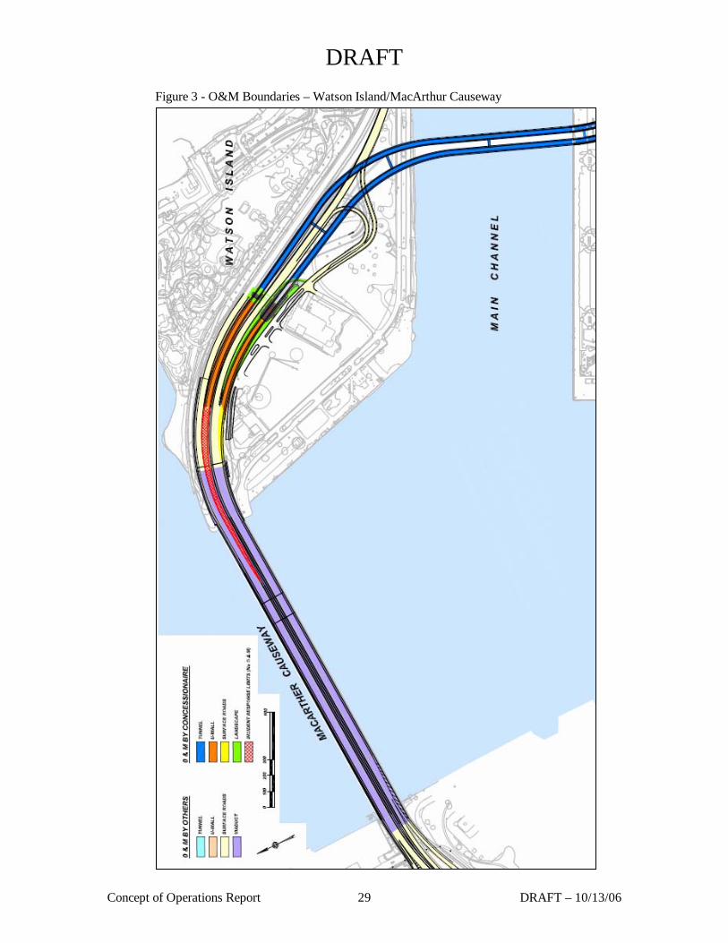
The Concessionaire will be responsible for various categories of operations and maintenance over differing geographical boundaries such as Roadway & Facility Operations & Maintenance, Landscape Maintenance, and Incident Response. Figures 2& 3 show the preliminary limits of responsibility for the Concessionaire across each category of O&M. The Concessionaire’s final design layout will determine the actual O&M boundaries, however the intent and concept of the O&M boundaries is defined within the limits described herein.
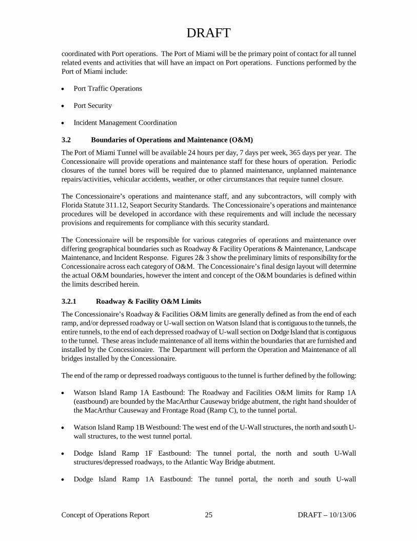
3.2.1 Roadway & Facility O&M Limits
The Concessionaire’s Roadway & Facilities O&M limits are generally defined as from the end of each ramp, and/or depressed roadway or U-wall section on Watson Island that is contiguous to the tunnels, the entire tunnels, to the end of each depressed roadway of U-wall section on Dodge Island that is contiguous to the tunnel. These areas include maintenance of all items within the boundaries that are furnished and installed by the Concessionaire. The Department will perform the Operation and Maintenance of all bridges installed by the Concessionaire.
The end of the ramp or depressed roadways contiguous to the tunnel is further defined by the following:
• Watson Island Ramp 1A Eastbound: The Roadway and Facilities O&M limits for Ramp 1A (eastbound) are bounded by the MacArthur Causeway bridge abutment, the right hand shoulder of the MacArthur Causeway and Frontage Road (Ramp C), to the tunnel portal.
• Watson Island Ramp 1B Westbound: The west end of the U-Wall structures, the north and south U-wall structures, to the west tunnel portal.
• Dodge Island Ramp 1F Eastbound: The tunnel portal, the north and south U-Wall structures/depressed roadways, to the Atlantic Way Bridge abutment.
• Dodge Island Ramp 1A Eastbound: The tunnel portal, the north and south U-wall
DRAFT
Concept of Operations Report 26 DRAFT – 10/13/06
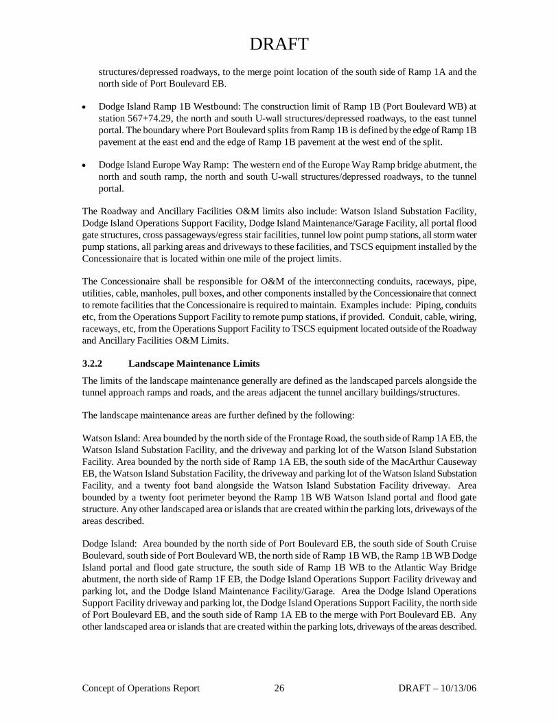
structures/depressed roadways, to the merge point location of the south side of Ramp 1A and the north side of Port Boulevard EB.
• Dodge Island Ramp 1B Westbound: The construction limit of Ramp 1B (Port Boulevard WB) at station 567+74.29, the north and south U-wall structures/depressed roadways, to the east tunnel portal. The boundary where Port Boulevard splits from Ramp 1B is defined by the edge of Ramp 1B pavement at the east end and the edge of Ramp 1B pavement at the west end of the split.
• Dodge Island Europe Way Ramp: The western end of the Europe Way Ramp bridge abutment, the north and south ramp, the north and south U-wall structures/depressed roadways, to the tunnel portal.
The Roadway and Ancillary Facilities O&M limits also include: Watson Island Substation Facility, Dodge Island Operations Support Facility, Dodge Island Maintenance/Garage Facility, all portal flood gate structures, cross passageways/egress stair facilities, tunnel low point pump stations, all storm water pump stations, all parking areas and driveways to these facilities, and TSCS equipment installed by the Concessionaire that is located within one mile of the project limits.
The Concessionaire shall be responsible for O&M of the interconnecting conduits, raceways, pipe, utilities, cable, manholes, pull boxes, and other components installed by the Concessionaire that connect to remote facilities that the Concessionaire is required to maintain. Examples include: Piping, conduits etc, from the Operations Support Facility to remote pump stations, if provided. Conduit, cable, wiring, raceways, etc, from the Operations Support Facility to TSCS equipment located outside of the Roadway and Ancillary Facilities O&M Limits.
3.2.2 Landscape Maintenance Limits
The limits of the landscape maintenance generally are defined as the landscaped parcels alongside the tunnel approach ramps and roads, and the areas adjacent the tunnel ancillary buildings/structures.
The landscape maintenance areas are further defined by the following:
Watson Island: Area bounded by the north side of the Frontage Road, the south side of Ramp 1A EB, the Watson Island Substation Facility, and the driveway and parking lot of the Watson Island Substation Facility. Area bounded by the north side of Ramp 1A EB, the south side of the MacArthur Causeway EB, the Watson Island Substation Facility, the driveway and parking lot of the Watson Island Substation Facility, and a twenty foot band alongside the Watson Island Substation Facility driveway. Area bounded by a twenty foot perimeter beyond the Ramp 1B WB Watson Island portal and flood gate structure. Any other landscaped area or islands that are created within the parking lots, driveways of the areas described.
Dodge Island: Area bounded by the north side of Port Boulevard EB, the south side of South Cruise Boulevard, south side of Port Boulevard WB, the north side of Ramp 1B WB, the Ramp 1B WB Dodge Island portal and flood gate structure, the south side of Ramp 1B WB to the Atlantic Way Bridge abutment, the north side of Ramp 1F EB, the Dodge Island Operations Support Facility driveway and parking lot, and the Dodge Island Maintenance Facility/Garage. Area the Dodge Island Operations Support Facility driveway and parking lot, the Dodge Island Operations Support Facility, the north side of Port Boulevard EB, and the south side of Ramp 1A EB to the merge with Port Boulevard EB. Any other landscaped area or islands that are created within the parking lots, driveways of the areas described.
DRAFT
Concept of Operations Report 27 DRAFT – 10/13/06
3.2.3 Incident Response Limits
The incident response limits generally are the areas described within the Roadway & Facility O&M limits plus the connected tunnel approach and exit roadways to their nearest intersection or termination point. The rational in having the incident response limits extend to the nearest intersection or termination point is to minimize the impact of incidents on directly connected roadways as response by others could be delayed potentially impacting tunnel operation. Ideally the Concessionaire would have Incident Response limits identical to the Roadway & Facility O&M limits, however since the Department will perform the O&M for all bridges constructed by the Concessionaire, this type of continuity is not possible.
The Incident Response limits include all of the areas described in the Roadway & Facilities O&M limits and additional roadway areas further defined as:
Watson Island Ramp 1B WB: from west end of the Ramp 1B WB Roadway & Facilities O&M limits to the location where the tunnel exit lanes are fully merged into the MacArthur Causeway WB lanes (approximate station is 195+50)
Dodge Island Ramp 1F EB (Atlantic Way Ramp & South Cruise Boulevard Ramp): from the east end of the Ramp 1F EB Roadway & Facilities O&M limits to the location where Atlantic Way meets the south side of North Cruise Boulevard, and from the east end of the Ramp 1F EB Roadway & Facilities O&M limits to the location where the South Cruise Boulevard ramp meets Port Cruise Boulevard EB.
Dodge Island Europe Way Ramp: from the intersection of the Europe Way Ramp and North Cruise Boulevard to the east end of the Europe Way Ramp Roadway & Facilities O&M limits.
DRAFT
Concept of Operations Report 28 DRAFT – 10/13/06
Figure 2 - O&M Boundaries - Dodge Island
DRAFT
Concept of Operations Report 29 DRAFT – 10/13/06
Figure 3 - O&M Boundaries – Watson Island/MacArthur Causeway
DRAFT
Concept of Operations Report 30 DRAFT – 10/13/06
3.2.4 MOU/Agreements
Various memorandums of understanding (MOU) and interagency agreements will be required for the operation of the PMT facility. These will be in the areas of maintenance, enforcement, operations and emergency response. The Concessionaire will be required to identify these agreements and participate in the development of all required MOUs and interagency agreements.
DRAFT
Concept of Operations Report 31 DRAFT – 10/13/06
4 Emergency Response
Incidents in the Port of Miami Tunnel are detected by the operators, who are continuously monitoring tunnel operations via closed circuit video equipment (CCTV) located throughout the tunnel and along the approaches. In addition, incidents can be reported by tunnel users by use of pull stations and emergency call boxes located throughout the tunnel. CO detectors will indicate elevated CO levels from traffic congestion. Once an incident has been verified, the appropriate response crews are dispatched.
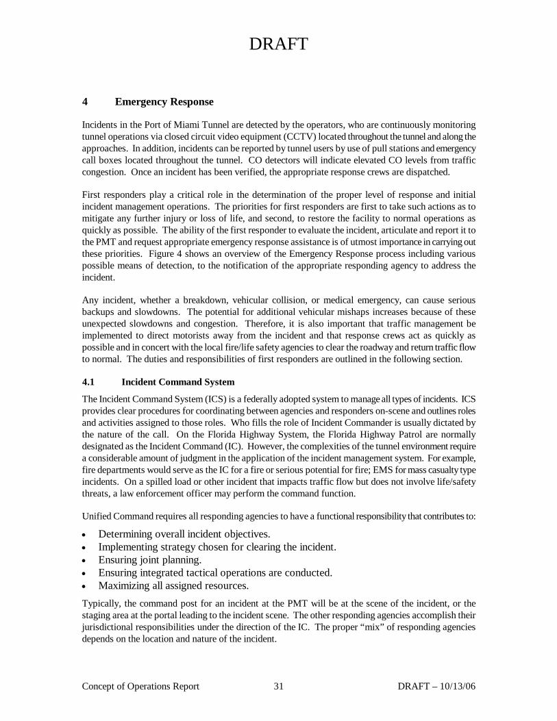
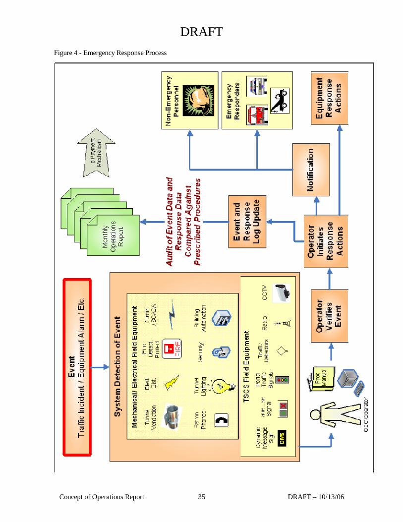
First responders play a critical role in the determination of the proper level of response and initial incident management operations. The priorities for first responders are first to take such actions as to mitigate any further injury or loss of life, and second, to restore the facility to normal operations as quickly as possible. The ability of the first responder to evaluate the incident, articulate and report it to the PMT and request appropriate emergency response assistance is of utmost importance in carrying out these priorities. Figure 4 shows an overview of the Emergency Response process including various possible means of detection, to the notification of the appropriate responding agency to address the incident.
Any incident, whether a breakdown, vehicular collision, or medical emergency, can cause serious backups and slowdowns. The potential for additional vehicular mishaps increases because of these unexpected slowdowns and congestion. Therefore, it is also important that traffic management be implemented to direct motorists away from the incident and that response crews act as quickly as possible and in concert with the local fire/life safety agencies to clear the roadway and return traffic flow to normal. The duties and responsibilities of first responders are outlined in the following section.
4.1 Incident Command System
The Incident Command System (ICS) is a federally adopted system to manage all types of incidents. ICS provides clear procedures for coordinating between agencies and responders on-scene and outlines roles and activities assigned to those roles. Who fills the role of Incident Commander is usually dictated by the nature of the call. On the Florida Highway System, the Florida Highway Patrol are normally designated as the Incident Command (IC). However, the complexities of the tunnel environment require a considerable amount of judgment in the application of the incident management system. For example, fire departments would serve as the IC for a fire or serious potential for fire; EMS for mass casualty type incidents. On a spilled load or other incident that impacts traffic flow but does not involve life/safety threats, a law enforcement officer may perform the command function.
Unified Command requires all responding agencies to have a functional responsibility that contributes to:
• Determining overall incident objectives. • Implementing strategy chosen for clearing the incident. • Ensuring joint planning. • Ensuring integrated tactical operations are conducted. • Maximizing all assigned resources. Typically, the command post for an incident at the PMT will be at the scene of the incident, or the staging area at the portal leading to the incident scene. The other responding agencies accomplish their jurisdictional responsibilities under the direction of the IC. The proper “mix” of responding agencies depends on the location and nature of the incident.
DRAFT
Concept of Operations Report 32 DRAFT – 10/13/06
Incident Coordination is established by the highest-ranking field authority at the scene that has jurisdiction for the incident.
• Each agency should operate with its own incident management structure, under the overall coordination of the IC.
• Each agency determines who their senior field representative is and informs the IC immediately upon arrival.
• On occasion, an agency superior may arrive on-scene. In most cases, they do not serve as the new senior representative or IC, but use their influence to assist their agency’s efforts to clear the incident.
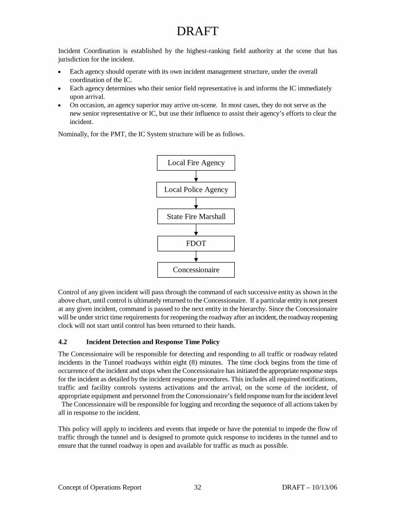
Nominally, for the PMT, the IC System structure will be as follows.
Control of any given incident will pass through the command of each successive entity as shown in the above chart, until control is ultimately returned to the Concessionaire. If a particular entity is not present at any given incident, command is passed to the next entity in the hierarchy. Since the Concessionaire will be under strict time requirements for reopening the roadway after an incident, the roadway reopening clock will not start until control has been returned to their hands.
4.2 Incident Detection and Response Time Policy
The Concessionaire will be responsible for detecting and responding to all traffic or roadway related incidents in the Tunnel roadways within eight (8) minutes. The time clock begins from the time of occurrence of the incident and stops when the Concessionaire has initiated the appropriate response steps for the incident as detailed by the incident response procedures. This includes all required notifications, traffic and facility controls systems activations and the arrival, on the scene of the incident, of appropriate equipment and personnel from the Concessionaire’s field response team for the incident level The Concessionaire will be responsible for logging and recording the sequence of all actions taken by all in response to the incident.
This policy will apply to incidents and events that impede or have the potential to impede the flow of traffic through the tunnel and is designed to promote quick response to incidents in the tunnel and to ensure that the tunnel roadway is open and available for traffic as much as possible.
Local Fire Agency
Local Police Agency
State Fire Marshall
FDOT
Concessionaire
DRAFT
Concept of Operations Report 33 DRAFT – 10/13/06
4.3 Emergency Pullout /Enforcement Areas
Emergency Pullout/Enforcement Areas will be located near each tunnel entrance portal to provide for Concessionaire and agency emergency response and enforcement activities. These pullouts will be a minimum of 16’ wide and 200’ long and located in the right shoulder of the roadway so as not to create any hazard to general vehicular traffic. All pullouts shall include signage that indicates they are for official use only.
A means for emergency vehicles to access each tunnel in the contra-flow (against traffic) direction will also be provided. This contra-flow access points will be provided at locations that can easily be accessed by emergency vehicles when responding to an incident in the tunnel. These contra-flow access locations will be designed and located in such a manner so as not to create any hazard to general vehicular traffic, prevent the accidental use by said general vehicular traffic, and include signage that indicates they are for official use only.
The final location and configuration of these Emergency Contra-flow Tunnel Access points and Emergency Pullout/Enforcement Areas will be determined by the Concessionaire and the Department in conjunction with local fire/life safety agencies. All signs, barriers and other safety elements shall conform to AASHTO and MUTCD requirements for similar type facilities.
4.4 Event Process
The Control Center Operator has four basic tasks with regard to incident response as described below:
4.4.1 Incident Detection
Incidents will be detected and verified in multiple ways:
• By the CCTV camera system: Traffic incidents shall be automatically detected by the video based detection system using motion detection technology. The control room operator shall receive an incident alarm via the operator workstation and be prompted to respond to the incident.
• By an operator: The TSCS provides the operator with the ability to scan the road network for incidents using the CCTV system and video display at the operations control rooms.
• Facility system alarm: The facility control system shall generate alarms for hazardous conditions, such as high CO concentrations and fire that the control room operator shall immediately evaluate.
• By an external source: External sources, such as motorists, police and maintenance staff, shall also detect incidents.
Regardless of how the incident is detected, the Control Center Operator is responsible for the following tasks:
4.4.2 Confirmation and Gathering of Information
Operator confirmation shall be accomplished primarily through the use of the CCTV camera system. Design of the system shall facilitate the confirmation process by automatically providing the operator with location information, such as mile marker or other relevant location information, that be confirmed via CCTV camera coverage or by response staff in the field. Design of the system shall also consider automatic camera selection, where CCTV coverage of a detected incident is automatically provided from the nearest camera in the vicinity of the incident and displayed at the operator’s workstation console.

DRAFT
Concept of Operations Report 34 DRAFT – 10/13/06
For facilities related events which cannot be verified with the CCTV camera system, confirmation that the event that generated the alarm continues to persist shall be made through communications with on-site emergency response personnel.
DRAFT
Concept of Operations Report 35 DRAFT – 10/13/06
Figure 4 - Emergency Response Process
DRAFT
Concept of Operations Report 36 DRAFT – 10/13/06
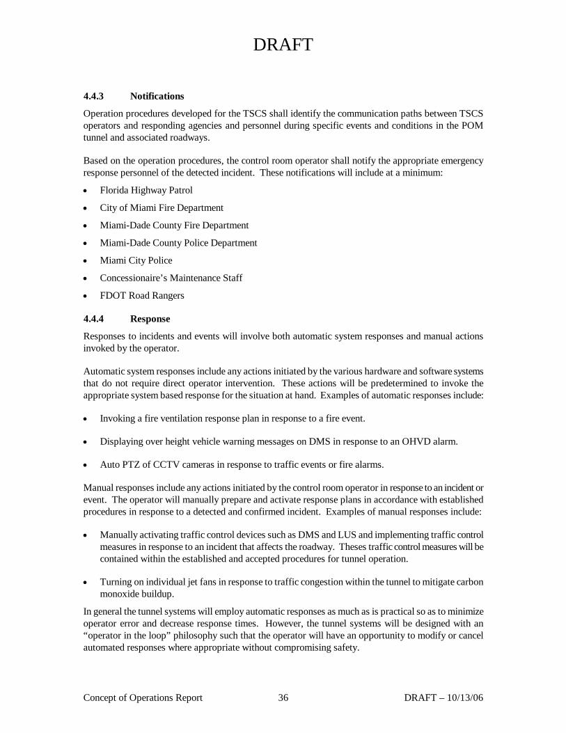
4.4.3 Notifications
Operation procedures developed for the TSCS shall identify the communication paths between TSCS operators and responding agencies and personnel during specific events and conditions in the POM tunnel and associated roadways.
Based on the operation procedures, the control room operator shall notify the appropriate emergency response personnel of the detected incident. These notifications will include at a minimum:
• Florida Highway Patrol
• City of Miami Fire Department
• Miami-Dade County Fire Department
• Miami-Dade County Police Department
• Miami City Police
• Concessionaire’s Maintenance Staff
• FDOT Road Rangers
4.4.4 Response
Responses to incidents and events will involve both automatic system responses and manual actions invoked by the operator.
Automatic system responses include any actions initiated by the various hardware and software systems that do not require direct operator intervention. These actions will be predetermined to invoke the appropriate system based response for the situation at hand. Examples of automatic responses include:
• Invoking a fire ventilation response plan in response to a fire event.
• Displaying over height vehicle warning messages on DMS in response to an OHVD alarm.
• Auto PTZ of CCTV cameras in response to traffic events or fire alarms.
Manual responses include any actions initiated by the control room operator in response to an incident or event. The operator will manually prepare and activate response plans in accordance with established procedures in response to a detected and confirmed incident. Examples of manual responses include:
• Manually activating traffic control devices such as DMS and LUS and implementing traffic control measures in response to an incident that affects the roadway. Theses traffic control measures will be contained within the established and accepted procedures for tunnel operation.
• Turning on individual jet fans in response to traffic congestion within the tunnel to mitigate carbon monoxide buildup.
In general the tunnel systems will employ automatic responses as much as is practical so as to minimize operator error and decrease response times. However, the tunnel systems will be designed with an “operator in the loop” philosophy such that the operator will have an opportunity to modify or cancel automated responses where appropriate without compromising safety.
DRAFT
Concept of Operations Report 37 DRAFT – 10/13/06
4.5 Incident/Event Types
The types of incidents that can occur at the Port Of Miami Tunnel can be grouped into three major categories as follows:
• Roadway Events
− Disabled Vehicle(s)
− Vehicle Collision
− Hazardous Cargo Spill
− Non-Hazardous Cargo Spill
− Structural Failure
− Medical Emergency
− Hurricane/Severe Weather
− Over height Vehicle Threat/Strike
− Fire/Smoke
− Loss of Tunnel Lighting
− Excessive CO Concentrations In Tunnel
• System Events
− Fire/Life Safety System Failure
− Mechanical System Failure
− Electrical Distribution System Failure
− Communications System Failure
− Traffic Surveillance and Control System Failure
• Security Violations
− Intrusion Detection Alarms
− Bomb Threat
The levels of incidents range from Level 1 (minor incidents) to Level 5 (major incidents with closure of both tunnel bores). The appropriate procedures for PMT operators and responders, based on the level of a particular incident, are described in the following sections.

DRAFT
Concept of Operations Report 38 DRAFT – 10/13/06
4.6 Incident Levels
Defined incident levels help to guide the response to incidents at the tunnel. These levels are intended to simplify and guide consistent responses based on the level of impact to the tunnel and specific nature of the incident. Common use of levels also helps responders and those responsible for disseminating information to immediately grasp the magnitude of the incident.
The following tables are meant as a guide to help quantify the magnitude of an incident, the resources required to respond and measures appropriate for managing it. They are not intended to determine the actual response to an incident. A detailed response plan will be developed by the tunnel operator during the design phase of the project in conjunction with the various fire/life-safety response agencies.
The level of incident response will be dictated by the severity of the incident as classified in Table 1. Each incident level is described in greater detail in the subsequent sections.
Table 1 – Roadway Incident/Event Level Summary Level Tunnel Closures
Required Normal Traffic Restoration Time
1 Breakdown, minor accident (no injuries) or non-hazardous material spill or debris in one travel lane.
None 20 minutes
2 Single vehicle accident (with injuries) and, one travel lane blocked.
Single Lane or Possible Single Bore
35 minutes
3 Multiple vehicle accident. Multiple injuries. All travel lanes blocked. No major threat of explosion, fire or hazards.
Single Bore 60 minutes
4 Multiple vehicle accident. Multiple injuries/fatalities. Entire single tunnel bore roadway blocked. Potential threat of fire, explosion, hazardous airborne material, and water contamination. May require evacuation of motorists.
Both Bores 120 minutes
5 Conditions same as level four except that all travel lanes in one direction, plus one or more travel lanes in the opposite direction must be closed.
Both Bores 240 minutes
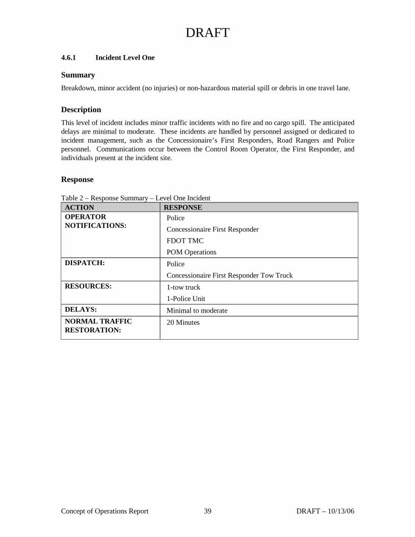
DRAFT
Concept of Operations Report 39 DRAFT – 10/13/06
4.6.1 Incident Level One
Summary Breakdown, minor accident (no injuries) or non-hazardous material spill or debris in one travel lane.
Description This level of incident includes minor traffic incidents with no fire and no cargo spill. The anticipated delays are minimal to moderate. These incidents are handled by personnel assigned or dedicated to incident management, such as the Concessionaire’s First Responders, Road Rangers and Police personnel. Communications occur between the Control Room Operator, the First Responder, and individuals present at the incident site.
Response Table 2 – Response Summary – Level One Incident
ACTION RESPONSE OPERATOR NOTIFICATIONS:
Police Concessionaire First Responder FDOT TMC POM Operations
DISPATCH: Police Concessionaire First Responder Tow Truck
RESOURCES: 1-tow truck 1-Police Unit
DELAYS: Minimal to moderate NORMAL TRAFFIC RESTORATION:
20 Minutes
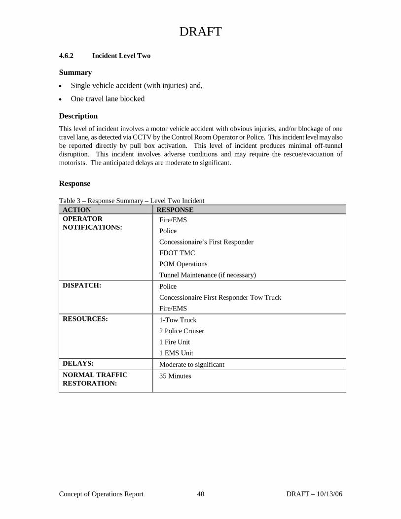
DRAFT
Concept of Operations Report 40 DRAFT – 10/13/06
4.6.2 Incident Level Two
Summary
• Single vehicle accident (with injuries) and,
• One travel lane blocked
Description This level of incident involves a motor vehicle accident with obvious injuries, and/or blockage of one travel lane, as detected via CCTV by the Control Room Operator or Police. This incident level may also be reported directly by pull box activation. This level of incident produces minimal off-tunnel disruption. This incident involves adverse conditions and may require the rescue/evacuation of motorists. The anticipated delays are moderate to significant.
Response Table 3 – Response Summary – Level Two Incident
ACTION RESPONSE OPERATOR NOTIFICATIONS:
Fire/EMS Police Concessionaire’s First Responder FDOT TMC POM Operations Tunnel Maintenance (if necessary)
DISPATCH: Police Concessionaire First Responder Tow Truck Fire/EMS
RESOURCES: 1-Tow Truck 2 Police Cruiser 1 Fire Unit 1 EMS Unit
DELAYS: Moderate to significant NORMAL TRAFFIC RESTORATION:
35 Minutes
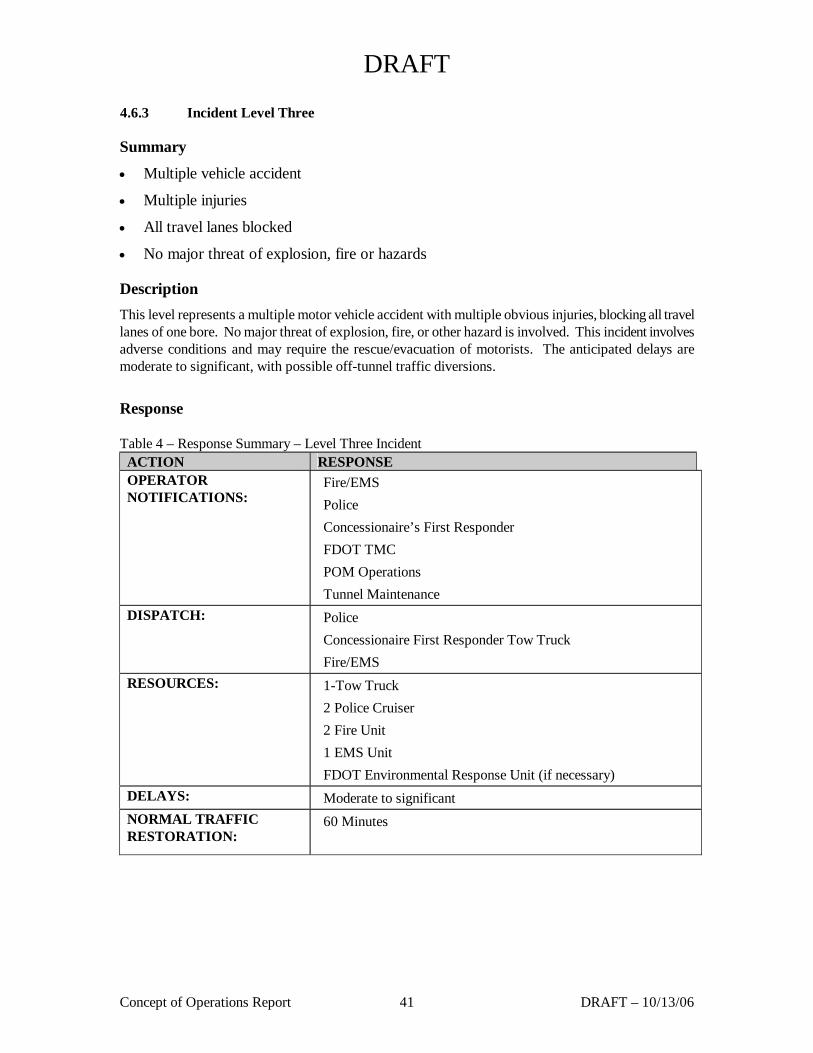
DRAFT
Concept of Operations Report 41 DRAFT – 10/13/06
4.6.3 Incident Level Three
Summary
• Multiple vehicle accident
• Multiple injuries
• All travel lanes blocked
• No major threat of explosion, fire or hazards
Description This level represents a multiple motor vehicle accident with multiple obvious injuries, blocking all travel lanes of one bore. No major threat of explosion, fire, or other hazard is involved. This incident involves adverse conditions and may require the rescue/evacuation of motorists. The anticipated delays are moderate to significant, with possible off-tunnel traffic diversions.
Response Table 4 – Response Summary – Level Three Incident
ACTION RESPONSE OPERATOR NOTIFICATIONS:
Fire/EMS Police Concessionaire’s First Responder FDOT TMC POM Operations Tunnel Maintenance
DISPATCH: Police Concessionaire First Responder Tow Truck Fire/EMS
RESOURCES: 1-Tow Truck 2 Police Cruiser 2 Fire Unit 1 EMS Unit FDOT Environmental Response Unit (if necessary)
DELAYS: Moderate to significant NORMAL TRAFFIC RESTORATION:
60 Minutes
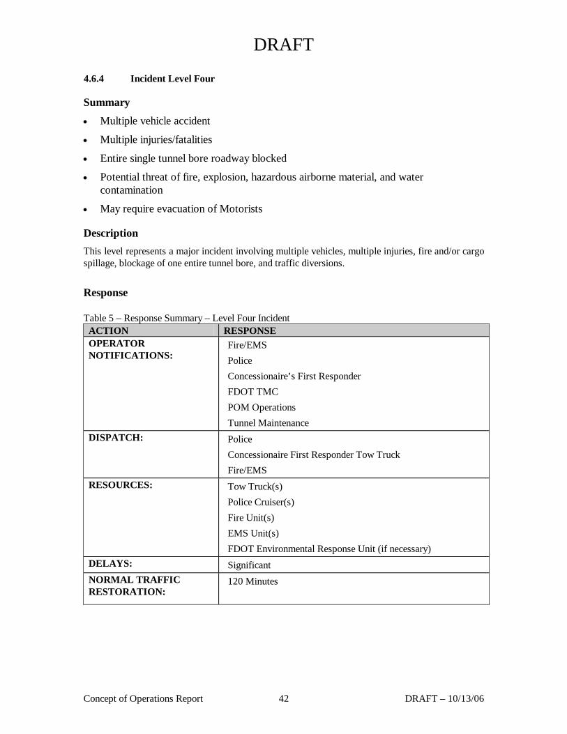
DRAFT
Concept of Operations Report 42 DRAFT – 10/13/06
4.6.4 Incident Level Four
Summary
• Multiple vehicle accident
• Multiple injuries/fatalities
• Entire single tunnel bore roadway blocked
• Potential threat of fire, explosion, hazardous airborne material, and water contamination
• May require evacuation of Motorists
Description This level represents a major incident involving multiple vehicles, multiple injuries, fire and/or cargo spillage, blockage of one entire tunnel bore, and traffic diversions.
Response Table 5 – Response Summary – Level Four Incident
ACTION RESPONSE OPERATOR NOTIFICATIONS:
Fire/EMS Police Concessionaire’s First Responder FDOT TMC POM Operations Tunnel Maintenance
DISPATCH: Police Concessionaire First Responder Tow Truck Fire/EMS
RESOURCES: Tow Truck(s) Police Cruiser(s) Fire Unit(s) EMS Unit(s) FDOT Environmental Response Unit (if necessary)
DELAYS: Significant NORMAL TRAFFIC RESTORATION:
120 Minutes
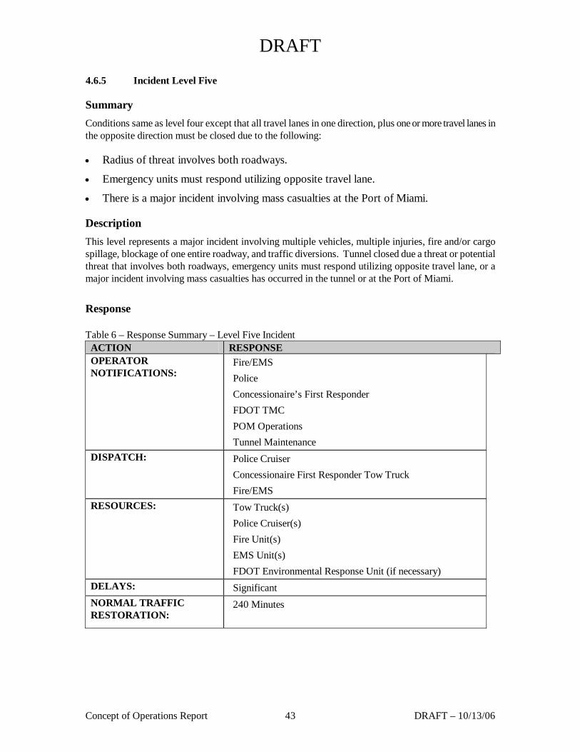
DRAFT
Concept of Operations Report 43 DRAFT – 10/13/06
4.6.5 Incident Level Five
Summary Conditions same as level four except that all travel lanes in one direction, plus one or more travel lanes in the opposite direction must be closed due to the following:
• Radius of threat involves both roadways.
• Emergency units must respond utilizing opposite travel lane.
• There is a major incident involving mass casualties at the Port of Miami.
Description This level represents a major incident involving multiple vehicles, multiple injuries, fire and/or cargo spillage, blockage of one entire roadway, and traffic diversions. Tunnel closed due a threat or potential threat that involves both roadways, emergency units must respond utilizing opposite travel lane, or a major incident involving mass casualties has occurred in the tunnel or at the Port of Miami.
Response Table 6 – Response Summary – Level Five Incident
ACTION RESPONSE OPERATOR NOTIFICATIONS:
Fire/EMS Police Concessionaire’s First Responder FDOT TMC POM Operations Tunnel Maintenance
DISPATCH: Police Cruiser Concessionaire First Responder Tow Truck Fire/EMS
RESOURCES: Tow Truck(s) Police Cruiser(s) Fire Unit(s) EMS Unit(s) FDOT Environmental Response Unit (if necessary)
DELAYS: Significant NORMAL TRAFFIC RESTORATION:
240 Minutes
DRAFT
Concept of Operations Report 44 DRAFT – 10/13/06
4.7 Tunnel Evacuation
In the event that the tunnel is blocked due to a fire, traffic accident, or other major incident motorist may need to abandon their vehicles and evacuate the tunnel on foot. Under these conditions, traffic in the affected tunnel will likely be stopped for a considerable distance behind the incident. Therefore, the primary means of egress for evacuation is considered to be back up the roadway away for the incident location. The tunnel ventilation system is designed to facilitate this primary evacuation route by pushing any smoke or noxious fumes that may be present in the tunnel away from the area behind the incident, in the downstream direction, to create a tenable environment for motorist.
A secondary mean of evacuation is provided via the tunnel cross passages. These cross-passages, located approximately every 650 feet through out the tunnels, will allow motorists that have abandoned their vehicles to cross to the unaffected tunnel. They will be designed with doors and a ventilation system that prevents the inflow of smoke or other noxious fumes into the cross passage to create a tenable environment for motorists. Tunnel cross passages will be provided with the following:
• Roadway level egress pathways, clearances, ramps, and areas of refuge adjacent to each bore in compliance with NFPA 502
• Telephones within the areas of refuge
• Fire department connections (siamese) and extinguishers adjacent to each bore in compliance with NFPA 502
• Illuminated exit lights & lighting fixtures.
The Concessionaire will be required to work with the local fire/life safety agencies to develop a comprehensive evacuation plan for the tunnel.
4.8 Communications
The PMT will be equipped with various communications systems and devices to support communications with motorists in the tunnel and between the various fire/life safety agencies that will be responding to incidents and events.
The means for communicating with the motorists in the tunnels are provided via:
− DMS
− AM/FM Overrride/HAR
− Emergency Telephones
A two-way FM radio communication system will be provided for continuous radio communication for for selected agency frequencies such as police, fire, and EMS.
The system will receive externally generated radio signals at the respective agency’s frequency, and re-transmit them inside the tunnel. It will also receive signals generated within the tunnel, and re-transmit them to the respective agency’s radio transmission network. The transmission will be via antenna and receiving/transmitting equipment located in either the operations support facility, or the Watson Island substation building.

DRAFT
Concept of Operations Report 45 DRAFT – 10/13/06
The following agencies will be incorporated into the design of the radio system at a minimum:
• Miami-Dade County Fire Rescue Department
• City of Miami Fire Rescue Department
• Florida Highway Patrol
• Miami EMS
• Florida DOT
• Miami Police Department
• Miami-Dade Police Department
• Nationwide Government Interoperability
The Concessionaire, in coordination with the Fire/Life Safety Committee, will be required to determine the final list of agency radio frequencies to be served in the tunnels.
DRAFT
Concept of Operations Report 46 DRAFT – 10/13/06
5 Enforcement
The Port of Miami Tunnel presents some unique challenges with regard to enforcement. As with all tunnels, the two major concerns are over height vehicles and hazardous materials. Other enforcement issues include speed, passing restrictions and tunnel closure violations. The following section details the enforcement issues and plans surrounding these items.
5.1 Over Height Vehicles
The nominal tunnel vertical clearance for the Port of Miami Tunnel will be 16 feet 6 inches. The tunnel will be equipped with an over height vehicle detection system that will detect and warn vehicles exceeding the established detection height as specified in Section 3, Design and Construction Requirements. Equally important is the enforcement side of the equation and the plan for extracting the over height vehicle from the tunnel portal area. This response and enforcement process is described below.
5.1.1 Outer Ring Detectors
For the outer ring detector on MacArthur Causeway, the OHVD message will instruct the driver to merge left and continue toward Miami Beach. The outer ring detectors located at the truck gate on Dodge Island will have dedicated OHVD and DMS on each lane. Over height vehicles will be instructed to use the Port Boulevard Bridge instead of the port of Miami Tunnel.
5.1.2 Inner Ring Detectors
The DMS message for the inner ring detectors located on the tunnel off ramp, will instruct the driver to pull to the right side of the road, stop and await the arrival of the police. This action will block a single traffic lane, but will not completely stem the flow of traffic since this two lane ramp is fed by a single lane of traffic. The Control Room Operator will use the DMS upstream of the stopped vehicle to merge traffic to the left lane of the ramp. The responding Concessionaire and police personnel will secure the site and setup a physical taper to close the right lane upstream of the stopped vehicle. On-scene personnel will then measure the height of the vehicle to determine if it was actually over height. Vehicles that measure over height will be detained in the right lane until such a time as it can be safely backed up the ramp. This may require that the vehicle be detained through the peak period and could last for several hours. Vehicles that measure under the established detection height will be released and allowed to continue through the tunnel.
5.2 Control of Hazardous Materials/Required Placarded Cargo
Hazardous materials and cargos will be prohibited from this tunnel. As outlined in NFPA 502, the tunnel operator will coordinate with appropriate local agencies including the Department and the Port of Miami to develop a final policy document that describes the hazardous material policy for the tunnel facility. The facility and surrounding roadways will be fitted with the appropriate signage to indicate that hazardous materials are not allowed.
5.2.1 Surveillance/Detection The Concessionaire will develop operating and response procedures detailing the step-by-step actions that will be performed by their personnel in the event that hazardous cargos enter the tunnel. These procedures will include training in traffic surveillance techniques that include the visual detection of hazardous materials placards.
DRAFT
Concept of Operations Report 47 DRAFT – 10/13/06
5.2.2 Spill Response The Concessionaire will develop step-by-step procedures detailing the actions to be performed by their personnel in the event of a hazardous material or cargo spill in the tunnel facility or any of the other roadways that are within their area of authority. These procedures will include the detection, notification, dispatch and response to an incident of this type by the operator’s personnel in coordination with local fire/life safety responders. 5.2.3 Spill Cleanup The Concessionaire will develop a contact list of contractors qualified and licensed to cleanup and properly dispose of hazardous materials that may be spilled in the tunnel roadways.
6 Logging and Reporting
The Concessionaire ‘s control center operator will log all incident and event data . This data will contain the following information at a minimum: • Start Time and Date of the Incident/Event • Type of Incident/Event • # of Vehicles Involved (if traffic incident) • Trucks Involved • Injuries • Fire • Hazardous/Bulk Materials • Arrival time of responders on-scene • Responder actions