Embed Size (px)
Citation preview

DRAFT Damages Assessment Plan Addendum for Transition Zone Assessment at the Madison County Mines Site
March 2016
Prepared by:
John Weber, U.S. Fish and Wildlife Service
Kathy Rangen, Missouri Department of Natural Resources
Southeast Missouri Lead Mining District
Natural Resource Damage Assessment and Restoration

Table of Contents 1.0 Introduction……………………………………………………………………………......1
2.0 Site Information ............................................................................................................................... 1
2.1 Location ..................................................................................................................................... 1
2.2 Contaminants of Concern ......................................................................................................... 2
3.0 Data Quality Objectives ................................................................................................................... 3
3.1 Problem Statement ..................................................................................................................... 3
3.2 Planning Team ........................................................................................................................... 3
3.3 Conceptual Site Model (CSM) ................................................................................................... 3
3.4 Study Questions ......................................................................................................................... 4
3.5 Study Boundary ......................................................................................................................... 5
3.6 Sampling Design ........................................................................................................................ 5
3.7 Field Sampling Decisions .......................................................................................................... 6
4.0 Field Activities ..................................................................................................................................... 8
4.1 Soil Sampling ............................................................................................................................ 8
4.1.1 In-Situ XRF Analysis ................................................................................................ 8
4.2 Sample Conditioning and Analysis ......................................................................................... 11
4.3 Number of Samples, and Container and Preservation………………..………….……..11
4.4 Chain-of-Custody ..................................................................................................................... 11
5.0 Quality Control .................................................................................................................................... 12
5.1 Field Decontamination ............................................................................................................ 12
5.2 Quality Assurance/Quality Control (QA/QC) Samples .......................................................... 12
5.2.1 Equipment Rinsate Blank ........................................................................................ 12
5.2.2 XRF Precision Samples ....................................................................................... 13
5.2.3 Laboratory QC .................................................................................................... 13
6.0 Investigation Derived Wastes (IDW) Plan ........................................................................................... 13
7.0 Site Safety ............................................................................................................................................. 14
References ................................................................................................................................................... 14

Figures
Figure 1. The Southeast Missouri Lead Mining District ................................................................ 2
Figure 2. Anschutz Mine................................................................................................................. 7
Figure 3. In-Situ XRF Analysis Within Sampling Units .............................................................. 10
Appendix A – Health and Safety Plan
Appendix B – XRF Standard Operating Procedures
Appendix C– Sampling Area Field Sheet
Appendix D– Soil Sample Log Form

LIST OF ACRONYMS
ALAD Delta-Aminolevulinic Acid Dehydrase
CERCLA Comprehensive Environmental Response Compensation and Liability Act
COC Chain of Custody
CSM Conceptual Site Model
DI Deionized Water
DQO Data Quality Objective
ESP Environmental Services Program
IDW Investigation Derived Waste
MCMS Madison County Mine Site
MDNR Missouri Department of Natural Resources
NPL National Priorities List
NRDA Natural Resources Damage Assessment
OLB Old Lead Belt
OPA Oil Pollution Act
PPE Personal Protective Equipment
QA/QC Quality Assurance / Quality Control
QAPP Quality Assurance Project Plan
SEMOLMD Southeast Missouri Lead Mining District
SOP Standard Operating Procedure
TZSS Transition Zone Sampling Study
USEPA United States Environmental Protection Agency
USFWS United States Fish and Wildlife Service
XRF X-ray Fluorescence

This page intentionally left blank

1
1.0 Introduction
The Comprehensive Environmental Response, Compensation, and Liability Act of 1980
(CERCLA), as amended, and the Oil Pollution Act (OPA) provide for the restoration of natural
resources lost or injured by hazardous substance releases (§107(f)) and discharges of oil (§1006)
and require the designation of certain Federal and State officials to act on behalf of the public as
Trustees for natural resources. The Missouri Department of Natural Resources (MDNR) together
with the U.S. Fish and Wildlife Service (USFWS), acting as Trustees, are conducting a Natural
Resource Damage Assessment in the Southeast Missouri Lead Mining District (SEMOLMD), at
the Madison County Mine Site (MCMS).
This document is an Addendum to the Madison County Mine Site Damage Assessment Plan
Addendum, available at:
http://www.fws.gov/Midwest/es/ec/nrda/SEMONRDA/pdf/MadisonCountyDAPAddendum12May2015.pdf.
The purpose of conducting the Transition Zone Sampling Study (TZSS) in the MCMS as
described in this Addendum is to obtain soils metal concentration data from areas near and
around the chat/tailings piles, where data is lacking and that are involved in the MCMS natural
resource damage assessment.
2.0 Site Information
2.1 Location The work to be conducted for this TZSS will take place in the MCMS, at the Anschutz Mine site,
also known as the “Madison Mine”, which is approximately 75 miles southwest of St. Louis in
Madison County. The MCMS lies within the SEMOLMD, which occupies the greater part of
southeast Missouri (see Figure 1).
The Anschutz Mine occupies approximately 265 acres and is located near the city of
Fredericktown, MO. The Anschutz property has been used for mining since the mid-1840s.
The St. Louis Smelting Company and Refining Division of the National Lead Company (NLC –
late NL Industries, Inc.) operated the mine from 1942 to 1961, building a cobalt refinery in 1952.

2
The Anschutz Mining Corporation purchased the property from local property owners in 1979
after a spike in the price of cobalt. Cobalt was recovered by re-processing tailings at the site.
The U.S. Environmental Protection Agency (USEPA) listed the MCMS on the National
Priorities List (NPL) in 2003.
Figure 1. The Southeast Missouri Lead Mining District
2.2 Contaminants of Concern
The hazardous substances released at the MCMS include cadmium (CAS # 7440439), lead (CAS
# 7439921), zinc (CAS # 7440666), copper (CAS # 7440-50-8), cobalt (CAS # 7440-48-4) and
nickel (CAS # 7440-02-0). These compounds or mixtures have been identified under CERCLA
§l01 (14) as hazardous substances (40 CFR §302, Table 302.4). Lead (Pb) is by far the most

3
common contaminant of concern at the MCMS and will be the primary analyte of concern for the
current study, though concentrations of other metals will be recorded and compared to
Ecological Soil Screening Level values.
3.0 Data Quality Objectives
Field work for TZSS and associated analyses will be conducted in accordance with the Quality
Assurance Project Plan (QAPP) for Natural Resource Damages, Revision 3, April, 2011
(MDNR, 2011). The QAPP describes the general data quality objectives (DQO) for site
assessment investigations conducted by the Trustees. Those DQOs specific to this project are
described below.
3.1 Problem Statement
To develop a better understanding of soil metals contamination levels and spatial extent
surrounding the tailings areas at the Anschutz property on which to base natural resource injury
determination and quantification.
3.2 Planning Team
The planning team includes staff from the MDNR Hazardous Waste Program and the Columbia,
Missouri Ecological Services Field Office of the U.S. Fish & Wildlife Service.
3.3 Conceptual Site Model (CSM) Metals can be released from mining/milling activities in a
number of ways. Transport mechanisms for metals to the terrestrial environment include direct
deposition from mining and milling wastes, migration via surface water and sediment transport
from fugitive air emissions from stockpiled wastes. The primary transport mechanism for metals
to the terrestrial environment surrounding the tailings impoundments is assumed to be via wind.
Therefore, a higher soil concentration and a further extent of influence are expected in the
predominant downwind directions at each impoundment.
Erosion and deposition to surrounding soils of toxic heavy metals is of concern to the Trustees.
Heavy metals exposure through the ingestion of contaminated soils has been documented to

4
cause measurable injury to natural resources under the jurisdiction of the Federal trustees,
especially ground feeding migratory songbirds (Beyer 2013; Stratus 2014). Because toxic heavy
metals do not readily degrade in a soil environment, erosion and deposition of heavy metals
poses a long term threat to the biotic integrity of the MCMS and surrounding environs.
Consequently, the Trustees seek to understand the extent of soils contamination at the Anschutz
site.
3.4 Study Questions
The area of metals-contaminated soil around tailings impoundments within which metal
concentrations transition either to values expected for uncontaminated native soils or to relevant
ecological soil screening levels of concern is referred to as the “transition zone”. For this study,
a measurement of lead concentrations in reference soils will not be made. Instead, site soil Pb
levels will be compared to the USGS PLUTO database average county value for Pb in Madison
County. The mean soil Pb level in Madison County is 38 mg/kg (n=39) (U.S. Geological Survey
2016). The lowest identified relevant ecological soil screening level of 345 mg/kg Pb will be
used to define the outer boundary of the transition zone. At a soil concentration of 345 mg/kg Pb
northern cardinals (Cardinalis cardinalis) in SEMOLMD experienced greater than 50%
inhibition of delta-aminolevulinic acid dehydratase (ALAD) enzyme (Stratus 2014; Beyer 2013).
Thus, the transition zone will be defined as the land area surrounding each tailings impoundment
within which the lead concentration in the <2 mm particle size fraction of the upper 5
centimeters (cm) of surface soil exceeds 345 mg/kg. It is also of interest for this study to identify
the area around each impoundment where the lead soil concentration exceeds the 1000 mg/kg,
the level at which American robins (Turdus migratorius) in SEMOLMD experienced kidney
lesions (Stratus 2014; Beyer 2013).
The principle study questions are:
1. What is the average distance outward from each tailings impoundment at which the
average lead concentration in the <2mm soil particle fraction of the top 5 cm drops below
1,000 mg/kg;

5
2. What is the average distance outward from each tailings impoundment at which the
average lead concentration in the <2mm soil particle fraction of the top 5cm drops below
345 mg/kg; and
3. What is the mean lead concentration in the <2mm particle fraction of the top 5 cm of soil
in a) the area bounded by the edge of the tailings impoundment and 1,000 mg/kg
isoconcentration contour, and b) the area between the 1,000 mg/kg and 345 mg/kg
isoconcentration contours.
3.5 Study Boundary
The Anschutz Mine (also known as Operable Unit 2 (OU2)) within the MCMS is the area to be
assessed through this study (Figure 2).
Terrestrial ecological receptors may be exposed to contaminated soils at different depths
depending on the organism, habitat use and life cycle. For this assessment study, the focus will
be on metals contamination in the upper 5 cm of soil, as the upper horizon of soil is the most
biologically active. Generally, particles greater than 2 mm (rocks, organic duff layer, etc.) are
not considered to be part of ‘soil’, and will not be included in the assessment.
Soil sampling will take place in early 2016.
3.6 Sampling Design
In-situ XRF analysis will be used to estimate the extent of influence away from the tailings
impoundments and to estimate mean concentrations of metals within specific isoconcentration
contours. Since it is not feasible to sample the entire area surrounding each tailings
impoundments (lime green polygons A-E and “small chat pile” on Figure 2), smaller “sampling
areas” will be established around each of the 6 tailings impoundment and sampled. Sampling
areas designation will follow this process:
1. Representatives of the Trustee Council will examine detailed aerial photography of the
site to determine the best possible locations for sampling areas.
6
2. Potential sampling areas will be designated using ArcMap and georeferenced for field
access.
3. When access to the site is secured, representatives of the Trustee Council will field verify
the sampling areas locations for suitability.
4. Following field verification, sampling activities will commence.
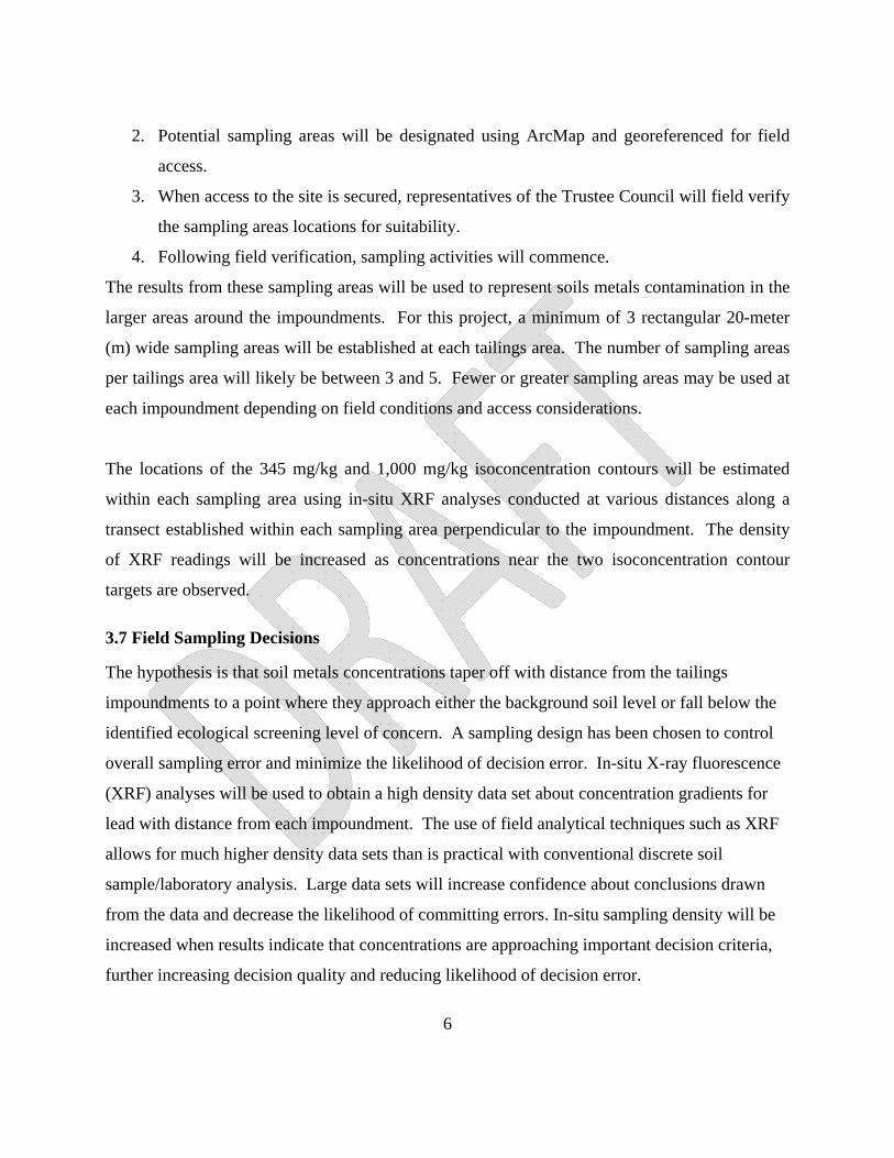
The results from these sampling areas will be used to represent soils metals contamination in the
larger areas around the impoundments. For this project, a minimum of 3 rectangular 20-meter
(m) wide sampling areas will be established at each tailings area. The number of sampling areas
per tailings area will likely be between 3 and 5. Fewer or greater sampling areas may be used at
each impoundment depending on field conditions and access considerations.
The locations of the 345 mg/kg and 1,000 mg/kg isoconcentration contours will be estimated
within each sampling area using in-situ XRF analyses conducted at various distances along a
transect established within each sampling area perpendicular to the impoundment. The density
of XRF readings will be increased as concentrations near the two isoconcentration contour
targets are observed.
3.7 Field Sampling Decisions
The hypothesis is that soil metals concentrations taper off with distance from the tailings
impoundments to a point where they approach either the background soil level or fall below the
identified ecological screening level of concern. A sampling design has been chosen to control
overall sampling error and minimize the likelihood of decision error. In-situ X-ray fluorescence
(XRF) analyses will be used to obtain a high density data set about concentration gradients for
lead with distance from each impoundment. The use of field analytical techniques such as XRF
allows for much higher density data sets than is practical with conventional discrete soil
sample/laboratory analysis. Large data sets will increase confidence about conclusions drawn
from the data and decrease the likelihood of committing errors. In-situ sampling density will be
increased when results indicate that concentrations are approaching important decision criteria,
further increasing decision quality and reducing likelihood of decision error.

7
Figure 2. The Anschutz site or Operable Unit 2 of the Madison County Mine Site.

8
4.0 Field Activities
Sampling will be conducted in one team of four personnel. In-situ XRF analysis for lead and
other metals will be performed along transects perpendicular to the impoundments at variable
distances in order to identify the distances at which the 345 mg/kg threshold is achieved.
Locational point data will be collected at each distance interval along each transect using a GPS
device. Confirmatory laboratory analyses will be conducted on a subset of 10% of collected
samples.
4.1 Soil Sampling
Except as otherwise noted, all aspects of sampling shall be performed using standard operating
procedures (SOPs) referenced in the QAPP (MDNR, 2011). Modifications to the sampling
methods in the SOPs are described below and other modifications may be made in the field
based upon conditions encountered. Any modifications to the methods will be noted on the field
sheets and in the Study Report.
4.1.1 In-Situ XRF Analysis
The XRF analyzer will be calibrated and standardized as per the manufacturer’s
recommendations. Known reference standards containing certified concentrations of lead, zinc,
and nickel at various levels will be analyzed prior to initiating field work as specified in the XRF
SOP (Appendix B). Rectangular 20-meter wide sampling areas will be established perpendicular
to the impoundment based on field observations, accessibility, landscape features, roadways, and
other practical considerations. A single transect will be established in the approximate center of
the sampling areas extending outward perpendicular to the impoundment. At each distance
interval any surface vegetation or duff layer will be removed. Any soil clinging to the vegetation
roots will be shaken back out over the bare soil. The soil will be flattened out, large debris
(rocks, sticks) removed, and a 30 second in-situ analysis will be performed. Distance intervals
from the starting point will be determined in the field by the Trustee Council representatives
based on site conditions and soils results reported by the XRFs. As soil metals concentrations
approach the ecological thresholds of 1,000 mg/kg Pb and 345 mg/kg Pb, the team will decrease
the distance intervals between in situ XRF readings to accurately determine surface soil

9
concentrations and isocontours. The tailings area, sampling area #, transect distance from
impoundment, and analyst name will be entered into the XRF prior to each analysis. Five
additional in-situ analyses will be conducted at the same distance interval perpendicular to the
transect at 5 foot spacings as shown in Figure 3.
The results will be recorded on the field sheet provided in Appendix C, and the averages for each
distance interval will be calculated. When average lead concentration along a transect drops
below the level of concern for lead (1000 mg/kg Pb or 345 mg/kg Pb), additional readings at
transect distances slightly closer to and further from the impoundment will be made in order to
better identify the distance at which to establish the isoconcentration contour.). Once the 345
mg/kg Pb in soil threshold is achieved by the sampling team, two more distance interval
samplings will be conducted in situ with the XRFs at 25 and 50 feet past the threshold location.
The additional sampling intervals will serve to increase confidence in the threshold location and
to assist in the construction of data analyses. The spacing of XRF readings along each transect
and the density of in-situ readings may be modified based on field conditions and access
considerations.

10
Figure 3. In-Situ XRF Analysis Within Sampling Areas.

11
4.2 Sample Conditioning and Analysis
Confirmatory soil samples will be returned to the laboratory, manually disaggregated and air
dried in aluminum pans lined with wax paper to an air dried soil moisture level that allows
samples to pass through sieves without clinging to sieve mesh. Throughout the drying process,
staff will periodically manually disaggregate clumps of soil to aid in drying and prevent the
formation of dense clumps of dried soil. The air dried samples will be returned to their original
bags, placed inside an additional bag, and then further disaggregated by striking the sample 30
times with a rubber mallet. The soil sample will then be passed through a 2mm sieve to obtain
the target particle size. The soil passing through the sieve will be placed inside a thin-walled re-
sealable plastic baggie or an 8 ounce glass jar. Sieves will be decontaminated between samples
by scrubbing with a nylon bristle brush and wiping with a damp paper towel. Samples will be
turned in to the laboratory at Environmental Services Program (ESP) for analyses.
4.3 Number of Samples, and Container and Preservation
The actual number of bagged soil samples to be collected will depend on observations made in
the field, but is anticipated to be approximately 30-40. At least one bagged sample will be
collected from each sampling area. XRF analysis will be conducted on the dried/sieved soil
samples following the XRF SOP in Appendix B. Of those, approximately 10%, or 4 samples
will be submitted to the laboratory for confirmatory analysis of lead, cadmium, copper, nickel,
and zinc following XRF analysis.
The soil and sediment samples will initially be collected in gallon size re-sealable plastic bags
for transport to the lab. Soil and sediment metal concentrations from mining are stable relative
to time frames measured in months. Time considerations at this scale should not have a
significant effect on results. Samples will therefore not be maintained on ice in the field or
refrigerated during sample conditioning or XRF analysis.
4.4 Chain-of-Custody
The confirmatory soil/sediment samples will be stored in the plastic bags in which they were
collected. Each bag will be labeled with the tailings area, sampling area #, date, time, and

12
collector initials using permanent marker. The samples will be recorded on the Soil Sample Log
Form shown in Appendix D. The samples will remain in the custody of MDNR personnel
during sample processing and analysis. Those samples identified for laboratory analysis will be
placed into appropriate sample containers and entered onto a chain of custody form to be
relinquished to a sample custodian at the MDNR/ESP laboratory for analysis.
5.0 Quality Control
5.1 Field Decontamination
Clean disposable latex gloves will be worn by sampling personnel and clean or field
decontaminated equipment will be utilized for each separate site to minimize the possibility of
cross-contamination. Reusable soil sampling equipment will be cleaned between samples as
follows:
Scraping with putty knife or similar tool to remove soil clumps;
Brushing with stiff-bristle nylon brush to remove visible soil debris;
Cleaning with soapy water and further brushing;
Rinsing tool with deionized (DI) water;
Wiping dry with clean paper towels
5.2 Quality Assurance/Quality Control (QA/QC) Samples
The following samples will be collected as part of the quality control/quality assurance
procedures for the investigation.
5.2.1 Equipment Rinsate Blank
An equipment rinsate blank will be collected after decontaminating the soil/sediment tools
between samples once per day of sampling. Following decontamination of the tool, the stainless
steel scoops will be rinsed with DI water into a sample container which will travel with the other
samples back to the laboratory for analysis.

13
5.2.2 XRF Precision Samples
The precision of bagged sample XRF analyses will be evaluated by conducting multiple analyses
of selected samples at a frequency of 5% for bagged sample analysis and once per day per
analyzer for in-situ analysis. Samples will be chosen to reflect the full range of concentrations
observed, however, special emphasis will be placed on selecting samples near the screening
levels if possible. The selected sample will be analyzed seven separate times without moving the
bagged sample (without moving the analyzer for in-situ analysis) between each analysis. The
relative standard deviation among the multiple analyses will be assessed as an indication of
instrument precision.
The precision of in-situ XRF analyses will be evaluated by conducting multiple analyses at
selected locations at a frequency of once per day per instrument. At the selected location, the
analyzer will be place on the soil surface, and seven consecutive 30-second XRF analyses will be
conducted without moving the analyzer between tests. The relative standard deviation among
the multiple analyses will be assessed as an indication of instrument precision.
5.2.3 Laboratory QC
Laboratory precision and accuracy will be assessed as described in the Quality Assurance Project
Plan (QAPP) for Natural Resource Damages, Revision 3, April, 2011.
6.0 Investigation Derived Wastes (IDW) Plan
Efforts will be made to minimize IDW generation. IDW may include soil, sediment,
decontamination fluids, disposable sampling equipment, and disposable personal protective
equipment (PPE).
Field personnel will attempt to return unused soils to their source immediately after generation
or, if warranted, containerize and return to the ESP laboratory for proper disposal. Disposable
PPE and disposable sampling equipment will generally be handled as solid waste, containerized,
and properly disposed. Wash and rinse waters generated during equipment decontamination will

14
generally be discharged to the ground on-site or, if warranted, containerized and returned to the
ESP laboratory for proper disposal.
7.0 Site Safety
A safety briefing will be held on-site prior to initiating field activities and field personnel will be
required to read and sign the site-specific health and safety plan. The site safety plan is attached
as Appendix A.
8.0 Reporting
MDNR will provide a copy of the chain of custodies and laboratory result sheets for laboratory
confirmation samples. MDNR and USFWS will prepare sampling documentation, including
sample results for use by the Trustees.

15
REFERENCES
Beyer, W.N., J.C. Franson, J.B. French, T. May, B.A. Rattner, V.I. Shearn-Bochsler, S.E. Warner, J. Weber, and D. Mosby. 2013. Toxic exposure of songbirds to lead in the Southeast Missouri Lead Mining District. Arch. Environ. Contam. Toxicol. 65(3):598-610.
Stratus Consulting. 2014. Associating Soil Lead with Adverse Effects on Songbirds in the Southeast Missouri Mining District July 28, 2014.
U.S. Geological Survey. 2016. Geochemistry of soils from the PLUTO database. Accessed at: http://mrdata.usgs.gov/pluto/soil/select.php?place=f29123&div=fips on 2/24/2016.

16
SIGNATURES
Prepared by: _________________________
Eric Gramlich
Natural Resource Damages Assessment and Restoration
Manager
Hazardous Waste Program
Missouri Department of Natural Resources
_________________________
John Weber
U.S. Fish and Wildlife Service
Columbia Missouri Field Station
Date: __________________________

APPENDIX A
Health & Safety Plan

MISSOURI DEPARTMENT OF NATURAL RESOURCES
DIVISION OF ENVIRONMENTAL QUALITY
ENVIRONMENTAL SERVICES PROGRAM
SITE HEALTH AND SAFETY PLAN
1.0 INTRODUCTION
This plan has been prepared for implementation by DNR employees, using operating procedures for which they are
specifically trained. Any use of the plan by other agencies, organizations, or private individuals is at their own risk.
2.0 KEY PERSONNEL
MDNR OSC: Eric Gramlich SAFETY OFFICER: Eric Gramlich
OTHER PERSONNEL/TITLE:
Kathy Rangen, Environmental Specialist
John Nichols, Environmental Specialist
3.0 SITE INFORMATION
Site name Madison County Mine Site/Anschutz Site
Counties/Cities: Madison County, Fredericktown
Sampling date: Winter 2016
Site Description: Historical mining activities impacting stream sediments/soils/surface waters .
3.1 Overall Incident Risk/Hazard Analysis
Chemical: Serious Moderate XX Low Unknown
Physical: Serious Moderate XX Low Unknown
3.2 Contaminant(s) of Concern: Lead (Pb), Cadmium (Cd), Copper (Cu), Nickel (Ni), Zinc (Zn), and
Arsenic (As) Cobalt (Co).
3.2.1 Physical State: XX Liquid XX Solid Sludge Gas/Vapor

Chemical Characteristics: (check all that apply)
a. carcinogen b. biological c. corrosive d. combustible
e. explosive f. flammable g. volatile XX h. poison
i. radioactive j. reactive k. other:
Physical Hazards: (check all that apply)
a. XX drowning b. below grade c. confined space* d. noise
e. XX splash f. fire/burn g. puncture h. heat stress
i. xx cut XX j. slip/trip/fall xx k. cold stress l. electrical
m. mechanical/heavy equipment XX n. other: animals, insects, plants.
* The need for confined space entry by ESP personnel shall be evaluated on a site-by-site basis. A confined
space entry permit must be signed by the appropriate Unit or Section Chief prior to ESP employees
entering a confined space (29 CFR 1910.146). Confined space entry shall be screened in at least Level B
prior to downgrade. Adequate resources must be available and specific planning and tasks
determined before confined space entry is initiated.
3.3 Task-Specific Risk Analysis (attach additional sheets as necessary)
Task Description
Chemical Hazards
Physical Hazards
Level of
Protection
Sample Collection
h
e, h, j, n
D
4.0 MEDICAL SURVEILLANCE AND PERSONNEL TRAINING REQUIREMENTS
All ESP field personnel participate in a medical monitoring program and are trained at least to the level of
"Hazardous Substance Emergency Response-Technician" as required and specified in the department's written
health and safety program located in Section 2 of the MDNR-Hazardous Substances Emergency Response Plan

(HSERP). The written policy satisfies requirements set out in 29 CFR 1910.120. MDNR ESP's respiratory
protection program meets the requirements of 29 CFR 1910.134.
ESP personnel will ascertain as much information as possible regarding health and safety issues associated with the
site prior to initial entry. Information shall include chemical and physical hazards as listed above, types and
amounts of materials involved, and citizens/areas threatened by the incident.
5.0 PERSONAL PROTECTIVE EQUIPMENT
ESP shall utilize the Protection Level categories defined in 29 CFR 1910.120, Appendix B, and known as Levels A,
B, C, and D. Refer to Section 2 of the MDNR-HSERP for definitions of Protection Levels. ESP personnel shall
inspect APRs and SCBAs at least monthly and maintain a record of such to ensure equipment is functional.
Levels of protection shall be reassessed and upgraded as conditions change and information is updated to comply
with worker safety while performing site activities.
Action Levels for evacuation of work zone pending reassessment of conditions:
Level D: O2 < 19.5% or > 25%; explosive atmosphere > 10% LEL; organic vapors > background levels; other .
Level C: O2 < 19.5% or > 25%; explosive atmosphere > 20% LEL; organic vapors (in breathing zone) > 5 m.u.;
other .
Level B: O2 Explosive atmosphere > 20% LEL; unknown organic vapors (in breathing zone) > 500 m.u.; other .
Level A: ESP personnel shall evaluate the need for entry on a site-specific basis and may utilize its emergency
response contractor for Level A situations which may arise.
6.0 FREQUENCY AND TYPE OF AIR MONITORING/SAMPLING
Instrument
Contaminant of Concern
Sample Location
(Area/Source)
Frequency
Odor Threshold/
Description
NA

7.0 SITE CONTROL MEASURES
7.1 The "Buddy-System": ESP personnel performing any work activities within the exclusion zone shall employ
the "buddy-system" at all times, as required and defined in Section 2 of the MDNR-HSERP. The "buddy-system"
may not be required while an ESP staff member is observing or providing oversight of cleanup activities performed
by a contractor or responsible party.
7.2 Safe work Practices: Refer to Section 2 of the MDNR-HSERP for written safety practices to be followed at all
times by ESP personnel while on-site at an incident.
7.3 Site Communications: The use of two-way radios or establishment of hand signals for communications shall be
determined prior to entering the work zone and followed by ESP personnel.
7.4 Radiation Safety: Due to the possibility of an unknown radiation hazard being present on a site, ESP personnel
shall be required to wear radiation indicator badges (TLD badges) while on-site.
7.5 Work Zones: ESP personnel shall ensure work zones are established and be aware of their locations.
8.0 DECONTAMINATION PROCEDURE/SOLUTIONS:
Personnel: Gloves and clothing will be placed in a garbage bag and returned to Jefferson City for proper
disposal.
Equipment: Returned to Jefferson City for proper decontamination.
Instruments: Returned to Jefferson City for proper decontamination or disposal.
Decontamination fluids/materials may be containerized for proper disposal.
9.0 EMERGENCY INFORMATION:
In the event of an emergency, notify the MDNR Environmental Emergency Response Office
at 573/634-2436. The Duty Officer will make the appropriate notifications.

10.0 ADDITIONAL EMERGENCY INFORMATION/NUMBERS:
Hospital: Madison Medical Center ---611 W. Main, Fredericktown, MO 63640 Phone: (573) 783-1096 /
Location/Specific directions from Site: See Map directions.
Name/Location Telephone Number
Ambulance: Madison County Ambulance Phone: (573) 783-7900
Police/Sheriff: 911
Fire:
Poison Control:
Cellular Telephones/Other:
1) Central Accident Reporting Office- WORK RELATED INJURY 1-800-624-2354
This number is to be called in the event of a NON LIFE THREATENING injury PRIOR to seeking medical care.
11.0 SIGNATURES
ESP personnel shall certify they have read the plan and addressed any questions regarding worker health and safety by
signing and dating below followed by printing their name and title.
Signature Printed Name/Title Date TLD Badge

611 W. Main Fredericktown, MO 63645

APPENDIX B
XRF Standard Operating Procedures

Standard Operating Procedure for XRF Analyzers
MCMS Transition Zone Study
In-situ surface soil analyses will be conducted in the field along transects established
perpendicular to the impoundments. Bagged soil samples will be analyzed with the analyzer in the
testing stand and controlled from a laptop PC. A 30-second analysis time will be used for in-situ
testing and 45 second analysis time for all bagged samples. Note, do not operate the laptop PC
software with the laptop connected to the network servers.
All XRF analyses will be recorded either on field sheets or in a written log book for each instrument. The analyst will record the date, the XRF run number (automatically generated by the XRF), sample ID information, and the total Pb result in mg/kg.
I. Startup
Power up the analyzer and start the InnovX PC software. The instrument will automatically perform an initialization procedure, which lasts for 1-2
minutes. Following initialization, place the stainless steel standardization disc over the instrument’s
sampling window in the test stand and close the stand cover. Click the “Standardize” button from the upper left window titled “Soil” in the PC software.
The instrument will perform an internal 60-second standardization procedure. During standardization, and any other time the x-ray tube is on, the red light on top of the test stand will flash. When the x-ray tube is off, the red light will remain on solid. Do not open the test stand lid when the light is flashing.
Following standardization, an information window will pop up displaying the analyzer resolution. Record the resolution in the XRF Log Book along with the Run number automatically assigned by the analyzer.
The analyzer is now ready to analyze standard reference materials (SRMs).
II. Calibration Check
The NIST 5861 (41ppm Pb), 4315 (244ppm), 2586 (431ppm), 2711 (1162), and 2710 (5532ppm), and Blank SRMs will be analyzed at the beginning of each use. Selected SRMs will also be reanalyzed periodically during the day based on site findings and length of time in the field.

On the PC software main menu bar, select “Edit” and then chose “Edit Test Information”. A data entry window will pop up allowing input of information about the next test.
Select your name from the “Analyst” dropdown menu & select the check sample from the “Chk_Sampl” dropdown list.
Click the “Start” button in the Soil Window in the upper left corner of the screen to initiate the test.
Assess instrument calibration by comparing the measured values to the control chart prepared for each analyzer for each SRM. Verify that the result is within 2SD of the control chart mean, if so, continue to In-situ or Bagged Sample Analysis sections below.
If values outside 2SD of control chart mean are observed, re-analyze the calibration check sample, or if there are more than one SRM sample cup, analyze another one. If the measured value is still outside 2SD, re-standardize as described above, and re-analyze the standard(s). If the result is still outside 2SD, note the failure in the logbook. If more than one check sample fails this procedure on a given day (particularly if the exceedances are in the same direction – e.g. both 2SD above or below the mean), it may be necessary to update the control charts, manually enter new calibration response factors into the analyzers, or both.
III. Sample Analysis
All XRF analyses will be conducted using InnovX X-ray tube analyzers. In the event of instrument malfunction in the field, in-situ analyses may also be conducted using Niton Xli700 Amerecium232 isotope analyzers.
In-Situ Analysis
Following successful calibration check, click Edit from the main menu bar and select Edit sample Information.
Enter all applicable information about the first in-situ analysis into the iPAQ using the dropdown and direct edit fields.
Remove any vegetation from the soil surface exposing an area of approximately five square inches. Shake out any soil clinging to vegetation roots back onto the cleared spot and use a stainless steel spoon or other tool to prepare a one square inch area on which to place the XRF analyzer window. Place a thin-walled plastic baggie over the analyzer snout to protect it from the soil.
Initiate a 30 second analysis. The analyzer can be operated hands-free using the tripod attachment.
Record the information in columns on the XRF Data Field Sheet, and continue with additional analyses.
When data from a given distance for a transect is collected, calculate and record the average on the field sheet.

Periodically and at the end of the day, re-analyze the SRMs as described in the Calibration Check section above.
Once per day per analyzer, conduct a precision check by repeating an in-situ analysis 7 times without moving the analyzer between tests. The precision check should be conducted in an area found to contain elevated lead, preferably a concentration near an action/screening level.
Bagged Sample Analysis (InnovX analyzers)
Following successful calibration check, click Edit from the main menu bar and select Edit Sample Information.
Enter all applicable information about the first sample to be analyzed from the bag label, using the dropdown menus and direct edit fields
Gently roll the sieved soil around inside the bag to homogenize; Place the sample over the analyzer’s sampling window ensuring that the soil and bag are in
as close contact with the window as possible. Close the stand cover. Click the Start button from the Soil window to initiate the test. The data being acquired will appear in the Chemistry window in the lower center of the PC
screen during analysis. After analysis, the results will appear in the Results window on the PC. A running list of the analyses will appear in the window at the lower left of the PC screen. The sample information will remain from the previous test, so no changes are necessary for
subsequent replicate analyses on a given sample bag. Roll the sieved soil around inside the bag, and re-analyze. Repeat analysis 2 more times. Calculate a mean and 95%UCL for the replicate analyses.
After completing replicate analysis on a bagged sample, click the Edit Sample Information again and enter information for the next bagged sample as above.
Place the second sample in the test stand, close the cover and initiate the analysis.
If the mean and the 95% UCL lead concentrations straddle a screening level, conduct 3 additional replicate analyses, recalculate the mean and UCL and reassess. This process may need to be repeated for another round of 3 analyses in an effort to get both the mean and UCL on one side of the screening level. It may not be possible in all cases to do this (e.g. when the mean and UCL are very close to the screening level). If after 10 replicate analyses, the mean and UCL still straddle the screening level, the sample will be considered to contain lead above the screening level

Repeat for remaining samples An instrument precision check will be conducted at a frequency of 5%. This will consist of
analyzing a sample seven separate times without moving the sample in between each analysis. The %RSD on the replicate analyses should not exceed 15%. Select a bagged sample for the precision check that has elevated lead levels, preferably a concentration near a screening/action level if possible.
IV. Data Downloading
After the last analysis for the day, select Readings from the main menu bar, and chose Export Readings.
In the Export pop up box, verify that the “Export readings on date” radio button is selected, the Mode to export is “All”, and today’s date is circled on the calendar.
Click OK. Insert a USB thumb drive in the laptop, download data to it, and then move data onto
network server. Select the directory and file name for the downloaded data. For this project, file naming convention is date & XRF serial number (e.g. 10_14_11_5434)
Verify that the file type is “Comma Separated Values”, and click Save. A message will pop up indicating a successful download, and asking whether you would
like to open the file. Select Yes, and file will open in Excel. Verify that the data appears correct. Make any corrections you had noted in the run log book.
Choose Save As from the File menu, and select File Type “Microsoft Excel 97 Workbook. Close the InnovX software, power down the analyzer, and shut down the laptop PC. Copy the file from thumb drive to the network as soon as possible after analyses. Files will
be stored in the H:/Sections/Superfund/SiteFiles/MCMS Transition Zone/XRF directory.
Note: For any operation that requests a password, the administrator password is lower case z, and
the factory password is 1234.

APPENDIX C
Sampling Area Field Sheet


APPENDIX D
Soil Sample Log Form