Embed Size (px)
Citation preview

1
DRAFT IN WIDE
CIRCULATION
DOCUMENT DESPATCH ADVICE
REF: DATE
Doc:PCD 1(11382 )C 23.02.2017
Technical Committee: Methods of tests for Petroleum, Lubricants and Related
Products Sectional Committee, PCD 1
All members of
i) Interested members of PCDC
ii) Methods of tests for Petroleum, Lubricants and Related Products Sectional
Committee, PCD 1
iii) All subcommittees of PCD 1
iv) All others interested.
Dear Sir,
Please find enclosed the following document:
Doc: No. Title
PCD 1(11382 )C Methods of Test for Petroleum and its Products [P: 142]
Determination of water separation characteristics of aviation turbine fuels by portable separometer (First
Revision of IS 1448[P: 142])
Kindly examine this draft and forward your views stating any difficulty which you are
likely to experience in your business or profession, if this is finally adopted as an Indian
standard.
Last date for comments is : 25 March 2017
Comments if any, may please be made in the format as given overleaf and mailed to the
undersigned at the above address.
The document is also hosted on BIS website www.bis.org.in.
Thanking you,
Signature :
Name : A.K. Bhatnagar
Designation : Sc.F & Head (PCD)
Email: [email protected]; [email protected]
2
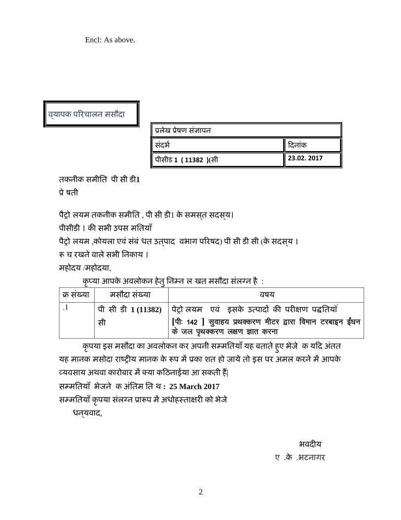
Encl: As above.
तकनीक समीतत पी सी डी1
प्रेषिती
पैट्रोलियम तकनीक समीतत , पी सी डी1 के समसत् सदसय्।
पीसीडी 1 की सभी उपसलमततय ाँ पैट्रोलियम ,कोयि एवं संबंधित उतप् द षवभ ग परििद ( पी सी डी सी )के सदसय् ।
रूधि िखने व िे सभी तनक य ।
महोदय /महोदय , कृप्य आपके अविोकन हेतु तनम्नलिखखत मसौद संिग्न है :
क्र संख्य मसौद संख्य षविय
1. पी सी डी 1 (11382)
सी
पेट्रोलियम एवं इसके उत् प दक की पि्षण प पधतिततय ं
[ih% 142 ] lqokg; izFkDdj.k ehVj }kjk foeku Vjckbu bZa/ku
ds ty i`FkDdj.k y{k.k Kkr djuk
कृपय इस मसौद क अविोकन कि अपनी सम्मततय ाँ यह बत ते हुए भेजे कक यदद अतंत
यह म नक मसोद ि ष्ट्ट्र्य म नक के रूप में प्रक लित हो ज ये तो इस पि अमि किने में आपके
व्यवस य अथव क िोब ि में क्य कदिन ईय आ सकती हैं| सम्मततय ाँ भेजने कक अतंतम ततधथ : 25 March 2017
सम्मततय ाँ कृपय संिग्न प्र रूप में अिोहस्त षण ि् को भेजे
िनय्व द,
भवद्य
ए .के .भटन गि
वय् पक परिि िन मसौद प्रिेख पे्रिप सजं्ञ पन
सदंभभ ददन ंक
पीसीड 1 ( 11382 ))सी 23.02. 2017
3
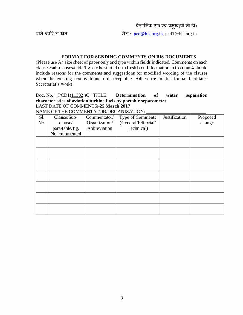
वैज्ञ तनक एफ एवं प्रमुख(पी सी डी)
प्रतत उपरिलिखखत मेि : [email protected], [email protected]
FORMAT FOR SENDING COMMENTS ON BIS DOCUMENTS
(Please use A4 size sheet of paper only and type within fields indicated. Comments on each
clauses/sub-clauses/table/fig. etc be started on a fresh box. Information in Column 4 should
include reasons for the comments and suggestions for modified wording of the clauses
when the existing text is found not acceptable. Adherence to this format facilitates
Secretariat’s work)
Doc. No.: _PCD1(11382 )C TITLE: Determination of water separation
characteristics of aviation turbine fuels by portable separometer LAST DATE OF COMMENTS: 25 March 2017
NAME OF THE COMMENTATOR/ORGANIZATION: _________________________
Sl.
No.
Clause/Sub-
clause/
para/table/fig.
No. commented
Commentator/
Organization/
Abbreviation
Type of Comments
(General/Editorial/
Technical)
Justification Proposed
change
4
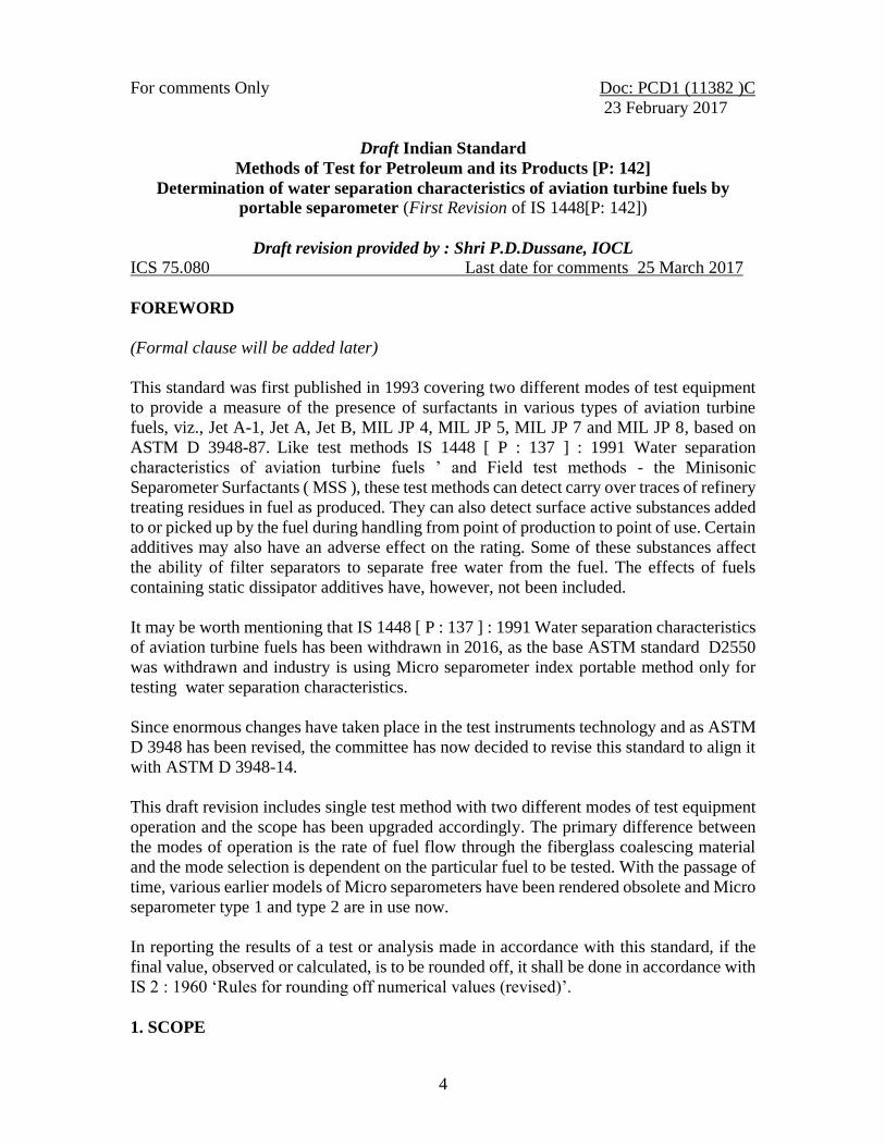
For comments Only Doc: PCD1 (11382 )C
23 February 2017
Draft Indian Standard
Methods of Test for Petroleum and its Products [P: 142]
Determination of water separation characteristics of aviation turbine fuels by
portable separometer (First Revision of IS 1448[P: 142])
Draft revision provided by : Shri P.D.Dussane, IOCL
ICS 75.080 Last date for comments 25 March 2017
FOREWORD
(Formal clause will be added later)
This standard was first published in 1993 covering two different modes of test equipment
to provide a measure of the presence of surfactants in various types of aviation turbine
fuels, viz., Jet A-1, Jet A, Jet B, MIL JP 4, MIL JP 5, MIL JP 7 and MIL JP 8, based on
ASTM D 3948-87. Like test methods IS 1448 [ P : 137 ] : 1991 Water separation
characteristics of aviation turbine fuels ’ and Field test methods - the Minisonic
Separometer Surfactants ( MSS ), these test methods can detect carry over traces of refinery
treating residues in fuel as produced. They can also detect surface active substances added
to or picked up by the fuel during handling from point of production to point of use. Certain
additives may also have an adverse effect on the rating. Some of these substances affect
the ability of filter separators to separate free water from the fuel. The effects of fuels
containing static dissipator additives have, however, not been included.
It may be worth mentioning that IS 1448 [ P : 137 ] : 1991 Water separation characteristics
of aviation turbine fuels has been withdrawn in 2016, as the base ASTM standard D2550
was withdrawn and industry is using Micro separometer index portable method only for
testing water separation characteristics.
Since enormous changes have taken place in the test instruments technology and as ASTM
D 3948 has been revised, the committee has now decided to revise this standard to align it
with ASTM D 3948-14.
This draft revision includes single test method with two different modes of test equipment
operation and the scope has been upgraded accordingly. The primary difference between
the modes of operation is the rate of fuel flow through the fiberglass coalescing material
and the mode selection is dependent on the particular fuel to be tested. With the passage of
time, various earlier models of Micro separometers have been rendered obsolete and Micro
separometer type 1 and type 2 are in use now.
In reporting the results of a test or analysis made in accordance with this standard, if the
final value, observed or calculated, is to be rounded off, it shall be done in accordance with
IS 2 : 1960 ‘Rules for rounding off numerical values (revised)’.
1. SCOPE
5
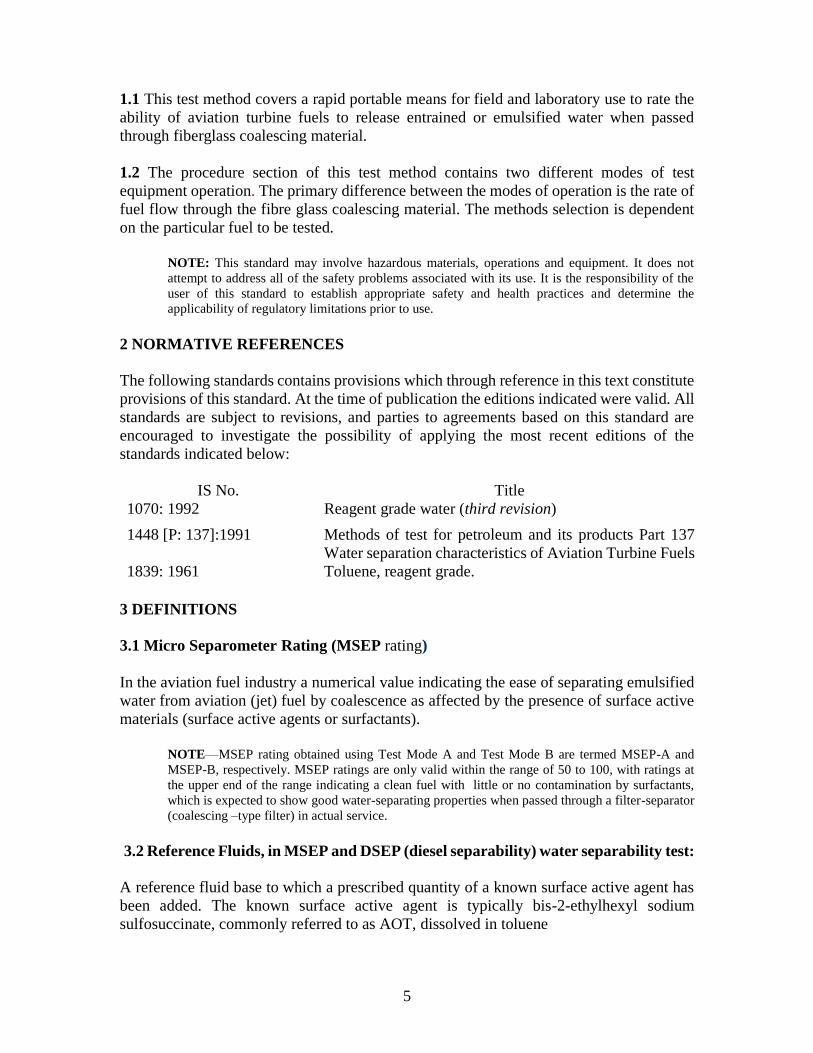
1.1 This test method covers a rapid portable means for field and laboratory use to rate the
ability of aviation turbine fuels to release entrained or emulsified water when passed
through fiberglass coalescing material.
1.2 The procedure section of this test method contains two different modes of test
equipment operation. The primary difference between the modes of operation is the rate of
fuel flow through the fibre glass coalescing material. The methods selection is dependent
on the particular fuel to be tested.
NOTE: This standard may involve hazardous materials, operations and equipment. It does not
attempt to address all of the safety problems associated with its use. It is the responsibility of the
user of this standard to establish appropriate safety and health practices and determine the
applicability of regulatory limitations prior to use.
2 NORMATIVE REFERENCES
The following standards contains provisions which through reference in this text constitute
provisions of this standard. At the time of publication the editions indicated were valid. All
standards are subject to revisions, and parties to agreements based on this standard are
encouraged to investigate the possibility of applying the most recent editions of the
standards indicated below:
3 DEFINITIONS
3.1 Micro Separometer Rating (MSEP rating)
In the aviation fuel industry a numerical value indicating the ease of separating emulsified
water from aviation (jet) fuel by coalescence as affected by the presence of surface active
materials (surface active agents or surfactants).
NOTE—MSEP rating obtained using Test Mode A and Test Mode B are termed MSEP-A and
MSEP-B, respectively. MSEP ratings are only valid within the range of 50 to 100, with ratings at
the upper end of the range indicating a clean fuel with little or no contamination by surfactants,
which is expected to show good water-separating properties when passed through a filter-separator
(coalescing –type filter) in actual service.
3.2 Reference Fluids, in MSEP and DSEP (diesel separability) water separability test:
A reference fluid base to which a prescribed quantity of a known surface active agent has
been added. The known surface active agent is typically bis-2-ethylhexyl sodium
sulfosuccinate, commonly referred to as AOT, dissolved in toluene
IS No. Title
1070: 1992 Reagent grade water (third revision)
1448 [P: 137]:1991 Methods of test for petroleum and its products Part 137
Water separation characteristics of Aviation Turbine Fuels
1839: 1961 Toluene, reagent grade.
6
3.3 Surfactant:
In petroleum fuels, surface active material (or surface active agent) that could disarm
(deactivate) filter separator (coalescing) elements so that free water is not removed from
the fuel in actual service.
NOTE— Technically, surfactants affect the interfacial tension between water and fuel which affects
the tendency of water to coalesce into droplets.
3.4 Reference Fluid Base
In aviation MSEP water separability tests, jet fuel that has been cleaned in a prescribed
manner to remove all surface-active contaminants (agents), and having a minimum MSEP
rating of 97.
4. SUMMARY OF TEST METHOD
This test method uses a Micro separometer to perform the test. A water /fuel sample
emulsion is created in syringe using a high-speed mixer. The emulsion is then expelled
from the syringe at a programmed rate through standard fiberglass coalescer and the
effluent is analyzed for uncoalesced water by a light transmission measurement. The results
are reported on a 0 to 100 scale to the nearest whole number. High ratings indicate the
water is easily coalesced implying that the fuel is relatively free of surfactant materials. A
test can be performed in 5 to 10 min.
5 SIGNIFICANCE AND USE
5.1 This test method provides a measure of the presence of surfactants in aviation turbine
fuels. Like Field Test Methods, this test method can detect carry over traces of refinery
treating residues in fuel as produced. This can also detect surface active substances added
to or picked up by the fuel during handling from point of production to point of use. Certain
additives can also have an adverse effect on the rating. Some of these substances affect the
ability of filter separators to separate free water from the fuel.
NOTE—The effects of fuels containing static dissipater additives have not been investigated but
test programs using these additives are under review.
5.2 The Micro separometer has a measurement range from 50 to 100. Values obtained
outside of those limits are undefined and invalid. In the event a value greater than 100 is
obtained, there is a good probability that the light transmittance was reduced by material
contained in the fuel used to set the 100 reference level. The material was subsequently
removed during the coalescing portion of the test, thus, the processed fuel had a higher
light transmittance than the fuel sample used to obtain the 100 reference level resulting in
the final rating measuring in excess of 100.
5.3 The Test Mode B option is used to determine water separation ratings for MIL JP-4 fuels containing fuel system corrosion and icing inhibitors.
7
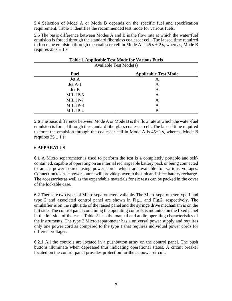
5.4 Selection of Mode A or Mode B depends on the specific fuel and specification
requirement. Table 1 identifies the recommended test mode for various fuels.
5.5 The basic difference between Modes A and B is the flow rate at which the water/fuel emulsion is forced through the standard fiberglass coalescer cell. The lapsed time required to force the emulsion through the coalescer cell in Mode A is 45 s ± 2 s, whereas, Mode B requires 25 s ± 1 s.
Table 1 Applicable Test Mode for Various Fuels
Available Test Mode(s)
Fuel Applicable Test Mode
Jet A A
Jet A-1 A
Jet B A
MIL JP-5 A
MIL JP-7 A
MIL JP-8 A
MIL JP-4 B
5.6 The basic difference between Mode A or Mode B is the flow rate at which the water/fuel
emulsion is forced through the standard fiberglass coalescer cell. The lapsed time required
to force the emulsion through the coalescer cell in Mode A is 45±2 s, whereas Mode B
requires 25 ± 1 s.
6 APPARATUS
6.1 A Micro separometer is used to perform the test is a completely portable and self-
contained, capable of operating on an internal rechargeable battery pack or being connected
to an ac power source using power cords which are available for various voltages.
Connection to an ac power source will provide power to the unit and effect battery recharge.
The accessories as well as the expendable materials for six tests can be packed in the cover
of the lockable case.
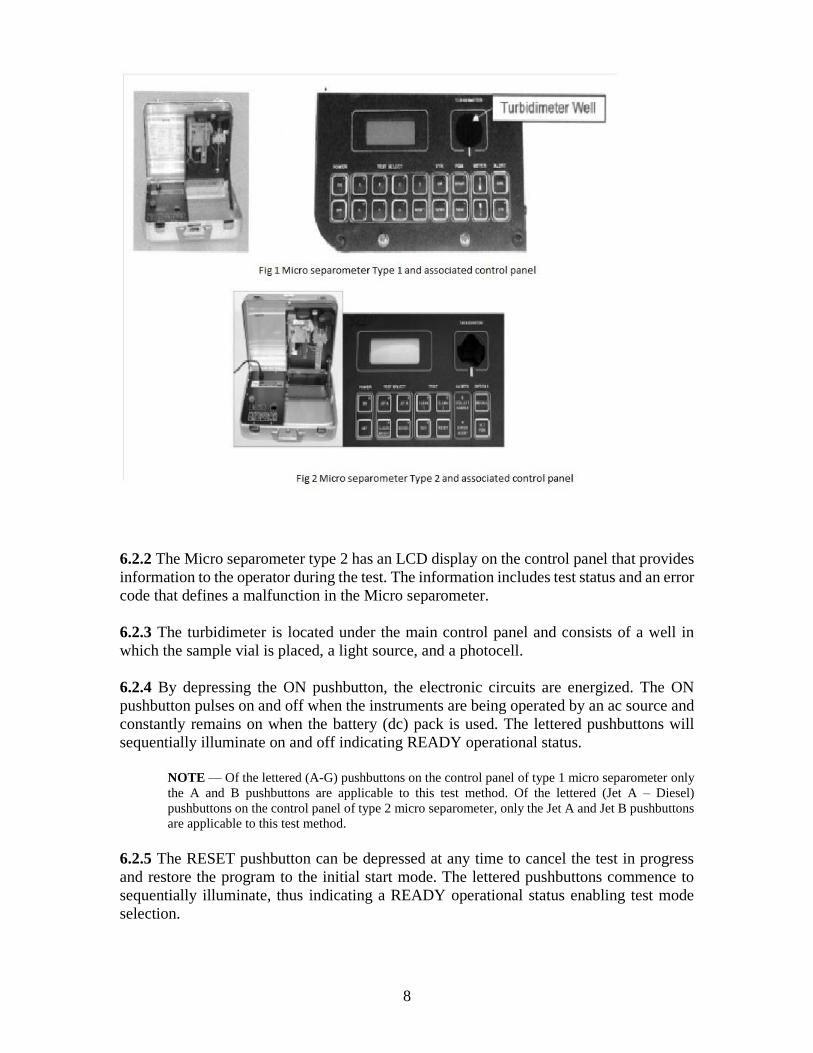
6.2 There are two types of Micro separometer available. The Micro separometer type 1 and
type 2 and associated control panel are shown in Fig.1 and Fig.2, respectively. The
emulsifier is on the right side of the raised panel and the syringe drive mechanism is on the
left side. The control panel containing the operating controls is mounted on the fixed panel
in the left side of the case. Table 2 lists the manual and audio operating characteristics of
the instruments. The type 2 Micro separometer has a universal power supply and requires
only one power cord as compared to the type 1 that requires individual power cords for
different voltages.
6.2.1 All the controls are located in a pushbutton array on the control panel. The push
buttons illuminate when depressed thus indicating operational status. A circuit breaker
located on the control panel provides protection for the ac power circuit.
8
6.2.2 The Micro separometer type 2 has an LCD display on the control panel that provides
information to the operator during the test. The information includes test status and an error
code that defines a malfunction in the Micro separometer.
6.2.3 The turbidimeter is located under the main control panel and consists of a well in
which the sample vial is placed, a light source, and a photocell.
6.2.4 By depressing the ON pushbutton, the electronic circuits are energized. The ON
pushbutton pulses on and off when the instruments are being operated by an ac source and
constantly remains on when the battery (dc) pack is used. The lettered pushbuttons will
sequentially illuminate on and off indicating READY operational status.
NOTE — Of the lettered (A-G) pushbuttons on the control panel of type 1 micro separometer only
the A and B pushbuttons are applicable to this test method. Of the lettered (Jet A – Diesel)
pushbuttons on the control panel of type 2 micro separometer, only the Jet A and Jet B pushbuttons
are applicable to this test method.
6.2.5 The RESET pushbutton can be depressed at any time to cancel the test in progress
and restore the program to the initial start mode. The lettered pushbuttons commence to
sequentially illuminate, thus indicating a READY operational status enabling test mode
selection.
9
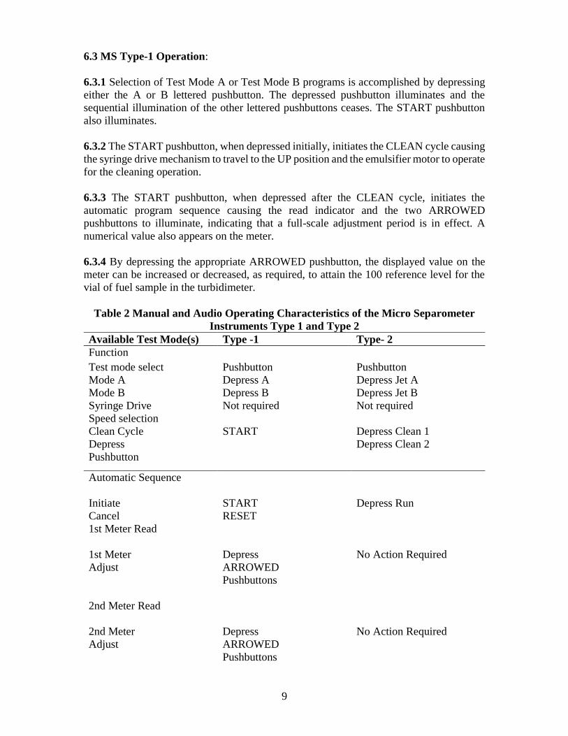
6.3 MS Type-1 Operation:
6.3.1 Selection of Test Mode A or Test Mode B programs is accomplished by depressing
either the A or B lettered pushbutton. The depressed pushbutton illuminates and the
sequential illumination of the other lettered pushbuttons ceases. The START pushbutton
also illuminates.
6.3.2 The START pushbutton, when depressed initially, initiates the CLEAN cycle causing
the syringe drive mechanism to travel to the UP position and the emulsifier motor to operate
for the cleaning operation.
6.3.3 The START pushbutton, when depressed after the CLEAN cycle, initiates the
automatic program sequence causing the read indicator and the two ARROWED
pushbuttons to illuminate, indicating that a full-scale adjustment period is in effect. A
numerical value also appears on the meter.
6.3.4 By depressing the appropriate ARROWED pushbutton, the displayed value on the
meter can be increased or decreased, as required, to attain the 100 reference level for the
vial of fuel sample in the turbidimeter.
Table 2 Manual and Audio Operating Characteristics of the Micro Separometer
Instruments Type 1 and Type 2
Available Test Mode(s) Type -1 Type- 2
Function
Test mode select Pushbutton Pushbutton
Mode A Depress A Depress Jet A
Mode B Depress B Depress Jet B
Syringe Drive Not required Not required
Speed selection
Clean Cycle START Depress Clean 1
Depress Depress Clean 2
Pushbutton
Automatic Sequence
Initiate START Depress Run
Cancel RESET
1st Meter Read
1st Meter Depress No Action Required
Adjust ARROWED
Pushbuttons
2nd Meter Read
2nd Meter Depress No Action Required
Adjust ARROWED
Pushbuttons
10
Collect Sample Short Tone and C/S Short Tone and C/S
Annunciator Lamp Annunciator Lamp
Illuminates Illuminates
3rd Meter Read
Record Pulsed Tone Sounds 5 s Steady Tone
Measurement into 3rd Meter Read
6.4 MS Type – 2 Operation
6.4.1 Selection of Test Mode A or Test Mode B program is accomplished by depressing
either the Jet A or Jet B lettered pushbutton. The depressed pushbutton illuminates and the
sequential illumination of the other lettered pushbuttons ceases. The CLEAN 1 pushbutton
also illuminates.
6.4.2 The first and second clean cycles are initiated by depressing the CLEAN 1 and
CLEAN 2 pushbuttons. The RUN pushbutton will illuminate at the end of the second clean
cycle.
6.4.3 The automatic portion of the test sequence is initiated by depressing the RUN
pushbutton.
6.4.4 The 100 reference level for the vial of fuel in the turbidimeter is set automatically
and does not require any adjustment. If the turbidimeter could not auto adjust to 100, the
error alert indicator illuminates and an ERR-04 is displayed.
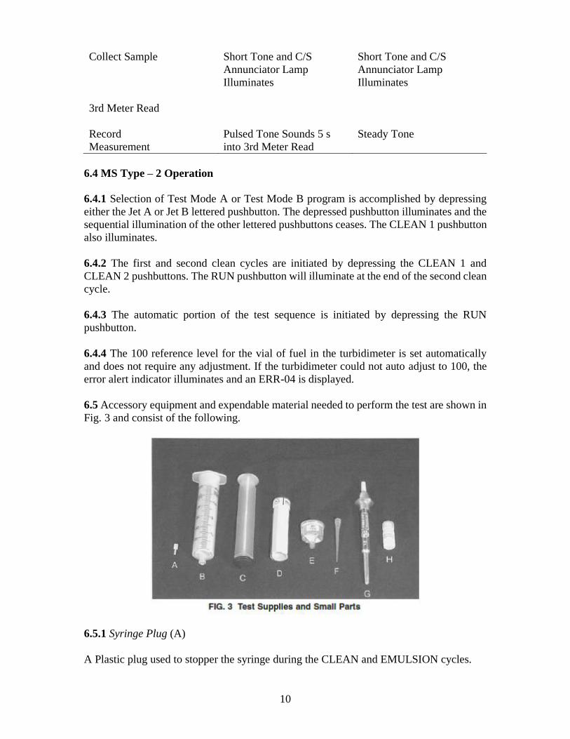
6.5 Accessory equipment and expendable material needed to perform the test are shown in
Fig. 3 and consist of the following.
6.5.1 Syringe Plug (A)
A Plastic plug used to stopper the syringe during the CLEAN and EMULSION cycles.
11
6.5.2 Syringe, Barrel (B) and Plunger (C)
A disposable plastic syringe.
NOTE — Use of syringes other than those demonstrated to be free of surfactant contamination in a
precision program such as described in 12 will render test results invalid.
6.5.3 Vials (D)
25 mm outside diameter vial pre-marked for proper alignment in the turbidimeter well.
6.5.4 Coalescer
Coalescer (E) labeled for use with jet fuel, and expendable, pre-calibrated aluminum
coalescer cell with a tapered end to fit the syringe.
6.5.5 Pipet (G) with Plastic Tip (F)
An automatic hand pipet with a disposable plastic tip. A pipet is supplied with each Micro-
Separometer.
6.5.6 Water Container (H)
A clean container of distilled water (supplied with each six pack).
6.5.7 Beaker, Catch Pan or Plastic Container
Supplied with each Micro-Separometer may be used to receive the waste fuel during the
coalescence period of the test (not shown).
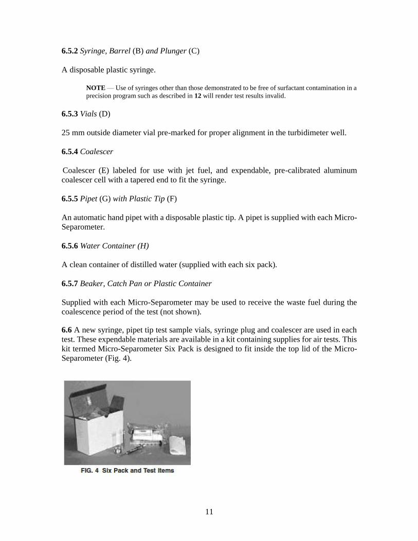
6.6 A new syringe, pipet tip test sample vials, syringe plug and coalescer are used in each
test. These expendable materials are available in a kit containing supplies for air tests. This
kit termed Micro-Separometer Six Pack is designed to fit inside the top lid of the Micro-
Separometer (Fig. 4).
12
7 REAGENTS
7.1 Aerosol OT — Solid (100 % dry) bis-2 ethylhexyl sodium sulfosuccinate
7.2 Dispersing Agent —Toluene solution containing 1 mg of Aerosol OT per milliliter of toluene.
7.3 Reference Fluid
7.3.1 (For checking the operational performance of the Micro separometer instrumentation) Consist
of increasing concentrations (0 to 1.2 ml/l) of dispersing agent added to the reference fluid
NOTE — Reference Fluid Base is a surfactant-free clean hydrocarbon material which is used to
verify proper operation and is prepared in the manner described in Appendix A.
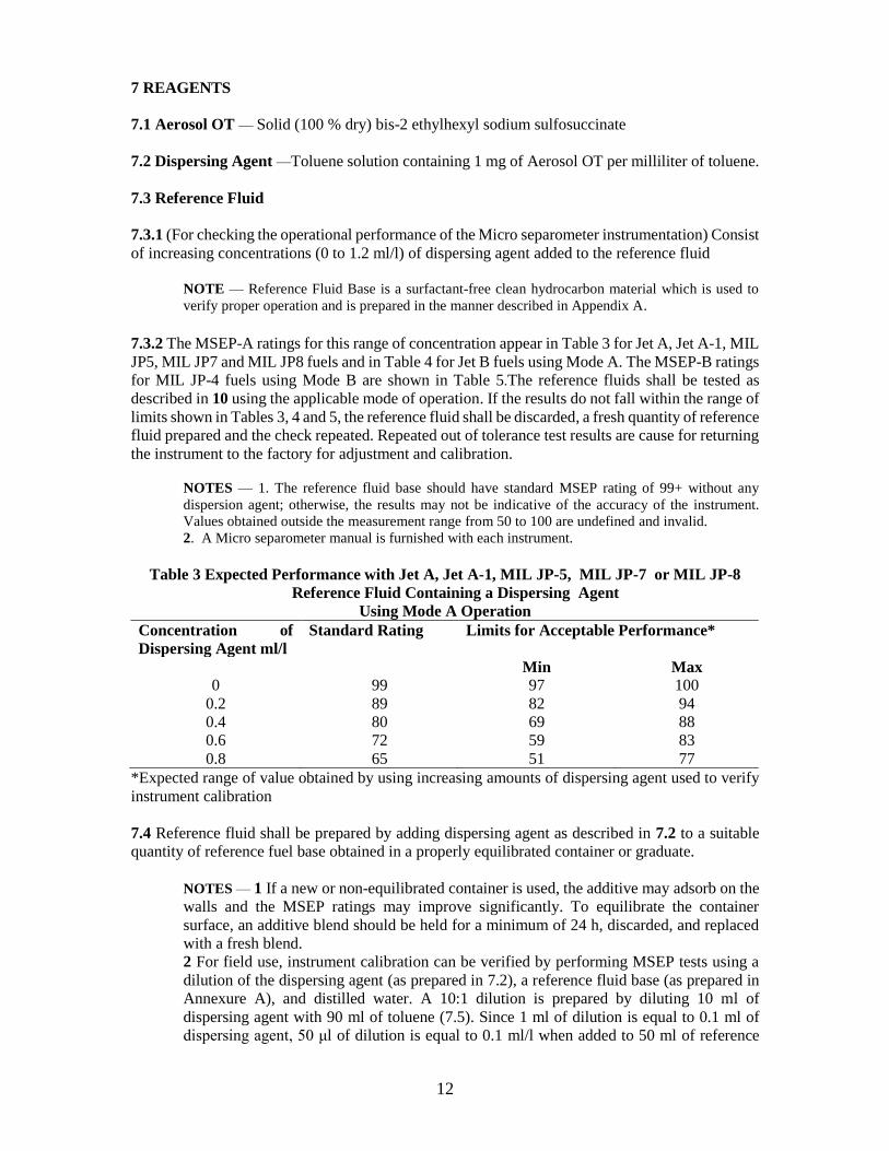
7.3.2 The MSEP-A ratings for this range of concentration appear in Table 3 for Jet A, Jet A-1, MIL
JP5, MIL JP7 and MIL JP8 fuels and in Table 4 for Jet B fuels using Mode A. The MSEP-B ratings
for MIL JP-4 fuels using Mode B are shown in Table 5.The reference fluids shall be tested as
described in 10 using the applicable mode of operation. If the results do not fall within the range of
limits shown in Tables 3, 4 and 5, the reference fluid shall be discarded, a fresh quantity of reference
fluid prepared and the check repeated. Repeated out of tolerance test results are cause for returning
the instrument to the factory for adjustment and calibration.
NOTES — 1. The reference fluid base should have standard MSEP rating of 99+ without any
dispersion agent; otherwise, the results may not be indicative of the accuracy of the instrument.
Values obtained outside the measurement range from 50 to 100 are undefined and invalid.
2. A Micro separometer manual is furnished with each instrument.
Table 3 Expected Performance with Jet A, Jet A-1, MIL JP-5, MIL JP-7 or MIL JP-8
Reference Fluid Containing a Dispersing Agent
Using Mode A Operation
Concentration of
Dispersing Agent ml/l
Standard Rating Limits for Acceptable Performance*
Min Max 0 99 97 100
0.2 89 82 94
0.4 80 69 88
0.6 72 59 83
0.8 65 51 77
*Expected range of value obtained by using increasing amounts of dispersing agent used to verify
instrument calibration
7.4 Reference fluid shall be prepared by adding dispersing agent as described in 7.2 to a suitable
quantity of reference fuel base obtained in a properly equilibrated container or graduate.
NOTES — 1 If a new or non-equilibrated container is used, the additive may adsorb on the
walls and the MSEP ratings may improve significantly. To equilibrate the container
surface, an additive blend should be held for a minimum of 24 h, discarded, and replaced
with a fresh blend.
2 For field use, instrument calibration can be verified by performing MSEP tests using a
dilution of the dispersing agent (as prepared in 7.2), a reference fluid base (as prepared in
Annexure A), and distilled water. A 10:1 dilution is prepared by diluting 10 ml of
dispersing agent with 90 ml of toluene (7.5). Since 1 ml of dilution is equal to 0.1 ml of
dispersing agent, 50 μl of dilution is equal to 0.1 ml/l when added to 50 ml of reference
13
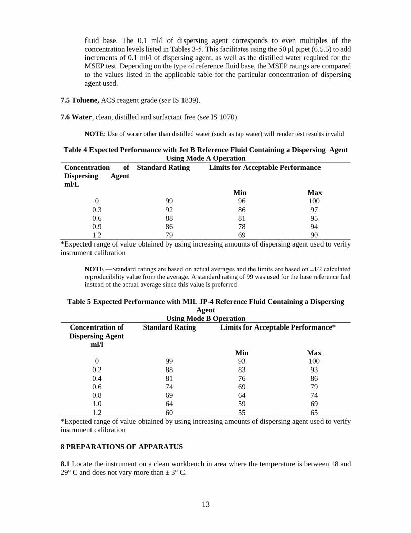
fluid base. The 0.1 ml/l of dispersing agent corresponds to even multiples of the
concentration levels listed in Tables 3-5. This facilitates using the 50 μl pipet (6.5.5) to add
increments of 0.1 ml/l of dispersing agent, as well as the distilled water required for the
MSEP test. Depending on the type of reference fluid base, the MSEP ratings are compared
to the values listed in the applicable table for the particular concentration of dispersing
agent used.
7.5 Toluene, ACS reagent grade (see IS 1839).
7.6 Water, clean, distilled and surfactant free (see IS 1070)
NOTE: Use of water other than distilled water (such as tap water) will render test results invalid
Table 4 Expected Performance with Jet B Reference Fluid Containing a Dispersing Agent
Using Mode A Operation
Concentration of
Dispersing Agent
ml/L
Standard Rating Limits for Acceptable Performance
Min Max
0 99 96 100
0.3 92 86 97
0.6 88 81 95
0.9 86 78 94
1.2 79 69 90
*Expected range of value obtained by using increasing amounts of dispersing agent used to verify
instrument calibration
NOTE —Standard ratings are based on actual averages and the limits are based on ±1⁄2 calculated
reproducibility value from the average. A standard rating of 99 was used for the base reference fuel
instead of the actual average since this value is preferred
Table 5 Expected Performance with MIL JP-4 Reference Fluid Containing a Dispersing
Agent
Using Mode B Operation
Concentration of
Dispersing Agent
ml/l
Standard Rating Limits for Acceptable Performance*
Min Max
0 99 93 100
0.2 88 83 93
0.4 81 76 86
0.6 74 69 79
0.8 69 64 74
1.0 64 59 69
1.2 60 55 65
*Expected range of value obtained by using increasing amounts of dispersing agent used to verify
instrument calibration
8 PREPARATIONS OF APPARATUS
8.1 Locate the instrument on a clean workbench in area where the temperature is between 18 and
29° C and does not vary more than ± 3° C.
14
8.2 Open the case and remove the six-pack box from the lid. Raise the right panel until completely
vertical and locked in place. If ac power is available, connect the power cord and turn the instrument
on. If the internal battery power is used, assure that the batteries are charged sufficiently to perform
the desired number of test. Low battery power is indicated when the power lamp does not
illuminate. Connect the instrument to an AC power source for at least 16 h (full charge) prior to
use. Approximately 25 tests can then be performed
NOTE —If the battery in MS type 1 is not charged sufficiently to run a test, an ERR-06 will be
displayed indicating that the battery must be recharged.
8.2.1 Type 1 & 2 instruments are turned on by depressing the switch (pushbutton) marked ON. The
ON power indicator light will alternately pulse on and off when the instrument is connected to an
ac power source and will stay on continuously when operated by the battery pack. Flickering of the
power indicator light, during any portion of a test sequence being performed using battery power,
indicated that recharging is necessary.
8.3 Have ready a supply of syringes, vials, coalescers, syringe plugs, and pipet tips, as well as a
clean container with distilled water. All of the items except the container and water are furnished
in the six pack provided with the instrument. In addition, have the pipet readily available.
8.4 Syringe drive travel times during the coalescing test period were initially calibrated at the
factory for each mode of operation and have a significant bearing on the final test results. MS type
1 & 2 these instruments have self-check circuitry to detect out of tolerance syringe drive travel
times.
NOTES—1 Syringe drive travel times exceeding the upper limit will cause the final results to
measure high; conversely, travel times below the lower limit cause the final results to measure low.
2 A Micro separometer operation manual is furnished with each instrument.
8.4.1 MS Type-1
The alert indicator lamp (marked SYR) illuminates and depending on the degree (more
than 3 s) of the out of tolerance condition, three short (1 s) tones will also sound. An
occasional out of tolerance alert may be experienced due to some intermittent condition
which, probably, will not be indicative of instrument failure. However, repeated alerts are
cause for returning the instrument to the factory for adjustment.
8.4.2 MS Type-1
During a test, the error alert indicator will illuminate and ERR-03 will be displayed
indicating an out of tolerance syringe travel time. Error alerts ERR-01 and ERR-02 will be
displayed if the syringe stalls while traveling up or down, respectively.
9. SAMPLE PREPARATION
9.1 Under no circumstances shall test fuel be pre-filtered as filter media can remove the
very materials, surfactants, that the test method is designed to detect. If the test fuel is
contaminated with particulate matter, allow such materials to settle out of the fuel before
testing.
15
9.2 Special precautions concerning sample containers and sampling technique are
discussed in Annex B. Extreme care and cleanliness are required in taking samples either
directly into the test syringe or into a sample container. Before pouring the test sample
from the container, wipe the container outlet thoroughly with a clean, lintless wiper; pour
the test sample into a clean beaker or directly into the barrel of the test syringe.
NOTE —Test method results are shown to be sensitive to trace contamination from sampling
containers.
9.3 If the sample for test is not within the test temperature limits, 18 °C to 29 °C, allow the
sample to stand until an intolerance temperature is attained.
10 PROCEDURE
10.1 Select either Mode A or B operation. (Refer to Table 1 for applicable Mode for a
specific fuel.)
NOTE — Only JP-4 requires Mode B operation
10.2 Remove a plunger from a new 50 ml syringe and wipe the tip using a clean, lintless
wipe to remove any sheen caused by excess lubricant. Insert a plug into the tapered bottom
of the syringe barrel, add 50±1 ml of fuel and place the syringe barrel on the emulsifier
mount turning to lock in place. Ensure that the syringe barrel is properly aligned
concentrically with the mixer shaft and is not touching the propeller.
10.2.1 To mitigate the buildup of static charge, only nitrile gloves are recommended for
use while handling the syringe barrel.
10.2.2 Ensure that the syringe barrel is properly aligned concentrically with the mixer shaft.
Proper alignment can be verified by grasping the syringe barrel and moving the same until
the propeller on the end of the mixer shaft is free and not touching. Misalignment can cause
plastic shavings to form and collect on the coalescer filter material resulting in erroneous
test results.
10.3 Initiate the first CLEAN cycle by depressing the START (Type 1) or CLEAN 1 (Type
2) pushbutton as designated by the annunciator light.
NOTE — 1. The type 2 will illuminate ERROR ALERT and display an ERR-05 when the emulsifier
speed is outside of acceptable limits.
2. Do not operate the mixer without having a syringe with fuel in place. The mixer bearings depend
on the fuel for lubrication.
10.4 At the end of the first clean cycle, when the mixer motor stops, remove the syringe
barrel from the emulsifier, discard the fuel, and drain the syringe thoroughly. Add 50 ml±
1 ml of fresh fuel into the syringe and place the syringe barrel on the emulsifier mount (turn
to lock in place). Visually inspect that the syringe barrel is properly aligned concentrically
with the mixer shaft and is not touching the propeller.
10.5 Second Clean Cycle
16
10.5.1 Type 1 — Initiate the second CLEAN cycle by sequentially pressing the RESET, A
or B, and the START pushbuttons, as designated by the annunciator light.
10.5.2 Type 2 — Initiate the second CLEAN cycle by pressing the CLEAN 2 pushbutton.
10.6 Add about 15 to 20 ml of the fuel to be tested into new vial. Wipe the outside of the
vial with a clean, lintless wiper and insert the vial into the turbidimeter well aligning the
black mark on the vial at 90° from the white line on the front of the turbidimeter well.
Rotate the vial until the black mark on the vial aligns with the white line on the front of the
turbidimeter well.
10.7 At the end of the second clean cycle, when the mixer motor stops, remove the syringe
barrel from the emulsifier, discard the fuel and drain the syringe thoroughly Add 50 ± 1 ml
of fresh fuel sample into the syringe.
NOTE— Handle the syringe in such a manner as to minimize warming of the fuel sample by body
heat.
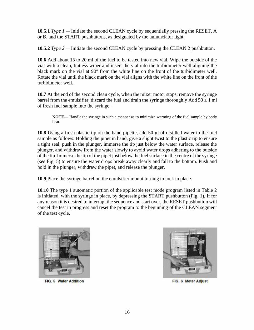
10.8 Using a fresh plastic tip on the hand pipette, add 50 μl of distilled water to the fuel
sample as follows: Holding the pipet in hand, give a slight twist to the plastic tip to ensure
a tight seal, push in the plunger, immerse the tip just below the water surface, release the
plunger, and withdraw from the water slowly to avoid water drops adhering to the outside
of the tip Immerse the tip of the pipet just below the fuel surface in the centre of the syringe
(see Fig. 5) to ensure the water drops break away clearly and fall to the bottom. Push and
hold in the plunger, withdraw the pipet, and release the plunger.
10.9 Place the syringe barrel on the emulsifier mount turning to lock in place.
10.10 The type 1 automatic portion of the applicable test mode program listed in Table 2
is initiated, with the syringe in place, by depressing the START pushbutton (Fig. 1). If for
any reason it is desired to interrupt the sequence and start over, the RESET pushbutton will
cancel the test in progress and reset the program to the beginning of the CLEAN segment
of the test cycle.
17
10.10.1 The automatic program starts with a read meter indication (four short tones)
followed by a 10 s full-scale adjustment period. During this period adjust the meter to read
100 (see Fig. 6). If the adjustment cannot be completed at this time, final adjustment can
be accomplished during the second meter adjust period occurring later in the test sequence.
10.10.2 After the full-scale adjustment period, the mixer motor activates and the emulsion
process is initiated.
NOTE—A few drops of fuel may seep from the hole in the emulsifier head during the high-speed
mixing operation. This should not affect the test results.
10.11 The type 2 automatic portion of the applicable test mode program listed in Table 2
is initiated, with the syringe in place, by depressing the RUN pushbutton.
10.11.1 The automatic program starts with a read meter indication (four short tones)
followed by a 2 s to 30 s adjustment period. During this period, the turbidimeter will
automatically adjust to 100. If the adjustment cannot be completed at this time, the ERROR
ALERT will illuminate and an ERR-04 will be displayed.
10.12 After the full-scale adjustment period, the mixer motor (on both the type 1 and type
2) activates and the emulsion process is initiated.
10.13 When the mixer stops (after emulsification), remove the syringe barrel from the
emulsifier and partially insert the plunger to seal the open end of the syringe. Invert the
syringe (exit hole up), remove the plug, and exhaust the entrapped air in the syringe barrel
without significant fuel loss by carefully inserting plunger to the 50 ml mark. (Use a clean
wipe over the exit hole to capture the small amounts of fuel which may be extruded as
foam.) Affix a new coalescer to the end of the syringe barrel.
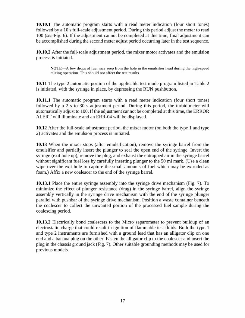
10.13.1 Place the entire syringe assembly into the syringe drive mechanism (Fig. 7). To
minimize the effect of plunger resistance (drag) in the syringe barrel, align the syringe
assembly vertically in the syringe drive mechanism with the end of the syringe plunger
parallel with pushbar of the syringe drive mechanism. Position a waste container beneath
the coalescer to collect the unwanted portion of the processed fuel sample during the
coalescing period.
10.13.2 Electrically bond coalescers to the Micro separometer to prevent buildup of an
electrostatic charge that could result in ignition of flammable test fluids. Both the type 1
and type 2 instruments are furnished with a ground lead that has an alligator clip on one
end and a banana plug on the other. Fasten the alligator clip to the coalescer and insert the
plug in the chassis ground jack (Fig. 7). Other suitable grounding methods may be used for
previous models.
18
10.14 Four short tones will indicate the second meter adjust period. If required (type 1),
the operator should adjust the meter reading to 100. The syringe drive mechanism will start
down at the end of the meter adjust period forcing the water/ fuel emulsion through the
coalescer (fig.7). During this operation remove the vial from the turbidimeter well and
discard the fuel.
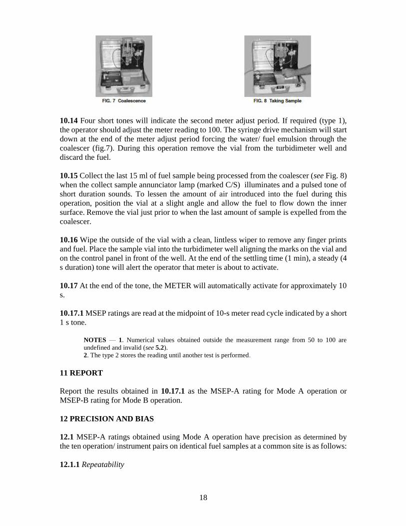
10.15 Collect the last 15 ml of fuel sample being processed from the coalescer (see Fig. 8)
when the collect sample annunciator lamp (marked C/S) illuminates and a pulsed tone of
short duration sounds. To lessen the amount of air introduced into the fuel during this
operation, position the vial at a slight angle and allow the fuel to flow down the inner
surface. Remove the vial just prior to when the last amount of sample is expelled from the
coalescer.
10.16 Wipe the outside of the vial with a clean, lintless wiper to remove any finger prints
and fuel. Place the sample vial into the turbidimeter well aligning the marks on the vial and
on the control panel in front of the well. At the end of the settling time (1 min), a steady (4
s duration) tone will alert the operator that meter is about to activate.
10.17 At the end of the tone, the METER will automatically activate for approximately 10
s.
10.17.1 MSEP ratings are read at the midpoint of 10-s meter read cycle indicated by a short
1 s tone.
NOTES — 1. Numerical values obtained outside the measurement range from 50 to 100 are
undefined and invalid (see 5.2).
2. The type 2 stores the reading until another test is performed.
11 REPORT
Report the results obtained in 10.17.1 as the MSEP-A rating for Mode A operation or
MSEP-B rating for Mode B operation.
12 PRECISION AND BIAS
12.1 MSEP-A ratings obtained using Mode A operation have precision as determined by
the ten operation/ instrument pairs on identical fuel samples at a common site is as follows:
12.1.1 Repeatability
19
The difference between successive measured MSEP-A rating obtained by the same
operator with the same Micro separometer under constant operating conditions on identical
test material would, in the long run and in the normal and correct operation of the test
method, exceed the following values for only one case in twenty (see Note1).
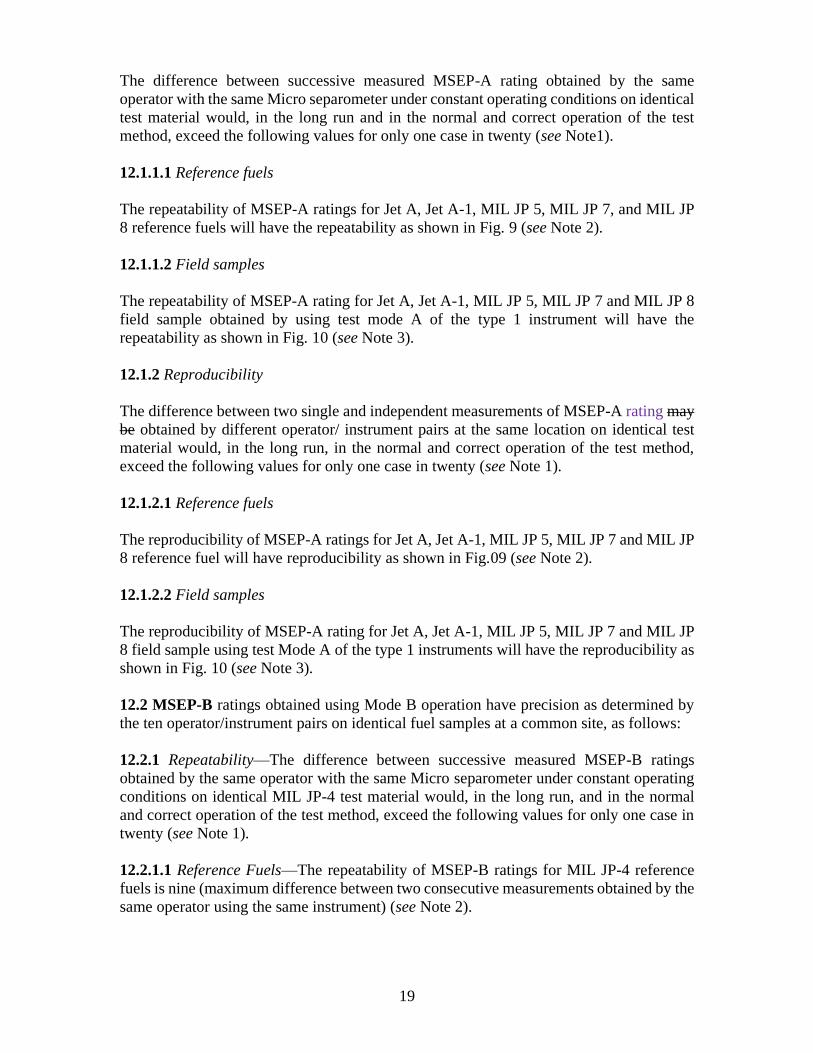
12.1.1.1 Reference fuels
The repeatability of MSEP-A ratings for Jet A, Jet A-1, MIL JP 5, MIL JP 7, and MIL JP
8 reference fuels will have the repeatability as shown in Fig. 9 (see Note 2).
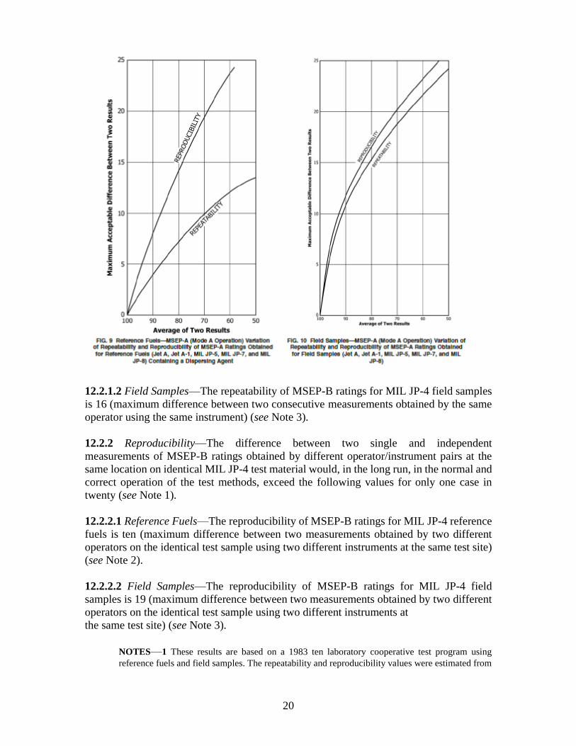
12.1.1.2 Field samples
The repeatability of MSEP-A rating for Jet A, Jet A-1, MIL JP 5, MIL JP 7 and MIL JP 8
field sample obtained by using test mode A of the type 1 instrument will have the
repeatability as shown in Fig. 10 (see Note 3).
12.1.2 Reproducibility
The difference between two single and independent measurements of MSEP-A rating may
be obtained by different operator/ instrument pairs at the same location on identical test
material would, in the long run, in the normal and correct operation of the test method,
exceed the following values for only one case in twenty (see Note 1).
12.1.2.1 Reference fuels
The reproducibility of MSEP-A ratings for Jet A, Jet A-1, MIL JP 5, MIL JP 7 and MIL JP
8 reference fuel will have reproducibility as shown in Fig.09 (see Note 2).
12.1.2.2 Field samples
The reproducibility of MSEP-A rating for Jet A, Jet A-1, MIL JP 5, MIL JP 7 and MIL JP
8 field sample using test Mode A of the type 1 instruments will have the reproducibility as
shown in Fig. 10 (see Note 3).
12.2 MSEP-B ratings obtained using Mode B operation have precision as determined by
the ten operator/instrument pairs on identical fuel samples at a common site, as follows:
12.2.1 Repeatability—The difference between successive measured MSEP-B ratings
obtained by the same operator with the same Micro separometer under constant operating
conditions on identical MIL JP-4 test material would, in the long run, and in the normal
and correct operation of the test method, exceed the following values for only one case in
twenty (see Note 1).
12.2.1.1 Reference Fuels—The repeatability of MSEP-B ratings for MIL JP-4 reference
fuels is nine (maximum difference between two consecutive measurements obtained by the
same operator using the same instrument) (see Note 2).
20
12.2.1.2 Field Samples—The repeatability of MSEP-B ratings for MIL JP-4 field samples
is 16 (maximum difference between two consecutive measurements obtained by the same
operator using the same instrument) (see Note 3).
12.2.2 Reproducibility—The difference between two single and independent
measurements of MSEP-B ratings obtained by different operator/instrument pairs at the
same location on identical MIL JP-4 test material would, in the long run, in the normal and
correct operation of the test methods, exceed the following values for only one case in
twenty (see Note 1).
12.2.2.1 Reference Fuels—The reproducibility of MSEP-B ratings for MIL JP-4 reference
fuels is ten (maximum difference between two measurements obtained by two different
operators on the identical test sample using two different instruments at the same test site)
(see Note 2).
12.2.2.2 Field Samples—The reproducibility of MSEP-B ratings for MIL JP-4 field
samples is 19 (maximum difference between two measurements obtained by two different
operators on the identical test sample using two different instruments at
the same test site) (see Note 3).
NOTES—1 These results are based on a 1983 ten laboratory cooperative test program using
reference fuels and field samples. The repeatability and reproducibility values were estimated from
21
results obtained at the some location and on several consecutive days, by different operator/
instrument pairs testing identical samples. Results particularly for reproducibility obtained at
different times and locations may, therefore, not be comparable according to these estimates, since
they may contain errors due to sampling and environmental factors.
In practice, two results obtained at different laboratories (location) would be acceptable if their
difference did not exceed the published reproducibility. In the event that the difference did exceed
the reproducibility there would be no means of testing whether the results were acceptable or not.
The need for additional cooperative testing to establish reproducibility when samples are shipped
between laboratories (and therefore may not be identical at the time of testing) is being studied.
2 This result is based on a laboratory cooperative test program using reference fluids prepared in
accordance with Annex A.
3 These results are based on a laboratory cooperative test program using TYPE A (field samples of
MIL JP 5) fuels containing fuel system corrosion and icing inhibitors. Due to large number of
additive combinations and concentrations, there may be field samples other than those used to
develop the precision of this test method, that may not respond within the expected limit.
4 The results of precision program with the Micro separometer and its correlation with correlation
with other rating methods are discussed in Annex C.
12.2 Bias
The procedure in this test method has no bias, because the value of MSEP is defined only
in terms of this method.
Annex A
(Clause 7.3)
PREPARATION OF REFERENCE FLUID BASE
A-1 GENERAL
This procedure describes the preparation within an 8 h day of a 20 l (5 gal) lot of reference
fluid base. This procedure has been found to give a filtrate having 100 MSEP rating.
A-2 SUMMARY OF PROCEDURE
A fuel is flowed at a constant rate through a fresh column of granular clay and collected in
a clean storage receiver. The fuel should conform to Jet A, Jet A-1 or Jet B and the aromatic
content should be between 10 and 20 volume percent. Reference fluids may also be of MIL
JP 4, MIL JP 5, MIL JP 7 and MIL JP 8 fuel origin. Additional processing such as water
washing followed by flowing the fuel through a salt bed prior to clay treating may be
required to attain a standard 99+ rating and, the AOT Standard Ratings shown in Tables 3-
5.
A-3 APPARATUS
A-3.1 Glass Column
22
Containing a sealed-in coarse fritted glass disk near the bottom and with a 4-mm metering
type TFE- fluorocarbon stopcock outlet at the bottom. The inside diameter of the column
is 55 to 65 mm, and the length above the fritted disk shall be at least 1 m.
A-3.2 Siphon
Glass tubing having an outside diameter of 5 to 10 mm with the legs 100 to 150 mm apart.
The suction leg shall be 380 to 400 mm long to reach the bottom of the feed container. The
other leg shall be 50 to 100 mm longer.
A-3.3 Feed Container
A standard square or round 20 l (5 gal) epoxy – lined can in which the sample is obtained.
A-3.4 Receiver Can
A new 20 l (5 gal) epoxy – lined can or one which has been used only with clay – filtered
fuel. Plastic containers shall not be used.
A-3.5 Funnel
With a 10 to 20 mm outlet.
A-3.6 Graduated Cylinder, 0.5 to 1 l capacity.
A-3.7 Graduated Cylinder, 50 to 100 ml capacity.
A-3.8 Beaker, 2 l capacity
A-4 MATERIALS
A-4.1 Attapulgus Clay
30/60 mesh, LVM (calcined) grade or equal. Store the clay protected from atmospheric
moisture and avoid handling that will cause particle size segregation.
A-4.2 Fine Glass Wool
A-4.3 Isopropyl Alcohol – 90 percent
A-4.4 Toluene – in a squeeze bottle.
NOTE—Warning: Flammable. Vapour harmful.
A-4.5 Water — preferably distilled.
A-4.6 Salt—Rock salt or equivalent.
23
A-5 PREPARATION OF APPARATUS
A-5.1 Mount the column vertically. Measure approximately 500 ml of clay in the graduated
cylinder, tapping gently to settle.
A-5.2 Place the funnel on top, the column with its outlet centered. Quickly pour the clay
into the funnel, aiming the funnel so that the clay falls in the centre of the column. Remove
the funnel and tap the column gently all around to settle and level the clay bed. Tamp a
fist-sized wad of glass wool carefully down on top of the bed.
A-5.3 When water washing of the fuel is required, place approximately 12.5 to 15.0 mm
of salt on top of the wad of glass wool and then another wad of glass wool on top of the
salt.
A-6 FILTRATION PROCEDURE
A-6.1 Position a full 20 l (5 gal) feed container with its opening level with the top of the
column. Remove the cap and insert the siphon, short leg in the can, longer leg in the
column.
A-6.2 Place the 2 l beaker under the column.
A-6.3 Make sure the column stopcock is wide open. Put slight air pressure in the feed can
to start the siphon. The glass wool packing should prevent the clay bed from being
disturbed at startup.
NOTE—In a well-prepared column, the fuel may be seen to advance down the column in a nearly
horizontal plane; no bubbles will rise through the clay. If the advancing front is tilted more than 45°
or there is much bubbling, the quality of the percolation may be impaired.
A-6.4 As soon as the fuel is flowing through the column outlet, adjust the metering screw
to attain a rate of 50 to 60 ml/min. Check by measuring with the small graduated cylinder
for 1min or 2 min intervals.
A-6.5 When at least 1l has been collected, turn off the stopcock without disturbing the
metering screw setting. Remove the beaker and support the 20l (5 gal) receiver can under
the column so that the outlet tube extends about 10 mm into the opening. Open the
stopcock. Protect the opening from dirt.
NOTE—Warning: When percolating flammable fuel, seal between the outlet and receiver opening
with aluminum foil, ground the receiver, and purge it with dry nitrogen before starting flow into it.
A similar purge of the column before the step in A-6.3 is desirable.
A-6.6 Recycle the beaker of filtrate to the feed can or discard it.
A-6.7 When the level of fuel has dropped nearly to the top of the clay bed, turn off the
stopcock, remove, and cap the receiver can.
A-6.8 For lengthy storage, purge the receiver can with dry nitrogen.
24
NOTE— At the specified flow rate, the 20 l (5 gal) percolation will be in 6 to 6½ h running time.
A-7 CLEAN THE COLUMN
A-7.1 Drain the column.
A-7.2 Dismount the column, open it over a solid waste can, and with the stopcock wide
open, below out the clay.
A-7.3 With the column inverted over a liquid waste receiver, run alcohol from the squeeze
bottle into the outlet. Tilt the column to rinse the entire disk area and the entire inside of
the column. When the clay residue has been entirely rinsed out, disassemble and rinse the
stopcock parts, dry and reassemble them and blow the entire assembly dry.
A-7.4 If the column still appears dirty, rinse it thoroughly with hot water, then with distilled
water, invert it and rinse as in A-7.3 with alcohol, then with acetone and blow dry. This
should seldom be necessary.
A-8 WATER WASHING THE BASE FUEL
A-8.1 Scope
Occasionally it may become necessary to further process the base fuel to prevent
interaction between AOT and fuel additives not removed by the clay treatment. Base fuels
containing icing inhibitors typically require this type of processing.
A-8.2 Summary of Procedure
A given amount of water is mixed with the base fuel and is then allowed to stand for a
period of time to let the fluids separate into layers. The water is then removed and the fuel
is processed as described in A-6.
A-8.3 Procedure
A-8.3.1 Mix 0.95 l (1 qt) of water (A-4) thoroughly with 19 l (5 gal) of base fuel by
agitating by any convenient means.
A-8.3.2 Allow the container to stand for sufficient time to allow the water to completely
settle out of the bottom of the container.
A-8.3.3 Remove the water from the bottom of the container using a pump, pipet, or any
other means available.
A-8.3.4 Repeat A-8.3.1, A-8.3.2 and A-8.3.3 as required, to assure removal of all water
soluble substances and then proceed to the filtration process.
25
A-8.3.5 Initiate the filtration process of A-6 using a filtration media prepared as described
in A-5.3.
ANNEX B
(Clause 9.2)
SAMPLING TECHNIQUE
B-1 For any test that seeks the presence of trace constituents, steps must be taken to ensure
testing of a representative sample. The round-robin precision study for these test methods
showed that flushing of the sampling container was most important. This indicates that
trace amounts of surfactant material in aviation turbine fuels can be absorbed on, or
desorbed from, metal surface. A suggested technique for taking separometer samples
follows; it has been found to give representative samples. Any similar approach should be
satisfactory. The technique is shown here only as a guide to good practice.
B-2 SAMPLE CONTAINER
This should be a scrupulously clean metal can, preferably epoxy-lined. The size will be
governed by the number of replicate tests to be run.
NOTE—New cans, not epoxy-lined, are sometimes coated with surfactant type roll oils or solder
flux residues which can affect MSEP test results. Epoxy cans also may have mold release or similar
residues which can also affect the MSEP test results. Such cans can usually be cleaned by three
consecutive rinses with the fuel to be sampled prior to taking the sample for test. Preferably the
sample container should be filled with the same grade of fuel to be sampled (filtered through at least
an 0.8 µm membrane filter) and allowed to stand for atleast 24 h. The fuel should be disposed of
and the sample container flushed with the fuel to be tested prior to taking the sample.
B-2.1 Sample Source
Draw the sample from a moving stream of fuel whose source is removed from tank water
bottoms by as great a distance as feasible.
B-2.2 Sample Line
The line may consist of a short 6.4 to 12.7 mm (1/4 to ½ in) diameter tube with its open
end facing the moving stream. The other end (outside the pipe) should be equipped with a
suitable shutoff valve and spout. In turbulent fuel streams, it has been determined that
sampling taps flush with the pipe wall are satisfactory.
B-2.3 Taking the Sample
Flush the sample line with at least 0.95 l (1 qt) of the fuel to be sampled. Open and close
the sample valve several times. Rinse the sample can with three separate 0.95 l amounts of
the fuel to be sampled (for a 1 gal can). Include the cap and inner seal, if used, in the rinsing.
Draw the sample and put the cap in place.
26
ANNEX C
(Clause 5.3)
CORRELATION OF MICRO-SEPAROMETER MSEP-A RATINGS
C-1 INTRODUCTION
The program to establish the precision of the Micro separometer involved cooperative
testing by the ten laboratories using seven Jet A blends and seven Jet B blends and parallel
testing with Field Test Method. The correlation MSEP-A Ratings is shown below.
C-1.1 Earlier programs with Field Test Method involved cooperative testing in conjunction
with Test Method IS 1448 [P: 137]. Correlation of MSS Ratings with WSIM Ratings
established at that time have been extended to MSEP-A Ratings using the MSS rating as
the common reference.
C-2 PRECISION OF MSEP-A RATINGS
C-2.1 Using fuels that simulated field experience by addition of corrosion inhibitors, etc
as well as reference blends prepared in accordance with 7.4, the precision of the Micro
separometer was shown to be equivalent to the precision of Field Test Method Minisonic
separometer.
C-2.2 Analysis revealed that precision of MSEP-A Ratings varies with rating levels as
shown in Fig. 9 & 10 , which was developed originally for Test Method IS 1448 [P: 137]
and confirmed with Field Test Method.
C-3 CORRELATION OF MSEP-A AND MSS RATINGS
C-3.1 The relationship between the MSEP-A and MSS Ratings is a function of fuel type
as described in the following equations:
MSEP-A (Jet A) = 1.276 (MSS) – 23.805
MSEP-A (Jet A) = 1.338 (MSS) – 32.366
MSEP-A (both fuels) = 1.247 (MSS) – 22.952
C-4 MSEP-A RATINGS LEVEL VERSUS FUEL TYPE
C-4.1 The Micro separometer Rating level for Jet B fuel is higher than Jet A fuel using
either the standard dispersing agent (see 7.3) or other additives typical of fuels in the field.
Using Field Test Method MSS Ratings as the common reference, the MSEP-A relationship
for Jet B fuel containing standard dispersing agents is as follows:
MSEP-A (JET B) = 0.60 WSIM + 40
C-5 CORRELATION OF MSEP-A RATINGS WITH FIELD EXPERIENCE

27
Fuel blends that simulate field samples field samples reveal that fuels containing corrosion
inhibitors exhibit higher MSEP-A Ratings than blends with other additives including
standard dispersing agents.