Embed Size (px)
Citation preview
DRAFT Mine Methane Capture Initiative Protocol
Capture and Destruction of Mine Methane from Drainage and Ventilation Systems at Active Coal
Mines
Protocol Version [Draft]
Draft Mine Methane Capture Initiative Protocol February 2018
Table of Contents Abbreviations and Acronyms ...................................................................................................... 2
1 Introduction ......................................................................................................................... 3
2 Definitions ........................................................................................................................... 3
3 MMC GHG Reduction Initiative ........................................................................................... 4
3.1 Initiative Definition ........................................................................................................ 4
3.1.1 Drainage Initiatives ............................................................................................... 5
3.1.2 Ventilation Air Methane Initiatives ......................................................................... 6
3.2 Initiative Start Date ....................................................................................................... 6
4 Eligibility .............................................................................................................................. 7
4.1 General Requirements ................................................................................................. 7
4.2 Location ....................................................................................................................... 7
4.2.1 Performance Standard Test .................................................................................. 7
5 GHG Assessment Boundary ............................................................................................... 8
6 Calculation of Emission Reductions ...................................................................................16
6.1 Calculation of Emission Reductions from Active Drainage Initiatives ..........................16
6.1.1 Calculation of Baseline Emissions from Active Drainage Initiatives ......................17
6.1.2 Calculation of Initiative Emissions from Active Drainage Initiatives ......................19
6.2 Calculation of Emission Reductions from Ventilation Air Methane Initiatives ...............22
6.2.1 Calculation of Baseline Emissions from Ventilation Air Methane Initiatives ..........22
6.2.2 Calculation of Initiative Emissions from Ventilation Air Methane Initiatives ...........23
7 Data Management and Monitoring ....................................................................................25
7.1 Data Collection ...........................................................................................................25
7.2 Monitoring Requirements ............................................................................................26
7.2.1 General ................................................................................................................26
7.2.2 Arrangement of Metering Equipment ...................................................................28
7.3 Instrument Quality Assurance and Quality Control (QA/QC) .......................................29
7.4 Missing Data ...............................................................................................................30
7.5 Monitoring Parameters ................................................................................................30
8 Reversals ...........................................................................................................................35
8.1 Reversals Listed for the Purposes of s. 20(1) paragraph 1 ..........................................35
8.2 Errors, Omissions or Misstatements............................................................................35
9 Reporting ...........................................................................................................................35
9.1 Initiative Report ...........................................................................................................35
9.1.1 Monitoring Information .........................................................................................35
9.1.2 Quantification Information ....................................................................................36
Draft Mine Methane Capture Initiative Protocol February 2018
9.2 Reversal Report ..........................................................................................................36
9.2.1 General ................................................................................................................36
9.2.2 Quantification Information ....................................................................................36
10 Record Keeping ..............................................................................................................36
Appendix A Parameters for Quantification ...........................................................................38
A.1 Methane Destruction ...................................................................................................38
A.2 Methane Density .........................................................................................................38
Appendix B Missing Data – Substitution Methods................................................................39
Draft Mine Methane Capture Initiative Protocol February 2018
List of Tables Table 4.1. Description of all Sources, Sinks, and Reservoirs .....................................................11 Table 7.1. Mine Methane Initiative Monitoring Plan ...................................................................30 Table A.1. Destruction Efficiencies for Destruction Devices ......................................................38 Table A.2. Density of Methane at Reference Conditions ...........................................................38 Table B.1. Missing Data – Substitution Methods .......................................................................40
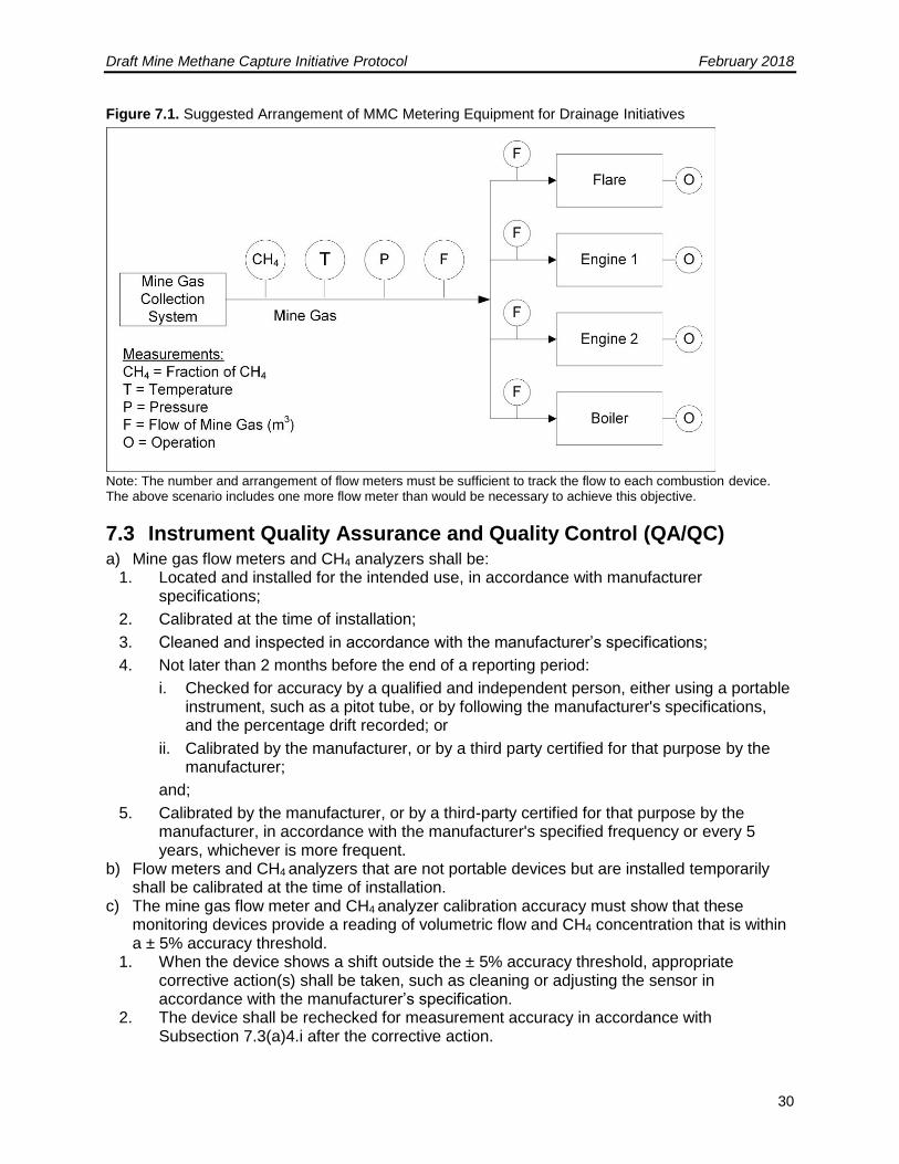
List of Figures Figure 4.1. GHG Assessment Boundary for Active Underground and Active Surface Mines ...... 9 Figure 4.2. GHG Assessment Boundary for Ventilation Air Methane Mines ..............................10 Figure 7.1. Suggested Arrangement of MMC Metering Equipment for Drainage Initiatives .......29
List of Equations Equation 6.1. GHG Emission Reductions ..................................................................................16 Equation 6.2. Adjusting Mine Gas Flow for Temperature and Pressure ....................................16 Equation 6.3. Calculating Baseline Emissions ...........................................................................17 Equation 6.4. Baseline Methane Released to Atmosphere ........................................................18 Equation 6.5. Baseline emissions from Pre-Initiative Destruction Devices .................................19 Equation 6.6. Calculating Initiative Emissions ...........................................................................19 Equation 6.7. Initiative Emissions from Fossil Fuels ..................................................................20 Equation 6.8. Initiative Emissions from Electricity Use ..............................................................20 Equation 6.9. Initiative Emissions from Destruction of Captured Methane .................................21 Equation 6.10. Initiative Emissions from Uncombusted Methane ..............................................21 Equation 6.11. GHG Emission Reductions ................................................................................22 Equation 6.12. Calculating Baseline Methane Emissions ..........................................................22 Equation 6.13. Calculating Initiative Emissions .........................................................................23 Equation 6.14. Initiative Emissions from Fossil Fuels ................................................................23 Equation 6.15. Initiative Emissions from Electricity Use ............................................................24 Equation 6.16. Ventilation Air Leaving the Destruction Device ..................................................24 Equation 6.17. Initiative Emissions from Destruction of Captured Methane ...............................24 Equation 6.18. Initiative Emissions from Uncombusted Methane ..............................................25 Equation 8.1. Calculating GHG Emission Reductions Reversed ...............................................35 Equation B.1. Alternative Method of Estimating the Volume of Methane Destroyed in Electric Generators ................................................................................................................................39 Equation B.2. Alternative Method of Estimating the Volume of CH4 Destroyed Via Pipeline Injection ....................................................................................................................................40
Draft Mine Methane Capture Initiative Protocol February 2018
2
Abbreviations and Acronyms
CH4 Methane CNG Compressed natural gas CO2 Carbon dioxide GHG Greenhouse gas GJ/h Gigajoule per hour K Kelvin kg Kilogram kPa Kilopascal kWh Kilowatt-hour L Litre LNG Liquid Natural Gas m3 Cubic metre MG Mine gas MM Mine methane MMC Mine methane capture MOECC Ontario Ministry of Environment and Climate Change MWh Megawatt-hour N2O Nitrous oxide NG Natural gas SSR Source, sink, and reservoir t Metric ton (or tonne) USEPA United States Environmental Protection Agency
Draft Mine Methane Capture Initiative Protocol February 2018
3
1 Introduction This protocol sets out the requirements that will enable a sponsor to undertake a mine methane capture (MMC) greenhouse gas (GHG) reduction initiative for the purpose of registering and receiving offset credits in Ontario’s cap and trade program. The following sections outline the definition of an MMC GHG reduction initiative, the specific eligibility criteria, baseline scenario and initiative calculation methods, monitoring, data management and reporting requirements that apply to MMC GHG reduction initiatives.
2 Definitions Abandoned coal mine means a mine where all mining activity including mine development and coal production have ceased, mine personnel are not present in the mine workings, and mine ventilation fans are no longer operative. Active coal mine means any mine with mine works that are actively ventilated by the mine operator and which has the primary purpose of being used in extracting coal from its natural deposits in the earth by any means or method. An active coal mine is any coal mine that is not “abandoned.” Coal means all solid fuels classified as anthracite, bituminous, subbituminous, or lignite under ASTM D388, entitled Standard Classification of Coals by Rank. Coal bed methane (CBM) means methane originating in coal seams that is drained from virgin coal seams and surrounding strata. Drainage system means a term used to encompass the entirety of the equipment that is used to drain the gas from underground and collect it at a common point, including a vacuum pumping stations, surface pre-mining, horizontal pre-mining, and post-mining. Eligible destruction device means a device that is set out in Table A.1 of this protocol. GHG assessment boundary means all the GHG sources, sinks and reservoirs (SSRs) that are required to be assessed because they are identified as included in Table 5.1. Gob (Also referred to as goaf), means the collapsed area of strata produced by the removal of coal and artificial supports behind a working coalface. Strata above and below the gob are de-stressed and fractured by the mining activity. Ineligible destruction device means a device that is not an eligible destruction device or is an eligible destruction device that was in use prior to the start date. Longwall mine means an underground mining type that uses at least one longwall panel during coal excavation.
Draft Mine Methane Capture Initiative Protocol February 2018
4
Mine means an area of land and all structures, facilities, machinery tools, equipment, shafts, slopes, tunnels, excavations, and other property, real or personal, placed upon, under, or above the surface of such land by any person, used in, or to be used in, or resulting from, the work of extracting minerals. The mine boundaries are defined by the mine area as permitted by the province in which the mine is located. Mine gas (MG) means the untreated gas extracted from within a mine through a methane drainage system before any processing or enrichment that often contains various levels of other components (e.g., nitrogen, oxygen carbon dioxide, hydrogen sulfide, NMHC, etc.). Mine methane (MM) means the methane portion of the mine gas contained in coal seams and surrounding strata that is released because of mining operations. Mined through means when the linear distance between the endpoint of the borehole and the working face that will pass nearest the endpoint of the borehole has reached an absolute minimum. Mine methane from surface pre-mining boreholes shall not be quantified in the baseline until the endpoint of the borehole is mined through. Monitoring device means any device used to monitor the MMC collection system and eligible or ineligible destruction devices (e.g., flow meters, methane (CH4) analyzers, temperature sensors, thermocouples, etc.). Oxidizer for the purposes of this protocol, refers to technology for destruction of ventilation air methane with or without utilization of thermal energy and/or with or without a catalyst. Room and pillar mine means an underground mining type in which approximately half of the coal is left in place as square or rectangular “pillars” to support the roof of the active mining area while “rooms” of coal are extracted, laid out in a checkerboard fashion. Pillars typically range in size from 60 feet by 60 feet to 100 feet by 100 feet and rooms are typically 20 feet wide and a few thousand feet long. Ventilation air (VA) means air from a mine ventilation system. Ventilation air methane (VAM) means the methane that is mixed with the ventilation air in the mine that is circulated in sufficient quantity to dilute methane to low concentrations for safety reasons (typically below 1%). Ventilation system means a system that is used to control the concentration of methane and other deleterious gases within mine working areas.
3 MMC GHG Reduction Initiative
3.1 Initiative Definition
a) The MMC GHG reduction initiative that uses an eligible device (or multiple devices) to capture and destroy methane from:
Draft Mine Methane Capture Initiative Protocol February 2018
5
1. A methane drainage system at an active underground or active surface coal mine in Canada, except a mountaintop removal mine (i.e., a “drainage initiative,” as defined further below and in Section 3.1.1); or
2. The ventilation system of an active underground coal mine in Canada (i.e., a “Ventilation Air Methane (VAM) initiative,” as defined further below and in Section 3.1.2)
The initiative must enable the capture and destruction of methane that, in the absence of the initiative, would have been emitted to the atmosphere. Only methane captured within the mine boundaries is eligible. The mine boundaries are defined by the mine area or mine map permitted by the province in which the mine is located. These mine boundaries are further defined as follows:
1. For drainage initiatives at underground mines: mine methane contained in mine gas extracted from strata up to 150 meters above and 50 meters below a mined seam through pre-mining surface wells and pre-mining in-mine boreholes, as well as mine methane contained in mine gas extracted through gob wells.
2. For drainage initiatives at surface mines: mine methane contained in mine gas extracted from all strata above and up to 50 meters below a mined seam through pre-mining surface wells, pre-mining in-mine boreholes, existing coal bed methane wells that would otherwise be shut-in and abandoned as a result of encroaching mining, abandoned wells that are reactivated, and converted dewatering wells.
3. For VAM initiatives at underground mines: methane contained in ventilation air collected from a mine ventilation system and mine methane contained in mine gas extracted from a methane drainage system (per the boundaries above) used to supplement ventilation air.
For all initiatives, the methane must be destroyed on the site of the mine where it was captured using an eligible destruction device, except for initiatives in which pipeline injection of the mine methane is the chosen end-use, in which case destruction off-site is allowable. Pipeline injections is an eligible end-use for all initiative types. Eligible destruction devices for all initiative types include, but are not limited to, enclosed flares, open flares, combustion engines, boilers, turbines, microturbines, methane liquefaction units, and oxidizers.
3.1.1 Drainage Initiatives
A drainage initiative is one that installed in a mine to drain methane from coal seams. The methane drainage system may use any of the following extraction activities:
1. Surface boreholes, including vertical and surface-to-seam directional drilling, located within the boundary of the mine to capture pre-mining mine methane (MM);
2. In-mine underground horizontal boreholes located within the boundary of the mine to capture pre-mining MM;
3. Surface gob wells, underground boreholes, gas drainage galleries or other gob gas capture techniques located within the boundary of the mine, including gas from sealed areas, to capture post-mining MM.
The borehole(s) that make up each initiative’s drainage system must be defined by the Sponsor at the time the initiative is first registered. The Sponsor must also specify what destruction
Draft Mine Methane Capture Initiative Protocol February 2018
6
device(s) is/are part of the drainage Initiative. A single Initiative must be explicitly defined and associated with specific boreholes and destruction devices. Multiple drainage Initiatives may be implemented at a single mine, each with its own start date, crediting period, registration, and verification cycle. Each initiative’s drainage system and destruction devices shall be detailed in the initiative diagram. If additional boreholes are drilled and/or connected to an existing initiative destruction device, this is considered a initiative expansion. Similarly, if a new or additional destruction device is added to boreholes that are already connected to an existing initiative destruction device, this is considered a initiative expansion. If a new borehole or a borehole that is currently venting MM is connected to a new destruction device, this may be considered a new initiative or a initiative expansion. If the Sponsor chooses to define it as a initiative expansion, the initiative start date and crediting period remain the same as the original initiative, and a single verification will cover all activities. If the Sponsor chooses to define it as a new initiative, the initiative will have a new start date and crediting period, and the new initiative will require separate verification. Further, where surface and/or horizontal pre-mining boreholes are used to extract methane before a mining operation, methane emissions from past periods are considered only during the initiative reporting period in which the emissions would have occurred (i.e., when the well is mined through). The Sponsor must follow additional guidelines provided in Section 6.1.1 to appropriately account for these methane emissions. The initiative must not use CO2, steam or any other fluid or gas to enhance methane drainage. Initiatives may not destroy virgin coal bed methane (e.g., methane of high quality extracted from coal seams independently of any mining activities) are also ineligible.
3.1.2 Ventilation Air Methane Initiatives
A ventilation air methane (VAM) initiative is one that destroys methane that would otherwise be vented from a ventilation shaft (or multiple shafts), which are part of the mine’s ventilation system. The ventilation shaft(s) and VAM destruction device(s) that make up each VAM initiative must be defined by the Sponsor at the time the initiative is first registered. A single initiative must be explicitly defined and associated with a specific shaft (or multiple shafts that are operating concurrently). Multiple initiatives may be implemented at a single mine, each with its own start date, crediting period, registration, and verification cycle. Each initiative’s ventilation shaft(s) and VAM destruction device(s) shall be detailed in the initiative diagram. If additional VAM destruction equipment is added to a shaft that is part of an existing initiative, this is considered a initiative expansion. If VAM destruction equipment is installed at a shaft that is not part of an existing initiative, this new shaft may be considered a new initiative or a initiative expansion. If the Sponsor chooses to define it as a initiative expansion, the initiative start date and crediting period remain the same, and a single verification will cover activities at both shafts. If the Sponsor chooses to define it as a new initiative, activities at the new shaft will have a new start date and crediting period, and will require separate verification. For a new VAM initiative, the VAM destruction equipment does not need to be new; it is only the ventilation shaft that must be new.
3.2 Initiative Start Date a) The start date of an initiative is defined in s. 2 of the Regulation and is determined as
follows: If reductions from the initiative are first achieved during a start-up or testing
Draft Mine Methane Capture Initiative Protocol February 2018
7
period, the start date occurs after the end of the start-up or testing period, which period cannot exceed six (6) months.
4 Eligibility The following are not eligible initiatives under this protocol :
Abandoned coal mines
Coal Bed Methane
4.1 General Requirements a) A legal requirement to destroy the CH4 from the mine must not be applicable to the mine.
4.2 Location The initiative must be implemented at an active underground or surface coal mine in Canada, permitted for mining activities by the appropriate provincial authority. Initiatives located on crown lands and/or First Nation lands are eligible, so long as any additional permits necessary for these initiatives due to their location are obtained.
4.2.1 Performance Standard Test
The Performance Standard Test is applied as of the initiative start date. The MMC initiative must be destroying mine gas that would not otherwise be destroyed in the absence of the initiative, absent any regulatory requirement. Initiatives may not receive credit for destruction of mine gas that was already occurring prior to the initiative start date. Any destruction of mine gas in the baseline must be deducted from the calculation of baseline emissions, using Equation 6.3 and Equation 6.4. Destruction devices that were installed temporarily and utilized only for pilot or testing purposes specifically in anticipation of the GHG initiative shall not be considered in determining initiative eligibility or quantification. Devices may only be excluded under this provision if they were installed as a direct precursor to the initiative activity in order to gather information or determine initiative viability. Verifiable evidence of this intent must be presented. There are numerous possible management options and end uses for mine methane, ranging from venting, to destruction by flares, to injection of the methane into natural gas pipelines. The Performance Standard Test employed by this protocol is based on a national assessment of “common practice” for managing mine methane emitted from coal mines. The performance standard defines those end uses that have been determined to exceed common practice and therefore generates additional GHG reductions.1 Drainage initiatives pass the Performance Standard Test if they destroy MM through any end-use management option (e.g., flares, power generation, heat generation, pipeline injection, etc.). All VAM initiatives pass the Performance Standard Test. Such initiatives may include, but are not limited to, the following end uses for VAM:
1 Analysis used to establish the Performance Standard Test was based heavily Global Map of Methane Sites managed by the Global Methane Initiative, available at: http://www.globalmethane.org/sites/index.aspx, as well as: Coal Mine Methane Country Protocols, Chapter 6: Canada, United States Environmental Protection Agency, Coalbed
Methane Outreach Program in support of the Global Methane Initiative (June 2015), available at: http://www.globalmethane.org/tools-resources/coal_overview.aspx.
Draft Mine Methane Capture Initiative Protocol February 2018
8
Thermal oxidizers with or without catalysts Volatile organic compound concentrators Carbureted gas turbines Lean-fueled turbines with catalytic combustors that compress the air/methane mixture
and then combust it in a catalytic combustor Hybrid coal- and ventilation air-fueled gas turbine technology Lean-fueled catalytic microturbine technology Combustion air for commercial engine and turbine technologies or a coal-fired steam
power plant
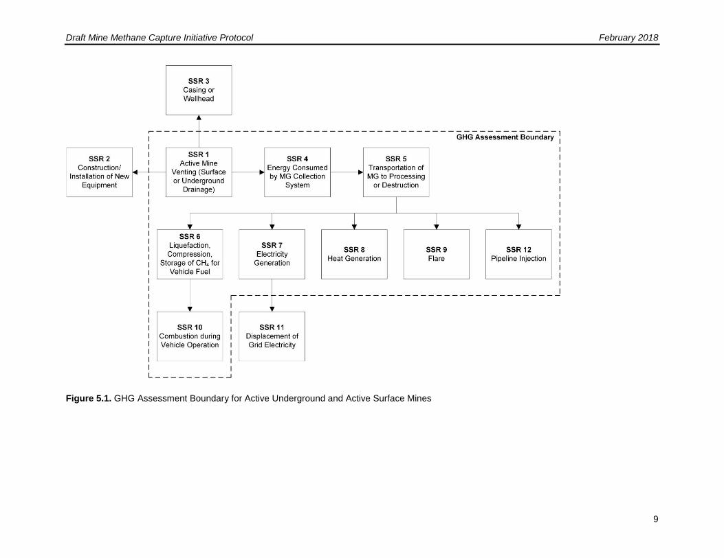
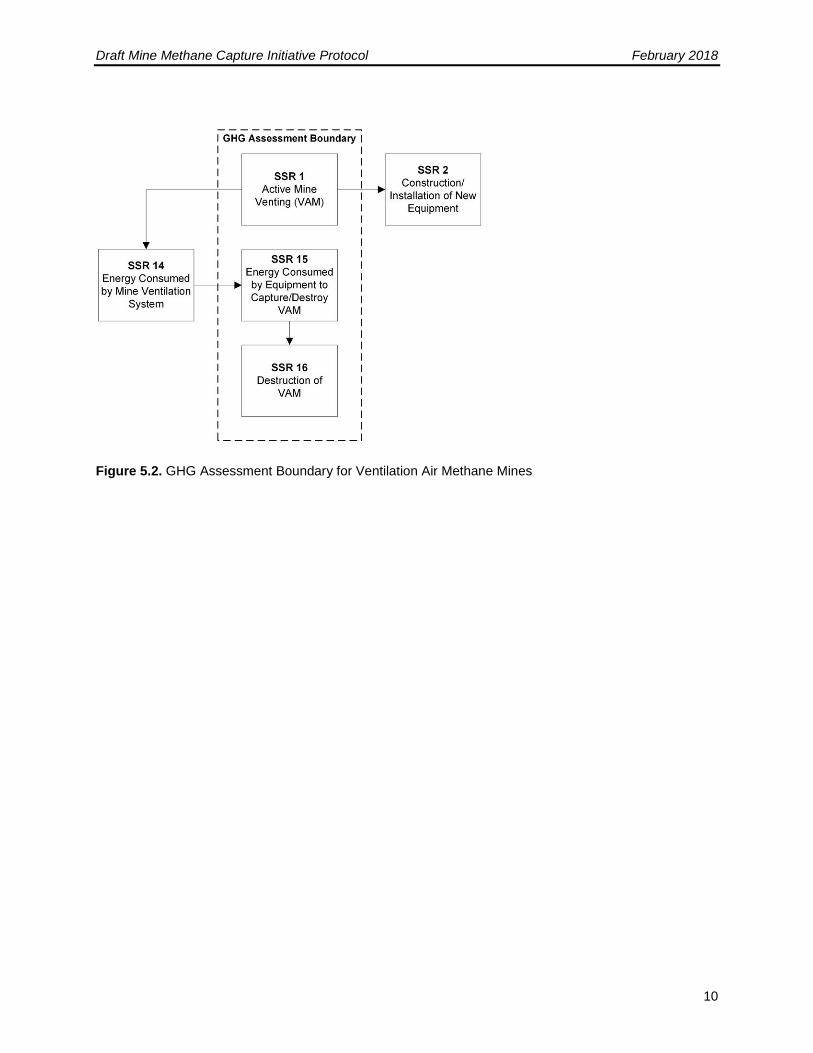
5 GHG Assessment Boundary a) The following SSRs have been considered in determining the GHG Assessment Boundary
1. Figure 5.1 illustrates all relevant GHG SSRs associated with drainage initiative activities and delineates the GHG Assessment Boundary.
2. Figure 5.2 illustrates all relevant GHG SSRs associated with ventilation air methane
(VAM) initiative activities and delineates the GHG Assessment Boundary. 3. Table 5.1 provides greater detail on each SSR and justification for the inclusion or
exclusion of certain SSRs and gases from the GHG Assessment Boundary.
Draft Mine Methane Capture Initiative Protocol February 2018
9
Figure 5.1. GHG Assessment Boundary for Active Underground and Active Surface Mines
Draft Mine Methane Capture Initiative Protocol February 2018
10
Figure 5.2. GHG Assessment Boundary for Ventilation Air Methane Mines
Draft Mine Methane Capture Initiative Protocol February 2018
11
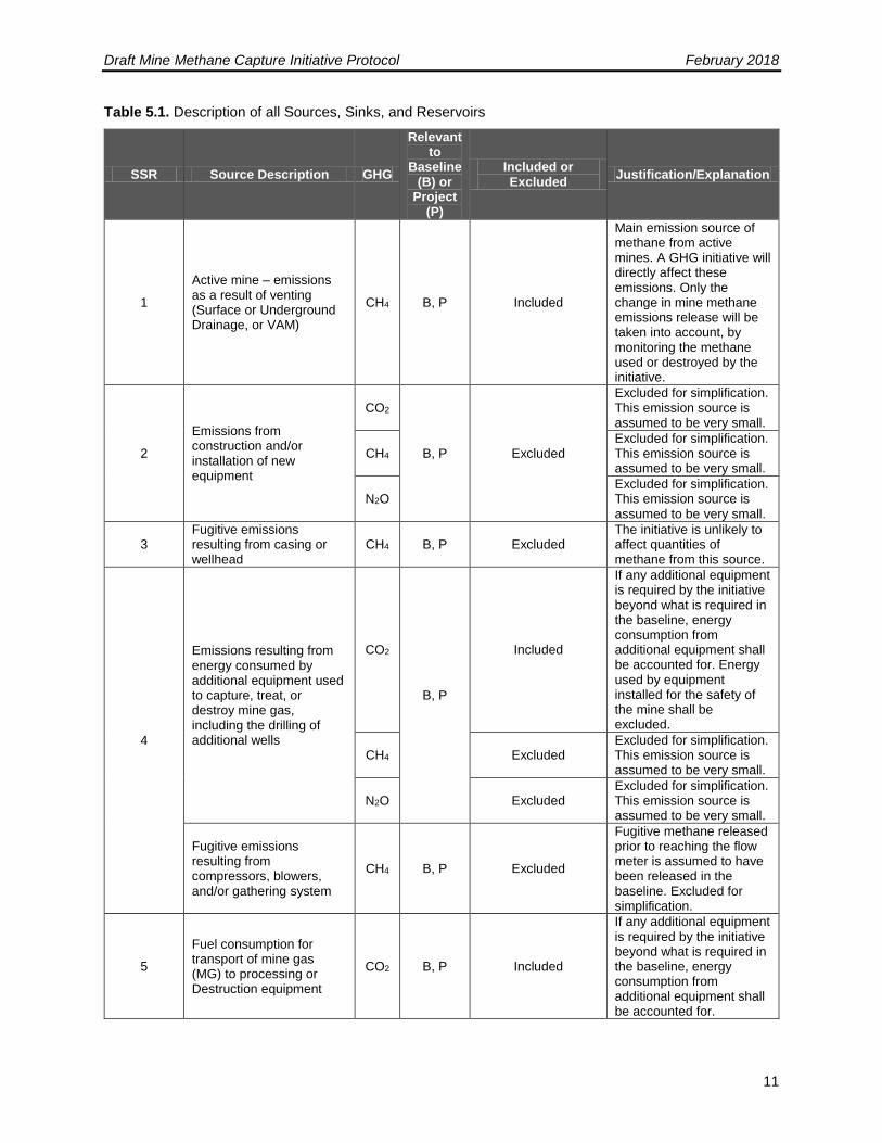
Table 5.1. Description of all Sources, Sinks, and Reservoirs
SSR Source Description GHG
Relevant to
Baseline (B) or
Project (P)
Included or Excluded
Justification/Explanation
1
Active mine – emissions as a result of venting (Surface or Underground Drainage, or VAM)
CH4 B, P Included
Main emission source of methane from active mines. A GHG initiative will directly affect these emissions. Only the change in mine methane emissions release will be taken into account, by monitoring the methane used or destroyed by the initiative.
2
Emissions from construction and/or installation of new equipment
CO2
B, P Excluded
Excluded for simplification. This emission source is assumed to be very small.
CH4 Excluded for simplification. This emission source is assumed to be very small.
N2O Excluded for simplification. This emission source is assumed to be very small.
3 Fugitive emissions resulting from casing or wellhead
CH4 B, P Excluded The initiative is unlikely to affect quantities of methane from this source.
4
Emissions resulting from energy consumed by additional equipment used to capture, treat, or destroy mine gas, including the drilling of additional wells
CO2
B, P
Included
If any additional equipment is required by the initiative beyond what is required in the baseline, energy consumption from additional equipment shall be accounted for. Energy used by equipment installed for the safety of the mine shall be excluded.
CH4 Excluded Excluded for simplification. This emission source is assumed to be very small.
N2O Excluded Excluded for simplification. This emission source is assumed to be very small.
Fugitive emissions resulting from compressors, blowers, and/or gathering system
CH4 B, P Excluded
Fugitive methane released prior to reaching the flow meter is assumed to have been released in the baseline. Excluded for simplification.
5
Fuel consumption for transport of mine gas (MG) to processing or Destruction equipment
CO2 B, P Included
If any additional equipment is required by the initiative beyond what is required in the baseline, energy consumption from additional equipment shall be accounted for.
Draft Mine Methane Capture Initiative Protocol February 2018
12
SSR Source Description GHG
Relevant to
Baseline (B) or
Project (P)
Included or Excluded
Justification/Explanation
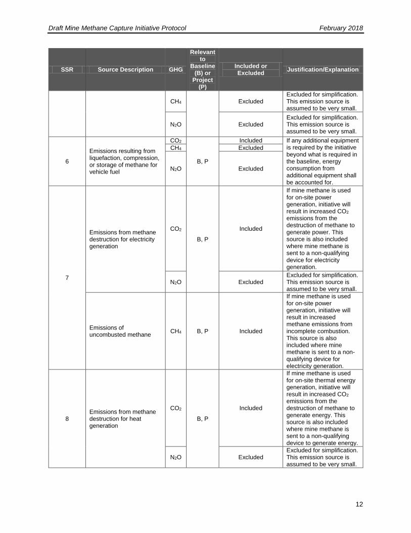
CH4 Excluded Excluded for simplification. This emission source is assumed to be very small.
N2O Excluded Excluded for simplification. This emission source is assumed to be very small.
6
Emissions resulting from liquefaction, compression, or storage of methane for vehicle fuel
CO2
B, P
Included If any additional equipment is required by the initiative beyond what is required in the baseline, energy consumption from additional equipment shall be accounted for.
CH4 Excluded
N2O Excluded
7
Emissions from methane destruction for electricity generation
CO2
B, P
Included
If mine methane is used for on-site power generation, initiative will result in increased CO2 emissions from the destruction of methane to generate power. This source is also included where mine methane is sent to a non-qualifying device for electricity generation.
N2O Excluded Excluded for simplification. This emission source is assumed to be very small.
Emissions of uncombusted methane
CH4 B, P Included
If mine methane is used for on-site power generation, initiative will result in increased methane emissions from incomplete combustion. This source is also included where mine methane is sent to a non-qualifying device for electricity generation.
8 Emissions from methane destruction for heat generation
CO2
B, P
Included
If mine methane is used for on-site thermal energy generation, initiative will result in increased CO2 emissions from the destruction of methane to generate energy. This source is also included where mine methane is sent to a non-qualifying device to generate energy.
N2O Excluded Excluded for simplification. This emission source is assumed to be very small.
Draft Mine Methane Capture Initiative Protocol February 2018
13
SSR Source Description GHG
Relevant to
Baseline (B) or
Project (P)
Included or Excluded
Justification/Explanation
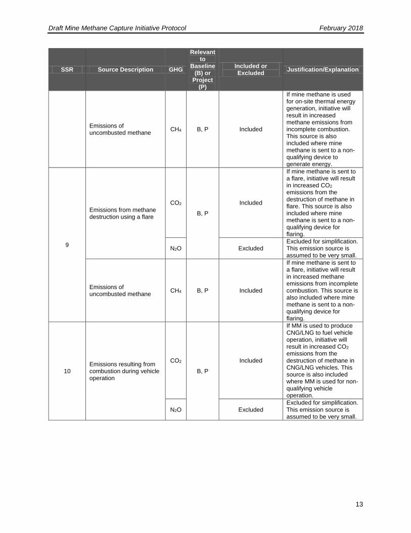
Emissions of uncombusted methane
CH4 B, P Included
If mine methane is used for on-site thermal energy generation, initiative will result in increased methane emissions from incomplete combustion. This source is also included where mine methane is sent to a non-qualifying device to generate energy.
9
Emissions from methane destruction using a flare
CO2
B, P
Included
If mine methane is sent to a flare, initiative will result in increased CO2 emissions from the destruction of methane in flare. This source is also included where mine methane is sent to a non-qualifying device for flaring.
N2O Excluded Excluded for simplification. This emission source is assumed to be very small.
Emissions of uncombusted methane
CH4 B, P Included
If mine methane is sent to a flare, initiative will result in increased methane emissions from incomplete combustion. This source is also included where mine methane is sent to a non-qualifying device for flaring.
10 Emissions resulting from combustion during vehicle operation
CO2
B, P
Included
If MM is used to produce CNG/LNG to fuel vehicle operation, initiative will result in increased CO2 emissions from the destruction of methane in CNG/LNG vehicles. This source is also included where MM is used for non-qualifying vehicle operation.
N2O Excluded Excluded for simplification. This emission source is assumed to be very small.
Draft Mine Methane Capture Initiative Protocol February 2018
14
SSR Source Description GHG
Relevant to
Baseline (B) or
Project (P)
Included or Excluded
Justification/Explanation
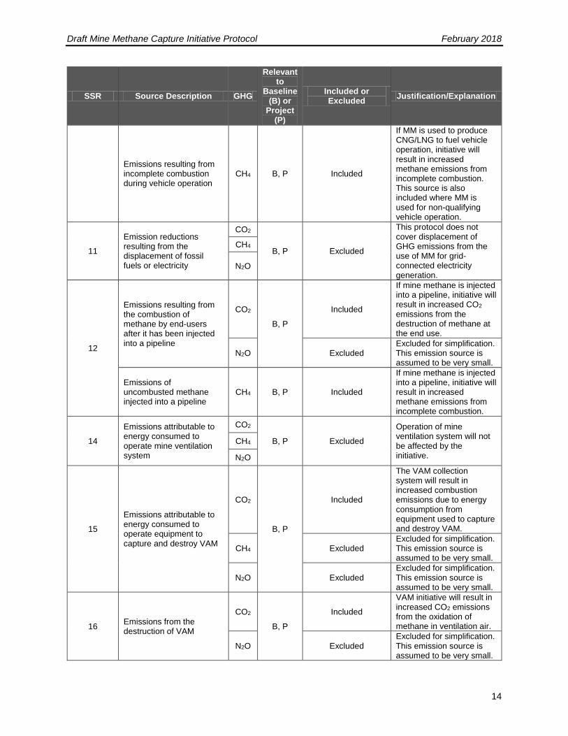
Emissions resulting from incomplete combustion during vehicle operation
CH4 B, P Included
If MM is used to produce CNG/LNG to fuel vehicle operation, initiative will result in increased methane emissions from incomplete combustion. This source is also included where MM is used for non-qualifying vehicle operation.
11
Emission reductions resulting from the displacement of fossil fuels or electricity
CO2
B, P Excluded
This protocol does not cover displacement of GHG emissions from the use of MM for grid-connected electricity generation.
CH4
N2O
12
Emissions resulting from the combustion of methane by end-users after it has been injected into a pipeline
CO2
B, P
Included
If mine methane is injected into a pipeline, initiative will result in increased CO2 emissions from the destruction of methane at the end use.
N2O Excluded Excluded for simplification. This emission source is assumed to be very small.
Emissions of uncombusted methane injected into a pipeline
CH4 B, P Included
If mine methane is injected into a pipeline, initiative will result in increased methane emissions from incomplete combustion.
14
Emissions attributable to energy consumed to operate mine ventilation system
CO2
B, P Excluded
Operation of mine ventilation system will not be affected by the initiative.
CH4
N2O
15
Emissions attributable to energy consumed to operate equipment to capture and destroy VAM
CO2
B, P
Included
The VAM collection system will result in increased combustion emissions due to energy consumption from equipment used to capture and destroy VAM.
CH4 Excluded Excluded for simplification. This emission source is assumed to be very small.
N2O Excluded Excluded for simplification. This emission source is assumed to be very small.
16 Emissions from the destruction of VAM
CO2
B, P
Included
VAM initiative will result in increased CO2 emissions from the oxidation of methane in ventilation air.
N2O Excluded Excluded for simplification. This emission source is assumed to be very small.
Draft Mine Methane Capture Initiative Protocol February 2018
15
SSR Source Description GHG
Relevant to
Baseline (B) or
Project (P)
Included or Excluded
Justification/Explanation
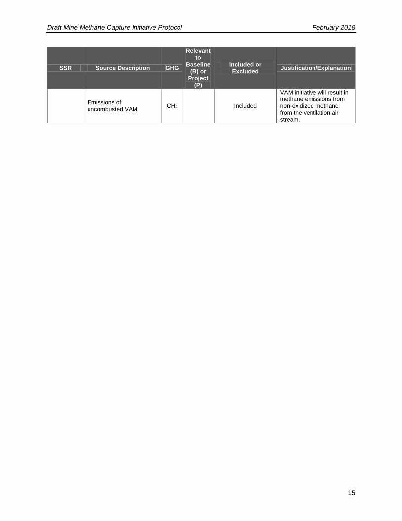
Emissions of uncombusted VAM
CH4 Included
VAM initiative will result in methane emissions from non-oxidized methane from the ventilation air stream.
Draft Mine Methane Capture Initiative Protocol February 2018
16
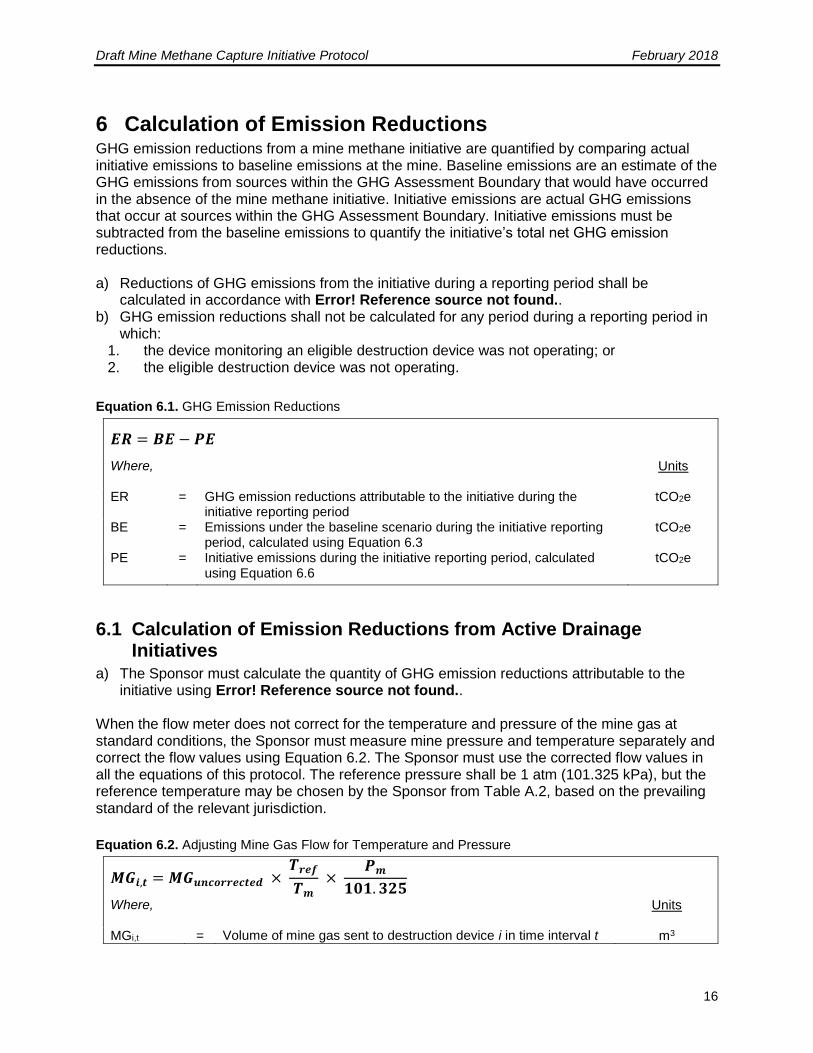
6 Calculation of Emission Reductions GHG emission reductions from a mine methane initiative are quantified by comparing actual initiative emissions to baseline emissions at the mine. Baseline emissions are an estimate of the GHG emissions from sources within the GHG Assessment Boundary that would have occurred in the absence of the mine methane initiative. Initiative emissions are actual GHG emissions that occur at sources within the GHG Assessment Boundary. Initiative emissions must be subtracted from the baseline emissions to quantify the initiative’s total net GHG emission reductions. a) Reductions of GHG emissions from the initiative during a reporting period shall be
calculated in accordance with Error! Reference source not found.. b) GHG emission reductions shall not be calculated for any period during a reporting period in
which: 1. the device monitoring an eligible destruction device was not operating; or 2. the eligible destruction device was not operating.
Equation 6.1. GHG Emission Reductions
𝑬𝑹 = 𝑩𝑬 − 𝑷𝑬
Where,
Units
ER = GHG emission reductions attributable to the initiative during the initiative reporting period
tCO2e
BE = Emissions under the baseline scenario during the initiative reporting period, calculated using Equation 6.3
tCO2e
PE = Initiative emissions during the initiative reporting period, calculated using Equation 6.6
tCO2e
6.1 Calculation of Emission Reductions from Active Drainage Initiatives
a) The Sponsor must calculate the quantity of GHG emission reductions attributable to the initiative using Error! Reference source not found..
When the flow meter does not correct for the temperature and pressure of the mine gas at standard conditions, the Sponsor must measure mine pressure and temperature separately and correct the flow values using Equation 6.2. The Sponsor must use the corrected flow values in all the equations of this protocol. The reference pressure shall be 1 atm (101.325 kPa), but the reference temperature may be chosen by the Sponsor from Table A.2, based on the prevailing standard of the relevant jurisdiction.
Equation 6.2. Adjusting Mine Gas Flow for Temperature and Pressure
𝑴𝑮𝒊,𝒕 = 𝑴𝑮𝒖𝒏𝒄𝒐𝒓𝒓𝒆𝒄𝒕𝒆𝒅 × 𝑻𝒓𝒆𝒇
𝑻𝒎 ×
𝑷𝒎
𝟏𝟎𝟏. 𝟑𝟐𝟓
Where,
Units
MGi,t = Volume of mine gas sent to destruction device i in time interval t m3
Draft Mine Methane Capture Initiative Protocol February 2018
17
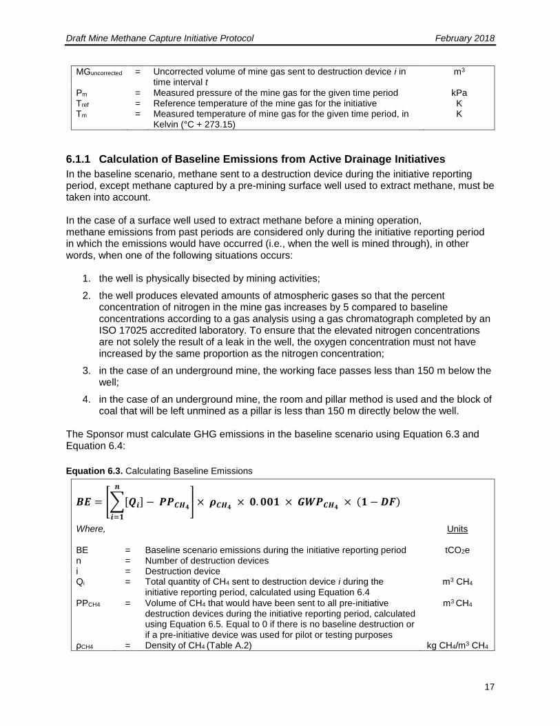
MGuncorrected = Uncorrected volume of mine gas sent to destruction device i in time interval t
m3
Pm = Measured pressure of the mine gas for the given time period kPa Tref = Reference temperature of the mine gas for the initiative K Tm = Measured temperature of mine gas for the given time period, in
Kelvin (°C + 273.15) K
6.1.1 Calculation of Baseline Emissions from Active Drainage Initiatives
In the baseline scenario, methane sent to a destruction device during the initiative reporting period, except methane captured by a pre-mining surface well used to extract methane, must be taken into account. In the case of a surface well used to extract methane before a mining operation, methane emissions from past periods are considered only during the initiative reporting period in which the emissions would have occurred (i.e., when the well is mined through), in other words, when one of the following situations occurs:
1. the well is physically bisected by mining activities;
2. the well produces elevated amounts of atmospheric gases so that the percent concentration of nitrogen in the mine gas increases by 5 compared to baseline concentrations according to a gas analysis using a gas chromatograph completed by an ISO 17025 accredited laboratory. To ensure that the elevated nitrogen concentrations are not solely the result of a leak in the well, the oxygen concentration must not have increased by the same proportion as the nitrogen concentration;
3. in the case of an underground mine, the working face passes less than 150 m below the well;
4. in the case of an underground mine, the room and pillar method is used and the block of coal that will be left unmined as a pillar is less than 150 m directly below the well.
The Sponsor must calculate GHG emissions in the baseline scenario using Equation 6.3 and Equation 6.4:
Equation 6.3. Calculating Baseline Emissions
𝑩𝑬 = [∑[𝑸𝒊] − 𝑷𝑷𝑪𝑯𝟒
𝒏
𝒊=𝟏
] × 𝝆𝑪𝑯𝟒 × 𝟎. 𝟎𝟎𝟏 × 𝑮𝑾𝑷𝑪𝑯𝟒
× (𝟏 − 𝑫𝑭)
Where,
Units
BE = Baseline scenario emissions during the initiative reporting period tCO2e n = Number of destruction devices i = Destruction device Qi = Total quantity of CH4 sent to destruction device i during the
initiative reporting period, calculated using Equation 6.4 m3 CH4
PPCH4 = Volume of CH4 that would have been sent to all pre-initiative destruction devices during the initiative reporting period, calculated using Equation 6.5. Equal to 0 if there is no baseline destruction or if a pre-initiative device was used for pilot or testing purposes
m3 CH4
ρCH4 = Density of CH4 (Table A.2) kg CH4/m3 CH4

Draft Mine Methane Capture Initiative Protocol February 2018
18
0.001 = Conversion factor, kilograms to tonnes tCH4/kg CH4 GWPCH4 = Global Warming Potential factor of CH4, as set out in O.Reg.
143/16 concerning the reporting of GHG emissions tCO2e/tCH4
DF = Discount factor to account for uncertainties associated with the monitoring equipment for CH4 content in the mine gas, namely a factor of 0 when the CH4 content in the mine gas is measured continuously, and 0.1 in other cases, with measurements made at least weekly
Equation 6.4. Baseline Methane Released to Atmosphere
𝑸𝒊 = ∑[𝑴𝑮𝒊,𝒕 × 𝑪𝑪𝑯𝟒,𝒕]
𝒏
𝒕=𝟏
Where,
Units
Qi = Total quantity of CH4 sent to destruction device i during the initiative reporting period
m3 CH4
n = Number of time intervals during the initiative reporting period
t = Time interval shown in Table 7.1 for which CH4 flow and content measurements for the mine gas are aggregated
MGi,t = Volume of mine gas sent to destruction device i in time interval t, except mine gas from a surface well that is not yet mined through. Despite the foregoing, if the surface well is mined through during the initiative reporting period, the mine gas sent to a destruction device during the current reporting period and in previous years must be included
m3
CCH4,t = Average CH4 content in the mine gas sent to a destruction device during time interval t
m3 CH4/ m3 MG
For initiatives utilizing one or more pre-initiative destruction device, baseline emissions from that pre-initiative destruction device must be calculated using Equation 6.5. The volume of mine gas sent to pre-initiative destruction device(s) (MGPP,i,t) must be estimated every reporting period. For pre-initiative destruction devices, this volume may be estimated as the full capacity of the pre-initiative destruction device(s). Pre-initiative devices that are not in place as of the initiative start date may alternatively choose to calculate this volume of mine gas sent to the pre-initiative destruction device(s) in a baseline monitoring period. This baseline monitoring period must take place prior to the initiative start date for a period of at least 90 consecutive days and must follow the same monitoring requirements as outlined in Section 7.2 for MGi,t.
Draft Mine Methane Capture Initiative Protocol February 2018
19
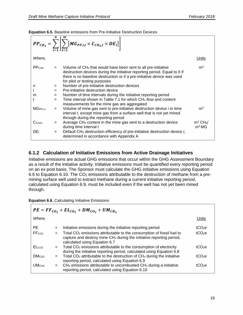
Equation 6.5. Baseline emissions from Pre-Initiative Destruction Devices
𝑷𝑷𝑪𝑯𝟒= ∑ [∑[𝑴𝑮𝑷𝑷,𝒊,𝒕 × 𝑪𝑪𝑯𝟒,𝒕 × 𝑫𝑬𝒊]
𝒎
𝒕=𝟏
]
𝒏
𝒊=𝟏
Where,
Units
PPCH4 = Volume of CH4 that would have been sent to all pre-initiative destruction devices during the initiative reporting period. Equal to 0 if there is no baseline destruction or if a pre-initiative device was used for pilot or testing purposes
m3
n = Number of pre-initiative destruction devices i = Pre-initiative destruction device m = Number of time intervals during the initiative reporting period t = Time interval shown in Table 7.1 for which CH4 flow and content
measurements for the mine gas are aggregated
MGPP,i,t = Volume of mine gas sent to pre-initiative destruction device i in time interval t, except mine gas from a surface well that is not yet mined through during the reporting period
m3
CCH4,t = Average CH4 content in the mine gas sent to a destruction device during time interval t
m3 CH4/ m3 MG
DEi = Default CH4 destruction efficiency of pre-initiative destruction device i, determined in accordance with Appendix A
6.1.2 Calculation of Initiative Emissions from Active Drainage Initiatives
Initiative emissions are actual GHG emissions that occur within the GHG Assessment Boundary as a result of the initiative activity. Initiative emissions must be quantified every reporting period on an ex post basis. The Sponsor must calculate the GHG initiative emissions using Equation 6.6 to Equation 6.10. The CO2 emissions attributable to the destruction of methane from a pre-mining surface well used to extract methane during a current initiative reporting period, calculated using Equation 6.9, must be included even if the well has not yet been mined through.
Equation 6.6. Calculating Initiative Emissions
𝑷𝑬 = 𝑭𝑭𝑪𝑶𝟐+ 𝑬𝑳𝑪𝑶𝟐
+ 𝑫𝑴𝑪𝑶𝟐+ 𝑼𝑴𝑪𝑯𝟒
Where,
Units
PE = Initiative emissions during the initiative reporting period tCO2e
FFCO2 = Total CO2 emissions attributable to the consumption of fossil fuel to capture and destroy mine CH4 during the initiative reporting period, calculated using Equation 6.7
tCO2e
ELCO2 = Total CO2 emissions attributable to the consumption of electricity during the initiative reporting period, calculated using Equation 6.8
tCO2e
DMCO2 = Total CO2 attributable to the destruction of CH4 during the initiative reporting period, calculated using Equation 6.9
tCO2e
UMCH4 = CH4 emissions attributable to uncombusted CH4 during a initiative reporting period, calculated using Equation 6.10
tCO2e
Draft Mine Methane Capture Initiative Protocol February 2018
20
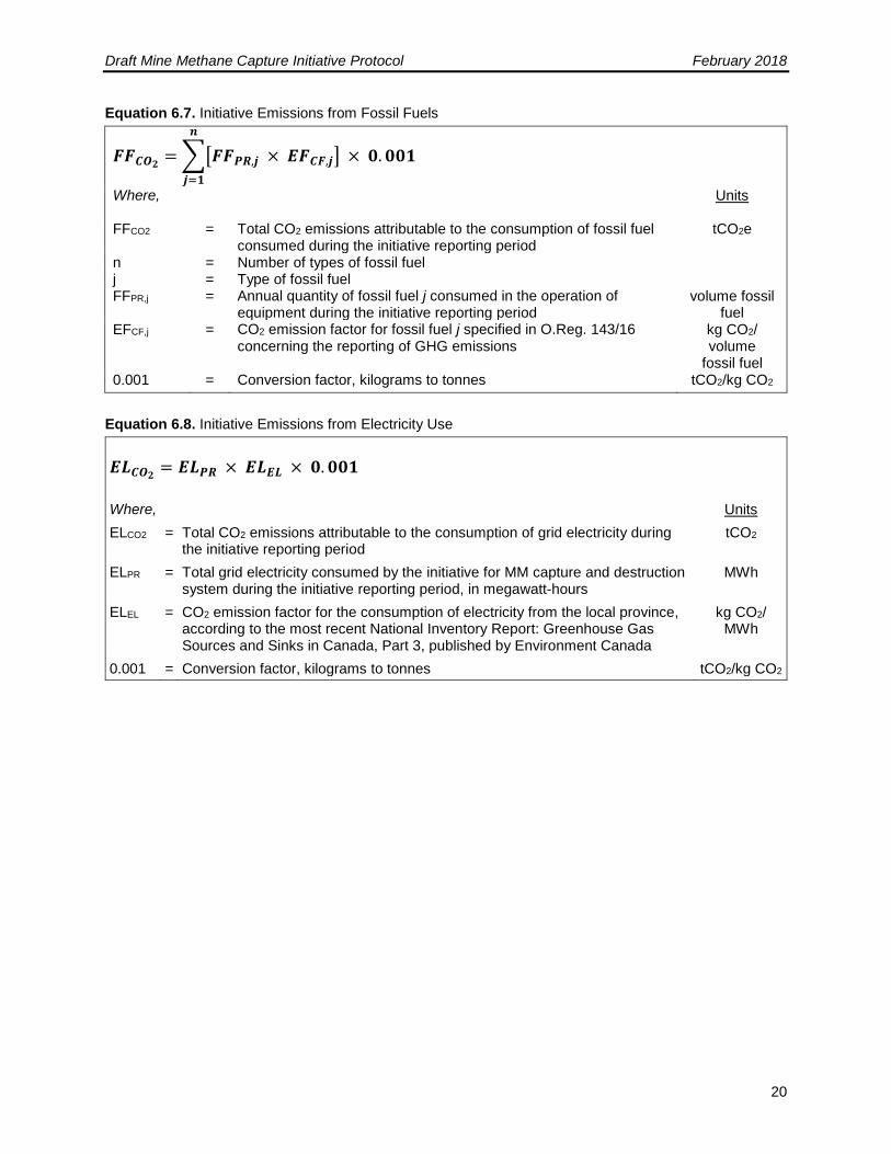
Equation 6.7. Initiative Emissions from Fossil Fuels
𝑭𝑭𝑪𝑶𝟐= ∑[𝑭𝑭𝑷𝑹,𝒋 × 𝑬𝑭𝑪𝑭,𝒋]
𝒏
𝒋=𝟏
× 𝟎. 𝟎𝟎𝟏
Where,
Units
FFCO2 = Total CO2 emissions attributable to the consumption of fossil fuel consumed during the initiative reporting period
tCO2e
n = Number of types of fossil fuel j = Type of fossil fuel FFPR,j = Annual quantity of fossil fuel j consumed in the operation of
equipment during the initiative reporting period volume fossil
fuel EFCF,j = CO2 emission factor for fossil fuel j specified in O.Reg. 143/16
concerning the reporting of GHG emissions kg CO2/ volume
fossil fuel 0.001 = Conversion factor, kilograms to tonnes tCO2/kg CO2
Equation 6.8. Initiative Emissions from Electricity Use
𝑬𝑳𝑪𝑶𝟐= 𝑬𝑳𝑷𝑹 × 𝑬𝑳𝑬𝑳 × 𝟎. 𝟎𝟎𝟏
Where, Units
ELCO2 = Total CO2 emissions attributable to the consumption of grid electricity during the initiative reporting period
tCO2
ELPR = Total grid electricity consumed by the initiative for MM capture and destruction system during the initiative reporting period, in megawatt-hours
MWh
ELEL = CO2 emission factor for the consumption of electricity from the local province, according to the most recent National Inventory Report: Greenhouse Gas Sources and Sinks in Canada, Part 3, published by Environment Canada
kg CO2/ MWh
0.001 = Conversion factor, kilograms to tonnes tCO2/kg CO2
Draft Mine Methane Capture Initiative Protocol February 2018
21
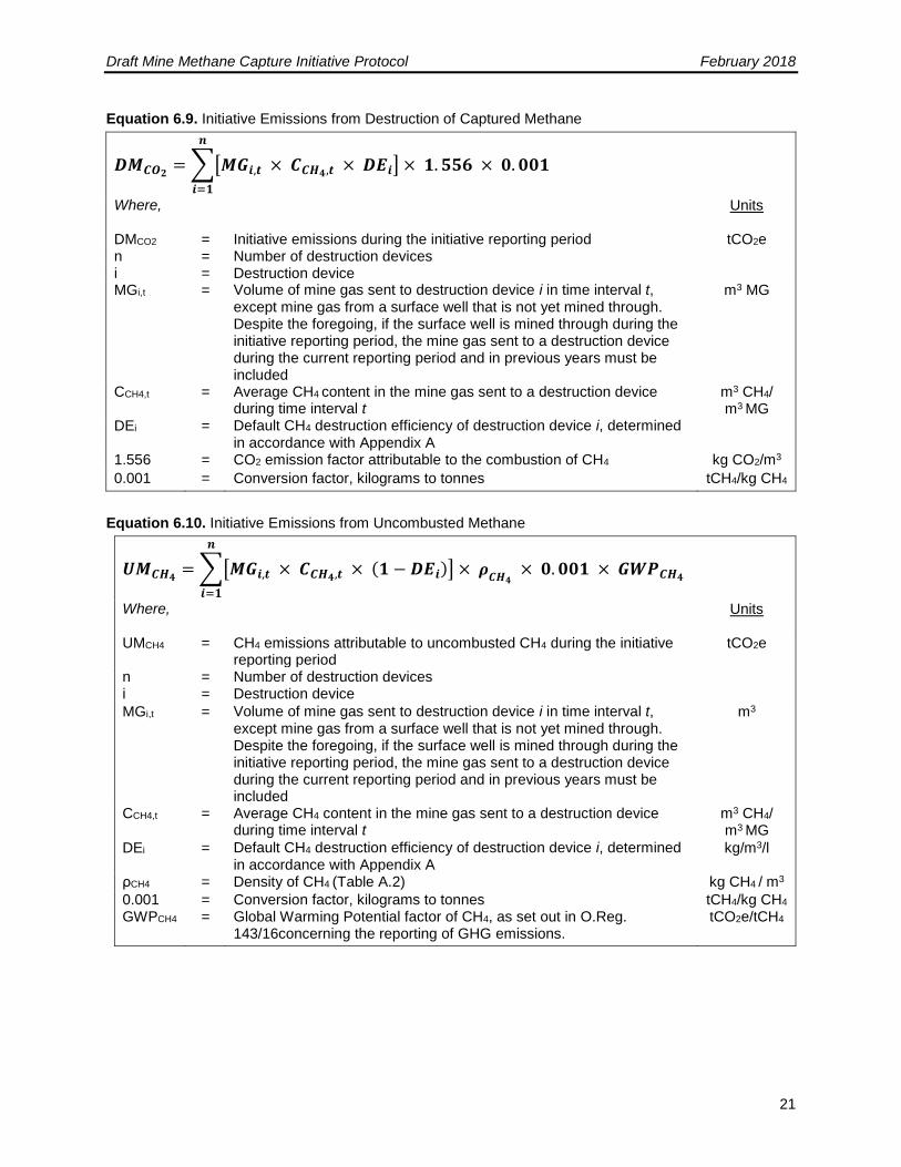
Equation 6.9. Initiative Emissions from Destruction of Captured Methane
𝑫𝑴𝑪𝑶𝟐= ∑[𝑴𝑮𝒊,𝒕 × 𝑪𝑪𝑯𝟒,𝒕 × 𝑫𝑬𝒊]
𝒏
𝒊=𝟏
× 𝟏. 𝟓𝟓𝟔 × 𝟎. 𝟎𝟎𝟏
Where,
Units
DMCO2 = Initiative emissions during the initiative reporting period tCO2e n = Number of destruction devices i = Destruction device MGi,t = Volume of mine gas sent to destruction device i in time interval t,
except mine gas from a surface well that is not yet mined through. Despite the foregoing, if the surface well is mined through during the initiative reporting period, the mine gas sent to a destruction device during the current reporting period and in previous years must be included
m3 MG
CCH4,t = Average CH4 content in the mine gas sent to a destruction device during time interval t
m3 CH4/ m3 MG
DEi = Default CH4 destruction efficiency of destruction device i, determined in accordance with Appendix A
1.556 = CO2 emission factor attributable to the combustion of CH4 kg CO2/m3
0.001 = Conversion factor, kilograms to tonnes tCH4/kg CH4
Equation 6.10. Initiative Emissions from Uncombusted Methane
𝑼𝑴𝑪𝑯𝟒= ∑[𝑴𝑮𝒊,𝒕 × 𝑪𝑪𝑯𝟒,𝒕 × (𝟏 − 𝑫𝑬𝒊)]
𝒏
𝒊=𝟏
× 𝝆𝑪𝑯𝟒
× 𝟎. 𝟎𝟎𝟏 × 𝑮𝑾𝑷𝑪𝑯𝟒
Where,
Units
UMCH4 = CH4 emissions attributable to uncombusted CH4 during the initiative reporting period
tCO2e
n = Number of destruction devices i = Destruction device
MGi,t = Volume of mine gas sent to destruction device i in time interval t, except mine gas from a surface well that is not yet mined through. Despite the foregoing, if the surface well is mined through during the initiative reporting period, the mine gas sent to a destruction device during the current reporting period and in previous years must be included
m3
CCH4,t = Average CH4 content in the mine gas sent to a destruction device during time interval t
m3 CH4/ m3 MG
DEi = Default CH4 destruction efficiency of destruction device i, determined in accordance with Appendix A
kg/m3/l
ρCH4 = Density of CH4 (Table A.2) kg CH4 / m3
0.001 = Conversion factor, kilograms to tonnes tCH4/kg CH4 GWPCH4 = Global Warming Potential factor of CH4, as set out in O.Reg.
143/16concerning the reporting of GHG emissions. tCO2e/tCH4

Draft Mine Methane Capture Initiative Protocol February 2018
22
6.2 Calculation of Emission Reductions from Ventilation Air Methane Initiatives
a) The Sponsor must calculate the quantity of GHG emission reductions attributable to the initiative using Equation 6.11.
Equation 6.11. GHG Emission Reductions
𝑬𝑹 = 𝑩𝑬 − 𝑷𝑬
Where,
Units
ER = GHG emission reductions attributable to the initiative during the initiative reporting period
tCO2e
BE = Emissions under the baseline scenario during the initiative reporting period, calculated using Equation 6.12
tCO2e
PE = Initiative emissions during the initiative reporting period, calculated using Equation 6.13
tCO2e
6.2.1 Calculation of Baseline Emissions from Ventilation Air Methane Initiatives
The Sponsor must calculate GHG emissions in the baseline scenario using Equation 6.12.
Equation 6.12. Calculating Baseline Methane Emissions
𝑩𝑬 = ∑[(𝑽𝑨𝒊𝒏,𝒕 − 𝑽𝑨𝑷𝑷) × 𝑪𝑪𝑯𝟒,𝒕] × 𝝆𝑪𝑯𝟒
× 𝟎. 𝟎𝟎𝟏 × 𝑮𝑾𝑷𝑪𝑯𝟒
𝒏
𝒕=𝟏
Where,
Units
BE = Baseline scenario emissions during the initiative reporting period tCO2e n = Number of time intervals during the initiative reporting period t = Time interval shown in Table 7.1 for which flow and content
measurements of ventilation air CH4 are aggregated
VAin,t = Volume of ventilation air sent to destruction device during time interval t m3 VAPP = Volume of ventilation air that would have been sent to pre-initiative
destruction device, during time interval t. Equal to 0 if there is no baseline destruction
m3
CCH4,t = Average CH4 content in ventilation air before entering destruction device during time interval t
m3 CH4/m3
ρCH4 = Density of CH4 (Table A.2) kg CH4/m3
0.001 = Conversion factor, kilograms to tonnes tCH4/kg CH4 GWPCH4 = Global Warming Potential factor of CH4, as set out in concerning the
reporting of GHG emissions tCO2e/tCH4
The volume of ventilation air sent to all pre-initiative destruction device(s) (VAPP) must be estimated every reporting period. For pre-initiative destruction devices, this volume may be estimated as the full capacity of the pre-initiative destruction device(s). Pre-initiative devices that are not in place as of the initiative start date may alternatively choose to estimate this volume of ventilation air sent to the pre-initiative destruction device(s) in a baseline monitoring period. This baseline monitoring period must take place prior to the initiative start date for a period of at least 90 consecutive days and must follow the same monitoring requirements as outlined in Section 7.2 for VAin,t.
Draft Mine Methane Capture Initiative Protocol February 2018
23
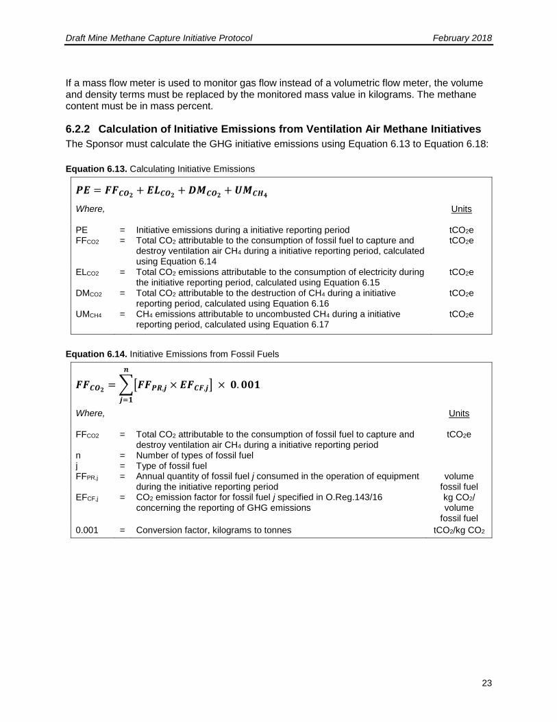
If a mass flow meter is used to monitor gas flow instead of a volumetric flow meter, the volume and density terms must be replaced by the monitored mass value in kilograms. The methane content must be in mass percent.
6.2.2 Calculation of Initiative Emissions from Ventilation Air Methane Initiatives
The Sponsor must calculate the GHG initiative emissions using Equation 6.13 to Equation 6.18:
Equation 6.13. Calculating Initiative Emissions
𝑷𝑬 = 𝑭𝑭𝑪𝑶𝟐+ 𝑬𝑳𝑪𝑶𝟐
+ 𝑫𝑴𝑪𝑶𝟐+ 𝑼𝑴𝑪𝑯𝟒
Where,
Units
PE = Initiative emissions during a initiative reporting period tCO2e FFCO2 = Total CO2 attributable to the consumption of fossil fuel to capture and
destroy ventilation air CH4 during a initiative reporting period, calculated using Equation 6.14
tCO2e
ELCO2 = Total CO2 emissions attributable to the consumption of electricity during the initiative reporting period, calculated using Equation 6.15
tCO2e
DMCO2 = Total CO2 attributable to the destruction of CH4 during a initiative reporting period, calculated using Equation 6.16
tCO2e
UMCH4 = CH4 emissions attributable to uncombusted CH4 during a initiative reporting period, calculated using Equation 6.17
tCO2e
Equation 6.14. Initiative Emissions from Fossil Fuels
𝑭𝑭𝑪𝑶𝟐= ∑[𝑭𝑭𝑷𝑹,𝒋 × 𝑬𝑭𝑪𝑭,𝒋]
𝒏
𝒋=𝟏
× 𝟎. 𝟎𝟎𝟏
Where,
Units
FFCO2 = Total CO2 attributable to the consumption of fossil fuel to capture and destroy ventilation air CH4 during a initiative reporting period
tCO2e
n = Number of types of fossil fuel j = Type of fossil fuel FFPR,j = Annual quantity of fossil fuel j consumed in the operation of equipment
during the initiative reporting period volume
fossil fuel EFCF,j = CO2 emission factor for fossil fuel j specified in O.Reg.143/16
concerning the reporting of GHG emissions kg CO2/ volume
fossil fuel
0.001 = Conversion factor, kilograms to tonnes tCO2/kg CO2
Draft Mine Methane Capture Initiative Protocol February 2018
24
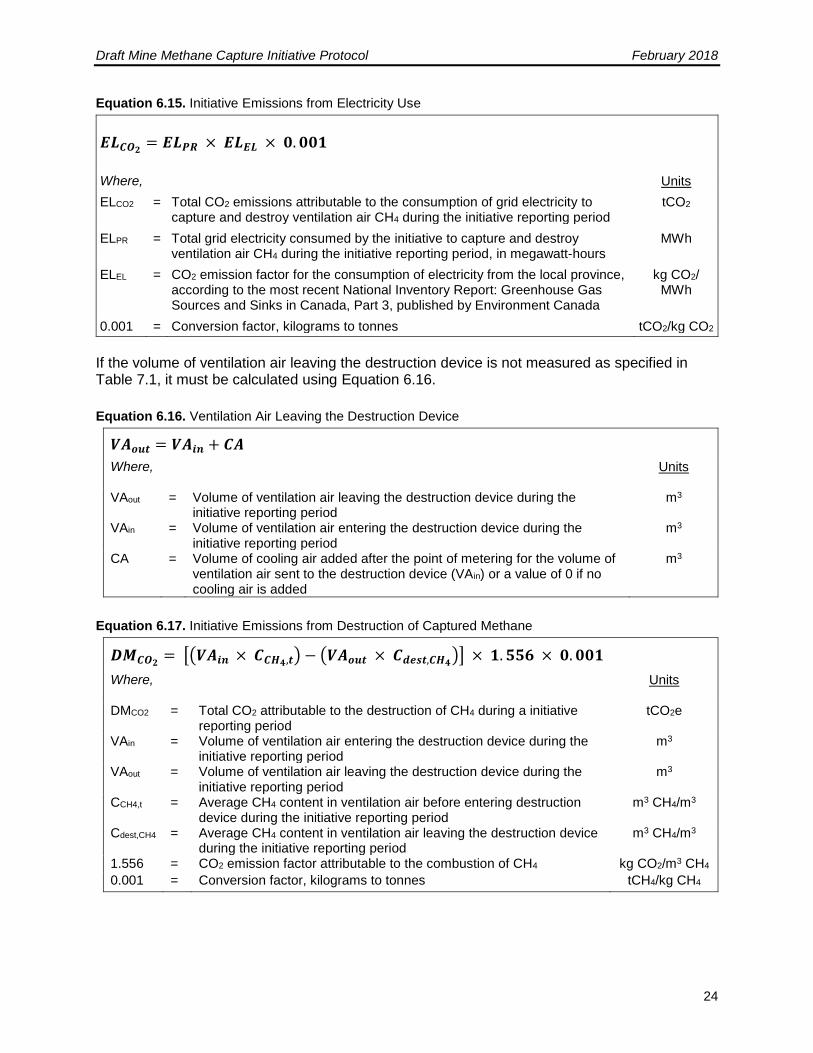
Equation 6.15. Initiative Emissions from Electricity Use
𝑬𝑳𝑪𝑶𝟐= 𝑬𝑳𝑷𝑹 × 𝑬𝑳𝑬𝑳 × 𝟎. 𝟎𝟎𝟏
Where, Units
ELCO2 = Total CO2 emissions attributable to the consumption of grid electricity to capture and destroy ventilation air CH4 during the initiative reporting period
tCO2
ELPR = Total grid electricity consumed by the initiative to capture and destroy ventilation air CH4 during the initiative reporting period, in megawatt-hours
MWh
ELEL = CO2 emission factor for the consumption of electricity from the local province, according to the most recent National Inventory Report: Greenhouse Gas Sources and Sinks in Canada, Part 3, published by Environment Canada
kg CO2/ MWh
0.001 = Conversion factor, kilograms to tonnes tCO2/kg CO2
If the volume of ventilation air leaving the destruction device is not measured as specified in Table 7.1, it must be calculated using Equation 6.16.
Equation 6.16. Ventilation Air Leaving the Destruction Device
𝑽𝑨𝒐𝒖𝒕 = 𝑽𝑨𝒊𝒏 + 𝑪𝑨
Where,
Units
VAout = Volume of ventilation air leaving the destruction device during the initiative reporting period
m3
VAin = Volume of ventilation air entering the destruction device during the initiative reporting period
m3
CA = Volume of cooling air added after the point of metering for the volume of ventilation air sent to the destruction device (VAin) or a value of 0 if no cooling air is added
m3
Equation 6.17. Initiative Emissions from Destruction of Captured Methane
𝑫𝑴𝑪𝑶𝟐= [(𝑽𝑨𝒊𝒏 × 𝑪𝑪𝑯𝟒,𝒕) − (𝑽𝑨𝒐𝒖𝒕 × 𝑪𝒅𝒆𝒔𝒕,𝑪𝑯𝟒
)] × 𝟏. 𝟓𝟓𝟔 × 𝟎. 𝟎𝟎𝟏
Where,
Units
DMCO2 = Total CO2 attributable to the destruction of CH4 during a initiative reporting period
tCO2e
VAin = Volume of ventilation air entering the destruction device during the initiative reporting period
m3
VAout = Volume of ventilation air leaving the destruction device during the initiative reporting period
m3
CCH4,t = Average CH4 content in ventilation air before entering destruction device during the initiative reporting period
m3 CH4/m3
Cdest,CH4 = Average CH4 content in ventilation air leaving the destruction device during the initiative reporting period
m3 CH4/m3
1.556 = CO2 emission factor attributable to the combustion of CH4 kg CO2/m3 CH4
0.001 = Conversion factor, kilograms to tonnes tCH4/kg CH4
Draft Mine Methane Capture Initiative Protocol February 2018
25
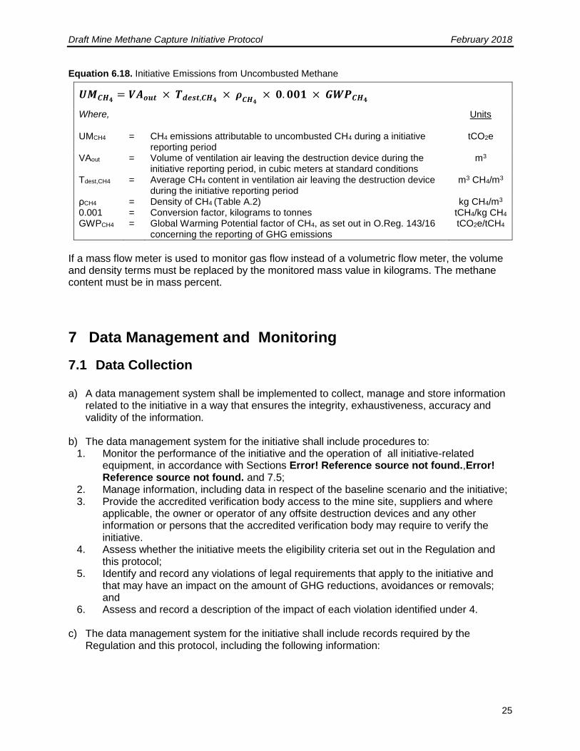
Equation 6.18. Initiative Emissions from Uncombusted Methane
𝑼𝑴𝑪𝑯𝟒= 𝑽𝑨𝒐𝒖𝒕 × 𝑻𝒅𝒆𝒔𝒕,𝑪𝑯𝟒
× 𝝆𝑪𝑯𝟒
× 𝟎. 𝟎𝟎𝟏 × 𝑮𝑾𝑷𝑪𝑯𝟒
Where,
Units
UMCH4 = CH4 emissions attributable to uncombusted CH4 during a initiative reporting period
tCO2e
VAout = Volume of ventilation air leaving the destruction device during the initiative reporting period, in cubic meters at standard conditions
m3
Tdest,CH4 = Average CH4 content in ventilation air leaving the destruction device during the initiative reporting period
m3 CH4/m3
ρCH4 = Density of CH4 (Table A.2) kg CH4/m3 0.001 = Conversion factor, kilograms to tonnes tCH4/kg CH4 GWPCH4 = Global Warming Potential factor of CH4, as set out in O.Reg. 143/16
concerning the reporting of GHG emissions tCO2e/tCH4
If a mass flow meter is used to monitor gas flow instead of a volumetric flow meter, the volume and density terms must be replaced by the monitored mass value in kilograms. The methane content must be in mass percent.
7 Data Management and Monitoring
7.1 Data Collection
a) A data management system shall be implemented to collect, manage and store information related to the initiative in a way that ensures the integrity, exhaustiveness, accuracy and validity of the information.
b) The data management system for the initiative shall include procedures to: 1. Monitor the performance of the initiative and the operation of all initiative-related
equipment, in accordance with Sections Error! Reference source not found.,Error! Reference source not found. and 7.5;
2. Manage information, including data in respect of the baseline scenario and the initiative; 3. Provide the accredited verification body access to the mine site, suppliers and where
applicable, the owner or operator of any offsite destruction devices and any other information or persons that the accredited verification body may require to verify the initiative.
4. Assess whether the initiative meets the eligibility criteria set out in the Regulation and this protocol;
5. Identify and record any violations of legal requirements that apply to the initiative and that may have an impact on the amount of GHG reductions, avoidances or removals; and
6. Assess and record a description of the impact of each violation identified under 4.
c) The data management system for the initiative shall include records required by the Regulation and this protocol, including the following information:
Draft Mine Methane Capture Initiative Protocol February 2018
26
1. All baseline scenario and initiative continuous monitoring devices shall record values every 15 minutes, except as set out in paragraph (1) below, and include the average at a minimum frequency of daily. i. Initiatives with continuous CH4 analyzers may record values at frequencies other
than every 15 minutes in accordance with the data acquisition system, and include the average at a minimum frequency of daily.
2. The value of Destbase shall be aggregated at a frequency of at least weekly, and the selected frequency shall be applied consistently throughout the reporting period.
3. All other baseline scenario monitoring devices shall record one measured value per day on the day the measurement was made.
4. All other monitoring devices shall record values and average those values at the frequencies set out in Section 7.5.
5. Documentation of the engineering design and flow characteristics of the MMC collection system.
7.2 Monitoring Requirements
7.2.1 General
a) Procedures shall be established and followed to accurately assess whether the initiative meets the applicable eligibility criteria set out in Section Error! Reference source not found..
b) All initiative-related equipment shall be operated in a manner consistent with the manufacturer’s specifications and in accordance with the Section 7 and the performance of the initiative shall be monitored in accordance with Section 7.5.
c) Electricity data may be measured using an on-site meter or determined using electricity purchasing records.
d) Fossil fuel use may be determined using monthly fossil fuel purchasing records. At a minimum, the monitoring plan must include the following:
1. Methods used to collect and record the data required for all the relevant parameters in Table 7.1;
2. Frequency of data acquisition;
3. Record keeping plan (see Section 10 for minimum record keeping requirements)
4. Frequency of instrument cleaning, inspection and calibration activities, and of the verification of instrument calibration accuracy;
5. The role and qualifications of the person responsible for each monitoring activity, as well as the quality assurance and quality control measures taken to ensure that data acquisition and instrument calibration are carried out consistently and with precision;
6. A detailed diagram of the mine methane capture and treatment or destruction system, including the location of existing and planned wells and boreholes and the placement of all measurement instruments and equipment that affect included SSRs; and
Sponsors are responsible for monitoring the performance of the initiative and ensuring that the operation of all initiative-related equipment is consistent with the manufacturer’s recommendations. For drainage initiatives, methane emission reductions from mine gas capture and control systems must be monitored with measurement equipment that directly meters:
Draft Mine Methane Capture Initiative Protocol February 2018
27
1. The flow of mine gas delivered to each destruction device2, measured continuously and
recorded every 15 minutes or totalized and recorded at least daily, adjusted for temperature and pressure; and
2. The fraction of methane in the mine gas delivered to each destruction device, measured continuously and recorded every 15 minutes and averaged at least daily (measurements taken at a frequency that is between daily and weekly may be used with the application of a 10% discount in Equation 6.3).
For VAM initiatives, the measurement equipment must directly meter:
1. The flow of ventilation air sent to each destruction device, measured continuously and recorded every 2 minutes and totalized hourly, adjusted for temperature and pressure; and
2. The fraction of methane in the ventilation air delivered to each destruction device, measured continuously and recorded every 2 minutes and totalized hourly.
All flow data collected must be corrected for temperature and pressure. Pressure correction is to 1 atm, but temperature correction may be chosen according to one of the values listed in Table A.2 and then applied to all gas measurement data for the initiative. The appropriate value for the density of methane is based on the chosen reference temperature. The temperature and pressure of the mine gas must be measured continuously. No separate monitoring of temperature and pressure is necessary when using flow meters that automatically correct for temperature and pressure, expressing mine gas volumes in normalized cubic meters. The continuous methane analyzer is the preferred option for monitoring methane concentrations, but Sponsors may take weekly methane concentration measurements for up to four consecutive weeks for drainage initiatives, if necessary. When using this alternative approach, Sponsors must account for the uncertainty associated with these weekly measurements by applying a 10% discount factor to the total quantity of methane collected and destroyed in Equation 6.3. Non-continuous methane measurement may occur through the use of a calibrated, portable methane analyzer, or a device that collects gas samples into a common container which is then analyzed by an off-site laboratory, providing an average methane content for the period. In the latter case, the device must collect samples at least weekly, and the gas analysis must be carried out at least monthly. Methane fraction of the mine gas to be measured on a wet/dry basis for drainage initiatives (must be measured on same basis as flow, temperature, and pressure). The methane analyzer and flow meter should be installed in the same relative placement to any moisture-removing components of the mine gas system (there should not be a moisture-removing component separating the measurement of flow and methane fraction). An acceptable variation to this arrangement would be in the case where the flow meter is placed after a moisture-removing component (dry basis), while the methane analyzer is placed before this component (wet basis). The opposite arrangement is not permissible. The operational activity of the mine gas or ventilation air collection system and destruction devices shall be monitored and recorded at least hourly to ensure actual mine gas destruction.
2 A single meter may be used for multiple, identical destruction devices. In this instance, methane destruction in these units will be eligible only if both units are monitored to be operational, unless evidence is available to document that the design of the device is such that methane may not pass through when it is not operational.
Draft Mine Methane Capture Initiative Protocol February 2018
28
GHG reductions will not be accounted for during periods in which the destruction device is not operational. For flares, operation is defined as thermocouple readings above 260°C, unless there is a higher regulatory standard for the relevant jurisdiction. For all other destruction devices, the means of demonstration shall be determined by the Sponsor, according to applicable regulatory standards, should they exist, and otherwise according to manufacturer guidance, and subject to verifier review. If the Sponsor can demonstrate that the engineering design of the destruction system is such that gas may not be released when the device is not operational, and that such design elements are functioning properly, it is not required to monitor operational status on an hourly basis.
7.2.2 Arrangement of Metering Equipment
For drainage initiatives, the mine gas from each drainage system (i.e., surface pre-mining boreholes, horizontal pre-mining boreholes, or post-mining boreholes) must be monitored separately prior to interconnection with other sources. The volumetric gas flow, methane concentration, temperature, and pressure shall be monitored and recorded separately for each drainage system. In addition, the flow of gas to each destruction device must be monitored separately for each destruction device, except under certain conditions. Specifically, if all destruction devices are of identical efficiency and verified to be operational throughout the reporting period, a single flow meter may be used to monitor gas flow to all destruction devices. Otherwise, the destruction efficiency of the least efficient destruction device shall be used as the destruction efficiency for all destruction devices monitored by this meter. If a initiative using a single meter to monitor gas flow to multiple destruction devices has any periods when not all destruction devices downstream of a single flow meter are operational, methane destruction from the set of downstream devices during these periods will only be eligible provided that the verifier can confirm all of the following requirements and conditions are met:
1. The destruction efficiency of the least efficient downstream destruction device in operation shall be used as the destruction efficiency for all destruction devices downstream of the single meter;
2. All devices are either equipped with valves on the input gas line that close automatically if the device becomes non-operational (requiring no manual intervention), or designed in such a manner that it is physically impossible for gas to pass through while the device is non-operational; and
3. For any period during which one or more downstream destruction devices are not operational, it must be documented that the remaining operational devices have the capacity to destroy the maximum gas flow recorded during the period.

Draft Mine Methane Capture Initiative Protocol February 2018
29
Figure 7.1 represents the suggested arrangement of destruction system metering equipment.
Draft Mine Methane Capture Initiative Protocol February 2018
30
Figure 7.1. Suggested Arrangement of MMC Metering Equipment for Drainage Initiatives
Note: The number and arrangement of flow meters must be sufficient to track the flow to each combustion device. The above scenario includes one more flow meter than would be necessary to achieve this objective.
7.3 Instrument Quality Assurance and Quality Control (QA/QC) a) Mine gas flow meters and CH4 analyzers shall be:
1. Located and installed for the intended use, in accordance with manufacturer specifications;
2. Calibrated at the time of installation;
3. Cleaned and inspected in accordance with the manufacturer’s specifications;
4. Not later than 2 months before the end of a reporting period:
i. Checked for accuracy by a qualified and independent person, either using a portable instrument, such as a pitot tube, or by following the manufacturer's specifications, and the percentage drift recorded; or
ii. Calibrated by the manufacturer, or by a third party certified for that purpose by the manufacturer;
and;
5. Calibrated by the manufacturer, or by a third-party certified for that purpose by the manufacturer, in accordance with the manufacturer's specified frequency or every 5 years, whichever is more frequent.
b) Flow meters and CH4 analyzers that are not portable devices but are installed temporarily shall be calibrated at the time of installation.
c) The mine gas flow meter and CH4 analyzer calibration accuracy must show that these monitoring devices provide a reading of volumetric flow and CH4 concentration that is within a ± 5% accuracy threshold.
1. When the device shows a shift outside the ± 5% accuracy threshold, appropriate corrective action(s) shall be taken, such as cleaning or adjusting the sensor in accordance with the manufacturer’s specification.
2. The device shall be rechecked for measurement accuracy in accordance with Subsection 7.3(a)4.i after the corrective action.
Draft Mine Methane Capture Initiative Protocol February 2018
31
3. If the device is still out of the ± 5% accuracy threshold, the device shall be calibrated by the manufacturer or by a third party certified for that purpose by the manufacturer.
d) For the entire period from the last time the monitoring device showed a reading within the ± 5 % accuracy threshold until such time as the monitoring device shows a return to the accuracy threshold all the data from the monitoring device shall be corrected according to the following procedure:
1. When the inaccuracy of the device indicates an under-reporting of flow rate or CH4 concentration, the measured values taken by the inaccurate device, without correction shall be used;
2. When the inaccuracy of the device indicates an over-reporting of flow rates or CH4 concentration, the measured values of the inaccurate device shall be corrected by the percentage that the device was out of the ± 5% accuracy threshold.
e) If a portable CH4 analyzer is used to check accuracy, it shall be: 1. Maintained in accordance with the manufacturer's specifications; and 2. Calibrated by the manufacturer or by a third party certified for that purpose by the
manufacturer for that purpose in accordance with the manufacturer's specified frequency or annually, whichever is more frequent.
f) Equipment used for monitoring parameters other than mine gas flow and CH4 concentration (e.g., standalone temperature sensors, flare thermocouples, etc.) shall be installed, maintained and calibrated in accordance with the manufacturer’s specifications.
7.4 Missing Data In situations where the monitoring equipment is missing data, the Sponsor shall apply the data substitution methodology provided in 0. If for any reason the destruction device monitoring equipment is inoperable (for example, the thermal coupler on the flare), then no emission reductions can be registered for that device for the period of inoperability.
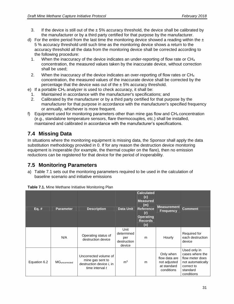
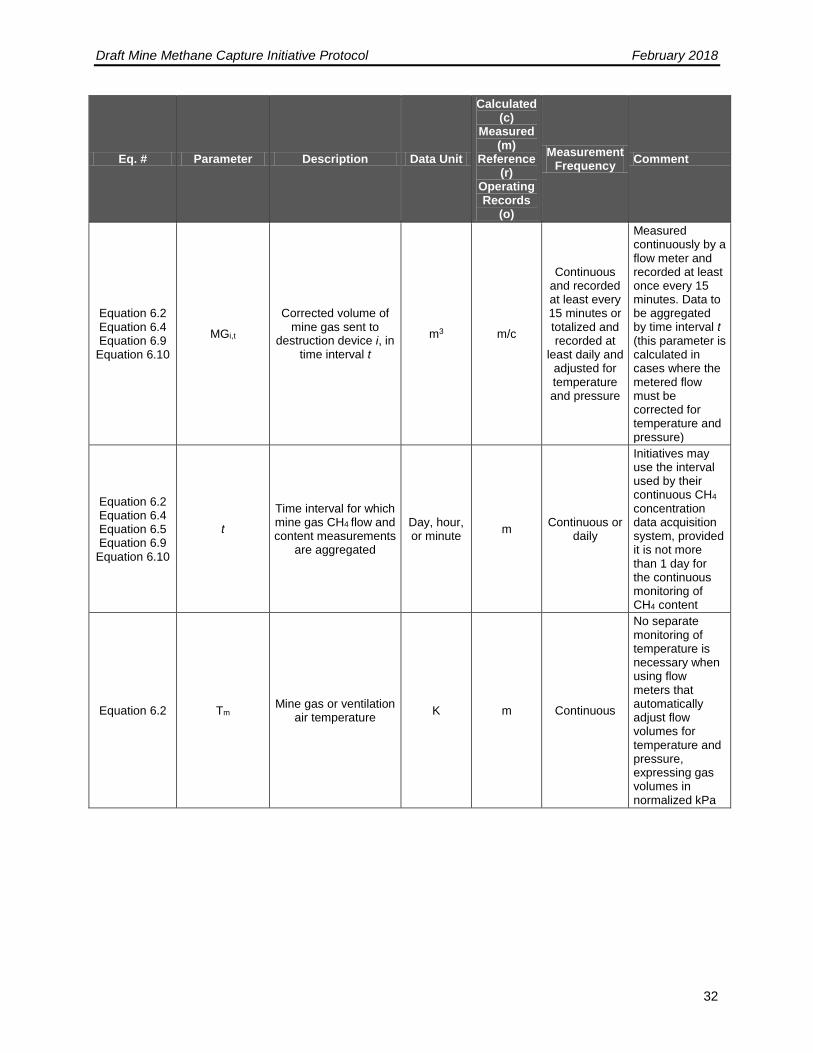
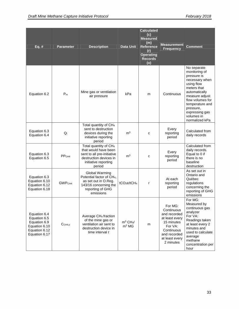
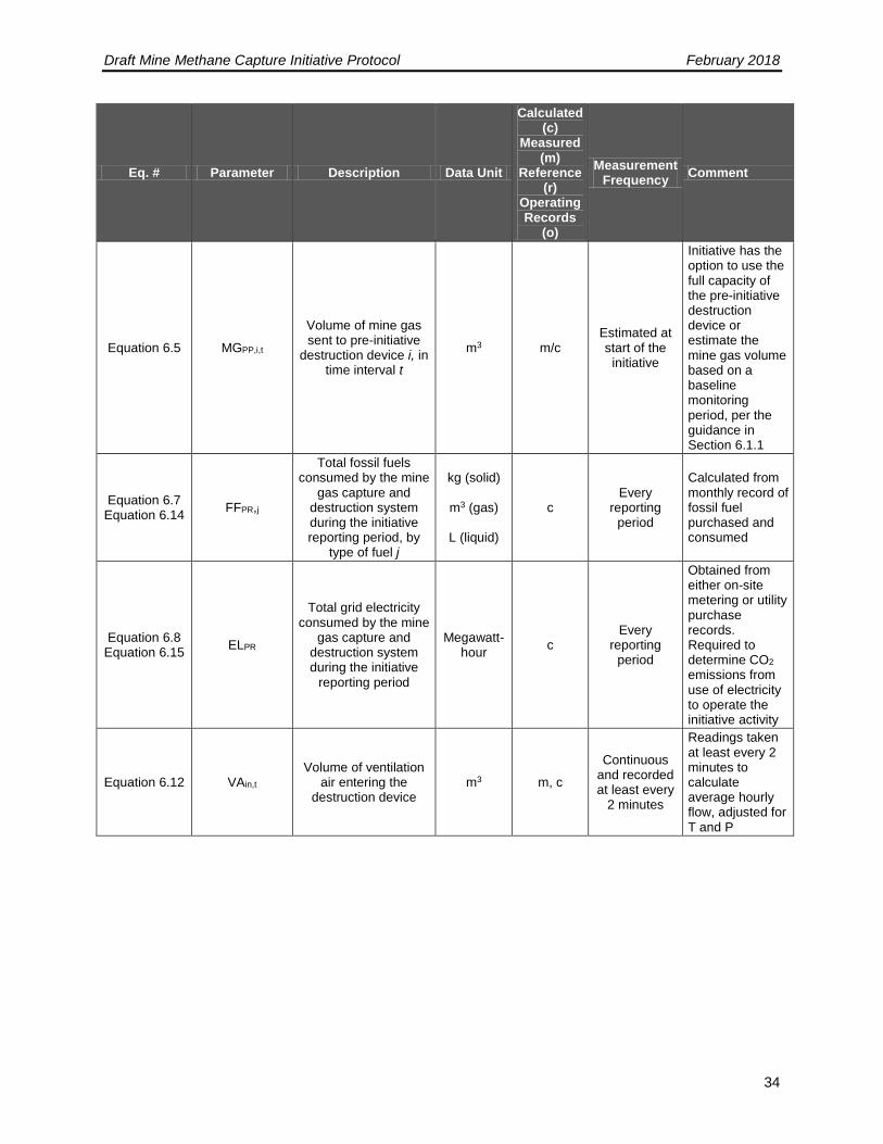
7.5 Monitoring Parameters a) Table 7.1 sets out the monitoring parameters required to be used in the calculation of
baseline scenario and initiative emissions
Table 7.1. Mine Methane Initiative Monitoring Plan
Eq. # Parameter Description Data Unit
Calculated (c)
Measured (m)
Reference (r)
Operating Records
(o)
Measurement Frequency
Comment
N/A Operating status of destruction device
Unit determined
per destruction
device
m Hourly Required for each destruction device
Equation 6.2 MGuncorrected
Uncorrected volume of mine gas sent to
destruction device i, in time interval t
m3 m
Only when flow data are not adjusted at standard conditions
Used only in cases where the flow meter does not automatically correct to standard conditions
Draft Mine Methane Capture Initiative Protocol February 2018
32
Eq. # Parameter Description Data Unit
Calculated (c)
Measured (m)
Reference (r)
Operating Records
(o)
Measurement Frequency
Comment
Equation 6.2 Equation 6.4 Equation 6.9
Equation 6.10
MGi,t
Corrected volume of mine gas sent to
destruction device i, in time interval t
m3 m/c
Continuous and recorded at least every 15 minutes or totalized and recorded at
least daily and adjusted for temperature and pressure
Measured continuously by a flow meter and recorded at least once every 15 minutes. Data to be aggregated by time interval t (this parameter is calculated in cases where the metered flow must be corrected for temperature and pressure)
Equation 6.2 Equation 6.4 Equation 6.5 Equation 6.9
Equation 6.10
t
Time interval for which mine gas CH4 flow and content measurements
are aggregated
Day, hour, or minute
m Continuous or
daily
Initiatives may use the interval used by their continuous CH4 concentration data acquisition system, provided it is not more than 1 day for the continuous monitoring of CH4 content
Equation 6.2 Tm Mine gas or ventilation
air temperature K m Continuous
No separate monitoring of temperature is necessary when using flow meters that automatically adjust flow volumes for temperature and pressure, expressing gas volumes in normalized kPa
Draft Mine Methane Capture Initiative Protocol February 2018
33
Eq. # Parameter Description Data Unit
Calculated (c)
Measured (m)
Reference (r)
Operating Records
(o)
Measurement Frequency
Comment
Equation 6.2 Pm Mine gas or ventilation
air pressure kPa m Continuous
No separate monitoring of pressure is necessary when using flow meters that automatically measure adjust flow volumes for temperature and pressure, expressing gas volumes in normalized kPa
Equation 6.3 Equation 6.4
Qi
Total quantity of CH4 sent to destruction devices during the initiative reporting
period
m3 c Every
reporting period
Calculated from daily records
Equation 6.3 Equation 6.5
PPCH4
Total quantity of CH4 that would have been sent to all pre-initiative destruction devices in
initiative reporting period
m3 c Every
reporting period
Calculated from daily records. Equal to 0 if there is no baseline destruction
Equation 6.3 Equation 6.10 Equation 6.12 Equation 6.18
GWPCH4
Global Warming Potential factor of CH4,
as set out in O.Reg. 143/16 concerning the
reporting of GHG emissions
tCO2e/tCH4 r At each
reporting period
As set out in Ontario and Québec regulations concerning the reporting of GHG emissions
Equation 6.4 Equation 6.5 Equation 6.9
Equation 6.10 Equation 6.12 Equation 6.17
CCH4,t
Average CH4 fraction of the mine gas or
ventilation air sent to destruction device in
time interval t
m3 CH4/ m3 MG
m
For MG: Continuous
and recorded at least every 15 minutes
For VA: Continuous
and recorded at least every
2 minutes
For MG: Measured by continuous gas analyzer For VA: Readings taken at least every 2 minutes and used to calculate average methane concentration per hour
Draft Mine Methane Capture Initiative Protocol February 2018
34
Eq. # Parameter Description Data Unit
Calculated (c)
Measured (m)
Reference (r)
Operating Records
(o)
Measurement Frequency
Comment
Equation 6.5 MGPP,i,t
Volume of mine gas sent to pre-initiative
destruction device i, in time interval t
m3 m/c Estimated at start of the
initiative
Initiative has the option to use the full capacity of the pre-initiative destruction device or estimate the mine gas volume based on a baseline monitoring period, per the guidance in Section 6.1.1
Equation 6.7 Equation 6.14
FFPR,j
Total fossil fuels consumed by the mine
gas capture and destruction system during the initiative reporting period, by
type of fuel j
kg (solid)
m3 (gas)
L (liquid)
c Every
reporting period
Calculated from monthly record of fossil fuel purchased and consumed
Equation 6.8 Equation 6.15
ELPR
Total grid electricity consumed by the mine
gas capture and destruction system during the initiative
reporting period
Megawatt-hour
c Every
reporting period
Obtained from either on-site metering or utility purchase records. Required to determine CO2
emissions from use of electricity to operate the initiative activity
Equation 6.12 VAin,t Volume of ventilation
air entering the destruction device
m3 m, c
Continuous and recorded at least every
2 minutes
Readings taken at least every 2 minutes to calculate average hourly flow, adjusted for T and P
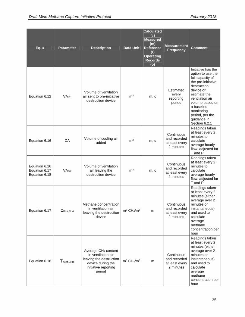
Draft Mine Methane Capture Initiative Protocol February 2018
35
Eq. # Parameter Description Data Unit
Calculated (c)
Measured (m)
Reference (r)
Operating Records
(o)
Measurement Frequency
Comment
Equation 6.12 VAPP Volume of ventilation
air sent to pre-initiative destruction device
m3 m, c
Estimated every
reporting period
Initiative has the option to use the full capacity of the pre-initiative destruction device or estimate the ventilation air volume based on a baseline monitoring period, per the guidance in Section 6.2.1
Equation 6.16 CA Volume of cooling air
added m3 m, c
Continuous and recorded at least every
2 minutes
Readings taken at least every 2 minutes to calculate average hourly flow, adjusted for T and P
Equation 6.16 Equation 6.17 Equation 6.18
VAout Volume of ventilation
air leaving the destruction device
m3 m, c
Continuous and recorded at least every
2 minutes
Readings taken at least every 2 minutes to calculate average hourly flow, adjusted for T and P
Equation 6.17 CDest,CH4
Methane concentration in ventilation air
leaving the destruction device
m3 CH4/m3 m
Continuous and recorded at least every
2 minutes
Readings taken at least every 2 minutes (either average over 2 minutes or instantaneous) and used to calculate average methane concentration per hour
Equation 6.18 Tdest,CH4
Average CH4 content in ventilation air
leaving the destruction device during the initiative reporting
period
m3 CH4/m3 m
Continuous and recorded at least every
2 minutes
Readings taken at least every 2 minutes (either average over 2 minutes or instantaneous) and used to calculate average methane concentration per hour
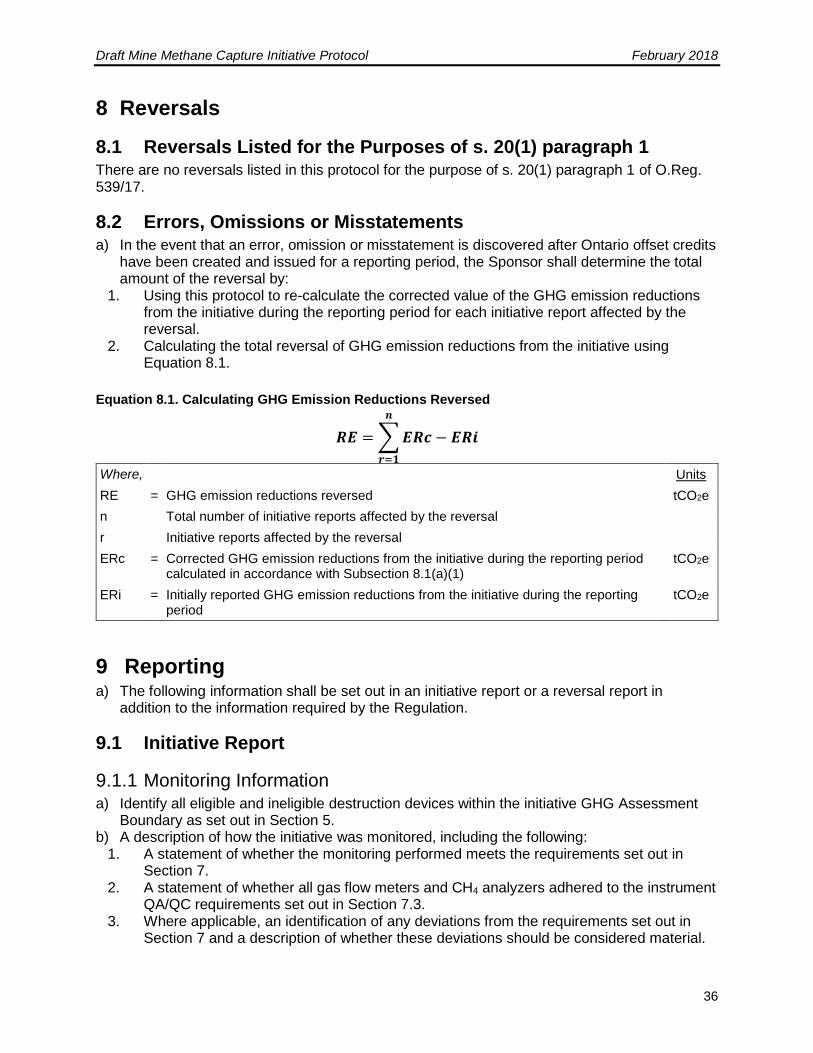
Draft Mine Methane Capture Initiative Protocol February 2018
36
8 Reversals
8.1 Reversals Listed for the Purposes of s. 20(1) paragraph 1 There are no reversals listed in this protocol for the purpose of s. 20(1) paragraph 1 of O.Reg. 539/17.
8.2 Errors, Omissions or Misstatements a) In the event that an error, omission or misstatement is discovered after Ontario offset credits
have been created and issued for a reporting period, the Sponsor shall determine the total amount of the reversal by:
1. Using this protocol to re-calculate the corrected value of the GHG emission reductions from the initiative during the reporting period for each initiative report affected by the reversal.
2. Calculating the total reversal of GHG emission reductions from the initiative using Equation 8.1.
Equation 8.1. Calculating GHG Emission Reductions Reversed
𝑹𝑬 = ∑ 𝑬𝑹𝒄 − 𝑬𝑹𝒊
𝒏
𝒓=𝟏
Where, Units
RE = GHG emission reductions reversed tCO2e
n Total number of initiative reports affected by the reversal
r Initiative reports affected by the reversal
ERc = Corrected GHG emission reductions from the initiative during the reporting period calculated in accordance with Subsection 8.1(a)(1)
tCO2e
ERi = Initially reported GHG emission reductions from the initiative during the reporting period
tCO2e
9 Reporting a) The following information shall be set out in an initiative report or a reversal report in
addition to the information required by the Regulation.
9.1 Initiative Report
9.1.1 Monitoring Information a) Identify all eligible and ineligible destruction devices within the initiative GHG Assessment
Boundary as set out in Section 5. b) A description of how the initiative was monitored, including the following:
1. A statement of whether the monitoring performed meets the requirements set out in Section 7.
2. A statement of whether all gas flow meters and CH4 analyzers adhered to the instrument QA/QC requirements set out in Section 7.3.
3. Where applicable, an identification of any deviations from the requirements set out in Section 7 and a description of whether these deviations should be considered material.
Draft Mine Methane Capture Initiative Protocol February 2018
37
c) Calibration certificates or verification reports on the calibration accuracy, from either the manufacturer or a qualified third-party certified by the manufacturer for each piece of monitoring equipment.
d) Where applicable, identification of instances where any piece of equipment failed a calibration and a description of how the data from that equipment was corrected in accordance with Section 7.3, including any calculations used.
e) Where applicable, identification of instances where the data substitution methodology set out in Section 7.4 was applied, and a description as to how the data was substituted including any calculations used.
f) Identification of the measurement frequency used for each monitoring parameter, where multiple frequencies may be used in accordance with Section 7.5Error! Reference source not found..
9.1.2 Quantification Information a) All calculations set out in Section 6, including any supporting calculations set out in Section
7, that were used. b) The reference temperature and density used. c) Identification of any source test data, if used in place of the default destruction efficiencies,
as set out in Appendix A.
9.2 Reversal Report
9.2.1 General a) Information about the circumstances and causes of the reversal including the number of
reporting periods affected. b) For each initiative report that was affected by the reversal, all information that has changed
as a result of the reversal and a description of those changes. c) In the case of an error, omission or misstatement reversal, a description of the corrective
actions taken to address the circumstances and causes of the reversal. d) Supporting documentation for each of the items in paragraphs (a) through (c) above.
9.2.2 Quantification Information a) All calculations set out in Section 8, including supporting calculations set out in Section 6
and Section 7, that were used to determine the amount of the reversal. b) Supporting documentation related to the calculations.
10 Record Keeping a) The following records and documents shall be kept in addition to the records that are
required to be kept under the Regulation: 1. The information and data required under the monitoring requirements in Section 7,
including all GHG calculations and related data inputs. 2. Information on each eligible and if applicable ineligible flow meter, CH4 analyzer and
destruction device used, including type, model number, serial number and manufacturer's maintenance and calibration procedures.
3. Maintenance documents and records relating to collection, destruction and monitoring systems including:
Draft Mine Methane Capture Initiative Protocol February 2018
38
i. For each mine gas flow meter and CH4 analyzers, records and documents relating to all instrument QA/QC activities.
ii. For a portable analyzer, time and place where measurements are taken and, for each measurement, the CH4 concentration in the mine gas.
iii. The calibration date, time and results for CH4 analyzers and flow meters, and the corrective measures applied if a piece of equipment failed to meet the requirements of this protocol: (A) Flow meter calibrations shall be documented to show that the meter was
calibrated to a range of flow rates corresponding to the flow rates expected at the mine site.
(B) CH4 analyzer calibrations shall be documented to show that the calibration was carried out to a range of temperature and pressure conditions corresponding to the range of conditions measured at the mine site.
4. Operating records showing: a. annual coal production; b. the mining method employed (required for underground mines only), e.g., room
and pillar, longwall; c. the year of initial mine operation; d. the scheduled year of mine closure, if known; and
5. All documentation related to permits related to the coal mine (e.g., mining permits, air quality, water quality, land use, system construction, etc.), as well as documentation related to any regulatory compliance inquiries, warnings, or violations.
6. All documentation related to any violations of legal requirements that apply to the initiative or that may have an impact on the amount of GHG reductions, avoidances or removals.
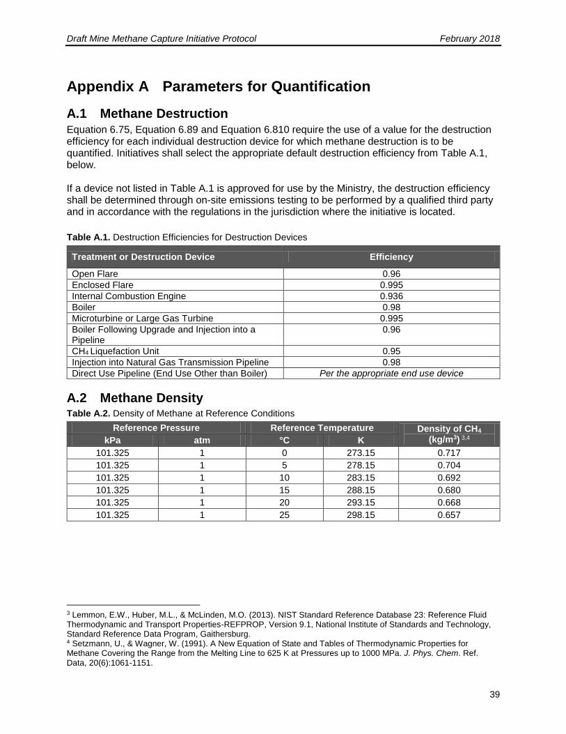
Draft Mine Methane Capture Initiative Protocol February 2018
39
Appendix A Parameters for Quantification
A.1 Methane Destruction Equation 6.75, Equation 6.89 and Equation 6.810 require the use of a value for the destruction efficiency for each individual destruction device for which methane destruction is to be quantified. Initiatives shall select the appropriate default destruction efficiency from Table A.1, below. If a device not listed in Table A.1 is approved for use by the Ministry, the destruction efficiency shall be determined through on-site emissions testing to be performed by a qualified third party and in accordance with the regulations in the jurisdiction where the initiative is located.
Table A.1. Destruction Efficiencies for Destruction Devices
Treatment or Destruction Device Efficiency
Open Flare 0.96
Enclosed Flare 0.995
Internal Combustion Engine 0.936
Boiler 0.98
Microturbine or Large Gas Turbine 0.995
Boiler Following Upgrade and Injection into a Pipeline
0.96
CH4 Liquefaction Unit 0.95
Injection into Natural Gas Transmission Pipeline 0.98
Direct Use Pipeline (End Use Other than Boiler) Per the appropriate end use device
A.2 Methane Density Table A.2. Density of Methane at Reference Conditions
Reference Pressure Reference Temperature Density of CH4
(kg/m3) 3,4 kPa atm °C K
101.325 1 0 273.15 0.717
101.325 1 5 278.15 0.704
101.325 1 10 283.15 0.692
101.325 1 15 288.15 0.680
101.325 1 20 293.15 0.668
101.325 1 25 298.15 0.657
3 Lemmon, E.W., Huber, M.L., & McLinden, M.O. (2013). NIST Standard Reference Database 23: Reference Fluid Thermodynamic and Transport Properties-REFPROP, Version 9.1, National Institute of Standards and Technology, Standard Reference Data Program, Gaithersburg. 4 Setzmann, U., & Wagner, W. (1991). A New Equation of State and Tables of Thermodynamic Properties for Methane Covering the Range from the Melting Line to 625 K at Pressures up to 1000 MPa. J. Phys. Chem. Ref. Data, 20(6):1061-1151.
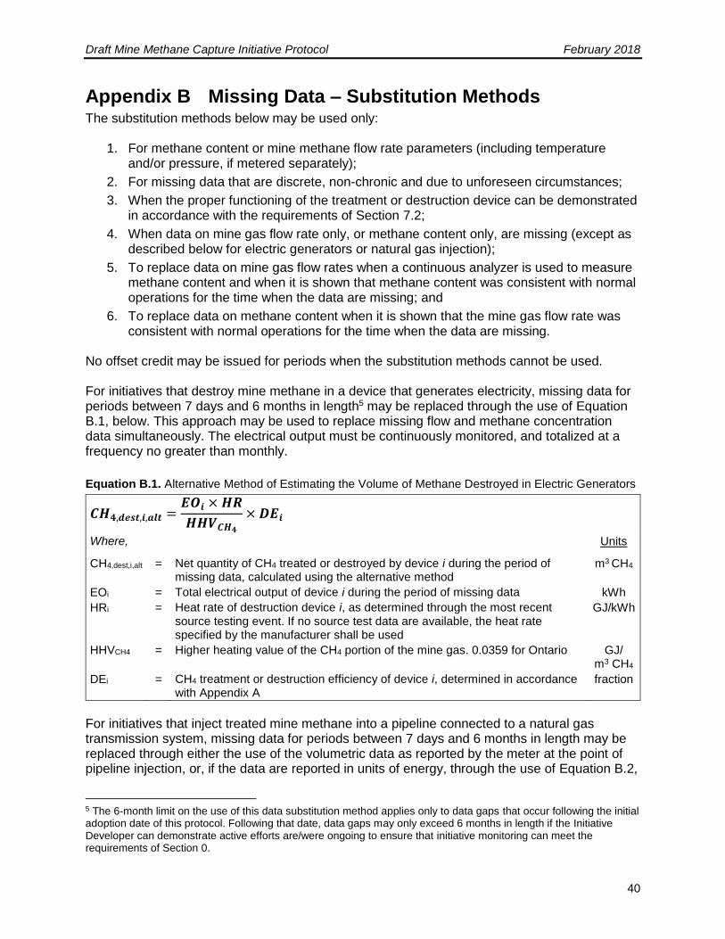
Draft Mine Methane Capture Initiative Protocol February 2018
40
Appendix B Missing Data – Substitution Methods The substitution methods below may be used only:
1. For methane content or mine methane flow rate parameters (including temperature and/or pressure, if metered separately);
2. For missing data that are discrete, non-chronic and due to unforeseen circumstances;
3. When the proper functioning of the treatment or destruction device can be demonstrated in accordance with the requirements of Section 7.2;
4. When data on mine gas flow rate only, or methane content only, are missing (except as described below for electric generators or natural gas injection);
5. To replace data on mine gas flow rates when a continuous analyzer is used to measure methane content and when it is shown that methane content was consistent with normal operations for the time when the data are missing; and
6. To replace data on methane content when it is shown that the mine gas flow rate was consistent with normal operations for the time when the data are missing.
No offset credit may be issued for periods when the substitution methods cannot be used. For initiatives that destroy mine methane in a device that generates electricity, missing data for periods between 7 days and 6 months in length5 may be replaced through the use of Equation B.1, below. This approach may be used to replace missing flow and methane concentration data simultaneously. The electrical output must be continuously monitored, and totalized at a frequency no greater than monthly.
Equation B.1. Alternative Method of Estimating the Volume of Methane Destroyed in Electric Generators
𝑪𝑯𝟒,𝒅𝒆𝒔𝒕,𝒊,𝒂𝒍𝒕 =𝑬𝑶𝒊 × 𝑯𝑹
𝑯𝑯𝑽𝑪𝑯𝟒
× 𝑫𝑬𝒊
Where, Units
CH4,dest,i,alt = Net quantity of CH4 treated or destroyed by device i during the period of missing data, calculated using the alternative method
m3 CH4
EOi = Total electrical output of device i during the period of missing data kWh
HRi = Heat rate of destruction device i, as determined through the most recent source testing event. If no source test data are available, the heat rate specified by the manufacturer shall be used
GJ/kWh
HHVCH4 = Higher heating value of the CH4 portion of the mine gas. 0.0359 for Ontario GJ/ m3 CH4
DEi = CH4 treatment or destruction efficiency of device i, determined in accordance with Appendix A
fraction
For initiatives that inject treated mine methane into a pipeline connected to a natural gas transmission system, missing data for periods between 7 days and 6 months in length may be replaced through either the use of the volumetric data as reported by the meter at the point of pipeline injection, or, if the data are reported in units of energy, through the use of Equation B.2,
5 The 6-month limit on the use of this data substitution method applies only to data gaps that occur following the initial adoption date of this protocol. Following that date, data gaps may only exceed 6 months in length if the Initiative Developer can demonstrate active efforts are/were ongoing to ensure that initiative monitoring can meet the requirements of Section 0.
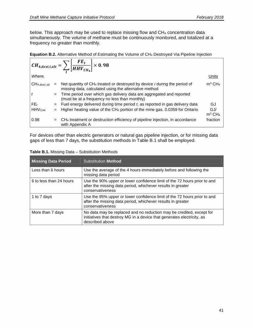
Draft Mine Methane Capture Initiative Protocol February 2018
41
below. This approach may be used to replace missing flow and CH4 concentration data simultaneously. The volume of methane must be continuously monitored, and totalized at a frequency no greater than monthly.
Equation B.2. Alternative Method of Estimating the Volume of CH4 Destroyed Via Pipeline Injection
𝑪𝑯𝟒,𝒅𝒆𝒔𝒕,𝒊,𝒂𝒍𝒕 = ∑ [𝑭𝑬𝒕
𝑯𝑯𝑽𝑪𝑯𝟒
]
𝒕
× 𝟎. 𝟗𝟖
Where, Units
CH4,dest,i,alt = Net quantity of CH4 treated or destroyed by device i during the period of missing data, calculated using the alternative method
m3 CH4
t = Time period over which gas delivery data are aggregated and reported (must be at a frequency no less than monthly)
FEt = Fuel energy delivered during time period t, as reported in gas delivery data GJ
HHVCH4 = Higher heating value of the CH4 portion of the mine gas. 0.0359 for Ontario GJ/ m3 CH4
0.98 = CH4 treatment or destruction efficiency of pipeline injection, in accordance with Appendix A
fraction
For devices other than electric generators or natural gas pipeline injection, or for missing data gaps of less than 7 days, the substitution methods in Table B.1 shall be employed.
Table B.1. Missing Data – Substitution Methods
Missing Data Period Substitution Method
Less than 6 hours Use the average of the 4 hours immediately before and following the missing data period
6 to less than 24 hours Use the 90% upper or lower confidence limit of the 72 hours prior to and after the missing data period, whichever results in greater conservativeness
1 to 7 days Use the 95% upper or lower confidence limit of the 72 hours prior to and after the missing data period, whichever results in greater conservativeness
More than 7 days No data may be replaced and no reduction may be credited, except for initiatives that destroy MG in a device that generates electricity, as described above