Embed Size (px)
Citation preview
DRAFT No.
21296
BALLASTS FOR TUBULAR FLUORESCENT LAMPS – PERFORMANCE REQUIREMENTS
SAUDI ARABIAN STANDARDS ORGANIZATION THIS DOCUMENT IS A DRAFT SAUDI STANDARD CIRCULATED FOR COMMENT. IT IS, THEREFORE SUBJECT TO CHANGE AND MAY NOT BE REFERRED TO AS A SAUDI STANDARD UNTIL APPROVED BY THE BOARD OF DIRECTORS.
SAUDI STANDARD SASO IEC 90921/2010
Foreword
The Saudi Arabian Standards Organization (SASO) has adopted the International standard No. IEC 60921:2004+Amend. 1 : 2006 “BALLASTS FOR TUBULAR FLUORESCENT LAMPS – PERFORMANCE REQUIREMENTS ”. The text of this international standard has been translated into Arabic so as to be approved as a Saudi standard without introducing any technical modification.
SAUDI STANDARD SASO IEC 90921/2010
CONTENTS
FOREWORD .............................................................. Error! Bookmark not defined. INTRODUCTION ...................................................................................................... 6 1 Scope ................................................................................................................... 7 2 Normative References .......................................................................................... 7 3 Terms and definitions........................................................................................... 7 4 General notes on tests........................................................................................... 7 5 Marking ............................................................................................................... 8 6 Voltage at terminations of lamp or starter (if any)................................................. 8
6.1 For lamps operated with a starter.................................................................. 8 6.2 For lamps operated without a starter............................................................. 9 6.3 For lamps operated without a starter (North American practice).................... 9 6.4 Maximum (r.m.s.) voltage across starter terminals with lamp operating ...... 10 6.5 For lamps with integral means of starting ................................................... 10
7 Pre-heating conditions........................................................................................ 10 7.1 For lamps operated with (integral) starter ................................................... 10 7.2 For lamps operated without starter ............................................................. 10 7.3 For lamps operated without starter (North American practice) .................... 11
8 Lamp power and current ..................................................................................... 11 8.1 For lamps operated with (integral) starter ................................................... 11 8.2 For lamps operated without starter ............................................................. 12
9 Circuit power-factor ........................................................................................... 12 10 Supply current.................................................................................................... 12 11 Maximum current in any lead to a cathode .......................................................... 12 12 Current waveform .............................................................................................. 12 13 Magnetic screening ............................................................................................ 13 14 Impedance at audio-frequencies.......................................................................... 13 Annex A (normative) Tests ..................................................................................... 14 A.1 General conditions for tests.............................................................................. 14 A.2 Additional requirements for testing reference ballasts ...................................... 14 A.3 Selection of reference lamps ............................................................................ 15 A.4 Measurement of open-circuit voltage ............................................................... 20 A.5 Measurements of pre-heating conditions .......................................................... 20 A.6 Measurement of lamp power and current .......................................................... 20 A.7 Measurement of maximum current in any lead to a cathode .............................. 23

SAUDI STANDARD SASO IEC 90921/2010 A.8 Measurement of current waveform (Figure 9) ................................................... 24 A.9 Measurement of impedance at audio-frequencies .............................................. 25 Annex B (informative) Series operation of two fluorescent lamps ............................ 28 Annex C (normative) Reference ballasts .................................................................. 29 C.1 Marking........................................................................................................... 29 C.2 Design characteristics ...................................................................................... 29 C.3 Operating characteristics.................................................................................. 29 Annex D (normative) Reference lamps ..................................................................... 31 Bibliography ............................................................................................................ 32 Figure A.1 – Circuit for measurement of voltage/current ratio .................................. 15 Figure A.2 – Circuit for measurement of power factor .............................................. 15 Figure A.3 – Circuit for selection of reference lamps (without separate cathode heating) ........................................................................... 16 Figure A.4 – Circuit for selection of reference lamps (with separate cathode heating) ................................................................................................................... 18 Figure A.5 – Circuit for calibration of cathode transformers ..................................... 19 Figure A.6 – Measurement of power and current output (lamps with starter) ............. 21 Figure A.7 – Measurement of power and current output (lamps without starter) ........ 23 Figure A.8 – Measurement of maximum current in any lead to a cathode .................. 24 Figure A.9 – Measurement of current waveform ....................................................... 25 Figure A.10 – Measurement of impedance at audio-frequencies – Method A ............. 26 Figure A.11 – Measurement of impedance at audio frequencies – Method B ............. 27
SAUDI STANDARD SASO IEC 90921/2010
INTRODUCTION
This standard covers performance requirements for ballasts for tubular fluorescent lamps. It should be read in conjunction with IEC 61347-2-8, with which all ballasts covered by the present standard should comply.
Unless otherwise stated on the lamp data sheet mentioned in IEC 60081 and IEC 60901, it may be expected that ballasts which comply with this standard, when associated with lamps complying with IEC 60081 or IEC 60901, and, where appropriate, operated with a starter complying with IEC 60155 or starting devices complying with IEC 60927, will ensure satisfactory starting of the lamps at an air temperature immediately around the lamps between 10 °C and 35 °C and for voltages between 92 % and 106 % of rated supply voltage, and also proper operation between 10 °C and 50 °C at rated supply voltage.
The compatibility of lamps and ballasts is evaluated with the use of special inductive ballasts called “reference ballasts” having particular characteristics which are stable and reproducible. These ballasts are used when testing commercial ballasts and when selecting reference lamps. Moreover, the testing of ballasts presents particular difficulties, which require a proper definition of testing methods. Such tests will generally be made with reference lamps and, in particular, by comparing the results obtained when such lamps are operated on a reference ballast with the results obtained when the same lamps are operated on the ballast being tested.
NOTE Requirements are also included for all those features of reference ballast construction and performance which are considered necessary to ensure accurate and reproducible results when testing ballasts, particularly with regard to the selection of reference lamps.
For checking the lamp power and current of lamps operated without a starter, this standard specifies a measurement in a reference ballast circuit that makes no provision for separate power sources to heat the cathodes during lamp operation. Although the influence on the ballast specification is small, it has nevertheless been deemed useful for some pre-heated low-voltage cathode lamps, operated without a starter, to include provision for two alternative methods of measurement of lamp power and current:
a) measurement of lamp power and current without additional cathode heating; b) measurement of lamp power and current with additional cathode heating.
The test method to be adopted for appraisal should be stated by the manufacturer.
Two alternative circuits are specified for the measurement of impedance at audio frequencies. The less complex circuit could be used when there is no doubt about the inductive character of the impedance. If there is any doubt, the other circuit should be be used.

SAUDI STANDARD SASO IEC 90921/2010
BALLASTS FOR TUBULAR FLUORESCENT LAMPS – PERFORMANCE REQUIREMENTS
1 Scope This standard specifies performance requirements for ballasts, excluding resistance types, for use on a.c. supplies up to 1 000 V at 50 Hz or 60 Hz, associated with tubular fluorescent lamps with pre-heated cathodes operated with or without a starter or starting device and having rated wattages, dimensions and characteristics as specified in IEC 60081 and 60901. It applies to complete ballasts and their component parts such as resistors, transformers and capacitors.
A.C. supplied electronic ballasts for tubular fluorescent lamps for high frequency operation specified in IEC 61347-2-3 are excluded from the scope of this standard. NOTE In some regions there are laws on EMC for luminaires. The controlgear also contributes to this EMC behaviour. See Bibliography for further references.
2 Normative References The following referenced documents are indispensable for the application of this document. For dated references, only the edition cited applies. For undated references, the latest edition of the referenced document (including any amendments) applies.
IEC 60081, Double-capped fluorescent lamps – Performance specifications
IEC 60901, Single-capped fluorescent lamps – Performance specifications
IEC 61347-1, Lamp controlgear – General and safety requirements
IEC 61347-2-8, Lamp controlgear – Particular requirements for ballasts for fluorescent lamps
3 Terms and definitions For the purposes of the present document, the definitions of IEC 61347-2-8 together with the following apply.
3.1 (peak) lead circuit ballast ballast having a leading lamp current with respect to the line voltage as a result of a capacitor which is connected in series with the lamp
4 General notes on tests 4.1 Tests according to this specification are type tests.
NOTE The requirements and tolerances permitted by this standard are based on testing of a type test sample submitted by the manufacturer for that purpose. In principle this type test sample should consist of units having characteristics typical of the manufacturer’s production and be as close to the production centre point values as possible.
It may be expected with the tolerances given in the standard that products manufactured in accordance with the type test sample will comply with the standard for the majority of the production.

SAUDI STANDARD SASO IEC 90921/2010
Due to the production spread, it is inevitable, however, that there may sometimes be ballasts outside the specified tolerances.
For guidance of sampling plans and procedures for inspection by attributes, see IEC 60410.
4.2 The tests shall be carried out in the order of the clauses, unless otherwise specified.
4.3 One specimen shall be submitted to all tests.
4.4 In general all tests are made on each type of ballast or, where a range of similar ballasts is involved, for each rated wattage in the range or on a representative selection from the range as agreed with the manufacturer.
4.5 The tests shall be made under the conditions specified in Annex A.
4.6 All ballasts specified in this standard shall comply with the requirements of IEC 61347-2-8.
4.7 Attention is drawn to lamp performance standards which contain “information for ballast design”; this should be followed for proper lamp operation; however, this standard does not require the testing of lamp performance as part of the type test approval for ballasts.
5 Marking The following information shall be included either on the ballast or be made available in the manufacturer’s catalogue or the like:
5.1 Circuit power-factor, for example λ 0,85.
If the power-factor is less than 0,85 leading, it shall be followed by the letter C, for example λ 0,80 C.
For ballasts intended for the additional application of operated lamps in series, the appropriate power-factors shall be included.
The following additional marking shall be included, if appropriate:
5.2 The symbol Z which indicates that the ballast is designed to comply with the conditions for audio-frequency impedance (see Clause 14).
6 Voltage at terminations of lamp or starter (if any)
The test shall be carried out in accordance with the measuring conditions of A.4.
6.1 For lamps operated with a starter A ballast, when operated at any voltage between 92 % and 106 % of its rated voltage, shall provide the following open-circuit voltages:
a) at terminations of the starter, an r.m.s voltage of at least the value given in IEC 60081 or IEC 60901 on the relevant lamp data sheet;
b) at lamp terminations, a peak voltage (excluding the surge of the starter) not exceeding the value given in IEC 60081 or IEC 60901 on the relevant lamp data sheet.
When ballasts are designed to operate lamps in parallel circuits, the relevant requirements shall be met for each separate lamp, even in the most adverse load conditions.
SAUDI STANDARD SASO IEC 90921/2010 6.2 For lamps operated without a starter
A ballast, when operated at any voltage between 92 % and 106 % of its rated voltage, shall provide an open-circuit voltage at lamp terminations such that:
a) its r.m.s. value is at least the value given in IEC 60081 or IEC 60901 on the relevant lamp data sheet;
b) its peak value does not exceed the value given in IEC 60081 or IEC 60901 on the relevant lamp data sheet;
c) its crest factor (ratio of peak value to r.m.s. value) of open circuit voltage does not exceed the value given in IEC 60081 or IEC 60901 on the relevant lamp data sheet.
When ballasts are designed to operate lamps in parallel circuits, the relevant requirements shall be met for each separate lamp, even in the most adverse load conditions. NOTE 1 For the checking of open-circuit voltage at lamp terminations, the maximum value of the four possible measurements between lamp terminals is taken
NOTE 2 For ballasts with a step-up transformer it is likely that a capacitor is used in series to form lead circuit or peak lead circuit ballasts. A lead circuit ballast typically has an open circuit voltage crest factor of 1,55 to 2,0 and in a peak lead ballast it is 2,0 to 2,3.
6.3 For lamps operated without a starter (North American practice) A ballast, when operated at any voltage between 90 % and 110 % of its rated voltage, shall provide an open-circuit voltage at lamp terminations such that:
a) its r.m.s. value is not less than the minimum and not greater than the maximum values given in IEC 60081 or IEC 60901 on the relevant lamp data sheet;
b) its peak value to starting aid is at least the value given in IEC 60081 or IEC 60901 on the relevant lamp data sheet;
c) its crest factor (ratio of peak value to r.m.s. value) of open circuit voltage across lamp and to starting aid does not exceed the value given in IEC 60081 or IEC 60901 on the relevant lamp data sheet.
When ballasts are designed to operate lamps in parallel circuits, the relevant requirements shall be met for each separate lamp, even in the most adverse load conditions. NOTE 1 For the checking of open-circuit voltage at lamp terminations, the maximum value of the four possible measurements between lamp terminals is taken.
NOTE 2 For ballasts with a step-up transformer it is likely that a capacitor is used in series to form lead circuit or peak lead circuit ballasts. A lead circuit ballast typically has an open circuit voltage crest factor of 1,55 to 2,0 and in a peak lead circuit ballast it is 2,0 to 2,3.
Starting aid capacitor sizes are specified not less than the minimum and not greater than the maximum on the relevant lamp data sheet. In two-lamp series ballasts, the capacitor shall shunt the lamp furthest from ground potential. For three-lamp series ballasts, a capacitor shall shunt the two lamps furthest from ground potential. A second capacitor of the same size shall shunt the lamp furthest from ground. If the peak voltage to ground

SAUDI STANDARD SASO IEC 90921/2010
exceeds the minimum by 30 % the second capacitor may shunt either of the two shunted lamps.
6.4 Maximum (r.m.s.) voltage across starter terminals with lamp operating When a ballast is operating with a reference lamp and is connected to any voltage between 92 % and 106 % of the rated supply voltage at rated frequency, the voltage across the starter terminations shall not exceed the maximum value given in IEC 60081 on the relevant lamp data sheet.
These limits apply both when the lamp is first ignited and after it has warmed up.
When the ballasts are designed to operate lamps in parallel circuits, the relevant requirements shall be met for each separate lamp, under the most adverse load conditions.
6.5 For lamps with integral means of starting A ballast, when operated at any voltage between 92 % and 106 % of its rated voltage, shall provide an open-circuit voltage at lamp terminations such that:
a) its r.m.s value is at least the value given in IEC 60901 on the relevant lamp data sheet.
b) its peak value does not exceed that value given in IEC 60901 on the relevant lamp data sheet.
7 Pre-heating conditions The test shall be carried out in accordance with the measuring conditions of A.5. NOTE A marked capacitor tolerance of 10 %, which is typical for shunt connected capacitors, is unsuitable for series capacitors due to the summation of capacitor and ballast tolerances which, when unfavourable tolerances coincide, may lead to poor lamp performance.
Consequently, and in order to satisfy the requirements specified on the relevant lamp data sheets in IEC 60081 or IEC 60901, depending on the tolerances of the series choke component of the ballast either the capacitor tolerances should be narrow or the series connected inductive reactance and capacitor should be selected so that unfavourable tolerances do not coincide.
7.1 For lamps operated with (integral) starter A ballast, when operated at any voltage between 92 % and 106 % of its rated supply voltage and at rated frequency, shall provide a pre-heating current as specified on the relevant lamp data sheet in IEC 60081 or IEC 60901.
For lamps where such data are not given in IEC 60081 or IEC 60901, the pre-heating current shall be as specified by the lamp manufacturer.
7.2 For lamps operated without starter
With an objective dummy load resistor of the value specified in the relevant lamp data sheet in IEC 60081 substituted for each lamp cathode, and with the ballast under test operated at any voltage between 92 % and 106 % of its rated voltage, the ballast shall present a voltage across each dummy load
SAUDI STANDARD SASO IEC 90921/2010
resistor not less than the minimum and not greater than the maximum specified in the relevant lamp data sheet.
For those ballasts which are intended for use with high resistance cathode lamps and which present a voltage across each dummy load resistor which exceeds the maximum specified in the relevant lamp data sheet, the following additional test procedure shall apply.
The objective dummy load resistors shall be replaced by resistors with values derived from the following equation:
Ω×
=n12
011I
R,
,
where In is the nominal running current of the lamp specified in the relevant lamp data sheet.
With the ballast under test operated at any voltage between 92 % and 106 % of its rated supply voltage the current passed by each resistor shall not exceed 2,1 times the nominal running current of the lamp.
7.3 For lamps operated without starter (North American practice) With a substitution resistor of the value specified in IEC 60081 or IEC 60901 on the relevant lamp data sheet substituted for each lamp cathode, and with the ballast under test operated at rated voltage, the ballast shall present a preheat cathode voltage across the substitution resistor not less than the minimum and not greater than the maximum specified on the relevant lamp data sheet. Where one winding operates two cathodes in parallel, the substitution value should be half the given value. In addition during operation the ballast under test operated at rated voltage, shall operate the lamp cathodes at an operating cathode voltage not less than the minimum and not greater than the maximum specified on the relevant lamp data sheet.
8 Lamp power and current The test shall be carried out in accordance with the requirements of Clause A.6.
8.1 For lamps operated with (integral) starter Unless otherwise specified on the relevant lamp data sheet, the ballast shall limit the power and current of a reference lamp to not less than 92,5 % for the power and not more than 115 % for the current of the corresponding values delivered to the same lamp when operated with a reference ballast. Both the reference ballast and the ballast under test shall have the same rated frequency and each shall be operated at its rated voltage.
For ballasts intended for the additional application of operating lamps in series, each lamp not exceeding 20 W rating, the limits at rated voltage are widened by an additional 5 %, i.e. 87,5 % for power and 120 % for current at rated voltage instead of 92,5 % and 115 % respectively. The reference ballast data used for this test shall be the sum of the individual lamp powers. NOTE A summary of ballasts suitable for series operation of two fluorescent lamps and which do not need further testing, is given in Annex B
SAUDI STANDARD SASO IEC 90921/2010 8.2 For lamps operated without starter
The ballast shall limit the arc current delivered to the reference lamp to a value not exceeding 115 % of that delivered to the same lamp when it is operated with a reference ballast.
The power supplied to the lamp shall be such that the luminous flux from a reference lamp shall be not less than 90 % of the luminous flux from the same reference lamp when operated on a reference ballast in a circuit either with or without separate cathode heating, as may be required by the measurement method being used (see Annex A).
For those lamps where both methods of measurement of electrical and luminous characteristics are specified on the relevant lamp data sheet of IEC 60081, the manufacturer shall state the method to be used.
For these tests, the reference ballast shall have the same rated frequency as the ballast under test and each of them shall be operated at its rated voltage.
9 Circuit power-factor The measured circuit power-factor shall not differ from the marked value by more than 0,05 when the ballast is operated with one or more reference lamps and the whole combination is supplied at its rated voltage and frequency. In cases where a minimum value of power-factor is required for a high power-factor ballast, it shall be 0,85 measured under the conditions stated above. For these high power-factor ballasts, the measured value shall in no case be less than 0,85. NOTE The United States of America requires a power-factor of at least 0,9 for high power-factor ballasts.
10 Supply current At rated voltage, the supply current to the ballast shall not differ by more than 10 % from the value marked on the ballast when the latter is operated with a reference lamp.
11 Maximum current in any lead to a cathode This requirement applies only to ballasts for lamps operated without starter, when tested in accordance with the requirements of Clause A.7.
In normal operation and at a supply voltage of 106 % of the rated value, the current flowing in any one of the cathode terminations shall not exceed the value given on the relevant lamp data sheet of IEC 60081 or IEC 60901.
12 Current waveform
• Lamp operating current waveform The test shall be carried out in accordance with the requirements of Clause A.8.
The ballast shall be operated at its rated voltage with a reference lamp or lamps. After lamp stabilisation, the waveform of the lamp operating current shall comply with the following conditions.
a) Successive half-cycles shall present similar forms on an oscilloscope and their peak values shall be equal to within 5 %.

SAUDI STANDARD SASO IEC 90921/2010
If measurement with the oscilloscope leaves any doubt, the requirement shall be deemed as met if any harmonic component does not exceed 2,5 % of the fundamental current.
b) The maximum ratio of peak value to r.m.s. value shall not exceed 1,7.
13 Magnetic screening The ballast shall be effectively screened against the influence of adjacent ferromagnetic materials.
Compliance is checked by the following test.
The ballast shall be operated at rated voltage with an appropriate lamp. After stabilisation, a steel plate 1mm thick and of length and breadth greater than those of the ballast under test shall be successively placed in direct contact with the bottom plate of the ballast and at a distance of 1 mm from each face of the latter.
During this operation, the lamp current shall be measured and shall not change by more than 2 % due to the presence of the steel plate.
14 Impedance at audio-frequencies Ballasts marked with the audio-frequency symbol shall be tested using one of the circuits shown in Clause A.9.
For every signal frequency between 400 Hz and 2 000 Hz, the impedance of the ballast when operated with a reference lamp supplied at its rated voltage and frequency shall be inductive in characteristic. Its impedance in ohms shall be at least equal to the resistance of the resistor, which would dissipate the same power as the lamp/ballast combination when operated at its rated voltage and frequency.
The ballast impedance is measured with a signal voltage equal to 3,5 % of the rated supply voltage of the ballast.
Between 250 Hz and 400 Hz, the impedance shall be at least equal to half the minimum value required for frequencies between 400 Hz and 2 000 Hz. NOTE 1 Radio interference suppressers consisting of capacitors of less than 0,2 µF (total value) which may be incorporated in the ballast may be disconnected for this test.
NOTE 2 In some countries, only ballasts complying with the requirements of this clause are allowed.
SAUDI STANDARD SASO IEC 90921/2010
Annex A (normative)
Tests
A.1 General conditions for tests A.1.1 The general requirements of Annex H of IEC 61347-1 apply but, for certain
tests, for example checking the requirements of Clause A.8, considerably greater purity of waveform of the supply is necessary, particularly in cases where capacitors are connected directly or indirectly in parallel with the supply. Special arrangements for correction of supply waveform may then be necessary.
A.1.2 Magnetic effects Unless otherwise specified, no magnetic object shall be allowed within 25 mm of any face of the reference ballast or the ballast under test.
A.1.3 Mounting and connections of reference lamps a) Mounting
In order to ensure that the electrical characteristics of the reference lamps are consistent, they shall be mounted as indicated on the relevant lamp data sheet. Where no mounting instructions are given on the relevant lamp data sheet, lamps shall be mounted horizontally.
It is recommended that lamps be allowed to remain permanently undisturbed in their lampholders.
b) Reference lamps operated with (integral) starter
The lamps shall be aged with one disposition of contact connections only, and shall be used in the same disposition (see A.6).
c) Reference lamps operated without starter
The above conditions shall be complied with so far as the identification of the ballast terminations corresponding to the main circuit will permit.
A.1.4 Reference lamp stability a) A lamp shall be brought to a condition of stable operation before carrying out measurements. No swirling shall be present
b) The characteristics of a lamp shall be checked immediately before and immediately after each series of tests.
A.1.5 Reference ballasts and reference lamps shall comply with Annexes C and D respectively.
A.2 Additional requirements for testing reference ballasts
A.2.1 General The measurements shall not be made on the reference ballast until steady temperature conditions are reached.
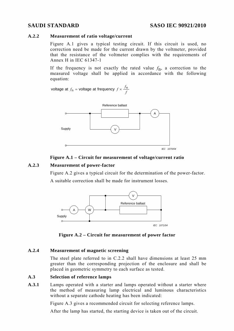
SAUDI STANDARD SASO IEC 90921/2010 A.2.2 Measurement of ratio voltage/current
Figure A.1 gives a typical testing circuit. If this circuit is used, no correction need be made for the current drawn by the voltmeter, provided that the resistance of the voltmeter complies with the requirements of Annex H in IEC 61347-1
If the frequency is not exactly the rated value fn, a correction to the measured voltage shall be applied in accordance with the following equation:
ff
ff nn frequencyatvoltageatvoltage ×=
Reference ballast
A
VSupply
IEC 1070/04 Figure A.1 – Circuit for measurement of voltage/current ratio
A.2.3 Measurement of power-factor Figure A.2 gives a typical circuit for the determination of the power-factor.
A suitable correction shall be made for instrument losses.
Reference ballast
V
W A
Supply
IEC 1071/04
Figure A.2 – Circuit for measurement of power factor
A.2.4 Measurement of magnetic screening
The steel plate referred to in C.2.2 shall have dimensions at least 25 mm greater than the corresponding projection of the enclosure and shall be placed in geometric symmetry to each surface as tested.
A.3 Selection of reference lamps A.3.1 Lamps operated with a starter and lamps operated without a starter where
the method of measuring lamp electrical and luminous characteristics without a separate cathode heating has been indicated:
Figure A.3 gives a recommended circuit for selecting reference lamps.
After the lamp has started, the starting device is taken out of the circuit.

SAUDI STANDARD SASO IEC 90921/2010
This does not apply to lamps with integral means of starting.
When stable operating conditions are reached, the current, voltage and power of the lamp are measured for compliance with Annex D.
When measuring the voltage or power of the lamp, the potential circuit of the instrument not in use is open.
When measuring the lamp wattages, no corrections shall be made for the wattmeter dissipation (the common connection being made on the lamp side of the current coil). NOTE The reference to the absence of a correction for the consumption of the voltage circuit of the wattmeter arises from the fact that, in most cases, at the same supply voltage, the said load compensates approximately for the reduction of the power consumption of the lamp caused by the parallel connection of the voltage circuit of the wattmeter.
If any doubts are felt on this point, it will always be possible to evaluate the compensation error by repeating the measurements with other values of the load in parallel with the lamp. This is done by adding resistances in parallel and reading, each time, the power measured by the wattmeter. It is then possible to extrapolate the results obtained in order to determine the true wattage in the absence of any parallel load.
Reference ballast
V
WA
V
Supply
Ref
eren
ce la
mp Starter
IEC 1072/04
Figure A.3 – Circuit for selection of reference lamps
(without separate cathode heating)
SAUDI STANDARD SASO IEC 90921/2010 A.3.2 Lamps operated without a starter where the method of measuring lamp
electrical and luminous characteristics with separate cathode heating has been indicated:
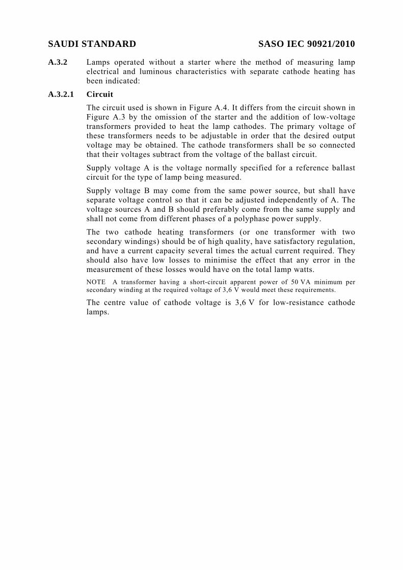
A.3.2.1 Circuit The circuit used is shown in Figure A.4. It differs from the circuit shown in Figure A.3 by the omission of the starter and the addition of low-voltage transformers provided to heat the lamp cathodes. The primary voltage of these transformers needs to be adjustable in order that the desired output voltage may be obtained. The cathode transformers shall be so connected that their voltages subtract from the voltage of the ballast circuit.
Supply voltage A is the voltage normally specified for a reference ballast circuit for the type of lamp being measured.
Supply voltage B may come from the same power source, but shall have separate voltage control so that it can be adjusted independently of A. The voltage sources A and B should preferably come from the same supply and shall not come from different phases of a polyphase power supply.
The two cathode heating transformers (or one transformer with two secondary windings) should be of high quality, have satisfactory regulation, and have a current capacity several times the actual current required. They should also have low losses to minimise the effect that any error in the measurement of these losses would have on the total lamp watts. NOTE A transformer having a short-circuit apparent power of 50 VA minimum per secondary winding at the required voltage of 3,6 V would meet these requirements.
The centre value of cathode voltage is 3,6 V for low-resistance cathode lamps.

SAUDI STANDARD SASO IEC 90921/2010
V V
V
A W
T1
T2
Reference ballast
Supply A
Supply B
WIEC 1073/04
NOTE Independent supplies are permitted to transformers T1 and T2 provided the delivered voltages have the same phase.
Figure A.4 – Circuit for selection of reference lamps (with separate cathode heating)
A.3.2.2 Calibration Each cathode transformer (or pair of transformers) shall be individually calibrated to determine the power loss that will exist during normal operation.
This power loss will vary with the current to be supplied to the particular type of cathode involved. These loss values need to be determined only once for a given transformer for each cathode type. The appropriate transformer loss can then be applied to the measurements of the various types of lamps.
It is convenient to obtain a “voltage calibration” on each transformer; this involves determining the primary voltage that should be set in order to obtain the required secondary output voltage. This calibration, although not entirely essential, makes it possible to use primary voltage settings in all routine work, thus avoiding the need for constant use of the more fragile low-range thermocouple voltmeters.
The circuit used in making the calibration is shown in Figure A.5. Each secondary winding should be connected to a substitution resistor having the electrical characteristics specified for the particular cathode type involved. The primary voltage should be adjusted so that the average of the two secondary voltages is 3,6 V and the value of the primary voltage should then be recorded. It is essential that this calibration be repeated for any other cathode types with which the transformer is to be used.
SAUDI STANDARD SASO IEC 90921/2010
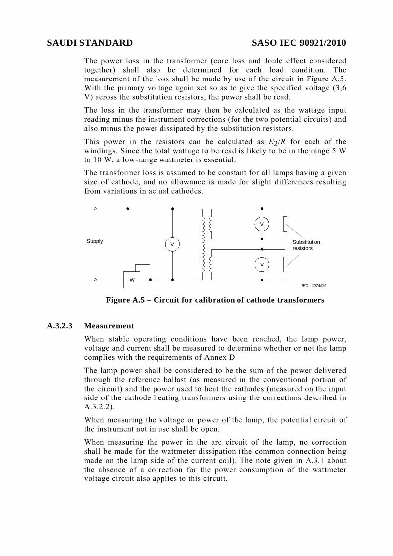
The power loss in the transformer (core loss and Joule effect considered together) shall also be determined for each load condition. The measurement of the loss shall be made by use of the circuit in Figure A.5. With the primary voltage again set so as to give the specified voltage (3,6 V) across the substitution resistors, the power shall be read.
The loss in the transformer may then be calculated as the wattage input reading minus the instrument corrections (for the two potential circuits) and also minus the power dissipated by the substitution resistors.
This power in the resistors can be calculated as E2/R for each of the windings. Since the total wattage to be read is likely to be in the range 5 W to 10 W, a low-range wattmeter is essential.
The transformer loss is assumed to be constant for all lamps having a given size of cathode, and no allowance is made for slight differences resulting from variations in actual cathodes.
V
V
V Substitution resistors
Supply
W IEC 1074/04
Figure A.5 – Circuit for calibration of cathode transformers
A.3.2.3 Measurement
When stable operating conditions have been reached, the lamp power, voltage and current shall be measured to determine whether or not the lamp complies with the requirements of Annex D.
The lamp power shall be considered to be the sum of the power delivered through the reference ballast (as measured in the conventional portion of the circuit) and the power used to heat the cathodes (measured on the input side of the cathode heating transformers using the corrections described in A.3.2.2).
When measuring the voltage or power of the lamp, the potential circuit of the instrument not in use shall be open.
When measuring the power in the arc circuit of the lamp, no correction shall be made for the wattmeter dissipation (the common connection being made on the lamp side of the current coil). The note given in A.3.1 about the absence of a correction for the power consumption of the wattmeter voltage circuit also applies to this circuit.

SAUDI STANDARD SASO IEC 90921/2010 A.4 Measurement of open-circuit voltage
A.4.1 For lamps operated with starter For the measurement of the open-circuit voltage at starter terminations, the lamp cathodes shall be replaced by a resistor having the value given in IEC 60081 or IEC 60901 on the relevant lamp data sheet.
A.4.2 For lamps operated without starter For the measurement of the open-circuit voltage at the terminals of the lamp, each cathode shall be replaced by a resistor of the objective value given in IEC 60081 or IEC 60901 on the relevant lamp data sheet.
The appropriate value of the voltage is the highest of the four possible measurements.
A.4.3 For lamps with integral means of starting For the measurement of the open-circuit voltage at the terminals of the lamp, the lamp cathodes shall be replaced by a resistor having the value given in IEC 60901 on the relevant lamp data sheet.
A.5 Measurements of pre-heating conditions
A.5.1 For lamps operated with (integral) starter For the measurement of the pre-heating current, the two lamp cathodes shall be replaced by a resistor having the value given in IEC 60081 or IEC 60901 on the relevant lamp data sheet.
A.5.2 For lamps operated without starter For the measurement of the pre-heating current, the value of the dummy resistor shall take into account the internal resistance of the voltmeters.
A.6 Measurement of lamp power and current
A.6.1 For lamps operated with (integral) starter. Figure A.6 gives an example of a suitable testing circuit.
Measurements are made with the starting device taken out of circuit.
This does not apply to lamps with integral means of starting.
In the lamp circuit, potential circuits shall not be connected across the pins or contacts used for the starter.
When measuring the voltage or power of the lamp, the potential circuit of the instrument not in use is open.
When measuring lamp wattages, no correction shall be made for the wattmeter dissipation (the common connection being made on the lamp side of the current coil).
To reduce the new stabilisation period of the lamp after transferring from one ballast circuit to another, a quick-switching technique should be adopted. During the switching, the connections of the individual pins or contacts to the same reference lamp shall not be changed. NOTE The reference to the absence of a correction for the dissipation of the voltage of the wattmeter arises from the fact that, in most cases, at the same supply voltage, the load
SAUDI STANDARD SASO IEC 90921/2010
compensates approximately for the reduction of the power dissipation of the lamp caused by the parallel connection of the voltage circuit of the wattmeter.
If any doubts are felt on this point, it will always be possible to evaluate the compensation error by repeating the measurement with other values of the load in parallel with the lamp. This is done by adding resistances in parallel and reading, each time, the power measured by the wattmeter. It is then possible to extrapolate the results obtained in order to determine the true wattage in the absence of any parallel load.
V
WA
Ref
eren
ce la
mp Starter V
V
Ballast under test
Reference ballast
Supply
Supply
IEC 1075/04
Figure A.6 – Measurement of power and current output (lamps with
starter)
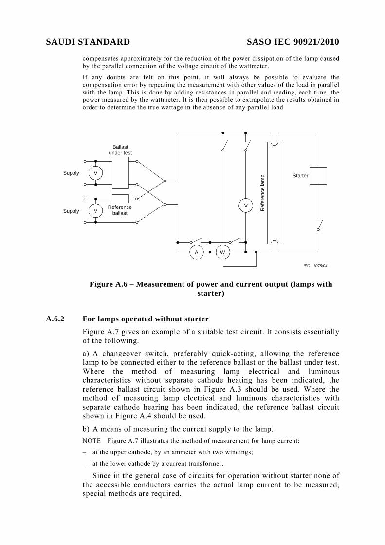
A.6.2 For lamps operated without starter Figure A.7 gives an example of a suitable test circuit. It consists essentially of the following.
a) A changeover switch, preferably quick-acting, allowing the reference lamp to be connected either to the reference ballast or the ballast under test. Where the method of measuring lamp electrical and luminous characteristics without separate cathode heating has been indicated, the reference ballast circuit shown in Figure A.3 should be used. Where the method of measuring lamp electrical and luminous characteristics with separate cathode hearing has been indicated, the reference ballast circuit shown in Figure A.4 should be used.
b) A means of measuring the current supply to the lamp. NOTE Figure A.7 illustrates the method of measurement for lamp current:
– at the upper cathode, by an ammeter with two windings;
– at the lower cathode by a current transformer.
Since in the general case of circuits for operation without starter none of the accessible conductors carries the actual lamp current to be measured, special methods are required.

SAUDI STANDARD SASO IEC 90921/2010
Two methods of measurement for this purpose are shown in Figure A.7; other methods giving the same results are acceptable.
One method of test uses an ammeter with two windings indicating the sum of the two currents in the windings. The windings are inserted in the conductors connected to the same cathode (see the top of Figure A.7).
To compensate for the disturbance caused by the insertion of the instrument in a parallel heating circuit, a second measurement is taken after inserting in each conductor an additional resistance equal to that of the corresponding circuit of the ammeter.
Let I1 and I2 be the two successive readings of the current measured, then the true value of the lamp current in normal operation is given by the following:
I = I1 + (I1 – I2)
if the conditions of Annex H of IEC 61347-1 are complied with. Another method of test using a current transformer is as follows: The combination of two conductors leading to one lamp cathode is wound with a given number of turns round the core of a suitable instrument-type current transformer.
A suitable current measuring arrangement (e.g. a thermocouple connected to a millivoltmeter) is connected to the secondary terminals of this transformer.
This combination provides a means of measuring the resulting current flowing in the two conductors. It is calibrated in advance by connecting it with a lamp in a circuit where the current flowing in the latter can be measured by ordinary procedure (for example, in the circuit of the reference ballast).
NOTE By using a current transformer, the reflected impedance in the lamp circuit of the measuring arrangement can easily be made negligible, for example, a few hundredths of an ohm.
The impedance with respect to the heating circuit of the cathode is simply the series resistance of both wires wound around the core and it may also easily be reduced to the same order of magnitude.
If, however, one of these impedances is not negligible, it should always comply with the requirements of Annex H in IEC 61347-1 and its influence on the measurement could be determined by using a method similar to that described above for the ammeter with two windings.
c) A means of measuring photometrically a proportionate indication of the luminous flux of the lamp.
It is not necessary for this purpose to place the lamp in a photometric integrator. It is sufficient to place a photo-receptor at a given distance from the lamp and directed at the central portion, provided that suitable precautions are taken to shield the photo-receptor from other radiation and to prevent any relative movement of the lamp and the photo-receptor throughout the tests.
Two photometric readings shall be taken, one with the lamp connected to the reference ballast circuit and one with the lamp connected to the ballast under test.
SAUDI STANDARD SASO IEC 90921/2010
V
V
Ballast under test
Reference ballast
A
µA
r
r(r)
(r)
mV
Thermocouple
Current transformer
Supply
Supply
Ref
eren
ce la
mp
Photocell
A (ΣI)
W
V
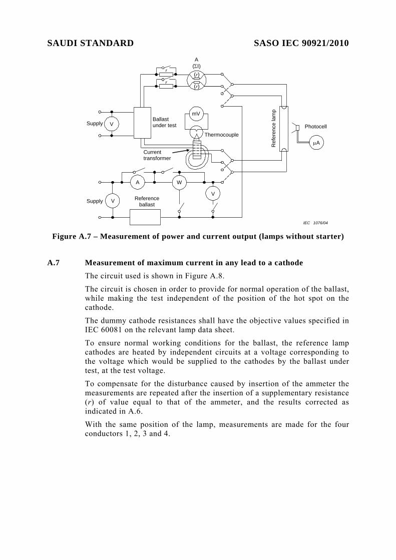
IEC 1076/04 Figure A.7 – Measurement of power and current output (lamps without starter)
A.7 Measurement of maximum current in any lead to a cathode The circuit used is shown in Figure A.8.
The circuit is chosen in order to provide for normal operation of the ballast, while making the test independent of the position of the hot spot on the cathode.
The dummy cathode resistances shall have the objective values specified in IEC 60081 on the relevant lamp data sheet.
To ensure normal working conditions for the ballast, the reference lamp cathodes are heated by independent circuits at a voltage corresponding to the voltage which would be supplied to the cathodes by the ballast under test, at the test voltage.
To compensate for the disturbance caused by insertion of the ammeter the measurements are repeated after the insertion of a supplementary resistance (r) of value equal to that of the ammeter, and the results corrected as indicated in A.6.
With the same position of the lamp, measurements are made for the four conductors 1, 2, 3 and 4.

SAUDI STANDARD SASO IEC 90921/2010
V
A
A
V
Supply
1
2
3
4
RcRc(r)
A
V Supply Supply
Referencelamp
Ballast under test
IEC 1077/04 Figure A.8 – Measurement of maximum current in any lead to a cathode
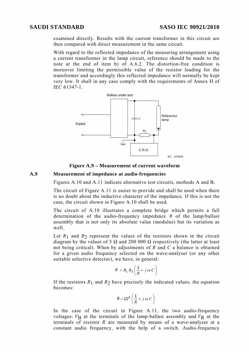
A.8 Measurement of current waveform (Figure A.9)
A.8.1 For lamps operated with starter The peak value of the lamp current is determined by means of a calibrated oscilloscope and the resistor R2 inserted in the earthed side of the circuit.
The capacitor commonly included across the starter switch is replaced by a capacitor C of which the value is 0,01 µF.
Care shall be taken to ensure a sufficiently low impedance of the supply for the different frequencies involved. Moreover the supply voltage distortion of max 3 % (see H.2.3 of IEC 61347-1) shall be taken into account when evaluating test results.
In case of doubt a distortion-free supply shall be used.
A.8.2 For lamps operated without starter Measurements relating to the supply current may be made as in A.8.1.
For measurements relating to the lamp current, the measuring arrangement using a current transformer, described in A.6 is also suitable for determination of the waveform or peak value of the current supplied to the lamp.
A resistor is connected across the secondary winding of the current-transformer or, if purely resistive (e.g. thermocouple), the current measuring device used in A.6 may also serve for this purpose. This resistor is then equivalent to resistor R2 in Figure A.9 and has the measuring instrument connected directly across it. As its value should be kept low, the insertion of an amplifier before the cathode ray oscilloscope may be necessary.
The calibration of the complete arrangement (current transformer, resistor, and oscilloscope) as well as the absence of distortion shall be checked by connecting it with the lamps in a circuit in which the lamp current can be
SAUDI STANDARD SASO IEC 90921/2010
examined directly. Results with the current transformer in this circuit are then compared with direct measurement in the same circuit.
With regard to the reflected impedance of the measuring arrangement using a current transformer in the lamp circuit, reference should be made to the note at the end of item b) of A.6.2. The distortion-free condition is moreover limiting the permissible value of the resistor loading for the transformer and accordingly this reflected impedance will normally be kept very low. It shall in any case comply with the requirements of Annex H of IEC 61347-1.
C
R2
Supply
Ballast under test
C.R.O.
Reference lamp
IEC 1078/04 Figure A.9 – Measurement of current waveform
A.9 Measurement of impedance at audio-frequencies Figures A.10 and A.11 indicate alternative test circuits, methods A and B.
The circuit of Figure A.11 is easier to provide and shall be used when there is no doubt about the inductive character of the impedance. If this is not the case, the circuit shown in Figure A.10 shall be used.
The circuit of A.10 illustrates a complete bridge which permits a full determination of the audio-frequency impedance Z of the lamp/ballast assembly that is not only its absolute value (modulus) but its variation as well.
Let R1 and R2 represent the values of the resistors shown in the circuit diagram by the values of 5 Ω and 200 000 Ω respectively (the latter at least not being critical). When by adjustments of R and C a balance is obtained for a given audio frequency selected on the wave-analyser (or any other suitable selective detector), we have, in general:
Z ⎟⎠⎞
⎜⎝⎛ += Cj
RRR ω1
21
If the resistors R1 and R2 have precisely the indicated values, the equation becomes:
Z ⎟⎠⎞
⎜⎝⎛ += Cj
Rω1106
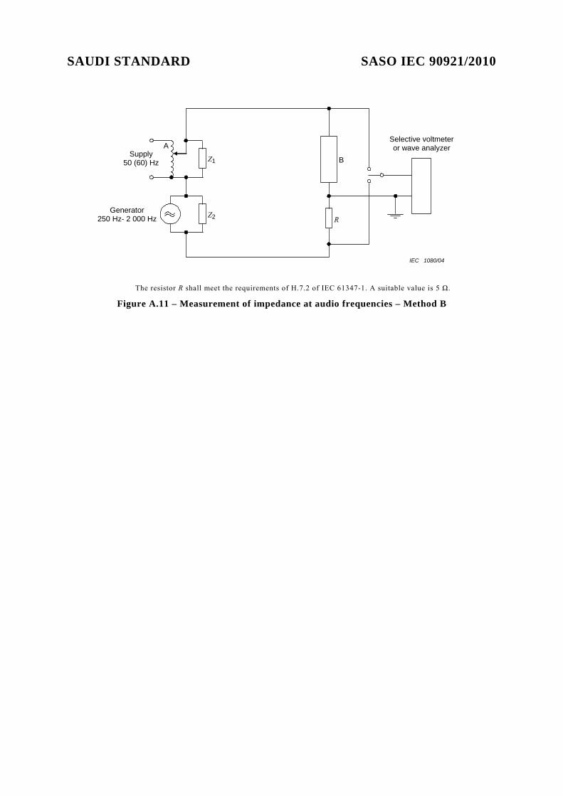
In the case of the circuit in Figure A.11, the two audio-frequency voltages: VB at the terminals of the lamp-ballast assembly and VR at the terminals of resistor R are measured by means of a wave-analyser at a constant audio frequency, with the help of a switch. Audio-frequency

SAUDI STANDARD SASO IEC 90921/2010
impedance Z of the lamp-ballast assembly at the frequency chosen for the measurement is found by the equation:
ZR
B
VVR=
For both circuits:
A = supply transformer 50 (60) Hz
B = lamp-ballast assembly under test Z1 = impedance of value sufficiently high for 50 (60) Hz and sufficiently low for 250 Hz to 2 000 Hz (e.g. resistance 15 Ω + capacitance 16 µF). Z2 = impedance of value sufficiently low for 50 (60) Hz and sufficiently high for 250 Hz to 2 000 Hz (e.g. inductance 20 mH). NOTE The impedance Z1 and/or Z2 are not necessary if the corresponding source has a low internal impedance for the currents of the other.
Supply 50 (60) Hz
Generator 250 Hz- 2 000 Hz Z2
Z1
A
Filter 50 (60) Hz
Selective voltmeter or wave analyzer
C
R
R2 200 000 Ω
R1 5 Ω
B
IEC 1079/04
NOTE The value of 200 000 Ω for one branch of the bridge is not critical.
Figure A.10 – Measurement of impedance at audio-frequencies – Method A
SAUDI STANDARD SASO IEC 90921/2010
Supply 50 (60) Hz
Generator 250 Hz- 2 000 Hz Z2
Z1
A
R
B
Selective voltmeter or wave analyzer
IEC 1080/04
The resistor R shall meet the requirements of H.7.2 of IEC 61347-1. A suitable value is 5 Ω.
Figure A.11 – Measurement of impedance at audio frequencies – Method B
SAUDI STANDARD SASO IEC 90921/2010
Annex B ( informative)
Series operation of two fluorescent lamps
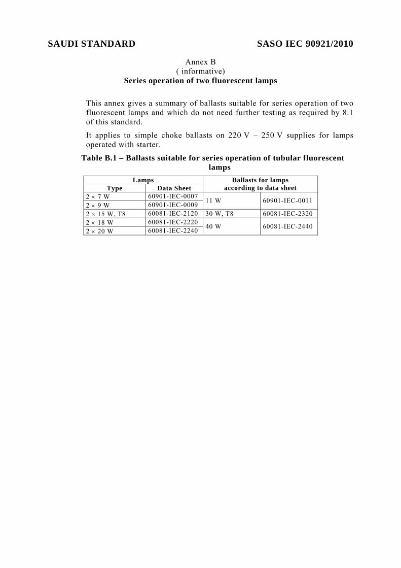
This annex gives a summary of ballasts suitable for series operation of two fluorescent lamps and which do not need further testing as required by 8.1 of this standard.
It applies to simple choke ballasts on 220 V – 250 V supplies for lamps operated with starter.
Table B.1 – Ballasts suitable for series operation of tubular fluorescent lamps
Lamps Type Data Sheet
Ballasts for lamps according to data sheet
2 × 7 W 60901-IEC-0007 2 × 9 W 60901-IEC-0009 11 W 60901-IEC-0011
2 × 15 W, T8 60081-IEC-2120 30 W, T8 60081-IEC-2320 2 × 18 W 60081-IEC-2220 2 × 20 W 60081-IEC-2240 40 W 60081-IEC-2440

SAUDI STANDARD SASO IEC 90921/2010
Annex C (normative)
Reference ballasts
C .1 Marking The reference ballast shall be provided with durable and legible marking as follows:
a) the words “reference ballast” in full,
b) mark of origin; this may take the form of a trade mark, the manufacturer’s name, or the name of the responsible vendor,
c) serial number,
d) rated lamp wattage or lamp designation and calibration current,
e) rated supply voltage and frequency.
C. 2 Design characteristics
C. 2 .1 General design A reference ballast is a self-inductive coil, with or without an additional resistor, designed to give the operating characteristics of clause C.3.
It may be used in a circuit employing a starter or, where applicable, in a circuit including separate power sources to heat the lamp cathodes.
For those types of lamps for starterless circuit where two alternative methods of measurement of electrical and luminous characteristics are specified on the relevant lamp data sheet of IEC 60081, the manufacturer shall state the method to be used.
C. 2.2 Protection The ballast shall be protected, for example by means of a suitable steel case, against magnetic influence, in such a way that its ratio of voltage to current for the calibration current shall not be changed by more than 0,2 % when a 12,5 mm thick plate of ordinary mild steel is placed at 25 mm from any face of the ballast enclosure.
Moreover, the ballast shall be protected against mechanical damage.
C. 3 Operating characteristics Tests shall be carried out in accordance with A.2
C. 3.1 Rated supply voltage and frequency
The rated supply voltage and frequency of a reference ballast shall be in accordance with the values given in IEC 60081 or IEC 60901 on the relevant lamp data sheet.
C. 3 .2 Ratio voltage/current The ratio of voltage to current of a reference ballast shall have the value given in IEC 60081 or IEC 60901 on the relevant lamp data sheet, subject to the following tolerances:
SAUDI STANDARD SASO IEC 90921/2010
a) ±0,5 % at the calibration current value;
b) ±3 % at any other value of current from 50 % to 115 % of the calibration current.
C. 3.3 Power-factor The power-factor of the reference ballast determined at the calibration current shall be as shown in IEC 60081 or IEC 60901 on the relevant lamp data sheet, subject to a tolerance of ±0,005.
C. 3.4 Temperature rise When the reference ballast is operated in an ambient air temperature of between 20 °C and 27 °C, at its calibration current and rated frequency, and after thermal stabilisation, the temperature rise of the ballast winding shall not exceed 25 K, when measured by the “change in resistance” method.
SAUDI STANDARD SASO IEC 90921/2010
Annex D (normative)
Reference lamps
A lamp which has been aged for at least 100 h is considered to be a reference lamp if, when associated with a reference ballast under the conditions as defined in Annex A and operating in an ambient temperature 25 °C unless otherwise specified on the relevant lamp data sheet, the lamp wattage, voltage at lamp terminals or lamp running current do not deviate by more than 2,5 % from the corresponding objective or nominal values, as appropriate, given in IEC 60081. In those cases where lamps are measured in the circuit that provides separate cathode heating (see A.3.2) it is the arc wattage and not the total wattage that should be within 2,5 % of the corresponding value given in IEC 60081. For lamps operated without starter, it is also required that the resistance of the cathodes shall not differ from the objective values for the type of lamp by more than 10 %. If the resistance is higher, it may be reduced by using a shunt resistor. A reference lamp of a type suitable for the ballast under test shall always be used. The waveform of the current passed by a stabilised lamp associated with a reference ballast shall show substantially the same waveform in successive half-cycles. NOTE 1 This limits the possible generation of even harmonics by a rectifying effect.
NOTE 2 For the procedure to be used for the selection of reference lamps, see Article A.3.

SAUDI STANDARD SASO IEC 90921/2010
Bibliography
IEC 60155, Glow starters for fluorescent lamps IEC 60410:1973, Sampling plans and procedures for inspection by attributes IEC 60927, Starting devices (other than glow starters) – Performance requirements IEC 61000-3-2:2000, Electromagnetic compatibility (EMC) – Part 3: Limits – Section 2: Limits for harmonic current emissions (equipment input current equal to or less than 16 A per phase) IEC 61347-2-3, Lamp controlgear – Particular requirements for a.c. supplied electronic ballasts for fluorescent lamps IEC 61547, Equipment for general lighting purposes – EMC immunity requirements