Embed Size (px)
Citation preview

City of Portland Erosion and Sediment Control Manual
Draft
October 2021
Acknowledgments Forthcoming
For More Information Nancy Thorington, Bureau of Development Services

City of Portland i Draft Erosion and Sediment Control Manual—September 2021
Table of Contents List of Appendices ............................................................................................................... iv
List of Figures ...................................................................................................................... iv
List of Tables ....................................................................................................................... iv
Words and Terms ................................................................................................................. v
Chapter 1. Introduction ...................................................................................................... 1
1.1. About the Erosion and Sediment Control Manual ........................................ 1
1.1.1. Where the Erosion and Sediment Control Manual Applies ........................... 1
1.1.2. Erosion and Sediment Control Manual Organization .................................... 1
1.1.3. Future Amendments to the Erosion and Sediment Control Manual............. 2
1.2. Principles of Erosion and Sediment Control ................................................. 2
1.2.1. Erosion Process ................................................................................................ 2
1.2.2. Sedimentation Process.................................................................................... 3 1.2.3. Approaches to Erosion and Sediment Control ............................................... 3
1.2.4. Principles of Soil Management ....................................................................... 4
1.2.5. Economic Impacts of Erosion and Sedimentation ......................................... 5
1.3. Regulatory Framework ................................................................................... 5
1.3.1. Federal and State Regulations........................................................................ 5
1.3.2. City Authority .................................................................................................... 6 1.3.3. Relationship to the Portland Stormwater Management Manual and the Portland Source Control Manual ................................................................................ 6
1.3.4. Other Agencies and Interested Parties ........................................................... 7 1.3.5. Relationship to Oregon Department of Environmental Quality Requirements .............................................................................................................. 7
1.4. Minimum Requirements ................................................................................ 9
Chapter 2. Project Requirements and Processes.............................................................. 13
2.1. Applicability ................................................................................................... 13
2.1.1. Emergencies ................................................................................................... 14 2.1.2. Project Types and Responsibilities ............................................................... 14
2.1.3. Simple Sites ................................................................................................... 16 2.1.4. Special Sites ................................................................................................... 16
2.1.5. Additional Requirements ............................................................................... 17
2.2. Erosion and Sediment Control Professionals ............................................. 17
2.2.1. On-Site Erosion and Sediment Control Manager ......................................... 18
City of Portland ii Draft Erosion and Sediment Control Manual—September 2021
2.3. Erosion, Sediment, and Pollutant Control Plan (ESPCP) ........................... 19
2.3.1. Plan Preparation ............................................................................................ 19
2.3.2. Site and Project Characteristics .................................................................... 19
2.3.3. Plan Requirements ........................................................................................ 20 2.3.4. Project Scheduling ......................................................................................... 22
2.3.5. Sequencing Plan ............................................................................................ 23 2.3.6. ESPCP Review and Approval ......................................................................... 23
2.3.7. ESPCP Revisions ............................................................................................ 24
2.4. Erosion Control Signage ............................................................................... 24
2.5. Site Stabilization ........................................................................................... 25
2.5.1. Temporary Stabilization BMPs ...................................................................... 25 2.5.2. Permanent Stabilization BMPs ..................................................................... 25
2.6. Inspections ................................................................................................... 26
2.6.1. Pre-Construction Meeting .............................................................................. 26 2.6.2. Pre-construction Compliance Inspection ...................................................... 27
2.6.3. Ongoing Maintenance Inspections During Construction ............................. 27
2.6.4. Final Stabilization Compliance Inspection ................................................... 28
2.7. Maintenance ................................................................................................. 28
2.8. Other Reporting and Monitoring Requirements ......................................... 29
2.8.1. Rainfall Monitoring ......................................................................................... 29
2.8.2. Turbidity Monitoring ....................................................................................... 29
2.9. Project Closeout ........................................................................................... 30
2.10. Alternate Materials and Methods ............................................................. 30
2.10.1. On-Property Development Projects ............................................................ 31 2.10.2. Public Works or Capital Improvement Projects within the Public Right-of-Way .............................................................................................................. 31
2.10.3. Capital Improvement Projects in a Public Easement ................................ 31
2.11. Enforcement and Penalties ....................................................................... 32
Chapter 3. Erosion and Sediment Control Best Management Practices (BMPs) ............. 33
3.1. General Principles ........................................................................................ 33
3.2. BMP Selection and Implementation ........................................................... 35
3.3. BMP Applicability and Fact Sheets .............................................................. 37
BMP 3.1: Preserve Natural Vegetation .......................................................... 40
BMP 3.2: Soil Management ............................................................................ 42 BMP 3.3: Surface Roughening ....................................................................... 45
BMP 3.4: Temporary Vegetative Cover .......................................................... 48
City of Portland iii Draft Erosion and Sediment Control Manual—September 2021
BMP 3.5: Mulch ............................................................................................... 56
BMP 3.6: Rolled Erosion Control Products .................................................... 60
BMP 3.7: Plastic Sheeting .............................................................................. 64 BMP 3.8: Armoring .......................................................................................... 67
BMP 3.9: Biotechnical and Soil Bioengineering ............................................ 70 BMP 3.10: Hydroseeding .................................................................................. 75
BMP 3.11: Dust Control .................................................................................... 77
BMP 3.12: Stabilized Construction Access ...................................................... 80 BMP 3.13: Wheel Wash Structures and Equipment ....................................... 84
BMP 3.14: Sidewalk Subgrade Barriers ........................................................... 87 BMP 3.15: Temporary Sediment Control (Silt) Fence ..................................... 90
BMP 3.16: Filtration Bags and Socks ............................................................... 94
BMP 3.17: Fiber Rolls and Wattles................................................................... 97 BMP 3.18: Vegetated Buffers ......................................................................... 100
BMP 3.19: Storm Drain Inlet Protection ......................................................... 103 BMP 3.20: Filtration Berms ............................................................................ 107
BMP 3.21: Diversion Dikes and Swales ......................................................... 110 BMP 3.22: Check Dams .................................................................................. 114
BMP 3.23: Pipe Slope Drains.......................................................................... 122
BMP 3.24: Stormwater Runoff Barriers ......................................................... 126 BMP 3.25: Sediment Traps and Ponds .......................................................... 129
BMP 3.26: Dewatering .................................................................................... 134 BMP 3.27: Permanent Vegetative Stabilization ............................................ 138
BMP 3.28: Non-Vegetative Permanent Stabilization ..................................... 143
BMP 3.29: Turbidity Curtain ............................................................................ 145
3.4. Instream Control Practices ....................................................................... 148
Chapter 4. Pollution Control BMPs ................................................................................. 149
4.1. Construction Site Pollutants ..................................................................... 149
4.2. Trash and Debris Containment and Disposal ......................................... 154
4.3. Hazardous Waste ...................................................................................... 155
Chapter 5. References and Citations .............................................................................. 156
City of Portland iv Draft Erosion and Sediment Control Manual—September 2021
List of Appendices Appendix A Standard Details
Appendix B Recommended Standard Notes
Appendix C Universal Soil Loss Equations
Appendix D Checklists and Logs
Appendix E Simple Site Plan
Appendix F BMP Project Examples
Appendix G Guidance for Projects not Requiring an ESCP
List of Figures Figure 2-1. ESPCP Decision Tree ................................................................................................. 14
Figure 3-1. BMP selection flow chart .......................................................................................... 36
List of Tables Table 3-1. BMP Applicability Guidelines (Minimum and Enhanced BMP Selection) ................ 38
Table 3-2. Grasses and Other Groundcover Plants for Temporary or Permanent Vegetative Cover ........................................................................................................................... 51
Table 3-3. Nuisance Grass Species Not Recommended for Use on Erosion Control or Stormwater Projects or Not Allowed for Use in Environmental Zones ...................................... 54
Table 3-4. Mulch Application Rates and Notes .......................................................................... 58
Table 3-5. Recommended Spacing for Live Fascines1 (measured along the bank face) ........ 62
Table 3-6. Recommended Spacing for Live Fascines1 (measured along the bank face) ........ 73
Table 3-7. Temporary Sediment Control Fence Material Specifications .................................. 92
Table 3-8. Vegetative Buffer Sizing ........................................................................................... 101
Table 3-9. Diversion Dike/Swale Spacing ................................................................................. 111
Table 3-10. Check Dam Spacing ............................................................................................... 118
Table 4-1. Common Construction Site Pollutants .................................................................... 150
City of Portland v Draft Erosion and Sediment Control Manual—September 2021
Words and Terms BDS Bureau of Development Services BES Bureau of Environmental Services BMP Best Management Practice CPESC Certified Professional in Sediment and Erosion Control CASQUA California Association of Stormwater Quality Agencies CWA Clean Water Act ODEQ Oregon Department of Environmental Quality DSL Division of State Lands EPA U.S. Environmental Protection Agency ENB Environment (Built) ESC Erosion and Sediment Control ESPCP Erosion, Sediment, and Pollutant Control Plan fps foot/feet per second Ft. foot/feet Ground Cover
Low-lying vegetation that must be planted and maintained to fully cover the ground surface of an area within 3 years. Mulch does not qualify as ground cover.
lbs./ac pounds per acre Manual Erosion and Sediment Control Manual MS4 Municipal Separate Storm Sewer System NOAA National Oceanic and Atmospheric Administration NPDES National Pollution Discharge Elimination System NRCS Natural Resources Conservation Service OAR Oregon Administrative Rules ODEQ Oregon Department of Environmental Quality ODOT Oregon Department of Transportation ORS Oregon Revised Statute PCC Portland City Code PLS Pure Live Seed Responsible Party
(a) The property owner (b) Any person causing or contributing to a violation of PCC Title 10, Erosion and
Sediment Control RECP Rolled Erosion Control Products SCM Portland Source Control Manual SWMM Portland Stormwater Management Manual sq. square TSS total suspended solids U.S. United States USACE U.S. Army Corps of Engineers USDA U.S. Department of Agriculture

City of Portland 1 Draft Erosion and Sediment Control Manual—September 2021 Chapter 1. Introduction
Chapter 1. Introduction
1.1. About the Erosion and Sediment Control Manual This Erosion and Sediment Control Manual (Manual) provides administrative rules and technical guidance for temporary and permanent erosion prevention, sediment control, and management. It applies to all ground-disturbing activities, including development activities that can cause erosion and mobilization of pollution during the construction process, and for long-term site stabilization. The Manual clarifies the intent of and creates standards to comply with Portland City Code (PCC) Title 10 Erosion and Sediment Control Regulations.
1.1.1. Where the Erosion and Sediment Control Manual Applies PCC Title 10 and this manual apply to all ground-disturbing activities unless such activities are otherwise exempted by PCC. The Manual applies whether an Erosion, Sediment, and Pollutant Control Plan (ESPCP) and inspections are required or not. Further information on when and ESPCP and inspections are required are detailed in Section 2.1.
1.1.2. Erosion and Sediment Control Manual Organization The Manual is organized as follows:
Chapter 1 introduces the necessity, purpose, and principles of erosion and sediment control. Chapter 1 also describes the associated regulatory framework and minimum requirements.
Chapter 2 describes the requirements for different project types and the logistical considerations for implementation of BMPs to satisfy these requirements.
Chapter 3 describes the process and requirements to identify erosion and sediment control BMPs for a development site. Fact sheets are provided for individual BMPs. These fact sheets include an introductory page with key information such as BMP applicability, advantages, and prohibited use cases, as well as more detailed information such as design and material specifications and planning considerations.
Chapter 4 describes pollution control BMPs, including good housekeeping practices and a summary of typical pollutants that may be associated with erosion and development activities.
City of Portland 2 Draft Erosion and Sediment Control Manual—September 2021 Chapter 1. Introduction
1.1.3. Future Amendments to the Erosion and Sediment Control Manual Amendments to the Manual are reviewed and updated through the administrative rulemaking process as delegated to the Bureau of Development Services (BDS) in Section 3.30.045 of the PCC.
However, amendments to Appendices B-G, which are forms or customer service tools used to implement the Manual, may be made without undertaking the administrative rulemaking process. Changes to website links to maintain their validity over time may also be made without undertaking the administrative rulemaking process.
1.2. Principles of Erosion and Sediment Control General site planning and erosion control BMPs are best practices that can be used to prevent discharges from a development site. This manual emphasizes site planning and erosion prevention over structural BMPs to control sediment and pollutant discharge. This emphasis is particularly important in our region immediately before and during large rain events, when it is difficult to establish vegetation and intense rains have high erosion potential.
1.2.1. Erosion Process Erosion is the movement of soil and sediment, mainly by wind and water. Runoff from rain cuts rills and gullies, while wind can strip soil from wide areas. Both types of erosion can move large amounts of sediment, sometimes far from the original site of soil disturbance.
Four main factors influence erosion:
• Soil erodibility: Fine soils, impermeable soils, and soils lacking organic material tend to be more erodible.
• Vegetative cover: Vegetation shields soil from rainfall and wind, increases infiltration, slows runoff velocities, traps pollutants, and retains soil moisture for later plant use between rainstorms. Plant roots increase infiltration and stabilize slopes to prevent erosion during rainstorms.
• Topography: Long, steep slopes increase runoff amounts and velocities and lead to increased erosion.
• Weather: The frequency, intensity, and duration of rainfall influence rates of erosion and sediment release amounts.

City of Portland 3 Draft Erosion and Sediment Control Manual—September 2021 Chapter 1. Introduction
1.2.2. Sedimentation Process Sediment from disturbed soils can move into neighboring properties, streets, drainage systems, and other bodies of water. Excessive sediment is a pollutant and damages the functions of both stormwater sewers and natural watersheds.
While sediments are essential to the development and maintenance of instream habitat, excessive sediment from natural and construction sources pose a substantial danger to the health of fish and other aquatic species. Natural sediments are predominantly silts and clays, whereas construction sediments may contain pollutants, such as pesticides and heavy metals. Sediment resulting from natural processes is usually coarser than construction site silts. Because of their often-finer grained nature and added risk of pollutants, construction site sediments are especially toxic to fish.
The U.S. Environmental Protection Agency estimates that approximately 600 million tons of soil erodes from U.S. construction sites alone each year (1993). The greatest risk of sedimentation and soil loss occurs during the land grubbing, clearing, grading, and excavation phases of development. The NRCS1 reports that between 1992 and 1997, 2.2 million acres of land were developed within the United States. While the development phase of activity poses the greatest risk of soil loss and sedimentation, long term impacts of development activity may occur after development if soils are not properly remediated and stabilized.
1.2.3. Approaches to Erosion and Sediment Control Erosion prevention is the use of practices designed to protect the surface of the soil from the force of rain, wind, mechanical disturbance, and other runoff, so soil particles will not dislodge (erode) and be transported off the site as sediment. These practices include establishing a vegetative cover, preventing stormwater runoff, and/or providing protective covers for exposed soils.
Sediment control is the use of practices designed to capture soil particles after they have been dislodged and become sediment. Sediment control retains sediment onsite through the use of BMPs. Examples of these practices include stabilized construction access points, sediment fencing, sediment traps, or collection ponds.
1 NRCS Urban Soil Primer. https://www.nrcs.usda.gov/Internet/FSE_DOCUMENTS/nrcs142p2_052835.pdf

City of Portland 4 Draft Erosion and Sediment Control Manual—September 2021 Chapter 1. Introduction
Erosion prevention BMPs are more effective than the reactive control of sediment. Once soil particles become dislodged, it requires greater effort and costs to contain the sediment on site. Identifying erosion potential at the planning stage and noting highly erodible areas helps in selecting cost effective, environmentally sensitive erosion prevention BMPs. Additional guidance in selecting erosion prevention and sediment control BMPs is included in Chapter 3.
1.2.4. Principles of Soil Management Soil management practices are intended to protect and restore soil functions, including reducing a soil’s vulnerability to soil erosion (erodibility). These management practices include, but are not limited to, topsoil retention, roughening, soil amendments, de-compaction, and terracing.
Erodibility is a result of various soil characteristics, which can be divided into two groups:
1. Those that influence infiltration and runoff; and
2. Those that affect the resistance to detachment by rainfall and runoff.
Key factors that affect erodibility are soil texture, organic composition, structure, and permeability.
• Surface texture affects how solids erode. Surfaces with ridges and dimples provide a greater amount of roughness and surface area to absorb water, reducing and slowing runoff, and increasing infiltration.
• Organic matter consists of plant and animal litter in various stages of decomposition. Organic matter in soil increases permeability, water holding capacity, and soil fertility, thereby reducing runoff and erosion potential.
• Soil structure is the arrangement of soil particles into aggregates. Loose, granular soils absorb and retain water, whereas compacted soils have decreased capacity to absorb water, increasing erosion potential.
• Soil permeability is a measure of the capacity to allow air and water movement through the soil. Texture, structure, and organic matter all contribute to permeability. Deep soils with high permeability are least subject to erosion from rainfall and sheet flow runoff.
Effective use of soil management practices results in increased soil infiltration, healthier vegetation, a reduction in the need for soil amendments, increased carbon sequestration, and overall ecosystem health during and after construction.
City of Portland 5 Draft Erosion and Sediment Control Manual—September 2021 Chapter 1. Introduction
1.2.5. Economic Impacts of Erosion and Sedimentation Excessive sediment discharge and the lack of proper sediment control can smother instream and near-stream habitat, raise streambeds, alter watercourses, reduce infiltration, and contribute to increased flooding. It can also make water turbid and contribute to degradation of overall water quality, interfering with drinking water sources and recreational uses.
Local governments and their taxpayers face increased costs related to removing sediment from streets, sewers, ditches, sumps, and culverts and dredging sediment from harbors and navigation channels. The implementation of adequate erosion control practices can help reduce or avoid these problems.
1.3. Regulatory Framework
1.3.1. Federal and State Regulations Water pollution in the United States is regulated under the Clean Water Act (CWA) of 1972. In 1987, Congress amended the CWA to include nonpoint sources of pollution. Nonpoint pollution occurs when runoff from land carries pollutants to receiving waters. Section 402 of the CWA provides the legal basis for the National Pollution Discharge Elimination System (NPDES) permit program, which regulates point and nonpoint source discharges.
The U.S. Environmental Protection Agency (EPA) has delegated the implementation of the NPDES program to the state of Oregon. The Oregon Department of Environmental Quality (ODEQ) administers the NPDES program through Oregon Revised Statute (ORS) 468B and associated Oregon Administrative Rules (OAR). ORS 468B.025 explicitly prohibits the discharge or placement of wastes into waters of the state, prohibits the discharge of waste that causes violations of water quality standards, and prohibits violations of permit conditions.
The City must comply with all conditions of its NPDES municipal separate storm sewer system (MS4) Phase I permit and other Federal, State, County, and City regulations or requirements. The City’s NPDES MS4 permit requires implementation of a program to reduce pollutants in stormwater runoff from construction activities. Such programs must require construction site operators to develop erosion prevention and control site plans and implement and maintain effective erosion and sediment control best management practices. In addition to City permit and jurisdictional requirements, ODEQ issues and enforces the State’s NPDES 1200-C permit, applicable to sites greater than 1 acre (see Section 1.3.5).
City of Portland 6 Draft Erosion and Sediment Control Manual—September 2021 Chapter 1. Introduction
Under existing planning and permitting requirements, the responsible party must ensure its actions do not harm or jeopardize threatened or endangered species. In addition, the responsible party must implement conservation BMPs, or reasonable and prudent BMPs identified by the U.S. Fish and Wildlife Services and the National Marine Fisheries Services, to avoid and minimize potential adverse effects to such species.
The responsible party must be aware of, and adhere to, any limitations in the work area imposed by environmental permits such as the Division of State Lands (DSL) and U.S. Army Corps of Engineers (USACE) removal/fill permit.
1.3.2. City Authority This Manual was developed in accordance with the PCC Title 10 Erosion and Sediment Control Regulations. This Manual is a tool to implement Title 10.
Placement and storage of delivered materials are also required to comply with Title 10 and other sections of the PCC that prohibits discharge or deposition of sediment on streets or into sewers, specifically PCC Chapter 17.38, Drainage and Water Quality, and PCC Chapter 17.39, Storm System Discharges.
1.3.3. Relationship to the Portland Stormwater Management Manual and the Portland Source Control Manual Two other City manuals, the Stormwater Management Manual (SWMM) and the Source Control Manual (SCM), work in tandem with this manual to comply with the City’s NPDES MS4 permit. The Bureau of Development Services (BDS) is responsible for maintenance and implementation of this Manual. The SWMM and the SCM are under the authority of the Bureau of Environmental Services (BES). Together, this Manual, the SWMM and the SCM describe City requirements to protect the environment, City assets, and the public.
The SWMM provides post-construction stormwater management policy and design requirements for structural stormwater facilities addressing infiltration, discharge, pollution reduction, and flow and volume control standards. Implementing requirements of the SWMM helps to protect water resources and conserve the existing and future conveyance capacity of storm sewers and combined sewers in Portland.
Some site characteristics, activities, and uses on property may generate or mobilize specific pollutants of concern or levels of pollution. The SCM requires the implementation of best management practices and structural source controls to

City of Portland 7 Draft Erosion and Sediment Control Manual—September 2021 Chapter 1. Introduction
manage pollutants at their source for types of site characteristics, activities and uses. The SCM also includes requirements for construction dewatering and soil management for sites with known or suspected contamination.
The content of these three manuals may overlap while addressing different aspects of stormwater management. Responsible parties must reference all manuals to determine the appropriate standards that apply to a project or site.
1.3.4. Other Agencies and Interested Parties Projects and development activities within the City of Portland are subject to other regulations, requirements, and permits, beyond the scope of this Manual. This Manual does not incorporate or address all regulatory requirements potentially applicable to a project or site and, therefore, does not eliminate the need to comply with other applicable local, state, and federal regulatory requirements. This Manual supplements but does not replace other local, state, and federal requirements and technical standards. Other requirements and standards may conflict with requirements of this Manual. It is the responsibility of the site or permit applicant to contact the City to resolve potential conflicts between the requirements.
Responsible parties must identify and comply with all applicable local, state, and federal regulations and requirements. During the planning process, the responsible party must coordinate meetings with private groups, public agencies, or jurisdictions that may either have an interest in, or control of the impacts of, proposed development or activities. This process provides a means for other interested parties to supply input regarding erosion and sediment controls, sites with contamination, environmentally sensitive areas, sites that require tree preservation, and other regulated activities.
1.3.5. Relationship to Oregon Department of Environmental Quality Requirements
1.3.5.1. 1200-C Permits The ODEQ 1200-C Permit is required if the following activities have the potential to discharge to surface waters or to a conveyance system that leads to surface waters of the state in Oregon and do not have coverage under another NPDES permit:
• Any construction activity and materials or equipment staging and stockpiling that will disturb one or more acres of land.

City of Portland 8 Draft Erosion and Sediment Control Manual—September 2021 Chapter 1. Introduction
• Any construction activity and materials or equipment staging and stockpiling that will disturb less than one acre of land but is part of a common plan of development or sale that will ultimately disturb one or more acres of land.
• Any construction activity that results in the disturbance of less than one acre of land that is a necessary and required component (e.g., utilities, structure, or infrastructure) of a final project that will ultimately disturb one or more acres of land.
• Any construction activity that may discharge stormwater to surface waters of the state that may be a significant contributor of pollutants to waters of the state or may cause an exceedance of a water quality standard.
The City of Portland is not an ODEQ 1200-CN jurisdiction; therefore, it is the site operator’s responsibility to obtain 1200-C permit coverage directly from ODEQ. For sites that require 1200-C coverage, site operators must adhere to the following:
• Prior to BDS’ Erosion Control Review approval, for projects on private property that have one acre or more of ground disturbing activities, the applicant must demonstrate that the ODEQ 1200-C permit has been issued or provide documentation from ODEQ that the permit is not required.
• For sites that have less than 1 acre of ground disturbance but are part of a Larger Common Plan of Development, BDS does not verify or require verification that the site has obtained 1200-C coverage. BDS recommends that the applicant contact ODEQ to confirm 1200-C permit coverage requirements prior to applying for City of Portland permits.
• For public property or capital improvement projects, the responsible City bureau or contractor is required to develop the ESPCP and obtain the 1200-C permit prior to starting work.
– To avoid confusion, project stoppages, and possible enforcement actions from state regulatory agencies, it is strongly recommended that the 1200-C permit be obtained prior to permit application.
– To avoid conflicts or confusion, the ESPCP submitted to the City of Portland must be consistent with the DEQ-approved ESPCP.
– The principals, standards, and BMPs outlined in this Manual are intended to provide the user with relevant guidance related to the City’s erosion and sediment control requirements. However, the Manual may not reflect all performance, monitoring, and operational standards required by the ODEQ 1200-C permit. It is the responsibility of the site operator to
City of Portland 9 Draft Erosion and Sediment Control Manual—September 2021 Chapter 1. Introduction
design and implement an ESPCP that complies with both ODEQ and City of Portland requirements.
1.3.5.2. Contaminated Media Plans Sites with known contamination may already have a Contaminated Media Plan that includes erosion and sediment control BMPs developed for the site and based on work already completed under ODEQ Cleanup Program direction. This plan will likely identify the area and extent of existing contamination and include procedures for soil management related to the contaminants on property. The Contaminated Media Plan may be submitted with the permit application for reference.
• To avoid conflicts or confusion, the ESPCP submitted to the City of Portland must be consistent with any required ODEQ Contaminated Media Plan.
• The principals, standards, and BMPs outlined in this Manual are intended to provide the user with relevant guidance related to the City’s erosion and sediment control requirements. However, the Manual may not reflect all performance, monitoring, and operational standards required by an ODEQ Contaminated Media Plan. It is the responsibility of the site operator to design and implement an ESPCP that complies with both an ODEQ Contaminated Media Plan and City of Portland requirements.
1.4. Minimum Requirements PCC Title 10 and this Manual apply to all ground disturbing activities in the City of Portland, regardless of whether a permit is required, unless such activities are otherwise exempted by Portland City Code. The requirements for erosion prevention and sediment control include the following three items:
1. Visible and measurable sediment or pollutant exiting the site, entering the public right-of-way, or depositing into any water body or storm sewer and drainage system is prohibited.
2. Depositing or washing soil into a water body or the storm sewer and drainage system is prohibited.
3. Ground-disturbing activities requiring a permit must provide adequate public notification of the City’s Erosion Control Complaint Hotline.

City of Portland 10 Draft Erosion and Sediment Control Manual—September 2021 Chapter 1. Introduction
To achieve these performance standards, parties responsible for ground disturbing activities within the City must comply with the following minimum requirements:
1. Install BMPs to keep soil on site and out of water bodies, adjacent property, storm sewer and drainage systems, or the public right-of-way as the first step in any development. These BMPs must be made functional prior to any upslope development taking place.
2. Protect stormwater inlets that are functioning during development by applying approved sediment control BMPs so that sediment-laden water cannot enter the inlets without first being filtered.
3. Post signage on the site of the permitted ground-disturbing activity that identifies the site’s permit number and address and the City’s Erosion Control Complaint Hotline number or the responsible City project manager or inspector. Ground-disturbing activities that do not require a permit (such as agriculture) are exempted from this requirement. (See Section 2.4 for detailed signage requirements.)
4. Implement appropriate BMPs from this manual. See Chapter 3.
5. Implement General Controls/Housekeeping BMPs. See Chapter 4.
6. Promptly remove any soil, sediment, and pollutants that enter the public right-of-way and implement BMPs to prevent sedimentation in the right-of-way.
7. Apply permanent or temporary soil stabilization to denuded development site areas in conformance with the following requirements:
– Between October 1 and April 30, all denuded sites must be provided with either temporary or permanent soil stabilization as soon as practicable, but in no case more than two days after ground-disturbing activity occurs.
– Between May 1 and September 30, temporary erosion and sediment control BMPs to reduce dust and sediment transport must be applied as soon as practicable, but in no case more than seven days after ground-disturbing activity occurs.
8. Groundcover must be installed on any portion of a site that is denuded for more than 6 months. Sports fields or playgrounds surrounded by vegetative cover or permanently installed curbing are exempt from this requirement.

City of Portland 11 Draft Erosion and Sediment Control Manual—September 2021 Chapter 1. Introduction
9. Temporary erosion and sediment control BMPs must be maintained until permanent erosion and sediment control BMPs are established.
10. All exposed soil must be covered by permanent stabilization BMPs allowed by this Manual, structures, or paving prior to project completion.
11. Ground-disturbing activity is prohibited between October 1 and April 30 in the Balch Creek and Forest Park subdistricts of the Northwest Hills plan district and is not subject to administrative review per Section 10.40.040. See Chapter 33.563 of the City of Portland Zoning Code.
12. Apply replacement vegetative cover that does not include plants listed in the Nuisance Plants List, as set forth in the City of Portland Plant List (2016) or more recent. Ground-disturbing activities that do not require a permit (such as agriculture) are exempted from this requirement.
13. Secure or protect soil stockpiles throughout the project with temporary or permanent soil stabilization BMPs. The responsible party is accountable for the protection of all stockpiles on the site and those transported from the site. Stockpiles of soil may be subject to additional regulations requiring permit, review, or erosion and sediment control.


City of Portland 13 Draft Erosion and Sediment Control Manual—September 2021 Chapter 2. Project Requirements and Processes
Chapter 2. Project Requirements and Processes
2.1. Applicability The requirements of PCC Title 10 and this Manual apply to all ground-disturbing activities, unless such activities are otherwise exempted by PCC Title 10. Certain activities are required to obtain a development permit with an erosion, sediment, and pollution control plan (ESPCP) and are subject to City inspections. Activities that do not require a permit are still required to meet the erosion control requirements of this Manual. Erosion and sediment control BMPs are required during all ground-disturbing activity from initial clearing until permanent site stabilization BMPs are in place.
An approved ESPCP is required prior to ground disturbing activity, and inspections during and immediately after construction are required whenever ground disturbance is 500 sq. ft. or greater in area; OR where a site is a Special Site as stated in PCC Title 10 and defined in Subsection 2.1.4 of this Manual.
Some activities that do not require an ESPCP and inspections must still comply with the requirements of this Manual to reduce the risk of erosion or pollutant and sediment discharge. Some examples of activities that do not require a permit include landscaping and lawn maintenance, mulch and soil delivery, installation of retaining walls under four feet in height, and some clearing and grubbing activities.
Figure 2-1 provides a basic framework to understand when the elements of this Manual apply.

City of Portland 14 Draft Erosion and Sediment Control Manual—September 2021 Chapter 2. Project Requirements and Processes
Figure 2-1. ESPCP Decision Tree
2.1.1. Emergencies Emergency work necessary to mitigate a hazard that poses imminent danger to life or property (such as substantial fire hazards, risk of flood, landslides, or other emergency) may commence without complying with the requirements during the period of the emergency. However, upon a determination by the Director that such hazard has passed, the provisions of Title 10 apply.
2.1.2. Project Types and Responsibilities PCC Title 10 and this Manual apply to a wide variety of project types. Within the City of Portland, different City agencies have responsibility for ESPCP review, inspection, and enforcement of PCC Title 10 and this Manual. Typical project types, permitting process, and the lead agencies responsible for implementing PCC Title 10 and this Manual are described below. In all cases, enforcement actions may extend to other bureaus or outside agencies, depending on the nature of the violation.

City of Portland 15 Draft Erosion and Sediment Control Manual—September 2021 Chapter 2. Project Requirements and Processes
2.1.2.1. On-Property Development Permits Development activity that occurs outside the public right-of-way is considered “on- property”. The property can be publicly or privately owned. Multiple development permit types are associated with on-property projects, including, but not limited to, Residential Building Permits, Commercial Building Permits, Site Development Permits, Development Review Permits, and Zoning Permits. Examples of on-property projects include clearing, grading, excavation, landscaping, and non-soil pollutant generating activities. For on-property projects, BDS is responsible for the ESPCP review, conducting City inspections during construction, and potential enforcement actions. The responsible party is responsible for installing, inspecting, maintaining, and adjusting BMPs during construction
2.1.2.2. Capital Improvement Projects in the Public Right-of-Way or in a Public Easement Capital improvement projects are those initiated by the City to construct and include utility improvements, linear roadway improvements, trails, parks projects, or construction of City facilities. For capital improvement projects within the public right-of-way, or in a public easement, the project lead City bureau is responsible for ESPCP review, conducting City inspections during construction, and potential enforcement actions. The City crew or contractor hired by the City is responsible for installing, inspecting, maintaining, and adjusting BMPs during construction.
2.1.2.3. Public Works Permits A public works permit is a permit obtained by a private or public party for construction activities in the public right-of-way. Public works permits are typically needed for street improvements, frontage improvements, driveway connections, utility extensions, and other activities to address conditions of approval for an on-property development permit application. Separate permits are issued for both the on-property work and the associated work in the public right-of-way.
For public works permits, the City’s Public Works group is responsible for ESPCP review, conducting City inspections during construction, and potential enforcement actions. The responsible party is responsible for installing, inspecting, maintaining, and adjusting BMPs during construction.
2.1.2.4. Activities that do not Require a City Development Permit Projects that do not require a development permit are still required to implement erosion and sediment control practices to meet minimum performance BMPs (see Section 1.4).
City of Portland 16 Draft Erosion and Sediment Control Manual—September 2021 Chapter 2. Project Requirements and Processes
For ground disturbing activities that do not require a development permit, the private responsible party or lead City bureau is responsible for installing, inspecting, maintaining, and adjusting BMPs during construction to limit erosion, reduce sediment transport, and prevent track-out from the project site. The Portland Bureau of Environmental Services (BES) is responsible for enforcement actions related to activities that do not require a development permit.
2.1.3. Simple Sites Sites with a lower potential for erosion and sediment discharge are considered “Simple Sites,” and applicants may submit an ESPCP through a streamlined application process. Sites that meet ALL the following conditions are considered Simple Sites and may use the City’s Simple Site Plan as the ESPCP (see Appendix E):
• Flat (less than 10 percent slope before development)
• Less than 10,000 sq. ft. of ground disturbance
• More than 50 feet from a wetland or waterbody
• Not a land division of 10,000 sq. ft. or more
• Outside of Environmental, River, or Greenway overlay zones
While simple sites are not required to submit an ESPCP as part of the permitting application process, the minimum requirements of Section 1.4 still apply. BMPs identified on the Simple Site Plan require ongoing implementation, inspection, maintenance, review, and update, like the ESPCP (see Section 2.3.7). Simple sites must identify an ESC Manager (see Section 2.2.2) who will be responsible to comply with the requirements in this Manual.
2.1.4. Special Sites Special site conditions may present additional challenges with PCC 10.30.020, and the Director may require additional erosion, sediment, and pollution control BMPs. Sites with any one of the following conditions are considered Special Sites and require an ESPCP, regardless of the extent of the ground disturbing activity:
• Slopes before development that are greater than 10 percent
• Ground disturbance of a natural vegetative buffer within 50 feet of a wetland and/or water body
• Sites located entirely or partially within an Environmental, River, or Greenway Overlay Zone

City of Portland 17 Draft Erosion and Sediment Control Manual—September 2021 Chapter 2. Project Requirements and Processes
• Sites or a development phase with ground disturbance at any one time of 10,000 sq. ft. or more (single family dwellings and duplex dwellings are exempt from this size limitation)
• Development includes a land division containing 10,000 sq. ft. or more
• Project timing is such that ground-disturbing activity will take place between October 1 and April 30
• Development will have ground disturbance on a site with known contamination
• Development involves discharge or offsite disposal of dewatering or trench spoils
2.1.5. Additional Requirements Additional requirements not detailed in this Manual may be imposed by the Director to achieve compliance with PCC 10.30.020. Such activities may include, but are not limited to, the following:
• Requiring drainage control in compliance with Titles 17 and 24, during all development phases
• Requiring that a State of Oregon registered professional engineer, other professional certified by the State of Oregon with experience or qualifications in preparing erosion control plans, or a Certified Professional in Sediment and Erosion Control (CPESC) prepare and implement the ESPCP
• Prohibiting ground-disturbing activities between October 1 and April 30
• Limiting the amount of denuded soil at any given time
• Requiring a bond, letter of credit, or other guarantee
2.2. Erosion and Sediment Control Professionals All erosion and sediment controls must be developed by a qualified professional. The qualified professional must develop an ESPCP based upon information obtained from local and regional agencies and a detailed field site visit. The plan must consider site areas that may be susceptible to erosion and sediment deposits, be based on design objectives, consider alternatives, and specify selected BMPs.
Approval of the ESPCP does not relieve the applicant’s responsibility to ensure that BMPs are installed, updated, and maintained to prevent sediment from leaving the construction site.
City of Portland 18 Draft Erosion and Sediment Control Manual—September 2021 Chapter 2. Project Requirements and Processes
2.2.1. On-Site Erosion and Sediment Control Manager The responsible party must designate an On-site Erosion and Sediment Control Manager (ESC Manager) to conduct inspections of erosion sediment and pollutant control BMPs during all phases of development activities. The ESC Manager is responsible for ensuring the implementation of the ESPCP and has the authority to immediately mobilize necessary personnel and equipment to correct, modify and add BMPs when necessary.
Duties of the ESC Manager include:
• Provide name and 24-hour contact information on the ESPCP.
• Manage and ensure proper implementation the ESPCP.
• Accompany public agency inspectors during compliance inspections before construction, during construction, and at project close-out.
• Conduct or oversee documented inspections during construction (Section 2.6.1).
• Make immediate repairs to the BMPs or install additional BMPs to address erosion and sediment control concerns.
• Document erosion control inspection results and resulting adjustments or changes after each inspection.
• Document or assign documentation of inspections and maintain an up-to-date ESPCP log throughout the life of the project, available for review upon request.
• Prepare a contingency plan for emergencies during the rainy season.
For 1200-C permits, ODEQ will require that the ESC Manager have appropriate training and experience in accordance with state permit requirements and are responsible for monitoring and keeping records of site conditions as they relate to erosion and sediment control.

City of Portland 19 Draft Erosion and Sediment Control Manual—September 2021 Chapter 2. Project Requirements and Processes
2.3. Erosion, Sediment, and Pollutant Control Plan (ESPCP) An ESPCP is required for any ground-disturbing activity that requires a City of Portland building, public works, or development permit (PCC 10.40). In addition, an ESPCP may be required for sites with qualifying special site conditions, including being on steep slopes, in Environmental, River, or Greenway overlay zones, or in response to a violation of the City’s erosion control requirements (see Section 2.1.4 for additional information). Sites that meet ALL conditions of a Simple Site as described in Section 2.1.3 may use the City’s Simple Site Plan as the ESPCP (see Appendix E).
An ESPCP is a detailed description of where and how activities will be implemented to control erosion, sediment, and pollutants on a development site. The ESPCP is a central, specific component of the overall site development management plan. The ultimate goal of erosion prevention is to limit the time and area of ground disturbance, keep pollutants separate from stormwater runoff, and establish permanent groundcover as quickly and thoroughly as possible.
Approval of the ESPCP does not relieve the responsible party’s responsibility to ensure that erosion prevention and sediment control BMPs are installed and maintained to prevent sediment from leaving the construction site.
2.3.1. Plan Preparation ESPCPs must be developed by a professional knowledgeable in erosion and sediment control. The responsible party must designate an individual to be responsible for onsite installation, maintenance, and removal of BMPs. The ESPCP must be submitted and approved by the City prior to any ground disturbance.
A State of Oregon registered professional engineer, other professional certified by the State of Oregon with experience or qualifications in preparing erosion control plans, or a registered CPESC may be required to prepare the ESPCP for special sites or when a major plan revision is required because of site violations.
2.3.2. Site and Project Characteristics Before developing the ESPCP, review/identification of site characteristics is required, including:
• Total disturbance area. If the site is larger than one acre, the project will also need a 1200-C permit from ODEQ.

City of Portland 20 Draft Erosion and Sediment Control Manual—September 2021 Chapter 2. Project Requirements and Processes
• Adjacent streambanks, waterways, and other natural resources. Consult with appropriate local, state, and federal agencies before developing the ESPCP. There may also be restrictions on when you can carry out in-water work or work adjacent to natural resources.
• Site topography. Look for ways to clear the area along the elevation contours, which can reduce erosion. If there are steep slopes, consider which BMPs will be effective in controlling stormwater runoff, protecting slopes from erosion, and avoiding cutting of channels and rills.
• Wetlands, water bodies, or other protected areas (such as Environmental, River and Greenway Zones). Show them clearly on plans and prepare to protect them as no-disturbance areas with construction fencing in the field.
• Existing trees to be preserved and tree root protection areas. Erosion and sediment control BMPs must remain outside of the tree root protection areas or be approved as part of the tree preservation plan required by Title 33 or Title 11, as applicable.
• Site soil characteristics. Different soils have different erodibility and infiltration characteristics. Consider how the soils may affect the performance of your site BMPs. Use the Revised Universal Soil Loss Equations in Appendix C of this Manual, and the Portland SWMM to determine erodibility and infiltration characteristics, respectively.
• Areas of contamination.
• Groundwater seepage areas onsite.
• Identify pollution-generating activities (concrete washout, vehicle fueling or maintenance, dewatering, painting) associated with construction.
• Identify materials to be stored onsite during construction.
2.3.3. Plan Requirements The ESPCP includes both visual and narrative elements. The visual elements must be depicted on a construction plan sheet, consistent with the larger land use application or permit submittals for the project. The level of detail for the narrative elements must be consistent with the size and scope of the proposed project. For small non-complex sites, construction notes on the plan sheet are sufficient narrative. Larger or more complex projects may require a more extensive narrative and/or phased plans.
City of Portland 21 Draft Erosion and Sediment Control Manual—September 2021 Chapter 2. Project Requirements and Processes
The ESPCP must :
• Indicate the name and address of all responsible parties, including the developer and property owner.
• Identify an emergency contact and telephone number.
• Identify any wetland, water body, or outfalls within 200 feet of the ground-disturbing activity. Indicate any wetland, water body, or other receiving water to which the site directly discharges, regardless of distance.
• Identify the type of system that receives runoff for the project site (e.g., combined storm sewer, open channels, etc.).
• Provide a simplified narrative description of existing land uses and proposed land use. Provide a copy of any applicable land use review documents.
• Provide clear delineation and approximate size of the area to be disturbed. Identify efforts to minimize area of disturbance. Disturbance areas must be realistic for the scope of work and include construction support areas such as onsite staging areas, offsite storage areas, haul/access/support roads, stockpile areas, borrow pits, etc.
• Show existing and proposed ground contours and drainage patterns. In addition, provide drainage patterns for all intermediate contours throughout the length of the ground-disturbing activity. Show drainage controls that will be used prior to installation of a final stormwater conveyance system.
• Identify any known or suspected soil contamination. Refer to the Portland SCM for how to identify contamination.
• Provide a preliminary activity schedule (see Section 2.3.4).
• Identify planning-level BMPs such as speed limits on interior roads.
• Show the location of all erosion, sediment, and pollution control BMPs and their position in relation to ground-disturbing activities. Identify which BMPs, if any, are planned for permanent stormwater controls. Note, permanent stormwater management facilities must comply with the Portland SWMM.
• Identify development activities/areas with the potential to generate non-stormwater pollutants, such as vehicle maintenance, fueling, trash and debris collection, dewatering discharge, and material stockpiles. Dewatering is subject to the requirements of this Manual and the Portland SCM.

City of Portland 22 Draft Erosion and Sediment Control Manual—September 2021 Chapter 2. Project Requirements and Processes
• Identify construction staging areas, materials storage, and stockpile areas. Note whether any of these activities will occur offsite.
• Indicate on the site plan all areas of non-disturbance and/or retention of existing vegetation, including each tree to be preserved and the associated tree root protection zone.
• Provide a plan and schedule for temporary and permanent site stabilization BMPs (see Section 2.5).
• Use a combination of BMP types. Identify BMPs for site entry and exit, erosion prevention, sediment control, dust control, and site stabilization (see Chapter 3).
• For any structural BMPs, provide a detail of installation methods, including any sizing calculations (flow volumes, rates, etc.) or reference to BMPs outlined in this Manual.
• Describe site inspection requirements for all BMPs, including regular frequency and special circumstances like high rain events.
• Describe site maintenance requirements for all BMPs, including regular frequency and special circumstances like high rain events, and methods used.
• When required by the Director, provide drainage calculations.
• Show compliance with all special requirements mandated by the Director.
• Always remain on-site and available from initial clearing through permanent stabilization and final inspection.
2.3.4. Project Scheduling Thoughtful project scheduling can support erosion control BMPs and avoid potential problems. The larger the site, the more important it becomes to consider erosion and sediment control as a separate element shaping the project’s construction sequencing.
The project schedules must include anticipated start and completion dates for all sequencing of ground-disturbing activity and the associated dates for installation of erosion, sediment, and pollution control BMPs. The activity schedule must also indicate the timeframe for installation, maintenance, and removal of temporary BMPs.
The applicant is responsible for notifying the City when site work will deviate from the preliminary schedule. The preliminary schedule can be modified through the
City of Portland 23 Draft Erosion and Sediment Control Manual—September 2021 Chapter 2. Project Requirements and Processes
designated City site inspector as work on the site progresses. The City site inspector may determine that a formal review of plan revision is required.
2.3.5. Sequencing Plan Larger projects benefit from the development of a Sequencing Plan to stagger ground disturbing activities. Thoughtful phasing and sequencing of construction activities limits the amount of soil exposed at any one time. This reduces the likelihood of soil to wash off of the site and onto streets, drainage systems, and adjacent properties. In addition, staggering the ground disturbing activities can reduce the number and size of erosion prevention BMPs required as well as the cost and effort to maintain sediment control facilities. Limiting the disturbance area may also allow topsoil to be stockpiled on site, making revegetation and landscaping easier to establish.
In developing the sequencing plan, analyze the site and the anticipated construction schedule for the various aspects of the site, including the need for clearing, grubbing, grading, utility installation, structural improvements, and landscaping. Consider such factors as time of year, anticipated weather, activity duration, and how to minimize the area of soil exposed at any one time. Considering the time of year and area of soil exposure, identify activities that create a high risk for soil movement by air or by water.
Important factors that may influence the sequencing plan include:
• Existing site conditions
• Site entry and staging of materials and equipment
• Drainage, road, and utility installation
• BMPs identified for onsite and perimeter erosion and sediment control
• Opportunities for material reuse and recycling
• Need for waste storage and disposal
2.3.6. ESPCP Review and Approval The Director may require a pre-application conference with the responsible party to review the erosion, sediment, and pollution control requirements and procedures. The Director may deny a plan if it is determined that the plan does not meet the requirements of Title 10 and this Manual.
City of Portland 24 Draft Erosion and Sediment Control Manual—September 2021 Chapter 2. Project Requirements and Processes
Review and approval of the ESPCP is based on meeting the minimum requirements outlined in Section 1.3, in accordance with the anticipated site conditions and schedule. Approval of a plan may be granted with or without restrictions.
Restrictions on a plan may include, but are not limited to, the following:
• Work is conducted only during a specified time of the year.
• Only a portion of the work is approved.
• Oversight by an erosion control professional is mandated.
2.3.7. ESPCP Revisions The ESPCP is an anticipated set of actions and BMPs that the designer believes will meet the erosion and sediment control performance standards outlined in PCC Title 10. Construction activities, environmental factors, and other influences may change the site conditions from what was anticipated during the design of the ESPCP. As such the responsible party is responsible for adjusting BMPs and revising the ESPCP during construction to meet performance standards.
When changes are made to BMPs during construction, revisions to the ESPCP are required. In some cases, the revision may be made on-site by marking up issued plans; in other cases, a revision must be documented by submitting the revised plans for formal review and permit revision, at the discretion of the City inspector.
In either case, the ESC Manager must initiate an on-site revision immediately upon identifying the need to adjust or revise BMPs. The ESC Manager must document the changes on the inspection report, noting the change in site conditions or any problems with the installed BMPs. Any removal or addition of BMPs must be reflected on the approved ESPCP drawings. The revised drawing is required to be on-site and made available to the City inspector upon request. Requiring a formal plan review and permit revision will be at the discretion of the City inspector.
2.4. Erosion Control Signage Post signage at the site of the permitted ground-disturbing activity. Signage must identify the City’s Erosion Control Complaint Hotline number or, in the case of public projects, the responsible City project manager or inspector. Ground-disturbing activities that do not require a permit (such as agriculture) are exempted from this requirement.
Additional signage requirements are as follows:
City of Portland 25 Draft Erosion and Sediment Control Manual—September 2021 Chapter 2. Project Requirements and Processes
• Post signage where it is clearly visible from the right-of-way. The sign must be at least 2 feet by 3 feet and made of materials that will withstand weather for the duration of the project. Lettering must be at least 3 inches high and easily readable.
• Another visual notification method may be used if approved by the Director of the designated enforcing bureau.
2.5. Site Stabilization Site stabilization is the method of stabilizing exposed soil during and after construction to prevent erosion. Site stabilization also aids with dust control.
Temporary stabilization BMPs are installed and maintained prior to and during construction to provide short-term stabilization between construction activities. Permanent stabilization BMPs are the long-term BMPs planned for the site. Permanent stabilization BMPs must be installed immediately following final grading, so that the materials have time to take root or otherwise stabilize the soil prior to project close-out.
2.5.1. Temporary Stabilization BMPs Temporary stabilization BMPs are used to cover exposed soil during construction, as required to reduce the potential of soil erosion during construction. Temporary stabilization BMPs must remain in place throughout the duration of a project, including during permanent stabilization efforts.
2.5.2. Permanent Stabilization BMPs Prior to project completion, all areas of ground disturbance must be stabilized with BMPs suitable for permanent stabilization, structures, or paving. Permanent stabilization BMPs must provide for full coverage of site soils and may be vegetative or non-vegetative. BMPs must be in place and functioning at the time of final project inspection and close out. For example, if hydroseeding is selected as the permanent stabilization BMP, the seed must have germinated and developed into a full stand prior to final project inspection. Therefore, permanent stabilization must be installed as soon as grading is complete to meet inspection timelines, rather than as a final project step.
BMPs that may be used for permanent stabilization include:
• BMP 3.27: Permanent Vegetative Stabilization
City of Portland 26 Draft Erosion and Sediment Control Manual—September 2021 Chapter 2. Project Requirements and Processes
• BMP 3.10: Hydroseeding
• BMP 3.5: Mulch (for select applications)
• BMP 3.28: Non-Vegetative Permanent Stabilization
Site conditions and constraints will inform selection of permanent stabilization BMPs.
2.6. Inspections Inspection and maintenance of erosion and sediment control BMPs are required to ensure their performance throughout construction. BMPs must be properly installed, inspected, and maintained and adjusted as necessary.
Typical inspections during a project include the pre-construction inspection, inspections during construction by both City staff and the on-site ESC Manager, and a final inspection to verify permanent stabilization is in place. The approved ESPCP must always be on-site and accessible to the on-site ESC Manager and City inspectors. The checklists in Appendix D provide additional guidance for preparing for and conducting inspections.
2.6.1. Pre-Construction Meeting Some larger commercial projects require a pre-construction meeting between the responsible party and City inspectors. The pre-construction meeting provides an opportunity for the ESC Manager to discuss the ESPCP with the City inspector and identify elements of the ESPCP that require the most attention. ESPCP adjustments to improve BMP performance or make installation easier/maintenance more reliable may also be discussed.
The pre-construction meeting is also an opportunity to discuss the inspection schedule and procedures. Key points to consider in the pre-construction meeting are:
• Methods to document onsite inspections, maintenance actions, and ESPCP revisions.
• Adjacent areas that need special protection from sedimentation, particularly environmentally sensitive areas such as wetlands, stream crossings, channel, and water disposal outlets.
• Location of erosion and sediment control BMPs and their installation and maintenance.

City of Portland 27 Draft Erosion and Sediment Control Manual—September 2021 Chapter 2. Project Requirements and Processes
• Sequence of installation with respect to the construction schedule.
• Temporary and permanent site stabilization BMPs.
• Construction schedule and any anticipated shutdown periods.
• Location of staging and disposal areas.
• Emergency or contingency plans.
• Any special requirements identified in permits.
2.6.2. Pre-construction Compliance Inspection For on-property development permits, an initial erosion and sediment control inspection by the City is required after permit issuance. All BMPs must be installed in accordance with the issued permit. This inspection must be approved prior to any ground disturbing activity.
2.6.3. Ongoing Maintenance Inspections During Construction The City will conduct regular compliance inspections to review erosion and sediment control BMPs and records during construction. City inspectors have the authority to require immediate maintenance, removal, or adjustment of BMPs to address identified deficiencies. Failure to control sediment or pollutants is cause for the City to engage in enforcement actions in accordance with Section 2.11.
In addition, the onsite ESC Manager must conduct or oversee regular inspections of erosion and sediment control BMPs throughout the construction process.
2.6.3.1. Frequency of Inspections Onsite inspections must occur, at a minimum:
• Daily from October 1 through April 30.
• Weekly or within 24 hours of significant rain event from May 1 through September 30.
• At any time, once prior in anticipation of holidays, site inactivity, or site inaccessibility.
• If the site is inaccessible due to inclement weather, inspections must occur daily at a relevant and accessible discharge point or downstream location.

City of Portland 28 Draft Erosion and Sediment Control Manual—September 2021 Chapter 2. Project Requirements and Processes
2.6.3.2. Actions The ESC Manager must clean up significant amounts of sediment. If a BMP is not functioning effectively, one or more of the following tasks must be performed:
• Immediately repair the BMP
• Replace the BMP
• Provide additional or different BMPs
If additional or different BMPs are needed, those changes must be documented on the ESPCP. Depending on the extent of the changes, a permit revision may be required for on-property development permits. See Section 2.3.7.
2.6.3.3. Inspection Log The ESC Manager must prepare ESC inspection logs or reports for all onsite inspection activities. The log or report must document the effectiveness of each BMP at every location on the site, any needed repair or replacement of BMPs, and any additional or different BMPs that were installed. The log must also record BMPs used to clean up significant amounts of sediment. Photographs and videos may be used to document site inspections. Reports must be retained onsite and provided to City inspectors upon request. Sample inspection logs and reports can be found in Appendix D.
2.6.4. Final Stabilization Compliance Inspection For on-property development permits, final erosion and sediment control inspection by the City is required prior to final permit inspection. Final stabilization BMPs must be in place and functioning prior to inspection approval. This inspection must be approved prior to approval of a final permit inspection.
2.7. Maintenance Erosion and sediment control BMPs must always be kept in good working order to function as intended. These BMPs must be maintained in place until the City issues a final permit inspection approval or a notification of acceptance of permanent stabilization.
Approval of an ESPCP does not relieve the responsible party of ensuring that the approved erosion control BMPs are constructed and maintained to contain sediment and pollutants on the construction site. During the construction period, BMPs in the ESPCP may require upgrade to prevent erosion during storm events and to ensure that sediment and sediment-laden water do not leave the site.
City of Portland 29 Draft Erosion and Sediment Control Manual—September 2021 Chapter 2. Project Requirements and Processes
Typical maintenance activities, guidelines, and failure modes for BMPs are discussed in Section 3.3 of this Manual. The on-site ESC Manager must be familiar with maintenance requirements for each BMP used on the project. Maintenance activities and frequencies vary among the different BMPs and will depend largely on weather and other site conditions. In general, the more effective erosion prevention BMPs are, the less maintenance will be required for sediment controls. The ESC Manager must keep records of inspections and major maintenance activities in accordance with Section 2.6.3.
2.8. Other Reporting and Monitoring Requirements Reporting and monitoring must be consistent with other state and federal agency requirements. This is particularly applicable to larger sites with ODEQ erosion control permits and sites that have the potential to impact natural resources and environmental areas. The ESC Manager is responsible for conducing all monitoring and submitting the appropriate reports to each applicable agency where required.
2.8.1. Rainfall Monitoring ESC Managers must track the rainfall predictions using the Office of the Environmental Data Services of the National Oceanic and Atmospheric Administration (NOAA) system to decide when to enhance onsite erosion prevention measures or add additional sediment controls in advance of predicted storms. NOAA is considered the official agency of record for weather information and the closest reporting station nearest the locality of the project.
Rainfall events exceeding 5/8 inches in a 24-hour period typically warrant, at a minimum, additional inspection of BMPs, and may require maintenance of BMPs or additional BMPs to be installed. Such rainfall event information must be recorded on the ESC Inspection Reports for City staff review and reference for the ESC Manager.
2.8.2. Turbidity Monitoring Turbidity monitoring is required for sites with a BES batch discharge permit and sites with turbidity monitoring requirements from outside agencies.
The NOAA website provides 6-hour precipitation forecasts for the Portland Airport (site ID= PDX): http://www.nwrfc.noaa.gov/weather/temp_fcst.cgi

City of Portland 30 Draft Erosion and Sediment Control Manual—September 2021 Chapter 2. Project Requirements and Processes
2.9. Project Closeout At construction completion, the ESC Manager will be responsible for removal and proper disposal of all temporary controls. A construction site will not receive acceptance of permanent stabilization or approval of final erosion control inspection until the following actions have been completed and approved by the City inspector:
1. For on-property projects, remove and properly dispose of temporary BMPs or convert temporary BMPs to permanent conditions (e.g., conversion of temporary construction site entrances to permanent driveways) prior to installation of permanent site stabilization. See removal guidelines specified in individual BMP fact sheets in Section 3.3.
2. For projects in the public-right-of way, remove and properly dispose of temporary BMPs or convert temporary BMPs to permanent conditions within 30 days of the acceptance of permanent stabilization. See removal guidelines specified in individual BMP fact sheets in Section 3.3.
3. Remove or re-introduce to a non-erodible area of the site any accumulated or displaced sediment and cover with permanent site stabilization BMPs.
4. Install permanent site stabilization BMPs (see Section 2.5).
5. Prepare a final ESC Inspection Report.
6. Complete any additional construction close-out activities identified on the ESPCP.
2.10. Alternate Materials and Methods This Manual focuses on BMPs commonly used for erosion, sediment and pollutant control. Applicants may propose alternative BMPs, materials, designs, or methods during development activities that meet the requirements of this Manual. Applicants must demonstrate that the proposed alternative is at least the equivalent of those prescribed in this Manual in achieving erosion sediment and pollutant control.
Any applicant proposing an alternative approach must receive approval from the applicable review body prior to permit issuance, or, in cases where permits have already been issued, as soon as practicable. The applicable body depends on the type of project and the City bureau responsible for permitting the project, as summarized in Section 2.1.2. Alternate materials or methods may be approved if a written and graphical justification demonstrates that the intent of PCC Title 10 and this Manual are met, and that the Minimum Requirements in Section 1.4 of this

City of Portland 31 Draft Erosion and Sediment Control Manual—September 2021 Chapter 2. Project Requirements and Processes
Manual will be met. Applicable review bodies and processes for different project types are described in this Section.
2.10.1. On-Property Development Projects Use of alternate methods or materials not explicitly addressed in this Manual will be considered through the BDS Administrative Appeals Board review process in PCC 24.10.075. Qualified erosion and sediment control City staff will advise the appeals board when reviewing appeals to approved alternate methods or materials of this Manual.
2.10.2. Public Works or Capital Improvement Projects within the Public Right-of-Way Alternate methods or materials that are not explicitly addressed in this Manual but those included in the Oregon State Department of Transportation (ODOT) Manual can be used. Alternatives that are not explicitly addressed in either manual must be approved by the City Engineer.
2.10.3. Capital Improvement Projects in a Public Easement Alternate methods or materials that are not explicitly addressed in this Manual must be approved by the City Engineer.
Please refer to the links below for detailed information on the Administrative Appeals.
Appeals process: https://www.portland.gov/bds/file-appeal/appeal-process
Guidance on preparing an appeal: https://www.portland.gov/bds/file-appeal/how-write-appeal

City of Portland 32 Draft Erosion and Sediment Control Manual—September 2021 Chapter 2. Project Requirements and Processes
2.11. Enforcement and Penalties Failure to comply with Title 10 or this Manual will be enforced in accordance with Title 10 and the City’s enforcement policies and procedures outlined in relevant administrative rules. Enforcement policies and procedures related to ground disturbing activities that require a development permit from BDS are in the BDS Enforcement for Erosion and Sediment Control Administrative Rules.
Enforcement policies and procedures related to ground disturbing activities that do not require a development permit from BDS are subject to requirements in the following Environment (Built) (ENB) policies and procedures:
• ENB-4.03 Sanitary Discharge and Pretreatment Program
• ENB-4.13 Administrative Rules for Discharges to the City Storm Sewer and Drainage System
• ENB-4.15 BES Enforcement Program
• ENB-4.30 BES Title 10 Discharge Enforcement
Nothing in this section exempts any person from compliance with the requirements of City Code Title 17.

City of Portland 33 Draft Erosion and Sediment Control Manual—September 2021 Chapter 3. Erosion and Sediment Control Best Management Practices (BMPs)
Chapter 3. Erosion and Sediment Control Best Management Practices (BMPs)
3.1. General Principles Effective erosion prevention and sediment control BMPs require protection of soil surfaces from erosion and capture of eroded soil before it travels off the site. Erosion prevention is the preferred approach, but sediment control is also necessary because some erosion is unavoidable. Integrate the following principles into the ESPCP and selection of BMPs to control erosion and prevent off-site sedimentation.
1. Fit construction to the terrain of the site. Review and consider all existing conditions when initially selecting the site for the project. Little grading is necessary and the potential for erosion is reduced when construction is tailored to the natural contours of the land.
2. Sequence grading and construction activities to minimize soil exposure. An activity sequencing plan and storage of equipment and materials in one area can effectively control erosion. Stage activities to minimize the exposed soil area and the duration of exposure. Consider the season and the weather forecast when scheduling activities, and time grading to coincide with a dry season or a period of lower erosion potential. Stabilize disturbed areas as quickly as possible.
3. Retain existing vegetation whenever feasible. Very little erosion occurs on soils covered with undisturbed natural vegetation, and reestablishing vegetation can be difficult and costly. Attempt to limit the stripping of vegetation to the area where construction will occur, to street and driveway lines, and to cut and fill slopes. Try to integrate existing trees and other natural vegetation into the site improvement plan.
4. Apply soil stabilization BMPs. Apply seed and mulch to bare soils as soon as possible after grading is completed. Mulch helps establish seedlings and protects the soil from erosion until vegetation takes over. Soils may be planted with temporary or permanent vegetation. If the soil will be exposed during the winter months, additional protective BMPs are required.
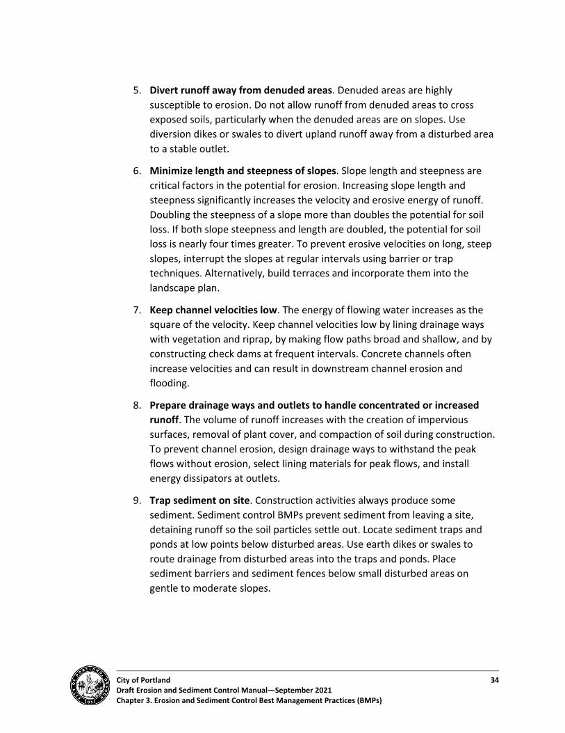
City of Portland 34 Draft Erosion and Sediment Control Manual—September 2021 Chapter 3. Erosion and Sediment Control Best Management Practices (BMPs)
5. Divert runoff away from denuded areas. Denuded areas are highly susceptible to erosion. Do not allow runoff from denuded areas to cross exposed soils, particularly when the denuded areas are on slopes. Use diversion dikes or swales to divert upland runoff away from a disturbed area to a stable outlet.
6. Minimize length and steepness of slopes. Slope length and steepness are critical factors in the potential for erosion. Increasing slope length and steepness significantly increases the velocity and erosive energy of runoff. Doubling the steepness of a slope more than doubles the potential for soil loss. If both slope steepness and length are doubled, the potential for soil loss is nearly four times greater. To prevent erosive velocities on long, steep slopes, interrupt the slopes at regular intervals using barrier or trap techniques. Alternatively, build terraces and incorporate them into the landscape plan.
7. Keep channel velocities low. The energy of flowing water increases as the square of the velocity. Keep channel velocities low by lining drainage ways with vegetation and riprap, by making flow paths broad and shallow, and by constructing check dams at frequent intervals. Concrete channels often increase velocities and can result in downstream channel erosion and flooding.
8. Prepare drainage ways and outlets to handle concentrated or increased runoff. The volume of runoff increases with the creation of impervious surfaces, removal of plant cover, and compaction of soil during construction. To prevent channel erosion, design drainage ways to withstand the peak flows without erosion, select lining materials for peak flows, and install energy dissipators at outlets.
9. Trap sediment on site. Construction activities always produce some sediment. Sediment control BMPs prevent sediment from leaving a site, detaining runoff so the soil particles settle out. Locate sediment traps and ponds at low points below disturbed areas. Use earth dikes or swales to route drainage from disturbed areas into the traps and ponds. Place sediment barriers and sediment fences below small disturbed areas on gentle to moderate slopes.

City of Portland 35 Draft Erosion and Sediment Control Manual—September 2021 Chapter 3. Erosion and Sediment Control Best Management Practices (BMPs)
10. Inspect and maintain control BMPs. Inspection and maintenance of control BMPs are vital. Most control BMPs require regular maintenance and problems can develop during a single storm. Inspect control BMPs frequently, particularly before, during, and after storm events, to ensure that they are working properly. Correct problems as soon as they develop. Assign responsibility for routine and time-sensitive inspections to one individual.
3.2. BMP Selection and Implementation Figure 3-1 outlines the process to select and implement BMPs in accordance with this Manual and maintain BMPs throughout the duration of construction.
• Step 1. Select and apply minimum BMPs to all projects regardless of size, location, and category. Step 1 also applies to projects that qualify as a Simple Site (see Section 2.1.3).
• Step 2. Select and apply additional or enhanced BMPs based on Special Site conditions (see Section 2.1.4). Note that Table 3-1 is not a comprehensive summary of activities or BMPs required for every project; select BMPs based on individual site conditions and project needs.
• Step 3. Ensure that BMPs do not conflict with tree protection fencing required for tree preservation by PCC Title 11, Trees, or Title 33, Planning and Zoning.
• Step 4. Apply targeted source controls based on the type of site use and type of pollutant generating activities (see Chapter 4).
• Step 5. Monitor, maintain, and adjust BMPs for the duration of ground disturbing activities in accordance with the performance standards outlined in Section 1.3.
• Step 6. Project Closeout, as described in Section 2.9.

City of Portland 36 Draft Erosion and Sediment Control Manual—September 2021 Chapter 3. Erosion and Sediment Control Best Management Practices (BMPs)
Figure 3-1. BMP selection flow chart
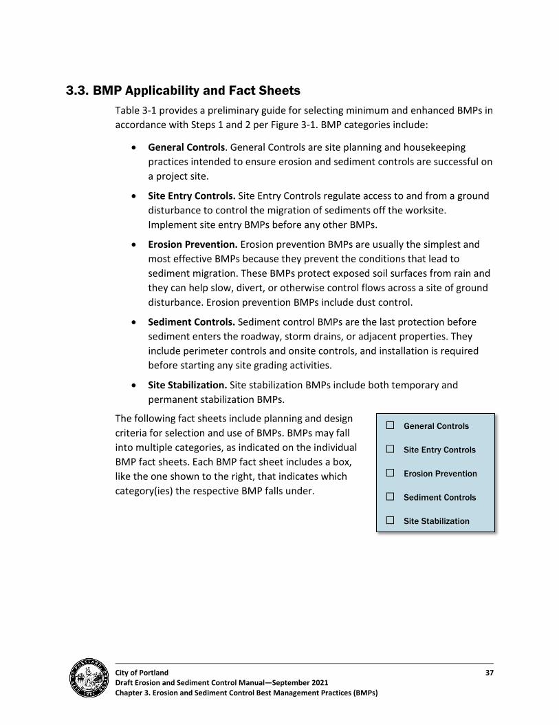
City of Portland 37 Draft Erosion and Sediment Control Manual—September 2021 Chapter 3. Erosion and Sediment Control Best Management Practices (BMPs)
3.3. BMP Applicability and Fact Sheets Table 3-1 provides a preliminary guide for selecting minimum and enhanced BMPs in accordance with Steps 1 and 2 per Figure 3-1. BMP categories include:
• General Controls. General Controls are site planning and housekeeping practices intended to ensure erosion and sediment controls are successful on a project site.
• Site Entry Controls. Site Entry Controls regulate access to and from a ground disturbance to control the migration of sediments off the worksite. Implement site entry BMPs before any other BMPs.
• Erosion Prevention. Erosion prevention BMPs are usually the simplest and most effective BMPs because they prevent the conditions that lead to sediment migration. These BMPs protect exposed soil surfaces from rain and they can help slow, divert, or otherwise control flows across a site of ground disturbance. Erosion prevention BMPs include dust control.
• Sediment Controls. Sediment control BMPs are the last protection before sediment enters the roadway, storm drains, or adjacent properties. They include perimeter controls and onsite controls, and installation is required before starting any site grading activities.
• Site Stabilization. Site stabilization BMPs include both temporary and permanent stabilization BMPs.
The following fact sheets include planning and design criteria for selection and use of BMPs. BMPs may fall into multiple categories, as indicated on the individual BMP fact sheets. Each BMP fact sheet includes a box, like the one shown to the right, that indicates which category(ies) the respective BMP falls under.
☐ General Controls
☐ Site Entry Controls
☐ Erosion Prevention
☐ Sediment Controls
☐ Site Stabilization

City of Portland 38 Erosion and Sediment Control Manual—September 2021 Chapter 3. Erosion and Sediment Control Best Management Practices (BMPs)
Table 3-1. BMP Applicability Guidelines (Minimum and Enhanced BMP Selection) Step 1. Apply MINIMUM BMPs to all ground disturbing projects.
Step 2. Apply ENHANCED BMPs based on Special Site conditions and characteristics. Additional BMPs (not reflected in this table) may be required based on individual project needs.
Ground Disturbance >10,000 SF
Projects in Environmental, River, or Greenway overlay zones, or within 50 ft. of a water
body or wetland
Slopes >10% Culverts/ In-Water
General Controls (Apply all)
• Reporting and Monitoring (Sect. 2.8) • Trash Debris Containment, Removal, and
Disposal (Sect. 4). • Erosion Control Signage (Sect. 2.4)
Project Scheduling and Sequencing (Sect. 2.3.4 and Sect. 2.3.5)
Turbidity Monitoring (Sect. 2.8.3)
Site Entry Controls
• BMP 3.12: Stabilized Construction Access BMP 3.13: Wheel Wash Structures and Equipment
Erosion Prevention (Apply as required)
• BMP 3.1: Preserve Natural Vegetation • BMP 3.4: Temporary Vegetative Cover • BMP 3.5: Mulch • BMP 3.6: Rolled Erosion Control Products • BMP 3.7: Plastic Sheeting • Other relevant BMPs • BMP 3.11. Dust Control
BMP 3.4: Temporary Vegetative Cover
BMP 3.18: Vegetative Buffers
• BMP 3.5: Mulch (with tackifier)
• BMP 3.6: Rolled Erosion Control Products
• BMP 3.10: Hydroseeding Fiber Rolls and Wattles
Sediment Controls (Apply as required)
• BMP 3.15: Temporary Sediment Control (Silt) Fence
• BMP 3.16: Filter Bags and Socks • BMP 3.17: Fiber Rolls and Wattles • BMP 3.19: Storm Drain Inlet Protection • Other relevant BMPs
BMP 3.29:
Turbidity Curtains
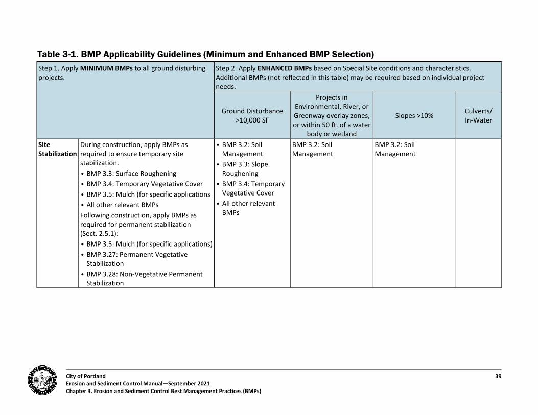
City of Portland 39 Erosion and Sediment Control Manual—September 2021 Chapter 3. Erosion and Sediment Control Best Management Practices (BMPs)
Table 3-1. BMP Applicability Guidelines (Minimum and Enhanced BMP Selection) Step 1. Apply MINIMUM BMPs to all ground disturbing projects.
Step 2. Apply ENHANCED BMPs based on Special Site conditions and characteristics. Additional BMPs (not reflected in this table) may be required based on individual project needs.
Ground Disturbance >10,000 SF
Projects in Environmental, River, or Greenway overlay zones, or within 50 ft. of a water
body or wetland
Slopes >10% Culverts/ In-Water
Site Stabilization
During construction, apply BMPs as required to ensure temporary site stabilization. • BMP 3.3: Surface Roughening • BMP 3.4: Temporary Vegetative Cover • BMP 3.5: Mulch (for specific applications • All other relevant BMPs Following construction, apply BMPs as required for permanent stabilization (Sect. 2.5.1): • BMP 3.5: Mulch (for specific applications) • BMP 3.27: Permanent Vegetative
Stabilization • BMP 3.28: Non-Vegetative Permanent
Stabilization
• BMP 3.2: Soil Management
• BMP 3.3: Slope Roughening
• BMP 3.4: Temporary Vegetative Cover
• All other relevant BMPs
BMP 3.2: Soil Management
BMP 3.2: Soil Management
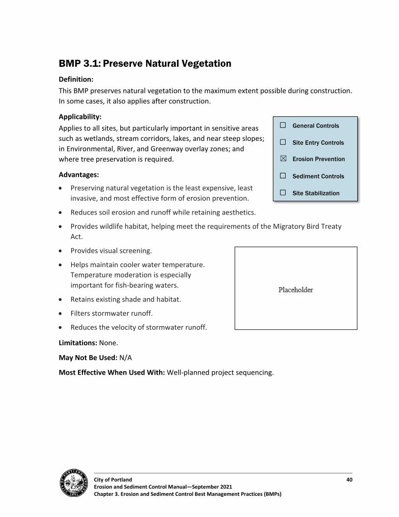
City of Portland 40 Erosion and Sediment Control Manual—September 2021 Chapter 3. Erosion and Sediment Control Best Management Practices (BMPs)
BMP 3.1: Preserve Natural Vegetation Definition: This BMP preserves natural vegetation to the maximum extent possible during construction. In some cases, it also applies after construction.
Applicability: Applies to all sites, but particularly important in sensitive areas such as wetlands, stream corridors, lakes, and near steep slopes; in Environmental, River, and Greenway overlay zones; and where tree preservation is required.
Advantages:
• Preserving natural vegetation is the least expensive, least invasive, and most effective form of erosion prevention.
• Reduces soil erosion and runoff while retaining aesthetics.
• Provides wildlife habitat, helping meet the requirements of the Migratory Bird Treaty Act.
• Provides visual screening.
• Helps maintain cooler water temperature. Temperature moderation is especially important for fish-bearing waters.
• Retains existing shade and habitat.
• Filters stormwater runoff.
• Reduces the velocity of stormwater runoff.
Limitations: None.
May Not Be Used: N/A
Most Effective When Used With: Well-planned project sequencing.
☐ General Controls
☐ Site Entry Controls
☒ Erosion Prevention
☐ Sediment Controls
☐ Site Stabilization

City of Portland 41 Erosion and Sediment Control Manual—September 2021 Chapter 3. Erosion and Sediment Control Best Management Practices (BMPs)
Purpose: To prevent erosion by preserving natural vegetation to the maximum extent possible.
• Planning Considerations - Review options for preserving natural vegetation during the pre-construction
conference (project manager, inspector, and contractor). - Establish a phased clearing and grading schedule at the start of the project. - Coordinate as needed with environmental professionals such as landscape architects
and arborists. - Fence or flag clearing limits and protection zones for trees and shrubs. - When removing trees and vegetation during the bird nesting season (February
through July), avoid harm to active/occupied bird nests protected by the federal Migratory Bird Treaty Act. Conduct a pre-survey using a qualified biologist.
• Design Specifications - Coordinate with the landscape architect and environmental professionals when
determining the goals and means for preserving vegetation. - Preserve vegetation in natural groups or as individual trees and shrubs. - Flag or mark ground disturbance limits outside the dripline of preserved trees. - Protect vegetation from:
o Injury by construction equipment. Injury to root systems is often less visible than above-ground damage and can result from scarring and cutting of roots.
o Compaction. Do not allow movement or parking of vehicles, or storage and stockpiling of materials within vegetation protection zones.
o Grade changes that affect plant root zones. Make smooth grade transitions, no closer than the tree’s dripline. Accommodate embankments around trees by placing a layer of ground drain rock or open graded aggregate and a tile system over roots before placing fill to allow air circulation. Do not place soil over root crowns or on trunks of trees. Consult an arborist when planning embankment around existing trees.
o Excavation. Terrace the area around plants or leave plants on an undisturbed mound to increase survival rates.
Maintenance Requirements:
• Inspect and repair flagging or fencing regularly.
• Re-cover exposed plant roots.
City of Portland 42 Erosion and Sediment Control Manual—September 2021 Chapter 3. Erosion and Sediment Control Best Management Practices (BMPs)
BMP 3.2: Soil Management Definition: Soil management practices protect and restore soil functions. They include retaining topsoil; roughening soil surfaces; amending, de-compacting, and terracing the soil; testing the soil; and other management practices that meet the same goals.
Applicability:
• All disturbed areas, including areas used for vehicle traffic and equipment and material storage.
• Exceptions include: - The building footprint. - Areas that are or will be made impervious as part of
the current project (e.g., driveways and sidewalks). - Areas where septic drain fields exist or will be
installed as part of the current project. This exception does not apply to reserve drain fields.
- Areas within the drip line of existing trees to be optionally retained. - Areas within the root protection zone of trees required to be preserved by Title 11
or Title 33. - Anywhere the original native soils have not been disturbed and/or displaced. - Any areas classified as critical slopes or with slopes of 33 percent or greater.
Advantages: Increased stormwater infiltration, healthier vegetation, less soil amendments, carbon sequestering, ecosystem reconnection.
Limitations: None.
May Not Be Used: N/A
Most Effective When Used With:
• Soil test results.
• Limited access to the site.
• Reserved areas for designated work, stockpiling, and staging.
• Stabilization of the final vegetation.
☐ General Controls
☐ Site Entry Controls
☐ Erosion Prevention
☐ Sediment Controls
☒ Site Stabilization

City of Portland 43 Erosion and Sediment Control Manual—September 2021 Chapter 3. Erosion and Sediment Control Best Management Practices (BMPs)
Purpose: To protect and restore soil functions, including a soil’s vulnerability to soil erosion (erodibility).
• Planning Considerations - Naturally occurring (undisturbed) soil and vegetation provide important stormwater
functions, including water infiltration; nutrient, sediment, and pollutant adsorption; sediment and pollutant biofiltration; water interflow storage and transmission; and pollutant degradation. These functions are largely lost when development strips away native soil and vegetation, replacing them with minimal topsoil and sod. The new landscape also generates pollutants with the increased use of pesticides, fertilizers and other landscaping and household/industrial chemicals, concentration of pet wastes, and pollutants from roadside litter.
- Establishing soil quality and depth regains greater stormwater functions in the post- development landscape, provides increased treatment of pollutants and sediments that result from development, and minimizes the need for some landscaping chemicals, thus reducing pollution through prevention.
- Evaluate locations for stockpiling and protecting topsoil, develop a plan that sequences construction and stabilization activities, and test the soil.
- Consider the cost savings to be gained from limiting the disturbance of native soils rather than amending soils.
• Design Specifications - Compacted surfaces must be roughened 6" to 12" immediately prior to topsoil
application. This will help ensure a good bond between the topsoil and subsoil. - Replaced topsoil must be a minimum of 8 inches thick and have an organic matter
content of 5 and 10 percent dry weight for turf areas and planting beds, respectively, based on results from a standard burn test. Replaced topsoil must also have a pH suitable for the proposed landscape plants.
- Prior to seeding, topsoil must be worked to prepare a proper seedbed. This includes raking of the topsoil and removal of debris and stones.
- During site preparation for permanent vegetative stabilization, soils must be removed or treated as necessary to permanently support adequate vegetative ground cover. If the removal or treatment of the soil will not provide suitable conditions, non-vegetative means of permanent ground stabilization must be employed–see BMP 3.28 for more information on non-vegetative permanent stabilization.
City of Portland 44 Erosion and Sediment Control Manual—September 2021 Chapter 3. Erosion and Sediment Control Best Management Practices (BMPs)
Maintenance Requirements:
• Establish soil quality and depth toward the end of construction and once established, protect from compaction, such as from large machinery use, and from erosion.
• Plant vegetation and mulch the amended soil area after installation.
• Leave plant debris or its equivalent on the soil surface to replenish organic matter.
• Reduce and adjust, where possible, the use of irrigation, fertilizers, herbicides and pesticides.
City of Portland 45 Erosion and Sediment Control Manual—September 2021 Chapter 3. Erosion and Sediment Control Best Management Practices (BMPs)
BMP 3.3: Surface Roughening Detail 3.3-A: Surface Roughening
Definition: Surface roughening includes a variety of methods for creating ridges, furrows, and terraces in the soil surface. These features run perpendicular to the slope and natural direction of runoff, slowing runoff and catching eroded soil, seeds and mulch.
Applicability:
• Bare soils where at least some erosion prevention BMPs are required.
• Slopes of more than 25 percent, with elevation changes greater than 5 vertical feet.
• Prior to seeding embankment slopes.
• Prior to installing a compost blanket.
• Prior to backfilling on subsoils.
• Prior to adding or amending topsoil. Roughen the top 12 inches of soil.
Advantages: Slows runoff and increases infiltration; trap seed for increased vegetation establishment; trap soil eroded from slopes above.
Limitations:
• On sites with slide or safety hazards, roughening may be used at the discretion of the responsible party.
• Tracking with a bulldozer or other heavy equipment may compact soil.
• Surface roughening must not be performed within tree protection fencing required by Title 11, Trees, Title 33, Planning & Zoning, or by land use review conditions of approval without a permit revision. In some cases, a report from a certified arborist may be required for permit revision approval.
May Not Be Used: N/A
☐ General Controls
☐ Site Entry Controls
☐ Erosion Prevention
☐ Sediment Controls
☒ Site Stabilization
City of Portland 46 Erosion and Sediment Control Manual—September 2021 Chapter 3. Erosion and Sediment Control Best Management Practices (BMPs)
Most Effective When Used With:
• Mulching
• Temporary/permanent vegetative cover
Purpose: To help establish vegetative cover, prevent erosion, allow for infiltration, and trap sediment by reducing runoff velocity.
• Planning Considerations - All vegetated sites require some surface roughening, such as stair stepping,
grooving, furrowing, or tracking. - The selection of an appropriate method depends on the type of slope and the
desired temporary or permanent slope vegetative treatment. - Develop grooves or furrows that lie perpendicular to (across) the slope. - Other planning considerations include slope steepness, mowing requirements, and
slope stability, including whether cutting or filling forms the slope.
• Design Specifications. The following design specifications are for disturbed areas where existing vegetation has been removed: - Track up and down the slope to leave track tread indentations perpendicular to
(across) the slope (see Detail 3.3-A). - Areas that will be mowed (slopes less than 33 percent) may have small furrows
parallel to the slope contours (across the slope) left by discing, harrowing, raking, or other grooving methods from seed planting machinery operated on the contour.
- Areas with vegetation that will not be mowed may be stair-step graded, grooved, or left rough after filling.
- Slopes steeper than 50 percent must be stair-stepped with benches. Stair-step grading is also appropriate for soils containing large amounts of rock. Each step catches material that sloughs from above and provides a level site to convey or detain drainage or establish vegetation. Stairs must be wide enough to work with standard earth-moving or maintenance equipment (12 feet minimum with no more than 15 percent slope). Heights must be slope specific but not exceed 3 feet without appropriate soils analysis or retaining structure support.
- Avoid excessive compaction of soils during roughening. - Seed and mulch roughened soil surfaces as quickly as possible. If conditions are not
appropriate for seeding, mulch or cover the area with an erosion control blanket.

City of Portland 47 Erosion and Sediment Control Manual—September 2021 Chapter 3. Erosion and Sediment Control Best Management Practices (BMPs)
• Installation Tips and Specifications - Cut furrows a minimum of 1 inch in depth. - Prevent concentrated flows to the slopes by diverting flows at the top of the slope
with diversion dikes or swales or slope drains. - Tracking with bulldozer treads is the minimal acceptable practice. Other roughening
forms (e.g., discing, benching, and terracing) are more effective. - Seed and groundcovers must be in place as soon as possible and must be fully
established before the beginning of the wet season. - Companion BMPs include mulching, vegetative cover, tackifier, plastic sheeting,
rolled erosion control blankets, and slope interrupters and attenuators.
Maintenance Requirements: Temporarily roughen areas lacking cover as soon as possible per the requirement in Section 1.3 of this Manual. Inspect the areas regularly, especially after storm events. If grooves or stair-steps fill with sediment, leaving less than one-third of the original groove or stair depth, remove the sediment and re-roughen if necessary.
Signs of Failure–Surface Roughening Symptoms Potential Cause Suggested Solution Bare soil in wet season
• Lack of adequate cover. • Mulch or appropriately cover to prevent rainfall contact.
Rill erosion • Lack of penetration of furrows.
• Migration of mulch. • Concentrated stormwater
flows.
• Regrade and recover. • Divert stormwater flows or install stormwater
velocity and quantity controls.
Migration of mulch
• Concentration of runoff from top of slope.
• Groundwater emergence. • Unstable soils.
• Provide adequate collection and conveyance system, e.g., a pipe slope drain.
• Install a trench drain to intercept drainage and groundwater seepage (discharge to approved disposal point).
• Provide tackifiers, properly punch in mulch cover, provide a rolled erosion control product that incorporates mulch into the net.
City of Portland 48 Erosion and Sediment Control Manual—September 2021 Chapter 3. Erosion and Sediment Control Best Management Practices (BMPs)
BMP 3.4: Temporary Vegetative Cover Definition: Temporary Vegetative Cover is typically grasses or grass/legume mixes planted to help control erosion during construction activities. Temporary vegetative cover is removed or replaced at the end of the project. Some grasses used for temporary cover can also be part of the permanent site vegetation. The Portland Plant List is a valuable reference for this BMP (see Planning Considerations).
Applicability:
• Ground surfaces likely to be exposed during the wet season (October 1 through April 30) or surfaces likely to be exposed for more than 3 weeks during the dry season.
• Areas not subjected to heavy wear and soil piles that are not used by ongoing construction traffic.
• Temporary stabilization of new or disturbed ditches, ponds, trenches, dikes, or swales.
Advantages:
• Eliminates splash erosion, traps sediment, promotes infiltration, reduces runoff velocities, and controls dust.
• Relatively inexpensive.
• Helps stabilize exposed soils without plastic or other artificial products and can aesthetically improve site.
• Helps provide root systems that bind soils during development.
• Helps provide organic matter for permanent soils.
Limitations:
• Needs sufficient time and cover for seed to establish.
• May require soil amendment, fertilizer, or lime to establish on poor soils.
• Must be removed prior to applying fill material.
May Not Be Used: On active stockpiles or by itself (without matting) after October 1.
Most Effective When Used With: Mulch, surface roughening, rolled erosion control products such as blankets, matting, netting, and other protective BMPs.
☐ General Controls
☐ Site Entry Controls
☒ Erosion Prevention
☐ Sediment Controls
☒ Site Stabilization
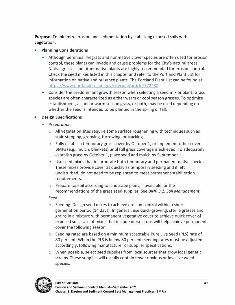
City of Portland 49 Erosion and Sediment Control Manual—September 2021 Chapter 3. Erosion and Sediment Control Best Management Practices (BMPs)
Purpose: To minimize erosion and sedimentation by stabilizing exposed soils with vegetation.
• Planning Considerations - Although perennial ryegrass and non-native clover species are often used for erosion
control, these plants can invade and cause problems for the City’s natural areas. Native grasses and other native plants are highly recommended for erosion control. Check the seed mixes listed in this chapter and refer to the Portland Plant List for information on native and nuisance plants. The Portland Plant List can be found at: https://www.portlandoregon.gov/citycode/article/322280
- Consider the predominant growth season when selecting a seed mix or plant. Grass species are often characterized as either warm or cool season grasses. To optimize establishment, a cool or warm season grass, or both, may be used depending on whether the seed is intended to be planted in the spring or fall.
• Design Specifications - Preparation
o All vegetation sites require some surface roughening with techniques such as stair-stepping, grooving, furrowing, or tracking.
o Fully establish temporary grass cover by October 1, or implement other cover BMPs (e.g., mulch, blankets) until full grass coverage is achieved. To adequately establish grass by October 1, place seed and mulch by September 1.
o Use seed mixes that incorporate both temporary and permanent native species. These mixes provide cover as quickly as temporary seeding and if left undisturbed, do not need to be replanted to meet permanent stabilization requirements.
o Prepare topsoil according to landscape plans, if available, or the recommendations of the grass seed supplier. See BMP 3.1: Soil Management.
- Seed o Seeding: Design seed mixes to achieve erosion control within a short
germination period (14 days). In general, use quick-growing, sterile grasses and grains in a mixture with permanent vegetative cover to achieve quick cover of exposed soils. Use of mixes that include nurse crops will help achieve permanent cover the following season.
o Seeding rates are based on a minimum acceptable Pure Live Seed (PLS) rate of 80 percent. When the PLS is below 80 percent, seeding rates must be adjusted accordingly, following manufacturer or supplier specifications.
o When possible, select seed supplies from local sources that grow local genetic strains. These supplies will usually contain fewer noxious or invasive weed species.
City of Portland 50 Erosion and Sediment Control Manual—September 2021 Chapter 3. Erosion and Sediment Control Best Management Practices (BMPs)
o Seed may be applied by three different methods: Broadcast: Seed is scattered on the soil surface by hand or machine. This
method is used mostly for smaller areas.
Hydroseeded: A mixture of water, seed, and sometimes fertilizers or mulch is sprayed onto exposed soils. This method is best for sites over 5,000 sq. ft. in size. (See BMP 3.10: Hydroseeding.)
Drilled: Seed is tamped down by equipment to inject seeds into exposed soils. This method is best for sites larger than 2 acres.
- Fertilization o Fertilize grass seed only as needed or as specified in the supplier’s
recommendations. Compost is a superior soil amendment. o If fertilizer is necessary, slow-release fertilizers are more efficient and have fewer
environmental impacts. o Use a non-phosphorus fertilizer for development areas within 50 feet of water
bodies and wetlands. o Nitrogen fertilizer is not recommended for grasses. o Spread composted or straw mulch uniformly, immediately following seeding.
- Mulch o Composted or straw mulch must be applied at double the hydroseed application
requirement (4,000 lbs./ac). o Composted or straw mulch must be anchored on steeper slopes (greater than
33 percent) by working it in by hand or with equipment (rollers, cleat tracks, etc.).
o Hydromulch must be applied with grass seed at a rate of 2,000 lbs./acre or as specified by the supplier.
o On slopes steeper than 10 percent, hydroseed and mulch must be applied with a bonding agent (tackifier). The application rate and methodology must be in accordance with seed supplier recommendations.
o Netting and anchors must be used as needed. For disturbed areas on slopes and in ditches/swales, erosion control blankets, biodegradable netting, or jute is desirable and may be used instead of bonding agents to provide a stable area for seeding. Netting must be installed as specified in BMP 3.6 and anchored in accordance with the manufacturer’s recommendations.
Materials: Table 3-2 identifies recommended temporary and permanent seeds and plants.
Table 3-3 lists nuisance grass species that must be avoided.

City of Portland 51 Erosion and Sediment Control Manual—September 2021 Chapter 3. Erosion and Sediment Control Best Management Practices (BMPs)
Table 3-2. Grasses and Other Groundcover Plants for Temporary or Permanent Vegetative Cover
Scientific Name Common Name Optimal Sowing Season
Germination Time (weeks) Co
mm
on (C
) or t
o Ad
d Di
vers
ity (D
)
Bios
wal
e or
Dry
Pon
d So
w R
ate
(Han
d, lb
s./a
cre)
Eros
ion
Cont
rol S
ow R
ate
(H
and,
lbs.
/acr
e)
Moisture Exposure Seed
Siz
e (S
, M, L
)
Commercial Accessibility of Local Eco-type
Taller Grasses–Wetter Areas Agrostis exarata Spike bentgrass Early fall/spring 1-4 D 5 30 Saturated to
wet Sun M Easy to medium,
Portland Metro Hordeum brachyantherum Meadow barley Early fall/spring 1-2 C 25 40 Wet to moist Sun L Easy to medium,
Willamette Valley Taller Grasses–Drier Areas Bromus sitchensis Sitka brome Early fall/spring 1-2 C 25 40 Wet to moist Sun/shade L Easy, Willamette Valley Bromus Carinatus (B. sitchensis var. carinatus)
California brome Early fall/spring 1-2 C 25 40 Dry to moist Sun L Easy, Portland Metro
Elymus glaucus Blue wildrye Early fall/spring 1-2 C 25 40 Dry to moist Sun to shade
L Easy, Portland Metro
Elymus trachycaulus Slender wheatgrass Early fall/spring 1-2 C 25 40 Dry to moist Sun L Medium to difficult, Willamette Valley
Shorter Grasses–Wetter Areas Deschampsia elongata Slender hairgrass Early fall/spring 1-3 C 20 30 Wet to dry Sun S Easy, Portland Metro

City of Portland 52 Erosion and Sediment Control Manual—September 2021 Chapter 3. Erosion and Sediment Control Best Management Practices (BMPs)
Table 3-2. Grasses and Other Groundcover Plants for Temporary or Permanent Vegetative Cover
Scientific Name Common Name Optimal Sowing Season
Germination Time (weeks) Co
mm
on (C
) or t
o Ad
d Di
vers
ity (D
)
Bios
wal
e or
Dry
Pon
d So
w R
ate
(Han
d, lb
s./a
cre)
Eros
ion
Cont
rol S
ow R
ate
(H
and,
lbs.
/acr
e)
Moisture Exposure Seed
Siz
e (S
, M, L
)
Commercial Accessibility of Local Eco-type
Recommended Non-Native Crop Cover Species Festuca rubra var. commutata Chewings fescue
Year round 1-3 C 20 30-40 Dry to moist Sun/shade S Medium to difficult,
Portland Metro
Triticum spp. Wheat
Year round 1-3 C 50 60 Dry to moist Sun L Easy, Willamette Valley
Avena spp. Oats Year round 1-3 C 50 60 Dry to moist L Easy, Willamette Valley
Regreen Sterile wheat hybrid
Year round 1-3 C 40 50 Dry to moist Sun L Medium to difficult, Portland Metro
Recommended Quick Establishment or Temporary Cover Crop Species Deschampsia elongata Slender hairgrass Early fall/spring 1-3 C 20 30 Wet to dry Sun S Easy, Portland Metro Festuca rubra var. commutata Chewings fescue Year round 1-3 C 20 30-40 Dry to moist Sun/shade S Medium to difficult,
Portland Metro Hordeum brachyantherum Meadow barley Early fall/spring 1-2 C 25 40 Wet to moist Sun L Easy to medium,
Willamette Valley Bromus sitchensis Sitka brome Early fall/spring 1-2 C 25 40 Wet to moist Sun/shade L Easy, Willamette
Valley Bromus carinatum California brome Early fall/spring 1-2 C 25 40 Dry to moist Sun L Easy, Portland Metro

City of Portland 53 Erosion and Sediment Control Manual—September 2021 Chapter 3. Erosion and Sediment Control Best Management Practices (BMPs)
Table 3-2. Grasses and Other Groundcover Plants for Temporary or Permanent Vegetative Cover
Scientific Name Common Name Optimal Sowing Season
Germination Time (weeks) Co
mm
on (C
) or t
o Ad
d Di
vers
ity (D
)
Bios
wal
e or
Dry
Pon
d So
w R
ate
(Han
d, lb
s./a
cre)
Eros
ion
Cont
rol S
ow R
ate
(H
and,
lbs.
/acr
e)
Moisture Exposure Seed
Siz
e (S
, M, L
)
Commercial Accessibility of Local Eco-type
Elymus glaucus Blue wildrye Early fall/spring 1-2 C 25 40 Dry to moist Sun to shade
L Easy, Portland Metro
Elymus trachycaulus Slender wheatgrass Early fall/spring 1-2 C 25 40 Dry to moist Sun L Medium to difficult, Willamette Valley
Forbs Gilia capitata Blue gilia Fall/spring D 2 1 (w/grass) Dry to moist Sun M Medium, Willamette
Valley Lotus purshianus Spanish clover Fall D 2 1 (w/grass) Dry to moist Sun M Medium, Willamette
Valley Lupinus albicaulis Sickle keel lupine Fall D 1 1 (w/grass) Dry to moist Sun L Medium, Willamette
Valley Lupinus rivularis Stream lupine Fall D 1 1 (w/grass) Dry to moist Sun L Medium, Willamette
Valley

City of Portland 54 Erosion and Sediment Control Manual—September 2021 Chapter 3. Erosion and Sediment Control Best Management Practices (BMPs)
Table 3-3. Nuisance Grass Species Not Recommended for Use on Erosion Control or Stormwater Projects or Not Allowed for Use in Environmental Zones
Species Common Name State-Listed Noxious Weed?
Portland Nuisance Plant?
Agropyron repens Quackgrass Yes (B-list) Yes Agrostis alba Redtop Bentgrass No Yes Agrostis tenuis/capillaris Colonial Bentgrass No Yes Alopecuris pratensis Meadow foxtail No Yes Anthoxanthum odoratum Sweet vernal grass No Yes Arrhenatherum elatius Tall oatgrass No Yes Brachypodium sylvaticum1 False brome Yes (B-list) Yes Bromus diandrus Ripgut No Yes Bromus hordaceus Smooth brome No Yes Bromus inermis Smooth brome No Yes Bromus japonicus Japanese brome No Yes Bromus sterilis Poverty grass No Yes Bromus tectorum Cheatgrass No Yes Festuca arundinacea Tall fescue No Yes Holcus lanatus Velvet grass No Yes Lolium multiflorum Annual ryegrass No Yes Phalaria arundinacea Reed canary grass No Yes Phalaris aquatica Harding grass No Yes Phleum pratense Timothy No Yes Phragmites australis1 Common reed No Yes Vulpia myoros Rat-tailed fescue No Yes
1. Prohibited in the City in any setting per Portland City Code Title 29.
Erosion Control Seed Mixes and Sources: The City of Portland recommends native seed mixes and plants for erosion control, for both temporary and permanent BMPs. Additionally, the use of native species found on the Portland Plant List is required in all Environmental Zones, per City of Portland Zoning Code (Title 33). Perennial ryegrass and non-native clovers are often used for erosion control, but they are invasive and can create problems beyond your site. The City discourages their use.
City of Portland 55 Erosion and Sediment Control Manual—September 2021 Chapter 3. Erosion and Sediment Control Best Management Practices (BMPs)
Maintenance Requirements:
• Watering: Seeding must be supplied with adequate moisture to establish grass. Water must be supplied as needed, especially in hot or dry weather or on geographically challenging and special sites. Water application rates must be controlled to provide adequate moisture without causing runoff.
• Reseeding: Areas that fail to establish grass cover must be reseeded as soon as such areas are identified, and all appropriate BMPs must be implemented to establish adequate cover.
• Weed Control: The type of weed control (mechanical, hand removal, biological, or chemical methods) must be specified. Chemical use is a last resort. Chemicals must never be used within stormwater management facilities. The selected weed control regime must adequately protect the selected seed mix.
Removal Specifications:
• At the end of site development, remove site erosion prevention and sediment control BMPs only after an approved permanent site landscaping or healthy stand of grass (or alternative vegetation as approved) is established. Perimeter sediment control BMPs must be the last BMPs removed after stabilization is established.
• To remove, till the grasses into the ground if they are in permanent landscape areas or choose sterile seeds that will not return after one growing season. Grasses may need to be removed completely under hardscape areas.
Signs of Failure–Temporary Vegetative Cover Symptoms Potential Cause Suggested Solution Dying grass • Lack of adequate water.
• Lack of soil nutrients. • Lack of air pores in soil (soil too
compacted).
• Provide temporary irrigation. • Top-dress with compost to hold
moisture and provide nutrients and heat for seeds.
Bare spots in vegetative cover
• Lack of seed contact with ground. • Seeding rate too low.
• Rake, drill, or walk in seed to ensure good ground contact.
• Overseed bare areas and ensure adequate water and nutrients.
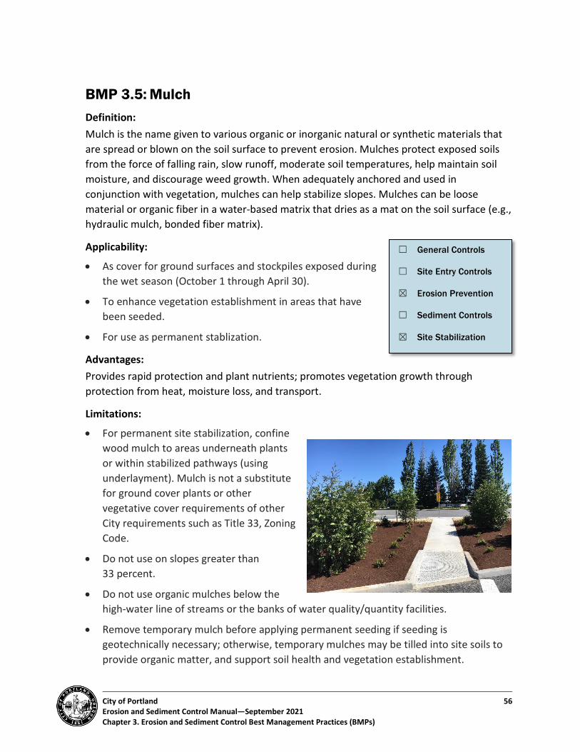
City of Portland 56 Erosion and Sediment Control Manual—September 2021 Chapter 3. Erosion and Sediment Control Best Management Practices (BMPs)
BMP 3.5: Mulch Definition: Mulch is the name given to various organic or inorganic natural or synthetic materials that are spread or blown on the soil surface to prevent erosion. Mulches protect exposed soils from the force of falling rain, slow runoff, moderate soil temperatures, help maintain soil moisture, and discourage weed growth. When adequately anchored and used in conjunction with vegetation, mulches can help stabilize slopes. Mulches can be loose material or organic fiber in a water-based matrix that dries as a mat on the soil surface (e.g., hydraulic mulch, bonded fiber matrix).
Applicability:
• As cover for ground surfaces and stockpiles exposed during the wet season (October 1 through April 30).
• To enhance vegetation establishment in areas that have been seeded.
• For use as permanent stablization.
Advantages: Provides rapid protection and plant nutrients; promotes vegetation growth through protection from heat, moisture loss, and transport.
Limitations:
• For permanent site stabilization, confine wood mulch to areas underneath plants or within stabilized pathways (using underlayment). Mulch is not a substitute for ground cover plants or other vegetative cover requirements of other City requirements such as Title 33, Zoning Code.
• Do not use on slopes greater than 33 percent.
• Do not use organic mulches below the high-water line of streams or the banks of water quality/quantity facilities.
• Remove temporary mulch before applying permanent seeding if seeding is geotechnically necessary; otherwise, temporary mulches may be tilled into site soils to provide organic matter, and support soil health and vegetation establishment.
☐ General Controls
☐ Site Entry Controls
☒ Erosion Prevention
☐ Sediment Controls
☒ Site Stabilization

City of Portland 57 Erosion and Sediment Control Manual—September 2021 Chapter 3. Erosion and Sediment Control Best Management Practices (BMPs)
May Not Be Used:
Application of hog fuel and shredded construction waste products is prohibited.
Most Effective When Used With: Seeding.
Purpose: Mulch minimizes erosion by providing a protective cover over disturbed, bare, or reseeded soils and will help ensure the success of seeding or revegetation. Minimal thickness protects soils from splash erosion, while thicker layers are effective for additional sediment control.
• Planning Considerations - Materials must be loose and free of significant sediment loads. - Mulches must be spread uniformly throughout the entire area and may be
integrated into the top layer of soil if appropriate. - Netting over mulch may be effective while vegetative cover is established - Mulches are most effective when anchored, especially organic mulches. Anchoring
can include punching materials into the soil, mixing mulches with tackifier products, or combining mulches with erosion blankets or netting. Mulch may otherwise migrate offsite. Because of this potential for movement, mulched areas require regular inspection and maintenance and may need replenishment over time.
- On slopes or any location where mulch is susceptible to movement by wind or water, mulch must be fixed in place with hydraulically applied tackifier or anchored mechanically.
• Design Specifications - Apply mulches at the rates specified in Table 3-4. - Do not use mulch made from nuisance plants listed in the Portland Plant List or
weeds.
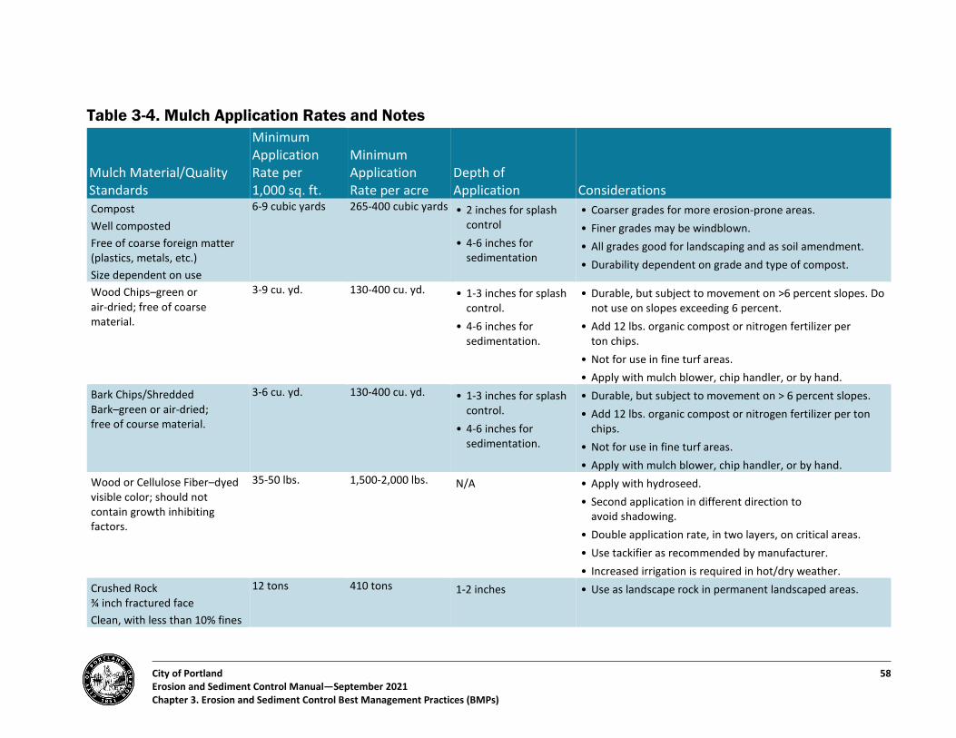
City of Portland 58 Erosion and Sediment Control Manual—September 2021 Chapter 3. Erosion and Sediment Control Best Management Practices (BMPs)
Table 3-4. Mulch Application Rates and Notes
Mulch Material/Quality Standards
Minimum Application Rate per 1,000 sq. ft.
Minimum Application Rate per acre
Depth of Application Considerations
Compost Well composted Free of coarse foreign matter (plastics, metals, etc.) Size dependent on use
6-9 cubic yards 265-400 cubic yards • 2 inches for splash control
• 4-6 inches for sedimentation
• Coarser grades for more erosion-prone areas. • Finer grades may be windblown. • All grades good for landscaping and as soil amendment. • Durability dependent on grade and type of compost.
Wood Chips–green or air-dried; free of coarse material.
3-9 cu. yd. 130-400 cu. yd. • 1-3 inches for splash control.
• 4-6 inches for sedimentation.
• Durable, but subject to movement on >6 percent slopes. Do not use on slopes exceeding 6 percent.
• Add 12 lbs. organic compost or nitrogen fertilizer per ton chips.
• Not for use in fine turf areas. • Apply with mulch blower, chip handler, or by hand.
Bark Chips/Shredded Bark–green or air-dried; free of course material.
3-6 cu. yd. 130-400 cu. yd. • 1-3 inches for splash control.
• 4-6 inches for sedimentation.
• Durable, but subject to movement on > 6 percent slopes. • Add 12 lbs. organic compost or nitrogen fertilizer per ton
chips. • Not for use in fine turf areas. • Apply with mulch blower, chip handler, or by hand.
Wood or Cellulose Fiber–dyed visible color; should not contain growth inhibiting factors.
35-50 lbs. 1,500-2,000 lbs. N/A • Apply with hydroseed. • Second application in different direction to
avoid shadowing. • Double application rate, in two layers, on critical areas. • Use tackifier as recommended by manufacturer. • Increased irrigation is required in hot/dry weather.
Crushed Rock ¾ inch fractured face Clean, with less than 10% fines
12 tons 410 tons 1-2 inches • Use as landscape rock in permanent landscaped areas.
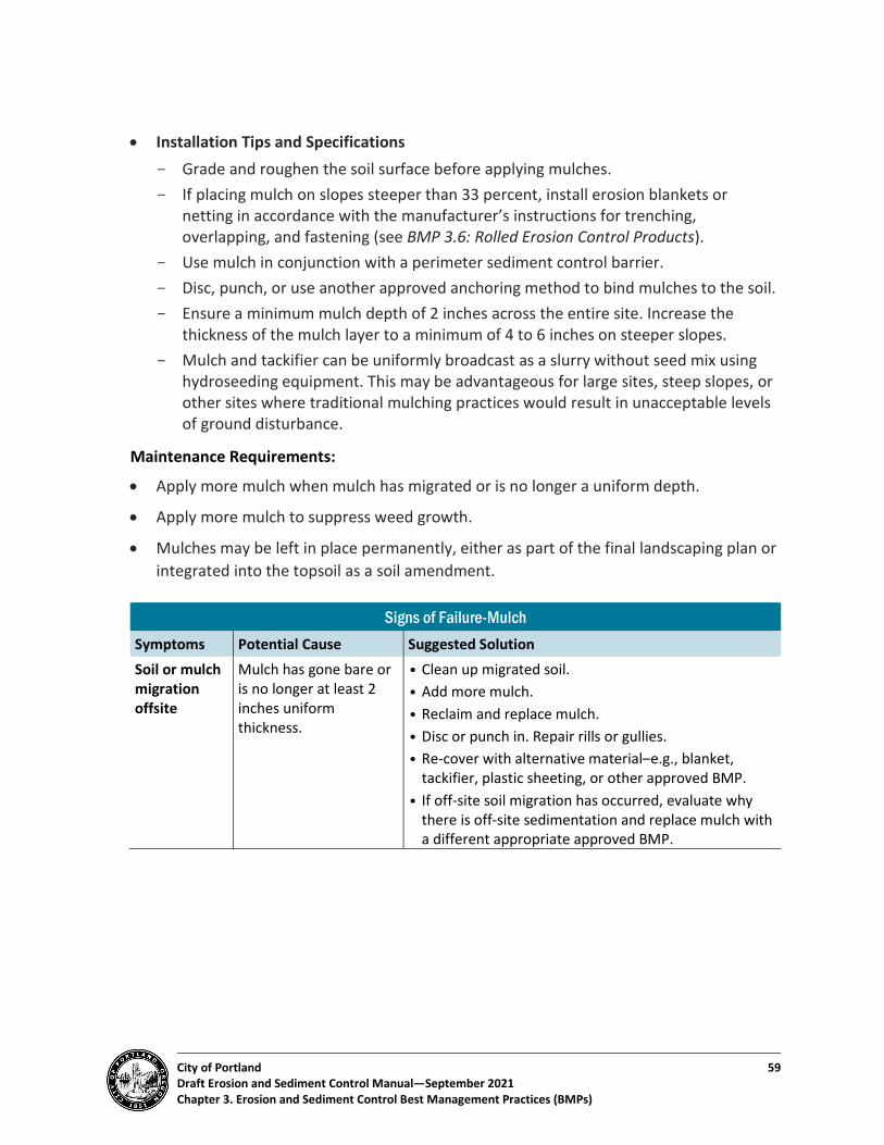
City of Portland 59 Draft Erosion and Sediment Control Manual—September 2021 Chapter 3. Erosion and Sediment Control Best Management Practices (BMPs)
• Installation Tips and Specifications - Grade and roughen the soil surface before applying mulches. - If placing mulch on slopes steeper than 33 percent, install erosion blankets or
netting in accordance with the manufacturer’s instructions for trenching, overlapping, and fastening (see BMP 3.6: Rolled Erosion Control Products).
- Use mulch in conjunction with a perimeter sediment control barrier. - Disc, punch, or use another approved anchoring method to bind mulches to the soil. - Ensure a minimum mulch depth of 2 inches across the entire site. Increase the
thickness of the mulch layer to a minimum of 4 to 6 inches on steeper slopes. - Mulch and tackifier can be uniformly broadcast as a slurry without seed mix using
hydroseeding equipment. This may be advantageous for large sites, steep slopes, or other sites where traditional mulching practices would result in unacceptable levels of ground disturbance.
Maintenance Requirements:
• Apply more mulch when mulch has migrated or is no longer a uniform depth.
• Apply more mulch to suppress weed growth.
• Mulches may be left in place permanently, either as part of the final landscaping plan or integrated into the topsoil as a soil amendment.
Signs of Failure-Mulch Symptoms Potential Cause Suggested Solution Soil or mulch migration offsite
Mulch has gone bare or is no longer at least 2 inches uniform thickness.
• Clean up migrated soil. • Add more mulch. • Reclaim and replace mulch. • Disc or punch in. Repair rills or gullies. • Re-cover with alternative material–e.g., blanket,
tackifier, plastic sheeting, or other approved BMP. • If off-site soil migration has occurred, evaluate why
there is off-site sedimentation and replace mulch with a different appropriate approved BMP.
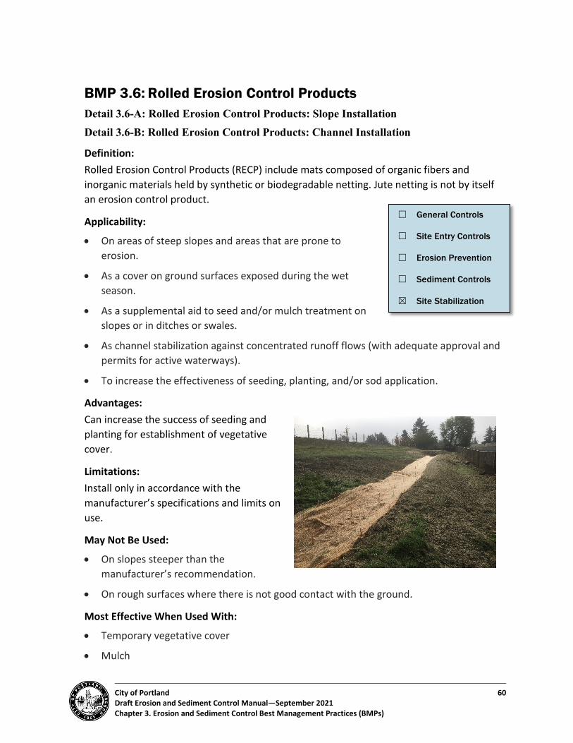
City of Portland 60 Draft Erosion and Sediment Control Manual—September 2021 Chapter 3. Erosion and Sediment Control Best Management Practices (BMPs)
BMP 3.6: Rolled Erosion Control Products Detail 3.6-A: Rolled Erosion Control Products: Slope Installation Detail 3.6-B: Rolled Erosion Control Products: Channel Installation
Definition: Rolled Erosion Control Products (RECP) include mats composed of organic fibers and inorganic materials held by synthetic or biodegradable netting. Jute netting is not by itself an erosion control product.
Applicability:
• On areas of steep slopes and areas that are prone to erosion.
• As a cover on ground surfaces exposed during the wet season.
• As a supplemental aid to seed and/or mulch treatment on slopes or in ditches or swales.
• As channel stabilization against concentrated runoff flows (with adequate approval and permits for active waterways).
• To increase the effectiveness of seeding, planting, and/or sod application.
Advantages: Can increase the success of seeding and planting for establishment of vegetative cover.
Limitations: Install only in accordance with the manufacturer’s specifications and limits on use.
May Not Be Used:
• On slopes steeper than the manufacturer’s recommendation.
• On rough surfaces where there is not good contact with the ground.
Most Effective When Used With:
• Temporary vegetative cover
• Mulch
☐ General Controls
☐ Site Entry Controls
☐ Erosion Prevention
☐ Sediment Controls
☒ Site Stabilization

City of Portland 61 Draft Erosion and Sediment Control Manual—September 2021 Chapter 3. Erosion and Sediment Control Best Management Practices (BMPs)
Purpose: To provide immediate protection and physical stabilization of disturbed soils. . Blankets are usually left in place as a permanent BMP.
• Planning Considerations - For detailed information on RECP types, visit the Erosion Control Technology Council
fact sheet at: https://www.ectc.org/rolled-erosion-control-products-recps-. - Consider installing fiber rolls/wattles or other barriers on top of erosion control
products at various locations on the slope to reduce the length of slope that receives high-speed flows. Use of rolls at the toe of the slope on streambanks will help secure the blanket and protect it from active wave/current action.
- If inspection is required, obtain inspection before covering the blanket with mulch or installing plantings through the blanket.
- Deformed plastic filament matting may be used for stream velocity protection and other special applications when approved by the applicable jurisdiction.
- Provide additional seed over and under mat installations to enhance vegetative cover growth.
- Blankets must be loose enough to allow good contact with the ground. - Blankets are often left in place as permanent features. If they are temporary:
o Stakes or staples must be biodegradable. o During removal, roll blankets from the bottom of the slope or the downstream
end of a channel to the top to trap sediment in the blanket roll. o Consider reusing any blankets removed from channels and in good condition as
cover for banks or other sloped areas. - Choose the appropriate RECP based on desired sheer strength, possible exposure to
UV and other elements, and length of time that coverage is needed. Straw, wood/excelsior, coconut, and synthetic are typical fiber types, and have varying degradation times, costs, coverage types, and installation requirements.
- The Erosion Control Technology Council makes the recommendations for erosion control blanket use (see Table 3-5).

City of Portland 62 Draft Erosion and Sediment Control Manual—September 2021 Chapter 3. Erosion and Sediment Control Best Management Practices (BMPs)
Table 3-5. Recommended Spacing for Live Fascines1
(measured along the bank face)
Slope Steepness Undisturbed Erosive Soils
Undisturbed Cohesive Soils Fill Soils2
33% or flatter 3-5 feet 5-7 feet 3-5 feet Steeper than 33%, up to 100% 3 feet 3-5 feet 0
1. Source: Robbin B. Sotir & Associates, Inc. 2. Not recommended alone; use with erosion blankets.
• Design Specifications - See standard detail drawings 3.6-A and 3.6-B for detail drawings. - Install blankets in firm contact with the soil, without voids beneath the blankets, to
prevent erosion beneath them. Erosion blankets must be securely trenched in at the top of the slope and anchored to the slope in accordance with the manufacturer’s recommendations (usually 1 anchor per 12 inches).
• Installation Tips and Specifications - Allow adequate material for overlaps and trenching. - Organic and/or thicker materials will provide enhanced protection of soils. - Extra staples or anchoring must be used on steep slopes in accordance with the
manufacturer’s recommendations. - Groundcover and other plants can be planted through the blanket to provide
permanent erosion protection. - Consider using bioengineered systems in areas that need permanent vegetative
cover or are in environmentally sensitive areas.
Maintenance Requirements:
• Inspect products daily for deformation or areas of sloughing under the surface.
• If plant growth is not establishing as desired, consider spreading additional seed on top of the blanket.

City of Portland 63 Draft Erosion and Sediment Control Manual—September 2021 Chapter 3. Erosion and Sediment Control Best Management Practices (BMPs)
Signs of Failure–Rolled Erosion Control Products Symptoms Potential Cause Suggested Solution Blanket moved or deformed
• Improperly or inadequately staked.
• Joints not properly overlapped or secure.
• Concentrated flows are directed into joint or weakly staked areas.
• After adequately repairing erosional damage under blanket:
• Adjust and re-anchor blanket. • Control or reduce upstream flows.
Slope creep/undermining
• Blanket not making good contact with soils.
• Flows directed under blanket edge.
• Groundwater or slope failure issue.
• After adequately repairing erosional damage under blanket:
• Add additional stakes to have blanket conform to contours of soils.
• Ensure edges are anchored under incoming flows (in trench, under outfall, etc.).
• Have qualified design professional check slope stability.
Erosion occurred • Flows too high for type of blanket used.
• Blanket not secured.
• After adequately repairing erosional damage under blanket:
• Choose blanket rated to withstand site flows.
• Re-anchor blanket.
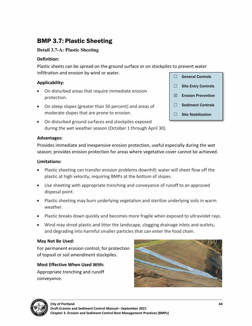
City of Portland 64 Draft Erosion and Sediment Control Manual—September 2021 Chapter 3. Erosion and Sediment Control Best Management Practices (BMPs)
BMP 3.7: Plastic Sheeting Detail 3.7-A: Plastic Sheeting
Definition: Plastic sheets can be spread on the ground surface or on stockpiles to prevent water infiltration and erosion by wind or water.
Applicability:
• On disturbed areas that require immediate erosion protection.
• On steep slopes (greater than 50 percent) and areas of moderate slopes that are prone to erosion.
• On disturbed ground surfaces and stockpiles exposed during the wet weather season (October 1 through April 30).
Advantages: Provides immediate and inexpensive erosion protection, useful especially during the wet season; provides erosion protection for areas where vegetative cover cannot be achieved.
Limitations:
• Plastic sheeting can transfer erosion problems downhill; water will sheet flow off the plastic at high velocity, requiring BMPs at the bottom of slopes.
• Use sheeting with appropriate trenching and conveyance of runoff to an approved disposal point.
• Plastic sheeting may burn underlying vegetation and sterilize underlying soils in warm weather.
• Plastic breaks down quickly and becomes more fragile when exposed to ultraviolet rays.
• Wind may shred plastic and litter the landscape, clogging drainage inlets and outlets, and degrading into harmful smaller particles that can enter the food chain.
May Not Be Used: For permanent erosion control; for protection of topsoil or soil amendment stockpiles.
Most Effective When Used With: Appropriate trenching and runoff conveyance.
☐ General Controls
☐ Site Entry Controls
☒ Erosion Prevention
☐ Sediment Controls
☐ Site Stabilization

City of Portland 65 Draft Erosion and Sediment Control Manual—September 2021 Chapter 3. Erosion and Sediment Control Best Management Practices (BMPs)
Purpose: To provide immediate and temporary erosion protection, usually for small areas, where vegetative cover cannot be achieved because of soil conditions, steep slopes, or time of year. Plastic sheets can provide temporary erosion protection on soils, spoils, and other erodible stockpiles. Plastic sheets can also be used to direct runoff water to an approved disposal point.
• Planning Considerations - Plastic sheeting is not the preferred choice for erosion prevention cover, except for
protection of a stockpile that must be kept dry for reuse. - Erosion control blankets, mulch, or seeding are preferred for soil stabilization and
erosion control.
• Design Specifications - Plastic sheeting must be polyethylene (any color is acceptable) with a minimum
thickness of 6 mil. - Sheeting must be maintained tightly in place by using staples, stakes, sandbags, 12–
inch-diameter rock, cinder blocks, or other rough surface materials with substantial weight.
- Sheeting must be applied as a continuous sheet whenever possible. All seams must be taped, appropriately welded, or weighted down for the full length of the seam with at least a 12-inch overlap of all seams. For seams parallel to the slope contour, the uphill sheet must overlap the downhill sheet. For seams crossing up and down slope, the sheeting must be laid so the top sheet faces away from any prevailing wind.
- No runoff can run under the plastic covering. - Collection trenches must be placed at the top and around the base of any slope or
stockpile or other area using sheeting. The top trench must direct concentrated flows away from the sheeting to an appropriate collection and conveyance system (e.g., pipe slope drains or swales). The trench may be designed and used to assist in conveyance as well as anchoring. The bottom trench must be sized and stabilized to adequately route and control flows from the sheeting surface.
- Drainage from plastic sheeting must be controlled to prevent discharge of runoff directly onto uncontrolled, undisturbed areas of the development site.
• Installation Tips and Specifications - Apply in a continuous sheet covering the slope or pile where possible. - Secure edges tightly. Check seams and material condition often. Inspect weights
frequently to ensure the plastic stays in place. - Maintain and adequately size drainage trenches to carry flows generated by the
plastic.

City of Portland 66 Draft Erosion and Sediment Control Manual—September 2021 Chapter 3. Erosion and Sediment Control Best Management Practices (BMPs)
- Topsoil under plastic may become anaerobic, killing various organisms that make soil healthy. Because it is uncertain how long it takes for anaerobic conditions to develop, consider using grass cover instead to hold topsoil and improve topsoil health.
Maintenance Requirements
• Visually inspect plastic sheeting daily for tears or weak points, and after every storm.
• Check areas receiving runoff from plastic sheeting daily for erosion.
• All plastic sheeting must be removed at the end of the project.
Signs of Failure–Plastic Sheeting Symptoms Potential Cause Suggested Solution Seams split/fabric torn
• Too much weight strain. • Inadequate overlap or weld. • Wind shear.
• Adjust plastic layers and anchoring, choosing more and lighter anchoring materials.
• Weld seams appropriately. • Cover with duct tape or additional plastic.
Fabric blown off/bare soils
• Wind shear. • Replace plastic and add extra anchoring.

City of Portland 67 Draft Erosion and Sediment Control Manual—September 2021 Chapter 3. Erosion and Sediment Control Best Management Practices (BMPs)
BMP 3.8: Armoring Detail 3.8-A: Armoring Detail 3.8-B: Gabions
Definition: Armoring refers to a variety of erosion prevention BMPs that will withstand high stormwater flow and discharge rates. Armoring reduces the speed of concentrated flow, dissipating energy to prevent scour at conveyance outlets and lowering the potential for downstream erosion. These BMPs are often permanent, and include riprap, gabions, reinforced soil retaining systems, cellular confinement systems, articulated mats, and plates.
Applicability:
• At the outlets of ponds, pipe slope drains, ditches, or other conveyances where high flows are anticipated.
• For high-flow channel stabilization.
Advantages:
• Permanence (if desired) and ease of installation.
• Many armoring systems can be installed with a large vegetative component that will provide additional environmental and erosion control benefits.
Limitations:
• Use of armoring systems in waterways may be prohibited and will likely require a variety of permits from state and federal natural resource protection agencies.
• Bioengineering techniques are the preferred alternative in bank and waterway projects because of their ability to provide upland habitat for animals and instream habitat for salmonids.
May Not Be Used: N/A
Most Effective When Used With:
• Upstream erosion control BMPs to reduce sediment deposition in the armoring installation.
• Upstream stormwater velocity and quantity controls.
☐ General Controls
☐ Site Entry Controls
☒ Erosion Prevention
☐ Sediment Controls
☐ Site Stabilization

City of Portland 68 Draft Erosion and Sediment Control Manual—September 2021 Chapter 3. Erosion and Sediment Control Best Management Practices (BMPs)
• Geotextile underlayment or high sheer strength rolled erosion control products.
Purpose: To provide erosion protection and stabilization for slopes, discharge points such as outfalls, and streambanks (occasionally). They are best used under high flow or unstable soil conditions.
• Planning Considerations - BMP 3.9-Soil Bioengineering is preferred for permanent installations. When possible,
use bioengineering, sod installation, or rolled erosion control products rated to withstand design flows. Structures or hardscape materials must be used only when other options are insufficient.
- While reinforced soil retaining systems–preformed structural systems that are laid atop soils and then backfilled with a variety of materials–can be more expensive than other installations, the ease of installation and permanency can make them desirable. These systems may require separate permit for plan review and inspection.
• Design Specifications - All materials must be installed per the manufacturer’s guidance and must be
designed by a licensed professional when required by the permitting authority. - A licensed professional must be consulted if the site presents high flow, steep slope,
or poor soil conditions. - Follow the general installation principles below unless the manufacturer’s
instructions specify a different installation method: o Excavate the application area to a depth that ensures that systems have
adequate foundations and are keyed in well. Most reinforced soil retaining systems need to be set so they are flush with, or slightly lower than, adjacent terrain. The exposed surface must be leveled and free of minor obstructions such as stones and debris. Major obstructions can be left in place, with materials established around them. Soils must be compacted or removed as necessary.
o Lay panels or sheets on the exposed surface. Use appropriate pins, hinges, staples, hog rings, or overlapping suggested by the manufacturer. Trench in the top, bottom, or sides of the panel or sheets as specified by the manufacturer.
o Anchor reinforced soil-retaining systems per the manufacturer’s instructions. Anchoring must occur at least along slope crests, upstream system edges, steep areas, and areas likely to experience the highest turbulence from nearby surface water systems.
o Fill systems with material of choice, as rated for the selected system. Consider using some element of vegetative cover to enhance aesthetics and provide habitat.

City of Portland 69 Draft Erosion and Sediment Control Manual—September 2021 Chapter 3. Erosion and Sediment Control Best Management Practices (BMPs)
• Installation Tips and Specifications - Make sure there is a good foundation with adequately compacted soils. - Adequately anchor the installation, especially on slope crests, upstream edges, and
other areas with steep slopes or high velocity flows. - Consider overseeding or otherwise planting systems to enhance appearance and
performance.
Maintenance Requirements:
• All systems must be maintained as installed for the life of the BMP. System repair typically consists of additional anchoring or top-dressing with fill materials on an as-needed basis.
• Reinforced soil retaining systems are almost always used as permanent site features. Some systems may be used for temporary roadways. If the system is temporary, loosen underlying soils after removal to allow for infiltration. Seed and mulch if the area is to remain pervious.
Signs of Failure-Armoring Symptoms Potential Cause Suggested Solution System is broken or otherwise compromised
• Flow is too intense. • Materials are weak. • Improper installation.
• Revisit flow calculations. • Add additional material supports or fill
support materials. • Overseed or overplant with vegetation to
help hold in fill material. System has slid or been displaced
• Foundation was insufficiently compacted, and the slope slipped.
• System was not adequately anchored.
• Reestablish slope; compact and reinstall system.
• Replace and add additional anchors to system.
Erosion has occurred
• Flows are too high for type of system used.
• Flows are undermining the system. • Fill materials are missing.
• After adequately repairing erosional damage under or within system:
• Choose system rated to withstand site flows.
• Replace and/or re-anchor system. • Add additional fill as necessary. • Overseed or otherwise vegetate system to
hold fill material.
City of Portland 70 Draft Erosion and Sediment Control Manual—September 2021 Chapter 3. Erosion and Sediment Control Best Management Practices (BMPs)
BMP 3.9: Biotechnical and Soil Bioengineering Detail 3.9-A: Bioengineered Soils: Live Stakes Detail 3.9-B: Bioengineered Soils: Live Fascines Detail 3.9-C: Bioengineered Soils: Live Fascine Slope Installation
Definition: Biotechnical and soil bioengineering stabilization practices are engineered systems that protect slopes against surface erosion and shallow mass movement using natural and living systems.
Applicability:
• Streambank restoration or construction projects.
• Simple, shallow slope stabilization projects.
• Slopes where permanent vegetation, but no mowing, is desired.
• Retaining walls, live crib walls, gabions, revetments, and other stabilization BMPs.
Advantages:
• Attractive.
• Cost effective.
• Environmentally compatible.
Limitations: Require time and care to grow into an effective erosion control solution. Therefore, temporary BMPs are typically needed.
May Not Be Used: By itself on steep slopes requiring immediate erosion control.
Most Effective When Used With: Temporary BMPs such as rolled erosion control products.
☐ General Controls
☐ Site Entry Controls
☒ Erosion Prevention
☐ Sediment Controls
☒ Site Stabilization

City of Portland 71 Draft Erosion and Sediment Control Manual—September 2021 Chapter 3. Erosion and Sediment Control Best Management Practices (BMPs)
Purpose:
To provide soil stabilization through living, environmentally integrated means while supporting the establishment and/or restoration of surrounding aquatic, riparian, or upland slope vegetation.
• Planning Considerations - Methods such as live stakes offer no immediate erosion control benefit. - Consider the timing of stabilization activities and the requirements for water,
nutrients, and maintenance that the selected method entails.
• Design Specifications - Biotechnical and soil bioengineering encompasses a variety of specific methods.
Design specifications for two common methods are given below. For guidance on other techniques and materials that can be used for biotechnical and soil bioengineering, see Table 8 in the US Department of Agriculture, Forest Service Erosion Control Treatment Selection Guide2.
- Installation methods and additional guidance for alternative methods are also provided in the USDA Natural Resources Conservation Service Engineering Field Handbook Chapter 18: Soil Bioengineering for Upland Slope Protection and Erosion Reduction3.
- Live Stakes: Live stakes are stakes of woody plant materials that are capable of rooting with relative ease (e.g., willow). They are an effective, inexpensive system for securing natural geotextiles such as jute netting, coir, and other blanket surface treatments. They are cut to length, tamped into the ground, and allowed to grow into mature shrubs that help stabilize soils and restore riparian zone habitats. For installation: o Grade slopes to appropriate slope–preferably 50 percent or flatter, especially
when soils are less cohesive or lenses of sand and gravel exist. o Ensure soils are moist before planting, and water plants after installation. Keep
soils moist until the live stakes are able to sprout roots and new shoots. If the subterranean portion of the live stake is not in moist soils, supplemental irrigation will be required to stimulate root growth.
o Use fresh, healthy, straight, and live wood that is at least 1 year old, with side branches removed and bark intact. The stakes must be taken from species that root easily from cuttings, such as willow or other native species approved by the permitting authority (city, state, or federal government).
2 https://www.fs.fed.us/t-d/pubs/pdf/hi_res/06771203hi.pdf 3 https://directives.sc.egov.usda.gov/OpenNonWebContent.aspx?content=17555.wba

City of Portland 72 Draft Erosion and Sediment Control Manual—September 2021 Chapter 3. Erosion and Sediment Control Best Management Practices (BMPs)
o Prepare cuttings ½ inch to 2 inches in diameter and 2 to 3 feet in length. Cut the basal (butt) ends cleanly at an angle to facilitate easy insertion into the soil. Cut the top square or blunt for tamping.
o Keep cuttings fresh and moist after they have been prepared in appropriate lengths. Soak cuttings for 24 hours before installation.
o Tamp the cuttings into the ground at right angles to the slope and angled downstream. Tamp cuttings carefully for approximately four-fifths of their length. Two to five bud scars should remain above the ground surface. Remove any additional length above ground. Place stakes in a random configuration from 2 to 5 feet apart to prevent gullies from forming and to produce a more natural effect in the revegetation area.
- Live Fascines: Live fascines are bundles of live cut branches of wetland or streamside woody plants, usually willow or dogwood species. These bundles are placed into trenches along the streambank and grow out perpendicular to the bank, providing protective vegetative cover and a root structure to stabilize banks. For installation: o Prepare the slope by grading back to a 33 percent or flatter slope, especially in
less cohesive soils or soils with distinct material lenses. o Ensure that the soils are moist and that plants are watered after installation. o Assemble live fascines using fresh plant cuttings, with alternating basal (butt)
ends. Live fascine bundles are 6 to 8 inches in diameter and tied securely with twine or rope every 12 to 15 inches.
o Install live fascines shallowly to follow the contour of banks, with a face length of 15 feet or less to prevent ground disturbance. Install live fascines in shallow trenches that are a shovel deep and a shovel wide. Install from the bottom of the slope and work up to the top of the slope. See Table 3-6 for recommended spacing.
o Live plant material stakes and dead stout or construction stakes are used to anchor the live fascine bundles. Live stakes (see Detail Drawing 3.9-B) are at least 24 inches long and 0.5–2 inches in diameter. Dead stout stakes are made from 2x4-inch untreated lumber. Stakes are 30 to 36 inches long and cut diagonally across the 4-inch face, tapering to a 1/8- to 1/4-inch tip.
o Stakes must be installed directly through the live fascine bundle to ensure it will not lift up or allow water to move under the installation. Stakes are placed 3 feet apart. Best installation uses dead stout stakes for securing the fascine bundles, with live stakes installed between fascine rows.
o Place soil along the sides of the live fascines in and around the branches and at each stake to provide for growth media.
o Foot-compact all soils around all fascine bundles, dead stout stakes, and live stakes.

City of Portland 73 Draft Erosion and Sediment Control Manual—September 2021 Chapter 3. Erosion and Sediment Control Best Management Practices (BMPs)
o Ensure solid soil contact with the live stakes and live fascine bundles, while avoiding the presence of any air gaps below ground.
Table 3-6. Recommended Spacing for Live Fascines1
(measured along the bank face)
Slope Steepness Undisturbed Erosive Soils
Undisturbed Cohesive Soils Fill Soils2
33 percent or flatter 3-5 feet 5 -7 feet 3-5 feet Steeper than 33 percent, up to 100 percent
3 feet 3-5 feet 0
1. Source: Robbin B. Sotir & Associates, Inc. 2. Not recommended alone; use with erosion blankets.
• Installation Tips and Specifications - Live Stakes:
o Use a saw for cuts rather than an ax; there is less chance for bark damage. o Do not split stake ends during installation. o Use a pilot bar or other tool to pre-drill holes in firm soils. When the tool is
removed, be careful not to enlarge the hole, reducing the ability of the live stake to remain in place and be effective.
o Determine whether temporary irrigation will be needed to establish growth. If using irrigation, infiltrate water at least 2 inches deep.
o Ensure that the soil is moist and is adequately worked in around the live stake. - Live Fascines:
o Store vegetation in water until it is bound and installed. o Install live fascines in the dormant season. o Ensure that soil is adequately worked around the bundle. o Do not completely bury live fascines. The top branches must be visible.
Maintenance Requirements • All plantings need water and nutritional support during the first 3 years of
establishment. • Removal of invasive plant species is required. Ensure that there is a responsible party for
this ongoing plant maintenance.

City of Portland 74 Draft Erosion and Sediment Control Manual—September 2021 Chapter 3. Erosion and Sediment Control Best Management Practices (BMPs)
Signs of Failure–Biotechnical and Soil Bioengineering Symptoms Potential Cause Suggested Solution Live stake has dislodged or is gone
• Stake was not installed to correct depth.
• Soil was not adequately packed around live stake (tamping it in).
• Replace missing stakes with adequate soil tamping.
• Verify that the stream or runoff flow problem has been corrected.
Stakes are not growing
• Lack of contact with soil. • Live stake is dead because of lack of
water or nutrients and/or anaerobic soil conditions.
• Rebury or replace stakes, adding water and nutrients if needed.
Soil is running off bank or slope
• Live stakes were used by themselves for erosion control.
• Protect soils with blankets, mulches, or other covers (including seed).
Fascine has dislodged or is gone
• Fascine was not properly anchored. • Replace bundles and re-anchor with additional stakes to ensure that live fascines are secured into the trench. Repack soil.
• Replace missing fascines with adequate anchoring.
• Verify that the stream or runoff flow problem has been corrected.
Live fascines are not growing
• Lack of contact with live fascine and soil.
• Live fascines are dead because of lack of water or nutrients and/or anaerobic soil conditions.
• Rebury, adding water and nutrients if needed.
• Seed or add live stakes to the streambank to provide for vegetation growth.

City of Portland 75 Draft Erosion and Sediment Control Manual—September 2021 Chapter 3. Erosion and Sediment Control Best Management Practices (BMPs)
BMP 3.10: Hydroseeding Definition: A mechanical method of applying erosion control seed mixes to bare soil in order to establish erosion-resistant vegetation on disturbed areas and critical slopes. Soil amendments, mulch, tackifier, Bonded Fiber Matrix, flexible growth medium and liquid co-polymers can all be uniformly broadcast onto the soil as homogeneous slurry using hydraulic equipment.
Applicability:
• Hydroseed may be applied to any exposed soils, and is especially encouraged for large, disturbed areas, steep slopes, or other areas where access is limited.
• On sites where traditional soil stabilization, seeding, and mulching practices would result in unacceptable levels of ground disturbance.
• Where site conditions, such as irregular soil surfaces, existing vegetation, and shallow soils preclude the installation of erosion mats.
• For both temporary and final stabilization of disturbed soils and for dust control.
Advantages:
• Provides uniform, rapid installation with a one step process.
• Generally, requires less seedbed preparation; the surface of the soil may be left irregular with large clods, stones, or rock outcropping exposed.
• Uniformly distributes seed and mulch material.
• Increases favorable conditions for quick germination and growth.
• Can be used effectively on steep slopes and other areas where access is limited.
Limitations:
• Generally, more expensive than broadcasting or drilling seed applications.
• Thick mulch applications can delay germination.
• Can be blown or washed away if not adequately tackified (set).
• Required application rates can vary significantly dependent on site preparation.
☐ General Controls
☐ Site Entry Controls
☒ Erosion Prevention
☐ Sediment Controls
☒ Site Stabilization

City of Portland 76 Draft Erosion and Sediment Control Manual—September 2021 Chapter 3. Erosion and Sediment Control Best Management Practices (BMPs)
May Not Be Used: To stabilize areas with concentrated and/or high-velocity runoff without addition of fiber matrix or flexible growth medium and tackifier.
Most Effective When Used With: Slope roughening.
Purpose: Provides rapid application of a slurry comprised of seed, mulch, tackifier, and any needed amendments for erosion prevention by means of temporary or permanent vegetative cover.
• Planning Considerations - Divert concentrated runoff from above treated areas. - Seed, fertilizer, mulch, tackifier, soil amendments, Bonded Fiber Matrix, and
chemical stabilization can be applied in a one-step procedure. - Consider how irrigation will be provided. - Test site soils for needed amendments, including nutrients and organic matter.
• Design Specifications - Wood fiber mulch or wood/paper mulch should be applied at a rate of 2000 to
2500 lbs. per acre. - Bonded Fiber Matrix is considered a liquid blanket and can be applied on 1:1 slopes.
Apply at rates between 3000 and 4000 lbs. per acre, depending on soil type and irregularities.
- When seeding, maintain sufficient moisture levels using permanent or temporary irrigation.
Maintenance Requirements:
• Provide irrigation for all hydroseeded areas.
• If surficial erosion and loss of applied material is noted, divert stormwater flows, re-grade eroded areas, and reapply hydroseed as needed.
• After initial germination, evaluate coverage and re-apply as needed to any bare areas.
Signs of Failure-Hydroseeding Symptoms Potential Cause Suggested Solution Surface erosion and loss of slurry material
• Concentrated stormwater flows flowing over applied material.
• Divert stormwater flows. • Regrade eroded areas. • Reapply hydroseed as needed.
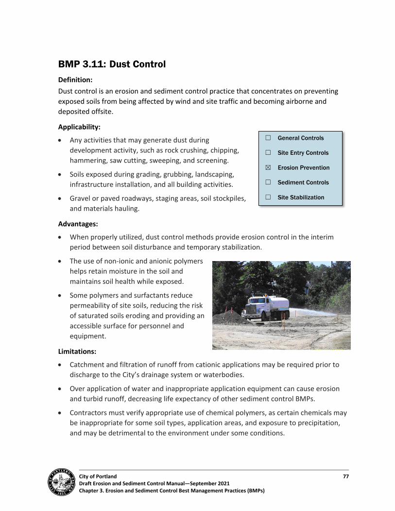
City of Portland 77 Draft Erosion and Sediment Control Manual—September 2021 Chapter 3. Erosion and Sediment Control Best Management Practices (BMPs)
BMP 3.11: Dust Control Definition: Dust control is an erosion and sediment control practice that concentrates on preventing exposed soils from being affected by wind and site traffic and becoming airborne and deposited offsite.
Applicability:
• Any activities that may generate dust during development activity, such as rock crushing, chipping, hammering, saw cutting, sweeping, and screening.
• Soils exposed during grading, grubbing, landscaping, infrastructure installation, and all building activities.
• Gravel or paved roadways, staging areas, soil stockpiles, and materials hauling.
Advantages:
• When properly utilized, dust control methods provide erosion control in the interim period between soil disturbance and temporary stabilization.
• The use of non-ionic and anionic polymers helps retain moisture in the soil and maintains soil health while exposed.
• Some polymers and surfactants reduce permeability of site soils, reducing the risk of saturated soils eroding and providing an accessible surface for personnel and equipment.
Limitations:
• Catchment and filtration of runoff from cationic applications may be required prior to discharge to the City’s drainage system or waterbodies.
• Over application of water and inappropriate application equipment can cause erosion and turbid runoff, decreasing life expectancy of other sediment control BMPs.
• Contractors must verify appropriate use of chemical polymers, as certain chemicals may be inappropriate for some soil types, application areas, and exposure to precipitation, and may be detrimental to the environment under some conditions.
☐ General Controls
☐ Site Entry Controls
☒ Erosion Prevention
☐ Sediment Controls
☐ Site Stabilization
City of Portland 78 Draft Erosion and Sediment Control Manual—September 2021 Chapter 3. Erosion and Sediment Control Best Management Practices (BMPs)
May Not Be Used:
• In a manner that lends to or causes erosion, turbid runoff, or a violation of water quality regulations.
• Water as dust control agent must not be used in excess of seven days where temporary or permanent stabilization BMPs must be applied.
Most Effective When Used With:
• Administrative controls such as a soil disturbance phasing plan, wind speed monitoring, soil disturbing activity restrictions, on site traffic control, and speed limit restrictions.
• Damp sweeping on impervious surfaces.
• Vegetative or structural wind breaks.
• Surface roughening.
• Woven geotextiles under gravel haul roads, staging areas, and stabilized site exits.
Purpose: To prevent exposed and weathered soil from becoming air borne and leaving the site by promoting binding and cohesion of soil particles and retention of moisture. To provide temporary erosion and sediment control in the dry season between initial disturbance and temporary stabilization application.
• Planning Considerations - Dust control may not be used on streets or other impervious surfaces that discharge
to the City’s drainage system or UIC without block-off of receiving basins and full recovery of accumulated water.
- Using water as a dust control agent is NOT a form of temporary stabilization. - Phase the project so that the least amount of soil is exposed at one time. - Use of cationic chemicals may require prior approval, additional treatment facilities,
testing and monitoring, and discharge permits. - Chemical stabilizers typically require a minimum curing time and temperature.
Evaluate weather conditions and project mobilization timing. - If using water as dust control, consider site slopes, soil type, effectiveness, and cost
of repeated re-application.
City of Portland 79 Draft Erosion and Sediment Control Manual—September 2021 Chapter 3. Erosion and Sediment Control Best Management Practices (BMPs)
• Design Specifications - To the extent practicable, allow as much vegetation, trees, and large shrubs to
remain on site during the grading process. This creates windbreaks and reduces the amount of exposed soil.
- Re-establish vegetation as soon as possible. - Between October 1 and April 30, all denuded sites must be provided with either
temporary or permanent soil stabilization as soon as practicable, but in no case more than two days after ground disturbing activity occurs.
- Between May 1 and September 30, temporary erosion and sediment control BMPs to reduce dust and sediment transport must be applied as soon as practicable, but in no case more than 7 days after ground disturbing activity occurs.
- Hydraulically applied surfactants, polymers, tackifiers, seed, mulches, rolled erosion control products, and geotextiles are preferred dust control methods.
- Use administrative controls such as a soil disturbance phasing plan, wind speed monitoring, soil disturbing activity restrictions, on site traffic control, and speed limit restrictions.
Maintenance Requirements: Reapply chemicals and polymers as needed per manufacturer’s recommendation. Reapply water regularly prior to dust generating activities.

City of Portland 80 Draft Erosion and Sediment Control Manual—September 2021 Chapter 3. Erosion and Sediment Control Best Management Practices (BMPs)
BMP 3.12: Stabilized Construction Access Detail 3.12-A: Stabilized Construction Access
Definition: A stabilized construction site entrance/exit is a rock (stone, gravel) pad, or approved manufacturer alternative, designed to remove sediment from vehicles leaving the work zone and entering offsite areas, such as public roadways and public or private parking lots. Paved driveways may be used in lieu of stabilized construction access.
Applicability: At any construction site where traffic will be leaving the site and moving directly onto public roads, paved areas, or other approved access points.
Advantages:
• Reduces traffic hazards caused by debris on public roadway.
• Reduces sediment on roadways that can wash into the storm sewer system.
• Reduces public nuisance.
Limitations:
• Requires periodic top dressing with additional stones.
• Stabilized construction exits may not be completely effective against preventing the deposition of sediments onto paved surfaces. To further reduce the chance of these sediments polluting stormwater runoff, sweeping of the paved area adjacent to the stabilized site exit is recommended.
• Only effective if erosion and sediment control are employed elsewhere on site and at all entrances/exits with significant construction traffic.
• Entrances must not be located within tree protection fencing required by Title 11, Trees, Title 33, Planning & Zoning, or by land use review conditions of approval without a permit revision. In some cases, a report from a certified arborist may be required for permit revision approval.
• Alternative BMPs such as geotextile mud mats, rumble grates, and other manufactured, no-dig options must be utilized near tree protection zones.
☐ General Controls
☒ Site Entry Controls
☐ Erosion Prevention
☐ Sediment Controls
☐ Site Stabilization

City of Portland 81 Draft Erosion and Sediment Control Manual—September 2021 Chapter 3. Erosion and Sediment Control Best Management Practices (BMPs)
May Not Be Used:
• Adjacent to streetcar tracks.
• Across streams and other drainage channels.
Most Effective When Used With:
• Wheel wash structures and equipment
• Dust control
Purpose: To contain sediments onsite and minimize the amount of mud, dirt, rocks, etc. transported onto roads by motor vehicles or stormwater runoff.
• Planning Considerations - A stabilized construction entrance/exit must be installed prior to any vehicles or
materials entering the site. No vehicles can exit the site until a stabilized rock exit is established.
- The need for the construction exit diminishes when vehicles are no longer entering and exiting the site. The construction exit may be removed if construction activities have ceased, a permanent pad or surface has been established, light and heavy construction traffic has ceased or no longer needs to enter the site, or another exit has been established. A construction exit must not be removed without the proper approval and authorization of an inspector.
- Once an exit has been established, temporary or permanent groundcover must be promptly established.
- Note: Construction exit materials can be easily recycled, washed, or reused, and recycling or reuse is encouraged.
• Design Specifications - The rock pad must be at least 8 inches thick and 50 feet long. Width must be the full
width of the vehicle ingress and egress area. (A 20-foot minimum pad length may be acceptable for one- and two-family construction sites.)
- Subgrade reinforcement geotextile must be used under gravel pads for all construction except one- or two-family residences on existing lots of record.
- Sediment control BMPs such as wattles and sediment fence must be used to protect construction exits from siltation from adjoining bare soil areas.
- Washed gravel filter berms must be constructed across onsite traffic wheel paths to capture and retain sediment. o Berms must be 1 foot high with 33 percent (1V:3H) side slopes, constructed of ¾-
inch to 3-inch crushed rock with less than 5 percent fines.

City of Portland 82 Draft Erosion and Sediment Control Manual—September 2021 Chapter 3. Erosion and Sediment Control Best Management Practices (BMPs)
o Berms must be inspected regularly, and accumulated sediment removed, with rock added or replaced as needed.
o Berms must be spaced as follows: Every 300 feet on slopes less than 5 percent Every 200 feet on slopes between 5 and 10 percent Every 100 feet on slopes greater than 10 percent
- Material must be “clean” (less than 5 percent passing the US Standard No. 200 sieve).
- Material must be at least 1½ inch diameter on all sites. Larger rock (2 to 6 inches) is necessary for industrial, commercial, and subdivision sites or in conjunction with wheel wash facilities.
- Recycled aggregate consisting of crushed Portland cement concrete and crushed or ground asphaltic concrete may be acceptable if the material meets the gradation specified in Section 00280.16(a) of the City Standard Specifications. The recycled material must be durable and free of deleterious material, including but not limited to, vegetative matter, wood, lightweight pieces, insulation, gypsum, brick, glass, and metal, and must meet the durability requirements described for coarse aggregates in Section 205.2.12 of the City of Portland Standard Construction Specifications.
- Manufactured entry products and systems must be used only for the purposes intended by the manufacturer and installed per manufacturer specifications. Product documentation must be kept onsite to ensure proper installation.
• Installation Tips and Specifications - Install the construction exit as the first site BMP after any exclusion zones have been
identified and fenced or otherwise protected. - Install in locations where permanent roadways and driveways will be located. - Install multiple layers of geotextile fabric and rock so that rock can be easily
collected for reuse as subbase material under a driveway. - Install turnouts or flares as required to accommodate large equipment turning
radiuses. - If possible, locate entry on upslope side of lot to avoid concentrating and diverting
runoff into the street. - Consider use of multiple entries to access large or difficult sites. - Add a wheel wash area as required.

City of Portland 83 Draft Erosion and Sediment Control Manual—September 2021 Chapter 3. Erosion and Sediment Control Best Management Practices (BMPs)
Maintenance Requirements: - Repair and/or cleanout any structures used to trap sediment. - Flatten any depressions that may collect stormwater and material runoff. - The construction exit must be inspected weekly for Simple Sites, daily for Special
Sites, and after a significant rain event for all sites. - The exit must be maintained in a condition that will prevent tracking or flow of
sediment onto public rights-of-way or other hard impervious surfaces. This may require periodic top-dressing with additional material or washing and reworking the existing material when the void space between rocks becomes filled.
- All materials spilled, dropped, washed, or tracked from vehicles onto roadways or into the stormwater collection system must be removed or cleaned up immediately, and no later than end of the work day.
- The use of water trucks to wash the material off the roadway is not allowed. Water trucks may be used immediately before sweepers or vacuum systems to loosen sediment if discharge to the storm sewer and drainage system does not occur.
- Power washing of sidewalks, driveways, curb line, and right-of-way is not allowed. - If sediment is tracked offsite, additional BMPs must be implemented. These BMPs
may include washing wheels before vehicles leave the site or other construction techniques and work operation modifications. Wheel washing must be done on the rock pad or in an approved wheel wash structure located onsite. The wheels must be washed before crossing the rock pad to leave the site. (See BMP 3.13: Wheel Wash Structures and Equipment.)
Signs of Failure–Stabilized Construction Access Symptoms Potential Cause Suggested Solution Tracking sediment into the street
• Rock contaminated or insufficient.
• Lack of proper maintenance.
• Add larger rock, increase depth of rock, or stabilize a larger area.
• Add a wheel wash facility. • Physically remove surface mud from tires.
Dust generation • Lack of moisture on site roads.
• Friable soils onsite.
• Add additional rock or lengthen drive. • Turnover rock or remove accumulated sediment. • Use a water truck to keep dust down (control
amount and type of spray to minimize erosion). • Use a wetting agent on roadways. (See BMP 3.11:
Dust Control)

City of Portland 84 Draft Erosion and Sediment Control Manual—September 2021 Chapter 3. Erosion and Sediment Control Best Management Practices (BMPs)
BMP 3.13: Wheel Wash Structures and Equipment Detail 3.13-A: Wheel Wash Structure
Definition: A wheel wash structure removes sediment from the tires and undercarriages of vehicles when they are leaving a work zone and entering offsite areas. Note: in many cases cattle guards and/or rumble strips may be sufficient for removing sediment from vehicle tires. This BMP refers to more robust structural wheel wash devices with contained wash water and manual wheel washes, which utilize rock entrances in conjunction with steel plates and a water hose.
Applicability:
Wheel wash facilities are required when other BMPs prove inadequate to prevent mud or sediment from being tracked off the construction site.
Advantages:
• More effective at removal of sediment from vehicles than stabilized construction entrance/exits alone.
• Useful for high traffic volume or long duration projects.
• Reduces traffic hazards caused by debris on public roadways.
Limitations:
• Requires discharge authorization from the Bureau of Environmental Services.
• Requires a source of wash water and treatment of sediment laden water.
• Requires a turnout or doublewide entrance/exit to avoid entering vehicles having to drive through wash area.
• May fill with sediment quickly and require frequent maintenance.
May Not Be Used: N/A
Most Effective When Used With:
• Stabilized construction site entrance/exit
• Dust control
☐ General Controls
☒ Site Entry Controls
☐ Erosion Prevention
☐ Sediment Controls
☐ Site Stabilization
City of Portland 85 Draft Erosion and Sediment Control Manual—September 2021 Chapter 3. Erosion and Sediment Control Best Management Practices (BMPs)
Purpose: To remove mud and sediment from tires and undercarriages of vehicles moving off the site. The sediment is trapped in the wheel wash structure, and wash water is reclaimed, infiltrated, or discharged in an approved manner.
• Planning Considerations - When a wheel wash facility is required because of sediment tracking, no further
traffic is allowed until the facility is constructed and shown to function. - The wheel wash may be removed when construction activities have ceased, a
permanent pad or surface has been established, or light and heavy construction traffic has ceased or no longer needs to enter the site.
- Any soils exposed by removing the wheel wash facility must be promptly covered by temporary or permanent groundcover.
• Design Specifications - Mobile wheel wash units and bump ramp-type products are allowed but must be
installed in accordance with the manufacturer’s recommendations. - The structure must be established on a grade not greater than 1 percent. - The wash must have a minimum 50-foot-long run-out area for vehicles leaving the
wash. The run-out area must consist of stabilized construction site entrance/exit rock.
- The wash must be at least 18 inches deep, with a constant minimum water-pool depth of at least 12 inches.
- Wheel washes must be constructed with a layer of filter fabric covered by 12 inches of compacted, crushed rock or as designed by a licensed engineer.
- Wash water must be drained through a sediment-trapping structure before leaving the construction site. All offsite discharges require prior approval from the BES. For information about treatment and disposal of wastewater, contact BES Source Control.
- Discharge of turbid and discolored water is prohibited by PCC Title 17.
• Installation Tips - Provide separate site entry and exits on large sites and use large rock (4- to 6-inch
gabion rock) at the approach and the drive-out space for the wheel wash. - Install the facility near a water source and a sanitary connection. - Consider a recycled pumped system or mobile units.
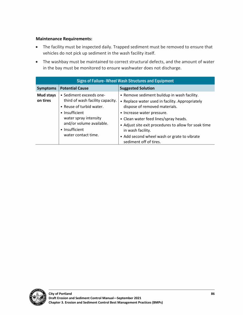
City of Portland 86 Draft Erosion and Sediment Control Manual—September 2021 Chapter 3. Erosion and Sediment Control Best Management Practices (BMPs)
Maintenance Requirements:
• The facility must be inspected daily. Trapped sediment must be removed to ensure that vehicles do not pick up sediment in the wash facility itself.
• The washbay must be maintained to correct structural defects, and the amount of water in the bay must be monitored to ensure washwater does not discharge.
Signs of Failure–Wheel Wash Structures and Equipment Symptoms Potential Cause Suggested Solution Mud stays on tires
• Sediment exceeds one-third of wash facility capacity.
• Reuse of turbid water. • Insufficient
water spray intensity and/or volume available.
• Insufficient water contact time.
• Remove sediment buildup in wash facility. • Replace water used in facility. Appropriately
dispose of removed materials. • Increase water pressure. • Clean water feed lines/spray heads. • Adjust site exit procedures to allow for soak time
in wash facility. • Add second wheel wash or grate to vibrate
sediment off of tires.
City of Portland 87 Draft Erosion and Sediment Control Manual—September 2021 Chapter 3. Erosion and Sediment Control Best Management Practices (BMPs)
BMP 3.14: Sidewalk Subgrade Barriers Detail 3.14-A: Sidewalk Subgrade Barriers
Definition: A sidewalk subgrade barrier is a perimeter sediment control BMP that uses subgrade gravel as a temporary trap for sediment-laden runoff.
Applicability: Typically, one- and two-family residential construction sites, where the site slopes to a street with planned but unbuilt sidewalks and site slopes are less than 5 percent.
Advantages:
• Easy to install and economical.
• Can retain suspended solids.
Limitations:
• May not be acceptable by local jurisdiction for sub-base material when pouring sidewalk.
• May require additional sediment control BMPs depending on soil type.
• May need periodic maintenance for removal of accumulated sediment.
May Not Be Used:
• By themselves on slopes greater than 5 percent.
• In areas of high runoff volume.
Most Effective When Used With:
• Stabilized construction site entrance/exit
• Temporary sediment control (silt) fence
☐ General Controls
☐ Site Entry Controls
☐ Erosion Prevention
☒ Sediment Controls
☐ Site Stabilization
City of Portland 88 Draft Erosion and Sediment Control Manual—September 2021 Chapter 3. Erosion and Sediment Control Best Management Practices (BMPs)
Purpose: To minimize the transport of sediment from a construction site by using the sidewalk subgrade gravel as a temporary trap for sediment-laden runoff.
• Planning Considerations - Subgrade gravel may not meet the City’s specifications for sidewalk concrete
placement if too much sediment has infiltrated the rock. Routine sediment removal and onsite erosion prevention BMPs will help protect reuse of these gravels. The permittee must weigh the benefits of eliminating sediment barriers versus the possibility that the City may reject the subgrade gravel. It may be cost effective to wash and reuse materials.
• Design Specifications - Excavate a minimum of 8 inches behind existing curbing. Line with a geotextile
fabric. Backfill with a minimum of 4 inches of gravel, leaving a 4-inch air gap/freeboard as capture depth behind the curb.
- Sidewalk subgrade gravel must be in place during the entire construction period, from the time of initial site clearing/grading through establishment of permanent site cover. If the sidewalk concrete is to be poured before permanent site cover is established, approved sediment barriers must be installed before pouring concrete.
• Installation Tips and Specifications - Excavate to finish subgrade, so fabric and gravel may remain permanently in place.
Remove contaminated material adequate to pave sidewalk. - Use with silt fence, mulch, or gravel behind the curb or at property line. - For cross slopes greater than 5 percent and at property corners, add winged sections
to silt fence behind curb.
Maintenance Requirements:
• Remove sediment when it accumulates to within 2 inches of the top of the curbing. All materials spilled, dropped, washed, or tracked from vehicles onto roadways or into the stormwater collection system must be removed or cleaned up immediately. The use of water trucks to remove this material is not permitted under any circumstances.
• Replace rock when surface voids in gravel are no longer visible. This may require periodic top dressing with additional gravel or rock, or washing and reworking the existing material, as conditions demand.
• If the sidewalk subgrade gravel does not provide an effective filter and sediment is leaving the construction site, additional BMPs must be applied. These may include replacement of gravel or installation of additional sediment barriers.

City of Portland 89 Draft Erosion and Sediment Control Manual—September 2021 Chapter 3. Erosion and Sediment Control Best Management Practices (BMPs)
Signs of Failure–Sidewalk Subgrade Barriers Symptoms Potential Cause Suggested Solution Sediment in road
• Sediment has overtopped subgrade capture area.
• Concentrated flow from above the subgrade area.
• Remove sediment buildup. • Mulch or prevent erosion from contributing
areas. • Pipe away concentrated stormwater flows. • Use a spreader to disperse concentrated flows
evenly across the site.

City of Portland 90 Draft Erosion and Sediment Control Manual—September 2021 Chapter 3. Erosion and Sediment Control Best Management Practices (BMPs)
BMP 3.15: Temporary Sediment Control (Silt) Fence Detail 3.15-A: Temporary Sediment Control Fence
Definition: Temporary sediment barrier consisting of geotextile fabric stretched across and attached to supporting posts, adequate to treat flow depths consistent with overland or sheet flow.
Applicability:
• Downslope of disturbed areas where runoff occurs as sheet runoff.
• At the toe of soil stockpiles.
• At intervals along the contours of large, disturbed areas.
• At grade breaks exceeding 20 percent, up to 50 percent.
Advantages:
• Can retain a large volume of sediment.
• Relatively inexpensive and readily available.
Limitations:
• Sediment fences are most effective for trapping granular or coarse materials and not be relied on to reduce turbidity.
• Not applicable to concentrated flows.
• Requires frequent maintenance and inspection.
• Removal of sediment fence can compromise vegetative stabilization.
• Must be disposed of after single use.
• Sediment fences must not be located within tree protection fencing required by Title 11, Trees, Title 33, Planning & Zoning, or by land use review conditions of approval without a permit revision. In some cases, a report from a certified arborist may be required for permit revision approval.
☐ General Controls
☐ Site Entry Controls
☒ Erosion Prevention
☐ Sediment Controls
☐ Site Stabilization

City of Portland 91 Draft Erosion and Sediment Control Manual—September 2021 Chapter 3. Erosion and Sediment Control Best Management Practices (BMPs)
May Not Be Used:
• By themselves on slopes steeper than 50 percent. Sediment fences must be used in conjunction with upslope stormwater and sediment control practices.
• Across streams, drainage channels, or other areas of concentrated flow.
• For work on paved streets or other paved surfaces.
• Upslope of disturbance areas. Surrounding the entire site with sediment fence is neither required nor recommended.
Most Effective When Used: Downslope of other BMPs such as filtration bags and socks or fiber rolls and wattles.
Purpose: To minimize the transport of sediment from a construction site by providing a temporary physical barrier to sediment movement and reducing runoff velocities. Sediment fences have limited capacity to filter sediment from flows.
• Planning Considerations - Sediment fences may be used in combination with chain link fencing or wire backing - For additional structural support, fencing should be placed directly down slope from
the temporary sediment fence for additional structural control. - Biofilter bags, fiber rolls, or coarse mulch berms are effective up slope of the
sediment fence to provide additional sediment retention and reduce runoff velocity.
• Design Specifications - A trench must be cut along slope contours and around stockpiles for sediment fence
installation. Filter fabric fence must have a minimum vertical burial of 6 inches. All excavated material from filter fabric fence installation must be firmly compacted along the entire trenched area on the uphill side of and against the fence.
- Standard or heavy-duty filter fabric fence must have manufactured stitched loops to fit 2-inch x 2-inch installation posts. Stapled fence products are not allowed. Stitched loops and slopes must be installed so they are facing the uphill side of the slope, with posts spaced a maximum of 6 feet apart (see Detail Drawing 3.15-A).
- Where practical, the filter fabric must be purchased in a continuous roll the length of the barrier to avoid use of joints. When joints are necessary, 2-inch by 2-inch posts must be interlocked with each other and attached securely together.
- Maximum sheet or overland flow path length to sediment fences must be 100 linear feet for slopes steeper than 50 percent and 50 feet for slopes less than 50 percent. The size of the drainage area must be no more than 1/4 acre for each 100 lineal feet of fence. Ends of fence lines must be angled upslope in an arcing fashion. Wings may need to be added for long lines running downslope to allow for slowing of surface
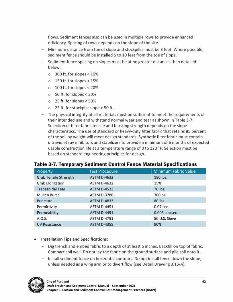
City of Portland 92 Draft Erosion and Sediment Control Manual—September 2021 Chapter 3. Erosion and Sediment Control Best Management Practices (BMPs)
flows. Sediment fences also can be used in multiple rows to provide enhanced efficiency. Spacing of rows depends on the slope of the site.
- Minimum distance from toe of slope and stockpiles must be 3 feet. Where possible, sediment fence should be installed 5 to 10 feet from the toe of slope.
- Sediment fence spacing on slopes must be at no greater distances than detailed below: o 300 ft. for slopes < 10% o 150 ft. for slopes < 15% o 100 ft. for slopes < 20% o 50 ft. for slopes < 30% o 25 ft. for slopes < 50% o 25 ft. for stockpile slope > 50 ft.
- The physical integrity of all materials must be sufficient to meet the requirements of their intended use and withstand normal wear and tear as shown in Table 3-7. Selection of filter fabric tensile and bursting strength depends on the slope characteristics. The use of standard or heavy-duty filter fabric that retains 85 percent of the soil by weight will meet design standards. Synthetic filter fabric must contain ultraviolet ray inhibitors and stabilizers to provide a minimum of 6 months of expected usable construction life at a temperature range of 0 to 120 °F. Selection must be based on standard engineering principles for design.
Table 3-7. Temporary Sediment Control Fence Material Specifications Property Test Procedure Minimum Fabric Value Grab Tensile Strength ASTM D-4632 180 lbs. Grab Elongation ASTM D-4632 15% Trapezoidal Tear ASTM D-4533 70 lbs. Mullen Burst ASTM D-3786 300 psi Puncture ASTM D-4833 80 lbs. Permittivity ASTM D-4491 0.07 sec Permeability ASTM D-4491 0.005 cm/sec A.O.S. ASTM D-4751 50 U.S. Sieve UV Resistance ASTM D-4355 90%
• Installation Tips and Specifications: - Dig trench and embed fabric to a depth of at least 6 inches. Backfill on top of fabric.
Compact soil well. Do not lay the fabric on the ground surface and pile soil onto it. - Install sediment fence on horizontal contours. Do not install fence down the slope,
unless needed as a wing arm or to divert flow (see Detail Drawing 3.15-A).
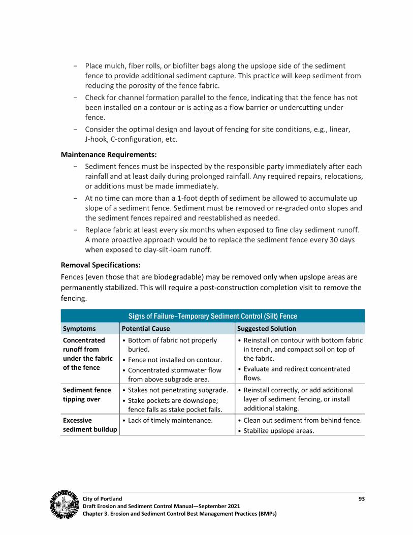
City of Portland 93 Draft Erosion and Sediment Control Manual—September 2021 Chapter 3. Erosion and Sediment Control Best Management Practices (BMPs)
- Place mulch, fiber rolls, or biofilter bags along the upslope side of the sediment fence to provide additional sediment capture. This practice will keep sediment from reducing the porosity of the fence fabric.
- Check for channel formation parallel to the fence, indicating that the fence has not been installed on a contour or is acting as a flow barrier or undercutting under fence.
- Consider the optimal design and layout of fencing for site conditions, e.g., linear, J-hook, C-configuration, etc.
Maintenance Requirements: - Sediment fences must be inspected by the responsible party immediately after each
rainfall and at least daily during prolonged rainfall. Any required repairs, relocations, or additions must be made immediately.
- At no time can more than a 1-foot depth of sediment be allowed to accumulate up slope of a sediment fence. Sediment must be removed or re-graded onto slopes and the sediment fences repaired and reestablished as needed.
- Replace fabric at least every six months when exposed to fine clay sediment runoff. A more proactive approach would be to replace the sediment fence every 30 days when exposed to clay-silt-loam runoff.
Removal Specifications: Fences (even those that are biodegradable) may be removed only when upslope areas are permanently stabilized. This will require a post-construction completion visit to remove the fencing.
Signs of Failure–Temporary Sediment Control (Silt) Fence Symptoms Potential Cause Suggested Solution Concentrated runoff from under the fabric of the fence
• Bottom of fabric not properly buried.
• Fence not installed on contour. • Concentrated stormwater flow
from above subgrade area.
• Reinstall on contour with bottom fabric in trench, and compact soil on top of the fabric.
• Evaluate and redirect concentrated flows.
Sediment fence tipping over
• Stakes not penetrating subgrade. • Stake pockets are downslope;
fence falls as stake pocket fails.
• Reinstall correctly, or add additional layer of sediment fencing, or install additional staking.
Excessive sediment buildup
• Lack of timely maintenance. • Clean out sediment from behind fence. • Stabilize upslope areas.

City of Portland 94 Draft Erosion and Sediment Control Manual—September 2021 Chapter 3. Erosion and Sediment Control Best Management Practices (BMPs)
BMP 3.16: Filtration Bags and Socks Detail 3.16-A: Filtration bags and Socks: Temporary Inlet Protection Detail 3.16-B: TO BE CREATED Detail 3.16-C: Filtration Bags and Socks: Slope Installations
Definition: A series of contained filtration materials that can be used to slow flows and provide settling of sediments in runoff. This group includes biofilter bags, gravel socks, sandbags, compost socks, and wood fiber bags. Bags and socks are made in various sizes of plastic mesh or geotextile cloth and filled with a variety of organic or inorganic materials designed to filter and detain flows and sediment.
Applicability:
• As temporary protection of existing catch basins and/or gutter inlets.
• As a perimeter control BMP.
• For flow control as a check dam.
• As an alternative to sediment fence wings.
Advantages:
• Relatively low cost, and simple to install.
• Can be transported and installed by hand.
Limitations:
• Plastic mesh bags are not allowed for use in public rights-of-way or traffic areas. Only solid surface geotextile bags maybe used in traffic areas.
• Generally effective for only a few months and can be easily damaged by construction equipment.
• May become clogged with sediment and require frequent maintenance.
• Biobags/woodchip bags are not allowable at the toe of soil stockpiles, as perimeter control, or as an alternative to sediment fence wings.
• Placement of biobags and rolls around catch basins must not cause stormwater flows to bypass the intended receiving basin.
☐ General Controls
☐ Site Entry Controls
☐ Erosion Prevention
☒ Sediment Controls
☐ Site Stabilization

City of Portland 95 Draft Erosion and Sediment Control Manual—September 2021 Chapter 3. Erosion and Sediment Control Best Management Practices (BMPs)
May Not Be Used:
• In high-flow areas.
• For catch basin protection without inlet inserts.
• As an alternative to sediment fence.
• In locations that will impede traffic in bike lanes, or as an alternative to curb inlet protection devices.
Most Effective When Used With: Mulch
Purpose: To minimize the transport of sediment from a construction site by providing a temporary physical barrier to sediment and reducing runoff velocities. Filtration bags and socks provide stormwater flow attenuation and an area for sedimentation of larger soil particles.
• Planning Considerations - Filtration bags and socks are generally effective for only a few months and must be
either replaced or considered a temporary solution. - Fill material may be incorporated as mulch after completion of site work if approved
by the City. Removal will necessitate a post-construction site visit. The bags or socks must be disposed of at a local recycling or solid waste disposal facility.
• Design Specifications - Fill material must be clean, 100 percent recycled wood, sand, gravel, or compost
product. Bag size can vary, but bags are generally 18 to 20 inches long and weigh approximately 45 pounds. Bags are usually made of geotextile fabrics or open ½-inch plastic mesh.
- In traffic areas, bags must be made of geotextile material. - Bags used on pervious surfaces must be staked into place. Stakes must be installed
as shown in the notes on BMP detail drawings.
• Installation Tips and Specifications - Bags and socks are best used in low-exposure/low-sediment load areas. - Ensure that no gaps exist under or between bags that could bypass flows. Overlap
bags and socks whenever possible.

City of Portland 96 Draft Erosion and Sediment Control Manual—September 2021 Chapter 3. Erosion and Sediment Control Best Management Practices (BMPs)
Maintenance Requirements:
• Bags and socks must be inspected per Title 10 requirements.
• Filter bags and socks must be replaced as soon as degradation or damage is observed, at least every 3 months and more often if necessary, to maintain their effectiveness.
• Sediment depth must not accumulate to more than one-third the height of the bag or sock. Remove sediment buildup or replace backs or socks when one-third of capacity is full.
• Inspect for clogging and damage often; high flows, vehicle damage, and vandalism can damage bags and limit performance.
Removal Specifications:
• Sediment must be removed or re-graded onto the slope.
• Once the upslope area is stabilized, bags and socks must be removed.
Signs of Failure–Filtration Bags and Socks Symptoms Potential Cause Suggested Solution Concentrated runoff or sediment flows are coming around or under bags
• Insufficient materials. • Insufficient
stake down during installation.
• Add additional materials and align to contain flows.
• Reinstall with proper staking and entrenchment.
Sediment is overwhelming bags
• Lack of upslope BMPs. • Inadequate maintenance.
• Add erosion prevention or other sediment control BMPs.
• Clean sediment from behind bags or rolls.

City of Portland 97 Draft Erosion and Sediment Control Manual—September 2021 Chapter 3. Erosion and Sediment Control Best Management Practices (BMPs)
BMP 3.17: Fiber Rolls and Wattles Detail 3.17-A: Fiber Rolls and Wattles: Slope Installation Detail 3.17-B: Fiber Rolls and Wattles: Ditch/Swale Installation
Definition: Fiber rolls are dense, vegetated fiber tubes that detain sediments and runoff flows commonly made of rice and coconut fibers and provide a planting medium for plug or potted plants. Wattles are plastic or rope mesh rolls that are usually filled with straw. Wattles come in various lengths and are a good alternative to bag and sock products.
Applicability:
• As a check dam in drainage ditches and/or swales.
• As flow control and for sediment control on paved surfaces.
• On either side of a sediment fence line.
• Fiber rolls can filter; wattles are intended as barriers.
Advantages:
• Fully biodegradable fiber rolls do not need to be removed.
• Easier to deploy than sediment fences on steep slopes.
• Lightweight and requires minimal ground disturbance to install.
Limitations:
• Shallow trenching for installation may be difficult on rocky ground.
• Trenching is not allowed within root protection zones of trees required to be preserved by Title 11 or Title 33 unless approved per the requirements of those titles.
• Low sediment retaining capacity–may require frequent maintenance.
May Not Be Used: In high-flow areas.
Most Effective When Used With:
• Vegetative cover
• In series with other sediment and flow control BMPs
• Bioengineered stabilization
☐ General Controls
☐ Site Entry Controls
☒ Erosion Prevention
☒ Sediment Controls
☐ Site Stabilization

City of Portland 98 Draft Erosion and Sediment Control Manual—September 2021 Chapter 3. Erosion and Sediment Control Best Management Practices (BMPs)
Purpose: To minimize the transport of sediment by providing a temporary physical barrier to sediment and reducing runoff velocities, to help stabilize the ground surface and provide a bed for planting, and to shorten the length over which runoff can flow uninterrupted down a slope.
• Planning Considerations - The use of fiber rolls constructed with fully biodegradable materials does not require
disposal and is therefore recommended.
• Design Specifications - Prepare the slope before the wattle installation is started. - Surface irregularities must be smoothed as work progresses. - Dig small trenches across the slope on contour to place rolls in. The trench must be
deep enough to accommodate one-third the thickness of the roll. - Start building trenches and install rolls from the bottom of the slope and work up. - Install rolls perpendicular to water movement, parallel to the slope contour. - Lay the roll along the trenches, fitting it snugly against the soil. Make sure no gaps
exist between the soil and the straw wattle. - Overlap roll ends 6” to ensure no gaps in protection - Stakes must be installed as shown in the notes in the BMP detail drawings. - Straw wattles and fiber rolls are typically available in 9”, 12”, and 20” diameter sizes.
Point of installation, amount of predicted sediment loss, and flow rates should be considered when determining the appropriate size.
- If using reusable wattles, install and maintain to manufacturer’s specifications.
• Installation Tips and Specifications - Use fiber rolls up slope or down slope of silt fence to provide added support to the
toe of the fence. - Maintenance is critical. Remove sediment buildup and replace or add additional
fiber rolls when one-third of capacity is full. - Check remaining capacity often since high flows can limit performance and damage
rolls. - Best used in low-exposure/low-sediment load areas. - Check placement and performance often to avoid impacts from vehicle damage
and/or vandalism. - Ensure that no gaps exist under or between rolls that could bypass flows. Overlap
fiber rolls and wattles whenever possible. - Place sandbags over wattles to improve ground contact on impervious surfaces or
use manufactured weighted wattles.

City of Portland 99 Draft Erosion and Sediment Control Manual—September 2021 Chapter 3. Erosion and Sediment Control Best Management Practices (BMPs)
Maintenance Requirements:
• Fiber rolls must be inspected per Title 10 requirements. Repair rills or gullies promptly.
• Sediment depth must not accumulate to more than one-third the height of the fiber roll.
• Sediment must be removed or re-graded onto the slope.
• Fiber rolls may be left onsite as a semi-permanent, biodegradable landscape feature.
Signs of Failure–Fiber Rolls and Wattles Symptoms Potential Cause Suggested Solution Concentrated runoff or sediment flows are coming around or under rolls
• Insufficient materials. • Insufficient stake-down during
installation. • Lack of upslope BMPs.
• Add additional materials and align to contain flows.
• Reinstall with proper staking and entrenchment.
Sediment is overwhelming rolls
• Lack of upslope BMPs. • Inadequate maintenance. • Improper sizing.
• Add erosion prevention or other sediment control BMPs.
• Clean sediment from behind bags or rolls.
• Re-evaluate the diameter of the product and increase size as needed.
City of Portland 100 Draft Erosion and Sediment Control Manual—September 2021 Chapter 3. Erosion and Sediment Control Best Management Practices (BMPs)
BMP 3.18: Vegetated Buffers Detail 3.18-A: Vegetative Buffer
Definition: Vegetated buffers are swaths of established vegetation along the peripheries of the project site that hold soils, acts as a windbreak, and filter surface runoff. They operate in conjunction with other perimeter BMPs (perimeter sediment controls, sediment barriers, sediment control fence, delineation fencing, no-disturbance signage) to provide perimeter controls for the project site.
Applicability:
• Between disturbed areas and streams, wetlands, or other water bodies.
• To control erosion on long slopes.
• As a no-disturbance zone for areas that will be used for infiltration.
• As a no activity zone between staging or processing activities and neighboring residential areas.
Advantages:
• Can provide “polishing” of water before it discharges to a drainageway.
• Promotes infiltration.
• Provides habitat, shade, and visual screening.
• Dissipates energy by reducing velocity of runoff.
• Low maintenance.
Limitations: Protected riparian areas and areas within Environmental, River, or Greenway overlay zones must not be used as a buffer without specific permission from the City.
May Not Be Used:
• As a sediment filtration area that receives sediment discharges.
• As a replacement or alternative to perimeter sediment controls.
☐ General Controls
☐ Site Entry Controls
☒ Erosion Prevention
☐ Sediment Controls
☐ Site Stabilization

City of Portland 101 Draft Erosion and Sediment Control Manual—September 2021 Chapter 3. Erosion and Sediment Control Best Management Practices (BMPs)
Most Effective When Used With:
• Sediment barriers, temporary sediment control (silt) fence, and other perimeter sediment control BMPs
• Delineation fencing, no-disturbance signage
Purpose: To minimize soil movement offsite by wind or surface runoff. May act as a supplemental measure to sediment barriers or sediment control fence.
• Planning Considerations - Constrains work area and equipment movement–work with the contractor to
establish a phased grading plan that includes buffer zones when applicable. - Requires the inspector or contractor to fence or flag the clearing limits and outside
tree and shrub driplines.
• Design Specifications - Vegetation must be at least 1 inch in height and provide 80 percent ground
coverage. Vegetated buffers must be outlined with orange construction fencing before any ground-disturbing activity. Silt fence must not be used in place of construction fencing for this purpose.
- For preservation buffers, designate areas of no disturbance. Clearly mark these areas with flags, fencing, or other visible methods. Ensure that all site workers understand the meaning and use of these areas.
- Buffers must be sized according to Table 3-8.
Table 3-8. Vegetative Buffer Sizing Site Location Minimum Buffer Width Infill or flat site (< 10 percent slope) with less than 100 feet of slope length
10 feet.
Adjacent to waterways or other natural resources
50 feet, 20 percent of the slope length, or as per Environmental, River, Greenway or other zoning requirements, whichever is greater.
Other slopes 10 feet or 20 percent of the slope length, whichever is greater.

City of Portland 102 Draft Erosion and Sediment Control Manual—September 2021 Chapter 3. Erosion and Sediment Control Best Management Practices (BMPs)
• Installation Tips - Ensure that the buffer has densely rooted groundcover materials. - Buffers are best used in low-exposure/low-sediment load areas.
Maintenance Requirements:
• Maintenance is critical. Buffers must not receive sediment discharges or be used as a sediment filtration area.
• Any exposed soils must be immediately reseeded or revegetated, and another form of erosion and sediment control BMP must be used until the dense vegetation is reestablished.
• Buffers are usually permanent features that are preserved prior to construction or are areas of permanent landscaping. Temporary buffers must be removed before placement of final permanent buffer.
Signs of Failure–Vegetated Buffers Symptoms Potential Cause Suggested Solution Concentrated runoff or sediment flows are discharging from buffers
• Insufficiently sized buffers. • Flow is concentrating
and not dissipating across the buffer.
• Add additional width/depth to buffer area. • Install or repair flow-spreading devices to
ensure sheet flow across the buffer. • Provide additional sediment control BMPs
prior to discharge through buffers.

City of Portland 103 Draft Erosion and Sediment Control Manual—September 2021 Chapter 3. Erosion and Sediment Control Best Management Practices (BMPs)
BMP 3.19: Storm Drain Inlet Protection Detail 3.19-A: Storm Drain Inlet Protection Detail 3.19-B: Storm Drain Inlet Insert
Definition: Inlet protections include protective BMPs, such as barriers and/or inserts, intended to minimize sediment entering storm drain systems or catch basins by filtering runoff and retaining sediment before it reaches a drainage inlet or storm sewer system. Inlet protection is a last line of defense before sediment-laden runoff exits the site and enters the storm sewer and drainage system or waterways.
Applicability:
• Any field or street inlet or catch basin or drainage system component that may receive construction-related site runoff.
• Where interior onsite or adjacent storm drain systems are operational before permanent stabilization of the disturbed drainage area.
• Adjacent to and immediately downhill of utility-type construction in existing paved areas with catch basin drainage.
• As a secondary measure downstream of other erosion and sediment control BMPs.
Advantages: Prevents or minimizes sediment from leaving the site and entering the storm drain system.
Limitations:
• May result in ponding of water above the catch basin. Ponding that extends to active roadways may be prohibited, and ponding that overtops the inlet protection may negate the BMPs effectiveness.
• Can be easily dislodged or damaged by vehicle traffic and can be dangerous to bicycles or motorcycles.
☐ General Controls
☐ Site Entry Controls
☐ Erosion Prevention
☒ Sediment Controls
☐ Site Stabilization

City of Portland 104 Draft Erosion and Sediment Control Manual—September 2021 Chapter 3. Erosion and Sediment Control Best Management Practices (BMPs)
May Not Be Used:
• Alone without another site control BMPs.
• In high-traffic or high-flow areas.
Most Effective When Used With: Upslope erosion and sediment control practices such as rolled erosion control products, temporary/permanent vegetative cover, etc.
Purpose: To minimize sediment entering storm drain systems or catch basins prior to permanent stabilization of disturbed areas. Inlet protection may consist of inlet barriers, inlet inserts, or a combination of both.
• Planning Considerations - Inlet barriers typically surround the inlet to prevent sediment from entering. - Barriers can be made from plastic, geotextiles, or aggregate materials. - Inlet inserts are devices designed to hang down into a catch basin or inlet and trap
sediment and/or filter construction and stormwater flows entering the inlet. Inserts can include bags, racks, baskets, or other devices made from filter fabric, wire mesh, metal plates, various types of plastic products, and combinations of these and other materials.
- Barriers and inlet inserts must be manufactured products. Site-built protection must not be used except in emergencies until other products can be obtained.
- Improper removal or lack of maintenance may introduce captured sediment into the storm drain system.
- Sediment removal may be difficult under high-flow conditions. Perform maintenance as an ongoing procedure and before anticipated rainfall events.
- Short-circuiting of flow can occur if protection is not properly installed. - Inlet protection must be the last BMP removed from the site after construction and
cleanup are completed and all erosion and sediment control BMPs are removed. - There are many variations of inlet protection available, and new products are
frequently introduced to address the multiple configurations of inlets. Designers should be familiar with new products and the most current methodology.

City of Portland 105 Draft Erosion and Sediment Control Manual—September 2021 Chapter 3. Erosion and Sediment Control Best Management Practices (BMPs)
• Design Specifications - Inlet Barriers
o Inlet barrier methods include, but are not limited to, protection blocks, inlet pillows, filter socks, fiber rolls or wattles, and sandbags.
o Berms may be required to direct drainage to flow through the filters and prevent bypassing of the inlets.
o Wrapped grates must have fabric ends secured under the grate in a way that does not allow the grate to lift and runoff flows to bypass the inlet. This protection technique is allowed only for short-term use (less than 24 hours) and for low-flow protection.
o Filter bags and socks must be replaced at least every 3 months, and more often if necessary, to maintain their effectiveness.
o Additional BMPs may be required to control flows, wash-over, and down-gradient flooding on sloping sites.
- Inlet Inserts o Inlet inserts must be used with additional upslope BMPs, including sweeping of
surfaces; they are not effective when used alone. Inserts must be installed per the manufacturer’s instructions and meet the following criteria:
o Devices must be installed as a point protection or in series as a perimeter sediment control before any site grading activity.
o Installation must not block flows from filtering into the inlet or catch basin. o Devices must be installed without protruding parts that could be a traffic,
worker, or pedestrian hazard. o Retrieval edges, cords, bars, chains, or other mechanisms must be flagged or
marked for retrieval under submerged conditions. o Curb inlet protection devices are required in addition to inlet inserts where
recessed curb inlets are present.
• Installation Tips and Specifications - For field inlets using silt fence protection (see Detail Drawing 3.15-A), use multiple
rows of fencing to enhance protection from construction vehicles. - Ensure that overlap joints in silt fence fabric pieces are appropriately welded or
wrapped. - Consider use of check dams in the gutter drainage area upslope of inlet devices to
enhance sediment removal.
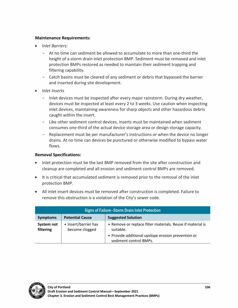
City of Portland 106 Draft Erosion and Sediment Control Manual—September 2021 Chapter 3. Erosion and Sediment Control Best Management Practices (BMPs)
Maintenance Requirements:
• Inlet Barriers: - At no time can sediment be allowed to accumulate to more than one-third the
height of a storm drain inlet protection BMP. Sediment must be removed and inlet protection BMPs restored as needed to maintain their sediment trapping and filtering capability.
- Catch basins must be cleared of any sediment or debris that bypassed the barrier and inserted during site development.
• Inlet Inserts - Inlet devices must be inspected after every major rainstorm. During dry weather,
devices must be inspected at least every 2 to 3 weeks. Use caution when inspecting inlet devices, maintaining awareness for sharp objects and other hazardous debris caught within the insert.
- Like other sediment control devices, inserts must be maintained when sediment consumes one-third of the actual device storage area or design storage capacity.
- Replacement must be per manufacturer’s instructions or when the device no longer drains. At no time can devices be punctured or otherwise modified to bypass water flows.
Removal Specifications:
• Inlet protection must be the last BMP removed from the site after construction and cleanup are completed and all erosion and sediment control BMPs are removed.
• It is critical that accumulated sediment is removed prior to the removal of the inlet protection BMP.
• All inlet insert devices must be removed after construction is completed. Failure to remove this obstruction is a violation of the City’s sewer code.
Signs of Failure–Storm Drain Inlet Protection Symptoms Potential Cause Suggested Solution System not filtering
• Insert/barrier has become clogged
• Remove or replace filter materials. Reuse if material is suitable.
• Provide additional upslope erosion prevention or sediment control BMPs.

City of Portland 107 Draft Erosion and Sediment Control Manual—September 2021 Chapter 3. Erosion and Sediment Control Best Management Practices (BMPs)
BMP 3.20: Filtration Berms Detail 3.20-A: Filtration Berm
Definition: A variety of filtration media can be placed around the perimeter of the construction site as a sediment control berm, with or without a confining sock or bag. These berms are most commonly created of clean gravel and compost. They are usually continuous berms placed by machine.
Applicability: Around a construction site perimeter or base of a stockpile, or as a check dam or slope flow dissipater.
Advantages: Efficient method for sediment removal and runoff velocity reduction.
Limitations:
• Relatively expensive because requires clean gravel or crushed rock rather than on-site materials.
• Can clog with sediment, leading to difficult maintenance and a limited life span.
May Not Be Used:
• Alone without other site control BMPs.
• In high-traffic or high-flow areas.
• On steep slopes.
Most Effective When Used With: Other perimeter sediment control BMPs, such as temporary sediment control (silt) fences.
☐ General Controls
☐ Site Entry Controls
☐ Erosion Prevention
☒ Sediment Controls
☐ Site Stabilization
City of Portland 108 Draft Erosion and Sediment Control Manual—September 2021 Chapter 3. Erosion and Sediment Control Best Management Practices (BMPs)
Purpose: To act as a secondary perimeter sediment control measure.
• Planning Considerations - Filtration berm materials can get clogged just like any other filtration media.
Particular attention must be given to sediment removal in order to preserve berm effectiveness.
• Design Specifications - Filtration berms must be placed per the supplier’s specification per following design
criteria: o Width: Usually 6 to 12 inches, depending on the angle of repose of the material
used. o Height: Usually 4 to 8 inches, depending on the angle of repose of the material
used. o Overlap: If filtration berms are not continuous, berms must overlap at least
8 inches to the upslope side of the berm (the side closest to the soil disturbance).
• Installation Tips and Specifications - Install filtration berms using a designated installation machine specifically designed
for that purpose. It is extremely difficult to install these systems by hand and meet the specification that requires a continuous berm.
- Use filtration berms in conjunction with erosion prevention BMPs for best viability. - Install filtration berms after initial site clearing.
Maintenance Requirements:
• Remove sediment from the upslope side of the berm when sediment reaches no more than one-third the height of the berm.
• Turn over or rake the filtration media surface to break up clogging by sediments and other materials.
• Filtration media must be washed and reused or, depending on the materials, spread and reused onsite.
Removal Specifications: Except for storm drain inlet protection, filtration berms must be the last BMP removed from the active construction site after construction is completed.
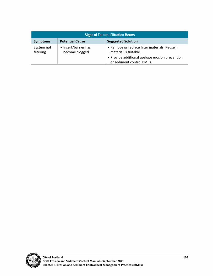
City of Portland 109 Draft Erosion and Sediment Control Manual—September 2021 Chapter 3. Erosion and Sediment Control Best Management Practices (BMPs)
Signs of Failure–Filtration Berms Symptoms Potential Cause Suggested Solution System not filtering
• Insert/barrier has become clogged
• Remove or replace filter materials. Reuse if material is suitable.
• Provide additional upslope erosion prevention or sediment control BMPs.
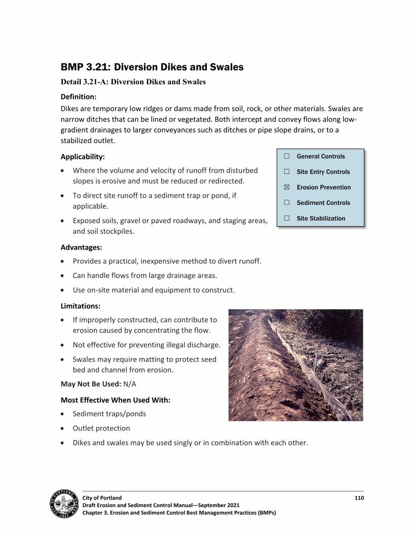
City of Portland 110 Draft Erosion and Sediment Control Manual—September 2021 Chapter 3. Erosion and Sediment Control Best Management Practices (BMPs)
BMP 3.21: Diversion Dikes and Swales Detail 3.21-A: Diversion Dikes and Swales
Definition: Dikes are temporary low ridges or dams made from soil, rock, or other materials. Swales are narrow ditches that can be lined or vegetated. Both intercept and convey flows along low-gradient drainages to larger conveyances such as ditches or pipe slope drains, or to a stabilized outlet.
Applicability:
• Where the volume and velocity of runoff from disturbed slopes is erosive and must be reduced or redirected.
• To direct site runoff to a sediment trap or pond, if applicable.
• Exposed soils, gravel or paved roadways, and staging areas, and soil stockpiles.
Advantages:
• Provides a practical, inexpensive method to divert runoff.
• Can handle flows from large drainage areas.
• Use on-site material and equipment to construct.
Limitations:
• If improperly constructed, can contribute to erosion caused by concentrating the flow.
• Not effective for preventing illegal discharge.
• Swales may require matting to protect seed bed and channel from erosion.
May Not Be Used: N/A
Most Effective When Used With:
• Sediment traps/ponds
• Outlet protection
• Dikes and swales may be used singly or in combination with each other.
☐ General Controls
☐ Site Entry Controls
☒ Erosion Prevention
☐ Sediment Controls
☐ Site Stabilization

City of Portland 111 Draft Erosion and Sediment Control Manual—September 2021 Chapter 3. Erosion and Sediment Control Best Management Practices (BMPs)
Purpose: To intercept and/or divert storm runoff from onsite and offsite drainage areas. To convey runoff from above unprotected slopes or a disturbed site and direct it to a sediment trap, pond, or other approved stabilized outlet.
• Planning Considerations - Dikes and swales may be installed as permanent site drainage control features, while
providing conveyance of temporary development flows. - Multiple dikes and swales may be needed to convey flows. The purpose of the dikes
and swales is to prevent detachment of sediment and to reduce stormwater flows. Their spacing may need to be adjusted in the field to achieve adequate performance.
- As a guideline, dikes and swales must have the maximum horizontal spacing on slopes as shown in Table 3-9:
Table 3-9. Diversion Dike/Swale Spacing Slope Dike/Swale Spacing (ft)
Less than 5 percent 300 5-10 percent 200
10-25 percent 100 25-50 percent 50
• Design Specifications - Maximum grade within interceptor swales is 5 percent, and swales must provide
positive drainage to outlets. Erosion protection materials must be used on exposed soils prior to receiving flows and be specified in submittal plans. Such cover may include grass, rock, or erosion blankets. Check dams must be used to control stormwater flows if design varies from the maximum grade or spacing requirements.
- Grades for drainage parallel to interceptor dikes must be between 0.5 and 1.0 percent, with a maximum flow velocity of 2 fps (feet per second).
- Dike material must be compacted to 90 percent of the maximum dry density determined in accordance with ASTM D1557 (Modified Proctor method).
- Intercepted runoff must be directed to a stabilized area such as a pond, trap, or other holding area. This diversion must be designed so that no erosion occurs from the movement of the additional water volume and flow rate.
- The upslope side of interceptor dikes must provide positive drainage to the dike outlet. Energy dissipation BMPs must be provided as necessary to minimize erosion at dike outlet.
- Construction traffic over dikes and swales must be minimized. When access across or into facilities is unavoidable, repairs must be made as necessary.

City of Portland 112 Draft Erosion and Sediment Control Manual—September 2021 Chapter 3. Erosion and Sediment Control Best Management Practices (BMPs)
- Where necessary, culverts must be provided to ensure diverted water does not cross traffic areas.
• Installation Tips and Specifications - Consider installing the dike or swale as a permanent water quality or conveyance
feature for post-development runoff control. - Establish the dike or swale layout early in the site design and development process,
ideally at the time of mass grading. - Site swales and dikes on terraces of steep slopes and on contour. Allow at least a
10-foot width in the terrace for maintenance access. - Dikes or swales can be temporarily stabilized with vegetation. - Visibly mark locations of dikes and swales with poles or fencing to help protect them
from construction traffic. - Use check dams or other BMPs to control flow rate within dikes and swales. Ensure
that these controls are designed to avoid blowout.
Maintenance Requirements:
• Inspect after every major rainstorm for side and bottom inlet and outlet scour.
• Remove sediment and other debris when one-third of the conveyance or design storage capacity is met.
• Repair any rills or gullies over 2 inches in depth and provide additional flow control upslope of the repair.
• If the dike or swale regularly overflows, increase the capacity and/or frequency of the dikes/swales.
• Minimize construction traffic over temporary dikes and swales. If subjected to construction traffic, the dike or swale must be inspected daily and maintained or repaired as needed.
• Temporary dikes and swales must be graded out at the completion of construction when permanent vegetation has been established.
Removal Specifications: Permanent stormwater management dikes and swales may be used to control runoff during construction but must be refurbished before site closeout.

City of Portland 113 Draft Erosion and Sediment Control Manual—September 2021 Chapter 3. Erosion and Sediment Control Best Management Practices (BMPs)
Signs of Failure–Diversion Dikes and Swales Symptoms Potential Cause Suggested Solution Erosion from Dike/Swale
• Flows are flushing sediment out of the system.
• Flows are eroding the dikes/swales themselves.
• Install additional check dams or energy dissipators.
• Add additional vegetative, blanket, or armoring cover to the sides and bottom of the swale or dike.
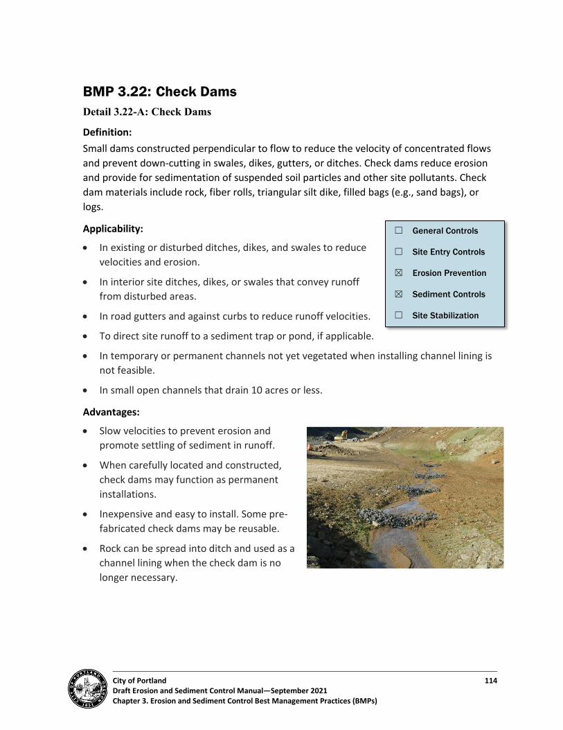
City of Portland 114 Draft Erosion and Sediment Control Manual—September 2021 Chapter 3. Erosion and Sediment Control Best Management Practices (BMPs)
BMP 3.22: Check Dams Detail 3.22-A: Check Dams
Definition: Small dams constructed perpendicular to flow to reduce the velocity of concentrated flows and prevent down-cutting in swales, dikes, gutters, or ditches. Check dams reduce erosion and provide for sedimentation of suspended soil particles and other site pollutants. Check dam materials include rock, fiber rolls, triangular silt dike, filled bags (e.g., sand bags), or logs.
Applicability:
• In existing or disturbed ditches, dikes, and swales to reduce velocities and erosion.
• In interior site ditches, dikes, or swales that convey runoff from disturbed areas.
• In road gutters and against curbs to reduce runoff velocities.
• To direct site runoff to a sediment trap or pond, if applicable.
• In temporary or permanent channels not yet vegetated when installing channel lining is not feasible.
• In small open channels that drain 10 acres or less.
Advantages:
• Slow velocities to prevent erosion and promote settling of sediment in runoff.
• When carefully located and constructed, check dams may function as permanent installations.
• Inexpensive and easy to install. Some pre-fabricated check dams may be reusable.
• Rock can be spread into ditch and used as a channel lining when the check dam is no longer necessary.
☐ General Controls
☐ Site Entry Controls
☒ Erosion Prevention
☒ Sediment Controls
☐ Site Stabilization
City of Portland 115 Draft Erosion and Sediment Control Manual—September 2021 Chapter 3. Erosion and Sediment Control Best Management Practices (BMPs)
Limitations:
• Removal may be costly for some types of check dams.
• Suitable only for a limited drainage area.
• May reduce hydraulic capacity of the channel or create turbulence downstream, causing erosion of the channel banks.
• Ponded water may kill grass in grass-lined channels.
• May be an obstruction to construction equipment.
• Check dams are not intended as a replacement for proper ditch/channel stabilization (e.g., rolled erosion control products, use of rip-rap, etc.).
• Ponded water may kill grass in grass-lined channels.
May Not Be Used:
• As permanent installations unless sufficiently keyed into side slopes.
• On slopes steeper than 30 percent.
• Across natural channels, unless permitted by a state or federal resource protection agency.
• In streams or rivers.
Most Effective When Used With: Diversion dikes and swales.
Purpose: To reduce ditch and channel velocities, prevent erosion, and trap small amounts of sediment by intercepting flow along a ditch or channel. The disruption in flow direction and speed creates low velocity areas on the upgradient side of the check dam, causing deposition of heavier sediment particles and resulting in reduced scour potential (i.e., lateral and vertical erosion).
• Planning Considerations - Under low-flow conditions, water ponds behind the structure and then slowly drains
through, infiltrates, or evaporates. Under high-flow conditions, water flows over and/or through the structure.
- The main function of a check dam is to decrease velocity, not to collect sediment, although sediment capture and increased infiltration is an added benefit.
- Check dam types vary by composition and installation approach. Fiber logs, filled bags, and other check dams can include items made of straw, wood fiber, compost, wood slash, soil, sand, aggregate, riprap, and specialty products. These specific material compositions of various check dams largely determine its longevity once installed in the field.
City of Portland 116 Draft Erosion and Sediment Control Manual—September 2021 Chapter 3. Erosion and Sediment Control Best Management Practices (BMPs)
- Establish a plan for access and maintenance of check dams. - Check dams are not a suitable substitute for major perimeter sediment trapping
BMPs and can be easily washed away by high ditch/channel flows if they are not designed or installed properly.
- Potential modes of failure include failure to account for high-intensity rain storms, use of rock that is too small for flow velocities present, and the presence of woody or other debris causing structural damage.
• Design Specifications (General) - Check dams must be constructed of rock, filled bags (e.g., sand bags), fiber rolls,
triangular silt dike, or logs. Check dams may also be constructed of wood, plastic, or straw if approved by the City.
- Complete final grading of the ditch, rock/debris removal, and channel protection and stabilization prior to check dam installation.
- Install check dams all the way across the ditch or channel, perpendicular to the flow. Configure check dams so the sides extend up the bank slopes, with the overflow in the middle.
- The ends of each dam should be installed up bank slopes so that the bottom of the dam at the edge is at least 6 inches higher than the top of the dam at the center. This practice prevents water from running around the ends and causing additional erosion.
- Overflow dips in the middle of the check dam should be 8 to 12 inches lower than the sides.
- The spacing between ditch checks should be such that the bottom of the upstream check should be at the same elevation as the top of the downstream check.
- Spacing of the check dams within the ditch or channel will vary in accordance with slope and soil type. Reduce spacing intervals for highly erodible soils. See

City of Portland 117 Draft Erosion and Sediment Control Manual—September 2021 Chapter 3. Erosion and Sediment Control Best Management Practices (BMPs)
- Table 3-10 below for example spacing. - As necessary, a 1-foot-deep trench may be constructed perpendicular to flow
immediately upstream of check dams for storage of settled sediment. - Maximum check dam height is 2 feet, unless it is an engineered structure, due to the
possible water pressure behind the dam.

City of Portland 118 Draft Erosion and Sediment Control Manual—September 2021 Chapter 3. Erosion and Sediment Control Best Management Practices (BMPs)
Table 3-10. Check Dam Spacing Check Dam Type Spacing for Various Ditch Slopes (ft)1 Slope
Applications Longevity
Up to 2% 3-5% 6-9% 10-15% Mixed size rock (2 ft. height)
100 67-40 32-22 20-13 Up to 15% > 2 years
Rock bags (16 in. height)
75 50-30 25-17 Up to 15% Up to 1 year
Rock bags (10 in. height)
42 28-17 14-9 8-6 Up to 15% Up to 1 year
Triangular sediment dike (10 in. height)
42 28-17 14-9 8-6 Up to 15% 1 to 2 years
Fiber log–wood/mulch (10 in.)
42 28-17 14-9 8-6 Up to 15% 1 to 2 years
Fiber log–straw (10 in.) 42 28-17 14-9 8-6 Up to 15% Up to 6 months
• Design Specifications (by Type) - Rock check dams
o Construct from 1- to 4-inch gabion rock meeting the requirements of Oregon Standard Specifications for Construction, Section 00330.16.
o The rock must be placed by hand or mechanical placement in a manner that completely covers the width of the ditch or swale. Construct rock check dams sized to stay in place given the expected design flow velocity.
o For best results, use mixed sizes of aggregate and riprap that are collectively sized to withstand expected ditch channel flows (typically 1.5 inch to 12 inches).
o Place a strip of nonwoven geotextile below check dam to provide a stable foundation and for easier removal.
o Construct check dams 4 to 5 feet wide at the bottom, and 1.5 to 2 feet wide at the top (measured parallel to flow).
o Construct check dams 1.5 to 2 feet high, with side slopes no steeper that 2H:1V. - Rock/sand bag check dams
o Use fabric or net bags, with one-inch stone. o Fill bags only three-fourths full of rock, to reduce gaps in the check dam. o Construct check dams 1.5 to 2 feet high, with side slopes no steeper that 2H:1V. o Rock/sand bags are not appropriate on steep slope applications or where water
velocities or volumes are high. They can easily be damaged by construction equipment and are generally only effective for a few months.
o The ends of the bags must be tightly abutted and overlapped to direct flow away from bag joints.

City of Portland 119 Draft Erosion and Sediment Control Manual—September 2021 Chapter 3. Erosion and Sediment Control Best Management Practices (BMPs)
- Triangular Sediment/Silt Dike Dams o Follow manufacturer’s instructions regarding product applications, limitations,
and installation. o Make sure product is trenched in and stapled down correctly, to reduce
bypasses. Use longer stakes and reduce stake spacing where higher velocity flows are expected.
o These systems are not intended for use in steep slope applications or where water velocities or volumes are high. Because they are lightweight, they can easily be damaged by construction equipment.
- Fiber roll check dams o Fiber rolls/wattles are available in many diameters to meet site requirements
and can be helpful in establishing permanent vegetation in a channel (see BMP 3.17).
o Follow manufacturer’s instructions regarding product applications, limitations, and installation.
o Use fiber rolls or wattles made of straw meeting the requirements of 01030.15(b). Wrap the straw to a minimum density of 2.75 pounds per cubic foot in tubular netting 8 to 10 inches in diameter, made from biodegradable fiber or photodegradable plastic netting.
o When staking down, ensure good soil contact for the full length of the fiber roll. Use stakes that are 16 inches longer than the diameter of the fiber roll for soft soils and 10 inches longer than the fiber roll diameter in hard or rocky soils. Space stakes 1 to 2 feet apart.
- Log check dams o Construct log check dams with 4 to 6 inch diameter logs. o Embed logs a minimum of 2 feet. o A spillway is needed in the log check dam. o Do not exceed a drainage area of 5 acres for a log check dam. o Note that removal of a log check dam can result in more soil disturbance than
removal of other types of check dam. Check dams must be designed to have an armored scour pool on the downstream side of the check dam. The armoring must be at least 2 inches thick and extend one-half of the width of the entire channel downstream from the dam itself. For example, if a channel is 10 feet wide, there is a 5-foot-long section of armoring downstream from the center overflow area of the check dam (see BMP 3.8 for more information on armoring). Note that standard details are not included for log check dams.
City of Portland 120 Draft Erosion and Sediment Control Manual—September 2021 Chapter 3. Erosion and Sediment Control Best Management Practices (BMPs)
• Installation Tips and Specifications - Ensure that check dams are adequately keyed into side slopes to withstand flows
and prevent washout at ends. - Ensure that materials make adequate contact with or are imbedded in the channel
bottom. - Determine the method of maintenance for sediment removal from behind dams
before placement. Ensure there is sufficient area for equipment access and materials collection.
Maintenance Requirements:
• Check dams must be inspected for sediment accumulation after each major rainfall. Sediment must be removed upon filling one-third of the trapping capacity.
• Restore dislodged or washed-out check dams to their original configuration.
• Fill in or otherwise repair areas where check dam undercutting or bypasses have occurred.
• Add stones to dams as needed to maintain design height and cross section. Use larger stone, if necessary, to counter higher-than-expected flow velocities.
• If significant erosion occurs between dams, install other protective BMPs such as a riprap liner in that portion of the channel.
• Rock weirs must be replaced when filtering capacity is reduced by one-half.
Removal Specifications:
• Remove temporary erosion and sediment control check dams when drainage is diverted to the permanent conveyance system or before construction site closeout. In no situation can the same check dam remain in place for a period of over 2 years without significant rehabilitation.
• Consider the removal process for check dams ahead of time, as it may be costly and will change the hydraulic properties of the channel. - Some check dam types, like decomposable fiber rolls, typically do not require
removal since they can be left in the ditch or channel to deteriorate and add organic matter to further support vegetation establishment.
- Where appropriate, rock check dams can be spread out along ditch bottoms after the channel is vegetated as long as disturbance from equipment is minimized or stabilized immediately afterwards.
- Manufactured sediment dikes and rock bag check dams must be removed after stabilization, prior to closing out the project permit.
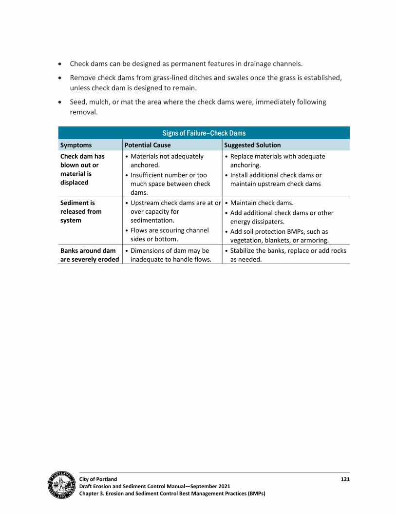
City of Portland 121 Draft Erosion and Sediment Control Manual—September 2021 Chapter 3. Erosion and Sediment Control Best Management Practices (BMPs)
• Check dams can be designed as permanent features in drainage channels.
• Remove check dams from grass-lined ditches and swales once the grass is established, unless check dam is designed to remain.
• Seed, mulch, or mat the area where the check dams were, immediately following removal.
Signs of Failure–Check Dams Symptoms Potential Cause Suggested Solution Check dam has blown out or material is displaced
• Materials not adequately anchored.
• Insufficient number or too much space between check dams.
• Replace materials with adequate anchoring.
• Install additional check dams or maintain upstream check dams
Sediment is released from system
• Upstream check dams are at or over capacity for sedimentation.
• Flows are scouring channel sides or bottom.
• Maintain check dams. • Add additional check dams or other
energy dissipaters. • Add soil protection BMPs, such as
vegetation, blankets, or armoring. Banks around dam are severely eroded
• Dimensions of dam may be inadequate to handle flows.
• Stabilize the banks, replace or add rocks as needed.

City of Portland 122 Draft Erosion and Sediment Control Manual—September 2021 Chapter 3. Erosion and Sediment Control Best Management Practices (BMPs)
BMP 3.23: Pipe Slope Drains Detail 3.23-A: Pipe Slope Drain
Definition: Pipe slope drains are temporary conduits, usually of flexible piping, that are placed from the top to the bottom of the slope to contain and convey runoff.
Applicability:
• Where concentrated runoff must be conveyed down a slope or around a work area to prevent erosion.
• In conjunction with interceptor dikes or swales to convey stormwater from the entire drainage area above a slope to the base of the slope.
Advantages:
• Effective method of conveying water down steep slopes.
• Reduces or eliminates erosion.
• Easy installation and little maintenance.
Limitations:
• Area cleared for drain installation requires stabilization to prevent erosion occurring under the pipe.
• Outfall systems constructed of pipe segments, which are banded and/or gasketed together, could develop leaks causing erosion and failure of the system. Failures on erodible or steep slopes can cause downstream sedimentation or even mudflows.
• The velocity of outflows from the pipe may be high and require additional scour prevention BMPs at the outlet.
May Not Be Used:
• Over natural channel features (unless authorized/permitted).
• On slopes less than 5 percent.
Most Effective When Used With:
• Armoring
• Diversion dikes and swales.
☐ General Controls
☐ Site Entry Controls
☒ Erosion Prevention
☐ Sediment Controls
☐ Site Stabilization

City of Portland 123 Draft Erosion and Sediment Control Manual—September 2021 Chapter 3. Erosion and Sediment Control Best Management Practices (BMPs)
Purpose: To carry concentrated runoff down slopes without causing erosion or saturation by preventing contact between bare slope soils and runoff.
• Planning Considerations - Proper installation, pipe sizing, and entry flow control are key to the success of pipe
slope drains. Failure of this type of facility usually results in severe erosion.
• Design Specifications - The collection and conveyance system must be designed to handle site runoff
generated from a 10-year, 24-hour peak flow event. In general, minimum recommendations for pipe sizing are as specified in the table below.
- Pipe slope drains must be constructed from heavy-duty flexible materials such as nonperforated, corrugated plastic pipe or specifically designed flexible tubing.
- Pipe slope drains must be placed directly on the ground or buried under the surface. The inlet/entrance to the pipe must be a standard flared end section metal toe plate or approved equivalent. This plate must be sized to fit flows and pipe opening (6 inches minimum). The slope of the pipe entrance must be at least 3 percent and oriented at an angle to collect flows.
- The soil around and under the pipe entrance must be thoroughly compacted to prevent undercutting, and geotextile fabric with 1-inch washed stone must be placed for velocity dissipation at the inlet of the pipe.
- A berm must be located around the inlet pipe to prevent bypass. In addition, exposed soils must be protected to prevent gully erosion from occurring beneath the pipe. If the pipe slope drain will be in place for more than 3 months, vegetation must be established around the inlet as soon as possible to protect the soils.
- The height of any dike, berm, or barrier must be at least 1 foot higher at all points than the top of the inlet pipe.
- All pipe sections must be watertight and anchored with hold-down grommets and/or stakes with cross-wire straps. Anchors must be placed at intervals not to exceed 10 feet.
- Pipe slope drains must discharge into an approved disposal facility. The area below the outlet must be stabilized with armoring (see BMP 3.8). Other stormwater flow and water quality control requirements and/or permits may be required for approved disposal, depending on project location.
- If the pipe slope drain is conveying sediment-laden water, BMPs must be used to trap the sediment in the runoff before the water is conveyed offsite.

City of Portland 124 Draft Erosion and Sediment Control Manual—September 2021 Chapter 3. Erosion and Sediment Control Best Management Practices (BMPs)
• Installation Tips - Ensure the flared inlet and outlet are keyed into the ground and secured so flows do
not bypass or pond at these locations. - Use a dike or swale along the top of the slope to direct flows to the pipe slope drain
inlet. - Use multiple drains for large slope areas. - Provide enhanced armoring at the bottom of all outlets (see BMP 3.8).
Maintenance Requirements:
• The inlet must be free of undercutting, and no water can go around the pipe inlet.
• Inspect inlet and outlet points daily, especially after any storm events. The inlet must be free of undercutting, and no water may go around the pipe inlet.
• If erosion problems exist anywhere along the slope drain, any holes, rills, or gullies must be filled with soil, compacted, and protected as necessary with appropriate materials such as erosion control blankets or rock.
• Any necessary maintenance and repair must be made prior to leaving the site, prior to inactivity at the site, and within 24 hours prior to periods when the site is anticipated to be inaccessible due to inclement weather.
• Perform maintenance on outlet structure and armoring to remove sediment build-up and fix any damage. Refer to BMP 3.8 for maintenance specifications for outlet armoring.
Removal Specifications:
• Remove temporary pipe slope drains only after slopes have been stabilized, a permanent collection and conveyance system has been established, and/or the conveyance of runoff down the slope is no longer needed.
• Live fascine slope drains can be used for permanent control BMPs. These drains are constructed from live cut fascines laid in trenches along the slope to convey water in lieu of a traditional pipe.

City of Portland 125 Draft Erosion and Sediment Control Manual—September 2021 Chapter 3. Erosion and Sediment Control Best Management Practices (BMPs)
Signs of Failure–Pipe Slope Drains Symptoms Potential Cause Suggested Solution Water is bypassing or undercutting the inlet
• Flared inlet is not keyed into the ground.
• No systems collect and convey water to the inlet.
• Inlet is undersized. • Inlet area is not compacted.
• Re-establish flared inlet into the flow path. • Add dikes or swales to redirect flow. • Recalculate the amount of expected flows
and upsize inlet and piping as necessary. • Re-compact the area around the inlet.
Pipe slope drain shifts on the slope
• Drain is not secured to the ground.
• Add additional strapping on sections of pipe.
• Increase the depth of stakes.

City of Portland 126 Draft Erosion and Sediment Control Manual—September 2021 Chapter 3. Erosion and Sediment Control Best Management Practices (BMPs)
BMP 3.24: Stormwater Runoff Barriers Detail 3.24-A: Stormwater Runoff Barriers #1 Detail 3.24-B: Stormwater Runoff Barriers #2
Definition: Stormwater runoff barriers are a group of portable materials, including triangular silt dikes, plastic dams, rock sack berms, and other materials, meant to impound stormwater and sediment laden flows. These systems are often manmade, can be modular and therefore replaced by sections, and may have sediment-settling capabilities. Some systems are also designed to dissipate flows.
Applicability:
• To prevent flows from leaving the site.
• For emergency flow diversion or flow blockage.
• Some products can be used to develop settling basins.
• Some products can act as inlet protection.
Advantages:
• Relatively simple installation and reusable.
• Can retain larger suspended soil particles.
Limitations:
• Can be easily damaged by construction equipment.
• Ineffective in steep swales, channels, or ditches or where water velocities or volumes are high.
May Not Be Used: Runoff barriers must not be used in streams and other drainage channels unless barriers are permitted for use to create a dry work area with flow channeled around the exterior.
Most Effective When Used With: Upstream erosion control practices.
☐ General Controls
☐ Site Entry Controls
☒ Erosion Prevention
☒ Sediment Controls
☐ Site Stabilization

City of Portland 127 Draft Erosion and Sediment Control Manual—September 2021 Chapter 3. Erosion and Sediment Control Best Management Practices (BMPs)
Purpose: To block or divert stormwater or erosional flows from entering or exiting a site; to provide temporary impoundment of stormwater or sediment-laden flows.
• Planning Considerations - Note that more permanent sediment control (ponds, traps) and flow diversion
structures (temporary swales) are preferred for long-term projects. Additional energy dissipators may be needed to control discharges.
- Prevent any diverted runoff from impacting right-of-way traffic. Do not redirect stormwater onto adjacent properties without permission.
• Design Specifications - Install manufactured products per manufacturer’s instructions. - For barriers with aprons, sink the first 4 inches of the apron on the
upslope/upstream side into a trench and backfill. - The maximum allowed length of slope before encountering a stormwater runoff
barrier is 100 feet. (Use the Revised Uniform Soil Loss Equation, Appendix C, for guidance.)
• Installation Tips - Organic materials can be incorporated as mulch after completion of site work if
approved by the City. Removal will necessitate a post-construction site visit. - Some barriers may be better suited for use on impervious surfaces.
Maintenance Requirements:
• Maintenance is critical.
• At no time must sediment be allowed to accumulate more than one third of the runoff barrier’s height.
• Sediment must be removed or re-graded into the slope, and new lines of barriers must be installed upstream of sediment-laden barriers.
• Check placement and performance often to avoid impacts from flows and/or vandalism.
• Check flow rates often, since high flows can limit performance and damage the barrier.
• Check that undercutting or end-flow is not occurring.
• Check that aprons are securely anchored.

City of Portland 128 Draft Erosion and Sediment Control Manual—September 2021 Chapter 3. Erosion and Sediment Control Best Management Practices (BMPs)
Signs of Failure–Stormwater Runoff Barriers Symptoms Potential Cause Suggested Solution Concentrated runoff or sediment flows are coming around or under BMP
• Insufficient materials. • Insufficient stake-down
during installation.
• Add additional material and align to contain flows.
• Reinstall with proper staking and inset.
Sediment is overwhelming the barrier
• Lack of upslope BMPs. • Inadequate
maintenance.
• Add erosion prevention or other sediment control BMPs.
• Clean sediment from behind bags or rolls.
City of Portland 129 Draft Erosion and Sediment Control Manual—September 2021 Chapter 3. Erosion and Sediment Control Best Management Practices (BMPs)
BMP 3.25: Sediment Traps and Ponds Detail 3.25-A: Sediment Trap Detail 3.25-B: Sediment Pond
Definition: Sediment traps and ponds are retention structures designed to remove sediment from runoff by holding a volume of water for a length of time and allowing particles to settle out.
Applicability:
• Downhill of areas with exposed soils.
• On larger sites or sites with stormwater infrastructure conveying runoff that needs to be detained or treated before work is completed.
Advantages: Can prevent sediment from leaving the site.
Limitations:
• Must be designed by a licensed engineer to meet specific site conditions.
• Sediment retention must be used as a final measure when included in an ESPCP and never used by itself.
• May be space intensive.
May Not Be Used: Alone without upslope clean stormwater diversion and erosion prevention BMPs.
Most Effective When Used With: Upslope diversion and erosion prevention BMPs such as mulch, fiber rolls/wattles, and rolled erosion control products.
☐ General Controls
☐ Site Entry Controls
☒ Erosion Prevention
☐ Sediment Controls
☐ Site Stabilization
City of Portland 130 Draft Erosion and Sediment Control Manual—September 2021 Chapter 3. Erosion and Sediment Control Best Management Practices (BMPs)
Purpose: To control sediment-laden flows leaving the site and to collect and store sediment eroded from exposed ground surfaces disturbed during site development.
• Planning Considerations - Designers are encouraged to consider whether ponds created to control sediment
and other pollutants during site development can also be used to manage post-development stormwater runoff. In general, erosion control ponds are larger than post-development stormwater management facilities. Stormwater management facilities must comply with the Portland Stormwater Management Manual.
- Because of site and soil variability, traps and ponds must be designed to meet specific site conditions. Given Portland’s climate and clay soils, most sediment traps and ponds when used alone will not meet instream and 1200-C permit discharge limits.
- Multiple traps or ponds may be needed to control sediments from leaving the site. - Designers are encouraged to use multi-cell or flocculant-based systems. - Temporary interceptor dikes or swales may be constructed to divert runoff to
sediment traps or ponds.
• Design Specifications - Facility size, configuration, and flow limits vary, based on volume of design runoff,
particle size and settling velocity of site soils. - In general, these facilities must be designed with adequate holding/residence time
(typ. 36 hours) to settle fine soils. - All water that has not come into contact with construction activities, such as
groundwater, must be diverted to prevent co-mingling with construction runoff. As such, facilities must not receive groundwater or other non-contact water. Construction-related groundwater dewatering requirements are described in the Portland SCM.
- Facilities must have stabilized inlet, outlet, and side slope structures capable of withstanding predicted flows before the facility receives flow.
- Depth markers must be installed within the sediment basin to easily measure sediment deposits after settling.
- The facility drainage system must dewater the pond from the surface of impounded waters to allow discharge of the cleanest water possible and allow sedimentation to occur. The drainage system must be designed such that the facility is dewatered within 36 hours following a rainfall event in order to, prevent overflow events, control vector breeding, and allow for maintenance.
- The facility must have adequate access for maintenance procedures and must be demarcated or otherwise flagged or fenced for protection from construction vehicles.

City of Portland 131 Draft Erosion and Sediment Control Manual—September 2021 Chapter 3. Erosion and Sediment Control Best Management Practices (BMPs)
- Sediment traps and ponds must be located: o Offline from any natural site drainage. o At the end of a site drainage control structure. o On the lowest portion of the site.
- Sediment Traps: o Sediment trap systems must be designed by a licensed Oregon Professional
Engineer. Each trap must have a tributary drainage area limited to 3 acres or less and slopes of less than 50 percent.
o The sediment trap may be formed by excavation or by construction of a compacted embankment. It must have a sediment storage depth not to exceed 1.5 feet, topped by a maximum 2-foot-deep settlement zone. Sediment trap side slopes must be 33 percent or flatter. The outlet of the trap must be a weir/spillway, providing a minimum 1-foot overflow depth between the spillway and embankment.
o Calculate the required sediment storage volume using the USDA Natural Resources Conservation Service’s Universal Soil Loss Equation or Revised Universal Soil Loss Program (as described in Appendix C of this Manual) and assume a minimum 1-year sediment accumulation period for design purposes. For the purposes of this calculation, assume that 1 cubic foot of sediment weighs 130 pounds.
o Determine the bottom surface area of the sediment trap using the calculated sediment volume and the maximum 1.5-foot depth and 33 percent side slope requirements.
o Determine the total trap dimensions by adding an additional 2 feet of depth for settling volume (before overtopping of spillway) above the sediment storage volume, while not exceeding 33 percent side slopes.
o Consider using additional freeboard within the spillway design to trap additional sediment.
o A 3:1 ratio of trap length to width is desirable. Length is defined as the average distance from the inlet to the outlet of the trap. Residence time will depend on soils and must be sufficient to allow for adequate settling.
- Sediment Ponds: o Pond systems must be designed by a licensed Oregon Professional Engineer. o A sediment pond may be formed by partial excavation and/or by construction of
a compacted embankment. It may have one or more inflow points carrying polluted runoff. Baffles must be included throughout the pond to spread the flow, which will increase the pond’s residence time.
o A securely anchored riser pipe is the recommended principal discharge mechanism, with an emergency overflow spillway. The riser pipe must be netted

City of Portland 132 Draft Erosion and Sediment Control Manual—September 2021 Chapter 3. Erosion and Sediment Control Best Management Practices (BMPs)
or hooded to prevent entry of large debris into the pipe. The riser pipe must also be perforated and covered with filter fabric and a gravel “cone” for filtration, or solid with a l-inch-diameter dewatering hole and perforated drain pipe.
o The sediment pond must have a sediment storage depth no greater than 3 feet, topped by a 2-foot deep (minimum) to 4-foot-deep (maximum) settlement zone and an additional 1-foot minimum of freeboard.
o The pond side slopes must be 33 percent or flatter and have temporary or permanent vegetative cover. Fencing of the facility may be required or desirable for safety around deep ponds without safety benches.
o Calculate the required sediment storage volume using the U.S. Department of Agriculture Natural Resources Conservation Service’s Universal Soil Loss Equation or Revised Universal Soil Loss Program (as described in Appendix C of this Manual) and assume a minimum 1-year sediment accumulation period for design purposes. For the purposes of this calculation, assume that 1 cubic foot of sediment weighs 130 pounds.
o The pond riser pipe and outlet pipe must be sized to carry at least the 10-year design storm equipped with velocity dissipation, or the designer must use a design storm acceptable to the City.
o A 3:1 ratio between the pond length and width is desirable. Length is defined as the average distance from the inlet to the outlet of the trap. Use baffles or forebays in the pond to help prevent short-circuiting and to increase the effective pond length where site conditions prohibit constructing a pond with a direct 3:1 length-to-width ratio.
- Inlets and Outlets: o All inlet and outlet structures must be adequately stabilized for predicted flows,
and stabilization be in place before flows are received. o Armoring or erosion control blankets rated to withstand predicted flows are
required. o Outlet protection must be provided to reduce erosion at the pipe outlet. A
turbidity curtain, fabric-wrapped outlet, or similar filter must be constructed to filter runoff before discharge from the construction site.
o Designers must designate survey control points to locate the riser during high water events.
o A floating skimmer or perforated riser with a gravel jacket, or their equivalent, and a retrieval rope and settling pad are required to further filter outlet discharge from the trap or pond.
o Pond and trap discharges must be at least 1 foot below the spillway. o Check Portland’s Stormwater Management Manual for more guidance on inlet
and outlet structures.

City of Portland 133 Draft Erosion and Sediment Control Manual—September 2021 Chapter 3. Erosion and Sediment Control Best Management Practices (BMPs)
• Installation Tips - Construct the trap or pond at the bottom of the drainage, sited on well-compacted
and stabilized soils. - Ensure that inlet and outlet structures are adequately designed for predicted flows. - Do not route all stormwater through the trap or pond. Segregate and divert clean
stormwater to an approved receiving system. - Stormwater management facilities must comply with the Portland Stormwater
Management Manual.
Maintenance Requirements:
• All ponds and traps must be maintained before major storm events to ensure they have capacity for flows. Designers must consider drain valves, forebays, and other features that provide ease of maintenance.
• Designers must consider the type of maintenance vehicle required and provide sufficient access. (Large equipment needs 15-foot-wide roads.)
Removal Specifications:
• Sediments must be removed when they fill one-third of the pond’s design capacity. A cleanout stake must be installed to indicate when maintenance is needed.
• Traps and ponds must remain in place until an adequate portion of the site is stabilized or adequately protected by other erosion prevention and sediment control BMPs. If the responsible party wishes to remove these facilities before complete site stabilization, the City will determine when and under what conditions these traps, and ponds may be removed.
Signs of Failure–Sediment Traps and Ponds Symptoms Potential Cause Suggested Solution Muddy water exits trap or pond
• Upstream erosion prevention controls are insufficient.
• Residence time is insufficient. • Outlet system does not
adequately filter flows.
• Provide additional erosion prevention BMPs.
• Recalculate sizing design and upsize facility if needed.
Trap or pond is overflowing
• Outlet is plugged. • Clean flows are running into
facility. • Facilities are inadequately sized.
• Maintain system. • Divert any clean stormwater flows
around worksite or facility to approved receiving system.
• Review sizing criteria and upsize facility if needed.

City of Portland 134 Draft Erosion and Sediment Control Manual—September 2021 Chapter 3. Erosion and Sediment Control Best Management Practices (BMPs)
BMP 3.26: Dewatering Definition: A method of removal and disposal of rising groundwater or rainwater from excavations and other collection areas. Additional dewatering requirements are described in the Portland Source Control Manual, Chapter 9.
Applicability:
• Public or private properties with foundation work excavations or graded areas where groundwater is present and infiltration cannot be achieved.
• Utilities infrastructure repair projects, including installation or repair of electrical conduits, vaults/tanks, sewer and storm drain systems, phone and cable lines, and gas or other fuel lines.
• Projects involving deep foundations, sites with contaminated soils, and footing excavations.
• Sites with contaminated soils.
Advantages:
• Depending upon the choice of filtration systems, can remove small particles of silt and clays.
• Can be used as an alternative to a sediment trap/basin on smaller sites.
• Can hold large amounts of sediment, reducing overall maintenance.
• Can be used in conjunction with other types of filters as a pre-filter.
• Can be easily mobilized from site to site.
• Can be used when infiltration cannot be achieved.
Limitations:
• Storage capacity is dependent upon the site.
• Limitations in removing silts and clays, depending upon selection.
• May require heavy equipment to load and unload system.
☐ General Controls
☐ Site Entry Controls
☐ Erosion Prevention
☒ Sediment Controls
☐ Site Stabilization

City of Portland 135 Draft Erosion and Sediment Control Manual—September 2021 Chapter 3. Erosion and Sediment Control Best Management Practices (BMPs)
• May be cost inhibitive.
• Discharge of construction-generated wastewater into a public sewer, public sump or body of surface water for a duration of 6 months or less. Plans to discharge wastewater for a duration exceeding 6 months will be required to undergo a more intensive application, review, and operations process.
• Requires City of Portland Bureau of Environmental Services authorization prior to discharge to an approved receiving system.
• Turbid discharge to the storm sewer and drainage system is prohibited.
• Sites with contaminated soils or groundwater may require additional considerations, as described in the Portland Source Control Manual.
May Not Be Used: Dewatering activities may not discharge into any waterbody.
Most Effective When Used With: N/A.
Purpose: To assess and appropriately dispose of rising groundwater or rainwater from excavations and other collection areas.
• Planning Considerations - Dewatering must comply with the Portland Source Control Manual, Chapter 9. - Requires submittal of Dewatering Plan and Dewatering Discharge Application form,
and approval from City of Portland Bureau of Environmental Services prior to discharge.
- Specific site controls and testing may be required to ensure that dewatering discharges do not impact local sewers and streams from increased flow volumes, flow velocities, or pollutant loads.
- Determine soil type prior to selecting dewatering system type and select an appropriate location that will maximize infiltration and reduce overall impacts.
- The selection of filter media must be based on desired performance and expected pollutants. Weir Tanks and Filter Boxes are effective for removal of large particles such as sand. Sand Media Filters are effective for removal of smaller particles such as sand and silt. Filter bags can remove large particles until fabric pores start to fill in or cake over then filter capacity increases to smaller sand and silt. Cartridge Filter Units will remove smaller particles such as silt and clay.
- Filter bags must be placed in a heavily vegetated area to increase their efficiency.

City of Portland 136 Draft Erosion and Sediment Control Manual—September 2021 Chapter 3. Erosion and Sediment Control Best Management Practices (BMPs)
• Design Specifications - Depending on season, flow rate, volume, or residential contamination:
o Design must comply with the City of Portland SCM. o Additional BMPs may be required to dissipate energy and minimize erosion
when discharging. o If offsite discharge is required, the City will assist the responsible party in the
selection of the appropriate receiving system as required by the City of Portland SCM. A permit or letter of authorization with discharge restrictions is required prior to discharge. Call BES Development Review 503-823-7122 for more information.
o Discharge may be allowed to the ground in a manner that ensures that no runoff leaves the site. This may require a permit or other authorization from the City and/or the State drainage authority.
o Discharge may be allowed to the storm sewer and drainage system, if the proposed discharge meets all applicable City code and administrative rule requirements, including discharge limits and flow rates. All discharges must meet the total suspended solids (TSS) and/or turbidity levels required by the City. Turbid and discolored discharge is prohibited. Additional requirements may apply to contaminated sites.
o Discharge may be allowed to the sanitary sewer, if the proposed discharge does not meet the applicable standards for discharge to the storm sewer and drainage system. Discharge of stormwater into the sanitary sewer system is not allowed unless prior approval is granted.
o Discharge may require treatment and flow limitations to protect City systems and to comply with City code and rule requirements.
o In some instances, it may be required to haul pumped groundwater or impounded stormwater offsite for treatment and disposal at an appropriate waste treatment facility.
- The site must be assessed for the issues listed below to help BES determine which discharge option to approve: o Assess water clarity: If the water is cloudy or turbid, there are dissolved and/or
settable solids in the water that must be filtered or settled out before discharge. o Determine if contaminants are present in impounded waters: Check for odors,
discoloration, or an oily sheen. Review the Phase I environmental assessment for the property to determine if contamination is likely. Check any soils and/or groundwater testing results. See the Portland SCM Chapters 8 and 9 for more information on determining if contaminants are present.
o If contamination may be or is present: See the Portland SCM for dewatering requirements at contaminated sites.

City of Portland 137 Draft Erosion and Sediment Control Manual—September 2021 Chapter 3. Erosion and Sediment Control Best Management Practices (BMPs)
- Sediments must be settled before discharge. All settling systems must be engineered and adequately sized for site conditions. In general, settling and filtering options include, but are not limited to: o Filtering through a sieve or other filter media (e.g., swimming pool filter). Simple
onsite filter systems can be constructed by wrapping the ends of the suction and discharge pipes with filter fabric; discharging through a series of drums filled with successively finer gravel and sand; and other filtering techniques such as those described in the Storm Drain Inlet Protection section.
o Manufactured bags or other systems. These systems do not always work on fine clay soils and will be allowed for use only where approved.
o Application of a polymer/flocculant where its use has been approved. o Filtered material must either be dried and reused onsite in a mixture with other
site soils or appropriately disposed of, based on the nature and levels of any contaminants present.
Maintenance Requirements:
• Inspect filtering devices frequently to make sure they are unclogged and operating correctly. Adjustments may be needed, depending on the amount of sediment in the water being pumped.
• Ongoing inspection is required in order to detect any malfunctions or operation of equipment.
• Discharge areas must be inspected periodically.
• Remove sediment when it reaches 1/3 capacity of a sediment barrier or as required by the manufacturer.
• Material must be placed in an approved location on site or exported from site.
Removal Specifications: Systems must be filled in or otherwise removed when permanent dewatering controls are in place and connected to a BES approved treatment and receiving system.

City of Portland 138 Draft Erosion and Sediment Control Manual—September 2021 Chapter 3. Erosion and Sediment Control Best Management Practices (BMPs)
BMP 3.27: Permanent Vegetative Stabilization Definition: A uniform perennial coverage of a site not covered by permanent structures, paving, or non-vegetative cover practices. All site soils are to be covered and stabilized with a mixture of permanent vegetative and non-vegetative cover prior to final approval unless otherwise exempted by Title 10.
Applicability:
• Exposed ground surfaces at the end of the construction period. Permanent cover must be established before the removal of any erosion control BMPs.
• Note: establishment of vegetation means that the seed has germinated and matured into a full stand., or planted vegetation such as live stakes or container plants have successfully established.
Advantages:
• Eliminates splash erosion, traps sediment, promotes infiltration, reduces runoff velocities, and controls dust.
• Can aesthetically improve site.
Limitations: Needs sufficient time for seed to establish.
May Not Be Used:
• On active stockpiles.
• By itself (without matting or compost blankets) between October 1 and April 30.
Most Effective When Used With:
• Soil testing, soil decompaction, surface roughening, and soil amendments.
• Seed cover (such as compost, straw mulch, peat, etc.).
• Bioengineering techniques.
• Stabilization and construction sequencing plan.
• Landscaping plan.
☐ General Controls
☐ Site Entry Controls
☐ Erosion Prevention
☐ Sediment Controls
☒ Site Stabilization

City of Portland 139 Draft Erosion and Sediment Control Manual—September 2021 Chapter 3. Erosion and Sediment Control Best Management Practices (BMPs)
Purpose:
• Establishing vegetative cover on disturbed soils provides long-term erosion protection, both above ground by providing splash control and within the soil by providing root systems that act as a binding structure to hold soils in place and control moisture content. Equally important, vegetation helps re-establish the ecological and biological function of soils after the degradation that occurs during development activity.
• Established vegetative cover also has benefits beyond erosion and sediment control, such as positive impacts on urban air quality and carbon dioxide absorption.
• Planning Considerations - Contractors will need to plan ahead to ensure that stabilization is established by
relevant deadlines. - If appropriate species are selected, grasses used for temporary cover can also be
part of the permanent site vegetation. The Portland Plant List, linked in Planning Considerations below, is a valuable reference for this BMP. Also refer to BMP 3.4: Temporary Vegetative Cover for a list of approved grasses and other groundcover plants for permanent vegetative stabilization.
- Although perennial ryegrass and non-native clover species are often used for erosion control, these plants can invade and cause problems for the City’s natural areas. Native grasses and other native plants are highly recommended for erosion control. Check the seed mixes listed in this chapter and refer to the Portland Plant List4 for information on native and nuisance plants. The Portland Plant List can be found at: https://www.portlandoregon.gov/citycode/article/322280.
- One seed mix/plant characteristic that should be considered is the predominant growth season. Grass species are often characterized as either warm or cool season grasses. To optimize establishment, a cool or warm season grass, or both, may be used, depending on whether the seed is intended to be planted in the spring or fall.
• Design Specifications - Preparation
o Topsoil must be prepared according to landscape plans, if available, or recommendations of the grass seed supplier.
o All vegetation sites require some surface roughening: stair-stepping, grooving, furrowing, or tracking.
4 https://www.portlandoregon.gov/citycode/article/322280

City of Portland 140 Draft Erosion and Sediment Control Manual—September 2021 Chapter 3. Erosion and Sediment Control Best Management Practices (BMPs)
- Seed o The use of native grass mixes is recommended. Check the seed mixes listed in
this chapter and refer to the Portland Plant List5 for information on native and nuisance plants.
o Seeding rates are based on a minimum acceptable Pure Live Seed (PLS) rate of 80 percent. When the PLS is below 80 percent, seeding rates must be adjusted accordingly.
o When possible, seed supplies must be selected from local sources that grow local genetic strains. These supplies will usually contain fewer weed species that could be noxious or invasive to the local environment.
o Seed may be applied by three different methods: Broadcast: Seed is scattered on the soil surface by hand or machine. This
method is used mostly for smaller areas. Hydroseeded: A mixture of water, seed, and sometimes fertilizers or mulch
that is sprayed onto exposed soils. This method is best for sites over 5,000 sq. ft. in size. (See BMP 3.10–Hydroseeding.)
Drilled: Seed is tamped down by equipment to inject seeds into exposed soils. This method is best for sites larger than 2 acres.
- Fertilization o Fertilize for grass seed only as needed or as specified in the supplier’s
recommendations. Compost is a superior soil amendment. o If fertilizer is necessary, slow-release fertilizers are more efficient and have fewer
environmental impacts. o Development areas within 50 feet of water bodies and wetlands must use a non-
phosphorus fertilizer. o Nitrogen fertilizer is not recommended for grasses. o Composted or straw mulch must be spread uniformly immediately following
seeding. - Mulch Used with Seed
o Composted or straw mulch must be applied at double the hydroseed application requirement (4,000 lbs./ac).
o Composted or straw mulch must be anchored on steeper slopes (greater than 33 percent) by working it in by hand or with equipment (rollers, cleat tracks, etc.).
5 https://www.portlandoregon.gov/citycode/article/322280

City of Portland 141 Draft Erosion and Sediment Control Manual—September 2021 Chapter 3. Erosion and Sediment Control Best Management Practices (BMPs)
o Hydromulch must be applied with grass seed at a rate of 2,000 lbs./ac or as specified by the supplier.
o On slopes steeper than 10 percent, hydroseed and mulch must be applied with a bonding agent (tackifier). The application rate and methodology must be in accordance with seed supplier recommendations.
o Netting and anchors must be used as needed. For disturbed areas on slopes and in ditches/swales, erosion control blankets, biodegradable netting, or jute may be used instead of bonding agents to provide a stable area for seeding. Netting must be anchored in accordance with the manufacturer’s recommendations.
- Sod o Sod may be used as a form of permanent vegetative stabilization that can
provide immediate, effective erosion protection. However, it has certain disadvantages, including expense, seasonal availability, potential difficulties with irrigation and root establishment, and maintenance difficulty on slopes greater than 33 percent.
o Sod may not be used in high-velocity channels/ditches and must be anchored and drained properly if installed in grassed waterways.
o Use sod that is generally weed-free, has uniform thickness (approximately 1 inch), and has a dense root mat for mechanical strength.
o The following steps are generally recommended for sod installation: o Shape and smooth the surface to final grade in accordance with the approved
grading plan. o Fertilize as per supplier’s recommendations. Non-phosphorus fertilizer is
required near water bodies and wetlands. o Work lime and fertilizer into soil 1 to 2 inches deep and smooth the surface. Lay
sod strips perpendicular to the direction of runoff flow, beginning at the lowest area to be sodded. Wedge strips securely into place and square the ends of each strip to provide a close, tight fit. Stagger joints at least 12 inches.
o Staple sod onto slopes 33 percent or steeper. o Roll the sodded area and irrigate. o Inspect sod area frequently for soil moisture content and root establishment. o Inspect daily during active construction period when stormwater runoff
(including from snowmelt) is occurring. o Inspect once every 2 weeks during inactive periods greater than 7 calendar days.

City of Portland 142 Draft Erosion and Sediment Control Manual—September 2021 Chapter 3. Erosion and Sediment Control Best Management Practices (BMPs)
Maintenance Requirements:
• All plantings require water and nutritional support during the first 3 years of establishment. Removal of invasive species is recommended. The property owner is responsible for ongoing maintenance of any plantings used for permanent cover.
• Watering is required to ensure adequate moisture to establish grass. Water must be supplied as needed, especially in hot or dry weather or on geographically challenging and special sites. Water application rates must be controlled to provide adequate moisture without causing runoff.
• Areas that fail to establish grass cover adequate to prevent erosion must be reseeded as soon as such areas are identified, and all appropriate BMPs must be implemented to establish adequate cover.
• The type of weed control (mechanical, hand removal, biological, or chemical methods) must be specified. Chemical use must be a last resort. Chemicals must never be used within stormwater management facilities. The selected weed control regime must adequately protect the selected seed mix.
Signs of Failure–Permanent Vegetative Stabilization Symptoms Potential Cause Suggested Solution Dying grass • Lack of adequate water.
• Lack of soil nutrients. • Lack of air pores in soil (soil too
compacted).
• Provide temporary irrigation. • Top-dress with compost to hold moisture
and provide nutrients and heat for seeds.
Bare spots in vegetative cover
• Lack of seed contact with ground.
• Seeding rate too low.
• Rake, drill, or walk in seed to ensure good ground contact.
• Overseed bare areas and ensure adequate water and nutrients.
City of Portland 143 Draft Erosion and Sediment Control Manual—September 2021 Chapter 3. Erosion and Sediment Control Best Management Practices (BMPs)
BMP 3.28: Non-Vegetative Permanent Stabilization Definition: BMPs intended to provide permanent protection from erosive activity for areas such as highly trafficked roads and walkways, stormwater outfalls and streambanks, slide remediation areas where the engineering solution (rock buttress) prohibits establishment of vegetation, and clean rock with geotextile underlayment that is incorporated into site landscaping.
Applicability: Armoring and scour protection, permanent structures, and reinforced soil retaining systems.
Advantages: Provides site stabilization where sufficient vegetative BMPs are infeasible or not preferred.
Limitations:
• Installation is labor intensive and may be more expensive than vegetative stabilization methods.
• If not properly screened and washed, can contain fine material that can erode and/or create dust problems.
• If inadequately sized, material may be susceptible to erosion on sloped areas.
• Pore spaces fill with dirt and debris over time; may provide a growing medium for weeds.
• Use in drainageways or waterways may be prohibited and will likely require a variety of permits from state and federal natural resource protection agencies.
Most Effective When Used With:
• Prepared base and geotextile underlayment.
• Erosion control matting when used for pathways or for slope applications.
• Bioengineering and vegetation.
☐ General Controls
☐ Site Entry Controls
☐ Erosion Prevention
☐ Sediment Controls
☒ Site Stabilization

City of Portland 144 Draft Erosion and Sediment Control Manual—September 2021 Chapter 3. Erosion and Sediment Control Best Management Practices (BMPs)
Purpose: Non-vegetative permanent stabilization BMPs are intended to provide protection against erosion as a part of constructed hardscapes or softscapes. These BMPs typically include rip-rap, gabion baskets, paved and rocked walkways, geotextile fabrics, reinforced soil retaining systems, mulches, gravel, and general site hardscape.
• Planning Considerations - Use of these systems in drainageways and other waterways may be prohibited. - Permanent stabilization ensures denuded or exposed soils are covered and
stabilized. All site soils are to be stabilized with a mixture of permanent vegetative and non-vegetative cover prior to final approval unless otherwise exempted by Title 10.
- Bioengineering techniques are the preferred alternative in bank and waterway projects because of their ability to provide upland habitat for animals and instream habitat for salmonids.
- In sensitive areas, it may be preferable to retain larger setbacks from the stream to avoid the need to armor banks and allow for natural channel migration.
- Use of these systems within a waterway or drainage area will likely require a variety of permits from state and federal natural resource protection agencies (Oregon Department of Fish and Wildlife, Oregon Department of State Lands, USACE, National Marine Fisheries Service, etc.).
• Materials - Concrete paving. - Clean rock 3/4-inch fractured face, with less than 10 percent fines. - Geotextile underlayment. - Decomposed granite as a permanent erosion protection method that consists of a
layer of stabilized decomposed granite placed over an erodible surface. - Degradable mulches when maintained and replaced appropriately; examples include
straw mulch, compost, wood chips, or hydraulic mulch. - Gravel mulch composed of washed and screened coarse to very coarse gravel,
16 mm to 64 mm (0.6"-2.5"), similar to an AASHTO No. 3 coarse aggregate. - Rock slope protection consisting of large rock or rip-rap (4"- 24") to stabilize slopes
with a high erosion potential and those subject to scour along waterways. - Other hardscape materials.
Maintenance Requirements: All systems must be maintained as installed for the life of the BMP. System repair typically consists of additional anchoring or top-dressing with fill materials on an as-needed basis.
City of Portland 145 Draft Erosion and Sediment Control Manual—September 2021 Chapter 3. Erosion and Sediment Control Best Management Practices (BMPs)
BMP 3.29: Turbidity Curtain Detail 3.29-A: Turbidity Curtain–Plan View Detail 3.29-B: Turbidity Curtain–Connections Detail 3.29-C: Turbidity Curtain–Connections and Anchoring
Definition: Turbidity curtains are floating devices anchored to the watercourse bottom that are specifically designed to limit sediment impacts within a body of water.
Applicability:
• During projects with instream, bank, or upslope ground disturbance, dredging, or filling within a waterway.
• Installation in a flowing watercourse, lake, or other area of water impoundment or flow that has aquatic resources that need protection.
Advantages:
• Limits sediment impact within a body of water where other BMPs may not be adequate.
Limitations:
• Various state permits (e.g., Division of State Lands, Department of Environmental Quality) or federal permits (e.g., U.S. Army Corps of Engineers) may be needed for these installations.
• Turbidity curtains are designed and selected for specific flow conditions. For sites with flow velocities or currents greater than 5 feet per second, a qualified engineer and product manufacturer must approve of the use.
May Not Be Used: Turbidity curtains must not be installed across streams unless they are specifically engineered to withstand expected flows and approved by applicable agencies.
Most Effective When Used With: Proper sediment control practices upslope of the watercourse.
☐ General Controls
☐ Site Entry Controls
☐ Erosion Prevention
☒ Sediment Controls
☐ Site Stabilization

City of Portland 146 Draft Erosion and Sediment Control Manual—September 2021 Chapter 3. Erosion and Sediment Control Best Management Practices (BMPs)
Purpose: To provide sedimentation protection for instream, bank, or upslope ground disturbance, dredging, or filling within a waterway.
• Planning Considerations - Multiple concentric curtains, in some cases both top-down and bottom-up, may be
necessary to fully contain sediment during in-water work. - All cleaning operations must also use good sediment control practices. Consider
sizing materials adequately to allow maintenance to occur only before removal and not throughout the project.
• Design Specifications - Turbidity curtains must be installed parallel to the flow of the watercourse, allowing
for 10 to 20 percent variance in the straight-line measurements. Allow for at least 50 feet between joints in the curtain and no more than 100 feet between anchor or stake locations.
- Turbidity monitoring must be conducted to evaluate curtain effectiveness, and contingency BMPs must be implemented immediately if suspended sediment escapes in excess of allowable limits.
- Turbidity curtains must extend the entire depth of the watercourse. In significant wind, wave, or tidal action areas, a 10- to 12-foot depth is the most practical because of fabric and mooring anchor strain from the heavy water and sediment loads.
- For tidal situations or in areas heavily impacted by wind-generated wave action, turbidity curtains must have slack to follow the rise and fall of the water level without submerging. Curtains must also maintain adequate flow-through, usually by using heavier woven fabric for the bottom sections of the curtain.
- Materials must be of strong, heavyweight materials that have UV inhibitors. The tensile strength must be sufficient to withstand predicted flows. All material seams and line attachments must be sewn or vulcanized welded into place. Materials must be of bright colors, when applicable, to attract attention of boaters or swimmers using areas near the worksite. Flotation devices for turbidity curtains must be flexible, buoyant units contained in an individual flotation sleeve or collar attached to the curtain. Flotation devices must be secured to prevent shifting and ensure proper flotation along the entire length of the curtain.
- Turbidity curtains must be anchored by vinyl-sheathed steel cable at the top, with a breaking strength as per engineer specifications, but 10,000 pounds at the minimum. At the bottom, a load line with chain incorporated into the bottom hem of the curtain must be used for ballast to hold the curtain vertical.
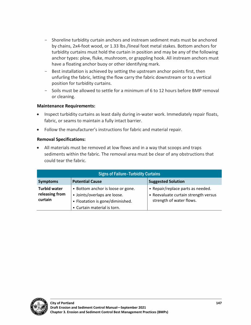
City of Portland 147 Draft Erosion and Sediment Control Manual—September 2021 Chapter 3. Erosion and Sediment Control Best Management Practices (BMPs)
- Shoreline turbidity curtain anchors and instream sediment mats must be anchored by chains, 2x4-foot wood, or 1.33 lbs./lineal foot metal stakes. Bottom anchors for turbidity curtains must hold the curtain in position and may be any of the following anchor types: plow, fluke, mushroom, or grappling hook. All instream anchors must have a floating anchor buoy or other identifying mark.
- Best installation is achieved by setting the upstream anchor points first, then unfurling the fabric, letting the flow carry the fabric downstream or to a vertical position for turbidity curtains.
- Soils must be allowed to settle for a minimum of 6 to 12 hours before BMP removal or cleaning.
Maintenance Requirements:
• Inspect turbidity curtains as least daily during in-water work. Immediately repair floats, fabric, or seams to maintain a fully intact barrier.
• Follow the manufacturer’s instructions for fabric and material repair.
Removal Specifications:
• All materials must be removed at low flows and in a way that scoops and traps sediments within the fabric. The removal area must be clear of any obstructions that could tear the fabric.
Signs of Failure–Turbidity Curtains Symptoms Potential Cause Suggested Solution Turbid water releasing from curtain
• Bottom anchor is loose or gone. • Joints/overlaps are loose. • Floatation is gone/diminished. • Curtain material is torn.
• Repair/replace parts as needed. • Reevaluate curtain strength versus
strength of water flows.
City of Portland 148 Erosion and Sediment Control Manual—September 2021 Chapter 3. Erosion and Sediment Control Best Management Practices (BMPs)
3.4. Instream Control Practices Instream erosion, sediment, and pollution control practices are commonly used during instream construction projects such as wetland grading, stream riparian projects, culverts and bridge crossings. Instream erosion, sediment, and pollution control BMPs are intended to ensure that habitat disturbance is kept to a minimum and that work activities are isolated from the receiving streams.
No work in flowing water must be performed. Work in and near the critical areas must be isolated from concentrated flow or streams flow. Once work in this area begins, priority must be given to the completion of the work and final stabilization of all disturbed areas. Planning and design considerations for erosion control associated with in-water work include, but are not limited to:
• Oregon Department of Fish & Wildlife In-Water Work Window
• Storm flow potential for other source systems contributing to the project drainage system and/or receiving waters.
• In-stream flow rates and seasonality of flows.
• Stream survey needs.
• Flood plain maps.
Projects that cross or otherwise work within the waterway must strive to limit the amount of work that occurs within the water flow line. General control BMPs that can reduce the amount of instream work include limited access from bank areas, diverting the stream around work areas, or project scheduling during period of time with no or limited flows.
Turbidity curtains (see BMP 3.29) can aid in sediment control during construction. Additional instream sediment control BMPs may include:
• Cofferdams
• Sediment/turbidity curtains
• Temporary stream crossings
• Gravity dispersion/bypass pumping
• Stream diversion channels
Instream construction projects almost always require approval from USACE, ODEQ, or other relevant agencies.

City of Portland 149 Draft Erosion and Sediment Control Manual—September 2021 Chapter 4. Pollution Control BMPs
Chapter 4. Pollution Control BMPs Pollution control BMPs are designed to prevent or reduce the discharge of pollutants to soil, stormwater, and impervious surfaces from site activities that support development or ground disturbance. In general, these practices focus on:
• Using erosion prevention and sediment control BMPs to keep construction site pollutants and other hazardous waste from washing off.
• Enclosing or covering material storage areas to prevent contact with stormwater runoff.
• Complying with hazardous waste and materials handling and disposal laws.
• These BMPs must be used for all projects where hazardous materials are to be used on the worksite. These BMPs strive to control raw materials, byproducts, finished products, containers, and material storage areas exposed to wind, rain, or runoff.
• All sites must ensure that workers know the rules and practices of the worksite and that there is a strong effort to enforce them. All locations for materials storage, hazardous materials use, or washing operations must be designated on the ESPCP (see Chapter 2). State and federal agencies may require additional pollution control BMPs.
4.1. Construction Site Pollutants Many development activities can generate other pollutants besides sediment.
Although sediment is the most prominent pollutant generated at a development site, several other wastes, byproducts, and construction site materials can be harmful to worker health, streets and stormwater conveyance systems, and streams or other waterways. Table 4-1 describes some of the most common site pollutants generated by development activity and some of the impacts of those pollutants. It also gives general guidance on what to do with the materials.
In general, good housekeeping practices are the main controls used for development-related activities. Work rules and practices are required to reinforce pollution prevention and discharge control to all workers at the job site. Worker education and training are essential.

City of Portland 150 Draft Erosion and Sediment Control Manual—September 2021 Chapter 4. Pollution Control BMPs
Table 4-1. Common Construction Site Pollutants Activity Waste Impacts Action
Demolition
Asbestos Human hazard.
• Get an ODEQ permit prior to removal. Assure that waste is disposed of at a landfill approved to take asbestos.
• Obtain BES authorization to discharge impounded stormwater or other construction related wastewater that contacted with asbestos-containing materials to the sanitary sewer system6.
• Do not allow discharge into storm sewer or drainage system.
Solid Waste
• Poor aesthetics. • Dust. • Tripping hazard. • Sewer system blockage. • Human hazard. • Reduces instream oxygen. • Impairs fish movement and feeding.
• Solid waste can degrade your site in the eyes of neighbors and potential buyers.
• Unsecured waste may be cause for a nuisance or site complaint. • Control wastes in a designated area or facility. • Recycle or reclaim as much material as possible. Usable materials may be
donated, resold, or reused elsewhere, reducing hauling and disposal costs Do not allow materials to leave the site.
Equipment Operations, Washing, Fueling, and Maintenance
Antifreeze • Reduces instream oxygen. • Impairs groundwater resources. • Toxic to pets and children.
• Recycle, if possible. If not, contact local sewerage agency for discharge limitations and approvals.
• DO NOT pour into storm sewer or drainage system or on ground.
• Gasoline • Hydraulic fluid • Oils (gear, lubricating,
or engine) • Brake fluid • Used oil • Other bulk liquids or
chemicals
• Flammability hazard for site and sewer workers.
• Can kill fish, impair feeding, or smother gravels.
• Reduces instream oxygen. • May be a hazardous waste.
• Minimize amount of fuels, oils, and other materials needed onsite. • For small, short-duration projects, consider fueling and maintaining
vehicles back at your company yard or other offsite controlled location at the end of the project.
• Store fuels or oils in designated and marked areas. Provide berms or protection from construction traffic.
• Provide adequate secondary containment, spill control structures, spill response materials, and staff training.
• Show all equipment fueling and maintenance sites on your ESPCP and add notes to plan defining proper procedures to follow in these locations.
• Recycle or reuse oil if possible. if not, complete a hazardous waste determination to determine appropriate level of disposal.
• DO NOT allow oily materials, cleaning products, or soaps to enter storm sewer and drainage system.
6 City of Portland Fact Sheet, Asbestos-related BMPs for construction impounded stormwater: https://www.portlandoregon.gov/bes/article/690250

City of Portland 151 Draft Erosion and Sediment Control Manual—September 2021 Chapter 4. Pollution Control BMPs
Activity Waste Impacts Action
Concrete Work
• Sawcutting • Concrete
washout/slurry • Concrete finishing
• Sewer system blockage. • Contributes to instream turbidity. • Reduces instream oxygen.
• Control wastes onsite in defined area. • Dispose of wastes as per manufacturer. • DO NOT allow wastes/curing materials to enter storm sewer and drainage
system. Sealants • Flammability hazard for site and
sewer workers. • May be a hazardous waste. • Reduces instream oxygen.
• Do not buy or mix more than needed. • Paint excess out on scraps, let dry and dispose as per manufacturer. • Any leftover materials must be disposed of at approved facility. • DO NOT allow wastes or curing materials to enter storm sewer and
drainage system. Additives and curing materials
• Flammability hazard for site and sewer workers.
• May be a hazardous waste. • (Same as gas/hydraulic fluid, above.)
• Do not buy or mix more than needed. • Paint excess out on scraps, let dry and dispose of in dumpster. • Any leftover materials must be disposed of at approved facility. • DO NOT allow wastes or curing materials to enter storm sewer and
drainage system. • Grouting operations • Masonry/mortar • Stucco
• Process water and excess material can contaminate runoff.
• Dust from dry materials is potential air quality hazard.
• Provide full containment of the mixing facility or equipment that includes impermeable ground cover, berms, water recovery and overflow relief, and any other containment BMPs needed to eliminate discharge of materials to the right-of-way, site soils, and any off-site areas.
• Discharging process water to any City of Portland sewer system or connected system from mixing operations will require a permit from BES.
• Provide dust suppression during mixing and adding dry components.
Framing and Roofing
Wood preservatives • Flammability or toxic hazard for site and sewer workers.
• Can kill fish. • Reduces instream oxygen. • Impairs ecosystem function.
• Consider using alternatives to wood–e.g., plastic or plastic mixed with wood–for areas exposed to the elements. If you must use wood, minimize heavily preserved or pressure treated lumber.
• Buy materials with preservatives already applied offsite. • Do not buy or mix more than needed. • Leftover materials must be disposed of at an approved facility (see
guidance for Demolition Waste, above). Resins • Flammability or toxic hazard for site
and sewer workers. • Reduces instream oxygen.
• Do not buy or mix more than needed. • Completely dry out all containers and dispose of in dumpster. • Any leftover liquid must be disposed of at approved facility.
Solid waste • (Same as Demolition Waste, above.) • See above. Vacuum or line gutters to collect shingle debris. • DO NOT rinse shingle debris down downspouts or offsite.

City of Portland 152 Draft Erosion and Sediment Control Manual—September 2021 Chapter 4. Pollution Control BMPs
Activity Waste Impacts Action
Plumbing HVAC
Solid waste • Metal debris can leach long-term harmful chemicals to streams.
• Poor aesthetics. • Dust. • Tripping hazard. • Sewer system blockage. • Reduces instream oxygen. • Impairs fish movement and feeding.
See above.
Solvents/ degreasers
• Flammability hazard for site and sewer workers.
• Reduces instream oxygen. • Impairs groundwater resources.
• Reuse and recycle when at all possible. • Contain materials on impervious surfaces. • DO NOT rinse materials to storm sewer system or onto the ground. Dispose
of materials through an approved recycling or disposal facility.
Painting
Paint thinner • Same as Solvents. • Same as Solvents. Let thinners settle and strain out materials to allow for reuse.
• Dispose of material only after it is too contaminated to reuse any more. • Dispose of materials per manufacturer recommendations. Do not discharge
to storm sewer or sanitary sewer. Paints • Flammability or toxic hazard for site
and sewer workers. • Reduces instream oxygen. • Harmful to aquatic systems.
• Reuse and recycle when at all possible. • Paint latex paint excess out on scraps, let dry and dispose of in dumpster.
Check with Fire Marshal for oil-based disposal. Leftover materials must be disposed of at approved facility.
• DO NOT rinse materials or equipment to storm sewer.

City of Portland 153 Draft Erosion and Sediment Control Manual—September 2021 Chapter 4. Pollution Control BMPs
Activity Waste Impacts Action
Landscaping
Fertilizer • Increases algae growth. • Reduces instream oxygen. • Affects pH balance.
• Design sites with native and other plants that need little or no additional soil amendments.
• Use composts or organic fertilizers instead of nitrogen- and phosphorus- based fertilizers when at all possible.
• Control fertilizer piles, providing protection from rain and runoff if needed. • Till all fertilizers well into the topsoil layer.
Pesticides/ herbicides
• May create health hazard for site and sewer workers.
• Can kill fish. • Harmful to aquatic systems. • Can impair groundwater resources.
• Design sites with native and other plants that need little or no horticultural chemical care.
• Use biological and structural controls before resulting to chemical controls. If chemical control is needed, consider using organic compounds.
• Do not mix more than is needed for the site. • Time application to specifically address pest or condition. • Do not use in areas with stormwater management facilities. See Portland
Stormwater Management Manual for guidance. • Watch overspray, especially over water.

City of Portland 154 Draft Erosion and Sediment Control Manual—September 2021 Chapter 4. Pollution Control BMPs
4.2. Trash and Debris Containment and Disposal Trash and debris can pose an additional hazard to streets and stormwater conveyance systems and to the health of waterways. Designated waste collection areas and containers must be provided to reduce or prevent the discharge of windblown and floatable pollutants from construction or landscaping activities. The following practices must be employed to contain trash and debris:
• Evaluate waste likely to be generated at the site. Determine which wastes will warrant stricter controls because of their hazardous nature and which wastes are reusable or recyclable.
• Consider buying some materials in bulk or in alternative, reusable containers to cut down on packaging wastes.
• Select designated waste collection areas onsite. Collection areas may be specific to each part of the operation–e.g., a metal recycling area to contain HVAC, plumbing, or framing metal wastes. Where possible, avoid siting waste areas in the street or adjacent to other properties; there may be street permit or building code issues. Consider locating these receptacles adjacent to or within the site’s rock entry access to allow for storage on a compacted base and easy removal of wastes.
• Provide an adequate number of containers with lids or covers that can be placed over the containers to keep rain out or to prevent loss of wastes when it is windy. Make sure that dumpsters are used only for wastes approved for disposal in construction or municipal landfills. All hazardous or special wastes must be segregated from standard trash and construction debris.
• Provide a waste receptacle for food-related trash and wastes.
All building projects in Portland with a permit value of $50,000 or more (including construction and demolition phases) are required to separate and recycle certain materials from the job site. The general contractor is responsible for ensuring recycling at the job site, including recycling by subcontractors, and for completing a Pre-Construction Recycling Plan Form. Contact the City’s Office of Sustainable Development at 503-823-7222 for more information.

City of Portland 155 Draft Erosion and Sediment Control Manual—September 2021 Chapter 4. Pollution Control BMPs
4.3. Hazardous Waste As noted in Table 4-1 above, some construction pollutants may require additional BMPs to comply with hazardous waste and materials handling and disposal laws. See City of Portland Construction Specs 2020, Section 00291.00.
In general, the following materials may require additional controls and/or consideration during use and disposal:
1. Oil/water-based paints
2. Form oil and used oils
3. Sealers
4. Degreasers
5. Petroleum products
6. Vehicle batteries
7. Pesticides and herbicides
8. Fluorescent and high-density lamps
9. PCBs (polychlorinated biphenyls–found in old electrical equipment)
10. Asbestos (in insulation, tiles, joint cements and caulks, stucco, and a variety of materials)
11. Lead (in paints, roofs, tank linings, plumbing soft solder)
12. Contaminated soils
All contractors are encouraged to visit ODEQ hazardous materials program7 for more information about regulations that may be relevant to their development site.
7 https://www.oregon.gov/deq/Hazards-and-Cleanup/hw/Pages/default.aspx

City of Portland 156 Draft Erosion and Sediment Control Manual—September 2021 Chapter 4. References and Citations
Chapter 5. References and Citations California Association of Stormwater Quality Agencies (CASQUA). California Stormwater
BMP Handbook, EC-16 Non-Vegetated Stabilization: Microsoft Word-EC-16 Non-vegetated Stabilization_Rev0.doc (stancounty.com)
Erosion Control Technology Council. Rolled Erosion Control Product types: https://www.ectc.org/rolled-erosion-control-products-recps-
Minnesota Stormwater Manual. Sediment control practices-Check dams: https://stormwater.pca.state.mn.us/index.php/Sediment_control_practices_-_Check_dams_(ditch_checks,_ditch_dikes)
Natural Resource Conservation Service (NRCS). Engineering Field Handbook Chapter 18: Soil Bioengineering for Upland Slope Protection and Erosion Reduction: https://directives.sc.egov.usda.gov/OpenNonWebContent.aspx?content=17555.wba
Natural Resource Conservation Service (NRCS). Urban Soil Primer: https://www.nrcs.usda.gov/Internet/FSE_DOCUMENTS/nrcs142p2_052835.pdf
North Carolina State Extension Publications. Mulch Options for Erosion Control on Construction Sites. https://content.ces.ncsu.edu/mulch-options-for-erosion-control-on-construction-sites
Oregon Department of Environmental Quality (ODEQ). 1200-C Construction NPDES Permit Application: wqp1200cInfo.pdf (oregon.gov)
Oregon Department of Environmental Quality (ODEQ). Hazardous Material Program: https://www.oregon.gov/deq/Hazards-and-Cleanup/hw/Pages/default.aspx
Portland Bureau of Environmental Services (BES). Asbestos-related BMPs for construction impounded stormwater: https://www.portlandoregon.gov/bes/article/690250
Portland Bureau of Environmental Services (BES). Portland Plant List: https://www.portlandoregon.gov/citycode/article/322280
U.S. Department of Agriculture (USDA). Forest Service Erosion Control Treatment Selection Guide: https://www.fs.fed.us/t-d/pubs/pdf/hi_res/06771203hi.pdf