Embed Size (px)
Citation preview

Page 1 of 31 Effective from 01.01.2015 RDSO/SPN/TC/102-2013 Version 1.0
DRAFT SPECIFICATION
OF
SMPS BASED TELECOM INTEGRATED POWER SUPPLY SYSTEM
FOR
STATION
VERSION 1.0
Number of Pages :31
SPECIFICATION NO. RDSO/SPN/TC/102-2013
TELECOM DIRECTORATE
RESEARCH, DESIGNS & STANDARDS ORGANISATION
LUCKNOW - 226011

Page 2 of 31 Effective from 01.01.2015 RDSO/SPN/TC/102-2013 Version 1.0
DOCUMENT DATA SHEET
Specification Number
RDSO/SPN/TC/ 102 -2013
Version
1.0
Title of Document
SMPS based Telecom Integrated Power Supply System for Station(TIPSS)
Prepared by:
Shri Rakesh Sahariya
Designation: Deputy Director/Tele-I
Shri Rajesh kumar Pandey
Designation: Director / Telecom-IV
Approved by:
Name: Shri D.N.Tewari
Designation: Executive Director/Telecom, RDSO
Abstract
This document defines specification of SMPS based Telecom Integrated Power Supply System (TIPSS) for Station

Page 3 of 31 Effective from 01.01.2015 RDSO/SPN/TC/102-2013 Version 1.0
DOCUMENT CONTROL SHEET
Designation
Organization Function Level
ADE/Telecom-I RDSO Member Prepare
Director/Telecom
RDSO
Member
Prepare
ED/Telecom
RDSO
-
Approval
Page 4 of 31 Effective from 01.01.2015 RDSO/SPN/TC/102-2013 Version 1.0
TABLE OF CONTENTS
Para No. Item Page No.
Abbreviations used 5
1.0 Foreword 6
2.0 General Requirements 7-11
3.0 Electrical & mechanical Requirements 12-17
4.0 Requirements of DSCA 18-19
5.0 Requirements of DC-DC Converter 19-20
6.0 Requirements of MPPT Charger 20-21
7.0 Source Prioritization 21
8.0 Packing 21
9.0 Test and Requirements 21-23
10.0 Test Procedure 23-26
11.0 Information to be given by purchaser 27
Annexure-I Typical Block Diagram of 48V Telecom Integrated Power Supply System(TIPSS)
28
Annexure-II Schematic diagram of Surge and lightening protection 29
Annexure-III General Requirements for RFIS 30-31

Page 5 of 31 Effective from 01.01.2015 RDSO/SPN/TC/102-2013 Version 1.0
ABBREVIATIONS USED
Abbreviation Detail
AMF Panel Auto Mains Failure Panel
ASM Assistant Station Master
DSA Distribution Switching & Alarm Unit
DG Set Diesel Generator Set
DOD Depth of Discharge
EMI Electromagnetic Interference
FRBC Float Rectifier Cum Boost Charger
IPS Integrated Power Supply
IS/IEC Indian Standard/ International Electrotechnical Commission
LCD Liquid Crystal Diode
LED Light Emitting Diode
MTBF Mean Time Between Failure
MOV Metal Oxide Varistors
OEM Original Equipment Manufacturer
PF Power Factor
PWM Pulse Width Modulation
RE Railway Electrification
RFI Radio Frequency Interference
SMPS Switched Mode Power Supply
SPD Surge Protection Devices
VRLA Valve Regulated Lead Acid
MPPT Maximum Power Point Trecking

Page 6 of 31 Effective from 01.01.2015 RDSO/SPN/TC/102-2013 Version 1.0
GOVERNMENT OF INDIA
MINISTRY OF RAILWAYS
RESEARCH, DESIGNS & STANDARDS ORGANISATION (RDSO)
DRAFT SPECIFICATION OF
"SMPS BASED TELECOM INTEGRATED POWER SUPPLY SYSTEM (TIPSS) FOR STATION"
1.0 FOREWORD
1.1 This Specification Requirement of Switched Mode Power Supply (SMPS) Based "Telecom Integrated Power Supply System (TIPSS) for Station" has been prepared for the use of various Telecom equipment provided at station on Indian Railways. This System will consists of 48Volts (V) SMPS based Power Plant to provide 48V for Control Communication equipments , OFC equipment, Radio equipments, GSM-R equipment STM1/4 OFC Equipment, PD MUX etc. provided at station. The System will also provide galvanically isolated 24V, 12V, and 3-6V DC for other telecom applications with the help of DC-DC Converter.
1.2 SMPS Based Telecom Integrated Power Supply is intended to be used in Auto Float Rectifier-cum Float-charger (FR-FC) and/or Float Rectifier cum Boost Charger (FR-BC) mode as a regulated DC power source; DC-DC Converters are for various DC power supply requirements of Telecom equipment at Railway Stations. Some of the typical requirements of Telecom equipment at the station are shown in Annexure-I of this Specification.
SN Name of Equipment Working Voltage Required Current
1. 25W VHF Set 12V DC 2-3 Amp
2. VF Repeater 12V DC 0.5 Amp
3. Gate Telephone 12V DC 100mA- 500mA
4. Gate Telephone 24 V DC 200 mA-1Amp
5. Way Station Control Telephone 12V DC 100mA
6. Magneto Telephone 3-6 V DC 50mA
7. STM1/4 OFC Equipment 48V DC 3 Amp
8. PD MUX 48V DC 2 Amp
9. Router 12V DC 3 Amp
10. Switch 12V DC 2 Amp
1.3 This specification requires reference to following specifications:
IRS: S 88/2004 Low Maintenance Lead Acid Battery
IRS:S 93/96(A) Valve Regulated Lead Acid Sealed Maintenance Free Stationary Battery
IRS: S 63/07 PVC insulated underground unscreened cables for Railway signaling
RDSO/SPN/144/2006 Safety & reliability requirements of electronic signaling equipment.
IS:9000 Basic environmental testing procedure for electronic and electrical item

Page 7 of 31 Effective from 01.01.2015 RDSO/SPN/TC/102-2013 Version 1.0
IEC-61643 Surge Protective Devices connected to low-voltage power
distribution systems EN 55022 European Standard for Information Technology EquipmentMIL HBDK 217F Military hand book "Reliability Prediction of Electronic
Equipment" IEC 61312 Protection against Lightning Electromagnetic Impulse
1.4 Wherever, in this specification, any of the above mentioned specifications is referred by number only without mentioning the year of issue, the latest issue of that specification is implied
2.0 GENERAL REQUIREMENT
2.1 Telecom Integrated Power Supply System shall consist of : (i) A Distribution-Switching-Control- Alarm Arrangement (DSCA) (ii) Float Rectifier-Cum-chargers (FR-FCs) or Float Rectifier cum Boost Chargers (FR-BCs) (in
N+1 configuration in hot-standby and one module in cold standby) (iii) DC-DC converter (in N+1 configuration in hot-standby) for each circuit of different voltages (i.e.
24V, 12V, 3-6V etc.) as shown in Annexure- I (iv) 48V battery set (v) 48V MPPT Battery Charger (optional) (vi) Solar Panel (optional)
2.2 The Telecom Integrated Power Supply System shall be capable of meeting the load requirement (equipment and battery bank) for various telecom equipments. The system shall be expandable at rack level itself, using the basic modules of the same rating.
2.3 To cater for higher load requirements, same type of modules mounted in the same rack shall be capable of working in parallel load sharing arrangement.
2.4 The Telecom Integrated Power Supply System shall be suitable for operation from AC Mains, solar power supply or from a DG Set.
2.5 The Telecom Integrated Power Supply System shall work satisfactorily either with VRLA maintenance free Battery as per IRS;S93/96(A) or Low Maintenance Lead Acid Battery as per IRS;S88/2004 with latest amendment. Battery as per purchaser requirement will be integral part of system.
2.6 (i) In case purchaser decides to provide solar power as additional source of power supply as indicated in clause 11.0 (3), the TIPSS shall be supplied with MPPT Charger as per provisions of Clause 6.0 of this specification.
(ii) In case purchaser decides to procure Solar Panels along-with TIPSS, then purchaser shall indicate its requirement as mentioned in clause 11.0 (4). If Solar Panels are required to be procured from TIPSS manufacturer along-with TIPSS, then Rating and Number of Solar Panels shall be indicated in clause 11.0(5). under heading “Information to be given by purchaser”. The solar panels shall be along-with TIPSS shall be supplied with MPPT charger as per provisions of Clause 6.0 of this specification.
(iii) The Solar panel modules (panels as per IRS:S 84/92 with Latest Amendment shall be procured from RDSO approved source and supplied along-with suitable Bracket & Bracing along-with TIPSS. Actual requirement of number of Solar Panels & its capacity etc. shall be indicated by purchaser based on actual site requirement.
2.7 One panel consisting of status indications and critical alarms of TIPSS is to be provided in ASM’s room. The monitoring panel shall be of wall mounting type. TIPSS manufacturer shall supply suitable cable as per RDSO specification (preferably 12 core, 1.5 sq.mm signaling cable as per IRS: S 63/2007) for connecting TIPSS to Status Monitoring Panel in Station Master’s room (distance to be given by Railways at the time indenting).
2.8 There shall be an automatic arrangement for disconnecting the mains within 500 ms to the rack whenever the input voltage is beyond the specified operating limits with suitable alarm indication. The TIPSS shall resume normal working automatically when the input is restored within the working

Page 8 of 31 Effective from 01.01.2015 RDSO/SPN/TC/102-2013 Version 1.0
limits. A self storing type static switch should be provided at the input. It shall be capable to with-stand 400volts input continuously without any damage.
2.9 COMPONENTS
I. Semiconductor and other components used in the equipment shall be of industrial grade with operating temperature range -25oC to + 85oC.
II. Semi-conductor power devices and other Solid state components used in TIPSS shall not be operated at more than 50% of the rated maximum peak voltage and at not more than 50% of the rated maximum average current under any prevailing conditions. Manufacturer shall submit design details, components datasheet at the time of type approval.
III. The manufacturer shall declare the peak reverse voltage, current rating and working temperature of the rectifier element under ambient conditions, the number of elements used and the manner of their connection. The peak reverse voltage rating should not be less than two times the expected reverse voltage across the devices.
IV. The recommended list of major components and their makes given in Annexure-VI of RDSO/SPN/S/165/2012 shall be applicable for this specification also.
V. Printed Circuit Board
(a) Printed Circuit Board shall generally conform to relevant provisions of latest RDSO/SPN/144/2006 for safety & reliability requirement of Electronic signaling equipment.
(b) As per as possible, Surface Mount Device (SMD) shall be used in PCBs of the sub-systems.
2.10 CABLES & WIRING
a) All the cables and wires used for wiring and inter connections of modules shall conform to specification No. IRS: S 76-89/IS 694 of grading 1100V. Aluminum wires shall not be used. The gauge of wiring shall be such that the current density does not exceed 3 amperes/mm square.
b) The colour scheme employed for the rack wiring shall be as below:
I) AC line : Yellow II) AC neutral : Blue III) Earthing : Green
IV) DC positive : Red IV) DC negative : Black V) Control wiring : Grey
c) All connections shall be made through crimped eyelets and shall be numbered with PVC cable marker rings/ inkjet printing on cables corresponding to the numbers/letters shown in the schematic wiring diagram. Soldering shall be used only where use of crimped eyelets is not possible.
d) All non-current carrying metal parts shall be bonded together and adequately earthed. e) All wiring shall be neatly secured in position by bunching /strapping & adequately supported.
Where wires pass through any part of metal panel or cover, the hole through which they pass shall be provided with rubber grommets.
f) There shall not be any exposed wiring outside the cabinet.
2.11 TRANSFORMERS AND CHOKES
Transformers and inductors/ chokes used shall be vacuum impregnated/ Vacuum Pressure Impregnated and shall be of natural air-cooled type conforming IS: 6297 (Category 3 & Grade 2). Class F or higher grade insulating material as per IS:1271 and polyester enameled copper winding wire conforming to IS 13730(Pt. 3) shall be used for winding transformers and inductors/chokes. The gauge of winding wires shall be such that the current density shall not exceed 2A/sq.mm. All exposed metal parts of the transformer including laminations shall be protected against corrosion.
2.12 FUSES & CONNECTORS a) All plug- in connectors shall be non-interchangeable. Connectors as per IEC 947 shall be
provided. b) Fuse holder identification shall include details of fuse rating and type. c) All power fuses shall confirm to specification IS 13703 / IS 9224.

Page 9 of 31 Effective from 01.01.2015 RDSO/SPN/TC/102-2013 Version 1.0
2.13 EARTHING
2.13.1 All non-current carrying metal parts and +ve of 48 V shall be bonded together and earthed. An earth terminal suitable for taking minimum 4 mm dia wire and with suitable marking shall be provided.
2.13.2 The TIPSS and its individual modules shall have earth terminals and shall be properly earthed to the cabinet. User shall provide earthing arrangement having earth resistance less than 5 Ohm. The manufacturer of TIPSS shall clearly provide earthing guidelines/ arrangement required for satisfactory working of the system. It shall be jointly ensured by Zonal Railways and manufacturer of TIPSS that earthing has been provided as per system requirement at the time of installation and commissioning and pre-commissioning check-list in this regard shall be signed jointly.
2.14 TERMINATIONS
a. The AC input connection to the FRBC/FRFC module shall be by means of plug and socket arrangement as per specification No. UL 248 & DIN 41576.
b. The DC output connection should be taken through irreversible plug and socket having power pins with locking arrangement.
c. The output of each FRBC/FRFC in the Negative lead shall be taken through the HRC fuse of 1.5 times of rated capacity of FRBC/FRFC.
d. In all cases, the male connector shall be mounted in the FRBC/FRFC module and the female connector shall terminate the cable.
e. To prevent hazards or damaging conditions, all plug-in components shall be non-interchangeable.
f. All the connections between DSA unit and FRBC/FRFC shall be through proper rated cables only.
g. Circuit breakers at the input of each FRBC/FRFC shall be easily accessible and rated to 16A for FRBC/FRFC module.
h. Proper termination for AC at the input of the circuit breakers and its output to the FRBC.
2.15 LABELLING AND MARKING
a. Each electrical/solid state component should be possible to be located by the layout/circuit drawing. The wiring shall be clearly and permanently identified with a designation or a colour code, which corresponds to the equipment circuit diagram. Where non-standard colours are used, cable functions shall be clearly and permanently labelled at both ends.
b. A screen printed cabling / wiring diagram shall be placed on the inside of the front door or any other convenient place for ready reference of maintenance staff.
c. Screen-printed Do’s & Don’ts, adjustment procedures and operating instructions shall be provided at convenient place on front panel of the TIPSS cabinet. One laminated block diagram shall also be provided at convenient place inside the cabinet.
d. The layout of the components and wiring shall be such that all parts are easily accessible for inspection, repairs and replacement.
e. All markings shall be legible and durable. Where the marking is by use of labels, they shall be metallic or screen-printed. These shall be firmly struck and shall not be capable of being removed by hand easily. They shall be placed in the vicinity of the components to which they refer.
f. All cubicles belonging to one TIPSS shall be identified with a common serial number.
g. Each FRBC, DC-DC converter shall be marked with its name & rating on its front panel. The placement for particular module in respective rack shall be clearly marked with its application for the purpose of appropriate replacement.

Page 10 of 31 Effective from 01.01.2015 RDSO/SPN/TC/102-2013 Version 1.0
h. Every SMPS based TIPSS shall be provided with a rating plate fixed outside at a conspicuous
place in TIPSS cubicle. It shall be clearly and indelibly etched, engraved or screen printed and shall show the following minimum information:
I) Name and trade mark of the manufacturer
II) Specification No.
III) Nominal AC input voltage and frequency
IV) Serial number and year of manufacturing.
V) Version number as per RDSO/SPN/144/2006.
i. All input and output terminals shall be clearly identified by using proper name tags/labels.
2.16 BATTERY BANK
2.16.1 TIPSS shall be suitable for charging 48V battery bank of 200 AH in case of RE area /300AH in case of non-RE area Low Maintenance cells as per IRS:S 88/2004 or VRLA Maintenance free cells as per IRS:S 93/96(A). Battery bank is part of this specification and the same shall be supplied and commissioned along with TIPSS. If Railway requires higher capacity batteries it should be mentioned specifically in the Purchase Order.
2.16.2 Battery racks of MS for VRLA batteries or wooden/ FRP rack for low maintenance batteries, along with its accessories, shall also be supplied with battery bank.
2.16.3 OEM shall supply copper cable of suitable dia as per IS: 694 and grade 1100V for connecting TIPSS to Battery bank (distance to be given by Railways at the time of indenting) as given below –
a) For 200AH battery – 16 Sq.mm b) For 300AH battery – 25 sq.mm
2.17 MODULE REPLACEMENT TIME AND MTBF
2.17.1 The mean time to replace a faulty module of IPS shall be less than 30 minutes.
2.17.2 The DC fan provided at rack /module level should have MTBF better than 70,000 hours at 40o C. The fan shall be covered with grill to prevent dust ingress.
2.18 INSTALLATION & COMMISSIONING
Installation & commissioning of TIPSS shall be as per guidelines issued by Railway Board/ RDSO/Zonal Railway.
3.0 ELECTRICAL AND MECHANICAL REQUIREMENT OF FR-FC & FR-BC MODULES
3.1 MECHANICAL REQUIREMENT
3.1.1 The FRBC/FRFC Modules shall be provided with natural/forced cooling. The capacity of FRBC/FRFC module will be 25 Amp .
3.1.2 The FRBC/FRFC module shall be removable from the front of the rack only. All AC input, DC output and alarm/control /monitoring cables inter connecting the modules and racks shall be easily removable/replaceable.
3.1.3 (i)All the modules shall be housed in 19” rack. Cable entries will be from the top of the rack. In the rack Control panel, FRBC /FRFC Module, DC-DC Converter should be placed from top to bottom respectively. It shall be also possible to place all the DC-DC Converters in a separate wall mountable rack of suitable/9U size which may be installed in the ASM Room situated at a maximum distance of 200 Mtr.
(ii) Whenever the DC-DC converter rack is mounted separately, the SPD (class-C) shall be used at both the ends of 48V supply (as per Cl. 3.2.12.3 of this specification).

Page 11 of 31 Effective from 01.01.2015 RDSO/SPN/TC/102-2013 Version 1.0
(iii)TIPSS manufacturer shall supply suitable cable as per RDSO specification (preferably Two core
signaling cable of 16 mm2 as per IRS: 63-07 with latest amendment) for connecting TIPSS to separate DC-DC converter rack to be mounted in Station Master’s room (distance to be given by Railways at the time of indenting).
3.1.4 RACK CONFIGURATION-
I. The cabinet shall be within the overall dimensions of 2000-mm max. Height 750 mm. max. Depth and 750 mm max. Width. Cabinet will have min 10-mm thick anti-vibrating pad and 75 mm x 5-mm bottom channel .The rack structure and the module frame shall be made up of rigid framework of steel profiles. The front door, if used, shall be of hinged type. The rear panel shall be provided with proper ventilation arrangement. Fan shall be provided at rack level for forced cooling. The operation of such fan shall be continuous.
II. The size of DC-DC Converter/ alarms rack to be provided in the ASM room shall be of 9 U size. The mounting arrangement of installation in the ASM room shall be approved by In-charge at the time of installation.
III. The racks and module cabinets shall be of robust construction. They shall be housed in self-supporting cubicles made of cold rolled closed annealed mild steel sheet of thickness not less than 1.6mm. The rack shall be adequately ventilated. The ventilating opening shall be less than 3mm size for protection against entry of lizard’s etc. The rack shall conform to IP31 type of protection as specified in table 1 of specification no. IS 2147-1962.
IV. The racks and the modules shall be treated with zinc chromate primer followed by electrostatic epoxy powder coating paint finished, passivation shall be done through seven stage process/sand blasting. Small metal parts such as nuts, bolts and washers shall be chrome plated. All other metal parts of the rack shall be plated for protection against corrosion.
V. The racks and the module cabinets shall be free from sharp edges & sharp corners.
VI. Provision of doors are optional, the cabinet sides shall have 3mm louvers covered with wire mesh. However, if the doors are not provided, the sub system shall have proper enclosures so that any reptile/ insect shall not enter in the TIPSS cabinet. The magnetic latches/handle shall be provided on the doors.
VII. The racks and the modules shall be designed for easy maintenance and installation.
VIII. Facility shall be provided at the top of the rack to connect external AC power and lightning arrestors (if provided inside the rack). Where cables pass through metal panels, suitable rubber grommets shall be provided to protect cable from damage.
IX. The modules shall be of modular type. The module shall be easily mounted or removed from the front side of the rack. The module shall be designed to slide into the rack on a suitable mechanical arrangement. Suitable arrangement shall be made for pulling out each module separately. The associated AC input, DC output connection, control/alarm & interface cable connecting the module shall be disconnected/installed easily without causing any interruption/damage to supply & working module.
X. The input and output terminals shall be accessible only when the cover of the cubicle is removed. All the terminals shall be clearly, neatly and indelibly marked to correspond with the wiring diagram for easy identification.
XI. Input and output connections of SMR, DC-DC converter, MPPT Charger shall be made using plug & socket of adequate rating having power pins with locking arrangement. The male connector shall be mounted on the device and the female connector shall be terminated on the cable. Use of terminal blocks for input and output connections is not accepted.
XII. The finish of steel and panels shall conform to relevant IS specification. The colour scheme shall be as follows:
a) Rack & doors Pebble Grey RAL 7032
b) All TIPSS modules shall harmoniously match with rack colour

Page 12 of 31 Effective from 01.01.2015 RDSO/SPN/TC/102-2013 Version 1.0
3.2 ELECTRICAL REQUIREMENT
FR-FC & FR-BC MODULES shall be based on High Frequency Switch Mode Techniques using switching frequencies of 20Khz and above.
3.2.1 AC INPUT SUPPLY:
The Telecom Integrated Power Supply system using FR-FC or FR-BC shall operate from single phase AC input supply range from 150-275V with nominal input frequency of 50Hz which may vary from 48-52Hz.
3.2.2 DC OUTPUT CHARACTERISTICS
(I) Auto Float Mode
(a) The Float voltage of each rectifier module shall be continuously adjustable & pre- settable at any value in the range of 48V to 56V. The prescribed float voltage setting is 54V for VRLA battery.
(b) The DC output voltage shall be maintained within ±1% of the half load preset voltage in the range 25% load to full load when measured at the output terminals over the full specified input range.
(II) Auto Charge Mode:
In Auto Charge Mode FR-FC shall supply battery & equipment current till terminal voltage reaches set value, which is normally 2.3V/Cell (55.2V) & shall change over to constant voltage mode it shall remain in this mode till a changeover to float mode signal is received. If battery voltage falls upto 48V it will change to Auto Charge mode.
3.2.3 EFFICIENCY: The efficiency of the unit shall be as given below:-
(a) At nominal input, output and full rated load better than 85 %
(a) For other specified input, output conditions (load between 25% to 100%) better than 80 %
3.2.4 INPUT POWER FACTOR
The input power factor at nominal input, output voltage and load 75% to 100% shall be between 0.95 lagging and 0.98 leading but it shall remain between 0.90 lag and 0.90 lead in any other working condition and load between 25% to 100%
3.2.5 TOTAL VOLTAGE HARMONIC DISTORTION
The total line harmonic voltage distortion shall not be more than 10%.
3.2.6 TOTAL CURRENT HARMONIC DISTORTION
The total current harmonic distortion contributed by the unit at the input shall not exceed 10% for input voltage range 150-275 V for load 50% to 100% of the rated capacity. While input voltage harmonic Distortion is less than 5%.
3.2.7 CURRENT LIMITING (VOLTAGE DROOP)
(i) The current limiting (Voltage Droop) shall be provided for Float Charge operation. The Float/Charge current limiting shall be continuously adjustable between 50 to 100% of rated output current for output voltage range of 44.4V to 56Volts. For test purposes upper limit of 100% + 5% and lower limit of 50% -5% shall be acceptable.
(ii) The float and charge current limit adjustment shall be provided on the front panel of the rectifier module or through the DSCA controller.
(iii) The FR-FC modules shall be fully protected against short-circuits. It shall be ensured that short circuit does not lead to any fire hazard.
3.2.8 SOFT START FEATURE
(I) Slow start circuitry shall be employed such that FR-FC module input current and output voltage shall reach their nominal value within 10seconds.

Page 13 of 31 Effective from 01.01.2015 RDSO/SPN/TC/102-2013 Version 1.0
(II) The maximum instantaneous current during start up shall not exceed the peak value of the
rectifier input current at full load at the lowest input voltage.
3.2.9 VOLTAGE OVERSHOOT/UNDERSHOOT
Following requirements shall be achieved without a battery connected to the output of FR- FC module.
(a) The FRBC/FRFC modules shall be designed to minimize output voltage overshoot/undershoot such that when they are switched on the DC output voltage shall be limited to ±5% of the set voltage & return to their steady state within 20ms for any load of 25% to 100%.
(b) DC output voltage overshoot for a step change in AC mains shall not cause shut down of FR-FC module and the voltage overshoot shall be limited to ±5% of its set voltage and return to steady state within 20ms.
(c) The modules shall be designed such that a step load change of 25 to 100% shall not result in DC output voltage overshoot/undershoot of not more than 5% return to steady state value within 10ms without resulting the unit to trip.
3.2.10 ELECTRICAL NOISE
(I) The rectifier (FRBC/FRFC) modules shall be provided with suitable filter on the output side. A resistor shall be provided to discharge the capacitors after the rectifier modules have stopped operation and the output is isolated.
(II) The Psophometric Noise (e.m.f. weighted at 800Hz) with a battery of appropriate capacity connected across the output should be within 2mV while delivering the full rated load at nominal input of 230V. For test purposes, this shall be taken as equivalent to 4mV when the battery is not connected and other conditions remaining the same as per ITU-T Rec P53.
(III) The Peak to Peak Ripple: voltage at the output of the rectifier module on full load without battery connected shall not exceed 300mV at the switching Frequency measured by an Oscilloscope of 50/60 MHz band-width (typical)
3.2.11 PARALLEL OPERATION
FRBC/FRFC operating in parallel with one or more modules of similar type, make and rating, other output conditions remaining within specified limits. The current sharing shall be within ±10% of the average current per rectifier module and within individual capacity of each rectifier module in the system when loaded between 50 to 100% of its rated capacity for all other working conditions.
3.2.12 PROTECTION
3.2.12.1DC OVER VOLTAGE PROTECTION
Each rectifier module shall be fitted with an internal over-voltage protection circuit. In case output DC voltage exceeds-57V(In Auto Float Mode), the over voltage protection circuit shall operate & shut off the faulty module. A tolerance of ±0.25V is permitted in this case. Restoration of the module shall be through a reset switch/push button. Shutting-Off of faulty FRBC/FRFC module shall not affect the operation of other FR-FCs operating in the rack. Operation of over- voltage shut down shall be suitably indicated on the module and also extended to monitoring/control unit.
The circuit design shall ensure protection against the discharge of the battery through the FR- FC module in any case. The over voltage protection circuit failure shall not cause any safety hazard.
3.2.12.2 FUSE/CIRCUIT BREAKERS
Fuses or circuit breakers shall be provided for each FRBC/FRFC module as follows:
(a) Live AC Input line
(b) Negative DC output
(c) Against failure of Control sensing circuit.
All fuses/circuit breaker used shall be suitably fault rated.

Page 14 of 31 Effective from 01.01.2015 RDSO/SPN/TC/102-2013 Version 1.0
3.2.12.3 LIGHTNING PROTECTION
System shall have modular type I/class. B and Type II/Class C type surge protection in TT configuration of wiring. Both type I/Class B and Type II/Class C arrestors should be from the same manufacture and shall be mounted as per the specific installation recommendations of the manufacturer to achieve perfect coordination.
(a) STAGE 1 PROTECTION (at the entry point of input 230V AC supply in the power/ equipment room)
The Stage 1 protection shall consist of coordinated Class I/ B & II/ C type SPDs at the entry point of input 230V AC supply in Power /Equipment room in TT configuration in a separate wall mountable box. The Class I/B SPD shall be provided between Line to Neutral & Neutral to Earth. They shall be spark gap type voltage switching device and tested as per IEC 61643 with the following characteristics and features-
SN Parameters Limits Between Line & Neutral
Between Neutral & Earth
1 Nominal Voltage (U0) 230V 230V 2 Maximum continuous operating voltage
(Uc) 255V 255V
3 Lightning Impulse current 10/350s (Imp)
25KA 50KA
4 Response time (Tr) 100 ñs 100 ñs
5 Voltage protection level (Up) 2.5KV 2.5KV
6 Short circuit withstand and follow up current extinguishing capacity without back up fuse (Isc & Ifi)
3KA 100A
7 Temporary Over Voltage (UT) 334V min. for 05 secs.
1200V min. for 200ms
8 Operating temperature / RH - 25oC to +80oC/ 95%
- 25oC to +80oC/ 95%
9 Mounted on din rail din rail
10 Indication Mandatory Optional
11 Pluggability Optional Optional
12 Potential free contact for remote monitoring
Optional Optional
13 Encapsulation Encapsulated Encapsulated
14 Degree of protection IP20 IP20
15 Housing Fire retardant as per UL 94
Fire retardant as per UL 94
(b) The Class I/ B SPD will be followed by Class II/ C SPD adjacent to it and connected between Line & Neutral. The device shall be a single compact varistor of proper rating and in no case a number of varistors shall be provided in parallel. It shall be voltage clamping device, thermal disconnecting type and shall be tested as per IEC 61643 with the following characteristics and features-
SN Parameters Limits (between Line & neutral)
1 Nominal Voltage (U0) 230V

Page 15 of 31 Effective from 01.01.2015 RDSO/SPN/TC/102-2013 Version 1.0
2 Maximum continuous operating voltage (Uc) 300V 3 Nominal discharge current 8/20s (In) 10KA
4 Maximum discharge current 8/20s (Imax) 40KA
5 Response time (Tr) 25 ñs
6 Voltage protection level (Up) 1.5 KV
7 Operating temperature / RH - 25oC to +80oC/ 95%
8 Mounted on Din rail
10 Indication Mandatory
11 Pluggability Mandatory
12 Potential free contact for remote monitoring Mandatory
13 Degree of protection IP20
14 Housing Fire retardant as per UL 94
(c) Class I/B and class II/C SPDs of Stage I shall be so coordinated that the voltage protection level of the coordinated devices is 1.5 KV. As such, these devices shall be from the same manufacturer and necessary test certificate in this regard shall be submitted by the manufacturer/ supplier.
(d) STAGE 2 PROTECTIONS (AT THE OUTPUT SIDE OF 48 V)
The Stage 2 protection shall consist of Class II/ C type SPDs for ≥ 24V-60V DC supplies at the output side inside the rack of IPS. These shall be provided for External circuits. The Class II/C type SPD shall be a single compact varistor of proper rating and in no case a number of varistors shall be provided in parallel. It shall be voltage clamping device and thermal disconnecting type. They shall be tested as per IEC 61643 with the following characteristics and features-
SN Parameters Limits (between L1 & L2, L1 & E , L2 & E)
1 Nominal Voltage (U0) 24V-60V DC 2 Maximum continuous operating voltage (Uc) 100 (DC)3 Nominal discharge current 8/20s (In) 10KA
4 Maximum discharge current 8/20s (Imax) 40KA
5 Response time (Tr) 25 ñs
6 Voltage protection level (Up) 0.5 KV
7 Operating temperature / RH - 25oC to +80oC/ 95%
8 Mounted on Din rail
10 Indication Mandatory
11 Pluggability Mandatory
12 Potential free contact for remote monitoring Mandatory
13 Degree of protection IP20
14 Housing Fire retardant as per UL 94
3.2.12.4 Length of all cable connection from SPDs to earth/ equi-potential busbar shall be kept less than 0.5mtrs. For this, a sub earth equi-potential busbar shall be installed at approx. 20cm from the SPD box. The details of connection of SPDs for Stage 1, & 2 of a typical installation with TIPSS is enclosed as Annexure-II.
Page 16 of 31 Effective from 01.01.2015 RDSO/SPN/TC/102-2013 Version 1.0
3.2.12.5 Procurement documents along-with specification of SPD from manufacturer /supplier of Lightning & Surge protection devices should be made available by the TIPSS manufacturer to purchaser along-with supply of TIPSS if demanded by Purchaser. Copy of the same shall be submitted by TIPSS manufacturer to RDSO at the time of acceptance test of TIPSS system.
3.2.13 ALARMS AND INDICATING LAMPS
Visual indications/display such as LEDs, LCDs or a combination of both shall be provided on each FR-FC module to indicate.
Functional Indications:
A. Mains available
B. FRBC/FRFC on Auto Float
C. FRBC/FRFC on Auto charge
Alarm Indications
A. AC/DC Rectifier module Over Voltage, Under Voltage or Output Fail
B. FRBC/FRFC over Load (Voltage Droop)
C. Fan fail (due to any reason)
Functional indications shall be extended as status and alarm indications as “ FRBC/FRFC” Fail to Distribution-Switching-control and Alarm Arrangement.
3.2.14 RADIO FREQUENCY INTERFERENCE SUPPRESSION: The module shall be designed to minimize the level of electromagnetic interference (EMI), both conducted and radiated, detected in its vicinity and generated by Switch Mode Power conversion Equipment operating within the rack. The radiated & conducted noise shall be within the limits specified in International specification no. IEC CISPR 22 ‘A’. The firm shall submit certificate to this effect from accredited national/international test house at the time of type test. Limits and test methods are given in Annexure-III.
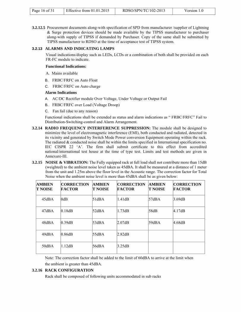
3.2.15 NOISE & VIBRATION: The Fully equipped rack at full load shall not contribute more than 15dB (weighted) to the ambient noise level taken as 45dBA. It shall be measured at a distance of 1 meter from the unit and 1.25m above the floor level in the Acoustic range. The correction factor for Total Noise when the ambient noise level is more than 45dBA shall be as given below:
Note: The correction factor shall be added to the limit of 60dBA to arrive at the limit when
the ambient is greater than 45dBA.
3.2.16 RACK CONFIGURATION
Rack shall be composed of following units accommodated in sub racks
AMBIENT NOISE
CORRECTION FACTOR
AMBIENT NOISE
CORRECTION FACTOR
AMBIENT NOISE
CORRECTION FACTOR
45dBA 0dB 51dBA 1.41dB 57dBA 3.69dB
47dBA 0.18dB 52dBA 1.73dB 58dB 4.17dB
48dBA 0.39dB 53dBA 2.07dB 59dBA 4.68dB
49dBA 0.86dB 55dBA 2.82dB
50dBA 1.12dB 56dBA 3.25dB

Page 17 of 31 Effective from 01.01.2015 RDSO/SPN/TC/102-2013 Version 1.0
a) Float Rectifier cum Float Charger (FR-FC) Modules or Float Rectifier Cum Boost Charger
(FR-BC) Modules, and DC-DC Converters. Separate wall mountable rack for DC-DC convertor as indicate in clause 11.0(7) under heading information to be given by Purchaser.
b) MPPT Charger modules in N+1 configuration with its Master Control.
c) Distribution-Switching-control-Alarm Arrangement (DSCA).
d) The number and rating of FR-FC, FR-BC and DC-DC Converters Modules shall be provided as per purchaser’s requirement. The Distribution-Switching-Control- Alarm Arrangement (DSCA) shall be provided for the Ultimate Expandable Capacity. All factory wirings for the rack shall be for the Ultimate Expandable Capacity so that only plugging-in of FR-FC or FR-BC module, DC-DC Converter shall in trance ultimate capacity of Telecom Integrated Power Supply System.
3.2.17 ADDITIONAL REQUIREMENTS FOR LMLA BATTERIES:
Low Maintenance Lead Acid batteries have special requirement of periodic boost charging @ 2.7V per cell. To meet this requirement, the Telecom Integrated Power Supply shall be so configured that in addition to the specification requirements, detailed above, shall also have a provision of a group of FR-BC (as per battery capacity) for charging the batteries @ 2.7V/cell. The current capacity may derated, while boost charging the battery set beyond 2.4 volt/cell
Float Rectifier-Float-Charger-Boost Charger (FR-FC): In addition to requirement of FR- FC Modules, the FR-FC Modules shall meet the following additional requirement.
a) The FR-FC module shall be programmable to work as FR-FC or FR-BC. When programmed as FR-FC, it shall be capable of working as FR-FC with other FR-FCs and shall comply with all the requirements of FR-FC. The rated capacity of the FR-BC when programmed as FR-FC shall be same as that of the other FR-FCs. The prescribed float voltage setting for conventional batteries is 52.8V.
b) It shall also be programmable as a Boost Charger (BC) under manual control after isolating it from the float bus.
c) As a Boost Charger, its output voltage shall be continuously adjustable and pre-settable at constant current up to 100% for voltage range 44.4 to 56V and up to 50% to 70% rated capacity at any value in the range of 56V to 64.8V as per design of the FR-BC. The firm has to specify the percentage of rated capacity of FR-BC module when it is working in the boost charging mode (56 to 64.8V)
d) The Boost Voltage shall be maintained with ±1% of the set value over the full boost current range as specified.
e) When programmed in Boost Charging Mode, FR-BC modules shall work in parallel load sharing arrangement with other FR-BC modules in the same mode, keeping other output conditions within specified limits.
(I) The current sharing shall be within ±10% of the average current per FR-BC module (in Boost charging Mode) in the system (mounted in the same or different racks) when loaded between 50 to 100% of its rated capacity (as BC) for all other working conditions.
(II) In addition to the Visual indications/display specified for FR-FC the following shall also be provided in FR-BC Module.
a. Functional Indications : FR-BC on Boost Mode
b. Alarm Indications : Following Alarms shall actuate in BC mode:
i) FR-BC Over Voltage.
ii) FR-BC Over Load (Voltage Droop)
f) PROTECTION: The module shall also be protected against DC over voltage in BC mode. Shutting-off of faulty FR-BC module in FR-BC mode shall not affect the operations of other FR-BC & FR-BC in FR-FC mode.

Page 18 of 31 Effective from 01.01.2015 RDSO/SPN/TC/102-2013 Version 1.0
4.0 REQUIREMENT OF DISTRIBUTION-SWITCHING-CONTROL AND ALARM
ARRANGEMENT (DSCA)GENERAL:
Depending on the system requirements system shall be provided with a Distribution- Switching-control-alarm Arrangement (DSCA) for the Ultimate Expandable Capacity.
The unit shall comprise of the following:
a) Termination for the batteries
b) Termination for the load
c) Interconnecting arrangement for power equipment
d) Battery Switching Arrangement (connection to/Isolation from system)
e) Termination for AC input to the rack
f) Termination for AC and DC to FR-FC modules
g) Circuit Breakers/Fuses etc.
Two numbers of potential free contacts for connecting to network monitoring system for monitoring DC output fail, DC output over voltage, DC output under voltage and mains fail shall be provided.
4.1 BATTERY HEALTH MONITORING
(a) Battery under voltage isolation: The system shall have provision for battery isolation using DC contactor. The battery isolation shall be effective at
i) 1.80V/cell (±0.012.V/cell) : For VRLA Battery ii) 1.85V/cell(±0.012V/cell) : For low maintenance lead acid battery iii) Battery under voltage adjustment shall be provided inside the switching control unit/DSA.
This setting shall be adjustable from 1.80 to 2.0V/cell. Battery shall get reconnected after restoration of mains.
(b) Battery Health Monitoring in Auto Mode: To keep the battery in healthy state, the battery condition shall be continuously monitored. On restoration of AC mains after an interruption, depending on the battery condition sensed, the system shall change over to Auto Boost Mode to charge the battery at higher voltage of 2.3/2.42V/cell for VRLA/Low Maintenance battery respectively till the battery is fully charged. It shall come back to auto float mode as per specified criteria.
(c) It should also be possible to monitor individual cell (for 24 Cells of 2 V each) of a battery bank. Status of all cells shall be made available in a display (provided in monitoring box itself) up to second decimal place. The strength of cells will be determined on the basis of cell voltage imbalance which will be settable. It should also be possible to provide status of week cell in ASM panel as specified in clause 4.2.There shall be provision to monitor the temperature of battery in case of VRLA battery.
(d) Battery Current Limiting Circuit: To ensure the availability of required load connected and safety of the battery in auto mode, the battery charging current limit shall be settable (5-15% of battery AH capacity) as per requirement.
(e) Temperature Compensation for VRLA Battery: There shall be provision for monitoring the temperature of battery and consequent arrangement for automatic temperature compensation of the FRBC output voltage to match the battery temperature dependent charge characteristics. Output voltage of the FRBC shall decrease or increase as per the type of the battery used by the purchaser. Failure of temperature compensation including sensor shall create an alarm and shall not lead to abnormal change in output voltage.
(f) Battery Reverse Polarity Protection: Protection for battery reverse polarity shall be provided in the system. The reverse polarity indication shall be provided near the battery terminal.
(g) DC Contactor: High quality DC contactors, UL approved should be used for battery path disconnection circuit.
4.2 REQUIREMENT OF ASM PANEL
Status monitoring panel shall be installed in the room of ASM on duty. The panel shall have following LED indications and alarms with resetting switch:

Page 19 of 31 Effective from 01.01.2015 RDSO/SPN/TC/102-2013 Version 1.0
Instruction Condition LED Indication
Remarks
A Run Generator Set
50% DOD RED Audio/ Visual alarm. Alarm can be acknowledged for audio cut off.
B Emergency start generator
60% DOD RED -do-
C System shut down
70% DOD RED All DC-DC converters to work. Audio alarm will continue till Generator is started.
D Call S&T staff Equipment fault RED Failure of any module or in case battery gets disconnected from circuit will give the alarm in panel. Alarm can be acknowledged for audio cut-off.
E Stop Gen Set FRBC changeover to float mode
GREEN Audio/ Visual alarm
Audio alarm in case of A, B & C shall be of one type of tone and there shall be different tone for the case of D & E cases.
4.2.1 In A, B & C conditions, the visual LED indication will remain lit until fault is cleared or the DG set is started and battery is charged upto 48V i.e. 2V/cell as the case may be until reset push button is pressed. In case of D condition, if fault is not cleared, the LED will continue to glow, even if reset push button is pressed.
5.0 REQUIREMENTS OF DC-DC CONVERTER
5.1 The DC/DC converter covered under this specification shall work satisfactorily meeting all the prescribed parameters as long as the DC input voltage is within 44V to 66V. The output regulation shall be ±1% of set value from 10% load to full load for the entire input range. Typical voltage ratings are 24V, 12V, and 3-6V DC and typical current ratings are 0.5 Amp, 1 Amp and 5 Amp depending upon load requirement.
5.2 Each converter shall be provided with a proper plug in arrangement for DC input & output. A toggle switch shall be provided for switching ON/OFF the unit.
5.3 The converter shall be provided with means for protection and visual indication on front panel for the following:
5.4 The unit shall be provided with over-load protection, over-voltage protection and output short circuit protection with fold back characteristics. The over-load protection shall be effective at 105% and output short circuit protection shall be effective at 110% of the rated current.
5.5 The DC over voltage protection shall be auto tracking type. Over voltage trip shall be set at approximately 110% of the set output voltage.
5.6 Output voltage settability of the converter shall be within the -2% of the minimum rated voltage and +2% of the maximum rated voltage of the converter.
5.7 Output shall be free from overshoot because of “Turn on /Turn off” or power failure or when the battery charger is switched ON/OFF.
5.8 In case of failure of DC-DC converter the output voltage shall not exceed beyond pre-set value. For this a Fail Safe Feature for the module be explained and demonstrated so as to , a) protect the Load
Description Nomenclature Indication
i) Input Power ON indication INPUT Amber
ii) DC-DC Converter output OK OUTPUT Green
iii) DC-DC Converter fail FAIL Red
Page 20 of 31 Effective from 01.01.2015 RDSO/SPN/TC/102-2013 Version 1.0
under all circumstances , b) maintain continuity of the DC circuit even if one of the module has failed (i.e.to isolate one module only and not the entire group ).
5.9 No load input current shall not be more than 10% of the rated input current at maximum full load for all setting of output voltage and input voltage variation from 44V to 58V ( 66V ) of nominal input voltage for DC-DC Converters of 50 VA and above.
5.10 Overall efficiency of the converter at full load shall not be less than 75% for converters rating from 50VA to less than 150VA at rated load and 80% for converters of 150VA or more rated output at 44V to 58V ( 66V ) of nominal input voltage. . For converters of rating 10VA - 50VA, overall efficiency shall be greater than 50%. The efficiency shall be measured at the maximum output voltage of the specified range.
5.11 Each DC-DC converters shall be of modular type which shall be fitted in main rack. The input and output connections shall be made using irreversible plug in connectors of appropriate rating.
5.12 Output must be isolated from input. Each DC-DC converter shall have blocking diodes at the output. The test points shall be provided before the blocking diode.
5.13 RADIO FREQUENCY INTERFERENCE SUPPRESSION: The DC-DC Converter shall be designed to minimize the level of Electromagnetic interference (EMI/RFI), both conducted & radiated in the vicinity of DC-DC Converter. The radiated & conducted noise shall be within the limits specified in International Specification No.EN-55022. The firm shall submit certificate to this effect.
5.14 The converter shall have self-resetting type protection from over load/ short circuit of DC output. The converters shall be adequately protected against surges/ lightning at the input.
5.15 The output ripple (peak to peak) of the converter shall not be more than 50mV at full load.
5.16 Provision shall be made for measuring voltage of DC-DC Converter modules with the help of common meter.
5.17 PARALLEL OPERATION:
DC-DC Converter operating in parallel with one or more modules of similar type, make and rating, other output conditions remaining within specified limits. The current sharing shall be within ±10% of the average current per converter module and within individual capacity of each converter module in the system when loaded between 50 to 100% of its rated capacity for all other working conditions.
6.0 REQUIREMENTS OF MPPT CHARGER (OPTIONAL)
MPPT( Maximum Power Point Tracking)Charger Module : The MPPT charger module shall be designed to take DC power form the SPV panels and convert it into suitable DC power so as to supply 48V DC bus demand. It should be used in N+1 configuration and should have following features:
(a) It should be using MPPT Algorithm. Efficiency at rated output voltage and full load should not be less than 93%. Even at less than full load, efficiency should not drop to less than 90% at 30% full load.
(b) It should work over higher DC ( SPV ) voltage and should cover 70V to 150V DC.
(c) Suitable DC filter with protection be provided at its output.
(d) It should have protection against Lightening and Surges at its input.
(e) It should have facility to be connected with the Mains ( AC ) based SMPS charger modules and should also work in stand-alone mode when AC mains is not available.
(f) It should work as priority over SMPS charger module so as to save the mains consumptions when PV is available
(g) It should have protection against DC overvoltage and should isolate itself in case of any such eventuality . It is Fail Safe feature of the module.
(h) It should have Auto Float/Boost Changeover , Battery path current limiting features.
(i) The module ratings should be 25A/Module.

Page 21 of 31 Effective from 01.01.2015 RDSO/SPN/TC/102-2013 Version 1.0
(j) Compliant to IEC 62509 with the exception of self consumption and set point accuracy (±3%
will be allowed).
(k) Protection against moisture and dust shall be of at least IP 31 level.
(l) Capable of handling 120% of module’s rated current.
(m) Temperature compensated charging.
(n) Provision of blocking diode, preferably a Schottky diode, to prevent the battery from discharging itself through the SPV system/ charge controller. The current capacity of the blocking diode shall be 50% higher than the short circuit current at STC. The peak inverse voltage (PIV) of the diode shall be at least equal to the open circuit battery voltage. In case any alternative to Schottky diode is proposed, then technical literature and evidence in support of successful working of the same should be submitted for the consideration of RDSO/ purchaser.
(o) On the SPV power source side, the charge controller shall be protected against lightning and surges with the help of SPDs if the distance between charge controller and AJB is more than 10 m. The SPDs used shall be rated for at least 10KA at 8/20 μSec for protection against lightning induced surges Class II as per IEC 61643-1. The voltage rating of the SPDs shall be at least 10V higher than the specified value of the SPV array.
(p) Protection shall also be provided against the following: battery overload, battery overcharge, short circuit and reverse polarity. Auto resettable reverse polarity protection should be provided.
(q) Cables of appropriate size shall be used to reduce the voltage drop between SPV and battery; and battery and the output of the charge controller.
(r) The charge controller shall incorporate the auto, bulk and float charging methods. Though not mandatory, manufacturers are however encouraged to provide equalization charging facility also. Battery charging modes shall be selectable as per battery type.
7.0 SOURCE PRIORITIZATION
If all power sources are available first priority will be given to solar energy. Power supply to DCDC converters, telecom loads and Battery will be supplied through solar modules. While solar energy is sufficient enough to support the load all other sources will be disconnected.
Second priority is to Grid supply.
Third priority is given to battery. When grid supply is not available, the main controller checks the healthiness of battery. If battery is at charged condition and state of charge is greater that 70%, battery power will be used to support DCDC converters, and telecom loads. If battery is also discharged and no other source is available, it will give an indication as well as potential free contact should be provided which may be utilized for starting the DG.
8.0 PACKING
8.1 Complete TIPSS shall be packed in suitable wooden boxes/crate, strong enough, without additional packing to prevent damage or loss to the unit during transit. Loose space inside the box/crate shall be filled up with suitable packing material.
8.2 FRBC module, DC-DC converters, shall be separately packed. These shall be wrapped in bubble sheet and then packed in thermocole boxes and empty space shall be filled with suitable filling material. All modules shall be finally packed in wooden case of sufficient strength so that it can withstand bumps and jerks encountered in a road / rail journey.
8.3 Each box shall be legibly marked at one end with code numbers, contents, quantity and name of manufacturer/ supplier. The upside shall be indicated with an arrow. Boxes should have standard signages to indicate the correct position and precaution "Handle with Care" with necessary instructions.
9.0 TEST AND REQUIREMENTS
Inspection & tests shall be carried out to ensure that requirements of this specification are complied. All tests, unless otherwise specified, shall be carried out at ambient atmospheric conditions on all the modules. For inspection of material, relevant clauses of IRS: S 23 and RDSO/SPN/144/2006 shall

Page 22 of 31 Effective from 01.01.2015 RDSO/SPN/TC/102-2013 Version 1.0
apply unless otherwise specified. Manufacturer shall provide necessary machinery and plants / /assistance for testing of the TIPSS.
9.1 INITIAL TYPE APPROVAL
Initial type Approval shall be given with solar option and without solar option. Typical system offered for Type Test shall be generally as per Annexure-I of this specification. In case any other configuration is proposed to be offered for Type Test, specific approval shall be taken by manufacturer from RDSO. Manufacturer shall furnish following information at the time of initial type approval of TIPSS system.
I) Details of protection provided and their effectiveness / proposed set values and range and working principle.
II) Bill of material for racks and modules. Details of semi conductors devices used and its specification and data sheets.
III) Safety margins in voltage, current, thermal (for junction temperature) along with the limit value for power devices, inductors and transformer etc.
IV) Installation & commissioning manual, Quality Assurance Plan and Service manual (consisting of indications and fault diagnostics, Do's & Dont's etc.)
V) Design approach for the TIPSS system and salient features through which required MTBF has been achieved.
While granting initial type approval, it shall be ensured that the system conforms to all the clauses and passes all type tests as mentioned in clause 9.3.1and other relevant guidelines of RDSO.
9.2 MAINTENANCE TYPE APPROVAL
DELETED
9.3 The following shall comprise the Type Tests:
i. Visual Inspection (Cl. 10.1)
ii. Insulation Resistance (Cl. 10.2)
iii. Applied high voltage test (Cl. 10.3)
iv. Temperature rise test (Cl. 10.4)
v. Performance test (Cl. 10.5)
vi. Test for protective devices (Cl. 10.6)
vii. Environmental & Climatic Test (Cl.10.7)
viii. Functional test (Cl. 10.8)
ix. Vibration test on modules as per RDSO/SPN/144/2006.
x. Static discharge test as per RDSO/SPN/144/2006. Electrostatic discharge test shall be carried out as per international standard IEC 61000-4-2 or its equivalent with 150 Pico Farad charged capacitor of 7KV and should be discharged through 330 ohm resistor.
Note:
(i) Test for protective devices and performance test shall be carried out before and after climatic test. There shall not be any significant deviations in the observations recorded.
(ii) Vibration & Static discharge test shall be conducted on one module of FRBC along with DSA unit, DC-DC Converter.
9.4 The following shall comprise the Acceptance test:
The acceptance test shall be carried out as per the sampling plan given in Clause in 9.4.1.
a) Visual Inspection (Cl. 10.1) b) Insulation Resistance (Cl.10.2)

Page 23 of 31 Effective from 01.01.2015 RDSO/SPN/TC/102-2013 Version 1.0
c) Applied high voltage test (Cl. 10.3) d) Temperature rise test (Cl. 10.4) e) Performance test (Cl. 10.5) f) Test for protective devices (Cl. 10.6) g) Functional test (Cl. 10.8)
9.4.1 Visual inspection shall be carried out on one of the TIPSS unit of each type. The functional test shall be carried on each TIPSS.The modules shall be tested for insulation resistance, high voltage test, temperature rise test, performance and protection tests as per the sampling plan given below:
Test Description Ins. Res.
HV test
Temp rise
Performance test
Protection test
SMPS (FRBC) N/2 N/2 N/2 N N
DC-DC Converter (of each type/ rating)
N/2 N/2 - N N
MPPT Charger - - - N -
Battery Bank –To be procured from RDSO approved source after RDSO inspection. In factory, the battery discharge test shall be simulated by a DC source for inspection purposes. 10 hrs discharge test for capacity: Sample shall be taken as per Clause 11.1 of IS: 8320-1982. Cells shall be taken from all banks of TIPSS at the time installation & commissioning of TIPSS .
N = Denotes the no. of modules offered for inspection. N/2 shall be rounded off to the next number. In case of any failure during acceptance test, the lot shall be rejected. For acceptance of the lot there shall be no failure in any of the test as mentioned under clause 9.4 above.
9.5 The following shall comprise the Routine test:
The routine test shall be carried out on every module of the TIPSS system and the results will be submitted by the manufacturer to the inspecting authority at the time of inspection.
a) Visual Inspection (Cl. 10.1) b) Insulation Resistance (Cl.10.2) c) Applied high voltage test (Cl.10.3) d) Performance test (Cl. 10.5) e) Test for protective devices (Cl. 10.6) f) Functional test (Cl. 10.8)
10.0 TEST PROCEDURE
10.1 VISUAL INSPECTION
Test for visual inspection shall be carried out as per relevant clauses of this specification and RDSO/SPN/144/2006.
10.2 INSULATION RESISTANCE
Insulation resistance (I.R) test shall be carried out:
1) before the high voltage test
2) after the high voltage test
3) after climatic test
The measurement shall be made at a potential of not less than 500 V DC. The insulation resistance shall be measured at module level / rack as follows:
i) Input line terminals and the body of the equipment

Page 24 of 31 Effective from 01.01.2015 RDSO/SPN/TC/102-2013 Version 1.0
ii) Output line terminals and the body of the equipment
iii) Input line terminals and output line terminals
iv) Between rack and earth
Value of the insulation resistance shall not be less than 10 M.ohm for the rack / equipment when measured at a temperature of 40ºC and relative humidity of 60%. There shall not be appreciable change in the values measured before and after high voltage test and after the temperature rise test.
After completion of climatic test, the values shall not be less than 5 M.ohm for the equipment when measured at a temperature of 40ºC and relative humidity of 60%.
Note: - In case, temperature and humidity prevalent at the time of the above measurements of insulation resistance are different from those specified above, the values of I.R. shall be obtained from the table given below –
R.H
25ºC 30ºC 35ºC 40ºC
60% 10 M.ohms 10 M.ohms 10 M.ohms 10 M.ohms
65% 10 M.ohms 9.0 M.ohms 8.5 M.ohms 8.0 M.ohms
70% 8 M.Ohms 7.0 M.ohms 6.5 M.ohms 6.0 M.ohms
75% 6 M.ohms 5.3 M.ohms 4.7 M.ohms 4.3 M.ohms
80% 4.2 M.ohms 3.6 M.ohms 3.3 M.ohms 3.0 M.ohms
85% 2.9 M.ohms 2.5 M.ohms 2.2 M.ohms 1.8 M.ohms
90% 2.0 M.ohms 1.6 M.ohms 1.3 M.ohms 1.0 M.ohms
95% 1.5 M.ohms 1.0 M.ohms 0.7 M.ohms 0.5 M.ohms
100% 1.0M.ohms 0.6 M.ohms 0.3 M.ohms 0.1 M.ohms
10.3 APPLIED HIGH VOLTAGE TEST
The module shall withstand the application of 2000 V AC rms for one minute without puncture and arching. The test voltage shall be approximately sine wave and of any frequency between 50 and 100 Hz. The high voltage shall be applied between the following:
(i) Input and earth
(ii) Output and earth
(iii) Input and output
NOTE:
For FRBC, item(ii) above shall be tested at 1000V AC rms
DC-DC Converter shall be tested for 1, 2 & 3 at 1000V AC rms.
The test shall be carried out after removing surge arrestors /MOVs or any other surge absorbing components.
In routine test, only one module of each type shall be tested.
10.4 TEMPERATURE RISE TEST
Temperature rise test should be logged during functional test of TIPSS after 8 hours, either with the help of thermo-couple or with resistance method on one module of each type.
While conducting the test with the help of thermo-couple, the temperature of MOSFET/IGBT, diode, Transformer/ Ferrite Transformer, choke, Internal ambient, Inside cabinet and outside cabinet shall be recorded at every one hour for first four hours and every half hour for next four hours. During this test, the temperature compensation probe shall be disconnected.

Page 25 of 31 Effective from 01.01.2015 RDSO/SPN/TC/102-2013 Version 1.0
The temperature rise of heat dissipating components above the ambient measured directly and at heat sink shall not be more than
(i) Transformer and chokes : 90ºC
(ii) Thyristor & diodes : 40°C
(iii) IGBT/MOSFET : 30ºC
10.5 PERFORMANCE TEST
10.5.1 Performance test for FRBC/FRFC shall include following and other relevant clauses of this specification.
i) The FRBC shall be tested for its output performance (efficiency, power factor, harmonic distortion, psophometric noise and ripple voltage) at the AC input voltages 150V, 230V and 275V at different load currents by connecting a variable resistance load across the output terminals for the auto float mode and auto boost mode respectively.
ii) In auto float mode, readings shall be taken for float voltage setting of 2.15 V/cell & 2.25V/cell for low maintenance lead acid batteries & VRLA batteries, respectively at load current in the ranges 25% load to full load.
iii) In auto boost charger mode, readings shall be taken for boost voltage setting of 2.42V/cell & 2.3 V/cell for conventional lead acid batteries & VRLA batteries respectively at load current in the ranges 25% load to full load.
iv) During the performance test, the system shall fulfil the requirements of efficiency, power factor, psophometric noise, harmonic distortion, ripple voltage etc. as given under clauses 3.2 of this specification.
The test report from National /International test house of RFI/EMI shall be submitted by the manufacturer as per clause 3.2.14.
v) The current sharing of the module working in parallel shall be tested as per clause 3.2.11& 5.17.
10.5.2 Performance test on DSCA unit, DC-DC Converter shall be carried out as per clause no. 4 & 5 respectively.
10.6 TESTS FOR PROTECTIVE DEVICES:
10.6.1 Test for protective devices for FRBC shall include following: and other relevant clauses of this specification.
i) Short circuit: During this test, system shall be connected to AC input voltage of 275V. Output terminals shall be short-circuited through a suitable arrangement. Steady short circuit current shall be measured. It should not exceed rated current + 5%. There shall not be any damage to charger. Working of over load/ short circuit indications/ alarms will also be checked on the FRBC. This shall be achieved by controlling output current and voltage under short circuit condition and not by switching off the input/ output voltage under short circuit condition.
ii) Reverse battery connection: A fully charged battery shall be connected in reverse polarity to output terminals of charger. There shall be no emission of smoke of undue temperature rise of any component of charger. Working of corresponding indication/ alarm shall also be checked.
iii) Other protection such as over voltage, battery under voltage, battery temperature compensation, battery current limit, input high & low voltage protection test shall be carried out as detailed as per clause 4.1.
10.6.2 Test for protective devices for DSA unit, DC-DC Converter shall be carried out as per relevant clause of the specification.
10.7 ENVIRONMENTAL & CLIMATIC TEST
10.7.1 i) The Environmental & climatic tests shall be conducted on complete TIPSS system in integrated manner. Not more than 2 chambers shall be used for conducting the tests.

Page 26 of 31 Effective from 01.01.2015 RDSO/SPN/TC/102-2013 Version 1.0
SN Test Reference Severity
1 Change in temperature test
IS: 9000 Part XIV Section II
-10 ºC to
+70 ºC (as per indoor application of RDSO/SPN/ 144/2006)
2 Dry Heat Test IS:9000 Part III Section III
Temp as per indoor application specification no. RDSO/SPN/ 144/2006.
3 Cold test IS: 9000 Part II Section III
-10 ºC (as per indoor application of RDSO/SPN/ 144/2006)
4 Damp Heat test (Cyclic)
IS: 9000 Part V Section 1 & 2
Temperature 55ºC and other conditions as per RDSO/SPN/144/2006 for indoor application.
5 Damp Heat (Storage) IS:9000 Part IV As per Indoor applications of RDSO/SPN/144/2006
ii) The climatic tests shall be carried out by setting the system in boost charge mode of operation. During the period of exposure in each test, the system shall be connected to supply mains of nominal input voltage and shall deliver the rated output voltage of 2.3V/ Cell or 2.4V/cell for VRLA/LM batteries respectively to a resistive load.
iii) During the exposure, the system shall be loaded and output of the DC-DC Converter shall be monitored at the end of every cycle.
10.7.2 Following tests shall be conducted on one module of FRBC/FRFC, DSCA unit, DC-DC Converter, MPPT Charger & ASM unit.
SN Test Reference Severity
1 Salt Mist test IS:9000 Part XI Procedure 3
As per Indoor applications of RDSO/SPN/144/2006
2 Dust test IS: 9000 Part XII As per Indoor applications of RDSO/SPN/144/2006
The performance of modules subjected to above tests shall be observed in TIPSS system.
10.7.3 Vibration test shall be conducted on FRBC, DSA unit, DC-DC Converter, MPPT Charger & ASM unit as per RDSO/SPN/144/2006. The working of modules subjected for vibration test shall be observed with the TIPSS.
10.8 OVERALL FUNCTIONING OF TIPSS
After above tests, overall functioning of TIPSS shall be checked as follows:
10.8.1 All sub systems shall be put on full load and with battery bank connected to the TIPSS. The overall functioning of TIPSS shall be observed for 72 hours during type test, 8 hours during acceptance test & 4 hours during routine test with frequent ON and OFF condition of AC Mains alternately, after every 30 minutes.
10.8.2 All the sub systems of TIPSS shall be connected. The output of all sub systems shall be checked. The switching over from mains to standby and vice versa of FRBC, and DC-DC converters shall be checked. Indication of working and faulty condition of FRBC& DC-DC converters shall be checked.
10.8.3 All alarms and indications of ASM status monitoring panel shall be checked for its proper functioning.

Page 27 of 31 Effective from 01.01.2015 RDSO/SPN/TC/102-2013 Version 1.0
11.0 Information to be given by Purchaser:
(1) Type of Battery: LMLA/VRLA and AH capacity.
(2) Type of Stand in case LMLA is utilized: Wooden/FRP.
(3) Solar (MPTT Charger) (optional) Required /Not required.
(4) Solar Panels to be procured along-with TIPSS: YES/ NO
(5) If Solar Panels are required to be procured from TIPSS manufacturer along-with TIPSS: Actual requirement of
(a) Number of Solar Panels modules
(b) Rating/capacity of solar panel (as per IRS:S84/92 with latest amendment) shall be indicated by purchaser based on site requirement. (Ref : Clause 2.6)
(6) No. of DC-DC Converter, voltage and rating.
12V/ 0.5 Amp
12V/ 1 Amp
12V/ 5 Amp
24V/ 1 Amp
6V/ 0.5Amp
7. Separate wall mountable rack for DC-DC converters: Required / Not Required (Ref clause 3.1.3).
8. Distance between Power Room & ASM Room (Ref clause 2.7 & 3.1.3 (iii))
**************************************************************************************

Page 28 of 31 Effective from 01.01.2015 RDSO/SPN/TC/102-2013 Version 1.0
ANNEXURE-I

Page 29 of 31 Effective from 01.01.2015 RDSO/SPN/TC/102-2013 Version 1.0
ANNEXURE-II

Page 30 of 31 Effective from 01.01.2015 RDSO/SPN/TC/102-2013 Version 1.0
ANNEXURE-III
GENERAL REQUIREMENTS: Radio Frequency Interference Suppression: The system (FR-FC, FR-BC & DSCA modules) shall be designed to minimize the level of electromagnetic interference (EMI), both conducted and radiated, detected in its vicinity and generated by the module and shall comply the following clause. 1. RADIATED EMISSION FROM POWER EQUIPMENT. Requirement: Any network of conductors and apparatus connected thereto shall not exceed the level of field strength specified in IEC-CISPR 22 'A' as given below: Frequency (F) (MHz) Distance (Meters)
Quasi peak limits dB(VV/m)
30-230 230-1000
10M 10 M
40 dB (µV /m) 47 dB (µV /m)
1. The lower limit shall apply at the transition frequency. 2. Additional provisions may be required for cases where interference occur. Test Procedure: Test setup, Test procedure & Measurements shall be conducted as per IEC – CISOPR 22. 2. CONDUCTED EMISSION LIMITS: All conducted emissions from power equipment or accessories connected thereto, intended to be connected to the power lines of a public utility shall not exceed the limits specified in IEC-CISPR 22'A' as given below: Frequency (MHz) (F) (MHz) Quasi peak limits dB (µV) Average limit dB(µV) 0.15 – 0.5 0.5 – 30.0
79 dB (µV) 73 dB (µV)
66 dB (µV) 60 dB (µV /m)
The lower limit shall apply at the transition frequency. Test Procedure: Test set up, Test procedure & Measurements shall be conducted as per IECCISPR 22. 3. Conducted Susceptibility Limits: Power equipment used in Telecom Network shall not malfunction when high voltage surge as specified below is superimposed at the input power mains to the power equipment, for more than two seconds as per IEC 61000 – 4-12 9(b). The equipment shall also not fail or degrade in performance after the surge is withdrawn. Test levels: Voltage Rise time (First peak): 75 nano sec ±20% Oscillation Frequencies : 100 KHz & 1 MHz ±10% Repetition rate : at least 40/s for 100KHz and 400/s for 1 MHz Decaying : 50% of the peak value between the 3rd & 6th periods. Burst duration : not less 2 S Surge amplitude : 250V (-10%) to 2.5 KV (+ 10%) Wave shape : Damped. Test Procedure: Test set up, Test procedure & Measurements shall be as per IEC 61000-4- 12. EMI surge of specified levels injected on power leads of test sample shall not cause degradation of performance or malfunction 4. Electrostatic discharge (ESD) immunity limits: the limits shall be as per IEC 61000 -4-2, 9(1) (Both contact discharge method and Air discharge method) as given below : Test level:
Contact discharge Air discharge Level Test voltage KV Level Test voltage KV4 8 4 15
Test Procedure: This test shall be conducted as per IEC 61000-4-2 for both requirements &Unit shall comply of clause 9(1) of IEC 61000-4-2. 5. Electrical fast transient/Burst immunity limits: The limits shall be as specified in IEC 61000-4-4. Test level:
Open-circuit output test voltage (±20%)Level On power supply port, Protection Earth Voltage peak KV4 Repetition rate KHz

Page 31 of 31 Effective from 01.01.2015 RDSO/SPN/TC/102-2013 Version 1.0
4 4 2.5 Rise time of one Pulse -5 ns ±30% Impulse duration - 50 ns ±30%
Test Procedure: This test shall be conducted as per IEC 61000-4-4. Test results shall be in compliance of clause 9(1) of IEC 61000-4-4. 6. Radiated radio-frequency Electromagnetic field immunity limits: The limits as per IEC 610004-3. Test level: Frequency range: 80MHz to 1000 MHz Level Test field strength V/m 3 10 Test Procedure: This test shall be conducted as per IEC 61000-4-3. Test results shall be in compliance of clause 9(a) of IEC 61000-4-3. 7. Surge Immunity limits: The limits as per IEC 61000-4-5. Test level: Level Open circuit test voltage (± 10%) KV
1 2 3 4
0.5 1.0 2.0 4.0
Voltage surge – 1.2/50Vs Amplitude - 2KV (DM) - 4KV (CM) - After testing for 4KV, the amplitude shall also be increased to 6KV (1.2/50 Vs Combined wave form as per EEE C62 41 – 1991 to cover lightening/Surge protection test also. Test results shall be in compliance of clause 9(b) of IEC 61000-4-5. Test Procedure: This test shall be conducted as per IEC 61000-4-5. After testing for 4KV, the amplitude shall also be increased to 6KV (1.2/50 Vs). Combined wave form as per EEE C62.41-1991 (to cover Lightening/Surge protection test also.). Note: The rated voltage of the MOVs issued for the above shall not be less than 320V. 8. Radio Frequency Conducted Susceptibility immunity limits: The limits as per IEC 61000- 4-6. Test level: Frequency range: 150 KHz – 80 MHz Level Voltage level (e.m.f.) 3 10 Test Procedure: This test shall be conducted as per IEC 61000-4-6. Test results shall be compliance of clause 9(a) of IEC 61000-4-6