Embed Size (px)
Citation preview
West Virginia Office of Miners’ Health Safety and Training
October 20, 2006 Page 1
Draft Summary of First Workshop on
Trapped Miner Loaction using Siesmic Listening Devices
Report to the Director of the Office of Miners’ Health, Safety and Training
Randall J. Harris June 28, 2006
WORKING DRAFT v1 -WV Mine Safety Roundtable on Seismic Miner Location June 28, 2006
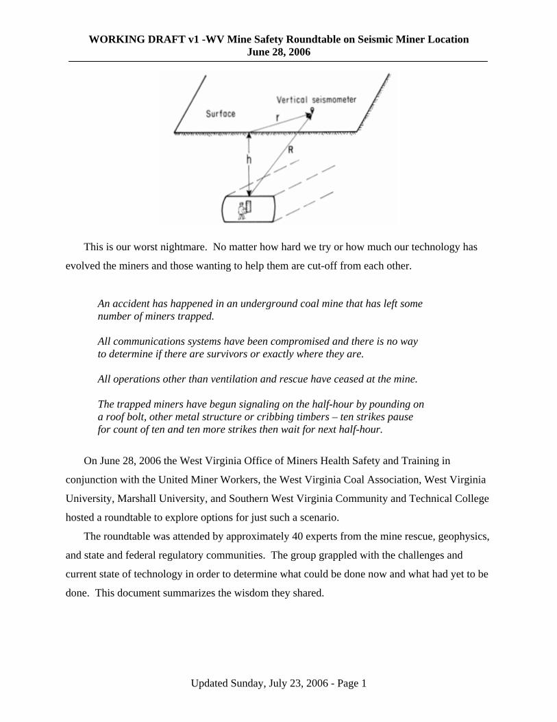
This is our worst nightmare. No matter how hard we try or how much our technology has
evolved the miners and those wanting to help them are cut-off from each other.
An accident has happened in an underground coal mine that has left some number of miners trapped. All communications systems have been compromised and there is no way to determine if there are survivors or exactly where they are. All operations other than ventilation and rescue have ceased at the mine. The trapped miners have begun signaling on the half-hour by pounding on a roof bolt, other metal structure or cribbing timbers – ten strikes pause for count of ten and ten more strikes then wait for next half-hour.
On June 28, 2006 the West Virginia Office of Miners Health Safety and Training in
conjunction with the United Miner Workers, the West Virginia Coal Association, West Virginia
University, Marshall University, and Southern West Virginia Community and Technical College
hosted a roundtable to explore options for just such a scenario.
The roundtable was attended by approximately 40 experts from the mine rescue, geophysics,
and state and federal regulatory communities. The group grappled with the challenges and
current state of technology in order to determine what could be done now and what had yet to be
done. This document summarizes the wisdom they shared.
Updated Sunday, July 23, 2006 - Page 1
WORKING DRAFT v1 -WV Mine Safety Roundtable on Seismic Miner Location June 28, 2006
WHAT IS MEANT BY SEISMIC LOCATION?
Seismic sound waves travel through the Earth. They follow paths bent by the varying
density and composition of the earth's geology. This effect is similar to the refraction of light
waves. There are two kinds of body waves: primary (P-waves) and secondary (S-waves).
P waves are longitudinal or compression waves, which means that the ground is
alternately compressed and dilated in the direction of propagation.
These waves generally travel slightly less than twice as fast as S waves
and can travel through any type of material. In air, these pressure waves
take the form of sound waves; hence they travel at the speed of sound.
Typical speeds are 330 m/s in air, 1450 m/s in water and about 5000
m/s in granite. P waves are sometimes called "primary waves".
S waves are transverse or shear waves, which mean that the
ground is displaced perpendicularly to the direction of propagation. In the case of horizontally
polarized S waves, the ground moves alternately to one side and then the other. S waves can
travel only through solids, as fluids (liquids and gases) do not support shear stresses. Their speed
is about 60% of that of P waves in a given material. S waves are sometimes called "secondary
waves", and are several times larger amplitude than the P waves.
The difference in the arrival times of the P and S waves are used to determine the distance to the
event that created the sound. The difference between multiple receiving locations allows the
determination of the hypocenter (below the center) which is the location inside the earth where a
sound originated. The information can be manipulated in several ways including creation of
images as in ultrasound.
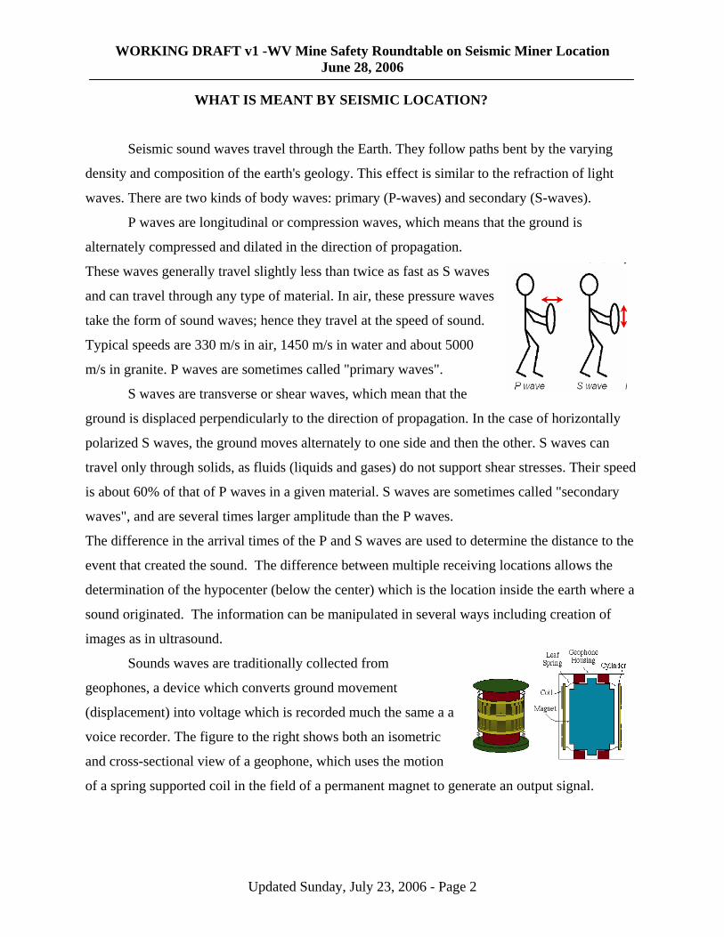
Sounds waves are traditionally collected from
geophones, a device which converts ground movement
(displacement) into voltage which is recorded much the same a a
voice recorder. The figure to the right shows both an isometric
and cross-sectional view of a geophone, which uses the motion
of a spring supported coil in the field of a permanent magnet to g
enerate an output signal.
Updated Sunday, July 23, 2006 - Page 2
WORKING DRAFT v1 -WV Mine Safety Roundtable on Seismic Miner Location June 28, 2006
Active seismic image mapping has c
billion dollar business. Seismic recording
systems with thousands of channels, fleets
of vibrators trucks operating in tandem
helicopter supported field operations are
commonplace. A conventional seismic set
consisting of a dynamite source,
receivers (geophones) and a recording truck
The lines represent the path of the soun
waves that travel down to the target and reflect back to the surface. Modern 3-D crews lay out
thousands of geophones and miles of cable on the ground.
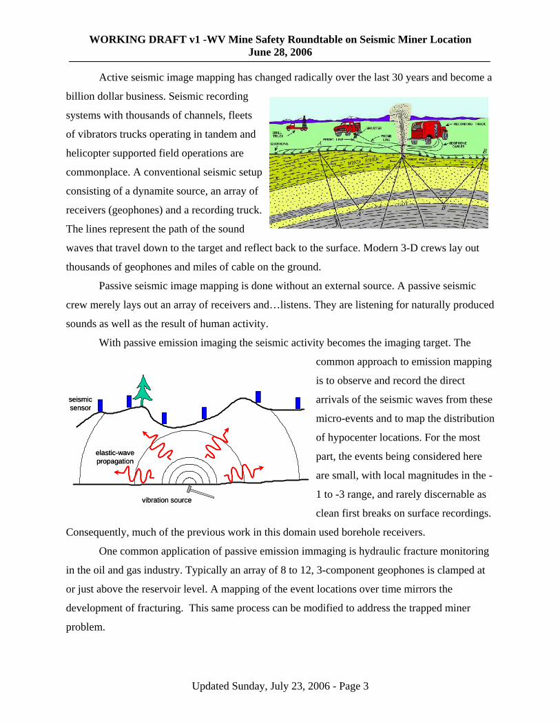
Passive seismic image mapping is done
hanged radically over the last 30 years and become a
and
up
an array of
.
d
without an external source. A passive seismic
crew m ed
ic activity becomes the imaging target. The
ing
hese
e most
he -
s.
Consequently, much of the previous work in this domain
nd gas industry. Typically an array of 8 to 12, 3-component geophones is clamped at
or just
erely lays out an array of receivers and…listens. They are listening for naturally produc
sounds as well as the result of human activity.
With passive emission imaging the seism
common approach to emission mapp
is to observe and record the direct
arrivals of the seismic waves from t
micro-events and to map the distribution
of hypocenter locations. For th
part, the events being considered here
are small, with local magnitudes in t
1 to -3 range, and rarely discernable as
clean first breaks on surface recording
used borehole receivers.
One common application of passive emission immaging is hydraulic fracture monitoring
in the oil a
vibration source
elastic-wavepropagation
seismicsensor
vibration source
elastic-wavepropagation
seismicsensor
above the reservoir level. A mapping of the event locations over time mirrors the
development of fracturing. This same process can be modified to address the trapped miner
problem.
Updated Sunday, July 23, 2006 - Page 3

WORKING DRAFT v1 -WV Mine Safety Roundtable on Seismic Miner Location June 28, 2006
The illustration to the right shows a surface method of passive
emission imaging. The signal from the miners would
cause a seismic signal that is recorded on the surface array.
As the
e. The
ation
ing higher energy levels. The areas
rface.
The currently available trapped miner
seismic location
S Mine Safety and Health Administration’s
ck to
ine
ou
6. The
enera
ogy since the 1970’s has come with enhanced
een some improvements and there are new
sound is tracked the computer calculates the location
based upon the time the signal arrives at each geophon
seismic energy recorded by the array over a period of observ
time is displayed as colors in the cube, hotter colors represent
of high energy will delineate where the activity is taking place in the subsu
WHAT IS THE STATE OF THE TECHNOLOGY?
equipment is owned by the
U
Mine Emergency Operations branch and is
located at the Pittsburgh facility.
The rig is composed of three vehicles;
an equipment truck that contains the
records and filters, a generator tru
provide power and trailer which
carries geophones, cables, and other
supplies. While it was deployed
during the Quecreek Number 1 M
inundation in July 2002, it was not br
the Sago explosion in January 200
system was built under contract with
Westinghouse in the 1970’s. There have been
some moderations over the years but it is g
The biggest change in the technol
computer capability. The basic geophone has s
ght to
lly agreed that it is in need to replacement.
Updated Sunday, July 23, 2006 - Page 4
WORKING DRAFT v1 -WV Mine Safety Roundtable on Seismic Miner Location June 28, 2006
digital sensors that have been introduced but the ability to use software to recognize a
filter the waveforms received has allowed for greatest advances in resolution.
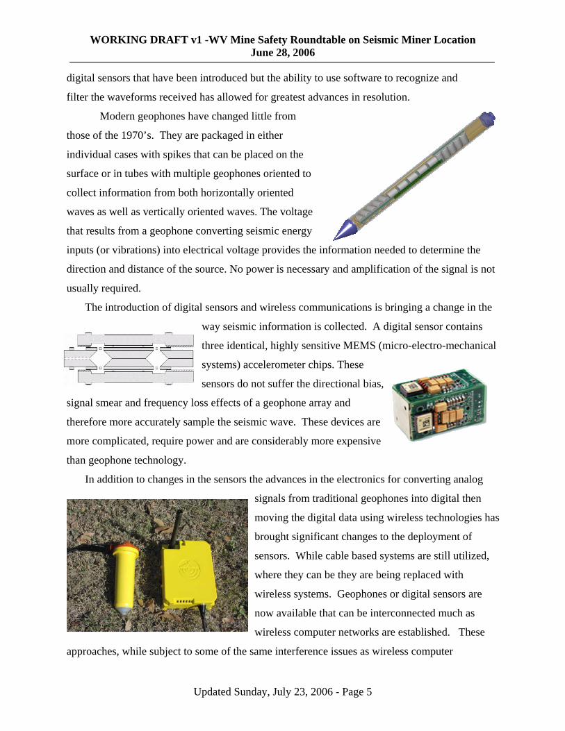
Modern geophones have changed little from
those of the 1970’s. They are packaged in either
nd
ed to
gy
in
ry and amplification of the signal is not
is collected. A digital sensor contains
therefore more accurately sam
nsive
signals from traditional geophones into digital then
,
s
individual cases with spikes that can be placed on the
surface or in tubes with multiple geophones orient
collect information from both horizontally oriented
waves as well as vertically oriented waves. The voltage
that results from a geophone converting seismic ener
inputs (or vibrations) into electrical voltage provides the
direction and distance of the source. No power is necessa
usually required.
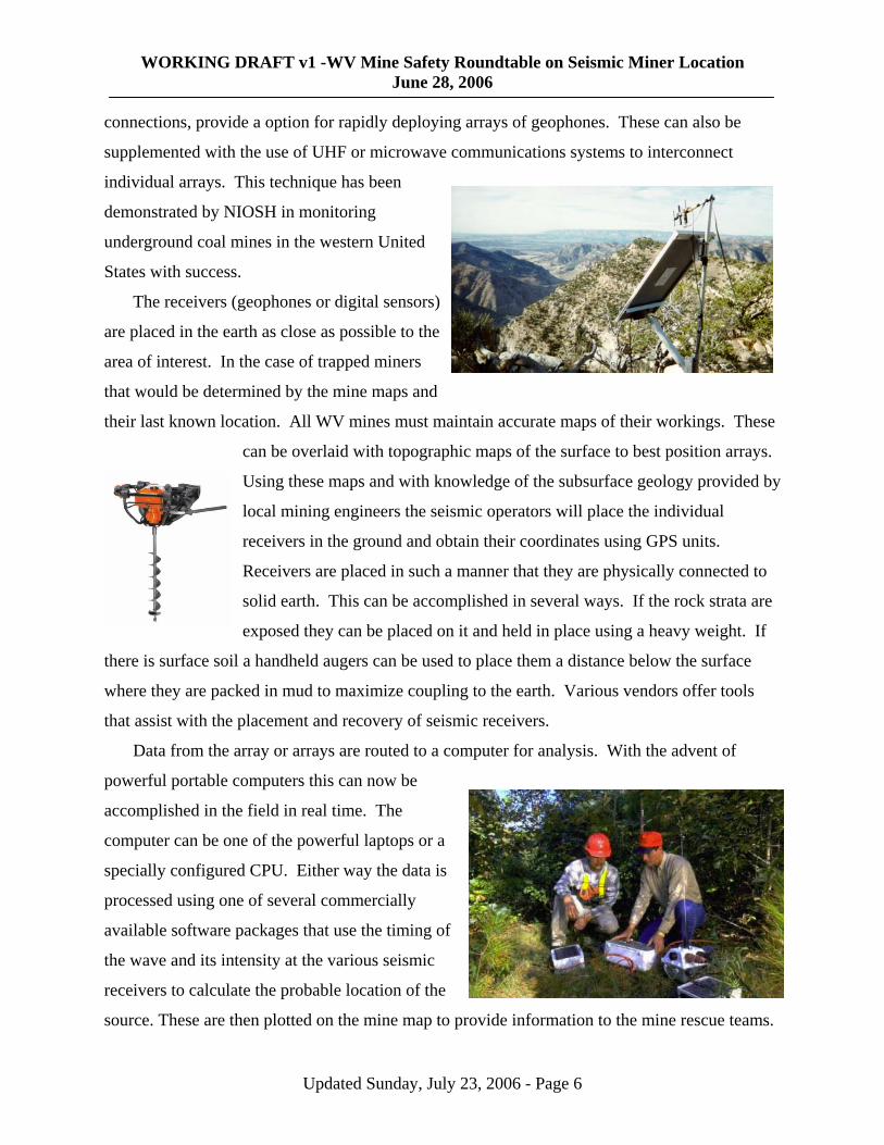
The introduction of digital sensors and wireless communications is bringing a change in the
way seismic information
formation needed to determine the
three identical, highly sensitive MEMS (micro-electro-mechanical
systems) accelerometer chips. These
sensors do not suffer the directional bias,
ss effects of a geophone array and
ple the seismic wave. These devices are
more complicated, require power and are considerably more expe
than geophone technology.
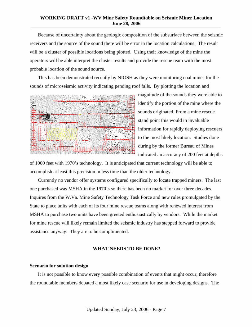
In addition to changes in the sensors the advances in the electronics
signal smear and frequency lo
for converting analog
moving the digital data using wireless technologies has
brought significant changes to the deployment of
sensors. While cable based systems are still utilized
where they can be they are being replaced with
wireless systems. Geophones or digital sensors are
now available that can be interconnected much as
wireless computer networks are established. These
ame interference issues as wireless computer approaches, while subject to some of the
Updated Sunday, July 23, 2006 - Page 5
WORKING DRAFT v1 -WV Mine Safety Roundtable on Seismic Miner Location June 28, 2006
connections, provide a option for rapidly deploying arrays of geophones. These can also be
supplemented with the use of UHF or microwave communications systems to interconnect
individual arrays. This technique has been
demonstrated by NIOSH in monitoring
underground coal mines in the western
States with success.
The receivers (geophones or digi
United
tal sensors)
e to the
rs
d
aphic maps of the surface to best position arrays.
vided by
to
where they are pack
of
r a
ata is
c
o p
are placed in the earth as close as possibl
area of interest. In the case of trapped mine
that would be determined by the mine maps an
their last known location. All WV mines must m
can be overlaid with topogr
Using these maps and with knowledge of the subsurface geology pro
local mining engineers the seismic operators will place the individual
receivers in the ground and obtain their coordinates using GPS units.
Receivers are placed in such a manner that they are physically connected
solid earth. This can be accomplished in several ways. If the rock strata are
exposed they can be placed on it and held in place using a heavy weight. If
a handheld augers can be used to place them a distance below the surface
ed in mud to maximize coupling to the earth. Various vendors offer tools
that assist with the placement and recovery of seismic receivers.
Data from the array or arrays are routed to a computer for analysis. With the advent
powerful portable computers this can now be
aintain accurate maps of their workings. These
there is surface soil
accomplished in the field in real time. The
computer can be one of the powerful laptops o
specially configured CPU. Either way the d
processed using one of several commercially
available software packages that use the timing of
the wave and its intensity at the various seismi
receivers to calculate the probable location of the
source. These are then plotted on the mine map t rovide information to the mine rescue teams.
Updated Sunday, July 23, 2006 - Page 6
WORKING DRAFT v1 -WV Mine Safety Roundtable on Seismic Miner Location June 28, 2006
Because of uncertainty about the geologic composition of the subsurface between the seismic
receivers and the source of the sound there will be error in the location calculations. The result
he
g pending roof falls. By plotting the location and
e the
rs
one
s
accomplish at least this precision in less time than the
ast
over three decades.
BE DONE?
Scenario for solution design
It is not possible to know every possible combination of events that might occur, therefore
d a most likely case scenario for use in developing designs. The
will be a cluster of possible locations being plotted. Using their knowledge of the mine the
operators will be able interpret the cluster results and provide the rescue team with the most
probable location of the sound source.
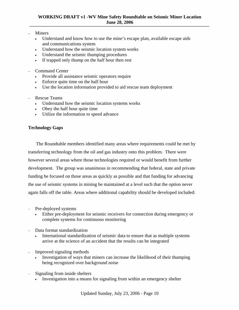
This has been demonstrated recently by NIOSH as they were monitoring coal mines for t
sounds of microseismic activity indicatin
magnitude of the sounds they were able to
identify the portion of the mine wher
sounds originated. From a mine rescue
stand point this would in invaluable
information for rapidly deploying rescue
to the most likely location. Studies d
during by the former Bureau of Mines
indicated an accuracy of 200 feet at depth
that current technology will be able to
older technology.
Currently no vendor offer systems configured specifically to locate trapped miners. The l
one purchased was MSHA in the 1970’s so there has been no market for
of 1000 feet with 1970’s technology. It is anticipated
Inquires from the W.Va. Mine Safety Technology Task Force and new rules promulgated by the
State to place units with each of its four mine rescue teams along with renewed interest from
MSHA to purchase two units have been greeted enthusiastically by vendors. While the market
for mine rescue will likely remain limited the seismic industry has stepped forward to provide
assistance anyway. They are to be complimented.
WHAT NEEDS TO
the roundtable members debate
Updated Sunday, July 23, 2006 - Page 7

WORKING DRAFT v1 -WV Mine Safety Roundtable on Seismic Miner Location June 28, 2006
group concluded that as the technology and techniques are refined the elements may need tio be
modified but for the initial design basis a reasonable starting point is:
− An accident has happened in an underground coal mine that has left some number of miners trapped
ne and determine who is missing and where they were last • Determine likely problem – explosion, fire, gas, water, etc
− aling by thumping a roof bolt with a timber or hammer. On
times followed by delay of a ten count and another ten thumps. Then they rest until the next half hour.
−
s are trying to communicate seismically • Where on the mine map miners are with as much accuracy as possible
− ches and
emergency shelter/chamber locations noted eological conditions and access to the mine
• ne and internet
• he surface over the mine
, etc) on the half hours ish common extraneous noises
ls
Tec no
d some general requirements based upon experience in mine
scue and applied geophysics. These will need to be reviewed as the technology and
− All operations other than ventilation and rescue have ceased at the mine • Evacuate mi
• Terminate power • Establish gas monitoring
The miners begin signeach half hour they thump ten
Mine Rescue Teams supported by seismic location equipment and operators have been deployed
− The seismic operators need to determine:
• If the miner
The seismic operators have: • An accurate surface and mine maps with escape-ways, SCSR storage ca
• An understanding of the gengineer/geophysicist Access to consulting seismic experts via pho
• An understanding of the last known location of the miners Unrestricted access to t
• GPS capability to locate their geophones • Ability to silence extraneous noise (i.e., stop traffic, drilling• Experience in listening to mines so as to distingu
such as pumps, fans, etc from miner signa
h logy Requirements
The roundtable develope
re
techniques are further refined to correct any shortcomings and take advantage of new
capabilities.
Updated Sunday, July 23, 2006 - Page 8

WORKING DRAFT v1 -WV Mine Safety Roundtable on Seismic Miner Location June 28, 2006
− Portable
• Small enough to carry in regular vehicles from regional offices to the mine • Require no power beyond batteries that can be carried into the field
oyed
h to survive repeated use in training and still work when needed
− rovide the on-site
ficient precision to aid rescue team
• ts to
Pro d
In addition to the technology there are several areas where procedures must be
to ensure the seismic location system to function. Some of
ese relate to how the equipment is used others to how miners and rescuers must react.
velocity constants, void recognition, loosely compacted areas, etc)
− ei
• nal checklists that minimize possibility of operator s
− Easily depl
• Ability to deploy in no more than 60 minutes once arriving at the mine • Ability to move quickly if need to refine location • Ability to interconnect with additional units as they arrive • Rugged enoug
Simple to operate • As much as possible the software should be automated to p
technician the ability to operate • Ability to produce accurate results in real-time (estimates of location on mine
maps) with suf• Ability to produce maps to inform command staff and mine rescue teams Ability to save and transmit collected seismic data to consulting seismic exper
assist in interpretation
ce ural Requirements
developed and implemented
th
− Mine Operators • Prepare and provide accurate mine and topographic maps in the same coordinate
system in a format that will be accepted by the seismic software • Prepare and provide geologic information as needed by seismic team to calibrate
the software (• Secure necessary access to surface areas that are needed for seismic operations in
the evident of an accident
S smic Operators • Review each mine in their region and plan through system setup and operation • Develop and maintain mine specific velocity and other variable values
Detailed setup and operatioerror under stres
• Practice transport, setup and operation and know how to make necessary corrections and repairs under field conditions
• Maintain interactions with other operators and consulting seismic experts to minimize chance of miscommunications under stress
Updated Sunday, July 23, 2006 - Page 9
WORKING DRAFT v1 -WV Mine Safety Roundtable on Seismic Miner Location June 28, 2006
−
• cape plan, available escape aids
•
• Understand the seismic thumping procedures • If trapped only thump on the half hour then rest
− • operators require
scue team deployment
Rescue Teams the seismic location systems works
ance
ec
h ents could be met by
ansferring technology from the oil and gas industry onto this problem. There were
as where those technologies required or would benefit from further
evelopment. The group was unanimous in recommending that federal, state and private
er
:
Data format standardization • International standardization of seismic data to ensure that as multiple systems
of an accident that the results can be integrated − Imp
• Investigation of ways that miners can increase the likelihood of their thumping kground noise
− Sig
• Investigation into a means for signaling from within an emergency shelter
Miners Understand and know how to use the mine’s esand communications system Understand how the seismic location system works
Command Center
Provide all assistance seismic• Enforce quite time on the half hour • Use the location information provided to aid re
− • Understand how• Obey the half hour quite time • Utilize the information to speed adv
T hnology Gaps
T e Roundtable members identified many areas where requirem
tr
however several are
d
funding be focused on those areas as quickly as possible and that funding for advancing
the use of seismic systems in mining be maintained at a level such that the option nev
again falls off the table. Areas where additional capability should be developed included
− Pre-deployed systems • Either pre-deployment for seismic receivers for connection during emergency or
complete systems for continuous monitoring −
arrive at the science
roved signaling methods
being recognized over bac
naling from inside shelters
Updated Sunday, July 23, 2006 - Page 10
WORKING DRAFT v1 -WV Mine Safety Roundtable on Seismic Miner Location June 28, 2006
− Ideal set of available geologic information
ease signal recognition and location precision
− Opt
• ptions for use of a network of seismic experts that could assist operators is of data using the internet
− Pre
• Explore options for maintaining accurate mine and topo maps such that teams can eview on the way to the mine
− Opt
• Explore uses for trapped miner seismic location systems in support of other
ct
Th elieve that there is sufficient information to move to begin
implementing a seismic trapped miner location program now. While there are long term
t could enhance such a system’s performance, it should work now and there is
o reason to wait. The following are actions recommended:
dated as technology
OW – Collect necessary mine specific information
formation and the system for
BY NO
of the deployable configuration
• Investigate what is the minimal required geologic information required to calibrate a seismic location system to incr
− Noise pattern library • Develop a library of typical noises that can be shared by seismic operators
(pumps, fans, etc)
ions for remote analysis Develop oin real-time analys
loaded mine maps
have them download for r
ions for use in other emergencies
emergency operations
A ions
e roundtable members b
issues tha
n
NOW – Develop configuration for deployable seismic units
• Utilizing the best available off-the-shelf technologies configure a system that willmeet the requirements and be flexible enough to be upchanges
N
• Start the process of determining the minimal set of ingathering and maintaining it
VEMBER – Test configuration
• As soon as possible begin testing the elements
Updated Sunday, July 23, 2006 - Page 11
WORKING DRAFT v1 -WV Mine Safety Roundtable on Seismic Miner Location June 28, 2006
BY DECEMBER – Acquire four units and train operators
eet the States configuration requirements and
OW – Incorporate seismic options in tests of mine communications systems
r identify opportunities for egrated systems
NO –
U and MSHA to establish a national forum for seismic professions iner
NOW – establish the
• Acquire four seismic units that mbegin training
N
• As communication testing is being done this summeincorporating installed seismic elements into the int
W Developing national workgroup on trapped miner seismic location
Work with WV•
focused upon mining applications with a special emphasis of trapped mlocation
Begin working the State, Federal, non-profit groups and industry to resources necessary to address the technology gaps identified above
Updated Sunday, July 23, 2006 - Page 12