Embed Size (px)
Citation preview

Red Hill Facility Tank Upgrade Alternatives Scope of Work 8 September 2016
Red Hill Administrative Order on Consent Scope of Work Deliverable
Section: 3.2 Tank Upgrade Alternatives (TUA) Scope of Work.
In accordance with the Red Hill Administrative Order on Consent, paragraph 9, DOCUMENT CERTIFICATION
I certify under penalty of law that this document and all attachments were prepared under my direction or supervision in accordance with a system designed to assure that qualified personnel properly gather and evaluate the information submitted. Based on my inquiry of the person or persons who manage the system or those persons directly responsible for gathering the information, the information submitted is, to the best of my knowledge and belief, true, accurate, and complete. I am aware that there are significant penalties for submitti false information including the possibility of fines and imprisonment for knowi g violafo
.D.Signature:
CAPT R. D. Ha es I I, CEC, USN Regional Engineer, l'Javy Region Hawaii
Date:
1

Contract N62742-13-0-0001 , Delivery Order 0009
3.2 TANK UPGRADE ALTERNATIVES (TUA)
Scope of Work Outline Final Submission September 2016
RED HILL FUEL STORAGE FACILITY NAVSUP FLC PEARL HARBOR, HI (PRL)
Joint Base Pearl Harbor-Hic kam
Administrative Order on Consent In the matter of Red Hill Bulk Fuel Storage Facility EPA Doc ket No. RCRA 7003-R9-2015-01 DOH Doc ket No. 15-UST-EA-01
Contract Agency:
II NAVFAC Pacific ~ 258 Makalapa Drive, Suite 100
JBPHH Hawaii 96860-3134 NWFiAC
Prime Contract:
L 1111\~ Engineering, Inc. r J~ 1132 Bishop Street, Suite 1200 Honolulu, Hawaii 96813-2822
Prepared By: ______............_ ____ _,__.....__-·-. -··· ......_ENGINEERING, INC.
5 Depot Street, Freeport, Maine 04032
EEi Project No. 8290
Draft, Pre- Decisional, Do Not Cite or Quote, For Discussion Purposes Only

Draft, Pre- Decisional, Do Not Cite or Quote, For Discussion Purposes Only

Page Intentionally Left Blank

Draft, Pre- Decisional, Do Not Cite or Quote, For Discussion Purposes Only
AOC SOW SECTION 3
TABLE OF CONTENTS
Page
1.0 EXECUTIVE SUMMARY ........................................................................................................... ...............................................................................................................................
.......................................................................................................... .................................................................................
...........................................................................
1 1.1 Introduction 1 1.2 Assessment Methodology 1 1.3 Step 1: Available Technology Screening 1 1.4 Step 2: Secondary Screening of Alternatives 1 1.5 Step 3: Assessment of BAPT Tank Upgrade Alternatives .......................................................
.......................................................................................... .............................
........................................ ..............................................
.......................................................................................... ........................................................................................................
...................................................... ......................................................................................
........................................................... .....................................................................................................
............................................................................................ ..............................................................................
1 1.6 Related Work Completed by Others 1
1.6.1 AOC Section 2: Tank Inspection, Repair and Maintenance (TIRM) 1 1.6.2 AOC Section 4: Release Detection / Tank Tightness Testing 1 1.6.3 AOC Section 5: Corrosion and Metal Fatigue Practices 2
1.7 Construction Execution Challenges 2 1.7.1 Construction Power 2 1.7.2 Data Collection (Lower Tunnel Fiber Optic Needs) 2 1.7.3 Staging and Material Handling 2 1.7.4 Access to Tank Lining for Inspection and Repair 2
1.8 Execution Scheduling Issues 2 1.8.1 Number of Tanks at a Time 2 1.8.2 Acquisition Strategy Considerations 2
1.9 Pilot Programs ........................................................................................................................... 2
2.0 EXISTING TANK CONSTRUCTION/CONFIGURATION .................................................... 3 2.1 Background ............................................................................................................................... 3 2.2 Tank Construction/Configuration..............................................................................................3 2.3 Historical Structural and Integrity Issues .................................................................................. 5 2.4 Non-Structural and Hydraulic Issues ......................................................................................... 6 2.5 Impact of Tank Construction/Configuration on Upgrades ........................................................ 6
3.0 STEP 1: AVAILABLE TECHNOLOGY SCREENING........................................................... 7 3.1 Introduction ............................................................................................................................... 7 3.2 Key Background Documents ..................................................................................................... 7 3.3 Resources Consulted ................................................................................................................. 7 3.4 Process Methodology ................................................................................................................ 7 3.5 Candidate Technologies and Initial Screening .......................................................................... 8 3.6 Available Tank Upgrade Technologies ..................................................................................... 8
3.6.1 Single Wall Tank Interior Upgrades .............................................................................. 8 3.6.2 Upgrades to Provide Secondary Containment with Release Detection ....................... 12 3.6.3 Tank Exterior Upgrades ............................................................................................... 14
3.7 Screening Criteria Definitions................................................................................................. 16
4.0 STEP 2: SECONDARY SCREENING OF ALTERNATIVES ............................................... 1 4.1 Tank Upgrade Alternatives – Summary of BAPTs Considered ................................................ 1 4.2 Secondary Screening Methodology ........................................................................................... 1
3.0 Tank Upgrade Alternatives (TUA) TABLE OF CONTENTS Red Hill Fuel Storage Facility Draft SOW Outline EEI Project 8290, HDR Project 258050 September 2016

Draft, Pre- Decisional, Do Not Cite or Quote, For Discussion Purposes Only
AOC SOW SECTION 3
TABLE OF CONTENTS
4.3 Review of Candidate Alternatives............................................................................................. 1 4.3.1 Alt 1A: Restoration of Tank ............................................................................................ 1 4.3.2 Alt 1B: Restoration of Tank plus Interior Coating ......................................................... 1 4.3.3 Alt 1C: Restoration of Tank plus Metalizing .................................................................. 1 4.3.4 Alt 1D: Remove Existing Steel Liner, Install New Liner ............................................... 1 4.3.5 Alt 1E: Rubber Liner Bonded to Existing Steel ............................................................. 1 4.3.6 Alt 2A: Composite Tank – Carbon Steel......................................................................... 1 4.3.7 Alt 2B: Composite Tank – Stainless Steel ....................................................................... 1 4.3.8 Alt 3A: Tank in Tank – Carbon Steel............................................................................. 1 4.3.9 Alt 3B: Tank in Tank – Stainless Steel............................................................................ 1 4.3.10 Alt 4: Double Wall Fiberglass with Release Detection .................................................. 1 4.3.11 Alt 5A: Steel Plates Welded to Existing Liner ............................................................... 2 4.3.12 Alt 5B: Steel Plates Welded to Existing Liner with Mesh in Interstice .......................... 2 4.3.13 Alt 6: Stainless Steel Membrane welded to Existing Steel Liner ................................... 2 4.3.14 Alt 7: Flexible Membrane Liner .................................................................................... 2
4.4 Table 4-1 Tank Upgrade Alternatives Evaluated ...................................................................... 2 4.5 Sub-Alternatives................................................................................................................... 7
4.5.1 Tell-Tale System .......................................................................................................... 7 4.5.2 Tank Nozzles................................................................................................................... 7
5.0 STEP 3: ASSESSMENT OF BAPT TANK UPGRADE ALTERNATIVES........................... 8 5.1 Alternatives Considered ............................................................................................................ 8 5.2 BAPT Attribute Definitions and Ranking System .................................................................... 8 5.3 Alternatives ............................................................................................................................. 15
5.3.1 Alternative 1A – Restoration of Tank ........................................................................... 16 5.3.2 Alternative 1B – Restoration of Tank plus Interior Coating ........................................ 17 5.3.3 Alternative 1D – Remove Steel Liner, Install New Liner .............................................. 18 5.3.4 Alternative 2A – Composite Tank (Double Wall) Carbon Steel ................................... 19 5.3.5 Alternative 2B – Composite Tank (Double Wall) Duplex Stainless Steel..................... 36 5.3.6 Alternative 3A – Tank within a Tank (Carbon Steel) ................................................... 37
5.4 BAPT Tank Upgrade Decision Matrix.................................................................................... 39
6.0 CONSTRUCTION EXECUTION ISSUES............................................................................... 47 6.1 Staging and Material Handling ................................................................................................ 47
6.1.1 Contractor Yard and Laydown..................................................................................... 47 6.1.2 Tunnel Access to Tanks ................................................................................................ 47
6.2 Temporary Electrical Power .................................................................................................... 47 6.2.1 Existing Electrical Power at Red Hill .......................................................................... 47 6.2.2 Temporary Power Supply ............................................................................................. 47 6.2.3 Temporary Tank Repair Electrical System ................................................................... 47
6.3 Data Communication – Fiber Optics ....................................................................................... 47 6.3.1 Existing Conditions ...................................................................................................... 47 6.3.2 Need for New Fiber Optic Communications ................................................................ 47
6.4 Tank Access Shaft ................................................................................................................... 47
3.0 Tank Upgrade Alternatives (TUA) TABLE OF CONTENTS Red Hill Fuel Storage Facility Draft SOW Outline EEI Project 8290, HDR Project 258050 September 2016

Draft, Pre- Decisional, Do Not Cite or Quote, For Discussion Purposes Only
AOC SOW SECTION 3
TABLE OF CONTENTS
6.4.1 Access for Power and Ventilation to Tank ................................................................... 47 6.5 Tank Staging Concepts for Work ............................................................................................ 47
6.5.1 Existing-Center Column Booms ................................................................................... 47 6.5.2 Erect conventional Staging ........................................................................................... 47 6.5.3 Erect Trolley and Multiple Platforms around Perimeter ............................................. 47
6.6 Tank Ventilation and Dehumidification .................................................................................. 47 6.6.1 Welding Ventilation Requirements ............................................................................... 47 6.6.2 Coating Ventilation and Dehumidification Requirements ............................................ 47
6.7 Construction Schedule............................................................................................................. 48
7.0 RELATED AOC INITIATIVES ................................................................................................ 49 7.1 Tank Inspection Repair and Maintenance (TIRM) ................................................................. 49 7.2 Release Detection / Tank Tightness Testing ........................................................................... 49 7.3 Corrosion and Metal Fatigue Practices Report ........................................................................ 49
8.0 COST ESTIMATES .................................................................................................................... 50 8.1 Cost Estimate Summaries ........................................................................................................ 50
9.0 DEFINITIONS ............................................................................................................................. 51
10.0 ABBREVIATIONS AND ACRONYMS .................................................................................... 52
11.0 REFERENCES............................................................................................................................. 53
12.0 PROJECT TEAM........................................................................................................................ 54
13.0 QUALITY CONTROL PROGRAM.......................................................................................... 54
APPENDICES
List of Appendices
LIST OF TABLES
TABLE 3-1 CANDIDATE TANK UPGRADE TECHNOLOGIES
TABLE 4-1 TANK UPGRADE ALTERNATIVES EVALUATED (SUMMARY)
TABLE 5-1 BAPT ATTRIBUTE DEFINITIONS AND RANKING SYSTEM
TABLE 5-2.1A BAPT ALT-1A: RESTORATION OF TANK (similar to current approach)
3.0 Tank Upgrade Alternatives (TUA) TABLE OF CONTENTS Red Hill Fuel Storage Facility Draft SOW Outline EEI Project 8290, HDR Project 258050 September 2016

Draft, Pre- Decisional, Do Not Cite or Quote, For Discussion Purposes Only
AOC SOW SECTION 3
TABLE OF CONTENTS
TABLE 5-2.1B BAPT ALT-1B: RESTORATION OF TANK PLUS INTERIOR COATING
TABLE 5-2.1D BAPT ALT-1D: REMOVE STEEL LINER, INSTALL NEW LINER
TABLE 5-2.2A BAPT ALT-2A: COMPOSITE TANK (Double wall) CARBON STEEL
TABLE 5-2.2B BAPT ALT-2B: COMPOSITE TANK (Double wall) DUPLEX STAINLESS STEEL
TABLE 5-2.3A BAPT ALT-3A: TANK WITHIN A TANK (CARBON STEEL)
TABLE 5-3 TANK UPGRADE ALTERNATIVES - BAPT DECISION MATRIX
3.0 Tank Upgrade Alternatives (TUA) TABLE OF CONTENTS Red Hill Fuel Storage Facility Draft SOW Outline EEI Project 8290, HDR Project 258050 September 2016
Draft, Pre- Decisional, Do Not Cite or Quote, For Discussion Purposes Only
Page Intentionally Left Blank

Draft, Pre- Decisional, Do Not Cite or Quote, For Discussion Purposes Only
3.0 TANK UPGRADE ALTERNATIVES (TUA)
Draft Scope of Work Outline Submission January 2016
RED HILL FUEL STORAGE FACILITY NAVSUP FLC PEARL HARBOR, HI (PRL)
Joint Base Pearl Harbor-Hickam
1.0 EXECUTIVE SUMMARY
The Executive Summary (Under Development)
1.1 Introduction
To include a discussion on the purpose of the study as defined by the AOC SOW paragraph 3.0
1.2 Assessment Methodology
1.3 Step 1: Available Technology Screening
1.4 Step 2: Secondary Screening of Alternatives
1.5 Step 3: Assessment of BAPT Tank Upgrade Alternatives
1.6 Related Work Completed by Others
1.6.1 AOC Section 2: Tank Inspection, Repair and Maintenance (TIRM)
1.6.2 AOC Section 4: Release Detection / Tank Tightness Testing
3.2 Tank Upgrade Alternatives (TUA) Red Hill Fuel Storage Facility EEI Project 8290, HDR Project 258050

Draft, Pre- Decisional, Do Not Cite or Quote, For Discussion Purposes Only
1.6.3 AOC Section 5: Corrosion and Metal Fatigue Practices
1.7 Construction Execution Challenges
1.7.1 Construction Power
1.7.2 Data Collection (Lower Tunnel Fiber Optic Needs)
1.7.3 Staging and Material Handling
1.7.4 Access to Tank Lining for Inspection and Repair
1.8 Execution Scheduling Issues
1.8.1 Number of Tanks at a Time
1.8.2 Acquisition Strategy Considerations
1.9 Pilot Programs
3.2 Tank Upgrade Alternatives (TUA) Red Hill Fuel Storage Facility EEI Project 8290, HDR Project 258050

Draft, Pre- Decisional, Do Not Cite or Quote, For Discussion Purposes Only
2.0 EXISTING TANK CONSTRUCTION/CONFIGURATION
The purpose of §2.0 is to set the stage for repairs and upgrades by introducing the basic concepts on how the tanks were originally built, to what standards (none), and how they have survived over the years. This w ill include some summary of past fa ilure mechanisms
sufficient to build on for the future
2.1 Background
The FLC Pearl Harbor Red Hill Bulk Fuel Storage Facility was constrncted during August 1940 to September 1943. The facility consists of twenty underground vertical cylindrical reinforced concrete fuel storage tanks (Tanks 1 - 20) with a dome top and dome bottom, internal steel liner, fuel piping, mechanical and ventilation systems, electrical systems, Upper Tunnel, Lower Tunnel, Adits 3, 4, 5, and 6, and associated infrastrncture. A 3+-mile tunnel connects the Tank Gallery area to the Underground Pumphouse at Pearl Harbor Naval facility.
The Upper Tunnel provides access to the tank manholes and gauging platforms. The Lower Tunnel provides access to the tank piping and valves. Adit 4 (located at Tanks 1 and 2) and Adit 5 (located between Tanks 13 and 15) provide access to the Upper Tunnel. Adit 3 provides access to the Lower Tunnel at Tanks 1 and 2. The only access into the tanks is via an 8 feet diameter manhole at the Upper Tunnel level.
Each tank has a steel framed tower in the center of the tank extending from the floor of the lower dome to the top of the upper dome with a walkway from the manhole at the Upper Tunnel level to the tower. The center tower was used during original construction to construct the tanks and remains in the tanks for maintenance and crane service.
Eighteen tanks are cunently in service and presently used to store military fuel as follows:
• Tanks 2 to 6: JP-8
• Tanks 7 to 12: JP-5
• Tanks 13 to 16: F-76
• Tanks 17, 18, 20: JP-5
Tank 1 and Tank 19 ar·e not in active service. Tank 19 was taken out ofservice circa 1986 for gauging repairs. The tank was not placed back in service.
The reason for taking Tank 1 out ofservice has not been disclosed.
2.2 Tank Construction/Configuration
3.2 Tank Upgrade Altema.tives (TUA) Red Hill Fuel Storage Facility EEi Project 8290, HDR Project 258050
Draft, Pre- Decisional, Do Not Cite or Quote, For Discussion Purposes Only
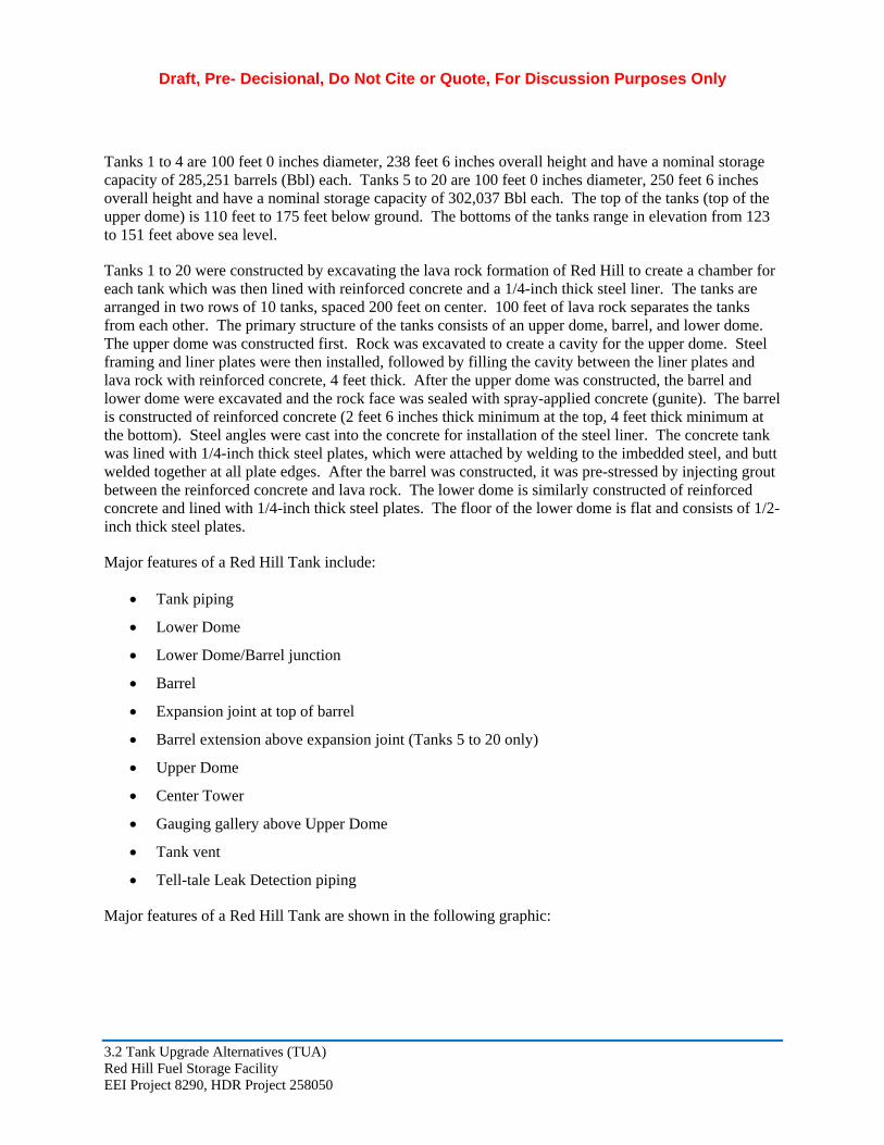
Tanks 1 to 4 are 100 feet 0 inches diameter, 238 feet 6 inches overall height and have a nominal storage capacity of 285,251 barrels (Bbl) each. Tanks 5 to 20 are 100 feet 0 inches diameter, 250 feet 6 inches overall height and have a nominal storage capacity of 302,037 Bbl each. The top of the tanks (top of the upper dome) is 110 feet to 175 feet below ground. The bottoms of the tanks range in elevation from 123 to 151 feet above sea level.
Tanks 1 to 20 were constructed by excavating the lava rock formation of Red Hill to create a chamber for each tank which was then lined with reinforced concrete and a 1/4-inch thick steel liner. The tanks are arranged in two rows of 10 tanks, spaced 200 feet on center. 100 feet of lava rock separates the tanks from each other. The primary structure of the tanks consists of an upper dome, barrel, and lower dome. The upper dome was constructed first. Rock was excavated to create a cavity for the upper dome. Steel framing and liner plates were then installed, followed by filling the cavity between the liner plates and lava rock with reinforced concrete, 4 feet thick. After the upper dome was constructed, the barrel and lower dome were excavated and the rock face was sealed with spray-applied concrete (gunite). The barrel is constructed of reinforced concrete (2 feet 6 inches thick minimum at the top, 4 feet thick minimum at the bottom). Steel angles were cast into the concrete for installation of the steel liner. The concrete tank was lined with 1/4-inch thick steel plates, which were attached by welding to the imbedded steel, and butt welded together at all plate edges. After the barrel was constructed, it was pre-stressed by injecting grout between the reinforced concrete and lava rock. The lower dome is similarly constructed of reinforced concrete and lined with 1/4-inch thick steel plates. The floor of the lower dome is flat and consists of 1/2-inch thick steel plates.
Major features of a Red Hill Tank include:
Tank piping
Lower Dome
Lower Dome/Barrel junction
Barrel
Expansion joint at top of barrel
Barrel extension above expansion joint (Tanks 5 to 20 only)
Upper Dome
Center Tower
Gauging gallery above Upper Dome
Tank vent
Tell-tale Leak Detection piping
Major features of a Red Hill Tank are shown in the following graphic:
3.2 Tank Upgrade Alternatives (TUA) Red Hill Fuel Storage Facility EEI Project 8290, HDR Project 258050

Draft, Pre- Decisional, Do Not Cite or Quote, For Discussion Purposes Only
2.3 Historical Structural and Integrity Issues
This discussion summarizes typical structural and integrity issues. Details of tank histories are provided in other AOC Sections by others. Structural and integrity issues relevant to repairing the tank for a future use consist of:
Internal corrosion and pitting,
External corrosion,
Holes in the steel liner requiring repair
Dents and bulges in liner plates that would interfere with repairs
Defective welds in the upper dome. Some tanks were repaired in the past by welding channels over defective welds. Other tanks were repaired by welding batten plates over defective welds. And some tanks were repaired by re-welding only the defective weld
3.2 Tank Upgrade Alternatives (TUA) Red Hill Fuel Storage Facility EEI Project 8290, HDR Project 258050

Draft, Pre- Decisional, Do Not Cite or Quote, For Discussion Purposes Only
Defective welds in the barrel and lower dome (intermittent cracks, lack of fusion, porosity, and slag inclusions) requiring repair
Failures (breaches) and internal corrosion in the leak detection piping (the leak detection piping in some of the tank has been removed)
Repairs to the center tower
Internal corrosion in the tank piping leading to the main headers in the lower tunnel
2.4 Non-Structural and Hydraulic Issues
Issues associated with tank leak detection, gauging, and release detection system upgrades are covered in AOC Section 4.
Additional material
Placeholder
2.5 Impact of Tank Construction/Configuration on Upgrades
Important and related issues of actual execution of inspections, repairs and upgrades for the Red Hill tanks are unique for tank work, but have been addressed in other construction projects.
Inspecting the barrel and upper dome involves working from suspended two-man baskets (scaffolding) supported from booms erected on the center tower, or erecting staging inside the tank. An additional alternative, to provide moveable suspended platforms on a trolley also should be investigated.
Repairs to the existing steel liner on the barrel involves working from suspended two-man baskets (scaffolding) supported from booms erected on the center tower, or erecting staging inside the tank. An additional alternative, to provide moveable suspended platforms on a trolley also should be investigated.
Repairs to the upper dome involves working from suspended two man-baskets (scaffolding).
Materials for tank upgrades can only be brought into the tanks via the upper tunnel, and must fit through the tunnel doors and tank manhole.
Recent tank cleaning, inspection, and repair projects at Red Hill tanks have identified critical deficiencies in obtaining power for construction.
The piping from the lower dome is encased in the concrete base below each tank. Providing new piping requires boring though approximately 45 feet of concrete to the lower tunnel. Alternatives for repair of exiting piping also need to be explored.
3.2 Tank Upgrade Alternatives (TUA) Red Hill Fuel Storage Facility EEI Project 8290, HDR Project 258050

Draft, Pre- Decisional, Do Not Cite or Quote, For Discussion Purposes Only
3.0 STEP 1: AVAILABLE TECHNOLOGY SCREENING
3.1 Introduction
Step 1 in the overall development of BAPT technology alternatives was completed to identify ideas on how the present tanks may be upgraded to improve integrity, reliability, and offer credible means of leak detection and/or containment.
3.2 Key Background Documents
The following key documents have addressed in the past, upgrade alternatives for the Red Hill Tanks:
1997 – Upgrade of Red Hill, Tank 19: EEI completed this study under contract to NAVFAC, to develop ideas for upgrades to out of service Tank 19.
2008 – Update to the 1997 Tank 19 report, and expansion to Upgrade of Red Hill Tanks (with fundamentally similar findings)
2008 – Market Survey of Leak Detection Systems for the Red Hill Fuel Storage Facility, Michael Baker Jr. Inc.
3.3 Resources Consulted
EEI, being involved in numerous tank repair projects throughout the world, has been exposed to and executed a wide variety of minor and major tank repairs, and new tank engineering projects. Many of the ideas developed as candidate technologies for Red Hill are based on our individual and corporate experiences.
Additional resources consulted for ideas include industry and military fuel tank managers, internet searches, construction contractors and colleagues in the business.
3.4 Process Methodology
Technologies are not singular in practice, and are a result of a combination of repair techniques that need to address the many unique characteristics of the Red Hill tanks. We refer to them as technologies based on the concept of similarity as to materials, or application. Most all in fact use common engineered materials such as steel and coatings formulated to provide corrosion prevention, or to bridge defects in the substrate.
The method of developing the candidates was similar to the brainstorming concept, wherein ideas were tossed out and recorded for additional discussion.
EEI used the following process to identify and evaluate available tank upgrade technologies under the Step 1 Methodology:
1. Identify candidate tank upgrade technologies. The technologies or upgrade concepts are grouped into the following categories:
a. Tank Interior Upgrades (Repair existing, coatings, liners, primarily single wall).
3.2 Tank Upgrade Alternatives (TUA) Red Hill Fuel Storage Facility EEI Project 8290, HDR Project 258050

Draft, Pre- Decisional, Do Not Cite or Quote, For Discussion Purposes Only
b. Upgrades to Provide Secondary Containment with Release Detection (Double wall, or diked)
c. Tank Exterior Upgrades (Technologies applied outside of the prima1y tank lining an concrete barTel)
2. Evaluate and screen candidate technologies for fmther investigation (summarized in Table 3-1) under Step 2 process.
3. Steps 2 take the results ofStep 1, and reduce the candidates to a final group of six (6) concepts for detailed evaluation as a BAPT technology during Step 3. Table 4-1 summarizes candidate technologies being screened in Step 2.
3.5 Candidate Technologies and Initial Screening
Paragraph 3.6 discusses the candidate technologies. Table 3-1 lists candidate technologies that EEi identified for tank upgrades. Screening of the technologies considering the following crite1ia:
• Feasible and Testable (after constrnction)
• Inspectable and Repairable (future integrity assessment)
See paragraph ???? for definitions ofscreening c1iteria. Technologies passing these criteria were selected for ftuther investigation as a pa1t of Step 2. Technologies not passing these crite1ia were not selected for ftuther investigation and comments ar·e provided as to justification. In the event a technology passes the four crite1ia but is not selected for ftuther investigation, comments as to reason for rejection ar·e provided.
See paragraph 3.6 for detailed descriptions ofcandidate technologies that EEi has identified for tank upgrades and initial screening.
3.6 Available Tank Upgrade Technologies
Table 3-1 summar·izes available technologies that EEi has identified for tank upgrades. The table identifies technologies that EEi selected for ftuther investigation and technologies not selected for ftuther investigations and reasons for rejection.
A variety ofsingle wall and double wall technologies were considered. Characteristics of the technologies ar·e ftuther described, including discussion on whether or not they were considered for ftuther evaluation.
3.6.1 Single Wall Tank Interior Upgrades
The following candidate interior upgrades represent initial brainstomling to upgrade the present tanks. Double walVseconda1y containment approaches discussion follows.
3.6.1.1 is an example of how the init ial list of candidate technologies w ill be 3.6.1.1 Repair ofExisting Tank Shell- Patch Plates and Welding presented and eit her accepted for moving forward, or rejected at this level General Description:
Alternative IA is similar· to the cmTent approach to inspect and repair the tanks but with enhanced TIRM procedures established to assure the full integrity of the existing steel liner is investigated for long-te1m
3.2 Tank Upgrade Alternatives (TUA) Red Hill Fuel Storage Facility EEi Project 8290, HDR Project 258050

Draft, Pre- Decisional, Do Not Cite or Quote, For Discussion Purposes Only
life extension repairs. Tank repairs include repairing pitting, holes, and defective welds (intermittent cracks, lack of fusion, porosity, and slag inclusions) in the existing steel liner. Alternative 1A also includes extensive repairs to present existing single wall concrete encased piping from the tank to the first valve outside tank or replacing the entire piping with double wall construction.
Practicable:
This general concept of tank upgrades is considered practicable based on being similar to what has already been done at Red Hill, as well as common application throughout the petroleum tank industry
Feasible and Testable (after construction): Yes
Inspectable and Repairable (future integrity assessment): Yes
Conclusion:
Overall, the inspection and repair is considered conventional construction, with the emphasis placed on thoroughness, with appropriate contractor Quality Control (QC) and government oversight and Quality Assurance program. This concept is advanced to Step 2 for additional consideration and assessment.
3.6.1.2 Replace/provide Tell Tale System
[Text – later] [Note: This is sub option that may apply to several alternatives]
3.6.1.3 Coating Systems on Existing Shell
[Generic coating discussion to be provided]
Epoxy Coating (Thin Film): xxx
[Text – later]
Polysulfide Modified Epoxy Novolac: xxx
[Text – later]
Urethane (Thin Film): xxx
[Text – later]
Polyurea (Thick Film): xxx
[Text – later]
Thermal Spray Aluminum (Metalizing): xxx
[Text – later]
3.2 Tank Upgrade Alternatives (TUA) Red Hill Fuel Storage Facility EEI Project 8290, HDR Project 258050

Draft, Pre- Decisional, Do Not Cite or Quote, For Discussion Purposes Only
Thermal Spray Ceramic: xxx
[Text – later]
Glass: xxx
[Text – later]
3.6.1.4 Lining Systems
[Generic discussions on lining systems]
3.6.1.5 Single Wall Fiberglass: xxx
General Description:
Practicable:
Feasible and Testable (after construction): xxx
Inspectable and Repairable (future integrity assessment): xxx
Conclusion:
3.6.1.6 Rubber Lining: xxx
General Description:
Practicable:
Feasible and Testable (after construction): xxx
Inspectable and Repairable (future integrity assessment): xxx
Conclusion:
3.6.1.7 Flexible Membrane: xxx
General Description:
Practicable:
Feasible and Testable (after construction): xxx
Inspectable and Repairable (future integrity assessment): xxx
3.2 Tank Upgrade Alternatives (TUA) Red Hill Fuel Storage Facility EEI Project 8290, HDR Project 258050

Draft, Pre- Decisional, Do Not Cite or Quote, For Discussion Purposes Only
Conclusion:
3.6.1.8 Carbon Fiber Sheet: xxx
General Description:
Practicable:
Feasible and Testable (after construction): xxx
Inspectable and Repairable (future integrity assessment): xxx
Conclusion:
3.6.1.9 Weld Overlay
General Description:
Practicable:
Feasible and Testable (after construction): xxx
Inspectable and Repairable (future integrity assessment): xxx
Conclusion:
3.6.1.10 Concrete
General Description:
Practicable:
Feasible and Testable (after construction): xxx
Inspectable and Repairable (future integrity assessment): xxx
Conclusion:
3.6.1.11 Spray Applied Concrete (Gunite)
General Description:
Practicable:
Feasible and Testable (after construction): xxx
Inspectable and Repairable (future integrity assessment): xxx
3.2 Tank Upgrade Alternatives (TUA) Red Hill Fuel Storage Facility EEI Project 8290, HDR Project 258050

Draft, Pre- Decisional, Do Not Cite or Quote, For Discussion Purposes Only
Conclusion:
3.6.1.12 Ceramic Tile
General Description:
Practicable:
Feasible and Testable (after construction): xxx
Inspectable and Repairable (future integrity assessment): xxx
Conclusion:
3.6.2 Upgrades to Provide Secondary Containment with Release Detection
[Add generic text on double wall concepts]
3.6.2.1 Composite Tank (Carbon Steel)
General Description:
Practicable:
Feasible and Testable (after construction): xxx
Inspectable and Repairable (future integrity assessment): xxx
Conclusion:
3.6.2.2 Composite Tank (Duplex Stainless Steel)
General Description:
Practicable:
Feasible and Testable (after construction): xxx
Inspectable and Repairable (future integrity assessment): xxx
Conclusion:
3.6.2.3 Tank within a Tank (Carbon Steel)
General Description:
Practicable:
3.2 Tank Upgrade Alternatives (TUA) Red Hill Fuel Storage Facility EEI Project 8290, HDR Project 258050

Draft, Pre- Decisional, Do Not Cite or Quote, For Discussion Purposes Only
Feasible and Testable (after construction): xxx
Inspectable and Repairable (future integrity assessment): xxx
Conclusion:
3.6.2.4 Tank within a Tank (Duplex Stainless Steel)
General Description:
Practicable:
Feasible and Testable (after construction): xxx
Inspectable and Repairable (future integrity assessment): xxx
Conclusion:
3.6.2.5 Double Wall Fiberglass (TankBau)
General Description:
Practicable:
Feasible and Testable (after construction): xxx
Inspectable and Repairable (future integrity assessment): xxx
Conclusion:
3.6.2.6 Steel Liner Plates Welded to Existing Steel Liner
General Description:
Practicable:
Feasible and Testable (after construction): xxx
Inspectable and Repairable (future integrity assessment): xxx
Conclusion:
3.6.2.7 Steel Liner Plates with Expanded Metal Welded to Existing Steel Liner
General Description:
Practicable:
3.2 Tank Upgrade Alternatives (TUA) Red Hill Fuel Storage Facility EEI Project 8290, HDR Project 258050

Draft, Pre- Decisional, Do Not Cite or Quote, For Discussion Purposes Only
Feasible and Testable (after construction): xxx
Inspectable and Repairable (future integrity assessment): xxx
Conclusion:
3.6.2.8 Stainless Steel Membrane over Existing Steel Liner (LNG Tank Concept)
General Description:
Practicable:
Feasible and Testable (after construction): xxx
Inspectable and Repairable (future integrity assessment): xxx
Conclusion:
3.6.2.9 Flexible Membrane
General Description:
Practicable:
Feasible and Testable (after construction): xxx
Inspectable and Repairable (future integrity assessment): xxx
Conclusion:
3.6.2.10 Dimple Jacket Stainless Steel
General Description:
Practicable:
Feasible and Testable (after construction): xxx
Inspectable and Repairable (future integrity assessment): xxx
Conclusion:
3.6.3 Tank Exterior Upgrades
Add general explanatory text
3.2 Tank Upgrade Alternatives (TUA) Red Hill Fuel Storage Facility EEI Project 8290, HDR Project 258050

Draft, Pre- Decisional, Do Not Cite or Quote, For Discussion Purposes Only
3.6.3.1 Cementitious Grout
General Description:
Practicable:
Feasible and Testable (after construction): xxx
Inspectable and Repairable (future integrity assessment): xxx
Conclusion:
3.6.3.2 Chemical Grout
General Description:
Practicable:
Feasible and Testable (after construction): xxx
Inspectable and Repairable (future integrity assessment): xxx
Conclusion:
3.6.3.3 Cut-off Pan
General Description:
Practicable:
Feasible and Testable (after construction): xxx
Inspectable and Repairable (future integrity assessment): xxx
Conclusion:
3.6.3.4 Sheet Pile Wall
General Description:
Practicable:
Feasible and Testable (after construction): xxx
Inspectable and Repairable (future integrity assessment): xxx
3.2 Tank Upgrade Alternatives (TUA) Red Hill Fuel Storage Facility EEI Project 8290, HDR Project 258050

Draft, Pre- Decisional, Do Not Cite or Quote, For Discussion Purposes Only
Conclusion:
3.6.3.5 Cryogenic Encapsulation
General Description:
Practicable:
Feasible and Testable (after construction): xxx
Inspectable and Repairable (future integrity assessment): xxx
Conclusion:
3.7 Screening Criteria Definitions
Critical definitions for screening criteria were refined at the December Scoping meetings as follows:
Feasible: Alternative can be constructed in the field at Red Hill using practicable construction means and methods.
Any solution must be an adaptation of common or previously used methods, and avoid being a science project, but still take advantage of innovative technology when appropriate.
Practicable must recognize the difficulty in bringing construction materials into the tanks through the limited access upper tunnel system.
Testable: Alternative can be tested and shown acceptable during construction and startup/commissioning.
Can the contractor provide adequate Quality Control (QC), and the government adequate Quality Assurance checks (QA)?
Are there industry acceptable practices followed during startup?
Will the technology hold product for the foreseeable future, preferably for several inspection cycles?
Inspectable: Able to determine integrity on a periodic basis either in service, and or out of service.
Once placed into initial service, can you determine its integrity in the future?
Repairable: Able to be repaired in field at Red Hill using practicable construction/repair means and methods.
If a deficiency or integrity defect is discovered as a part of a future integrity inspection, can the problem be fixed?
3.2 Tank Upgrade Alternatives (TUA) Red Hill Fuel Storage Facility EEI Project 8290, HDR Project 258050

Draft, Pre- Decisional, Do Not Cite or Quote, For Discussion Purposes Only
TABLE 3-1 SUMMARY - CANDIDATE TANK UPGRADE TECHNOLOGIES
Screening Criteria Comment Technology
Feasib le Testable lnspectable Repairable
Tank Interior Upgrades- Single Wall
Repair Existing Steel
Liner
Patch Plates and Welding
The alternative requires sufficiently t horough inspection of t he tank envelope (floor, lower dome, and barrel, expansion joint and upper dome) to identify all defects t hat o nce repaired; provide a life extension well beyond the next inspection cycle. Specifics a re outlined in AOC Section 2, the TIRM report.
Yes Yes Yes Yes • Once the locations and type of defects are identified, the actual repair is considered convent ional, recognizing the difficu lty of working in a Red Hill tank. Selected fo r furt her investigation. The degree of repair may vary depending on characteristics of final BAPT selected
• Selected fo r addit ional Step 2 investigation under Alternatives lA, lB, and lD, and as a preliminary step fo r Alternatives and lE
• Preliminary Step for Alternatives 2A, 2B, 2C
3.2 Tank Upgrade Altematives (TUA) Page 17 Red Hill Fuel Storage Facility Draft SOW Outline EEi Project 8290, HDR Project 258050 September 2016

Draft, Pre- Decisional, Do Not Cite or Quote, For Discussion Purposes Only
TABLE 3-1 SUMMARY - CANDIDATE TANK UPGRADE TECHNOLOGIES
Screening Criteria Comment Technology
Feasib le Testable lnspectable Repairable
Replace/provide release Yes Yes Yes Yes • The original tell-tale system fa iled early on in some detection pipes (similar tanks, from a combination of corrosion and internal Limited to original tell-tale plugging. system) • Investigations into a revised tell-tale system is warranted
to see if a different approach to materials and construction has merit .
• This would be a sub a lternative on any single wall tank a lternative
Coatings are considered an additional technology that can be applied over existing steel tank lining. The degree of inspection and repair of the existing steel as a substrate for the coating is dependent o n the concept of the coating, i.e. a corrosion inhibiting featu re, o r a new, independent hydraulic envelope.
Coatings
Very t radit ional, but not selected for further investigation as t he Navy has selected polysulfide modified epoxy novolac for tank interior coating.
Epoxy (thin fi lm) Yes Yes Yes Yes
Polysulfide Modified Yes Yes Yes Yes • Navy standard system Epoxy Novolac (thin • Able to bridge gaps in substrate fi lm)
• Selected fo r standardized application, if the primary steel alternative calls fo r a coating
3.2 Tank Upgrade Altematives (TUA) Page 18 Red Hill Fuel Storage Facility Draft SOW Outline EEi Project 8290, HD R Project 258050 September 2016

Draft, Pre- Decisional, Do Not Cite or Quote, For Discussion Purposes Only
TABLE 3-1 SUMMARY - CANDIDATE TANK UPGRADE TECHNOLOGIES
Screening Criteria Comment Technology
Feasib le Testable lnspectable Repairable
Urethane (thin film) Yes Yes Yes Yes • Was used o n the Red Hill Tanks circa late 1960s a nd 1970s
• Urethane coating is another coating that could be considered but would not necessarily present a different solution, only a permutation thus not considered separately at this t ime.
Polyurea (thick fi lm) Yes Yes Yes Yes Not selected for further investigation:
• Cures within seconds, limit ing adhesion properties
Thermal Spray Yes Yes Yes Yes • Provides corrosion protection Aluminum • In 70s-80s was a standard option fo r Navy tank rehab, (Metalizing) but was discontinued due to high cost, a nd limited
benefit
• Selected fo r further invest igation (Alternative lC)
Thermal Spray Ceramic Ceramic coating is a nother type of thermal spray coating that could be considered but would not necessarily present a different so lution, only a permutation of Alternative lC, t hus not considered separately at this t ime.
Yes Yes Yes Yes
No NoGlass Yes Yes Not selected for further investigation:
• Performed in factory, not applicable to fie ld a pplication
• Once coated, steel plate cannot be welded
3.2 Tank Upgrade Altematives (TUA) Page 19 Red Hill Fuel Storage Facility Draft SOW Outline EEi Project 8290, HDR Project 258050 September 2016

Draft, Pre- Decisional, Do Not Cite or Quote, For Discussion Purposes Only
TABLE 3-1 SUMMARY - CANDIDATE TANK UPGRADE TECHNOLOGIES
Screening Criteria Comment Technology
Feasib le Testable lnspectable Repairable
Line rs Liners generally a re conside red a fo rm of new t ank hydraulic envelope, insid e of t h e o riginal st eel liner
Single Wall Fiberglass Yes
Rubber Lining Yes
Flexible Membrane Questionable
Carbon Fiber Sheet Yes
Carbon Fiber Sandwich No Panel
Dimple Jacket
Weld Overlay
Concrete
Gunite
Ceramic Tile
Yes
Yes
Limited
Yes
Unknown
Yes Yes
Yes Yes
Yes Yes
Yes Yes
Yes Unknown
Not selected for further investigation:
• Very poor t rack record in tanks, compared to other linings/coatings
Selected fo r furthe r invest igation (Alternative lE)
Selected fo r furthe r invest igation (Alternative 8)
Not selected for further investigation:
• Not intended as a hydraulic barrier
Not selected for further investigation:
• Sandwich panels are rigid and cannot be formed to curvature of tank
• Difficult to seal joint between panels
• Not intended as a hydraulic barrie r
•
• •
• •
3.2 Tank Upgrade Altematives (TUA) Page 20 Red Hill Fuel Storage Facility Draft SOW Outline EEi Project 8290, HDR Project 258050 September 2016

Draft, Pre- Decisional, Do Not Cite or Quote, For Discussion Purposes Only
TABLE 3-1 SUMMARY - CANDIDATE TANK UPGRADE TECHNOLOGIES
Technology Screening Criteria
Feasib le Testable lnspectable Repairable
Upgrades to Provide Secondary Containment with Release Detection
Composite Tank Yes (Carbon Steel)
Composite Tank Yes (Duplex Stainless Steel)
Tank within a Tank Yes (Carbon Steel)
Tank within a Tank Yes (Duplex Stainless Steel)
Double Wall Fiberglass Unknown w ith Release Detection (TankBau system)
Steel Liner Plates Welded Yes t o Existing Steel Liner
Steel Liner Plates with Yes Expanded Metal Plate between Existing Steel Liner and Steel Liner
Stainless Steel Membrane Yes over existing steel liner (similar to LNG
membrane tank concept)
Yes Yes Yes
Yes Yes Yes
Yes Yes Yes
Yes Yes Yes
Limited Yes Limited
Yes Yes Yes
Yes Yes Yes
Yes Yes Yes
Comment
Selected for further investigation (Alternative 2A)
Selected for further investigation (Alternative 2B)
Selected for further investigation (Alternative 3A)
Selected for further investigation (Alternative 3B)
Selected for further investigation (Alternative 4)
Selected for further investigation (Alternative SA)
Selected for further investigation (Alternative SB)
Selected for further investigation (Alternative 6)
3.2 Tank Upgrade Altematives (TUA) Page 21 Red Hill Fuel Storage Facility Draft SOW Outline EEi Project 8290, HDR Project 258050 September 2016

Draft, Pre- Decisional, Do Not Cite or Quote, For Discussion Purposes Only
TABLE 3-1 SUMMARY - CANDIDATE TANK UPGRADE TECHNOLOGIES
Sc reening Criteria Comment Technology
Feasib le Testable lnspectable Repairable
Flexible Membrane Doubtful Limited Yes Yes Selected fo r further investigation (Alternative 7)
Tank Exterior Upgrades
Encapsulation
Cement it ious Grout Doubtful
Chemical Grout Doubtful
(Types of chemical grout include urethane, polyurethane, sodium silicate, and acrylic. Each has diffe rent properties a nd uses.)
Cut-off Pan Doubtful
Sheet Pile Wall No
Cryogenic No
(Ice layer outside Tank)
No No Questionable
No No Questionable
No No No
No No No
No No Questionable
• •
•
3.2 Tank Upgrade Altematives (TUA) Page 22 Red Hill Fuel Storage Facility Draft SOW Outline EEi Project 8290, HDR Project 258050 September 2016

Draft, Pre- Decisional, Do Not Cite or Quote, For Discussion Purposes Only
4.0 STEP 2: SECONDARY SCREENING OF ALTERNATIVES
4.1 Tank Upgrade Alternatives – Summary of BAPTs Considered
Table 4-1 summarizes the tank upgrade alternatives considered for further investigation after Step 1, Available Technology Screening.
4.2 Secondary Screening Methodology
This section takes a new look at the xx candidate Alternatives developed in Step 1, and further assesses the Alternative on its merits, for further consideration as a candidate BAPT technology for detailed assessment under Step 3.
The primary items considered in the Step 2 review are:
Practicability: Can the candidate alternative truly be completed inside of a Red Hill Tank.
Suitability: Is it a technology that is established for the storage of petroleum products, and more importantly, military fuels that contain special additives.
Constructible: Can it truly be constructed with expectations of a successful contractor quality control program, and government quality assurance program?
Desirability: When compared against the competing candidate alternatives, does it provide a better feature, or nothing of additional benefit
4.3 Review of Candidate Alternatives
4.3.1 Alt 1A: Restoration of Tank
4.3.2 Alt 1B: Restoration of Tank plus Interior Coating
4.3.3 Alt 1C: Restoration of Tank plus Metalizing
4.3.4 Alt 1D: Remove Existing Steel Liner, Install New Liner
4.3.5 Alt 1E: Rubber Liner Bonded to Existing Steel
4.3.6 Alt 2A: Composite Tank – Carbon Steel
4.3.7 Alt 2B: Composite Tank – Stainless Steel
4.3.8 Alt 3A: Tank in Tank – Carbon Steel
4.3.9 Alt 3B: Tank in Tank – Stainless Steel
4.3.10 Alt 4: Double Wall Fiberglass with Release Detection
3.2 Tank Upgrade Alternatives (TUA) Red Hill Fuel Storage Facility EEI Project 8290, HDR Project 258050

Draft, Pre- Decisional, Do Not Cite or Quote, For Discussion Purposes Only
4.3. 11 Alt 5A: Steel Plates Welded to Existing Liner
4.3. 12 Alt 58: Steel Plates Welded to Existing Liner with Mesh in Interstice
4.3. 13 Alt 6: Stainless Steel Membrane welded to Existing Steel Liner
4.3.14Alt 7: Flexible Membrane Liner
4.4 Table 4-1 Tank Upgrade Alternatives Evaluated
Table 4-1 summarizes the individual Alternatives, overall characte1istics, and conclusion ofStep 2 assessment as to moving fo1ward to Step 3, BAPT Assessment.
TABLE 4-1 TANK UPGRADE ALTERNATIVES EVALUATED (SUMMARY)
Alternative Concept Discussion
Single Wall - Existing Tank Upgrade Concepts
lA Resto ration of Existing Tank
(similar to current integrity inspect ion and repair approach, with improvements)
• Use of current concept to inspect a nd repair t he existing tank
• Will utilize enhanced procedures developed in TIRM (AOC Sect ion 2)
• The ta nk would not have secondary containment, thus would have to rely on BAPT re lease detection system and periodic t ight ness test ing fo r enviro nmental compliance.
• Exist ing steel barre l and upper dome liner not coat ed o r repaired. Lower dome coating repaired o r renewed.
• This Alternative includes extensive repairs to, or replacing existing concret e e ncased piping from the ta nk to the fi rst valve outside tank with double wall construction. This is considered a Sub Alternative separately assessed.
• Installation of a Tell-Tale syst em considered as a SubAlternative
• The physical volume of t he cont ainer to cont ain liquid includes t he lower dome, barrel, and upper dome a nd does not consider safe fi ll height, level a larm set point, or overfill protection shutoff.
• Alternat ive l A deemed worthy of further consideration under Step 3, BAPT Assessment
3.2 Tank Upgrade Alternatives (TUA) Red Hill Fuel Storage Facility EEi Project 8290, HDR Project 258050

Draft, Pre- Decisional, Do Not Cite or Quote, For Discussion Purposes Only
TABLE 4-1 TANK UPGRADE ALTERNATIVES EVALUATED (SUMMARY)
Alternative Concept Discussion
1B Restoration of Existing Tank plus Interior Coating
•
•
•
•
•
• •
Same as Alternative 1A plus an enhanced coating/lining system such as polysulfide modified epoxy novolac (the NAVFAC approved tank coating system).
The tank would not have secondary containment, t hus would have to rely on BAPT release detection system and periodic tightness testing for environmental compliance..
This Alternative includes extensive repairs to, or replacing existing concrete encased piping from the tank to the fi rst valve outside tank with double wall construction. This is considered a Sub Alternative separately assessed.
Installation of a Tell-Tale system considered as a Sub-Alternative
Note that numerous alternative industrial grade coatings could be considered, but all must pass the criteria of surviving military addit ives in fuel. Any alternative would not necessarily present a different solution, o nly a permutation of Alternative lB, t hus not considered separately at this t ime.
Storage volume consideration same as Alternative lA.
Alternative 1B deemed worthy of furthe r consideration under Step 3, BAPT Assessment
3.2 Tank Upgrade Altema.tives (TUA) Red Hill Fuel Storage Facility EEi Project 8290, HD R Project 258050

Draft, Pre- Decisional, Do Not Cite or Quote, For Discussion Purposes Only
Alternative
lC
1D
TABLE 4-1 TANK UPGRADE ALTERNATIVES EVALUATED (SUMMARY)
Concept
Restorat ion of Existing Tank plus Metalizing a nd Interior Coating on Existing Steel Liner
Remove existing steel liner on all tank surfaces, and provide a new steel liner, welded to original imbedded steel in concrete
Discussion
• Same as Alternative lA plus a spray applied metalizing coating (aluminum) o n the exist ing steel liner and an e nhanced coating/lining system such as polysulfide modified epoxy Novolac (the NAVFAC approved tank coating system) over the metalizing.
• The tank would not have secondary containment, t hus would have to rely o n BAPT release detection system and periodic t ightness testing fo r environmental compliance.
• Storage volume cons ideration same as Alternative l A .
A furthe r evaluation of the metallizing concept resulted in it being rejected from furt her cons ideration due to the following reasons:
• Metalizing is no longer considered suitable technology fo r anything other than enhanced corrosion protection, o r physical material build up in the most critical appl ications, with no other appropriate means of meeting the
requirements, such as use of liquid applied coatings/linings
• Application requirements are stringent in terms of material surface preparation (white metal blast), exceeding t hat of liquid applied coatings.
• Metalizing is inherently porous, result ing in the need to
apply a liquid lining/coating over the metalizing.
• Alternative lC not considered worthy fo r furthe r assessment
•
3.2 Tank Upgrade Altema.tives (TUA) Red Hill Fuel Storage Facility EEi Project 8290, HDR Project 258050

Draft, Pre- Decisional, Do Not Cite or Quote, For Discussion Purposes Only
Alternative
lE
TABLE 4-1 TANK UPGRADE ALTERNATIVES EVALUATED (SUMMARY)
Concept
Rubber Lining Bonded to Existing Steel Liner.
Discussion
• The tank would not have secondary containment, t hus would have to rely o n BAPT release detection system and periodic tightness testing for environmental compliance.
• This a lternative includes replacing existing concrete encased piping from the tank to the fi rst valve outside tank with double wall construction.
• Storage volume consideration same as Alternative lA.
Afurther evaluation of the metallizing concept resulted in it being rejected from further consideration due to the following reasons :
• Need to prepare existing steel liner to remove protrusions and coating systems t hat prevent bonding. The like lihood for successfully completing was not ranked highly given the highly varied surface with considerable protrusions throughout t he tank.
• No added benefit of a thick rubber liner over more conventional liquid applied coating systems.
Alternative lD not considered worthy for furthe r assessment
3.2 Tank Upgrade Altema.tives (TUA) Red Hill Fuel Storage Facility EEi Project 8290, HDR Project 258050

Draft, Pre- Decisional, Do Not Cite or Quote, For Discussion Purposes Only
TABLE 4-1 TANK UPGRADE ALTERNATIVES EVALUATED (SUMMARY)
Alternative Concept Discussion
Secondary Containment Concepts
Note: Secondary containment concepts include inherent re lease detection barrier and re lease detection capability outside of t he primary barrie r (tank shell) . Release detection sensors provide direct measurement/indication of a release.
2A Composite Tank (Double Wall) • Steel liner with concrete or grout filled (3-inch) interstitial Carbon Steel space for re lease detection.
• Existing steel shell becomes secondary containment e nvelope aher inspection/ repair. No coating repairs or re newal o n existing steel liner. Steel liner requires inspection and integrity repairs per TIRM requirements, which may be same, or of differe nt degree than that used for alternatives relying on existing liner as primary tank e nvelope.
• Steel liner (primary tank envelope) will be pre-coated with final primer before installation and the fina l coating (polysulfide modified epoxy novolac) applied aher erection.
• Release detection provided by secondary containment interstice zoned by shell area, a nd piped by gravity to sensor racks in lower tunnel. Provides dynamic full t ime re lease detection with sensors to alarm at central location.
• This alternative includes replacing exist ing concrete encased piping from the tank to the fi rst valve out side tank with double wall construction.
• Upper dome would not receive composite liner and t hus not be used for fuel storage; t his results in a reduction in storage capacity.
Composite Tank (Double Wall) 2B • Duplex Stainless Steel
3A Tank wit hin a Tank (Carbon • Steel)
Tank wit hin a Tank (Duplex 3B • Stainless Steel)
Double Wall Fiberglass System • with Release Detection
SA Steel Liner Plates Welded to • Existing Steel Liner
3.2 Tank Upgrade Alternatives (TUA) Red Hill Fuel Storage Facility EEi Project 8290, HD R Project 258050
4

Draft, Pre- Decisional, Do Not Cite or Quote, For Discussion Purposes Only
TABLE 4-1 TANK UPGRADE ALTERNATIVES EVALUATED (SUMMARY)
Alternative Concept Discussion
SB Steel Liner Plates Expanded Metal Plate between Existing Steel Liner and Steel Liner
•
6 Stainless St eel Membrane over Exist ing St eel Liner (similar to LNG membrane tank concept)
•
7 Flexible Membrane Liner (no steel plates), not bonded to steel liner
•
4.5 Sub-Alternatives
Several pa1t ial repair concepts have implications across multiple alternatives, and thus are discussed separately below. Section 5.0 fmther outlines when a sub-alternative is applicable to any given final BAPT Alternative being assessed.
4.5.1 Tell-Tale System
4.5.2 Tank Nozzles
3.2 Tank Upgrade Alternatives (TUA) Red Hill Fuel Storage Facility EEi Proj ect 8290, HDR Project 258050

Draft, Pre- Decisional, Do Not Cite or Quote, For Discussion Purposes Only
5.0 STEP 3: ASSESSMENT OF BAPT TANK UPGRADE ALTERNATIVES
5.1 Alternatives Considered
Step 2, secondaiy screening ofTank Upgrade Alternates with input from stakeholders at the December 3rd and 4th 2015 AOC Scoping Meetings resulted in six final candidates (three single wall tank alternatives and three double wall tank/seconda1y containment alternatives) for the Step 3, detailed BAPT assessment. The six selected alternatives are:
Single Wall Tank Alternatives:
• Alternative IA - Restoration ofExisting Tank
• Alternative IB - Restoration of Existing Tank plus Interior Coating
• Alternative ID - Remove Existing Steel Liner, Install New Steel Liner
Double Wall Tank/Secondaiy Containment Alternatives:
• Alternative 2B - Composite Tank (Double Wall) Carbon Steel
• Alternative 2B - Composite Tank (Double Wall) Stainless Steel
• Alternative 3A - Tank within a Tank (Carbon Steel)
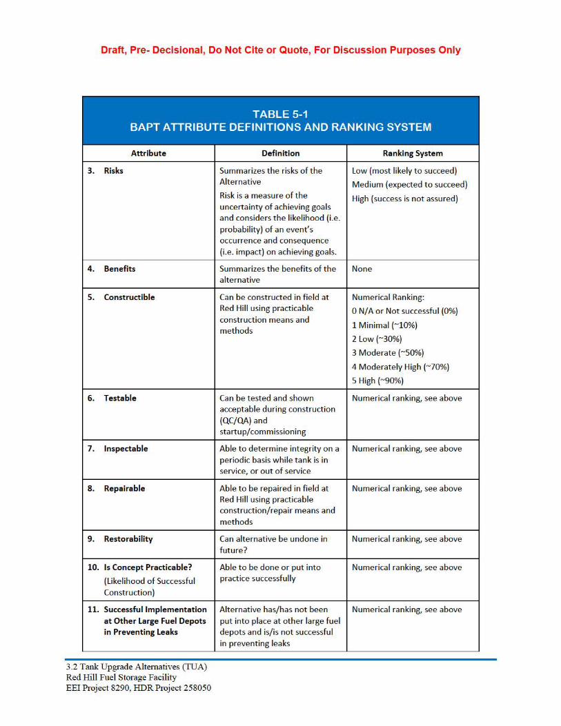
5.2 BAPT Attribute Definitions and Ranking System
Each BAPT is assessed for several attiibutes, with a ranking system applied to each atti·ibute to aid in evaluating each alternative relative to each other. Attributes and suggested ranking system are defined in the following table.
TABLE 5-1 BAPT ATTRIBUTE DEFINITIONS AND RANKING SYSTEM
Attribute Definition Ranking System
1. Primary Positive Attributes Summarizes the pros of t he alternat ive
N/A - subjective informat ion
2. Primary Negative Attributes
Summarizes the cons of t he alternative
N/A - subjective information
3.2 Tank Upgrade Altema.tives (TUA) Red Hill Fuel Storage Facility EEi Project 8290, HDR Project 258050
Draft, Pre- Decisional, Do Not Cite or Quote, For Discussion Purposes Only
TABLE 5-1 BAPT ATTRIBUTE DEFINITIONS AND RANKING SYSTEM
Attribute Definition Ranking System
3. Risks Summarizes the risks of the Alternative
Risk is a measure of t he uncertainty of achieving goals and considers the likel ihood (i.e . probability) of an event's occurrence and consequence (i.e. impact) on achieving goals.
Low (most likely to succeed)
Medium (expected to succeed)
High (success is not assured)
4. Benefits Summarizes the benefits of t he alternative
None
5. Constructible Can be constructed in fie ld at Red Hill using practicable construction means and methods
Numerical Ranking:
0 N/A o r Not successful (0%)
1 Minimal (~10%)
2 Low (~30%)
3 Moderate (~so%)
4 Moderately High (~70%)
5 High (~90%)
6. Testable Can be tested a nd shown acceptable during construction
(QC/QA) and startup/commissioning
Numerical ranking, see above
7. lnspectable Able to determine integrity o n a periodic basis while tank is in service, or out of service
Numerical ranking, see above
8. Repairable Able to be repaired in field at Red Hill using practicable construction/repair means a nd methods
Numerical ranking, see above
9. Restorability Can alternative be undone in future?
Numerical ranking, see above
10. Is Concept Practicable?
(Like lihood of Successful
Construction)
Able to be done or put into practice successfully
Numerical ranking, see above
11. Successful Implementation
at Other Large Fuel Depots in Preventing Leaks
Alternative has/has not been put into place at other large fuel depots a nd is/is not successful in prevent ing leaks
Numerical ranking, see above
3.2 Tank Upgrade Altema.tives (TUA) Red Hill Fuel Storage Facility EEi Project 8290, HDR Project 258050

Draft, Pre- Decisional, Do Not Cite or Quote, For Discussion Purposes Only
TABLE 5-1 BAPT ATTRIBUTE DEFINITIONS AND RANKING SYSTEM
Attribute Definition Ranking System
12. Applicability to the Red Hill Bulk Fuel St orage Facility
Alternative is relevant a nd can be applied to the Red Hill tanks.
Numerical ranking, se.e above
13. Reliability (level of confidence)
Ability of a system or component to perform its required fu nctions under stated conditions fo r a specified period of time
Numerical ranking, se.e above
14. Manufacturer's Technical Information Availa ble
Is published info rmation o n major components available from vendors
15. Ability to Obtain Vendor or Manufacturer Guarantee
Is t here a vendor or manufacture r of t he tank upgrade, and are they will ing to provide a guarantee that exceeds the normal one year const ruction warrantee
Yes, Partially, No
16. Depe nde ncy on Existing Tank Integrity
Identifies if a nd how t he alternative is dependent in the integrity of the existing tank to be successful
0 High Dependency (~90%)
1 Moderately High (~70%)
2 Moderate (~so%)
3 Low (~30%)
4 Minimal (~10%)
5 No Dependency (~90%)
17. Lower Dome Treatment Co nsiderations a nd Alternatives
18. Upper Dome Treat ment Co nsiderations a nd Alternatives
19. Testing a nd Commissioning Procedure s
20. Rationale for Testing and Commissioning Procedures
3.2 Tank Upgrade Alternatives (TUA) Red Hill Fuel Storage Facility EEi Project 8290, HDR Project 258050

Draft, Pre- Decisional, Do Not Cite or Quote, For Discussion Purposes Only
TABLE 5-1 BAPT ATTRIBUTE DEFINITIONS AND RANKING SYSTEM
Attribute Definition Ranking System
21. Ability to Repair Failures 0 No Ability (0%)
1 Minimal (~10%)
2 Low (~30%)
3 Moderate (~so%)
4 Moderately High (~70%)
5 High (~90%)
22. Service Life Limitations Identifies limitations of a 1 year technology to either survive to 5to 10 years the future, with appropriate expected normal and usual
10 to 20 years
repairs, or is limited by some 20 to 30 years
characteristic of the technology 40 years or greater
23. Provides Secondary Alternative provides/does not No - Does not provide secondary Containment provide secondary containment
of a release from the primary tank. A primary tank is t he wall of t he tank t hat provides primary containment, e.g. the wall of a single wall tank or t he inner wall of a double wall tank.
containment
Yes - Provides secondary containment
24. Impact on Storage Volume Alternative results in a reduction in tank storage volume.
Storage volume is based on t he physical volume of the container to contain liquid compared to existing and does not consider safe fill height, level alarm set point, o r overfill protection shutoff
25. Impact on ATG Identifies if t he technology has no impact on Automatic Tank Gauging systems, or if the technology complicates, o r prevents application of a DoD grade tank inventory system via an automatic tank gauging system
3.2 Tank Upgrade Alternatives (TUA) Red Hill Fuel Storage Facility EEi Project 8290, HDR Project 258050

Draft, Pre- Decisional, Do Not Cite or Quote, For Discussion Purposes Only
TABLE 5-1 BAPT ATTRIBUTE DEFINITIONS AND RANKING SYSTEM
Attribute Definition Ranking System
26. Impact on Tank Venting Identifies if t he present tank vent ing system needs to be modified, o r is it acceptable in fundame ntally same configu ration
27. Impact on Tank Nozzles Identifies degree of modification to the tank nozzles needed to support the new tank configu ration
28. Impact on Operating Identifies if t he curre nt means Requirements and of fill ing, emptying, or Procedures management of a static tank
condit ion is impacted by t he tank configuration
29. Impact on Maintenance Requirements and Practices
Identifies broad form tank maintenance requirements, and if different then general current requirements and practices
30. TIRM Requirements for Original Alternative Execution
Identifies level ofTIRM needed for inspection of existing tank steel lining, prior to application of upgrade technology
31. TIRM Requirements for Identifies level of maintenance
Future Integrity Inspections and inspection required to maintain the system A discussion ofpost construction operational and maintenance requirements that will ascertain tank integrity, and provide for the normal and usual repair and long term maintenance of the tank. Information on schedules of major events (frequency and duration}, and parametric (planning level) cost estimates to execute recommendations
will be provided.
3.2 Tank Upgrade Alternatives (TUA) Red Hill Fuel Storage Facility EEi Project 8290, HDR Project 258050

Draft, Pre- Decisional, Do Not Cite or Quote, For Discussion Purposes Only
TABLE 5-1 BAPT ATTRIBUTE DEFINITIONS AND RANKING SYSTEM
Attribute Definition Ranking System
32. Ability to Identify Release Location
Alternative provides/does not provide the capability to identify the location of a release from the tank, or to identify t he general area of a leak w ithin the envelope
0 No Abi lity (0%)
1 Minimal (~10%)
2 Low (~30%)
3 Moderate (~so%)
4 Moderately High (~70%)
S High (~90%)
33. Ability to Identify Release Quantity
Alternative provides/does not provide the capability to identify the quantity of a release to an acceptable degree of accuracy
0 No Abi lity (0%)
1 Minimal (~10%)
2 Low (~30%)
3 Moderate (~so%)
4 Moderately High (~70%)
S High (~90%)
34. Can release detection Does t he nature and 0 No Abi lity (0%) system be used to stop a configuration of the secondary 1 M inimal (~10%) primary envelope breach containment, o r other release
2 Low (~30%)from reaching the detection system inherently environment prevent a leak to the
environment
3 Moderate (~so%)
4 Moderately High (~70%)
S High (~90%)
35. Ability to Reduce
(Minimize) the Magnitude of a Release
Ability to restrict t he flow rate of a leak to minimize quant ity released so that appropriate response measures may be taken before quantity of release is considered catastrophic (such as permitting a tank draindown)
0 No Abi lity (0%)
1 M inimal (~10%)
2 Low (~30%)
3 Moderate (~so%)
4 Moderately High (~70%)
S High (~90%)
36. Associated Release Detection System
Type of leak detection generic concept, and rel iance on accuracy
37. Capabilities (Release detection)
38. In tank Release Detection Is it mandatory to have sensors System Required within the tank envelope in
order to determine if a leak occurs
3.2 Tank Upgrade Altema.tives (TUA) Red Hill Fuel Storage Facility EEi Project 8290, HDR Project 258050

Draft, Pre- Decisional, Do Not Cite or Quote, For Discussion Purposes Only
TABLE 5-1 BAPT ATTRIBUTE DEFINITIONS AND RANKING SYSTEM
Attribute Definition Ranking System
39. Release Detection Provided Outside Primary Enve lope
Are primary leak detection sensors outside of t he tank.
Yes - No
40. Release Detection System Testable
Physical a bility to simulate a leak, or remove sensor for testing of accuracy
41. Compatibility with Current Release Detection System
42. Compatibility with Current Tank Tightne ss Test s
Identifies if t he periodic (currently annually) tank tightness testing can be cont inued the same, or modified procedure, but attain similarly accurate results, or if alternative is such that Tightness Testing is no longer needed
43. Compatibility with existing ancillary equipment a nd if required, upgrades to implement the technology
Identifies issues associated with tank piping, Valving, sampling, manholes, and other physical/operational characteristics that may be impacted by upgrade configu ration
None-low-med-high
44. Commercially Ava ilable Products - Existing Tank Preparation and Repairs/ Const ruction
45. Commercially Ava ilable Products - Release Detection Conce pt
3.2 Tank Upgrade Alternatives (TUA) Red Hill Fuel Storage Facility EEi Project 8290, HDR Project 258050

Draft, Pre- Decisional, Do Not Cite or Quote, For Discussion Purposes Only
TABLE 5-1 BAPT ATTRIBUTE DEFINITIONS AND RANKING SYSTEM
Attribute Definition Ranking System
46. Tank Upgrade Construction Cost Estimate (Planning Level)
(not including release detection system or fiber optic communication system)
An execution cost estimate of one tank constructed as a part of a multiple tank repair contract (2-4 tanks per contract) inclusive of an engineer's estimate of
construction costs and associated government execution costs will be developed. This execution cost estimate will be based on normal and usua l planning level guidelines for major military projects, using parametric estimating techniques.
None
47. Construction Schedule An estimate of execution time for one tank upgrade, and combinations of tank upgrades inclusive of typical government contracting time requirements.
None
48. Consistency with Local A general statement attesting to Yes, No Policies and Resolution the alternative being consistent
with Applicable and Apropriate regulations as identified
5.3 Alternatives
The following are examples of detailed discussion on the alternatives that will be developed later. See Alt 2A for somew hat better developed example
3.2 Tank Upgrade Altema.tives (TUA) Red Hill Fuel Storage Facility EEi Project 8290, HDR Project 258050

Draft, Pre- Decisional, Do Not Cite or Quote, For Discussion Purposes Only
5.3.1 Alternative 1A - Restoration of Tank
5.3.1.1 General Description
Alternative IA is similar to the cunent approach to inspect and repair the tanks but with enhanced TIRM procedures established to assure the full integrity of the existing steel liner is investigated for long te1m life extension repairs. Tank repairs include repaiiing pitting, holes, and defective welds (inte1mittent cracks, lack of fusion, porosity, and slag inclusions) in the existing steel liner. Alternative IA also includes extensive repafrs to present existing single wall concrete encased piping from the tank to the first valve outside tank or replacing the entire piping with double wall constrnction.
Overall the inspection and repair is considered conventional constrnction, with the emphasis placed on thoroughness, with appropriate contractor Quality Control (QC) and government oversight and Quality Assurance program.
This alternative only includes recoating the lower dome with DoD approved polysulfide modified epoxy Novolac coating system.
The presumption in this AOC Section 3 is that the resultant single wall tank solution will result in the need for a qualified technology based in-situ "leak detection" system as outlined in AOC Section 4, Release Detection I Tank Tightness Testing.
5.3.1.2 Preparato1y Inspection and Repair ofExisting Tank Liner
5.3.1.3 Features ofAlternative IA Upgrades
5.3.1.4 Constrnction Logistics
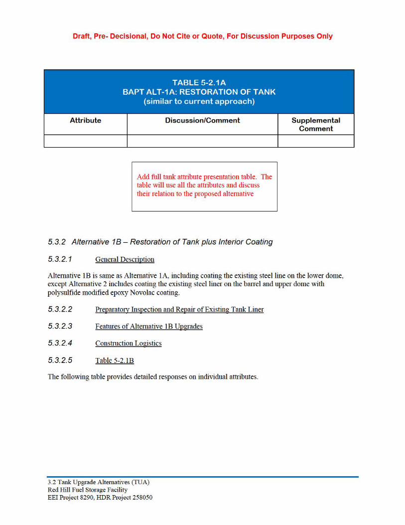
5.3.1.5 Table 5-2.IA
The following table provides detailed responses on individual attributes.
Attribute Discussion/Comment Supplemental Comment
3.2 Tank Upgrade Alternatives (TUA) Red Hill Fuel Storage Facility EEi Project 8290, HDR Project 258050
Draft, Pre- Decisional, Do Not Cite or Quote, For Discussion Purposes Only
Attribute Discussion/Comment Supplemental Comment
Add full tank attribute presentation table. The table will use all the attributes and discuss their relation to the proposed alternative
5.3.2 Alternative 18- Restoration of Tank plus Interior Coating
5.3.2.1 General Description
Alternative IB is same as Alternative IA, including coating the existing steel line on the lower dome, except Alternative 2 includes coating the existing steel liner on the bane! and upper dome with polysulfide modified epoxy Novolac coating.
5.3.2.2 Preparato1y Inspection and Repair ofExisting Tank Liner
5.3.2.3 Features ofAlternative IB Upgrades
5.3.2.4 Constrnction Logistics
5.3.2.5 Table 5-2. I B
The following table provides detailed responses on individual attributes.
3.2 Tank Upgrade Alternatives (TUA) Red Hill Fuel Storage Facility EEi Project 8290, HDR Project 258050

- - -
Draft, Pre- Decisional, Do Not Cite or Quote, For Discussion Purposes Only
Attribute Discussion/Comment Supplemental Comment
Note: Alt-lB is nearly identical to Alt-lA. Items in Alt-lB t hat diffe r from Alt-lA are indicated in bold italics.
Add full tank att1ibute presentation table
5.3.3 Alternative 1D - Remove Steel Liner, Install New Liner
5.3.3.1 General Description
5.3.3.2 Preparato1y Inspection and Repair ofExisting Tank Liner
5.3.3.3 Features ofAlternative ID Upgrades
5.3.3.4 Constrnction Logistics
5.3.3.5 Table 5-2.ID .. . .. - .. .. .. .. .. . TABLE 5-2.1 D
BAPT ALT-1 D: REMOVE STEEL LINER, INSTALL NEW LINER
Attribute Discussion/Comment Supplemental Comment
Add full tank attiibute presentation table
3.2 Tank Upgrade Altema.tives (TUA) Red Hill Fuel Storage Facility EEi Project 8290, HDR Project 258050

Draft, Pre- Decisional, Do Not Cite or Quote, For Discussion Purposes Only
5.3.4 Alternative 2A – Composite Tank (Double Wall) Carbon Steel
5.3.4.1 General Description
Alternative 2A – Composite Tank, consists of providing a 1/4 inch thick carbon steel liner inside the tank supported by structural steel angles welded to the existing steel liner. The new steel liner is the primary tank envelope and is separated from the existing steel liner by angles to create a 3-inch wide interstitial space for release detection. To resist fluid pressure from tank contents, the interstitial space is filled with self-leveling concrete or grout. The product side of the primary steel liner will be coated with a polysulfide modified epoxy Novolac in accordance with UFGS 09 97 13.15 “Low VOC Polysulfide Interior Coating of Welded Steel Petroleum Fuel Tanks”. The existing steel liner will not be coated.
General Description to include a discussion of 1) NOT filling the interstitial space with grout, 2) installation of a Cathodic protection system and 3) application of the design at other tank systems
3.2 Tank Upgrade Alternatives (TUA) Red Hill Fuel Storage Facility EEI Project 8290, HDR Project 258050

Draft, Pre- Decisional, Do Not Cite or Quote, For Discussion Purposes Only
5.3.4.2 Preparatory Inspection and Repair of Existing Tank Liner
Prior to the construction of the new tank liner, the existing steel shell must undergo an inspection and repair that will identify the integrity of the existing liner to serve as a secondary containment liner, and identify deficiencies needing repair. This also will serve to minimize the risk of a future breach permitting groundwater, if present, from entering the secondary containment.
The basic requirements for inspection of the existing liner were discussed above under Alternative 1A, and are based on the findings of AOC Section 2, Tank Inspection, Repair and Maintenance (TIRM).
3.2 Tank Upgrade Alternatives (TUA) Red Hill Fuel Storage Facility EEI Project 8290, HDR Project 258050

Draft, Pre- Decisional, Do Not Cite or Quote, For Discussion Purposes Only
Modifications to the base TIRM, to reflect the needs of this alternative include:
Some discussion and development of TIRM deviations/modifications
5.3.4.3 Features of Alternative 2A Upgrades
Specific features of the Alternative 2A Composite System include:
Six foot wide, 1/4 inch thick, 20-foot long carbon steel liner plates arranged vertically on the tank barrel.
Liner plates supported by 3 inch x 3 inch angles (L3x3x1/4) at 6’-0” on center, arranged vertically and welded to the existing steel liner, extending from the lower dome spring line to 2’-0” below the expansion joint between the barrel and upper dome. This compartmentalizes the interstitial space of the tank barrel into 52 vertical spaces for improved release detection and leak location.
The width of the liner plates and spacing of the angles at 6’-0” on center is based on the maximum width of the liner plate that can be moved through the existing isolation doors in the Upper Tunnel to Tanks 17, 18, 19, and 20. Slightly wider sheets could be used for Tanks 1 to 16; however, the sheets would still need to fit through the 8-foot diameter manhole of the tank. EEI recommends 6’-0” wide x 20’-0” long plates for all tanks.
Interstitial space filled with self-leveling concrete or non-shrink grout having a minimum compressive strength of 2,500 psi. To resist fluid pressure in the interstitial space from the concrete or grout without excessive bulging, the self-leveling concrete or grout must be placed in lifts not exceeding 5 feet and the liner plates need to be supported continuously with vertical
3.2 Tank Upgrade Alternatives (TUA) Red Hill Fuel Storage Facility EEI Project 8290, HDR Project 258050

Draft, Pre- Decisional, Do Not Cite or Quote, For Discussion Purposes Only
angles welded to the existing steel line at 3’-0” on center
Two vertical angles arranged in the shape of a tube will be provided in the interstitial space at the center of the liner plate to support the liner plate and form a drainage path for release detection. To prevent compartmentalizing the interstitial spaces into 3’-0” wide spaces the two support angles at the center of the liner plate which form a drainage tube will be welded to the existing liner with intermittent fillet welds and will have drainage holes so that liquid (fuel or water) in the interstitial space can drain into the drainage space to the release detection pipes.
3.2 Tank Upgrade Alternatives (TUA) Red Hill Fuel Storage Facility EEI Project 8290, HDR Project 258050

Draft, Pre- Decisional, Do Not Cite or Quote, For Discussion Purposes Only
The primary steel liner plates in the lower dome will be supported similar to the liner plates on the barrel except the support angles will be will extend radially from the center of the bottom of the dome up to the spring line.
Alternative 2A does not include lining the upper dome, due to the very high incremental cost compared to the increase in storage capacity of approximately 45,900 Bbl. (based on a 3inch wide interstitial space). The composite liner will terminate and be sealed approximately 2 feet below the expansion joint of the upper dome. The upper dome will be inspected and repaired only to prevent infiltration of ground water.
The Composite tank concept includes an integral release detection system as follows:
A horizontal drainage “tube” space will be provided in the interstitial space at mid-height and the bottom of the barrel. These horizontal “tube” spaces will be continuous around the tank and be compartmentalized into 13 zones each.
The vertical drainage tube in each of 52 interstitial spaces in the barrel will tie into the horizontal tube space at mid-height and the bottom of the barrel. As the horizontal tubes are compartmentalized to into 13 zones, four 6’-0” wide interstitial spaces are headered together per zone. This provides 13 zones on the lower half of the barrel and 13 zones in the upper half of the barrel (26 zones total).
3.2 Tank Upgrade Alternatives (TUA) Red Hill Fuel Storage Facility EEI Project 8290, HDR Project 258050

Draft, Pre- Decisional, Do Not Cite or Quote, For Discussion Purposes Only
Release detection piping will be provided and connect to the 13 compartments in each horizontal tube space. Thus, there will be 26 leak release detection pipes, each pipe serving 4 interstitial spaces of the barrel.
Piping will be 1-1/2” diameter, extra strong pipe to reduce possibility of pipe blockage and to increase service life. All release detection piping will be fully welded. No threaded fittings will be permitted. The 13 release detection pipes servicing the upper half of the barrel will be routed through an 18-inch diameter penetration in the lower dome to the Lower Tunnel. The 13 release detection pipes servicing the lower half of the barrel will be through second 18-inch diameter penetration in the lower dome to the Lower Tunnel. Drilling or coring of the concrete between the existing lower dome and the Lower Tunnel will be required in order to provide a path for the release detection piping.
In addition to the 26 zones for the tank barrel, one zone will be provided for the entire lower dome. The release detection piping for the lower dome will be routed from a sump below the center of the lower dome floor to the Lower Tunnel.
The release detection pipes from the 26 zones of the barrel and the one zone of the lower dome will be grouped into a manifold in the Lower Tunnel.
If a leak is detected in the barrel, the search for the leak can be narrowed to a 24’-0” wide area of the barrel consisting of 4 interstitial spaces. The release detection system also can be used for injection of a detectable gas in the interstitial space to locate the leak. As the entire lower dome is one zone for release detection, a leak detected in the lower dome would involve inspecting the entire lower dome to locate and repair the leak.
3.2 Tank Upgrade Alternatives (TUA) Red Hill Fuel Storage Facility EEI Project 8290, HDR Project 258050

Draft, Pre- Decisional, Do Not Cite or Quote, For Discussion Purposes Only
5.3.4.4 Constrnction Logistics
5.3.4.5 Table 5-2.2A
The following table provides detailed responses on individual attributes.
Attribute Discussion/Comment Supplemental Comment
Note t hat numerous alternative industrial
Summary Description • Creates double wall, secondarily contained tank.
• 1/4 inch thick carbon steel liner inside the tank grade coatings could besupported by structural steel angles welded to considered, but all mustthe existing steel liner. Steel liner is separated pass the criteria offrom the existing steel liner by angles to create a surviving military3 inch wide interstit ial space for release additives in fuel. Any detection. Steel liner becomes primary tank alternative would notenvelope. necessari ly present a
• Interstitial space filled with concrete o r grout to diffe re nt solution, only a resist flu id pressure on steel liner from tank permutation of this contents. Alternative, t hus not
• Product s ide of the steel liner coated with considered separately at polysulfide modified epoxy Novolac in this time. accordance with UFGS 09 9713.15 "Low VOC Polysulfide Interior Coating of Welded Steel Petroleum Fuel Tanks".
• Zoned interstitial space release detection concept provides dynamic full t ime re lease detection with alarming to central location.
• Existing steel liner is inspected a nd repaired and becomes secondary containment.
• Only lower dome and barrel receive composite liner.
• This alternative includes replacing t he existing single wall concrete encased piping from the tank to the first valve outside tank with double wall construction.
3.2 Tank Upgrade Altema.tives (TUA) Red Hill Fuel Storage Facility EEi Project 8290, HDR Project 258050

Draft, Pre- Decisional, Do Not Cite or Quote, For Discussion Purposes Only
Attribute Discussion/Comment Supplemental Comment
Graphic
;{_~__, ______,. CONTAINER VOLUME
"""' MAX SAFE ALL
1. Primary Positive • Provides secondary containment. Attributes • Provides release detection. No special
technology required for release detection other t han sensors in re lease detection piping/chamber in lower tunnel.
2. Primary Negative • Higher cost than restorat ion of exist ing tank Attributes (Alternatives lA, lB, and lC).
• Reduced storage volume (upper dome not used).
3. Risks • Risk of a release to the environment is very low as t he tank would have secondary conta inment .
• Risk of fa ilure of construct ion resulting in an unacceptable end product must be addressed by appropriate design, contractor quality control, and government quality assurance systems a nd controls in place.
3.2 Tank Upgrade Altema.tives (TUA) Red Hill Fuel Storage Facility EEi Project 8290, HDR Project 258050

Draft, Pre- Decisional, Do Not Cite or Quote, For Discussion Purposes Only
Attribute Discussion/Comment Supplemental Comment
4. Benefits • Provides secondary containment t hat is testable for integrity.
• Able to detect, locate (within 14 o r more zones), and contain leaks in existing steel liner and primary steel liner (primary tank envelope).
• Detectable volume of liquid re leased is very small, as liquid conveyed to collection point below tank by release detection system within interstit ial space.
5. Feasible • Construct ion will follow fa irly standard industry tank and structural steel e rection techniques, followed by coating application. Greatest challenge for construction is based on logistics and restrictions due to working at Red Hill and inside t he fuel storage facility a nd inside the tank.
6. Testable • All aspects of construction a re fully inspectable during the construction process and testable fo r integrity as a part of fi nal testing and commissioning.
7. lnspectable • Future inspection for integrity no different t han current integrity inspections of existing tanks (l iner plate scanning, weld scanning) following industry pract ices adapted to Red Hill conditions. Updated TIRM to be utilized.
• Integrity testing of interstitial space a nd release detection system provided by design.
3.2 Tank Upgrade Altema.tives (TUA) Red Hill Fuel Storage Facility EEi Project 8290, HDR Project 258050
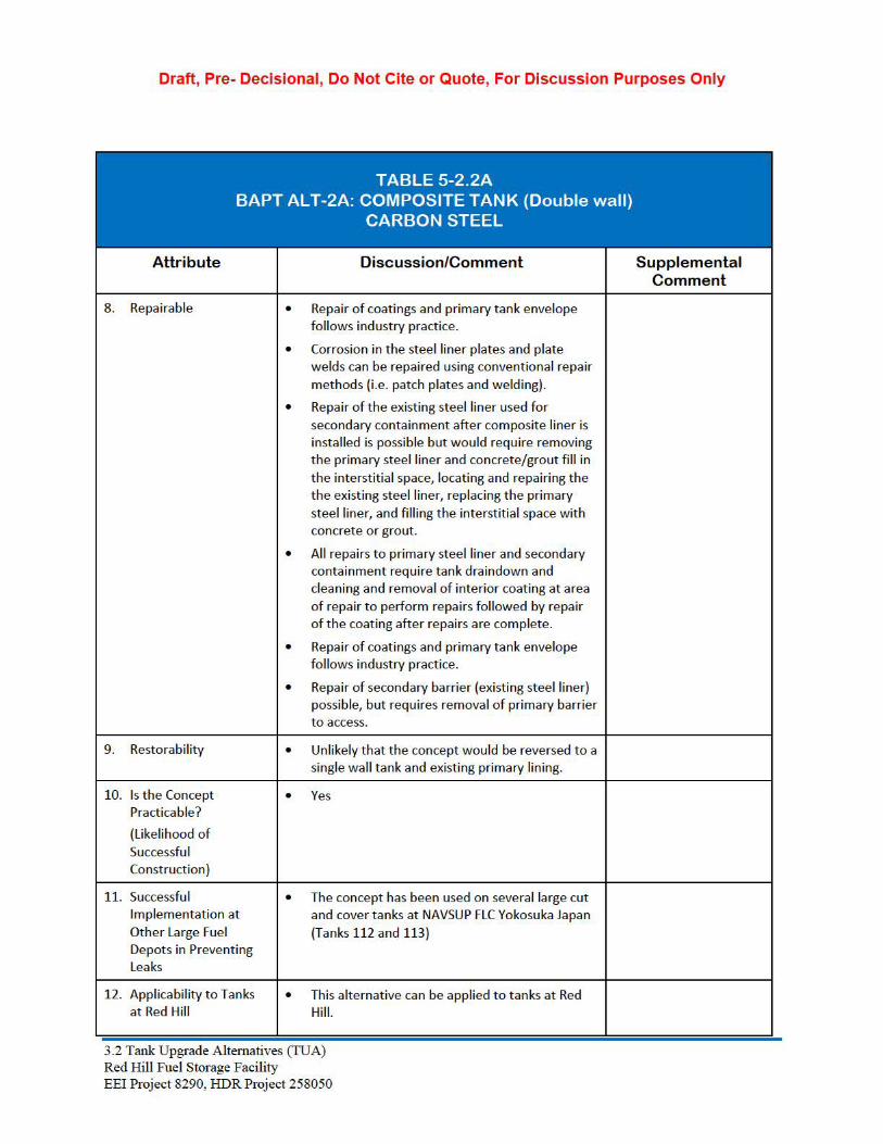
Draft, Pre- Decisional, Do Not Cite or Quote, For Discussion Purposes Only
Attribute Discussion/Comment Supplemental Comment
8. Repairable • Repair of coatings and primary tank envelope follows industry practice.
• Corrosion in the steel liner plates and plate welds can be repaired using convent ional repair methods (i.e . patch plates a nd welding).
• Repair of the existing steel liner used fo r secondary containment after composite liner is installed is possible but would require removing the primary steel liner and concrete/grout fill in the interstitial space, locating and repairing the the existing steel liner, replacing the primary steel liner, and fill ing the interstitial space with concrete or grout.
• All repairs to primary steel liner and secondary containment require tank draindown and cleaning and removal of interior coating at area of repair to perform repairs followed by repair of the coating after repairs are complete.
• Repair of coatings and primary tank envelope follows industry practice.
• Repair of secondary barrier (existing steel liner) possible, but requires removal of primary barrie r to access.
9. Restorability • Unlike ly t hat t he concept would be reversed to a single wall tank and existing primary lining.
10. Is t he Concept • Yes Practicable?
(Likelihood of Successful Construction)
11. Successful • The concept has been used on several large cut Implementation at and cover tanks at NAVSUP FLC Yokosuka Japan Other Large Fuel (Tanks 112 and 113) Depots in Preventing Leaks
12. Applicability to Tanks • This alternative can be applied to tanks at Red at Red Hill Hill.
3.2 Tank Upgrade Altema.tives (TUA) Red Hill Fuel Storage Facility EEi Project 8290, HDR Project 258050

Draft, Pre- Decisional, Do Not Cite or Quote, For Discussion Purposes Only
Attribute Discussion/Comment Supplemental Comment
13. Reliability • Performance is dependent on inspection (i.e. (confidence) ability to find and locate defects), welder
qualificat ions, and nondestructive examination of completed repairs. Technology of repairs not quest ioned.
• Does not rely upon inferent ial release detection systems requiring longer test ing cycles, very special sensor technology, and rigorous computer based statistical analysis of measurement to determine if a release has occurred.
• Not applicable. All repairs would be based on acceptable engineering standards and applicable
14. Manufacturer's Technical Information
indust rial guidelines.
15. Ability to Obtain • No, This is an engineered solution constructed Vendor o r by a selected contractor. There is no vendor or Manufacturer manufacturer per se. Guarantee
16. Dependency on Similar to current Existing Tank Integrity
• Exist ing steel liner on tank barrel and lower integrity management
integrity must be fully invest igated and dome becomes secondary containment, t hus
approach (with
deficiencies repaired. enhancements as noted in TIRM)
17. Lower Dome • Exist ing steel liner of lower dome would be Treatment inspected and repaired same as the steel liner Considerations and on t he tank barrel using conventional repair Alternatives methods (i.e. patch plates and welding).
• Lower dome would receive steel liner and concrete or grout filled interstitial space same as the tank barrel and release detection.
18. Upper Dome • Upper dome will be inspected and repaired to Treatment prevent infiltration of ground water. Considerations and • Upper dome surface will be coated same as tank Alternatives primary envelope.
• Upper dome does not receive composite liner .
3.2 Tank Upgrade Altema.tives (TUA) Red Hill Fuel Storage Facility EEi Project 8290, HDR Project 258050

Draft, Pre- Decisional, Do Not Cite or Quote, For Discussion Purposes Only
Attribute Discussion/Comment
19. Test ing a nd • Perform 100% scanning of t he existing steel liner Commissioning and welds of barrel and lower dome of the Procedures existing tank.
• Perform nondestructive examination of repairs to exist ing steel liner.
• Perform nondestructive examination of welds of primary steel liner.
• Perform in process quality control of primary tank envelope following industry standards, modified for Red Hill construction (based on API tank construction and industry practice).
• Perform integrity test ing of interstitial space and release detection collection piping prior to introducing fuel into t he tank.
• Perform tank integrity leak testing with fuel as a part of return to service commissioning.
20. Rationale for Testing • Industry standard quality control during and Commissioning construction, and government quality assurance Procedures programs can be applied to assure a liquid t ight
container is constructed.
• Integrity testing of interstit ial space a nd release detection system is crucial to initially placing the tank in service.
• Integrity testing with fue l provides final check of hydraulic integrity of primary steel liner. Presence of fue l in release detection pipes would indicate a breach in t he primary steel liner.
Supplemental Comment
Leak testing would be equivalent to, or same as current a nnual tank t ightness testing.
Note t hat a hydrostatic test with water is not required as it is a structural test, more than a leak test. Based on t he tank upgrades as described, a structural test is not warranted.
3.2 Tank Upgrade Altema.tives (TUA) Red Hill Fuel Storage Facility EEi Project 8290, HDR Project 258050

Draft, Pre- Decisional, Do Not Cite or Quote, For Discussion Purposes Only
Attribute Discussion/Comment Supplemental Comment
21. Ability to Repair • Corrosion in the steel liner plates and plate Failures welds can be repaired using convent ional repair
methods (i.e. patch plates and welding).
• Repair of leaks in existing steel liner used for secondary containment after composite liner is installed is possible but would require removing the primary steel liner and concrete/grout fill in the interstitial space, locating and repairing the leak in the existing steel liner, replacing t he primary steel liner, and fill ing t he interstitial space w it h concrete o r grout.
• All repairs to primary steel liner and secondary containment require tank drain down and cleaning and removal of interior coating at area of repair to perform repairs followed by repair of the coating after repairs are complete.
22. Service Life Limitations • Service life of existing steel liner and primary steel liner is dependent on inspection and repairs performed at t ime of base-line repairs.
• The government to determine design service life. For example if a 40 year life is selected, corrosion rates, minimum remaining t hickness below which would require repair, and subsequent repairs to existing steel liner would be based on t his. This 40 year life of the existing steel liner could be extended by repairing more deficiencies, w ith t he result of extending the life perhaps another 70 years.
• Existing steel liner on tank barrel and lower23. Provides Secondary dome becomes secondary containment. Containment
3.2 Tank Upgrade Altema.tives (TUA) Red Hill Fuel Storage Facility EEi Project 8290, HDR Project 258050

Draft, Pre- Decisional, Do Not Cite or Quote, For Discussion Purposes Only
Attribute Discussion/Comment
24. Impact on Storage • Alternative provides for fuel storage in lower Volume dome and tank barrel up to 2 feet below t he
expansion joint at t he top of t he barrel, and no fuel storage in upper dome.
• The interstitial space (3-inches all around) a lso results in reduction in storage volume.
• Tank container volume: 234,846 Bbl
• With a 3 inch interstitial space and not using the upper dome space, there is a reduction in storage volume compared to Alts lA, lB, and lC:
Ta nks 1to4: 50,289 Bbl reduction per tank
Ta nks 5 to 20: 67,075 Bbl reduction per tank
• Storage volume at level alarm set points:
HLA (90%): 211,361 Bbl
HHLA (95%): 223,104 Bbl
• Storage volume at max safe fill (90%): 211,361 Bbl
25. Impact on ATG • None, t he same, or similar system can be used.
• New tank calibration (strapping) required
26. Impact on Tank Vent ing • None
27. Impact on Tank Nozzles • Modifications required to accommodate new tank composite liner, and to respond to existing integrity concerns
28. Impact on Operating • Reduced volumes would need to be addressed Requirements and in Standard Operating Procedures Procedures
Supplemental Comment
• Storage volume is based on t he physical volume of the container to contain liquid compared to existing and does not consider safe fill height, level alarm set point, or overfill protection shutoff.
• Level alarm set points are per UFC 3460-01.
• HLA: High Level Alarm
• HHLA: High-High Level Alarm
3.2 Tank Upgrade Altema.tives (TUA) Red Hill Fuel Storage Facility EEi Project 8290, HDR Project 258050

Draft, Pre- Decisional, Do Not Cite or Quote, For Discussion Purposes Only
Attribute Discussion/Comment
29. Impact on • Perform periodic cleaning and inspection. The Maintenance goal is a minimum 20 year inspection cycle. Requirements and • Repair of defects in steel liner (primary tank Procedures envelope) will require removal of interior
coating followed by repair of the coating after steel liner repairs are complete.
• Recoating of the steel liner (primary tank envelope) can be expected on a 30-40 year basis, plus periodic maintenance at out of service inspections.
30. TIRM Requirements for • To be developed Original Alternative Execution
31. TIRM Requirements for • To be developed Future Integrity Inspections
32. Ability to Identify • A leak can be isolated to area of the shell Release Location covered by the leak detection zone
33. Ability to Identify • The nature of t he secondary containment Release Quant ity interstit ial system is such that the leak is
captured and stopped before entering t he environment . Also, the leak detection interstit ial zone can be drained into suitable container in the lower tunnel area, and measured
34. Ability to Stop a • Inherent within system design Release from t he Tank
35. Ability to Reduce • Very good (Minimize) the Magnitude of a Release
Supplemental Comment
3.2 Tank Upgrade Altema.tives (TUA) Red Hill Fuel Storage Facility EEi Project 8290, HDR Project 258050

Draft, Pre- Decisional, Do Not Cite or Quote, For Discussion Purposes Only
Attribute Discussion/Comment
36. Associated Release • Release detection zones in t he barre l (14 to 26 Detection System zones) and lower dome (1 zone), and piped by
gravity to sensor racks in lower tunnel. Provides dynamic full t ime re lease detection.
• Very small leaks can be detected with conventional pressure rated sensors.
• Easy to test re lease detection sensors .
37. Capabilit ies (Release • Leaks ident ified outside of primary tank Detection) envelope, via interstit ial space.
• Able to detect, locate, and contain leaks in existing steel liner and primary steel liner (primary tank envelope). Leaks detected before they enter t he environment.
• Release detection zoned by shell area (26 zones) and lower dome (1 zone), and piped by gravity to sensor chamber in lower tunnel. Provides dynamic full t ime re lease detection with alarming to central location.
38. In tank Release • no Detection System Required
39. Release Detection • yes Provided Outside Primary Envelope
40. Release Detection • Within limitations, yes, depending on design System Testable solutions and construction considerations
41. Compatibility with • Compatible . Current Release Detection System
42. Compatibility with • Compatible. No impact to current tank t ightness Current Tank Tightness testing. Tests • Frequency of testing is policy issue, not
engineering issue.
Supplemental Comment
Integrity testing of release detection system (entire secondary containment zone) possible if designed for this need.
• Tubes cast in interstit ial space in barrel to improve connectivity of breach location to zone collection headers.
• Tell-tales from barre l zones conveyed through exposed pipe inside tank in lower dome.
Note t hat with contemplated interstitial secondary containment, tank t ight ness testing no longer required as currently conducted.
3.2 Tank Upgrade Altema.tives (TUA) Red Hill Fuel Storage Facility EEi Project 8290, HDR Project 258050

Draft, Pre- Decisional, Do Not Cite or Quote, For Discussion Purposes Only
Attribute Discussion/Comment Supplemental Comment
43. Compatibility w ith • Compatible. No impact to existing ancillary existing ancillary equipment. equipment and if • However, it is anticipated t hat a new ATG required, upgrades to system would be implemented at time of implement t he repairs. technology
• Integrity testing for repairs is specialized, but44. Commercially Avai lable Products - Existing commercially available. Tank repair materials
are common to any fuel storage tank repair. Tank Preparation and Repairs/Construction • Construction of steel liner is specialized in Red
Hill, but well w ithin the capabilit ies of commercial/industrial application.
• Coating systems are readily available, and DoD had conducted extensive experiments to prove out suitability for DoD fuels w ith additives (as compared to un-additized commercial fuels).
45. Commercially Avai lable • Interstitial space for release detection is Products - Release common. Detection Concept • Permits use of off the shelf industrial release
detection sensor outside the tank (will be in lower tunnel), numerous technologies available.
• To be determined 46. Tank Upgrade Construction Cost Estimate (Planning Level)
(not including release detection system or fiber optic communication system)
If aggressive means taken, and multiple shifts Bid package must47. Construction Schedule permitted, a two year schedule is possible. Under anticipate full range of normal military construction approach, more likely a potential repairs to four year schedule expected. minimize change o rder
delays.
3.2 Tank Upgrade Altema.tives (TUA) Red Hill Fuel Storage Facility EEi Project 8290, HDR Project 258050

Draft, Pre- Decisional, Do Not Cite or Quote, For Discussion Purposes Only
Attribute Discussion/Comment Supplemental Comment
A general statement attesting to the alternative Yes, No48. Consistency with Local being consistent with Applicable and ApropriatePolicies and Resolution regulations as identified
5.3.5 Alternative 28- Composite Tank (Double Wall) Duplex Stainless Steel
5.3.5.1 General Description
Alternative 2B is same as Alternative 2A except uses duplex stainless steel instead of carbon steel liner.
General Description to include a discussion of I) NOT filling the interstitial space with grout adand 2) installation ofa Cathodic protection system and 3) application of the design at other tank systems
5.3.5.2 Preparato1y Inspection and Repair ofExisting Tank Liner
5.3.5.3 Features ofAlternative 2B Upgrades
5.3.5.4 Constrnction Logistics
5.3.5.5 Table 5-2.2B
The following table provides detailed responses on individual attributes.
3.2 Tank Upgrade Altema.tives (TUA) Red Hill Fuel Storage Facility EEi Project 8290, HDR Project 258050

Draft, Pre- Decisional, Do Not Cite or Quote, For Discussion Purposes Only
Attribute Discussion/Comment Supplemental Comment
Note: Alt-2B is nearly identical to Alt-2A. Items in Alt-2B t hat d iffer from Alt-2A are ind icated in bold ital ics.
Add full tank attribute presentation table
5.3.6 Alternative 3A - Tank within a Tank (Carbon Steel)
5.3.6.1 General Description
Alternative 3A involves constrncting a carbon steel tank within the existing tank. The tank will be 90' -0" diameter, 150'-0" shell height. The smaller diameter of the new tank provides a 5 '-0" wide annular space around the tank that allows inspection of the exterior of the tank shell and the steel liner on the banel and upper dome of the existing tank. The new tank will be designed in accordance with the applicable sections ofAPI 650. The tank will be braced laterally with struts to the existing tank to resist rocking from seismic ground motions.
The existing steel liner on tank banel and lower dome is inspected and repaired and becomes secondaiy containment.
5.3.6.2 Preparato1y Inspection and Repair ofExisting Tank Liner
5.3.6.3 Features ofAlternative ID Upgrades
5.3.6.4 Construction Logistics
5.3.6.5 Table 5-2.3A
The following table provides detailed responses on individual attr·ibutes.
3.2 Tank Upgrade Altema.tives (TUA) Red Hill Fuel Storage Facility EEi Project 8290, HDR Project 258050

Draft, Pre- Decisional, Do Not Cite or Quote, For Discussion Purposes Only
Attribute Discussion/Comment
•
Supplemental Comment
Add full tank att1ibute presentation table
3.2 Tank Upgrade Altema.tives (TUA) Red Hill Fuel Storage Facility EEi Project 8290, HDR Project 258050

Draft, Pre- Decisional, Do Not Cite or Quote, For Discussion Purposes Only
5.4 BAPT Tank Upgrade Decision Matrix
Attribute
Description
1. Primary Positive Attributes
2. Primary Negative Attributes
3. Risks
4. Benefits
5. Co nstructible
6. Testable
7. lnspectable
8. Repairable
9. Resto rability
10. Is Conce pt Practicable? (Likelihood of Successful Co nstruction)
TABLE 5-3 TANK UPGRADE ALTERNATIVES - BAPT DECISION MATRIX
1A
Restoration of Tank
Alternative
18 10 2A 2 8
Restoration of Tank Remove Existing Composite Tank Composite Tank plus Interior Coating Steel Liner, Install (Double Wall} (Double Wall}
New Steel Liner Carbon Steel Duplex Stainless Steel
3A
Tank within a Tank (Carbon Steel}
3 .0 Tank Upgrade Altemat ives (TUA) Page 39 Red Hill Fuel Storage Facility SOW Outline EEi Project 8290, HDR Project 258050 September 2016

Draft, Pre- Decisional, Do Not Cite or Quote, For Discussion Purposes Only
TABLE 5-3 TANK UPGRADE ALTERNATIVES - BAPT DECISION MATRIX
Attr ibute Alternative
1A 18 10 2A 28 3A
Description Restoration of Tank Restoration of Tank plus Interior Coating
Remove Existing Steel Liner, Install New Steel Liner
Composite Tank (Double Wall) Carbon Steel
Composite Tank (Double Wall) Duplex Stainless Steel
Tank within a Tank (Carbon Steel)
11. Successful Implementation at Othe r Large Fuel Depots in Preventing Leaks
12. Applicability to the Red Hill Bulk Fuel Storage Facility
13. Reliability
14. Manufacturer's Technical Information
15. Ability to Obtain Vendor or Manufacturer Guara ntee
16. Depe nde ncy on Existing Tank Integrity
3 .0 Tank Upgrade Altemat ives (TUA) Page40 Red Hill Fuel Storage Facility SOW Outline EEi Project 8290, HDR Project 258050 September 2016
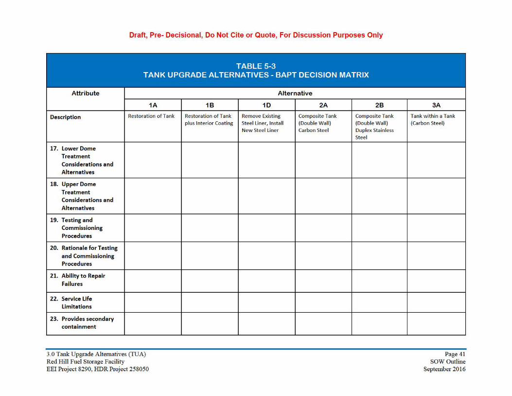
Draft, Pre- Decisional, Do Not Cite or Quote, For Discussion Purposes Only
Attribute
Description
17. Lower Dome Treatment Co nsiderations a nd Alternatives
18. Upper Dome Treatment Co nsiderations a nd Alternatives
19. Testing a nd Commissioning Procedures
20. Rationale for Testing and Commissioning Procedures
21. Ability to Repair Failures
22. Se rvice Life Limitations
23. Provides secondary containment
TABLE 5-3 TANK UPGRADE ALTERNATIVES - BAPT DECISION MATRIX
1A
Restoration of Tank
Alternative
18 10 2A 28
Restoration of Tank Remove Existing Composite Tank Composite Tank plus Interior Coating Steel Liner, Install (Double Wall) (Double Wall)
New Steel Liner Carbon Steel Duplex Stainless Steel
3A
Tank within a Tank (Carbon Steel)
3 .0 Tank Upgrade Altemat ives (TUA) Page41 Red Hill Fuel Storage Facility SOW Outline EEi Project 8290, HDR Project 258050 September 2016

Draft, Pre- Decisional, Do Not Cite or Quote, For Discussion Purposes Only
TABLE 5-3 TANK UPGRADE ALTERNATIVES - BAPT DECISION MATRIX
Attribute Alternative
1A 18 10 2A 28 3A
Description Restoration of Tank Restoration of Tank plus Interior Coating
Remove Exist ing Steel Liner, Install New Steel Liner
Composite Tank (Double Wall) Carbon Steel
Composite Tank (Double Wall) Duplex Stainless Steel
Tank within a Tank (Carbon Steel)
24. Impact on Storage Volume
25. Impact on ATG
26. Impact on Tank Venting
27. Impact on Tank Nozzles
28. Impact on Operating Requirements and Procedures
29. Impact on Maintenance Requirements and Procedures
30. TIRM Requirements for Original
Alternative Execution
31. TIRM Requirements for Future Integrity Inspections
3 .0 Tank Upgrade Altemat ives (TUA) Page42 Red Hill Fuel Storage Facility SOW Outline EEi Project 8290, HD R Project 258050 September 2016

Draft, Pre- Decisional, Do Not Cite or Quote, For Discussion Purposes Only
Attribute
Description
32. Ability to Identify Release Location
33. Ability to Identify Release Quantity
34. Ability to Stop a Release from t he Tank
35. Ability to Reduce (Minimize) the Magnitude of a Release
36. Associated Release Detection System
37. Capabilities (Release detection)
38. In tank Release Detection System Required
TABLE 5-3 TANK UPGRADE ALTERNATIVES - BAPT DECISION MATRIX
1A
Restoration of Tank
Alternative
18 10 2A 28
Restoration of Tank Remove Exist ing Composite Tank Composite Tank plus Interior Coating Steel Liner, Install (Double Wall) (Double Wall)
New Steel Liner Carbon Steel Duplex Stainless Steel
3A
Tank within a Tank (Carbon Steel)
3 .0 Tank Upgrade Altemat ives (TUA) Page43 Red Hill Fuel Storage Facility SOW Outline EEi Project 8290, HDR Project 258050 September 2016

Draft, Pre- Decisional, Do Not Cite or Quote, For Discussion Purposes Only
Attribute
Description
39. Release Detection Provided Outside Primary Envelope
40. Release Detection System Testable
41. Compatibility with Current Release Detection System
42. Compatibility with Current Tank Tightness Tests
43. Compatibility with existing ancillary equipment and if required, upgrades to implement the technology
44. Commercially Available Products Existing Tank Preparation and Repairs/Construction
TABLE 5-3 TANK UPGRADE ALTERNATIVES - BAPT DECISION MATRIX
1A
Restoration of Tank
Alternative
18 10 2A 28
Restoration of Tank Remove Existing Composite Tank Composite Tank plus Interior Coating Steel Liner, Install (Double Wall) (Double Wall)
New Steel Liner Carbon Steel Duplex Stainless Steel
3A
Tank within a Tank (Carbon Steel)
3 .0 Tank Upgrade Altemat ives (TUA) Page44 Red Hill Fuel Storage Facility SOW Outline EEi Project 8290, HDR Project 258050 September 2016

Draft, Pre- Decisional, Do Not Cite or Quote, For Discussion Purposes Only
TABLE 5-3 TANK UPGRADE ALTERNATIVES - BAPT DECISION MATRIX
Attribute Alternative
1A 18 10 2A 28 3A
Description Restoration of Tank Restoration of Tank plus Interior Coating
Remove Existing Steel Liner, Install New Steel Liner
Composite Tank (Double Wall) Carbon Steel
Composite Tank (Double Wall) Duplex Stainless Steel
Tank within a Tank (Carbon Steel)
45. Commercially Ava ilable Products -Release Detection Co ncept
46. Tank Upgrade Co nstruction Cost Estimate (Planning Level)
(not including release detection system or fiber optic communication system)
The following cost occurs during the first group of tank upgrades but the infrastructure is used for al l tanks:
Pole Line Electrical Power
Fi ber Optics (Data Transmission) for Release Detection on single wa ll tanks (Alts lA, l B, and l C)
47. Co nstruction Schedule
48. Co nsistency with Loca l Policies and Resolution
3 .0 Tank Up grade Altemat ives (TUA) Page45 Red Hill Fuel Storage Facility SOW Outline EEi Project 8290, HDR Project 258050 September 2016

Draft, Pre- Decisional, Do Not Cite or Quote, For Discussion Purposes Only
3.0 Tank Upgrade Alternatives (TUA) Page 46 Red Hill Fuel Storage Facility SOW Outline EEI Project 8290, HDR Project 258050 September 2016

Draft, Pre- Decisional, Do Not Cite or Quote, For Discussion Purposes Only
6.0 CONSTRUCTION EXECUTION ISSUES
6.1 Staging and Material Handling
6.1.1 Contractor Yard and Laydown
6.1.2 Tunnel Access to Tanks
6.2 Temporary Electrical Power
6.2.1 Existing Electrical Power at Red Hill
6.2.2 Temporary Power Supply
6.2.2.1 Temporary Overhead Line Alternative
6.2.2.2 Diesel Engines for Temporary Power
6.2.3 Temporary Tank Repair Electrical System
6.3 Data Communication – Fiber Optics
6.3.1 Existing Conditions
6.3.2 Need for New Fiber Optic Communications
6.4 Tank Access Shaft
6.4.1 Access for Power and Ventilation to Tank
6.5 Tank Staging Concepts for Work
6.5.1 Existing-Center Column Booms
6.5.2 Erect conventional Staging
6.5.3 Erect Trolley and Multiple Platforms around Perimeter
6.6 Tank Ventilation and Dehumidification
6.6.1 Welding Ventilation Requirements
6.6.2 Coating Ventilation and Dehumidification Requirements
3.0 Tank Upgrade Alternatives (TUA) Page 47 Red Hill Fuel Storage Facility Draft SOW Outline EEI Project 8290, HDR Project 258050 September 2016
Draft, Pre- Decisional, Do Not Cite or Quote, For Discussion Purposes Only
6.7 Construction Schedule
The Construction Schedule will be provided
3.0 Tank Upgrade Alternatives (TUA) Page 48 Red Hill Fuel Storage Facility Draft SOW Outline EEI Project 8290, HDR Project 258050 September 2016

Draft, Pre- Decisional, Do Not Cite or Quote, For Discussion Purposes Only
7.0 RELATED AOC INITIATIVES
7.1 Tank Inspection Repair and Maintenance (TIRM)
AOC Section 2.0 discusses TIRM
7.2 Release Detection / Tank Tightness Testing
AOC Section 4.0 addresses this
7.3 Corrosion and Metal Fatigue Practices Report
AOC Section 5.0 addresses this
3.0 Tank Upgrade Alternatives (TUA) Page 49 Red Hill Fuel Storage Facility Draft SOW Outline EEI Project 8290, HDR Project 258050 September 2016

Draft, Pre- Decisional, Do Not Cite or Quote, For Discussion Purposes Only
8.0 COST ESTIMATES
8.1 Cost Estimate Summaries
3.0 Tank Upgrade Alternatives (TUA) Page 50 Red Hill Fuel Storage Facility Draft SOW Outline EEI Project 8290, HDR Project 258050 September 2016
Draft, Pre- Decisional, Do Not Cite or Quote, For Discussion Purposes Only
9.0 DEFINITIONS
The following terms are used in this report. The definitions are from 40 CFR 280 Final Rule.
Existing Tank System: A tank system used to contain an accumulation of regulated substances or for which installation has commenced on or before December 22, 1988.
New Tank System: A tank system that will be used to contain an accumulation of regulated substances and for which installation has commenced after December 22, 1988.
Release: Any spilling, leaking, emitting, discharging, escaping, leaching or disposing from an UST into groundwater, surface water or subsurface soils.
Release Detection: Determining whether a release of a regulated substance has occurred from the UST system into the environment or a leak has occurred into the interstitial space between the UST system and its secondary barrier or secondary containment around it.
Secondary Containment or Secondarily Contained: A release prevention and release detection system for a tank or piping. This system has an inner and outer barrier with an interstitial space that is monitored for leaks. This term includes containment sumps when used for interstitial monitoring of piping.
Underground Storage Tank or UST: Any one or combination of tanks (including underground pipes connected thereto) that is used to contain an accumulation of regulated substances, and the volume of which (including the volume of underground pipes connected thereto) is 10 percent or more beneath the surface of the ground. This term does not include: Storage tanks situated in an underground area (such as a basement, cellar, mine working, drift, shaft, or tunnel) if the storage tank is situated upon or above the surface of the floor.
Additional Definitions
Primary Tank: The wall of the tank that provides primary containment, e.g. the wall of a single wall tank or the inner wall of a double wall tank.
List of Critical Definitions
3.0 Tank Upgrade Alternatives (TUA) Page 51 Red Hill Fuel Storage Facility Draft SOW Outline EEI Project 8290, HDR Project 258050 September 2016

Draft, Pre- Decisional, Do Not Cite or Quote, For Discussion Purposes Only
10.0 ABBREVIATIONS AND ACRONYMS
AFHE Automated Fuel Handling Equipment
API American Petroleum Institute
ATG Automatic Tank Gauging
BAPT Best Available Practicable Technologies
Bbl Barrels
CFR Code of Federal Regulations
DOH Department of Health
EPA Environmental Protection Agency
FG Fiberglass
GPH Gallons per Hour
HAR Hawaii Administrative Rule
HECO Hawaiian Electric Company
HLA High Level Alarm
HHLA High-High Level Alarm
HTG Hydrostatic Tank Gauge
IFB Invitation for Bid
IWA In Accordance With
LNG Liquefied Natural Gas
LRDP Low-Range Differential Pressure
MDLR Minimum Detectable Leak Rate
NMCI Navy Marine Corps Intranet
NWGLDE National Working Group on Leak Detection Equipment
RDS Release Detection System
ROM Rough Order of Magnitude Cost
RTU Remote Terminal Unit
SAES Scope of Architect-Engineer Services
SPA State Program Approval
UFGS Unified Facilities Guide Specification
UFM Unscheduled Fuel Movement
UGPH Underground Pumphouse
UST Underground Storage Tank
3.0 Tank Upgrade Alternatives (TUA) Page 52 Red Hill Fuel Storage Facility Draft SOW Outline EEI Project 8290, HDR Project 258050 September 2016

Draft, Pre- Decisional, Do Not Cite or Quote, For Discussion Purposes Only
11.0 REFERENCES
Once citation links are added, the citation information will be published here
3.0 Tank Upgrade Alternatives (TUA) Page 53 Red Hill Fuel Storage Facility Draft SOW Outline EEI Project 8290, HDR Project 258050 September 2016

Draft, Pre- Decisional, Do Not Cite or Quote, For Discussion Purposes Only
12.0 PROJECT TEAM
Contracting Agency: NAVFAC Pacific
Prime Consultant: HDR.
Francis T. Hino, P.E. Project Manager, responsible for overall management of A/E efforts on the Red Hill study and participant in discussions.
Sub-Consultant: Enterprise Engineering, Inc. (EEI). Tank Engineer/Subject Matter Specialist.
Kevin S. Murphy, P.E. Principal in Charge
Stephen J. DiGregorio, P.E. Project Manager/Lead Structural Engineer/API 653 Certified Aboveground Tank Inspector. Responsible for investigating BAPT tank upgrade alternatives
Stephen S. Brooks P.E. Technical Specialist/Lead Mechanical Engineer/API 653 Certified Aboveground Tank Inspector. Responsible for overall technical review and Quality Assurance
Douglas J. Kieley, P.E. Mechanical Engineer/API 653 Certified Aboveground Tank Inspector/API 570 Certified Piping Inspector. Responsible for investigating Release Detection Systems and Tank Tightness Testing for the Red Hill tanks
Mel Yokota, Power Engineers Electrical Engineer (EEI sub-consultant)
13.0 QUALITY CONTROL PROGRAM
Report to include a discussion of quality assurance and quality control (“QA/QC”) procedures as stipulated in the AOC Statement of Work, Paragraph 1.6. The QA/QC procedures shall be used to ensure that environmental or other data generated meets standards established by the Parties.
3.0 Tank Upgrade Alternatives (TUA) Page 54 Red Hill Fuel Storage Facility Draft SOW Outline EEI Project 8290, HDR Project 258050 September 2016