Embed Size (px)
Citation preview

— DRAFT —
Tekelec EAGLE® 5Integrated Signaling System
Feature Manual - G-Port®910-5014-001 Revision B
June 2007
— DRAFT —Copyright 2007 TekelecAll Rights ReservedPrinted in U.S.A.
NoticeInformation in this documentation is subject to change without notice. Unauthorized use or copying of this documentation can result in civil or criminal penalties.
Any export of Tekelec products is subject to the export controls of the United States and the other countries where Tekelec has operations.
No part of this documentation may be reproduced or transmitted in any form or by any means, electronic or mechanical, including photocopying or recording, for any purpose without the express written permission of an authorized representative of Tekelec.
Other product names used herein are for identification purposes only, and may be trademarks of their respective companies.
RoHS 5/6 - As of July 1, 2006, all products that comprise new installations shipped to European Union member countries will comply with the EU Directive 2002/95/EC "RoHS" (Restriction of Hazardous Substances). The exemption for lead-based solder described in the Annex will be exercised. RoHS 5/6 compliant components will have unique part numbers as reflected in the associated hardware and installation manuals.
WEEE - All products shipped to European Union member countries comply with the EU Directive 2002/96/EC, Waste Electronic and Electrical Equipment. All components that are WEEE compliant will be appropriately marked. For more information regarding Tekelec's WEEE program, contact your sales representative.
TrademarksThe Tekelec logo, EAGLE, G-Flex, G-Port, IP7, IP7Edge, IP7 Secure Gateway, and TALI are registered trademarks of Tekelec. TekServer and A-Port are trademarks of Tekelec. All other trademarks are the property of their respective owners.
PatentsThis product is covered by one or more of the following U.S. and foreign patents:
U.S. Patent Numbers:
5,008,929, 5,953,404, 6,167,129, 6,324,183, 6,327,350, 6,456,845, 6,606,379, 6,639,981, 6,647,113, 6,662,017, 6,735,441, 6,745,041, 6,765,990, 6,795,546, 6,819,932, 6,836,477, 6,839,423, 6,885,872, 6,901,262, 6,914,973, 6,940,866, 6,944,184, 6,954,526, 6,954,794, 6,959,076, 6,965,592, 6,967,956, 6,968,048, 6,970,542
Ordering InformationFor additional copies of this document, contact your sales representative.
910-5014-001 Rev B, June 2007 i
Table of Contents
Chapter 1. Introduction
Overview ................................................................................................................. 1-1
Scope and Audience .............................................................................................. 1-2
Manual Organization ............................................................................................ 1-2
Related Publications .............................................................................................. 1-2
Documentation Packaging, Delivery, and Updates ....................................... 1-14
Documentation Admonishments ...................................................................... 1-15
Customer Assistance ........................................................................................... 1-15
Customer Care Center .................................................................................. 1-15
Emergency Response .................................................................................... 1-16
Acronyms .............................................................................................................. 1-16
Chapter 2. Feature Description
G-Port MNP Overview ......................................................................................... 2-2
Feature Description ......................................................................................... 2-2
G-Port Call Flows ............................................................................................ 2-6
PPSMS Call Flows ......................................................................................... 2-12
ISUP NP with EPAP Call Flows .................................................................. 2-19
Subscriber Data Provisioning ...................................................................... 2-22
Database Overview ....................................................................................... 2-24
EPAP (EAGLE Provisioning Application Processor) .............................. 2-26
DSM (Database Service Module) Cards ..................................................... 2-27
DSM Provisioning and Reload .................................................................... 2-29
Network Connections ................................................................................... 2-31
Network Perspectives ................................................................................... 2-35
Serviceability Hints ....................................................................................... 2-37
G-Port Considerations .................................................................................. 2-38
General Requirements .................................................................................. 2-40
G-Port Protocol ..................................................................................................... 2-43
Main Functions .............................................................................................. 2-43
G-Port Message Handling ............................................................................ 2-49
G-Port SCCP Service Re-Route Capability ................................................ 2-51
Prepaid SMS Intercept Protocol ......................................................................... 2-55
Main Functions .............................................................................................. 2-55
- Prelim Table of Contents
ii 910-5014-001 Rev B, June 2007
SMS Prepaid Intercept Message Handling ................................................ 2-57
PPSMS Without G-Port MNP ...................................................................... 2-58
Chapter 3. EAGLE 5 ISS G-Port Commands
Introduction ............................................................................................................ 3-2
EAGLE 5 ISS Commands for G-Port ................................................................... 3-2
System Debug Services (SDS) Commands .................................................. 3-2
EAGLE 5 ISS Options Commands ................................................................ 3-3
EAGLE 5 ISS G-Port System Options Commands ..................................... 3-4
EAGLE 5 ISS G-Port Service Selector Commands ...................................... 3-5
EAGLE 5 ISS G-Port SCCP Service Commands ......................................... 3-8
EAGLE 5 ISS Feature Key Control Commands ........................................ 3-10
EAGLE 5 ISS Database Commands ............................................................ 3-11
Maintenance and Measurements User Interface ............................................. 3-12
Maintenance Commands ............................................................................. 3-12
Chapter 4. G-Port Feature Activation
Introduction ............................................................................................................ 4-1
Prerequisites ........................................................................................................... 4-3
Feature Activation Overview ............................................................................... 4-4
Feature Activation Procedure .............................................................................. 4-9
PPSMS Provisioning and Activation ................................................................ 4-40
ISUP NP with EPAP Provisioning and Activation ......................................... 4-42
Activating the 1100 TPS/DSM for ITU NP Feature ........................................ 4-45
Activating the E5-SM4G Throughput Capacity Feature ................................ 4-52
................................................................................................................................ 4-58
Chapter 5. Maintenance and Measurements
Hardware Requirements ...................................................................................... 5-1
EPAP Status and Alarms ...................................................................................... 5-1
EPAP Maintenance Blocks ............................................................................. 5-2
DSM Status Requests ...................................................................................... 5-2
DSM Status Reporting to the EPAP .............................................................. 5-3
Hourly Maintenance Report .......................................................................... 5-3
G-Port System Status Reports .............................................................................. 5-4
System Status Reporting ................................................................................ 5-4
G-Port Status Reporting ................................................................................. 5-4
DSM Memory Capacity Status Reporting ................................................... 5-4
Loading Mode Support Status Reporting .................................................... 5-5
Table of Contents - Prelim
910-5014-001 Rev B, June 2007 iii
Code and Application Data Loading .................................................................. 5-5
DSM Code Loading ........................................................................................ 5-5
EPAP Application Data Loading .................................................................. 5-5
EPAP-DSM Loading Interface ....................................................................... 5-6
Loading Mode Support .................................................................................. 5-6
State Transitions during Start-Up ................................................................. 5-8
G-Port Related Alarms ........................................................................................ 5-12
EPAP - DSM Connection Status .................................................................. 5-12
EPAP UAMs ................................................................................................... 5-12
DSM Failure ................................................................................................... 5-12
DSM-EPAP Link ............................................................................................ 5-12
DSM Hardware-Related Alarms ................................................................. 5-13
DSM Database Audit Alarm ........................................................................ 5-13
DSM Database Alarms ................................................................................. 5-14
G-Port Subsystem Alarms ............................................................................ 5-15
G-Port Related UIMs ........................................................................................... 5-16
G-Port Measurements ......................................................................................... 5-18
OAM Based Measurements ......................................................................... 5-18
Measurements Platform ............................................................................... 5-18
Measurement Reports .................................................................................. 5-20
Index
iv 910-5014-001 Rev B, June 2007
- Draft -
List of Figures
Figure 2-1. Mobile Terminated Call by Indirect Routing ......................2-6
Figure 2-2. Call to an Exported Number by Direct Routing .................2-7
Figure 2-3. MO/MT Call to Number Not Known to be Ported (Direct Routing) .....................................................................2-8
Figure 2-4. Non-Call Related Message for Non-Ported Number .......2-9
Figure 2-5. Non-Call Related Message for Ported Number ...............2-10
Figure 2-6. Non-Call Related Message for Any Number ....................2-11
Figure 2-7. Successful Delivery of MO_FSM from Contract Subscriber ...................................................2-12
Figure 2-8. Successful Delivery of Mobile Originated FSMfrom Prepaid Subscriber .....................................................2-14
Figure 2-9. Unsuccessful Delivery of Mobile Originated FSM from Prepaid Subscriber at SCP ........................................2-16
Figure 2-10. ISUP NP With EPAP Call Flow for Ported Out CdPN .....................................................................................2-20
Figure 2-11. ISUP NP With EPAP Call Flow for Ported-in/Never Ported CdPN .........................................2-21
Figure 2-12. ISUP NP With EPAP for All Other Cases ........................2-22
Figure 2-13. Subscriber Data Provisioning Architecture (High Level) ..........................................................................2-23
Figure 2-14. MPS/EPAP Platforms for Provisioning G-Port ............2-25
Figure 2-15. Administrative Architecture ............................................2-27
Figure 2-16. Customer Provisioning Network .....................................2-32
Figure 2-17. EPAP Sync Network ...........................................................2-33
Figure 2-18. DSM Networks ...................................................................2-34
Figure 2-19. Dial-up PPP Network .........................................................2-35
Figure 2-20. G-Port Node in GSM Network .........................................2-37
Figure 4-1. Push in Inject/Eject Clamps ................................................4-21
Figure 4-2. Push Inject/Eject Clamps Outward ...................................4-29
Figure 4-3. Push in Inject/Eject Clamps ................................................4-30
Figure 5-1. Obit Message for Card Loading Abort ................................5-8
Figure 5-2. G-Port Not Enabled, DSM Running in TSM Emulation .....................................................................5-8
Figure 5-3. G-Port Enabled, Normal Operating Sequence ...................5-9
List of Figures - Draft -
910-5014-001 Rev B, June 2007 v
Figure 5-4. G-Port Enabled, but DSM Memory Less Than 1 GB ........ 5-9
Figure 5-5. G-Port Enabled, but DSM Not Connected to EPAP ......... 5-9
Figure 5-6. G-Port Enabled, but DSM Memory Insufficientfor Database ........................................................................ 5-10
Figure 5-7. G-Port Enabled, but Database Exceeds DSM Memory ...................................................................... 5-10
Figure 5-8. G-Port Not Enabled at First, but then Activated on DSM ................................................................................ 5-11
Figure 5-9. G-Port Activation Unsuccessful due to Insufficient Database ......................................................... 5-11
vi 910-5014-001 Rev B, June 2007
List of Tables
Table 2-1. EPAP IP Addresses in the DSM Network ........................................... 2-34
Table 2-2. G-Port Database Lookup ........................................................................ 2-46
Table 2-3. IGM and G-Port Message Processing ................................................... 2-46
Table 2-4. DigitAction Applications ....................................................................... 2-47
Table 2-5. MAP Phase Determination .................................................................... 2-48
Table 2-6. G-Port SCCP Service Re-Route Capability Summary ........................ 2-54
Table 2-7. G-Port LIM Re-Route Message Handling Summary ......................... 2-55
Table 4-1. SubNet Prefix Table Example ................................................................ 4-42
Table 4-2. SubNet ID List Example ......................................................................... 4-42
Table 5-1. G-Port Subsystem Alarms ...................................................................... 5-15
Table 5-2. G-Port UIMs ............................................................................................. 5-16
Table 5-3. Pegs for Per System G-Port Measurements ......................................... 5-19
Table 5-4. Pegs for Per SSP G-Port Measurements ............................................... 5-19
Table 5-5. Pegs for Per System and Per SSP G-Port Measurements .................. 5-20
910-5014-001 Rev B, June 2007 1-1
1
Introduction
Overview .......................................................................................................... 1–1
Scope and Audience........................................................................................ 1–2
Manual Organization ...................................................................................... 1–2
Related Publications........................................................................................ 1–2
Documentation Packaging, Delivery, and Updates.................................. 1–14
Documentation Admonishments ................................................................ 1–15
Customer Assistance..................................................................................... 1–15
Acronyms........................................................................................................ 1–16
Overview
This manual provides an overview of the G-Port MNP feature of the EAGLE 5 ISS (Integrated Signaling System). The G-Port MNP feature implements Mobile Number Portability for GSM networks according to ETSI GSM 03.66. In response to governmental mandates for telecommunication networks, this feature focuses on service provider number portability on GSM networks.
G-Port MNP minimizes the challenges for GSM network operators while enabling them to meet their regulatory obligations. G-Port supports the Signaling Relay Function (SRF) for direct and indirect routing. SRF-based MNP processing examines MAP messages for ported numbers. For call-related messages, G-Port acts as an “NP HLR” for exported number by responding with a MAP SRI message; G-Port performs a message relay function for calls to imported numbers and non-call related messages.
G-Port is an optional feature on the EAGLE 5 ISS, and can be enabled and turned on, but not off, via a feature access key (FAK). Note that G-Port requires the Global Title Translation (GTT) feature and that G-Port and North American LNP (Local Number Portability) are mutually exclusive on an EAGLE 5 ISS node.

1-2 910-5014-001 Rev B, June 2007
- Prel minary - Introduction
Scope and Audience
This manual is intended for anyone responsible for installing, maintaining, and using the G-Port feature in the EAGLE 5 ISS. Users of this manual and the others in the EAGLE 5 ISS family of documents must have a working knowledge of telecommunications and network installations.
Manual Organization
This document is organized into the following chapters:
• Chapter 1, Introduction, contains general information about the G-Port documentation, the organization of this manual, and how to get technical assistance.
• Chapter 2, Feature Description, provides a functional description of G-Port, including network perspectives, assumptions and limitations, a database overview, DSM provisioning and reloading, G-Port user interface, SDS commands, and the G-Port relay function.
• Chapter 3, EAGLE 5 ISS G-Port Commands, describes the user interface in detail.
• Chapter 4, G-Port Feature Activation, describes how to activate the G-Port feature.
• Chapter 5, Maintenance and Measurements, describes maintenance and measurements in detail, including EPAP status and alarms, hardware verification messages, TSM emulation mode, G-Port system status reports and commands, code and application data loading, and alarms.
Related Publications
The G-Port Feature Manual is part of the EAGLE 5 ISS documentation set and may refer to one or more of the following manuals:
• The Commands Manual contains procedures for logging into or out of the EAGLE 5 ISS, a general description of the terminals, printers, the disk drive used on the system, and a description of all the commands used in the system.
• The Commands Pocket Guide is an abridged version of the Commands Manual. It contains all commands and parameters, and it shows the command-parameter syntax.
• The Commands Quick Reference Guide contains an alphabetical listing of the commands and parameters. The guide is sized to fit a shirt-pocket.
Introduction - Prel iminary -
910-5014-001 Rev B, June 2007 1-3
• The Commands Error Recovery Manual contains the procedures to resolve error message conditions generated by the commands in the Commands Manual. These error messages are presented in numerical order.
• The Database Administration Manual – Features contains procedural information required to configure the EAGLE 5 ISS to implement these features:
— X.25 Gateway
— STP LAN
— Database Transport Access
— GSM MAP Screening
— EAGLE 5 Integrated Monitoring Support.
• The Database Administration Manual - Gateway Screening contains a description of the Gateway Screening (GWS) feature and the procedures necessary to configure the EAGLE 5 ISS to implement this feature.
• The Database Administration Manual – Global Title Translation contains procedural information required to configure an EAGLE 5 ISS to implement these features:
— Global Title Translation
— Enhanced Global Title Translation
— Variable Length Global Title Translation
— Global Title Translation Modification
— Intermediate GTT Load Sharing
— ANSI-ITU-China SCCP Conversion
— Flexible GTT Load Sharing
— Origin-Based SCCP Routing
— Hex Digit Support for GTT
— Weighted GTT Load Sharing
— Transaction-Based GTT Load Sharing.
• The Database Administration Manual - IP7 Secure Gateway contains procedural information required to configure the EAGLE 5 ISS to implement the SS7-IP Gateway.
• The Database Administration Manual – SEAS contains the EAGLE 5 ISS configuration procedures that can be performed from the Signaling Engineering and Administration Center (SEAC) or a Signaling Network Control Center (SNCC). Each procedure includes a brief description of the
1-4 910-5014-001 Rev B, June 2007
- Prel minary - Introduction
procedure, a flowchart showing the steps required, a list of any EAGLE 5 ISS commands that may be required for the procedure but that are not supported by SEAS, and a reference to optional procedure-related information, which can be found in one of these manuals:
— Database Administration Manual – Gateway Screening
— Database Administration Manual – Global Title Translation
— Database Administration Manual – SS7.
• The Database Administration Manual – SS7 contains procedural information required to configure an EAGLE 5 ISS to implement the SS7 protocol.
• The Database Administration Manual – System Management contains procedural information required to manage the EAGLE 5 ISS database and GPLs, and to configure basic system requirements such as user names and passwords, system-wide security requirements, and terminal configurations.
• The Dimensioning Guide for EPAP Advanced DB Features is used to provide EPAP planning and dimensioning information. This manual is used by Tekelec personnel and EAGLE 5 ISS customers to aid in the sale, planning, implementation, deployment, and upgrade of EAGLE 5 ISS systems equipped with one of the EAGLE 5 ISS EPAP Advanced Database (EADB) Features.
• The ELAP Administration Manual defines the user interface to the EAGLE 5 ISS LNP Application Processor on the MPS/ELAP platform. The manual defines the methods for accessing the user interface, menus, screens available to the user and describes their impact. It provides the syntax and semantics of user input and defines the output the user receives, including information and error messages, alarms, and status.
• The EPAP Administration Manual describes how to administer the EAGLE 5 ISS Provisioning Application Processor on the MPS/EPAP platform. The manual defines the methods for accessing the user interface, menus, and screens available to the user and describes their impact. It provides the syntax and semantics of user input and defines the output the user receives, including messages, alarms, and status.
• The Feature Manual - A-Port provides an overview of a feature providing the capability for IS41 mobile subscribers to change service provider while retaining their original Mobile Directory Number (MDN). This manual gives the instructions and information on how to install, use, and maintain the A-Port feature on the Multi-Purpose Server (MPS) platform of the EAGLE 5 ISS.
Introduction - Prel iminary -
910-5014-001 Rev B, June 2007 1-5
• The Feature Manual - ECAP provides instructions and information on how to install, use, and maintain the Integrated Accounting Feature Application feature on the Eagle Collector Application Processor (ECAP). This feature collects raw MSU data from the EAGLE 5 ISS, categorizes the data into groups, and feeds those groups to another system for accounting activities. Additional features will be added to this manual at a later date.
• The Feature Manual - EIR provides instructions and information on how to install, use, and maintain the EIR feature on the Multi-Purpose Server (MPS) platform of the EAGLE 5 ISS. The feature provides network operators with the capability to prevent stolen or disallowed GSM mobile handsets from accessing the network.
• The Feature Manual - G-Flex C7 Relay provides an overview of a feature supporting the efficient management of Home Location Registers in various networks. This manual gives the instructions and information on how to install, use, and maintain the G-Flex feature on the Multi-Purpose Server (MPS) platform of the EAGLE 5 ISS.
• The Feature Manual - G-Port provides an overview of a feature providing the capability for mobile subscribers to change the GSM subscription network within a portability cluster while retaining their original MSISDNs. This manual gives the instructions and information on how to install, use, and maintain the G-Port feature on the Multi-Purpose Server (MPS) platform of the EAGLE 5 ISS.
• The Feature Manual - INP/AINPQ provides the user with information and instructions on how to implement, utilize, and maintain either the INAP-based Number Portability (INP) feature or the ANSI-41 INP Query (AINPQ) feature or both features on the Multi-Purpose Server (MPS) platform of the EAGLE 5 ISS.
• The Feature Manual - Migration provides an overview of a feature providing the capability for IS41 subscribers to migrate to a GSM network and GSM mobile subscribers to migrate to an IS41 network. This manual gives the instructions and information on how to install, use, and maintain the Migration feature on the Multi-Purpose Server (MPS) platform of the EAGLE 5 ISS.
• The FTP-Based Table Retrieve Application (FTRA) User Guide describes how to set up and use a PC to serve as the offline application for the EAGLE 5 ISS FTP Retrieve and Replace feature.
• The Hardware Manual - EAGLE 5 ISS provides an overview of each system and its subsystems, details of standard and optional hardware components in each system, and basic site engineering. These include the EAGLE 5 ISS, OEM-based products such as the ASi 4000 Service Control Point (SCP), and the Netra-based Multi-Purpose Server (MPS).
1-6 910-5014-001 Rev B, June 2007
- Prel minary - Introduction
• The Hardware Manual - Tekelec 1000 Application Server provides general specifications and a description of the Tekelec 1000 Applications Server (T1000 AS). This manual also includes site preparation, environmental and other requirements, procedures to physically install the T1000 AS, and troubleshooting and repair of Field Replaceable Units (FRUs).
• The Hardware Manual - Tekelec 1100 Application Server provides general specifications and a description of the Tekelec 1100 Applications Server (T1100 AS). This manual also includes site preparation, environmental and other requirements, procedures to physically install the T1100 AS, and troubleshooting and repair of Field Replaceable Units (FRUs).
• The Installation Manual - EAGLE 5 ISS contains cabling requirements, schematics, and procedures for installing the EAGLE 5 ISS along with LEDs, connectors, cables, and power cords to peripherals. Refer to this manual to install components or the complete systems.
• The LNP Database Synchronization Manual - LSMS with EAGLE 5 ISS describes how to keep the LNP databases at the LSMS and at the network element (the EAGLE 5 ISS is a network element) synchronized through the use of resynchronization, audits and reconciles, and bulk loads. This manual is contained in both the LSMS documentation set and in the EAGLE 5 ISS documentation set.
• The LNP Feature Activation Guide contains procedural information required to configure the EAGLE 5 ISS for the LNP feature and to implement these parts of the LNP feature on the EAGLE 5 ISS:
— LNP services
— LNP options
— LNP subsystem application
— Automatic call gapping
— Triggerless LNP feature
— Increasing the LRN and NPANXX Quantities on the EAGLE 5 ISS
— Activating and Deactivating the LNP Short Message Service (SMS) feature.
• The Maintenance Manual contains procedural information required for maintaining the EAGLE 5 ISS and the card removal and replacement procedures. The Maintenance Manual provides preventive and corrective maintenance procedures used in maintaining the different systems.
• The Maintenance Pocket Guide is an abridged version of the Maintenance Manual and contains all the corrective maintenance procedures used in maintaining the EAGLE 5 ISS.
Introduction - Prel iminary -
910-5014-001 Rev B, June 2007 1-7
• The Maintenance Emergency Recovery Pocket Guide is an abridged version of the Maintenance Manual and contains the corrective maintenance procedures for critical and major alarms generated on the EAGLE 5 ISS.
• The MPS Platform Software and Maintenance Manual - EAGLE 5 ISS with Tekelec 1000 Application Server describes the platform software for the Multi-Purpose Server (MPS) based on the Tekelec 1000 Application Server (T1000 AS) and describes how to perform preventive and corrective maintenance for the T1000 AS-based MPS. This manual should be used with the EPAP-based applications (EIR, G-Port, G-Flex, A-Port, Migration, AINPQ, and INP).
• The MPS Platform Software and Maintenance Manual - EAGLE 5 ISS with Tekelec 1100 Application Server describes the platform software for the Multi-Purpose Server (MPS) based on the Tekelec 1100 Application Server (T1100 AS) and describes how to perform preventive and corrective maintenance for the T1100 AS-based MPS. This manual should be used with the ELAP-based application (LNP).
• The Provisioning Database Interface Manual defines the programming interface that populates the Provisioning Database (PDB) for the EAGLE 5 ISS features supported on the MPS/EPAP platform. The manual defines the provisioning messages, usage rules, and informational and error messages of the interface. The customer uses the PDBI interface information to write his own client application to communicate with the MPS/EPAP platform.
• The Previously Released Features Manual summarizes the features of previous EAGLE, EAGLE 5 ISS, and IP7 Secure Gateway releases, and it identifies the release number of their introduction.
• The Release Documentation contains the following documents for a specific release of the system:
— Feature Notice - Describes the features contained in the specified release. The Feature Notice also provides the hardware baseline for the specified release, describes the customer documentation set, provides information about customer training, and explains how to access the Customer Support website.
— Release Notice - Describes the changes made to the system during the lifecycle of a release. The Release Notice includes Generic Program Loads (GPLs), a list of PRs resolved in a build, and all known PRs.
NOTE: The Release Notice is maintained solely on Tekelec’s Customer Support site to provide you with instant access to the most up-to-date release information.
— Systems Overview - Provides high-level information on SS7, the IP7 Secure Gateway, system architecture, LNP, and EOAP.

1-8 910-5014-001 Rev B, June 2007
- Prel minary - Introduction
— Master Glossary - Contains an alphabetical listing of terms, acronyms, and abbreviations relevant to the system.
— Master Index - Lists all index entries used throughout the documentation set.
• The SEAS Commands Error Messages Manual lists the error messages generated by the EAGLE 5 ISS that are specific to the Signaling Engineering and Administration System (SEAS). It includes the SEAS commands that trigger the error messages, the equivalent system error messages and commands, and the explanatory text.
• The SS7-over-IP Networks Using SIGTRAN manual examines the reasons for transitioning to an SS7-over-IP network, the considerations that go into planning and dimensioning, and helpful information for implementing the network using EAGLE 5 ISS.
• The System Manual – EOAP describes the Embedded Operations Support System Application Processor (EOAP) and provides the user with procedures on how to implement the EOAP, replace EOAP-related hardware, device testing, and basic troubleshooting information.
The Feature Manual – G-Port is part of the EAGLE 5 ISS documentation and may refer to one or more of the following manuals:
• The Commands Manual contains procedures for logging into or out of the EAGLE 5 ISS, a general description of the terminals, printers, the disk drive used on the system, and a description of all the commands used in the system.
• The Commands Pocket Guide is an abridged version of the Commands Manual. It contains all commands and parameters, and it shows the command-parameter syntax.
• The Commands Quick Reference Guide contains an alphabetical listing of the commands and parameters. The guide is sized to fit a shirt-pocket.
• The Commands Error Recovery Manual contains the procedures to resolve error message conditions generated by the commands in the Commands Manual. These error messages are presented in numerical order.
• The Database Administration Manual – Features contains procedural information required to configure the EAGLE 5 ISS to implement these features:
— X.25 Gateway
— STP LAN
— Database Transport Access
— GSM MAP Screening
Introduction - Prel iminary -
910-5014-001 Rev B, June 2007 1-9
— EAGLE 5 Integrated Monitoring Support.
• The Database Administration Manual - Gateway Screening contains a description of the Gateway Screening (GWS) feature and the procedures necessary to configure the EAGLE 5 ISS to implement this feature.
• The Database Administration Manual – Global Title Translation contains procedural information required to configure an EAGLE 5 ISS to implement these features:
— Global Title Translation
— Enhanced Global Title Translation
— Variable Length Global Title Translation
— Interim Global Title Modification
— Intermediate GTT Load Sharing
— ANSI-ITU-China SCCP Conversion
— Flexible GTT Load Sharing
— Origin-Based SCCP Routing.
• The Database Administration Manual - IP7 Secure Gateway contains procedural information required to configure the EAGLE 5 ISS to implement the SS7-IP Gateway.
• The Database Administration Manual – SEAS contains the EAGLE 5 ISS configuration procedures that can be performed from the Signaling Engineering and Administration Center (SEAC) or a Signaling Network Control Center (SNCC). Each procedure includes a brief description of the procedure, a flowchart showing the steps required, a list of any EAGLE 5 ISS commands that may be required for the procedure but that are not supported by SEAS, and a reference to optional procedure-related information, which can be found in one of these manuals:
— Database Administration Manual – Gateway Screening
— Database Administration Manual – Global Title Translation
— Database Administration Manual – SS7.
• The Database Administration Manual – SS7 contains procedural information required to configure an EAGLE 5 ISS to implement the SS7 protocol.
• The Database Administration Manual – System Management contains procedural information required to manage the EAGLE 5 ISS database and GPLs, and to configure basic system requirements such as user names and passwords, system-wide security requirements, and terminal configurations.
1-10 910-5014-001 Rev B, June 2007
- Prel minary - Introduction
• The Dimensioning Guide for EPAP Advanced DB Features is used to provide EPAP planning and dimensioning information. This manual is used by Tekelec personnel and EAGLE 5 ISS customers to aid in the sale, planning, implementation, deployment, and upgrade of EAGLE 5 ISS systems equipped with one of the EAGLE 5 ISS EPAP Advanced Database (EADB) Features.
• The ELAP Administration Manual defines the user interface to the EAGLE 5 ISS LNP Application Processor on the MPS/ELAP platform. The manual defines the methods for accessing the user interface, menus, screens available to the user and describes their impact. It provides the syntax and semantics of user input and defines the output the user receives, including information and error messages, alarms, and status.
• The EPAP Administration Manual describes how to administer the EAGLE 5 ISS Provisioning Application Processor on the MPS/EPAP platform. The manual defines the methods for accessing the user interface, menus, and screens available to the user and describes their impact. It provides the syntax and semantics of user input and defines the output the user receives, including messages, alarms, and status.
• The Feature Manual - EIR provides instructions and information on how to install, use, and maintain the EIR feature on the Multi-Purpose Server (MPS) platform of the EAGLE 5 ISS. The feature provides network operators with the capability to prevent stolen or disallowed GSM mobile handsets from accessing the network.
• The Feature Manual - G-Flex C7 Relay provides an overview of a feature supporting the efficient management of Home Location Registers in various networks. This manual gives the instructions and information on how to install, use, and maintain the G-Flex feature on the Multi-Purpose Server (MPS) platform of the EAGLE 5 ISS.
• The Feature Manual - A-Port provides an overview of a feature providing the capability for IS41 mobile subscribers to change service provider while retaining their original Mobile Directory Number (MDN). This manual gives the instructions and information on how to install, use, and maintain the A-Port feature on the Multi-Purpose Server (MPS) platform of the EAGLE 5 ISS.
• The Feature Manual - G-Port provides an overview of a feature providing the capability for mobile subscribers to change the GSM subscription network within a portability cluster while retaining their original MSISDNs. This manual gives the instructions and information on how to install, use, and maintain the G-Port feature on the Multi-Purpose Server (MPS) platform of the EAGLE 5 ISS.
Introduction - Prel iminary -
910-5014-001 Rev B, June 2007 1-11
• The Feature Manual - INP/AINPQ provides the user with information and instructions on how to implement, utilize, and maintain either the INAP-based Number Portability (INP) feature or the ANSI-41 INP Query (AINPQ) feature or both features on the Multi-Purpose Server (MPS) platform of the EAGLE 5 ISS.
• The Feature Manual - Migration provides an overview of a feature providing the capability for IS41 subscribers to migrate to a GSM network and GSM mobile subscribers to migrate to an IS41 network. This manual gives the instructions and information on how to install, use, and maintain the Migration feature on the Multi-Purpose Server (MPS) platform of the EAGLE 5 ISS.
• The FTP-Based Table Retrieve Application (FTRA) User Guide describes how to set up and use a PC to serve as the offline application for the EAGLE 5 ISS FTP Retrieve and Replace feature.
• The Hardware Manual - EAGLE 5 ISS provides an overview of each system and its subsystems, details of standard and optional hardware components in each system, and basic site engineering. These include the EAGLE 5 ISS, OEM-based products such as the ASi 4000 Service Control Point (SCP), and the Netra-based Multi-Purpose Server (MPS).
• The Hardware Manual - Tekelec 1000 Application Server provides general specifications and a description of the Tekelec 1000 Applications Server (T1000 AS). This manual also includes site preparation, environmental and other requirements, procedures to physically install the T1000 AS, and troubleshooting and repair of Field Replaceable Units (FRUs).
• The Hardware Manual - Tekelec 1100 Application Server provides general specifications and a description of the Tekelec 1100 Applications Server (T1100 AS). This manual also includes site preparation, environmental and other requirements, procedures to physically install the T1100 AS, and troubleshooting and repair of Field Replaceable Units (FRUs).
• The Installation Manual - EAGLE 5 ISS contains cabling requirements, schematics, and procedures for installing the EAGLE 5 ISS along with LEDs, connectors, cables, and power cords to peripherals. Refer to this manual to install components or the complete systems.
• The LNP Database Synchronization Manual - LSMS with EAGLE 5 ISS describes how to keep the LNP databases at the LSMS and at the network element (the EAGLE 5 ISS is a network element) synchronized through the use of resynchronization, audits and reconciles, and bulk loads. This manual is contained in both the LSMS documentation set and in the EAGLE 5 ISS documentation set.

1-12 910-5014-001 Rev B, June 2007
- Prel minary - Introduction
• The LNP Feature Activation Guide contains procedural information required to configure the EAGLE 5 ISS for the LNP feature and to implement these parts of the LNP feature on the EAGLE 5 ISS:
— LNP services
— LNP options
— LNP subsystem application
— Automatic call gapping
— Triggerless LNP feature
— Increasing the LRN and NPANXX Quantities on the EAGLE 5 ISS
— Activating and Deactivating the LNP Short Message Service (SMS) feature.
• The Maintenance Manual contains procedural information required for maintaining the EAGLE 5 ISS and the card removal and replacement procedures. The Maintenance Manual provides preventive and corrective maintenance procedures used in maintaining the different systems.
• The Maintenance Pocket Guide is an abridged version of the Maintenance Manual and contains all the corrective maintenance procedures used in maintaining the EAGLE 5 ISS.
• The Maintenance Emergency Recovery Pocket Guide is an abridged version of the Maintenance Manual and contains the corrective maintenance procedures for critical and major alarms generated on the EAGLE 5 ISS.
• The MPS Platform Software and Maintenance Manual - EAGLE 5 ISS with Tekelec 1000 Application Server describes the platform software for the Multi-Purpose Server (MPS) based on the Tekelec 1000 Application Server (T1000 AS) and describes how to perform preventive and corrective maintenance for the T1000 AS-based MPS. This manual should be used with the EPAP-based applications (EIR, G-Port, G-Flex, A-Port, Migration, and INP).
• The MPS Platform Software and Maintenance Manual - EAGLE 5 ISS with Tekelec 1100 Application Server describes the platform software for the Multi-Purpose Server (MPS) based on the Tekelec 1100 Application Server (T1100 AS) and describes how to perform preventive and corrective maintenance for the T1100 AS-based MPS. This manual should be used with the ELAP-based application (LNP).
Introduction - Prel iminary -
910-5014-001 Rev B, June 2007 1-13
• The Provisioning Database Interface Manual defines the programming interface that populates the Provisioning Database (PDB) for the EAGLE 5 ISS features supported on the MPS/EPAP platform. The manual defines the provisioning messages, usage rules, and informational and error messages of the interface. The customer uses the PDBI interface information to write his own client application to communicate with the MPS/EPAP platform.
• The Previously Released Features Manual summarizes the features of previous EAGLE, EAGLE 5 ISS, and IP7 Secure Gateway releases, and it identifies the release number of their introduction.
• The Release Documentation contains the following documents for a specific release of the system:
— Feature Notice - Describes the features contained in the specified release. The Feature Notice also provides the hardware baseline for the specified release, describes the customer documentation set, provides information about customer training, and explains how to access the Customer Support website.
— Release Notice - Describes the changes made to the system during the lifecycle of a release. The Release Notice includes Generic Program Loads (GPLs), a list of PRs resolved in a build, and all known PRs.
NOTE: The Release Notice is maintained solely on Tekelec’s Customer Support site to provide you with instant access to the most up-to-date release information.
— Systems Overview - Provides high-level information on SS7, the IP7 Secure Gateway, system architecture, LNP, and EOAP.
— Master Glossary - Contains an alphabetical listing of terms, acronyms, and abbreviations relevant to the system.
— Master Index - Lists all index entries used throughout the documentation set.
• The SEAS Commands Error Messages Manual lists the error messages generated by the EAGLE 5 ISS that are specific to the Signaling Engineering and Administration System (SEAS). It includes the SEAS commands that trigger the error messages, the equivalent system error messages and commands, and the explanatory text.
• The SS7-over-IP Networks Using SIGTRAN manual examines the reasons for transitioning to an SS7-over-IP network, the considerations that go into planning and dimensioning, and helpful information for implementing the network using EAGLE 5 ISS.
1-14 910-5014-001 Rev B, June 2007
- Prel minary - Introduction
• The System Manual – EOAP describes the Embedded Operations Support System Application Processor (EOAP) and provides the user with procedures on how to implement the EOAP, replace EOAP-related hardware, device testing, and basic troubleshooting information.
Documentation Packaging, Delivery, and Updates
Customer documentation is provided with each system in accordance with the contract agreements. It is updated whenever significant changes that affect system operation or configuration are made. Updates may be issued as an addendum, or a reissue of the affected documentation.
The document part number appears on the title page along with the current revision of the document, the date of publication, and the software release that the document covers. The bottom of each page contains the document part number and date of publication.
Two types of releases are major software releases and maintenance releases. Maintenance releases are issued as addenda with a title page and change bars. On changed pages, the date and document part number are changed; on unchanged pages that accompany the changed pages, the date and document part number are unchanged.
When the software release has a minimum affect on documentation, an addendum is provided. The addendum contains an instruction page, a new title page, a change history page, and replacement chapters with the date of publication, the document part number, and change bars.
If a new release has a major impact on documentation, such as a new feature, the entire documentation set is reissued with a new part number and a new release number.
Introduction - Prel iminary -
910-5014-001 Rev B, June 2007 1-15
Documentation Admonishments
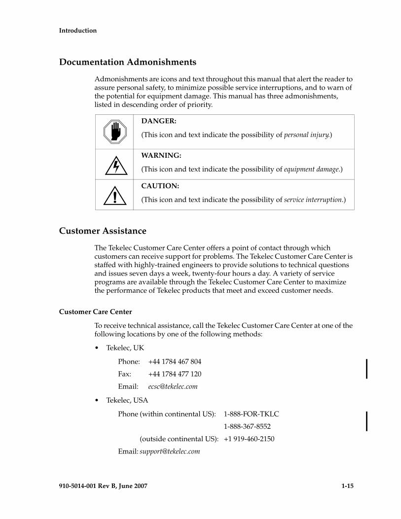
Admonishments are icons and text throughout this manual that alert the reader to assure personal safety, to minimize possible service interruptions, and to warn of the potential for equipment damage. This manual has three admonishments, listed in descending order of priority.
Customer Assistance
The Tekelec Customer Care Center offers a point of contact through which customers can receive support for problems. The Tekelec Customer Care Center is staffed with highly-trained engineers to provide solutions to technical questions and issues seven days a week, twenty-four hours a day. A variety of service programs are available through the Tekelec Customer Care Center to maximize the performance of Tekelec products that meet and exceed customer needs.
Customer Care Center
To receive technical assistance, call the Tekelec Customer Care Center at one of the following locations by one of the following methods:
• Tekelec, UK
Phone: +44 1784 467 804
Fax: +44 1784 477 120
Email: [email protected]
• Tekelec, USA
Phone (within continental US): 1-888-FOR-TKLC
1-888-367-8552
(outside continental US): +1 919-460-2150
Email: [email protected]
DANGER:
(This icon and text indicate the possibility of personal injury.)
WARNING:
(This icon and text indicate the possibility of equipment damage.)
CAUTION:
(This icon and text indicate the possibility of service interruption.)
1-16 910-5014-001 Rev B, June 2007
- Prel minary - Introduction
When the call is received, a Customer Service Report (CSR) is issued to record the request for service. Each CSR includes an individual tracking number.
Once a CSR is issued, Tekelec Customer Care Center determines the classification of the trouble. If a critical problem exists, emergency procedures are initiated. If the problem is not critical, information regarding the serial number of the system, COMMON Language Location Identifier (CLLI), initial problem symptoms (includes outputs and messages) is recorded. A primary Technical Services engineer is also assigned to work on the CSR and provide a solution to the problem. The CSR is closed when the problem is resolved.
Emergency Response
In the event of a critical service situation, emergency response is offered by Tekelec Customer Care Center twenty-four hours a day, seven days a week. The emergency response provides immediate coverage, automatic escalation, and other features to ensure that the critical situation is resolved as rapidly as possible.
A critical situation is defined as a problem with an EAGLE 5 ISS that severely affects service, traffic, or maintenance capabilities, and requires immediate corrective action. Critical problems affect service and/or system operation resulting in:
• A total system failure that results in loss of all transaction processing capability
• Significant reduction in system capacity or traffic handling capability
• Loss of the system’s ability to perform automatic system reconfiguration
• Inability to restart a processor or the system
• Corruption of system databases that requires service affecting corrective actions
• Loss of access for maintenance or recovery operations
• Loss of the system ability to provide any required critical or major trouble notification
Any other problem severely affecting service, capacity/traffic, billing, and maintenance capabilities may be defined as critical by prior discussion and agreement with the Tekelec Customer Care Center.
Acronyms
ACN....................................Application Context Name
ADL.....................................Application Data Loader
ARP .....................................Address Resolution Protocol
Introduction - Prel iminary -
910-5014-001 Rev B, June 2007 1-17
AuC.....................................Authentication Center
CC .......................................E.164 Country Code
CCRNDN...........................Country Code + Routing Number + National Directory Number
CdPA...................................Called Party Address
CgPA...................................Calling Party Address
CRP .....................................Circular Route Prevention
DCB.....................................Device Control Block
DCM ...................................Data Communications Module
DN.......................................Destinantion Number, called party telephone number
DRAM ................................Dynamic Random Access Memory
DSM ....................................Database Services Module
EPAP ...................................Eagle Provisioning Application Processor
ES.........................................Encoding Scheme
ETSI.....................................European Telecommunications Standards Institution
FAK .....................................Feature Access Key
FTR ......................................File Transfer Region
GDB ....................................G-Flex/G-Port/INP Database
GFDB ..................................G-Flex Database
G-Flex .................................GSM Flexible Numbering
GMSC .................................Gateway Mobile Switching Center
G-Port .................................GSM Mobile Number Portability
GPL .....................................Generic Program Load
GPSM-II..............................General Purpose Service Module II (Hardware)
GSM ....................................Global System for Mobile communications
GTA.....................................Global Title Address
GTAI ...................................Global Title Address Information
GTI ......................................Global Title Indicator
GTT .....................................Global Title Translation
HLR.....................................Home Location Register
1-18 910-5014-001 Rev B, June 2007
- Prel minary - Introduction
HOMERN...........................Home Network Routing Number Prefix
IAM .....................................Initial Address Message
IMSI.....................................International Mobile Station Identifier
IN.........................................Intelligent Network
INAP ...................................Intelligent Network Application Protocol
INP ......................................INAP-Based Number Portability
IP .........................................Internet Protocol
IS-41 ....................................International Standard 41, same as ANSI-41
ISDN ...................................Integrated Services Digital Network
ISUP ....................................ISDN User Part
ITU ......................................International Telecommunications Union
LIM......................................Link Interface Module
LNP .....................................Local Number Portability
LSS.......................................Local Subsystem
MAP....................................(1) Mobile Application Part (2) Mated APplication
MAS ....................................Maintenance and Administration Subsystem
MCAP .................................MAS Communication Application Processor Card
MEA....................................Mismatch of Equipment and Attributes
MDN ...................................Mobile Directory Number
MGT....................................Mobile Global Title
MIN.....................................Mobile Identification Number
MMI ....................................Man-Machine Interface
MNP....................................Mobile Number Portability
MPS.....................................Multi-Purpose Server (Multi-Platform Server)
MSRN .................................Mobile Station Roaming Number
MSC.....................................Mobile Switching Center
MSISDN..............................Mobile Station international ISDN number
MSU ....................................Message Signaling Unit
MT SMS ..............................Mobile Terminated Short Message Service
Introduction - Prel iminary -
910-5014-001 Rev B, June 2007 1-19
MTP ....................................Message Transfer Part
NAI .....................................Nature of Address Indicator
NC.......................................E.214 Network Code
NDC....................................E.164 National Destination Code
NP .......................................(1) Number Portability(2) Numbering Plan
NPA.....................................Numbering Plan Area
NPDB..................................Number Portability Database
NPV ....................................Numbering Plan Value
NSD.....................................Network Systems Division, Tekelec
OAI .....................................Object Access Interface
OAM ...................................Operation Administration & Maintenance
OAP ....................................Operations Support System/ Application Processor
OPS .....................................Operator Provisioning System
PDB .....................................Provisioning Database
PDBA ..................................Provisioning Database Application
PDBI....................................Provisioning Database Interface
PFS ......................................Product Functional Specification
PLMN .................................Public Land Mobile Network
PMTC..................................Peripheral Maintenance Control
RMTP..................................Reliable Multicast Transport Protocol
RN .......................................Routing Number
RNIDN ...............................Routing Number prefix + International dialed / Directory Number
RNNDN .............................Routing Number prefix + National dialed / Directory Number
RNSDN...............................Routing Number prefix + Subscriber dialed / Directory Number
RNxDN...............................Routing Number prefix + International dialed or National dialed or Subscriber dialed / Directory Number
RTDB...................................Real-Time Database
1-20 910-5014-001 Rev B, June 2007
- Prel minary - Introduction
SCCP ...................................Signaling Connection Control Part
SCP......................................Service Control Point
SDS......................................System Debug Services
SIM ......................................Subscriber Identity Module
SMS .....................................(1) Service Management System, or(2) Short Message Service
SN........................................Service Node
SNAI ...................................Service Nature of Address Indicator
SNP .....................................Service Numbering Plan
SOR .....................................Support for Optimal Routing
SP.........................................Signaling Point
SPC......................................Secondary Point Code
SRF ......................................Signaling Relay Function
SRI .......................................Send Routing Information
SS7 .......................................Signaling System 7
SSN......................................Subsystem Number
SSP.......................................Service Switching Point
STP ......................................Signal Transfer Point
TCAP ..................................Transaction Capabilities Application Part
TCP......................................Transmission Control Protocol
TFA......................................Transfer Allowed
TFC......................................Transfer Congested
TFP ......................................Transfer Prohibited
TLNP...................................Tiggerless Local Number Portability
TSM.....................................Translation Service Module
TT ........................................Translation Type
UAM ...................................Unsolicited Alarm Message
UDP.....................................User Datagram Protocol
UDTS...................................Unit Data Transfer Service
UIM .....................................Unsolicited Information Message

Introduction - Prel iminary -
910-5014-001 Rev B, June 2007 1-21
VLR .....................................Visitor Location Register
VMSC .................................Voice Mail Service Center
VSCCP................................VxWorks Signaling Connection Control Part

1-22 910-5014-001 Rev B, June 2007
- Prel minary - Introduction
910-5014-001 Rev B, June 2007 2-1
- Draft -
2
Feature Description
G-Port MNP Overview ................................................................................... 2–2
Feature Description .................................................................................. 2–2
G-Port Call Flows...................................................................................... 2–5
PPSMS Call Flows................................................................................... 2–12
ISUP NP with EPAP Call Flows............................................................ 2–19
Subscriber Data Provisioning................................................................ 2–22
Database Overview................................................................................. 2–24
EPAP (EAGLE Provisioning Application Processor)......................... 2–26
DSM (Database Service Module) Cards .............................................. 2–27
DSM Provisioning and Reload.............................................................. 2–29
Network Connections ............................................................................ 2–31
Network Perspectives ............................................................................ 2–35
Serviceability Hints................................................................................. 2–37
G-Port Considerations............................................................................ 2–38
General Requirements............................................................................ 2–40
G-Port Protocol .............................................................................................. 2–43
Main Functions........................................................................................ 2–43
G-Port Message Handling ..................................................................... 2–49
G-Port SCCP Service Re-Route Capability.......................................... 2–51
Prepaid SMS Intercept Protocol................................................................... 2–55
Main Functions........................................................................................ 2–55
2-2 910-5014-001 Rev B, June 2007
- Prel- Draft -minary - Feature Description
SMS Prepaid Intercept Message Handling..........................................2–57
PPSMS Without G-Port MNP................................................................2–58
G-Port MNP Overview
Throughout the world, an increasing number of governments are mandating that telecommunications network operators support service provider number portability. It is primarily intended to promote competition among service providers. It applies to both wireline and mobile phone networks. In particular, the G-Port MNP (Mobile Number Portability) feature is focused on service provider portability in GSM (Global System for Mobile communications) networks.
Service provider portability allows a consumer to change service providers while retaining his phone number. While the advent of number portability is good news for consumers, its implementation can present many challenges for network operators. G-Port MNP minimizes those challenges for GSM network operators, while enabling them to efficiently meet their regulatory obligations.
Feature Description
G-Port MNP implements Mobile Number Portability for GSM networks according to the ETSI GSM 03.66 standard. The focus is on service provider portability among GSM networks in a defined portability cluster, usually a country. With service provider portability, subscribers can change operators while retaining their MSISDN (Mobile Station international ISDN number) number. The MSISDN is the number dialed by someone trying to reach the subscriber. Their IMSI (International Mobile Station Identifier) number is not portable. The IMSI identifies the SIM (Subscriber Identity Module) card, which modularly plugs into the GSM handset.
The MNP Circular Route Prevention (MNPCRP) feature is an extension of the G-Port MNP feature which helps in cases of circular routing caused by incorrect information in one or more of the network number portability databases. For example, a subscriber may have ported from network A to network B. Network A has the correct routing information, indicating the subscriber now belongs to network B. However, network B may have incorrect routing information, indicating that the subscriber still belongs to network A. In this case, network A routes the call to network B, based on its portability data, but network B routes the call back to network A, based on its incorrect data. This results in a circular route. The MNPCRP feature provides logic to prevent this scenario.
The Prepaid Short Message Service (PPSMS) Intercept feature is based on the G-Port MNP feature and applies only to mobile originated SMS, those messages sent from a mobile handset through an Mobile Switching Center (MSC) to the Short Message Service Center (SMSC). PPSMS Intercept screens incoming messages from MSC based on the MAP operation code. Message Discrimination determines whether the sender's MSISDN is retrieved and a database lookup
Feature Description - Prel- Draft -iminary -
910-5014-001 Rev B, June 2007 2-3
performed. Database lookup determines if the MSISDN belongs to a contract subscriber, and the message routed to the SMSC, or if the MSISDN belongs to a prepaid subscriber, and the message diverted to a third-party IN platform for a credit check before allowing the message to be delivered to the SMSC.
The MNP Check for Mobile Originated (MO) SMS feature is a fraud prevention enhancement to the PPSMS feature. With this feature enabled, the EAGLE 5 ISS filters incoming messages based on the MAP Operation Code. If the message is a MO Forward Short Message (MO FSM), the originating subscriber's MSISDN number is used to search the G-Port Mobile Number Portability database. If a match is found indicating the subscriber has been ported-out, the EAGLE 5 ISS then uses the destination SMSC address obtained from the SCCP CdPA to search a list of "home network" SMSC addresses. If a match is found, indicating the ported-out subscriber is fraudulently attempting to send SMS using the old network's SMSC, the message is discarded and an error message is generated and returned to the originating MSC.
The Multiple Country Code (MULTCC) feature supports up to 10 MULTCCs for customers having one MNP node servicing several countries, or areas with differing country codes. The MULTCCs are not used for conditioning of non-International numbers to International format for database lookup. The MULTCCs are used for the construction of the Mobile Station Roaming Number (MSRN) parameter in the case of a Send Routing Information acknowledgement (SRI-ack) response from G-Port, and in certain cases for the formulation of the SCCP CdPA. The DEFCC parameter in STPOPTS is used for conditioning of numbers to International format when necessary, and also for constructing the MSRN and SCCP CdPA parameters in addition to a MULTCC list. The MULTCC list is optional. If no values are provisioned, G-Port uses the DEFCC to process messages. If values are provisioned, G-Port automatically utilizes both the DEFCC and the MULTCC to process messages. The chg-gsmopts command along with the MULTCC and NMULTCC parameters are used to provision Multiple Country Code list entries.
The MSISDN Truncation Support for G-Port MNP feature, is an optional feature that allows an operator to specify a certain number of digits to be deleted from the beginning of the National MSISDN (MSISDN without Country Code prior to formulating the MSRN parameter of the SRI-ack response. This feature only changes the behavior of the encoding of the MAP MSRN parameter in a SRI-ack formulated by the EAGLE 5 ISS. It does not affect the encoding of any other parameters or any other messages processed by G-Port. The International MSISDN is 12 digits long, and the RN is 5 digits long. So when the RN is added to form the MSRN parameter, it will exceed 15 digits in length. Some carriers require MSISDN digits to be truncated when formulating MSRN parameter of SRI-ack response in G-Port in order to maintain max 15 digits length. This feature works in conjunction with the MULTCC Support feature. The MULTCC table is used to determine which digits are the CC and which digits are the National MSISDN. If a match is not found on the leading digits of the International MSISDN when searched against the MULTCC list, then the truncation is not performed, and
2-4 910-5014-001 Rev B, June 2007
- Prel- Draft -minary - Feature Description
standard G-Port processing is followed. The chg-gsmopts command along with the MISDNTRUNC parameter is used to set-up the MSISDN Truncation Support feature.
The ISUP NP with EPAP feature enables the EAGLE 5 ISS to intercept ISUP Initial Address Message (IAM) and to perform the NP Database (NPDB) lookup based on the Called Party Number (CdPN) of the IAM. The EAGLE 5 ISS prepends a Routing Number (RN) to the CdPN if the CdPN is a ported out number or prepends a SubNet prefix if the CdPN is ported-in or never been ported number before relaying the IAM message to its destination.
The purpose of the ISUP NP with EPAP feature is to prepend a prefix (a SubNet prefix or RN) to the CdPN of an IAM message if the CdPN is a ported in (including never been ported) or a ported out DN before relaying the message to its destination. The prefix provides the recipient switch a means to differentiate a call so that different billing rates or routing can be applied to the call.
The ISUP NP with EPAP feature is enabled and turned-on with a Feature Activation Key.
The DigitAction Expansion feature provides more flexibility to formulate the SCCP Called Party Address (SCCP) Global Title Address (GTA) field of the MAP messages relayed by G-Port.
Without DigitAction Expansion, G-Port supports four options (none, insert, prefix, and replace) to overwrite the SCCP CdPA GTA field. With DigitAction Expansion, four additional options (delcc, delccprefix, spare1, and spare2) are included to overwrite the SCCP CdPA GTA field.
DigitAction Expansion is provisioned via the PDBI Enter Network Entity or Update Network Entity commands. DigitAction Expansion can also be modified via the Add an NE and Update an NE GUI screens.
The G-Port SCCP Service Re-Route feature is used when the G-Port subscriber database is incoherent with MPS data and the GTT data is valid. The G-Port SCCP Service Re-Route feature provides the capability to re-route the traffic from the EAGLE 5 ISS to other G-Port subscriber database nodes and inform the originating nodes to re-route the G-Port service related traffic to other G-Port service nodes.
The G-Port SCCP Service Re-Route feature is designed to handle and control re-routing of G-Port traffic from an affected node to alternate nodes within an operators network. This feature is an optional feature and doesn't affect the normal G-Port functionality. This feature also provides the option to mark G-Port OFFLINE to perform a controlled re-routing during this state.
The ETSI standards are defined so that GSM carriers can choose to implement either Signaling Relay Function (SRF)-based (using MAP protocol) MNP or IN-based (using INAP protocol) MNP. G-Port supports only the SRF-based solution for MNP. (INAP-based MNP processing is similar to wireline networks; this function is supported by the INP feature.)
Feature Description - Prel- Draft -iminary -
910-5014-001 Rev B, June 2007 2-5
SRF-based MNP processing involves the “intercepting” of existing MAP messages to check for ported numbers. For call-related messages, G-Port acts as a “NP HLR,” in the case where the number has been exported, by responding to the switch with a MAP SRI ack message. For calls to imported numbers and non-call related messages, G-Port performs message relay.
The ETSI standards for SRF-based MNP define two routing options, direct routing and indirect routing. G-Port supports both options:
• With direct routing, the network where the call is originated is responsible for determining whether the called party has ported and routing the call to the new subscription network.
• With indirect routing, this is the responsibility of the network that originally owned the number.
G-Port MNP is based on the EAGLE 5 ISS platform. It is deployed in a node that is also performing the STP function.
Number lengths vary between countries and may even vary within a country. As a result, the G-Port MNP subscriber database structure supports numbers of varying length in a flexible way without necessitating software modifications. A maximum number length of 15 digits for ported numbers is supported. This length is based on the maximum length for MSISDN numbers as defined in the ETSI GSM 03.03 standard.
NOTES:
• G-Port is turned on, but not off, via a Feature Access Key (FAK).
• The G-Port MNP, A-Port, IGM, G-Flex C7 Relay, and INP features can run concurrently on an EAGLE 5 ISS node.
• When G-Port and G-Flex are run on the same node, interactions between the two features must be addressed.
• G-Port MNP and North American LNP are mutually exclusive on an EAGLE 5 ISS node.
• G-Port SCCP Service Re-Route Capability is not supported for the Prepaid SMS Intercept feature.
• When G-Port MNP and A-Port or IGM features run concurrently on the same EAGLE 5 ISS node, the service name is changed to MNP.
G-Port Call Flows
This section contains several illustrative sample call flows: G-Port supports all call flows identified in GSM 03.66 other than noted exceptions. This section contains a mix of call flows using both indirect and direct routing.
2-6 910-5014-001 Rev B, June 2007
- Prel- Draft -minary - Feature Description
These call flows, including calls to imported or non-ported numbers, show only one possible scenario regarding how messages are routed in the network and where various stages of GTT are performed. G-Port may perform intermediate or final GTT depending on the message received and provisioned data.
Several call flows refer to non-call related messages. Examples of non-call related messages are SRI for Short Message Service and SRI for Optimal Routing.
In all G-Port call flows, the MSISDN used for the database search is converted to an international number, if necessary, prior to the database search.
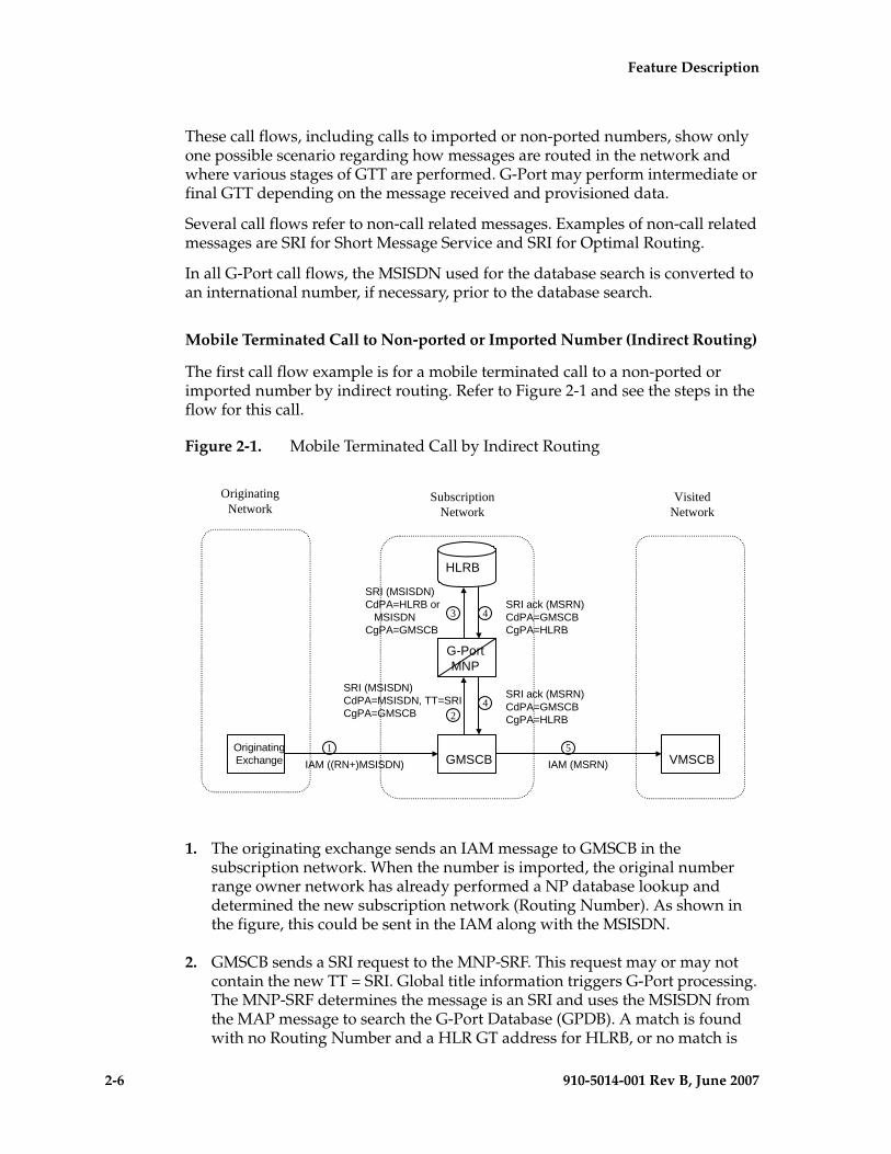
Mobile Terminated Call to Non-ported or Imported Number (Indirect Routing)
The first call flow example is for a mobile terminated call to a non-ported or imported number by indirect routing. Refer to Figure 2-1 and see the steps in the flow for this call.
Figure 2-1. Mobile Terminated Call by Indirect Routing
1. The originating exchange sends an IAM message to GMSCB in the subscription network. When the number is imported, the original number range owner network has already performed a NP database lookup and determined the new subscription network (Routing Number). As shown in the figure, this could be sent in the IAM along with the MSISDN.
2. GMSCB sends a SRI request to the MNP-SRF. This request may or may not contain the new TT = SRI. Global title information triggers G-Port processing. The MNP-SRF determines the message is an SRI and uses the MSISDN from the MAP message to search the G-Port Database (GPDB). A match is found with no Routing Number and a HLR GT address for HLRB, or no match is
1
43
24
OriginatingNetwork
VisitedNetwork
SubscriptionNetwork
IAM ((RN+)MSISDN)
SRI (MSISDN)CdPA=MSISDN, TT=SRICgPA=GMSCB
SRI (MSISDN)CdPA=HLRB or MSISDNCgPA=GMSCB
SRI ack (MSRN)CdPA=GMSCBCgPA=HLRB
IAM (MSRN)OriginatingExchange VMSCB
HLRB
G-PortMNP
GMSCB5
SRI ack (MSRN)CdPA=GMSCBCgPA=HLRB
Feature Description - Prel- Draft -iminary -
910-5014-001 Rev B, June 2007 2-7
found and falls through to GTT, producing a routing to HLRB. Alternatively, GTT could route to another node, possibly in a different network, but that is not illustrated here.
3. The message is routed to HLRB.
4. HLRB responds to GMSCB with a SRI ack. This message can be GT routed through the STP or MTP routed.
5. GMSCB sends an IAM with the roaming number to the visited network.
Mobile Originated/Terminated Call to an Exported Number (Direct Routing)
This call flow example is for a call that is mobile originated or terminated to an exported number by direct routing. Refer to Figure 2-2 and see the steps in the flow for this call.
Figure 2-2. Call to an Exported Number by Direct Routing
This call flow assumes the originating network is not the subscription network. If indirect routing were used in this example, the originating network would first route the call to the number range owner network, according to pre-portability rules, where the MNP-SRF and NPDB are accessed to locate the Routing Number.
1. When the call is originated, VMSCA sends an IAM message to GMSCA.
2. GMSCA sends a SRI request to the MNP-SRF. This may or may not contain the new TT = SRI. Global title information triggers G-Port processing. The MNP-SRF determines the message is an SRI and uses the MSISDN from the
1
32
4
OriginatingNetwork
IAM (MSISDN)
SRI (MSISDN)CdPA=MSISDN, TT=SRICgPA=GMSCA
SRI ack (RN + MSISDN)CdPA=GMSCACgPA=G-Port_MNP
IAM ((RN+)MSISDN)VMSCA
G-PortMNP
GMSCA
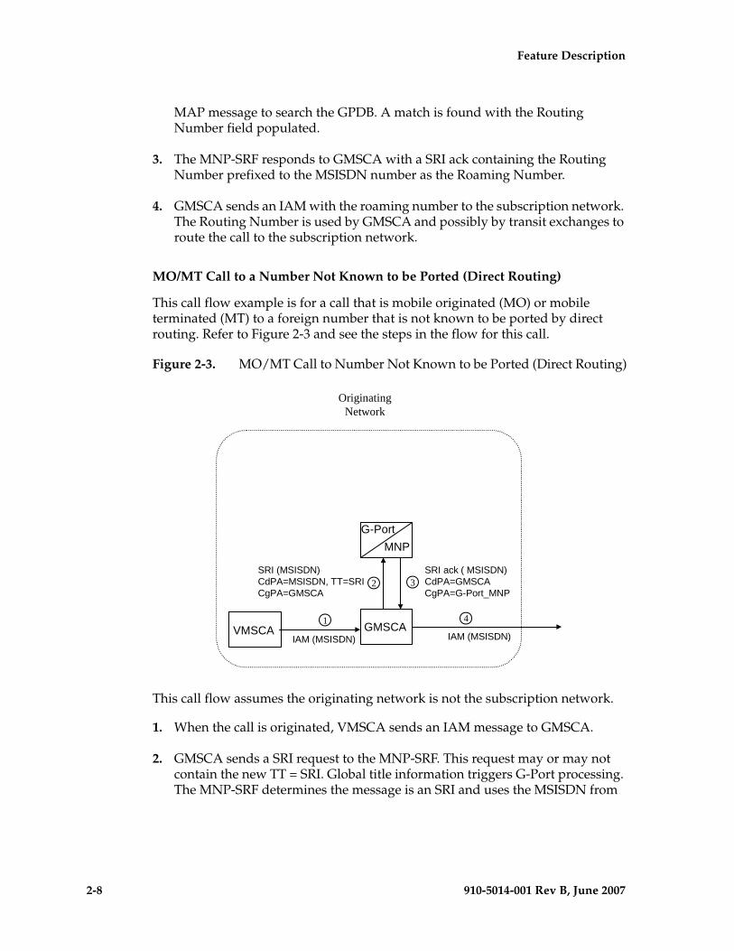
2-8 910-5014-001 Rev B, June 2007
- Prel- Draft -minary - Feature Description
MAP message to search the GPDB. A match is found with the Routing Number field populated.
3. The MNP-SRF responds to GMSCA with a SRI ack containing the Routing Number prefixed to the MSISDN number as the Roaming Number.
4. GMSCA sends an IAM with the roaming number to the subscription network. The Routing Number is used by GMSCA and possibly by transit exchanges to route the call to the subscription network.
MO/MT Call to a Number Not Known to be Ported (Direct Routing)
This call flow example is for a call that is mobile originated (MO) or mobile terminated (MT) to a foreign number that is not known to be ported by direct routing. Refer to Figure 2-3 and see the steps in the flow for this call.
Figure 2-3. MO/MT Call to Number Not Known to be Ported (Direct Routing)
This call flow assumes the originating network is not the subscription network.
1. When the call is originated, VMSCA sends an IAM message to GMSCA.
2. GMSCA sends a SRI request to the MNP-SRF. This request may or may not contain the new TT = SRI. Global title information triggers G-Port processing. The MNP-SRF determines the message is an SRI and uses the MSISDN from
OriginatingNetwork
IAM (MSISDN)
SRI (MSISDN)CdPA=MSISDN, TT=SRICgPA=GMSCA
SRI ack ( MSISDN)CdPA=GMSCACgPA=G-Port_MNP
IAM (MSISDN)VMSCA
G-PortMNP
GMSCA
32
1 4
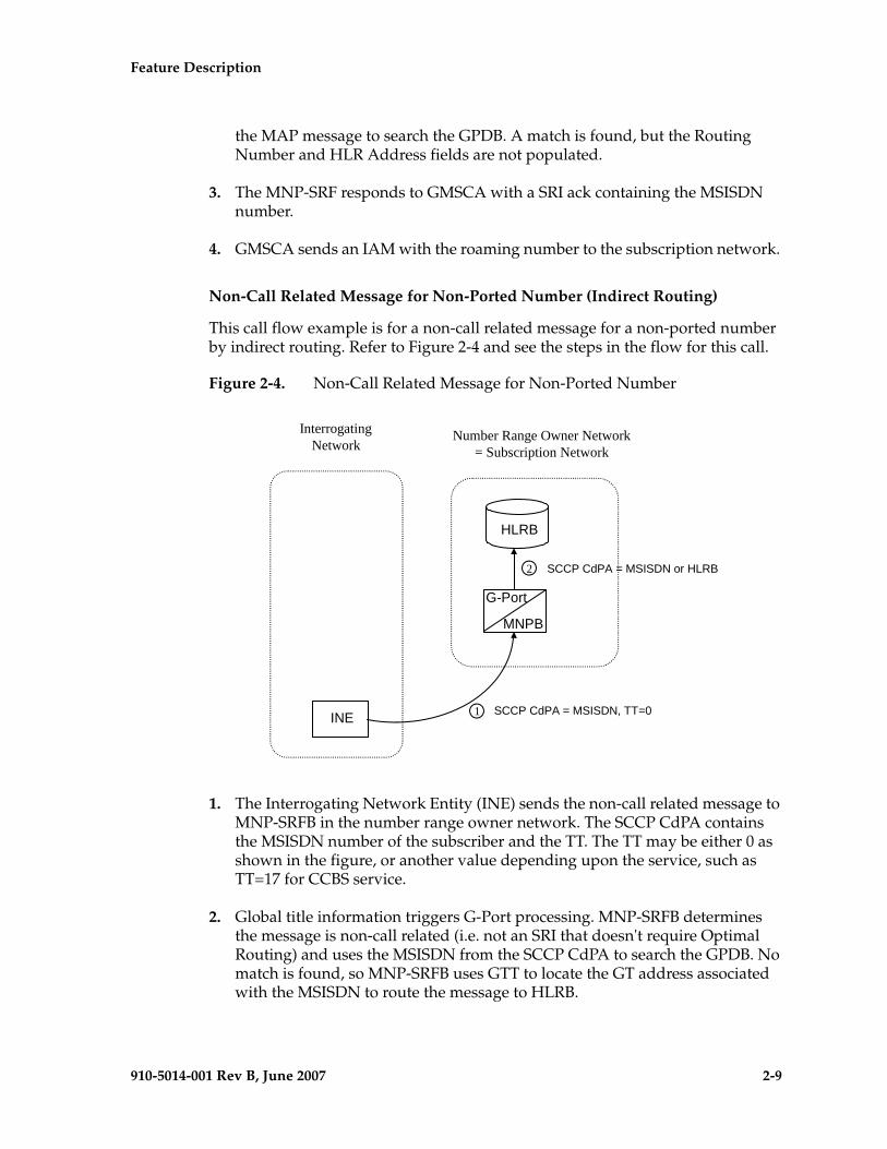
Feature Description - Prel- Draft -iminary -
910-5014-001 Rev B, June 2007 2-9
the MAP message to search the GPDB. A match is found, but the Routing Number and HLR Address fields are not populated.
3. The MNP-SRF responds to GMSCA with a SRI ack containing the MSISDN number.
4. GMSCA sends an IAM with the roaming number to the subscription network.
Non-Call Related Message for Non-Ported Number (Indirect Routing)
This call flow example is for a non-call related message for a non-ported number by indirect routing. Refer to Figure 2-4 and see the steps in the flow for this call.
Figure 2-4. Non-Call Related Message for Non-Ported Number
1. The Interrogating Network Entity (INE) sends the non-call related message to MNP-SRFB in the number range owner network. The SCCP CdPA contains the MSISDN number of the subscriber and the TT. The TT may be either 0 as shown in the figure, or another value depending upon the service, such as TT=17 for CCBS service.
2. Global title information triggers G-Port processing. MNP-SRFB determines the message is non-call related (i.e. not an SRI that doesn't require Optimal Routing) and uses the MSISDN from the SCCP CdPA to search the GPDB. No match is found, so MNP-SRFB uses GTT to locate the GT address associated with the MSISDN to route the message to HLRB.
InterrogatingNetwork
Number Range Owner Network= Subscription Network
G-Port
MNPB
HLRB
INE 1 SCCP CdPA = MSISDN, TT=0
2 SCCP CdPA = MSISDN or HLRB
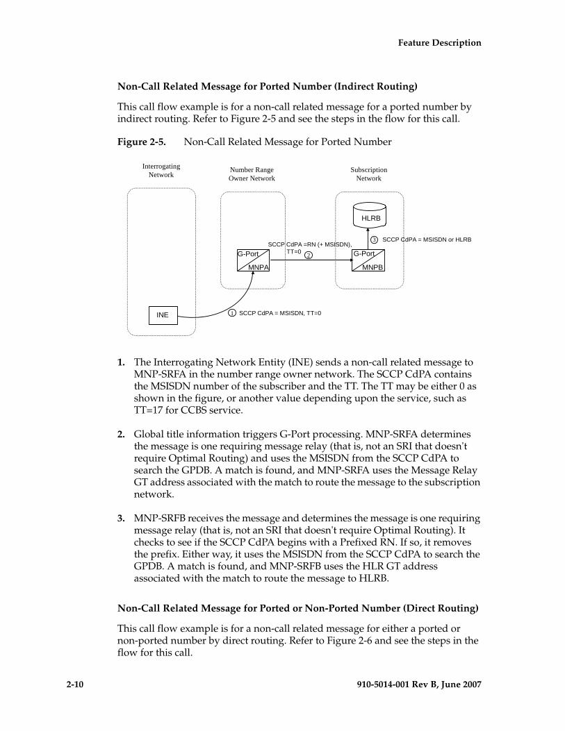
2-10 910-5014-001 Rev B, June 2007
- Prel- Draft -minary - Feature Description
Non-Call Related Message for Ported Number (Indirect Routing)
This call flow example is for a non-call related message for a ported number by indirect routing. Refer to Figure 2-5 and see the steps in the flow for this call.
Figure 2-5. Non-Call Related Message for Ported Number
1. The Interrogating Network Entity (INE) sends a non-call related message to MNP-SRFA in the number range owner network. The SCCP CdPA contains the MSISDN number of the subscriber and the TT. The TT may be either 0 as shown in the figure, or another value depending upon the service, such as TT=17 for CCBS service.
2. Global title information triggers G-Port processing. MNP-SRFA determines the message is one requiring message relay (that is, not an SRI that doesn't require Optimal Routing) and uses the MSISDN from the SCCP CdPA to search the GPDB. A match is found, and MNP-SRFA uses the Message Relay GT address associated with the match to route the message to the subscription network.
3. MNP-SRFB receives the message and determines the message is one requiring message relay (that is, not an SRI that doesn't require Optimal Routing). It checks to see if the SCCP CdPA begins with a Prefixed RN. If so, it removes the prefix. Either way, it uses the MSISDN from the SCCP CdPA to search the GPDB. A match is found, and MNP-SRFB uses the HLR GT address associated with the match to route the message to HLRB.
Non-Call Related Message for Ported or Non-Ported Number (Direct Routing)
This call flow example is for a non-call related message for either a ported or non-ported number by direct routing. Refer to Figure 2-6 and see the steps in the flow for this call.
InterrogatingNetwork
Number RangeOwner Network
G-Port
MNPA
G-Port
MNPB
SubscriptionNetwork
HLRB
INE
SCCP CdPA =RN (+ MSISDN), TT=0
SCCP CdPA = MSISDN, TT=01
2
3 SCCP CdPA = MSISDN or HLRB
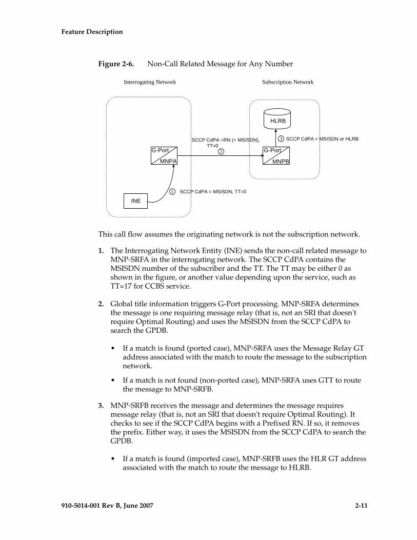
Feature Description - Prel- Draft -iminary -
910-5014-001 Rev B, June 2007 2-11
Figure 2-6. Non-Call Related Message for Any Number
This call flow assumes the originating network is not the subscription network.
1. The Interrogating Network Entity (INE) sends the non-call related message to MNP-SRFA in the interrogating network. The SCCP CdPA contains the MSISDN number of the subscriber and the TT. The TT may be either 0 as shown in the figure, or another value depending upon the service, such as TT=17 for CCBS service.
2. Global title information triggers G-Port processing. MNP-SRFA determines the message is one requiring message relay (that is, not an SRI that doesn't require Optimal Routing) and uses the MSISDN from the SCCP CdPA to search the GPDB.
• If a match is found (ported case), MNP-SRFA uses the Message Relay GT address associated with the match to route the message to the subscription network.
• If a match is not found (non-ported case), MNP-SRFA uses GTT to route the message to MNP-SRFB.
3. MNP-SRFB receives the message and determines the message requires message relay (that is, not an SRI that doesn't require Optimal Routing). It checks to see if the SCCP CdPA begins with a Prefixed RN. If so, it removes the prefix. Either way, it uses the MSISDN from the SCCP CdPA to search the GPDB.
• If a match is found (imported case), MNP-SRFB uses the HLR GT address associated with the match to route the message to HLRB.
Interrogating Network Subscription Network
G-Port
MNPB
HLRB
INE
G-Port
MNPA
SCCP CdPA =RN (+ MSISDN), TT=0
SCCP CdPA = MSISDN, TT=01
2
SCCP CdPA = MSISDN or HLRB3
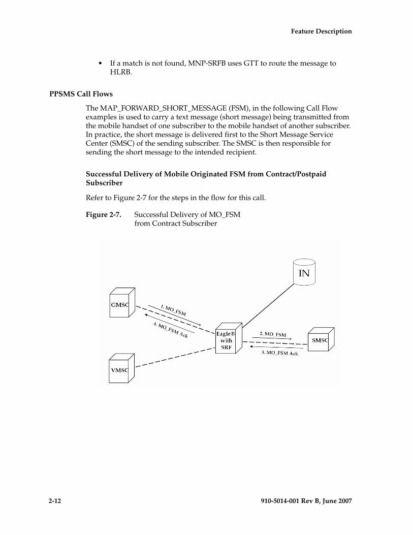
2-12 910-5014-001 Rev B, June 2007
- Prel- Draft -minary - Feature Description
• If a match is not found, MNP-SRFB uses GTT to route the message to HLRB.
PPSMS Call Flows
The MAP_FORWARD_SHORT_MESSAGE (FSM), in the following Call Flow examples is used to carry a text message (short message) being transmitted from the mobile handset of one subscriber to the mobile handset of another subscriber. In practice, the short message is delivered first to the Short Message Service Center (SMSC) of the sending subscriber. The SMSC is then responsible for sending the short message to the intended recipient.
Successful Delivery of Mobile Originated FSM from Contract/Postpaid Subscriber
Refer to Figure 2-7 for the steps in the flow for this call.
Figure 2-7. Successful Delivery of MO_FSM from Contract Subscriber
Feature Description - Prel- Draft -iminary -
910-5014-001 Rev B, June 2007 2-13
1. The Gateway Mobile Switching Center (GMSC) sends the Mobile Originated Forward Short Message (MO_FSM) to the EAGLE 5 ISS with PPSMS (TC BEGIN).
Based on MTP DPC = EAGLE 5 ISS's point code and SCCP CdPA TT, NP, NAI, SSN, and GTI, the message is pre-selected for PPSMS service. If service is not PPSMS, the message falls through to GTT.)
Next, the MAP OpCode and SCCP CgPA GTA are examined. The OpCode is MO_FSM and the CgPA GTA is not from one of the IN platforms, therefore, PPSMS processing continues. (If the OpCode is not MO_FSM, or if CgPA GTA is for one of the IN platforms, the message falls through to GTT.)
The EAGLE 5 ISS queries the DB using the sender's MSISDN from the OA field in the MAP portion of message.
MSISDN is present in the database, but "Portability Type" is neither prepaid1 nor prepaid2, meaning the sender is not a prepaid subscriber.
2. The EAGLE 5 ISS therefore GTT-routes the MO_FSM to the SMSC (TC BEGIN).
3. The SMSC returns the MO_FSM_ack (TC END).
4. One of two possibilities:
a. The SMSC sends the MO_FSM_ack route-on-SSN to the GMSC, then the SRF will simply MTP route the MO_FSM_ack to the GMSC. G-Port is not involved.
b. The SMSC sends the MO_FSM_ack route-on-GT, and the service selectors indicate G-Port/PPSMS. CdPA SSN = GMSC, which is same as SMSC, so PPSMS is selected. As PPSMS decodes message, it discovers it is a TC END. Therefore, the message falls through to normal GTT and is routed to the GMSC.
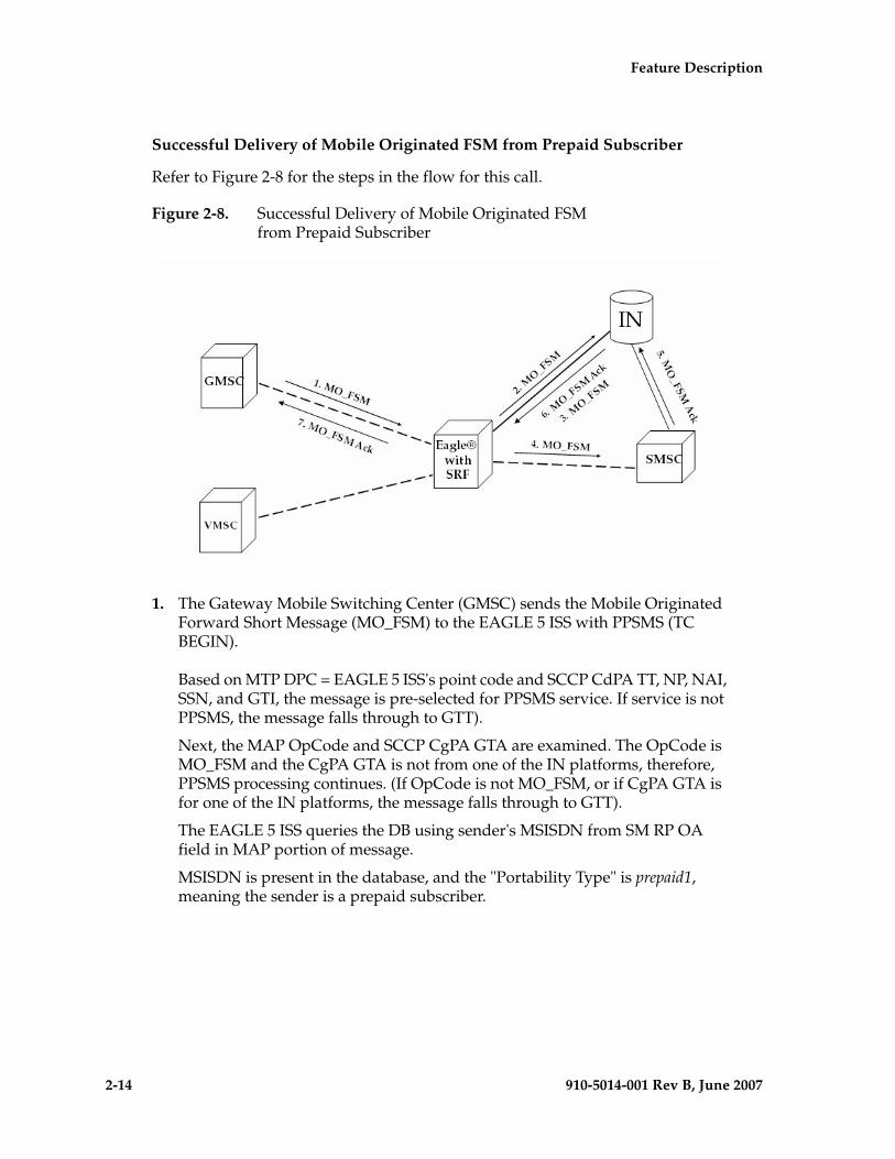
2-14 910-5014-001 Rev B, June 2007
- Prel- Draft -minary - Feature Description
Successful Delivery of Mobile Originated FSM from Prepaid Subscriber
Refer to Figure 2-8 for the steps in the flow for this call.
Figure 2-8. Successful Delivery of Mobile Originated FSMfrom Prepaid Subscriber
1. The Gateway Mobile Switching Center (GMSC) sends the Mobile Originated Forward Short Message (MO_FSM) to the EAGLE 5 ISS with PPSMS (TC BEGIN).
Based on MTP DPC = EAGLE 5 ISS's point code and SCCP CdPA TT, NP, NAI, SSN, and GTI, the message is pre-selected for PPSMS service. If service is not PPSMS, the message falls through to GTT).
Next, the MAP OpCode and SCCP CgPA GTA are examined. The OpCode is MO_FSM and the CgPA GTA is not from one of the IN platforms, therefore, PPSMS processing continues. (If OpCode is not MO_FSM, or if CgPA GTA is for one of the IN platforms, the message falls through to GTT).
The EAGLE 5 ISS queries the DB using sender's MSISDN from SM RP OA field in MAP portion of message.
MSISDN is present in the database, and the "Portability Type" is prepaid1, meaning the sender is a prepaid subscriber.
Feature Description - Prel- Draft -iminary -
910-5014-001 Rev B, June 2007 2-15
2. The EAGLE 5 ISS forwards the MO_FSM to the IN Platform (TC BEGIN) associated with "prepaid1", after checking mated application or mated relay node table.
NOTE: The Portability Types prepaid1 and prepaid2 are used to select which of the two IN platforms the message should be sent. prepaid1 indicates one and prepaid2 the other.
3. The IN Platform checks the account, finds there is enough credit to send the message, opens a new TCAP dialogue, and returns the MO_FSM to the SRF (TC BEGIN-2).
4. The message arrives at EAGLE 5 ISS and is again selected for PPSMS service based on CdPA TT, NP, NAI, GTI, and CdPA SSN = SMSC. The OpCode is MO_FSM but the SCCP CgPA GTA is IN platform, therefore, PPSMS service is not indicated and the message falls through to GTT and is routed to the SMSC.
5. The SMSC returns the MO_FSM_ack to the IN platform (TC END-2). There are two possibilities:
a. The SMSC sends the MO_FSM_ack route-on-SSN to the IN platform, then the SRF will simply MTP route the MO_FSM_ack to the IN platform. G-Port is not involved.
b. The SMSC sends the MO_FSM_ack route-on-GT, and the service selectors indicate G-Port/PPSMS. CdPA SSN = GMSC, which is same as SMSC, so PPSMS is selected. As PPSMS decodes the message, it discovers it is a TC END. Therefore, the message falls through to normal GTT and is routed to the GMSC.
6. The IN Platform transfers the MO_FSM_ack to the first transaction and returns the MO_FSM_ack to the SRF (TC END).
7. One of two possibilities:
a. The IN platform sends the MO_FSM_ack route-on-SSN to the GMSC, then the SRF will simply MTP route the MO_FSM_ack to the GMSC. G-Port is not involved.
b. The IN platform sends the MO_FSM_ack route-on-GT, and the service selectors indicate G-Port/PPSMS. CdPA SSN = GMSC, which is same as SMSC, so PPSMS is selected. PPSMS decodes message, discovers it is a TC END, and the message falls through to normal GTT and is routed to the GMSC.
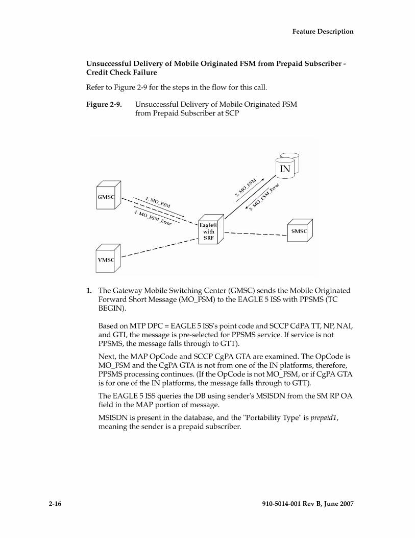
2-16 910-5014-001 Rev B, June 2007
- Prel- Draft -minary - Feature Description
Unsuccessful Delivery of Mobile Originated FSM from Prepaid Subscriber - Credit Check Failure
Refer to Figure 2-9 for the steps in the flow for this call.
Figure 2-9. Unsuccessful Delivery of Mobile Originated FSM from Prepaid Subscriber at SCP
1. The Gateway Mobile Switching Center (GMSC) sends the Mobile Originated Forward Short Message (MO_FSM) to the EAGLE 5 ISS with PPSMS (TC BEGIN).
Based on MTP DPC = EAGLE 5 ISS's point code and SCCP CdPA TT, NP, NAI, and GTI, the message is pre-selected for PPSMS service. If service is not PPSMS, the message falls through to GTT).
Next, the MAP OpCode and SCCP CgPA GTA are examined. The OpCode is MO_FSM and the CgPA GTA is not from one of the IN platforms, therefore, PPSMS processing continues. (If the OpCode is not MO_FSM, or if CgPA GTA is for one of the IN platforms, the message falls through to GTT).
The EAGLE 5 ISS queries the DB using sender's MSISDN from the SM RP OA field in the MAP portion of message.
MSISDN is present in the database, and the "Portability Type" is prepaid1, meaning the sender is a prepaid subscriber.

Feature Description - Prel- Draft -iminary -
910-5014-001 Rev B, June 2007 2-17
2. The EAGLE 5 ISS forwards the MO_FSM to the IN Platform (TC BEGIN) associated with prepaid1.
NOTE: The Portability Types prepaid1 and prepaid2 are used to select which of the two IN platforms the message should be sent to. prepaid1 indicates one and prepaid2 the other.
3. The IN Platform checks the account, finds there is not enough credit to send the message, and rejects the message by returning a MO_FSM_Neg_Response to the SRF (TC END).
4. One of two possibilities:
a. The IN platform sends the MO_FSM_Neg_Response route-on-SSN, then the SRF will simply MTP route the MO_FSM_Neg_Response to the GMSC. G-Port is not involved.
b. The IN platform sends the MO_FSM_Neg_Response route-on-GT, and the service selectors indicate G-Port/PPSMS. CdPA SSN = GMSC, which is same as SMSC, so PPSMS service is selected. PPSMS decodes message, discovers it is a TC END, and the message falls through to normal GTT and is routed to the GMSC.
Portability Check for Mobile Originated SMS
Refer to the following steps in the flow for this call.
The EAGLE 5 ISS will perform following with respect to MNP SMS Feature functionality.
1. The EAGLE 5 ISS receives an UDT message and checks if the service selector matches G-Port, if so continue on to Step 2, If the service selector is not G-Port, the message falls through to GTT.
2. The EAGLE 5 ISS performs CdPA SSN discrimination. CdPA SSN = SMSC, PPSMS service is selected. (If CdPA SSN is HLR, G-Port MNP service is selected. If SSN is neither SMSC nor HLR, the message falls through to GTT.)
3. Next the MAP OpCode is examined. If the OpCode is MO_FSM, PPSMS processing continues. (If the OpCode is not MO_FSM, the message falls through to GTT.)
2-18 910-5014-001 Rev B, June 2007
- Prel- Draft -minary - Feature Description
4. If The PPSMS feature is ON and the message is from one of the IN Platforms (PPSMS Servers), the message exists from MNP SMS feature functionality and falls through to PPSMS processing. If not, MNP SMS processing continues with Step 5.
5. If the MNP SMS feature is ON, the MSISDN number is used to search the G-Port Mobile Number Portability subscriber database. If the MNP SMS feature is not ON, the message falls through to GTT.
6. If the MSISDN Number is found in the PDB/DN table, then the portability type of the subscriber is checked for Ported-out/ Not Known/ FNPTFN and processing continues. If the MSISDN Number is not found in the PDB/DN table, the message falls through to GTT. If the portability type is Prepaid-1/Prepaid-2 the message falls through to GTT.
7. The SCCP CdPA Addressis used to search the list of "home network" SMSC addresses. If a match is found, the ported-out subscriber is fraudulently attempting to send SMS using the old network's SMSC. The message is discarded, UIM #1129 is issued, and an error message is generated and returned to the originating MSC. If the message is not on the list, the message falls through to GTT.
8. The message will be discarded, Print an UIM #1129 and an error message is generated and returned to the originating MSC. The message exists from MNP SMS feature functionality.
9. It's a fall through case. Exit from MNP SMS feature functionality and continue with Normal GTT processing.
10. If the message is from one of the IN Platforms (PPSMS Servers), The message exists from MNP SMS feature functionality and falls through to PPSMS processing. If the message is not from one of the PPSMS Servers processing continues with step 13
11. The originating subscriber's Mobile Subscriber Integrated Services Digital Network (MSISDN) number (i.e. phone number) will be used to search the G-Port Mobile Number Portability subscriber database. If the MSISDN Number is found in the PDB / DN table, then continue on to Step 12. Otherwise, exit from MNP SMS feature functionality and continue with Normal GTT processing.
12. Check the portability type of the subscriber, If it matches "Prepaid1/Prepaid2" go on to Step 16 else continue with Step 13.
13. If the subscriber portability type is "Ported out / FNPTFN/ Not Known" and MNP SMS feature is also ON, then go to Step 7. Otherwise, exit from MNP SMS feature functionality and continue with Normal GTT processing.
Feature Description - Prel- Draft -iminary -
910-5014-001 Rev B, June 2007 2-19
14. Exit from MNP SMS feature functionality and Continue with existing processing for other services or GTT.
15. Exit from MNP SMS feature functionality and Continue with existing processing for GPORT.
16. Exit from MNP SMS feature functionality and Continue with existing processing for PPSMS.
17. Exit from MNP SMS feature functionality.
ISUP NP with EPAP Call Flows
In a service provider network, the calls from certain subscribers (prepaid subscribers) are routed to the Service Node(s) that provide the rating engine or routing functionality. To apply charges, besides other factors (rate plan, date and time of call etc.), the rating engine needs to know if the calling and the called number are associated with the service provider's own network or they have been ported out.
The EAGLE 5 ISS provides the "ISUP NP With EPAP" treatments to the ISUP IAM messages that meet certain gateway screening criteria using the existing Gateway Screening feature. The Gateway Screening feature allows SS7 messages to be selected for the ISUP NP With EPAP treatments, minimally, based on
• OPC• DPC• SIO• ISUP message type
For the selected ISUP messages, the EAGLE 5 ISS performs NPDB lookup based on ISUP IAM CdPN (the B-number). If CdPN is a ported out number, the EAGLE 5 ISS relays the IAM message with CdPN=RN + Initial CdPN. If the CdPN is a ported-in or never been ported subscriber, the EAGLE 5 ISS prepends a SubNet prefix that identifies the SubNet to which the CdPN belongs within the operator network, to the CdPN of the IAM message before relaying the message to its destination. For any other types of CdPN, the EAGLE 5 ISS relays the IAM message without modifications. The descriptions of the detail call flows for these three different call scenarios are included in the following paragraphs.
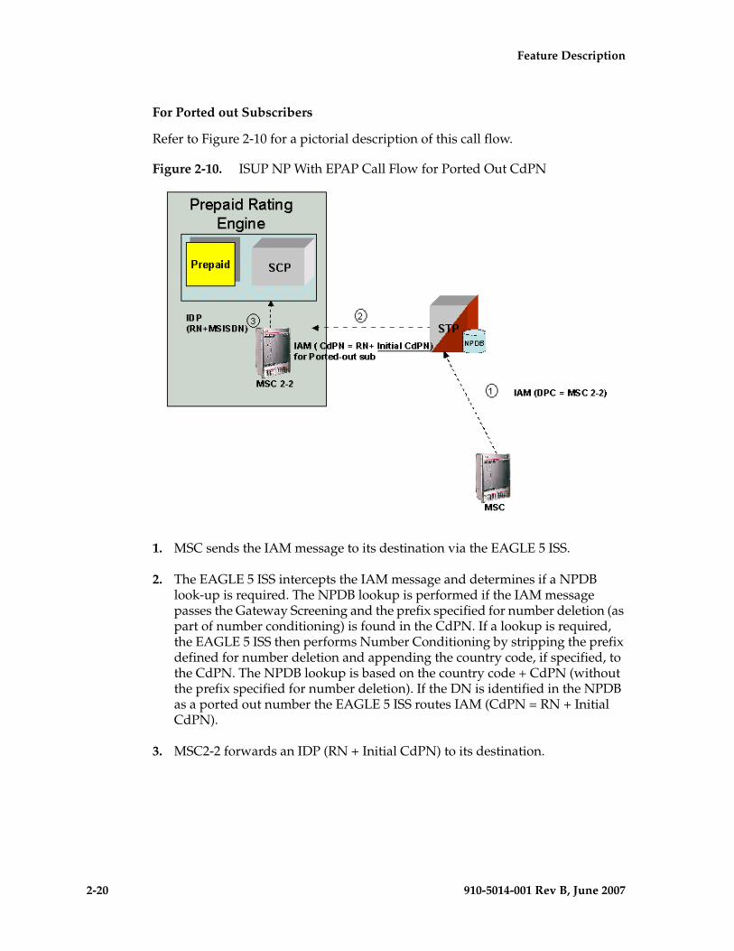
2-20 910-5014-001 Rev B, June 2007
- Prel- Draft -minary - Feature Description
For Ported out Subscribers
Refer to Figure 2-10 for a pictorial description of this call flow.
Figure 2-10. ISUP NP With EPAP Call Flow for Ported Out CdPN
1. MSC sends the IAM message to its destination via the EAGLE 5 ISS.
2. The EAGLE 5 ISS intercepts the IAM message and determines if a NPDB look-up is required. The NPDB lookup is performed if the IAM message passes the Gateway Screening and the prefix specified for number deletion (as part of number conditioning) is found in the CdPN. If a lookup is required, the EAGLE 5 ISS then performs Number Conditioning by stripping the prefix defined for number deletion and appending the country code, if specified, to the CdPN. The NPDB lookup is based on the country code + CdPN (without the prefix specified for number deletion). If the DN is identified in the NPDB as a ported out number the EAGLE 5 ISS routes IAM (CdPN = RN + Initial CdPN).
3. MSC2-2 forwards an IDP (RN + Initial CdPN) to its destination.
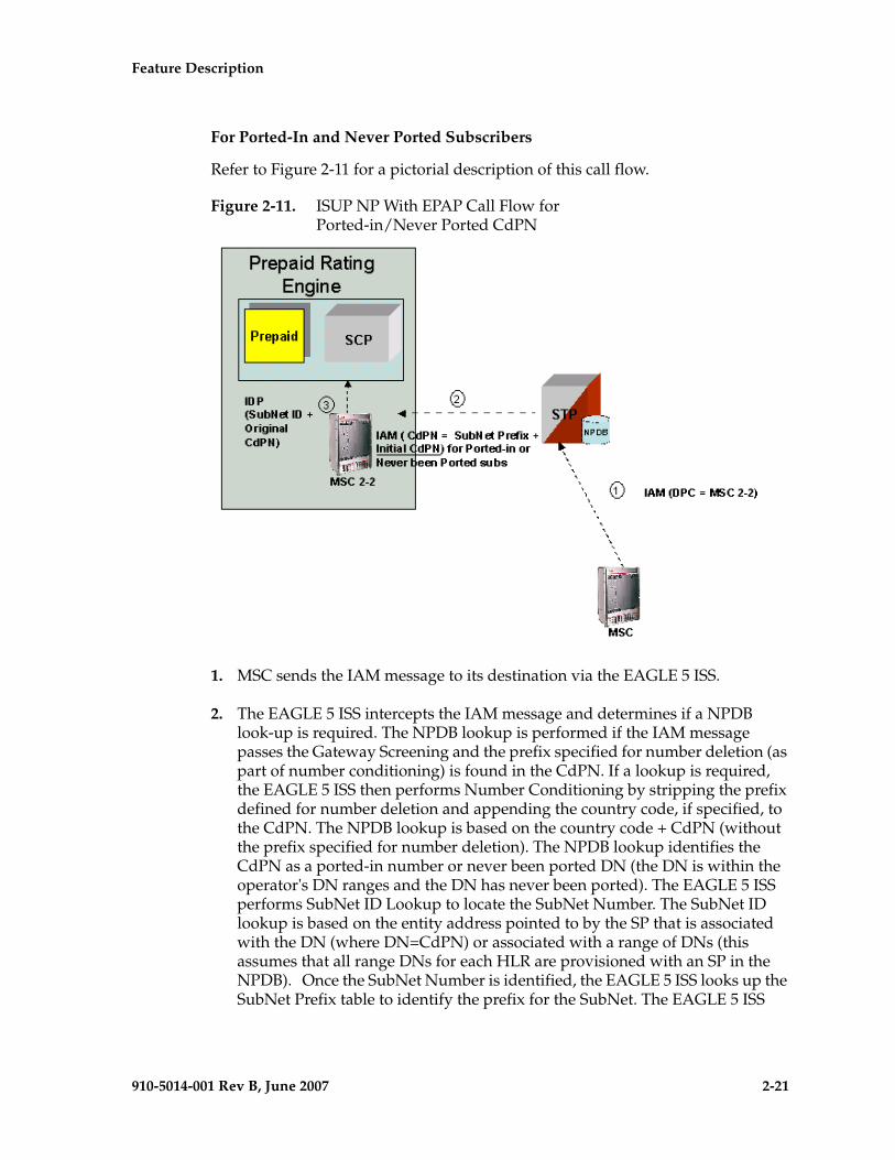
Feature Description - Prel- Draft -iminary -
910-5014-001 Rev B, June 2007 2-21
For Ported-In and Never Ported Subscribers
Refer to Figure 2-11 for a pictorial description of this call flow.
Figure 2-11. ISUP NP With EPAP Call Flow for Ported-in/Never Ported CdPN
1. MSC sends the IAM message to its destination via the EAGLE 5 ISS.
2. The EAGLE 5 ISS intercepts the IAM message and determines if a NPDB look-up is required. The NPDB lookup is performed if the IAM message passes the Gateway Screening and the prefix specified for number deletion (as part of number conditioning) is found in the CdPN. If a lookup is required, the EAGLE 5 ISS then performs Number Conditioning by stripping the prefix defined for number deletion and appending the country code, if specified, to the CdPN. The NPDB lookup is based on the country code + CdPN (without the prefix specified for number deletion). The NPDB lookup identifies the CdPN as a ported-in number or never been ported DN (the DN is within the operator's DN ranges and the DN has never been ported). The EAGLE 5 ISS performs SubNet ID Lookup to locate the SubNet Number. The SubNet ID lookup is based on the entity address pointed to by the SP that is associated with the DN (where DN=CdPN) or associated with a range of DNs (this assumes that all range DNs for each HLR are provisioned with an SP in the NPDB). Once the SubNet Number is identified, the EAGLE 5 ISS looks up the SubNet Prefix table to identify the prefix for the SubNet. The EAGLE 5 ISS
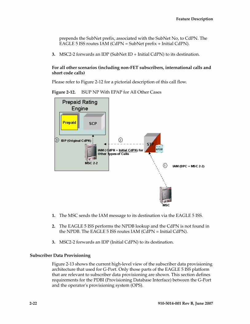
2-22 910-5014-001 Rev B, June 2007
- Prel- Draft -minary - Feature Description
prepends the SubNet prefix, associated with the SubNet No, to CdPN. The EAGLE 5 ISS routes IAM (CdPN = SubNet prefix + Initial CdPN).
3. MSC2-2 forwards an IDP (SubNet ID + Initial CdPN) to its destination.
For all other scenarios (including non-FET subscribers, international calls and short code calls)
Please refer to Figure 2-12 for a pictorial description of this call flow.
Figure 2-12. ISUP NP With EPAP for All Other Cases
1. The MSC sends the IAM message to its destination via the EAGLE 5 ISS.
2. The EAGLE 5 ISS performs the NPDB lookup and the CdPN is not found in the NPDB. The EAGLE 5 ISS routes IAM (CdPN = Initial CdPN).
3. MSC2-2 forwards an IDP (Initial CdPN) to its destination.
Subscriber Data Provisioning
Figure 2-13 shows the current high-level view of the subscriber data provisioning architecture that used for G-Port. Only those parts of the EAGLE 5 ISS platform that are relevant to subscriber data provisioning are shown. This section defines requirements for the PDBI (Provisioning Database Interface) between the G-Port and the operator's provisioning system (OPS).
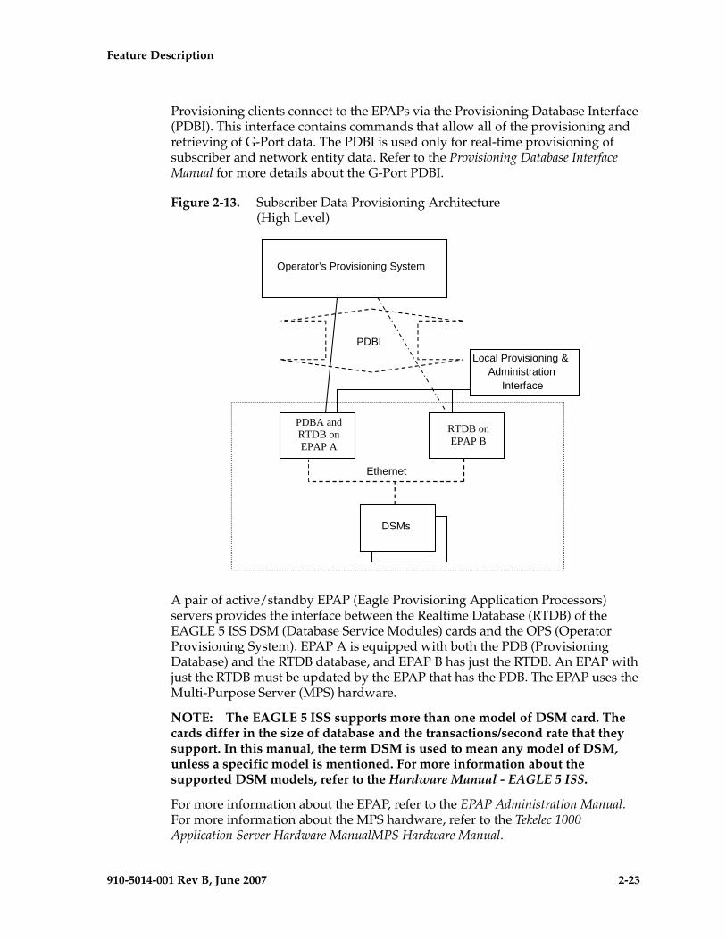
Feature Description - Prel- Draft -iminary -
910-5014-001 Rev B, June 2007 2-23
Provisioning clients connect to the EPAPs via the Provisioning Database Interface (PDBI). This interface contains commands that allow all of the provisioning and retrieving of G-Port data. The PDBI is used only for real-time provisioning of subscriber and network entity data. Refer to the Provisioning Database Interface Manual for more details about the G-Port PDBI.
Figure 2-13. Subscriber Data Provisioning Architecture (High Level)
A pair of active/standby EPAP (Eagle Provisioning Application Processors) servers provides the interface between the Realtime Database (RTDB) of the EAGLE 5 ISS DSM (Database Service Modules) cards and the OPS (Operator Provisioning System). EPAP A is equipped with both the PDB (Provisioning Database) and the RTDB database, and EPAP B has just the RTDB. An EPAP with just the RTDB must be updated by the EPAP that has the PDB. The EPAP uses the Multi-Purpose Server (MPS) hardware.
NOTE: The EAGLE 5 ISS supports more than one model of DSM card. The cards differ in the size of database and the transactions/second rate that they support. In this manual, the term DSM is used to mean any model of DSM, unless a specific model is mentioned. For more information about the supported DSM models, refer to the Hardware Manual - EAGLE 5 ISS.
For more information about the EPAP, refer to the EPAP Administration Manual. For more information about the MPS hardware, refer to the Tekelec 1000 Application Server Hardware ManualMPS Hardware Manual.
PDBI
DSMs
Ethernet
Operator’s Provisioning System
RTDB onEPAP B
Local Provisioning &Administration
Interface
PDBA andRTDB onEPAP A
2-24 910-5014-001 Rev B, June 2007
- Prel- Draft -minary - Feature Description
Database Overview
This section describes, at a high level, the distributed administrative architecture for the EAGLE 5 ISS, which includes the G-Port administrative solution.
In general, STP database updates are sent via an EAGLE 5 ISS terminal across an RS232 serial port to the active OAM (Operation Administration and Maintenance). The active OAM commits the update to TDM fixed disk and then sends the update control information to the standby OAM and to the rest of the network cards. When all databases are updated, the active OAM responds with a Command Completed indication to the user terminal. STP database updates are generally considered to be EAGLE 5 ISS link, linkset, route, destination, mated application, gateway screening, and global title types of information.
Typically, large databases requiring much faster update and retrieval rates (compared to the rates provided by the OAM) are not administered via EAGLE 5 ISS terminals. These subscriber databases, such as G-Port, are populated using redundant Ethernet connections to DSM cards from an EPAP MPS platform.
An EPAP consists of a combined Provisioning database (MySQL) and RTDB database, as shown in Figure 2-14. The PDB responds to requests for updates by the active and standby RTDB databases on both mated EAGLE 5 ISSs. The active EPAP RTDB database is responsible for initiating multicast updates of changed database records to the DSM cards after the data has been committed to the EPAP disks. Furthermore, the PDB may accept and commit to more database updates while the RTDB databases are completing their previous updates.
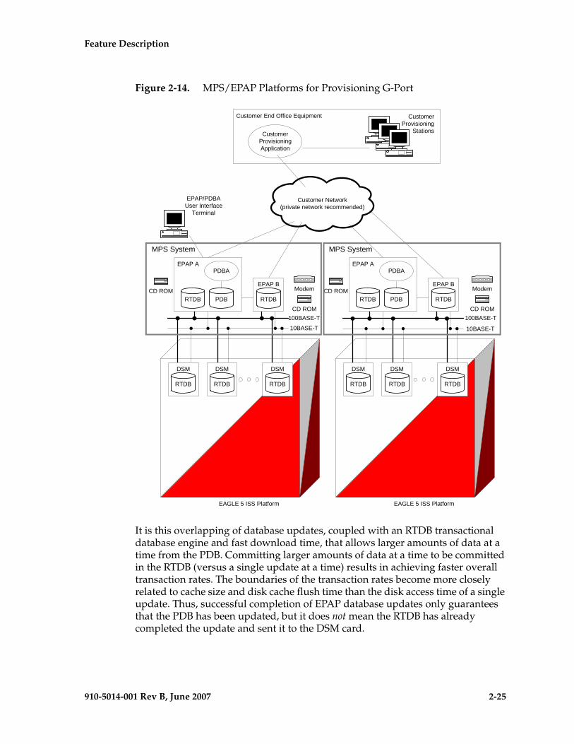
Feature Description - Prel- Draft -iminary -
910-5014-001 Rev B, June 2007 2-25
Figure 2-14. MPS/EPAP Platforms for Provisioning G-Port
It is this overlapping of database updates, coupled with an RTDB transactional database engine and fast download time, that allows larger amounts of data at a time from the PDB. Committing larger amounts of data at a time to be committed in the RTDB (versus a single update at a time) results in achieving faster overall transaction rates. The boundaries of the transaction rates become more closely related to cache size and disk cache flush time than the disk access time of a single update. Thus, successful completion of EPAP database updates only guarantees that the PDB has been updated, but it does not mean the RTDB has already completed the update and sent it to the DSM card.
EAGLE 5 ISS Platform
DSM
RTDB
DSM
RTDB
DSM
RTDB
EPAP B
RTDB
EAGLE 5 ISS Platform
DSM
RTDB
DSM
RTDB
DSM
RTDB
100BASE-T
10BASE-T
Customer End Office Equipment
Customer Provisioning Application
CD ROM
EPAP A
PDBRTDB
PDBA
EPAP B
RTDBCD ROM
EPAP A
PDBRTDB
PDBA
100BASE-T
10BASE-T
Customer Network(private network recommended)
EPAP/PDBAUser Interface
Terminal
CD ROM
Modem
CD ROM
Modem
Customer Provisioning
Stations
MPS System MPS System
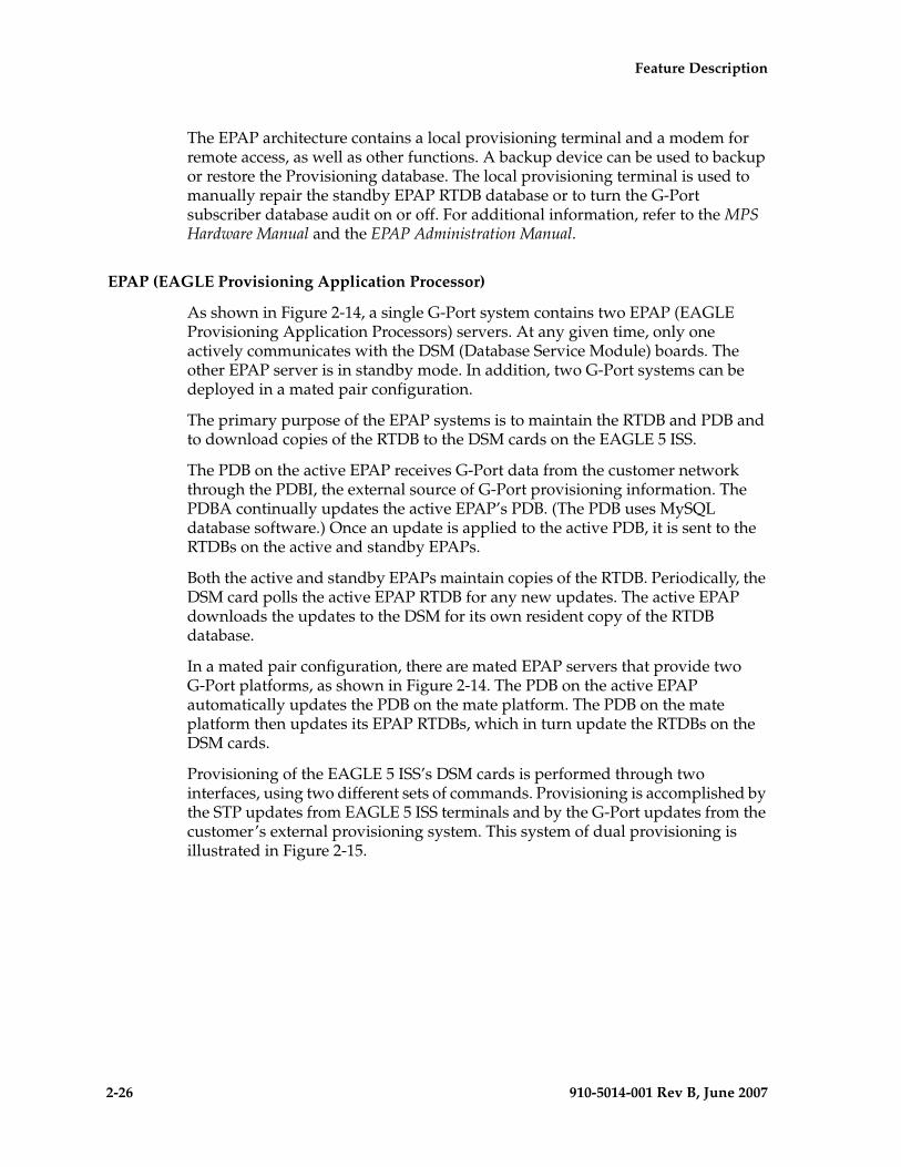
2-26 910-5014-001 Rev B, June 2007
- Prel- Draft -minary - Feature Description
The EPAP architecture contains a local provisioning terminal and a modem for remote access, as well as other functions. A backup device can be used to backup or restore the Provisioning database. The local provisioning terminal is used to manually repair the standby EPAP RTDB database or to turn the G-Port subscriber database audit on or off. For additional information, refer to the MPS Hardware Manual and the EPAP Administration Manual.
EPAP (EAGLE Provisioning Application Processor)
As shown in Figure 2-14, a single G-Port system contains two EPAP (EAGLE Provisioning Application Processors) servers. At any given time, only one actively communicates with the DSM (Database Service Module) boards. The other EPAP server is in standby mode. In addition, two G-Port systems can be deployed in a mated pair configuration.
The primary purpose of the EPAP systems is to maintain the RTDB and PDB and to download copies of the RTDB to the DSM cards on the EAGLE 5 ISS.
The PDB on the active EPAP receives G-Port data from the customer network through the PDBI, the external source of G-Port provisioning information. The PDBA continually updates the active EPAP’s PDB. (The PDB uses MySQL database software.) Once an update is applied to the active PDB, it is sent to the RTDBs on the active and standby EPAPs.
Both the active and standby EPAPs maintain copies of the RTDB. Periodically, the DSM card polls the active EPAP RTDB for any new updates. The active EPAP downloads the updates to the DSM for its own resident copy of the RTDB database.
In a mated pair configuration, there are mated EPAP servers that provide two G-Port platforms, as shown in Figure 2-14. The PDB on the active EPAP automatically updates the PDB on the mate platform. The PDB on the mate platform then updates its EPAP RTDBs, which in turn update the RTDBs on the DSM cards.
Provisioning of the EAGLE 5 ISS’s DSM cards is performed through two interfaces, using two different sets of commands. Provisioning is accomplished by the STP updates from EAGLE 5 ISS terminals and by the G-Port updates from the customer’s external provisioning system. This system of dual provisioning is illustrated in Figure 2-15.
Feature Description - Prel- Draft -iminary -
910-5014-001 Rev B, June 2007 2-27
Figure 2-15. Administrative Architecture
DSM (Database Service Module) Cards
The G-Port feature can provision from 1 to 25 DSM cards. DSM cards are related to the TSM family, but differ by having an AMD K-6 processor, from 1 to 4 GB of memory on an applique board, and two Ethernet ports. (Figure 2-14 illustrates each DSM card having two Ethernet links, the main DSM network on the 100BASE-T link and the backup DSM network on the 10BASE-T link.)
NOTE: The EAGLE 5 ISS supports more than one model of DSM card. The cards differ in the size of database and the transactions/second rate that they support. In this manual, the term DSM is used to mean any model of DSM, unless a specific model is mentioned. For more information about the supported DSM models, refer to the Hardware Manual - EAGLE 5 ISS.
The extra memoryEach DSM holds a copy of the RTDB. The DSM Ethernet ports are linked to the EPAP systems to receive the downloaded RTDBs. The DSMs run a version of the SCCP software application that has been ported to the VxWorks OS. To differentiate the DSM-VxWorks-SCCP application from the SCCP that runs on TSM cards, the DSM version is named ‘VSCCP’.
Multiple DSMs provide a means of load balancing in high-traffic situations. The DSM database is in a format that facilitates rapid lookups. Each DSM contains an identical database. Furthermore, all DSM G-Port subscriber databases are identical to the RTDB maintained by the EPAPs.
Fixed Disk
ActiveOAM
DatabaseSTP
Removable Disk
DatabaseSTP
Fixed Disk
DatabaseSTP
StandbyOAM
Interprocessor Message Transport
Ethernet Networks
DSM
STPDatabase RTDB
DB engine
(Up to 25 DSMs)
DSM
RTDB
RTDB
DB engine
ActiveEPAP
StandbyEPAP
RTDBPDB
STP Updatesfrom EagleTerminals
EPAP Sync NetworkG-Port Updates
fromCustomer's
ExternalProvisioning
System(PDBI)
2-28 910-5014-001 Rev B, June 2007
- Prel- Draft -minary - Feature Description
However, the various subscriber databases may not be identical at all times for several reasons. First of all, when a DSM card is initialized, it downloads the current copy of the subscriber database from the EPAP. While that card is being loaded, it cannot receive new updates that have arrived at the EPAP since reload began. Another condition that can result in subscriber databases being out-of-sync occurs when the EPAP receives updates from its provisioning source, but it has not yet sent them down to the DSM cards. Updates are applied to the provisioning database as they are received.
Two possible scenarios contribute to a condition where a DSM may not have enough memory to hold the entire database. In the first case, the database is downloaded successfully to the DSM, but subsequent updates eventually increase the size of the database beyond the capacity of the DSM memory. In this situation, it is desirable to continue processing G-Port transactions, even though the database may not be as up-to-date as it could be.
The other case occurs when a DSM card is booted. If it is determined then that the card does not have enough memory for the entire database, the database is not loaded on that card. Each DSM is responsible for recognizing and reporting its out-of-memory conditions by means of alarms.
Overview of EPAP to DSM Communications
Before discussing DSM status reporting or EPAP status reporting, it is helpful to understand the communications between the DSMs and the EPAP in broad terms.
• UDP - sending DSM status messages
The DSMs and EPAPs create a UDP (User Datagram Protocol) socket, which is used for status messages. One of the last things a DSM does when it is initialized is to send a status message to the EPAP, containing the DSM ID, database level, and memory size. The EPAP maintains tables containing the last known status of each DSM. EPAP uses these to determine whether or not the DSM needs to download the database.
• IP - reporting EPAP maintenance data
The DSMs create an TCP/IP socket when they are initialized, and listen for connection requests. During initialization or after a loss of connectivity, the active EPAP chooses one of the DSMs and issues a Connect to establish the TCP/IP connection with that DSM (referred to as the primary DSM). The purpose of this link is to provide a path for reporting EPAP alarms and to forward maintenance blocks to the DSM.
• IP Multicast - downloading GSM database
Because of the large size of the database and the need to download it quickly on up to 25 DSM cards, G-Port uses a technique known as IP multicasting. This technique is based on Reliable Multicast Transport Protocol-II (RMTP-II), a product of Globalcast Communications. IP multicasting downloads the RTDB and database updates to the DSMs.
Feature Description - Prel- Draft -iminary -
910-5014-001 Rev B, June 2007 2-29
The administration of IP multicasting is based on the concept of a “tree”, or stream of data, which is constantly being broadcast by the EPAP. DSMs that need to download the real time database or to receive database updates “join the tree”. DSMs can also “leave the tree”, typically when the database fills their available memory.
DSM Provisioning and Reload
One of the core functions of the EPAP is to provision the DSM cards with the G-Port database updates. In order to provide redundancy for this feature, separate RMTP channels are created on each interface from each EPAP:
• EPAP A, Link A (on the main DSM network, 100BASE-T)
• EPAP A, Link B (on the backup DSM network, 10BASE-T)
• EPAP B, Link A (on the main DSM network, 100BASE-T)
• EPAP B, Link B (on the backup DSM network, 10BASE-T)
Provisioning and other data is broadcast on one of these channels to all of the DSM cards. Provisioning is done by database level in order to leave DSM tables coherent between updates.
The DSM cards do the following:
• Detect the need for incremental updates and send a status message to the EPAP.
• Discriminate between the various streams by the database level contained in each message and accept updates according to the DSMs current database level.
DSM Reloading Model
EPAP Continuous Reload
It is important to understand how the EPAP handles reloading of multiple DSMs from different starting points. Reload begins when the first DSM requires it. Records are read sequentially from the real-time database from an arbitrary starting point, wrapping back to the beginning. If another DSM requires reloading at this time, it uses the existing record stream and notifies the DSM provisioning task of the first record it read. This continues until all DSMs are satisfied.
2-30 910-5014-001 Rev B, June 2007
- Prel- Draft -minary - Feature Description
DSM Database Levels and Reloading
The current database level when the reload started is of special importance during reload. When a DSM detects that the last record has been received, it sends a status message back to the EPAP indicating the database level at the start of reload. This action starts incremental loading. The DSM continues to reload until it is completely caught up with the current level of the RTDB. As database records are sent to the DSMs during reload, normal provisioning can change those records. All records changed between the start and end of reloading must be incrementally loaded before the database is coherent and usable by the DSM.
The following terminology is used here for the stages of database reload for a given DSM.
• Stage 1 loading: The database is being copied record for record from the golden RTDB to the DSM RTDB. The database is incoherent during stage 1 loading.
• Incremental update: The database is receiving all of the updates missed during stage 1 loading or some other reason (e.g., network outage, processor limitation, lost communication, etc.). The database is coherent but back level during incremental update.
• Current: The database is receiving current updates from the DSM provisioning task.
• Coherent: The database is at a whole database level, that is, not currently updating records belonging to a database level.
DSM Reload Requirements
DSM cards may require a complete database reload if there is a reboot or loss of connectivity for a significant amount of time. The EPAP provides a mechanism to quickly load a number of DSM cards with the current database. The RTDB on the EPAP is large and can be updated constantly from the customer’s provisioning network.
The upload process is divided into two stages, one to sequentially send the initial database records and another to send any updates missed since the beginning of the first stage. The DSM reload stream uses a separate RMTP channel from the provisioning and incremental update streams. This allows DSM multicast hardware to filter out the high volume of reload traffic from DSM cards that do not require it.
DSM cards do the following:
• Detect the need for stage 1 loading and send a status message to the EPAP.
• Identify the first record DSM was able to read in the above status message if a record stream is already in progress.
Feature Description - Prel- Draft -iminary -
910-5014-001 Rev B, June 2007 2-31
• Handle the record stream regardless of the starting point (that is, records starting with the middle record of the middle table).
• Expect tables to be sent in a particular order and therefore detect any gap in the record stream.
• Send a status message if a gap is detected. Stage 1 loading is essentially reset to the last update received.
• Handle wrapping from the last record from the last table to the first record of the first table.
• Know when they have received all the required records to proceed to stage 2 loading.
• Send a status message when stage 1 loading is complete, indicating the database level at the beginning of stage 1.
• Detect when the master RTDB crosses a memory boundary during stage 1 loading; the card automatically reboots and then auto-inhibits.
EPAP Status and Error Reporting via Maintenance Blocks
The EPAPs forward all status and error messages to the DSMs in maintenance blocks. Maintenance blocks are asynchronously sent whenever the EPAP has something to report. The maintenance blocks eventually update EPAP device control blocks (DCBs) located on the EAGLE 5 ISS. The DCBs provide the status information you receive when you issue a rept-stat-mps command.
Network Connections
Several customer- and Tekelec-installed private networks are required to support the G-Port feature. These networks are:
• Customer provisioning network
• EPAP sync network
• DSM networks
• Dial-up network
The following discussion is an overview of these private networks. It expands on the networks in the G-Port architecture diagram shown in Figure 2-14, on page 2-25. (For details about configuring these networks, refer to the EPAP Administration Manual.)
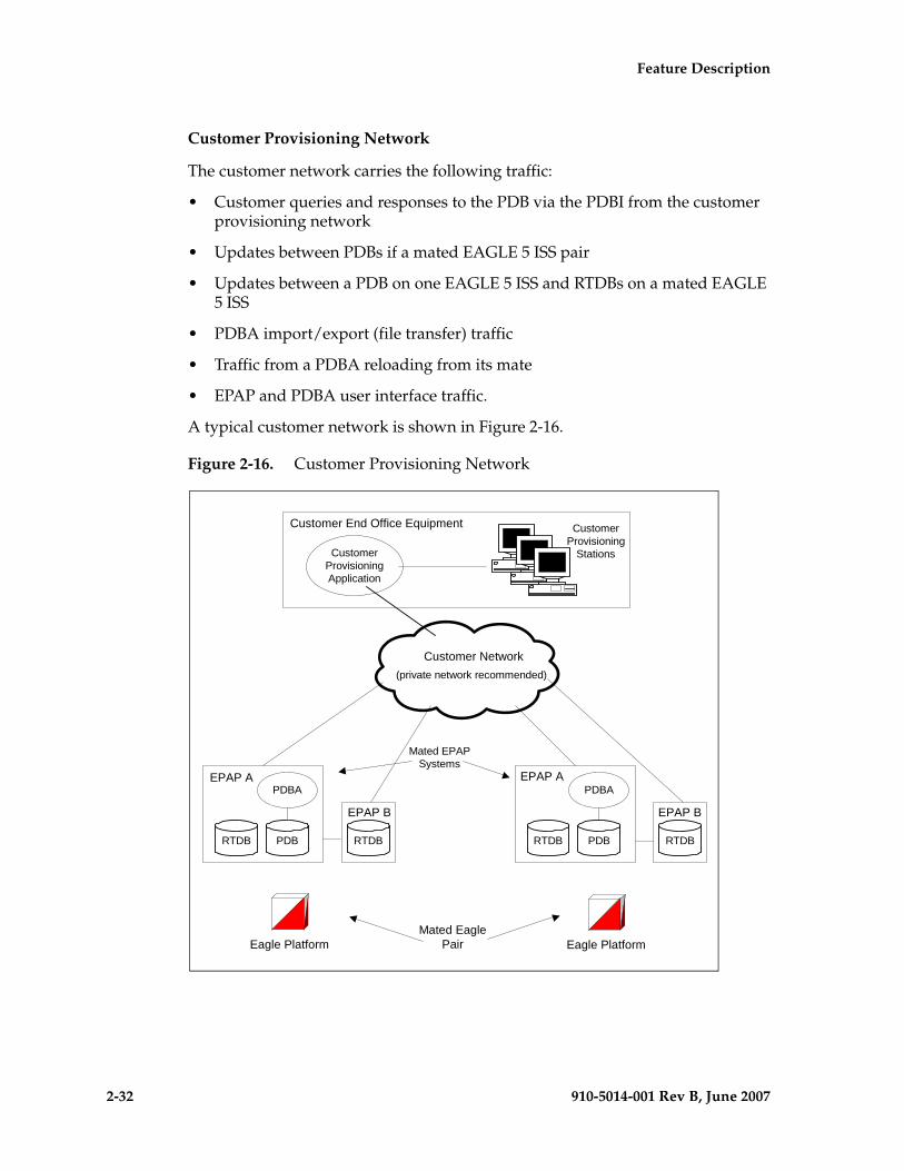
2-32 910-5014-001 Rev B, June 2007
- Prel- Draft -minary - Feature Description
Customer Provisioning Network
The customer network carries the following traffic:
• Customer queries and responses to the PDB via the PDBI from the customer provisioning network
• Updates between PDBs if a mated EAGLE 5 ISS pair
• Updates between a PDB on one EAGLE 5 ISS and RTDBs on a mated EAGLE 5 ISS
• PDBA import/export (file transfer) traffic
• Traffic from a PDBA reloading from its mate
• EPAP and PDBA user interface traffic.
A typical customer network is shown in Figure 2-16.
Figure 2-16. Customer Provisioning Network
RTDB
EPAP A
PDBRTDB
PDBA
RTDBPDBRTDB
PDBA
Customer Network(private network recommended)
EPAP A
EPAP B EPAP B
Customer End Office Equipment
CustomerProvisioningApplication
CustomerProvisioning
Stations
Mated EPAPSystems
Eagle Platform Eagle PlatformMated Eagle
Pair
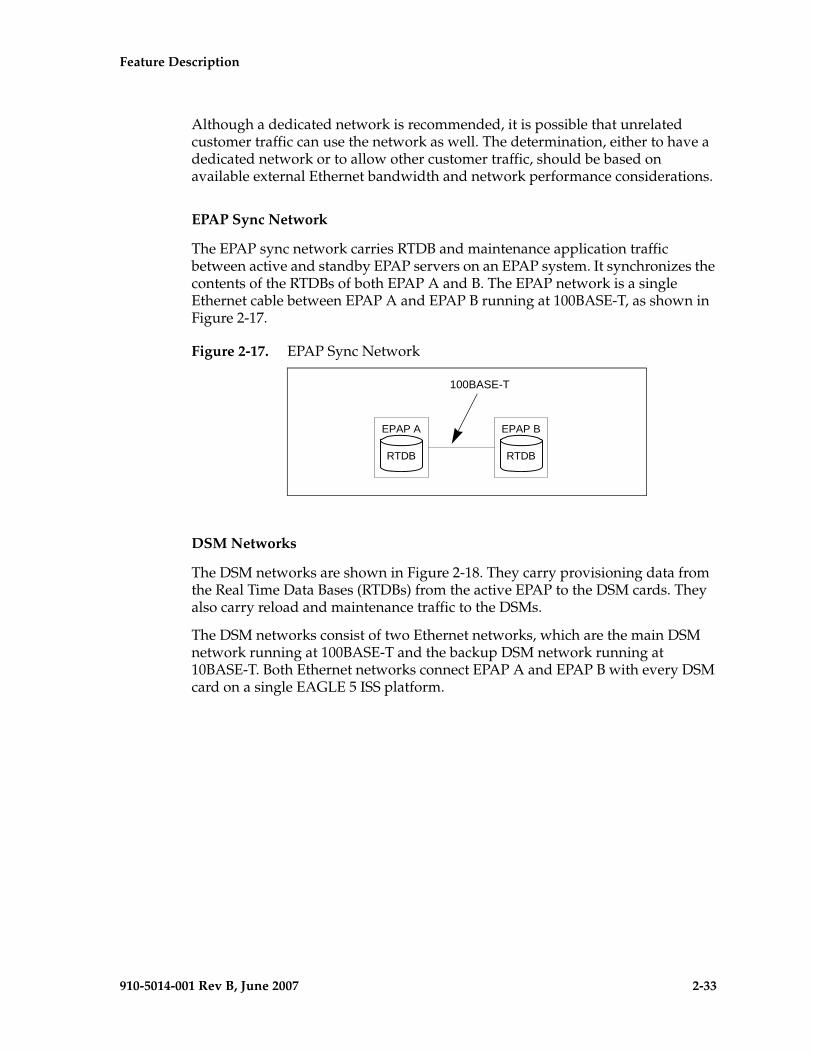
Feature Description - Prel- Draft -iminary -
910-5014-001 Rev B, June 2007 2-33
Although a dedicated network is recommended, it is possible that unrelated customer traffic can use the network as well. The determination, either to have a dedicated network or to allow other customer traffic, should be based on available external Ethernet bandwidth and network performance considerations.
EPAP Sync Network
The EPAP sync network carries RTDB and maintenance application traffic between active and standby EPAP servers on an EPAP system. It synchronizes the contents of the RTDBs of both EPAP A and B. The EPAP network is a single Ethernet cable between EPAP A and EPAP B running at 100BASE-T, as shown in Figure 2-17.
Figure 2-17. EPAP Sync Network
DSM Networks
The DSM networks are shown in Figure 2-18. They carry provisioning data from the Real Time Data Bases (RTDBs) from the active EPAP to the DSM cards. They also carry reload and maintenance traffic to the DSMs.
The DSM networks consist of two Ethernet networks, which are the main DSM network running at 100BASE-T and the backup DSM network running at 10BASE-T. Both Ethernet networks connect EPAP A and EPAP B with every DSM card on a single EAGLE 5 ISS platform.
EPAP A
RTDB
EPAP B
RTDB
100BASE-T
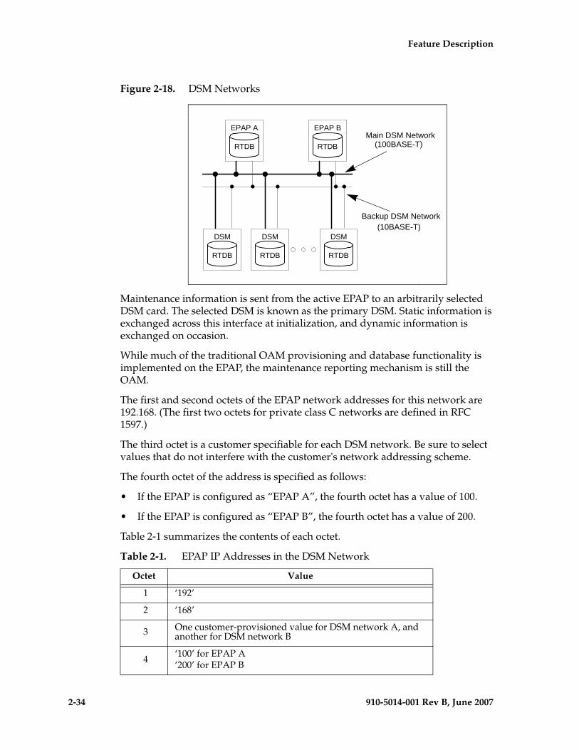
2-34 910-5014-001 Rev B, June 2007
- Prel- Draft -minary - Feature Description
Figure 2-18. DSM Networks
Maintenance information is sent from the active EPAP to an arbitrarily selected DSM card. The selected DSM is known as the primary DSM. Static information is exchanged across this interface at initialization, and dynamic information is exchanged on occasion.
While much of the traditional OAM provisioning and database functionality is implemented on the EPAP, the maintenance reporting mechanism is still the OAM.
The first and second octets of the EPAP network addresses for this network are 192.168. (The first two octets for private class C networks are defined in RFC 1597.)
The third octet is a customer specifiable for each DSM network. Be sure to select values that do not interfere with the customer's network addressing scheme.
The fourth octet of the address is specified as follows:
• If the EPAP is configured as “EPAP A”, the fourth octet has a value of 100.
• If the EPAP is configured as “EPAP B”, the fourth octet has a value of 200.
Table 2-1 summarizes the contents of each octet.
Table 2-1. EPAP IP Addresses in the DSM Network
Octet Value
1 ‘192’
2 ‘168’
3 One customer-provisioned value for DSM network A, and another for DSM network B
4 ‘100’ for EPAP A‘200’ for EPAP B
DSM
RTDB
DSM
RTDB
DSM
RTDB
EPAP A
RTDB
EPAP B
RTDB
DSM network A
DSM network B
Main DSM Network (100BASE-T)
Backup DSM Network (10BASE-T)
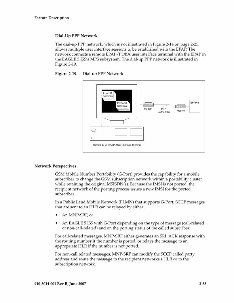
Feature Description - Prel- Draft -iminary -
910-5014-001 Rev B, June 2007 2-35
Dial-Up PPP Network
The dial-up PPP network, which is not illustrated in Figure 2-14 on page 2-25, allows multiple user interface sessions to be established with the EPAP. The network connects a remote EPAP/PDBA user interface terminal with the EPAP in the EAGLE 5 ISS’s MPS subsystem. The dial-up PPP network is illustrated in Figure 2-19.
Figure 2-19. Dial-up PPP Network
Network Perspectives
GSM Mobile Number Portability (G-Port) provides the capability for a mobile subscriber to change the GSM subscription network within a portability cluster while retaining the original MSISDN(s). Because the IMSI is not ported, the recipient network of the porting process issues a new IMSI for the ported subscriber.
In a Public Land Mobile Network (PLMN) that supports G-Port, SCCP messages that are sent to an HLR can be relayed by either:
• An MNP-SRF, or
• An EAGLE 5 ISS with G-Port depending on the type of message (call-related or non-call-related) and on the porting status of the called subscriber.
For call-related messages, MNP-SRF either generates an SRI_ACK response with the routing number if the number is ported, or relays the message to an appropriate HLR if the number is not ported.
For non-call related messages, MNP-SRF can modify the SCCP called party address and route the message to the recipient networks's HLR or to the subscription network.
EPAP B
Remote EPAP/PDBA User Interface Terminal
PPPConnection
EPAP UISessions
EPAP UISessions
EPAP UISessions
PDBA UISessions
PDBA UISessions
PDBA UISessions
ModemModem
2-36 910-5014-001 Rev B, June 2007
- Prel- Draft -minary - Feature Description
Figure 2-20 shows the location of the G-Port in a GSM network. Note the basic functions G-Port performs:
• G-Port performs a query/response for call-related SRI messages when the number is ported-out or not known to be ported.
• G-Port performs a message relay function for non-call-related messages and, for call-related messages when the number is non-ported or ported-in.
G-Port performs the following actions based on the message received and number status:
• If the number is ported-out or not known to be ported and the message received is call-related SRI (not-SOR), G-Port sends the SRI ack to the MSC with the Routing Number information in the MAP portion of the message.
• If the number is ported-out and the message received is non-call related (non-SRI), G-Port performs a message relay function and forwards the translated message based on the Routing Number information.
• If the number is non-ported or ported-in and the message received, G-Port performs an HLR translation and forwards the translated message to the HLR.
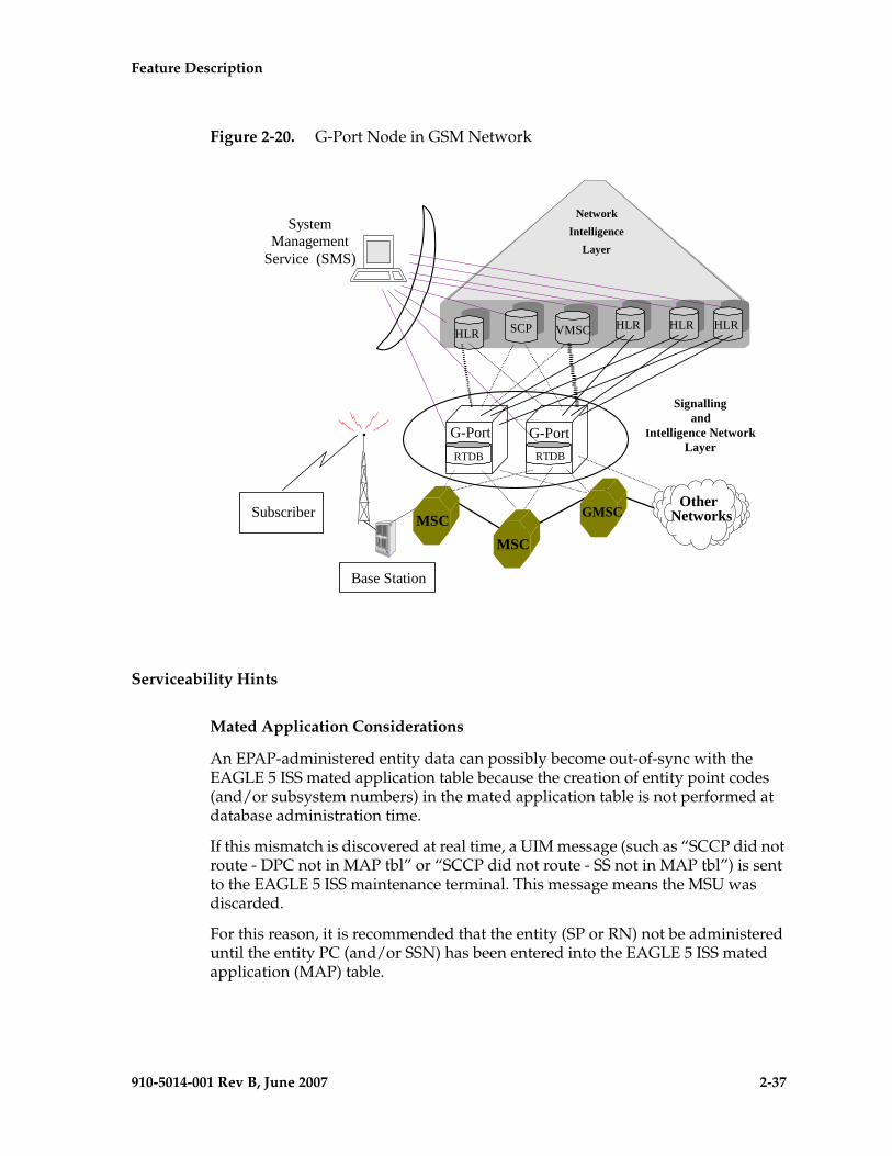
Feature Description - Prel- Draft -iminary -
910-5014-001 Rev B, June 2007 2-37
Figure 2-20. G-Port Node in GSM Network
Serviceability Hints
Mated Application Considerations
An EPAP-administered entity data can possibly become out-of-sync with the EAGLE 5 ISS mated application table because the creation of entity point codes (and/or subsystem numbers) in the mated application table is not performed at database administration time.
If this mismatch is discovered at real time, a UIM message (such as “SCCP did not route - DPC not in MAP tbl” or “SCCP did not route - SS not in MAP tbl”) is sent to the EAGLE 5 ISS maintenance terminal. This message means the MSU was discarded.
For this reason, it is recommended that the entity (SP or RN) not be administered until the entity PC (and/or SSN) has been entered into the EAGLE 5 ISS mated application (MAP) table.
MSC
MSCMSC
GMSC
G-PortRTDB
HLR
SCPSCP SMS
CVMSC HLR HLR HLRHLR
SystemManagement
Service (SMS)
Subscriber
Base Station
RTDB
G-Port
OtherNetworks
NetworkIntelligence
Layer
Signallingand
Intelligence NetworkLayer
2-38 910-5014-001 Rev B, June 2007
- Prel- Draft -minary - Feature Description
Entity Point Codes and Routes
Verification that an entity point code exists in the route table and has a route is not performed at database administration time. Therefore, it is possible for the EPAP entity data to be out-of-sync with the EAGLE 5 ISS route table.
If an out-of-sync condition is discovered at real time, a UIM is sent to the EAGLE 5 ISS maintenance terminal, indicating one of these conditions:
• Destination point code is not in the route table.
• Destination point code exists in the route table but is not assigned a route.
• Destination point code exists in the route table and has been assigned a route, but it is out of service.
G-Port Considerations
The following list contains considerations you should think over before installing and operating the G-Port feature.
1. SRI responses are routed by both MTP and Global Title Translation.
2. The maximum length of the Application Context Name Object Identifier is 32 digits.
3. For G-Port Message Relay messages with E.164 numbers in the SCCP CDPA, it is assumed that no truncation occurred if and when the routing number was prepended and that SCCP CDPA has the full DN of the subscriber.
4. G-Port Message Relay to the EAGLE 5 ISS local subsystem is not supported.
5. Only the first 21 digits of the CDPA are decoded for G-Port Message Relay. For example, if the CDPA contains an RN prefixed to a DN, the RN is seven digits, and the DN is 15 digits, then the total is 22 digits, and the DN used for processing will be only 14 digits (21 total digits less 7 RN digits).
6. GTT currently handles decimal digits only. Thus, if an operator/country is using hexadecimal digits ‘A’ through ‘F’ in RNs and the operator is providing GTT to messages that have RN prefixes other than its own prefixes, the operator must enter the RN + DN number ranges as DN ranges in the G-Port database. The only problem with this is that the beginning and ending DNs can only be 15 digits, which may not be enough for an RN + DN.
7. As discussed in this document, MNP applies within a single portability cluster. This is defined as a set of networks in a country or multi-country region having a common numbering plan and across which a subscriber, who is already inside the cluster, can port. Any individual G-Port node is required to support only an MNP within such a portability cluster.
Feature Description - Prel- Draft -iminary -
910-5014-001 Rev B, June 2007 2-39
8. The EAGLE 5 ISS examines the TCAP portion of the MAP message to determine the message type. Although GSM 03.66 defines a new translation type for SRI-MNP messages, G-Port MNP does not rely upon the use of this TT.
9. The routing number found in the NP database is either prefixed to the dialed number to form a new concatenated roaming number that is returned to the switch, or is sent on its own as the roaming number.
10. No MAP overload procedures, as defined in GSM 09.02, need to be supported by G-Port MNP.
11. All non-call related messages impacted by MNP contain the MSISDN number in the SCCP CdPA. In the case of the SRI message, G-Port may get the number from the MAP level.
12. TCAP operation codes uniquely distinguish MAP SRI messages and do not change from one phase (or version) of MAP to another.
13. PCs and/or PC + SSNs that are in the entity table of the database and referenced by subscriber entries do not necessarily have the required data present on the EAGLE 5 ISS to route messages to them. For example, the point code may not have a route or the PC + SSN may not be in the MAP table for a final GTT. In this event, a UIM is output only when a message is discarded because of the lack of data.
14. The parameters of the SRI ack message generated by G-Port are solely based on the provisioned data/options; they are not based on the MAP phase of the SRI message. For example, if the message received is phase 1 or 2, “MSRNDIG=RN”, and the portability status is “NotKnowntobePorted”, G-Port generates an SRI ack contains IMSI, MSRN, MSISDN, and NPS parameters, despite the MSISDN and NPS parameters not being defined for phase 1 or 2.
15. If SRFIMSI is not provisioned with an RN entity and an incoming message is an SRI message, G-Port sets IMSI parameter as zero digits when the MAP phase is 1 or 2.
16. G-Port uses the MTP route for the SRI ack response, even when the final GTT is performed on the response.
17. When the concatenated number (RN + MSISDN) option is selected for encoding the Routing Info (MSRN) in SRI ack, G-Port encodes the complete concatenated number, because the concatenated number length may otherwise exceed 16 digits, which is the maximum allowed in MSRN.

2-40 910-5014-001 Rev B, June 2007
- Prel- Draft -minary - Feature Description
General Requirements
Numbering
• Incoming called party numbers (from the SCCP portion) destined for G-Port processing are conditioned to fit the GDB requirements where possible:
– If the GTT selectors available in the incoming message match an entry in the G-Port selector table, then the service numbering plan from the selector table entry uses that number's numbering plan. Further conditioning is applied based on this new numbering plan.
– If the GTT selectors available in the incoming message match an entry in the G-Port selector table, then the service nature of address from the selector table entry uses that number's nature of address. Further conditioning is applied based on this new nature of address.
– If the nature of address is Subscriber, the default CC + default NC (network code for E.164) are prepended to the number. The default codes to be used by the EAGLE 5 ISS must be previously provisioned by the EAGLE 5 ISS operator. If not, a UIM is issued, and the message falls through to GTT.
• Numbers with fewer than five digits after the above conditioning are not used for G-Port. In this case, a UIM is issued, and the message falls through to GTT.
• Numbers with more than 15 digits after the above conditioning are not used for G-Port. In this case, a UIM is issued, and the message falls through to GTT.
Maintenance
Validation of G-Port Hardware Configuration
DSM card loading has been modified to verify the validity of the hardware configuration for the DSM cards. Hardware verification includes the following.
• DSM Main Board Verification
An AMD-K6 (or better) main board is required to support the G-Port VSCCP application on the DSM card. EAGLE 5 ISS maintenance stores the validity status of the VSCCP card's main board configuration. NOTE: The system does not allow the G-Port feature to be enabled if the hardware configuration is invalid.
When the VSCCP application is initializing, it determines the main board type. The SCCP maintenance block is the mechanism used to relay the main board information to OAM. This requires that the application software be loaded to the VSCCP card and then the main board information received in the SCCP maintenance block must be verified. If the main board is determined to be invalid for the G-Port application, loading of the VSCCP card is automatically inhibited.
Feature Description - Prel- Draft -iminary -
910-5014-001 Rev B, June 2007 2-41
• DSM Applique Memory Verification
The VSCCP application performs two types of memory validation to determine whether or not a DSM has sufficient memory to run G-Port:
CAUTION: The G-Port feature access key (FAK) cannot be enabled if any of the DSMs have less than 1 GB of memory installed. Refer to the Dimensioning Guide for EPAP Advanced DB Features Technical Reference for important information on the dimensioning rules and the DSM database capacity requirements.
• Local Memory Validation. When the G-Port FAK is first enabled, or any time the G-Port feature is enabled and the DSM is initializing, VSCCP checks to see if the DSM has at least one D1G applique.
• Real-Time Memory Validation (during card initialization). Once communications between the DSM and EPAP have been established, and the DSM has joined the RMTP Tree, the EPAP starts downloading the RTDB to the DSM card. After the DSM card has downloaded the RTDB, it continues to receive database updates as necessary. The EPAP includes the size of the current RTDB in all records sent to the DSM. The DSM card compares the size required to the amount of memory installed, and issues a minor alarm once the database exceeds 80% of the DSM memory. If the database completely fills the DSM memory, a major alarm is issued, the DSM leaves the RMTP tree, and the DSM's status changes to IS-ANR/Restricted. The DSM continues to carry traffic.
• Actions Taken When Hardware Determined to be Invalid
When the hardware configuration for a DSM card is determined to be invalid for the G-Port application, SCM automatically inhibits loading for that specific DSM card. A major alarm is generated indicating that card loading for that DSM card has failed and has been automatically inhibited (that is, prevented from reloading again). Refer to Chapter 5, G-Port Related Alarms, page 5-12, for the specific alarm that is generated. When card loading has been inhibited, the primary state of the card is set to oos-mt-dsbld, and the secondary state of the card is set to MEA (Mismatch of Equipment and Attributes).
The following actions apply to a DSM card determined to be invalid:
• The DSM will not download the EAGLE 5 ISS databases.
• The DSM will not download the real-time RTDB from the EPAP.
• The DSM will not accept RTDB updates (that is, add, change, delete) from the EPAP, nor will it accept STP database updates.
To activate loading of a DSM card that has been automatically inhibited, the craftsperson must enter the alw-card command (alw-card:loc=xxxx).
2-42 910-5014-001 Rev B, June 2007
- Prel- Draft -minary - Feature Description
• Unstable Loading Mode
At some point, having a number of invalid DSM cards results in some of the LIMs (Link Interface Module) being denied SCCP services. There is a threshold that needs to be monitored: if the number of valid DSMs is insufficient to provide service to at least 80% of the IS-NR LIMs, the system is said to be in an unstable loading mode. For other reasons why an EAGLE 5 ISS might be in an unstable loading mode, refer to Chapter 5, Loading Mode Support Status Reporting, page 5-5.
Maintenance Commands
The following commands are used for G-Port maintenance.
• The debug command ent-trace traps G-Port MSUs (Message Signaling Unit) based on the point code of the switch that generated the MSU (SSP), a particular DN and entity ID. Note that a MSU is considered to be a G-Port MSU after its CdPA SSN is determined to be a HLR SSN. For MSISDN and entity ID, the comparison is based on the search key built from the CdPA GTAI (Global Title Address Information) after any conditioning. The existing GT SCCP trigger also applies to G-Port messages.
• The command rept-stat-mps reports current G-Port statistics. A MSU is considered to be a G-Port MSU after its CdPA SSN is determined to be a HLR SSN. This command reports G-Port statistics on a single SCCP card basis or on a G-Port system basis.
For more information, refer to Chapter 5, Maintenance and Measurements, page 5-1.
G-Port Loading Mode Support
Loading mode support is not applicable for RTDB updates, since DSM cards use incremental loading from the EPAP. STP Administrative updates are allowed while a DSM card is loading and the system is above the 80% card stability threshold. If it is below the 80% threshold, loading mode support allows STP administrative updates to be rejected while cards finish loading and cross the 80% or better threshold.
For G-Port, loading mode support is applicable for database updates originating from the EAGLE 5 ISS GPSM-II’s (General Purpose Service Module II cards) destined for the DSM cards.
Audit Requirements
The G-Port audit does not change EAGLE 5 ISS's compliance to STP audit requirements, to which it currently adheres. New G-Port database tables residing on the EAGLE 5 ISS TDM fixed disks are audited by the existing STP audit, which only verifies tables on the EAGLE 5 ISS active and standby TDMs. There are new audit mechanisms for new G-Port tables residing on the EPAP platform that are downloaded to the DSM cards. The new audit mechanisms consist of the following.
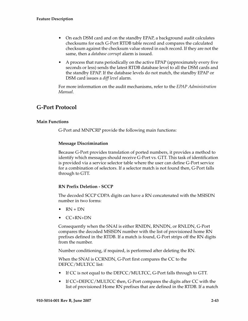
Feature Description - Prel- Draft -iminary -
910-5014-001 Rev B, June 2007 2-43
• On each DSM card and on the standby EPAP, a background audit calculates checksums for each G-Port RTDB table record and compares the calculated checksum against the checksum value stored in each record. If they are not the same, then a database corrupt alarm is issued.
• A process that runs periodically on the active EPAP (approximately every five seconds or less) sends the latest RTDB database level to all the DSM cards and the standby EPAP. If the database levels do not match, the standby EPAP or DSM card issues a diff level alarm.
For more information on the audit mechanisms, refer to the EPAP Administration Manual.
G-Port Protocol
Main Functions
G-Port and MNPCRP provide the following main functions:
Message Discrimination
Because G-Port provides translation of ported numbers, it provides a method to identify which messages should receive G-Port vs. GTT. This task of identification is provided via a service selector table where the user can define G-Port service for a combination of selectors. If a selector match is not found then, G-Port falls through to GTT.
RN Prefix Deletion - SCCP
The decoded SCCP CDPA digits can have a RN concatenated with the MSISDN number in two forms:
• RN + DN
• CC+RN+DN
Consequently when the SNAI is either RNIDN, RNNDN, or RNLDN, G-Port compares the decoded MSISDN number with the list of provisioned home RN prefixes defined in the RTDB. If a match is found, G-Port strips off the RN digits from the number.
Number conditioning, if required, is performed after deleting the RN.
When the SNAI is CCRNDN, G-Port first compares the CC to the DEFCC/MULTCC list:
• If CC is not equal to the DEFCC/MULTCC, G-Port falls through to GTT.
• If CC=DEFCC/MULTCC then, G-Port compares the digits after CC with the list of provisioned Home RN prefixes that are defined in the RTDB. If a match
2-44 910-5014-001 Rev B, June 2007
- Prel- Draft -minary - Feature Description
is found, then G-Port strips off the RN digits from the number. If no match is found, the no-prefix deletion is performed and G-Port processing continues.
RN Prefix Deletion - TCAP
The decoded MAP MSISDN digits can have a RN concatenated with the MSISDN number in two forms:
• RN + DN
• CC+RN+DN
The MAP NAI is used to determine the type: International, National or Subscriber. If MNPCRP is OFF, RN prefix deletion is not attempted. If MNPCRP is ON, then RN prefix deletion is attempted on all MSISDNs. If the MAP NAI indicates International, then a check is performed for the DEFCC/MULTCC prefix on the MSISDN. If DEFCC/MULTCC is detected, then HomeRN deletion is attempted using the CC+RN+DN format. All other MSISDNs will use the RN+DN format. G-Port compares the decoded MSISDN number with the list of provisioned home RN prefixes defined in the RTDB. If a match is found, the G-Port strips off the RN digits from the number.
Number conditioning (if required) is performed after deleting the RN.
If CC+RN+DN search is performed, G-Port compare the digits after CC with the list of provisioned home RN prefixes defined in the RTDB. If a match is found, G-Port strips off the RN digits from the number. If no match is found, then no prefix deletion is performed and G-Port processing continues.
Number Conditioning
The RTDB stores international MSISDNs only. The received MSISDN number or SCCP CDPA digits may need to be converted to an international number to do a database lookup.
When G-Port is required to be performed on a message and the number is not international (that is, the NAI of MSISDN number is “National (Significant) Number” or “Subscriber Number”, or the SNAI is NATL or SUB or RNNDN or RNLDN), the National/Local to International number is triggered.
For a National (Significant) Number, the received CDPA/MAP MSISDN digits are prepended with the default country code; for a Subscriber number, the CDPA/MAP MSISDN digits are prepended with the default country code and the default network code.
Feature Description - Prel- Draft -iminary -
910-5014-001 Rev B, June 2007 2-45
Database Lookup
G-Port performs the RTDB database lookup using the international MSISDN.
The individual number database is searched first:
• If the number is not found, the number range database is searched.
• If a match is not found in the individual and range-based database, the GTT is performed on the message.
In the event of the MSISDN numbers in the RTDB database being odd and CDPA GTI of the incoming message being ‘2’, and the last digit of the number is 'zero':
• G-Port first performs database lookup one time using the even number.
• If no match is found, G-Port again performs the database lookup, using the odd number (without last digit).
Since a DN may be the target of the A-Port, G-Port, or Migration message processing in a hybrid network (where an operator owns both GSM and IS41 network), message processing call disposition is based on what applications are turned on. Table 2-2 through Table 2-2 show call dispositions for the following configurations:
G-Port Only (Table 2-2)
G-Port and IGM (Table 2-3)
The following notations apply to Table 2-2 and Table 2-3.
PT = Portability Type for the DN
Values: 0 – not known to be ported
1 – own number ported out
2 – foreign number ported to foreign network
3 – prepaid 1 (used by PPSMS)
4 – prepaid 2 (used by PPSMS)
5 – migrated with one handset
RN = Routing Number
SOR = Support for Optimal Routing
SRI = Send Routing Information
SP = Signaling Point
NE = Network Entity
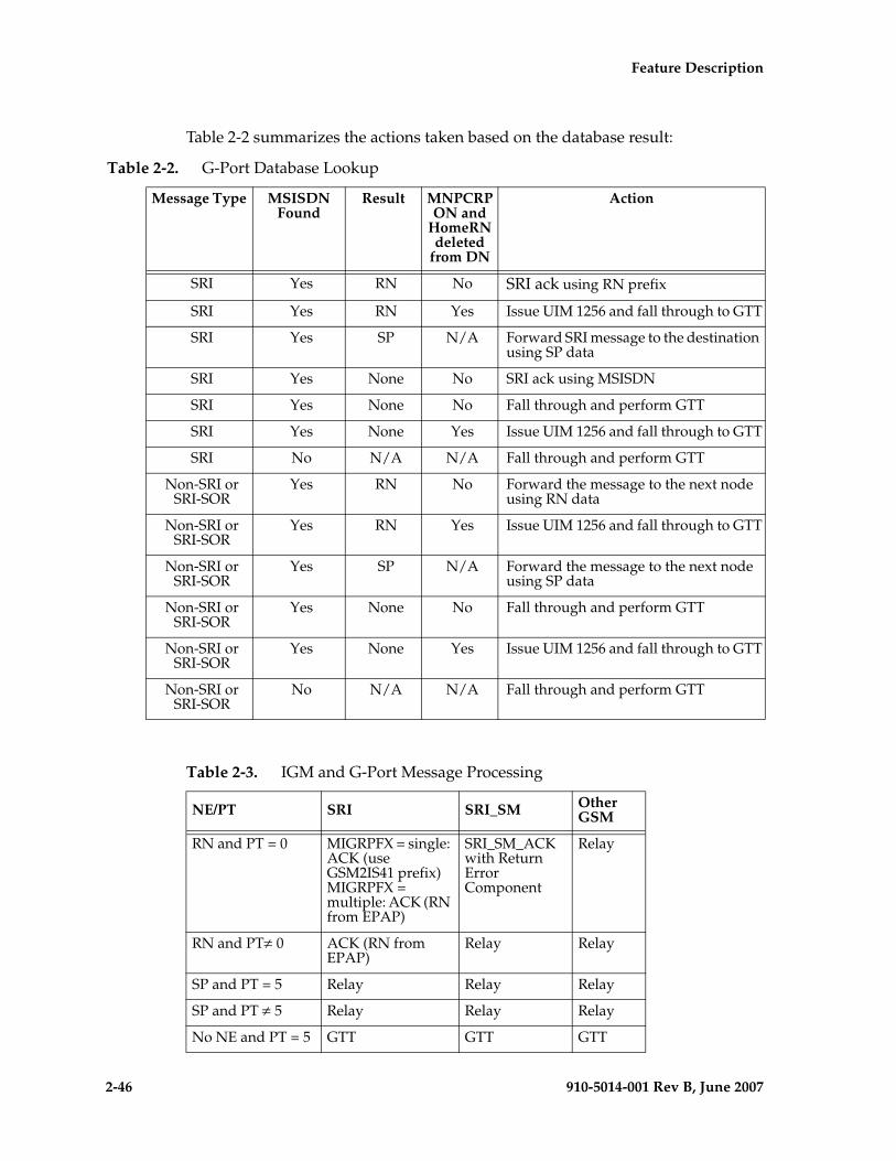
2-46 910-5014-001 Rev B, June 2007
- Prel- Draft -minary - Feature Description
Table 2-2 summarizes the actions taken based on the database result:
Table 2-2. G-Port Database Lookup
Message Type MSISDN Found
Result MNPCRP ON and
HomeRN deleted
from DN
Action
SRI Yes RN No SRI ack using RN prefix
SRI Yes RN Yes Issue UIM 1256 and fall through to GTT
SRI Yes SP N/A Forward SRI message to the destination using SP data
SRI Yes None No SRI ack using MSISDN
SRI Yes None No Fall through and perform GTT
SRI Yes None Yes Issue UIM 1256 and fall through to GTT
SRI No N/A N/A Fall through and perform GTT
Non-SRI or SRI-SOR
Yes RN No Forward the message to the next node using RN data
Non-SRI or SRI-SOR
Yes RN Yes Issue UIM 1256 and fall through to GTT
Non-SRI or SRI-SOR
Yes SP N/A Forward the message to the next node using SP data
Non-SRI or SRI-SOR
Yes None No Fall through and perform GTT
Non-SRI or SRI-SOR
Yes None Yes Issue UIM 1256 and fall through to GTT
Non-SRI or SRI-SOR
No N/A N/A Fall through and perform GTT
Table 2-3. IGM and G-Port Message Processing
NE/PT SRI SRI_SM Other GSM
RN and PT = 0 MIGRPFX = single: ACK (use GSM2IS41 prefix) MIGRPFX = multiple: ACK (RN from EPAP)
SRI_SM_ACK with Return Error Component
Relay
RN and PT≠ 0 ACK (RN from EPAP)
Relay Relay
SP and PT = 5 Relay Relay Relay
SP and PT ≠ 5 Relay Relay Relay
No NE and PT = 5 GTT GTT GTT
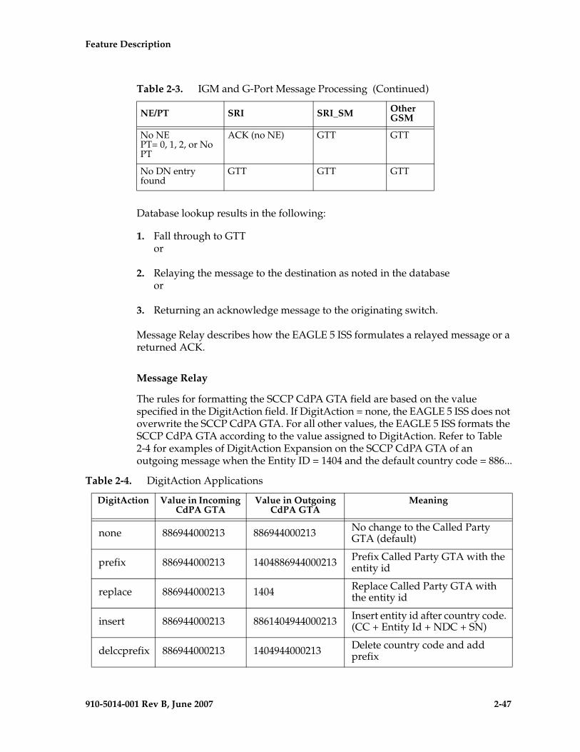
Feature Description - Prel- Draft -iminary -
910-5014-001 Rev B, June 2007 2-47
Database lookup results in the following:
1. Fall through to GTTor
2. Relaying the message to the destination as noted in the databaseor
3. Returning an acknowledge message to the originating switch.
Message Relay describes how the EAGLE 5 ISS formulates a relayed message or a returned ACK.
Message Relay
The rules for formatting the SCCP CdPA GTA field are based on the value specified in the DigitAction field. If DigitAction = none, the EAGLE 5 ISS does not overwrite the SCCP CdPA GTA. For all other values, the EAGLE 5 ISS formats the SCCP CdPA GTA according to the value assigned to DigitAction. Refer to Table 2-4 for examples of DigitAction Expansion on the SCCP CdPA GTA of an outgoing message when the Entity ID = 1404 and the default country code = 886...
No NEPT= 0, 1, 2, or No PT
ACK (no NE) GTT GTT
No DN entry found
GTT GTT GTT
Table 2-3. IGM and G-Port Message Processing (Continued)
NE/PT SRI SRI_SM Other GSM
Table 2-4. DigitAction Applications
DigitAction Value in Incoming CdPA GTA
Value in Outgoing CdPA GTA
Meaning
none 886944000213 886944000213 No change to the Called Party GTA (default)
prefix 886944000213 1404886944000213 Prefix Called Party GTA with the entity id
replace 886944000213 1404 Replace Called Party GTA with the entity id
insert 886944000213 8861404944000213 Insert entity id after country code. (CC + Entity Id + NDC + SN)
delccprefix 886944000213 1404944000213 Delete country code and add prefix
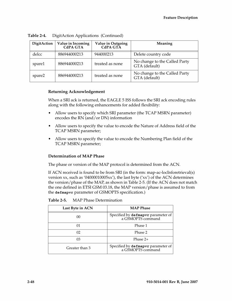
2-48 910-5014-001 Rev B, June 2007
- Prel- Draft -minary - Feature Description
Returning Acknowledgement
When a SRI ack is returned, the EAGLE 5 ISS follows the SRI ack encoding rules along with the following enhancements for added flexibility:
• Allow users to specify which SRI parameter (the TCAP MSRN parameter) encodes the RN (and/or DN) information
• Allow users to specify the value to encode the Nature of Address field of the TCAP MSRN parameter;
• Allow users to specify the value to encode the Numbering Plan field of the TCAP MSRN parameter;
Determination of MAP Phase
The phase or version of the MAP protocol is determined from the ACN.
If ACN received is found to be from SRI (in the form: map-ac-locInforetrieval(s) version xx, such as ‘04000010005xx’), the last byte (‘xx’) of the ACN determines the version/phase of the MAP, as shown in Table 2-5. (If the ACN does not match the one defined in ETSI GSM 03.18, the MAP version/phase is assumed to from the defmapvr parameter of GSMOPTS specification.)
delcc 886944000213 944000213 Delete country code
spare1 886944000213 treated as none No change to the Called Party GTA (default)
spare2 886944000213 treated as none No change to the Called Party GTA (default)
Table 2-4. DigitAction Applications (Continued)
DigitAction Value in Incoming CdPA GTA
Value in Outgoing CdPA GTA
Meaning
Table 2-5. MAP Phase Determination
Last Byte in ACN MAP Phase
00 Specified by defmapvr parameter of a GSMOPTS command
01 Phase 1
02 Phase 2
03 Phase 2+
Greater than 3 Specified by defmapvr parameter of a GSMOPTS command
Feature Description - Prel- Draft -iminary -
910-5014-001 Rev B, June 2007 2-49
G-Port Message Handling
G-Port performs message handling in the following steps.
1. The message arrives at the EAGLE 5 ISS route-on-gt. The EAGLE 5 ISS decodes the SCCP portion and uses the data to perform the G-Port selection based on the CDPA GT fields other than the ES and GTAI. The result of the selection provides a service indicator. The service indicator is G-Port if it is determined that MNP-SRF is required. If a G-Port selector does not match the incoming GT fields, the message is passed on for GTT selection.
2. MNP-SRF first decodes the Operation Code of the MAP message to distinguish the SRI message from the rest. If the Operation Code is SRI and the OR Interrogation indicator is absent, and the GSMOPTS parameter SRIDN=TCAP, the MSISDN parameter is decoded from the MAP message. If the GSMOPTS parameter SRIDN=SCCP, or the message is not SRI, the digits available in the CDPA GTAI are used for database lookup.
3. The decoded DN is conditioned to an international number before performing the RTDB lookup. The conditioning performed depends on whether the digits are obtained from TCAP or MAP part of the message.
• If the digits are from the SCCP part, the number conditioning is based on SNAI value. First, RN prefix deletion is performed, and conversion to an international number, based on its value. Conversion to international format is based on DEFCC and DEFNDC, as required. If the incoming number is CCRNDN, DEFCC and MULTCC are used to determine the Best Match CC to locate the RN digits for RN prefix deletion
• If the digits are from the MAP part, the number conditioning is based on NAI of MSISDN parameter. Prefix deletion is performed if MNPCRP is ON. The number is converted to an international number, if necessary. Conversion to international format is based on DEFCC and DEFNDC, as required. If the incoming number is international, DEFCC and MULTCC are used to determine if the format is CCRNDN or RNIDN. If a Best Match CC is located, then it is used to locate the RN digits for RN prefix deletion.
4. The RTDB database lookup is performed in two parts:
• The exception or individual number database is searched for a match. If the match is found, the data associated with this entry is considered.
• If the conditioned number is absent in the exception database, the number range database is searched. If the match is found, the data associated with this range entry is considered. If the search is unsuccessful, the result is no match.
5. If the number is found and a RN prefix is present for this entry, the following is performed:
2-50 910-5014-001 Rev B, June 2007
- Prel- Draft -minary - Feature Description
• If the message is SRI, and MNPCRP is OFF, or if MNPCRP is ON and a HomeRN was not present in the incoming DN (a HomeRN was not deleted from the SCCP CdPA/MAP MSISDN), then G-Port generates a SRI ack response with the RN prefix in the Routing Number parameter.
• If the message is non-SRI, and MNPCRP is OFF, or if MNPCRP is ON and a HomeRN was not present in the incoming DN a HomeRN was not deleted from the SCCP CdPA), then G-Port uses the translation data for the number to alter the CdPA digits and route the message to the destination.
• If the message is SRI or non-SRI, and MNPCRP is ON, and a HomeRN was present in the incoming DN (a HomeRN was deleted from the SCCP CdPA/MAP MSISDN), then G-Port generates UIM #1256, and the message shall fall through to GTT. In most network implementations, since the message contains RN+DN, this should cause a GTT failure, which will result in the EAGLE 5 ISS sending a UDTS to the originator if the Return Message on Error flag was set in the incoming UDT.
6. If the number is found and a SP entity is present for this entry, G-Port uses the SP translation data as the number to route the message to the destination. This is true whether or not MNPCRP feature is ON.
7. If the number is found and neither SP nor RN data is associated with it (this is a direct routing case with number not known to be ported), the following occurs:
• If the message is SRI, and MNPCRP is OFF, or if MNPCRP is ON and no HomeRN is present in the incoming DN (a HomeRN was not deleted from the SCCP CdPA/MAP MSISDN), and if the portability type associated with the DN entry is other than 3 or 4 (including "no status"), then G-Port generates a SRI ack response with the MSISDN in the Routing Number parameter. If the message is SRI, and MNPCRP is OFF, or if MNPCRP is ON and no HomeRN was present in the incoming DN (a HomeRN was not deleted from the SCCP CdPA/MAP MSISDN), and the portability type associated with the DN entry is either 3 or 4, then the SRI falls through to GTT (no SRI ack response is generated).
• If the message is non-SRI, and MNPCRP is OFF, or if MNPCRP is ON and no HomeRN is present in the incoming DN (a HomeRN was not deleted from the SCCP CdPA), then the message falls through to GTT.
Feature Description - Prel- Draft -iminary -
910-5014-001 Rev B, June 2007 2-51
• If the message is SRI or non-SRI, and MNPCRP is ON, and a HomeRN was present in the incoming DN (a HomeRN was deleted from the SCCP CdPA/MAP MSISDN), then G-Port generates UIM #1256, and the message falls through to GTT. In most network implementations, since the message contains RN+DN, this should cause a GTT failure, which results in the EAGLE 5 ISS sending a UDTS to the originator if the Return Message on Error flag was set in the incoming UDT.
8. GTT is performed on the message for any of these conditions:
• If G-Port is not required, or
• If the number is not found in the RTDB (both range and exception database).
G-Port SCCP Service Re-Route Capability
This feature is designed to handle and control re-routing of G-Port traffic from an affected node to alternate nodes within an operators network. This feature is an optional feature and doesn't affect the normal G-Port functionality. This feature consists to the following main functions:
• Service State
• MNP Re-Routing
• MNP Capability Point Codes
G-Port SCCP Service Re-Route Capability is not supported for the Prepaid SMS Intercept feature. G-Port SCCP Service Re-Route Capability is supported for the IS-41 to GSM Migration feature.
Service State
Service state is part of the G-Port SCCP Service Re-Route Capability. Service state is used to indicate the current state of G-Port, either ONLINE or OFFLINE. Service state also gives the user the option to mark G-Port as OFFLINE or ONLINE based on the current behavior. If a G-Port problem is identified, G-Port can be marked OFFLINE to initiate the re-routing procedure. In the case when SCCP cards need to be reloaded for some reason, G-Port can be marked OFFLINE until enough cards are in-service and then bring G-Port ONLINE in a controlled fashion. This feature also provides the option to mark G-Port OFFLINE to perform a controlled re-routing during this state.
MNP Re-Routing
MNP Re-Routing is an optional feature and is enabled by defining a list of alternate PCs or by defining the GTT option. G-Port re-routing is activated by marking G-Port OFFLINE. When G-Port is OFFLINE and alternate PCs are provisioned, any messages destined for G-Port are re-routed to the available
2-52 910-5014-001 Rev B, June 2007
- Prel- Draft -minary - Feature Description
alternate PCs that are defined for G-Port. If alternate PCs are not provisioned or none are available, then the GTT option is used. If the GTT option is set to YES, then messages destined for G-Port will fall through to GTT as part of the re-routing procedure.
Re-Routing is applied to all G-Port messages (based on SRVSEL). There is no distinction of DPC of the messages. The DPC of the message can be either True, Secondary, or Capability Point code.
MNP Capability Point Codes
Capability Point Codes (CPC) are also supported for G-Port. The use ofMNP capability point code aids the adjacent nodes in knowing about G-Port outages. When G-Port is brought down though administrative commands, all traffic destined to this G-Port node will generate a Transfer Prohibited (TFP) message to the adjacent node about the G-Port CPC. The TFP response to the adjacent node causes the traffic originating nodes to stop sending G-Port traffic to this node. All G-Port traffic coming into this node is sent to the alternate G-Port nodes. Adjacent nodes will initiate route-set-test procedures after receipt of the TFP response.
If the messages are destined to the EAGLE 5 ISS true point code, then TFP messages are not generated when the G-Port service is OFFLINE. The originator would not be aware of the outage.
Once G-Port is back in service on the EAGLE 5 ISS, a Transfer Allowed (TFA) message is sent to the traffic adjacent nodes in response to route-set-test message. The traffic originating nodes will then start sending G-Port traffic to the original G-Port node.
MNP Capability point codes can be provisioned when the G-Port feature is ON. There can be more than one Capability Point Code assigned to G-Port CPCType.
When the G-Port feature is turned ON and the G-Port service state is set to OFFLINE, the user can change the service to ONLINE at any point. Once the feature is turned ONLINE, G-Port will start processing messages if at least one SCCP card is IS-NR.
The G-Port service can be set to OFFLINE at any point. This causes the EAGLE 5 ISS to stop processing G-Port traffic and re-routing is performed.
The G-Port service state is persistent. Booting the OAM or all the SCCP cards will not change the service state. Commands must be used to change the service state.
G-Port supports up to 7 alternate PCs per domain. All 6 domains (ANSI, ITU-I, ITUN14, ITUN14 spare, ITU-I spare and ITUN24) are supported. An entire set of alternate PCs are considered as a re-route set. A GTT option is supported for G-Port re-route. When the G-Port service is OFFLINE, G-Port messages fall though to GTT based on the GTT option. This option is set to YES by default.
Feature Description - Prel- Draft -iminary -
910-5014-001 Rev B, June 2007 2-53
G-Port SCCP Service Re-Route Capability Summary
If the G-Port service is not normal (because the RTDB is not in sync with MPS or if cards are misrouting G-Port messages) then the G-Port service state should be changed to OFFLINE.
Before changing G-Port service to OFFLINE, it should be decided what kind of re-routing will be used during the outage. The EAGLE 5 ISS supports re-routing data to alternate point codes or falling through to GTT as two possible options. Rerouting to alternate point code has priority over falling though to GTT. Examples of the two options follow:
Option 1
Define alternate point codes to re-route G-Port traffic. This is the recommended option. Up to 7 alternate G-Port nodes can be provisioned to re-route all the incoming G-Port traffic. Once provisioned, the G-Port service can be changed to OFFLINE.This example has any incoming being G-Port traffic being load-shared to point codes based on the relative cost.
chg-sccp-serv:serv=gport:pci1=1-1-1:rc1=10:pci2=2-2-2:rc2=10:pci3=3-3-3:rc3=10:pci4=4-4-4:rc4=10
chg-sccp-serv:serv=gport:pci1=5-5-5:rc1=10:pci2=6-6-6:rc2=10:pci3=7-7-7:rc3=10:pci4=8-8-8:rc4=10
chg-sccp-serv:serv=gport:state=offline
Option 2
With this option default GTT translations are provisioned for G-Port service. Then the chg-sccp-serv command is used to provision GTT=YES. All G-Port messages will fall through to GTT. An example command follows:
chg-sccp-serv:serv=gport:gtt=yes (it is yes by default)
Once the G-Port re-routing data is provisioned, G-Port service can be changed to OFFLINE. At this point all G-Port traffic will be re-routed. The use can take necessary steps to correct the G-Port service on the node. Until all the cards or enough cards are in active state with valid G-Port database, G-Port service should not be changed to ONLINE.
Table 2-6 shows the actions taken when the G-Port service is offline, a message arrives at the affected node requiring G-Port service, and SCCP cards are available.
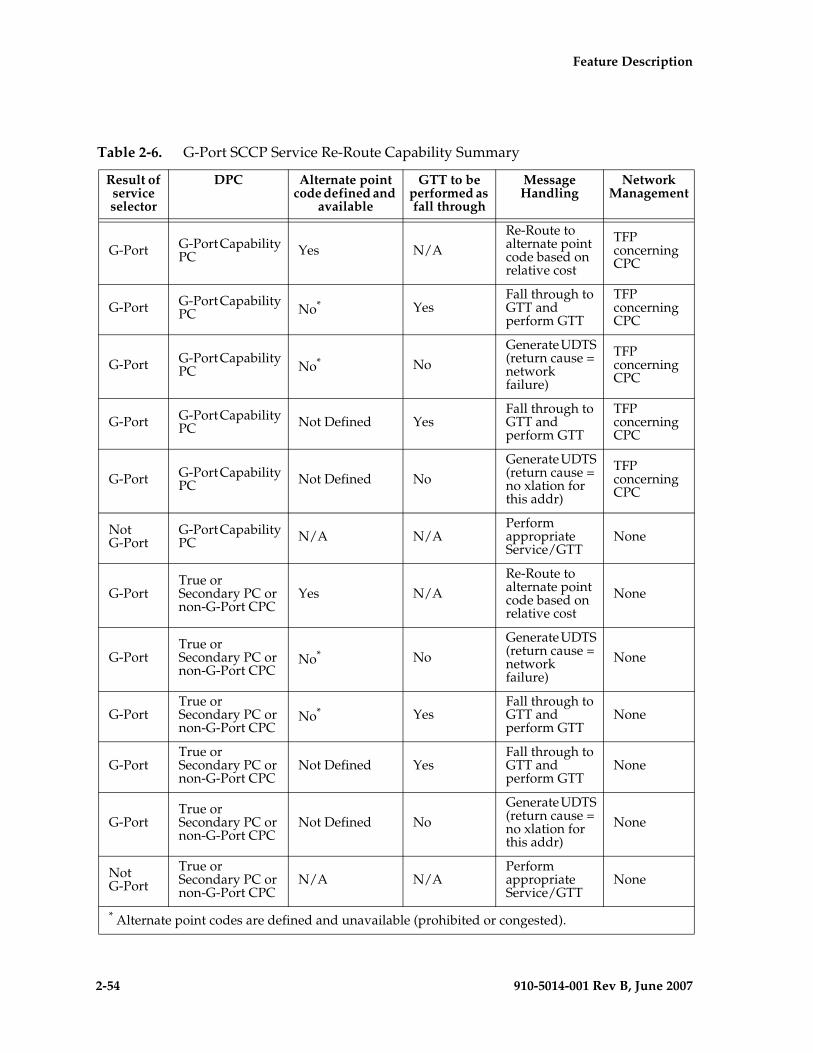
2-54 910-5014-001 Rev B, June 2007
- Prel- Draft -minary - Feature Description
Table 2-6. G-Port SCCP Service Re-Route Capability Summary
Result of service selector
DPC Alternate point code defined and
available
GTT to be performed as fall through
Message Handling
Network Management
G-Port G-Port Capability PC Yes N/A
Re-Route to alternate point code based on relative cost
TFP concerning CPC
G-Port G-Port Capability PC No* Yes
Fall through to GTT and perform GTT
TFP concerning CPC
G-Port G-Port Capability PC No* No
Generate UDTS (return cause = network failure)
TFP concerning CPC
G-Port G-Port Capability PC Not Defined Yes
Fall through to GTT and perform GTT
TFP concerning CPC
G-Port G-Port Capability PC Not Defined No
Generate UDTS (return cause = no xlation for this addr)
TFP concerning CPC
Not G-Port
G-Port Capability PC N/A N/A
Perform appropriate Service/GTT
None
G-PortTrue or Secondary PC or non-G-Port CPC
Yes N/ARe-Route to alternate point code based on relative cost
None
G-PortTrue or Secondary PC or non-G-Port CPC
No* NoGenerate UDTS (return cause = network failure)
None
G-PortTrue or Secondary PC or non-G-Port CPC
No* YesFall through to GTT and perform GTT
None
G-PortTrue or Secondary PC or non-G-Port CPC
Not Defined YesFall through to GTT and perform GTT
None
G-PortTrue or Secondary PC or non-G-Port CPC
Not Defined NoGenerate UDTS (return cause = no xlation for this addr)
None
Not G-Port
True or Secondary PC or non-G-Port CPC
N/A N/APerform appropriate Service/GTT
None
* Alternate point codes are defined and unavailable (prohibited or congested).
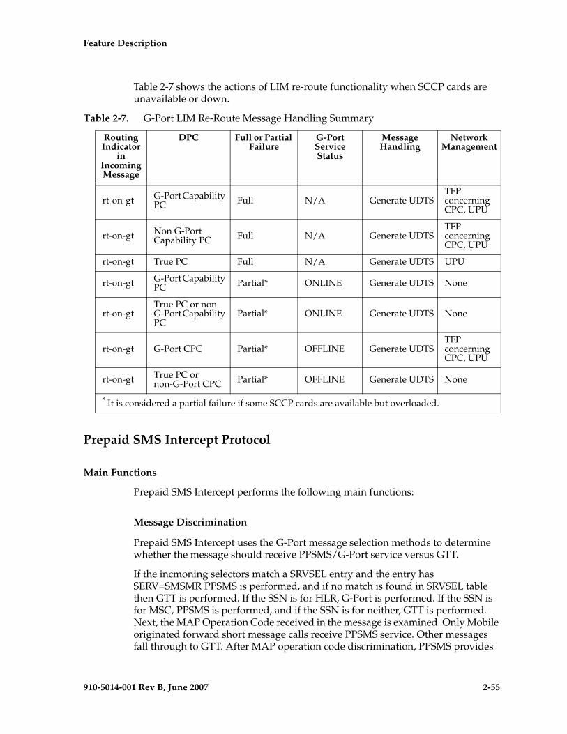
Feature Description - Prel- Draft -iminary -
910-5014-001 Rev B, June 2007 2-55
Table 2-7 shows the actions of LIM re-route functionality when SCCP cards are unavailable or down.
Prepaid SMS Intercept Protocol
Main Functions
Prepaid SMS Intercept performs the following main functions:
Message Discrimination
Prepaid SMS Intercept uses the G-Port message selection methods to determine whether the message should receive PPSMS/G-Port service versus GTT.
If the incmoning selectors match a SRVSEL entry and the entry has SERV=SMSMR PPSMS is performed, and if no match is found in SRVSEL table then GTT is performed. If the SSN is for HLR, G-Port is performed. If the SSN is for MSC, PPSMS is performed, and if the SSN is for neither, GTT is performed. Next, the MAP Operation Code received in the message is examined. Only Mobile originated forward short message calls receive PPSMS service. Other messages fall through to GTT. After MAP operation code discrimination, PPSMS provides
Table 2-7. G-Port LIM Re-Route Message Handling Summary
Routing Indicator
in Incoming Message
DPC Full or Partial Failure
G-Port Service Status
Message Handling
Network Management
rt-on-gt G-Port Capability PC Full N/A Generate UDTS
TFP concerning CPC, UPU
rt-on-gt Non G-Port Capability PC Full N/A Generate UDTS
TFP concerning CPC, UPU
rt-on-gt True PC Full N/A Generate UDTS UPU
rt-on-gt G-Port Capability PC Partial* ONLINE Generate UDTS None
rt-on-gtTrue PC or non G-Port Capability PC
Partial* ONLINE Generate UDTS None
rt-on-gt G-Port CPC Partial* OFFLINE Generate UDTSTFP concerning CPC, UPU
rt-on-gt True PC or non-G-Port CPC Partial* OFFLINE Generate UDTS None
* It is considered a partial failure if some SCCP cards are available but overloaded.
2-56 910-5014-001 Rev B, June 2007
- Prel- Draft -minary - Feature Description
discrimination based on SCCP CGPA GTA digits. This allows the operator to decide whether messages from certain CGPAs will receive PPSMS service or fall through to GTT, even if they meet all of the previous service selection criteria.
Number Conditioning
The RTDB stores international MSISDNs only. The received MSISDN number or SCCP CDPA digits may need to be converted to an international number to do a database lookup.
When PPSMS is required to be performed on a message and the number is not international (that is, the NAI of MSISDN number is “National (Significant) Number” or “Subscriber Number)”, the National/Local to International number is triggered.
For a National (Significant) Number, the received MSISDN digits are prepended with the default country code and for a Subscriber number, the MSISDN digits are prepended with the default country code and the default network code. If the NAI is neither International or Subscriber, the message is treated as National.
Prepaid Screening
Once the number is conditioned, the PPSMS feature performs a database search to determine if the MSISDN belongs to a prepaid subscriber. This is determined by the pt field associated with the database entry for the MSISDN. PPSMS performs the database lookup using the international MSISDN. The individual number database is searched first, and if the number is not found, then the number range database is searched. If a match is not found in individual nor range-based database, then GTT is performed on the message. In case of MSISDN numbers in the PPSMS database being odd and the last digit of the decoded MSISDN from the FSM being 'zero', PPSMS first performs a database lookup once using the even number. If no match is found, then PPSMS performs the database lookup again, now using the odd number (without last digit).
Message Relay to IN Platform
If the database search determines that the subscriber is prepaid, the message is redirected to one of the two IN platforms using the translation data in the GSM options table. If the routing indicator in the IN platform translation data is route-on-SSN, the mated application table is accessed to determine the point code/subsystem status for the IN platform, and if it has a mate. The SCCP CDPA GTA should not be changed as a result of this operation. If the RI in the translation data indicates route-on-GT, and if the Intermediate GTT Load Sharing feature is turned on, the mated relay node table is accessed to determine the point code status and if the IN platform has a mate. Subsystem status is not maintained in the mated relay node.
Feature Description - Prel- Draft -iminary -
910-5014-001 Rev B, June 2007 2-57
SMS Prepaid Intercept Message Handling
PPSMS performs message handling in the following steps.
1. The message arrives at the EAGLE 5 ISS route-on-gt. The EAGLE 5 ISS decodes the SCCP portion and uses the data to perform the G-Port selection based on the CDPA NP, NAI, TT, SSN, and GTI. The result of the selection provides a service indicator. The service indicator is SMSMR if PPSMS is required. If a SMSMR selector does not match the incoming GT fields, the message is passed on for GTT selection.
2. If Step 1 indicates PPSMS is required, and the message is not a UDTS generated by EAGLE 5 ISS, the EAGLE 5 ISS performs PPSMS service.
3. If the message is a UDTS generated by the EAGLE 5 ISS, then regular GTT is performed on the message.
4. If the EAGLE 5 ISS receives a UDTS message from another node, it is treated in the same manner as any other message. If GTT is indicated, then the UDTS translation is based on the CDPA GTA, and the message is routed to the translated address. If GTT is not indicated, the UDTS is through switched via MTP routing. The one exception is that if translation fails on the UDTS, the EAGLE 5 ISS will not generate another UDTS to send to the originator of the UDTS that failed.
5. The TCAP/MAP portion of the message is decoded by PPSMS. If the message is not a TC_BEGIN, the message falls through to GTT.
6. If the message is a TC_BEGIN, PPSMS decodes the Operation Code of the MAP message to distinguish MO_FSMs from the rest. If the OpCode is not FSM (MAP version 1 or 2) or MO_FSM (MAP version 3), the message falls through to GTT.
7. If the OpCode is FSM (MAP version 1 or 2) or MO_FSM (MAP version 3), the MAP portion of the message is decoded and searched for a MSISDN tag. If a MSISDN tag is not found, the message falls through to GTT. For version 3 MO_FSMs, the SM RP OA parameter would contain the MSISDN tag. For version 1 or 2 FSMs, a MSISDN tag is found if the message is mobile originated. If it is mobile terminated, a MSISDN tag is not found and the message falls through to GTT.
8. If the MSISDN is found in Step 7, the SCCP CGPA GTA is compared to the IN platform GTAs provisioned in the GSMOPTS table. If the decoded GTA matches one of the IN platform Gas, the message falls through to GTT.
9. If the SCCP CGPA GTA in Step 8 does not match any of the IN platform GTAs, the MSISDN from the MAP portion is decoded and conditioned to an international number before performing the lookup. The number
2-58 910-5014-001 Rev B, June 2007
- Prel- Draft -minary - Feature Description
conditioning is based on NAI of MSISDN parameter. The number is converted to an international number, if necessary.
10. The database lookup is performed in two parts:
• The exception or individual number database is searched for a match. If the match is found, the data associated with this entry is considered.
• If the conditioned number is absent in the exception database, the number range database is searched. If the match is found, the data associated with this range entry is considered. If the search is unsuccessful, the result is no match.
In case of MSISDN numbers in the PPSMS database being odd and the last digit of the decoded MSISDN from the FSM being 'zero', PPSMS first performs database lookup once using the even number. If no match is found then PPSMS performs the database lookup again, using the odd number (without last digit).
11. If a number match is found as a result of the search, the Portability Type (pt) field associated with the entry is examined.
• If the pt is prepaid1 or prepaid2, the IN platform translation information (PC and RI) associated with that type is retrieved from the GSM options. If the RI is SSN, the information is used to access the mated application (MAP) table for point code status and to see if the selected IN platform is in a load sharing relationship with another. If the RI is GT, and if the IGTT Load Sharing feature is on, the mated relay node table is used for this purpose. If the point code is available, the message is routed the IN platform. If the point code is in a load sharing relationship with other point codes, messages are equally divided between them.
• If the pt is not prepaid1 nor prepaid2, the message falls through to GTT.
12. If a number match is not found as a result of the search in 10., the message falls through to GTT.
PPSMS Without G-Port MNP
The G-Port FAK must be enabled in order to activate the PPSMS feature. PPSMS can be used without using G-Port MNP. The PPSMS service and GPORT service and mutually exclusive for a particular subsystem.
Service selector commands are used to provision PPSMS service. serv=smsmr is sued for PPSMS Service. This service can be assigned to ITU selectors only. SNP must be set to E.164 and all values of SNAI are supported. Refer to “EAGLE 5 ISS G-Port Service Selector Commands” on page 3-5 for more information.
910-5014-001 Rev B, June 2007 3-1
el- Draft -imin
3
EAGLE 5 ISS G-Port Commands
Introduction...................................................................................................... 3–2
System Debug Services (SDS) Commands................................................... 3–2
MSU Trap and Trace Command ............................................................. 3–2
EAGLE 5 ISS Commands for G-Port............................................................. 3–2
System Debug Services (SDS) Commands............................................ 3–2
EAGLE 5 ISS Options Commands.......................................................... 3–3
EAGLE 5 ISS G-Port System Options Commands............................... 3–4
EAGLE 5 ISS G-Port Service Selector Commands ............................... 3–5
EAGLE 5 ISS G-Port SCCP Service Commands ................................... 3–8
EAGLE 5 ISS Feature Key Control Commands .................................. 3–10
EAGLE 5 ISS Database Commands...................................................... 3–11
Maintenance and Measurements User Interface....................................... 3–12
Maintenance Commands ....................................................................... 3–12
3-2 910-5014-001 Rev B, June 2007
- Prel- Draft -iminary - EAGLE 5 ISS G-Port Commands
Introduction
This section describes the user interface and provides command examples needed to administer the G-Port feature. The exact command syntax, specifications, and command classes are provided in the Commands Manual. The command examples are provided to convey the intention of the user interface requirements.
EAGLE 5 ISS Commands for G-Port
This section includes the EAGLE 5 ISS commands that are either entirely new or modified for the G-Port feature. This chapter contains a brief description of the functions they provide and appropriate examples of their use.
The command examples in this chapter illustrate the requirements and provide suggestions for suitable names and output. Complete descriptions of these commands, however, are shown in detail in the Commands Manual, including parameter names, valid values, and output examples for the commands.
System Debug Services (SDS) Commands
The following section describes SDS command ent-trace used with G-Port.
MSU Trap and Trace Command
G-Port uses the existing ent-trace command to provide a trap-and-trace function for MSUs on the SCCP card. G-Port also introduces a new trigger so the user can trigger on DN and IMSI.
The user can create a MSU trigger on the SCCP card on one or more criteria (both old and new) defined in the following using the ent-trace command. When multiple trigger criteria are entered, the MSU is trapped when any one of the criteria are satisfied.
CAUTION: As with other debug commands, this command can cause OAM to reset if too many MSUs are trapped.
• RN or SP address (Entity ID) - Use this new criterion to trap messages immediately after performing the RTDB database lookup. If the RN or SP obtained from the database lookup matches the Entity ID provisioned in the command, the message is trapped. This parameter supports a variable number of hexadecimal digits from 1 to 15 digits, and the Entity ID specified must be the one stored in the G-Port RTDB.
• E.164 MSISDN number (DN) – Use this criterion to trap messages immediately before performing a G-Port search based on the MSISDN numbers defined in the G-Port RTDB. This parameter accepts a range of

EAGLE 5 ISS G-Port Commands - Prel- Draft -iminary -
910-5014-001 Rev B, June 2007 3-3
digits, from 5 to 15. The number specified must be an International E.164 number (MSISDN or Entity Number).
• Global Title digits (GT) – Use this criterion to trap messages based on CdPA Global Title Address (that is, either MSISDN (+ST) number or RN + MSISDN (+ST)) present in the SCCP part of the message.
• Origination point code (SSPI/SSPN) – Use this criterion to trap messages based on CgPA SPC present in the SCCP part of the message. If no point code is present in the CgPA SPC, the criteria is matched with the OPC present in the MTP part of the message.
A trace must still be set on all SCCP cards; specify card=sccp-all. Use a repetition parameter (rep) to control the number of MSUs that are trapped.
MSUs that satisfy any trigger criteria are trapped on the SCCP card, are forwarded to OAM, and are displayed. Refer to Commands Manual for a complete description of the ent-trace command.
EAGLE 5 ISS Options Commands
The STP system options commands (stpopts) change and display STP wide options in the EAGLE 5 ISS database. It has two variations, each of which is described in the following: chg-stpopts and rtrv-stpopts. For further details on these commands, refer to the Commands Manual.
• chg-stpopts: Change STP System Options Command – The chg-stpopts command changes STP system options in the database. This command updates the STPOPTS table. The defcc and defndc parameters are used to convert non-international numbers received in the MSU to an international number. The parameters can only be changed if the G-Port (FAK), G-Flex, or INP feature bit is ON. A command example follows:
chg-stpopts:defcc=333: defndc=22345
Where:
defcc={1-3 digits, none} E164 Default Country Code
defndc={1-5digits, none} E164 Default National Destination Code
• rtrv-stpopts: Retrieve STP System Options Command – The rtrv-stpopts command is used to retrieve all STP options from the database. This command updates the STPOPTS table. The defcc and defndc parameters are the additional options displayed when the G-Port (FAK), G-Flex, or INP feature bit is ON.
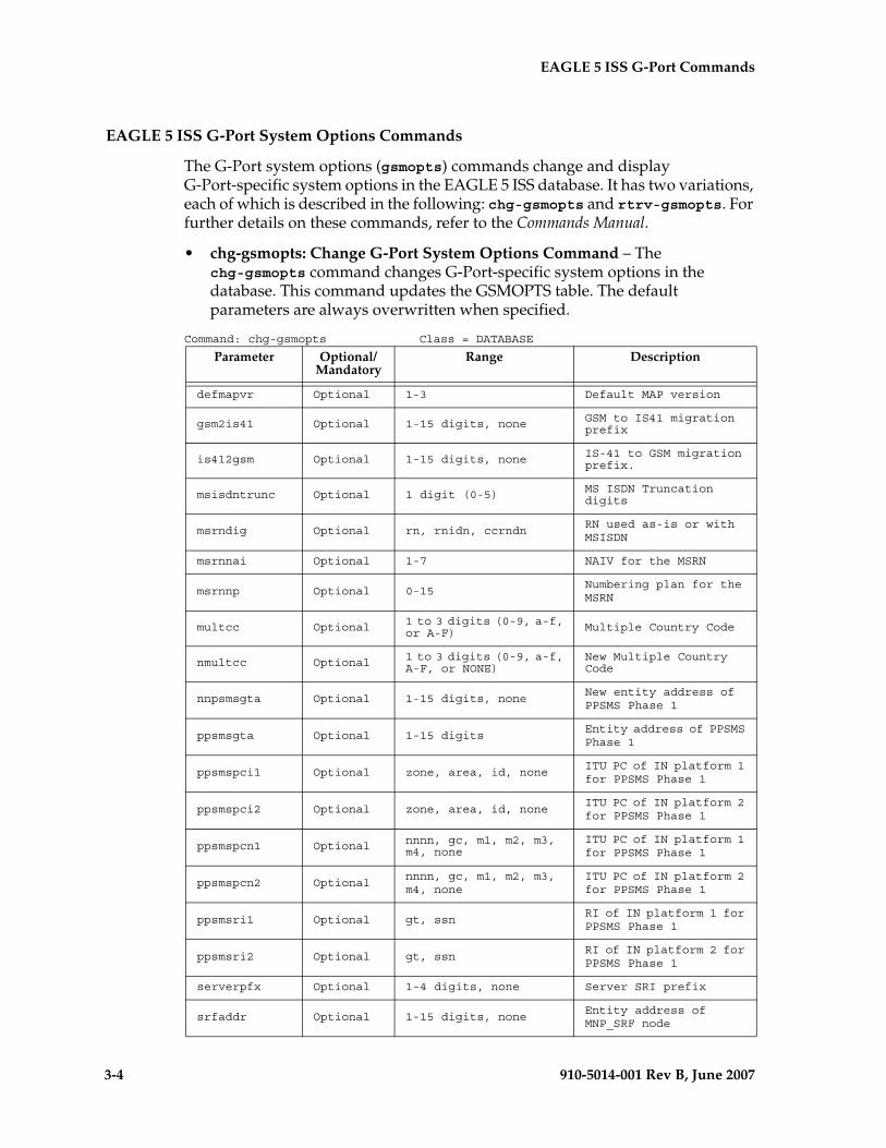
3-4 910-5014-001 Rev B, June 2007
- Prel- Draft -iminary - EAGLE 5 ISS G-Port Commands
EAGLE 5 ISS G-Port System Options Commands
The G-Port system options (gsmopts) commands change and display G-Port-specific system options in the EAGLE 5 ISS database. It has two variations, each of which is described in the following: chg-gsmopts and rtrv-gsmopts. For further details on these commands, refer to the Commands Manual.
• chg-gsmopts: Change G-Port System Options Command – The chg-gsmopts command changes G-Port-specific system options in the database. This command updates the GSMOPTS table. The default parameters are always overwritten when specified.
Command: chg-gsmopts Class = DATABASE
Parameter Optional/ Mandatory
Range Description
defmapvr Optional 1-3 Default MAP version
gsm2is41 Optional 1-15 digits, none GSM to IS41 migration prefix
is412gsm Optional 1-15 digits, none IS-41 to GSM migration prefix.
msisdntrunc Optional 1 digit (0-5) MS ISDN Truncation digits
msrndig Optional rn, rnidn, ccrndnRN used as-is or with MSISDN
msrnnai Optional 1-7 NAIV for the MSRN
msrnnp Optional 0-15Numbering plan for the MSRN
multcc Optional 1 to 3 digits (0-9, a-f, or A-F) Multiple Country Code
nmultcc Optional 1 to 3 digits (0-9, a-f, A-F, or NONE)
New Multiple Country Code
nnpsmsgta Optional 1-15 digits, noneNew entity address of PPSMS Phase 1
ppsmsgta Optional 1-15 digitsEntity address of PPSMS Phase 1
ppsmspci1 Optional zone, area, id, noneITU PC of IN platform 1 for PPSMS Phase 1
ppsmspci2 Optional zone, area, id, noneITU PC of IN platform 2 for PPSMS Phase 1
ppsmspcn1 Optional nnnn, gc, m1, m2, m3, m4, none
ITU PC of IN platform 1 for PPSMS Phase 1
ppsmspcn2 Optionalnnnn, gc, m1, m2, m3, m4, none
ITU PC of IN platform 2 for PPSMS Phase 1
ppsmsri1 Optional gt, ssnRI of IN platform 1 for PPSMS Phase 1
ppsmsri2 Optional gt, ssnRI of IN platform 2 for PPSMS Phase 1
serverpfx Optional 1-4 digits, none Server SRI prefix
srfaddr Optional 1-15 digits, noneEntity address of MNP_SRF node
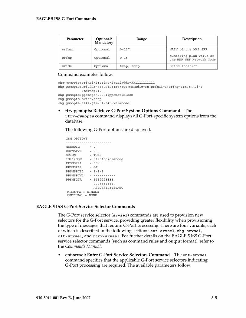
EAGLE 5 ISS G-Port Commands - Prel- Draft -iminary -
910-5014-001 Rev B, June 2007 3-5
Command examples follow.
chg-gsmopts:srfnai=4:srfnp=2:srfaddr=331111111111 chg-gsmopts:srfaddr=333221234567890:msrndig=rn:srfnai=1:srfnp=1:msrnnai=4 :msrnnp=10 chg-gsmopts:ppsmspcn2=234:ppsmsri2=ssnchg-gsmopts:sridn=tcapchg-gsmopts:is412gsm=0123456789abcde
• rtrv-gsmopts: Retrieve G-Port System Options Command – The rtrv-gsmopts command displays all G-Port-specific system options from the database.
The following G-Port options are displayed.
GSM OPTIONS ----------------------- MSRNDIG = 7 DEFMAPVR = 2 SRIDN = TCAP IS412GSM = 0123456789abcde PPSMSRI1 = SSN PPSMSRI2 = GT PPSMSPCI1 = 1-1-1 PPSMSPCN2 = ----------- PPSMSGTA = 1112223333, 2223334444, ABCDEF123456ABC
MIGRPFX = SINGLE GSM2IS41 = NONE
EAGLE 5 ISS G-Port Service Selector Commands
The G-Port service selector (srvsel) commands are used to provision new selectors for the G-Port service, providing greater flexibility when provisioning the type of messages that require G-Port processing. There are four variants, each of which is described in the following sections: ent-srvsel, chg-srvsel, dlt-srvsel, and rtrv-srvsel. For further details on the EAGLE 5 ISS G-Port service selector commands (such as command rules and output format), refer to the Commands Manual.
• ent-srvsel: Enter G-Port Service Selectors Command – The ent-srvsel command specifies that the applicable G-Port service selectors indicating G-Port processing are required. The available parameters follow:
srfnai Optional 0-127 NAIV of the MNP_SRF
srfnp Optional 0-15Numbering plan value of the MNP_SRF Network Code
sridn Optional tcap, sccp SRIDN location
Parameter Optional/ Mandatory
Range Description
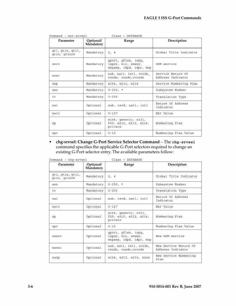
3-6 910-5014-001 Rev B, June 2007
- Prel- Draft -iminary - EAGLE 5 ISS G-Port Commands
Command : ent-srvsel Class = DATABASE
• chg-srvsel: Change G-Port Service Selector Command – The chg-srvsel command specifies the applicable G-Port selectors required to change an existing G-Port selector entry. The available parameters follow:
Command : chg-srvsel Class = DATABASE
Parameter Optional/ Mandatory
Range Description
gti, gtia, gtii, gtin, gtin24
Mandatory 2, 4 Global Title Indicator
serv Mandatorygport, gflex, inpq, inpmr, eir, smsmr, mnpsms, idpd, idpr, mnp
GSM service
snai Mandatorysub, natl, intl, rnidn, rnndn, rnsdn,ccrndn
Service Nature Of Address Indicator
snp Mandatory e164, e212, e214 Service Numbering Plan
ssn Mandatory 0-255, * Subsystem Number
tt Mandatory 0-255 Translation Type
nai Optional sub, rsvd, natl, intlNature Of Address Indicator
naiv Optional 0-127 NAI Value
np Optionale164, generic, x121, f69, e210, e212, e214, private
Numbering Plan
npv Optional 0-15 Numbering Plan Value
Parameter Optional/ Mandatory
Range Description
gti, gtia, gtii, gtin, gtin24
Mandatory 2, 4 Global Title Indicator
ssn Mandatory 0-255, * Subsystem Number
tt Mandatory 0-255 Translation Type
nai Optional sub, rsvd, natl, intlNature Of Address Indicator
naiv Optional 0-127 NAI Value
np Optionale164, generic, x121, f69, e210, e212, e214, private
Numbering Plan
npv Optional 0-15 Numbering Plan Value
nserv Optionalgport, gflex, inpq, inpmr, eir, smsmr, mnpsms, idpd, idpr, mnp
New GSM service
nsnai Optionalsub, natl, intl, rnidn, rnndn, rnsdn,ccrndn
New Service Nature Of Address Indicator
nsnp Optional e164, e212, e214, noneNew Service Numbering Plan
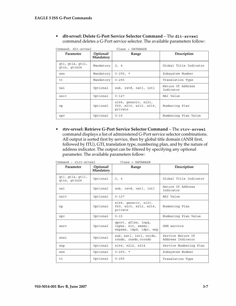
EAGLE 5 ISS G-Port Commands - Prel- Draft -iminary -
910-5014-001 Rev B, June 2007 3-7
• dlt-srvsel: Delete G-Port Service Selector Command – The dlt-srvsel command deletes a G-Port service selector. The available parameters follow:
Command: dlt-srvsel Class = DATABASE
• rtrv-srvsel: Retrieve G-Port Service Selector Command – The rtrv-srvsel command displays a list of administered G-Port service selector combinations. All output is sorted first by service, then by global title domain (ANSI first, followed by ITU), GTI, translation type, numbering plan, and by the nature of address indicator. The output can be filtered by specifying any optional parameter. The available parameters follow:
Command : rtrv-srvsel Class = DATABASE
Parameter Optional/ Mandatory
Range Description
gti, gtia, gtii, gtin, gtin24
Mandatory 2, 4 Global Title Indicator
ssn Mandatory 0-255, * Subsystem Number
tt Mandatory 0-255 Translation Type
nai Optional sub, rsvd, natl, intlNature Of Address Indicator
naiv Optional 0-127 NAI Value
np Optionale164, generic, x121, f69, e210, e212, e214, private
Numbering Plan
npv Optional 0-15 Numbering Plan Value
Parameter Optional/ Mandatory
Range Description
gti, gtia, gtii, gtin, gtin24
Optional 2, 4 Global Title Indicator
nai Optional sub, rsvd, natl, intlNature Of Address Indicator
naiv Optional 0-127 NAI Value
np Optionale164, generic, x121, f69, e210, e212, e214, private
Numbering Plan
npv Optional 0-15 Numbering Plan Value
serv Optionalgport, gflex, inpq, inpmr, eir, smsmr, mnpsms, idpd, idpr, mnp
GSM service
snai Optionalsub, natl, intl, rnidn, rnndn, rnsdn,ccrndn
Service Nature Of Address Indicator
snp Optional e164, e212, e214 Service Numbering Plan
ssn Optional 0-255, * Subsystem Number
tt Optional 0-255 Translation Type
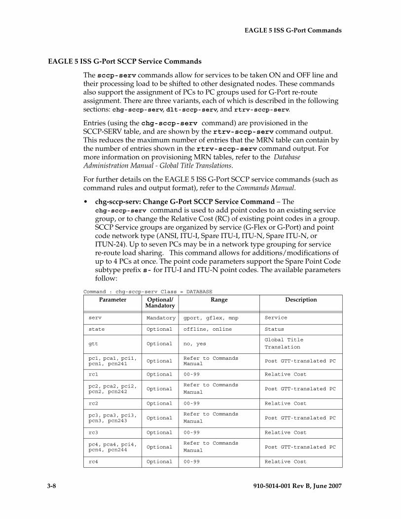
3-8 910-5014-001 Rev B, June 2007
- Prel- Draft -iminary - EAGLE 5 ISS G-Port Commands
EAGLE 5 ISS G-Port SCCP Service Commands
The sccp-serv commands allow for services to be taken ON and OFF line and their processing load to be shifted to other designated nodes. These commands also support the assignment of PCs to PC groups used for G-Port re-route assignment. There are three variants, each of which is described in the following sections: chg-sccp-serv, dlt-sccp-serv, and rtrv-sccp-serv.
Entries (using the chg-sccp-serv command) are provisioned in the SCCP-SERV table, and are shown by the rtrv-sccp-serv command output. This reduces the maximum number of entries that the MRN table can contain by the number of entries shown in the rtrv-sccp-serv command output. For more information on provisioning MRN tables, refer to the Database Administration Manual - Global Title Translations.
For further details on the EAGLE 5 ISS G-Port SCCP service commands (such as command rules and output format), refer to the Commands Manual.
• chg-sccp-serv: Change G-Port SCCP Service Command – The chg-sccp-serv command is used to add point codes to an existing service group, or to change the Relative Cost (RC) of existing point codes in a group. SCCP Service groups are organized by service (G-Flex or G-Port) and point code network type (ANSI, ITU-I, Spare ITU-I, ITU-N, Spare ITU-N, or ITUN-24). Up to seven PCs may be in a network type grouping for service re-route load sharing. This command allows for additions/modifications of up to 4 PCs at once. The point code parameters support the Spare Point Code subtype prefix s- for ITU-I and ITU-N point codes. The available parameters follow:
Command : chg-sccp-serv Class = DATABASE
Parameter Optional/ Mandatory
Range Description
serv Mandatory gport, gflex, mnp Service
state Optional offline, online Status
gtt Optional no, yesGlobal Title
Translation
pc1, pca1, pci1, pcn1, pcn241 Optional Refer to Commands
Manual Post GTT-translated PC
rc1 Optional 00-99 Relative Cost
pc2, pca2, pci2, pcn2, pcn242 Optional
Refer to Commands
ManualPost GTT-translated PC
rc2 Optional 00-99 Relative Cost
pc3, pca3, pci3, pcn3, pcn243 Optional
Refer to Commands
ManualPost GTT-translated PC
rc3 Optional 00-99 Relative Cost
pc4, pca4, pci4, pcn4, pcn244 Optional
Refer to Commands
ManualPost GTT-translated PC
rc4 Optional 00-99 Relative Cost
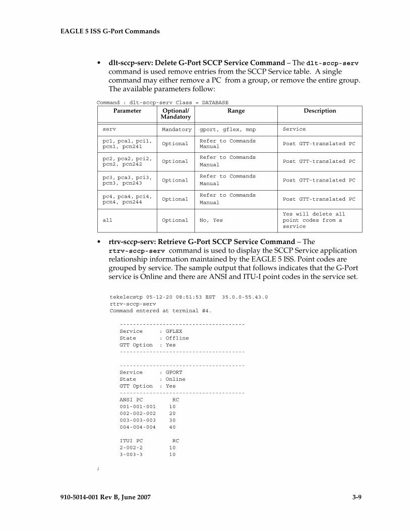
EAGLE 5 ISS G-Port Commands - Prel- Draft -iminary -
910-5014-001 Rev B, June 2007 3-9
• dlt-sccp-serv: Delete G-Port SCCP Service Command – The dlt-sccp-serv command is used remove entries from the SCCP Service table. A single command may either remove a PC from a group, or remove the entire group. The available parameters follow:
Command : dlt-sccp-serv Class = DATABASE
• rtrv-sccp-serv: Retrieve G-Port SCCP Service Command – The rtrv-sccp-serv command is used to display the SCCP Service application relationship information maintained by the EAGLE 5 ISS. Point codes are grouped by service. The sample output that follows indicates that the G-Port service is Online and there are ANSI and ITU-I point codes in the service set.
tekelecstp 05-12-20 08:51:53 EST 35.0.0-55.43.0 rtrv-sccp-serv Command entered at terminal #4.
-------------------------------------- Service : GFLEX State : Offline GTT Option : Yes --------------------------------------
-------------------------------------- Service : GPORT State : Online GTT Option : Yes -------------------------------------- ANSI PC RC 001-001-001 10 002-002-002 20 003-003-003 30 004-004-004 40
ITUI PC RC 2-002-2 10 3-003-3 10
;
Parameter Optional/ Mandatory
Range Description
serv Mandatory gport, gflex, mnp Service
pc1, pca1, pci1, pcn1, pcn241 Optional Refer to Commands
Manual Post GTT-translated PC
pc2, pca2, pci2, pcn2, pcn242 Optional
Refer to Commands
ManualPost GTT-translated PC
pc3, pca3, pci3, pcn3, pcn243 Optional
Refer to Commands
ManualPost GTT-translated PC
pc4, pca4, pci4, pcn4, pcn244 Optional
Refer to Commands
ManualPost GTT-translated PC
all Optional No, YesYes will delete all point codes from a service
3-10 910-5014-001 Rev B, June 2007
- Prel- Draft -iminary - EAGLE 5 ISS G-Port Commands
EAGLE 5 ISS Feature Key Control Commands
These commands are used to enable, update, view, and control the G-Port, MNPCRP, and PPSMS features on the EAGLE 5 ISS. A separate Feature Access Key is required to turn-on each feature. Features must be purchased in order to have access to the Feature Access Key, which must be used when enabling these features.
There are temporary keys associated with the PPSMS nd MNPCRP features. There is no temporary key associated with the G-Port feature and once it is turned-on, it cannot be turned off. There are two steps that will be taken to turn the G-Port feature on. The first step is to enable the feature. The second step is to turn the status to on.
Additional verifications are done to ensure the correct hardware is present in the system. These checks include verifying that the GTT bit is on and that there are no SCCP GLP cards provisioned. Refer to the Commands Manual for details of this command.
Part number 893017201 is used to enable the G-Port feature on the EAGLE 5 ISS.
Part number 893007001 is used to enable the MNPCRP feature on the EAGLE 5 ISS.
Part number 893006701 is used to enable the PPSMS feature on the EAGLE 5 ISS.
• enable-ctrl-feat: Enable Control Feature Command – The enable-ctrl-feat command is used for temporary (PPSMS, MNPCRP) and permanent enabling of the features. An example of the command using the G-Port part number follows:enable-ctrl-feat:partnum=893017201:fak=<Feature Access Key>
• chg-ctrl-feat: Change Control Feature Command – The chg-ctrl-feat command is used to activate or deactivate the G-Port, MNPCRP, and PPSMS features. The G-Port, MNPCRP and PPSMS features require the G-Port feature to be enabled as a prerequisite. This command is also used to clear the temporary key expired critical alarm for the PPSMS and MNPCRP features. An example of the command using the MNPCRP part number follows:chg-ctrl-feat:partnum=893007001:status=on
• rtrv-ctrl-feat: Retrieve Control Feature Command – The rtrv-ctrl-feat command is used display the status of the features (on/off) and to show the trial period remaining if temporarily enabled. An example output follows :
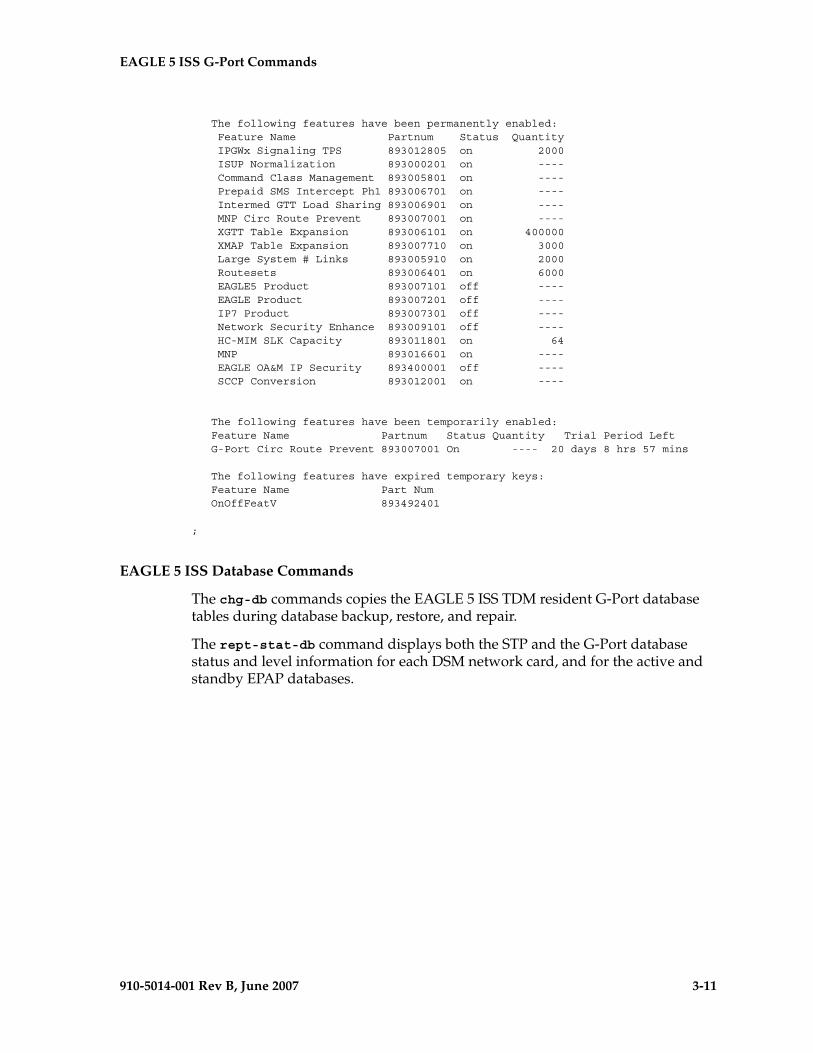
EAGLE 5 ISS G-Port Commands - Prel- Draft -iminary -
910-5014-001 Rev B, June 2007 3-11
The following features have been permanently enabled: Feature Name Partnum Status Quantity IPGWx Signaling TPS 893012805 on 2000 ISUP Normalization 893000201 on ---- Command Class Management 893005801 on ---- Prepaid SMS Intercept Ph1 893006701 on ---- Intermed GTT Load Sharing 893006901 on ---- MNP Circ Route Prevent 893007001 on ---- XGTT Table Expansion 893006101 on 400000 XMAP Table Expansion 893007710 on 3000 Large System # Links 893005910 on 2000 Routesets 893006401 on 6000 EAGLE5 Product 893007101 off ---- EAGLE Product 893007201 off ---- IP7 Product 893007301 off ---- Network Security Enhance 893009101 off ---- HC-MIM SLK Capacity 893011801 on 64 MNP 893016601 on ---- EAGLE OA&M IP Security 893400001 off ---- SCCP Conversion 893012001 on ----
The following features have been temporarily enabled: Feature Name Partnum Status Quantity Trial Period Left G-Port Circ Route Prevent 893007001 On ---- 20 days 8 hrs 57 mins
The following features have expired temporary keys: Feature Name Part Num OnOffFeatV 893492401
;
EAGLE 5 ISS Database Commands
The chg-db commands copies the EAGLE 5 ISS TDM resident G-Port database tables during database backup, restore, and repair.
The rept-stat-db command displays both the STP and the G-Port database status and level information for each DSM network card, and for the active and standby EPAP databases.
3-12 910-5014-001 Rev B, June 2007
- Prel- Draft -iminary - EAGLE 5 ISS G-Port Commands
Maintenance and Measurements User Interface
This section provides a description of the user interface for maintenance and measurements for the G-Port features. The commands that follow allow provisioning, operations, and maintenance activities for DSM cards.
Maintenance Commands
The command examples shown illustrate the requirements and provide suggestions for suitable names and output. The commands are described in detail in the Commands Manual, where the actual parameter names, valid values, and output for the commands are provided.
Commands described here include:
• rept-stat-sys
• rept-stat-sccp
• rept-stat-mps
• rept-meas
• chg-measopts
• rept-stat-meas
• rept-ftp-meas
• rtrv-measopts
• rept-stat-trbl
• rept-stat-alm
• rept-stat-db
• inh-card / alw-card
• chg-sid / dlt-sid
• ent-card / rtrv-card / dlt-card
• chg-gpl / act-gpl / rtrv-gpl / rept-stat-gpl / copy-gpl
• inh-alm / unhb-alm
• pass, including ping, netstat, nslookup, arp, and help commands
rept-stat-sys
The rept-stat-sys command is used to determine the location of troubles in the system. The display shows the number of these items that are in service (IS-NR) and how many are in another state (IS-ANR, OOS-MT, OOS-MT-DSBLD).
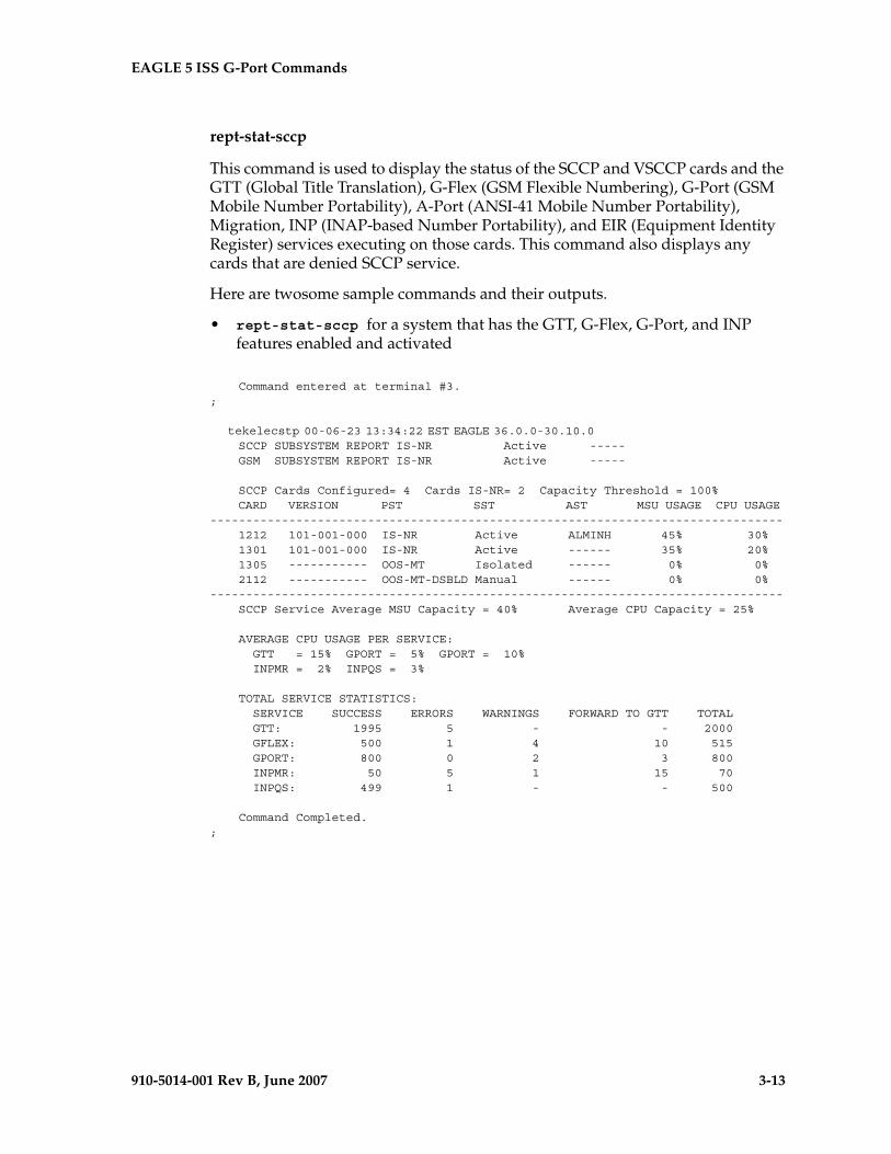
EAGLE 5 ISS G-Port Commands - Prel- Draft -iminary -
910-5014-001 Rev B, June 2007 3-13
rept-stat-sccp
This command is used to display the status of the SCCP and VSCCP cards and the GTT (Global Title Translation), G-Flex (GSM Flexible Numbering), G-Port (GSM Mobile Number Portability), A-Port (ANSI-41 Mobile Number Portability), Migration, INP (INAP-based Number Portability), and EIR (Equipment Identity Register) services executing on those cards. This command also displays any cards that are denied SCCP service.
Here are twosome sample commands and their outputs.
• rept-stat-sccp for a system that has the GTT, G-Flex, G-Port, and INP features enabled and activated
Command entered at terminal #3.;
tekelecstp 00-06-23 13:34:22 EST EAGLE 36.0.0-30.10.0 SCCP SUBSYSTEM REPORT IS-NR Active ----- GSM SUBSYSTEM REPORT IS-NR Active -----
SCCP Cards Configured= 4 Cards IS-NR= 2 Capacity Threshold = 100% CARD VERSION PST SST AST MSU USAGE CPU USAGE -------------------------------------------------------------------------------- 1212 101-001-000 IS-NR Active ALMINH 45% 30% 1301 101-001-000 IS-NR Active ------ 35% 20% 1305 ----------- OOS-MT Isolated ------ 0% 0% 2112 ----------- OOS-MT-DSBLD Manual ------ 0% 0% -------------------------------------------------------------------------------- SCCP Service Average MSU Capacity = 40% Average CPU Capacity = 25%
AVERAGE CPU USAGE PER SERVICE: GTT = 15% GPORT = 5% GPORT = 10% INPMR = 2% INPQS = 3%
TOTAL SERVICE STATISTICS: SERVICE SUCCESS ERRORS WARNINGS FORWARD TO GTT TOTAL GTT: 1995 5 - - 2000 GFLEX: 500 1 4 10 515 GPORT: 800 0 2 3 800 INPMR: 50 5 1 15 70 INPQS: 499 1 - - 500
Command Completed.;
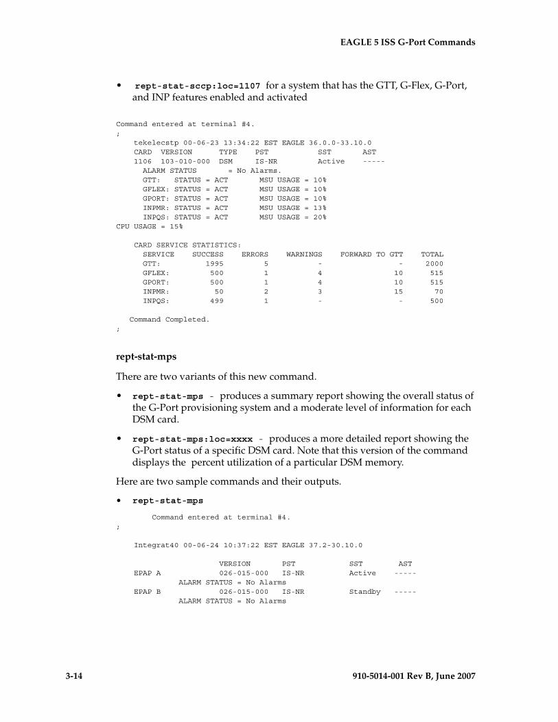
3-14 910-5014-001 Rev B, June 2007
- Prel- Draft -iminary - EAGLE 5 ISS G-Port Commands
• rept-stat-sccp:loc=1107 for a system that has the GTT, G-Flex, G-Port, and INP features enabled and activated
Command entered at terminal #4.; tekelecstp 00-06-23 13:34:22 EST EAGLE 36.0.0-33.10.0 CARD VERSION TYPE PST SST AST 1106 103-010-000 DSM IS-NR Active ----- ALARM STATUS = No Alarms. GTT: STATUS = ACT MSU USAGE = 10% GFLEX: STATUS = ACT MSU USAGE = 10% GPORT: STATUS = ACT MSU USAGE = 10% INPMR: STATUS = ACT MSU USAGE = 13% INPQS: STATUS = ACT MSU USAGE = 20% CPU USAGE = 15% CARD SERVICE STATISTICS: SERVICE SUCCESS ERRORS WARNINGS FORWARD TO GTT TOTAL GTT: 1995 5 - - 2000 GFLEX: 500 1 4 10 515 GPORT: 500 1 4 10 515 INPMR: 50 2 3 15 70 INPQS: 499 1 - - 500
Command Completed.;
rept-stat-mps
There are two variants of this new command.
• rept-stat-mps - produces a summary report showing the overall status of the G-Port provisioning system and a moderate level of information for each DSM card.
• rept-stat-mps:loc=xxxx - produces a more detailed report showing the G-Port status of a specific DSM card. Note that this version of the command displays the percent utilization of a particular DSM memory.
Here are two sample commands and their outputs.
• rept-stat-mps
Command entered at terminal #4.;
Integrat40 00-06-24 10:37:22 EST EAGLE 37.2-30.10.0
VERSION PST SST AST EPAP A 026-015-000 IS-NR Active ----- ALARM STATUS = No Alarms EPAP B 026-015-000 IS-NR Standby ----- ALARM STATUS = No Alarms
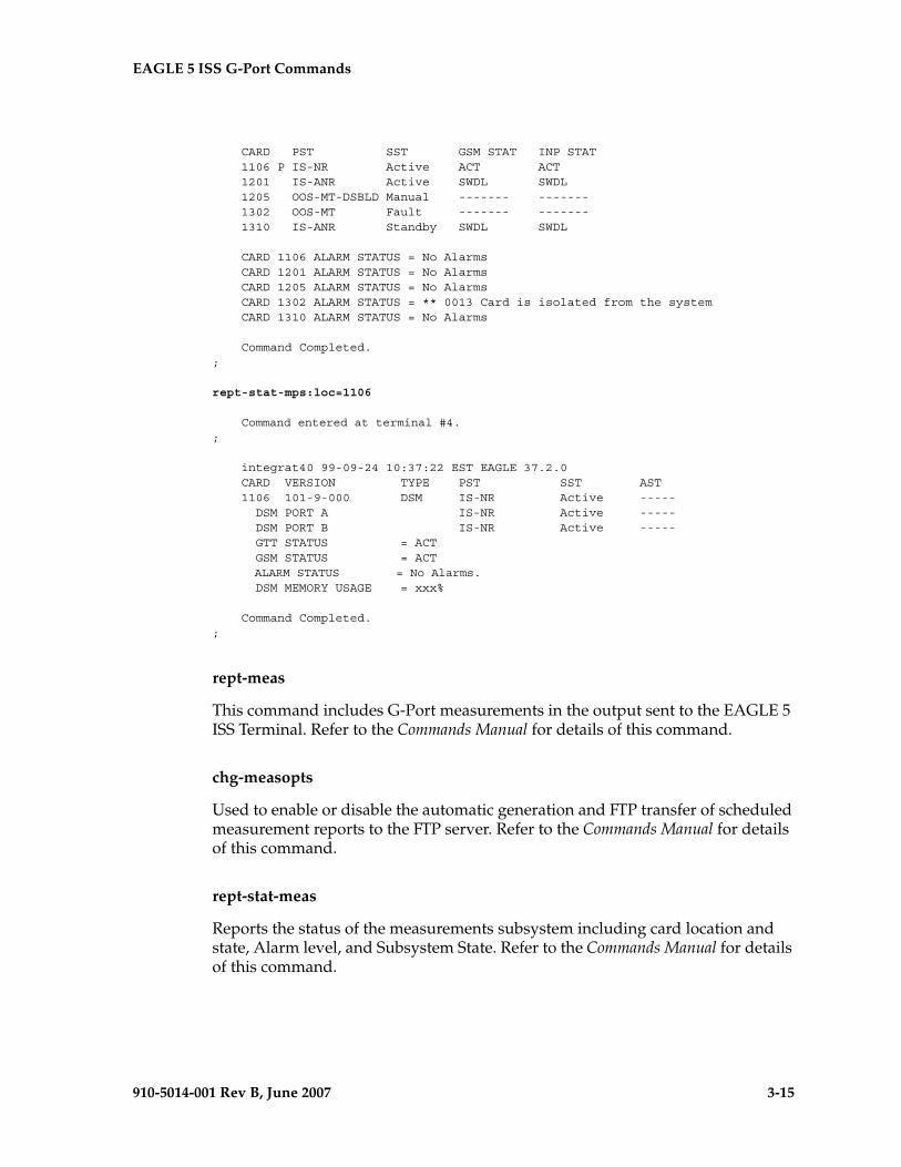
EAGLE 5 ISS G-Port Commands - Prel- Draft -iminary -
910-5014-001 Rev B, June 2007 3-15
CARD PST SST GSM STAT INP STAT 1106 P IS-NR Active ACT ACT 1201 IS-ANR Active SWDL SWDL 1205 OOS-MT-DSBLD Manual ------- ------- 1302 OOS-MT Fault ------- ------- 1310 IS-ANR Standby SWDL SWDL
CARD 1106 ALARM STATUS = No Alarms CARD 1201 ALARM STATUS = No Alarms CARD 1205 ALARM STATUS = No Alarms CARD 1302 ALARM STATUS = ** 0013 Card is isolated from the system CARD 1310 ALARM STATUS = No Alarms
Command Completed.;
rept-stat-mps:loc=1106
Command entered at terminal #4.;
integrat40 99-09-24 10:37:22 EST EAGLE 37.2.0 CARD VERSION TYPE PST SST AST 1106 101-9-000 DSM IS-NR Active ----- DSM PORT A IS-NR Active ----- DSM PORT B IS-NR Active ----- GTT STATUS = ACT GSM STATUS = ACT ALARM STATUS = No Alarms. DSM MEMORY USAGE = xxx%
Command Completed.;
rept-meas
This command includes G-Port measurements in the output sent to the EAGLE 5 ISS Terminal. Refer to the Commands Manual for details of this command.
chg-measopts
Used to enable or disable the automatic generation and FTP transfer of scheduled measurement reports to the FTP server. Refer to the Commands Manual for details of this command.
rept-stat-meas
Reports the status of the measurements subsystem including card location and state, Alarm level, and Subsystem State. Refer to the Commands Manual for details of this command.
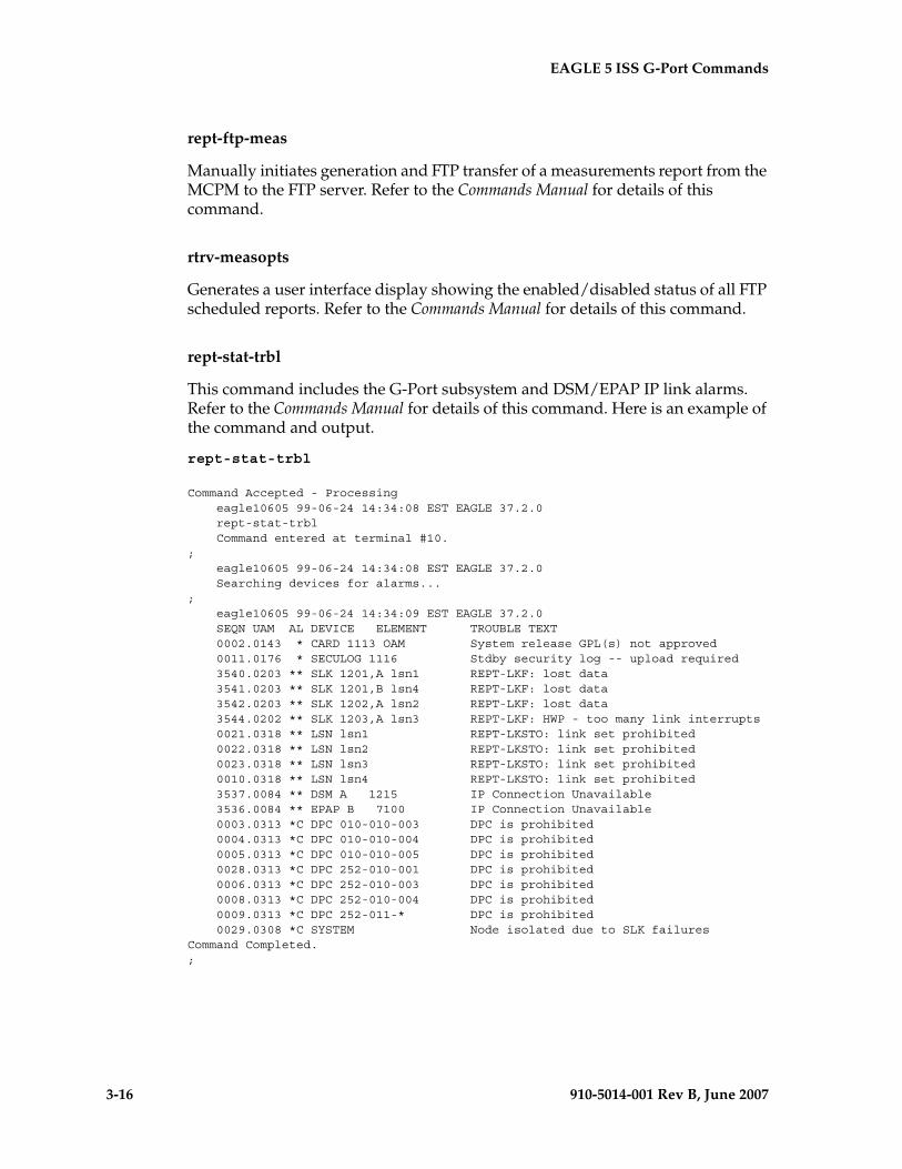
3-16 910-5014-001 Rev B, June 2007
- Prel- Draft -iminary - EAGLE 5 ISS G-Port Commands
rept-ftp-meas
Manually initiates generation and FTP transfer of a measurements report from the MCPM to the FTP server. Refer to the Commands Manual for details of this command.
rtrv-measopts
Generates a user interface display showing the enabled/disabled status of all FTP scheduled reports. Refer to the Commands Manual for details of this command.
rept-stat-trbl
This command includes the G-Port subsystem and DSM/EPAP IP link alarms. Refer to the Commands Manual for details of this command. Here is an example of the command and output.
rept-stat-trbl
Command Accepted - Processing eagle10605 99-06-24 14:34:08 EST EAGLE 37.2.0 rept-stat-trbl Command entered at terminal #10.; eagle10605 99-06-24 14:34:08 EST EAGLE 37.2.0 Searching devices for alarms...; eagle10605 99-06-24 14:34:09 EST EAGLE 37.2.0 SEQN UAM AL DEVICE ELEMENT TROUBLE TEXT 0002.0143 * CARD 1113 OAM System release GPL(s) not approved 0011.0176 * SECULOG 1116 Stdby security log -- upload required 3540.0203 ** SLK 1201,A lsn1 REPT-LKF: lost data 3541.0203 ** SLK 1201,B lsn4 REPT-LKF: lost data 3542.0203 ** SLK 1202,A lsn2 REPT-LKF: lost data 3544.0202 ** SLK 1203,A lsn3 REPT-LKF: HWP - too many link interrupts 0021.0318 ** LSN lsn1 REPT-LKSTO: link set prohibited 0022.0318 ** LSN lsn2 REPT-LKSTO: link set prohibited 0023.0318 ** LSN lsn3 REPT-LKSTO: link set prohibited 0010.0318 ** LSN lsn4 REPT-LKSTO: link set prohibited 3537.0084 ** DSM A 1215 IP Connection Unavailable 3536.0084 ** EPAP B 7100 IP Connection Unavailable 0003.0313 *C DPC 010-010-003 DPC is prohibited 0004.0313 *C DPC 010-010-004 DPC is prohibited 0005.0313 *C DPC 010-010-005 DPC is prohibited 0028.0313 *C DPC 252-010-001 DPC is prohibited 0006.0313 *C DPC 252-010-003 DPC is prohibited 0008.0313 *C DPC 252-010-004 DPC is prohibited 0009.0313 *C DPC 252-011-* DPC is prohibited 0029.0308 *C SYSTEM Node isolated due to SLK failuresCommand Completed.;
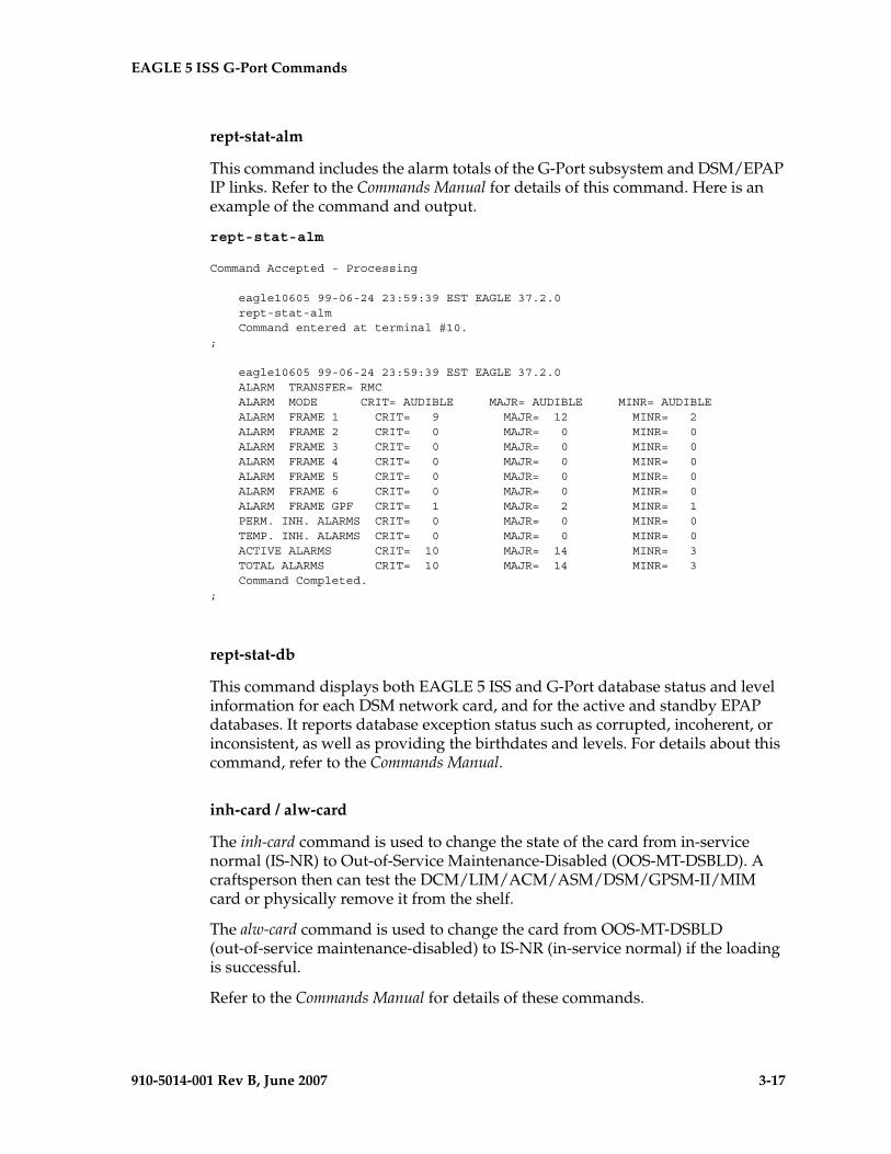
EAGLE 5 ISS G-Port Commands - Prel- Draft -iminary -
910-5014-001 Rev B, June 2007 3-17
rept-stat-alm
This command includes the alarm totals of the G-Port subsystem and DSM/EPAP IP links. Refer to the Commands Manual for details of this command. Here is an example of the command and output.
rept-stat-alm
Command Accepted - Processing
eagle10605 99-06-24 23:59:39 EST EAGLE 37.2.0 rept-stat-alm Command entered at terminal #10.;
eagle10605 99-06-24 23:59:39 EST EAGLE 37.2.0 ALARM TRANSFER= RMC ALARM MODE CRIT= AUDIBLE MAJR= AUDIBLE MINR= AUDIBLE ALARM FRAME 1 CRIT= 9 MAJR= 12 MINR= 2 ALARM FRAME 2 CRIT= 0 MAJR= 0 MINR= 0 ALARM FRAME 3 CRIT= 0 MAJR= 0 MINR= 0 ALARM FRAME 4 CRIT= 0 MAJR= 0 MINR= 0 ALARM FRAME 5 CRIT= 0 MAJR= 0 MINR= 0 ALARM FRAME 6 CRIT= 0 MAJR= 0 MINR= 0 ALARM FRAME GPF CRIT= 1 MAJR= 2 MINR= 1 PERM. INH. ALARMS CRIT= 0 MAJR= 0 MINR= 0 TEMP. INH. ALARMS CRIT= 0 MAJR= 0 MINR= 0 ACTIVE ALARMS CRIT= 10 MAJR= 14 MINR= 3 TOTAL ALARMS CRIT= 10 MAJR= 14 MINR= 3 Command Completed.;
rept-stat-db
This command displays both EAGLE 5 ISS and G-Port database status and level information for each DSM network card, and for the active and standby EPAP databases. It reports database exception status such as corrupted, incoherent, or inconsistent, as well as providing the birthdates and levels. For details about this command, refer to the Commands Manual.
inh-card / alw-card
The inh-card command is used to change the state of the card from in-service normal (IS-NR) to Out-of-Service Maintenance-Disabled (OOS-MT-DSBLD). A craftsperson then can test the DCM/LIM/ACM/ASM/DSM/GPSM-II/MIM card or physically remove it from the shelf.
The alw-card command is used to change the card from OOS-MT-DSBLD (out-of-service maintenance-disabled) to IS-NR (in-service normal) if the loading is successful.
Refer to the Commands Manual for details of these commands.

3-18 910-5014-001 Rev B, June 2007
- Prel- Draft -iminary - EAGLE 5 ISS G-Port Commands
chg-sid / dlt-sid
These commands are used to change and report on the self-identification of the EAGLE 5 ISS. The self-identification identifies the EAGLE 5 ISS to other signaling points in the network. This command includes a CPC type for G-Port.
The CPC parameter is used to support incoming messages routed via Intermediate GTT (rt-gt) to the EAGLE 5 ISS (with DPC = CPC) for G-Port. Refer to the Commands Manual for details of this command.
ent-card / rtrv-card / dlt-card
The ent-card command is used to add a card to the database. The card type and application specifies the function assigned to the card.
The rtrv-card command is used to display the information about a card. This command displays thecard type, the application the card is running, the linkset name, the signaling link code, and the ports.
The dlt-card command is used to remove a card entry from the system database.
Refer to the Commands Manual for details on using these commands.
chg-gpl / act-gpl / rtrv-gpl / rept-stat-gpl / copy-gpl
The chg-gpl command is used to copy a generic program load from the source disk to the destination disk (both active and standby disks). The new GPL becomes the trial version on each of the destination disks. This command also copies the system release table to the fixed disks.
The act-gpl command is used to change the status of the trial GPL from “trial” to “approved.” The status of the previously approved GPL is changed to “trial.”
The rtrv-gpl command is used to show the version numbers of the GPLs stored on each fixed disk (TDM) or removable cartridge (MDAL, if available) and the system release table stored on each fixed disk.
The rept-stat-gpl command is used to display the version of GPLs currently running for an application, plus the approved and trial versions of the GPL that will run if the card is restarted.
The copy-gpl command is used to copy all approved GPLs from one drive to another. The GPLs can be copied only from the fixed disk on the active TDM to the removable cartridge, or from the removable cartridge to the fixed disk on the standby TDM.
Refer to the Commands Manual for details of these commands.
Here are samples of the reports produced by these commands.
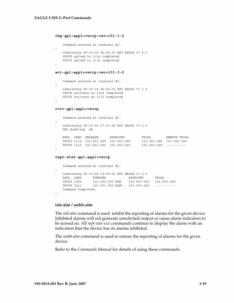
EAGLE 5 ISS G-Port Commands - Prel- Draft -iminary -
910-5014-001 Rev B, June 2007 3-19
chg-gpl:appl=vsccp:ver=101-3-0
Command entered at terminal #3.; tekelecstp 99-10-24 06:54:39 EST EAGLE 37.2.0 VSCCP upload to 1114 completed VSCCP upload to 1116 completed;
act-gpl:appl=vsccp:ver=101-3-0
Command entered at terminal #3.; tekelecstp 99-10-24 06:54:39 EST EAGLE 37.2.0 VSCCP activate on 1114 completed VSCCP activate on 1116 completed;
rtrv-gpl:appl=vsccp
Command entered at terminal #3.; tekelecstp 99-10-04 07:01:08 EST EAGLE 37.2.0 GPL Auditing ON
APPL CARD RELEASE APPROVED TRIAL REMOVE TRIAL VSCCP 1114 101-001-000 101-003-000 101-001-000 101-003-000 VSCCP 1116 101-001-000 101-003-000 101-003-000 -----------;
rept-stat-gpl:appl=vsccp
Command entered at terminal #3.; tekelecstp 99-10-04 12:55:50 EST EAGLE 37.2.0 APPL CARD RUNNING APPROVED TRIAL VSCCP 1205 101-003-000 ALM 101-003-000 101-003-000 VSCCP 1211 101-001-000 ALM+ 101-003-000 ----------- Command Completed.;
inh-alm / unhb-alm
The inh-alm command is used inhibit the reporting of alarms for the given device. Inhibited alarms will not generate unsolicited output or cause alarm indicators to be turned on. All rept-stat-xxx commands continue to display the alarm with an indication that the device has its alarms inhibited.
The unhb-alm command is used to restore the reporting of alarms for the given device.
Refer to the Commands Manual for details of using these commands.

3-20 910-5014-001 Rev B, June 2007
- Prel- Draft -iminary - EAGLE 5 ISS G-Port Commands
chg-ip-card / rtrv-ip-card
The chg-ip-card command is used to provision the Internet Protocol networking parameters for any given DSM card.
The rtrv-ip-card command is used to report on the Internet Protocol networking parameters for any given DSM card.
Refer to the Commands Manual for details of these commands.
chg-ip-lnk / rtrv-ip-lnk
The chg-ip-lnk command is used to provision the Internet Protocol link table.
The rtrv-ip-lnk command is used to report on the Internet Protocol link table.
Refer to the Commands Manual for details of these commands.
ent-ip-host / dlt-ip-host / rtrv-ip-host
These commands are used to provision, remove, and report on the entries in the Internet Protocol host table. The IP host table defines local and remote host names for IP addresses.
Refer to the Commands Manual for details of these commands.
pass
The pass command allows remote execution of a selected command by the targeted card. (These commands recognize the DSM boards.) Selected commands are allowed as follows.
• pass:cmd="ping"
• pass:cmd="netstat"
• pass:cmd="nslookup"
• pass:cmd="arp"
• pass:cmd="help"
For this feature, the loc parameter must be a VSCCP card location. For other details of the pass command, refer to Commands Manual.
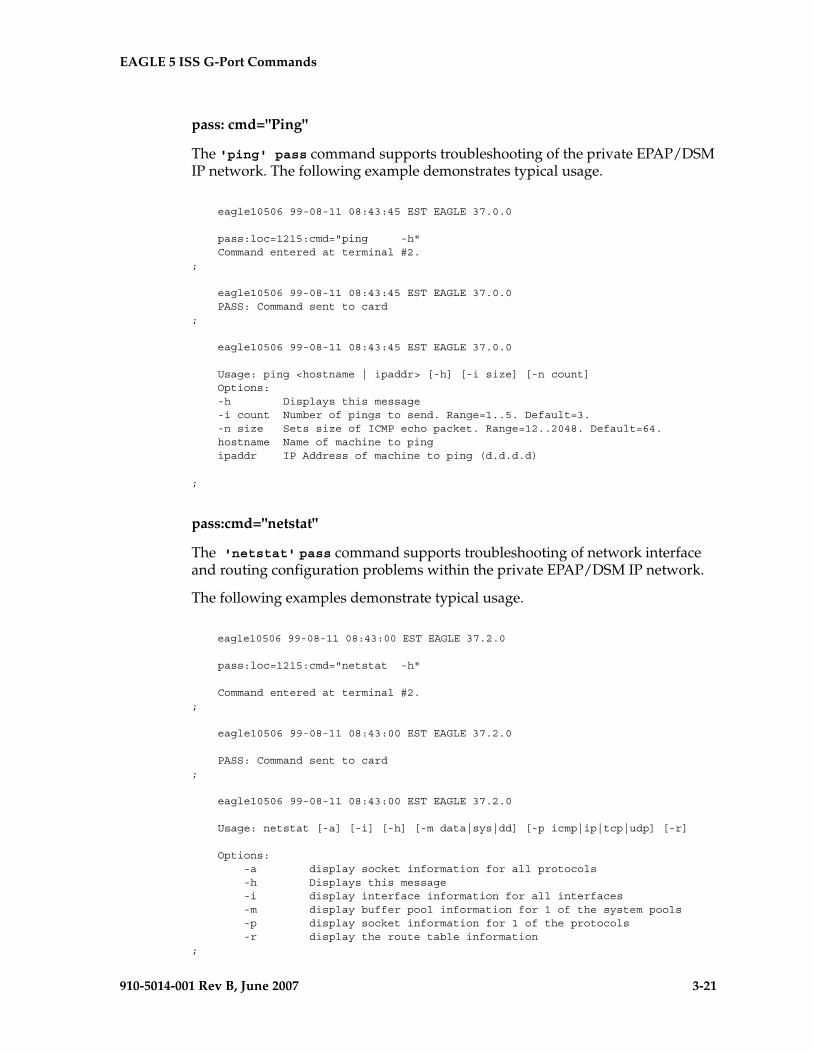
EAGLE 5 ISS G-Port Commands - Prel- Draft -iminary -
910-5014-001 Rev B, June 2007 3-21
pass: cmd="Ping"
The 'ping' pass command supports troubleshooting of the private EPAP/DSM IP network. The following example demonstrates typical usage.
eagle10506 99-08-11 08:43:45 EST EAGLE 37.0.0
pass:loc=1215:cmd="ping -h" Command entered at terminal #2.;
eagle10506 99-08-11 08:43:45 EST EAGLE 37.0.0 PASS: Command sent to card;
eagle10506 99-08-11 08:43:45 EST EAGLE 37.0.0
Usage: ping <hostname | ipaddr> [-h] [-i size] [-n count] Options: -h Displays this message -i count Number of pings to send. Range=1..5. Default=3. -n size Sets size of ICMP echo packet. Range=12..2048. Default=64. hostname Name of machine to ping ipaddr IP Address of machine to ping (d.d.d.d)
;
pass:cmd="netstat"
The 'netstat' pass command supports troubleshooting of network interface and routing configuration problems within the private EPAP/DSM IP network.
The following examples demonstrate typical usage.
eagle10506 99-08-11 08:43:00 EST EAGLE 37.2.0
pass:loc=1215:cmd="netstat -h"
Command entered at terminal #2.;
eagle10506 99-08-11 08:43:00 EST EAGLE 37.2.0
PASS: Command sent to card;
eagle10506 99-08-11 08:43:00 EST EAGLE 37.2.0
Usage: netstat [-a] [-i] [-h] [-m data|sys|dd] [-p icmp|ip|tcp|udp] [-r]
Options: -a display socket information for all protocols -h Displays this message -i display interface information for all interfaces -m display buffer pool information for 1 of the system pools -p display socket information for 1 of the protocols -r display the route table information;
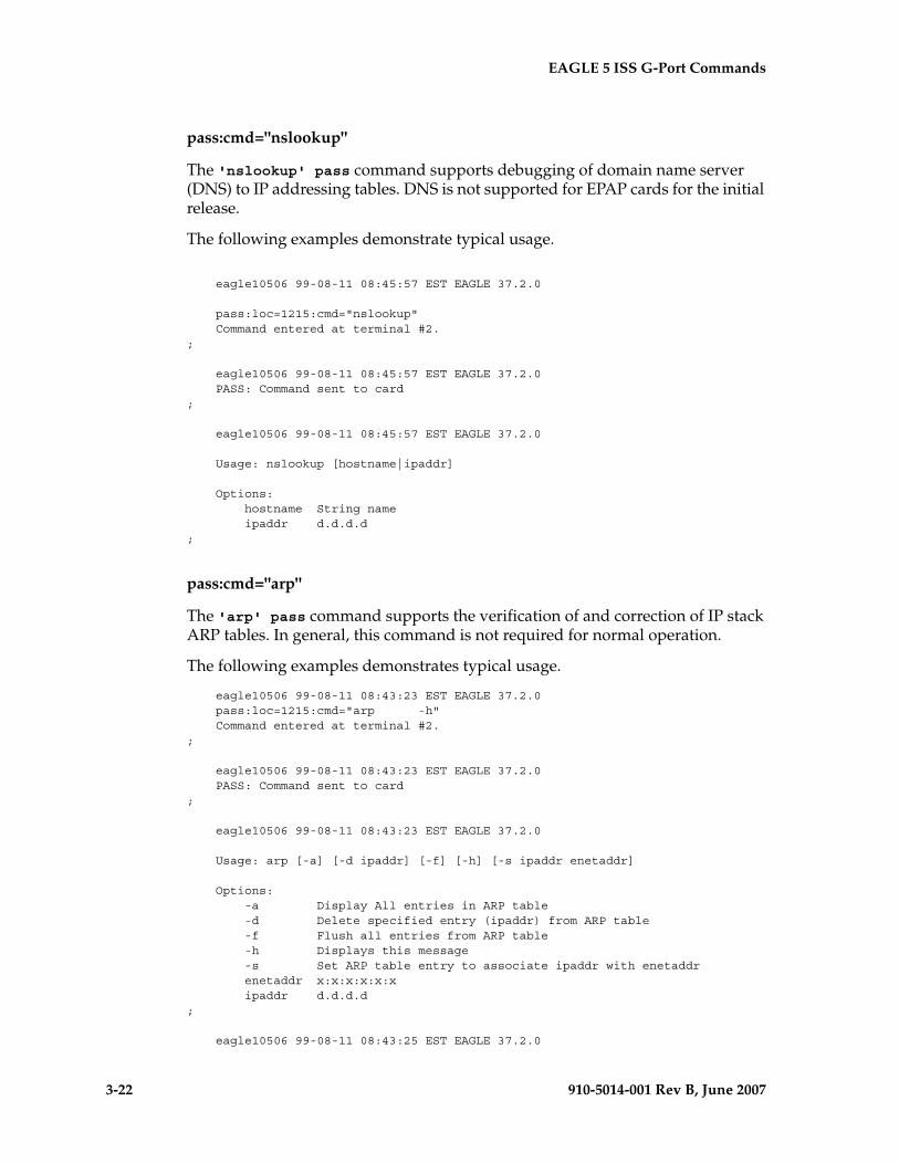
3-22 910-5014-001 Rev B, June 2007
- Prel- Draft -iminary - EAGLE 5 ISS G-Port Commands
pass:cmd="nslookup"
The 'nslookup' pass command supports debugging of domain name server (DNS) to IP addressing tables. DNS is not supported for EPAP cards for the initial release.
The following examples demonstrate typical usage.
eagle10506 99-08-11 08:45:57 EST EAGLE 37.2.0
pass:loc=1215:cmd="nslookup" Command entered at terminal #2.;
eagle10506 99-08-11 08:45:57 EST EAGLE 37.2.0 PASS: Command sent to card;
eagle10506 99-08-11 08:45:57 EST EAGLE 37.2.0
Usage: nslookup [hostname|ipaddr]
Options: hostname String name ipaddr d.d.d.d;
pass:cmd="arp"
The 'arp' pass command supports the verification of and correction of IP stack ARP tables. In general, this command is not required for normal operation.
The following examples demonstrates typical usage.
eagle10506 99-08-11 08:43:23 EST EAGLE 37.2.0 pass:loc=1215:cmd="arp -h" Command entered at terminal #2.;
eagle10506 99-08-11 08:43:23 EST EAGLE 37.2.0 PASS: Command sent to card;
eagle10506 99-08-11 08:43:23 EST EAGLE 37.2.0
Usage: arp [-a] [-d ipaddr] [-f] [-h] [-s ipaddr enetaddr]
Options: -a Display All entries in ARP table -d Delete specified entry (ipaddr) from ARP table -f Flush all entries from ARP table -h Displays this message -s Set ARP table entry to associate ipaddr with enetaddr enetaddr x:x:x:x:x:x ipaddr d.d.d.d;
eagle10506 99-08-11 08:43:25 EST EAGLE 37.2.0
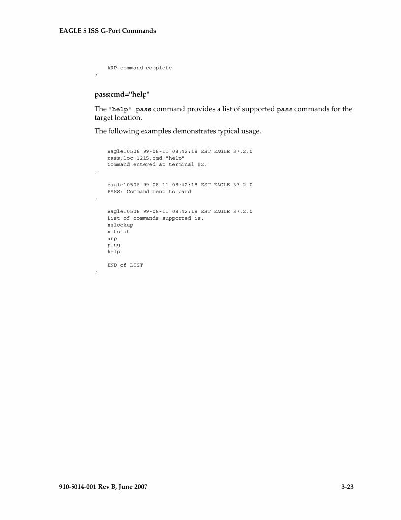
EAGLE 5 ISS G-Port Commands - Prel- Draft -iminary -
910-5014-001 Rev B, June 2007 3-23
ARP command complete;
pass:cmd="help"
The 'help' pass command provides a list of supported pass commands for the target location.
The following examples demonstrates typical usage.
eagle10506 99-08-11 08:42:18 EST EAGLE 37.2.0 pass:loc=1215:cmd="help" Command entered at terminal #2.;
eagle10506 99-08-11 08:42:18 EST EAGLE 37.2.0 PASS: Command sent to card;
eagle10506 99-08-11 08:42:18 EST EAGLE 37.2.0 List of commands supported is: nslookup netstat arp ping help
END of LIST;

3-24 910-5014-001 Rev B, June 2007
- Prel- Draft -iminary - EAGLE 5 ISS G-Port Commands
910-5014-001 Rev B, June 2007 4-1
- Draft -
4
G-Port Feature Activation
Introduction...................................................................................................... 4–1
Prerequisites ..................................................................................................... 4–3
Feature Activation Overview......................................................................... 4–4
Feature Activation Procedure ........................................................................ 4–9
PPSMS Provisioning and Activation .......................................................... 4–40
ISUP NP with EPAP Provisioning and Activation ................................... 4–42
Activating the 1100 TPS/DSM for ITU NP Feature.................................. 4–45
Activating the E5-SM4G Throughput Capacity Feature.......................... 4–52
CAUTION: For an in-service environment, contact the Tekelec Customer Care Center (see “Customer Assistance” on page 1-15) before continuing to activate G-Port. For an environment that is not yet in-service, you may continue with this procedure. The G-Port FAK cannot be enabled if any of the DSMs have less than 1 GB of memory installed. Refer to the Dimensioning Guide for EPAP Advanced DB Features Technical Reference for important information on the dimensioning rules and the DSM database capacity requirements.
Introduction
This chapter identifies prerequisites for the G-Port feature activation procedure, an overview of the activation steps, and a matching number of detailed step descriptions to turn on the G-Port feature. The G-Port feature activation is performed at the EAGLE 5 ISS.
4-2 910-5014-001 Rev B, June 2007
- Draft - G-Port Feature Activation
The G-Port features optimizes the use of subscriber numbers and number ranges in a GSM Mobile Network by providing a logical link between any Mobile Station international ISDN (MSISDN) number and any International Mobile Station Identifier (IMSI). This feature allows subscribers to be moved easily from one Home Location Register (HLR) to another. The G-Port feature applies to ITU-I (international) and ITU-N (national) networks.
The G-Port feature, and other related features, are optional and can be purchased from Tekelec. If you are not sure whether you have purchased a specific feature, contact your Tekelec Sales or Account Representative.
CAUTION: Once a feature has been enabled with the enable-ctrl-feat command, it cannot be turned off. Since features may overwrite other features or create changes in the database, assure that you have a license and full technical support from Tekelec before turning on this or any feature.
The G-Port feature requires a DSM card running the VSCCP application. Systems with TSM cards running the SCCP application need to be upgraded to DSM cards prior to turning on the G-Port feature.
Refer to the Dimensioning Guide for EPAP Advanced DB Features Technical Reference for important information on the dimensioning rules and the DSM database capacity requirements.
Procedures described in the remainder of this section apply only to the G-Port feature and can only be performed if the G-Port feature is turned on.
The following features are related to the G-Port feature (see your Tekelec Sales or Account Representative for additional information):
• Global Title Translation (GTT)
• Enhanced Global Title Translation (EGTT)
• Variable-Length Global Title Translation (VGTT)
• Eagle Provisioning Application Processor (EPAP)
• Mobile Number Portability Circular Route Prevention (MNPCRP)
• Prepaid Short Message Service (PPSMS)
In addition, the following performance-related features are related to G-Port:
• E5-SM4G Throughput Capacity
G-Port Feature Activation - Pr- Draft -elim
910-5014-001 Rev B, June 2007 4-3
Prerequisites
The G-Port feature activation assumes that the features Global Title Translation (GTT), Enhanced Global Title Translation (EGTT), and Variable-Length Global Title Translation (VGTT) are already provisioned. Refer to the Database Administration Manual - Global Title Translation for provisioning procedures.
The G-Port feature activation assumes that the EPAP software is already configured; refer to EPAP Administration Manual, EPAP Software Configuration.
The G-Port feature activation assumes that DSM cards to be installed and TSM cards to be removed are identified:
• Note installed DSM card locations if any
• Note available odd-even card slots for DSM card installation
• Note installed TSM card locations;
• Note adjacent odd-even TSM card slot number positions for DSM card replacement
NOTE: TSM cards use one card slot; DSM cards require two card slots, odd-even.The G-Port feature cannot be turned on until the TSM cards running the SCCP application are removed from the system.
• Determine DSM card IP addresses and have them available during the activation procedure.
For in-service systems, schedule DSM card replacement in maintenance window that allows the reboot of DSM cards (init-card:loc=<DSM card location>) one at a time.
CAUTION: In an in-service environment and when replacing TSM cards with DSM cards, initialize one DSM card at a time. Verify its return to IS-NR state before initializing another DSM card. This precaution keeps cards in service and precludes an interruption of SCCP services.
For in-service systems with TSM cards running SCCP traffic, one DSM card must be installed in an available double-slot odd-even location and provisioned for VSCCP prior to inhibiting the SCCP card. The DSM card running the VSCCP application will take over the SCCP traffic (alw-card) once the SCCP card becomes inhibited.
CAUTION: SCCP traffic redundancy will be lost if inhibiting two SCCP cards at a time with only one VSCCP card available in their place. Redundancy will be re-established once the two SCCP cards are replaced with a second VSCCP card.
4-4 910-5014-001 Rev B, June 2007
- Draft - G-Port Feature Activation
For in-service systems that already have the G-Flex and/or INP feature enabled, only perform steps 70 through 86 to turn on the G-Port feature. With the G-Flex and/or INP feature enabled, the DSM cards already contain the RTDB database.
For new systems, DSM cards may be rebooted all at one time using the init-card:appl=vsccp command.
For new systems, GTT, EGTT, and VGTT features may be turned on prior to or immediately following the reboot of all DSM cards.
Feature Activation Overview
This section provides an overview of the G-Port feature activation procedure. The procedure is described in detail in section “Feature Activation Procedure” on page 4-9.
The feature activation consists of these sections:
• Configure system for HLR destinations in steps 1 through 28.
• Install DSM cards in available slots and configure for VSCCP in steps 29 through 44.
• Replace TSM cards configured for SCCP with DSM cards configured for VSCCP and inhibit/remove any remaining SCCP cards in steps 45 through 69.
• Turn on and configure the G-Port feature in steps 70 through 86.
Steps 1 through 28 configure the system to be able to communicate with the system of the HLR database. The route to this database may already be configured. Perform these steps to verify that you have entered all HLR destinations for G-Port and make configuration changes as needed.
1. Display and note current system settings for point codes (PCs) and capability point codes (CPCs), destination point codes (DPCs), routes, and linksets using steps 1 through 7.
2. Use rtrv-sid command to display current PCs and CPCs.
3. Use rtrv-dstn command to display current DPCs.
4. Use rtrv-rte command to display current route configurations.
5. Identify PCs and CPCs; determine new PC and CPC to be entered in step 9.
6. Use rtrv-stpopts command to display PC or CPC format if ITU-N network.
7. Use rtrv-map command to display PCs of mated applications in database; remove system PC from table if necessary (refer to Database Administration Manual - Global Title Translation.
G-Port Feature Activation - Pr- Draft -elim
910-5014-001 Rev B, June 2007 4-5
CAUTION: Changing a system’s point code requires a system reboot using the init-sys command to fully implement the changes. The init-sys command causes a complete system reload and should be used only in an environment that is not in service. Using this command ensures the updated self identification information is loaded onto all cards, but does interrupt service.
8. Change PC, CPC, DPC, route, linkset, and LIM card configurations for the HLR database using steps 9 through 28.
9. Use chg-sid command to configure PC and CPC by network type.
10. Use init-sys command to initialize system if changes were made in step 9 to any pca/pci/pcn parameter.
CAUTION: The init-sys command causes a complete system reload and should be used only in an environment that is not in service. Using this command ensures the updated self identification information is loaded onto all cards, but does interrupt service.
When the init-sys command executes, the system does not retain the manually initiated state (for example, OOS-MT-DSBLD) for the signaling link, card, or terminal. After the command executes, the system attempts to bring all provisioned links, cards, and terminals on line, including those that were previously out of service. You will need to manually put each device back into its previous state after the system is back on line. Print or electronically capture the output of the rept-stat-slk, rept-stat-card, and rept-stat-trm commands for reference prior to issuing the init-sys command. To restore a device to its previous state, issue the appropriate inhibit/deactivate command listed in the EAGLE 5 ISS Commands Manual in the Related Commands section for each of the above rept-stat commands.
11. Use rtrv-sid command to display new PC and CPC.
12. Use ent-dstn command to enter DPC for HLR destinations.
13. Use rtrv-dstn command to display new HLR DPC.
14. Use ent-ls command to enter linkset and assign DPC for HLR destinations.
15. Use rtrv-ls command to display new linkset and assigned DPC for HLR destinations.
16. Use ent-card command to enter LIM card(s) into database.
17. Use rtrv-card command to display new LIM card(s) in database.
18. Use ent-slk command to assign signaling link(s) to LIM card(s).
19. Use rtrv-slk command to display new signaling link(s) assigned to LIM card(s).
20. Use ent-rte command to assign route to new DPC.

4-6 910-5014-001 Rev B, June 2007
- Draft - G-Port Feature Activation
21. Use rtrv-rte command to display route assigned to new DPC.
22. Use ent-map command to enter mated application into database.
23. Use rtrv-map command to display new mated application in database.
24. Use alw-card command to allow LIM card(s).
25. Use rept-stat-card command to display status of new LIM card(s) in database.
26. Use act-slk command to activate new signaling link(s) for LIM card(s).
27. Use rept-stat-slk command to display IS-NR status of signaling link(s).
28. Use rtrv-card command to confirm the new LIM card(s) and identify VSCCP cards (DSM cards running VSCCP application) and SCCP cards (TSM cards running SCCP application).
CAUTION: When adding DSM cards in an in-service environment, you must take care not to interrupt traffic. Before replacing SCCP cards with DSMs, first install a VSCCP card in an available odd-even double-slot prior to removing SCCP cards to make additional room for other DSM cards.
29. Install and configure DSM card(s) in available odd-even slots as needed using steps 30 through 44.
30. Install DSM card(s) in available odd-even slots and verify green IMT bus LEDs.
31. Use ent-card command to enter DSM card(s) as VSCCP card(s) into database.
32. Use rtrv-card command to display new VSCCP card(s) in database.
33. Use rtrv-ip-lnk command to display current link parameters associated with the VSCCP card.
34. Use chg-ip-lnk command to set the IP address port and speed associated with the VSCCP card.
35. Use rtrv-ip-lnk command to display changed link parameters.Use rtrv-ip-host command to display current IP host information in database.
36. Use ent-ip-host command to add host name and IP address for each VSCCP link.
37. Use rtrv-ip-host command to display changed IP host information.
38. Use chg-ip-card command to set local domain and IP router address if necessary.
39. Use rtrv-ip-card command to display changed VSCCP card information.
40. Use alw-card command to boot DSM card in TSM emulation mode.

G-Port Feature Activation - Pr- Draft -elim
910-5014-001 Rev B, June 2007 4-7
41. Use rept-stat-card command to display IS-NR status of VSCCP card.
42. Use pass command to test presence of EPAP hosts on network.
43. Repeat steps 30 through 43 to add all DSM cards (N+1) to be installed in available slots. Go to the next step to start replacing TSM cards.
44. Replace TSM card(s) with DSM cards if applicable, and add DSM card(s) to database using steps 46 through 68.
45. Use rtrv-card command to display TSM cards running the SCCP application (SCCP cards) in database.
46. Use rept-stat-card command to display SCCP cards in IS-NR status.
47. Use inh-card command to inhibit SCCP card(s)
48. Use rept-stat-card command to display OOS-MT-DSBLD status of SCCP card(s).
49. Use dlt-card command to delete SCCP card(s) from database.
50. Use rtrv-card command to verify removal of SCCP cards from database.
51. Remove first TSM card from shelf.
52. Remove second TSM card from shelf.
53. Install DSM card in shelf and verify green IMT bus LEDs.
54. Use ent-card command to enter DSM card as VSCCP card into database.
55. Use rtrv-card command to display new VSCCP card in database.
56. Use rtrv-ip-lnk command to display current link parameters associated with VSCCP card.
57. Use chg-ip-lnk command to set the IP address port and speed associated with VSCCP card.
58. Use rtrv-ip-lnk command to display changed link parameters associated with the VSCCP card.
59. Use rtrv-ip-host command to display IP host information in database.
60. Use ent-ip-host command to add host name and IP address for VSCCP link.
61. Use rtrv-ip-host command to display changed IP host information in database.
62. Use chg-ip-card command to set local domain and IP router address if necessary.
63. Use rtrv-ip-card command to display changed VSCCP card information.
64. Use alw-card command to boot DSM card in TSM emulation mode.
65. Use rept-stat-card command to display IS-NR status of VSCCP card.

4-8 910-5014-001 Rev B, June 2007
- Draft - G-Port Feature Activation
66. Use pass command to test presence of EPAP hosts on network.
67. Repeat steps 46 through 67 to replace all adjacent TSM cards identified in the prerequisites and to be replaced with DSM cards.
68. Repeat steps 48 through 52 to inhibit any remaining TSM cards running the SCCP application and remove them from database and shelf.
NOTE: The G-Port feature cannot be turned on until TSM cards running the SCCP application are removed from the system.
CAUTION: Contact the Tekelec Customer Care Center at this point for assistance in completing this G-Port activation procedure (see “Customer Assistance” on page 1-15). Do not proceed without consulting with the Tekelec Customer Care Center.
69. Turn on G-Port feature and configure it using steps 70 through 86.
70. Use enable-ctrl-feat command to enable the G-Port feature.
71. Use chg-ctrl-feat command to turn on the G-Port feature.
NOTE: Steps 74 through 81 describe the commands that administer the G-Port protocol flow to support:
• G-Port SRI ACK (Ported-out MSISDNs)
• G-Port SRI ACK (Foreign MSISDNs not known to be ported)
• G-Port Message Relay (Ported-in, non-ported MSISDNs)
72. Use chg-stpopts command to enter default country code (CC) and default network destination code (NDC) if handling non-international numbers.
73. Use rtrv-stpopts command to verify changes of CC and NDC.
74. Use chg-gsmopts command to change GSM options.
75. Use rtrv-gsmopts command to verify changes to GSM options.
76. Use the ent-homern command to enter any Home RNs that are prefixed to DNs for incoming INP MR messages.
77. Use rtrv-homern command to verify routing number prefixes.
78. Use ent-srvsel command to enter G-Port service selectors.
79. Use rtrv-srvsel command to verify changes to G-Port service selectors.
CAUTION: When you have an in-service environment and you are replacing TSM cards with DSM cards, initialize one DSM card at a time. Verify its return to IS-NR state before initializing another card. This precaution keeps cards in service and precludes an interruption of SCCP services.
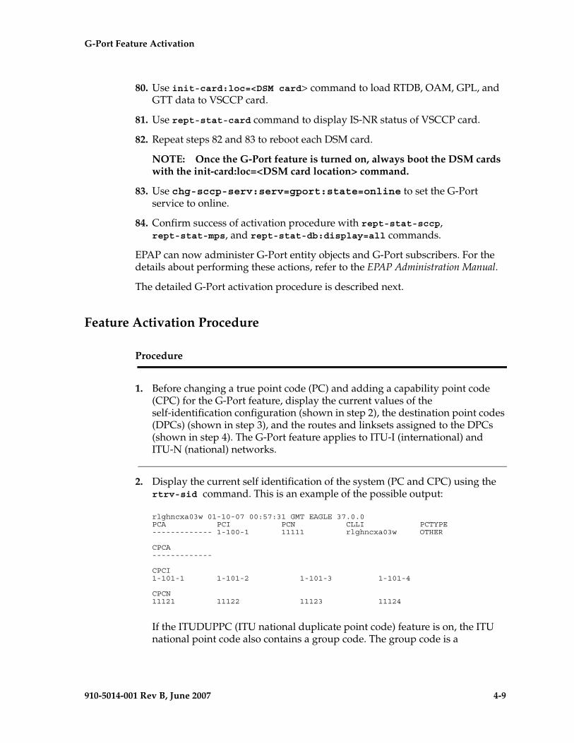
G-Port Feature Activation - Pr- Draft -elim
910-5014-001 Rev B, June 2007 4-9
80. Use init-card:loc=<DSM card> command to load RTDB, OAM, GPL, and GTT data to VSCCP card.
81. Use rept-stat-card command to display IS-NR status of VSCCP card.
82. Repeat steps 82 and 83 to reboot each DSM card.
NOTE: Once the G-Port feature is turned on, always boot the DSM cards with the init-card:loc=<DSM card location> command.
83. Use chg-sccp-serv:serv=gport:state=online to set the G-Port service to online.
84. Confirm success of activation procedure with rept-stat-sccp, rept-stat-mps, and rept-stat-db:display=all commands.
EPAP can now administer G-Port entity objects and G-Port subscribers. For the details about performing these actions, refer to the EPAP Administration Manual.
The detailed G-Port activation procedure is described next.
Feature Activation Procedure
Procedure
1. Before changing a true point code (PC) and adding a capability point code (CPC) for the G-Port feature, display the current values of the self-identification configuration (shown in step 2), the destination point codes (DPCs) (shown in step 3), and the routes and linksets assigned to the DPCs (shown in step 4). The G-Port feature applies to ITU-I (international) and ITU-N (national) networks.
2. Display the current self identification of the system (PC and CPC) using the rtrv-sid command. This is an example of the possible output:
rlghncxa03w 01-10-07 00:57:31 GMT EAGLE 37.0.0PCA PCI PCN CLLI PCTYPE------------- 1-100-1 11111 rlghncxa03w OTHER
CPCA-------------
CPCI1-101-1 1-101-2 1-101-3 1-101-4
CPCN11121 11122 11123 11124
If the ITUDUPPC (ITU national duplicate point code) feature is on, the ITU national point code also contains a group code. The group code is a
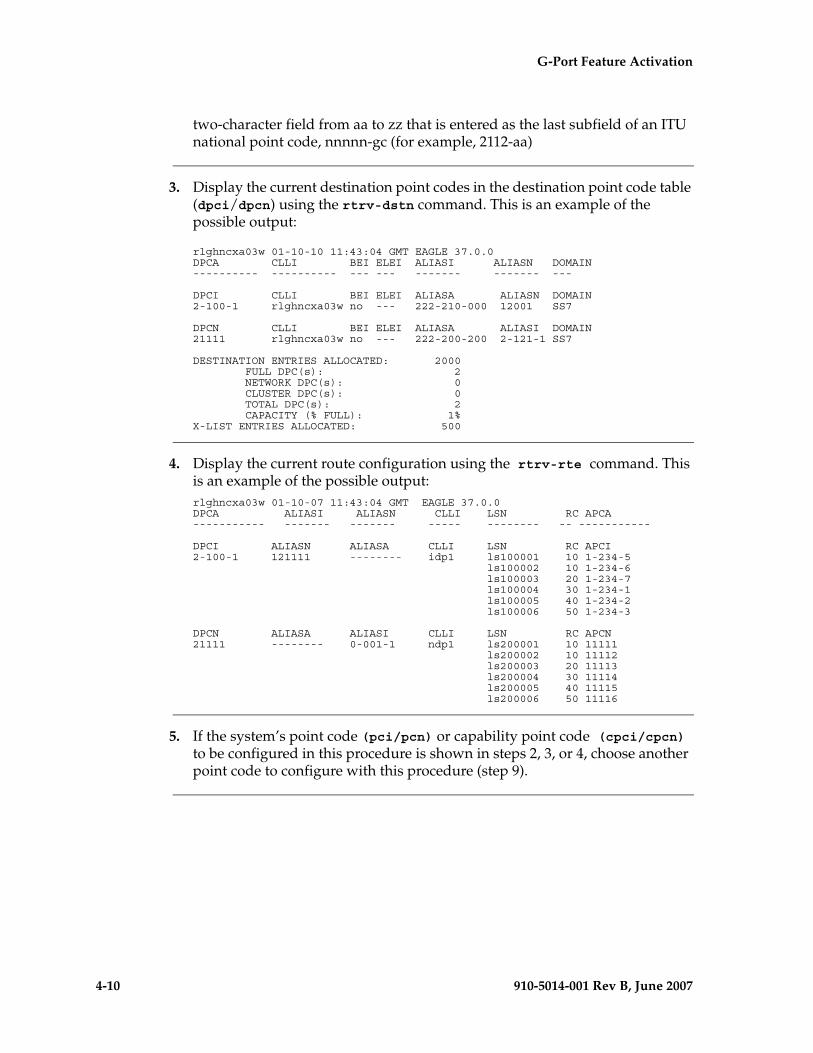
4-10 910-5014-001 Rev B, June 2007
- Draft - G-Port Feature Activation
two-character field from aa to zz that is entered as the last subfield of an ITU national point code, nnnnn-gc (for example, 2112-aa)
3. Display the current destination point codes in the destination point code table (dpci/dpcn) using the rtrv-dstn command. This is an example of the possible output:
rlghncxa03w 01-10-10 11:43:04 GMT EAGLE 37.0.0DPCA CLLI BEI ELEI ALIASI ALIASN DOMAIN---------- ---------- --- --- ------- ------- ---
DPCI CLLI BEI ELEI ALIASA ALIASN DOMAIN2-100-1 rlghncxa03w no --- 222-210-000 12001 SS7
DPCN CLLI BEI ELEI ALIASA ALIASI DOMAIN21111 rlghncxa03w no --- 222-200-200 2-121-1 SS7
DESTINATION ENTRIES ALLOCATED: 2000 FULL DPC(s): 2 NETWORK DPC(s): 0 CLUSTER DPC(s): 0 TOTAL DPC(s): 2 CAPACITY (% FULL): 1%X-LIST ENTRIES ALLOCATED: 500
4. Display the current route configuration using the rtrv-rte command. This is an example of the possible output:rlghncxa03w 01-10-07 11:43:04 GMT EAGLE 37.0.0DPCA ALIASI ALIASN CLLI LSN RC APCA----------- ------- ------- ----- -------- -- -----------
DPCI ALIASN ALIASA CLLI LSN RC APCI2-100-1 121111 -------- idp1 ls100001 10 1-234-5 ls100002 10 1-234-6 ls100003 20 1-234-7 ls100004 30 1-234-1 ls100005 40 1-234-2 ls100006 50 1-234-3
DPCN ALIASA ALIASI CLLI LSN RC APCN21111 -------- 0-001-1 ndp1 ls200001 10 11111 ls200002 10 11112 ls200003 20 11113 ls200004 30 11114 ls200005 40 11115 ls200006 50 11116
5. If the system’s point code (pci/pcn) or capability point code (cpci/cpcn) to be configured in this procedure is shown in steps 2, 3, or 4, choose another point code to configure with this procedure (step 9).
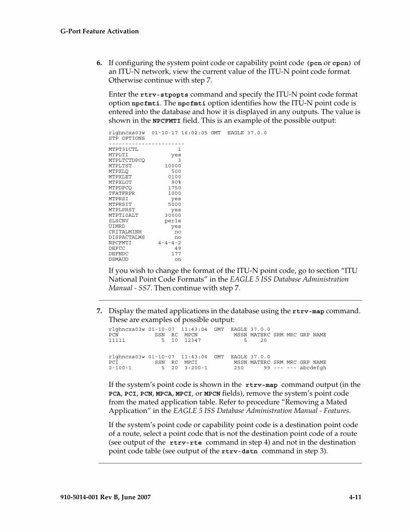
G-Port Feature Activation - Pr- Draft -elim
910-5014-001 Rev B, June 2007 4-11
6. If configuring the system point code or capability point code (pcn or cpcn) of an ITU-N network, view the current value of the ITU-N point code format. Otherwise continue with step 7.
Enter the rtrv-stpopts command and specify the ITU-N point code format option npcfmti. The npcfmti option identifies how the ITU-N point code is entered into the database and how it is displayed in any outputs. The value is shown in the NPCFMTI field. This is an example of the possible output:
rlghncxa03w 01-10-17 16:02:05 GMT EAGLE 37.0.0STP OPTIONS-----------------------MTPT31CTL 1MTPLTI yesMTPLTCTDPCQ 3MTPLTST 10000MTPXLQ 500MTPXLET 0100MTPXLOT 90%MTPDPCQ 1750TFATFRPR 1000MTPRSI yesMTPRSIT 5000MTPLPRST yesMTPT10ALT 30000SLSCNV perlsUIMRD yesCRITALMINH noDISPACTALMS noNPCFMTI 4-4-4-2DEFCC 49DEFNDC 177DSMAUD on
If you wish to change the format of the ITU-N point code, go to section “ITU National Point Code Formats” in the EAGLE 5 ISS Database Administration Manual - SS7. Then continue with step 7.
7. Display the mated applications in the database using the rtrv-map command. These are examples of possible output:rlghncxa03w 01-10-07 11:43:04 GMT EAGLE 37.0.0PCN SSN RC MPCN MSSN MATERC SRM MRC GRP NAME11111 5 10 12347 5 20
rlghncxa03w 01-10-07 11:43:04 GMT EAGLE 37.0.0PCI SSN RC MPCI MSSN MATERC SRM MRC GRP NAME2-100-1 5 20 3-200-1 250 99 --- --- abcdefgh
If the system’s point code is shown in the rtrv-map command output (in the PCA, PCI, PCN, MPCA, MPCI, or MPCN fields), remove the system’s point code from the mated application table. Refer to procedure “Removing a Mated Application” in the EAGLE 5 ISS Database Administration Manual - Features.
If the system’s point code or capability point code is a destination point code of a route, select a point code that is not the destination point code of a route (see output of the rtrv-rte command in step 4) and not in the destination point code table (see output of the rtrv-dstn command in step 3).
4-12 910-5014-001 Rev B, June 2007
- Draft - G-Port Feature Activation
8. Change PC, CPC, DPC, route, linkset, and LIM card configurations for the HLR database using steps 9 through 28.
CAUTION: Changing a system’s point code requires a system reboot using the init-sys command to fully implement the changes. The init-sys command causes a complete system reload and should be used only in an environment that is not in service. Using this command ensures the updated self identification information is loaded onto all cards but does interrupt service.
9. Configure the system’s point code (pci/pcn) and capability point code (cpci/cpcn) by network type using the chg-sid command. For example, enter one of these commands:
chg-sid:pci=1-100-2:cpci=1-102-1
chg-sid:pcn=11112:cpcn=11125
where:
:pci/pcn – The point code used to uniquely identify the system.
:cpci/cpcn – The point code used by the SS7 protocol to identify a group of functionally related EAGLE 5 ISSs in the signaling network to which the EAGLE 5 ISS belongs.
After successful completion of this command, the system returns the following output:
rlghncxa03w 01-10-07 00:57:31 GMT EAGLE 37.0.0CHG-SID: MASP A - COMPLTD
When any of the pci/pcn parameters have changed, the system needs to be reinitialized. The following caution message is displayed:
CAUTION: SYSTEM SITE ID HAS BEEN CHANGED, MANUAL RE-INITIALIZATION IS NEEDED
CAUTION: The init-sys command causes a complete system reload and should be used only in an environment that is not in service. Using this command ensures the updated self identification information is loaded onto all cards, but does interrupt service.
When the init-sys command executes, the system does not retain the manually initiated state (for example, OOS-MT-DSBLD) for the signaling link, card, or terminal. After the command executes, the system attempts to bring all provisioned links, cards, and terminals on line, including those
G-Port Feature Activation - Pr- Draft -elim
910-5014-001 Rev B, June 2007 4-13
that were previously out of service. You will need to manually put each device back into its previous state after the system is back on line. Print or electronically capture the output of the rept-stat-slk, rept-stat-card, and rept-stat-trm commands for reference prior to issuing the init-sys command. To restore a device to its previous state, issue the appropriate inhibit/deactivate command listed in the EAGLE 5 ISS Commands Manual in the Related Commands section for each of the above rept-stat commands.
10. Reinitialize the system by entering the init-sys command if changes were made in step 9 to any pca/pci/pcn parameter.
NOTE: The init-sys command must be entered twice within 30 seconds for the system to re-initialize. If the init-sys command is not executed twice within 30 seconds, the attempt to re-initialize the system is aborted.
When the init-sys command is first entered, this message should appear.
rlghncxa03w 01-10-07 00:57:31 GMT EAGLE 37.0.0CAUTION: This command causes a complete system reload, andwill result in traffic loss.Re-enter command within 30 seconds to confirm.
When the init-sys command is re-entered within the 30 second time limit, this message should appear.rlghncxa03w 01-10-07 00:57:31 GMT EAGLE 37.0.0Init System command issued at terminal #3
From the time that the init-sys command is accepted, you must wait approximately two minutes before you can perform step 11 (logging into the system). If the terminal is in the VT-100/VT-320 mode, the terminal display will be refreshed with non-zero alarm counts. During this two-minute interval, an intermediate screen refresh occurs, which is caused by the MASP’s role change from active to standby and from standby to active. This screen refresh is typically a partial refresh and the alarm indicators are set to zero.
If you are logged into the system in the KSR mode, the only response you will receive of being able to log into the system is the message ‘UAM 0009, MASP became active’. UAM 0009 could be issued twice due to a possible transient MASP role change (switching from active to standby). Following the execution of the init-sys command, the MASP that was active before the init-sys command was entered will be the active MASP again when the system has finished reinitializing.
4-14 910-5014-001 Rev B, June 2007
- Draft - G-Port Feature Activation
11. Verify the SID changes using the rtrv-sid command. This is an example of the possible output:
durhncxa03w 01-10-07 00:57:31 GMT EAGLE 37.0.0PCA PCI PCN CLLI PCTYPE------------- 1-100-1 11111 rlghncxa03w OTHER
CPCA-------------
CPCI1-101-1 1-101-2 1-101-3 1-101-41-102-1
CPCN11121 11122 11123 1112411125
12. Enter a destination point code for the HLR location in the Destination Point Code table by network type using the ent-dstn command. For example, enter one of these commands:
ent-dstn:dpci=2-100-2
ent-dstn:dpcn=21112
where:
:dpci/dpcn – The destination point code being added to the database
The system returns this message:
rlghncxa03w 01-10-17 15:35:05 GMT EAGLE 37.0.0Destination table is (40 of 4000) 1% fullENT-DSTN: MASP A - COMPLTD
13. Verify the changes using the rtrv-dstn command and specifying the DPC that was entered in step 12. For example, enter one of these commands:
rtrv-dstn:dpci=2-100-2
rtrv-dstn:dpcn=21112
This is an example of the possible output for DPCIs.
rtrv-dstn:dpci=2-100-2
RLGHNCXA03W 01-10-30 21:16:37 GMT EAGLE 37.0.0DPCI CLLI BEI ELEI ALIASA ALIASN DOMAIN2-100-2 -------- no --- -------- 21112 SS7
SPC NCAI ----------- no
Destination table is (20 of 2000) 1% full
This is an example of the possible output for DPCNs.
rtrv-dstn:dpcn=21112
RLGHNCXA03W 01-10-30 21:16:37 GMT EAGLE 37.0.0DPCN CLLI BEI ELEI ALIASA ALIASI DOMAIN21112 -------- no --- -------- 2-100-2 SS7
G-Port Feature Activation - Pr- Draft -elim
910-5014-001 Rev B, June 2007 4-15
SPC NCAI ----------- no
Destination table is (20 of 2000) 1% full
14. Enter a linkset with the ent-ls command, and assign it to the destination point code by network type. For example, enter one of these commands:
ent-ls:lsn=ls400001:apci=2-200-2:lst=c
ent-ls:lsn=ls500001:apcn=21122:lst=c
where:
:lsn – The name of the linkset
:apci/apcn – Adjacent point code – the point code identifying the node that is next to the system
:lst – The linkset type of the specified linkset
After successful completion of this command, the system returns the following message:
RLGHNCXA03W 01-10-17 16:23:21 GMT EAGLE 37.0.0Link set table is ( 114 of 1024) 12% fullENT-LS: MASP A - COMPLTD
15. Verify the changes using the rtrv-ls command and specifying the linkset name. For example, enter one of these commands:
rtrv-ls:lsn=ls400001
rtrv-ls:lsn=ls500001
For lsn400001, the system returns output similar to the following: L3T SLT
LSN APCI (SS7) SCRN SET SET BEI LST LNKS GWSA GWSM GWSD SLSCI NISls400001 2-200-2 scr1 1 2 no a 0 on off off no onCLLI TFATCABMLQ MTPRSE ASL8RLGHNCXA03W 1 no no L2T L1 PCR PCRLOC PORT SLC TYPE SET BPS MODE TSET ECM N1 N2
Link set table is (114 of 1024) 12% full
For lsn500001, the system returns output similar to the following: L3T SLTLSN APCN (SS7) SCRN SET SET BEI LST LNKS GWSA GWSM GWSD SLSCI NISls500001 21122 scr3 1 2 no a 0 on off off no onCLLI TFATCABMLQ MTPRSE ASL8RLGHNCXA03W 1 no no L2T L1 PCR PCRLOC PORT SLC TYPE SET BPS MODE TSET ECM N1 N2
Link set table is (114 of 1024) 12% full
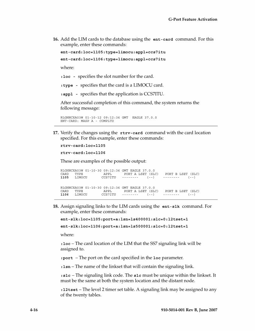
4-16 910-5014-001 Rev B, June 2007
- Draft - G-Port Feature Activation
16. Add the LIM cards to the database using the ent-card command. For this example, enter these commands:
ent-card:loc=1105:type=limocu:appl=ccs7itu
ent-card:loc=1106:type=limocu:appl=ccs7itu
where:
:loc - specifies the slot number for the card.
:type - specifies that the card is a LIMOCU card.
:appl - specifies that the application is CCS7ITU.
After successful completion of this command, the system returns the following message:
RLGHNCXA03W 01-10-12 09:12:36 GMT EAGLE 37.0.0ENT-CARD: MASP A - COMPLTD
17. Verify the changes using the rtrv-card command with the card location specified. For this example, enter these commands:
rtrv-card:loc=1105
rtrv-card:loc=1106
These are examples of the possible output:
RLGHNCXA03W 01-10-30 09:12:36 GMT EAGLE 37.0.0CARD TYPE APPL PORT A LSET (SLC) PORT B LSET (SLC)1105 LIMOCU CCS7ITU -------- (--) -------- (--)
RLGHNCXA03W 01-10-30 09:12:36 GMT EAGLE 37.0.0CARD TYPE APPL PORT A LSET (SLC) PORT B LSET (SLC)1106 LIMOCU CCS7ITU -------- (--) -------- (--)
18. Assign signaling links to the LIM cards using the ent-slk command. For example, enter these commands:
ent-slk:loc=1105:port=a:lsn=ls400001:slc=0:l2tset=1
ent-slk:loc=1106:port=a:lsn=ls500001:slc=0:l2tset=1
where:
:loc – The card location of the LIM that the SS7 signaling link will be assigned to.
:port – The port on the card specified in the loc parameter.
:lsn – The name of the linkset that will contain the signaling link.
:slc – The signaling link code. The slc must be unique within the linkset. It must be the same at both the system location and the distant node.
:l2tset – The level 2 timer set table. A signaling link may be assigned to any of the twenty tables.
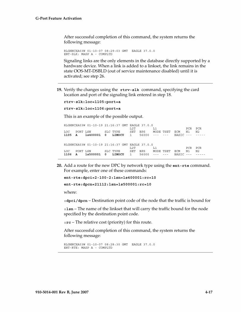
G-Port Feature Activation - Pr- Draft -elim
910-5014-001 Rev B, June 2007 4-17
After successful completion of this command, the system returns the following message:
RLGHNCXA03W 01-10-07 08:29:03 GMT EAGLE 37.0.0ENT-SLK: MASP A - COMPLTD
Signaling links are the only elements in the database directly supported by a hardware device. When a link is added to a linkset, the link remains in the state OOS-MT-DSBLD (out of service maintenance disabled) until it is activated; see step 26.
19. Verify the changes using the rtrv-slk command, specifying the card location and port of the signaling link entered in step 18.
rtrv-slk:loc=1105:port=a
rtrv-slk:loc=1106:port=a
This is an example of the possible output.
RLGHNCXA03W 01-10-19 21:16:37 GMT EAGLE 37.0.0 L2T L1 PCR PCRLOC PORT LSN SLC TYPE SET BPS MODE TSET ECM N1 N21105 A ls400001 0 LIMOCU 1 56000 --- --- BASIC --- -----
RLGHNCXA03W 01-10-19 21:16:37 GMT EAGLE 37.0.0 L2T L1 PCR PCRLOC PORT LSN SLC TYPE SET BPS MODE TSET ECM N1 N21106 A ls500001 0 LIMOCU 1 56000 --- --- BASIC --- -----
20. Add a route for the new DPC by network type using the ent-rte command. For example, enter one of these commands:
ent-rte:dpci=2-100-2:lsn=ls400001:rc=10
ent-rte:dpcn=21112:lsn=ls500001:rc=10
where:
:dpci/dpcn – Destination point code of the node that the traffic is bound for
:lsn – The name of the linkset that will carry the traffic bound for the node specified by the destination point code.
:rc – The relative cost (priority) for this route.
After successful completion of this command, the system returns the following message:
RLGHNCXA03W 01-10-07 08:28:30 GMT EAGLE 37.0.0ENT-RTE: MASP A - COMPLTD
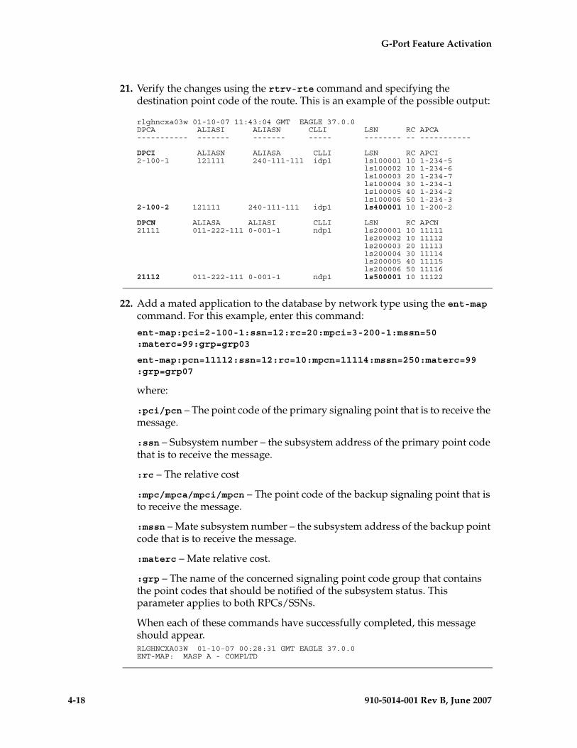
4-18 910-5014-001 Rev B, June 2007
- Draft - G-Port Feature Activation
21. Verify the changes using the rtrv-rte command and specifying the destination point code of the route. This is an example of the possible output:
rlghncxa03w 01-10-07 11:43:04 GMT EAGLE 37.0.0DPCA ALIASI ALIASN CLLI LSN RC APCA----------- ------- ------- ----- -------- -- -----------
DPCI ALIASN ALIASA CLLI LSN RC APCI2-100-1 121111 240-111-111 idp1 ls100001 10 1-234-5 ls100002 10 1-234-6 ls100003 20 1-234-7 ls100004 30 1-234-1 ls100005 40 1-234-2 ls100006 50 1-234-32-100-2 121111 240-111-111 idp1 ls400001 10 1-200-2
DPCN ALIASA ALIASI CLLI LSN RC APCN21111 011-222-111 0-001-1 ndp1 ls200001 10 11111 ls200002 10 11112 ls200003 20 11113 ls200004 30 11114 ls200005 40 11115 ls200006 50 1111621112 011-222-111 0-001-1 ndp1 ls500001 10 11122
22. Add a mated application to the database by network type using the ent-map command. For this example, enter this command:
ent-map:pci=2-100-1:ssn=12:rc=20:mpci=3-200-1:mssn=50 :materc=99:grp=grp03
ent-map:pcn=11112:ssn=12:rc=10:mpcn=11114:mssn=250:materc=99 :grp=grp07
where:
:pci/pcn – The point code of the primary signaling point that is to receive the message.
:ssn – Subsystem number – the subsystem address of the primary point code that is to receive the message.
:rc – The relative cost
:mpc/mpca/mpci/mpcn – The point code of the backup signaling point that is to receive the message.
:mssn – Mate subsystem number – the subsystem address of the backup point code that is to receive the message.
:materc – Mate relative cost.
:grp – The name of the concerned signaling point code group that contains the point codes that should be notified of the subsystem status. This parameter applies to both RPCs/SSNs.
When each of these commands have successfully completed, this message should appear.RLGHNCXA03W 01-10-07 00:28:31 GMT EAGLE 37.0.0ENT-MAP: MASP A - COMPLTD
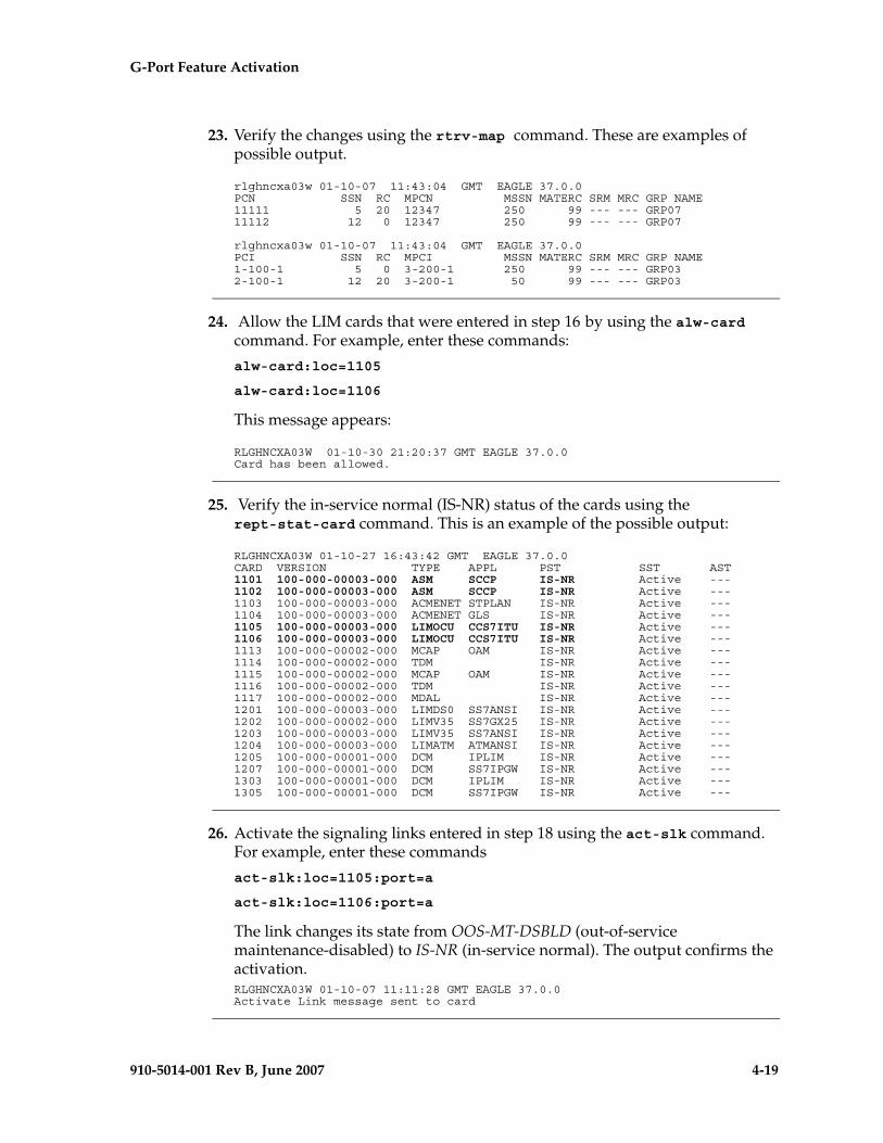
G-Port Feature Activation - Pr- Draft -elim
910-5014-001 Rev B, June 2007 4-19
23. Verify the changes using the rtrv-map command. These are examples of possible output.
rlghncxa03w 01-10-07 11:43:04 GMT EAGLE 37.0.0PCN SSN RC MPCN MSSN MATERC SRM MRC GRP NAME11111 5 20 12347 250 99 --- --- GRP0711112 12 0 12347 250 99 --- --- GRP07
rlghncxa03w 01-10-07 11:43:04 GMT EAGLE 37.0.0PCI SSN RC MPCI MSSN MATERC SRM MRC GRP NAME1-100-1 5 0 3-200-1 250 99 --- --- GRP032-100-1 12 20 3-200-1 50 99 --- --- GRP03
24. Allow the LIM cards that were entered in step 16 by using the alw-card command. For example, enter these commands:
alw-card:loc=1105
alw-card:loc=1106
This message appears:
RLGHNCXA03W 01-10-30 21:20:37 GMT EAGLE 37.0.0Card has been allowed.
25. Verify the in-service normal (IS-NR) status of the cards using the rept-stat-card command. This is an example of the possible output:
RLGHNCXA03W 01-10-27 16:43:42 GMT EAGLE 37.0.0CARD VERSION TYPE APPL PST SST AST1101 100-000-00003-000 ASM SCCP IS-NR Active ---1102 100-000-00003-000 ASM SCCP IS-NR Active ---1103 100-000-00003-000 ACMENET STPLAN IS-NR Active ---1104 100-000-00003-000 ACMENET GLS IS-NR Active ---1105 100-000-00003-000 LIMOCU CCS7ITU IS-NR Active ---1106 100-000-00003-000 LIMOCU CCS7ITU IS-NR Active ---1113 100-000-00002-000 MCAP OAM IS-NR Active ---1114 100-000-00002-000 TDM IS-NR Active ---1115 100-000-00002-000 MCAP OAM IS-NR Active ---1116 100-000-00002-000 TDM IS-NR Active ---1117 100-000-00002-000 MDAL IS-NR Active ---1201 100-000-00003-000 LIMDS0 SS7ANSI IS-NR Active ---1202 100-000-00002-000 LIMV35 SS7GX25 IS-NR Active ---1203 100-000-00003-000 LIMV35 SS7ANSI IS-NR Active ---1204 100-000-00003-000 LIMATM ATMANSI IS-NR Active ---1205 100-000-00001-000 DCM IPLIM IS-NR Active ---1207 100-000-00001-000 DCM SS7IPGW IS-NR Active ---1303 100-000-00001-000 DCM IPLIM IS-NR Active ---1305 100-000-00001-000 DCM SS7IPGW IS-NR Active ---
26. Activate the signaling links entered in step 18 using the act-slk command. For example, enter these commands
act-slk:loc=1105:port=a
act-slk:loc=1106:port=a
The link changes its state from OOS-MT-DSBLD (out-of-service maintenance-disabled) to IS-NR (in-service normal). The output confirms the activation.RLGHNCXA03W 01-10-07 11:11:28 GMT EAGLE 37.0.0Activate Link message sent to card
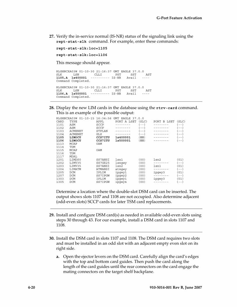
4-20 910-5014-001 Rev B, June 2007
- Draft - G-Port Feature Activation
27. Verify the in-service normal (IS-NR) status of the signaling link using the rept-stat-slk command. For example, enter these commands:
rept-stat-slk:loc=1105
rept-stat-slk:loc=1106
This message should appear.
RLGHNCXA03W 01-10-30 21:16:37 GMT EAGLE 37.0.0SLK LSN CLLI PST SST AST1105,A ls400001 ---------- IS-NR Avail ----Command Completed.
RLGHNCXA03W 01-10-30 21:16:37 GMT EAGLE 37.0.0SLK LSN CLLI PST SST AST1106,A ls500001 ---------- IS-NR Avail ----Command Completed.
28. Display the new LIM cards in the database using the rtrv-card command. This is an example of the possible output:RLGHNCXA03W 01-10-15 16:34:56 GMT EAGLE 37.0.0CARD TYPE APPL PORT A LSET (SLC) PORT B LSET (SLC)1101 ASM SCCP -------- (--) -------- (--)1102 ASM SCCP -------- (--) -------- (--)1103 ACMENET STPLAN -------- (--) -------- (--)1104 ACMENET GLS -------- (--) -------- (--)1105 LIMOCU CCS7ITU ls400001 (00) -------- (--)1106 LIMOCU CCS7ITU ls500001 (00) -------- (--)1113 MCAP OAM1114 TDM1115 MCAP OAM1116 TDM1117 MDAL1201 LIMDS0 SS7ANSI lsn1 (00) lsn2 (01)1202 LIMV35 SS7GX25 lsngwy (00) -------- (--)1203 LIMV35 SS7ANSI lsn2 (00) lsn1 (01)1204 LIMATM ATMANSI atmgwy (00) -------- (--)1205 DCM IPLIM ipgwy1 (00) ipgwy3 (01)1207 DCM SS7IPGW ipgwy2 (00) -------- (--)1303 DCM IPLIM ipgwy1 (00) ipgwy3 (01)1305 DCM SS7IPGW ipgwy4 (00) -------- (--)
Determine a location where the double-slot DSM card can be inserted. The output shows slots 1107 and 1108 are not occupied. Also determine adjacent (odd-even slots) SCCP cards for later TSM card replacements.
29. Install and configure DSM card(s) as needed in available odd-even slots using steps 30 through 43. For our example, install a DSM card in slots 1107 and 1108.
30. Install the DSM card in slots 1107 and 1108. The DSM card requires two slots and must be installed in an odd slot with an adjacent empty even slot on its right side.
a. Open the ejector levers on the DSM card. Carefully align the card’s edges with the top and bottom card guides. Then push the card along the length of the card guides until the rear connectors on the card engage the mating connectors on the target shelf backplane.
G-Port Feature Activation - Pr- Draft -elim
910-5014-001 Rev B, June 2007 4-21
b. Press the left edge of the card’s faceplate using constant pressure until you feel the card’s progress cease.
WARNING: Do not impact the faceplate in order to mate the connectors. Any impact to the card’s faceplate can damage the faceplate, the pins, or the connectors.
c. Push in the top and bottom inject/eject clamps. This locks the card in place and ensures a strong connection with the pins on the target shelf backplane.
Figure 4-1. Push in Inject/Eject Clamps
d. Verify that both IMT bus LEDs are green.
e. Install the cabling required to connect the DSM card to the MPS. Refer to the Installation Manual for details.
31. Add the DSM card to the database and configure it as VSCCP card using the ent-card command. For this example, enter this command.
ent-card:loc=1107:type=dsm:appl=vsccp
where:
:loc - specifies the slot number for the card. The slot number must be an odd number.
:type - specifies that the card is a DSM card.
:appl - specifies that the application is VSCCP.
After successful completion of this command, the system returns the following message:
Push in the inject/eject clamps to lock the card in place.
4-22 910-5014-001 Rev B, June 2007
- Draft - G-Port Feature Activation
RLGHNCXA03W 01-10-12 09:12:36 GMT EAGLE 37.0.0ENT-CARD: MASP A - COMPLTD
32. Verify the VSCCP card using the rtrv-card command with the card location specified. For this example, enter this command:
rtrv-card:loc=1107
This is an example of the possible output:
RLGHNCXA03W 01-10-30 09:12:36 GMT EAGLE 37.0.0CARD TYPE APPL PORT A LSET (SLC) PORT B LSET (SLC)1107 DSM VSCCP -------- (--) -------- (--)
33. Display the current link parameters associated with the VSCCP card in the database by entering the rtrv-ip-lnk command. This is an example of the possible output:
RLGHNCXA03W 01-10-30 21:14:37 GMT EAGLE 37.0.0 LOC PORT IPADDR SUBMASK DUPLEX SPEED MACTYPE AUTO MCAST1107 A ----------- ----------- HALF 10 DIX NO NO1107 B ----------- ----------- HALF 10 DIX NO NO
34. Enter the IP address port and speed associated with the VSCCP card in the database using the chg-ip-lnk command. For this example, enter these commands:
chg-ip-lnk:loc=1107:port=a:duplex=half:ipaddrr=192.168.122.1 :mactype=dix:speed=100:mcast=yes:submask=255.255.255.0
chg-ip-lnk:loc=1107:port=b:duplex=half:ipaddrr=192.168.123.1 :mactype=dix:speed=10:mcast=yes:submask=255.255.255.0
where:
:loc – The card location of the VSCCP card within the EAGLE 5 ISS.
:port – The port ID. The port parameter of the chg-ip-lnk command specifies the physical interface of the DSM card.
:ipaddr – IP address assigned to the port. This is a TCP/IP address expressed in standard “dot notation.” IP addresses consist of the system’s network number and the machine’s unique host number.
:duplex – This is the mode of operation of the interface.
:speed – This is interface bandwidth in megabits per second. The speed is either 100 Mbps for main DSM network or 10 Mbps for backup DSM network.
:mactype – This is the Media Access Control Type of the interface. Specify dix for the Digital/Inter/Xerox de facto standard for the Ethernet.
:mcast – This is the Multicast Control of the interface.
:submask – The subnet mask of the IP interface, in the form of an IP address with a restricted range of values.
G-Port Feature Activation - Pr- Draft -elim
910-5014-001 Rev B, June 2007 4-23
When this command has successfully completed, the following message appears:
RLGHNCXA03W 01-10-30 21:18:37 GMT EAGLE 37.0.0CHG-IP-LNK: MASP A - COMPLTD
35. Verify the IP address port and speed associated with the VSCCP card in the database by entering the rtrv-ip-lnk command. This is an example of the possible output:
RLGHNCXA03W 01-10-30 21:14:37 GMT EAGLE 37.0.0 LOC PORT IPADDR SUBMASK DUPLEX SPEED MACTYPE AUTO MCAST1107 A 192.168.122.1 255.255.255.0 HALF 100 DIX NO YES1107 B 192.168.123.1 255.255.255.0 HALF 10 DIX NO YES
36. Display the current IP host information in the database by entering the rtrv-ip-host command. This is an example of the possible output:
RLGHNCXA03W 01-10-30 21:17:37 GMT EAGLE 37.0.0
IPADDR HOST192.1.1.32 KC_HLR2192.1.1.50 DN_MSC1192.1.1.52 DN_MSC2
37. Add the host name and IP address for each VSCCP link using the ent-ip-host command. For example, enter these commands:
ent-ip-host:host=vsccp_1107_a:ipaddr=192.168.122.1
ent-ip-host:host=vsccp_1107_b:ipaddr=192.168.123.1
where:
:host - specifies the host name. Each VSCCP link must be specified separately.
:ipaddr - specifies the IP network address for each EPAP. The first three octets of the IP address must be the same as MPS A and B ports, respectively. The fourth octet identifies the DSM card and must have a a unique octet identifier for the card’s IP address; we recommend numbering the DSM cards sequentially, using values 1 to 25. (This example shows the assignment of the first DSM card.)
After successful completion of this command, the system returns the following message:RLGHNCXA03W 01-10-30 21:18:37 GMT EAGLE 37.0.0ENT-IP-HOST: MASP A - COMPLTD
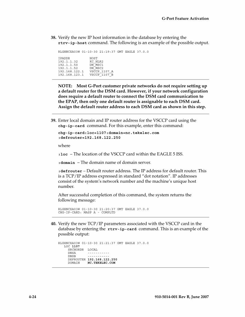
4-24 910-5014-001 Rev B, June 2007
- Draft - G-Port Feature Activation
38. Verify the new IP host information in the database by entering the rtrv-ip-host command. The following is an example of the possible output.
RLGHNCXA03W 01-10-30 21:19:37 GMT EAGLE 37.0.0
IPADDR HOST192.1.1.32 KC_HLR2192.1.1.50 DN_MSC1192.1.1.52 DN_MSC2192.168.122.1 VSCCP_1107_A192.168.123.1 VSCCP_1107_B
NOTE: Most G-Port customer private networks do not require setting up a default router for the DSM card. However, if your network configuration does require a default router to connect the DSM card communication to the EPAP, then only one default router is assignable to each DSM card. Assign the default router address to each DSM card as shown in this step.
39. Enter local domain and IP router address for the VSCCP card using the chg-ip-card command. For this example, enter this command:
chg-ip-card:loc=1107:domain=nc.tekelec.com :defrouter=192.168.122.250
where
:loc – The location of the VSCCP card within the EAGLE 5 ISS.
:domain – The domain name of domain server.
:defrouter – Default router address. The IP address for default router. This is a TCP/IP address expressed in standard “dot notation”. IP addresses consist of the system’s network number and the machine’s unique host number.
After successful completion of this command, the system returns the following message:
RLGHNCXA03W 01-10-30 21:20:37 GMT EAGLE 37.0.0CHG-IP-CARD: MASP A - COMPLTD
40. Verify the new TCP/IP parameters associated with the VSCCP card in the database by entering the rtrv-ip-card command. This is an example of the possible output:
RLGHNCXA03W 01-10-30 21:21:37 GMT EAGLE 37.0.0 LOC 1107 SRCHORDR LOCAL DNSA ----------- DNSB ----------- DEFROUTER 192.168.122.250 DOMAIN NC.TEKELEC.COM
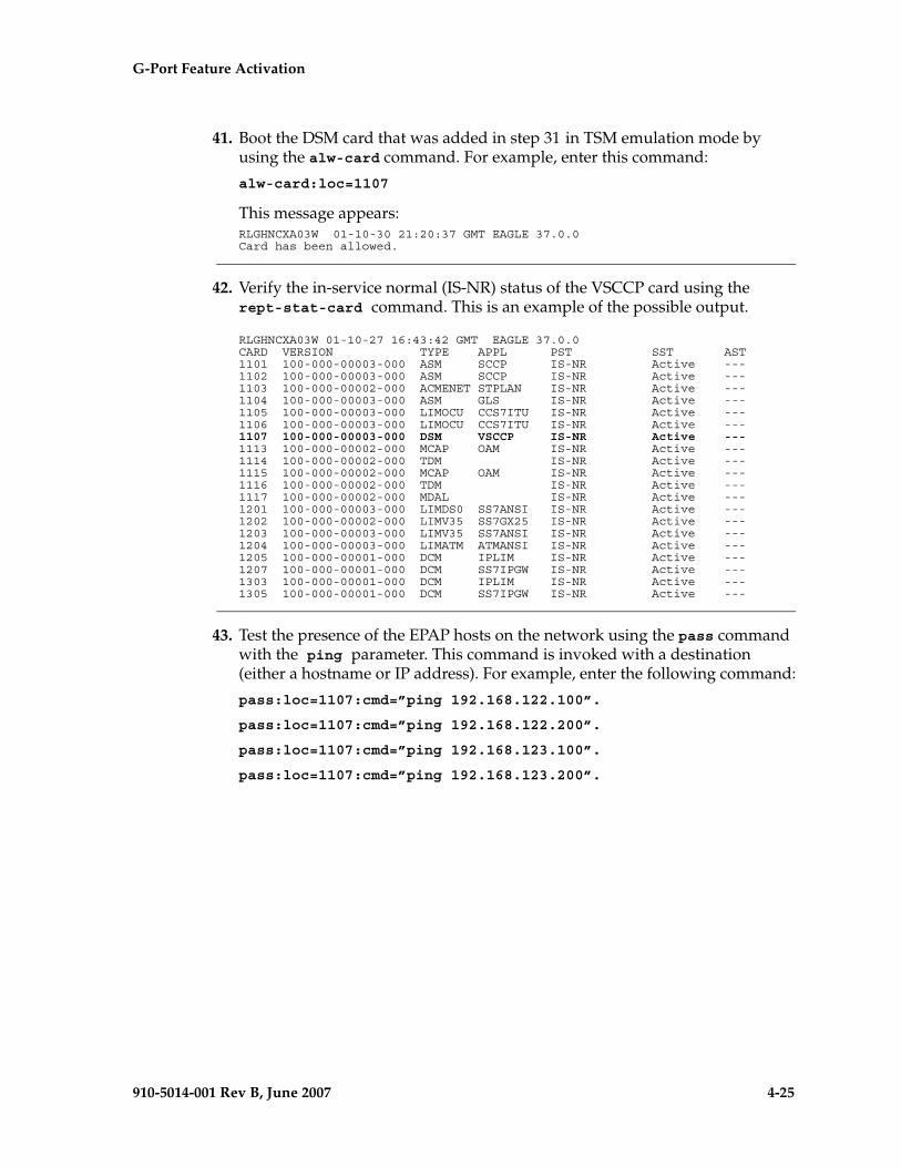
G-Port Feature Activation - Pr- Draft -elim
910-5014-001 Rev B, June 2007 4-25
41. Boot the DSM card that was added in step 31 in TSM emulation mode by using the alw-card command. For example, enter this command:
alw-card:loc=1107
This message appears:RLGHNCXA03W 01-10-30 21:20:37 GMT EAGLE 37.0.0Card has been allowed.
42. Verify the in-service normal (IS-NR) status of the VSCCP card using the rept-stat-card command. This is an example of the possible output.
RLGHNCXA03W 01-10-27 16:43:42 GMT EAGLE 37.0.0CARD VERSION TYPE APPL PST SST AST1101 100-000-00003-000 ASM SCCP IS-NR Active ---1102 100-000-00003-000 ASM SCCP IS-NR Active ---1103 100-000-00002-000 ACMENET STPLAN IS-NR Active ---1104 100-000-00003-000 ASM GLS IS-NR Active ---1105 100-000-00003-000 LIMOCU CCS7ITU IS-NR Active ---1106 100-000-00003-000 LIMOCU CCS7ITU IS-NR Active ---1107 100-000-00003-000 DSM VSCCP IS-NR Active ---1113 100-000-00002-000 MCAP OAM IS-NR Active ---1114 100-000-00002-000 TDM IS-NR Active ---1115 100-000-00002-000 MCAP OAM IS-NR Active ---1116 100-000-00002-000 TDM IS-NR Active ---1117 100-000-00002-000 MDAL IS-NR Active ---1201 100-000-00003-000 LIMDS0 SS7ANSI IS-NR Active ---1202 100-000-00002-000 LIMV35 SS7GX25 IS-NR Active ---1203 100-000-00003-000 LIMV35 SS7ANSI IS-NR Active ---1204 100-000-00003-000 LIMATM ATMANSI IS-NR Active ---1205 100-000-00001-000 DCM IPLIM IS-NR Active ---1207 100-000-00001-000 DCM SS7IPGW IS-NR Active ---1303 100-000-00001-000 DCM IPLIM IS-NR Active ---1305 100-000-00001-000 DCM SS7IPGW IS-NR Active ---
43. Test the presence of the EPAP hosts on the network using the pass command with the ping parameter. This command is invoked with a destination (either a hostname or IP address). For example, enter the following command:
pass:loc=1107:cmd=”ping 192.168.122.100”.
pass:loc=1107:cmd=”ping 192.168.122.200”.
pass:loc=1107:cmd=”ping 192.168.123.100”.
pass:loc=1107:cmd=”ping 192.168.123.200”.
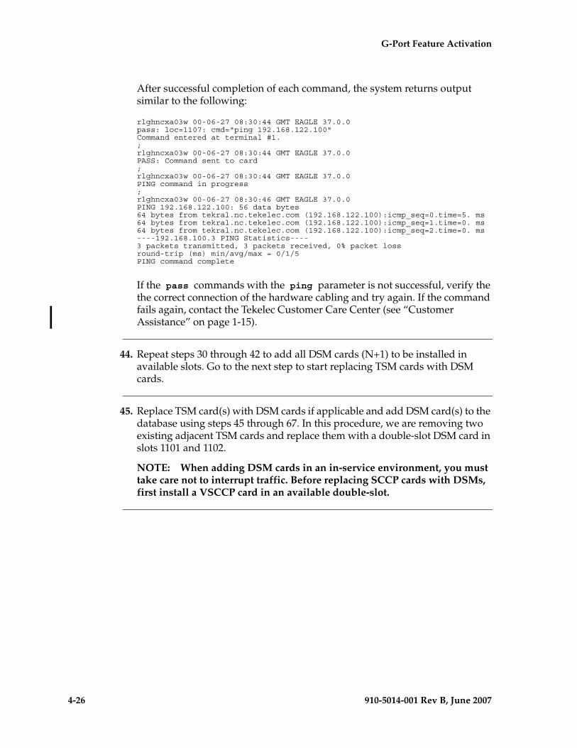
4-26 910-5014-001 Rev B, June 2007
- Draft - G-Port Feature Activation
After successful completion of each command, the system returns output similar to the following:
rlghncxa03w 00-06-27 08:30:44 GMT EAGLE 37.0.0pass: loc=1107: cmd="ping 192.168.122.100"Command entered at terminal #1.;rlghncxa03w 00-06-27 08:30:44 GMT EAGLE 37.0.0PASS: Command sent to card;rlghncxa03w 00-06-27 08:30:44 GMT EAGLE 37.0.0PING command in progress;rlghncxa03w 00-06-27 08:30:46 GMT EAGLE 37.0.0PING 192.168.122.100: 56 data bytes64 bytes from tekral.nc.tekelec.com (192.168.122.100):icmp_seq=0.time=5. ms64 bytes from tekral.nc.tekelec.com (192.168.122.100):icmp_seq=1.time=0. ms64 bytes from tekral.nc.tekelec.com (192.168.122.100):icmp_seq=2.time=0. ms----192.168.100.3 PING Statistics----3 packets transmitted, 3 packets received, 0% packet lossround-trip (ms) min/avg/max = 0/1/5PING command complete
If the pass commands with the ping parameter is not successful, verify the the correct connection of the hardware cabling and try again. If the command fails again, contact the Tekelec Customer Care Center (see “Customer Assistance” on page 1-15).
44. Repeat steps 30 through 42 to add all DSM cards (N+1) to be installed in available slots. Go to the next step to start replacing TSM cards with DSM cards.
45. Replace TSM card(s) with DSM cards if applicable and add DSM card(s) to the database using steps 45 through 67. In this procedure, we are removing two existing adjacent TSM cards and replace them with a double-slot DSM card in slots 1101 and 1102.
NOTE: When adding DSM cards in an in-service environment, you must take care not to interrupt traffic. Before replacing SCCP cards with DSMs, first install a VSCCP card in an available double-slot.
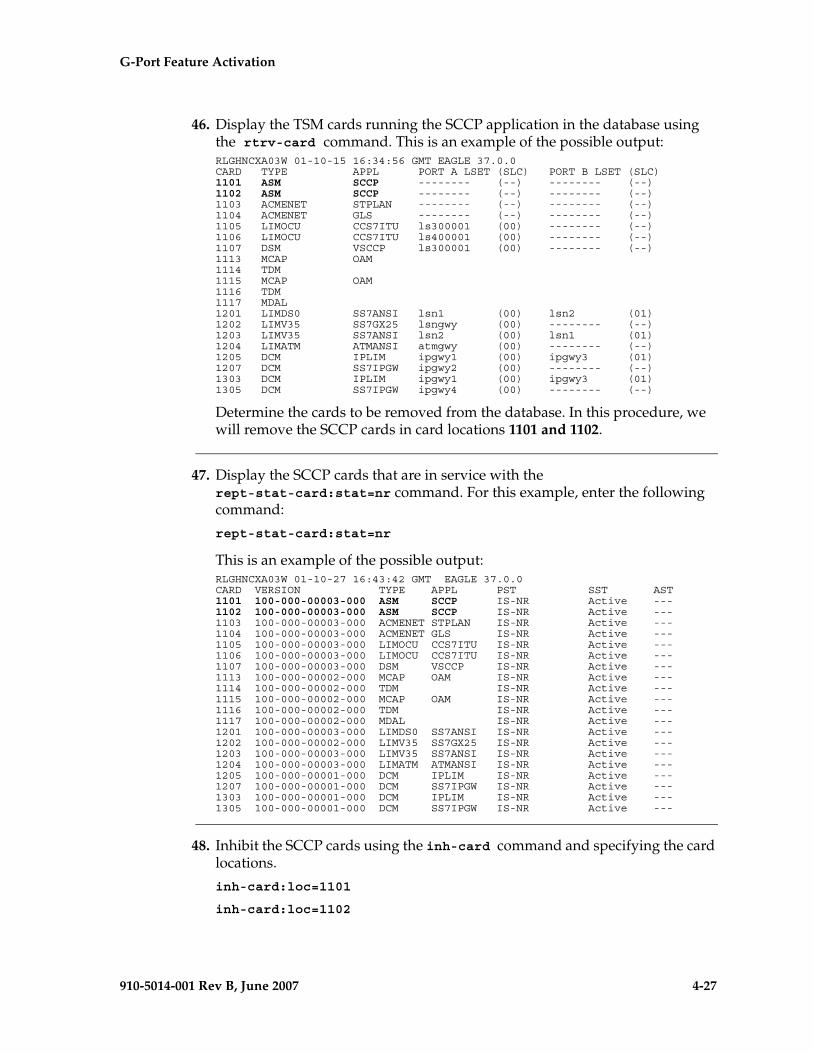
G-Port Feature Activation - Pr- Draft -elim
910-5014-001 Rev B, June 2007 4-27
46. Display the TSM cards running the SCCP application in the database using the rtrv-card command. This is an example of the possible output:RLGHNCXA03W 01-10-15 16:34:56 GMT EAGLE 37.0.0CARD TYPE APPL PORT A LSET (SLC) PORT B LSET (SLC)1101 ASM SCCP -------- (--) -------- (--)1102 ASM SCCP -------- (--) -------- (--)1103 ACMENET STPLAN -------- (--) -------- (--)1104 ACMENET GLS -------- (--) -------- (--)1105 LIMOCU CCS7ITU ls300001 (00) -------- (--)1106 LIMOCU CCS7ITU ls400001 (00) -------- (--)1107 DSM VSCCP ls300001 (00) -------- (--)1113 MCAP OAM1114 TDM1115 MCAP OAM1116 TDM1117 MDAL1201 LIMDS0 SS7ANSI lsn1 (00) lsn2 (01)1202 LIMV35 SS7GX25 lsngwy (00) -------- (--)1203 LIMV35 SS7ANSI lsn2 (00) lsn1 (01)1204 LIMATM ATMANSI atmgwy (00) -------- (--)1205 DCM IPLIM ipgwy1 (00) ipgwy3 (01)1207 DCM SS7IPGW ipgwy2 (00) -------- (--)1303 DCM IPLIM ipgwy1 (00) ipgwy3 (01)1305 DCM SS7IPGW ipgwy4 (00) -------- (--)
Determine the cards to be removed from the database. In this procedure, we will remove the SCCP cards in card locations 1101 and 1102.
47. Display the SCCP cards that are in service with the rept-stat-card:stat=nr command. For this example, enter the following command:
rept-stat-card:stat=nr
This is an example of the possible output:RLGHNCXA03W 01-10-27 16:43:42 GMT EAGLE 37.0.0CARD VERSION TYPE APPL PST SST AST1101 100-000-00003-000 ASM SCCP IS-NR Active ---1102 100-000-00003-000 ASM SCCP IS-NR Active ---1103 100-000-00003-000 ACMENET STPLAN IS-NR Active ---1104 100-000-00003-000 ACMENET GLS IS-NR Active ---1105 100-000-00003-000 LIMOCU CCS7ITU IS-NR Active ---1106 100-000-00003-000 LIMOCU CCS7ITU IS-NR Active ---1107 100-000-00003-000 DSM VSCCP IS-NR Active ---1113 100-000-00002-000 MCAP OAM IS-NR Active ---1114 100-000-00002-000 TDM IS-NR Active ---1115 100-000-00002-000 MCAP OAM IS-NR Active ---1116 100-000-00002-000 TDM IS-NR Active ---1117 100-000-00002-000 MDAL IS-NR Active ---1201 100-000-00003-000 LIMDS0 SS7ANSI IS-NR Active ---1202 100-000-00002-000 LIMV35 SS7GX25 IS-NR Active ---1203 100-000-00003-000 LIMV35 SS7ANSI IS-NR Active ---1204 100-000-00003-000 LIMATM ATMANSI IS-NR Active ---1205 100-000-00001-000 DCM IPLIM IS-NR Active ---1207 100-000-00001-000 DCM SS7IPGW IS-NR Active ---1303 100-000-00001-000 DCM IPLIM IS-NR Active ---1305 100-000-00001-000 DCM SS7IPGW IS-NR Active ---
48. Inhibit the SCCP cards using the inh-card command and specifying the card locations.
inh-card:loc=1101
inh-card:loc=1102
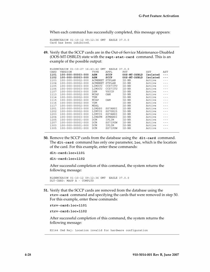
4-28 910-5014-001 Rev B, June 2007
- Draft - G-Port Feature Activation
When each command has successfully completed, this message appears:
RLGHNCXA03W 01-10-12 09:12:36 GMT EAGLE 37.0.0Card has been inhibited.
49. Verify that the SCCP cards are in the Out-of-Service Maintenance-Disabled (OOS-MT-DSBLD) state with the rept-stat-card command. This is an example of the possible output:
RLGHNCXA03W 01-10-27 16:43:42 GMT EAGLE 37.0.0CARD VERSION TYPE APPL PST SST AST1101 100-000-00003-000 ASM SCCP OOS-MT-DSBLD Isolated ---1102 100-000-00003-000 ASM SCCP OOS-MT-DSBLD Isolated ---1103 100-000-00002-000 ACMENET STPLAN IS-NR Active ---1104 100-000-00002-000 ACMENET STPLAN IS-NR Active ---1105 100-000-00003-000 LIMOCU CCS7ITU IS-NR Active ---1106 100-000-00003-000 LIMOCU CCS7ITU IS-NR Active ---1107 100-000-00003-000 DSM VSCCP IS-NR Active ---1113 100-000-00002-000 MCAP OAM IS-NR Active ---1114 100-000-00002-000 TDM IS-NR Active ---1115 100-000-00002-000 MCAP OAM IS-NR Active ---1116 100-000-00002-000 TDM IS-NR Active ---1117 100-000-00002-000 MDAL IS-NR Active ---1201 100-000-00003-000 LIMDS0 SS7ANSI IS-NR Active ---1202 100-000-00002-000 LIMV35 SS7GX25 IS-NR Active ---1203 100-000-00003-000 LIMV35 SS7ANSI IS-NR Active ---1204 100-000-00003-000 LIMATM ATMANSI IS-NR Active ---1205 100-000-00001-000 DCM IPLIM IS-NR Active ---1207 100-000-00001-000 DCM SS7IPGW IS-NR Active ---1303 100-000-00001-000 DCM IPLIM IS-NR Active ---1305 100-000-00001-000 DCM SS7IPGW IS-NR Active ---
50. Remove the SCCP cards from the database using the dlt-card command. The dlt-card command has only one parameter, loc, which is the location of the card. For this example, enter these commands:
dlt-card:loc=1101
dlt-card:loc=1102
After successful completion of this command, the system returns the following message:
RLGHNCXA03W 01-10-12 09:12:36 GMT EAGLE 37.0.0DLT-CARD: MASP A - COMPLTD
51. Verify that the SCCP cards are removed from the database using the rtrv-card command and specifying the cards that were removed in step 50. For this example, enter these commands:
rtrv-card:loc=1101
rtrv-card:loc=1102
After successful completion of this command, the system returns the following message:
E2144 Cmd Rej: Location invalid for hardware configuration
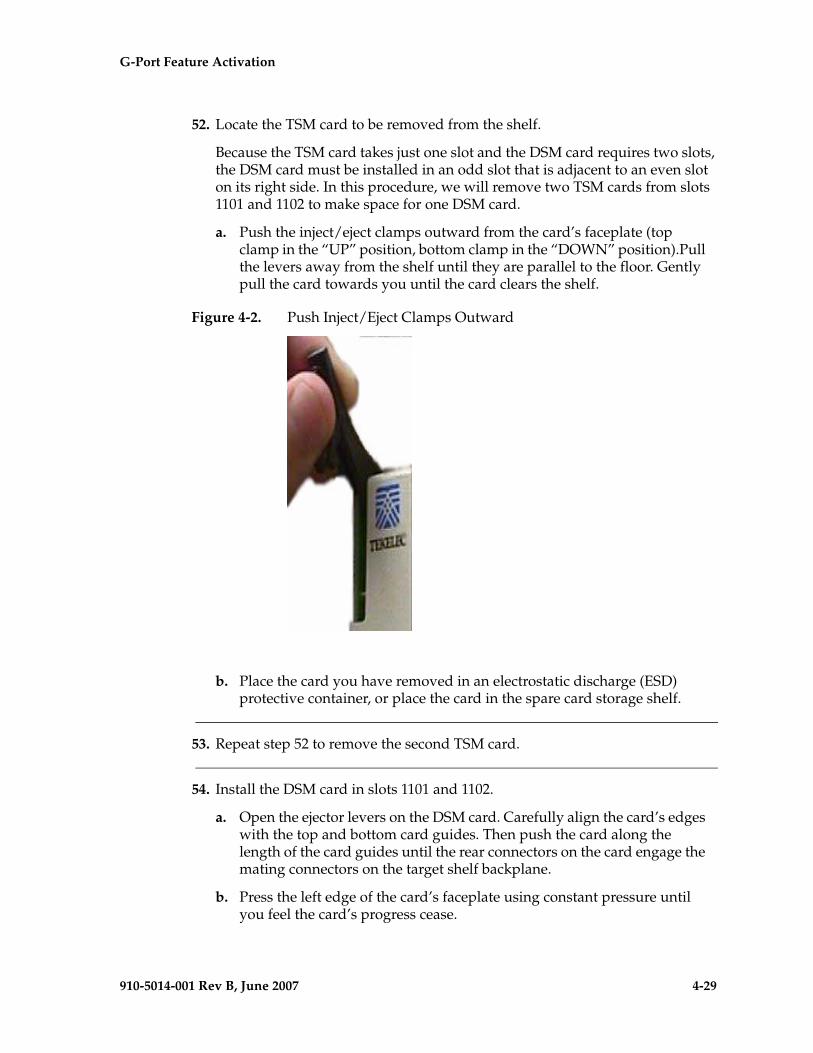
G-Port Feature Activation - Pr- Draft -elim
910-5014-001 Rev B, June 2007 4-29
52. Locate the TSM card to be removed from the shelf.
Because the TSM card takes just one slot and the DSM card requires two slots, the DSM card must be installed in an odd slot that is adjacent to an even slot on its right side. In this procedure, we will remove two TSM cards from slots 1101 and 1102 to make space for one DSM card.
a. Push the inject/eject clamps outward from the card’s faceplate (top clamp in the “UP” position, bottom clamp in the “DOWN” position).Pull the levers away from the shelf until they are parallel to the floor. Gently pull the card towards you until the card clears the shelf.
Figure 4-2. Push Inject/Eject Clamps Outward
b. Place the card you have removed in an electrostatic discharge (ESD) protective container, or place the card in the spare card storage shelf.
53. Repeat step 52 to remove the second TSM card.
54. Install the DSM card in slots 1101 and 1102.
a. Open the ejector levers on the DSM card. Carefully align the card’s edges with the top and bottom card guides. Then push the card along the length of the card guides until the rear connectors on the card engage the mating connectors on the target shelf backplane.
b. Press the left edge of the card’s faceplate using constant pressure until you feel the card’s progress cease.
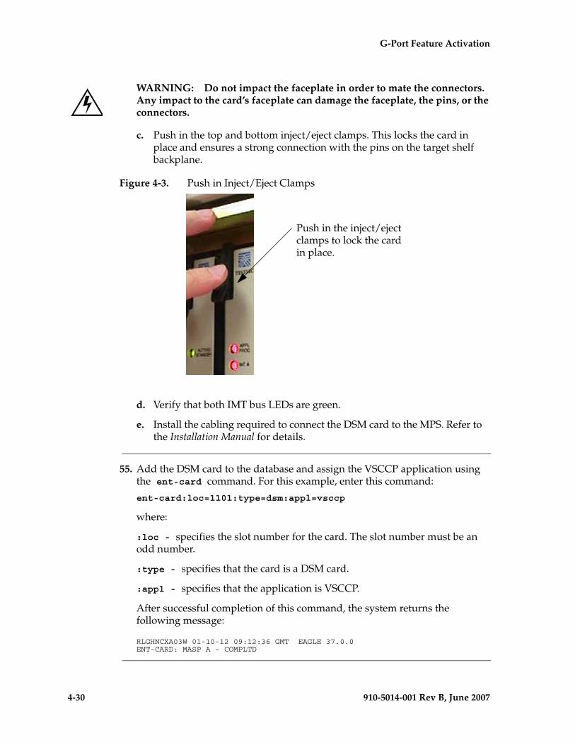
4-30 910-5014-001 Rev B, June 2007
- Draft - G-Port Feature Activation
WARNING: Do not impact the faceplate in order to mate the connectors. Any impact to the card’s faceplate can damage the faceplate, the pins, or the connectors.
c. Push in the top and bottom inject/eject clamps. This locks the card in place and ensures a strong connection with the pins on the target shelf backplane.
Figure 4-3. Push in Inject/Eject Clamps
d. Verify that both IMT bus LEDs are green.
e. Install the cabling required to connect the DSM card to the MPS. Refer to the Installation Manual for details.
55. Add the DSM card to the database and assign the VSCCP application using the ent-card command. For this example, enter this command:
ent-card:loc=1101:type=dsm:appl=vsccp
where:
:loc - specifies the slot number for the card. The slot number must be an odd number.
:type - specifies that the card is a DSM card.
:appl - specifies that the application is VSCCP.
After successful completion of this command, the system returns the following message:
RLGHNCXA03W 01-10-12 09:12:36 GMT EAGLE 37.0.0ENT-CARD: MASP A - COMPLTD
Push in the inject/eject clamps to lock the card in place.
G-Port Feature Activation - Pr- Draft -elim
910-5014-001 Rev B, June 2007 4-31
56. Display the new VSCCP card using the rtrv-card command with the card location specified. For this example, enter this command:
rtrv-card:loc=1101
This is an example of the possible output:
RLGHNCXA03W 01-10-30 09:12:36 GMT EAGLE 37.0.0CARD TYPE APPL PORT A LSET (SLC) PORT B LSET (SLC)1101 DSM VSCCP -------- (--) -------- (--)
57. Display the current link parameters associated with the VSCCP card in the database by entering the rtrv-ip-lnk command. This is an example of the possible output:
RLGHNCXA03W 01-10-30 21:14:37 GMT EAGLE 37.0.0 LOC PORT IPADDR SUBMASK DUPLEX SPEED MACTYPE AUTO MCAST1101 A ----------- ----------- HALF 10 DIX NO NO1101 B ----------- ----------- HALF 10 DIX NO NO1107 A ----------- ----------- HALF 10 DIX NO NO1107 B ----------- ----------- HALF 10 DIX NO NO
58. Change the link parameters associated with the VSCCP card in the database using the chg-ip-lnk command. For this example, enter these commands:
chg-ip-lnk:loc=1101:port=a:duplex=half:ipaddrr=192.168.122.2 :mactype=dix:speed=100:mcast=yes:submask=255.255.255.0
chg-ip-lnk:loc=1101:port=b:duplex=half:ipaddrr=192.168.123.2 :mactype=dix:speed=10:mcast=yes:submask=255.255.255.0
where:
:loc – The card location of the card within the EAGLE 5 ISS.
:port – The port ID. The port parameter of the chg-ip-lnk command specifies the physical interface of the DSM card.
:ipaddr – IP address assigned to the port. This is a TCP/IP address expressed in standard “dot notation.” IP addresses consist of the system’s network number and the machine’s unique host number.
:duplex – This is the mode of operation of the interface.
:speed – This is interface bandwidth in megabits per second. The speed is either 100 Mbps for main DSM network or 10 Mbps for backup DSM network.
:mactype – This is the Media Access Control Type of the interface. Specify dix for the Digital/Inter/Xerox de facto standard for the Ethernet.
:mcast – This is the Multicast Control of the interface.
:submask – The subnet mask of the IP interface, in the form of an IP address with a restricted range of values.
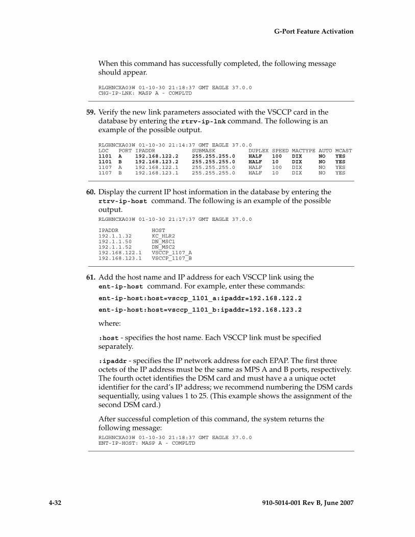
4-32 910-5014-001 Rev B, June 2007
- Draft - G-Port Feature Activation
When this command has successfully completed, the following message should appear.
RLGHNCXA03W 01-10-30 21:18:37 GMT EAGLE 37.0.0CHG-IP-LNK: MASP A - COMPLTD
59. Verify the new link parameters associated with the VSCCP card in the database by entering the rtrv-ip-lnk command. The following is an example of the possible output.
RLGHNCXA03W 01-10-30 21:14:37 GMT EAGLE 37.0.0 LOC PORT IPADDR SUBMASK DUPLEX SPEED MACTYPE AUTO MCAST1101 A 192.168.122.2 255.255.255.0 HALF 100 DIX NO YES1101 B 192.168.123.2 255.255.255.0 HALF 10 DIX NO YES1107 A 192.168.122.1 255.255.255.0 HALF 100 DIX NO YES1107 B 192.168.123.1 255.255.255.0 HALF 10 DIX NO YES
60. Display the current IP host information in the database by entering the rtrv-ip-host command. The following is an example of the possible output.RLGHNCXA03W 01-10-30 21:17:37 GMT EAGLE 37.0.0
IPADDR HOST192.1.1.32 KC_HLR2192.1.1.50 DN_MSC1192.1.1.52 DN_MSC2192.168.122.1 VSCCP_1107_A192.168.123.1 VSCCP_1107_B
61. Add the host name and IP address for each VSCCP link using the ent-ip-host command. For example, enter these commands:
ent-ip-host:host=vsccp_1101_a:ipaddr=192.168.122.2
ent-ip-host:host=vsccp_1101_b:ipaddr=192.168.123.2
where:
:host - specifies the host name. Each VSCCP link must be specified separately.
:ipaddr - specifies the IP network address for each EPAP. The first three octets of the IP address must be the same as MPS A and B ports, respectively. The fourth octet identifies the DSM card and must have a a unique octet identifier for the card’s IP address; we recommend numbering the DSM cards sequentially, using values 1 to 25. (This example shows the assignment of the second DSM card.)
After successful completion of this command, the system returns the following message:RLGHNCXA03W 01-10-30 21:18:37 GMT EAGLE 37.0.0ENT-IP-HOST: MASP A - COMPLTD
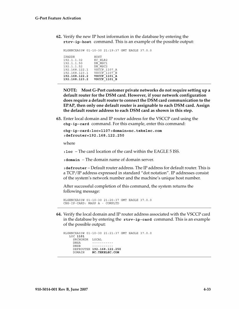
G-Port Feature Activation - Pr- Draft -elim
910-5014-001 Rev B, June 2007 4-33
62. Verify the new IP host information in the database by entering the rtrv-ip-host command. This is an example of the possible output:
RLGHNCXA03W 01-10-30 21:19:37 GMT EAGLE 37.0.0
IPADDR HOST192.1.1.32 KC_HLR2192.1.1.50 DN_MSC1192.1.1.52 DN_MSC2192.168.122.1 VSCCP_1107_A192.168.123.1 VSCCP_1107_B192.168.122.2 VSCCP_1101_A192.168.123.2 VSCCP_1101_B
NOTE: Most G-Port customer private networks do not require setting up a default router for the DSM card. However, if your network configuration does require a default router to connect the DSM card communication to the EPAP, then only one default router is assignable to each DSM card. Assign the default router address to each DSM card as shown in this step.
63. Enter local domain and IP router address for the VSCCP card using the chg-ip-card command. For this example, enter this command:
chg-ip-card:loc=1107:domain=nc.tekelec.com :defrouter=192.168.122.250
where
:loc – The card location of the card within the EAGLE 5 ISS.
:domain – The domain name of domain server.
:defrouter – Default router address. The IP address for default router. This is a TCP/IP address expressed in standard “dot notation”. IP addresses consist of the system’s network number and the machine’s unique host number.
After successful completion of this command, the system returns the following message:
RLGHNCXA03W 01-10-30 21:20:37 GMT EAGLE 37.0.0CHG-IP-CARD: MASP A - COMPLTD
64. Verify the local domain and IP router address associated with the VSCCP card in the database by entering the rtrv-ip-card command. This is an example of the possible output:
RLGHNCXA03W 01-10-30 21:21:37 GMT EAGLE 37.0.0 LOC 1101 SRCHORDR LOCAL DNSA ----------- DNSB ----------- DEFROUTER 192.168.122.250 DOMAIN NC.TEKELEC.COM
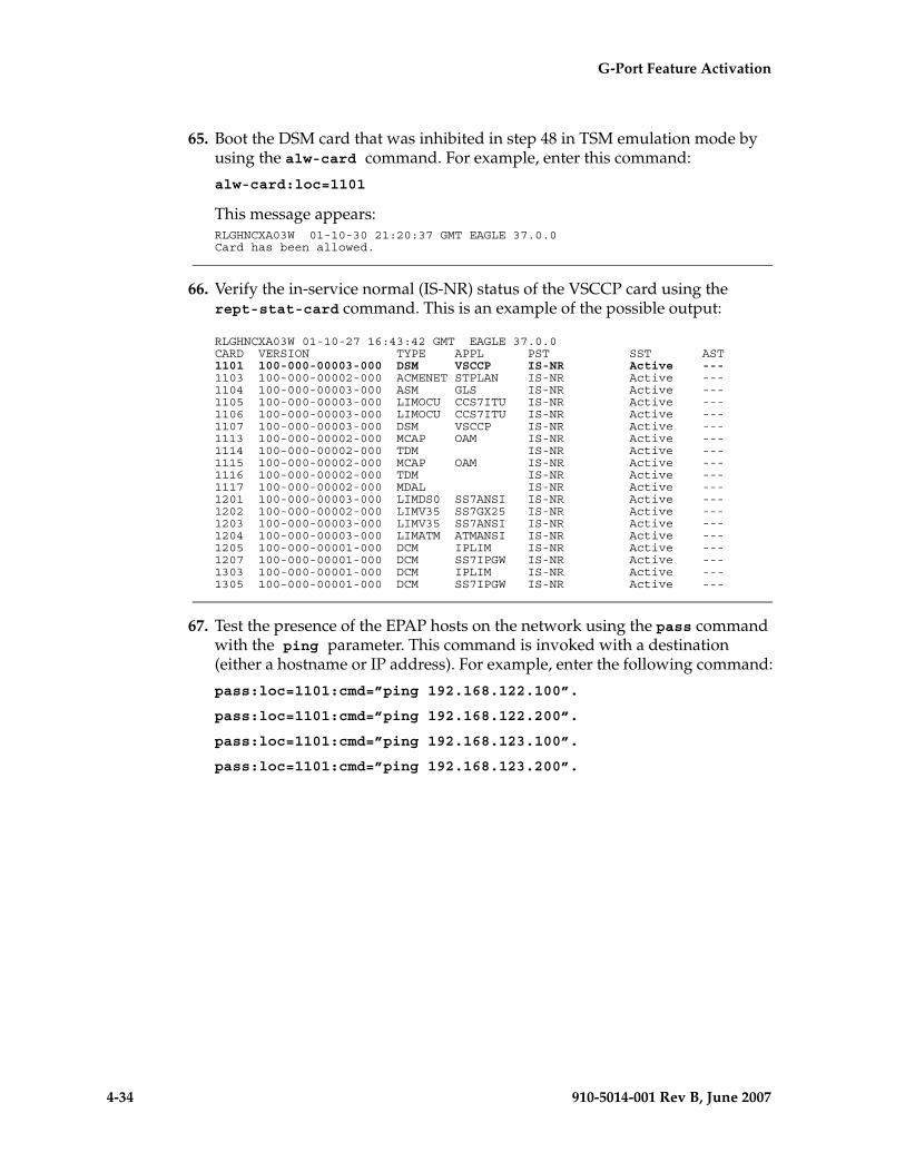
4-34 910-5014-001 Rev B, June 2007
- Draft - G-Port Feature Activation
65. Boot the DSM card that was inhibited in step 48 in TSM emulation mode by using the alw-card command. For example, enter this command:
alw-card:loc=1101
This message appears:RLGHNCXA03W 01-10-30 21:20:37 GMT EAGLE 37.0.0Card has been allowed.
66. Verify the in-service normal (IS-NR) status of the VSCCP card using the rept-stat-card command. This is an example of the possible output:
RLGHNCXA03W 01-10-27 16:43:42 GMT EAGLE 37.0.0CARD VERSION TYPE APPL PST SST AST1101 100-000-00003-000 DSM VSCCP IS-NR Active ---1103 100-000-00002-000 ACMENET STPLAN IS-NR Active ---1104 100-000-00003-000 ASM GLS IS-NR Active ---1105 100-000-00003-000 LIMOCU CCS7ITU IS-NR Active ---1106 100-000-00003-000 LIMOCU CCS7ITU IS-NR Active ---1107 100-000-00003-000 DSM VSCCP IS-NR Active ---1113 100-000-00002-000 MCAP OAM IS-NR Active ---1114 100-000-00002-000 TDM IS-NR Active ---1115 100-000-00002-000 MCAP OAM IS-NR Active ---1116 100-000-00002-000 TDM IS-NR Active ---1117 100-000-00002-000 MDAL IS-NR Active ---1201 100-000-00003-000 LIMDS0 SS7ANSI IS-NR Active ---1202 100-000-00002-000 LIMV35 SS7GX25 IS-NR Active ---1203 100-000-00003-000 LIMV35 SS7ANSI IS-NR Active ---1204 100-000-00003-000 LIMATM ATMANSI IS-NR Active ---1205 100-000-00001-000 DCM IPLIM IS-NR Active ---1207 100-000-00001-000 DCM SS7IPGW IS-NR Active ---1303 100-000-00001-000 DCM IPLIM IS-NR Active ---1305 100-000-00001-000 DCM SS7IPGW IS-NR Active ---
67. Test the presence of the EPAP hosts on the network using the pass command with the ping parameter. This command is invoked with a destination (either a hostname or IP address). For example, enter the following command:
pass:loc=1101:cmd=”ping 192.168.122.100”.
pass:loc=1101:cmd=”ping 192.168.122.200”.
pass:loc=1101:cmd=”ping 192.168.123.100”.
pass:loc=1101:cmd=”ping 192.168.123.200”.
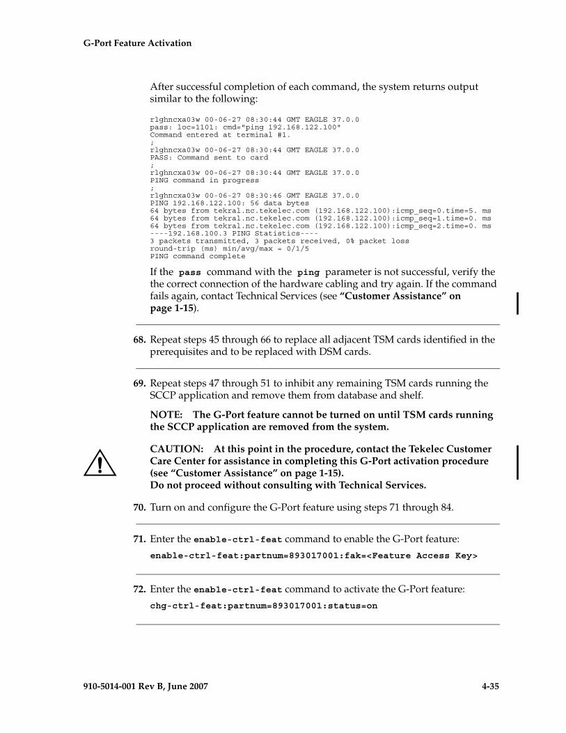
G-Port Feature Activation - Pr- Draft -elim
910-5014-001 Rev B, June 2007 4-35
After successful completion of each command, the system returns output similar to the following:
rlghncxa03w 00-06-27 08:30:44 GMT EAGLE 37.0.0pass: loc=1101: cmd="ping 192.168.122.100"Command entered at terminal #1.;rlghncxa03w 00-06-27 08:30:44 GMT EAGLE 37.0.0PASS: Command sent to card;rlghncxa03w 00-06-27 08:30:44 GMT EAGLE 37.0.0PING command in progress;rlghncxa03w 00-06-27 08:30:46 GMT EAGLE 37.0.0PING 192.168.122.100: 56 data bytes64 bytes from tekral.nc.tekelec.com (192.168.122.100):icmp_seq=0.time=5. ms64 bytes from tekral.nc.tekelec.com (192.168.122.100):icmp_seq=1.time=0. ms64 bytes from tekral.nc.tekelec.com (192.168.122.100):icmp_seq=2.time=0. ms----192.168.100.3 PING Statistics----3 packets transmitted, 3 packets received, 0% packet lossround-trip (ms) min/avg/max = 0/1/5PING command complete
If the pass command with the ping parameter is not successful, verify the the correct connection of the hardware cabling and try again. If the command fails again, contact Technical Services (see “Customer Assistance” on page 1-15).
68. Repeat steps 45 through 66 to replace all adjacent TSM cards identified in the prerequisites and to be replaced with DSM cards.
69. Repeat steps 47 through 51 to inhibit any remaining TSM cards running the SCCP application and remove them from database and shelf.
NOTE: The G-Port feature cannot be turned on until TSM cards running the SCCP application are removed from the system.
CAUTION: At this point in the procedure, contact the Tekelec Customer Care Center for assistance in completing this G-Port activation procedure (see “Customer Assistance” on page 1-15). Do not proceed without consulting with Technical Services.
70. Turn on and configure the G-Port feature using steps 71 through 84.
71. Enter the enable-ctrl-feat command to enable the G-Port feature:
enable-ctrl-feat:partnum=893017001:fak=<Feature Access Key>
72. Enter the enable-ctrl-feat command to activate the G-Port feature:
chg-ctrl-feat:partnum=893017001:status=on
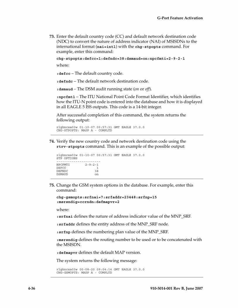
4-36 910-5014-001 Rev B, June 2007
- Draft - G-Port Feature Activation
73. Enter the default country code (CC) and default network destination code (NDC) to convert the nature of address indicator (NAI) of MSISDNs to the international format (nai=intl) with the chg-stpopts command. For example, enter this command:
chg-stpopts:defcc=1:defndc=38:dsmaud=on:npcfmti=2-9-2-1
where:
:defcc – The default country code.
:defndc – The default network destination code.
:dsmaud – The DSM audit running state (on or off).
:npcfmt1 – The ITU National Point Code Format Identifier, which identifies how the ITU-N point code is entered into the database and how it is displayed in all EAGLE 5 ISS outputs. This code is a 14-bit integer.
After successful completion of this command, the system returns the following output:
rlghncxa03w 01-10-07 00:57:31 GMT EAGLE 37.0.0CHG-STPOPTS: MASP A - COMPLTD
74. Verify the new country code and network destination code using the rtrv-stpopts command. This is an example of the possible output:
rlghncxa03w 01-10-07 00:57:31 GMT EAGLE 37.0.0STP OPTIONS -----------------------NPCFMTI 2-9-2-1 DEFCC 1 DEFNDC 38 DSMAUD on
75. Change the GSM system options in the database. For example, enter this command:
chg-gsmopts:srfnai=7:srfaddr=23448:srfnp=15:msrsndig=ccrndn:defmapvr=2
where:
:srfnai defines the nature of address indicator value of the MNP_SRF.
:srfaddr defines the entity address of the MNP_SRF node.
:srfnp defines the numbering plan value of the MNP_SRF.
:msrsndig defines the routing number to be used or to be concatenated with the MSISDN.
:defmapvr defines the default MAP version.
The system returns the following message:
rlghncxa03w 00-08-20 09:04:14 GMT EAGLE 37.0.0CHG-GSMOPTS: MASP A - COMPLTD
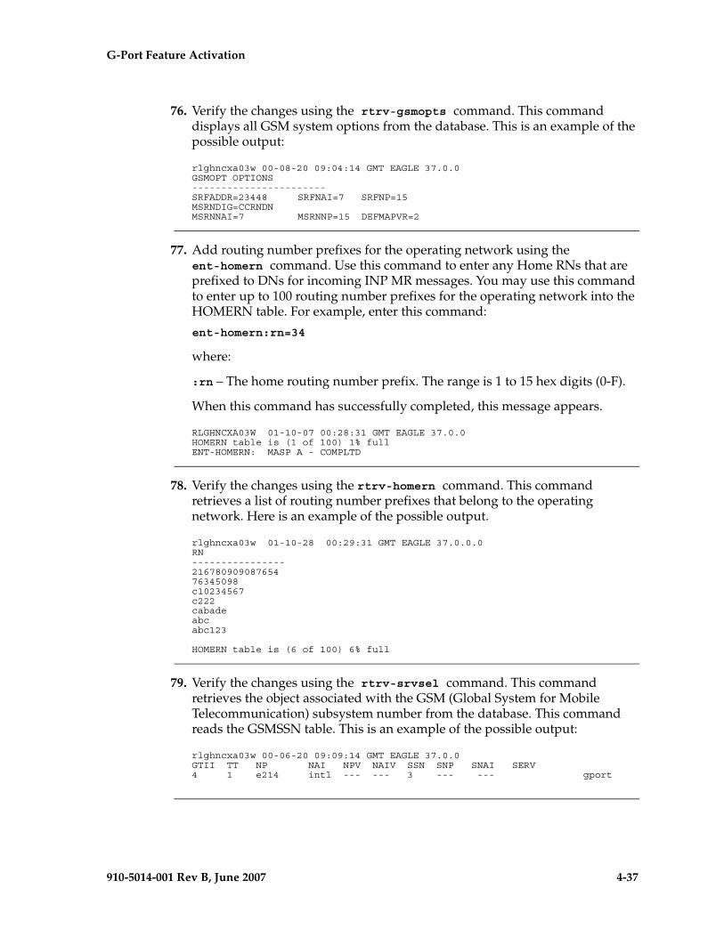
G-Port Feature Activation - Pr- Draft -elim
910-5014-001 Rev B, June 2007 4-37
76. Verify the changes using the rtrv-gsmopts command. This command displays all GSM system options from the database. This is an example of the possible output:
rlghncxa03w 00-08-20 09:04:14 GMT EAGLE 37.0.0GSMOPT OPTIONS -----------------------SRFADDR=23448 SRFNAI=7 SRFNP=15MSRNDIG=CCRNDNMSRNNAI=7 MSRNNP=15 DEFMAPVR=2
77. Add routing number prefixes for the operating network using the ent-homern command. Use this command to enter any Home RNs that are prefixed to DNs for incoming INP MR messages. You may use this command to enter up to 100 routing number prefixes for the operating network into the HOMERN table. For example, enter this command:
ent-homern:rn=34
where:
:rn – The home routing number prefix. The range is 1 to 15 hex digits (0-F).
When this command has successfully completed, this message appears.
RLGHNCXA03W 01-10-07 00:28:31 GMT EAGLE 37.0.0 HOMERN table is (1 of 100) 1% full ENT-HOMERN: MASP A - COMPLTD
78. Verify the changes using the rtrv-homern command. This command retrieves a list of routing number prefixes that belong to the operating network. Here is an example of the possible output.
rlghncxa03w 01-10-28 00:29:31 GMT EAGLE 37.0.0.0RN ---------------- 21678090908765476345098c10234567c222cabadeabcabc123
HOMERN table is (6 of 100) 6% full
79. Verify the changes using the rtrv-srvsel command. This command retrieves the object associated with the GSM (Global System for Mobile Telecommunication) subsystem number from the database. This command reads the GSMSSN table. This is an example of the possible output:
rlghncxa03w 00-06-20 09:09:14 GMT EAGLE 37.0.0GTII TT NP NAI NPV NAIV SSN SNP SNAI SERV4 1 e214 intl --- --- 3 --- --- gport
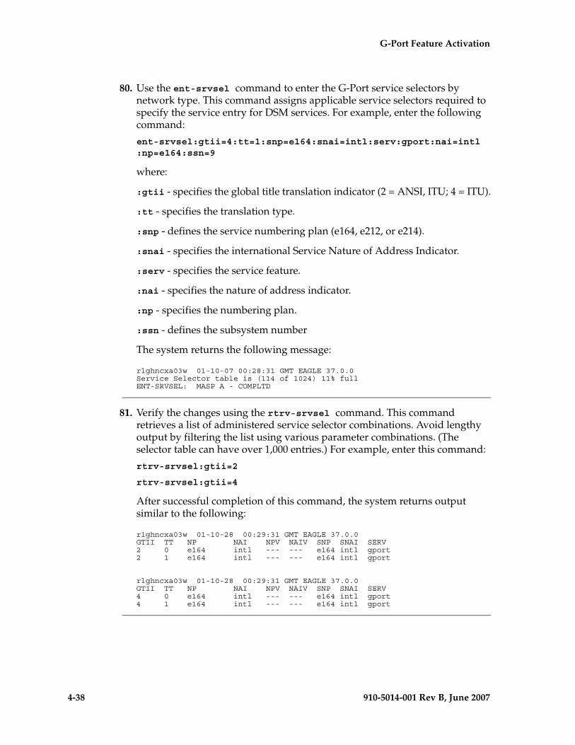
4-38 910-5014-001 Rev B, June 2007
- Draft - G-Port Feature Activation
80. Use the ent-srvsel command to enter the G-Port service selectors by network type. This command assigns applicable service selectors required to specify the service entry for DSM services. For example, enter the following command:
ent-srvsel:gtii=4:tt=1:snp=e164:snai=intl:serv:gport:nai=intl:np=e164:ssn=9
where:
:gtii - specifies the global title translation indicator (2 = ANSI, ITU; 4 = ITU).
:tt - specifies the translation type.
:snp - defines the service numbering plan (e164, e212, or e214).
:snai - specifies the international Service Nature of Address Indicator.
:serv - specifies the service feature.
:nai - specifies the nature of address indicator.
:np - specifies the numbering plan.
:ssn - defines the subsystem number
The system returns the following message:
rlghncxa03w 01-10-07 00:28:31 GMT EAGLE 37.0.0Service Selector table is (114 of 1024) 11% full ENT-SRVSEL: MASP A - COMPLTD
81. Verify the changes using the rtrv-srvsel command. This command retrieves a list of administered service selector combinations. Avoid lengthy output by filtering the list using various parameter combinations. (The selector table can have over 1,000 entries.) For example, enter this command:
rtrv-srvsel:gtii=2
rtrv-srvsel:gtii=4
After successful completion of this command, the system returns output similar to the following:
rlghncxa03w 01-10-28 00:29:31 GMT EAGLE 37.0.0GTII TT NP NAI NPV NAIV SNP SNAI SERV 2 0 e164 intl --- --- e164 intl gport 2 1 e164 intl --- --- e164 intl gport
rlghncxa03w 01-10-28 00:29:31 GMT EAGLE 37.0.0GTII TT NP NAI NPV NAIV SNP SNAI SERV 4 0 e164 intl --- --- e164 intl gport 4 1 e164 intl --- --- e164 intl gport
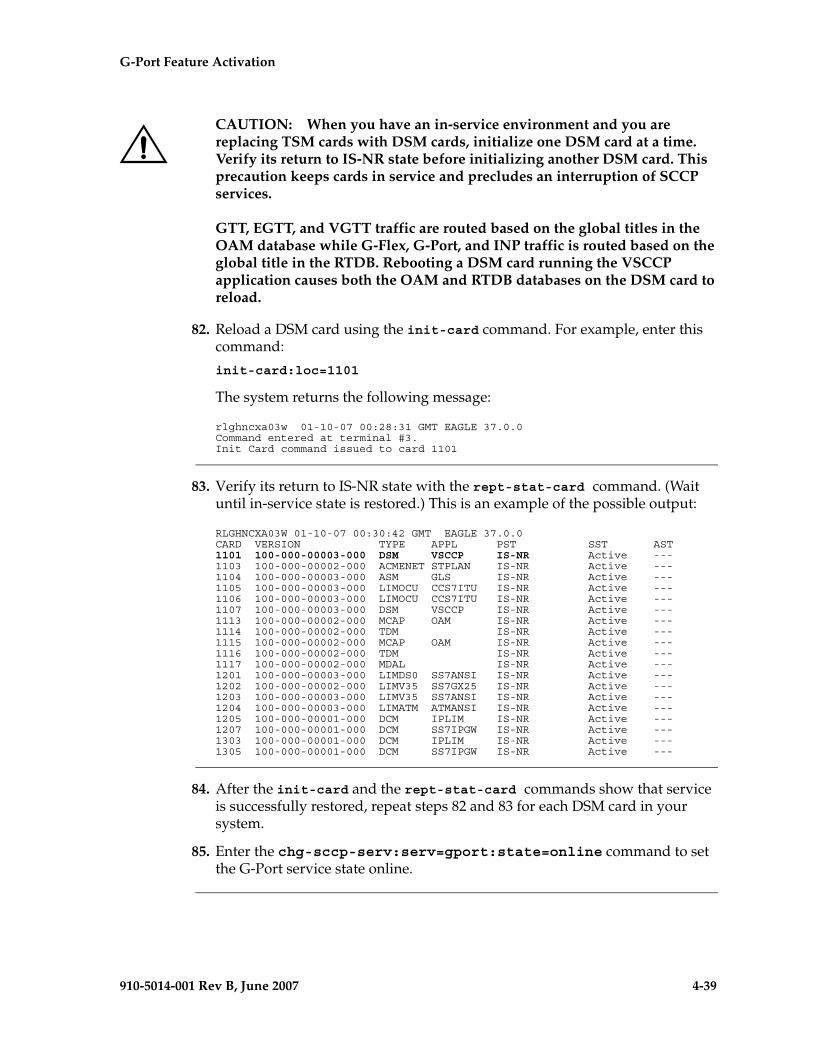
G-Port Feature Activation - Pr- Draft -elim
910-5014-001 Rev B, June 2007 4-39
CAUTION: When you have an in-service environment and you are replacing TSM cards with DSM cards, initialize one DSM card at a time. Verify its return to IS-NR state before initializing another DSM card. This precaution keeps cards in service and precludes an interruption of SCCP services.
GTT, EGTT, and VGTT traffic are routed based on the global titles in the OAM database while G-Flex, G-Port, and INP traffic is routed based on the global title in the RTDB. Rebooting a DSM card running the VSCCP application causes both the OAM and RTDB databases on the DSM card to reload.
82. Reload a DSM card using the init-card command. For example, enter this command:
init-card:loc=1101
The system returns the following message:
rlghncxa03w 01-10-07 00:28:31 GMT EAGLE 37.0.0Command entered at terminal #3. Init Card command issued to card 1101
83. Verify its return to IS-NR state with the rept-stat-card command. (Wait until in-service state is restored.) This is an example of the possible output:
RLGHNCXA03W 01-10-07 00:30:42 GMT EAGLE 37.0.0CARD VERSION TYPE APPL PST SST AST1101 100-000-00003-000 DSM VSCCP IS-NR Active ---1103 100-000-00002-000 ACMENET STPLAN IS-NR Active ---1104 100-000-00003-000 ASM GLS IS-NR Active ---1105 100-000-00003-000 LIMOCU CCS7ITU IS-NR Active ---1106 100-000-00003-000 LIMOCU CCS7ITU IS-NR Active ---1107 100-000-00003-000 DSM VSCCP IS-NR Active ---1113 100-000-00002-000 MCAP OAM IS-NR Active ---1114 100-000-00002-000 TDM IS-NR Active ---1115 100-000-00002-000 MCAP OAM IS-NR Active ---1116 100-000-00002-000 TDM IS-NR Active ---1117 100-000-00002-000 MDAL IS-NR Active ---1201 100-000-00003-000 LIMDS0 SS7ANSI IS-NR Active ---1202 100-000-00002-000 LIMV35 SS7GX25 IS-NR Active ---1203 100-000-00003-000 LIMV35 SS7ANSI IS-NR Active ---1204 100-000-00003-000 LIMATM ATMANSI IS-NR Active ---1205 100-000-00001-000 DCM IPLIM IS-NR Active ---1207 100-000-00001-000 DCM SS7IPGW IS-NR Active ---1303 100-000-00001-000 DCM IPLIM IS-NR Active ---1305 100-000-00001-000 DCM SS7IPGW IS-NR Active ---
84. After the init-card and the rept-stat-card commands show that service is successfully restored, repeat steps 82 and 83 for each DSM card in your system.
85. Enter the chg-sccp-serv:serv=gport:state=online command to set the G-Port service state online.
4-40 910-5014-001 Rev B, June 2007
- Draft - G-Port Feature Activation
86. Confirm that essential activation procedures are successful.
• Use rept-stat-sccp to verify all your DSM cards are loaded and are IS-NR (in-service normal) status.
• Use rept-stat-mps to verify all your DSM cards and the EPAP are connected and operational.
• Use rept-stat-db:display=all to verify database levels are identical for the EPAP PDB and RTDB and the RTDBs on the DSM cards.
The G-Port feature is now installed, activated, and ready for operations.
PPSMS Provisioning and Activation
The following gives the general sequence of the provisioning required to support PPSMS on the EAGLE 5 ISS. This procedure assumes G-Port and GTT are provisioned and activated.
Procedure
1. Use the following command to enter the NT serial number.
ent-serial-num:serial=<System NT serial number>:lock=yes
Enter NT serial number into EAGLE 5 ISS database. If the NT serial number is already entered, then ignore this step.
2. Enter the enable-ctrl-feat command to enable the PPSMS feature.
enable-ctrl-feat:partnum=893006701:fak=<Feature Access Key>
3. Enter the chg-ctrl-feat command to activate the PPSMS feature.
chg-ctrl-feat:partnum=893006701:status=on
4. Enter the ent-srvsel command to enter GSM G-Port Global Title Selectors These selectors trigger G-Port as well as PPSMS processing.
ent-srvsel:gtii=4:tt=0:np=e164:nai=intl:serv=smsmr
This example sets up the service selectors needed to select incoming messages with GTI=4, NP=E164, TT=0 and NAI=INTL selected for G-Port/PPSMS service.
G-Port Feature Activation - Pr- Draft -elim
910-5014-001 Rev B, June 2007 4-41
5. Use the chg-gsmopts command to enter various GSM system options, including PPSMS options.
chg-gsmopts:ppsmspci1=1-1-1:ppsmsri1=gt:ppsmspci2=2-2-2: ppsmsri2=gt
This example enters PC and RI for two PPSMS nodes.
6. Use the chg-gsmopts command to enter various PPSMS options.
chg-gsmopts:ppsmsgta=123543235
This command defines one PPSMS global title for filtering.
7. Use the chg-gsmopts command to enter various PPSMS options.
chg-gsmopts: ppsmsgta=555648309
This command defines a second PPSMS global title for filtering.
8. Use the ent-map command to enter mated applications for use with SCCP network management and routing to mated nodes when outgoing RI = route-on-SSN.
ent-map: pci=1-1-1:ssn=8:rc=10:mpci=3-3-3:mssn=8:materc=10:grp=smsc
Enters PPSMS PC 1-1-1 and node PC 3-3-3 as load shared mates. This entry is only used if the PPSMS RI is equal to the SSN in the GSMOPTS table. This is not the case for PPSMS PC1 in this example.
9. Use the ent-mrn command to enter mated relay nodes for routing to mated node when outgoing RI=route-on-GT.
ent-mrn:pci=2-2-2:rc=10:pci1=3-3-3:rc1=10
Enters PPSMS PC 2-2-2 and node PC 3-3-3 as load shared mates. This entry is only used if the PPSMS RI is equal to the GT in the GSMOPTS table, which it is in this case for PPSMSPC2.
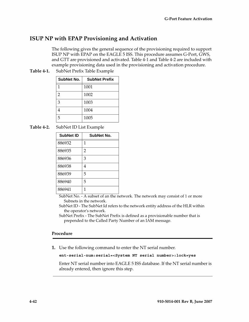
4-42 910-5014-001 Rev B, June 2007
- Draft - G-Port Feature Activation
ISUP NP with EPAP Provisioning and Activation
The following gives the general sequence of the provisioning required to support ISUP NP with EPAP on the EAGLE 5 ISS. This procedure assumes G-Port, GWS, and GTT are provisioned and activated. Table 4-1 and Table 4-2 are included with example provisioning data used in the provisioning and activation procedure.
Table 4-1. SubNet Prefix Table Example
Table 4-2. SubNet ID List Example
SubNet No. - A subset of an the network. The network may consist of 1 or more Subnets in the network.
SubNet ID - The SubNet Id refers to the network entity address of the HLR within the operator's network.
SubNet Prefix - The SubNet Prefix is defined as a provisionable number that is prepended to the Called Party Number of an IAM message.
Procedure
1. Use the following command to enter the NT serial number.
ent-serial-num:serial=<System NT serial number>:lock=yes
Enter NT serial number into EAGLE 5 ISS database. If the NT serial number is already entered, then ignore this step.
SubNet No. SubNet Prefix
1 1001
2 1002
3 1003
4 1004
5 1005
SubNet ID SubNet No.
886932 1
886935 2
886936 3
886938 4
886939 5
886940 5
886941 1
G-Port Feature Activation - Pr- Draft -elim
910-5014-001 Rev B, June 2007 4-43
2. Enter the enable-ctrl-feat command to enable the ISUP NP with EPAP feature.
enable-ctrl-feat:partnum=893013801:fak=<Feature Access Key>
3. Enter the chg-prefix-feat command to relate the ISUP NP with EPAP feature to a prefix, and to specify an prefix ID number that is used to refer to the prefix value from another table. Examples follow:
chg-prefix:feature="isup np with epap"prefixnum=1:prefix=1001
chg-prefix:feature="isup np with epap"prefixnum=2:prefix=1002
chg-prefix:feature="isup np with epap"prefixnum=3:prefix=1003
chg-prefix:feature="isup np with epap"prefixnum=4:prefix=1004
chg-prefix:feature="isup np with epap"prefixnum=5:prefix=1005
4. Enter the following command to determine the allowed length for the subnetid values.
ent-subnetid:subnetidlen=6
5. Enter the following command to associate the subnetid with a subnet number.
ent-subnetid:subnetid=886932:subnetnum=1
ent-subnetid:subnetid=886935:subnetnum=2
ent-subnetid:subnetid=886936:subnetnum=3
ent-subnetid:subnetid=886938:subnetnum=4
ent-subnetid:subnetid=886940:subnetnum=5
6. The EPAP database must be populated for the ported suscribers. Refer to the Provisioning Database Interface Manual to add and update the Network Entity and Dialed Number data for ported subscribers and subscribers belonging to the subnet.
7. Enter the commands related to Gateway Screening to add the STOP ACTION TLNP for the required combination of the screening rules for the OPC, DPC, SIO, ISUP, and message type=IAM.
For more details about gateway screening commands, refer to the Database Administration Manual—Gateway Screening. The gateway screening commands include the following.
a. Command(s) to configure the gateway screening stop action sets in the system database.
chg-gws-actset:actid=4:actname=fet:act1=tlnp
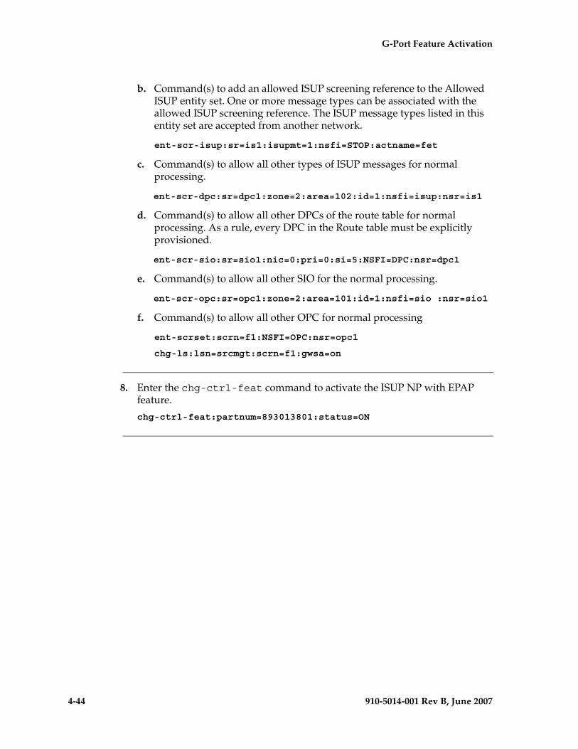
4-44 910-5014-001 Rev B, June 2007
- Draft - G-Port Feature Activation
b. Command(s) to add an allowed ISUP screening reference to the Allowed ISUP entity set. One or more message types can be associated with the allowed ISUP screening reference. The ISUP message types listed in this entity set are accepted from another network.
ent-scr-isup:sr=is1:isupmt=1:nsfi=STOP:actname=fet
c. Command(s) to allow all other types of ISUP messages for normal processing.
ent-scr-dpc:sr=dpc1:zone=2:area=102:id=1:nsfi=isup:nsr=is1
d. Command(s) to allow all other DPCs of the route table for normal processing. As a rule, every DPC in the Route table must be explicitly provisioned.
ent-scr-sio:sr=sio1:nic=0:pri=0:si=5:NSFI=DPC:nsr=dpc1
e. Command(s) to allow all other SIO for the normal processing.
ent-scr-opc:sr=opc1:zone=2:area=101:id=1:nsfi=sio :nsr=sio1
f. Command(s) to allow all other OPC for normal processing
ent-scrset:scrn=f1:NSFI=OPC:nsr=opc1
chg-ls:lsn=srcmgt:scrn=f1:gwsa=on
8. Enter the chg-ctrl-feat command to activate the ISUP NP with EPAP feature.
chg-ctrl-feat:partnum=893013801:status=ON
G-Port Feature Activation - Pr- Draft -elim
910-5014-001 Rev B, June 2007 4-45
Activating the 1100 TPS/DSM for ITU NP Feature
This procedure is used to enable and turn on the 1100 TPS/DSM for ITU NP feature. This feature provides up to 26,400 transactions per second when the maximum number of DSM cards are installed in the EAGLE 5 ISS and one or more EPAP-related features (such as G-Port, G-Flex, A-Port, INP, EIR, Migration) are enabled and turned on.
This feature can be enabled only for DSMs that are rated at 850 transactions per second (TPS).
CAUTION: The increase of the DSM capacity, 1100 TPS per DSM, assumes incoming traffic consists of at least 30% of GTT routed traffic that does not require EPAP based lookup. If more than 70% of incoming traffic requires EPAP based lookup, Group Ticket Voucher (TVG) may shutdown and overall TVG capacity of 1100 for the card may not be met.
The feature access key is based on the feature’s part number and the serial number of the EAGLE 5 ISS, making the feature access key site-specific.
The enable-ctrl-feat command enables the 1100 TPS/DSM for ITU NP feature by inputting the feature’s access key and the feature’s part number with these parameters:
:fak – The feature access key provided by Tekelec. The feature access key contains 13 alphanumeric characters and is not case sensitive.
:partnum – The Tekelec-issued part number of the 1100 TPS/DSM for ITU NP feature, 893018001.
This feature cannot be enabled with a temporary feature access key.
The 1100 TPS/DSM for ITU NP feature cannot be enabled if:
• The LNP feature is enabled.
The status of the LNP feature is shown with the rtrv-ctrl-feat command output.
• The ANSI G-Flex STP Option is enabled.
The status of the ANSI G-Flex STP Option is shown in the rtrv-stpopts command output.
• The GTT feature is not turned on.
The status of the GTT feature is shown in the rtrv-feat command output.
The 1100 TPS/DSM for ITU NP feature cannot be enabled unless the EAGLE 5 ISS contains DSM cards.
4-46 910-5014-001 Rev B, June 2007
- Draft - G-Port Feature Activation
The enable-ctrl-feat command requires that the database contain a valid serial number for the EAGLE 5 ISS, and that this serial number is locked. This can be verified with the rtrv-serial-num command. The EAGLE 5 ISS is shipped with a serial number in the database, but the serial number is not locked. The serial number can be changed, if necessary, and locked once the EAGLE 5 ISS is on-site, with the ent-serial-num command. The ent-serial-num command uses these parameters.
:serial – The serial number assigned to the EAGLE 5 ISS. The serial number is not case sensitive.
:lock – Specifies whether or not the serial number is locked. This parameter has only one value, yes, which locks the serial number. Once the serial number is locked, it cannot be changed.
NOTE: To enter and lock the EAGLE 5 ISS’s serial number, the ent-serial-num command must be entered twice, once to add the correct serial number to the database with the serial parameter, then again with the serial and the lock=yes parameters to lock the serial number. You should verify that the serial number in the database is correct before locking the serial number. The serial number can be found on a label affixed to the control shelf (shelf 1100).
Once the 1100 TPS/DSM for ITU NP feature has been enabled, the feature must be turned on with the chg-ctrl-feat command. The chg-ctrl-feat command uses these parameters:
:partnum – The Tekelec-issued part number of the 1100 TPS/DSM for ITU NP feature, 893019101.
:status=on – used to turn the 1100 TPS/DSM for ITU NP feature on.
This feature increases the processing capacity of SCCP traffic for an EAGLE 5 ISS processing EPAP-based traffic to 26,400 transactions per second. To achieve this increase in SCCP processing capacity, a maximum of 25 DSM cards must be provisioned and installed in the EAGLE 5 ISS.
Procedure
1. Display the status of the 1100 TPS/DSM for ITU NP feature by entering the rtrv-ctrl-feat command. The 1100 TPS/DSM for ITU NP feature is enabled. The following is an example of the possible output:
rlghncxa03w 07-05-28 21:15:37 GMT EAGLE5 37.0.0
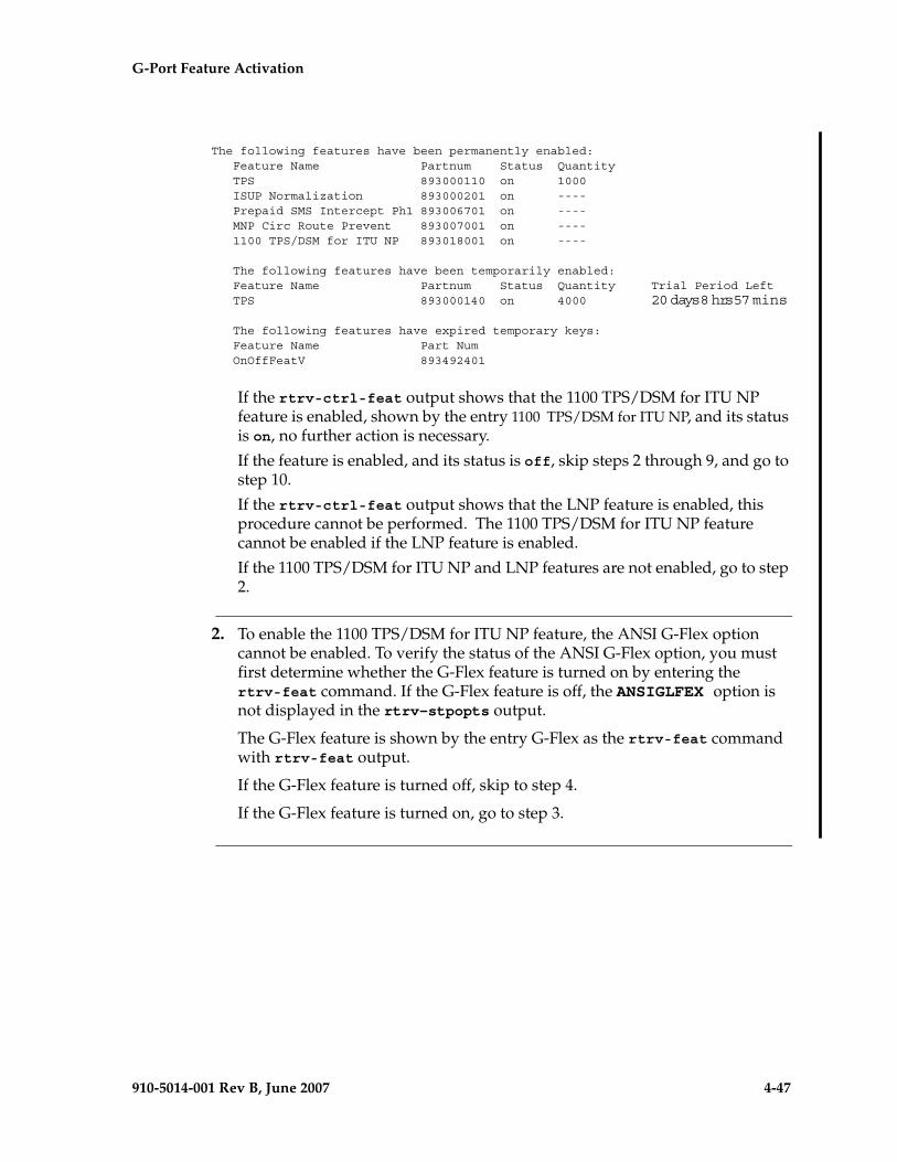
G-Port Feature Activation - Pr- Draft -elim
910-5014-001 Rev B, June 2007 4-47
The following features have been permanently enabled: Feature Name Partnum Status Quantity TPS 893000110 on 1000 ISUP Normalization 893000201 on ---- Prepaid SMS Intercept Ph1 893006701 on ---- MNP Circ Route Prevent 893007001 on ---- 1100 TPS/DSM for ITU NP 893018001 on ----
The following features have been temporarily enabled: Feature Name Partnum Status Quantity Trial Period Left TPS 893000140 on 4000 20 days 8 hrs 57 mins
The following features have expired temporary keys: Feature Name Part Num OnOffFeatV 893492401
If the rtrv-ctrl-feat output shows that the 1100 TPS/DSM for ITU NP feature is enabled, shown by the entry 1100 TPS/DSM for ITU NP, and its status is on, no further action is necessary.
If the feature is enabled, and its status is off, skip steps 2 through 9, and go to step 10.
If the rtrv-ctrl-feat output shows that the LNP feature is enabled, this procedure cannot be performed. The 1100 TPS/DSM for ITU NP feature cannot be enabled if the LNP feature is enabled.
If the 1100 TPS/DSM for ITU NP and LNP features are not enabled, go to step 2.
2. To enable the 1100 TPS/DSM for ITU NP feature, the ANSI G-Flex option cannot be enabled. To verify the status of the ANSI G-Flex option, you must first determine whether the G-Flex feature is turned on by entering the rtrv-feat command. If the G-Flex feature is off, the ANSIGLFEX option is not displayed in the rtrv-stpopts output.
The G-Flex feature is shown by the entry G-Flex as the rtrv-feat command with rtrv-feat output.
If the G-Flex feature is turned off, skip to step 4.
If the G-Flex feature is turned on, go to step 3.
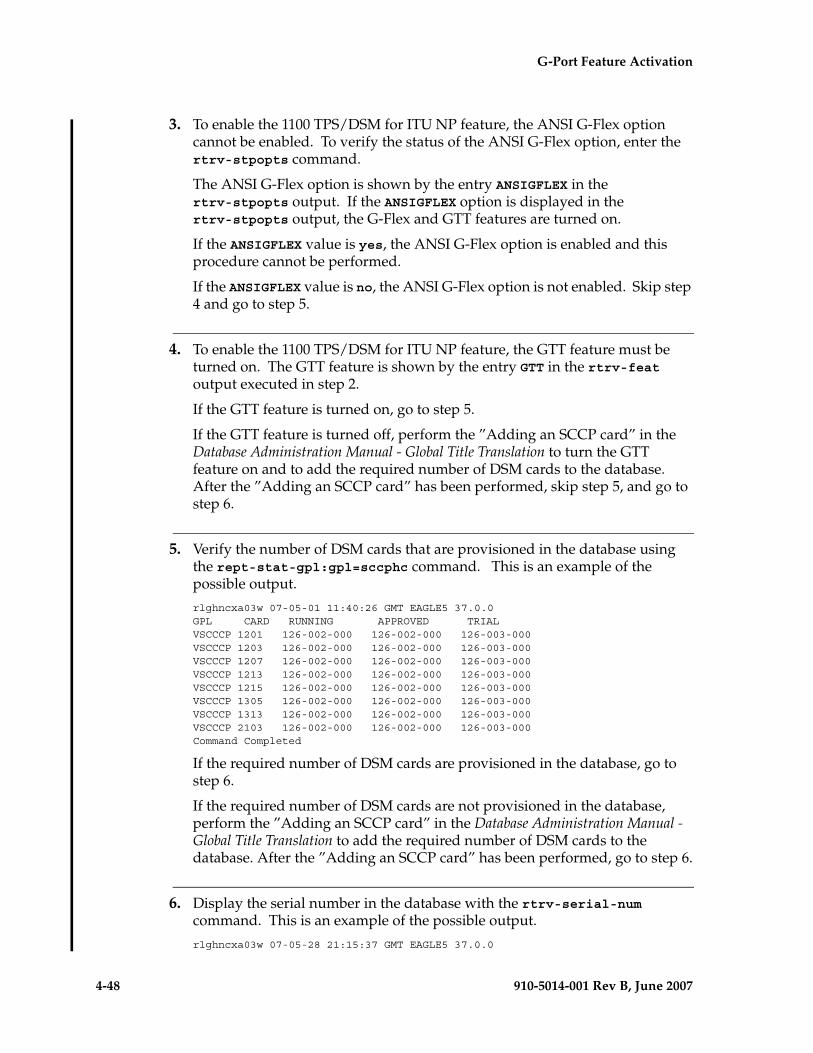
4-48 910-5014-001 Rev B, June 2007
- Draft - G-Port Feature Activation
3. To enable the 1100 TPS/DSM for ITU NP feature, the ANSI G-Flex option cannot be enabled. To verify the status of the ANSI G-Flex option, enter the rtrv-stpopts command.
The ANSI G-Flex option is shown by the entry ANSIGFLEX in the rtrv-stpopts output. If the ANSIGFLEX option is displayed in the rtrv-stpopts output, the G-Flex and GTT features are turned on.
If the ANSIGFLEX value is yes, the ANSI G-Flex option is enabled and this procedure cannot be performed.
If the ANSIGFLEX value is no, the ANSI G-Flex option is not enabled. Skip step 4 and go to step 5.
4. To enable the 1100 TPS/DSM for ITU NP feature, the GTT feature must be turned on. The GTT feature is shown by the entry GTT in the rtrv-feat output executed in step 2.
If the GTT feature is turned on, go to step 5.
If the GTT feature is turned off, perform the ”Adding an SCCP card” in the Database Administration Manual - Global Title Translation to turn the GTT feature on and to add the required number of DSM cards to the database. After the ”Adding an SCCP card” has been performed, skip step 5, and go to step 6.
5. Verify the number of DSM cards that are provisioned in the database using the rept-stat-gpl:gpl=sccphc command. This is an example of the possible output.
rlghncxa03w 07-05-01 11:40:26 GMT EAGLE5 37.0.0GPL CARD RUNNING APPROVED TRIALVSCCCP 1201 126-002-000 126-002-000 126-003-000VSCCCP 1203 126-002-000 126-002-000 126-003-000VSCCCP 1207 126-002-000 126-002-000 126-003-000VSCCCP 1213 126-002-000 126-002-000 126-003-000VSCCCP 1215 126-002-000 126-002-000 126-003-000VSCCCP 1305 126-002-000 126-002-000 126-003-000VSCCCP 1313 126-002-000 126-002-000 126-003-000VSCCCP 2103 126-002-000 126-002-000 126-003-000Command Completed
If the required number of DSM cards are provisioned in the database, go to step 6.
If the required number of DSM cards are not provisioned in the database, perform the ”Adding an SCCP card” in the Database Administration Manual - Global Title Translation to add the required number of DSM cards to the database. After the ”Adding an SCCP card” has been performed, go to step 6.
6. Display the serial number in the database with the rtrv-serial-num command. This is an example of the possible output.
rlghncxa03w 07-05-28 21:15:37 GMT EAGLE5 37.0.0
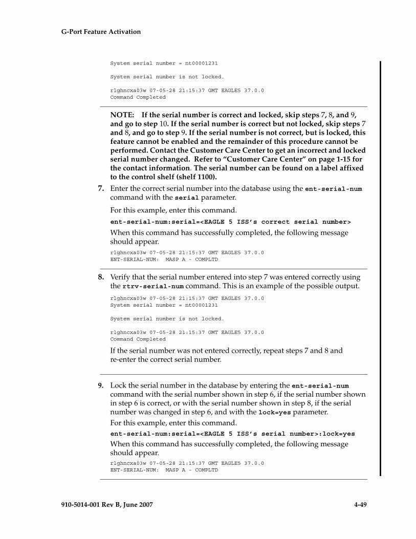
G-Port Feature Activation - Pr- Draft -elim
910-5014-001 Rev B, June 2007 4-49
System serial number = nt00001231
System serial number is not locked.
rlghncxa03w 07-05-28 21:15:37 GMT EAGLE5 37.0.0Command Completed
NOTE: If the serial number is correct and locked, skip steps 7, 8, and 9, and go to step 10. If the serial number is correct but not locked, skip steps 7 and 8, and go to step 9. If the serial number is not correct, but is locked, this feature cannot be enabled and the remainder of this procedure cannot be performed. Contact the Customer Care Center to get an incorrect and locked serial number changed. Refer to “Customer Care Center” on page 1-15 for the contact information. The serial number can be found on a label affixed to the control shelf (shelf 1100).
7. Enter the correct serial number into the database using the ent-serial-num command with the serial parameter.
For this example, enter this command.ent-serial-num:serial=<EAGLE 5 ISS’s correct serial number>
When this command has successfully completed, the following message should appear.rlghncxa03w 07-05-28 21:15:37 GMT EAGLE5 37.0.0ENT-SERIAL-NUM: MASP A - COMPLTD
8. Verify that the serial number entered into step 7 was entered correctly using the rtrv-serial-num command. This is an example of the possible output.
rlghncxa03w 07-05-28 21:15:37 GMT EAGLE5 37.0.0System serial number = nt00001231
System serial number is not locked.
rlghncxa03w 07-05-28 21:15:37 GMT EAGLE5 37.0.0Command Completed
If the serial number was not entered correctly, repeat steps 7 and 8 and re-enter the correct serial number.
9. Lock the serial number in the database by entering the ent-serial-num command with the serial number shown in step 6, if the serial number shown in step 6 is correct, or with the serial number shown in step 8, if the serial number was changed in step 6, and with the lock=yes parameter.For this example, enter this command.ent-serial-num:serial=<EAGLE 5 ISS’s serial number>:lock=yes
When this command has successfully completed, the following message should appear.rlghncxa03w 07-05-28 21:15:37 GMT EAGLE5 37.0.0ENT-SERIAL-NUM: MASP A - COMPLTD
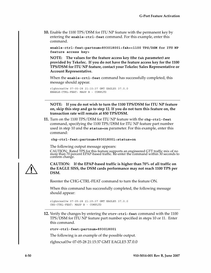
4-50 910-5014-001 Rev B, June 2007
- Draft - G-Port Feature Activation
10. Enable the 1100 TPS/DSM for ITU NP feature with the permanent key by entering the enable-ctrl-feat command. For this example, enter this command.
enable-ctrl-feat:partnum=893018001:fak=<1100 TPS/DSM for ITU NP feature access key>
NOTE: The values for the feature access key (the fak parameter) are provided by Tekelec. If you do not have the feature access key for the 1100 TPS/DSM for ITU NP feature, contact your Tekelec Sales Representative or Account Representative.
When the enable-crtl-feat command has successfully completed, this message should appear.
rlghncxa03w 07-05-28 21:15:37 GMT EAGLE5 37.0.0ENABLE-CTRL-FEAT: MASP B - COMPLTD
NOTE: If you do not wish to turn the 1100 TPS/DSM for ITU NP feature on, skip this step and go to step 12. If you do not turn this feature on, the transaction rate will remain at 850 TPS/DSM.
11. Turn on the 1100 TPS/DSM for ITU NP feature with the chg-ctrl-feat command, specifying the 1100 TPS/DSM for ITU NP feature part number used in step 10 and the status=on parameter. For this example, enter this command:
chg-ctrl-feat:partnum=893018001:status=on
The following output message appears:CAUTION: Rated TPS for this feature supports an engineered GTT traffic mix of no more than 70 percent EPAP-based traffic. Re-enter the command within 30 seconds to confirm change.
CAUTION: If the EPAP-based traffic is higher than 70% of all traffic on the EAGLE 5ISS, the DSM cards performance may not reach 1100 TPS per DSM.
Reenter the CHG-CTRL-FEAT command to turn the feature ON.
When this command has successfully completed, the following message should appear:
rlghncxa03w 07-05-28 21:15:37 GMT EAGLE5 37.0.0CHG-CTRL-FEAT: MASP B - COMPLTD
12. Verify the changes by entering the rtrv-ctrl-feat command with the 1100 TPS/DSM for ITU NP feature part number specified in steps 10 or 11. Enter this command.
rtrv-ctrl-feat:partnum=893018001
The following is an example of the possible output.
rlghncxa03w 07-05-28 21:15:37 GMT EAGLE5 37.0.0
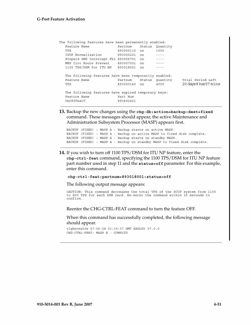
G-Port Feature Activation - Pr- Draft -elim
910-5014-001 Rev B, June 2007 4-51
The following features have been permanently enabled: Feature Name Partnum Status Quantity TPS 893000110 on 1000 ISUP Normalization 893000201 on ---- Prepaid SMS Intercept Ph1 893006701 on ---- MNP Circ Route Prevent 893007001 on ---- 1100 TPS/DSM for ITU NP 893018001 on ----
The following features have been temporarily enabled: Feature Name Partnum Status Quantity Trial Period Left TPS 893000140 on 4000 20 days 8 hrs 57 mins
The following features have expired temporary keys: Feature Name Part Num OnOffFeatV 893492401
13. Backup the new changes using the chg-db:action=backup:dest=fixed command. These messages should appear, the active Maintenance and Administration Subsystem Processor (MASP) appears first.
BACKUP (FIXED) : MASP A - Backup starts on active MASP.BACKUP (FIXED) : MASP A - Backup on active MASP to fixed disk complete.BACKUP (FIXED) : MASP A - Backup starts on standby MASP.BACKUP (FIXED) : MASP A - Backup on standby MASP to fixed disk complete.
14. If you wish to turn off 1100 TPS/DSM for ITU NP feature, enter the chg-ctrl-feat command, specifying the 1100 TPS/DSM for ITU NP feature part number used in step 11 and the status=off parameter. For this example, enter this command.
chg-ctrl-feat:partnum=893018001:status=off
The following output message appears:
CAUTION: This command decreases the total TPS of the SCCP system from 1100 to 850 TPS for each DSM card. Re-enter the command within 30 seconds to confirm.
Reenter the CHG-CTRL-FEAT command to turn the feature OFF.
When this command has successfully completed, the following message should appear.rlghncxa03w 07-05-28 21:15:37 GMT EAGLE5 37.0.0CHG-CTRL-FEAT: MASP B - COMPLTD
4-52 910-5014-001 Rev B, June 2007
- Draft - G-Port Feature Activation
Activating the E5-SM4G Throughput Capacity Feature
This procedure is used to enable and turn on the E5-SM4G Throughput Capacity feature.This feature provides up to 75,000 transactions per second when the maximum nuber of E5-SM4G cards are installed in the EAGLE 5 ISS and one or more EPAP-related features (such as G-Port) are enabled and turned on.
The feature access key is based on the feature’s part number and the serial number of the EAGLE 5 ISS, making the feature access key site-specific.
The enable-ctrl-feat command enables the E5-SM4G Throughput Capacity feature by inputting the feature’s access key and the feature’s part number with these parameters:
:fak – The feature access key provided by Tekelec. The feature access key contains 13 alphanumeric characters and is not case sensitive.
:partnum – The Tekelec-issued part number of the E5-SM4G Throughput Capacity feature, 893019101.
This feature cannot be enabled with a temporary feature access key.
The E5-SM4G Throughput Capacity feature cannot be enabled if:
• The LNP feature is enabled.
• The ANSI G-Flex STP Option is enabled.
• The Eagle 5 Integrated Monitoring Support (E5IS) feature is turned on.
• The STPLAN feature is turned on.
• The GTT feature is not turned on.
The E5-SM4G Throughput Capacity feature cannot be enabled unless the EAGLE 5 ISS contains E5-SM4G cards, and E5-SM4G cards cannot be installed in the EAGLE 5 ISS unless HIPR cards are installed in all shelves. Enter the rept-stat-gpl:gpl=hipr command to verify if HIPR cards are installed in all shelves.
The status of the LNP feature is shown with the rtrv-ctrl-feat command output.
The status of the GTT, E5IS, and STPLAN features is shown in the rtrv-feat command output.
The status of the ANSI G-Flex STP Option is shown in the rtrv-stpopts command output.
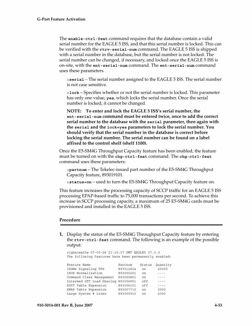
G-Port Feature Activation - Pr- Draft -elim
910-5014-001 Rev B, June 2007 4-53
The enable-ctrl-feat command requires that the database contain a valid serial number for the EAGLE 5 ISS, and that this serial number is locked. This can be verified with the rtrv-serial-num command. The EAGLE 5 ISS is shipped with a serial number in the database, but the serial number is not locked. The serial number can be changed, if necessary, and locked once the EAGLE 5 ISS is on-site, with the ent-serial-num command. The ent-serial-num command uses these parameters.
:serial – The serial number assigned to the EAGLE 5 ISS. The serial number is not case sensitive.
:lock – Specifies whether or not the serial number is locked. This parameter has only one value, yes, which locks the serial number. Once the serial number is locked, it cannot be changed.
NOTE: To enter and lock the EAGLE 5 ISS’s serial number, the ent-serial-num command must be entered twice, once to add the correct serial number to the database with the serial parameter, then again with the serial and the lock=yes parameters to lock the serial number. You should verify that the serial number in the database is correct before locking the serial number. The serial number can be found on a label affixed to the control shelf (shelf 1100).
Once the E5-SM4G Throughput Capacity feature has been enabled, the feature must be turned on with the chg-ctrl-feat command. The chg-ctrl-feat command uses these parameters:
:partnum – The Tekelec-issued part number of the E5-SM4G Throughput Capacity feature, 893019101.
:status=on – used to turn the E5-SM4G Throughput Capacity feature on.
This feature increases the processing capacity of SCCP traffic for an EAGLE 5 ISS processing EPAP-based traffic to 75,000 transactions per second. To achieve this increase in SCCP processing capacity, a maximum of 25 E5-SM4G cards must be provisioned and installed in the EAGLE 5 ISS.
Procedure
1. Display the status of the E5-SM4G Throughput Capacity feature by entering the rtrv-ctrl-feat command. The following is an example of the possible output:
rlghncxa03w 07-05-28 21:15:37 GMT EAGLE5 37.0.0The following features have been permanently enabled:
Feature Name Partnum Status QuantityIPGWx Signaling TPS 893012814 on 20000ISUP Normalization 893000201 on ----Command Class Management 893005801 on ----Intermed GTT Load Sharing 893006901 off ----XGTT Table Expansion 893006101 off ----XMAP Table Expansion 893007710 on 3000Large System # Links 893005910 on 2000
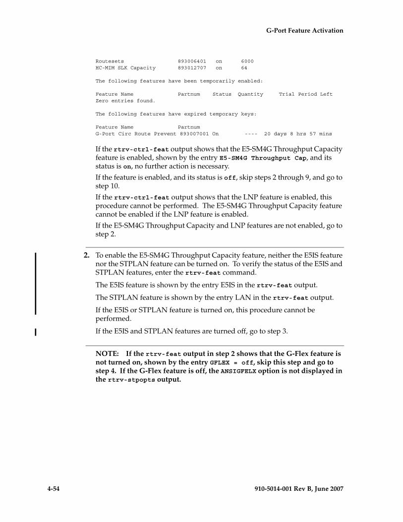
4-54 910-5014-001 Rev B, June 2007
- Draft - G-Port Feature Activation
Routesets 893006401 on 6000HC-MIM SLK Capacity 893012707 on 64
The following features have been temporarily enabled:
Feature Name Partnum Status Quantity Trial Period LeftZero entries found.
The following features have expired temporary keys:
Feature Name PartnumG-Port Circ Route Prevent 893007001 On ---- 20 days 8 hrs 57 mins
If the rtrv-ctrl-feat output shows that the E5-SM4G Throughput Capacity feature is enabled, shown by the entry E5-SM4G Throughput Cap, and its status is on, no further action is necessary.
If the feature is enabled, and its status is off, skip steps 2 through 9, and go to step 10.
If the rtrv-ctrl-feat output shows that the LNP feature is enabled, this procedure cannot be performed. The E5-SM4G Throughput Capacity feature cannot be enabled if the LNP feature is enabled.
If the E5-SM4G Throughput Capacity and LNP features are not enabled, go to step 2.
2. To enable the E5-SM4G Throughput Capacity feature, neither the E5IS feature nor the STPLAN feature can be turned on. To verify the status of the E5IS and STPLAN features, enter the rtrv-feat command.
The E5IS feature is shown by the entry E5IS in the rtrv-feat output.
The STPLAN feature is shown by the entry LAN in the rtrv-feat output.
If the E5IS or STPLAN feature is turned on, this procedure cannot be performed.
If the E5IS and STPLAN features are turned off, go to step 3.
NOTE: If the rtrv-feat output in step 2 shows that the G-Flex feature is not turned on, shown by the entry GFLEX = off, skip this step and go to step 4. If the G-Flex feature is off, the ANSIGFELX option is not displayed in the rtrv-stpopts output.
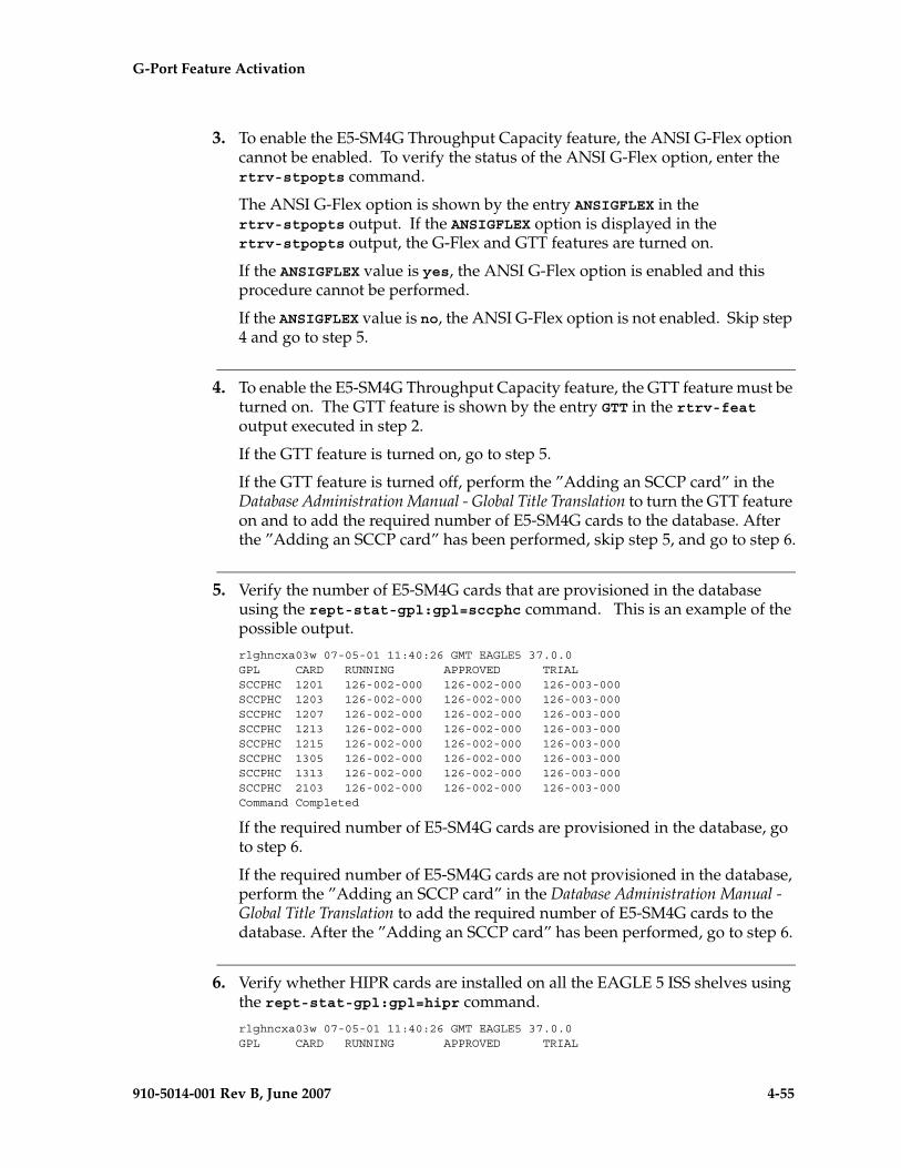
G-Port Feature Activation - Pr- Draft -elim
910-5014-001 Rev B, June 2007 4-55
3. To enable the E5-SM4G Throughput Capacity feature, the ANSI G-Flex option cannot be enabled. To verify the status of the ANSI G-Flex option, enter the rtrv-stpopts command.
The ANSI G-Flex option is shown by the entry ANSIGFLEX in the rtrv-stpopts output. If the ANSIGFLEX option is displayed in the rtrv-stpopts output, the G-Flex and GTT features are turned on.
If the ANSIGFLEX value is yes, the ANSI G-Flex option is enabled and this procedure cannot be performed.
If the ANSIGFLEX value is no, the ANSI G-Flex option is not enabled. Skip step 4 and go to step 5.
4. To enable the E5-SM4G Throughput Capacity feature, the GTT feature must be turned on. The GTT feature is shown by the entry GTT in the rtrv-feat output executed in step 2.
If the GTT feature is turned on, go to step 5.
If the GTT feature is turned off, perform the ”Adding an SCCP card” in the Database Administration Manual - Global Title Translation to turn the GTT feature on and to add the required number of E5-SM4G cards to the database. After the ”Adding an SCCP card” has been performed, skip step 5, and go to step 6.
5. Verify the number of E5-SM4G cards that are provisioned in the database using the rept-stat-gpl:gpl=sccphc command. This is an example of the possible output.
rlghncxa03w 07-05-01 11:40:26 GMT EAGLE5 37.0.0GPL CARD RUNNING APPROVED TRIALSCCPHC 1201 126-002-000 126-002-000 126-003-000SCCPHC 1203 126-002-000 126-002-000 126-003-000SCCPHC 1207 126-002-000 126-002-000 126-003-000SCCPHC 1213 126-002-000 126-002-000 126-003-000SCCPHC 1215 126-002-000 126-002-000 126-003-000SCCPHC 1305 126-002-000 126-002-000 126-003-000SCCPHC 1313 126-002-000 126-002-000 126-003-000SCCPHC 2103 126-002-000 126-002-000 126-003-000Command Completed
If the required number of E5-SM4G cards are provisioned in the database, go to step 6.
If the required number of E5-SM4G cards are not provisioned in the database, perform the ”Adding an SCCP card” in the Database Administration Manual - Global Title Translation to add the required number of E5-SM4G cards to the database. After the ”Adding an SCCP card” has been performed, go to step 6.
6. Verify whether HIPR cards are installed on all the EAGLE 5 ISS shelves using the rept-stat-gpl:gpl=hipr command.
rlghncxa03w 07-05-01 11:40:26 GMT EAGLE5 37.0.0GPL CARD RUNNING APPROVED TRIAL
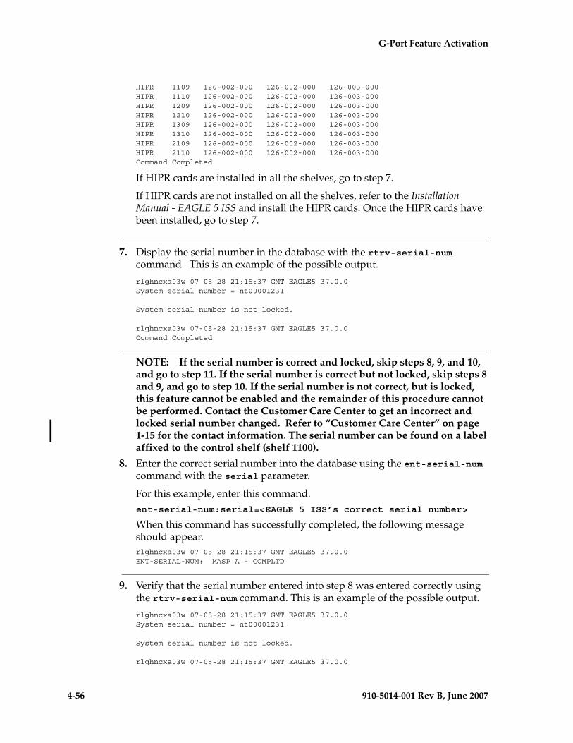
4-56 910-5014-001 Rev B, June 2007
- Draft - G-Port Feature Activation
HIPR 1109 126-002-000 126-002-000 126-003-000HIPR 1110 126-002-000 126-002-000 126-003-000HIPR 1209 126-002-000 126-002-000 126-003-000HIPR 1210 126-002-000 126-002-000 126-003-000HIPR 1309 126-002-000 126-002-000 126-003-000HIPR 1310 126-002-000 126-002-000 126-003-000HIPR 2109 126-002-000 126-002-000 126-003-000HIPR 2110 126-002-000 126-002-000 126-003-000Command Completed
If HIPR cards are installed in all the shelves, go to step 7.
If HIPR cards are not installed on all the shelves, refer to the Installation Manual - EAGLE 5 ISS and install the HIPR cards. Once the HIPR cards have been installed, go to step 7.
7. Display the serial number in the database with the rtrv-serial-num command. This is an example of the possible output.
rlghncxa03w 07-05-28 21:15:37 GMT EAGLE5 37.0.0System serial number = nt00001231
System serial number is not locked.
rlghncxa03w 07-05-28 21:15:37 GMT EAGLE5 37.0.0Command Completed
NOTE: If the serial number is correct and locked, skip steps 8, 9, and 10, and go to step 11. If the serial number is correct but not locked, skip steps 8 and 9, and go to step 10. If the serial number is not correct, but is locked, this feature cannot be enabled and the remainder of this procedure cannot be performed. Contact the Customer Care Center to get an incorrect and locked serial number changed. Refer to “Customer Care Center” on page 1-15 for the contact information. The serial number can be found on a label affixed to the control shelf (shelf 1100).
8. Enter the correct serial number into the database using the ent-serial-num command with the serial parameter.
For this example, enter this command.ent-serial-num:serial=<EAGLE 5 ISS’s correct serial number>
When this command has successfully completed, the following message should appear.rlghncxa03w 07-05-28 21:15:37 GMT EAGLE5 37.0.0ENT-SERIAL-NUM: MASP A - COMPLTD
9. Verify that the serial number entered into step 8 was entered correctly using the rtrv-serial-num command. This is an example of the possible output.
rlghncxa03w 07-05-28 21:15:37 GMT EAGLE5 37.0.0System serial number = nt00001231
System serial number is not locked.
rlghncxa03w 07-05-28 21:15:37 GMT EAGLE5 37.0.0
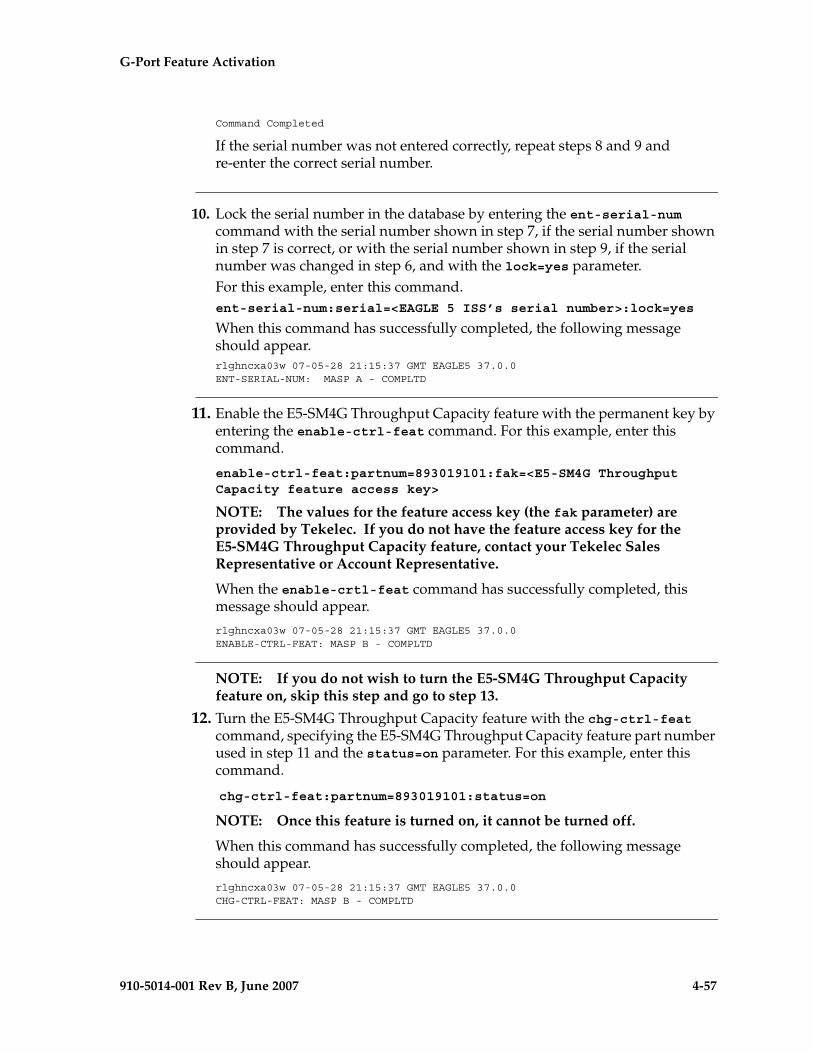
G-Port Feature Activation - Pr- Draft -elim
910-5014-001 Rev B, June 2007 4-57
Command Completed
If the serial number was not entered correctly, repeat steps 8 and 9 and re-enter the correct serial number.
10. Lock the serial number in the database by entering the ent-serial-num command with the serial number shown in step 7, if the serial number shown in step 7 is correct, or with the serial number shown in step 9, if the serial number was changed in step 6, and with the lock=yes parameter.For this example, enter this command.ent-serial-num:serial=<EAGLE 5 ISS’s serial number>:lock=yes
When this command has successfully completed, the following message should appear.rlghncxa03w 07-05-28 21:15:37 GMT EAGLE5 37.0.0ENT-SERIAL-NUM: MASP A - COMPLTD
11. Enable the E5-SM4G Throughput Capacity feature with the permanent key by entering the enable-ctrl-feat command. For this example, enter this command.
enable-ctrl-feat:partnum=893019101:fak=<E5-SM4G Throughput Capacity feature access key>
NOTE: The values for the feature access key (the fak parameter) are provided by Tekelec. If you do not have the feature access key for the E5-SM4G Throughput Capacity feature, contact your Tekelec Sales Representative or Account Representative.
When the enable-crtl-feat command has successfully completed, this message should appear.
rlghncxa03w 07-05-28 21:15:37 GMT EAGLE5 37.0.0ENABLE-CTRL-FEAT: MASP B - COMPLTD
NOTE: If you do not wish to turn the E5-SM4G Throughput Capacity feature on, skip this step and go to step 13.
12. Turn the E5-SM4G Throughput Capacity feature with the chg-ctrl-feat command, specifying the E5-SM4G Throughput Capacity feature part number used in step 11 and the status=on parameter. For this example, enter this command.
chg-ctrl-feat:partnum=893019101:status=on
NOTE: Once this feature is turned on, it cannot be turned off.
When this command has successfully completed, the following message should appear.
rlghncxa03w 07-05-28 21:15:37 GMT EAGLE5 37.0.0CHG-CTRL-FEAT: MASP B - COMPLTD
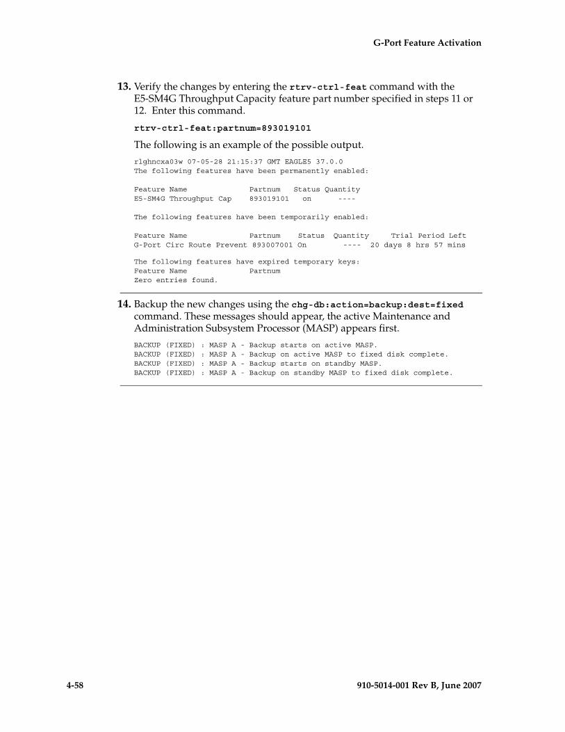
4-58 910-5014-001 Rev B, June 2007
- Draft - G-Port Feature Activation
13. Verify the changes by entering the rtrv-ctrl-feat command with the E5-SM4G Throughput Capacity feature part number specified in steps 11 or 12. Enter this command.
rtrv-ctrl-feat:partnum=893019101
The following is an example of the possible output.
rlghncxa03w 07-05-28 21:15:37 GMT EAGLE5 37.0.0The following features have been permanently enabled:
Feature Name Partnum Status QuantityE5-SM4G Throughput Cap 893019101 on ----
The following features have been temporarily enabled:
Feature Name Partnum Status Quantity Trial Period LeftG-Port Circ Route Prevent 893007001 On ---- 20 days 8 hrs 57 mins
The following features have expired temporary keys:Feature Name PartnumZero entries found.
14. Backup the new changes using the chg-db:action=backup:dest=fixed command. These messages should appear, the active Maintenance and Administration Subsystem Processor (MASP) appears first.
BACKUP (FIXED) : MASP A - Backup starts on active MASP.BACKUP (FIXED) : MASP A - Backup on active MASP to fixed disk complete.BACKUP (FIXED) : MASP A - Backup starts on standby MASP.BACKUP (FIXED) : MASP A - Backup on standby MASP to fixed disk complete.
910-5014-001 Rev B, June 2007 5-1
- Draft -
5
Maintenance and Measurements
Hardware Requirements ................................................................................ 5–1
EPAP Status and Alarms ................................................................................ 5–1
G-Port System Status Reports........................................................................ 5–4
Code and Application Data Loading............................................................ 5–5
G-Port Related Alarms.................................................................................. 5–12
G-Port Related UIMs..................................................................................... 5–16
G-Port Measurements ................................................................................... 5–18
Hardware Requirements
The G-Port feature requires DSM-based boards to run the VSCCP GPL. The EAGLE 5 ISS may be equipped with from 1 to 25 DSM boards to support G-Port.
CAUTION: Having a mix of SCCP and VSCCP card types is not permitted with the G-Port feature enabled, that is, VSCCP cards and SCCP cards cannot coexist in a system operating the G-Port feature. Refer to the Dimensioning Guide for EPAP Advanced DB Features Technical Reference for important information on the dimensioning rules and the DSM database capacity requirements.
EPAP Status and Alarms
EPAP has no direct means of accepting user input or displaying output messages on EAGLE 5 ISS terminals, so maintenance, measurements, and status information are routed through a DSM. EPAP sends two types of messages to the DSM: EPAP maintenance blocks and DSM status requests. Each is discussed in the following sections.
5-2 910-5014-001 Rev B, June 2007
- Draft - Maintenance and Measurements
EPAP Maintenance Blocks
The active EPAP generates and sends maintenance blocks to the primary DSM. One maintenance block is sent as soon as the IP link is established between the active EPAP and the primary DSM. Additional maintenance blocks are sent whenever the EPAP needs to report any change in status or error conditions. The information returned in maintenance blocks is included in the output of the rept-stat-mps and rept-stat-sccp commands.
The EPAP sends maintenance blocks that contain (at least) the following information.
• Status of EPAP 'A' - actual states are active, standby, and down (inoperative). Maintenance blocks include a field so this information can be forwarded to the EPAP A Device Control Block (DCB), where it is available for the output of the rept-stat-mps command.
• Status of EPAP 'B' - actual states are active, standby, and down (inoperative). Maintenance blocks include a field so this information can be forwarded to the EPAP B DCB, where it is available for the output of the rept-stat-mps command.
• Identification of active EPAP - a field to identify the active EPAP.
• Congestion indicator - an indicator showing provisioning link congestion. The link between the EPAPs and the external source of provisioning data can become congested in high provisioning traffic situations. When this occurs and subsequently as the congestion clears, the EPAP sends maintenance blocks to the DSM. The EPAP must ensure that no more than one maintenance block per second is sent to the primary DSM if the only reason is to report a change in congestion status.
• Alarm conditions - an error code field. If the EPAP needs to report an alarm condition, it puts an appropriate UAM identifier in this field.
• Current MPS database size - a field indicating the current RTDB size. The DSM uses this information to calculate the percentage of memory utilized by the RTDB.
DSM Status Requests
When the EPAP needs to know the status of a DSM, it can send a DSM Status Request to that DSM. Since status messages are sent over UDP, the EPAP broadcasts the DSM Status Request and all DSMs return their status to the EPAP.
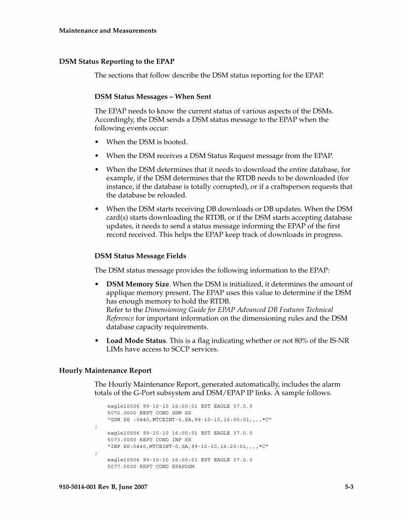
Maintenance and Measurements - Pre- Draft -minary -
910-5014-001 Rev B, June 2007 5-3
DSM Status Reporting to the EPAP
The sections that follow describe the DSM status reporting for the EPAP.
DSM Status Messages – When Sent
The EPAP needs to know the current status of various aspects of the DSMs. Accordingly, the DSM sends a DSM status message to the EPAP when the following events occur:
• When the DSM is booted.
• When the DSM receives a DSM Status Request message from the EPAP.
• When the DSM determines that it needs to download the entire database, for example, if the DSM determines that the RTDB needs to be downloaded (for instance, if the database is totally corrupted), or if a craftsperson requests that the database be reloaded.
• When the DSM starts receiving DB downloads or DB updates. When the DSM card(s) starts downloading the RTDB, or if the DSM starts accepting database updates, it needs to send a status message informing the EPAP of the first record received. This helps the EPAP keep track of downloads in progress.
DSM Status Message Fields
The DSM status message provides the following information to the EPAP:
• DSM Memory Size. When the DSM is initialized, it determines the amount of applique memory present. The EPAP uses this value to determine if the DSM has enough memory to hold the RTDB.Refer to the Dimensioning Guide for EPAP Advanced DB Features Technical Reference for important information on the dimensioning rules and the DSM database capacity requirements.
• Load Mode Status. This is a flag indicating whether or not 80% of the IS-NR LIMs have access to SCCP services.
Hourly Maintenance Report
The Hourly Maintenance Report, generated automatically, includes the alarm totals of the G-Port subsystem and DSM/EPAP IP links. A sample follows.
eagle10506 99-10-10 16:00:01 EST EAGLE 37.0.0 5072.0000 REPT COND GSM SS "GSM SS :0440,MTCEINT-0,SA,99-10-10,16:00:01,,,,*C"; eagle10506 99-10-10 16:00:01 EST EAGLE 37.0.0 5073.0000 REPT COND INP SS "INP SS:0440,MTCEINT-0,SA,99-10-10,16:20:01,,,,*C"; eagle10506 99-10-10 16:00:01 EST EAGLE 37.0.0 5077.0000 REPT COND EPAPDSM
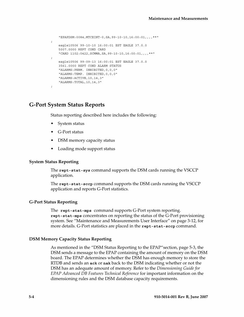
5-4 910-5014-001 Rev B, June 2007
- Draft - Maintenance and Measurements
"EPAPDSM:0084,MTCEINT-0,SA,99-10-10,16:00:01,,,,**"; eagle10506 99-10-10 16:00:01 EST EAGLE 37.0.0 5007.0000 REPT COND CARD "CARD 1102:0422,SCMMA,SA,99-10-10,16:00:01,,,,**"; eagle10506 99-09-13 16:00:01 EST EAGLE 37.0.0 3561.0000 REPT COND ALARM STATUS "ALARMS:PERM. INHIBITED,0,0,0" "ALARMS:TEMP. INHIBITED,0,0,0" "ALARMS:ACTIVE,10,14,3" "ALARMS:TOTAL,10,14,3";
G-Port System Status Reports
Status reporting described here includes the following:
• System status
• G-Port status
• DSM memory capacity status
• Loading mode support status
System Status Reporting
The rept-stat-sys command supports the DSM cards running the VSCCP application.
The rept-stat-sccp command supports the DSM cards running the VSCCP application and reports G-Port statistics.
G-Port Status Reporting
The rept-stat-mps command supports G-Port system reporting. rept-stat-mps concentrates on reporting the status of the G-Port provisioning system. See “Maintenance and Measurements User Interface” on page 3-12, for more details. G-Port statistics are placed in the rept-stat-sccp command.
DSM Memory Capacity Status Reporting
As mentioned in the “DSM Status Reporting to the EPAP“section, page 5-3, the DSM sends a message to the EPAP containing the amount of memory on the DSM board. The EPAP determines whether the DSM has enough memory to store the RTDB and sends an ack or nak back to the DSM indicating whether or not the DSM has an adequate amount of memory. Refer to the Dimensioning Guide for EPAP Advanced DB Features Technical Reference for important information on the dimensioning rules and the DSM database capacity requirements.
Maintenance and Measurements - Pre- Draft -minary -
910-5014-001 Rev B, June 2007 5-5
When the EPAP sends database updates to the DSMs, the update messages include a field that contains the new database memory requirements. Each DSM monitors the DB size requirements, and issues a minor alarm if the size of the DB exceeds 80% of its memory. If a database increases to the point that there is insufficient DSM memory, a major alarm is issued.
The rept-stat-mps:loc=xxxx command shows the amount of memory used by the RTDB as a percent of available DSM memory.
Loading Mode Support Status Reporting
The OAM application determines whether or not the system is in an unstable loading mode since it knows the state of all LIM, SCCP, and DSM cards in the system. When the loading mode is unstable, the rept-stat-sys command reports the existence of the unstable loading mode and the specific conditions that caused it. Refer to the “Loading Mode Support“section, page 5-6, for more details.
Code and Application Data Loading
DSM Code Loading
The EAGLE 5 ISS OAM code loads the DSM card.
EPAP Application Data Loading
The G-Port feature requires that (new) TDM-resident data tables be loaded in addition to those currently supported by EAGLE 5 ISS. The GPL and data loading support this additional table loading while maintaining support for loading the existing EAGLE 5 ISS tables.
In order to support both RTDB and EAGLE 5 ISS data loading, the VSCCP GPL verifies its hardware configuration during initialization to determine if it has the capacity to support the RTDB.
The VSCCP GPL application data loader registers all tables for loading, independent of the G-Port feature provisioning and main board / applique hardware configuration. As a result, load requests are always identical. During loading, multiple DSM load requests can then be combined into a single download, reducing the overall download time. The DSM card stores or discards RTDB table data based on whether or not it has RTDB-capable hardware for features like G-Port, G-Flex, EIR, and INP.
The OAM, on the other hand, downloads or sets memory boundaries for the G-Port options, entity, and service selector tables only if the G-Port feature is provisioned. When the G-Port feature is not provisioned, the OAM does not attempt to read these tables from disk. Instead, empty tables (i.e., tables without entries) are downloaded. All other tables requested for loading are read from disk and downloaded routinely.
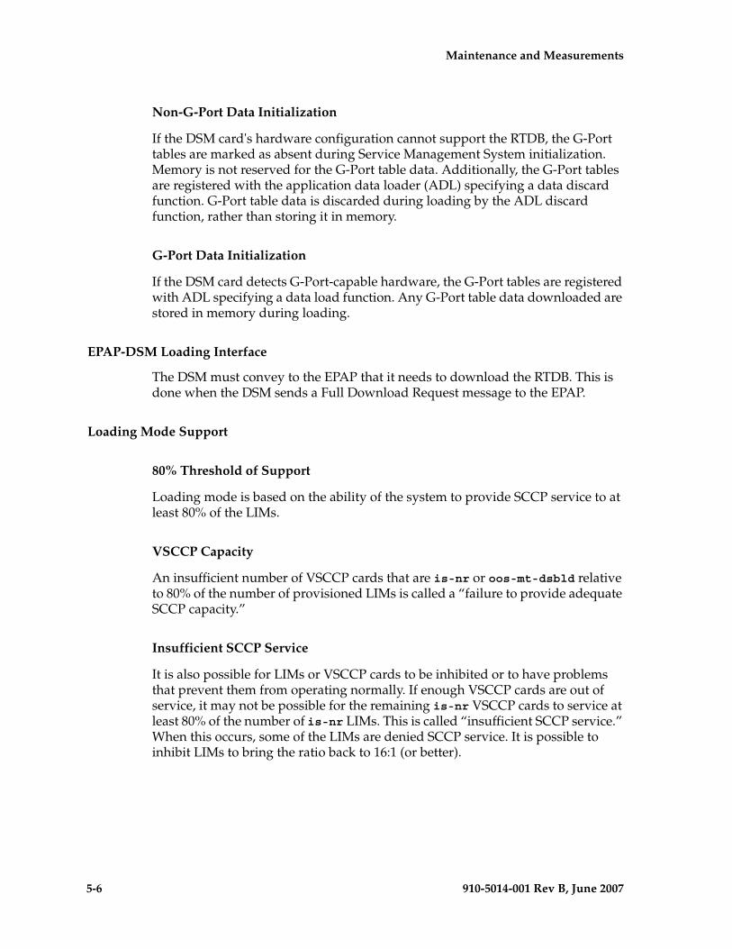
5-6 910-5014-001 Rev B, June 2007
- Draft - Maintenance and Measurements
Non-G-Port Data Initialization
If the DSM card's hardware configuration cannot support the RTDB, the G-Port tables are marked as absent during Service Management System initialization. Memory is not reserved for the G-Port table data. Additionally, the G-Port tables are registered with the application data loader (ADL) specifying a data discard function. G-Port table data is discarded during loading by the ADL discard function, rather than storing it in memory.
G-Port Data Initialization
If the DSM card detects G-Port-capable hardware, the G-Port tables are registered with ADL specifying a data load function. Any G-Port table data downloaded are stored in memory during loading.
EPAP-DSM Loading Interface
The DSM must convey to the EPAP that it needs to download the RTDB. This is done when the DSM sends a Full Download Request message to the EPAP.
Loading Mode Support
80% Threshold of Support
Loading mode is based on the ability of the system to provide SCCP service to at least 80% of the LIMs.
VSCCP Capacity
An insufficient number of VSCCP cards that are is-nr or oos-mt-dsbld relative to 80% of the number of provisioned LIMs is called a “failure to provide adequate SCCP capacity.”
Insufficient SCCP Service
It is also possible for LIMs or VSCCP cards to be inhibited or to have problems that prevent them from operating normally. If enough VSCCP cards are out of service, it may not be possible for the remaining is-nr VSCCP cards to service at least 80% of the number of is-nr LIMs. This is called “insufficient SCCP service.” When this occurs, some of the LIMs are denied SCCP service. It is possible to inhibit LIMs to bring the ratio back to 16:1 (or better).

Maintenance and Measurements - Pre- Draft -minary -
910-5014-001 Rev B, June 2007 5-7
Conditions That Create an Unstable Loading Mode
Current system implementation interrupts and aborts card loading upon execution of database chg commands. Loading mode support denies the execution of database chg commands when the system is in an unstable loading mode. An unstable loading mode exists when any of the following conditions are true:
• The system's maintenance baseline has not been established.
• Less than 80% of the number of LIMs provisioned are is-nr or oos-mt-dsbld.
• The number of is-nr and oos-mt-dsbld sccp cards is insufficient to service at least 80% of all provisioned LIMs.
• Insufficient SCCP service occurs when an insufficient number of is-nr VSCCP cards are available to service at least 80% of the number of is-nr LIMs.
• LIM cards are being denied SCCP service and any VSCCP cards are in an abnormal state (oos-mt, is-anr).
Actions Taken When the System is in an Unstable Loading Mode
• No affect on RTDB downloads or updates.
Unstable loading mode has no impact on RTDB downloads or the stream of RTDB updates.
• rept-stat-sys reports unstable loading mode.
When the loading mode is unstable, the rept-stat-sys command reports the existence of the unstable loading mode and the specific trigger that caused it.
• No database updates allowed.
When in an unstable loading mode, the EAGLE 5 ISS does not accept database updates. When updates are rejected, the reason is given as: E3112 Cmd Rej: Loading Mode unstable due to SCCP service is deficient.
The inh-card and alw-card commands can be used to alter SCCP service levels to achieve the 80% threshold. This can be repeated for each card until the system is able to supply SCCP services to at least 80% of the is-nr LIMs. The remaining 20% LIM or supporting VSCCP cards may remain out of service until the stream of database updates ceases. This stream of updates can be temporarily interrupted to allow the remaining 20% of the system to come in service.
Once a database has been loaded, that database can be updated (as long as the system is not in an unstable loading mode). However, if an update comes in
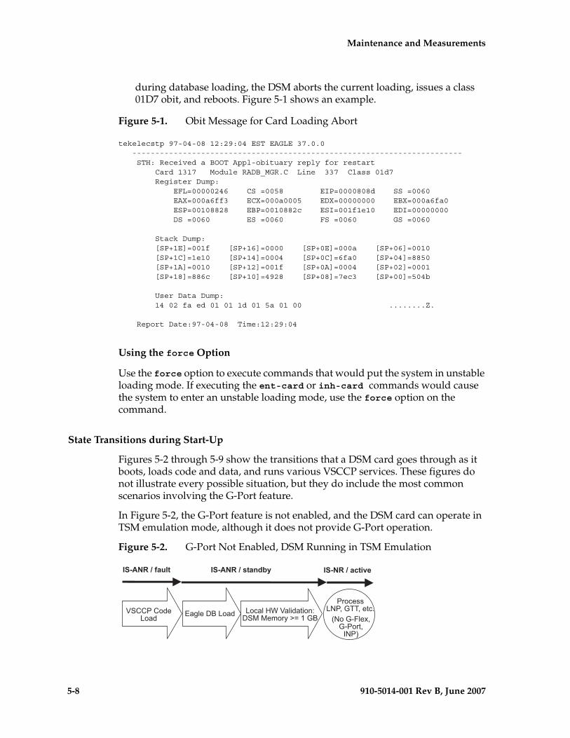
5-8 910-5014-001 Rev B, June 2007
- Draft - Maintenance and Measurements
during database loading, the DSM aborts the current loading, issues a class 01D7 obit, and reboots. Figure 5-1 shows an example.
Figure 5-1. Obit Message for Card Loading Abort
tekelecstp 97-04-08 12:29:04 EST EAGLE 37.0.0 ------------------------------------------------------------------------ STH: Received a BOOT Appl-obituary reply for restart Card 1317 Module RADB_MGR.C Line 337 Class 01d7 Register Dump: EFL=00000246 CS =0058 EIP=0000808d SS =0060 EAX=000a6ff3 ECX=000a0005 EDX=00000000 EBX=000a6fa0 ESP=00108828 EBP=0010882c ESI=001f1e10 EDI=00000000 DS =0060 ES =0060 FS =0060 GS =0060
Stack Dump: [SP+1E]=001f [SP+16]=0000 [SP+0E]=000a [SP+06]=0010 [SP+1C]=1e10 [SP+14]=0004 [SP+0C]=6fa0 [SP+04]=8850 [SP+1A]=0010 [SP+12]=001f [SP+0A]=0004 [SP+02]=0001 [SP+18]=886c [SP+10]=4928 [SP+08]=7ec3 [SP+00]=504b
User Data Dump: 14 02 fa ed 01 01 1d 01 5a 01 00 ........Z.
Report Date:97-04-08 Time:12:29:04
Using the force Option
Use the force option to execute commands that would put the system in unstable loading mode. If executing the ent-card or inh-card commands would cause the system to enter an unstable loading mode, use the force option on the command.
State Transitions during Start-Up
Figures 5-2 through 5-9 show the transitions that a DSM card goes through as it boots, loads code and data, and runs various VSCCP services. These figures do not illustrate every possible situation, but they do include the most common scenarios involving the G-Port feature.
In Figure 5-2, the G-Port feature is not enabled, and the DSM card can operate in TSM emulation mode, although it does not provide G-Port operation.
Figure 5-2. G-Port Not Enabled, DSM Running in TSM Emulation
����������� ������������
������������ � ����������������� �������������
������������������������������������������
����� !� ��"���"�#$��%�%�&��'�()�*��
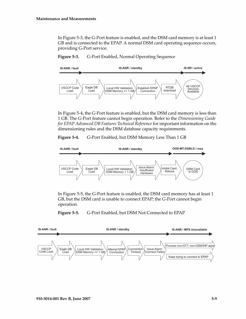
Maintenance and Measurements - Pre- Draft -minary -
910-5014-001 Rev B, June 2007 5-9
In Figure 5-3, the G-Port feature is enabled, and the DSM card memory is at least 1 GB and is connected to the EPAP. A normal DSM card operating sequence occurs, providing G-Port service.
Figure 5-3. G-Port Enabled, Normal Operating Sequence
In Figure 5-4, the G-Port feature is enabled, but the DSM card memory is less than 1 GB. The G-Port feature cannot begin operation. Refer to the Dimensioning Guide for EPAP Advanced DB Features Technical Reference for important information on the dimensioning rules and the DSM database capacity requirements.
Figure 5-4. G-Port Enabled, but DSM Memory Less Than 1 GB
In Figure 5-5, the G-Port feature is enabled, the DSM card memory has at least 1 GB, but the DSM card is unable to connect EPAP; the G-Port cannot begin operation.
Figure 5-5. G-Port Enabled, but DSM Not Connected to EPAP
������������ � ����������������� ���������������
����� !� ��"���"�#$��%�%�&��'�()�*��
+����,#����
������������
����������
����-�"�.���/���##���"�#
/��� �������0"���/0�"��-��
������������ � ����������������� �������������������
����� !� ��"���"�#$��%�%�&��'�1�*��
�#."-"�������+�-���
������������
���2��/���&$�#�233"�"�#� ���,���
��%�����"��44�
����������
������������ � ����������������� �������������� ����� �� �
������������
����������
����� !� ��"���"�#$��%�%�&��'�()�*��
/���&5����/���##���"�#
��##���"�#�"&��2�
���2��/���&$��##������"���
6��5���'"#�������##���������/�
��������#�#������#�#���%7�����55�
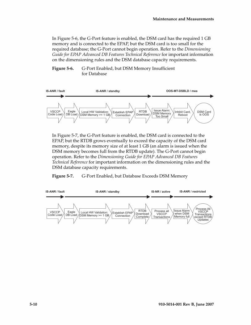
5-10 910-5014-001 Rev B, June 2007
- Draft - Maintenance and Measurements
In Figure 5-6, the G-Port feature is enabled, the DSM card has the required 1 GB memory and is connected to the EPAP, but the DSM card is too small for the required database; the G-Port cannot begin operation. Refer to the Dimensioning Guide for EPAP Advanced DB Features Technical Reference for important information on the dimensioning rules and the DSM database capacity requirements.
Figure 5-6. G-Port Enabled, but DSM Memory Insufficientfor Database
In Figure 5-7, the G-Port feature is enabled, the DSM card is connected to the EPAP, but the RTDB grows eventually to exceed the capacity of the DSM card memory, despite its memory size of at least 1 GB (an alarm is issued when the DSM memory becomes full from the RTDB update). The G-Port cannot begin operation. Refer to the Dimensioning Guide for EPAP Advanced DB Features Technical Reference for important information on the dimensioning rules and the DSM database capacity requirements.
Figure 5-7. G-Port Enabled, but Database Exceeds DSM Memory
������������ � ����������������� �������������������
������������
����������
����� !� ��"���"�#$��%�%�&��'�()�*��
����-�"�.���/���##���"�#
+����,#����
���2��/���&$��%�%�&��'�����&���
�#."-"�������+�-���
��%�����"��44�
������������ � ����������������� ����������!���!�����
������������
����������
����-�"�.���/���##���"�#
����� !� ��"���"�#$��%�%�&��'�()�*��
����������� ����
���#����"�#�
���2��/���&,.�#���%%�&��'�32��
��������/�� ����
���#����"�#�����5��+��85�����
���������������
+����,#������&5����
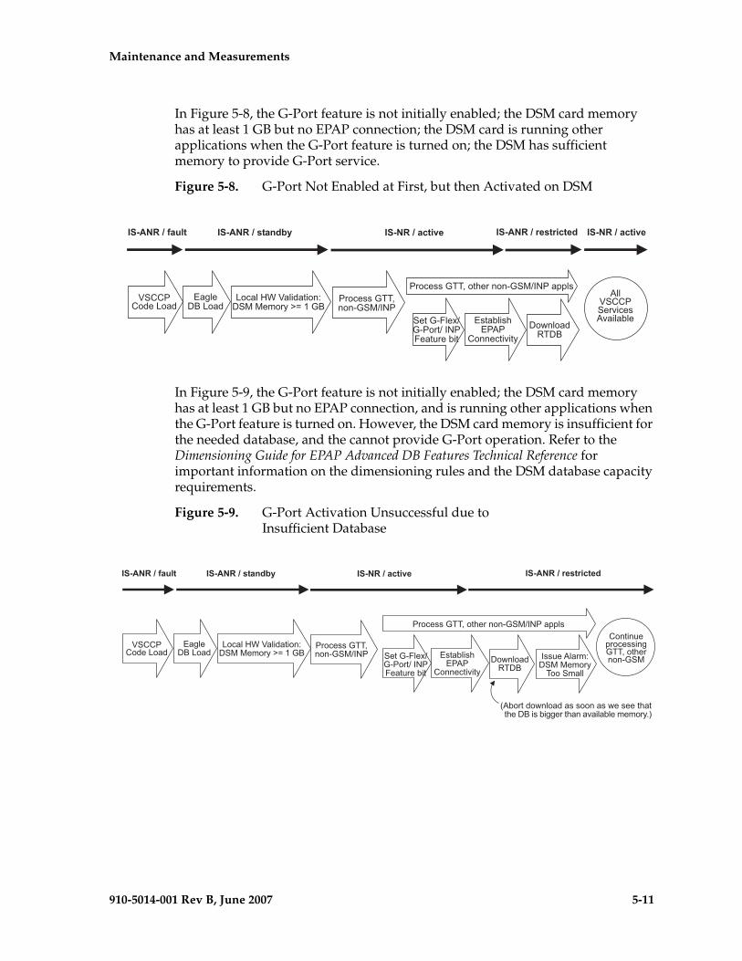
Maintenance and Measurements - Pre- Draft -minary -
910-5014-001 Rev B, June 2007 5-11
In Figure 5-8, the G-Port feature is not initially enabled; the DSM card memory has at least 1 GB but no EPAP connection; the DSM card is running other applications when the G-Port feature is turned on; the DSM has sufficient memory to provide G-Port service.
Figure 5-8. G-Port Not Enabled at First, but then Activated on DSM
In Figure 5-9, the G-Port feature is not initially enabled; the DSM card memory has at least 1 GB but no EPAP connection, and is running other applications when the G-Port feature is turned on. However, the DSM card memory is insufficient for the needed database, and the cannot provide G-Port operation. Refer to the Dimensioning Guide for EPAP Advanced DB Features Technical Reference for important information on the dimensioning rules and the DSM database capacity requirements.
Figure 5-9. G-Port Activation Unsuccessful due to Insufficient Database
������������ � ����������������� ����������!���!�����
������������
����������
���������������
����-�"�.��/�
��##���"0"�'��,#����+��
/�� �������0"���/0�"��-��
���������������
����������7������7��������2���-"�
����� !� ��"���"�#$��%�%�&��'�()�*��
������������#�#���%7���
���������������.���#�#���%7�����55��
���������� � ����������������� ����������!���!�����
������������
���������� ����-�"�.
��/���##���"0"�'
���������������
����� !� ��"���"�#$��%�%�&��'�()�*��
������������#�#���%7���
��#�"#2�5������"#��������.��#�#���%��,#����
+�����2��/���&$��%�%�&��'�����&���
�/-������,#�����������#����,�������.�����.����"��-"������.�#��0�"��-���&�&��'��
���������������.���#�#���%7�����55��
����������7������7��������2���-"�
5-12 910-5014-001 Rev B, June 2007
- Draft - Maintenance and Measurements
G-Port Related Alarms
Refer to the Maintenance Manual for a complete description and the associated corrective procedure for all G-Port related UAMs.
EPAP - DSM Connection Status
The EPAP and the DSM are connected over a 100-Mbit Ethernet link and use TCP/IP. If this connection is inoperative, the DSM generates an appropriate UAM. Loss of connectivity or inability of the EPAP to communicate (for example, hardware or software failure) is detected and reported within 10 seconds.
EPAP UAMs
The maintenance blocks from the EPAP have a field used to identify error message requests. The DSM processes the incoming maintenance blocks and generates the requested UAM. The actual EPAP UAMs are defined in the Maintenance Manual; the DSM only acts as a delivery agent.
DSM Failure
No new alarms have been created to report DSM failure. The existing card alarm UAM 013, Card is isolated from the system, indicates a DSM card failure. The DSM failure alarm is output to the Card Output Group.
DSM-EPAP Link
Two alarms are used to indicate the DSM-to-EPAP link status:
• 0084, IP Connection Unavailable (Major)
• 0085, IP Connection Available (Normal/Clearing)
The DSM-EPAP Link alarms are output to the Link Maintenance Output Group. See the Maintenance Manual for details on these UAM formats.
Example:
1 2 3 4 5 6 7 812345678901234567890123456789012345678901234567890123456789012345678901234567890 station1234 00-09-30 16:28:08 EST EAGLE 37.0.0-35.10.0** 3582.0084 ** VSCCP PORT B 1217 IP Connection Unavailable
Maintenance and Measurements - Pre- Draft -minary -
910-5014-001 Rev B, June 2007 5-13
DSM Hardware-Related Alarms
A major alarm appears when a DSM card does not have the hardware configuration required for the G-Port application. Loading the DSM card is automatically inhibited. Card alarms can be inhibited and uninhibited with the inh-alm and unhb-alm commands. The DSM Hardware-Related alarms are output to the Card Output Group.
A major alarm is displayed when a DSM card detects that its applique memory is at least 80% full. The actual memory usage can be displayed by entering the rept-stat-mps:loc=xxxx command.
Example:
1 2 3 4 5 6 7 812345678901234567890123456789012345678901234567890123456789012345678901234567890 station1234 99-09-30 16:28:08 EST EAGLE 37.0.0-31.7.0** 0012.0446 ** CARD 1108 VSCCP RTDB database capacity is 80% full
A critical alarm is generated when a DSM card detects that its applique memory is 95% full. Loading of the DSM card is automatically inhibited when it reaches 100% of capacity. The actual memory usage can be displayed by entering the rept-stat-mps:loc=xxxx command.
Example:
1 2 3 4 5 6 7 812345678901234567890123456789012345678901234567890123456789012345678901234567890 station1234 99-09-30 16:28:08 EST EAGLE 37.0.0-31.7.0*C 0012.0442 *C CARD 1108 VSCCP RTDB database capacity is 95% full
When the alw-card command is executed, loading of the DSM card is attempted. The following message appears, indicating that card loading is no longer inhibited.
Example:
1 2 3 4 5 6 7 812345678901234567890123456789012345678901234567890123456789012345678901234567890 station1234 00-09-30 16:28:08 EST EAGLE 37.0.0-35.10.00012.0423 CARD 1108 VSCCP Card reload attempted
DSM Database Audit Alarm
During an audit of the DSM cards, the status of the RTDB is examined and an alarm is raised when a corrupted database is found. When any RTDB database becomes corrupted, a major alarm is raised. The DSM Database Audit alarm is output to the Card Output Group.
5-14 910-5014-001 Rev B, June 2007
- Draft - Maintenance and Measurements
Example:
1 2 3 4 5 6 7 812345678901234567890123456789012345678901234567890123456789012345678901234567890 station1234 00-09-30 16:28:08 EST EAGLE 37.0.0-35.10.0** 0012.0443 ** CARD 1108 VSCCP RTDB Database is corrupted
DSM Database Alarms
During the operation of DSM cards, the status of databases is examined and alarms can be raised.
When a DSM card's RTDB is inconsistent (that is, DSM card’s birthdate and level do not match the active EPAP RTDB birthdate and level), a minor alarm is raised. The DSM Database alarms are output to the Card Output Group.
Example:
1 2 3 4 5 6 7 812345678901234567890123456789012345678901234567890123456789012345678901234567890 station1234 00-09-30 16:28:08 EST EAGLE 37.0.0-35.10.0* 0012.0444 * CARD 1108 VSCCP RTDB Database is inconsistent
When the RTDB database download is in-process or after an update faileds, the database is in an incoherent state. A alarm is raised.
Example:
1 2 3 4 5 6 7 812345678901234567890123456789012345678901234567890123456789012345678901234567890 station1234 00-09-30 16:28:08 EST EAGLE 37.0.0-35.10.0* 0012.0448 * CARD 1108 VSCCP RTDB Database is incoherent
When an inconsistent, incoherent, or corrupted DSM RTDB has been fixed when the DSM card is in an is-nr condition, an alarm is raised.
Example:
1 2 3 4 5 6 7 812345678901234567890123456789012345678901234567890123456789012345678901234567890 station1234 00-09-30 16:28:08 EST EAGLE 37.0.0-35.10.00012.0445 CARD 1108 VSCCP RTDB Database has been corrected
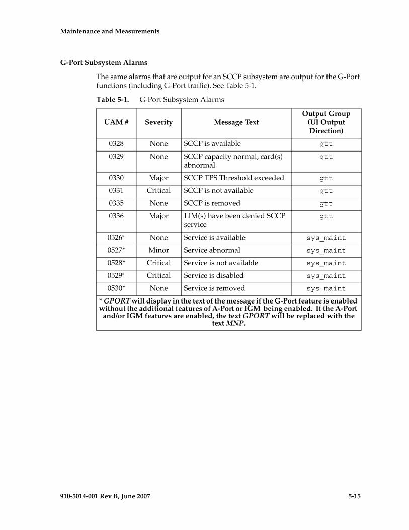
Maintenance and Measurements - Pre- Draft -minary -
910-5014-001 Rev B, June 2007 5-15
G-Port Subsystem Alarms
The same alarms that are output for an SCCP subsystem are output for the G-Port functions (including G-Port traffic). See Table 5-1.
Table 5-1. G-Port Subsystem Alarms
UAM # Severity Message TextOutput Group
(UI Output Direction)
0328 None SCCP is available gtt
0329 None SCCP capacity normal, card(s) abnormal
gtt
0330 Major SCCP TPS Threshold exceeded gtt
0331 Critical SCCP is not available gtt
0335 None SCCP is removed gtt
0336 Major LIM(s) have been denied SCCP service
gtt
0526* None Service is available sys_maint
0527* Minor Service abnormal sys_maint
0528* Critical Service is not available sys_maint
0529* Critical Service is disabled sys_maint
0530* None Service is removed sys_maint
* GPORT will display in the text of the message if the G-Port feature is enabled without the additional features of A-Port or IGM being enabled. If the A-Port
and/or IGM features are enabled, the text GPORT will be replaced with the text MNP.
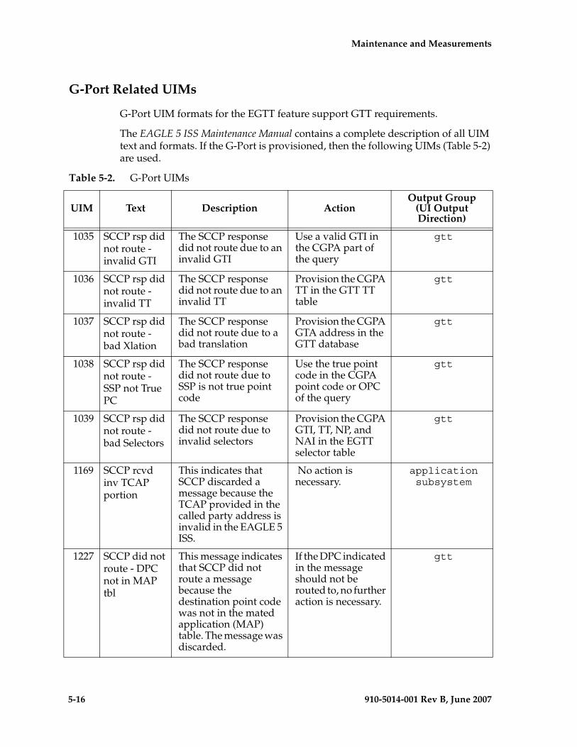
5-16 910-5014-001 Rev B, June 2007
- Draft - Maintenance and Measurements
G-Port Related UIMs
G-Port UIM formats for the EGTT feature support GTT requirements.
The EAGLE 5 ISS Maintenance Manual contains a complete description of all UIM text and formats. If the G-Port is provisioned, then the following UIMs (Table 5-2) are used.
Table 5-2. G-Port UIMs
UIM Text Description ActionOutput Group
(UI Output Direction)
1035 SCCP rsp did not route - invalid GTI
The SCCP response did not route due to an invalid GTI
Use a valid GTI in the CGPA part of the query
gtt
1036 SCCP rsp did not route - invalid TT
The SCCP response did not route due to an invalid TT
Provision the CGPA TT in the GTT TT table
gtt
1037 SCCP rsp did not route - bad Xlation
The SCCP response did not route due to a bad translation
Provision the CGPA GTA address in the GTT database
gtt
1038 SCCP rsp did not route - SSP not True PC
The SCCP response did not route due to SSP is not true point code
Use the true point code in the CGPA point code or OPC of the query
gtt
1039 SCCP rsp did not route - bad Selectors
The SCCP response did not route due to invalid selectors
Provision the CGPA GTI, TT, NP, and NAI in the EGTT selector table
gtt
1169 SCCP rcvd inv TCAP portion
This indicates that SCCP discarded a message because the TCAP provided in the called party address is invalid in the EAGLE 5 ISS.
No action is necessary.
application subsystem
1227 SCCP did not route - DPC not in MAP tbl
This message indicates that SCCP did not route a message because the destination point code was not in the mated application (MAP) table. The message was discarded.
If the DPC indicated in the message should not be routed to, no further action is necessary.
gtt
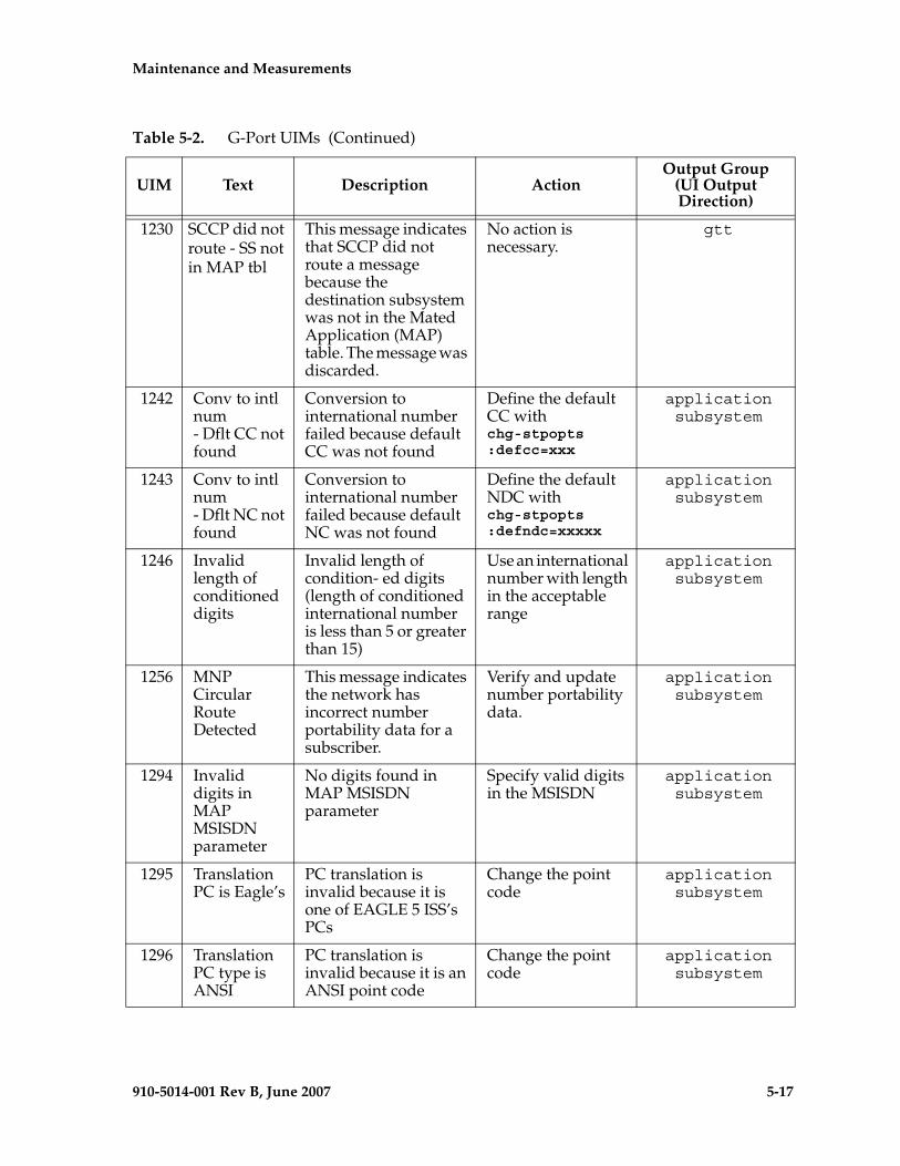
Maintenance and Measurements - Pre- Draft -minary -
910-5014-001 Rev B, June 2007 5-17
1230 SCCP did not route - SS not in MAP tbl
This message indicates that SCCP did not route a message because the destination subsystem was not in the Mated Application (MAP) table. The message was discarded.
No action is necessary.
gtt
1242 Conv to intl num - Dflt CC not found
Conversion to international number failed because default CC was not found
Define the default CC with chg-stpopts:defcc=xxx
application subsystem
1243 Conv to intl num - Dflt NC not found
Conversion to international number failed because default NC was not found
Define the default NDC with chg-stpopts:defndc=xxxxx
application subsystem
1246 Invalid length of conditioned digits
Invalid length of condition- ed digits (length of conditioned international number is less than 5 or greater than 15)
Use an international number with length in the acceptable range
application subsystem
1256 MNP Circular Route Detected
This message indicates the network has incorrect number portability data for a subscriber.
Verify and update number portability data.
application subsystem
1294 Invalid digits in MAP MSISDN parameter
No digits found in MAP MSISDN parameter
Specify valid digits in the MSISDN
application subsystem
1295 Translation PC is Eagle’s
PC translation is invalid because it is one of EAGLE 5 ISS’s PCs
Change the point code
application subsystem
1296 Translation PC type is ANSI
PC translation is invalid because it is an ANSI point code
Change the point code
application subsystem
Table 5-2. G-Port UIMs (Continued)
UIM Text Description ActionOutput Group
(UI Output Direction)
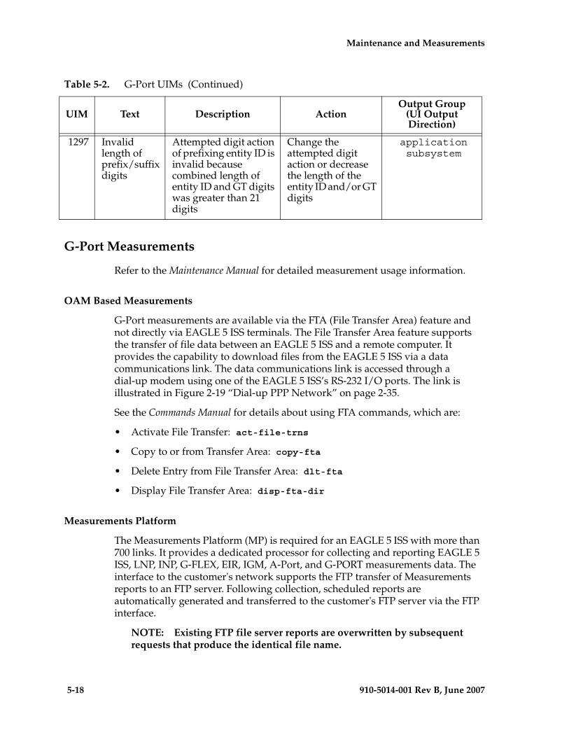
5-18 910-5014-001 Rev B, June 2007
- Draft - Maintenance and Measurements
G-Port Measurements
Refer to the Maintenance Manual for detailed measurement usage information.
OAM Based Measurements
G-Port measurements are available via the FTA (File Transfer Area) feature and not directly via EAGLE 5 ISS terminals. The File Transfer Area feature supports the transfer of file data between an EAGLE 5 ISS and a remote computer. It provides the capability to download files from the EAGLE 5 ISS via a data communications link. The data communications link is accessed through a dial-up modem using one of the EAGLE 5 ISS’s RS-232 I/O ports. The link is illustrated in Figure 2-19 “Dial-up PPP Network” on page 2-35.
See the Commands Manual for details about using FTA commands, which are:
• Activate File Transfer: act-file-trns
• Copy to or from Transfer Area: copy-fta
• Delete Entry from File Transfer Area: dlt-fta
• Display File Transfer Area: disp-fta-dir
Measurements Platform
The Measurements Platform (MP) is required for an EAGLE 5 ISS with more than 700 links. It provides a dedicated processor for collecting and reporting EAGLE 5 ISS, LNP, INP, G-FLEX, EIR, IGM, A-Port, and G-PORT measurements data. The interface to the customer's network supports the FTP transfer of Measurements reports to an FTP server. Following collection, scheduled reports are automatically generated and transferred to the customer's FTP server via the FTP interface.
NOTE: Existing FTP file server reports are overwritten by subsequent requests that produce the identical file name.
1297 Invalid length of prefix/suffix digits
Attempted digit action of prefixing entity ID is invalid because combined length of entity ID and GT digits was greater than 21 digits
Change the attempted digit action or decrease the length of the entity ID and/or GT digits
application subsystem
Table 5-2. G-Port UIMs (Continued)
UIM Text Description ActionOutput Group
(UI Output Direction)
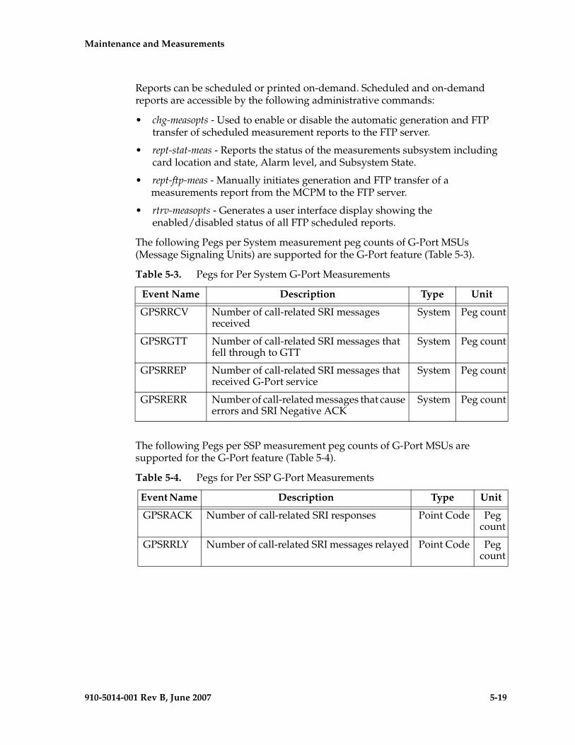
Maintenance and Measurements - Pre- Draft -minary -
910-5014-001 Rev B, June 2007 5-19
Reports can be scheduled or printed on-demand. Scheduled and on-demand reports are accessible by the following administrative commands:
• chg-measopts - Used to enable or disable the automatic generation and FTP transfer of scheduled measurement reports to the FTP server.
• rept-stat-meas - Reports the status of the measurements subsystem including card location and state, Alarm level, and Subsystem State.
• rept-ftp-meas - Manually initiates generation and FTP transfer of a measurements report from the MCPM to the FTP server.
• rtrv-measopts - Generates a user interface display showing the enabled/disabled status of all FTP scheduled reports.
The following Pegs per System measurement peg counts of G-Port MSUs (Message Signaling Units) are supported for the G-Port feature (Table 5-3).
The following Pegs per SSP measurement peg counts of G-Port MSUs are supported for the G-Port feature (Table 5-4).
Table 5-3. Pegs for Per System G-Port Measurements
Event Name Description Type Unit
GPSRRCV Number of call-related SRI messages received
System Peg count
GPSRGTT Number of call-related SRI messages that fell through to GTT
System Peg count
GPSRREP Number of call-related SRI messages that received G-Port service
System Peg count
GPSRERR Number of call-related messages that cause errors and SRI Negative ACK
System Peg count
Table 5-4. Pegs for Per SSP G-Port Measurements
Event Name Description Type Unit
GPSRACK Number of call-related SRI responses Point Code Peg count
GPSRRLY Number of call-related SRI messages relayed Point Code Peg count
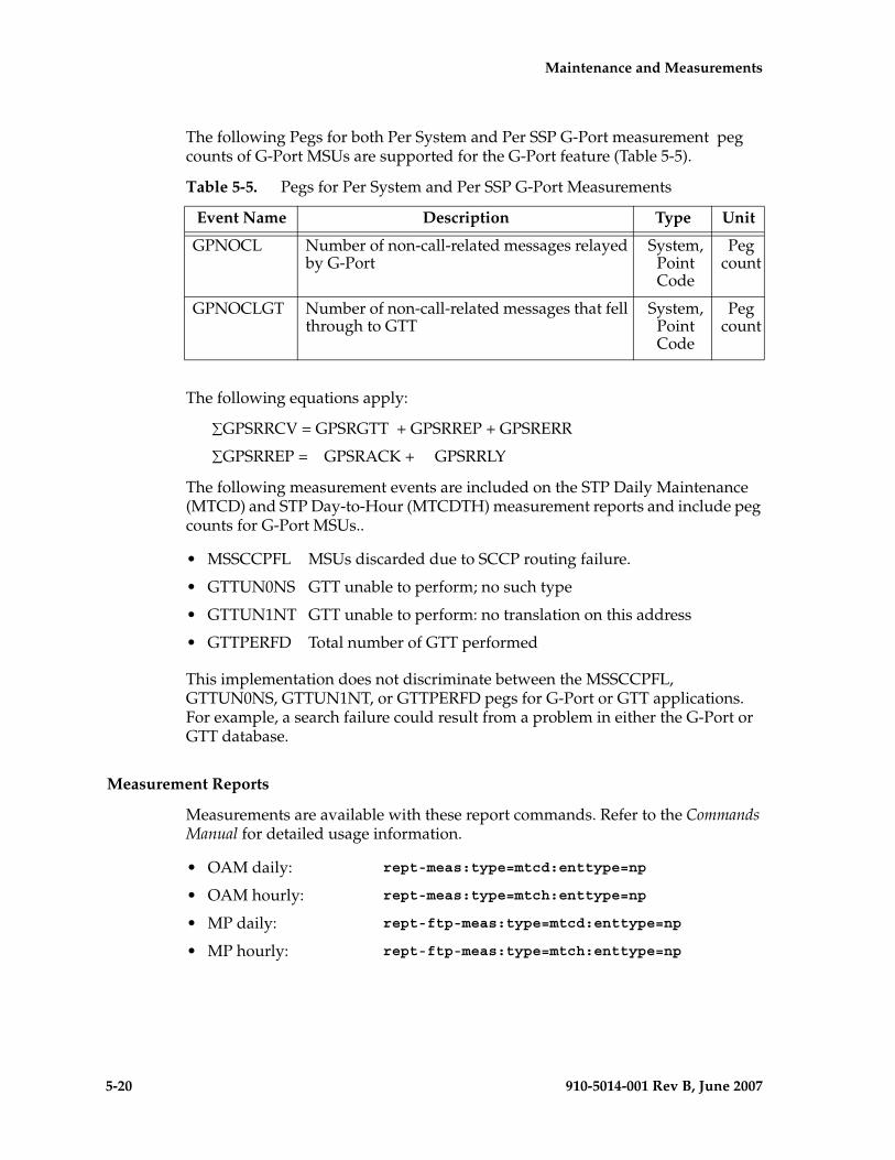
5-20 910-5014-001 Rev B, June 2007
- Draft - Maintenance and Measurements
The following Pegs for both Per System and Per SSP G-Port measurement peg counts of G-Port MSUs are supported for the G-Port feature (Table 5-5).
The following equations apply:
∑GPSRRCV = GPSRGTT + GPSRREP + GPSRERR
∑GPSRREP = GPSRACK + GPSRRLY
The following measurement events are included on the STP Daily Maintenance (MTCD) and STP Day-to-Hour (MTCDTH) measurement reports and include peg counts for G-Port MSUs..
This implementation does not discriminate between the MSSCCPFL, GTTUN0NS, GTTUN1NT, or GTTPERFD pegs for G-Port or GTT applications. For example, a search failure could result from a problem in either the G-Port or GTT database.
Measurement Reports
Measurements are available with these report commands. Refer to the Commands Manual for detailed usage information.
Table 5-5. Pegs for Per System and Per SSP G-Port Measurements
Event Name Description Type Unit
GPNOCL Number of non-call-related messages relayed by G-Port
System, Point Code
Peg count
GPNOCLGT Number of non-call-related messages that fell through to GTT
System, Point Code
Peg count
• MSSCCPFL MSUs discarded due to SCCP routing failure.
• GTTUN0NS GTT unable to perform; no such type
• GTTUN1NT GTT unable to perform: no translation on this address
• GTTPERFD Total number of GTT performed
• OAM daily: rept-meas:type=mtcd:enttype=np
• OAM hourly: rept-meas:type=mtch:enttype=np
• MP daily: rept-ftp-meas:type=mtcd:enttype=np
• MP hourly: rept-ftp-meas:type=mtch:enttype=np
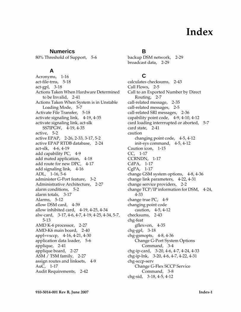
- Draft -
910-5014-001 Rev B, June 2007 Index-1
Numerics80% Threshold of Support, 5-6
AAcronyms, 1-16act-file-trns, 5-18act-gpl, 3-18Actions Taken When Hardware Determined
to be Invalid, 2-41Actions Taken When System is in Unstable
Loading Mode, 5-7Activate File Transfer, 5-18activate signaling link, 4-19, 4-35activate signaling link, act-slk
SS7IPGW, 4-19, 4-35active, 5-2active EPAP, 2-26, 2-33, 3-17, 5-2active EPAP RTDB database, 2-24act-slk, 4-6, 4-19add capability PC, 4-9add mated application, 4-18add route for new DPC, 4-17add signaling link, 4-16ADL, 1-16, 5-6administer G-Port feature, 3-2Administrative Architecture, 2-27alarm conditions, 5-2alarm totals, 3-17Alarms, 5-12allow DSM card, 4-39allow inhibited card, 4-19, 4-25, 4-34alw-card, 3-17, 4-6, 4-7, 4-19, 4-25, 4-34, 5-7,
5-13AMD K-6 processor, 2-27AMD-K6 main board, 2-40appl=vsccp, 4-16, 4-21, 4-30application data loader, 5-6applique, 2-41applique board, 2-27ASM / TSM family, 2-27assign routes and linksets, 4-9AuC, 1-17Audit Requirements, 2-42
Bbackup DSM network, 2-29broadcast data, 2-29
Ccalculates checksums, 2-43Call Flows, 2-5Call to an Exported Number by Direct
Routing, 2-7call-related message, 2-35call-related messages, 2-5call-related SRI messages, 2-36capability point code, 4-9, 4-10, 4-12card loading interrrupted or aborted, 5-7card state, 2-41caution
changing point code, 4-5, 4-12init-sys command, 4-5, 4-12
Caution icon, 1-15CC, 1-17CCRNDN, 1-17CdPA, 1-17CgPA, 1-17change GSM system options, 4-8, 4-36change link parameters, 4-22, 4-31change service providers, 2-2change TCP/IP information for DSM, 4-24,
4-33change true PC, 4-9changing point code
caution, 4-5, 4-12checksums, 2-43chg-feat
gflex=on, 4-35chg-gpl, 3-18chg-gsmopts, 4-8, 4-36
Change G-Port System Options Command, 3-4
chg-ip-card, 3-20, 4-6, 4-7, 4-24, 4-33chg-ip-lnk, 3-20, 4-6, 4-7, 4-22, 4-31chg-sccp-serv
Change G-Flex SCCP Service Command, 3-8
chg-sid, 3-18, 4-5, 4-12
Index
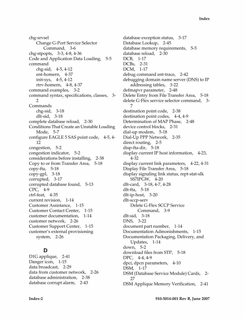
Index-2 910-5014-001 Rev B, June 2007
- Draft - Index
chg-srvselChange G-Port Service Selector
Command, 3-6chg-stpopts, 3-3, 4-8, 4-36Code and Application Data Loading, 5-5command
chg-sid, 4-5, 4-12ent-homern, 4-37init-sys, 4-5, 4-12rtrv-homern, 4-8, 4-37
command examples, 3-2command syntax, specifications, classes, 3-
2Commands
chg-sid, 3-18dlt-sid, 3-18
complete database reload, 2-30Conditions That Create an Unstable Loading
Mode, 5-7configure EAGLE 5 SAS point code, 4-5, 4-
12congestion, 5-2congestion indicator, 5-2considerations before installing, 2-38Copy to or from Transfer Area, 5-18copy-fta, 5-18copy-gpl, 3-18corrupted, 3-17corrupted database found, 5-13CPC, 4-9ctrl-feat, 4-35current revision, 1-14Customer Assistance, 1-15Customer Contact Center, 1-15customer documentation, 1-14customer network, 2-26Customer Support Center, 1-15customer’s external provisioning
system, 2-26
DD1G applique, 2-41Danger icon, 1-15data broadcast, 2-29data from customer network, 2-26database administration, 2-38database corrupt alarm, 2-43
database exception status, 3-17Database Lookup, 2-45database memory requirements, 5-5database reload, 2-30DCB, 1-17DCBs, 2-31DCM, 1-17debug command ent-trace, 2-42debugging domain name server (DNS) to IP
addressing tables, 3-22defmapvr parameter, 2-48Delete Entry from File Transfer Area, 5-18delete G-Flex service selector command, 3-
7destination point code, 2-38destination point codes, 4-4, 4-9Determination of MAP Phase, 2-48device control blocks, 2-31dial-up modem, 5-18Dial-Up PPP Network, 2-35direct routing, 2-5disp-fta-dir, 5-18display current IP host information, 4-23,
4-32display current link parameters, 4-22, 4-31Display File Transfer Area, 5-18display signaling link status, rept-stat-slk
SS7IPGW, 4-20dlt-card, 3-18, 4-7, 4-28dlt-fta, 5-18dlt-ip-host, 3-20dlt-sccp-serv
Delete G-Flex SCCP Service Command, 3-9
dlt-sid, 3-18DNS, 3-22document part number, 1-14Documentation Admonishments, 1-15Documentation Packaging, Delivery, and
Updates, 1-14down, 5-2download files from STP, 5-18DPC, 4-4, 4-9dpci, dpcn parameters, 4-10DSM, 1-17DSM (Database Service Module) Cards, 2-
27DSM Applique Memory Verification, 2-41
Index - Draft -
910-5014-001 Rev B, June 2007 Index-3
DSM card polls, 2-26DSM Code Loading, 5-5DSM Database Alarms, 5-14DSM Database Audit Alarm, 5-13DSM Database Levels and Reloading, 2-30DSM Failure, 5-12DSM Hardware-Related Alarms, 5-13DSM Main Board Verification, 2-40DSM Memory Capacity Status
Reporting, 5-4DSM Memory Size, 5-3DSM multicast hardware, 2-30DSM Networks, 2-33DSM Provisioning and Reload, 2-29DSM Reload Requirements, 2-30DSM Reloading Model, 2-29DSM status, 5-2DSM Status Message Fields, 5-3DSM Status Messages – When Sent, 5-3DSM Status Reporting to EPAP, 5-3DSM Status Requests, 5-2DSM/EPAP IP link alarms, 3-16DSM-based boards, 5-1DSM-EPAP Link, 5-12DSM-VxWorks-SCCP application, 2-27dual provisioning, 2-26
EE.164 MSISDN number (DN), 3-2E.164 numbers, 2-38EAGLE, 1-1EAGLE 5 SAS, 1-1EAGLE 5 SAS chg-db
Change Database Commands, 3-11EAGLE 5 SAS G-FLEX SCCP Service
Commands, 3-8EAGLE 5 SAS G-Port Commands, 3-1EAGLE 5 SAS G-Port Service Selector
Commands, 3-5, 3-10EAGLE 5 SAS G-Port System Options
Commands, 3-4EAGLE 5 SAS maintenance terminal, 2-37EAGLE Provisioning Application
Processors, 2-26ent-bp, 3-19ent-card, 3-18, 4-5, 4-6, 4-7, 4-16, 4-21, 4-30,
5-8
ent-dstn, 4-5, 4-14enter destination PC, 4-14enter DPC, 4-14enter G-Flex service selectors, 4-8, 4-38enter linkset, 4-15entering
init-sys command, 4-5, 4-13ent-homern, 4-37ent-ip-host, 3-20, 4-6, 4-7, 4-23, 4-32entity data, 2-37Entity Point Codes and Routes, 2-38ent-ls, 4-5, 4-15ent-map, 4-6, 4-18entries in the Internet Protocol host
table, 3-20ent-rte, 4-5, 4-17ent-slk, 4-5, 4-16ent-srvsel, 4-8, 4-38
Enter G-Port Service Selectors Command, 3-5
ent-trace, 2-42, 3-2EPAP, 1-17, 2-26EPAP - DSM Connection Status, 5-12EPAP 'A', 5-2EPAP 'B', 5-2EPAP (EAGLE Provisioning Application
Processor), 2-26EPAP A, 2-29EPAP Application Data Loading, 5-5EPAP architecture, 2-26EPAP automatically updates PDB, 2-26EPAP B, 2-29EPAP Continuous Reload, 2-29EPAP IP addresses in DSM network, 2-34EPAP IP Addresses in the DSM
Network, 2-34EPAP Maintenance Blocks, 5-2EPAP network addresses, 2-34EPAP Status and Alarms, 5-1EPAP Status and Error Reporting via
Maintenance Blocks, 2-31EPAP Sync Network, 2-33EPAP UAMs, 5-12EPAP UIMs, 5-18EPAP-DSM Loading Interface, 5-6ept-stat-epap, 2-31equipment damage, 1-15ES, 1-17
Index-4 910-5014-001 Rev B, June 2007
- Draft - Index
ETSI, 1-17ETSI GSM 03.03 standard, 2-5ETSI GSM 03.66 standard, 2-2ETSI standards, 2-4exception status, 3-17
FFeature Activation Overview, 4-4Feature Description, 2-1, 2-2File Transfer Area, 5-18force option, 5-8fourth octet, 2-34FTA, 5-18FTR, 1-17
GGDB, 1-17GDB requirements, 2-40General Procedure for G-Flex
Activation, 4-3, 4-4General Purpose Service Module II card, 2-
42General Requirements, 2-40GFDB, 1-17G-Flex, 1-17G-Flex Capability point Codes, 2-52G-Flex Re-Route Summary, 2-53G-Flex Re-routing, 2-51Global System for Mobile
communications, 2-2Global Title digits (GT), 3-3global title domain, 3-7global title information, 2-6Global Title Translation, 1-1Globalcast Communications, 2-28GMSC, 1-17GMSCA, 2-9GPDB, 2-9GPL, 1-17G-Port, 1-17G-Port Activation Unsuccessful due to
Insufficient Database, 5-11G-Port Considerations, 2-38G-Port Data Initialization, 5-6G-Port database audit, 2-26G-Port Enabled, but Database Exceeds DSM
Memory, 5-10
G-Port Enabled, but DSM Memory Insufficient for Database, 5-10
G-Port Enabled, but DSM Memory Less Than 1 GB, 5-9
G-Port Enabled, but DSM Not Connected to EPAP, 5-9
G-Port Enabled, Normal Operating Sequence, 5-9
G-Port Feature Activation, 4-1G-Port Loading Mode Support, 2-42G-Port Measurements, 5-18G-Port measurements, 3-15G-Port Message Handling, 2-49G-Port Message Relay messages, 2-38G-Port MNP feature, 1-1, 2-2G-Port MNP Overview, 2-2G-Port Node in GSM Network, 2-37G-Port Not Enabled at First, but then
Activated on DSM, 5-11G-Port Not Enabled, DSM Running in TSM
Emulation, 5-8G-Port Protocol, 2-43G-Port selector table, 2-40G-Port Status Reporting, 5-4G-Port Subsystem Alarms, 5-15G-Port system options (gsmopts), 3-4G-Port System Status Reports, 5-4G-Port traffic alarms, 5-15G-Port UIMs, 5-16GPSM-II, 2-42group code, 4-9GSM, 1-17, 2-2GSM 03.66, 2-39GSM 09.02, 2-39GSM network operators, 1-1GSM networks, 1-1gsmopts commands, 3-4GSMOPTS table, 3-3, 3-4GTA, 1-17GTAI, 1-17GTI, 1-17GTT, 1-1, 1-17GTT selectors, 2-40
Hhardware configuration, 2-41hardware configuration required, 5-13
Index - Draft -
910-5014-001 Rev B, June 2007 Index-5
Hardware Requirements, 5-1hexadecimal digits, 2-38high provisioning traffic situations, 5-2high-traffic situations, 2-27HLR, 1-17HLR translation, 2-36HLRB, 2-6, 2-9host=epap-a, 4-23, 4-32Hourly Maintenance Report, 5-3
IIAM, 1-18IAM message, 2-6, 2-7identify active EPAP, 5-2identify error message requests, 5-12import/export traffic, 2-32imported numbers, 1-1IMSI, 1-18, 2-2, 2-35IMSI number, 4-2IN, 1-18INAP, 1-18IN-based MNP, 2-4incoherent, 3-17inconsistent, 3-17incremental loading, 2-30incremental update, 2-30incremental updates, 2-29indirect routing, 2-5INE, 2-9, 2-10inh-alm, 3-19, 5-13inh-card, 3-17, 4-7, 4-27, 5-7, 5-8inhibit LIMs, 5-6init-card, 4-9, 4-39initializing DSM cards, 2-28init-sys, 4-5, 4-13init-sys command
caution, 4-5, 4-12re-entering, 4-5, 4-13
inoperative, 5-2INP, 1-18Install, 4-29Insufficient SCCP Service, 5-6Integrated Signaling System, 1-1intercepting MAP messages, 2-5International Mobile Station Identifier, 2-2international MSISDNs, 2-44international number, 2-6
Internet Protocol host table, 3-20Interrogating Network Entity, 2-9, 2-10Introduction to G-Port, 1-1invalid hardware configuration, 2-41IP, 1-18, 2-28IP host table, 3-20IP link alarms, 3-16IP link established, 5-2IP Multicast, 2-28ipaddr=192.168.122.nnn, 4-23, 4-32ISDN, 1-18ISUP NP with EPAP Call Flows, 2-19ISUP NP With EPAP for All Other Cases, 2-
22ITU, 1-18ITU national duplicate PC, 4-9ITU national point code, 4-9ITUDUPPC, 4-9
LLIM, 1-18LIMs, 2-42LIMs denied SCCP service, 5-6link alarms, 3-16link congestion, 5-2Link Interface Module, 2-42linksets assigned, 4-9list supported pass commands, 3-23LNP, 1-1, 1-18load balancing, 2-27Load Mode Status, 5-3loading incrementally, 2-30Loading Mode Support, 5-6Loading Mode Support Status
Reporting, 5-5loc parameter, 4-16loc=1103, 4-16, 4-21, 4-30Local Memory Validation, 2-41Local Number Portability, 1-1local provisioning terminal, 2-26logical link between MSISDN number and
IMSI, 4-2loss of connectivity, 2-28LSS, 1-18
Mmain board, 2-40
Index-6 910-5014-001 Rev B, June 2007
- Draft - Index
main DSM network, 2-29Maintenance, 2-40Maintenance and Measurements, 5-1Maintenance and Measurements User
Interface, 3-12maintenance application traffic, 2-33maintenance blocks, 5-2Maintenance Commands, 2-42, 3-12maintenance releases, 1-14maintenance terminal, 2-37Manual Organization, 1-2MAP, 1-18MAP messages, 1-1MAP Phase Determination, 2-48MAS, 1-18Mated Application Considerations, 2-37mated application table, 2-37mated pair configuration, 2-26maximum number length, 2-5MCAP, 1-18MDN, 1-18MEA, 1-18, 2-41Measurement Reports, 5-20measurements, 3-15memory requirements, 5-5Message Discrimination, 2-43, 2-55message relay, 2-5message relay function, 1-1Message Relay GT address, 2-10, 2-11Message Relay messages, 2-38Message Signaling Unit, 2-42MGT, 1-18MIN, 1-18mismatch of data, 2-37Mismatch of Equipment and Attributes, 2-
41MMI, 1-18MNP, 1-18, 2-2MNP Circular Route Prevention, 2-2MNP-SRF, 2-6, 2-35, 2-57MNP-SRFA, 2-10, 2-11MNP-SRFB, 2-9, 2-11MO/MT Call to a Number Not Known to be
Ported (Direct Routing), 2-8Mobile Number Portability, 1-1, 2-2Mobile Originated FSM from Contract, 2-
12Mobile Originated FSM from Prepaid, 2-14
Mobile Originated/Terminated Call to an Exported Number (Direct Routing), 2-7
Mobile Station international ISDN number, 2-2
mobile subscriber, 2-35Mobile Terminated Call by Indirect
Routing, 2-6Mobile Terminated Call to Non-ported or
Imported Number (Indirect Routing), 2-6
MPS, 1-18MPS/EPAP Platforms for Provisioning G-
Port, 2-25MSC, 1-18MSISDN, 1-18, 2-2, 2-6MSISDN number, 2-43, 2-44, 4-2MSRN, 1-18MSU, 1-18MSU Trap and Trace Command, 3-2MSU trigger, 3-2MSUs, 2-42MTP, 1-19multicast hardware, 2-30multicast updates, 2-24multiple trigger criteria, 3-2MySQL, 2-24
Nnational MSISDNs, 2-44NC, 1-19NDC, 1-19network addresses, 2-34Network Connections, 2-31network operators, 1-1Network Perspectives, 2-35New Pegs for Per SSP G-Port
Measurements, 5-19New Pegs for Per System and Per SSP G-Port
Measurements, 5-20New Pegs for Per System G-Port
Measurements, 5-19Non-Call Related Message for Non-Ported
Number (Indirect Routing), 2-9Non-Call Related Message for Ported
Number (Indirect Routing), 2-10Non-Call Related Message for Ported or
Non-Ported Number (Direct
Index - Draft -
910-5014-001 Rev B, June 2007 Index-7
Routing), 2-10non-call related messages, 1-1, 2-5non-call-related message, 2-35Non-G-Port Data Initialization, 5-6non-ported case, 2-11NP, 1-19NP database lookup, 2-6NPA, 1-19npcfmti option, 4-11NPDB, 1-19NPV, 1-19NSD, 1-19nstall, 4-20Number Conditioning, 2-44number portability, 1-1, 2-2Numbering, 2-40
OOAI, 1-19OAM, 1-19OAM provisioning, 2-34OAP, 1-19Obit Message for Card Loading Abort, 5-8octet addresses, 2-34operator's provisioning system, 2-22OPS, 2-22Optimal Routing, 2-10original number range owner network, 2-6Origination point code, 3-3out-of-sync data, 2-37Overview, 1-1Overview of EPAP to DSM
Communications, 2-28
Pparameter
PCIchg-sid, 4-12
PCNchg-sid, 4-12
pass, 3-20, 4-7, 4-8, 4-25, 4-34cmd="arp", 3-22cmd="help", 3-23cmd="netstat", 3-21cmd="nslookup", 3-22cmd="Ping", 3-21
PCI parameter
chg-sid, 4-12PCN parameter
chg-sid, 4-12PDB, 1-19PDBA, 1-19PDBA import/export traffic, 2-32PDBI, 1-19, 2-22, 2-23Pegs for both Per System and Per SSP, 5-20Pegs per SSP measurement peg counts, 5-
19personal safety, 1-15PFS, 1-19ping parameter, 4-25, 4-34PLMN, 1-19, 2-35PMTC, 1-19point code, 4-12Portability Check for Mobile Originated
SMS, 2-17portability cluster, 2-35ported case, 2-11ported numbers, 1-1, 2-5ported subscriber, 2-35porting process, 2-35PPSMS Provisioning and Activation, 4-40PPSMS Without G-Port MNP, 2-58Prepaid Short Message Service, 2-2primary DSM, 5-2provide redundancy, 2-29Provisioning database, 2-24Provisioning Database Interface, 2-22, 2-23,
2-31provisioning DSM cards, 2-26provisioning link congestion, 5-2provisioning terminal, 2-26provisioning traffic situations, 5-2Public Land Mobile Network, 2-35
RReal-Time Memory Validation, 2-41recipient network, 2-35redundancy, 2-29re-entering init-sys command, 4-5, 4-13regulatory obligations, 1-1, 2-2reinitialize system, 4-13Related Publications, 1-2Reliable Multicast Transport Protocol-II, 2-
28
Index-8 910-5014-001 Rev B, June 2007
- Draft - Index
reload multiple DSMs, 2-29remote access, 2-26replace TSM card with DSM card, 4-20, 4-
29rept-meas, 3-15rept-stat-alm, 3-17rept-stat-card, 4-6, 4-7, 4-9, 4-19, 4-25, 4-28,
4-34, 4-39stat=nr, 4-27
rept-stat-db, 3-17rept-stat-epap, 2-42, 3-14, 5-2, 5-4, 5-13rept-stat-gpl, 3-18rept-stat-sccp, 3-13, 5-2, 5-4rept-stat-slk, 4-6, 4-20rept-stat-sys, 3-12, 5-4, 5-5, 5-7rept-stat-trbl, 3-16RMTP, 1-19RMTP channels, 2-29RMTP-II, 2-28RN or SP address (Entity ID), 3-2RN Prefix Deletion, 2-43, 2-44RN prefixes, 2-38RNIDN, 1-19RNNDN, 1-19RNSDN, 1-19roaming number, 2-8route table, 2-38routes and linksets assigned to the
DPCs, 4-9Routing Number, 2-6routing number prefixes, 4-37routing options, 2-5RS-232 I/O ports, 5-18RTDB, 1-19RTDB transactional database engine, 2-25rtrv-card, 3-18, 4-5, 4-6, 4-7, 4-16, 4-20, 4-22,
4-27, 4-28, 4-31rtrv-dstn, 4-4, 4-5, 4-10, 4-11, 4-14rtrv-gpl, 3-18rtrv-gsmopts
Retrieve G-Port System Options Command, 3-5
rtrv-homern, 4-8, 4-37rtrv-ip-card, 3-20, 4-6, 4-7, 4-24, 4-33rtrv-ip-host, 3-20, 4-6, 4-7, 4-23, 4-24, 4-32,
4-33rtrv-ip-lnk, 3-20, 4-6, 4-7, 4-22, 4-23, 4-31, 4-
32
rtrv-ls, 4-5, 4-15rtrv-map, 4-6, 4-11, 4-19rtrv-rte, 4-4, 4-6, 4-10, 4-11, 4-18rtrv-sccp-serv
Retrieve G-Flex SCCP Service Command, 3-9
rtrv-sid, 4-4, 4-5, 4-9, 4-14rtrv-slk, 4-5, 4-17rtrv-srvsel, 4-8, 4-38
Retrieve G-Flex Service Selector Command, 3-7
rtrv-stpopts, 3-3, 4-4, 4-11, 4-36run VSCCP GPL, 5-1
SSCCP, 1-20SCCP maintenance block, 2-40Scope and Audience, 1-2SCP, 1-20SDS, 1-20self identification of system, 4-9sequential steps to activate G-Flex, 4-1service interruptions, 1-15service provider number portability, 1-1, 2-
2Service State, 2-51Serviceability Hints, 2-37set trace, 3-3Signaling Relay Function, 1-1SIM, 1-20, 2-2SMS, 1-20SMS Prepaid Intercept Message
Handling, 2-57SNP, 1-20software release, 1-14software releases, 1-14SP, 1-20SPC, 1-20specify ITU national PC format, 4-11speed=10, 4-22, 4-31SRF, 1-1, 1-20SRF-based MNP, 2-4SRI, 1-20SRI-MNP, 2-39srvsel commands, 3-5SS7, 1-20SS7IPGW
Index - Draft -
910-5014-001 Rev B, June 2007 Index-9
activate signaling link, act-slk, 4-19, 4-35
display signaling link status, rept-stat-slk, 4-20
SSN, 1-20SSP, 1-20SSPI/SSPN, 3-3stage 1 loading, 2-30standby, 5-2standby EPAP, 2-26, 2-33, 3-17standby EPAP RTDB, 2-26State Transitions during Start-Up, 5-8status message, 2-29steps to activate G-Flex, 4-1STP, 1-20Subscriber Data Provisioning, 2-22Subscriber Data Provisioning
Architecture, 2-23subscriber data provisioning
architecture, 2-22Subscriber Identity Module, 2-2subscription network, 2-6System Debug Services (SDS)
Commands, 3-2system point code, 4-10system self-identification, 4-9System Status Reporting, 5-4
TTCAP, 1-20TCP, 1-20TCP/IP socket, 2-28TDM fixed disks, 2-42TDM-resident data tables, 5-5Tekelec Customer Care Center, 1-16threshold monitoring, 2-42trace, 3-3traffic situations, 5-2transitions of DSM card, 5-8trap messages, 3-2trap-and-trace function, 3-2trigger criteria, 3-3troubleshooting network interface and
routing configuration, 3-21troubleshooting private EPAP/DSM IP
network, 3-21true point code, 4-9
TSM, 1-20TT, 1-20type=dsm, 4-16, 4-21, 4-30
UUAM, 1-20UDB, 1-20UDP, 2-28UIM, 1-20UIM message, 2-37UIM messages, 5-16unhb-alm, 3-19, 5-13Unstable Loading Mode, 2-42Unsuccessful Delivery of Mobile Originated
FSM, 2-16upload process, 2-30user interface, 3-2user interface for maintenance and
measurements, 3-12user interface traffic, 2-32Using force Option, 5-8
VValidation of G-Port Hardware
Configuration, 2-40varying length numbers, 2-5verify and correct IP stack ARP tables, 3-22verify IS-NR card status, 4-19, 4-25, 4-34verify new link parameters, 4-23, 4-32VLR, 1-21VMSC, 1-21VMSCA, 2-8VSCCP, 1-21, 2-27VSCCP application, 2-40VSCCP Capacity, 5-6VSCCP GPL, 5-1VxWorks, 1-21VxWorks OS, 2-27
WWarning icon, 1-15

Index-10 910-5014-001 Rev B, June 2007
- Draft - Index