Embed Size (px)
Citation preview

DRAG REDUCING ADDITIVE INJECTION SKID BPCL
Page 1 of 35
DESIGN, SUPPLY, INSTALLATION AND COMMISSIONING OF DRA (Drag Reducing Additive - for improving pipeline flow) INJECTION SKID AT MUMBAI DESPATCH TERMINAL OF MUMBAI- MANMAD – BIJWASAN PIPELINE.
SECTION CONTENTS PAGE NO
I Instruction to Vendors 2
II Project Scope 3
III System Specifications 4
IV Inspection & testing 23
V BPCL’s obligations & special terms & conditions 24
VI Project Schedule 26
VII Delivery address 27
VIII Payment Terms 28
IX Warranties & Guarantees 29
X ANNEXURES
Annexure 1 – PLC DATA SHEETS 30
Annexure 2 – PLC I/O LIST 33
Annexure 3 - Data to be filled by vendor 34
List of spare parts to be provided by vendor 35
DRAG REDUCING ADDITIVE INJECTION SKID BPCL
Page 2 of 35
SECTION – I
INSTRUCTION TO VENDORS
Bharat Petroleum Corporation Limited (hereinafter referred to as BPCL) intends to install Drag
Reducing Additive (DRA) Injection Skid at Mumbai Despatch Terminal of Mumbai – Manmad –
Bijwasan Pipeline. This tender invites bids for providing Design, Supply, Installation and
Commissioning of DRA Injection Skid at Mumbai Despatch Terminal.
The scope of work under this tender is detailed in the subsequent sections.
Note:
1. Short listing of vendors will be subject to qualification of technical (PTR) & commercial
criteria enlisted in the bidder qualification criteria.
2. Pre bid meeting shall be called to clarify any doubts regarding the technical & commercial
terms & conditions of the tender. All vendors are requested to clarify any doubts before
submitting the bids.

DRAG REDUCING ADDITIVE INJECTION SKID BPCL
Page 3 of 35
SECTION – II
PROJECT SCOPE
DESIGN, SUPPLY, INSTALLATION AND COMMISSIONING OF DRA (Drag Reducing Additive for improving flow) INJECTION SKID AT MUMBAI DESPATCH TERMINAL OF MUMBAI- MANMAD –BIJWASAN PIPELINE.
1.0 PREAMBLE :
Bharat Petroleum Corporation Ltd., (BPCL) requires to increase the throughput of cross country
pipeline in Mumbai– Manmad pipeline section by using Drag Reducing Additive (DRA) in the
pipeline which is transporting various grades of finished petroleum products (MS/HSD/SKO)
from Mumbai Despatch Terminal.
2.0 SCOPE OF WORK: The scope of work of this contract shall be as follows,
i. Design, Supply, Installation and Commissioning of one number of DRA injection skid
which includes integration of various components such as air compressor , booster
pump , main injection pump, flow meter , additive tank etc inside air conditioned
insulated steel container at MMBPL Mumbai Dispatch Terminal along with the
commissioning spares and
ii. Carrying out the Site Acceptance Test (SAT) and providing necessary training to
operation staff at Mumbai regarding operation and maintenance of entire system
provided by the vendor.

DRAG REDUCING ADDITIVE INJECTION SKID BPCL
Page 4 of 35
SECTION-III
SYSTEM SPECIFICATIONS
(VENDOR TO CONFIRM & SPECIFY ALL THE REQUIRED DETAILS IN THE TECHNICAL BID)
3.0 SPECIFICATIONS REQUIRED FOR DRA INJECTION SKID: The DRA injection skid unit shall be mounted in an insulated shipping container confirming to
ISO standards of approximate size 6 meter length x 2.4 meter width x 2.6 meter height with
dual entrance facility. The injection skid unit shall have high pressure metering injection pump,
recirculation / booster pump and associated controls, instruments and communication devices.
Redundant injection pumps to ensure reliable chemical injection by automatically starting the
lag pump when the lead pump fails to deliver the required flow rate. An onboard
Programmable Logic Controller (PLC) to maintain a desired flow rate set either locally or
remotely and controls events and provides status back to the SCADA in control room. Internal
storage tank for chemical storage, recirculation lines to allow mixing of products for extending
its shelf life. Variable frequency Drives on each motor of high pressure injection pumps to
adjust flow rate in the range that would normally be expected in daily operations. Fixed speed
booster pump to feed injection pumps under pressure (this pump shall transfer product from
internal storage tank with a return line back to the storage tank).
BPCL requirement for the injection skid is mentioned below. In the Technical Bid Vendor shall
submit the details against each point for evaluation purpose along with a P&ID diagram of the
offered injection skid
It shall be noted that the injection skid shall be installed in Zone II, gas group IIA/IIB hazardous area as per IEC 60079 -1:2007 standard. Hence all equipments shall confirm to these specifications.
3.1 INJECTION SKID FEATURES :
i. Standard external dimensions of the proposed insulated injection skid container shall be of
approximate size 6 meter length x 2.4 meter width x 2.6 meter height and shall confirm to
ISO container standards- Vendor to specify the dimensions in meters for the external &
internal length, width and height for the insulated injection skid.
ii. High strength, long lasting corrosion resistant corrugated steel construction – Vendor to
specify details
iii. Gross weight of the Injection Skid - Vendor to specify
iv. Structural components of steel : Vendor to confirm

DRAG REDUCING ADDITIVE INJECTION SKID BPCL
Page 5 of 35
v. Container to be externally painted in off white color with high quality corrosion resistant
paint: Vendor to confirm
vi. Vendor shall provide flame proof air conditioning system for the optimum functioning of
PLC, VFD and automation controls & maintaining skid temperature below 24degC. The DRA
skid container walls shall be provided with suitable insulation for optimization of air
conditioning system. Vendor to further specify about the type and thickness of insulation
provided to minimise the temperature losses and details of the air conditioning equipment
and loads. The tonnage requirement of the AC shall be estimated by the vendor based on
the container dimensions, heat load of equipments, ambient temperature & shall be
submitted along with technical bid.
vii. Wicket door of full height and 1.2 meter width with see through glass pane and locking
arrangement to be provided - Vendor to specify details with dimensions.
viii. One side full opening split door of size about 2.6 m height x 2.4 meter width and outside
locking arrangement – Vendor to confirm.
ix. Foundation for injection skid. Vendor to mention about any requirement of foundation at
site.
Foundation drawing / details to be submitted.
x. Air ventilation system to be provided inside the injection skid by providing flame proof
ventilation blower for air out. Vendor to specify about air ventilation system provided in the
injection skid for safe working of personnel inside the skid. The flame proof motor used for
blower shall meet the following specifications:
a. Voltage: 230±10%, 1-Ph, 50Hz, Induction motor, Exd , IIA, IIB, T3, Zone II, S1
xi. The warranty period for the equipments provided in the Injection Skid shall be 12 months
from the date of receipt of skid at site. During the warranty period any problem with the
equipments shall be reported to the vendor and vendor shall arrange to resolve the issue
within a week. Vendor to confirm/ comply.
xii. Vendor shall consider minimum required commissioning spares for the smooth
commissioning of injection skid. The cost of commissioning spares to be included in the cost
of the Injection skid - Vendor shall confirm and provide list of the commissioning spares
considered.
xiii. Details of air compressor, explosion proof motor including pressurized air distribution
network considered by vendor. Vendor to specify details.
xiv. Vendor shall provide the schematic sketch and photographs of the proposed injection skid -
Vendor to confirm / comply.
xv. Vendor shall submit the servicing and maintenance manual of all the equipments of the
Injection skid and other supplied accessories - Vendor to confirm/ comply.
xvi. Vendor to submit a list of mandatory spares in the technical bid.

DRAG REDUCING ADDITIVE INJECTION SKID BPCL
Page 6 of 35
3.2 ELECTRICAL INSTALLATIONS i. Hazardous area classification to be used for all the equipments, instruments and electrical
systems, VFD, control panels etc shall be Zone 2, Gas group II A/ II B - Vendor to confirm &
comply.
ii. All electrical equipments shall be flameproof & shall be certified by
CCOE/CMRI/BASEEFA/LCIE/UL/FM & copy of the approval is to be submitted.
iii. BPCL shall provide single point 3-Ph 415Volt AC power supply along with neutral & earthing
point near DRA skid. Necessary flame proof JB to terminate the power supply cable of size
4Cx70SQMM is in vendor’s scope. Vendor to specify the total power requirement for the
injection skid.
iv. Explosion proof lighting inside the injection skid to be provided to maintain minimum lux
level of 150 to 200 - Vendors to comply/ confirm about the lighting fixtures details
provided inside and injection skid for proper illumination. Explosion proof lights shall
confirm to following specifications:
a. Voltage: 230±10%, 1-Ph, 50Hz, Induction motor, Exd , IIA, IIB, T3, Zone II
v. The internal wiring diagram with details shall be provided by the vendor. This shall include
the location and number of junction box(es), switch(es), socket(s), plug(s),internal wiring
layout , concealed wiring drawing etc - Vendor to confirm.
vi. Pressure switch for air compressor to be provided - Vendor to confirm & comply.
vii. Temperature controller for air compressor to be provided - Vendor to confirm & comply.
viii. Emergency Stop device (ESD) to be provided - Vendor to confirm
ix. All the internal wiring shall be through GI pipe conduits -Vendor to confirm
x. All the cable terminations shall be through double compression nickel plated brass cable
glands. – Vendor to confirm
xi. Each electrical equipment working below 110V shall have one distinct earthing connection
& working above 110V shall have two distinct earthing connections. – Vendor to confirm
xii. All individual earthing connections shall be connected with minimum of 4SQMM copper
flexible cable to a common earthing bus bar of 3mm (thick) x 3cm (width) mounted inside
DRA skid. Any connection with flexible earthing cable shall not be more than 5 meter. –
Vendor to confirm
xiii. The common earthing bus bar shall have provision to connect two earthing cables at site.
The skid shall have suitable size opening for earthing cable connection to earth pits at site.
– Vendor to confirm
xiv. Two number of flame proof plug in points along with its top of 15 A rating, single phase 230 Volts shall be provided. – Vendor to confirm

DRAG REDUCING ADDITIVE INJECTION SKID BPCL
Page 7 of 35
3.2.1 HIGH PRESSURE INJECTION PUMP
i. Remotely operated high pressure injection pump with one number of standby pump
confirming to latest edition of API 675. Separate piping connections for both these pumps
connected to main discharge piping and related isolation valves shall be provided - Vendor
to confirm. (Vendor to enclose main injection pump details which shall consist of pump
manufacturer, pump model, pump maintenance and operation manual and any other
details. Vendor shall also specify about the pump capacity for maximum / minimum flow
rate and maximum discharge pressure of the pump).
ii. Redundancy in the injection pump to ensure reliable chemical injection by automatically
starting the standby pump when the lead pump fails to deliver the required flow rate -
Vendor to confirm
iii. Pressure relief valves for each pump - Vendor to specify the details of pressure relief valves
along with their design and test pressures.
iv. Pressure metering – List of local pressure transmitters. Vendor to specify the list of local
pressure transmitters with their make and ranges.
v. Pressure transmitters for transmitting the data to control room. Vendor to specify the list
of pressure transmitters and their details such as make etc.
vi. Requirement of any pressure balancing arrangement to be specified. Vendor to specify
about pressure balancing arrangements such as any provision of accumulator diaphragm
type, any pre charging required according to line pressure.
vii. Details of injection pump discharge piping from main Injection pump discharge to Mumbai
- Washala Pipeline -Vendor to specify the details of the injection pump discharge piping.
viii. Details of the injection pump suction piping - Vendor to provide.
ix. Block valve on the beginning of the injection line and check valve at the end of the
injection line - Vendor to specify
x. Injection point connection with the main Mumbai - Washala pipeline section. Vendor shall
provide a suitable connection for injection of DRA through existing half Inch diameter SOR
flange of 900 # pressure rating.
xi. Operation and Maintenance manual for high pressure injection pump to be provided -
Vendor to confirm & comply.
xii. The On/Off indication of each high pressure injection pump shall be required in SCADA.
Vendor to specify
Injection Pump shall meet the following minimum requirements:
i. Type : Positive Displacement Pump

DRAG REDUCING ADDITIVE INJECTION SKID BPCL
Page 8 of 35
ii. Make : Neptune or equivalent reputed make of pump used for DRA service having
local service & spare support in India, subject to BPCL approval – Vendor to confirm
iii. Operating range : 0 – 100 kg/cm2
iv. Viscocity range of DRA fluid – 250 to 1200 cp
v. Density of DRA fluid – 900 to 950 kg/m3
vi. MOC - SS316
vii. Max press capability – Vendor to specify
viii. Power – Vendor to specify
ix. Flow rate - 0 to 55 LPH
x. Liquid temp - upto 50 degree centigrade
xi. With pressure relief valve
xii. With manual stroke adjusting screw for making change in flow rate
xiii. Pump shall be operated by variable frequency drive
xiv. RPM - 0 to 3000
xv. Coupling guard , base plate , foundation bolts etc complete
3.3 VARIABLE FREQUENCY DRIVE & MOTOR FOR PUMP Variable Frequency Drive (VFD) for the main injection pumps. Vendor to provide VFD details
which shall consist of manufacturer name, VFD model,VFD power input & output , VFD
maintenance ,efficiency , cooling requirement , operation manual and any other details.
VFD shall meet the following minimum requirements:
i. VFD shall be housed in Flame proof enclosure.
ii. Make: Reputed make such as ROCKWELL AUTOMATION/ ALSTHOM/
SIEMENS/YASKAWA/ABB & having local service and spare support in India , subject to
BPCL approval
iii. Input voltage : 3-Ph, 415V AC±10%, 50Hz±3%.
iv. Input voltage range : 3-Ph, 380 to 480V AC, 50Hz
v. Output voltage : 3-Ph, 0 to 480V AC, 0 to 50Hz
vi. Output current : Vendor to specify
vii. Output power : Vendor to specify
viii. Potential free Relay Contact : For ON-OFF state
ix. Indication: Input / Output supply ON. Speed/Frequency/output voltage
x. Output voltage adjustment: Yes locally and by using potentiometer as well as through 4-
20mA signal from PLC.

DRAG REDUCING ADDITIVE INJECTION SKID BPCL
Page 9 of 35
xi. VFD Protection : In built in VFD to self protect from faults such as over current, earth
fault, over load, phase loss, unbalance etc
xii. Motor Protection: In built in VFD to protect connected motor, from faults such as over
current, earth fault, over load, phase loss, unbalance etc.
xiii. Cooling : Natural – Vendor to confirm
xiv. Mode of operation : Manual/Local and Auto/Remote
xv. Dielectric strength: Above 1.5KV AC for all components.
xvi. Ambient temp : Max 50 Deg C
xvii. MTBF and MTTR: The VFD used shall be with proven field track record and shall be
suitable for unattended operation at remote location. The VFD design, internal
component layout and component rating shall ensure high MTBF and low MTTR
MTBF : Meam time before failure
MTRR : Mean time to repair.
THD:As per IEEE 519: < 5%
VFD final output rating shall be 20% higher than motor rating.
xviii. The motor supplied for main pump shall be inverter duty.
xix. The pump motor shall be any reputed make such as ABB/ Alsthom /Siemens / Dayton &
having local service and spare support in India , subject to BPCL approval.
3.4 MASS FLOW METER FOR METERING
Vendor to provide flow meter and to specify about specifications of flow meter and compatibility with different DRA products.
Mass flow meter shall meet the following minimum specifications:
i. Make : Flow meter shall be of Endress + Hauser , Promass-F model Make or Equivalent
reputed make having local service & spare support in India
ii. Flow meter which enables to measure from zero to 50 ltrs in rated pressure 0 bar to
100 bar with required accessories for flow control and accuracy.
iii. Flow Meter:-Compact dual tube system ,Medium Temperature up to +140 degree
centigrade, process pressure up to 100 BAR (1450 PSI) ,2 Line back lit display with push
button, device in compact or remote version
iv. Measuring principle: Coriolis
v. Sensor Features: Measurement Flow
vi. Transmitter features: Fully industry compliant,2 line backlit component
vii. Nominal diameter Range: DN 8 or 3/8"

DRAG REDUCING ADDITIVE INJECTION SKID BPCL
Page 10 of 35
viii. Wetted material:-Measuring tube 904L
: Connection 316 L
ix. Measured Variables: Mass flow, density, temperature, volume flow , corrected volume
flow etc
x. Max measured error: mass flow (liquid )+/-2%,volume flow( liquid )+/-0.25%
xi. Measuring Range: 0 kg/hr to 180000 kg/hr
xii. Max process pressure : PN100,CLASS600
xiii. Medium Temperature range: (-ve) 40 to (+ve) 140 degree Centigrade
xiv. Ambient Temperature Range : Standard (-ve)20 to (+ve)45degree Centigrade
xv. Sensor Housing Material: SS 304 / 316
xvi. Transmitter Housing material: Powder coated die cast Aluminium
xvii. Degree of protection: IP 67,TYPE 4X Enclosure, Remote transmitter :IP67
xviii. Display /Operation: 2 Line back lit display with push buttons
xix. Outputs: 0mA to 20mA (active) 4mA to 20mA (active/passive)
xx. Inputs: Status input
xxi. Digital: HART
xxii. Communication: PROFIBUS PA
xxiii. Power Supply: AC 85 to 260 V (45TO 65Hz)
xxiv. One additional piping arrangement with dummy spool & valve shall be provided for by
passing flow meter.
3.5 BOOSTER PUMP
i. One number of Air Operated Double Diaphragm (AODD) Booster pump for periodic
recirculation and maintaining suction pressure for injection pump to be provided.
Vendor to specify about the booster pump details, make, type of pump, manufacturer,
head and capacity. Details about the prime mover for the booster pump complete with
connectors, valves, hoses to be provided.
ii. Spare booster pump to be supplied .BPCL shall use this spare pump in case of any
problem in the existing booster pump so that the pump can be removed for
maintenance and replaced with spare pump. Vendor to consider spare booster pump
having the same specifications of the main booster pump.
iii. Operation and Maintenance manual for booster pump to be provided - Vendor to
submit.
iv. Provision of transmitting the On / Off indication of booster pump in SCADA - Vendor to
specify & confirm.

DRAG REDUCING ADDITIVE INJECTION SKID BPCL
Page 11 of 35
Booster Pump shall meet the following minimum specifications:
i. Booster pump make: Air operated double diaphragm Yamada pump model no NDP –
25BAN or equivalent reputed make used for DRA service and having local service &
spare support in India, subject to BPCL approval
ii. Discharge capacity: 185 LPM.
iii. Max operating pressure – Upto 7 BAR (100 PSI) – Vendor to confirm
iv. Inlet & outlet size: Min 1inch and as per requirement – Vendor to confirm
v. Air inlet (with ball valve) : 3/8 inch - Vendor to confirm
vi. Air outlet (with silencer): 3/4 inch - Vendor to confirm
vii. Maximum cycle per minute: 210 - Vendor to confirm
viii. Max dry suction lift : Minimum 18 feet - Vendor to confirm
ix. Max solid size : Atleast upto 4.8 mm - Vendor to confirm
x. MOC body : Aluminium -Vendor to confirm
xi. MOC diaphragm : Buna n (NBR) -Vendor to confirm
xii. MOC valve ball : Buna n (NBR) - Vendor to confirm
xiii. Max flow rate : 185LPM - Vendor to confirm
xiv. Min flow rate : 140 LPM - Vendor to confirm
xv. Max operating temperature: 100 deg c - Vendor to confirm
3.6 AIR COMPRESSOR
One no of flame proof motor driven air compressor shall be provided and placed inside DRA
skid with pressure switch, regulator and air manifolds for various uses such as driving the , air
hoses with following minimum requirements.
i. Compressor make: Model 2340 N5 Ingersoll Rand or Equivalent reputed make having
local service & spare support in India, subject to BPCL approval.
ii. Each unit includes a two-stage, 100% cast iron pump, mounted and wired magnetic
motor starter, ODP electric motor, automatic start stop control with a NEMA 1 pressure
switch mounted and an ASME coded air receiver tank. – Vendor to confirm
iii. Electric driven 2-stage model – Vendor to confirm
iv. Designed to run at high volumes and high pressure, without interruption
v. MOC: Solid, 100% cast iron construction and components - Vendor to confirm
vi. Motor capacity : Vendor to specify
vii. Cooling : Air cooled - Vendor to confirm

DRAG REDUCING ADDITIVE INJECTION SKID BPCL
Page 12 of 35
viii. Volumetric capacity : 14.3 ACFM @ 175 PSIG (ACFM – Actual Cubic Feet Per Minute)-
Vendor to confirm
ix. Receiver tank size : 80 gallons in vertical / horizontal configuration - Vendor to confirm
x. Weight: Vendor to specify
xi. Dimensions: Vendor to specify
xi. Supply and Installation of Air Hoses required for the supply of air driven booster pump.
xii. Supply of high pressure air hoses with piping and valve arrangement for stirring of the
Drag Reducing Additive as and when required.
xiii. Supply and Installation of Pressure switch for cut in and cut out for the operation of the
air compressor at 120 psi and 150 psi respectively. - Vendor to confirm
xiv. Pressure regulator for supply of air from air tank at 40 psi pressure for operation
purpose (supply of compressed air to air driven booster pump and for agitating of DRA
fluid). - Vendor to confirm
xv. Commissioning consumables such as lube oil for compressor crank case. Oil filters and
air filters 2 nos. each.- Vendor to confirm
xvi. The compressor motor shall have short circuit & overload protection.- Vendor to
confirm
xvii. The compressor shall have auto cut in & cut out based on tank pressure set point. All
necessary hardware or sensing devices shall be integral part of the unit and shall have
high MTBF and low MTTR.- Vendor to confirm
xviii. Operation and Maintenance manual of Compressor - Vendor to confirm
3.7 HOMOGENISATION UNIT:
i. Vendor to provide two numbers of hand held portable homogenization unit suitable for
mixing and reconditioning of DRA during long storage or after long shipping and stored
in Intermediate Bulk Containers. - Vendor to confirm
ii. The motor for homogenization unit shall be flame proof and working on single phase
230 V AC supply .The complete unit shall be supplied with necessary accessories
including flexible cable of 60 meters length. The unit shall be powered from the control
panel located inside the skid. Vendor to confirm
iii. The motor shall have short circuit & overload protection. Vendor to confirm
3.8 DRA STORAGE TANK:
i. A 5000 litres (approx) storage capacity tank of DRA shall be installed inside the injection
skid container. - Vendor to confirm

DRAG REDUCING ADDITIVE INJECTION SKID BPCL
Page 13 of 35
ii. Level transmitter indication to be provided for the DRA storage tank with 4- 20 mA
output & provision for connecting to SCADA shall be provided. - Vendor to confirm
iii. The equipments and necessary hoses/ piping arrangement for the safe transfer of DRA
chemical from the supplied barrel/ drums to the DRA storage tank to be provided by the
vendor. - Vendor to confirm
iv. Automated facility (complete with solenoid valves & timer) for agitating DRA in
tank/vessel installed inside DRA skid shall be done using the compressed air of the
compressor installed in DRA skid container. Vendor to confirm
3.9 SUCTION AND DISCHARGE PIPING & FITTINGS OF THE INJECTION UNIT. i. Vendor shall consider all the piping’s, valves & fittings in his scope for commissioning of
the DRA system - Vendor to confirm
ii. All the tube fittings & tube adapters, pipe fittings ,flange to tube fittings, valves,
connectors, medium & high pressure fittings shall be of Swagelok® - Vendor to
confirm
iii. The material of construction of entire skid piping / fitting / connectors / tubing
handling the DRA chemical additive shall be of SS 316. – vendor to confirm
iv. BPCL requires that the injection skid unit and all associated piping shall not get chocked
during operation and non operation of DRA injection system. The vendor shall
mention clearly about possibility of the chocking of the injection skid unit and all piping
during operation or non operation of the DRA injection system. The vendor shall also
mention about necessary procedures/ precautions to avoid chocking of the injection
skid (a) during operation of the DRA injection system (b) during non operation of DRA
injection system and (c) procedure for cleaning of the injection piping in case it gets
chocked for whatsoever the reason. – Vendor to provide
v. Y strainer of standard make of mesh 5 to be provided immediately after tank outlet
(min 2” size) with isolation valves across the strainer. Y strainer provided shall have
provision for quick removal & reinsertion after cleaning if required. – Vendor to
confirm
vi. Flushing point with isolation valve to be provided on common suction line. This flushing
point shall have arrangement to connect flexible pressure hose to transfer DRA back to
DRA tank for circulation of stagnant product in suction line. - Vendor to confirm
vii. Flushing point with isolation valve to be provided on common discharge line
immediately after flowmeter.- Vendor to confirm
viii. A provision to connect a small 10 litre portable steel container (including supply) on the
suction side of AODD pump with isolation valve shall be provided for flushing the

DRAG REDUCING ADDITIVE INJECTION SKID BPCL
Page 14 of 35
complete line with flushing fluid in case of any chocking / blocking of line caused due to
whatsoever reason - Vendor to confirm
ix. NRV’s provided in the system to be of minimum ½” size and should be of ball & spring
type with maximum cross sectional area to prevent chocking of DRA lumps inside the
NRV. NRV provided shall be such that it is easy to dismantle & reassemble the spring &
ball after cleaning if required without removing the entire NRV body from the line.-
Vendor to confirm
x. The vendor shall provide injection nozzle details. Please note that pipeline and valve
ratings are 900 # within the pump house and a half inch SOR flange of 900# is available
in discharge side of station piping for connection of DRA injection hoses/ pipe. BPCL
shall arrange to install the same at site on Mumbai - Washala pipeline section as
proposed by the vendor - Vendor to provide details.
xi. Vendor shall provide safety pressure relief valves in the system to take care of over
pressurization of the system due to any equipment failure or faulty operation.- Vendor
to confirm
xii. Vendor shall mention about safe procedure for transferring the DRA product from
supply of barrels/ drums etc to the DRA storage tank and necessary arrangements
provided - Vendor to specify.
xiii. All necessary special tools & tackles for carrying out any maintenance activity shall be
provided in a tool kit. - Vendor to confirm
3.10 DRA SKID AUTOMATION
i. A non redundant PLC is to be supplied, installed and commissioned with Input, output cards
& modbus serial & TCP IP communication cards. The PLC specifications are attached as
Annexure 2 & list of I/O details is attached as Annexure 3.
ii. Two numbers of VFD motor driven pump to be installed in DRA skid. The minimum
required specifications of VFD are mentioned in clause 3.3
iii. Run/stop indication & start/stop commands for these two pumps is to be configured in the
PLC.
iv. The flow meter output in 4 to 20 mA is to be configured in PLC to measure the actual flow
and also control the flow through VFD Motor-Pump.
v. A capacitive type level transmitter is to be supplied & installed in the DRA tank.
vi. The level signal to be connected and configured in PLC.
vii. Two nos. of intrinsically safe pressure transmitters are to be supplied & installed one at
common suction line (Range 0-20 PSI) & one at common discharge line (range 0-2000PSI)
of the VFD driven pumps & 4 to 20 mA signals to be connected and configured in PLC.

DRAG REDUCING ADDITIVE INJECTION SKID BPCL
Page 15 of 35
viii. A solenoid actuated valve along shall be supplied and installed for releasing the compressed
air into the DRA tank for agitation of DRA. The timer settings should be adjustable through
PLC. A bypass line along with necessary valves shall be provided across solenoid valve which
can be operated in case of solenoid valve failure.
ix. All the signals are to be mapped & transferred over modbus serial or TCP IP communication
to existing station PLC of ABB make, through RS485 modbus or LAN cable. Vendor has to
consider for the necessary Modbus RS485 & TCP IP communication card in the new PLC
System.
x. The RPM of VFD driven pumps shall be controlled by New PLC such that the required flow
rate is achieved using flow input from flow meter.
xi. The user shall have the facility to enter the flow meter set point on the LCD display touch
screen. So, vendor shall be responsible for supply the LCD Touch Screen for the same.
xii. The LCD display shall have the critical reading of all the equipments connected to PLC.
xiii. The LCD display shall have separate alarm log screen. In addition to LCD screens a
manual selector switches shall be provided to operate the skid manually without PLC.
xiv. A potentiometer shall be provided to adjust the VFD RPM manually in manual mode.
xv. DRA skid to be made operatable from existing ABB Station PLC through modbus serial or
TCP IP communication .
xvi. The dosing flow rate of DRA as per the set PPM shall be automatically derived from the
station product flow rate and density (these parameters to be accessed from ABB station
PLC).
xvii. DRA injection pump shall stop automatically after stoppage of main line flow.
3.11 INSTRUMENTATION MONITORING AND CONTROL FOR DRA
i. ABB PM 864A (AC800M Family) PLC is already in place at MMBPL MDT Despatch
terminal and being used by BPCL for its operation and interlocks of mainline pumping
system.
ii. For the monitoring and automatic control of DRA, following minimum signals of new
DRA system shall be integrated with BPCL’s ABB PLC system over modbus serial / TCP IP
communication.
iii. Vendor shall terminate all the transducers, sensors and input/output modules etc in the
skid PLC. All these signals shall be interfaced with BPCL’s ABB PLC over modbus serial /
TCP IP communication.
DRAG REDUCING ADDITIVE INJECTION SKID BPCL
Page 16 of 35
iv. BPCL will supply and lay an armoured serial/ LAN cable (as per requirement) from its
ABB PLC in control room to this new DRA skid.
v. Vendor shall provide support to ABB Engineer during interfacing of the signals. All the
logic shall be developed in DRA skid PLC. Required inputs such as Main Product flow rate
shall be interfaced with DRA skid PLC for calculation of required DRA flow rate.
vi. Based on the P & ID, Operation and Control philosophy submitted by vendor, BPCL will
configure a complete database and HMI of all the instrumentation and electrical signals
into its ABB PLC.
vii. The real time flow rate corrected volumetric (m3/hr), uncorrected volumetric (m3/hr),
mass flow rate (MT/hr) of mainline product pipeline are already available in the ABB PLC
and its HMI. The required PID controller for the flow control of DRA dosing shall be
configured in DRA skid PLC by vendor.
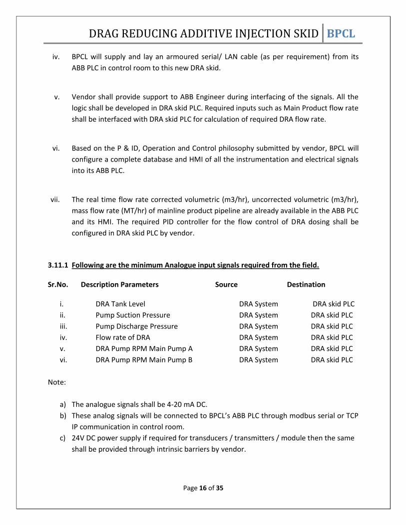
3.11.1 Following are the minimum Analogue input signals required from the field. Sr.No. Description Parameters Source Destination
i. DRA Tank Level DRA System DRA skid PLC
ii. Pump Suction Pressure DRA System DRA skid PLC
iii. Pump Discharge Pressure DRA System DRA skid PLC
iv. Flow rate of DRA DRA System DRA skid PLC
v. DRA Pump RPM Main Pump A DRA System DRA skid PLC
vi. DRA Pump RPM Main Pump B DRA System DRA skid PLC
Note:
a) The analogue signals shall be 4-20 mA DC.
b) These analog signals will be connected to BPCL’s ABB PLC through modbus serial or TCP
IP communication in control room.
c) 24V DC power supply if required for transducers / transmitters / module then the same
shall be provided through intrinsic barriers by vendor.

DRAG REDUCING ADDITIVE INJECTION SKID BPCL
Page 17 of 35
3.11.2 Following are the minimum Digital Input signals from the field
Sr. No. Description Parameters Source Destination
i. DRA Main Pump A running indication DRA System DRA skid PLC
ii. DRA Main Pump A Stop indication DRA System DRA skid PLC
iii. DRA Main Pump A Remote/Local Status DRA System DRA skid PLC
iv. DRA Main Pump B running indication DRA System DRA skid PLC
v. DRA Main Pump B Stop indications DRA System DRA skid PLC
vi. DRA Main Pump B Remote/Local Status DRA System DRA skid PLC
Note:
a. Vendor shall provide potential free contact with the rating of 230VAC, 5A and 24VDC,
1A for all the above digital inputs.
b. These digital input signals will be connected to BPCL’s ABB PLC through modbus serial or
TCP IP communication in control room.
3.11.3 Following are the minimum Digital Output parameters from BPCL’s ABB PLC to DRA skid in field: Sr. No. Description Parameter Source Destination i. DRA Main Pump A Start command Station PLC DRA System
ii. DRA Main Pump A Stop command Station PLC DRA System
iii. DRA Main Pump B Start command Station PLC DRA System
iv. DRA Main Pump B Stop command Station PLC DRA System
Note:
a) BPCL will provide continuous or pulse or latch or unlatched type as per requirement of
DRA vendor for output contacts with the rating of 230VAC, 5A and 24VDC, 1A to operate
the pumps from its HMI of ABB PLC in control room.
b) These digital output signals will be connected to BPCL’s ABB PLC through modbus serial
or TCP IP communication in control room.

DRAG REDUCING ADDITIVE INJECTION SKID BPCL
Page 18 of 35
3.11.4 Following are the Analog Output parameters to DRA skid in field: Sr. No. Description Parameters Source Destination
i. DRA Main Pump A RPM control Station PLC DRA System
ii. DRA Main Pump B RPM control Station PLC DRA System
Note:
a) These analog output signals will be connected to BPCL’s ABB PLC through modbus serial
or TCP IP communication in control room.
Based on above, Vendor to clearly specify about the system being provided for instrumentation
monitoring and control of DRA.
3.12 SYSTEM WORKING PHILOSOPHY
i. The skid can be operated in three modes as mentioned below:
a) Mode 1: Manual Mode:
In this mode DRA dosing pump RPM can be controlled by rotating the speed control
Knobs on respective VFD panels.
All trip interlocks as mentioned below shall remain online.
In this mode DRA dosing pump shall not get change over in 12 Hr.
Pumps can be operated either from PLC touch screen or from individual push
buttons provided on respective VFD panels.
b) Mode 2: Semi Auto Mode:
In this mode we need to feed set point for DRA flow rate in Ltr/Hr & select the
desired Pump to start.
DRA skid PLC shall control the VFD RPM automatically to achieve desired flow rate.
In this mode DRA dosing pumps shall get change over every 12 Hrs.
Pumps can be operated either from PLC touch screen or from individual push
buttons provided on respective VFD panels.
c) Mode 3: Fully Auto Mode:
In this mode we need to feed set point for DRA dosage in PPM & select the desired
Pump to start.
DRA skid PLC shall calculate the required DRA flow rate in Ltr/Hr to achieve set PPM
dosage based on set PPM & Main Product flow rate (this flow rate shall be received

DRAG REDUCING ADDITIVE INJECTION SKID BPCL
Page 19 of 35
from BPCL ABB PLC over modbus serial/TCP IP communication) & control the VFD
RPM automatically to achieve desired DRA dosage in PPM.
In this mode DRA dosing pumps shall get change over every 12 Hrs.
Pumps can be operated either from PLC touch screen or from individual push
buttons provided on respective VFD panels.
ii. Operator shall select any of the above modes from selector switch on local LCD or ABB PLC
HMI. Based on selected mode, the operator shall enter either desired DRA flow rate set
point in lit/hr or DRA dosage set point in PPM on either local LCD display or on ABB PLC HMI
which in turn shall be transferred to DRA skid PLC via modbus serial/TCP IP communication.
Operator shall issue start command.
iii. The other connection of compressed air shall drive the booster pump for feeding the main
DRA injection pump with required suction pressure.
iv. Initially only one DRA injection pump shall be started.
v. If the desired flow rate is not achieved within 15 min then second DRA injection pump shall
be started automatically in order to achieve the desired flow rate.
vi. Even if the desired flow is achieved by using the first DRA injection pump then also the
second DRA injection pump shall be started after 12 Hrs and the first pump shall be stopped
automatically.
vii. While DRA injection pumps are running, the suction & discharge pressure shall be
monitored continuously & at any point of time if pressure crosses the trip limit then the
pumps shall stop immediately. This interlock shall be bypassed initially while starting the
pumps for 3 min. (the trip limits shall be as per the pump OEM recommendation)
viii. While pumps are running, the flow rate shall be monitored continuously & at any point of
time if flow becomes zero then the pumps shall stop immediately. This interlock shall be
bypassed initially while starting the pumps for 3 min.
ix. If ESD switch is pressed at any time by the operator then the pumps shall be stopped
immediately.
x. While pumps are running, the level of DRA in main tank installed in the skid shall be
monitored continuously & at any point of time if the level becomes low (less than 10 %)
then the pumps shall be stopped.
xi. Every time before starting the main DRA injection pumps the VFD demand shall reset to 50
% manually so that the pump shall not run in full RPM during start up.
xii. An indicator light above the skid container shall be provided. This indicator light shall
continuously glow in GREEN colour when DRA pump is running and continuously glow in
RED colour when DRA pump is stopped.

DRAG REDUCING ADDITIVE INJECTION SKID BPCL
Page 20 of 35
3.13 SAFETY i. Installation, Maintenance and Operation Manual for the Injection Skid including the OEM
manual for all equipments installed in the skid shall be submitted - Vendor to confirm &
comply.
ii. Safety hazards to be considered and precautions to be taken by the operator while working
inside the injection skid - Vendor to specify
iii. Details of the safety features provided in case the discharge piping connecting the main
pipeline gets pressurized more than designed or hydrotest pressure of the piping - Vendor
to specify.
iv. The list of the safety hazards in the DRA injection skid and entire system and necessary
precautions to be taken - Vendor to specify.
v. The list of the pressure safety valves with their details - Vendor to specify.
vi. P & ID diagram of the total injection skid system with safety features and ratings of high
pressure metering injection pumps, associated controls, instruments and communication
devices - Vendor to provide.
3.14 INSTALLATION AND COMMISSIONING OF DRA INJECTION SYSTEM: After award of contract and delivery of the DRA injection skid and DRA chemical at MMBPL
MDT Pump House in BPCL Mumbai Refinery, the vendor shall arrange for the installation and
commissioning of the DRA injection system.
The vendor shall carry out the following jobs by deploying his representative at site.
i. Installation of the DRA injection unit by arranging lifting tools tackles equipments and
manpower.
ii. Installation of all suction and delivery piping’s and making the entire system ready for
commissioning.
iii. Supervision for filling of DRA from supplied DRA barrels to the DRA storage tank
installed in the injection system.
iv. Conducting all pre commissioning checks and confirmation about the commissioning of
the system.
v. Carrying out SAT (Site acceptance test) as per tender requirement and submitting the
SAT report.
vi. Provide service support for mapping serial parameter between DRA SKID PLC & station
ABB PLC. (ABB PLC vendor mobilization shall be done by BPCL)

DRAG REDUCING ADDITIVE INJECTION SKID BPCL
Page 21 of 35
3.15 DATA TO BE CONSIDERED BY THE VENDOR FOR TECHNICAL PROPOSAL:
i. Annexure-1 – PLC details
ii. Annexure 2 – I/O details
3.15.1 TECHNICAL DATA 3.15.1.1 Pipeline details Diameter OD 18 inches
Diameter ID 457.2 mm
Total length of the pipeline - 110 Kms
Year of Pipeline Commissioning - 1998
Pipeline roughness - 45 microns
Wall thickness - 6.4 to 9.5 mm
Pipeline grade: Grade API 5L X 65
Material of construction for pipeline - Carbon steel
Type of Welding - V-Bevel Butt Joint
Design Pressure - 88 kg/cm2
Design Temperature Buried 45° C & Above ground 65° C
Pipeline Corrosion Allowance - 0.5 mm
3.15.1.2 Product Transported MS /HSD /SKO and their various grades as mentioned in 1.0 Preamble. 3.15.1.3 General operating parameters at Mumbai Dispatch Terminal regarding flow, pressure and Motor RPM , ambient temperature , altitude , etc PRODUCT / FLOW (KL/HR)/ DISCHARGE PRESSURE / RPM OF MOTOR (VFD)
HSD / 960 / 78 / 2920
MS / 960/ 77 / 2985
SKO / 960/ 76/ 2920
MEAN MAXIMUM AVERAGE TEMPERATURES
Summer: 32 ° C
Winter: 30 ° C

DRAG REDUCING ADDITIVE INJECTION SKID BPCL
Page 22 of 35
MEAN MINIMUM AVERAGE TEMPERATURES
Summer: 25 ° C
Winter: 20.5 ° C
AVERAGE ELEVATION: 14M
DRAG REDUCING ADDITIVE INJECTION SKID BPCL
Page 23 of 35
SECTION IV 4.0 INSPECTION & TESTING i. Equipment shall be subjected to testing at Vendor’s works by purchaser/its authorized
inspection agency.
ii. Vendor shall submit Quality Assurance (QA) procedures before commencement of testing.
Approved QA procedures shall form the basis for equipment inspection.
iii. Site acceptance test shall include the following:
- Hydrostatic Test at 1.25 times of MAOP (MAOP=77 kg/cm2) including all hoses/ piping /
tubing required for complete unitized pumping system. - Repeatability Test - Radiography
report of all welded pipe joints - Performance Test of each pump.
iv. Any or all the tests, at purchaser’s option, shall be witnessed by purchaser/its authorized
inspection agency. However, such inspection shall be regarded as checkup and in no way
absolve the vendor of this responsibility.

DRAG REDUCING ADDITIVE INJECTION SKID BPCL
Page 24 of 35
SECTION V 5.1 BPCL’s SCOPE OF SUPPLY AND SPECIAL TERMS & CONDITIONS:
BPCL shall arrange for the following:
i. Entry permission for the vendor personnel, material, tools-tackles and all other
equipment required for successful completion of job at BPCL Mumbai Despatch
Terminal in BPCL Refinery
ii. Construction of foundation for installing the Injection skid at MMBPL Mumbai Despatch
Terminal if required. Vendor to provide the drawing for the foundation.
iii. Work Permit for all the jobs to be carried out by the vendor at MMBPL Mumbai
Despatch Terminal of BPCL. Daily clearance shall be taken by the vendor before start of
work.
iv. Permanent arrangement of power supply to the injection skid at Mumbai.
v. Connection of proposed injection nozzle on main pipeline with the existing half inch
SORF of 900#. (Vendor to provide the nozzle details)
vi. Necessary laying of serial cable and termination of connections from Injection skid to
the BPCL control room PLC and SCADA system etc.
vii. ABB PLC Engineer visit for integration of DRA skid data with station PLC.
5.2 SPECIAL TERMS & CONDITIONS OF CONTRACT:
i. Prior to opening the price Bids the vendor shall be first technically evaluated based on
his technical proposal. On technical qualification of the vendor his price bid shall be
considered for this tender.
ii. The vendor shall submit the detailed technical proposal on the DRA injection system in
the Technical Bid (i.e. unpriced bid) for Clause No. 3.0 and 4.0
iii. The vendor shall supply the injection skid at site. During the contract period the vendor
shall also arrange to send his representative at site for installation and commissioning of
the DRA injection system.
iv. Vendor shall note that SCADA system is provided for Mumbai –Washala pipeline section
to monitor various pipeline operation parameters such as pipeline pressures, flow,
product temperatures, density etc, valves on off position etc. from Mumbai & Washala.
v. For any assistance / clarification required regarding the tender terms and conditions you
may contact Engineer In Charge Mr.Abhijeet Pathare on e-mail ID:
[email protected] or Mr.Namit Chittoria on email id

DRAG REDUCING ADDITIVE INJECTION SKID BPCL
Page 25 of 35
vi. Before bidding, the vendor may visit pipeline location of Mumbai - Washala section. For
visiting the locations the vendor shall intimate BPCL in advance about his program to
arrange necessary entry permission. All the expenses for the visit of vendor shall be in
his account.
vii. The vendor shall mention the list of the commissioning spares considered.
viii. The vendor shall specify about the compatibility of the supplied injection skid with the
other DRA chemical suppliers worldwide. Any impact on equipment performance over a
period of time.
ix. The vendor shall mention about the limitations of the proposed injection skid.
x. Vendor shall note that the Corrosion Inhibitor of reputed vendor is also being dosed in
the pipeline as per US Military Standard.
xi. Vendor shall mention about supply of DRA injection equipment and start up manpower.
Vendor shall also provide adequate training & guidance to BPCL personnel to handle
and operate injection facilities and taking charge of the new system. All maintenance
shall be undertaken by the vendor during PGTR.
xii. Vendor to make use of safety gadgets required for various operations connected with
transportation of the drums/ ISO containers, transfer of product to injection skid,
agitating the products at recommended intervals by the vendor and then finally
injecting into the product.
xiii. Vendor to note that the hazardous area classification to be considered for various
equipments/ instruments/ electrical system shall be Zone 2 Class II A/ II B.
xiv. If specific elevated platforms/ arrangements are required for the storage of the bulk
drums for injection in pipeline, the same shall be indicated by vendor and fabrication
charges shall be considered as loading factor in the evaluation of the price bid.
xv. The DRA flow improver injection facility into the mainline (after pump discharge header)
is to be created and the indicative location of nozzle and the type of skid requirement
with likely power consumption of skid to be provided along with the bid.

DRAG REDUCING ADDITIVE INJECTION SKID BPCL
Page 26 of 35
SECTION – VI
PROJECT SCHEDULE
6.1 Time schedule:
i. Indian vendors: The contract period shall be 180 Days from the date of
Purchase Order or from the date of Letter of Intent whichever is earlier. This
shall include supply of skid at delivery location within 120 days from the date
of Purchase Order and balance 60 days for erection, commissioning, SAT of
DRA injection system and training to BPCL staff located at Mumbai.
ii. Foreign vendors: The contract period shall be 180 Days from the date of
Purchase Order or from the date of Letter of Intent whichever is earlier. This
shall include supply of skid at shipping port within 120 days from the date of
Purchase Order and additional 60 days after the consignment reaches the
delivery location for erection, commissioning, SAT of DRA injection system and
training to BPCL staff located at Mumbai.
Vendor in his offer shall provide a Schedule of Work showing the dates / period for the
Project Activities. The Schedule of Work shall be in the form of a bar chart schedule or
schedules covering all aspects of the Project (including milestones) upto and including
commissioning of the skid at Mumbai.
Time of completion of the project as specified herein is the essence of the contract.
The time for performance/completion of supplies/contracts will be duly covered along
with applicable liability clause in the purchase order
6.2 Liquidated Damages:
Failure to commission the skid within 180 days of award of PO would attract
Liquidated Damages as detailed below.
Liquidated Damages at the rate of half percent (1/2 %) of contract amount per week of
delay or part thereof, subject to a maximum of five percent (5 %) of the Lump-sum
Fees. The parties agree and recognize that any delay shall cause financial and other
loss to BPCL, and the Liquidated Damages mentioned herein is intended to mitigate
such loss to some extent.

DRAG REDUCING ADDITIVE INJECTION SKID BPCL
Page 27 of 35
SECTION – VII
DELIVERY LOCATION 7.0 DRA Injection Skid shall be delivered and commissioned at the below mentioned address: BHARAT PETROLEUM CORPORATION LIMITED MUMBAI REFINERY MMBPL PUMP HOUSE MAHUL VILLAGE , CHEMBUR EAST DISTRICT : MUMBAI STATE : MAHARASTRA (INDIA) PIN CODE : 400074

DRAG REDUCING ADDITIVE INJECTION SKID BPCL
Page 28 of 35
SECTION - VIII
PAYMENT TERMS
8.1 For Indian bidder:
i. 70% against delivery of the equipment at BPCL, Mumbai Refinery along with Inspection
Release Note certified by BPCL / TPI after inspection & testing at vendors factory.
ii. 20% after successful erection, installation, commissioning & Site Acceptance Test (SAT)
of the DRA Skid and submission of relevant documents.
iii. 10% against submission of Performance Bank Guarantee (PBG) for equivalent amount.
The PBG shall be valid for the guarantee period of 12 months plus 3 month beyond
claim period.
8.2 For Foreign bidder:
i. 80% on F.O.B. basis through irrevocable letter of credit on submission of dispatch
documents and relevant test certificates.
ii. 10 % after successful erection , commissioning & Site Acceptance Test of the DRA skid
and submission of relevant documents
iii. 10% against submission of Performance Bank Guarantee (PBG) for equivalent amount.
The PBG shall be valid for the guarantee period of 12 months plus 3 month beyond
claim period
DRAG REDUCING ADDITIVE INJECTION SKID BPCL
Page 29 of 35
SECTION IX
WARRANTIES & GUARANTEES
9.1 PERFORMANCE BANK GUARANTEE (PBG)
Vendor to submit PBG for value equivalent to 10% of the value of skid (FOB/CIF Value of
Skid ), guaranteeing satisfactory performance of the skid for minimum period of 12 months
after commissioning; PBG shall be valid for 12 months from date of commissioning of the
skid with a claim period of 3 months thereafter.

DRAG REDUCING ADDITIVE INJECTION SKID BPCL
Page 30 of 35
SECTION X
ANNEXURE -1
PLC DATA SHEETS: PROGRAMMABLE LOGIC CONTROLLER ( PLC) 1. Functional requirement : To execute all the process and
Safety shutdown (ESD) logic and Interlocks of the DRA skid
a. Digital inputs : 32
b. Analog inputs : 16
c. Analog Output : 8
d. Digital outputs : 32
. 2. System Configuration type
a. Single PLC Non Redundant processor with I/O & Modbus RS485 serial & TCP I/P communication cards
3. Processor System a. Functional capability Logic function : Required Offered: Yes / no Timing Functions : Required Offered: Yes / no Range 0-99,999 sec. Least count: 0.01 Sec b. Memory capacity :Min. 512MB :(to be filled by Vendor) c. Memory used :(to be filled by Vendor) d. Spare memory available :> 50% e. Memory
RETENTIVE OFFERD BY VENDOR
ERASIVE
NON ERASIVE
ERASING BY

DRAG REDUCING ADDITIVE INJECTION SKID BPCL
Page 31 of 35
f. Max Scan time 200 ms or less required offered ____________ g. Output on processor failure : Freeze & configurable 4. INPUT / OUTPUT SYSTEM a. Type Discrete : Required offered: (Yes / no) Analog : Required offered Yes / no) b. Mounting: Wall mounted Control Panel for entire system with Flame proof enclosure. c. SINGLE I/O CONFIGURATION 1. On line replacement of I/O modules : Required offered (Yes/ No) 2. I/O status Indication Local Level : Required offered (Yes/ No) 3. Input Isolation Optical : Required offered (Yes / No) Output Isolation Optical : Required offered (Yes / No) 4. I/O requirement Input cards Output Cards Analog cards Communication cards 5. I/O capability : UNIT wise
TYPE OF MODULE MODEL NO. CAPACITY I/O USED
INPUT MODULE
OUTPUT MODULE
ANALOG INPUT MODULE
ANALOG OUTPUT MODULE
d. Input type intrinsic safe : yes Non Intrinsic safe : Yes With external barriers : Yes e. Input Module Input type Potential free contact rated 230 V AC 0.2A : Required Analog input 4-20 mA : Required Pulse input module : Required f. Max number of Inputs per Module I/O: Max. 32 offered ______ g. Transmitter power supply :24V DC
h. Output type Potential free contact thru’ relays 230VAC 0.2A: Required

DRAG REDUCING ADDITIVE INJECTION SKID BPCL
Page 32 of 35
i. Max. Number of Outputs per Module I/O:Max.32 Offered________
5. Software features
Sr.No TYPE REQUIRED OFFERED
1 ON LINE PROGRAMMING REQUIRED
2 ON LINE PROGRAMMING MODIFICATION
REQUIRED
3 DISABLE / FORCE FACILITY REQUIRED
4 POWER FLOW ON LADDER / LOGIC REQUIRED
5 FIRST OUT ALARM CAPABILITY REQUIRED
6 SELF DIAGNOSTICS REQUIRED
7 I/O MAPPING REQUIRED
8 PLANT OPERATION REQUIRED
9 LADDER LOGIC MONITORING REQUIRED
10 GRAPHIC CAPABILITY REQUIRED
6. Power supply SYSTEM : 230V AC Output Contact Voltage : 230 V AC Energising voltage for Solenoid valves : 230 V AC AC & DC voltage distribution : Vendor’s scope 7 Dedicated panel mounted LCD displays / screens shall be available in the same PLC
mounting panel for the Diagnostics of the system. The displays shall show the status of all components and modules including the equipment and the communication system.

DRAG REDUCING ADDITIVE INJECTION SKID BPCL
Page 33 of 35
ANNEXURE – 2
Sr No. PLC I/O LIST
ANALOG INPUT
1 Flow Meter Pulse Totaliser
2 Tank Level
3 Suction pressure
4 Discharge pressure
5 Flow rate set point
DIGITAL INPUT
1 Alarm
2 Reset Alarm
3 VFD1 run status
4 VFD2 run status
5 Emergency stop
6 Customer Run command
DIGITAL OUTPUT
1 VFD1 start command
2 VFD1 stop command
3 VFD2 start command
4 VFD2 stop command
5 VFD1 run feedback to customer
6 VFD2 run feedback to customer
7 Skid run feedback to customer
ANALOG OUTPUT
1 VFD1 speed ouput
2 VFD2 speed output
3 Tank level 1 to customer
4 Spare

DRAG REDUCING ADDITIVE INJECTION SKID BPCL
Page 34 of 35
ANNEXURE – 3 Data to be filled by vendor
Sr
No
Description To be filled by
Vendor
01 Make & model of injection Pump
02 Make & model of injection pump Motor
03 Make & of model VFD
04 Make & of model PLC
05 Make ,model & AC tonnage
06 Make & model of Booster pump
07 Make & model of Flow Meter
08 Make & model of compressor
09 Confirmation of submitting the P&ID Drawing
10 Total Power requirement of skid
11 Details of lighting
11.1 Number of light fittings
11.2 Make & model of light fittings
12 Container Dimensions
13 Container material of contraction
14 Container thermal insulation
15 Make & model of pressure hoses
16 MOC of pipe fittings
17 Make of pipe fittings
18 Complete list of bill of material of equipments ,
fittings, etc installed in the DRA Injection Skid

DRAG REDUCING ADDITIVE INJECTION SKID BPCL
Page 35 of 35
LIST OF SPARE PARTS Vendor to confirm the list of spare parts to be supplied along with the skid:
Sr no Description Qty Vendor confirmation
1 High pressure injection pump 1 no
2 Booster (AODD) & recirculation pump
1 no
3 Check valves for high pressure injection pump
4 nos
4 Repair kit for booster pump (2 nos diaphragm)
1 set
5 Suction & discharge hoses with quick connections
1 set
6 Tool box with basic required wrenches for maintenance
1 set