Embed Size (px)
Citation preview
Contract Name
DRAINAGE AND WATER SPECIFICATION
Enquiries:
Selwyn Chang
Water Services Project Engineer
Drainage and Water Unit
Telephone: 03 687 7457
Fax: 03 687 7206
Email: [email protected]
Gerard Cody
Water Services Reticulation Engineer
Drainage and Water Unit
Telephone: 03 687 7270
Fax: 03 687 7206
Email: [email protected]
Contract Name
TABLE OF CONTENTS
1. DRAINAGE AND WATER SPECIFICATION - EXCAVATION .................................... 8
1.1 EXCAVATIONS ..................................................................................................... 8
1.2 BRACING OF EXCAVATIONS .............................................................................. 8
1.3 CONTROL OF WATER.......................................................................................... 8
1.4 DEWATERING ...................................................................................................... 8
1.5 CONTINUOUS WELLPOINTING ........................................................................... 9
1.6 DISCHARGE OF WATER ...................................................................................... 9
1.7 UNSUITABLE FOUNDATION MATERIAL ............................................................. 9
1.8 EXCAVATED MATERIAL .................................................................................... 10
1.9 ACCESS .............................................................................................................. 10
1.10 MATERIAL SPILLED ONTO ROAD ..................................................................... 10
1.11 SAW CUTTING .................................................................................................... 10
1.12 ROCK EXCAVATION .......................................................................................... 10
1.13 TEST HOLES ...................................................................................................... 11
1.14 PROTECTION OF EXCAVATIONS ..................................................................... 11
2. DRAINAGE AND WATER SPECIFICATION – PIPELAYING AND BEDDING ......... 12
2.1 SCOPE ................................................................................................................ 12
2.2 TYPES OF PIPES AND FITTINGS ...................................................................... 12
2.3 BEDDING ............................................................................................................ 12
2.4 SIDE SUPPORT AND OVERLAY ........................................................................ 12
2.5 COMPACTION .................................................................................................... 12
2.6 TESTING OF COMPACTION FOR BEDDING MATERIAL .................................. 13
2.7 LINE AND GRADE ............................................................................................... 13
2.8 JOINTING ............................................................................................................ 13
2.9 CUTTING OF PIPES ........................................................................................... 14
2.10 CLEANLINESS .................................................................................................... 14
2.11 TESTING ............................................................................................................. 14
2.12 EXISTING FLOWS .............................................................................................. 14
2.13 INSPECTIONS .................................................................................................... 15
2.14 CCTV INSPECTION ............................................................................................ 15
2.15 DRAINAGE SERVICE CONNECTIONS .............................................................. 15
2.16 WATER SERVICE CONNECTIONS .................................................................... 15
2.17 TEES, SLUICE VALVES AND FIRE HYDRANTS ................................................ 16
2.18 SURFACE COVERS ............................................................................................ 16
3. DRAINAGE AND WATER SPECIFICATION - POLYETHYLENE PIPELINES ......... 17
3.1 EXTENT OF WORK ............................................................................................. 17
Contract Name
3.2 MATERIALS ........................................................................................................ 17
3.2.1 Polyethylene Pipes ......................................................................................... 17
3.2.2 Polyethylene Pipe Fittings .............................................................................. 17
3.2.3 Jointing Systems ............................................................................................ 17
3.3 JOINTING ............................................................................................................ 18
3.4 MANUAL COLD BENDING .................................................................................. 19
3.5 TESTING OF JOINTS DURING INSTALLATION ................................................. 19
4. DRAINAGE AND WATER SPECIFICATION – BACKFILLING AND REINSTATEMENT ..................................................................................................... 21
4.1 SCOPE ................................................................................................................ 21
4.2 GENERAL ........................................................................................................... 21
4.3 MATERIAL ........................................................................................................... 21
4.4 BACKFILL MATERIAL ......................................................................................... 21
4.4.1 TNZ M/4 AP 40 .............................................................................................. 22
4.4.2 CLAY BACKFILL ............................................................................................ 22
4.4.3 TOP SOIL....................................................................................................... 22
4.5 COMPACTION .................................................................................................... 22
4.6 TESTING OF COMPACTION .............................................................................. 22
4.7 LEVELS ............................................................................................................... 23
4.8 SURFACE REINSTATEMENT ............................................................................. 23
4.8.1 Sealing ........................................................................................................... 23
4.8.2 Asphaltic Concrete ......................................................................................... 24
4.8.3 Lawns ............................................................................................................. 24
4.9 ROAD MARKING ................................................................................................. 24
4.10 ROAD FURNITURE ............................................................................................. 24
4.11 EXISTING SURFACE FEATURES ...................................................................... 25
5. DRAINAGE SPECIFICATION – MANHOLE AND CONCRETE WORK .................... 26
5.1 SCOPE ................................................................................................................ 26
5.2 CONCRETE ......................................................................................................... 26
5.3 MANHOLES......................................................................................................... 26
5.3.1 Manholes - Cast In-situ................................................................................... 26
5.3.2 Manholes - Precast ........................................................................................ 27
5.4 FORMWORK ....................................................................................................... 27
5.5 PIPE CONNECTIONS TO MANHOLES ............................................................... 27
5.6 LEVELS ............................................................................................................... 27
5.7 STEP IRONS AND MANHOLE LADDERS........................................................... 27
5.8 MANHOLE TOPS AND CASTINGS ..................................................................... 28
5.9 SURFACE FINISH ............................................................................................... 28
Contract Name
5.10 TESTING OF MANHOLES AND WATER RETAINING STRUCTURES ............... 28
5.11 TRAFFIC LOADS................................................................................................. 28
5.12 CLEANING EYES ................................................................................................ 28
6. WATER SPECIFICATION – APPROVED MATERIALS AND MANUFACTURERS ................................................................................................... 30
6.1 SCOPE ................................................................................................................ 30
6.2 RURAL RETICULATION...................................................................................... 30
6.3 URBAN RETICULATION ..................................................................................... 31
6.4 ALL RETICULATED SCHEMES .......................................................................... 34
6.4.1 Valves & Fittings............................................................................................. 34
6.4.2 Denso Protection System ............................................................................... 36
6.4.3 Concrete ........................................................................................................ 36
7. DRAINAGE AND WATER SPECIFICATION – PRESSURE TESTING AND CHLORINATION/DECHLORINATION OF PIPELINE ................................................ 38
7.1 METHODOLOGY - ACCEPTANCE TESTING, AND COMMISSIONING OF PIPELINES .......................................................................................................... 38
7.2 NOTIFICATION AND PRE-REQUISITES ............................................................ 38
7.3 PERSONNEL QUALIFICATIONS ........................................................................ 39
7.4 TESTING ............................................................................................................. 39
7.4.1 TESTING FOR DRAINAGE AND NON-PRESSURE PIPELINES ................... 39
7.4.2 SECTIONS TO BE TESTED .......................................................................... 39
7.4.3 FILLING AND FLUSHING THE PIPELINE ..................................................... 39
7.4.4 SYSTEM TEST PRESSURE (STP) ................................................................ 40
7.4.5 TESTING AGAINST A CLOSED VALVE ........................................................ 40
7.4.6 UNTESTABLE SECTIONS ............................................................................. 40
7.4.7 COMPLETION OF THE TEST ........................................................................ 40
7.4.8 REPORTING .................................................................................................. 40
7.4.9 FAILURE OF TEST ........................................................................................ 41
7.5 STERILISING AND TURBIDITY .......................................................................... 41
7.6 MICROBIOLOGICAL TEST FOR NEW LIVENED MAINS ................................... 41
7.7 DISINFECTION OF EXISTING MAINS ................................................................ 42
8. METHOD OF MEASUREMENT AND BASIS OF PAYMENT .................................... 44
8.1 METHOD OF MEASUREMENT ........................................................................... 44
8.1.1 UNITS OF MEASUREMENT .......................................................................... 44
8.1.2 MEASUREMENT DETAILS ............................................................................ 44
8.2 BASIS OF PAYMENT .......................................................................................... 44
8.2.1 GENERAL ...................................................................................................... 44
8.2.2 PROGRESS PAYMENTS .............................................................................. 44
8.2.3 GOODS AND SERVICE TAX ......................................................................... 48
Contract Name
8.2.4 DAYWORK RATES ........................................................................................ 48
9. PLANS AND DRAWINGS .......................................................................................... 50
9.1 INTRODUCTION ................................................................................................. 50
9.2 PLANS ................................................................................................................. 50
9.3 STANDARD DRAWINGS ..................................................................................... 50
9.4 AS BUILT INFORMATION ................................................................................... 51
9.4.1 GENERAL REQUIREMENTS ......................................................................... 51
9.5 UNITS .................................................................................................................. 52
9.6 ACCURACY ......................................................................................................... 52
9.7 COORDINATE SYSTEM ..................................................................................... 52
9.8 DATUM ................................................................................................................ 52
9.9 SCALES .............................................................................................................. 52
9.10 DIGITAL FORMAT REQUIREMENTS ................................................................. 53
9.11 HARD COPY REQUIREMENTS .......................................................................... 53
APPENDIX A Mixing Chlorine Cleaning Solution ..................................................... 55
APPENDIX B Chlorination of Watermains ................................................................. 56
APPENDIX C Neutralising Chlorine ........................................................................... 58
APPENDIX D Chemical Testing Procedures ............................................................. 60
APPENDIX E Bacteriological Sampling ..................................................................... 62
Contract Name
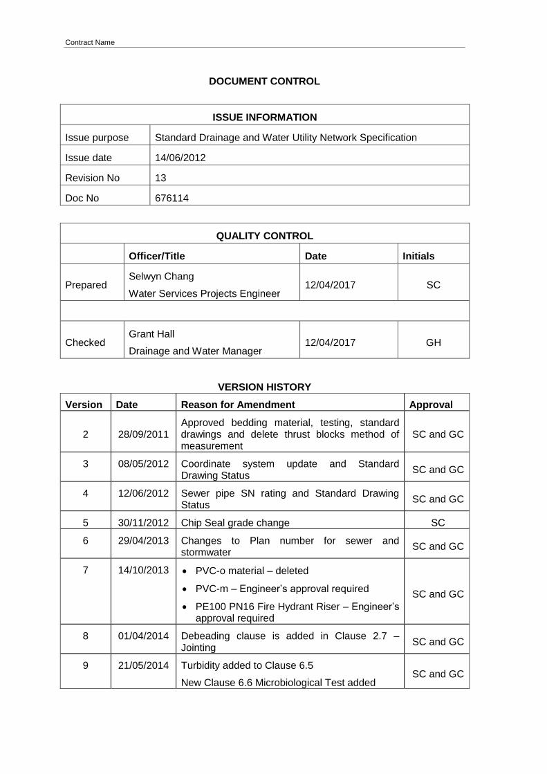
DOCUMENT CONTROL
ISSUE INFORMATION
Issue purpose Standard Drainage and Water Utility Network Specification
Issue date 14/06/2012
Revision No 13
Doc No 676114
QUALITY CONTROL
Officer/Title Date Initials
Prepared Selwyn Chang
Water Services Projects Engineer 12/04/2017 SC
Checked Grant Hall
Drainage and Water Manager 12/04/2017 GH
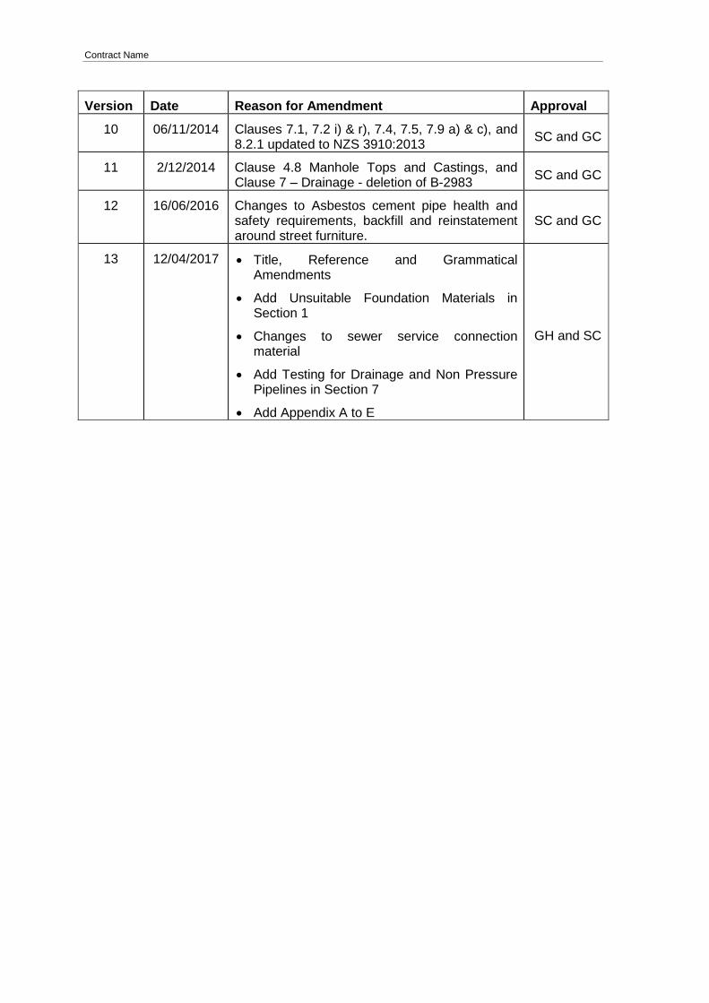
VERSION HISTORY
Version Date Reason for Amendment Approval
2 28/09/2011 Approved bedding material, testing, standard drawings and delete thrust blocks method of measurement
SC and GC
3 08/05/2012 Coordinate system update and Standard Drawing Status
SC and GC
4 12/06/2012 Sewer pipe SN rating and Standard Drawing Status
SC and GC
5 30/11/2012 Chip Seal grade change SC
6 29/04/2013 Changes to Plan number for sewer and stormwater
SC and GC
7 14/10/2013 PVC-o material – deleted
PVC-m – Engineer’s approval required
PE100 PN16 Fire Hydrant Riser – Engineer’s approval required
SC and GC
8 01/04/2014 Debeading clause is added in Clause 2.7 – Jointing
SC and GC
9 21/05/2014 Turbidity added to Clause 6.5
New Clause 6.6 Microbiological Test added SC and GC
Contract Name
Version Date Reason for Amendment Approval
10 06/11/2014 Clauses 7.1, 7.2 i) & r), 7.4, 7.5, 7.9 a) & c), and 8.2.1 updated to NZS 3910:2013
SC and GC
11 2/12/2014 Clause 4.8 Manhole Tops and Castings, and Clause 7 – Drainage - deletion of B-2983
SC and GC
12 16/06/2016 Changes to Asbestos cement pipe health and safety requirements, backfill and reinstatement around street furniture.
SC and GC
13 12/04/2017 Title, Reference and Grammatical Amendments
Add Unsuitable Foundation Materials in Section 1
Changes to sewer service connection material
Add Testing for Drainage and Non Pressure Pipelines in Section 7
Add Appendix A to E
GH and SC
Contract Name
1. DRAINAGE AND WATER SPECIFICATION - EXCAVATION
1.1 EXCAVATIONS
Excavation shall be to such depths and alignments as required to permit the proper execution of the works.
Trenches shall be excavated in straight lines, or in even curves between bends and fittings and the trench bottom shall be trimmed to an even level and grade, free from soft spots, rocks, loose clay and other debris before pipe laying or fitting work is commenced.
At no stage shall the length of open excavation exceed 100 metres. The Contractor shall determine the extent of the soil saturation at the time of excavation and take all practical measures to prevent differential settlement.
If the Contractor takes out any material to a greater depth than shown on the drawings or specification without the instruction of the Engineer, the extra depth shall be filled with approved fill material compacted as specified in this specification at the contractor’s expenses.
Where the excavation interrupts vehicular or pedestrian access to private property the Contractor shall reinstate access as soon as practicable. Access must be made available outside normal working hours by providing bridging strong enough to take the usual loading, or to the satisfaction of the Engineer.
1.2 BRACING OF EXCAVATIONS
Where sheet piling, shoring, sheeting, bracing or other supports are necessary they shall be supplied, placed, maintained and removed by the Contractor. The Contractor is to make allowance within scheduled rates for any bracing required.
This type of support used shall be suitable to the type of material encountered and shall be removed from the excavation before or while backfilling proceeds unless otherwise directed by the Engineer.
1.3 CONTROL OF WATER
The Contractor shall keep the excavation free from water during construction and shall dispose of the water without causing nuisance or injury to public or private property. The Contractor shall supply, install, operate and maintain all pumping plant, subdrains, pipework and other equipment necessary for this purpose and shall have access to reasonable standby equipment in good working order. Temporary subdrains, sumps or wells will not be allowed under the permanent work except where in the opinion of the Engineer, such are required to keep the excavation clear of water. The Contractor shall ensure that the flow of water in trenches does not injure or remove the cement or aggregate of any concrete that has not set. The permission of the Engineer must be obtained before any water is discharged into existing drains.
1.4 DEWATERING
The Contractor shall state at the commencement of the Contract the method to be used for controlling water in trenches or dewatering and this shall be to the written approval of the Engineer. This method statement shall include:
A reason why the proposed dewatering system has been chosen.
Proposed location and details of any well points.
Details of back-up power supplies in case there is a power failure.
Contract Name
Details of how noise restrictions will be met.
The Contractor shall ensure that the trench floor is adequately drained such that ponding or flooding does not occur. Where possible, trenches shall be completely dewatered before any bedding is placed or any pipes are laid. The trench (including the bedding) shall be kept free from water until the pipeline has been constructed according to the Specification and the trench backfilled.
Where this is not possible, or where the Contractor elects and the Engineer approves in writing, the Contractor may work in a trench with some water. The use of permeable material in the trench as a means of controlling the water could allow migration of material from the trench floor or wall into the bedding. Where this is a possibility, the material shall be enclosed within a geotextile that ensures that this migration cannot occur.
The Contractor is reminded that ground settlement may take place under buildings if water tables are lowered and maintained at a low level for prolonged periods. The Contractor shall make good any damage or settlement caused to buildings, roads, pipelines or other structures. This shall not constitute a Variation.
The Contractor shall make adequate provision to trap silt, sand and other material in suspension before discharging water into existing drainage channels. Water shall be discharged in a manner that prevents damage to the existing drainage system or landforms. The Contractor shall remove any material deposited in these existing sewers or drainage channels. This shall not constitute a Variation.
1.5 CONTINUOUS WELLPOINTING
Continuous wellpointing shall only be used where, in the opinion of the Engineer, the trench cannot be satisfactorily dewatered by the use of sumps and dewatering pumps. The Engineer’s approval must be given in writing before the Contractor may use continuous wellpointing.
Where wellpointing plant is to be used in a residential area it shall be sufficiently silenced to meet the noise control requirements given in the Preliminary and General section of the Specification.
The Contractor shall supply, install, operate, maintain and remove such approved wellpointing equipment.
1.6 DISCHARGE OF WATER
If the discharge of de-watering water requires a resource consent, it shall be the Contractor’s responsibility to obtain this consent and to comply with it. The cost of obtaining the consent and complying with it shall be at the Contractor’s expense.
1.7 UNSUITABLE FOUNDATION MATERIAL
Should the ground be unsuitable for the drain foundations the Contractor shall excavate to a solid foundation or to such a depth as approved by the Engineer.
The foundation shall then be rebuilt to correct levels with approved foundation materials which shall consist of approved compacted river run metal not exceeding 65mm maximum size. The backfilling material shall be spread in loose layers not exceeding 200mm and then compacted using approved compaction equipment as per this specification.
Contract Name
1.8 EXCAVATED MATERIAL
All excavated material shall be disposed of by the Contractor and any costs associated with the disposal shall be paid for by the Contractor.
1.9 ACCESS
The Contractor shall be responsible for maintaining private access to all properties at all times unless the Engineer approves otherwise. Night time bridging of trenches or alternate access may have to be arranged.
1.10 MATERIAL SPILLED ONTO ROAD
The Contractor shall take care to ensure that no material (liquid or solid) is spilled onto the road, especially away from the immediate working area. If any material (liquid or solid) should spill onto the road, it shall be removed immediately at the contractor’s expense.
1.11 SAW CUTTING
Where excavation is to be carried out in the roadway or footpath the Contractor shall arrange to have the trench saw cut to prevent sections of the roadway or footpath outside the trench limits lifting during excavation.
Should damage occur beyond the saw cut section after excavation, pipelaying and back-filling the Contractor shall recut the damaged sections and excavate those areas to allow for 150mm of compacted AP 40 as specified herein.
1.12 ROCK EXCAVATION
Rock shall be defined as inorganic material that cannot be excavated without the aid of explosives, drilling or rock breaking equipment. Isolated boulders, which cannot be excavated without the aid of explosives, drilling or rock breaking equipment, shall be included in this definition.
Should it be necessary to excavate rock, payment will only be on the basis of measurements taken by the Engineer, before the material is excavated. The Contractor shall remove the overburden for a reasonable length before excavating the rock and notify the Engineer as soon as possible so that the volume of rock may be determined. The maximum widths allowed for payment will be the nominal pipe diameter plus 600mm with a minimum width of 900mm.
Explosives shall not be used unless expressly approved in writing by the Engineer. This approval shall be dependent on the following conditions being met:
Explosives and detonators shall be stored, handled and controlled in accordance with statutory requirements and Timaru District Council Bylaws.
Any damage caused through blasting operations shall be made good at the Contractors expense.
The time at which shots are to be fired shall require the Engineer’s approval and he shall be notified in writing 24 hours in advance of firing. Evidence must be produced at that time by the Contractor to show that he is complying with Statutes and Regulations.
Explosives shall be used only in moderate charges.
Every charge and all ground that might be shattered shall be adequately covered to prevent fragments flying.
Contract Name
All householders and the general public in the danger area shall be warned and kept
from any risk.
Traffic in the danger area shall be stopped, or diverted, while there is danger from firing operation.
Explosives shall be used only under the control of a competent person who is fully qualified under the relevant Regulations.
1.13 TEST HOLES
It shall be the responsibility of the Contractor to ascertain for himself the nature of the ground in which it is proposed to excavate.
The Council accepts no responsibility for the interpretation of ground test information.
1.14 PROTECTION OF EXCAVATIONS
There shall be sufficient safety fencing to completely surround each excavation. During periods of non attendance by the Contractor, this safety fencing shall be secured together.
Safety fences shall be designed to:
Have secure supportive top and bottom rail.
Have the top rail a minimum of 1.0m above ground level.
Have the bottom rail a maximum of 100mm above ground level.
Be continuous, joined and secured around the hazard.
Barricades, cones, plastic mesh netting (not supported by a solid frame) and hurdles are not sufficient to adequately protect road users and pedestrians from excavations.
Small excavations may be entirely protected by the use of adequate crossing boards where this is appropriate. Special care shall be taken to ensure that this type of protection does not present a hazard to pedestrians.

Contract Name
2. DRAINAGE AND WATER SPECIFICATION – PIPELAYING AND BEDDING
2.1 SCOPE
This specification includes the supply (where required) and installation of all necessary pipework to complete the work as shown on the drawings.
2.2 TYPES OF PIPES AND FITTINGS
The approved materials for use in this contract are detailed in this contract document and on the contract drawings.
2.3 BEDDING
Unless otherwise indicated on the drawings or directed by the Engineer, all pipes shall be laid on a minimum 100mm bed of compactable AP20 or suitable alternative material as approved by the Engineer. The bed shall be compacted into place using mechanical compaction methods and meeting AS/NZS2566 compaction requirements. Socket holes or collar holes shall be excavated in the bedding material so that the pipe, when laid, shall have a uniform bearing under the full length of the barrel of the pipe.
A minimum of 150mm of compactable AP20 material shall be installed in place above the crown of pipe.
No bedding material shall be sourced from beach material containing saline properties.
No bedding material shall be placed so as to interfere with the operation of any valve or stop tap.
When concrete bedding is requested to be used by the Engineer for use with a flexibility jointed pipe, the bedding shall be interrupted at each joint by a spacer of softboard, or by some other method approved by the Engineer, to ensure that the flexibility of the joint is maintained.
Bricks or other hard material shall not be placed under pipes as temporary supports. See bedding drawings.
2.4 SIDE SUPPORT AND OVERLAY
Pipes shall be backfilled to a level of 150mm above the top of the crown of the pipe and shall consist of the same material specified for pipe bedding as detailed in this specification. The side support and overlay material shall be compacted in layers appropriate to meet AS/NZS2566 minimum compaction requirements. Material shall be placed in a manner to ensure:
Uniform distribution and compaction of material
Pipe distortion is minimised
Any coatings not damaged
Specified alignment and grade is maintained
Side support material shall be brought up evenly on each side of the pipe
2.5 COMPACTION
Backfill material placed to a level 150mm above the top of the pipes shall be compacted by approved mechanical method.
Contract Name
Compaction shall be by an approved mechanical compaction vibrating plate of a maximum size determined by the work, so as to obtain maximum density at optimum moisture content. It may be necessary for water to be added to the material to aid compaction to achieve the maximum density.
If material which has already been placed in the excavation becomes wet and or unsuitable for compaction then the material shall be excavated to waste and replaced with other approved backfill material.
2.6 TESTING OF COMPACTION FOR BEDDING MATERIAL
The Contractor shall test the compaction around the pipe bedding, side support and overlay to verify adequacy of compaction. Compaction testing methodology shall be approved using compaction trials prior to contract commencing. The Principal may accept the compaction trials from a Nuclear Density Meter (NDM) to be retested with a Clegg hammer and apply an equivalent calculation of the use during construction. This methodology will require engineer’s approval prior to construction commencing.
Testing during construction shall be carried out every 100m or otherwise specified by the Engineer. The results of these tests shall be provided to the Engineer.
Trenches tested with a reading below those approved above will require re-compaction or excavation and new compaction, as required, to achieve adequate results.
Other methods may be used by the Engineer to confirm adequacy of compaction. Density measurements may be taken and these require dry density values to be >95% of maximum dry density of backfill material.
2.7 LINE AND GRADE
Each separate pipe shall be individually set true to line and grade with a continuously supported barrel and each joint shall be completed before another pipe is laid. Pipes shall be laid on straight lines between changes of line and or grade.
For trenchless installations the pipe alignment shall not vary by more than half a pipe diameter.
Immediately before laying, each pipe shall be inspected for defects and any defective pipe rejected.
The minimum cover to all new watermains and ridermain shall be 800mm in berms and footpaths and 1000mm in road carriageway, or that approved in writing by the Engineer prior to construction.
2.8 JOINTING
Jointing shall be strictly in accordance with the manufactures recommendations. No jointing will be permitted under water unless expressly approved in writing by the Engineer.
Butt fusion welding shall be carried out by personnel who have satisfactorily completed Industry Approved Training Courses on Welding of Polyethylene Pipe Systems. Electrofusion and Extrusion Welding Certification of such qualification will be produced on request by the Engineer.
All sewer PE pipe jointing will need to be debeaded as much as possible without compromising the pipe structure integrity.
Spigots, sockets, rubber rings, sleeve couplings etc. shall be thoroughly cleaned before jointing.

Contract Name
The jointing of new pipe to old shall be carried out using a repair coupling complying with the joint performance requirements of BS EN 295: 1991. The repair coupling shall comprise of moulded synthetic elastomeric sleeves together with stainless steel clamping bands and shall also incorporate a stainless steel shear band thereby eliminating displaced pipes. Should the pipes being jointed be of different external diameter synthetic elastomer bushes sized correctly shall be used.
Where the pipe is jointed to the manhole, a stub pipe projecting no more than 100mm from the structure and flexibly jointed at the free end shall be used. Where relative settlement is likely between the structure and the pipe such as in soft ground conditions or otherwise directed by the Engineer, the pipe joined to the stub pipe shall be no longer than one metre and shall be flexibly jointed at both ends.
Under the Building Act 1991, mortar joints are not permitted except at the expressed direction and with the approval of the Engineer. When such joints are necessary the Engineer’s recommendations and directions are to be strictly adhered to. Each joint shall be cleaned out and finished flush with the bore before the next pipe is laid.
2.9 CUTTING OF PIPES
Where cutting of pipes is required, a pipe cutter, or appropriate saw should be used. The cut end shall be neat and regular. Pipes which are cracked behind the cut shall not be used but the damaged section may be removed and the remainder used. Where a cut pipe is to be joined with a rubber ring or sleeve the sharp cut edge shall be removed, using the pipe manufacturers approved trimming tool.
Cut faces of pipes exposing reinforcing steel are to be placed 30mm back from the internal faces of all manholes and the remaining 30mm is to be finished with concrete by hand. This practice is to ensure that all reinforcement steel has adequate cover.
When cutting Asbestos Cement pipes, the Contractor and contractor’s employees shall at all times comply with the requirements of the Health and Safety at Work (Asbestos) Regulations 2016.
2.10 CLEANLINESS
All pipelines at all times during the work shall be kept clean and free of all dirt, rubbish and other debris.
At the completion of each day’s pipe laying, the ends of the pipe shall be covered to prevent the ingress of dirty water or debris.
Waterblasting mud from pipes after drilling to a collection point and removed from system.
2.11 TESTING
The pipeline will be inspected visually by the Engineer for line, grade, jointing and standard of workmanship prior to backfilling taking place. All testing procedures are to be in accordance with Section 7 in this specification.
2.12 EXISTING FLOWS
The Contractor may request residents contributing to a section of sewer to be reconstructed to minimise their discharge to the foul sewer during the rehabilitation process.
Any request to minimise their discharge to the foul sewer shall not exceed the hours of 9.00am to 5.00pm.
Contract Name
The installation of a by-pass system may be required. The Engineer shall approve any by-pass system prior to its installation. In any event where flows are temporarily disrupted by the work the Contractor shall monitor closely the system, affected and especially low connections. Construction shall be carried out with due consideration to the predicted weather forecast.
2.13 INSPECTIONS
The Contractor shall make provision for the Engineer to monitor the installation process at all times.
2.14 CCTV INSPECTION
Once complete the Contractor will arrange for the new sewer to be videoed using closed circuit television equipment with accordance to the New Zealand Pipe Inspection Manual. The film shall indicate clearly the running meterage and detailed pictures of each connection. The cost of the video will be borne by the Contractor.
2.15 DRAINAGE SERVICE CONNECTIONS
All sewer service connections and mains shall be uPVC or polyethylene (PE).
Stormwater connections and mains are to be uPVC, PE or RCRRJ for 225mm and above.
Connections of private drains shall be made in accordance to the “Cut-in a Y-Junction” method or approved by Engineer:
Cut-in a Y Junction Method:
1 A section of the existing drain no longer than is absolutely necessary shall be cut out to accommodate the new Y junction.
2 The length of this will depend on the material types involved and how they are to be joined together.
3 A factory made Y junction, shall be laid into the ensuing space, supported on granular bedding of the required depth.
4 The inserted section shall be spliced to the existing main using slip collars, gibault joints, pipeline adapter, etc. to the satisfaction of the Council’s Representative.
5 Neoprene sleeve joiners will only be allowed where the outside diameter of the pipes remains the same, and then only if they have a central stainless steel sheer band.
6 The completed connection shall be covered to a height of 150mm above the pipe with granular bedding material.
2.16 WATER SERVICE CONNECTIONS
Water services shall be laid in accordance with standard Plan 5304 for urban and the rural schemes
20mm Diameter or greater HDPE, MDPE water pipes shall not require relaying unless a larger size service is specified.
All 12mm Diameter and all galvanised pipe shall be re-laid. Inspection shall be carried out by the Engineer to confirm the total quantity of relay required.
Services that cross the centreline of the road shall be installed where practical by trenchless methods for the width of the roadway from the watermain to the back of any kerb and channel or equivalent water table. Water Services shall be installed hard against the boundaries and not in traffic areas or driveways.
Contract Name
Toby boxes in accordance with Plan 5304 Sheet 4 shall be installed 300mm from the property boundary fence unless directed to install elsewhere by the Engineer.
For rural scheme all pipe work at tank is to be replaced with DN25 PN16 PE100 and is to have frost protection where exposed. Float valves are to be replaced and are to be PN16 rated. Flow restrictors shall be replaced.
2.17 TEES, SLUICE VALVES AND FIRE HYDRANTS
Tees, sluice valves and fire hydrants shall be installed as per the plans with the spindles truly vertical. Where practical all tees, valves etc. shall be preassembled and lowered into the trench. Only chains or webbed lifting strops of sound condition and adequate strength shall be used in the lifting of valves etc.
The anchoring point for such lifting shall be purpose built and entirely adequate. Special care shall be taken to ensure that the protective coating on the valves is not damaged. All manufacturers’ recommendations shall be followed with regard to handling, storage and installation. Galvanised washers shall be installed between the valve surface and the nut or bolt head. The top of valve stem caps shall be set within the dimensions shown on standard Plan 5304 Sheet 2 below final ground level. All stem risers shall be of an approved type with a circular stem and with standard connectors. The valve stem cap and any risers shall be tapped into position with a soft faced hammer and the attachment securely tightened.
All valves 50mm or larger shall be sluice valves unless approved otherwise by the Engineer.
Each sluice valve is to have a concrete anchor block attached and be installed in accordance with standard Plan 5304 Sheet 2 and AS/NZS 4404. The thrust block of an adjacent angle or tee etc. may be utilised where appropriate. The size of the anchor block and tie downs shall be approved by the Engineer prior to construction.
The relevant standard for fire hydrants marking is NZS 4501:1972. The Contractor is to make allowance within scheduled rates for new fire markings.
2.18 SURFACE COVERS
Toby boxes, water meter boxes, valve boxes and fire hydrant boxes shall be brought to level using suitably approved riser blocks. A suitably sized PVC pipe shall be inserted down the inside of the box to the valve riser on mainline valves.
Excavations for surface covers shall have even clean edges.
All boxes shall be placed centrally over the item to be accessed, such that access and operation is unimpaired.

Contract Name
3. DRAINAGE AND WATER SPECIFICATION - POLYETHYLENE PIPELINES
3.1 EXTENT OF WORK
This specification includes the supply, installation and testing of polyethylene pipelines, for both gravity and pressure applications, to be read in conjunction with Section 7.
3.2 MATERIALS
3.2.1 Polyethylene Pipes
Polyethylene pipes on this project are used for transfer of water under pressure conditions.
For pressure applications, the pipeline rating shall be as stated on the drawings, or a minimum of PN12.5.
Polyethylene pipes shall be manufactured in accordance with AS/NZS 4130 Series 1, using PE100 material conforming with AS/NZS 4131. Note that material to PE100 – 165 AS/NZS 4131 is not acceptable. Certification of compliance to AS/NZS 4131 is to be provided for all pipe material used. The pipe manufacturer shall provide a certificate of compliance to AS/NZS 4130 for all pipes supplied. (All pipes shall be uniquely identified in order to check pipes as-installed against the certificates.)
Pipe handling and storage shall conform to the requirements of AS/NZS 2033 and AS/NZS 2566.2. Storage of the pipe shall be the Contractor’s responsibility. Any damage to a pipe exceeding 10% of the wall thickness, or any sharp notches, shall be cause for rejection of the pipe section so damaged. Should a pipe show evidence of kinking, that section of pipe shall be rejected and replaced, and the rejected section removed from the Site.
Polyethylene pipes shall be installed in accordance with AS/NZS 2566 and the pipe supplier’s recommendations. To avoid damage to the PE pipe during installation, all necessary methods of protection shall be employed by the Contractor.
3.2.2 Polyethylene Pipe Fittings
All bends, tees, reducers, stub flanges and other pipe fittings shall be fully compatible with the pipeline materials. All polyethylene joints, bends, and fittings shall be moulded from PE100 material complying with AS/NZS 4131.
Where available, fittings shall:
be moulded fittings;
comply with AS/NZS 4129, and Certificates of Compliance to AS/NZS 4129 shall be supplied; and
be constructed solely from PE material.
3.2.3 Jointing Systems
The jointing system for PE pipes shall be by integral electrofusion joints or butt welding. The method of jointing a fitting to pipe shall ensure stress gradients across the joint resulting from differing wall thickness are within acceptable limits. Excepting where identified on the drawings, or with the written approval of the Engineer, mechanically jointed connections shall not be used, excepting for PE stub flange adapters where required at connections with valves.
Contract Name
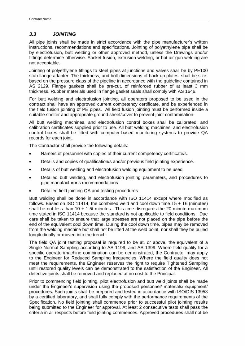
3.3 JOINTING
All pipe joints shall be made in strict accordance with the pipe manufacturer’s written instructions, recommendations and specifications. Jointing of polyethylene pipe shall be by electrofusion, butt welding or other approved method, unless the Drawings and/or fittings determine otherwise. Socket fusion, extrusion welding, or hot air gun welding are not acceptable.
Jointing of polyethylene fittings to steel pipes at junctions and valves shall be by PE100 stub flange adapter. The thickness, and bolt dimensions of back up plates, shall be size-based on the pressure class of the pipeline in accordance with the guideline contained in AS 2129. Flange gaskets shall be pre-cut, of reinforced rubber of at least 3 mm thickness. Rubber materials used in flange gasket seals shall comply with AS 1646.
For butt welding and electrofusion jointing, all operators proposed to be used in the contract shall have an approved current competency certificate, and be experienced in the field fusion jointing of PE pipes. All field fusion jointing must be performed inside a suitable shelter and appropriate ground sheet/cover to prevent joint contamination.
All butt welding machines, and electrofusion control boxes shall be calibrated, and calibration certificates supplied prior to use. All butt welding machines, and electrofusion control boxes shall be fitted with computer-based monitoring systems to provide QA records for each joint.
The Contractor shall provide the following details:
Name/s of personnel with copies of their current competency certificate/s.
Details and copies of qualification/s and/or previous field jointing experience.
Details of butt welding and electrofusion welding equipment to be used.
Detailed butt welding, and electrofusion jointing parameters, and procedures to pipe manufacturer’s recommendations.
Detailed field jointing QA and testing procedures
Butt welding shall be done in accordance with ISO 11414 except where modified as follows. Based on ISO 11414, the combined weld and cool down time T5 + T6 (minutes) shall be not less than 10 + 1.5t minutes. This time disregards the 20 minute maximum time stated in ISO 11414 because the standard is not applicable to field conditions. Due care shall be taken to ensure that large stresses are not placed on the pipe before the end of the equivalent cool down time. During the cool down time, pipes may be removed from the welding machine but shall not be lifted at the weld point, nor shall they be pulled longitudinally or moved into the trench.
The field QA joint testing proposal is required to be at, or above, the equivalent of a Single Normal Sampling according to AS 1199, and AS 1399. Where field quality for a specific operator/machine combination can be demonstrated, the Contractor may apply to the Engineer for Reduced Sampling frequencies. Where the field quality does not meet the requirements, the Engineer reserves the right to require Tightened Sampling until restored quality levels can be demonstrated to the satisfaction of the Engineer. All defective joints shall be removed and replaced at no cost to the Principal.
Prior to commencing field jointing, pilot electrofusion and butt weld joints shall be made under the Engineer’s supervision using the proposed personnel/ materials/ equipment/ procedures. Such joints shall be prepared and tested in accordance with ISO/DIS 13953 by a certified laboratory, and shall fully comply with the performance requirements of the Specification. No field jointing shall commence prior to successful pilot jointing results being submitted to the Engineer for approval. At least 2 consecutive tests shall pass the criteria in all respects before field jointing commences. Approved procedures shall not be
Contract Name
changed in the field prior to written approval by the Engineer. Test welding shall be repeated if there is a change of weld machine or its operator.
Butt weld joints are required to have a weld strength factor of not less than 90% of the parent pipe’s ultimate tensile strength, with weld rupture to be ductile in performance, and contain no contamination/defects when tested using Compact Tensile Fracture specimens. When tested with full wall sections in a 3 point flexural beam test, the welds shall not tear/rupture/fracture when stressed to the Yield Stress of the PE100 material. Test specimens are required to be taken around the pipe circumference and all samples shall exhibit similar behaviour. Brittle welds shall be rejected. Weld beads shall be fully formed, and within approved weld bead sizes. Welds exhibiting pitting/voiding on the weld bead surfaces shall be rejected. Removal of internal and external weld beads is not required.
Electrofusion joints are required to be tested in accordance with PIPA. Electrofusion fittings are required to have melt indicators. Joints exhibiting PE melt flow at the fitting edges, or non-risen melt indicators, shall be rejected.
The Contractor shall have in place a Quality Assurance procedure for all aspects of managing the pipe laying process including manufacture, handling, jointing, laying and testing. All joints are required to be numbered and their location marked on construction record plans. Full records of all field joints including parameters achieved, personnel, machines etc. used shall be maintained and submitted to the Engineer. Testing shall be performed on the first field joint made for each pipe diameter for butt weld, and electrofusion joint type. Up to 5% of pipe line field welds may be randomly selected for testing weld quality. The Contractor shall allow for all costs associated with cutting out, reinstating, testing and reporting.
All defective work shall be removed from Site and made good.
The procedures shall be regularly audited on a monthly basis by a suitably qualified and recognised authority in this field who shall report any deficiencies in welding procedure directly to the Engineer. That person or organisation shall be nominated in the quotation.
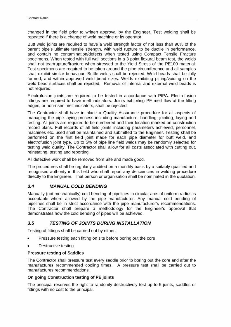
3.4 MANUAL COLD BENDING
Manually (not mechanically) cold bending of pipelines in circular arcs of uniform radius is acceptable where allowed by the pipe manufacturer. Any manual cold bending of pipelines shall be in strict accordance with the pipe manufacturer’s recommendations. The Contractor shall prepare a methodology for the Engineer’s approval that demonstrates how the cold bending of pipes will be achieved.
3.5 TESTING OF JOINTS DURING INSTALLATION
Testing of fittings shall be carried out by either:
Pressure testing each fitting on site before boring out the core
Destructive testing
Pressure testing of Saddles
The Contractor shall pressure test every saddle prior to boring out the core and after the manufactures recommended cooling times. A pressure test shall be carried out to manufactures recommendations.
On going Construction testing of PE joints
The principal reserves the right to randomly destructively test up to 5 joints, saddles or fittings with no cost to the principal.
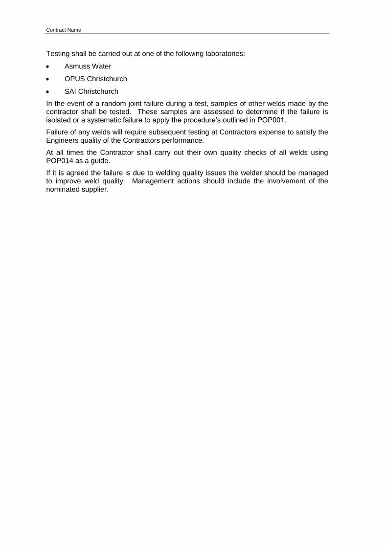
Contract Name
Testing shall be carried out at one of the following laboratories:
Asmuss Water
OPUS Christchurch
SAI Christchurch
In the event of a random joint failure during a test, samples of other welds made by the contractor shall be tested. These samples are assessed to determine if the failure is isolated or a systematic failure to apply the procedure’s outlined in POP001.
Failure of any welds will require subsequent testing at Contractors expense to satisfy the Engineers quality of the Contractors performance.
At all times the Contractor shall carry out their own quality checks of all welds using POP014 as a guide.
If it is agreed the failure is due to welding quality issues the welder should be managed to improve weld quality. Management actions should include the involvement of the nominated supplier.
Contract Name
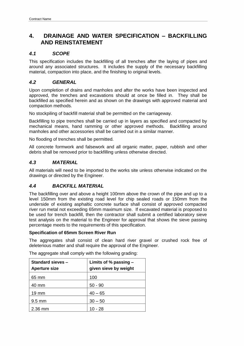
4. DRAINAGE AND WATER SPECIFICATION – BACKFILLING AND REINSTATEMENT
4.1 SCOPE
This specification includes the backfilling of all trenches after the laying of pipes and around any associated structures. It includes the supply of the necessary backfilling material, compaction into place, and the finishing to original levels.
4.2 GENERAL
Upon completion of drains and manholes and after the works have been inspected and approved, the trenches and excavations should at once be filled in. They shall be backfilled as specified herein and as shown on the drawings with approved material and compaction methods.
No stockpiling of backfill material shall be permitted on the carriageway.
Backfilling to pipe trenches shall be carried up in layers as specified and compacted by mechanical means, hand ramming or other approved methods. Backfilling around manholes and other accessories shall be carried out in a similar manner.
No flooding of trenches shall be permitted.
All concrete formwork and falsework and all organic matter, paper, rubbish and other debris shall be removed prior to backfilling unless otherwise directed.
4.3 MATERIAL
All materials will need to be imported to the works site unless otherwise indicated on the drawings or directed by the Engineer.
4.4 BACKFILL MATERIAL
The backfilling over and above a height 100mm above the crown of the pipe and up to a level 150mm from the existing road level for chip sealed roads or 150mm from the underside of existing asphaltic concrete surface shall consist of approved compacted river run metal not exceeding 65mm maximum size. If excavated material is proposed to be used for trench backfill, then the contractor shall submit a certified laboratory sieve test analysis on the material to the Engineer for approval that shows the sieve passing percentage meets to the requirements of this specification.
Specification of 65mm Screen River Run
The aggregates shall consist of clean hard river gravel or crushed rock free of deleterious matter and shall require the approval of the Engineer.
The aggregate shall comply with the following grading:
Standard sieves –
Aperture size
Limits of % passing –
given sieve by weight
65 mm 100
40 mm 50 - 90
19 mm 40 – 65
9.5 mm 30 – 50
2.36 mm 10 - 28
Contract Name
Standard sieves –
Aperture size
Limits of % passing –
given sieve by weight
0.0425 mm 0
0.075mm 0
4.4.1 TNZ M/4 AP 40
In carriageways and footpaths the remaining 150mm in both road surface conditions shall be backfilled with approved compacted base course to Transit New Zealand M4/AP 40 specification making allowance for thickness of reinstatement to take place.
4.4.2 CLAY BACKFILL
In private property, off roadways, backfill over and above a height of 100mm above the crown of the pipes shall consists of good quality excavated material to a level 300mm below the finished surface.
4.4.3 TOP SOIL
In lawns or gardens the remaining 150mm shall be backfilled with clean, screened topsoil free of all stones and other foreign matter, compacted and left ready for sowing in the case of lawns.
All lawn and garden areas are to be returned to their original levels and any vehicle marks in lawn areas are to be reinstated back to original levels.
4.5 COMPACTION
Backfill material placed to a level 300mm above the top of the pipes shall be compacted by hand ramming or an approved mechanical method.
From 300mm above the top of the pipes the backfill material shall be placed and compacted in layers not exceeding 200mm in depth.
Compaction shall be by an approved mechanical rammer, vibrating plate or vibrating roller of a maximum size determined by the work, so as to obtain maximum density at optimum moisture content. It may be necessary for water to be added to the material to aid compaction to achieve the maximum density.
If material which has already been placed in the excavation becomes wet and or unsuitable for compaction then the material shall be excavated to waste and replaced with other approved backfill material.
4.6 TESTING OF COMPACTION
The Contractor shall test the compaction of the backfill in the trenches to verify adequacy of compaction. Compaction testing methodology shall be approved using compaction trials prior to contract commencing. The Principal may accept the compaction trials from a Nuclear Density Meter (NDM) to be retested with a Clegg hammer and apply an equivalent calculation of the use during construction. This methodology will require engineer’s approval prior to construction commencing.
Compaction Testing shall be carried out by as per Section 5.5.5 of the National Code of Practice for Utility Operators’ Access to Transport Corridors.
Contract Name
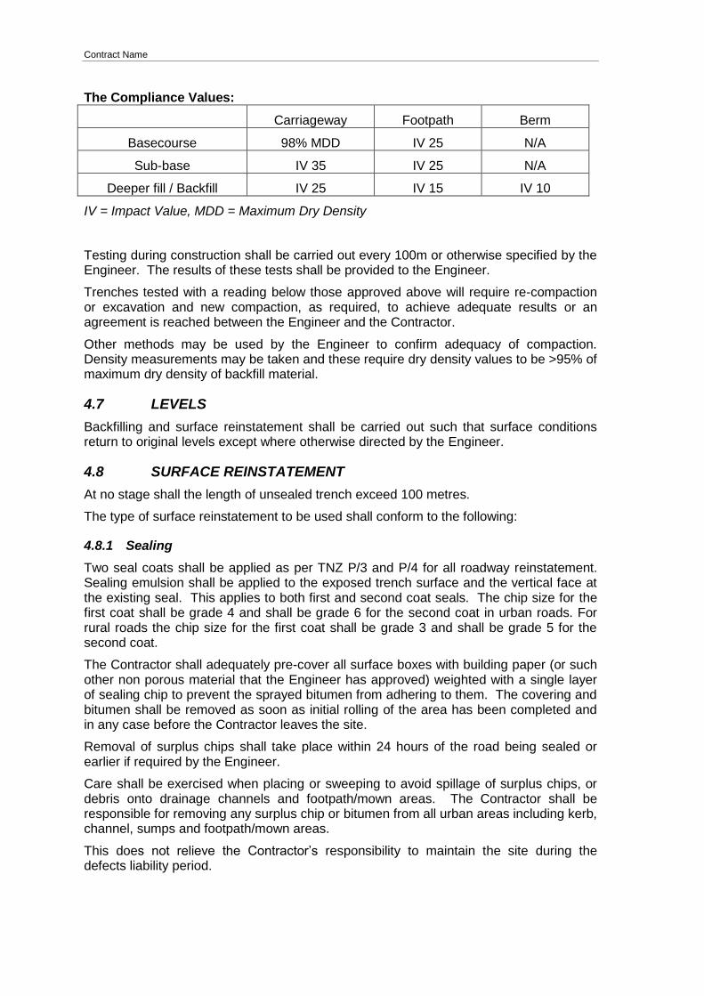
The Compliance Values:
Carriageway Footpath Berm
Basecourse 98% MDD IV 25 N/A
Sub-base IV 35 IV 25 N/A
Deeper fill / Backfill IV 25 IV 15 IV 10
IV = Impact Value, MDD = Maximum Dry Density
Testing during construction shall be carried out every 100m or otherwise specified by the Engineer. The results of these tests shall be provided to the Engineer.
Trenches tested with a reading below those approved above will require re-compaction or excavation and new compaction, as required, to achieve adequate results or an agreement is reached between the Engineer and the Contractor.
Other methods may be used by the Engineer to confirm adequacy of compaction. Density measurements may be taken and these require dry density values to be >95% of maximum dry density of backfill material.
4.7 LEVELS
Backfilling and surface reinstatement shall be carried out such that surface conditions return to original levels except where otherwise directed by the Engineer.
4.8 SURFACE REINSTATEMENT
At no stage shall the length of unsealed trench exceed 100 metres.
The type of surface reinstatement to be used shall conform to the following:
4.8.1 Sealing
Two seal coats shall be applied as per TNZ P/3 and P/4 for all roadway reinstatement. Sealing emulsion shall be applied to the exposed trench surface and the vertical face at the existing seal. This applies to both first and second coat seals. The chip size for the first coat shall be grade 4 and shall be grade 6 for the second coat in urban roads. For rural roads the chip size for the first coat shall be grade 3 and shall be grade 5 for the second coat.
The Contractor shall adequately pre-cover all surface boxes with building paper (or such other non porous material that the Engineer has approved) weighted with a single layer of sealing chip to prevent the sprayed bitumen from adhering to them. The covering and bitumen shall be removed as soon as initial rolling of the area has been completed and in any case before the Contractor leaves the site.
Removal of surplus chips shall take place within 24 hours of the road being sealed or earlier if required by the Engineer.
Care shall be exercised when placing or sweeping to avoid spillage of surplus chips, or debris onto drainage channels and footpath/mown areas. The Contractor shall be responsible for removing any surplus chip or bitumen from all urban areas including kerb, channel, sumps and footpath/mown areas.
This does not relieve the Contractor’s responsibility to maintain the site during the defects liability period.

Contract Name
4.8.2 Asphaltic Concrete
Once the trenches have been backfilled as specified a waterproofing layer of either 180/200 penetration grade bitumen and Grade 4 chip or emulsion and chip shall be to the applied level of the underside and the vertical face of the existing asphaltic concrete mix. A cationic emulsion tack coat with a minimum bitumen content of 55% shall then be applied to the chip seal. The tack coat shall meet the requirements of TNZ M/1:1995. An asphaltic concrete mix shall then be used so that the surface condition returns to the original level except where otherwise directed by the Engineer.
The asphaltic concrete mix shall be mix number 10 from Table 1 TNZ M/10:1975 and shall conform to TNZ M/10:1975. The asphaltic concrete shall be laid to TNZ P/9:1975.
The Contractor shall price on the basis that the minimum thickness required for the asphaltic concrete layer is to be 40mm for roadways and 20mm for footpaths.
4.8.3 Lawns
Disturbed grassed areas shall be sown with a certified grass seed mixture containing 65% fine turf ryegrass; 35% fine fescues applied at 25gm/m2.
The seed shall be broadcast by hand, half in each direction at right angles, and the surface lightly raked and rolled. Water and keep moist throughout the growth phase until 20mm high and then as necessary.
The Contractor shall achieve 100% coverage of fine leafed grass, fee from broad-leafed weeds.
Plants and shrubs previously removed shall be carefully replaced in their original position. However if this position is over the new main the plant shall be placed not less than 500mm away from the centre line of the new main.
4.9 ROAD MARKING
The Contractor is to inform the Engineer within 24 hours of disturbing any existing road markings. It shall be the responsibility of the contractor to liaise with the Land Transport Unit of the Council to have these marks replaced once the road surface restatement has been completed.
4.10 ROAD FURNITURE
The Contractor shall exercise care when working near road furniture and shall ensure all furniture is visible by the end of each days work. Water valves and fire hydrants shall whenever possible remain serviceable throughout the works. On completion of surfacing the top of service covers shall be flush and uniform with the final surface level.
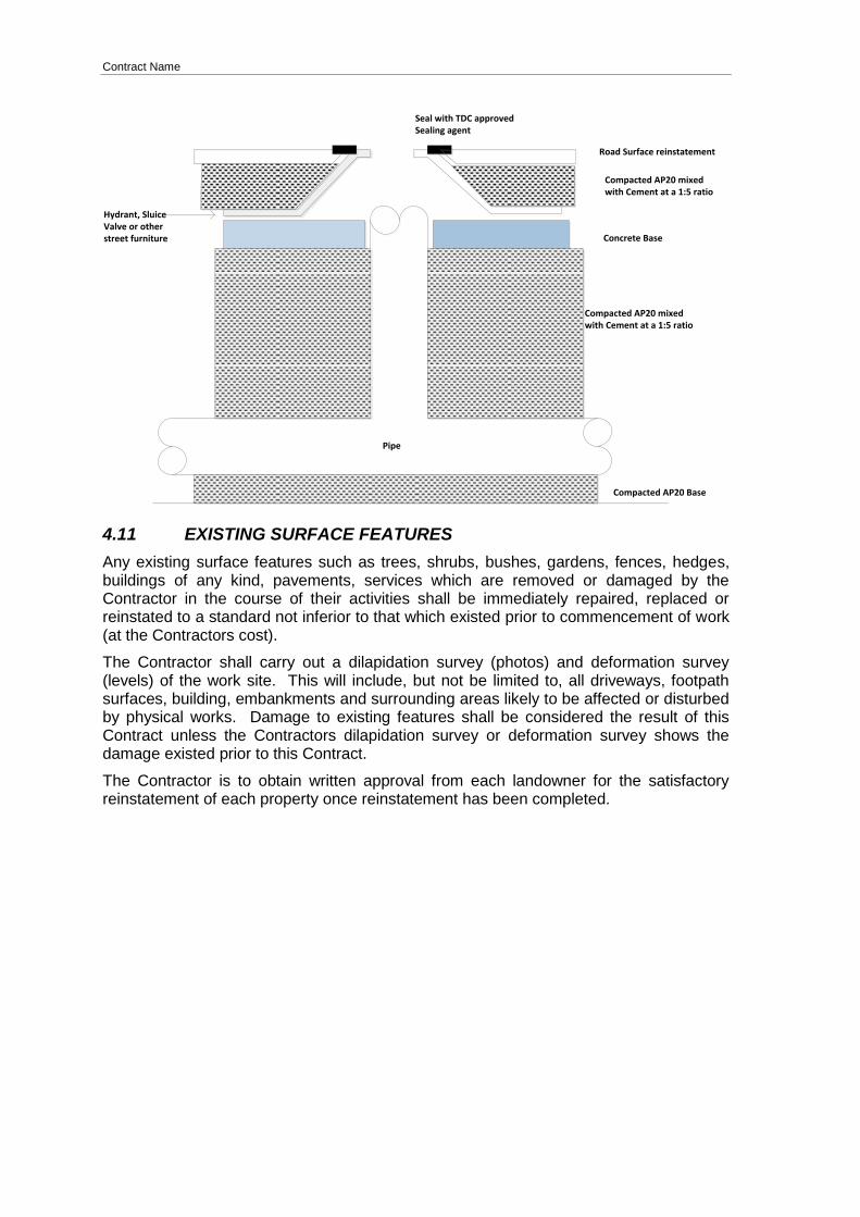
The Contractor shall backfill around the immediate area of the road furniture with compactable AP20, or equivalent, with a mixture of cement mixed at a ratio of 5%. Mixture shall be compacted in place, in 300mm increments, with a light sprinkle of water. Compaction shall meet AS/NZS2566 compaction requirements. Seal between Road furniture and road surface with TDC approved product (AC10 or equivalent for Asphalt Roads). Please refer to the diagram below.
All road furniture is to be cemented into position at the base using Rapid Cure Fosrock Render Roc Rapid with 50mm cover. A minimum of two concrete risers are to be used.
Contract Name
Compacted AP20 mixed with Cement at a 1:5 ratio
Compacted AP20 mixed with Cement at a 1:5 ratio
Road Surface reinstatement
Seal with TDC approved Sealing agent
Hydrant, Sluice Valve or other street furniture Concrete Base
Pipe
Compacted AP20 Base
4.11 EXISTING SURFACE FEATURES
Any existing surface features such as trees, shrubs, bushes, gardens, fences, hedges, buildings of any kind, pavements, services which are removed or damaged by the Contractor in the course of their activities shall be immediately repaired, replaced or reinstated to a standard not inferior to that which existed prior to commencement of work (at the Contractors cost).
The Contractor shall carry out a dilapidation survey (photos) and deformation survey (levels) of the work site. This will include, but not be limited to, all driveways, footpath surfaces, building, embankments and surrounding areas likely to be affected or disturbed by physical works. Damage to existing features shall be considered the result of this Contract unless the Contractors dilapidation survey or deformation survey shows the damage existed prior to this Contract.
The Contractor is to obtain written approval from each landowner for the satisfactory reinstatement of each property once reinstatement has been completed.

Contract Name
5. DRAINAGE SPECIFICATION – MANHOLE AND CONCRETE WORK
5.1 SCOPE
This specification includes the supply of materials, the construction of all manholes and other concrete work requested by the Engineer.
5.2 CONCRETE
All concrete shall comply with the requirements of NZS 3109:1987 “Specification for Concrete Construction” and shall have a minimum compressive strength of 40 MPa at 28 days.
Composition
The concrete shall be composed of ordinary Portland cement, natural or crushed aggregates, water and such admixtures as specified, proportioned and mixed as hereinafter specified and contain no deleterious materials.
The water used shall be the minimum to provide necessary workability, and for concrete to be placed in water retaining structures the water/cement ratio (by weight) shall not exceed 0.55 and the cement content shall not be less than 400kg Portland cement per cubic metre of concrete.
The maximum allowable slumps, determined in accordance with NZS 3112: 1986 “Methods of Test for Concrete” shall be as follows:
Vertical components 100mm
Horizontal components 80mm
Tolerances shall not exceed those specified in NZS 3109 Clause 9.3.3.
Construction Joints
Construction joints shall be kept to an absolute minimum and shall be located as far as is possible in the vicinity of point of contra flexure.
Proposed locations of construction joints and the method to be used shall be submitted to the Engineer and shall be approved by him prior to the setting up of formwork.
Subject to the approval of the Engineer to form construction joints by other methods, waterstops of an approved type and make shall be provided in all construction joints located within the water retaining structure.
If any construction joint is found to be not water tight the Contractor will waterproof the joint by a method approved by the Engineer.
Admixtures
Specific approval is required for the use of accelerators and retardants. Full detail of the material use and effects shall be provided at the time of application for use.
5.3 MANHOLES
Manholes may be either cast in-situ or precast.
5.3.1 Manholes - Cast In-situ
All manholes shall be of circular construction according to the dimensions and details as shown on Plan 5302.
Contract Name
Pipework, castings, bolts and other inserts shall be built in as work proceeds.
5.3.2 Manholes - Precast
Precast manholes shall be circular in construction and consist of the following components:
precast flanged bases;
risers;
lids; and
galvanised ladders.
All items shall be installed as per manufacturer’s instructions.
5.4 FORMWORK
Formwork shall be designed and constructed so that it can be removed without damage to the concrete. The Contractor shall ensure formwork is coated with a suitable solution to prevent the adherence of concrete.
All formwork shall be securely braced and supported to prevent any sagging, flotation or bulging during the deposition of concrete, and all joints shall be close enough to prevent undue leakage of liquid from the concrete. All forms shall be fixed to proper line and level and trued immediately before concrete is deposited.
5.5 PIPE CONNECTIONS TO MANHOLES
A flexible joint shall be provided within 100mm of the structure wall.
When using HDPE pipe a puddle flange suitable for butt fusion welding shall be used in joining the HDPE pipeline to the two existing manholes. A concrete corbel is to be used to secure the pipe to the existing manhole as per Plan 5302.
Where a pipeline joins onto an existing manhole, a hole of sufficient size to neatly accommodate the end pipe shall be made in the manhole wall without cracking or otherwise damaging the manhole structure and the necessary adjustments to the benching made with mortar consisting of one part of cement to one point five parts of sand by volume.
An external bondage joint of mortar or concrete of minimum thickness 75mm and incorporating the ends of wall reinforcements, if any, shall be made around the pipe, at the manhole wall.
5.6 LEVELS
In carriageways, driveways and paths manholes shall be constructed up to a level so that covers finish flush with, and at the camber of the surface of the carriageway etc.
In lawns and gardens manholes shall be constructed to such a level that the cover is horizontal and not less than 150mm nor more than 300mm below the final surface level unless otherwise directed by the Engineer.
5.7 STEP IRONS AND MANHOLE LADDERS
Cast in-situ manholes shall be constructed with galvanised step irons as shown on the drawings. Galvanised step irons should be evenly spaced at nominal 370mm vertical intervals. The lowest iron shall not be more than 450mm above the benching and the highest not more than 600mm below the top surface of the manhole cover.
Contract Name
Precast manholes shall have hot dipped galvanised ladders connected to the underside of the manhole lid. The ladder shall also be securely fixed to the manhole wall at the bottom of the ladder. The ladder shall be positioned so that it is above the upstream pipe.
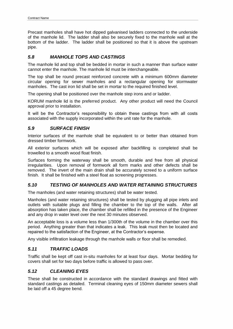
5.8 MANHOLE TOPS AND CASTINGS
The manhole lid and top shall be bedded in mortar in such a manner than surface water cannot enter the manhole. The manhole lid must be interchangeable.
The top shall be round precast reinforced concrete with a minimum 600mm diameter circular opening for sewer manholes and a rectangular opening for stormwater manholes. The cast iron lid shall be set in mortar to the required finished level.
The opening shall be positioned over the manhole step irons and or ladder.
KORUM manhole lid is the preferred product. Any other product will need the Council approval prior to installation.
It will be the Contractor’s responsibility to obtain these castings from with all costs associated with the supply incorporated within the unit rate for the manhole.
5.9 SURFACE FINISH
Interior surfaces of the manhole shall be equivalent to or better than obtained from dressed timber formwork.
All exterior surfaces which will be exposed after backfilling is completed shall be trowelled to a smooth wood float finish.
Surfaces forming the waterway shall be smooth, durable and free from all physical irregularities. Upon removal of formwork all form marks and other defects shall be removed. The invert of the main drain shall be accurately screed to a uniform surface finish. It shall be finished with a steel float as screening progresses.
5.10 TESTING OF MANHOLES AND WATER RETAINING STRUCTURES
The manholes (and water retaining structures) shall be water tested.
Manholes (and water retaining structures) shall be tested by plugging all pipe inlets and outlets with suitable plugs and filling the chamber to the top of the walls. After all absorption has taken place, the chamber shall be refilled in the presence of the Engineer and any drop in water level over the next 30 minutes observed.
An acceptable loss is a volume less than 1/300th of the volume in the chamber over this period. Anything greater than that indicates a leak. This leak must then be located and repaired to the satisfaction of the Engineer, at the Contractor’s expense.
Any visible infiltration leakage through the manhole walls or floor shall be remedied.
5.11 TRAFFIC LOADS
Traffic shall be kept off cast in-situ manholes for at least four days. Mortar bedding for covers shall set for two days before traffic is allowed to pass over.
5.12 CLEANING EYES
These shall be constructed in accordance with the standard drawings and fitted with standard castings as detailed. Terminal cleaning eyes of 150mm diameter sewers shall be laid off a 45 degree bend.

Contract Name
All pipework shall be 150mm diameter. Where located at a bend or change in grade, cleaning eyes shall be placed on the upstream side or as directed by the Engineer.

Contract Name
6. WATER SPECIFICATION – APPROVED MATERIALS AND MANUFACTURERS
6.1 SCOPE
This specification includes the materials approved by the Timaru District Council for use in the construction and maintenance of public water mains. Other materials shall not be used without the prior written approval of the Timaru District Council. Non complying materials may be required to be removed and replaced with complying materials at any time. Evidence to demonstrate that materials comply with these requirements shall be provided to the Timaru District Council on request.
This document must be read in conjunction with any relevant contract plans or specifications, which will overrule this document. Standard drawings will be overruled by this document. This document is subject to continual development and the Timaru District Council reserves the right to make changes without notice.
All materials supplied and used shall be new unless otherwise approved by the Timaru District Council.
A current licence mark certificate is to be supplied with all pipes, valves and fittings that are manufactured to a standard.
6.2 RURAL RETICULATION
Water Mains
A detectable location strip is to be installed with all non metallic water mains.
The warning location strip is to be coloured blue, to have a minimum width of 75mm and shall comply with AS/NZS2648.1:1995.
Approved warning location strips include-:
Boddingtons Waveby Detectable
Wavewater Detectable
Thortec Reinforced Detectable
Polyethylene (PE)
Polyethylene pipe shall conform to the following:
Pipe – In accordance with AS/NZS 4130:2003 Polyethylene (PE) pipes for Pressure Applications
Compound – PE 100 (MRS 10 MPa) in accordance with AS/NZS 4131:2003
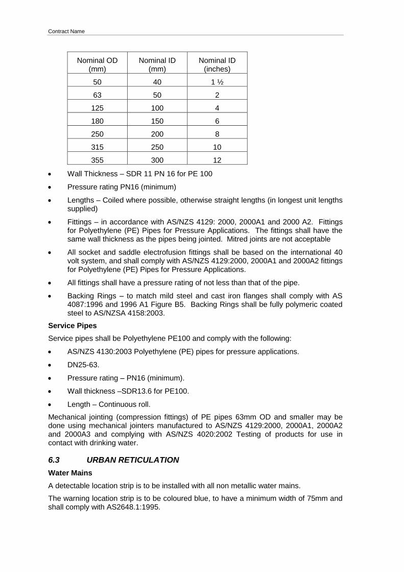
Dimensions – shall comply with Table 3 (Series 1 Pipes) of AS/NZS 4130:2003 Polyethylene (PE) Pipes for Pressure Applications.
Nominal dimensions
Nominal OD (mm)
Nominal ID (mm)
Nominal ID (inches)
25 20 ¾
32 25 1
40 32 1 ¼
Contract Name
Nominal OD (mm)
Nominal ID (mm)
Nominal ID (inches)
50 40 1 ½
63 50 2
125 100 4
180 150 6
250 200 8
315 250 10
355 300 12
Wall Thickness – SDR 11 PN 16 for PE 100
Pressure rating PN16 (minimum)
Lengths – Coiled where possible, otherwise straight lengths (in longest unit lengths supplied)
Fittings – in accordance with AS/NZS 4129: 2000, 2000A1 and 2000 A2. Fittings for Polyethylene (PE) Pipes for Pressure Applications. The fittings shall have the same wall thickness as the pipes being jointed. Mitred joints are not acceptable
All socket and saddle electrofusion fittings shall be based on the international 40 volt system, and shall comply with AS/NZS 4129:2000, 2000A1 and 2000A2 fittings for Polyethylene (PE) Pipes for Pressure Applications.
All fittings shall have a pressure rating of not less than that of the pipe.
Backing Rings – to match mild steel and cast iron flanges shall comply with AS 4087:1996 and 1996 A1 Figure B5. Backing Rings shall be fully polymeric coated steel to AS/NZSA 4158:2003.
Service Pipes
Service pipes shall be Polyethylene PE100 and comply with the following:
AS/NZS 4130:2003 Polyethylene (PE) pipes for pressure applications.
DN25-63.
Pressure rating – PN16 (minimum).
Wall thickness –SDR13.6 for PE100.
Length – Continuous roll.
Mechanical jointing (compression fittings) of PE pipes 63mm OD and smaller may be done using mechanical jointers manufactured to AS/NZS 4129:2000, 2000A1, 2000A2 and 2000A3 and complying with AS/NZS 4020:2002 Testing of products for use in contact with drinking water.
6.3 URBAN RETICULATION
Water Mains
A detectable location strip is to be installed with all non metallic water mains.
The warning location strip is to be coloured blue, to have a minimum width of 75mm and shall comply with AS2648.1:1995.
Contract Name
Approved warning location strips include:
Boddingtons Waveby Detectable.
Wavewater Detectable.
Thortec Reinforced Detectable.
Polyethylene (PE)
Polyethylene pipe shall conform to the following:
Pipe – In accordance with AS/NZS 4130:2003 Polyethylene (PE) pipes for Pressure Applications.
Compound – PE100 (MRS 10 MPa) – in accordance with AS/NZS 4131:2003.
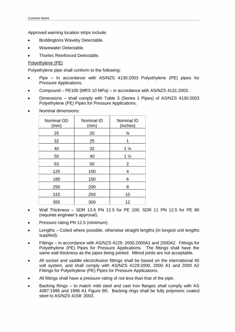
Dimensions – shall comply with Table 3 (Series 1 Pipes) of AS/NZS 4130:2003 Polyethylene (PE) Pipes for Pressure Applications.
Nominal dimensions:
Nominal OD (mm)
Nominal ID (mm)
Nominal ID (inches)
25 20 ¾
32 25 1
40 32 1 ¼
50 40 1 ½
63 50 2
125 100 4
180 150 6
250 200 8
315 250 10
355 300 12
Wall Thickness – SDR 13.6 PN 12.5 for PE 100, SDR 11 PN 12.5 for PE 80 (requires engineer’s approval).
Pressure rating PN 12.5 (minimum).
Lengths – Coiled where possible, otherwise straight lengths (in longest unit lengths supplied).
Fittings – in accordance with AS/NZS 4129: 2000,2000A1 and 2000A2. Fittings for Polyethylene (PE) Pipes for Pressure Applications. The fittings shall have the same wall thickness as the pipes being jointed. Mitred joints are not acceptable.
All socket and saddle electrofusion fittings shall be based on the international 40 volt system, and shall comply with AS/NZS 4129:2000, 2000 A1 and 2000 A2 Fittings for Polyethylene (PE) Pipes for Pressure Applications.
All fittings shall have a pressure rating of not less than that of the pipe.
Backing Rings – to match mild steel and cast iron flanges shall comply with AS 4087:1996 and 1996 A1 Figure B5. Backing rings shall be fully polymeric coated steel to AS/NZS 4158: 2003.

Contract Name
uPVC
All uPVC pipe shall comply with the following:
Pipe – in accordance with AS/NZS 1477: 2006 and 1999 A1. PVC pipes and fittings for pressure applications. Dimensions to be Series 1.
Pressure rating PN12 (minimum).
Jointing – Socket and Spigot elastomeric ring jointed. Solvent jointing is not acceptable.
Fittings – Socket/spigot type in accordance with AS/NZS1477: 2006 and 1999 A1 PVC Pipes and Fittings for Pressure Applications.
mPVC [Require Engineer’s Approval]
All mPVC pipe shall comply with the following:
Pipe - in accordance with AS/NZS 1477:2006 PVC pipes and fittings for pressure applications and to comply with Plastics Institute of NZ (Inc) Voluntary Manufacturing for Modified Poly Vinyl chloride (PVC-M) Pipes for pressure.
Pressure Rating – PN12 for urban schemes (minimum) and PN 16 or PN 20 as appropriate for rural schemes.
Jointing – Socket and Spigot elastomeric ring jointed. Solvent jointing is not acceptable.
Fittings – Socket/spigot type in accordance with AS/NZS1477: 2006 PVC pipes and Fittings for Pressure applications. “Blue Brute”/”Norcast Griptite” socketed fittings with a pressure rating of PN 16 or PN 20 to be used where practical or Engineer approved alternatives complying with the same standard.
Ductile Iron (DI)
All ductile iron pipe shall comply with the following:
Pipe - manufactured to AS/NZS 2280: 2004 Ductile Iron Pressure Pipes and Fittings. Class K9.
Joints - Socket-Spigot type.
Coating - Bitumen coated.
Lining - Cement mortar lined.
Corrosion protection - An approved polyethylene sleeving system to be applied to all ductile iron pipe laid underground and to be installed in accordance with AS3681:1989.
Service Pipes
Service pipes shall be Polyethylene PE80B or PE100 and comply with the following:
AS/NZS 4130: 2003 Polyethylene (PE) pipes for pressure applications.
Nominal ID – 20mm to 50mm.
Pressure rating – PN12.5.
Wall thickness – SDR11 for PE 80, SDR13.6 for PE100.
Length – Continuous roll.
Mechanical jointing (compression fittings) of PE pipes 63mm OD and smaller may be done using mechanical jointers manufactured to AS/NZS 4129:2000, 2000 A1
Contract Name
and 2000 A2 and complying with AS/NZS 4020:2002 Testing of products for use in contact with drinking water.
6.4 ALL RETICULATED SCHEMES
6.4.1 Valves & Fittings
Sluice Valves
(The type of valves to be installed are to be confirmed before the award of the contract).
All valves with a nominal ID of 50mm or larger shall comply with the following:
Manufactured to NZS/BS 5163:1986, 1986A1, 1986A2 “Predominantly Key Operated Cast Iron Gate Valves for Waterworks Purposes” (Type B); or
AS/NZS 2638.2:2003 “Sluice Valves for Waterworks Purposes.
Resilient seated wedge gate valves (wedge fully encapsulated in an approved synthetic rubber.
Pressure rated to PN16 (minimum).
Anti clockwise closing.
Fully polymeric coated to AS/NZS 4158:2003 “Thermal-bonded Polymeric Coatings on Valves and Fittings for Water Industry Purposes”.
Full flow bore with no restrictive gate seats.
Fitted with a removable valve cap for key operation.
Sealing of the stem shall be by o-rings, capable of being replaced under pressure.
All bolts, nuts, washers etc shall be 316 stainless steel.
Standard Pattern Swivel Ferrule
The ferrules shall be designed with EBCO compression outlet for PE. All ferrules shall be designed as a main stem with a 360 o swivel outlet at 90 o with control of water flow via a threaded inner plug. The inlet shall be a male taper thread to BS 21(SO 7/1).
The ferrule shall be designed for use underground and to handle potable water at temperatures of up to 40o C.
The ferrule shall work at pressures up to 16 bar (240 psi) without leakage.
The compression outlet for PE shall consist of the following: A serrated copper insert, a friction washer, a compression gland and a thrust nut.
ELGEF plus modular system or Tapping Tee and Electrofusion Saddle (only applicable to DN 63 PN12.5 PE 100 ridermain)
Tapping Tee
PE 100 SDR 11 ISO S5
16 bar water
with integrated cutter to tap live mains under pressure
long fusion outlet
O-ring sealed screwcap
PE 100 SDR 11 (ISO S5)
Contract Name
Electrofusion Saddle
16 bar water
complete with lower part
4mm pin connectors
limited path fusion indicators
Gate Valves
All valves with a nominal ID of less than 50mm shall comply with the following:
Shall comply with AS 1628, be constructed of DZR Brass and be PN20 rated (minimum).
Toby Valves
Acuflo manifold (Code GM 900S) with screw operated diaphragm valve, double check valve and metering point.
Toby Surface Boxes
Acuflo manifold Polypropylene box (AMB 300P) with mounting base where manifolds are installed.
Surface Boxes
Valve boxes shall be cast iron, circular loose lid in accordance with Plan A – 2118 Water Works Fitting Cast Iron Valve Box. Risers shall be approved precast concrete products suitable for the application. No Timber risers or packers are to be used.
Fire Hydrant boxes shall be cast iron, Heavy Duty Pattern to the Dimension shown on Plan 5304 Sheet 2 and have the lid painted in accordance with NZS 4501:1972, 1972A1 prior to installation. Lids shall be uniform fitting free from traffic movement and rattle. Fire Hydrant Box and Lid shall be tested and certified to Appendix C, Class D AS3996-2006 with an ultimate Design load of 210kN.
Approved FH boxes and lids are:
1 Austin Foundry Fire Hydrant Box (deep frame) Part Number 8
2 Saint Gabion – Warrior – HB36
All Hydrant Lids shall be supplied painted yellow with a fit for purpose painting system.
Hydrant and riser boxes shall be approved pre-cast concrete products.
Concrete pads for supporting the surface boxes shall be approved concrete products.
Fire hydrants
All fire hydrants shall comply with the following:
Constructed in accordance with NZS/BS750:1984, 1984 A1. Underground Fire Hydrants and Surface Box Frames and Covers.
Screw-down type.
Clockwise closing.
Resilient seated.
Medium or tall pattern unless otherwise specified or approved.
Hydrants shall not have unclosed frost or drain plugs.
Sealing of the stem shall be by o-rings.
Contract Name
Where the roadway is sealed raised Fire Hydrant Markers are to be installed adjacent to the road centreline and perpendicular to the new fire hydrant location.
Raised Fire Hydrant (type A) Markers shall be coloured blue and shall be as specified in TNZ M/12:1998 specification for raised Pavement Markers and TNZ M/12:2002 notes. Installation of the markers is to be to TNZ P/14:1995 Specification for the Installation of Raised Pavement Markers.
Installation of the markers is to be to TNZ P/14:1995 Specification for the Installation of Raised Pavement Markers.
Bends, Tapers, Tees, Adaptors and Fire Hydrant Risers
All fittings associated with the works, including bends, tees, tapers, adaptors and fire hydrant risers shall be ductile iron and manufactured in accordance with AS/NZS 2280. DI fittings shall be rated 16 bar minimum and be epoxy coated with Rislan Nylon 11 or approved equivalent.
PE100 PN16 Fire Hydrant Riser requires Engineer’s approval before installation.
Compression Couplers
Viking Couplers/PE
Minimum PN16 manufactured to AS/NZS 4129:2008 for rural scheme.
Brass Fittings
All brass fittings shall be minimum PN40 rated. The construction shall be heavy duty wall rated. All brass shall be type DZR. All brass fittings are to be discouraged and only to be used in situations where a PE fitting is not suitable. All brass and galvanised fittings are to be wrapped in two layers of DENZO tape if buried.
Valve Packing
PTFE
Hydrant Washer
Polyurethane cup
Flanges
To BS10 Table D
Frost Protection
All above ground pipe work less than DN80 requires frost protection with ARMAFLEX, 25mm thick wall. To be UV protected with ARMAFLEX finish paint or similar approved.
Air Valves
ARI D-040 for PN16
ARI S-052 for PN25
6.4.2 Denso Protection System
All buried flanges, bolts and gibaults that are not stainless steel shall be totally encased in petrolatum mastic paste, denso tape and denso over wrap tape or an approved equivalent system.
6.4.3 Concrete
Cement, aggregate and water shall conform to NZS3109:1997, 1997A1 and 1997 A2.
If requested, samples shall be supplied to the Engineer for testing.

Contract Name
Concrete production shall be in accordance with NZS 3104:2003.
The minimum strength of the concrete shall be 17.5 MPa at 28 days unless specified on the plans. Higher strength concrete shall be used where early loadings will be applied.
The slump of the concrete shall be kept to a value consistent with satisfactory placement. The maximum slump shall not be greater than 80mm.
Contract Name
7. DRAINAGE AND WATER SPECIFICATION – PRESSURE TESTING AND CHLORINATION/DECHLORINATION OF PIPELINE
7.1 METHODOLOGY - ACCEPTANCE TESTING, AND COMMISSIONING OF PIPELINES
The Contractor shall pressure test all pipework and fittings detailed on the Construction Drawings to the satisfaction of the Engineer. The Contractor may carry out a series of tests as work progresses but the final acceptance test(s) shall be carried out after all permanent supports and anchors have been constructed and all “closer” pipes have been installed. A record of all tests shall be made and shall be forwarded to the Engineer within 24 hours of test completion.
The Contractor shall have contingency plans and sufficient equipment on site to deal with any bursts or other foreseeable emergency that may arise during pressure testing. The Contractor shall supply all materials, equipment and labour required to carry out the required testing. Pressure testing is intended to:
1 Reveal the existence of any assembly and/or structural faults.
2 Ensure the pipeline can operate without leakage under foreseeable operating conditions.
7.2 NOTIFICATION AND PRE-REQUISITES
The Engineer shall be given at least 24 hours notice prior to acceptance testing. No acceptance test shall be carried out without the Engineer’s approval. Acceptance testing shall not be commenced before all of the following have occurred:
The section of pipeline to be tested has been completed, backfilled and conforms with the specification.
Means for filling, pressurising, measuring volumes and pressures, and flushing are in place. Such means must either fully comply with this specification, or be submitted in a written methodology to the Engineer for approval prior to commencing testing.
At least 24 hours’ notice of the intention to start testing has been given to the Engineer.
Any permanent or temporary concrete thrust blocks have been poured and have attained sufficient compressive strength to resist test thrusts.
End caps (that allow for filling and bleeding of air) and any temporary anchors are in place and are adequately braced to resist test thrusts.
Air valves are installed and their isolating valves are open.
Suitable measures are in place to record volume of water added or removed as required.
Arrangements have been made for the safe and legal disposal of water flushed from the pipeline.
Suitably qualified personnel are on site to carry out and oversee the testing.
Appropriate and approved record sheets are available for recording all aspects of the testing procedure.
Contract Name
7.3 PERSONNEL QUALIFICATIONS
The testing of all pipelines shall be carried out and supervised by acceptably qualified or accredited personnel. Qualified or accredited personnel shall:
Hold appropriate qualifications issued by a registered training organisation, or
Have attended a relevant training course, and received accreditation relating to the work being undertaken, and
Show competence and knowledge of the relevant testing methods and procedures.
7.4 TESTING
7.4.1 TESTING FOR DRAINAGE AND NON-PRESSURE PIPELINES
All new sewer, stormwater drainage and other non- pressure installation shall be tested using one of the methods in accordance to AS/NZS 2032.
Hydrostatic Test
Low Pressure Air Test
Vacuum Test
7.4.2 SECTIONS TO BE TESTED
The Contractor shall ensure that the correct test procedure is used for each pipeline material. The Contractor may divide testing into sections with the agreement of the Engineer where circumstances dictate. The pipeline shall not connect to the existing reticulation during the test phase until it has approval from the Engineer.
7.4.3 FILLING AND FLUSHING THE PIPELINE
The Principal will make water available from the reticulation for the first filling and flushing operations at no cost to the Contractor.
The taking of water for filling, flushing and testing shall meet all of the Principal’s requirements. Water used for any subsequent fill/s and flushing may be charged at the Principal’s current supply rate. The quantity of water to be charged shall be as measured by meter or as assessed by the Engineer if suitable metering equipment is not used. The maximum rate of take shall not exceed 10 L/s unless approval is obtained from the Principal for a higher rate of flow. Should the Contractor’s filling operations cause a disruption to supply by exceeding the allowed abstraction rate, or by unacceptably lowering the mains pressure, permission to take water may be withdrawn and the Contractor may need to provide potable water from an approved alternative source at their cost. The pipeline shall be filled at the maximum approved rate (or less), in accordance with the following conditions:
Preferably fill from the low end and ensure that air valves and venting points are open and operating.
A polyurethane foam swab shall be run along with the filling water to assist with debris and air removal.
Repair any leaks or make good any defects that are revealed.
Allow the test section of the pipeline to “soak” for a period of at least 60 minutes under positive pressure in all sections to allow the temperature to stabilise and any time dependent movement to take place. Concrete or cement mortar lined pipelines shall be soaked for at least 3 hours.
Contract Name
Where the test water is derived from a potable water supply, the filling or flushing
operations shall not cause an unacceptable pressure drop in the reticulation.
An approved backflow preventer (double check valve or better) shall be fitted to protect the potable water network.
Note that filling may be combined with disinfection at the Contractor’s risk.
7.4.4 SYSTEM TEST PRESSURE (STP)
The pressure shall be monitored at the lowest part of the test section or if that is not possible, at some other convenient point, and the test pressure adjusted to achieve a system test pressure (STP) as specified (for water mains <DN200 equals 1.125 times the lowest rated component or ≥ DN200 equals 1.5 times the operating pressure, i.e. DN100 water main, PN12 = 1350 kPa). The adjustment shall be made by adding 10 kPa for every metre elevation that the test rig and monitoring point is above the lowest point of the pipeline. If the STP has not been specified, it shall not be less than 900 kPa or more than 1.125 times the pressure rating of the lowest rated pipe or pipeline component. The pressure shall not exceed the PN rating of the lowest rated pipe or component in the pipeline by more than 20% at any time. If over-pressurisation is considered by the Engineer to have compromised the pipeline integrity, the Contractor shall be liable for all costs involved in replacing and relaying the over-stressed section(s) of pipeline.
If a motorised test pump is used, it shall be fitted with an adjustable pressure relief valve that is set to discharge the full flow of the pump at the test pressure. The test pump shall not create pulsations that may affect the ability to achieve the test pressure accurately. A suitable surge-damping device may be needed to control pressure pulsations.
7.4.5 TESTING AGAINST A CLOSED VALVE
Pressure testing against a closed valve may be undertaken when ay leakage from the valve can be observed and measured during the test. If leakage past a valve cannot be observed and measured, a test may be carried out at the Contractor’s risk, however, a pressure test against a closed valve that fails the maximum make-up water allowances shall be repeated using a different isolating device and/or location. All costs associated with a failed test against a closed valve shall be borne by the Contractor.
7.4.6 UNTESTABLE SECTIONS
Where sections or connections cannot be practicably tested (e.g. connections to existing pipelines), and with the agreement of the Engineer, those sections or connections shall be left exposed until after the pipeline is commissioned. Any visible leakage shall be made good before backfilling and a final inspection carried out in the presence of the Engineer.
Any repair works shall be at the Contractor’s expense.
7.4.7 COMPLETION OF THE TEST
After testing, release the test pressure slowly and if necessary, open air valves and drain points to drain the line. If the pipeline has been disinfected, do not drain it until just prior to the final connection and commissioning so that the risk of contamination is minimised.
7.4.8 REPORTING
On satisfactory completion of the test, the test report shall be prepared by the Contractor and signed off by the Contractor and Engineer witnessing the test. The test report shall include the following:

Contract Name
Details of the pipeline section tested, including details of pipe manufacturer’s
identification details, jointing system, pipeline profile showing any changes in elevation, as well as the location of valves and fittings.
Date and time of testing (both start and finish).
Failure of any thrust block, pipe, fitting or other component and its location.
Any visible leakage detected and repaired.
For PE pipe testing, a record of the datalogged pressure in the pipeline in .csv or .xlsx format.
The volume of make up water and the volume of allowed make up water.
Names of key personnel and observers.
7.4.9 FAILURE OF TEST
Should the test fail, the cause(s) shall be located, rectified and the section re-tested and repaired until satisfactory results are obtained (at the contractor’s cost).
Should the test fail on more than two occasions the Engineer’s presence at subsequent retests shall be charged at $70.00 per hour.
7.5 STERILISING AND TURBIDITY
All sterilising and subsequent flushing of new pipes shall be completed and approved by the Engineer prior to connection to the existing water supply network.
The main and water service laterals are to be thoroughly flushed with clean potable water to remove any extraneous matter.
A chlorine based sterilising solution shall then be introduced into the main so that a F.A.C. concentration of 50 P.P.M is available.
This shall be retained no less than 10 P.P.M and turbidity shall be less than 5NTU in the main for a period of 24 hours at the completion of which all valves shall be operated. A neutralising solution shall then be introduced into the main to return the chlorinated solution to a FAC level less than 0.4ppm and no chlorine odour is detected.
The main shall then be flushed with clean potable water until the FAC. level is less than 0.4 PPM. and no chlorine odour is detected. In addition the turbidity shall be less than 5NTU.
All fittings etc. for connecting the new main to the network, not included in the above sterilising procedure, shall be internally washed or sprayed with chlorine based sterilising solution immediately prior to installation.
7.6 MICROBIOLOGICAL TEST FOR NEW LIVENED MAINS
Within 12 hours of the new watermain being livened, the Contractor shall collect one random sample of water for microbiological testing. The sample, to be collected and tested at the expense of the Contractor, shall be tested for E-coli.
The new pipelines are deemed to have passed the microbiological test if the E-coli result is 0/100mL.
If the E-coli test fails, the Contractor shall follow the procedure, as specified in the DWSNZ.
Contract Name
7.7 DISINFECTION OF EXISTING MAINS
This Contract work requires work on existing mains while they are in service, including the installation, replacement and removal of fittings during connection of new mains and disconnection of redundant mains. The Contractor shall follow the disinfection procedures outlined below:
To prevent ingress of contamination through the failed pipe, draining watermains through hydrants shall only be done where all of the section of pipe being drained is fully intact, i.e. where the pipe has no cut or broken areas. Watermains that have been cut or broken shall only be drained through the cut or broken area (e.g. where a piece of pipe has been removed to install a branch tee), while the level of the wastewater in the trench is kept well below the cut area of the pipe. The disinfection of repaired mains depends on the risk criteria and is explained with appropriate action. All repairs shall be classified i.e. low risk/medium risk/high risk and recorded in accordance with the Work Information Requirements.
Low Risk Situations
Low Risk Situations/ Repairs under Positive Pressure Low risk situations are where the pressure in the pipe is maintained while carrying out work which involves cutting or tapping into the live main (e.g. installing service connection, or a branch connection using live tapping techniques). The procedure shall be:
Spray all surface of fittings and the exterior of the watermain with 5% chlorine solution e.g. undiluted household bleach liquid
For chlorine cleaning solution refer to APPENDIX A Mixing Chlorine Cleaning Solution
Medium Risk Situations
Medium risk situations are where the pressure in the main is lost but no foreign matter or groundwater enters the main. Controlled draining of the main will be into the trench under the work area and no external solid or liquid material makes any contact at all with the open section of the main. Thorough dewatering of the trench must be carried out with a sump created in the bottom of the excavation. Clean water flowing or draining from the pipe into the sump is an indication that the situation remains at medium risk.
The required procedure is as follows:
Spray all surfaces of fittings and the exterior and interior of both ends of the main with 5% chlorine solution
For chlorine cleaning solution refer to APPENDIX A Mixing Chlorine Cleaning Solution
After completion of all work, flush the main out from hydrants in each direction consecutively for a minimum of 5 minutes
High Risk Situations
High risk situations are where any external solid or liquid material has entered the main or where upon excavation it is evident that chemically contaminated liquid, or faecal contamination is present in the excavation, and there is an obvious health risk associated with working on the watermain in this environment. Contamination of the main shall be considered to be high risk if:
There are any foul or Stormwater drains near the break
There are any septic tanks, sewage reticulation pump stations or plants in the immediate vicinity of the break, or
Contract Name
Runoff water from the road or verge has been able to flow into the trench during
the excavation and repair
Water flows into a fire hydrant used for bleeding or draining
Water has the ability to flow into the main via the leak, repairs or during bleeding, or raining
The procedure during high risk situations shall be:
Contact and inform the Engineer
Isolate the watermain to prevent further travel of the contaminated water
If practical, isolate all affected service connections
If the excavation is badly contaminated, apply liberal amount of HTH powder or granules or use the spray bottle to spray around the affected areas to reduce the risk of contamination
Drain the watermain through a cut section while keeping the trench water level well below the level of the cut pipe
While maintaining this water level in the trench, flush as much of the contaminated material as possible from the watermain through the cut area by opening valves at either end of the isolated portion of the reticulation system
Refer to APPENDIX A to APPENDIX E
In extreme cases the main will only be commissioned once the bacterial tests have been received

Contract Name
8. METHOD OF MEASUREMENT AND BASIS OF PAYMENT
8.1 METHOD OF MEASUREMENT
8.1.1 UNITS OF MEASUREMENT
Units of measurement shown in the "Unit" column of the schedules have been abbreviated as follows:
LS Lump Sum
m Lineal metre
m2 Square metre
m3 Cubic metre
ea Each
% Percent
8.1.2 MEASUREMENT DETAILS
8.1.2.1 Measurements General
Accuracy – all measurements shall be to the nearest 100mm.
Pipework Distance – the start and finish of pipework lineal measurements shall be taken at the pipe joint between the old existing pipe and the new pipe laid.
8.1.2.2 Measurements Specific
Sewer Main Renewals in Road Reserve or Private Property – The per metre rate measurement for sewer main relays includes all junctions and lateral connections required within the trench walls, as per the standard plans.
Sewer Service Line Relays in Road Reserve – Where the sewer service line relay is being carried out in conjunction with a sewer main relay measurement for the sewer service line will start at the sewer main relay trench wall.
8.2 BASIS OF PAYMENT
8.2.1 GENERAL
The unit rate set out in the Schedules shall be deemed to include:
a) The cost of complying with all conditions, obligations and liabilities described in the General and Special Conditions of Contract, the Specifications, including the supply of all plant, equipment, labour and materials indicated or implied in these documents.
b) All sundry costs and incidental items i.e. insurances, bond, permit fees and necessary notices, payment of all fees legally due as required by Government and Local Authority, setting out of site, and traffic control.
8.2.2 PROGRESS PAYMENTS
As this is a Measure and Value Contract and the time for completion is * Weeks the Contractor shall submit a claim at the end of each month giving details of all works executed up until that date.
Contract Name
Payments will be made without prejudice on agreed values of the work completed and materials used.
Variations will be priced from the Schedule of Quantities where applicable and by Dayworks rates where not applicable.
All work for which extra payment is expected shall be approved in writing by the Engineer.
8.2.2.1 Site Establishment and Disestablishment
The Contractor shall provide a lump sum to cover the establishment and disestablishment on each site of all plant and buildings required for the efficient execution of the work, and the removal of such plant, buildings materials and final clearing as specified elsewhere in the specifications.
8.2.2.2 Traffic Control
The Contractor shall cover the cost of providing for the smooth safe passage of ordinary road and pedestrian traffic. The lump sum shall cover the supply, erection and maintenance of all necessary road signs, barricades, lights and other equipment and shall include all costs associated with the provision of traffic controllers.
Should the traffic control not meet with the standards required, the Engineer may withhold payment due or require additional work to be completed to meet with the requirements.
8.2.2.3 Sewer Main Rehabilitation
Payment will be by Unit Rate, in Schedule of Prices for the completed works measured in position including:
Sewer rehabilitation including any excavation, saw cutting, timbering and removal and disposal of all excavated material as per the specifications including any manholes.
Supply, cartage and placement as per the specifications of bedding, screened river run backfill AP 65, TNZ M4/ AP 40 backfill.
Supply, cartage and installation as per the specifications of all pipework and fittings including the reconnection of all service lines in main line replacement works, between the pipeline and the main trench wall.
Testing as required in the specification.
As – Built drawings as per clause in Section 9 - Plans and Drawings.
Surface restoration including the sealing of the excavations, and/or the placement of asphaltic concrete (including the waterproof layer) required as per the specification.
All other works required to complete the construction as described in the specification and drawing.
8.2.2.4 100mm Dia Service Connection Relay
Payment will be by Unit Rate for the completed works measured in position from the wall of the main trench to the end of the particular service connection relay; including supply and cartage of materials, excavation and pipelaying etc.
Payment will only be for works specifically ordered by the Engineer after the service connection testing.
Contract Name
8.2.2.5 150mm Dia Service Connection Relay
Payment will be by Unit Rate for the completed works measured in position from the wall of the main trench to the end of the particular service connection relay; including supply and cartage of materials, excavation and pipe laying etc.
Payment will only be for works specifically ordered by the Engineer after the service connection testing.
8.2.2.6 100mm Dia Oblique Junction
Payment will be by Unit Rate for the completed oblique junction on the main gully line; including supply and cartage of materials, excavation and laying etc.
8.2.2.7 150mm Dia Oblique Junction
Payment will be by Unit Rate for the completed oblique junction on the main line gully; including supply and cartage of materials, excavation and laying etc.
8.2.2.8 100mm Dia Oblique Junction
Payment will be by Unit Rate for the completed oblique junction on the branch line; including supply and cartage of materials, excavation and laying etc.
8.2.2.9 150mm Dia Oblique Junction
Payment will be by Unit Rate for the completed oblique junction on the branch line; including supply and cartage of materials, excavation and laying etc.
8.2.2.10 Sewer Manhole Construction
Payment will be by Unit Rate for the completed manhole and shall include the following:
Excavation, removal and disposal of all excavated material including existing manholes.
Supply cartage and placement of bedding and backfill materials.
Supply cartage and installation of all pipework including bends, junctions, sleeves and joiners.
Supply, cartage and construction of the manhole including lids and castings to complete the construction as detailed in the specifications and drawings.
8.2.2.11 *mm Stormwater Main
Payment will be by Unit Rate, in Schedule of Prices for the completed works measured in position including:
Excavation, saw cutting, timbering and removal and disposal of all excavated material as per the specification including any sumps and manholes.
Supply, cartage and placement as per the specifications of bedding, screened river run backfill AP 65, TNZ M4/AP 40 backfill.
Supply, cartage and installation as per the specifications of all pipework and fittings including the reconnection of all service lines in main line replacement works, between the pipeline and the main trench wall.
Testing as required in the specification.
As – Built drawings as per clause in Section 9 - Plans and Drawings.
Contract Name
Surface restoration including the sealing of the excavations, and/or the placement
of asphaltic concrete (including the waterproof layer) required as per the specification.
All other works required to complete the construction as described in the specification and drawing.
8.2.2.12 Stormwater Manhole Construction
Payment will be by Unit Rate in the Schedule of Prices for the completed works.
8.2.2.13 300mm Diameter Stormwater Sump Pipework
Payment will be by Unit Rate in the Schedule of Prices for the completed works measured in position from the sump wall to the end of the renewal; including supply and cartage of materials, excavation and pipelaying etc.
8.2.2.14 Double Sumps
Payment will be by Unit Rate for the completed double sump and shall include the following:
Excavation, removal and disposal of excavated material including existing sumps.
Supply, cartage and placement of all backfill materials.
Supply, cartage and installation of all pipework including bends, junctions, sleeves and joiners.
Supply, cartage and construction of the double sumps including gratings and kerb and channel reinstatement as detailed in the specifications and drawings.
8.2.2.15 *mm & *mm ID Watermain
Payment will be made on a per metre basis to cover all costs for the completed works measured in position including:
(i) Excavation to such depths and alignments as required to permit the proper execution of the works, sawcutting, timbering and removal and disposal of material.
(ii) Supply, cartage and placement as per the specification of bedding and backfill material.
(iii) Supply, cartage and installation of pipes, fittings and materials including valves (50mm and less) but excluding sluice valves (50mm and above), thrust blocks.
(iv) Surface restoration.
(v) Testing and sterilising as required in the specification.
(vi) As – Built drawings as per clause in Section 9 - Plans and Drawings.
(vii) Any other works required to complete the construction of the Watermain as described in the specification and drawings.
8.2.2.16 20mm to 32mm ID water services
Payment will be made on a per metre basis to cover all costs for the completed works measured in position from the water main to the centre of the manifold. This includes excavation, supply and cartage of materials, installation etc plus connection of the new service to the new main.
Contract Name
8.2.2.17 Connection of water service laterals
Payment shall be made on a per each basis for the completed works to cover all costs associated with excavation, supply and cartage of materials:
For the installation/replacement of the toby with a new manifold and surface box.
Connection of existing service laterals to the new watermain. It is anticipated that some of the existing water service laterals will be able to be connected onto the new watermain without the need of being relaid. The schedule rate shall apply in those instances.
8.2.2.18 Fire Hydrants, Water Meters, Flushing Points and Air Valves
Payment shall be made on a per each basis for the completed work to cover all costs for the supply and installation of fire hydrants, water meters, flushing points and air valves all in their correct level and position. This also covers the cost of the installation of the blue fire hydrant markers (in Temuka, Geraldine and Pleasant Point only) and fire hydrant markings.
All riser boxes and other required fittings shall be supplied by the Contractor.
8.2.2.19 Sluice Valves – 50mm or bigger
Payment shall be made on a per each basis for the completed work to cover all costs for the supply and installation of sluice valves (50mm diameter or bigger), associated fittings, anchor blocks and valve surface covers all in their correct level and position.
8.2.2.20 Connections of new main to existing network
Payment shall be made on a lump sum basis for the completed work to cover all costs associated with connections to the existing water supply network not covered elsewhere in the specification.
8.2.2.21 Disconnection’s and Recovery
Payment shall be made on a lump sum basis for the completed work to cover all costs associated with excavation, supply and installation of materials, backfill and reinstatement for the disconnection of existing surplus mains and recovery of any existing fire hydrants, sluice valves, water meters, surface boxes and fittings to the Council’s Claremont Reservoir site as required including plugging of abandoned pipes.
Disconnection includes removal of connector fittings in the adjacent network and replacing with straight sections of pipe unless shown otherwise on the plan.
This item includes the permanent removal of old surplus fire hydrant markings.
8.2.3 GOODS AND SERVICE TAX
The unit rates shown in the schedules submitted by a person registered in terms of the Goods and Service Tax Act 1985 shall exclude GST.
8.2.4 DAYWORK RATES
The total amounts included in the schedules to cover dayworks i.e. labour, plant and materials will not necessarily be carried out in full, but will be arranged strictly under the provisions of Clause 9.4 of the General Conditions of Contract.
Contract Name
8.2.4.1 Labour
A completed schedule of dayworks rates are to be provided in the Schedule. The rates quoted are to be net costs only.
It is required to quote the percentage addition to the net cost of wages paid to cover all contractor’s on costs, superintendence, insurance and all allowances to labour including accommodation and travelling costs, holiday with pay, profit, time keeping and all clerical and office work as well as transport about the site and the use of all minor equipment and all incidental charges whatsoever, but excluding incentive payments and penal portion of overtime payments.
Work done on daywork shall be restricted to normal working hours and shall be paid at single time rates unless specific approval in writing is given by the Engineer. The rate of pay for approved overtime shall be the submitted rates for each class of workman multiplied by the Overtime Work Multiplier supplied by the Contractor in the Dayworks Schedules.
Note: The time of Gangers or Charge hands working with their gangs will be paid for at rates quoted, but the time of foreman is to be covered by the percentage additions above.
8.2.4.2 Plant
A completed schedule of hourly plant hire rates are to be provided in the Schedules.
Rates quoted are to cover net cost per working hour for the use of each item of plant and shall exclude Operators Wages.
It is required to quote the percentage addition to the net cost of plant hire on dayworks to cover (where not already included in the hire rate) all insurance, maintenance, wear and tear, spare parts and all costs of repairs and renewals, all fittings and all equipment of whatever nature required for the efficient operation of the plant, standing time, profit, all fuel and consumable stores, electric power and general superintendence. Operator’s time will be paid for separately.
8.2.4.3 Materials
A completed schedule of material rates are to be provided in the Schedules.
It is required to quote the percentage addition to the net cost of material used on dayworks to cover all overhead charges, profit and all incidental costs whatsoever.
The percentage additional shall apply to all materials delivered to the site and authorised by the Engineer to be used in dayworks. The net quantities and weights actually used in accordance with the Engineer’s instructions only shall be certified and paid for.
8.2.4.4 Materials Percentage On Cost
The Contractor shall nominate any additional cost over and above the net actual cost of materials for the materials approved by the Engineer purchased by the Contractor to be under daywork rates and shall cover the Contractor additional expenses for costing, transporting, etc. involved in obtaining the materials.
To ensure that suitable materials are of the lowest price available at the time the Contractor is to use quotations for all major purchases and have purchase contract in place for various categories of produce. The Contractor may be required to provide proof to the Engineer that their quotation procedures are transparent and that competitive prices for materials are being obtained.

Contract Name
9. PLANS AND DRAWINGS
9.1 INTRODUCTION
The following plans and drawings are to be read in conjunction with this specification and detail the work to be completed within the contract.
9.2 PLANS
PLAN NUMBERS
9.3 STANDARD DRAWINGS
TRENCH, EMBEDMENT, TRENCHFILL AND REINSTATEMENT DETAILS
5301 Sheet 1 of 2 – Reinstatement and flexible pipe details
5301 Sheet 2 of 2 – Concrete pipe details and pipe protection details
DRAINAGE (SEWER and STORMWATER))
5302 Sheet 1 of 12 – Typical precast concrete manhole details
5302 Sheet 2 of 12 – Typical precast concrete manhole details and drop structures
5302 Sheet 3 of 12 – Access refurbishment and connection details to concrete manhole
5302 Sheet 4 of 12 – Manhole ladder, step rung and lateral connections
5302 Sheet 5 of 12 – Service lateral / cleaning eye / ramped riser
5302 Sheet 6 of 12 – Pole vent details
5302 Sheet 7 of 12 – Inlet and Outlet details and soakage pit
5302 Sheet 8 of 12 – Typical sump / catch pit details
5302 Sheet 9 of 12 – Drainage siphon kerb exit details
5302 Sheet 10 of 12 – Single and double stormwater splay pit
5302 Sheet 11 of 12 – Access or right of way sump
5302 Sheet 12 of 12 – Details of stormwater crossing, footpath to kerb and channel
WATER SUPPLY
5304 Sheet 1 of 5 – Deviations, anchorage, thrust blocks and joint wrapping details
5304 Sheet 2 of 5 – Hydrant and line valve installation details
5304 Sheet 3 of 5 – Scour and air valve installation details
5304 Sheet 4 of 5 – Service connection
5304 Sheet 5 of 5 – Rural water connection / tank details and reticulation sampling tap detail
A – 2118 – Waterworks fittings cast iron valve box
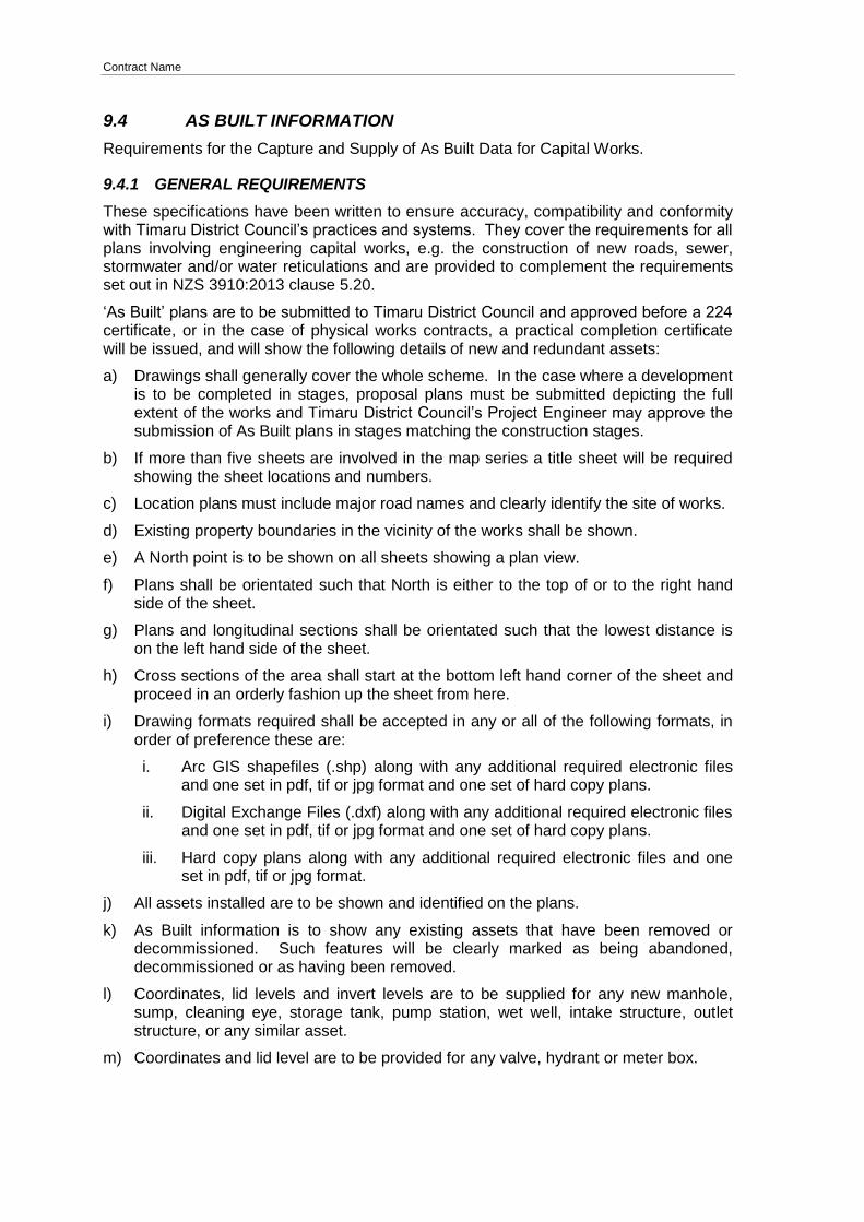
Contract Name
9.4 AS BUILT INFORMATION
Requirements for the Capture and Supply of As Built Data for Capital Works.
9.4.1 GENERAL REQUIREMENTS
These specifications have been written to ensure accuracy, compatibility and conformity with Timaru District Council’s practices and systems. They cover the requirements for all plans involving engineering capital works, e.g. the construction of new roads, sewer, stormwater and/or water reticulations and are provided to complement the requirements set out in NZS 3910:2013 clause 5.20.
‘As Built’ plans are to be submitted to Timaru District Council and approved before a 224 certificate, or in the case of physical works contracts, a practical completion certificate will be issued, and will show the following details of new and redundant assets:
a) Drawings shall generally cover the whole scheme. In the case where a development is to be completed in stages, proposal plans must be submitted depicting the full extent of the works and Timaru District Council’s Project Engineer may approve the submission of As Built plans in stages matching the construction stages.
b) If more than five sheets are involved in the map series a title sheet will be required showing the sheet locations and numbers.
c) Location plans must include major road names and clearly identify the site of works.
d) Existing property boundaries in the vicinity of the works shall be shown.
e) A North point is to be shown on all sheets showing a plan view.
f) Plans shall be orientated such that North is either to the top of or to the right hand side of the sheet.
g) Plans and longitudinal sections shall be orientated such that the lowest distance is on the left hand side of the sheet.
h) Cross sections of the area shall start at the bottom left hand corner of the sheet and proceed in an orderly fashion up the sheet from here.
i) Drawing formats required shall be accepted in any or all of the following formats, in order of preference these are:
i. Arc GIS shapefiles (.shp) along with any additional required electronic files and one set in pdf, tif or jpg format and one set of hard copy plans.
ii. Digital Exchange Files (.dxf) along with any additional required electronic files and one set in pdf, tif or jpg format and one set of hard copy plans.
iii. Hard copy plans along with any additional required electronic files and one set in pdf, tif or jpg format.
j) All assets installed are to be shown and identified on the plans.
k) As Built information is to show any existing assets that have been removed or decommissioned. Such features will be clearly marked as being abandoned, decommissioned or as having been removed.
l) Coordinates, lid levels and invert levels are to be supplied for any new manhole, sump, cleaning eye, storage tank, pump station, wet well, intake structure, outlet structure, or any similar asset.
m) Coordinates and lid level are to be provided for any valve, hydrant or meter box.
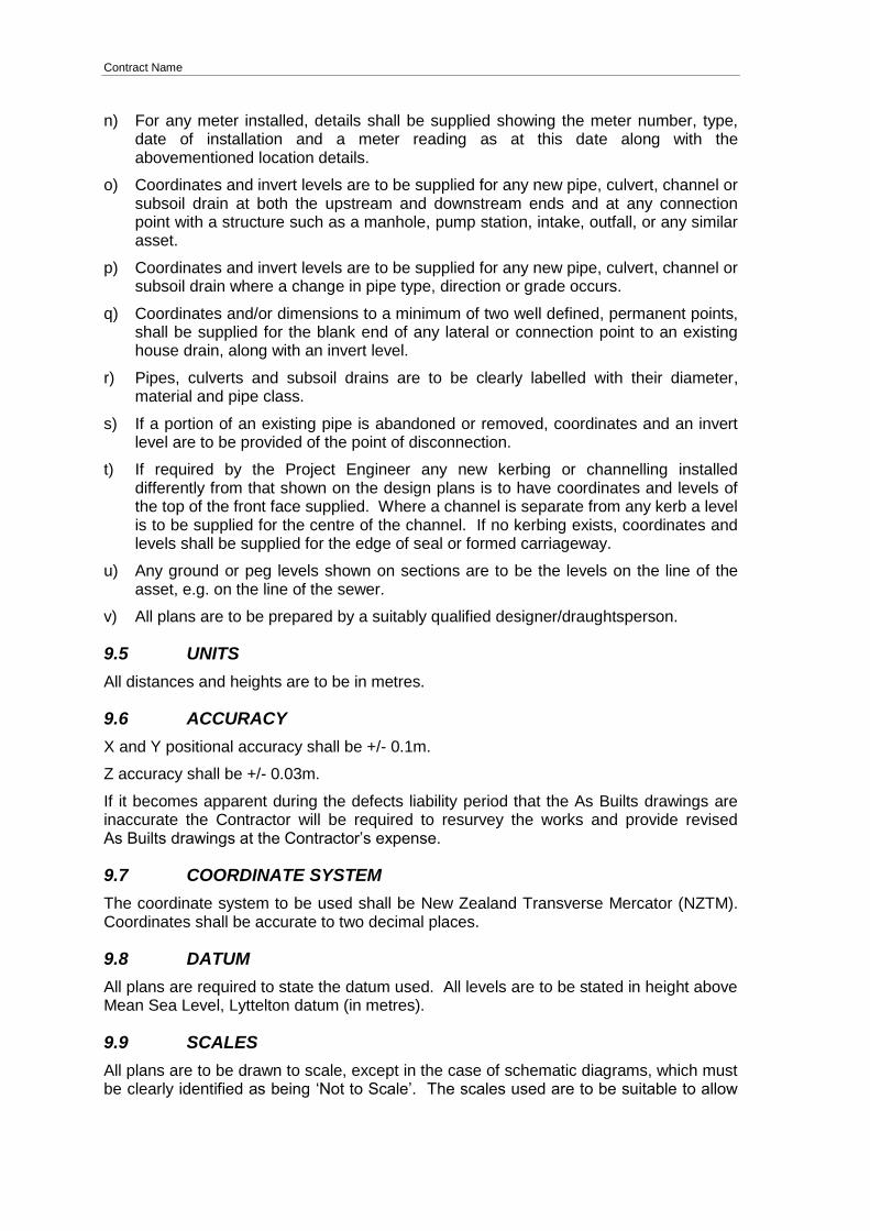
Contract Name
n) For any meter installed, details shall be supplied showing the meter number, type,
date of installation and a meter reading as at this date along with the abovementioned location details.
o) Coordinates and invert levels are to be supplied for any new pipe, culvert, channel or subsoil drain at both the upstream and downstream ends and at any connection point with a structure such as a manhole, pump station, intake, outfall, or any similar asset.
p) Coordinates and invert levels are to be supplied for any new pipe, culvert, channel or subsoil drain where a change in pipe type, direction or grade occurs.
q) Coordinates and/or dimensions to a minimum of two well defined, permanent points, shall be supplied for the blank end of any lateral or connection point to an existing house drain, along with an invert level.
r) Pipes, culverts and subsoil drains are to be clearly labelled with their diameter, material and pipe class.
s) If a portion of an existing pipe is abandoned or removed, coordinates and an invert level are to be provided of the point of disconnection.
t) If required by the Project Engineer any new kerbing or channelling installed differently from that shown on the design plans is to have coordinates and levels of the top of the front face supplied. Where a channel is separate from any kerb a level is to be supplied for the centre of the channel. If no kerbing exists, coordinates and levels shall be supplied for the edge of seal or formed carriageway.
u) Any ground or peg levels shown on sections are to be the levels on the line of the asset, e.g. on the line of the sewer.
v) All plans are to be prepared by a suitably qualified designer/draughtsperson.
9.5 UNITS
All distances and heights are to be in metres.
9.6 ACCURACY
X and Y positional accuracy shall be +/- 0.1m.
Z accuracy shall be +/- 0.03m.
If it becomes apparent during the defects liability period that the As Builts drawings are inaccurate the Contractor will be required to resurvey the works and provide revised As Builts drawings at the Contractor’s expense.
9.7 COORDINATE SYSTEM
The coordinate system to be used shall be New Zealand Transverse Mercator (NZTM). Coordinates shall be accurate to two decimal places.
9.8 DATUM
All plans are required to state the datum used. All levels are to be stated in height above Mean Sea Level, Lyttelton datum (in metres).
9.9 SCALES
All plans are to be drawn to scale, except in the case of schematic diagrams, which must be clearly identified as being ‘Not to Scale’. The scales used are to be suitable to allow
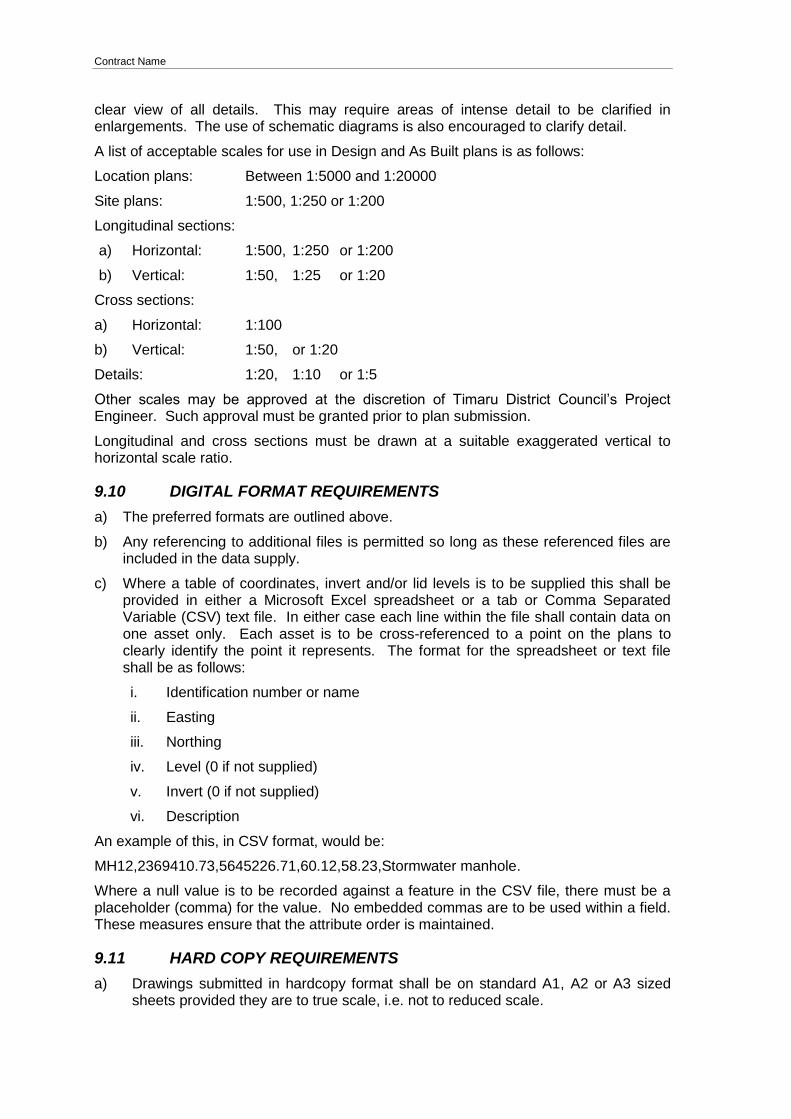
Contract Name
clear view of all details. This may require areas of intense detail to be clarified in enlargements. The use of schematic diagrams is also encouraged to clarify detail.
A list of acceptable scales for use in Design and As Built plans is as follows:
Location plans: Between 1:5000 and 1:20000
Site plans: 1:500, 1:250 or 1:200
Longitudinal sections:
a) Horizontal: 1:500, 1:250 or 1:200
b) Vertical: 1:50, 1:25 or 1:20
Cross sections:
a) Horizontal: 1:100
b) Vertical: 1:50, or 1:20
Details: 1:20, 1:10 or 1:5
Other scales may be approved at the discretion of Timaru District Council’s Project Engineer. Such approval must be granted prior to plan submission.
Longitudinal and cross sections must be drawn at a suitable exaggerated vertical to horizontal scale ratio.
9.10 DIGITAL FORMAT REQUIREMENTS
a) The preferred formats are outlined above.
b) Any referencing to additional files is permitted so long as these referenced files are included in the data supply.
c) Where a table of coordinates, invert and/or lid levels is to be supplied this shall be provided in either a Microsoft Excel spreadsheet or a tab or Comma Separated Variable (CSV) text file. In either case each line within the file shall contain data on one asset only. Each asset is to be cross-referenced to a point on the plans to clearly identify the point it represents. The format for the spreadsheet or text file shall be as follows:
i. Identification number or name
ii. Easting
iii. Northing
iv. Level (0 if not supplied)
v. Invert (0 if not supplied)
vi. Description
An example of this, in CSV format, would be:
MH12,2369410.73,5645226.71,60.12,58.23,Stormwater manhole.
Where a null value is to be recorded against a feature in the CSV file, there must be a placeholder (comma) for the value. No embedded commas are to be used within a field. These measures ensure that the attribute order is maintained.
9.11 HARD COPY REQUIREMENTS
a) Drawings submitted in hardcopy format shall be on standard A1, A2 or A3 sized sheets provided they are to true scale, i.e. not to reduced scale.

Contract Name
b) These sheets must not be folded or creased to enable clear reproduction of the
plans.
c) All draughting is to be legible.
d) All lettering shall be not less than 2.5mm tall in accordance with AS/NZS 1100.101 and shall be in Arial or similar approved font to enable clear reproduction of the plans.
e) The minimum thickness shall be 0.25mm for all line work.
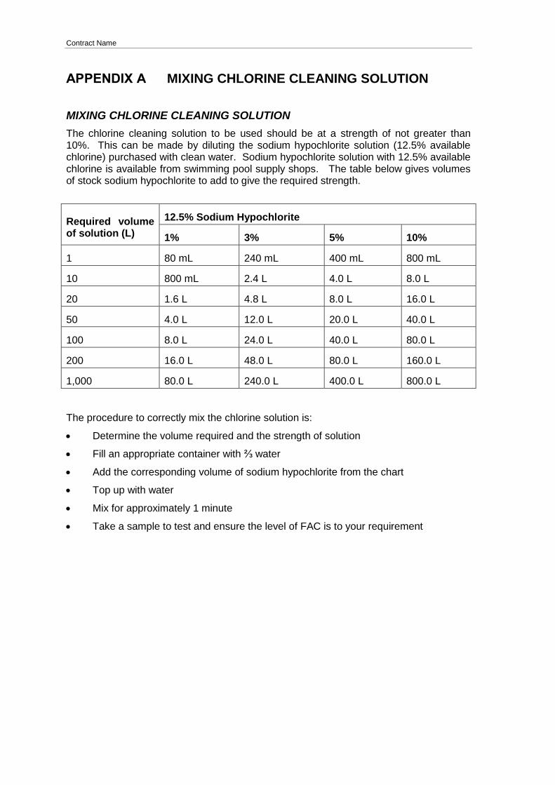
Contract Name
APPENDIX A MIXING CHLORINE CLEANING SOLUTION
MIXING CHLORINE CLEANING SOLUTION
The chlorine cleaning solution to be used should be at a strength of not greater than 10%. This can be made by diluting the sodium hypochlorite solution (12.5% available chlorine) purchased with clean water. Sodium hypochlorite solution with 12.5% available chlorine is available from swimming pool supply shops. The table below gives volumes of stock sodium hypochlorite to add to give the required strength.
Required volume of solution (L)
12.5% Sodium Hypochlorite
1% 3% 5% 10%
1 80 mL 240 mL 400 mL 800 mL
10 800 mL 2.4 L 4.0 L 8.0 L
20 1.6 L 4.8 L 8.0 L 16.0 L
50 4.0 L 12.0 L 20.0 L 40.0 L
100 8.0 L 24.0 L 40.0 L 80.0 L
200 16.0 L 48.0 L 80.0 L 160.0 L
1,000 80.0 L 240.0 L 400.0 L 800.0 L
The procedure to correctly mix the chlorine solution is:
Determine the volume required and the strength of solution
Fill an appropriate container with ⅔ water
Add the corresponding volume of sodium hypochlorite from the chart
Top up with water
Mix for approximately 1 minute
Take a sample to test and ensure the level of FAC is to your requirement
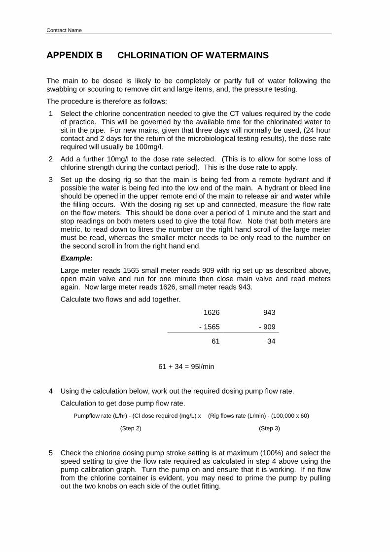
Contract Name
APPENDIX B CHLORINATION OF WATERMAINS
The main to be dosed is likely to be completely or partly full of water following the swabbing or scouring to remove dirt and large items, and, the pressure testing.
The procedure is therefore as follows:
1 Select the chlorine concentration needed to give the CT values required by the code of practice. This will be governed by the available time for the chlorinated water to sit in the pipe. For new mains, given that three days will normally be used, (24 hour contact and 2 days for the return of the microbiological testing results), the dose rate required will usually be 100mg/l.
2 Add a further 10mg/l to the dose rate selected. (This is to allow for some loss of chlorine strength during the contact period). This is the dose rate to apply.
3 Set up the dosing rig so that the main is being fed from a remote hydrant and if possible the water is being fed into the low end of the main. A hydrant or bleed line should be opened in the upper remote end of the main to release air and water while the filling occurs. With the dosing rig set up and connected, measure the flow rate on the flow meters. This should be done over a period of 1 minute and the start and stop readings on both meters used to give the total flow. Note that both meters are metric, to read down to litres the number on the right hand scroll of the large meter must be read, whereas the smaller meter needs to be only read to the number on the second scroll in from the right hand end.
Example:
Large meter reads 1565 small meter reads 909 with rig set up as described above, open main valve and run for one minute then close main valve and read meters again. Now large meter reads 1626, small meter reads 943.
Calculate two flows and add together.
1626 943
- 1565 - 909
61 34
61 + 34 = 95l/min
4 Using the calculation below, work out the required dosing pump flow rate.
Calculation to get dose pump flow rate.
Pumpflow rate (L/hr) - (Cl dose required (mg/L) x (Rig flows rate (L/min) - (100,000 x 60)
(Step 2) (Step 3)
5 Check the chlorine dosing pump stroke setting is at maximum (100%) and select the speed setting to give the flow rate required as calculated in step 4 above using the pump calibration graph. Turn the pump on and ensure that it is working. If no flow from the chlorine container is evident, you may need to prime the pump by pulling out the two knobs on each side of the outlet fitting.
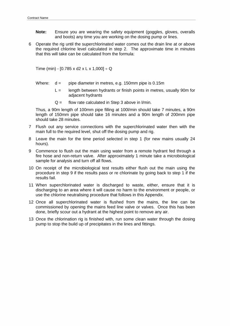
Contract Name
Note: Ensure you are wearing the safety equipment (goggles, gloves, overalls
and boots) any time you are working on the dosing pump or lines.
6 Operate the rig until the superchlorinated water comes out the drain line at or above the required chlorine level calculated in step 2. The approximate time in minutes that this will take can be calculated from the formula:
Time (min) - [0.785 x d2 x L x 1,000] Q
Where: d = pipe diameter in metres, e.g. 150mm pipe is 0.15m
L = length between hydrants or finish points in metres, usually 90m for adjacent hydrants
Q = flow rate calculated in Step 3 above in l/min.
Thus, a 90m length of 100mm pipe filling at 100l/min should take 7 minutes, a 90m length of 150mm pipe should take 16 minutes and a 90m length of 200mm pipe should take 28 minutes.
7 Flush out any service connections with the superchlorinated water then with the main full to the required level, shut off the dosing pump and rig.
8 Leave the main for the time period selected in step 1 (for new mains usually 24 hours).
9 Commence to flush out the main using water from a remote hydrant fed through a fire hose and non-return valve. After approximately 1 minute take a microbiological sample for analysis and turn off all flows.
10 On receipt of the microbiological test results either flush out the main using the procedure in step 9 if the results pass or re chlorinate by going back to step 1 if the results fail.
11 When superchlorinated water is discharged to waste, either, ensure that it is discharging to an area where it will cause no harm to the environment or people, or use the chlorine neutralising procedure that follows in this Appendix.
12 Once all superchlorinated water is flushed from the mains, the line can be commissioned by opening the mains feed line valve or valves. Once this has been done, briefly scour out a hydrant at the highest point to remove any air.
13 Once the chlorination rig is finished with, run some clean water through the dosing pump to stop the build up of precipitates in the lines and fittings.
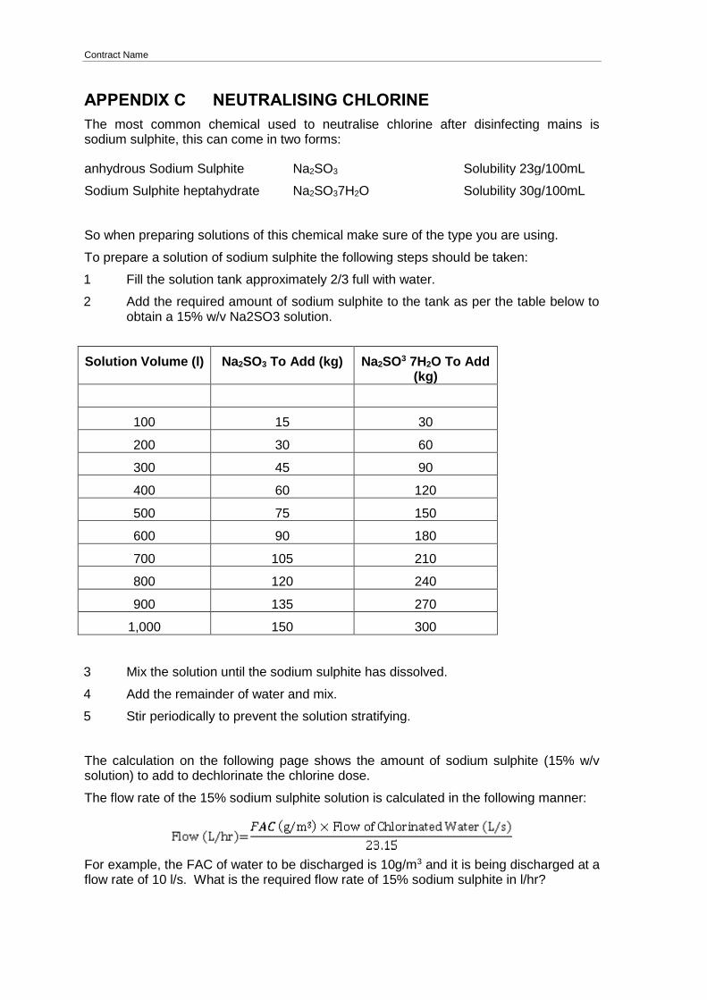
Contract Name
APPENDIX C NEUTRALISING CHLORINE
The most common chemical used to neutralise chlorine after disinfecting mains is sodium sulphite, this can come in two forms:
anhydrous Sodium Sulphite Na2SO3 Solubility 23g/100mL
Sodium Sulphite heptahydrate Na2SO37H2O Solubility 30g/100mL
So when preparing solutions of this chemical make sure of the type you are using.
To prepare a solution of sodium sulphite the following steps should be taken:
1 Fill the solution tank approximately 2/3 full with water.
2 Add the required amount of sodium sulphite to the tank as per the table below to obtain a 15% w/v Na2SO3 solution.
Solution Volume (l) Na2SO3 To Add (kg) Na2SO3 7H2O To Add (kg)
100 15 30
200 30 60
300 45 90
400 60 120
500 75 150
600 90 180
700 105 210
800 120 240
900 135 270
1,000 150 300
3 Mix the solution until the sodium sulphite has dissolved.
4 Add the remainder of water and mix.
5 Stir periodically to prevent the solution stratifying.
The calculation on the following page shows the amount of sodium sulphite (15% w/v solution) to add to dechlorinate the chlorine dose.
The flow rate of the 15% sodium sulphite solution is calculated in the following manner:
For example, the FAC of water to be discharged is 10g/m3 and it is being discharged at a flow rate of 10 l/s. What is the required flow rate of 15% sodium sulphite in l/hr?

Contract Name
A calibrated dosing pump will enable this flow to be achieved by adjusting the speed or stroke setting off a calibration chart.
A check on the treated water FAC level will ensure that the dose is adequate.
After 10 seconds contact time the FAC level should be close to 0.
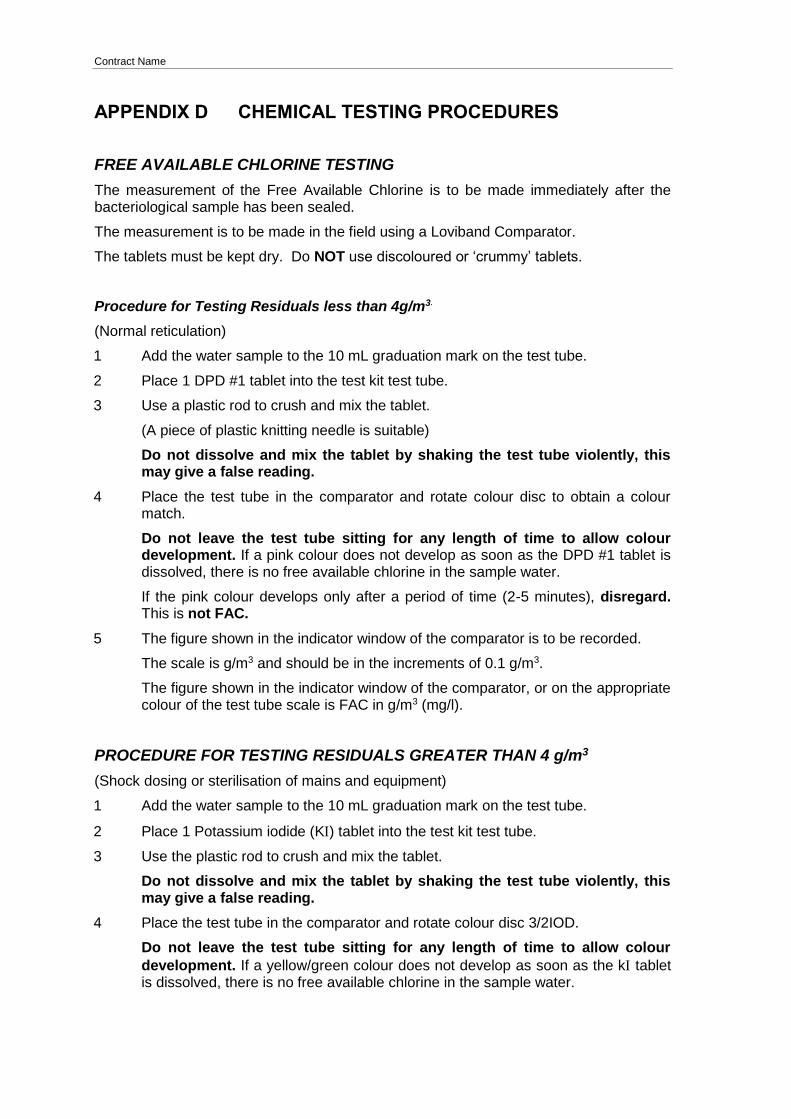
Contract Name
APPENDIX D CHEMICAL TESTING PROCEDURES
FREE AVAILABLE CHLORINE TESTING
The measurement of the Free Available Chlorine is to be made immediately after the bacteriological sample has been sealed.
The measurement is to be made in the field using a Loviband Comparator.
The tablets must be kept dry. Do NOT use discoloured or ‘crummy’ tablets.
Procedure for Testing Residuals less than 4g/m3.
(Normal reticulation)
1 Add the water sample to the 10 mL graduation mark on the test tube.
2 Place 1 DPD #1 tablet into the test kit test tube.
3 Use a plastic rod to crush and mix the tablet.
(A piece of plastic knitting needle is suitable)
Do not dissolve and mix the tablet by shaking the test tube violently, this may give a false reading.
4 Place the test tube in the comparator and rotate colour disc to obtain a colour match.
Do not leave the test tube sitting for any length of time to allow colour development. If a pink colour does not develop as soon as the DPD #1 tablet is dissolved, there is no free available chlorine in the sample water.
If the pink colour develops only after a period of time (2-5 minutes), disregard. This is not FAC.
5 The figure shown in the indicator window of the comparator is to be recorded.
The scale is g/m3 and should be in the increments of 0.1 g/m3.
The figure shown in the indicator window of the comparator, or on the appropriate colour of the test tube scale is FAC in g/m3 (mg/l).
PROCEDURE FOR TESTING RESIDUALS GREATER THAN 4 g/m3
(Shock dosing or sterilisation of mains and equipment)
1 Add the water sample to the 10 mL graduation mark on the test tube.
2 Place 1 Potassium iodide (K) tablet into the test kit test tube.
3 Use the plastic rod to crush and mix the tablet.
Do not dissolve and mix the tablet by shaking the test tube violently, this may give a false reading.
4 Place the test tube in the comparator and rotate colour disc 3/2IOD.
Do not leave the test tube sitting for any length of time to allow colour
development. If a yellow/green colour does not develop as soon as the k tablet is dissolved, there is no free available chlorine in the sample water.

Contract Name
If the yellow/green colour develops only after a period of time (2-5 minutes), disregard. This is not FAC.
5 The figure in the indicator window of the comparator is FAC in g/m3 (mg/l)
pH TESTING
pH plays an important role in the chlorine disinfection for water with regards to the formation of HOCl, the disinfecting “agent”. At pH greater than 8.0 very little HOCl is formed and thus the disinfecting capability of the chlorine is decreased. The pH can be affected mainly by water dissolving cement linings of new cast iron or steel pipes and disinfection of concrete lined reservoirs.
The pH can be tested using “pH tablets” – this can be purchased from a pool supplier) or an electronic pH meter. To use the pH tablets or electronic pH meter follow manufacturers instructions. Details of how to use the pH meter are shown below.
Equipment
1x pH meter
100mL pH 7.0 buffer
Procedure
1 Place the end of the pH probe into the pH 7.0 buffer.
2 Leave the meter in the buffer until the reading stabilises.
3 Calibrate the meter to 7.0 via the adjustment screw at the back of the meter.
4 The meter is now ready to use.
5 Dip the pH probe into the sample, read the value on the pH meter.
6 The meter should be re-checked every time a reading is taken.
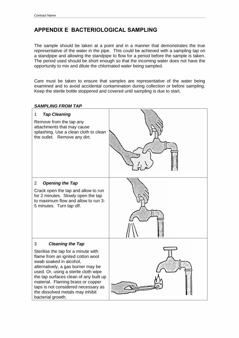
Contract Name
APPENDIX E BACTERIOLOGICAL SAMPLING
The sample should be taken at a point and in a manner that demonstrates the true representative of the water in the pipe. This could be achieved with a sampling tap on a standpipe and allowing the standpipe to flow for a period before the sample is taken. The period used should be short enough so that the incoming water does not have the opportunity to mix and dilute the chlorinated water being sampled.
Care must be taken to ensure that samples are representative of the water being examined and to avoid accidental contamination during collection or before sampling. Keep the sterile bottle stoppered and covered until sampling is due to start,
SAMPLING FROM TAP
1 Tap Cleaning
Remove from the tap any attachments that may cause splashing. Use a clean cloth to clean the outlet. Remove any dirt.
2 Opening the Tap
Crack open the tap and allow to run for 2 minutes. Slowly open the tap to maximum flow and allow to run 3-5 minutes. Turn tap off.
3 Cleaning the Tap
Sterilise the tap for a minute with flame from an ignited cotton wool swab soaked in alcohol, alternatively, a gas burner may be used. Or, using a sterile cloth wipe the tap surfaces clean of any built up material. Flaming brass or copper taps is not considered necessary as the dissolved metals may inhibit bacterial growth.
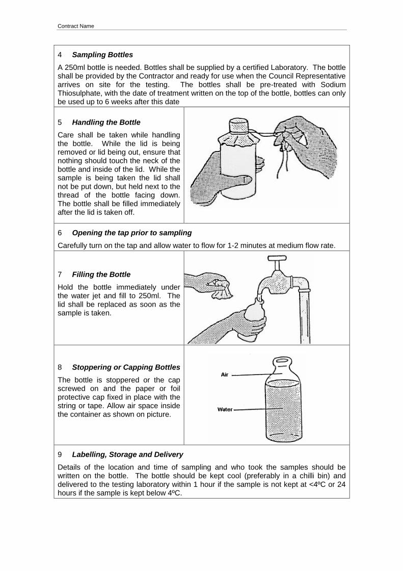
Contract Name
4 Sampling Bottles
A 250ml bottle is needed. Bottles shall be supplied by a certified Laboratory. The bottle shall be provided by the Contractor and ready for use when the Council Representative arrives on site for the testing. The bottles shall be pre-treated with Sodium Thiosulphate, with the date of treatment written on the top of the bottle, bottles can only be used up to 6 weeks after this date
5 Handling the Bottle
Care shall be taken while handling the bottle. While the lid is being removed or lid being out, ensure that nothing should touch the neck of the bottle and inside of the lid. While the sample is being taken the lid shall not be put down, but held next to the thread of the bottle facing down. The bottle shall be filled immediately after the lid is taken off.
6 Opening the tap prior to sampling
Carefully turn on the tap and allow water to flow for 1-2 minutes at medium flow rate.
7 Filling the Bottle
Hold the bottle immediately under the water jet and fill to 250ml. The lid shall be replaced as soon as the sample is taken.
8 Stoppering or Capping Bottles
The bottle is stoppered or the cap screwed on and the paper or foil protective cap fixed in place with the string or tape. Allow air space inside the container as shown on picture.
9 Labelling, Storage and Delivery
Details of the location and time of sampling and who took the samples should be written on the bottle. The bottle should be kept cool (preferably in a chilli bin) and delivered to the testing laboratory within 1 hour if the sample is not kept at <4ºC or 24 hours if the sample is kept below 4ºC.