Embed Size (px)
Citation preview
29 Bocam Park, Old Field Road, Pencoed, Bridgend CF35 5LJ. Phone: 01656 863794 Email: [email protected]
Drainage Strategy Report For:
Proposed Residential Development at:
Land off Heol Pentre Bach,
Gorseinon,
Swansea.
SA4 6TH
Prepared for:
V &C(SW)Properties Ltd
December 2017
2
REF: 7333
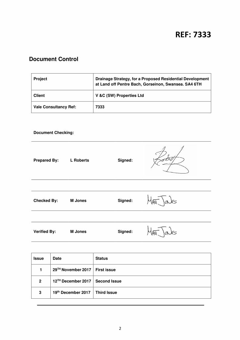
Document Control
Project Drainage Strategy, for a Proposed Residential Development
at Land off Pentre Bach, Gorseinon, Swansea. SA4 6TH
Client V &C (SW) Properties Ltd
Vale Consultancy Ref: 7333
Document Checking:
Prepared By: L Roberts Signed:
Checked By: M Jones Signed:
Verified By: M Jones Signed:
Issue Date Status
1 29TH November 2017 First issue
2 12TH December 2017 Second Issue
3 19th December 2017 Third Issue
3
CONTENTS
1. Introduction
2. Background
3. Proposed Foul Water Drainage (Concept)
4. Proposed Surface Water Drainage (Concept)
5.Discharge Method
6. Surface Water Drainage -Exceedance Flows
7. Pollution Prevention
8. Conclusion
AppendicesAppendicesAppendicesAppendices
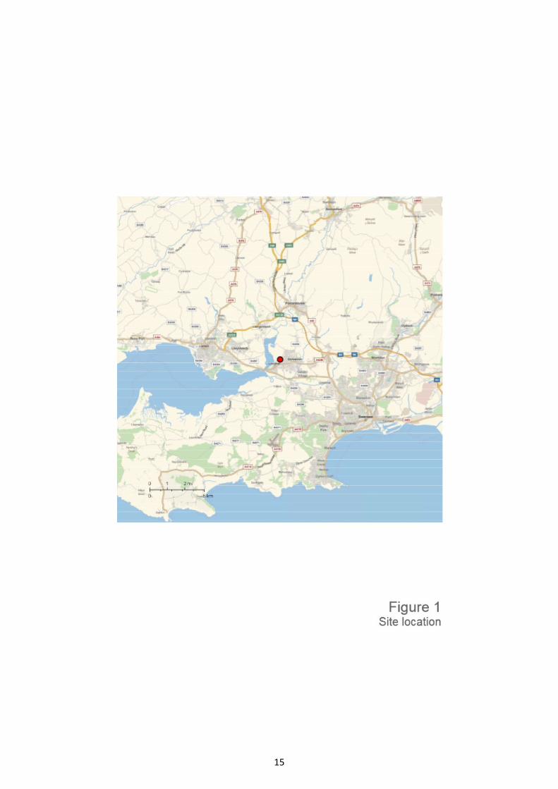
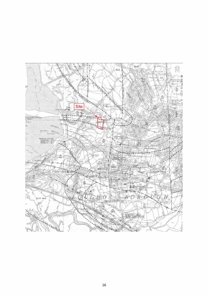
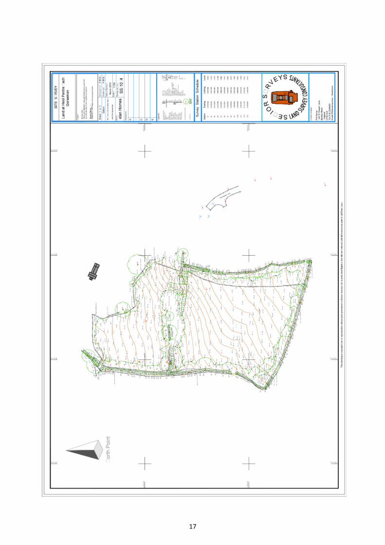
Appendix A Site Location Plan and Topographical Survey
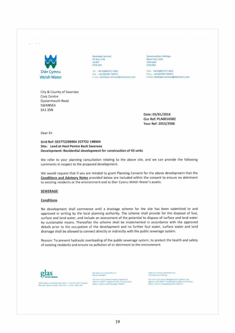
Appendix B Sewer Records, Correspondence
Appendix C Concept Drainage Layout
Appendix D Proposed Development Layout
Appendix E NRW Flood Maps
4
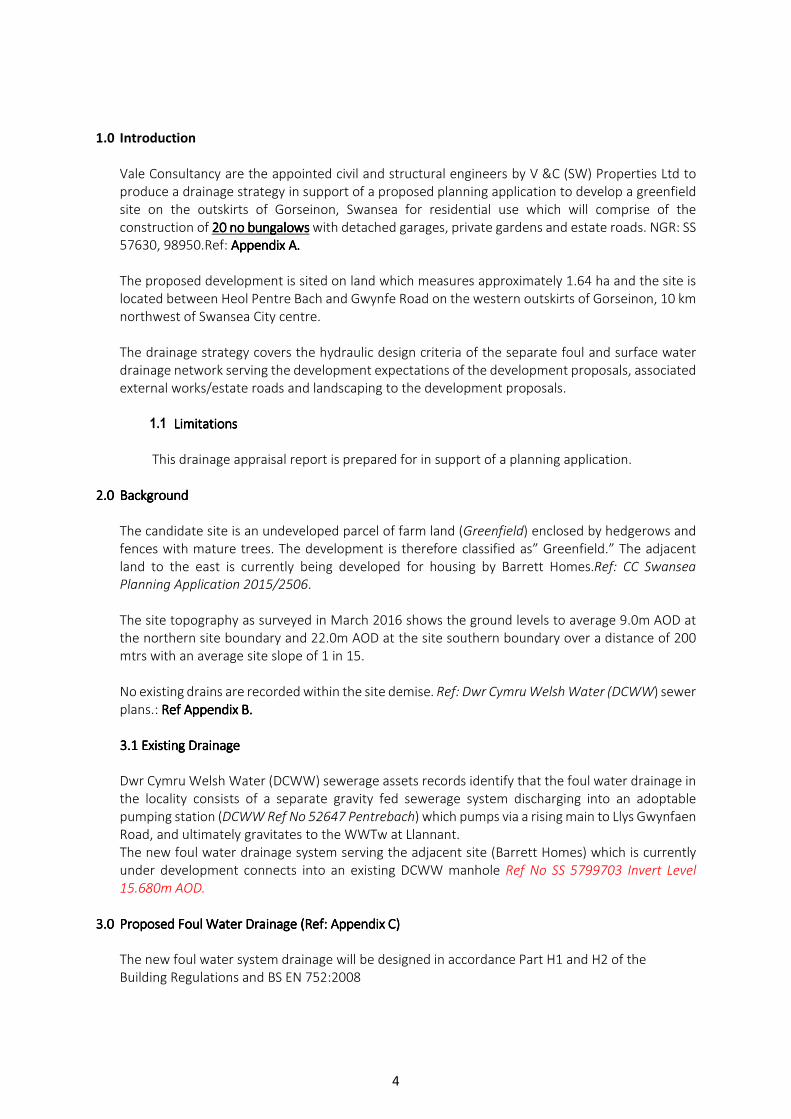
1.0 Introduction
Vale Consultancy are the appointed civil and structural engineers by V &C (SW) Properties Ltd to
produce a drainage strategy in support of a proposed planning application to develop a greenfield
site on the outskirts of Gorseinon, Swansea for residential use which will comprise of the
construction of 20202020 no bungalowsno bungalowsno bungalowsno bungalows with detached garages, private gardens and estate roads. NGR: SS
57630, 98950.Ref: Appendix AAppendix AAppendix AAppendix A....
The proposed development is sited on land which measures approximately 1.64 ha and the site is
located between Heol Pentre Bach and Gwynfe Road on the western outskirts of Gorseinon, 10 km
northwest of Swansea City centre.
The drainage strategy covers the hydraulic design criteria of the separate foul and surface water
drainage network serving the development expectations of the development proposals, associated
external works/estate roads and landscaping to the development proposals.
1.1 LimitationsLimitationsLimitationsLimitations
This drainage appraisal report is prepared for in support of a planning application.
2.02.02.02.0 BackgroundBackgroundBackgroundBackground
The candidate site is an undeveloped parcel of farm land (Greenfield) enclosed by hedgerows and
fences with mature trees. The development is therefore classified as” Greenfield.” The adjacent
land to the east is currently being developed for housing by Barrett Homes.Ref: CC Swansea
Planning Application 2015/2506.
The site topography as surveyed in March 2016 shows the ground levels to average 9.0m AOD at
the northern site boundary and 22.0m AOD at the site southern boundary over a distance of 200
mtrs with an average site slope of 1 in 15.
No existing drains are recorded within the site demise. Ref: Dwr Cymru Welsh Water (DCWW) sewer
plans.: Ref Appendix BRef Appendix BRef Appendix BRef Appendix B....
3.1 Existing Drainage3.1 Existing Drainage3.1 Existing Drainage3.1 Existing Drainage
Dwr Cymru Welsh Water (DCWW) sewerage assets records identify that the foul water drainage in
the locality consists of a separate gravity fed sewerage system discharging into an adoptable
pumping station (DCWW Ref No 52647 Pentrebach) which pumps via a rising main to Llys Gwynfaen
Road, and ultimately gravitates to the WWTw at Llannant.
The new foul water drainage system serving the adjacent site (Barrett Homes) which is currently
under development connects into an existing DCWW manhole Ref No SS 5799703 Invert Level
15.680m AOD.
3.03.03.03.0 Proposed Foul Water Drainage (Ref: Appendix Proposed Foul Water Drainage (Ref: Appendix Proposed Foul Water Drainage (Ref: Appendix Proposed Foul Water Drainage (Ref: Appendix CCCC))))
The new foul water system drainage will be designed in accordance Part H1 and H2 of the
Building Regulations and BS EN 752:2008
5
In the proposed scheme, no surface water drainage will be discharging into proposed foul water
drainage system.
The hydraulic design of the domestic water component generated by the development proposal
has been based on the current Code of Practice produced by The British Water Flows and Loads-
Sizing Criteria, Treatment Capacity for Sewage Treatment Systems, which is based on the
relationship between water usage and wastewater production. Adequate cover and protection will
be provided to the proposed foul water drainage system.
British Water Table of Loadings for Sewage Treatment Systems based on Per person/activity/day
for the classification and selection of the flowing classifications within the proposed building:
• Residential= 180 l/person /day (0.042 l/sec**)
The residential units with a peak flow multiple for sewage treatment plant of 6 DWF (Dry Weather
Flow) and 10% infiltration based on 4000 litres per dwelling per day (based on 3 persons/dwelling
200 litres per head per day): 0.046 litres/second: Sewers for Adoption 7TH Edition B5.1
Dwr Cymru Welsh Water wastewater profile assessment use the design figure per capita return
to sewer flow of 180l/hd/day design standard.:0.042 l/sec**
Therefore, applying the same maxim to the proposed development.
3.1 Design Flow Rates from Proposed Development
Category of Building: Detached Building of Mixed use
Wastewater Flows based on:
• No of residential units (bungalows) 20 No x 0.042 l/sec= 0.84 l/sec
Total daily flow = 72,576 litres per day (0.84 l/sec)
Therefore, the total daily foul water flow emanating from the building based on 90% of
cold water demand is: 72,576 l/day x 0.90 =65,318 l/day (0.76. l/sec) **This figure is a
design peak flow rate and not an average water usage, and represents the peak flow rate
from a number of appliances.
65,318 l/day total flow / 1000 = 65 cubic metres per day effluent discharge to public
sewerage system
Design Note:
Peak flow rate may also be determined by the application of a diurnal wastewater flow
pattern resulting in a variable peak factor so that attenuation and diversification effects
tend to reduce peal flow, and so the ratio of peak to average flow generally decreases from
top to bottom of the new drainage network.
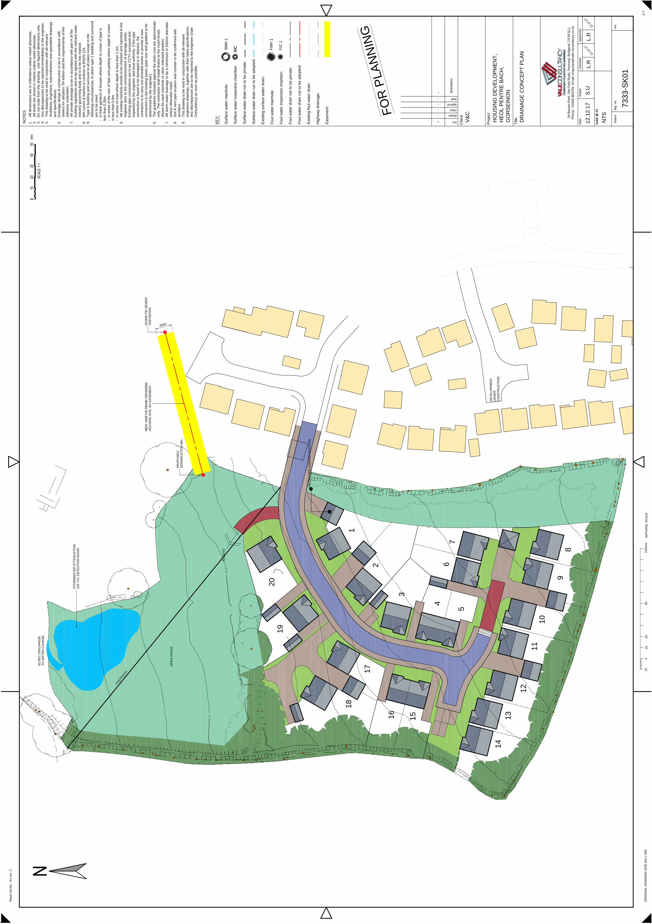
3.2 Foul Water Drainage (Ref: Appendix D.)
6
After site clearance, a new gravity drainage system serving the development proposals will
be constructed. The design options for the proposed foul water layout serving the
development expectations are as follows:
Design ProposalDesign ProposalDesign ProposalDesign Proposal
Given that the site topography slopes from the southern boundary (Av 22.0 m AOD) to the
northern eastern boundary new drainage the layout would be a total gravitational system
discharging into a Section 104 demarcation manhole prior to passing forward offsite into
DCWW public sewerage, and the identified point of connection would be MH Ref No
SS5799703 (The adjacent Barrett Homes development which also takes benefit from this
point of connection) the drain would be routed offsite in a vested easement/highway as Part Part Part Part
of the route of the of the route of the of the route of the of the route of the site drainage site drainage site drainage site drainage would require the crossing of third party land (would require the crossing of third party land (would require the crossing of third party land (would require the crossing of third party land (Elan Homes).Elan Homes).Elan Homes).Elan Homes).
Ref: AppendixRef: AppendixRef: AppendixRef: Appendix C.C.C.C.
Design noteDesign noteDesign noteDesign note:::: uplifting site levels to the lower part of the site to promote a total gravitational
drainage system would be cost prohibitive and have an impact on the north and west
boundary condition.
Any offsite work regarding drainage will involve the application to City and County of
Swansea for a license under Section 50 of The New Roads50 of The New Roads50 of The New Roads50 of The New Roads and Street Works Act 1991and Street Works Act 1991and Street Works Act 1991and Street Works Act 1991 to
excavate a trench to place apparatus (sewer pipe)
The construction of the new carrier drains would provide self-cleansing velocity for the
relative pipe diameter as per BSEN 752:2008, Building Regulation 2010 Part H1 and H2
The proposed foul water layout serving the development expectations will be based on
Sewers for Adoption 7TH Edition where the offsite gravity drain will be a 150150150150mmmmmmmm diadiadiadia
drain from a demarcation chamber constructed at the site boundary. The lateral drain will
offered for adoption under the provisions of a Section 104 Water Industry Act 1991 (WIA91).
The legal right of connection under a Section 106 of the WIA91 will not exist until a Section
104 Agreement is in place for the lateral drain.
4.04.04.04.0 Proposed Surface Water DrainageProposed Surface Water DrainageProposed Surface Water DrainageProposed Surface Water Drainage (Ref: Appendix D)
The Flood and Water Management Act 2010 establishes a Sustainable Drainage Systems Approving
Body in Unitary or County Councils. This body must approve drainage systems in new
developments and re-developments before construction begins. Therefore, to reduce the flood
risk mitigation and impact of surface water runoff from the development on flood risk, this will be
based on limiting the peak runoff rate and runoff volume for extreme events for the 1:100-year
return period plus climate change. In aiming to replicate greenfield runoff rates for extreme
events, this will help to ensure that flood risk associated with the receiving watercourse and not
increased by the development proposals.
The site is former agricultural undeveloped land and therefore classified as “Greenfeild”Greenfeild”Greenfeild”Greenfeild”....
7
There ae no bodies of surface water within the site boundary. There exists an ordinary watercourse
just beyond the site northern boundary where the ground level is lowest and the development
could take benefit off by discharging a restricted surface water flow. This would need consent and
approval of the Lead Local Drainage Authority (LLDA) City and County of Swansea.
The strormwater runoff volume from the site post development will be limited to the greenfield
runoff volume for all event frequencies.
Consequently, it is proposed that a managed and restricted the discharge of the additional
predicted volume (100year 6 hr event) as a result of runoff due to the development, which will
outfall into the existing receiving watercourse at a permissible discharge via a Hydrobrake flow
control at a rate of 15151515 l/l/l/l/secsecsecsec, , , , with onsite attenuation measures.
The method used for calculating the Greenfield peak flow runoff rate is the approach identified in
IH124 Flood estimation for Small Catchments
The following receptors have been considered for surface water runoff in order of preference.
1. Discharge by infiltration into groundDischarge by infiltration into groundDischarge by infiltration into groundDischarge by infiltration into ground— NotNotNotNot ApplicableApplicableApplicableApplicable---- percolation test results to be carried outpercolation test results to be carried outpercolation test results to be carried outpercolation test results to be carried out in the in the in the in the
ssssite Investigation workite Investigation workite Investigation workite Investigation work ((((Ref Geo Consult dated 24 November 2017) identified poor Ref Geo Consult dated 24 November 2017) identified poor Ref Geo Consult dated 24 November 2017) identified poor Ref Geo Consult dated 24 November 2017) identified poor infiltration resultsinfiltration resultsinfiltration resultsinfiltration results....
2. Discharge into open surface water bodyDischarge into open surface water bodyDischarge into open surface water bodyDischarge into open surface water body———— Applicable Applicable Applicable Applicable with with with with restricted flow control.restricted flow control.restricted flow control.restricted flow control.
3. Discharge into surface water sewerDischarge into surface water sewerDischarge into surface water sewerDischarge into surface water sewer---------------------------- Not Not Not Not Applicable.Applicable.Applicable.Applicable. No No No No Sewers AvailableSewers AvailableSewers AvailableSewers Available
4. Discharge into combined sewerDischarge into combined sewerDischarge into combined sewerDischarge into combined sewer. — Not Not Not Not Applicable. Applicable. Applicable. Applicable. Managed discharge to Managed discharge to Managed discharge to Managed discharge to watercourse.watercourse.watercourse.watercourse.
Discharge to a foul drainage will not be permitted.
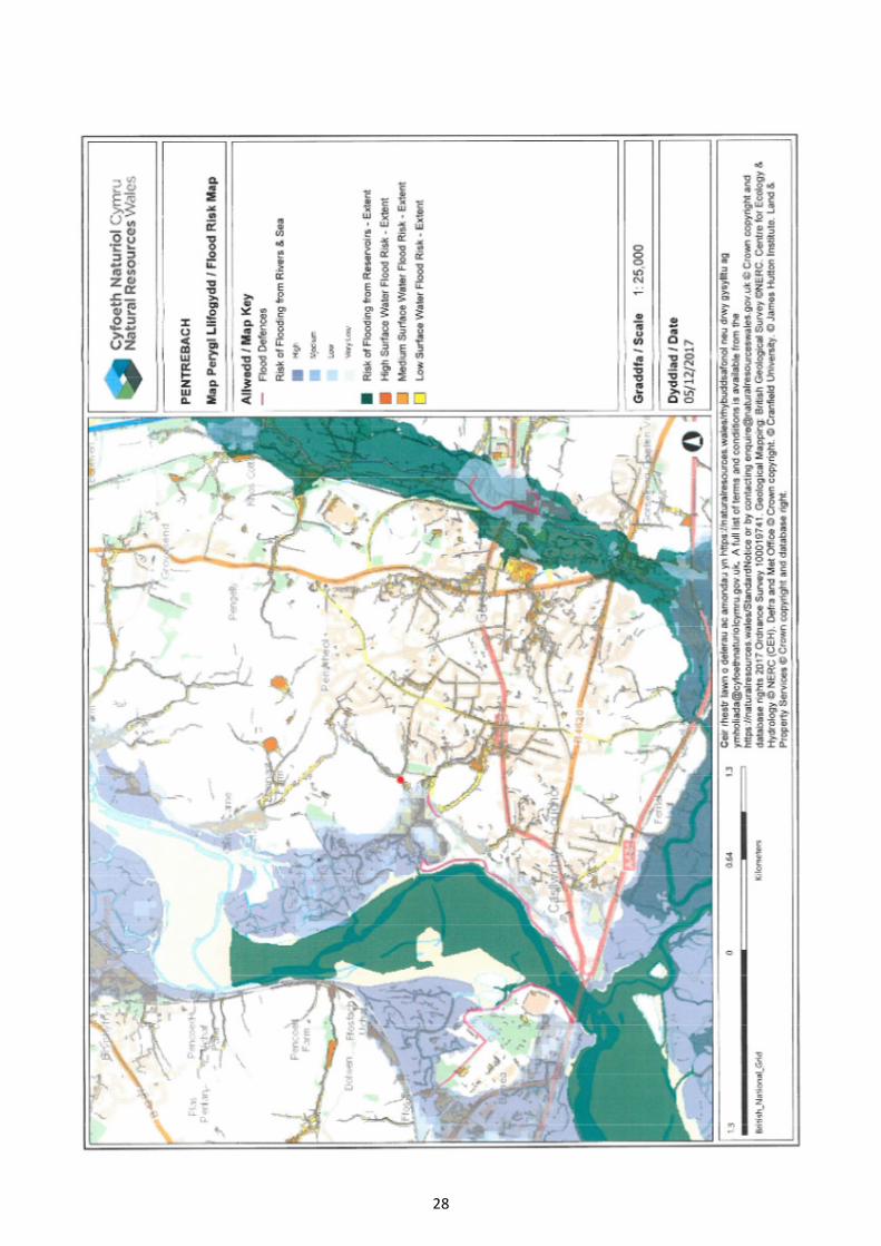
4.1 Background
Vale Consultancy have undertaken a qualitative appraisal of flood risk on site, as required under PPW
TAN 15 and based on the findings of the sourced information the site is outside the NRW Flood Zone
1 (Zone A) envelope and therefore unaffected by the fluvial 1 in 100 and 1 in 1000-year flood events.
A stage 3 FCA will not be required. Ref: Appendix E.
• Flooding from Sea: considered low due to proximity of the Lougher Estuary 500m
to the west of the site and the site elevation 9m AOD to 22.0m AOD.
• Fluvial Flood from rivers: considered low due to the stretch of the River Lougher
west of the site which is tidal and the mean high water line of the main river
channel is approximately 500m from the site.
• Pluvial Flooding: considered low as the sites slopes at an average gradient of 1 in
15 with a proposed housing to the east and open field beyond to the west
overland flow would be channelled by Heol Pentre Bach and Gwynfe Road.
• Flooding from Groundwater: is considered low as the site investigation was
determined that the ground was found to be impermeable.
• Flooding from Sewers: indicates that there is a risk of flood from surface water
sewers with a high probability for escape from the 1 in 30-year return period from
the sewers in Heol Pentre Bach, therefore the proposed house will be set above
the adjacent Heol Pentre Bach.
8
• Flooding from Reservoirs, Canals and other artificial Water Bodies: is considered
low as there are no reservoirs, canals or artificial water bodies the could impact
the site in the event of breach/failure should occur.
4.2 Site Characteristics-Pre-Development
The pre-developed site surface consists mainly of former agricultural undeveloped farmland. A
detailed site investigation has been carried out by Geo Consult and part of the site investigation
soakaway infiltration/percolation tests consistent and in accordance with BRE Digest 365, concluded
that the ground was impermeable and would not support the use of infiltration as a method of surface
water disposal.
4.3 Post -Development Surface Water Drainage: Appendix C
The design approach of the post development surface water drainage strategy will be based on the
flowing recommendations contained within the following publications:
The Welsh Government Publication Titled:” Recommended non-statutory standards for sustainable
drainage (SUDs) in Wales -designing, constructing, operating and maintaining surface water drainage”
systems published in January 2017,G2:26: Runoff rate for previously undeveloped sites “Greenfield”
“should be measured against the performance of the pre-developed site.
Whilst accommodating for the appropriate design storm scenarios for the site catchment area
including climate change and in series incrementally storm profiles to reduce peak flow rate, volume
of runoff and reduce pollution, through effective control of runoff at source by the principles of
Sustainable Urban Drainage (SUDs) techniques. The site will store, on site, the peak discharge as
appropriate and discharge a restricted flow to the onsite ordinary watercourse.
4.4 4.4 4.4 4.4 Urban Urban Urban Urban Surface WSurface WSurface WSurface Water Managementater Managementater Managementater Management
The SUDs selection criteria have been determined for a drainage solution best suited to the proposed
land end use of the area under consideration and draining to the watercourse. Which is a combination
of block paving, grasscrete for the car parking lay down areas.
• Soakaways Soakaways Soakaways Soakaways
Soakaway percolation tests are to be undertaken to BRE 365 as part of the site investigation work, and
the ground infiltration rate was found to be unsuitable for a soakaway method of surface water
disposal. The surface water runoff from the new building will be by a piped connection to the new
infrastructure storm water drainage system and exceedance overflow channelled within the estate
roads, for extreme storm events. Appendix DAppendix DAppendix DAppendix D
• Block Paviours.
Block paving would offer a has a 40% run-off retardance to the time of entry into the drainage
system would offer an improved the hydraulic performance in mitigating the impact of surface water
run-off.
9
� Attenuation Storage
To mitigate the impact of site urbanisation the surface water drainage system for the development
will be designed based on the principles of CIRIA SuDS Manual C753, and to achieve the estimated
permissible discharge rate attenuation storage will be required. A storage volume will be
determined/verified at the detail design stage which will accommodate runoff during the 1 in 100 year
plus 30% climate change. The attenuation storage is based on storage within two possible options and
the preferred solution would be to take advantage of the natural topography of the site, which are
described as follows:
� Detention Basin (Preferred Option): which would be located at the lowest part of the site,
this form of attenuation is normally a dry basin providing temporary storage and controlled
release of detained runoff. They are normally vegetative depressions that are mainly dry,
except during and immediately after storm events. It can be designed and engineered with a
small permanent pool of water at the outlet to help prevent re-suspension of sediment
particles because of high intensity storms and provide enhanced water quality treatment for
frequent storm events. The basin would be design as an online storage facility with a flow
control device within the outlet structure prior to the passing forward to the receiving
ordinary watercourse. Key design criteria: minimum lenth:width ratio 2:1, Maximum side
slopes 4:1,for maintenance and safety reasons, and frequent maintenance required (litter
removal ,inlet/outlet cleaning, vegetation management).
� Retention Pond: which would be located at the lowest part of the site, this form of
attenuation would have a permanent pool of water which would remain throughout the year
(less evaporation), with the storage being provided in the freeboard above the permanent
water level. The pond would become an amenity/aesthetic feature with good community
acceptability and support emergent and submerged aquatic vegetation along the pond
shoreline, with high ecological potential. Key design criteria:length:width ration 3:1and 5:1,
minimum depth of open water area 1.2 maximum depth of pool 2m, side slopes 1:3min and
frequent maintenance as per detention basin plus sediment monitoring and removal when
required.
� Rainwater Harvesting
The attenuation benefits provided using rainwater harvesting are limited and would be only
realised when the tanks were not full in addition a cost benefit analysis would need to be
considered regarding the viability of the scheme.
.
5.05.05.05.0 Discharge MethodDischarge MethodDischarge MethodDischarge Method
.
5555....1111 Proposed Post Development Surface Water RunoffProposed Post Development Surface Water RunoffProposed Post Development Surface Water RunoffProposed Post Development Surface Water Runoff
10
The approach is to provide a managed discharge of surface water runoff with attenuation
storage provided by below ground geo-cellular storage system.
The estimated runoff rates and volumes from the proposed impermeable catchment areas
have been calculated using the Modified Rational (Wallingford) Method. This method
allows estimation of the amount of runoff likely to be generated from the development
proposals from a range of storm returns. Rainfall depths for various storm return periods
have been produced using the Micro- Drainage Windes (Version 2015.1. Depth –
Frequency-Duration) modelling functions have been used to calculate rainfall intensities
for a specific return period. The MRM uses the following equation to calculate peak runoff
rate from a given area:
Q = 2.78 Cv CR i A
Where:
CV = Volumetric Runoff Coefficient
Cr = 1.3 (Routing Coefficient)
I = Rainfall Intensity (mm/hr)
A = Area.
2.78 = Coefficient which accounts for the difference in units used for inputs and outputs
of the equation.
The variable CV is a coefficient that describes the proportion of rainfall appearing on the
surface water drainage system, CR is a routing coefficient added to the Rational Method
to represent runoff characteristics of a particular site or area in a more accurate manner.
The Rational Method is recognized as oversimplifying the rainfall runoff process but it
considered sufficiently accurate for runoff estimations for small catchment contributing
areas. The main assumption being that the rainfall occurs at a uniform intensity for a
duration equal to the time of concentration of the catchment and that the rainfall occurs
over the entire catchment area, with the rainfall return period being the same as the
runoff return period.
5.2 Design Approach
� Existing site pre-development area = 1.64ha
Existing Site Catchment Area and Runoff =15 l/sec
Re-developed are to be determined
ProposedProposedProposedProposed RunoffRunoffRunoffRunoff = Based on a permissible discharge rate of = Based on a permissible discharge rate of = Based on a permissible discharge rate of = Based on a permissible discharge rate of 15151515 l/secl/secl/secl/sec
A surface water discharge with a controlled rate A surface water discharge with a controlled rate A surface water discharge with a controlled rate A surface water discharge with a controlled rate of of of of 15151515 l/sec enterl/sec enterl/sec enterl/sec entering theing theing theing the public sewerpublic sewerpublic sewerpublic sewer withwithwithwith
below ground storage for the 1 in 100below ground storage for the 1 in 100below ground storage for the 1 in 100below ground storage for the 1 in 100----year (1.0%) storm event + 30% climate change for year (1.0%) storm event + 30% climate change for year (1.0%) storm event + 30% climate change for year (1.0%) storm event + 30% climate change for
the rethe rethe rethe re----developed developed developed developed area.area.area.area. ActualActualActualActual storagestoragestoragestorage volumevolumevolumevolume of the attenuation facility of the attenuation facility of the attenuation facility of the attenuation facility totototo be confirmed be confirmed be confirmed be confirmed
during detail drainage designduring detail drainage designduring detail drainage designduring detail drainage design
5.3 Three annual probabilities merThree annual probabilities merThree annual probabilities merThree annual probabilities merit specific consideration: 100%, it specific consideration: 100%, it specific consideration: 100%, it specific consideration: 100%, 3.33% and 1%3.33% and 1%3.33% and 1%3.33% and 1%
11
The 100% annual probability100% annual probability100% annual probability100% annual probability (once in one-year event) is the highest probability event to be
specifically considered to ensure that the flows to the ordinary watercourse are tightly
controlled for these frequent events
The 3.33% annual probability3.33% annual probability3.33% annual probability3.33% annual probability (1 in 30-year event) is of importance because of the linkage
with the level of service requirements of Sewers for Adoption that requires surface water
sewers can convey
this storm event within the drainage network without causing flooding to any part of the
site.
The 1% annual probabilit1% annual probabilit1% annual probabilit1% annual probabilityyyy (1 in 100-year event) has been selected since it represents the
boundary between high and medium risk of fluvial flooding defined in TAN 15 and
recognises it is not practicable to fully limit flows for the most extreme storm events. Also
during storm events of this magnitude the capacity of the surface water drainage system
may be inadequate, however the. floor levels of the proposed buildings will be flood free.
Flood flows up to 1% annual probability are contained within the site and will have little
material impact in terms of nuisance and damage. Overland flood flows within the site
have been assessed for the short high intensity rainfall events of between 15 mins and 1-
hour duration.
5.4 5.4 5.4 5.4 Surface Water Drainage Strategy (Ref: Appendix D)Surface Water Drainage Strategy (Ref: Appendix D)Surface Water Drainage Strategy (Ref: Appendix D)Surface Water Drainage Strategy (Ref: Appendix D)
As part of the new drainage strategy we are proposing the following:
• The system is designed not to flood any part of the site in a 1:30 year return period design
storm.
• The external catchment area of the access road/car parking bays will discharge by a system
of line drains and gullies into the new surface water network via an on-line suitably sized
pollution screening unit
• The development drainage system will be a managed gravity system with a vortex flow
(Hydrobrake) control set at and agreed permissible discharge rate with an online storage
system sited at the lowest part of the site. with the access maintenance track, the system
will be privately managed.
During the detailed design process, the proposed network will be simulated by the industry
standard drainage design computer software, Micro Drainage - WinDes. WinDes applies
the MRM, analysing each pipe on an individual basis for all storm durations between 15
and 1440 mins (1 day)
Assumptions:
• Design Criteria site with average ground slope less than 1%
• Global time of entry 5 mins
• Minimum velocity 0.75m/sec
• All roof areas and hardscaping to be 100% impermeably
• Hydraulic pipe roughness 0.6 Ks.
Part H of the Building Regulations and current best practice requires a sequential approach
for the disposal of surface water and requires the first choice of surface water disposal to
be discharge to infiltration systems where practicable (Ref 4.0 Point 1).
12
6.06.06.06.0 SuSuSuSurface Water Drainage rface Water Drainage rface Water Drainage rface Water Drainage –––– Exceedance FlowsExceedance FlowsExceedance FlowsExceedance Flows
In line with the design criteria of dealing with exceedance flows the proposed buildings will not
flood for storm events with a return period grater that 100 years plus climate change.
In accordance with best practice (CIRIA C635 Designing for Exceedance), flood waters from
storm events that exceed the design storm of 100years +cc will be channelled toward the lower
areas of soft landscaping within the site boundary. The proposed network modelling results
based on the Simulation Criteria for a 100-year storm return period for a range of storm
durations with the network at pipe full capacity, will indicate the points of storm water escape
from the proposed drainage network.
The exceedance overland surface conveyance of the flood pathways (default pathways) are
directed by design to effectively convey exceedance flow away from the buildings to areas in
the development low spots where temporary storage can be incorporated, this can be achieved
by the relatively minor detail of kerb heights.
7.07.07.07.0 Pollution PreventionPollution PreventionPollution PreventionPollution Prevention
Water Quality and Treatment Stages
The proposed surface water drainage system will improve the water quality from the
development proposals, entering the public surface water sewer which ultimately outfalls to
the ordinary watercourse which would have a degree of environmental sensitivity. This will be
done by using a treatment chain where each subsequent system within the proposed drainage
network is treated to improve water quality.
Infiltration drainage methods are unsuitable for this development and therefore treatment of
surface water prior to entering the ground water has not been considered.
The surface water treatment stage will depend on the potential hazards on the site and the
sensitivity of the receiving water body to pollution.
CatchmenCatchmenCatchmenCatchment: Roof WaterRoof WaterRoof WaterRoof Water Hazard LevelHazard LevelHazard LevelHazard Level: LowLowLowLow
CatchmenCatchmenCatchmenCatchment: Access Road,Access Road,Access Road,Access Road, Car ParkCar ParkCar ParkCar Park (less than 50 spaces)(less than 50 spaces)(less than 50 spaces)(less than 50 spaces), , , , ExternalsExternalsExternalsExternals Hazard LevelHazard LevelHazard LevelHazard Level: LowLowLowLow
Roof water is considered low risk and therefore zero treatment is required.
8.0 Conclusions
The proposal to re-develop the site would consist of a surface water management strategy with an
agreed limiting discharge passing forward into the ordinary watercourse routed in site demise. The
preferred method would be a normally dry Detention Basin as sufficient space is available within the
undeveloped part of the site.

13
The proposed surface water drainage scheme will ensure no increase in runoff over the lifetime of the
development.
The site will take benefit of the existing DCWW foul water sewer adjacent to the Elan Homes
development which would involve crossing third party land.Therfore, early stage
negotiations/agreements with third parties will need to be secured prior to the development
proceeding.
The development drainage will remain separate until the confluence stand-off manhole Ref MHC3
Inquiries with City and County of Swansea highway have confirmed that the estate roads serving the
Elan Homes development will be privately managed with NO Section 38 HA 90 adoption agreementNO Section 38 HA 90 adoption agreementNO Section 38 HA 90 adoption agreementNO Section 38 HA 90 adoption agreement
envisaged. It therefore follows as the candidate site under consideration requires access through the
Elan Homes development estate roads that similar arrangement of private estate roads management
will be required for the V &C development.

14
Appendix A
Site Location Plan and Topographical Survey
15
16
17

18
Appendix B
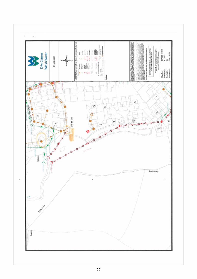
Sewer Records and Correspondence with DCWW
19
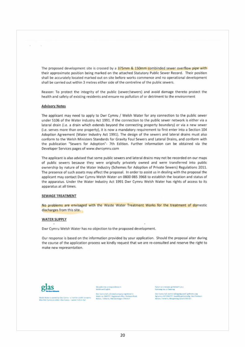
20

21
22

23
Appendix C
Drainage Concept
(Revised Master Plan 5th December 2017)
RS
1
7
.
0
1
7
.
0
1
6
.
0
16.0
15.0
1
5
.
0
1
4
.
0
2
2
.
0
2
1
.
0
2
0
.
0
2
0
.
0
1
9
.
0
1
9
.
0
13.0
1
8
.
0
1
8
.
0
9.0
12.0
1
2
.
0
11.0
1
0
.
0
1
2
3
4
5
6
7
8
9
10
11
12
13
14
15
16
17
18
19
22
.7
8
13.0
13.0
12.0
20
DE
VE
LO
PM
EN
T
UN
DE
R
CO
NS
TR
UC
TIO
N
RE
LO
CA
TE
D G
AR
AG
E P
OS
IT
IO
N
OP
EN
S
PA
CE
F
O
O
T
P
A
T
H
AC
CE
SS
6
0
0
0
NE
W 150Ø
F
W D
RA
IN
C
RO
SS
IN
G
HO
US
IN
G S
IT
E. 6m
E
AS
EM
EN
T.
DC
WW
F
W S
EW
ER
SS
57997003
PR
OP
OS
ED
DE
MA
RC
AT
IO
N M
H.
5L/S
EC
D
IS
CH
AR
GE
TO
W
AT
ER
C
OU
RS
E.
ST
OR
MW
AT
ER
A
TT
EN
UA
TIO
N.
100 +
CC
D
ET
EN
TIO
N B
AS
IN
.
KE
Y:
Surface w
ater m
anhole:
Surface w
ater inspection cham
ber:
Surface w
ater drain run to be private:
Surface w
ater drain run to be adopted:
Existing surface w
ater drain:
Foul w
ater m
anhole:
Foul w
ater inspection cham
ber:
Foul w
ater drain run to be private:
Foul w
ater drain run to be adopted:
Existing foul w
ater drain:
Highw
ay drainage:
Easem
ent:
SIC
FM
H 1
SIC
FIC
1
SM
H 1
V&
C
HO
US
IN
G D
EV
ELO
PM
EN
T,
HE
OL P
EN
TR
E B
AC
H,
GO
RS
EIN
ON
DR
AIN
AG
E C
ON
CE
PT
P
LA
N
12.12.17
S.U
L.R
1
2
.
1
2
.
1
7
L.R
1
2
.
1
2
.
1
7
NT
S
733
3-S
K0
1
-
-
-
-
-
-
sca
le
@
A
1
-
-
-
-
-
-
NO
TE
S
sca
le
@
A
1
00mm
1020
3040
50
SCAL
E 1:1
OR
IG
IN
AL
D
RA
WIN
G S
IZ
E 8
41
x 5
94
10
10
02
0N
AT
UR
AL
S
CA
LE
50
10
0m
m
Sh
ee
t A
CA
D - A
1 re
v. C
dra
wn
sta
tu
sd
rg
. n
o.
da
te
Title
re
v.
ch
ecke
da
pp
ro
ve
d
Pro
je
ct
apprvd.
rev.
drawn
chkd.
date
de
scrip
tio
n
Clie
nt
29 B
ocam
P
ark, O
ld F
ield R
oad, P
encoed, B
ridgend C
F35 5LJ.
Phone: 01656 863794 E
mail: enquiries@
vale-consultancy.co.uk
F
O
R
P
L
A
N
N
IN
G
N1.
All dim
ensions are in m
illim
etres unless noted otherw
ise.
2.
All levels are show
n in m
etres unless noted otherw
ise.
3.
Do not scale from
the draw
ing. U
se figured dim
ensions only.
4.
Any discrepancies to be reported im
mediately to the engineer.
5.
This draw
ing to be read in conjunction w
ith all relevant
Architects, engineers, subcontractors and specialists draw
ings
and specifications.
6.
Drainage design &
construction to be in accordance w
ith
sew
ers for adoption 7th edition and the requirem
ents of the
statutory undertaker.
7.
All private drainage to be in accordance w
ith part H
of the
building regulations and to be agreed w
ith the relevant w
ater
industry governing body and is to be kite m
arked.
8.
MH
covers &
fram
es to conform
to B
SE
N 124.
9.
Type S
bedding and surround to all pipes except in the
follow
ing circum
stances, in w
hich type Z
bedding and surround
are to be used:
-In back gardens of houses w
here depth to crow
n of pipe is
less than 0.35m
.
-In areas of the rear of flats and parking w
here depth to crow
n
is less than 0.9m
.
-In areas of road w
here depth is less than 1.2m
.
5.
All existing m
onhole inverts to be checked and reported to the
engineer prior to the com
mencem
ent of drainage w
orks.
Existing pipe connections are to be C
CT
V surveyed and
inspected by the engineer and local authority. If the pipe
connection is found to be dam
aged or in distress, the
contractor is to carry out rem
edial w
orks or provide a new
connection to the existing sew
er (pipe size and gradient to be
determ
ined by the engineer).
6.
The gradients indicated against the drain runs are approxim
ate
only. T
he contractor shall install drains to the invert levels
show
n for each m
anhole or other indicated position.
7.
All storm
w
ater drainage to be a m
im
im
um
of 150m
m diam
ater
unless otherw
ise noted.
8.
Soil &
vent pipe location and num
ber to be confirm
ed w
ith
architect.
9.
This draw
ing to be read in conjunction w
ith all relevant
engineers draw
ings, together w
ith their latest specifications.
Any discrepancies are to be reported to the engineer (V
ale
Consultancy) as soon as possible.

25
Appendix D
Proposed Development Layout
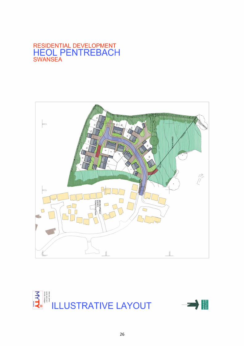
26

27
Appendix E
NRW Flood Maps
28