Embed Size (px)
Citation preview

AIVC 11715 Proc. CIBSE A: Building Serv. Eng. Res. Techno/. 19(4) 187-194 (1998) Printed in Grear Britain B487
Summary Below-ground srrucrures provide special challenges to the dC$igner of drainage systems, particularly if odour ingress is co be prevented to generally accepted standards. Ir is insufficient to rely
on entrained airflow co ensure char rhe network is generally at below atmospheric pressures; fan-assisted venting is often required. Transient propagation as a resulr of both system appliance discharge and the
operation of a fun-assisted vent system needs to be analysed ro avoid system failure. This paper presents rhe necessary solution ro the governing St Venant equations to allow sys\em simulation. The basis for a numerical simulation is presented and the boundary conditions particular to chis class of insrallarion are identified.
Drainage ventilation for underground structures I: Transient analysis of operation
J A Swaffield BSc MPhil PhD MRAeS FIWEM MCIBSE and G B Wrightt MEng PhD Department of Building Engineering and Surveying, Heriot-Watt University, Riccarron, Edinburgh EH14 4AS
Received 13 January 1998, in final form 27 May 1998
List of symbols
A 14 Coefficients in fan pressure-flow characteristic c Acoustic velocity or wave propagation speed in air
(m s-1) D Duct or fan diameter (m) f Friction factor K Loss coefficients at fan manifold to represent flow bal
ancing dampers or at an air admittance valve diaphragm KminMinimum loss through an air admittance valve when the
diaphragm is fully lifted K
14 Collected known terms at time t-l:lt in a Method of
Characteristics solution N Fan rotational speed (rad s-1) p Air pressure (N m-2) Q Air flow (m3 s-1) Q; Air flow in pipe i (m3 s-l) t Time(s) u Air flow velocity (m s-1) V Air volume enclosed in sump or holding tank (m3)
w Pressure change due to appliance discharge (Pa) x Distance from duct entry (m) l:lp Pressure rise across fan (N m-2) l:lt Time step governed by Courant Criterion (s) l:lx Inter-node distance (m) y Ratio of specific heat capacities p Air density (kg m-3)
Subscripts
0 Air conditions at time zero at atmospheric pressure I Conditions at fan boundary 1-3 Duct identification atm Atmospheric conditions ex Conditions at exit from a duct f Fan conditions m Air ingress volume P Calculation node point at location x and time t in a
Method of Characteristics solution ps Pump sump R,S Node points l:lx upstream and downstream of the calcula
tion position in a Method of Characteristics solution at time t-l:lt.
ref Fan reference conditions
tNow with Montgomery Warson, Manchester.
vent Flow through vent connection wat Water volume
Superscripts
t, t-l:lt Time
I Building drainage vent system operation
The prevention of odour ingress into habitable space through sanitary appliance connections has been a design prerequisite for building drainage systems from Victorian times. The development and acceptance of the trap seal allowed the drainage system to be effectively isolated from the internal spaces of the building. The design of the ventilation pipework to ensure that these trap seals were retained despite the air pressures generated within the drainage network as a result of the water flows following appliance discharge became, and to some ex.tent remains, the main focus of drainage network design guides and codes of practice. Initially the Viccorian designers insisted that each appliance be separarely vented to acmo phere and that the 'grey' water waste emanating from baths, sinks etc. wa to be separate from the 'black water waste from wcs. This led to complex external drainage and vem system pipework configurations - the two-pipe system. Examples of such networks may still be found, but advances in understanding of the mechanisms generating the air pressure flucruations that depleted trap seals led in the 1930s to the one-pipe system (Figure 1) where the separate 'grey/black' waste stacks were combined. In the 1970s the now widely accepted single-stack system emerged, in which trap seal retention is ensured by specification of suitable system pipe diameters and slopes. The one-pipe system remains common in US and European practice, whereas UK designers generally favour the single-stack system.
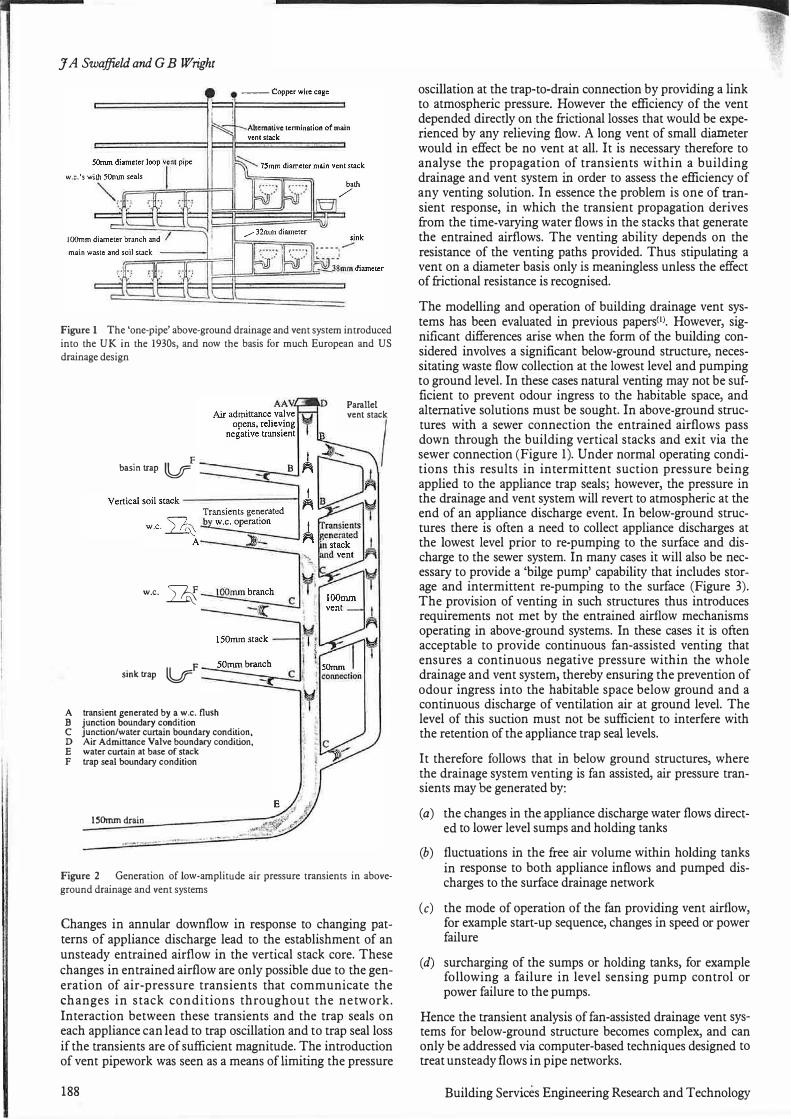
Design guides and, in the UK, British Standards Institution publications detail the degree of vencing to be provided. However, some of che design advice offered historically failed fully to recognise the causes of the transient pressures leading to trap seal depletion, or the operating regime of a 'vent'. It is therefore necessary to outline the mechanisms governing drainage system air pressure transient propagation. The random discharges of sanitary appliances create a time dependent annular flow in the drainage system vertical stacks that connect floors vertically to the sewer connection (Figure 2).
© 1998 The Chartered Institution of Building Services Engineers 187
J A Swaffield and GB Wright
Figure I The 'one-pipe' above-ground drainage and vent system introduced into the UK in the 1930s, and now the basis for much European and US drainage design
F basin trap ti/
w.c. �
F sinktrap V
A transient generated by a w .c. flush B junction boundary condition C junction/water curtain boundary condition, D Air Admittance Valve boundary condition, E water curtain at base of stack F trap seal boundary condition
150mmdrain
Parallel "'"'�l
Figure 2 Generation of low-amplitude air pressure transients in above-
ground drainage and vent systems
Changes in annular downflow in response to changing patterns of appliance discharge lead to the establishment of an unsteady entrained airflow in the vertical stack core. These changes in entrained airflow are only possible due to the generation of air-pressure transients that communicate the changes in stack conditions throughout the network. Interaction between these transients and the trap seals on each appliance can lead to trap oscillation and to trap seal loss if the transients are of sufficient magnitude. The introduction of vent pipework was seen as a means of limiting the pressure
188
oscillation at the trap-to-drain connection by providing a link to atmospheric pressure. However the efficiency of the vent depended directly on the frictional losses that would be experienced by any relieving flow. A long vent of small diameter would in effect be no vent at all. It is necessary therefore to analyse the propagation of transients within a building drainage and vent system in order to assess the efficiency of any venting solution. In essence the problem is one of transient response, in which the transient propagation derives from the time-varying water flows in the stacks that generate the entrained airflows. The venting ability depends on the resistance of the venting paths provided. Thus stipulating a vent on a diameter basis only is meaningless unless the effect of frictional resistance is recognised.
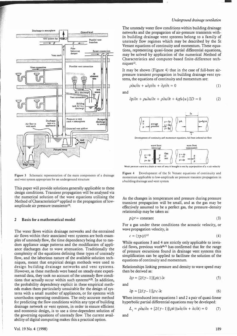
The modelling and operation of building drainage vent systems has been evaluated in previous papers<1J. However, significant differences arise when the form of the building considered involves a significant below-ground structure, necessitating waste flow collection at the lowest level and pumping to ground level. In these cases natural venting may not be sufficient to prevent odour ingress to the habitable space, and alternative solutions must be sought. In above-ground structures with a sewer connection the entrained airflows pass down through the building vertical stacks and exit via the sewer connection (Figure 1). Under normal operating conditions this results in intermittent suction pressure being applied to the appliance trap seals; however, the pressure in the drainage and vent system will revert to atmospheric at the end of an appliance discharge event. In below-ground structures there is often a need to collect appliance discharges at the lowest level prior to re-pumping to the surface and discharge to the sewer system. In many cases it will also be necessary to provide a 'bilge pump' capability that includes storage and intermittent re-pumping to the surface (Figure 3). The provision of venting in such structures thus introduces requirements not met by the entrained airflow mechanisms operating in above-ground systems. In these cases it is often acceptable to provide continuous fan-assisted venting that ensures a continuous negative pressure within the whole drainage and vent system, thereby ensuring the prevention of odour ingress into the habitable space below ground and a continuous discharge of ventilation air at ground level. The level of this suction must not be sufficient to interfere with the retention of the appliance trap seal levels.
It therefore follows that in below ground structures, where the drainage system venting is fan assisted, air pressure transients may be generated by:
(a) the changes in the appliance discharge water flows directed to lower level sumps and holding tanks
(b) fluctuations in the free air volume within holding tanks in response to both appliance inflows and pumped discharges to the surface drainage network
(c) the mode of operation of the fan providing vent airflow, for example start-up sequence, changes in speed or power failure
(d) surcharging of the sumps or holding tanks, for example following a failure in level sensing pump control or power failure to the pumps.
Hence the transient analysis of fan-assisted drainage vent systems for below-ground structure becomes complex, and can only be addressed via computer-based techniques designed to treat unsteady flows in pipe networks.
Building Services Engineering Research and Technology
----D-isc_h_arg_e_•o _• tmo_sp_h_ere-;"" I""I------"==-=-------. � T Cin>Undlevel
vent system fan
�
Vent slack f Paiallel vent '---....,,...---- branches
Flow baJancing damper
Possible vent connection
Figure 3 Schematic representation of the main components of a drainage
and vent system appropriate for an underground structure
This paper will provide solutions generally applicable to these design conditions. Transiem propagation will be analysed via the numerical solution of the wave equarions utilising rhe Method of Characteristics<Z> applied ro the propagation of lowamplirude air pressure transienr:s<3>.
2 Basis for a mathematical model
The warer flows within drainage nerworks and the enrrained air flows within their associared vent systems are both examples of unsteady flow, the time dependency being due to random appliance usage panems and the modification of appliance discharges due to wave acrenuation. Traditionally the complexity of cbe equations defining these types of unsteady flow, and the laborious nature of che available solution techniques, meant that empirical design methods were used co design building drainage networks and vent systems. However, as these methods were based on steady-state experimental dara, they took no accounc of the unsready flow conditions that actually occur within such system 4.5). In addition, the probability dependency explicit in these empirical methods makes them particularly unsuitable for the design of systems with a small number of appliances, or for systems with unorthodox operating conditions. The only accurate method for predicting the flow conditions within any type of building drainage nerwork or venc system, in order to ensure efficient and economic design, is to use a rime-dependenc solution of the governing equations of unsteady flow. The current availability of digital computing makes this a practical option.
Vol.19No.4 (1998)
Underground drainage ventilation The unsteady water flow conditions within building drainage nerworks and the propagation of air-pressure transients within building drainage venc systems belong to a family of unsteady flow regimes which may be described by che St Venant equations of continuity and momentum. These equations, representing quasi-linear partial differential equations, may be solved by application of the numerical Method of Characteristics and computer-based finite-difference techniques<2l.
It may be shown (Figure 4) that in the case of full-bore airpressure transient propagation in building drainage vent systems, the equations of continuity and momentum are:
and
pOufdX + UdpfdX + dpfdt = 0 (1)
2Jp/2Jx + pu.2Ju/2Jx + pdu/dt + 4pfu I u I /W = 0 (2)
p u p
Development of conlinuity and momentum equations, fuU bore induced air flow
wave front wave front (movin) (Slllllonary)
p + dp Ou p +dp p .. c -du p du c 1<$1 c
p+ dp p p+dp p
Weak pressure wave in a drain or vent of area A broughr lo rest by superposition of a -c air velocity
Figure 4 Development of the St Venant equations of continuity and
momentum applicable to low-amplitude air pressure transient propagation in
a building drainage and vent system
As the changes in temperature and pressure during pressure transient propagation will be small, and as the gas may be effectively assumed to be a perfect gas, the pressure-density relationship may be taken as:
pf pr= constant (3)
For a gas under these conditions the acoustic velocity, or wave propagation velocity, is
c = (yplp)112 (4)
While equations 3 and 4 are strictly only applicable to inviscid flows, previous work<6•7) has confirmed chat for the range of pressure excursions found in drainage vent systems this simplification can be applied to facilitate the solution of the equations of continuity and momentum.
Relationships linking pressure and density to wave speed may then be derived as:
(Jp = [2/(y- l)](p/c) (Jc (5)
and
(Jp = [2/(y- l)]p c oc (6)
When introduced into equations 1 and 2 a pair of quasi-linear hyperbolic partial differential equations may be developed:
L1 = p0u/ax + [2/(y- l)](p!c)(uoc/2Jx + 2Jc/2Jt) = O (7)
and
189

J A Swaffield and GB Wright
L2 = [2/(y- l)]fXdc/dx + pudu/dx + p(Ju/dt (pie) + 4pfa lu l12D = 0 (8)
Applying the Method of Characteristics yields the following total differential equations in terms of flow velocity u and acoustic velocity c:
du/dt ± [2/(y- l)]dc/dt + (4fu lu l/2D) = 0
dx/dt = u ± c
(9)
(10)
where y is the adiabatic index of air, f is the Darcy-W eisbach friction factor, D is the pipe diameter and c is defined in terms of the adiabatic index y, the air pressure p and the air density p by equation 4.
Note that the absolute value of air velocity in equation 9 ensures that friction always opposes motion.
The finite-difference form of these expressions, representing the c+ and c- characteristics,
or
up= Kl-K2cP
when
( 12)
dx/dt = u + c (13)
and
or
up= K3 + K2cP when
dx/dt = u - c
(15)
(16)
are only valid when the dx/dt condition, given by equation 10 and termed the Courant criterion, is satisfied. As such these characteristic lines, known generally in the literature as c+ and C- characteristics, defined by equation 10 and drawn in a two-dimensional space-time grid, may be thought of as routes along which information about the flow conditions at a particular location and time may be communicated to another location one time step in the future. Figure S illustrates these characteristics, which in finite-difference form represent a pair of simultaneous equations linking u and c in the future to known values one time step earlier, and the requirement to provide a suitable boundary equation at entry and exit to any pipe length, where naturally, due to the sign of dx/dt, only one characteristic equation can exist. Note the sign convention that positive flow occurs in the positive, or increasing, x direction. This implies that C+ characteristics slope 'downstream' and that duct sections terminate with a C+ characteristic, and vice versa for a C- characteristic. In the below-ground system application it is.helpful to set x = 0 at ground level, increasing with depth below the surface. As the normal fan-induced ventilation airflow will be towards the surface this implies that flow will be 'negative' within the sign convention assumed. This scheme has considerable computational advantages as the system can be represented as having one 'entry' point at x = 0 at the surface and a multiplicity of 'exit' points at each below-ground appliance or pipe junction.
It should be noted that, as air pressure and density are linked, it is necessary to express equations 9 and 10 in terms of flow velocity and acoustic velocity. The local pressure pp may then be calculated as:
190
Pp= [(p/por)(Jlc2)iJ110-J? (17)
where the suffix 0 refers to undisturbed air properties.
3 System boundary equations
The Method of Characteristics solution to the transient analysis of venting systems requires that conditions at entry and exit from a pipe length, where only one characteristic per pipe can exist under full-bore air flow conditions, be represented by a boundary equation that may be solved with the available characteristic, and probably the equation of continuity of mass flow, to yield the required values of flow velocity, wave speed and pressure. Examples of the boundary conditions relevant to below ground structures will be presented below and may be subdivided into three categories:
(a) Passive boundary conditions that arise as a result of the design of the system, for example junctions of two or more ducts, constant-pressure zones, dead ends, open discharge to atmosphere, changes in duct cross section. (As the amplitude of the transients considered is low, changes in duct wall thickness or material will have no measurable effect on wave speed and may be ignored.)
(b) Active boundary conditions that represent equipment connected to the system and whose operation may generate transients, for example the main fan, flow control dampers introduced to ensure flow balancing in multiroute systems, or air admittance valves that allow an inflow of ventilation air but close to prevent the escape of foul air from the system.
(c) Boundary conditions that arise as a result of the operation of the system and are not represented by any physical component; for example, the closure of a vent to sump access by surcharging will generate serious transients. Boundary conditions of this type will be dealt with in a later paper<8>.
As illustrated by Figure S it is necessary to solve the appropriate characteristic equation with a suitable boundary equation at entry and exit from a pipe length. Common boundary conditions include trap seals, junctions of two or more pipes and open or restricted access to the open air, i.e. passive conditions. The appropriate boundary equations link air pressure
Wave propagation,
note time step based
on Courant Criterion
Low-amf litudc air transients:� /- i ± '. � Time,t+6t
6t = £ • _!.&__ "' 0.003s I U+<: 340+20
:;; + �� T � �
� & TI�t
6x= Im
1--.. x+ve du +-3.. de + 4/U ful = 0 For air transients....... dt y-1 dt 2D
Figure S Summary of the Method of Characteristics applied to low-amplitude air-pressure transient propagation. Note importance of the boundary
equations representing duct section entry and exit.
Building Services Engineering Research and Technology
to air flow or pressure, or flow to rime, and have been adequately described previous1y<n. The application of the transient analysis co below-ground scrucrures requires that several particular boundary equations be introduced.
Figure 3 illustrated a typical below-ground installation incorporating the following additional and particular boundary conditions that depend upon the design of the below-ground network:
Mechanical fans, including fan speed changes
Fan distribution manifold and flow balancing dampers
Pump sumps
Holding tanks and associated air admittance valves
Appliance discharge to a pump sump, a holding tank or a manhole.
Further boundary conditions dependant upon the mode of operation of rhe system will be dealt with in a later paper covering system monitoring and simulation<8).
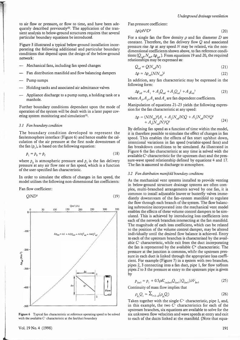
3.1 Fan boundary condition
The boundary condition developed to represent the fan/atmosphere interface (Figure 6) and hence enable the calculation of the air pressure at the first node downstream of the fan (p), is based on the following equation:
(18)
where p0 is atmospheric pressure and Pr is the fan delivery pressure at any air flow rate or fan speed, which is a function of the user-specified fan characteristic.
In order to simulate the effects of changes in fan speed, the model utilises the following non-dimensional fan coefficients:
Fan flow coefficient:
QJND3
0 50 100 Qref(l/s)
150 200 250
(19)
300 350 o+-��'--�--'��-'-��-'-��..__�__.���
1 l! 0. <l
- 100
-200
-300
400
6p,..r= Al+ A2Q.,,r+ AJQ2rc1+ A4Q)�'./.
'
'
2
Figure 6 Typical fan characteristic at reference operating speed to be solved with the available C- characteristic at the fan/duct boundary
Vol. 19 No. 4 (1998)
Underground drainage ventilation
Fan pressure coefficient: tlp/pN2D2 (20)
For a single fan the flow density p and fan diameter D are constant. Therefore, the fan delivery flow Q and associated pressure rise tlp at any speed may be related, via the nondimensional coefficients shown above, co fan reference conditions (Q, P Nr..r> tlpro). From equations 19 and 20, the required relationships may be expressed as:
Qr<f = Q(Nre/N) tlp = tlpr.{N/Nrer)2
(21)
(22)
In addition, any fan characteristic may be expressed in the following form:
"" =A + A Q +A Q 2 +A q 3 (23) '-'Y ref I 2 ref 3 re[ 4 ref where A1'A2,A3 andA4 are fan dependent coefficients. Manipulation of equations 21-23 yields the following expression for the fan characteristic at any speed:
tlp = (N/Nrel[ A1 + A2(N,JN)Q +A/NrJN)2Qz + A4(NjN)3Q3 (24)
By defining fan speed as a function of time within the model, it is therefore possible co simulate the effect of changes in fan speed. This enables the effects of fan start up/shut down, intentional variations in fan speed (variable-speed fans) and fan breakdown conditions to be simulated. As illustrated in Figure 6 the fan characteristic ac any time is solved with the available C- characteristic for the upstream duct and the pressure-wave speed relationship defined by equations· 4 and 17. The fan is assumed to discharge co atmosphere.
3.2 Fan distribution manifold boundary conditions
As the mechanical vent systems installed to provide venting in below-ground su·ucture drainage systems are often complex, multi-branched arrangements served by one fan, it is common to install adjustable louvre or bunerfly valves immediately downstream of che fan-system manifold to regulate the flow through each branch of the system. The flow balancing subroutine incorporated into the mechanical vent model enables the effects of these volume control dampers to be simulated. This is achieved by introducing loss coefficients into each of the network branches intersecting at the fan manifold. The magnitude of each loss coefficient, which can be related co the position of the volume control damper, may be altered individually until the desired flow balance is achieved. Entry co each of the upstream branches is characterised by the available C- characteristic, while exit from the duce incorporating the fan is represented by the available C+ characteristic. The pressure at the junction is common, while the upstream pressure in each duct is linked through the appropriate loss coefficient. For example (Figure 7) in a system with two branches, pipes 2, 3 connecting into a fan duce, pipe 1, for flow to/from pipes 2 to 3 the pressure ac entry to the upmeam pipe is given by
P2or3 == P1 + O.SpKlto2or3QZor31Qior31/A2mr3 Continuity of mass flow implies that
PP1Ql = L,=2-JPP,Q)
(25)
(26)
Taken together with the single C+ characteristic, pipe 1, and, in this example, the two C- characteristics for each of the upstream branches, six equations are available to solve for the six unknown flow velocities and wave speeds at entry and exit to each of the ducts linked at the manifold. (Note chat equa-
191

J A Swaffield and GB Wright
mechanical vent pipe terminates to atmosphere
FAN
p, I
Figure 7 Available characteristics at a junction incorporating volume control dampers
tions 4 and 17 are also required to link wave speed to air pressure in each case). Solution is normally via the bisection technique.
It will be appreciated from the development of this boundary condition that this approach would also apply to junctions of two or more ducts where there was either no assumed loss or a loss coefficient for each path dependent only on the design of the junction.
3.3 Pump sump boundary candition
As shown in Figure 8, a pump sump is a low-level, unsealed collection sump which receives appliance (not we) and pump discharges. To prevent build-up of odour in and around pump sumps, they are always connected to a mechanical vent system.
The boundary condition developed to represent a pump sump is based on a representation of the air volume change within the sump over a simulation time step, determined by the Courant Criterion.
mechanical vent pipe connected to fan�
w11ter _-_..;----innuw �
.-· -,, , ___ _ I I "; B '
variable wan.�.r CYC
-- water outflow
----_.,,..,__ water ! � innow
c : r(1 - - -.j '
- - - - represents possible air flow paths
C •characteristic available at points A, B and C
Figure 8 Flow conditions and available characteristics at a pump sump (Note that the sump may become surcharged so that the mechanical vent may become submerged.)
192
The air volume in the sump at any time t, may be expressed as
J!1 == V ,_"" + f1V + .1V + Q (28) ps ps wat U1 vem
where J!1 and V 1-tJJ are the sump air volume across a time ps , ps • • step, .1V 1s the net mflow of water to the sump across a time step, .1V"' is the nett air volume infiltrating into the sump from the
msurrounding space, Q is given by the c+ charac-vent
teristic at the vent-to-sump interface. As the initial free air volume in the sump is known and as the inflows of water to the sump are known from appliance discharge and pump operation records, it is possible to determine the vent airflow and the infiltration to the tank from the surrounding space. The pressure-wave speed equations 4 and 17 are again utilised.
The infiltration air flow from the surrounding space depends on both the pressure differential between the sump and an effective loss coefficient to represent the degree of sealing provided by the sump covers. As these are normally a loose fit, this loss coefficient will be low, and the sump pressure will be only slightly below atmospheric. The design of such sumps reinforces the decision to provide a mechanical ventilation system to ensure the prevention of odour ingress to the surrounding space from the sump. Such sumps do not accept we discharges.
3.4 Holding tank boundary candition
As shown in Figure 9, a holding tank is a low level, sealed collection sump which receives appliance discharges (mainly wcs). In order to prevent the accumulation of foul odour and the depletion of appliance trap seals during pump operation, a
vent pipe not connected to fan
mechanical vent pipe connected to fan
/ pipe I
- - - - represents possible air flow paths
c+characteristic available at points A and C
c· characteristic available at point B
Figure 9 Flow conditions and available characteristics at a holding tank (Note that the tank requires separate venting as it accepts we discharge and that the dedicated vent is normally either open to atmosphere or terminated by an air admittance valve, dependent upon depth below ground.)
Building Services Engineering Research and Technology
-

holding tank is always connected to a mechanical vent system. An additional vent pipe (e.g. pipe 2 in Figure 9), normally terminating at an air admittance valve, is also installed to prevent appliance trap seal depletion due to the action of the fan.
The sump-style boundary equation (27) may be modified by removal of the infiltration term as follows:
v I = v I-DJ + �v + ""'r. ps ps wal �\·ent (28)
where IQvent includes the dedicated vent airflow and the airflow to the main vent network.
The air flow entering and leaving the collection tank is determined by reference to the available c+ and c- characteristics. The pressure within the tank may be determined from the gas laws if it is assumed that the tank free air volume and pressure at time zero are known; they are normally assumed to be atmospheric prior to fan start-up. Equations 4 and 17 are again utilised to link wave speed in the characteristic equations to air pressure.
It will be appreciated that the volume of free air within the holding tank will affect the damping of any transient arriving from the remainder of the system. Foul water and waste are removed from holding tanks by remote pumps, and the consequent changes in free air volume above the contained water surface will generate transients that will propagate into the general vent network and also into the dedicated holding tank vent, resulting in operation of its terminal air admittance valve.
3.5 Air admittance valve boundary condition
Air admittance valves are used to terminate the dedicated vent from a holding tank (Figure 9). The boundary condition involves solution of the relevant C+ characteristic with the separation loss across the valve. The valve may be represented by three pressure zones:
(a) with the valve closed, i.e. the pressure in the vent is positive or not sufficiently negative to open the valve. In this case the boundary condition is zero flow as shown:
u = 0.0 ex (29)
(b) with the valve partially open, i.e. the suction pressure in the vent lifts the valve diaphragm but not fully. The local separation loss may then be included in a definition of the pressure in the vent beneath the valve as
Patm -Pex = K0.5pu2ex (30)
The inflow of ventilation air into the vent pipe thus depends on both the differential pressure and the loss coefficient K applicable at that differential pressure.
(c) with the valve fully open, i.e. the suction pressure in the vent is sufficient to lift the diaphragm fully, the inflow then depending on the differential pressure alone:
where Kmin is the fully open valve loss coefficient.
(31)
In each case the boundary equation is solved with the C+ characteristic via equations 4 and 17. The form of the loss coefficient-differential pressure relationship for air admittance valves takes the form of a loss coefficient that drops rapidly as the differential suction pressure across the diaphragm increases, approaching a constant value as the
Vol. 19 No. 4 (1998)
Underground drainage ventilation
diaphragm lifts fully<1J>. A 'good' air admittance valve performance is characterised by a rapid fall in loss coefficient, with the fully open position reached at a differential suction pressure in the region oflOO to 400 N m-2.
3.6 Appliance discharge boundary condition
The boundary condition developed to represent an appliance discharge to a pump sump, holding tank or a manhole is based on the following equation:
(32)
where p is the air pre sure at termination of the pipe conveying the appliance discharge,p0 is atmospheric pressure andpw is the change in air pressure induced by the appliance discharge, which has been shown co be a function of the water flow rate and the diameter of the discharge drainC1> - normally 100 mm in the class of drainage system considered in this paper.
4 Conclusions
The operation of fan-assisted below-ground drainage vent systems has been described and shown to be capable of transient analysis utilising the Method of Characteristics to handle the solution of the St Venant equations of continuity and momentum. Classes of boundary condition have been identified and the appropriate boundary equations solved with the available characteristics to allow a system simulation to be undertaken.
The boundary conditions particular to below-ground structure drainage applications have been considered in detail. It is apparent that while the transients generated by operation of such systems are related co chose expecred from above-ground drainage network the incroduccion of fan-assisred venting, pumped sump and possibilities of surcharge and power failure introduce particular conditions requiring analysis.
As a result of the model development presented, a simulation of the operation and transient response of installed systems was required. That study, involving the monitoring of the air pressure transients and entrained air flows within a typical below-ground structure drainage system, has been undertaken and will be presented separately. The outcome of the monitoring and simulation confirmed the applicability of the techniques presented in this paper.
Acknowledgements
The work reported was supported by UK Engineering and Physical Science Research Council Award GR/F24863 (1989/92) and later by London Underground Ltd research contract 502527 (1993/96). This support is gratefully acknowledged.
193

J A Swaffield and GB Wright
References
Swaffield J A and Campbell D P The simulation of air pressure transient propagation in building drainage and vent systems Building and Environment 30(1) 115-127 (1995)
2 Lister M The numerical solution of hyperbolic partial differential equations
by the method of characteristics in Numerical Methods for Digital Computers ed. Ralston A and WilfH S (New York: Wiley) (1960)
3 Swaffield J A and Boldy A P Pressure surge in pipe and duct systems p358 (Aldershot: Avebury Technical/Gower Press) (1994)
4 Hunter RB Methods of estimating leads in plumbing systems BMS 65 p21 (Washington DC: US National Bureau of Standards) (1940)
194
5 Wise A E Water, sanitary and waste services for buildings 4th edn p216
(London: Longman) (1994)
6 Henson D A and Fox J A Transient flows in tunnel complexes of the type proposed for the Channel Tunnel Proc. Inst. Mech. Eng. 188(1Sn4) 153--167 (1972)
7 Woodhead C A, Fox J A and Vardy A E Analysis of water curtains in
transient gas flows in ducts Proc. 2nd. Int. Conf Pressure Surge ppKl-19 (1976)
8 Swaffield J A and Wright GB Drainage ventilation systems for under
ground systems II: Simulation of transient response Proc. CIBSE A: Building Sero. Eng. Res. Technol. 19(4) 195-202 (1998)
Building Services Engineering Research and Technology