Embed Size (px)
Citation preview
21901 ENFIELD PAVILION 2020.0316
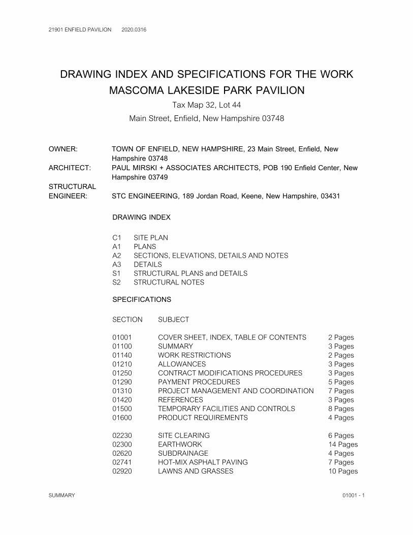
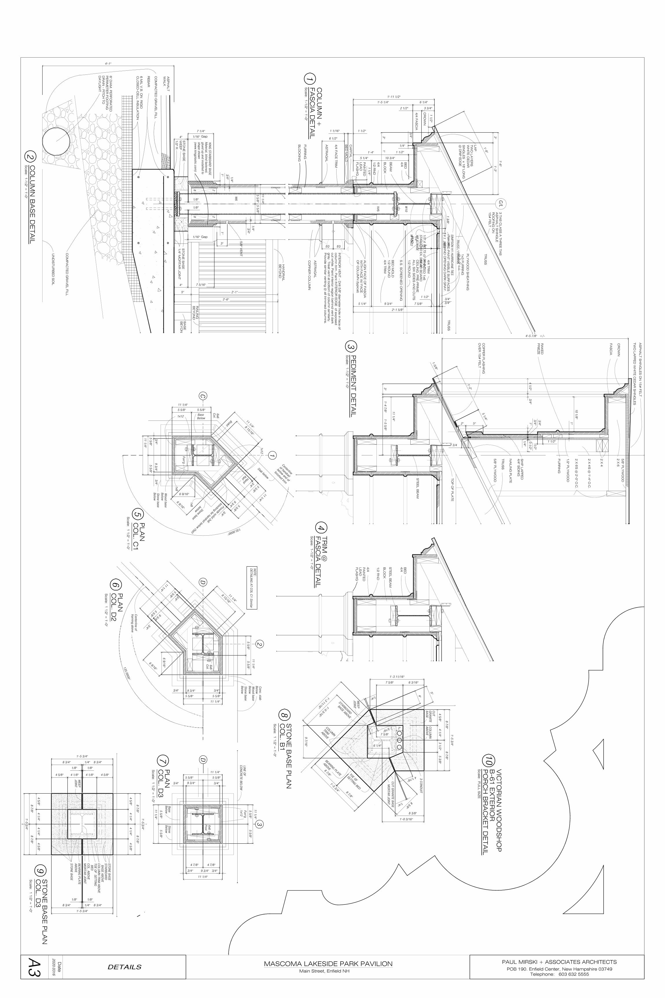
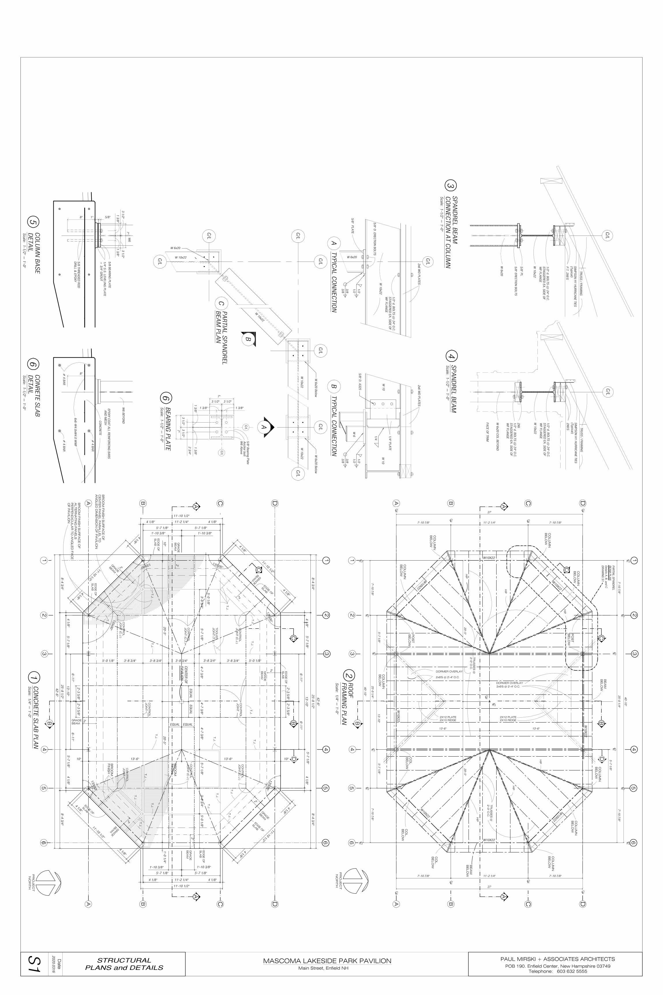
DRAWING INDEX AND SPECIFICATIONS FOR THE WORKMASCOMA LAKESIDE PARK PAVILION
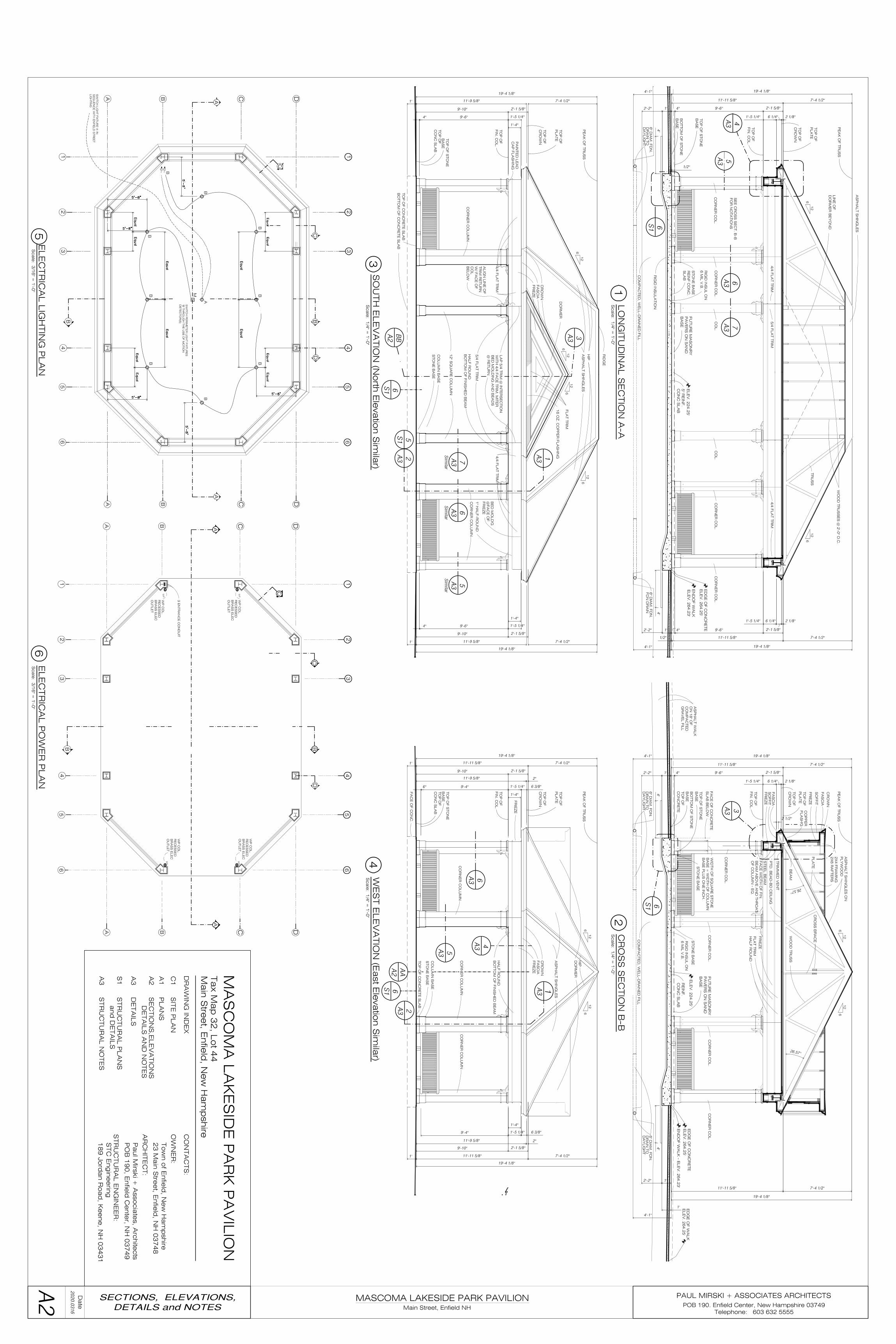
Tax Map 32, Lot 44Main Street, Enfield, New Hampshire 03748
OWNER: TOWN OF ENFIELD, NEW HAMPSHIRE, 23 Main Street, Enfield, New Hampshire 03748
ARCHITECT: PAUL MIRSKI + ASSOCIATES ARCHITECTS, POB 190 Enfield Center, New Hampshire 03749
STRUCTURAL ENGINEER: STC ENGINEERING, 189 Jordan Road, Keene, New Hampshire, 03431
DRAWING INDEX
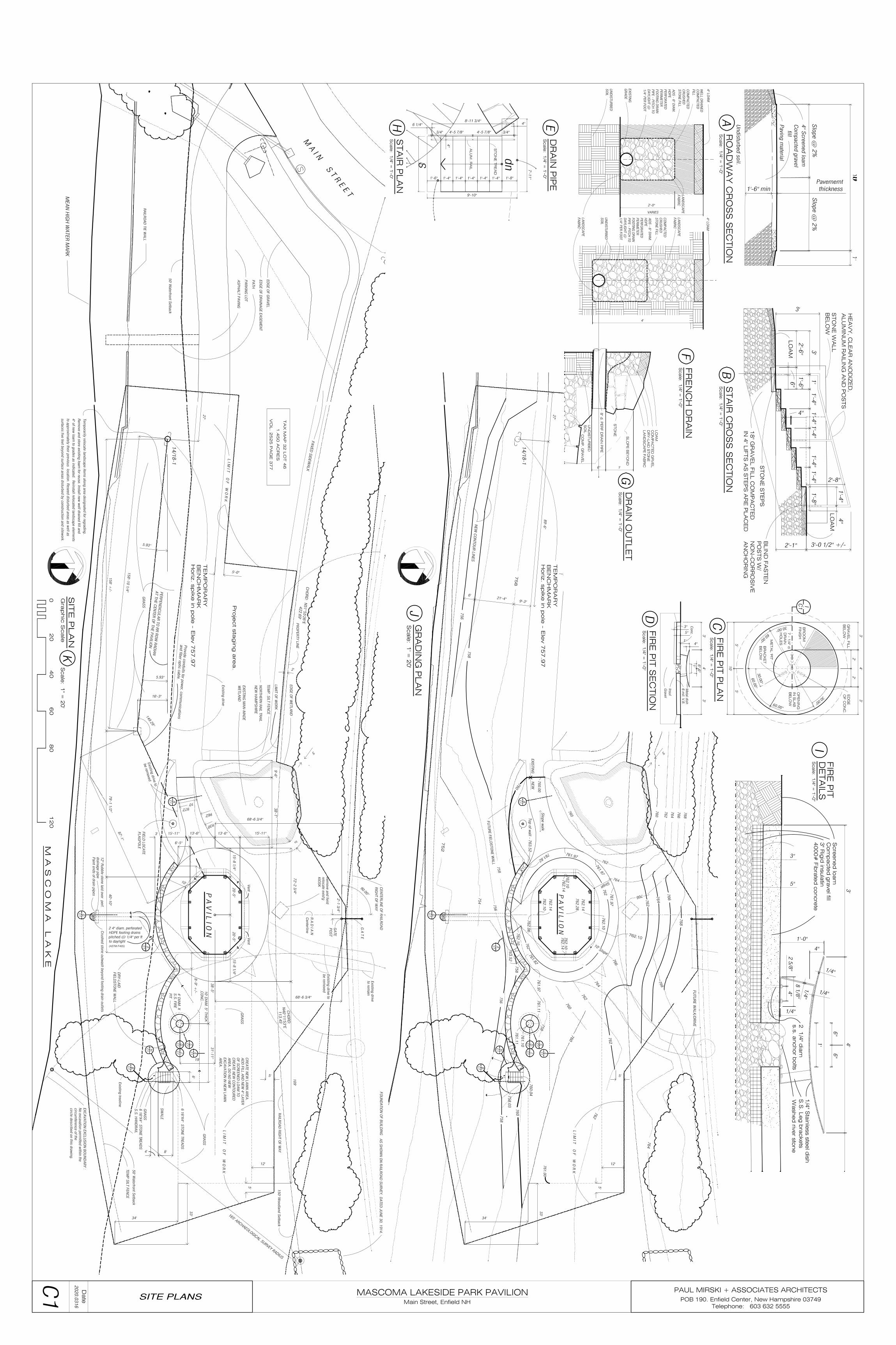
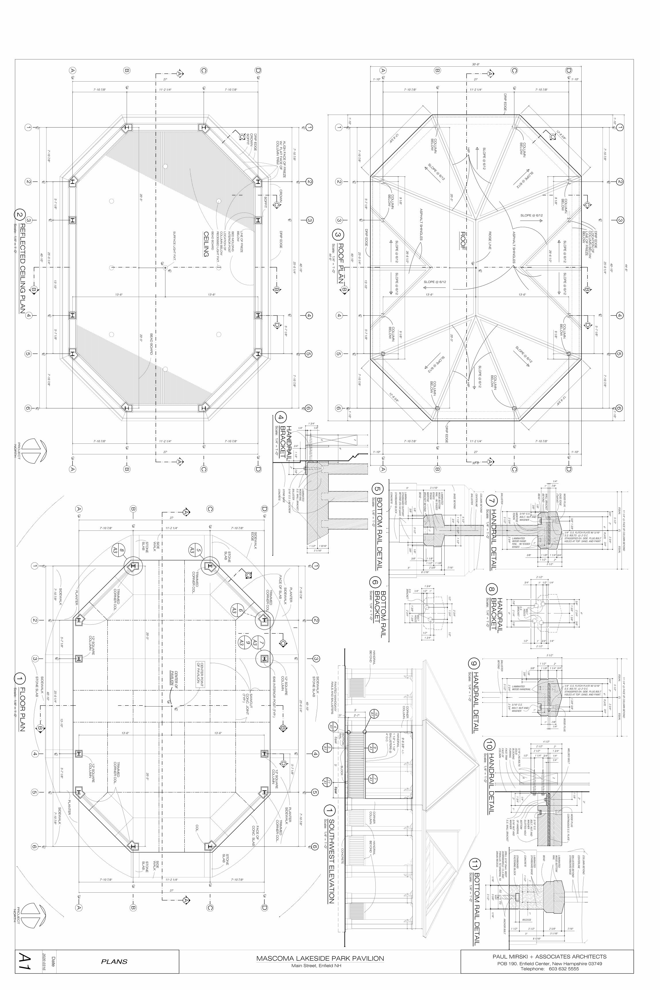
C1 SITE PLANA1 PLANSA2 SECTIONS, ELEVATIONS, DETAILS AND NOTESA3 DETAILSS1 STRUCTURAL PLANS and DETAILSS2 STRUCTURAL NOTES
SPECIFICATIONS
SECTION SUBJECT
01001 COVER SHEET, INDEX, TABLE OF CONTENTS 2 Pages01100 SUMMARY 3 Pages01140 WORK RESTRICTIONS 2 Pages01210 ALLOWANCES 3 Pages01250 CONTRACT MODIFICATIONS PROCEDURES 3 Pages01290 PAYMENT PROCEDURES 5 Pages01310 PROJECT MANAGEMENT AND COORDINATION 7 Pages01420 REFERENCES 3 Pages01500 TEMPORARY FACILITIES AND CONTROLS 8 Pages01600 PRODUCT REQUIREMENTS 4 Pages
02230 SITE CLEARING 6 Pages02300 EARTHWORK 14 Pages02620 SUBDRAINAGE 4 Pages02741 HOT-MIX ASPHALT PAVING 7 Pages02920 LAWNS AND GRASSES 10 Pages
SUMMARY 01001 - 1
21901 ENFIELD PAVILION 2020.0316
03300 CAST IN PLACE CONCRETE 8 Pages05120 STRUCTURAL STEEL 7 Pages06100 ROUGH CARPENTRY 3 Pages06200 FINISH CARPENTRY 7 Pages07311 ASPHALT SHINGLES 5 Pages07620 SHEET METAL FLASHING 5 Pages09638 STONE COLUMN BASES 7 Pages09911 PAINTING (CONSUMER LINE PRODUCTS) 10 pages10350 FLAGPOLE 4 Pages12496 WINDOW (OPENING) TREATMENT HARDWARE 3 Pages
TOTAL 136 Pages
MISCELLANEOUS:
NOTE: Structural Specifications may be found on DRAWING S2, DatedMarch 16, 2020
SUMMARY 01001 - 2

21901 ENFIELD PAVILION 2020.0316
SECTION 01100 - SUMMARY
PART 1 - GENERAL
1.1 RELATED DOCUMENTS
A. Drawings and general provisions of the Contract, including General and SupplementaryConditions and other Division 1 Specification Sections, apply to this Section.
1.2 WORK COVERED BY CONTRACT DOCUMENTS
A. Project Identification1. Project Location: MAIN STREET, ENFIELD TAX MAP 32, LOT 44 (Lakeside)2. Owner: TON OF ENFIELD, NH, 23 MAIN STREET, POB 373, ENFIELD, NH
03748
B. Architect Identification: The Contract Documents, dated MARCH 16, 2020 were preparedfor Project by PAUL MIRSKI + ASSOCIATES ARCHITECTS, POB 190, ENFIELDCENTER, NH 03749.
C. The Work consists of THE CONSTRUCTION OF A STEEL FRAMED/WOOD-TRUSSED, OPEN AIR PAVILION OF APPROXIMATELY 1200 S.F., SET ON AFLOATING “ALASKAN SLAB.
1.3 CONTRACT[S]
A. Project will be constructed under AIA141-2004, AGREEMENT BETWEEN OWNERAND DESIGN-BUILDER, ON THE BASIS OF THE COST OF THE WORK PLUSDESIGN-BUILDERS FEE WITH A GUARANTEED MAXIMUM PRICE.
1.4 WORK SEQUENCE
A. The Work shall be conducted in ONE, SINGLE, PHASE.
B. USE OF PREMISES
C. GENERAL: THE CONTRACTOR, AND HIS SUPERVISED SUB-CONTRACTORSSHALL HAVE FULL USE OF THE PREMISES WITHIN THE LIMITS OF THE WORK
SUMMARY 01100 - 1
21901 ENFIELD PAVILION 2020.0316
SHOWN, FOR CONSTRUCTION OPERATIONS, INCLUDING USE OF PROJECTSITE DURING CONSTRUCTION PERIOD. CONTRACTORS USE OF PREMISES ISLIMITED ONLY BY OWNERS RIGHT TO PERFORM WORK OR TO RETAINOTHER CONTRACTORS ON PORTIONS OF THE PROJECT. Contractor's use ofpremises is limited only by Owner's right to perform work or to retain other contractors onportions of Project.
1.5 WORK UNDER OTHER CONTRACTS
A. Separate Contract: Owner MAY AWARD A SEPARATE CONTRACT HAVING TO DOWITH ARCHAEOLOGICAL SURVEY WORK AT THE PROJECT SITE. THESURVEY WORK MAY BE SCHEDULED DURING THE CONSTRUCTION PHASEBUT THE SUB-CONTRACTOR WILL BE REQUIRED TO CONDUCT THEIR WORKIN A MANNER THAT WILL NOT CREATE ANY CAUSE FOR DELAY IN THECOMPLETION OF THE WORK..
B. Cooperate fully with separate contractors so work on those contracts may be carried outsmoothly, without interfering with or delaying work under this Contract.
1.6 SPECIFICATION FORMATS AND CONVENTIONS
A. Specification Format: The Specifications are organized into Divisions and Sections usingthe 16-division format and CSI/CSC's "MasterFormat" numbering system.
1. Section Identification: The Specifications use section numbers and titles to helpcross-referencing in the Contract Documents. Sections in the Project Manual are innumeric sequence; however, the sequence is incomplete. Consult the table ofcontents at the beginning of the Project Manual to determine numbers and names ofsections in the Contract Documents.
B. Specification Content: The Specifications use certain conventions for the style of languageand the intended meaning of certain terms, words, and phrases when used in particularsituations. These conventions are as follows:
1. Abbreviated Language: Language used in the Specifications and other ContractDocuments is abbreviated. Words and meanings shall be interpreted as appropriate. Words implied, but not stated, shall be inferred as the sense requires. Singular wordsshall be interpreted as plural, and plural words shall be interpreted as singular whereapplicable as the context of the Contract Documents indicates.
2. Imperative mood and streamlined language are generally used in the Specifications. Requirements expressed in the imperative mood are to be performed by Contractor. Occasionally, the indicative or subjunctive mood may be used in the Section Text for
SUMMARY 01100 - 2

21901 ENFIELD PAVILION 2020.0316
clarity to describe responsibilities that must be fulfilled indirectly by Contractor orby others when so noted.
a. The words "shall," "shall be," or "shall comply with," depending on thecontext, are implied where a colon (:) is used within a sentence or phrase.
END OF SECTION 01100
SUMMARY 01100 - 3
21901 ENFIELD PAVILION 2020.0316
SECTION 01140 - WORK RESTRICTIONS
PART 1 - GENERAL
1.1 RELATED DOCUMENTS
A. Drawings and general provisions of the Contract, including General and SupplementaryConditions and other Division 1 Specification Sections, apply to this Section.
1.2 USE OF PREMISES
A. Use of Site: Limit use of premises to work in areas indicated. Do not disturb portions ofsite beyond areas in which the Work is indicated.
1. Limits: Confine constructions operations to BE CONTAINED WITHIN THE‘LIMIT OF WORK’ SHOWN ON THE DRAWINGS.
2. Owner Occupancy: Allow for Owner occupancy of site.3. Driveways and Entrances: Keep driveways and entrances serving premises
BEYOND THE LIMIT OF WORK clear and available to Owner, Owner'semployees, and emergency vehicles at all times. Do not use these areas for parkingor storage of materials.
a. Schedule deliveries to minimize use of driveways and entrances.b. Schedule deliveries to minimize space and time requirements for storage of
materials and equipment on-site.
1.3 OCCUPANCY REQUIREMENTS
A. Full Owner Occupancy: Owner will occupy THE SITE BEYOPND THE LIMITS OFWORK FOR PUBLIC PARK USE. Cooperate with Owner during construction operationsto minimize conflicts and facilitate Owner usage. Perform the Work so as not to interferewith Owner's operations.1. Architect will prepare a Certificate of Substantial Completion for each specific
portion of the Work to be occupied before Owner occupancy.2. Obtain a Certificate of Occupancy from authorities having jurisdiction before Owner
occupancy.3. Before partial Owner occupancy, electrical systems shall be fully operational, and
required tests and inspections shall be successfully completed. On occupancy,
WORK RESTRICTIONS 01140 - 1
21901 ENFIELD PAVILION 2020.0316
Owner will provide, operate, and maintain electrical systems serving occupiedportions of SITE.
4. On occupancy, Owner will assume responsibility for maintenance and custodialservice SITE.
5. END OF SECTION 01140
WORK RESTRICTIONS 01140 - 2
21901 ENFIELD PAVILION 2020.0316
SECTION 01210 - ALLOWANCES
PART 1 - GENERAL
1.1 RELATED DOCUMENTS
A. Drawings and general provisions of the Contract, including General and SupplementaryConditions and other Division 1 Specification Sections, apply to this Section.
1.2 SUMMARY
A. This Section includes administrative and procedural requirements governing allowances.
1. Certain materials and equipment are specified in the Contract Documents byallowances. In some cases, these allowances include installation. Allowances havebeen established in lieu of additional requirements and to defer selection of actualmaterials and equipment to a later date when additional information is available forevaluation. If necessary, additional requirements will be issued by Change Order.
B. Types of allowances MAY include the following:
1. Lump-sum allowances.2. Unit-cost allowances.3. Contingency allowances.4. Testing and inspecting allowances.5. Quantity allowances.
C. Related Sections include the following:
1. Division 1 Section "Contract Modification Procedures" for procedures for submittingand handling Change Orders.
2. Division 1 Section "Unit Prices" for procedures for using unit prices.3. Division 1 Section "Quality Requirements" for procedures governing the use of
allowances for testing and inspecting.
1.3 SELECTION AND PURCHASE
ALLOWANCES 01210 - 1
21901 ENFIELD PAVILION 2020.0316
A. At the earliest practical date after award of the Contract, advise Architect of the date whenfinal selection and purchase of each product or system described by an allowance must becompleted to avoid delaying the Work.
B. At Architect's request, obtain proposals for each allowance for use in making finalselections. Include recommendations that are relevant to performing the Work.
C. Purchase products and systems selected by Architect from the designated supplier.
1.4 SUBMITTALS
A. Submit proposals for purchase of products or systems included in allowances, in the formspecified for Change Orders.
B. Submit invoices or delivery slips to show actual quantities of materials delivered to the sitefor use in fulfillment of each allowance.
1.5 CONTINGENCY ALLOWANCES
A. Use the contingency allowance only as directed by Architect for Owner's purposes and onlyby Change Orders that indicate amounts to be charged to the allowance.
B. Contractor's OVERHEAD AND ALL related costs for products and equipment ordered byOwner under the contingency allowance are included in the allowance and are not part ofthe Contract Sum. These costs include delivery, installation, taxes, insurance, equipmentrental, and similar costs.
C. Change Orders authorizing use of funds from the contingency allowance will includeContractor's related costs and reasonable overhead and profit margins.
D. At Project closeout, credit unused amounts remaining in the contingency allowance toOwner by Change Order.
1.6 TESTING AND INSPECTING ALLOWANCES
A. Testing and inspecting allowances include the cost of engaging testing agencies, actual testsand inspections, and reporting results.
B. The allowance does not include incidental labor required to assist the testing agency orcosts for retesting if previous tests and inspections result in failure.
ALLOWANCES 01210 - 2
21901 ENFIELD PAVILION 2020.0316
C. Costs of services not required by the Contract Documents are not included in the allowance.
D. At Project closeout, credit unused amounts remaining in the testing and inspectingallowance to Owner by Change Order.
1.7 UNUSED MATERIALS
A. Return unused materials purchased under an allowance to manufacturer or supplier forcredit to Owner, after installation has been completed and accepted.
1. If requested by Architect, prepare unused material for storage by Owner when it isnot economically practical to return the material for credit. If directed by Architect,deliver unused material to Owner's storage space. Otherwise, disposal of unusedmaterial is Contractor's responsibility.
EXECUTION
1.8 EXAMINATION
A. Examine products covered by an allowance promptly on delivery for damage or defects. Return damaged or defective products to manufacturer for replacement.
1.9 PREPARATION
A. Coordinate materials and their installation for each allowance with related materials andinstallations to ensure that each allowance item is completely integrated and interfaced withrelated work.
1.10 SCHEDULE OF ALLOWANCES
A. ELECTRICAL LIGHTING AND POWER ALLOWANCE: Include ALL CONDUITS,EXCAVATION, AND ALL COMPONENTS REQUIRED TO PROVIDE FOR A FULLYOPERATIONAL ELECTRICAL AND POWER SYSTEM FOR THE WORK.
END OF SECTION 01210
ALLOWANCES 01210 - 3
21901 ENFIELD PAVILION 220.0316
SECTION 01250 - CONTRACT MODIFICATION PROCEDURES
PART 1 - GENERAL
1.1 RELATED DOCUMENTS
A. Drawings and general provisions of the Contract, including General and SupplementaryConditions and other Division 1 Specification Sections, apply to this Section.
1.2 SUMMARY
A. This Section specifies administrative and procedural requirements for handling andprocessing Contract modifications.
B. Related Sections include the following:
1. Division 1 Section "Allowances" for procedural requirements for handling andprocessing allowances.
2. Division 1 Section "Unit Prices" for administrative requirements for using unitprices.
3. Division 1 Section "Product Requirements" for administrative procedures forhandling requests for substitutions made after Contract award.
1.3 MINOR CHANGES IN THE WORK
A. Architect will issue supplemental instructions authorizing Minor Changes in the Work, notinvolving adjustment to the Contract Sum or the Contract Time, on AIA Document G710,"Architect's Supplemental Instructions."
1.4 PROPOSAL REQUESTSARCHITECT will issue a detailed description of proposed changes in the Work that may requireadjustment to the Contract Sum or the Contract Time. If necessary, the description will includesupplemental or revised Drawings and Specifications.
1. Proposal Requests issued by ARCHITECT are for information only. Do not considerthem instructions either to stop work in progress or to execute the proposed change.
2. Within 14 (FOURTEEN) DAYS after receipt of Proposal Request, submit aquotation estimating cost adjustments to the Contract Sum and the Contract Timenecessary to execute the change.
CONTRACT MODIFICATION PROCEDURES 01250 - 1

21901 ENFIELD PAVILION 220.0316
a. Include a list of quantities of products required or eliminated and unit costs,with total amount of purchases and credits to be made. If requested, furnishsurvey data to substantiate quantities.
b. Indicate applicable taxes, delivery charges, equipment rental, and amounts oftrade discounts.
c. Include an updated Contractor's Construction Schedule that indicates the effectof the change, including, but not limited to, changes in activity duration, startand finish times, and activity relationship. Use available total float beforerequesting an extension of the Contract Time.
B. Contractor-Initiated Proposals: If latent or unforeseen conditions require modifications tothe Contract, Contractor may propose changes by submitting a request for a change TOARCHITECT.1. Include a statement outlining reasons for the change and the effect of the change on
the Work. Provide a complete description of the proposed change. Indicate theeffect of the proposed change on the Contract Sum and the Contract Time.
2. Include a list of quantities of products required or eliminated and unit costs, withtotal amount of purchases and credits to be made. If requested, furnish survey datato substantiate quantities.
3. Indicate applicable taxes, delivery charges, equipment rental, and amounts of tradediscounts.
4. Include an updated Contractor's Construction Schedule that indicates the effect of thechange, including, but not limited to, changes in activity duration, start and finishtimes, and activity relationship. Use available total float before requesting anextension of the Contract Time.
5. Comply with requirements in Division 1 Section "Product Requirements" if theproposed change requires substitution of one product or system for product or systemspecified.
C. Proposal Request Form: Use AIA Document G709 for Proposal Requests.
D. Proposal Request Form: For Change Order proposals, use forms provided by Owner. Sample copies are included at end of this Section.
1.5 ALLOWANCES
A. Allowance Adjustment: To adjust allowance amounts, base each Change Order proposalon the difference between purchase amount and the allowance, multiplied by finalmeasurement of work-in-place. If applicable, include reasonable allowances for cuttinglosses, tolerances, mixing wastes, normal product imperfections, and similar margins.
1. Include installation costs in purchase amount only where indicated as part of theallowance.
CONTRACT MODIFICATION PROCEDURES 01250 - 2

21901 ENFIELD PAVILION 220.0316
2. If requested, prepare explanation and documentation to substantiate distribution ofoverhead costs and other margins claimed.
3. Submit substantiation of a change in scope of work, if any, claimed in Change Ordersrelated to unit-cost allowances.
4. Owner reserves the right to establish the quantity of work-in-place by independentquantity survey, measure, or count.
B. Submit claims for increased costs because of a change in scope or nature of the allowancedescribed in the Contract Documents, whether for the Purchase Order amount orContractor's handling, labor, installation, overhead, and profit. Submit claims within 14(FOURTEEN) days of receipt of the Change Order or Construction Change Directiveauthorizing work to proceed. Owner will reject claims submitted later than 14(FOURTEEN) days after such authorization.
1. Do not include Contractor's or subcontractor's indirect expense in the Change Ordercost amount unless it is clearly shown that the nature or extent of work has changedfrom what could have been foreseen from information in the Contract Documents.
2. No change to Contractor's indirect expense is permitted for selection of higher- orlower-priced materials or systems of the same scope and nature as originallyindicated.
1.6 CHANGE ORDER PROCEDURES
A. On Owner's approval of a Proposal Request, ARCHITECT will issue a Change Order forsignatures of Owner and Contractor on AIA Document G701.
1.7 CONSTRUCTION CHANGE DIRECTIVE
A. WORK Change Directive: ARCHITECT may issue a WORK Change Directive on AIADocument G714. WORK Change Directive instructs Contractor to proceed with a changein the Work, for subsequent inclusion in a Change Order.
1. Work Change Directive contains a complete description of change in the Work. Italso designates method to be followed to determine change in the Contract Sum orthe Contract Time.
B. Documentation: Maintain detailed records on a time and material basis of work requiredby the WORK Change Directive.
1. After completion of change, submit an itemized account and supporting datanecessary to substantiate cost and time adjustments to the Contract.
END OF SECTION 01250
CONTRACT MODIFICATION PROCEDURES 01250 - 3

21901 ENFIELD PAVILION 220.0316
CONTRACT MODIFICATION PROCEDURES 01250 - 4
21901 ENFIELD PAVILION 2020.0316
SECTION 01290 - PAYMENT PROCEDURES
PART 1 - GENERAL
1.1 RELATED DOCUMENTS
A. Drawings and general provisions of the Contract, including General and SupplementaryConditions and other Division 1 Specification Sections, apply to this Section.
1.2 SUMMARY
A. This Section specifies administrative and procedural requirements necessary to prepare andprocess Applications for Payment.
B. Related Sections include the following:
1. Division 1 Section "Allowances" for procedural requirements governing handlingand processing of allowances.
2. Division 1 Section "Unit Prices" for administrative requirements governing use ofunit prices.
3. Division 1 Section "Contract Modification Procedures" for administrative proceduresfor handling changes to the Contract.
4. Division 1 Section "Construction Progress Documentation" for administrativerequirements governing preparation and submittal of Contractor's ConstructionSchedule and Submittals Schedule.
1.3 DEFINITIONS
A. Schedule of Values: A statement furnished by Contractor allocating portions of theContract Sum to various portions of the Work and used as the basis for reviewingContractor's Applications for Payment.
1.4 SCHEDULE OF VALUES
A. Coordination: Coordinate preparation of the Schedule of Values with preparation ofContractor's Construction Schedule.
1. Correlate line items in the Schedule of Values with other required administrativeforms and schedules, including the following:
PAYMENT PROCEDURES 01290 - 1
21901 ENFIELD PAVILION 2020.0316
a. Application for Payment forms with Continuation Sheets.b. Submittals Schedule.
2. Submit the Schedule of Values to Architect at earliest possible date but no laterthanSEVEN days before the date scheduled for submittal of initial Applications forPayment.
3. Subschedules: Where the Work is separated into phases requiring separately phasedpayments, provide subschedules showing values correlated with each phase ofpayment.
B. Format and Content: Use the Project Manual table of contents as a guide to establish lineitems for the Schedule of Values. Provide at least one line item for each SpecificationSection.
1. Identification: Include the following Project identification on the Schedule ofValues:
a. Project name and location.b. Name of Architect.c. Architect's project number.d. Contractor's name and address.e. Date of submittal.
2. Arrange the Schedule of Values in tabular form with separate columns to indicate thefollowing for each item listed:
a. Related Specification Section or Division.b. Description of the Work.c. Name of subcontractor.d. Name of manufacturer or fabricator.e. Name of supplier.f. Change Orders (numbers) that affect value.g. Dollar value.
1) Percentage of the Contract Sum to nearest one-hundredth percent,adjusted to total 100 percent.
3. Provide a breakdown of the Contract Sum in enough detail to facilitate continuedevaluation of Applications for Payment and progress reports. Coordinate with theProject Manual table of contents. Provide several line items for principal subcontractamounts, where appropriate.
4. Round amounts to nearest whole dollar; total shall equal the Contract Sum.
PAYMENT PROCEDURES 01290 - 2
21901 ENFIELD PAVILION 2020.0316
5. Provide a separate line item in the Schedule of Values for each part of the Workwhere Applications for Payment may include materials or equipment purchased orfabricated and stored, but not yet installed.
a. Differentiate between items stored on-site and items stored off-site. Includeevidence of insurance or bonded warehousing if required.
6. Provide separate line items in the Schedule of Values for initial cost of materials, foreach subsequent stage of completion, and for total installed value of that part of theWork.
7. Allowances: Provide a separate line item in the Schedule of Values for eachallowance. Show line-item value of unit-cost allowances, as a product of the unitcost, multiplied by measured quantity. Use information indicated in the ContractDocuments to determine quantities.
8. Each item in the Schedule of Values and Applications for Payment shall be complete. Include total cost and proportionate share of general overhead and profit for eachitem.
a. Temporary facilities and other major cost items that are not direct cost of actualwork-in-place may be shown either as separate line items in the Schedule ofValues or distributed as general overhead expense, at Contractor's option.
9. Schedule Updating: Update and resubmit the Schedule of Values before the nextApplications for Payment when Change Orders or Construction Change Directivesresult in a change in the Contract Sum.
1.5 APPLICATIONS FOR PAYMENT
A. Each Application for Payment shall be consistent with previous applications and paymentsas certified by Architect and paid for by Owner.
1. Initial Application for Payment, Application for Payment at time of SubstantialCompletion, and final Application for Payment involve additional requirements.
B. Payment Application Times: The date for each progress payment is indicated in theAgreement between Owner and Contractor. The period of construction Work covered byeach Application for Payment is the period indicated in the Agreement.
C. Payment Application Times: The date for each progress payment is the 15TH
(FIFTEENTH) day of each month. The period covered by each Application for Paymentstarts on the day following the end of the preceding period and ends 15 (FIFTEEN) daysbefore the date for each progress payment.
PAYMENT PROCEDURES 01290 - 3
21901 ENFIELD PAVILION 2020.0316
D. Payment Application Forms: Use AIA Document G702 and AIA Document G703Continuation Sheets as form for Applications for Payment.
E. Payment Application Forms: Use forms provided by Owner for Applications for Payment. Sample copies are included at end of this Section.
F. Application Preparation: Complete every entry on form. Notarize and execute by a personauthorized to sign legal documents on behalf of Contractor. ARCHITECT will returnincomplete applications without action.
1. Entries shall match data on the Schedule of Values and Contractor's ConstructionSchedule. Use updated schedules if revisions were made.
2. Include amounts of Change Orders and Construction Change Directives issued beforelast day of construction period covered by application.
G. Transmittal: Submit THREE signed and notarized original copies of each Application forPayment to ARCHITECT by a method ensuring receipt. One copy shall include waiversof lien and similar attachments if required.
1. Transmit each copy with a transmittal form listing attachments and recordingappropriate information about application.
H. Waivers of Mechanic's Lien: With each Application for Payment, submit waivers ofmechanic's lien from every entity who is lawfully entitled to file a mechanic's lien arisingout of the Contract and related to the Work covered by the payment.
I. Waivers of Mechanic's Lien: With each Application for Payment, submit waivers ofmechanic's liens from subcontractors, sub-subcontractors, and suppliers for constructionperiod covered by the previous application.
1. Submit partial waivers on each item for amount requested, before deduction forretainage, on each item.
2. When an application shows completion of an item, submit final or full waivers.3. Owner reserves the right to designate which entities involved in the Work must
submit waivers.4. Waiver Delays: Submit each Application for Payment with Contractor's waiver of
mechanic's lien for construction period covered by the application.
a. Submit final Application for Payment with or preceded by final waivers fromevery entity involved with performance of the Work covered by the applicationwho is lawfully entitled to a lien.
5. Waiver Forms: Submit waivers of lien on forms, executed in a manner acceptableto Owner.
PAYMENT PROCEDURES 01290 - 4
21901 ENFIELD PAVILION 2020.0316
6. Initial Application for Payment: Administrative actions and submittals that mustprecede or coincide with submittal of first Application for Payment include thefollowing:
7. List of subcontractors.8. Schedule of Values.9. Contractor's Construction Schedule (preliminary if not final).10. Products list.11. Schedule of unit prices.12. Submittals Schedule (preliminary if not final).13. List of Contractor's staff assignments.14. List of Contractor's principal consultants.15. Copies of building permits.16. Copies of authorizations and licenses from authorities having jurisdiction for
performance of the Work.17. Initial progress report.18. Report of preconstruction conference.19. Certificates of insurance and insurance policies.20. Performance and payment bonds.21. Data needed to acquire Owner's insurance.22. Initial settlement survey and damage report if required.
J. Application for Payment at Substantial Completion: After issuing the Certificate ofSubstantial Completion, submit an Application for Payment showing 100 percentcompletion for portion of the Work claimed as substantially complete.1. Include documentation supporting claim that the Work is substantially complete and
a statement showing an accounting of changes to the Contract Sum.2. This application shall reflect Certificates of Partial Substantial Completion issued
previously for Owner occupancy of designated portions of the Work.
K. Final Payment Application: Submit final Application for Payment with releases andsupporting documentation not previously submitted and accepted, including, but notlimited, to the following:1. Evidence of completion of Project closeout requirements.2. Insurance certificates for products and completed operations where required and
proof that taxes, fees, and similar obligations were paid.3. Updated final statement, accounting for final changes to the Contract Sum.4. AIA Document G706, "Contractor's Affidavit of Payment of Debts and Claims."5. AIA Document G706A, "Contractor's Affidavit of Release of Liens."6. AIA Document G707, "Consent of Surety to Final Payment."7. Evidence that claims have been settled.8. Final meter readings for utilities, a measured record of stored fuel, and similar data
as of date of Substantial Completion or when Owner took possession of and assumedresponsibility for corresponding elements of the Work.
END OF SECTION 01290
PAYMENT PROCEDURES 01290 - 5
21901 ENFIELD PAVILION 2020.0316
SECTION 01310 - PROJECT MANAGEMENT AND COORDINATION
PART 1 - GENERAL
1.1 RELATED DOCUMENTS
A. Drawings and general provisions of the Contract, including General and SupplementaryConditions and other Division 1 Specification Sections, apply to this Section.
1.2 SUMMARY
A. This Section includes administrative provisions for coordinating construction operationson Project including, but not limited to, the following:
1. General project coordination procedures.2. Conservation.3. Coordination Drawings.4. Administrative and supervisory personnel.5. Project meetings.
B. Each contractor shall participate in coordination requirements. Certain areas ofresponsibility will be assigned to a specific contractor.
C. Related Sections: The following Sections contain requirements that relate to this Section:
1. Division 1 Section "Summary of Multiple Contracts" for a description of the divisionof Work among separate contracts and responsibility for coordination activities notin this Section.
2. Division 1 Section "Construction Progress Documentation" for preparing andsubmitting the Contractor's Construction Schedule.
3. Division 1 Section "Execution Requirements" for procedures for coordinating generalinstallation and field-engineering services, including establishment of benchmarksand control points.
4. Division 1 Section "Closeout Procedures" for coordinating Contract closeout.
1.3 COORDINATION
A. Coordination: Coordinate construction operations included in various Sections of theSpecifications to ensure efficient and orderly installation of each part of the Work.
PROJECT MANAGEMENT AND COORDINATION 01310 - 1
21901 ENFIELD PAVILION 2020.0316
Coordinate construction operations, included in different Sections, that depend on eachother for proper installation, connection, and operation.
B. Coordination: Each contractor shall coordinate its construction operations with those ofother contractors and entities to ensure efficient and orderly installation of each part of theWork. Each contractor shall coordinate its operations with operations, included in differentSections, that depend on each other for proper installation, connection, and operation.
1. Schedule construction operations in sequence required to obtain the best resultswhere installation of one part of the Work depends on installation of othercomponents, before or after its own installation.
2. Coordinate installation of different components with other contractors to ensuremaximum accessibility for required maintenance, service, and repair.
3. Make adequate provisions to accommodate items scheduled for later installation.
C. If necessary, prepare memoranda for distribution to each party involved, outlining specialprocedures required for coordination. Include such items as required notices, reports, andlist of attendees at meetings.
1. Prepare similar memoranda for Owner and separate contractors if coordination oftheir Work is required.
D. Administrative Procedures: Coordinate scheduling and timing of required administrativeprocedures with other construction activities and activities of other contractors to avoidconflicts and to ensure orderly progress of the Work. Such administrative activitiesinclude, but are not limited to, the following:
1. Preparation of Contractor's Construction Schedule.2. Preparation of the Schedule of Values.3. Installation and removal of temporary facilities and controls.4. Delivery and processing of submittals.5. Progress meetings.6. Preinstallation conferences.7. Project closeout activities.
E. Conservation: Coordinate construction activities to ensure that operations are carried outwith consideration given to conservation of energy, water, and materials.
1. Salvage materials and equipment involved in performance of, but not actuallyincorporated into, the Work.
1.4 SUBMITTALS
PROJECT MANAGEMENT AND COORDINATION 01310 - 2
21901 ENFIELD PAVILION 2020.0316
A. Coordination Drawings: Prepare Coordination Drawings if limited space availabilitynecessitates maximum utilization of space for efficient installation of different componentsor if coordination is required for installation of products and materials fabricated byseparate entities.
1. Indicate relationship of components shown on separate Shop Drawings.2. Indicate required installation sequences.3. Refer to Division 15 Section "Basic Mechanical Materials and Methods" and
Division 16 Section "Basic Electrical Materials and Methods" for specificCoordination Drawing requirements for mechanical and electrical installations.
B. Staff Names: Within FOURTEEN days of starting construction operations, submit a listof principal staff assignments, including superintendent and other personnel in attendanceat Project site. Identify individuals and their duties and responsibilities; list addresses andtelephone numbers, including home and office telephone numbers. Provide names,addresses, and telephone numbers of individuals assigned as standbys in the absence ofindividuals assigned to Project..
1.5 ADMINISTRATIVE AND SUPERVISORY PERSONNEL
A. General: In addition to Project superintendent, provide other administrative andsupervisory personnel as required for proper performance of the Work.
1.6 PROJECT MEETINGS
A. General: Schedule and conduct meetings and conferences at Project site, unless otherwiseindicated.
1. Attendees: Inform participants and others involved, and individuals whose presenceis required, of date and time of each meeting. Notify Owner and Architect ofscheduled meeting dates and times.
2. Agenda: Prepare the meeting agenda. Distribute the agenda to all invited attendees.3. Minutes: Record significant discussions and agreements achieved. Distribute the
meeting minutes to everyone concerned, including Owner and Architect, withinTHREE days of the meeting.
B. Preconstruction Conference: Schedule a preconstruction conference before startingconstruction, at a time convenient to and Architect, but no later than 14 (FOURTEEN)days after execution of the Agreement. Hold the conference at Project site or anotherconvenient location. Conduct the meeting to review responsibilities and personnelassignments.
PROJECT MANAGEMENT AND COORDINATION 01310 - 3
21901 ENFIELD PAVILION 2020.0316
1. Attendees: Authorized representatives of Owner, Architect, and their consultants;Contractor and its superintendent; major subcontractors; manufacturers; suppliers;and other concerned parties shall attend the conference. All participants at theconference shall be familiar with Project and authorized to conclude matters relatingto the Work.
2. Agenda: Discuss items of significance that could affect progress, including thefollowing:
a. Tentative construction schedule.b. Phasing.c. Critical work sequencing.d. Designation of responsible personnel.e. Procedures for processing field decisions and Change Orders.f. Procedures for processing Applications for Payment.g. Distribution of the Contract Documents.h. Submittal procedures.i. Preparation of Record Documents.j. Use of the premises.k. Responsibility for temporary facilities and controls.l. Parking availability.m. Office, work, and storage areas.n. Equipment deliveries and priorities.o. First aid.p. Security.q. Progress cleaning.r. Working hours.
C. Preinstallation Conferences: Conduct a preinstallation conference at Project site beforeeach construction activity that requires coordination with other construction.
1. Attendees: Installer and representatives of manufacturers and fabricators involvedin or affected by the installation and its coordination or integration with othermaterials and installations that have preceded or will follow, shall attend the meeting. Advise Architect of scheduled meeting dates.
2. Agenda: Review progress of other construction activities and preparations for theparticular activity under consideration, including requirements for the following:
a. Contract Documents.b. Options.c. Related Change Orders.d. Purchases.e. Deliveries.f. Submittals.g. Review of mockups.h. Possible conflicts.
PROJECT MANAGEMENT AND COORDINATION 01310 - 4
21901 ENFIELD PAVILION 2020.0316
i. Compatibility problems.j. Time schedules.k. Weather limitations.l. Manufacturer's written recommendations.m. Warranty requirements.n. Compatibility of materials.o. Acceptability of substrates.p. Temporary facilities and controls.q. Space and access limitations.r. Regulations of authorities having jurisdiction.s. Testing and inspecting requirements.t. Required performance results.u. Protection of construction and personnel.
3. Record significant conference discussions, agreements, and disagreements.4. Do not proceed with installation if the conference cannot be successfully concluded.
Initiate whatever actions are necessary to resolve impediments to performance of theWork and reconvene the conference at earliest feasible date.
D. Progress Meetings: Conduct progress meetings at WEEKLY intervals. Coordinate datesof meetings with preparation of payment requests.
1. Attendees: In addition to representatives of and Architect, each contractor,subcontractor, supplier, and other entity concerned with current progress or involvedin planning, coordination, or performance of future activities shall be represented atthese meetings. All participants at the conference shall be familiar with Project andauthorized to conclude matters relating to the Work.
2. Agenda: Review and correct or approve minutes of previous progress meeting. Review other items of significance that could affect progress. Include topics fordiscussion as appropriate to status of Project.
a. Contractor's Construction Schedule: Review progress since the last meeting. Determine whether each activity is on time, ahead of schedule, or behindschedule, in relation to Contractor's Construction Schedule. Determine howconstruction behind schedule will be expedited; secure commitments fromparties involved to do so. Discuss whether schedule revisions are required toensure that current and subsequent activities will be completed within theContract Time.
b. Review present and future needs of each entity present, including thefollowing:
1) Interface requirements.2) Sequence of operations.3) Status of submittals.4) Deliveries.
PROJECT MANAGEMENT AND COORDINATION 01310 - 5
21901 ENFIELD PAVILION 2020.0316
5) Off-site fabrication.6) Access.7) Site utilization.8) Temporary facilities and controls.9) Work hours.10) Hazards and risks.11) Progress cleaning.12) Quality and work standards.13) Change Orders.14) Documentation of information for payment requests.
3. Reporting: Distribute minutes of the meeting to each party present and to partieswho should have been present. Include a brief summary, in narrative form, ofprogress since the previous meeting and report.
a. Schedule Updating: Revise Contractor's Construction Schedule after eachprogress meeting where revisions to the schedule have been made orrecognized. Issue revised schedule concurrently with the report of eachmeeting.
E. Coordination Meetings: Conduct Project coordination meetings at WEEKLY intervals. Project coordination meetings are in addition to specific meetings held for other purposes,such as progress meetings and preinstallation conferences.
1. Attendees: In addition to representatives of OWNER and Architect, each contractor,subcontractor, supplier, and other entity concerned with current progress or involvedin planning, coordination, or performance of future activities shall be represented atthese meetings. All participants at the conference shall be familiar with Project andauthorized to conclude matters relating to the Work
2. Agenda: Review and correct or approve minutes of the previous coordinationmeeting. Review other items of significance that could affect progress. Includetopics for discussion as appropriate to status of Project.
a. Combined Contractor's Construction Schedule: Review progress since the lastcoordination meeting. Determine whether each contract is on time, ahead ofschedule, or behind schedule, in relation to Combined Contractor'sConstruction Schedule. Determine how construction behind schedule will beexpedited; secure commitments from parties involved to do so. Discusswhether schedule revisions are required to ensure that current and subsequentactivities will be completed within the Contract Time.
b. Schedule Updating: Revise Combined Contractor's Construction Scheduleafter each coordination meeting where revisions to the schedule have beenmade or recognized. Issue revised schedule concurrently with report of eachmeeting.
PROJECT MANAGEMENT AND COORDINATION 01310 - 6
21901 ENFIELD PAVILION 2020.0316
c. Review present and future needs of each contractor present, including thefollowing:
1) Interface requirements.2) Sequence of operations.3) Status of submittals.4) Deliveries.5) Off-site fabrication.6) Access.7) Site utilization.8) Temporary facilities and controls.9) Work hours.10) Hazards and risks.11) Progress cleaning.12) Quality and work standards.13) Change Orders.
3. Reporting: Record meeting results and distribute copies to everyone in attendanceand to others affected by decisions or actions resulting from each meeting
END OF SECTION 01310
PROJECT MANAGEMENT AND COORDINATION 01310 - 7

2901 ENFIELD PAVILION 2020.0316
SECTION 01420 - REFERENCES
PART 1 - GENERAL
1.1 RELATED DOCUMENTS
A. Drawings and general provisions of the Contract, including General and SupplementaryConditions and other Division 1 Specification Sections, apply to this Section.
1.2 DEFINITIONS
A. General: Basic Contract definitions are included in the Conditions of the Contract.
B. "Approved": The term "approved," when used to convey Architect's action on Contractor'ssubmittals, applications, and requests, is limited to Architect's duties and responsibilitiesas stated in the Conditions of the Contract.
C. "Directed": Terms such as "directed," "requested," "authorized," "selected," "approved,""required," and "permitted" mean directed by Architect, requested by Architect, and similarphrases.
D. "Indicated": The term "indicated" refers to graphic representations, notes, or schedules onDrawings or to other paragraphs or schedules in Specifications and similar requirementsin the Contract Documents. Terms such as "shown," "noted," "scheduled," and "specified"are used to help the user locate the reference.
E. "Regulations": The term "regulations" includes laws, ordinances, statutes, and lawfulorders issued by authorities having jurisdiction, as well as rules, conventions, andagreements within the construction industry that control performance of the Work.
F. "Furnish": The term "furnish" means to supply and deliver to Project site, ready forunloading, unpacking, assembly, installation, and similar operations.
G. "Install": The term "install" describes operations at Project site including unloading,temporarily storing, unpacking, assembling, erecting, placing, anchoring, applying, workingto dimension, finishing, curing, protecting, cleaning, and similar operations.
H. "Provide": The term "provide" means to furnish and install, complete and ready for theintended use.
REFERENCES 01420 - 1
2901 ENFIELD PAVILION 2020.0316
I. "Installer": An installer is the Contractor or another entity engaged by Contractor as anemployee, Subcontractor, or Sub-subcontractor, to perform a particular constructionoperation, including installation, erection, application, and similar operations.
J. The term "experienced," when used with an entity, means having successfully completeda minimum of FIVE previous projects similar in size and scope to this Project; beingfamiliar with special requirements indicated; and having complied with requirements ofauthorities having jurisdiction.
1. Using a term such as "carpentry" does not imply that certain construction activitiesmust be performed by accredited or unionized individuals of a corresponding genericname, such as "carpenter." It also does not imply that requirements specified applyexclusively to tradespeople of the corresponding generic name.
K. "Project site" is the space available for performing construction activities. The extent ofProject site is shown on Drawings and may or may not be identical with the description ofthe land on which Project is to be built.
1.3 INDUSTRY STANDARDS
A. Applicability of Standards: Unless the Contract Documents include more stringentrequirements, applicable construction industry standards have the same force and effect asif bound or copied directly into the Contract Documents to the extent referenced. Suchstandards are made a part of the Contract Documents by reference.
B. Publication Dates: Comply with standards in effect as of date of the Contract Documents,unless otherwise indicated.
C. Conflicting Requirements: If compliance with two or more standards is specified and thestandards establish different or conflicting requirements for minimum quantities or qualitylevels, comply with the most stringent requirement. Refer uncertainties and requirementsthat are different, but apparently equal, to Architect for a decision before proceeding.
1. Minimum Quantity or Quality Levels: The quantity or quality level shown orspecified shall be the minimum provided or performed. The actual installation maycomply exactly with the minimum quantity or quality specified, or it may exceed theminimum within reasonable limits. To comply with these requirements, indicatednumeric values are minimum or maximum, as appropriate, for the context ofrequirements. Refer uncertainties to Architect for a decision before proceeding.
D. Copies of Standards: Each entity engaged in construction on Project must be familiar withindustry standards applicable to its construction activity. Copies of applicable standardsare not bound with the Contract Documents.
REFERENCES 01420 - 2
2901 ENFIELD PAVILION 2020.0316
1. Where copies of standards are needed to perform a required construction activity,obtain copies directly from publication source and make them available on request.
E. Abbreviations and Acronyms for Industry Organizations: Where abbreviations andacronyms are used in Specifications or other Contract Documents, they shall mean therecognized name of the entities indicated in Gale Research's "Encyclopedia ofAssociations" or in Columbia Books' "National Trade & Professional Associations of theU.S."
END OF SECTION 1420
REFERENCES 01420 - 3
21901 ENFIELD PAVILION 2020.0316
SECTION 01500 - TEMPORARY FACILITIES AND CONTROLS
PART 1 - GENERAL
1.1 RELATED DOCUMENTS
A. Drawings and general provisions of the Contract, including General and SupplementaryConditions and other Division 1 Specification Sections, apply to this Section.
1.2 SUMMARY
A. This Section includes requirements for temporary facilities and controls, includingtemporary utilities, support facilities, and security and protection facilities.
B. Temporary utilities include, but are not limited to, the following:
1. Sewers and drainage.2. Water service and distribution.3. Sanitary facilities, including toilets, wash facilities, and drinking-water facilities.4. Electric power service.5. Lighting.6. Telephone service.
C. Support facilities include, but are not limited to, the following:
1. Temporary roads and paving.2. Dewatering facilities and drains.3. Project identification and temporary signs.4. Waste disposal facilities.5. Field offices.Construction aids and miscellaneous services and facilities.
D. Security and protection facilities include, but are not limited to, the following:
1. Environmental protection.2. Stormwater control.3. Tree and plant protection.4. Pest control.5. Site enclosure fence.6. Security enclosure and lockup.7. Barricades, warning signs, and lights.
TEMPORARY FACILITIES AND CONTROLS 01500 - 1

21901 ENFIELD PAVILION 2020.0316
8. Fire protection.USE CHARGES
E. General: Cost or use charges for temporary facilities are not chargeable to Owner orArchitect and shall be included in the Contract Sum. Allow other entities to use temporaryservices and facilities without cost, including, but not limited to, the following:
1. Owner's construction forces.2. Occupants of Project.3. Architect.4. Testing agencies.5. Personnel of authorities having jurisdiction.
F. Electric Power Service: Pay electric power service use charges, whether metered orotherwise, for electricity used by all entities engaged in construction activities at Projectsite.
1.3 SUBMITTALS
A. Temporary Utility Reports: Submit reports of tests, inspections, meter readings, and similarprocedures performed on temporary utilities.
B. Implementation and Termination Schedule: Within 15 days of date established forsubmittal of Contractor's Construction Schedule, submit a schedule indicatingimplementation and termination of each temporary utility.
1.4 QUALITY ASSURANCE
A. Standards: Comply with ANSI A10.6, NECA's "Temporary Electrical Facilities," andNFPA 241.
B. Electric Service: Comply with NECA, NEMA, and UL standards and regulations fortemporary electric service. Install service to comply with NFPA 70.
C. Tests and Inspections: Arrange for authorities having jurisdiction to test and inspect eachtemporary utility before use. Obtain required certifications and permits.
1.5 PROJECT CONDITIONS
A. Temporary Utilities: At earliest feasible time, when acceptable to Owner, change overfrom use of temporary service to use of permanent service.
TEMPORARY FACILITIES AND CONTROLS 01500 - 2
21901 ENFIELD PAVILION 2020.0316
1. Temporary Use of Permanent Facilities: Installer of each permanent service shallassume responsibility for operation, maintenance, and protection of each permanentservice during its use as a construction facility before Owner's acceptance, regardlessof previously assigned responsibilities.
B. Conditions of Use: The following conditions apply to use of temporary services andfacilities by all parties engaged in the Work:
1. Keep temporary services and facilities clean and neat.2. Relocate temporary services and facilities as required by progress of the Work.
PART 2 - PRODUCTS
2.1 MATERIALS
A. General: Provide new materials. Undamaged, previously used materials in serviceablecondition may be used if approved by Architect. Provide materials suitable for useintended.Tarpaulins: Fire-resistive labeled with flame-spread rating of 15 or less.
B. Water: Potable.
2.2 EQUIPMENT
A. General: Provide equipment suitable for use intended.
B. Fire Extinguishers: Hand carried, portable, UL rated. Provide class and extinguishingagent as indicated or a combination of extinguishers of NFPA-recommended classes forexposures.
1. Comply with NFPA 10 and NFPA 241 for classification, extinguishing agent, andsize required by location and class of fire exposure.
C. Self-Contained Toilet Units: Single-occupant units of chemical, aerated recirculation, orcombustion type; vented; fully enclosed with a glass-fiber-reinforced polyester shell orsimilar nonabsorbent material.
D. Electrical Outlets: Properly configured, NEMA-polarized outlets to prevent insertion of110- to 120-V plugs into higher-voltage outlets; equipped with ground-fault circuitinterrupters, reset button, and pilot light.
TEMPORARY FACILITIES AND CONTROLS 01500 - 3
21901 ENFIELD PAVILION 2020.0316
E. Power Distribution System Circuits: Where permitted and overhead and exposed forsurveillance, wiring circuits, not exceeding 125-V ac, 20-A rating, and lighting circuits maybe nonmetallic sheathed cable.
PART 3 - EXECUTION
3.1 TEMPORARY UTILITY INSTALLATION
A. General: Engage appropriate local utility company to install temporary service or connectto existing service. Where utility company provides only part of the service, provide theremainder with matching, compatible materials and equipment. Comply with utilitycompany recommendations.
1. Arrange with utility company, Owner, and existing users for time when service canbe interrupted, if necessary, to make connections for temporary services.
2. Provide adequate capacity at each stage of construction. Before temporary utility isavailable, provide trucked-in services.
3. Obtain easements to bring temporary utilities to Project site where Owner'seasements cannot be used for that purpose.Water Service: Install water service anddistribution piping in sizes and pressures adequate for construction until permanentwater service is in use. Sterilize temporary water piping before use.
B. Water Service: THERE IS NO WATER SERVICE TO THE SITE..
C. Sanitary Facilities: Provide temporary toilets, wash facilities, and POTABLE WATERFOR ALL WORKERS.
1. Disposable Supplies: Provide toilet tissue, paper towels, paper cups, and similardisposable materials for each facility. Maintain adequate supply. Provide coveredwaste containers for disposal of used material.
2. Toilets: Install self-contained toilet units. Shield toilets to ensure privacy.3. Wash Facilities: Install wash facilities supplied with potable water at convenient
locations for personnel who handle materials that require wash up. Dispose ofdrainage properly. Supply cleaning compounds appropriate for each type of materialhandled
4. Drinking-Water Facilities: Provide bottled-water, drinking-water units.5. Locate toilets and drinking-water fixtures so personnel need not walk more than 200
feet to facilities. energy consumption.
D. Electric Power Service: Provide weatherproof, grounded electric power service anddistribution system of sufficient size, capacity, and power characteristics duringconstruction period. Include meters, transformers, overload-protected disconnecting means,automatic ground-fault interrupters, and main distribution switchgear.
TEMPORARY FACILITIES AND CONTROLS 01500 - 4

21901 ENFIELD PAVILION 2020.0316
1. Install electric power service underground.2. Connect temporary service as directed by electric company officials.3. Electric Distribution: Provide receptacle outlets adequate for connection of power
tools and equipment.
4. Provide waterproof connectors to connect separate lengths of electrical power cordsif single lengths will not reach areas where construction activities are in progress. Donot exceed safe length-voltage ratio.
5. Provide warning signs at power outlets other than 110 to 120 V.6. Provide metal conduit, tubing, or metallic cable for wiring exposed to possible
damage. Provide rigid steel conduits for wiring exposed on grades, floors, decks, orother traffic areas.
7. Provide metal conduit enclosures or boxes for wiring devices.8. Provide 4-gang outlets, spaced so extension cord can reach each area for power hand
tools and task lighting. Provide a separate 125-V ac, 20-A circuit for each outlet.
E. Lighting: Provide temporary lighting with local switching that provides adequateillumination for construction operations and traffic conditions.
1. Install and operate temporary lighting that fulfills security and protectionrequirements without operating entire system.
2. Install exterior-yard site lighting that will provide adequate illumination forconstruction operations, traffic conditions, and signage visibility when the Work isbeing performed.
F. Telephone Service: Provide temporary telephone ACCESS throughout construction periodfor common-use facilities used by all personnel engaged in construction activities1. Ppost a list of important telephone numbers.
a. Police and fire departments.b. Ambulance service.c. Contractor's home office.d. Architect's office.e. Engineers' offices.f. Owner's office.g. Principal subcontractors' field and home offices.
2. Provide an answering machine on superintendent's telephone.3. Provide a portable cellular telephone for superintendent's use in making and receiving
telephone calls when away from field office.
3.2 SUPPORT FACILITIES INSTALLATION.
TEMPORARY FACILITIES AND CONTROLS 01500 - 5
21901 ENFIELD PAVILION 2020.0316
A. Temporary Roads and Paved Areas: Construct and maintain temporary roads and pavedareas adequate to support loads and to withstand exposure to traffic during constructionperiod. 1. Provide a reasonably level, graded, well-drained subgrade of satisfactory soil
material, compacted to not less than 95 percent of maximum dry density in the top6 inches.
2. Provide gravel paving course of subbase material not less than 3 inches thick; rollercompacted to a level, smooth, dense surface.
3. Provide dust-control treatment that is nonpolluting and nontracking. Reapplytreatment as required to minimize dust.
4. Coordinate elevations of temporary roads and paved areas with permanent roads andpaved areas.
5. Prepare subgrade and install subbase and base for temporary roads and paved areasaccording to Division 2 Section "Earthwork."
6. Recondition base after temporary use, including removing contaminated material,regrading, proofrolling, compacting, and testing.
7. Delay installation of final course of permanent hot-mix asphalt pavement untilimmediately before Substantial Completion. Repair hot-mix asphalt base-coursepavement before installation of final course according to Division 2 Section"Hot-Mix Asphalt Paving."
B. Dewatering Facilities and Drains: Comply with requirements in applicable Division 2Sections for temporary drainage and dewatering facilities and operations not directlyassociated with construction activities included in individual Sections. Where feasible, usesame facilities. Maintain Project site, excavations, and construction free of water.
1. Dispose of rainwater in a lawful manner that will not result in flooding Project oradjoining property nor endanger permanent Work or temporary facilities.
C. Project Identification and Temporary Signs: Do not permit installation of unauthorizedsigns.
1. Engage an experienced sign painter to apply graphics for Project identification signs. Comply with details indicated.
2. Prepare temporary signs to provide directional information to construction personneland visitors.
3. Construct signs of exterior-type Grade B-B high-density concrete form overlayplywood in sizes and thicknesses indicated. Support on posts or framing ofpreservative-treated wood or steel.
D. Waste Disposal Facilities: Provide waste-collection containers in sizes adequate to handlewaste from construction operations. Containerize and clearly label hazardous, dangerous,or unsanitary waste materials separately from other waste. Comply with Division 1 Section"Execution Requirements" for progress cleaning requirements.
TEMPORARY FACILITIES AND CONTROLS 01500 - 6
21901 ENFIELD PAVILION 2020.0316
1. If required by authorities having jurisdiction, provide separate containers, clearlylabeled, for each type of waste material to be deposited.
3.3 SECURITY AND PROTECTION FACILITIES INSTALLATION
A. Environmental Protection: Provide protection, operate temporary facilities, and conductconstruction in ways and by methods that comply with environmental regulations and thatminimize possible air, waterway, and subsoil contamination or pollution or otherundesirable effects. Avoid using tools and equipment that produce harmful noise. Restrictuse of noisemaking tools and equipment to hours that will minimize complaints frompersons or firms near Project site.
B. Stormwater Control: Provide earthen embankments and similar barriers in and aroundexcavations and subgrade construction, sufficient to prevent flooding by runoff ofstormwater from heavy rains.
C. Tree and Plant Protection: Install temporary fencing located as indicated or outside the dripline of trees to protect vegetation from construction damage. Protect tree root systems fromdamage, flooding, and erosion.
D. Tree and Plant Protection: Comply with requirements in Division 2 Section "TreeProtection and Trimming.”
E. Barricades, Warning Signs, and Lights: Comply with standards and code requirements forerecting structurally adequate barricades. Paint with appropriate colors, graphics, andwarning signs to inform personnel and public of possible hazard. Where appropriate andneeded, provide lighting, including flashing red or amber1. Insulate partitions to provide noise protection to occupied areas.2. Seal joints and perimeter. Equip partitions with dustproof doors and security locks.3. Protect air-handling equipment.4. Weatherstrip openings.
F. Temporary Fire Protection: Until fire-protection needs are supplied by permanent facilities,install and maintain temporary fire-protection facilities of types needed to protect againstreasonably predictable and controllable fire losses. Comply with NFPA 241.
1. Provide fire extinguishers.
a. Class ABC dry-chemical extinguishers or a combination of extinguishers ofNFPA-recommended classes for exposures.
b. Locate fire extinguishers where convenient and effective for their intendedpurpose.
TEMPORARY FACILITIES AND CONTROLS 01500 - 7
21901 ENFIELD PAVILION 2020.0316
2. Store combustible materials in containers in fire-safe locations.3. Prohibit smoking on site.4. Supervise welding operations, combustion-type temporary heating units, and similar
sources of fire ignition.
3.4 OPERATION, TERMINATION, AND REMOVAL
A. Supervision: Enforce strict discipline in use of temporary facilities. To minimize wasteand abuse, limit availability of temporary facilities to essential and intended uses.
B. Maintenance: Maintain facilities in good operating condition until removal. Protect fromdamage.
C. Termination and Removal: Remove each temporary facility when need for its service hasended, when it has been replaced by authorized use of a permanent facility, or no later thanSubstantial Completion. 1. Materials and facilities that constitute temporary facilities are the property of
Contractor. Owner reserves right to take possession of Project identification signs.2. Remove temporary paving not intended for or acceptable for integration into
permanent paving. Where area is intended for landscape development, remove soiland aggregate fill that do not comply with requirements for fill or subsoil. Removematerials contaminated with road oil, asphalt and other petrochemical compounds,and other substances that might impair growth of plant materials or lawns. Repairor replace street paving, curbs, and sidewalks at temporary entrances, as required byauthorities having jurisdiction.
3. At Substantial Completion, clean and renovate permanent facilities used duringconstruction period. Comply with final cleaning requirements in Division 1 Section"Closeout Procedures."
END OF SECTION 01500
TEMPORARY FACILITIES AND CONTROLS 01500 - 8
29101 ENFIELD PAVILION 2020.0316
SECTION 01600 - PRODUCT REQUIREMENTS
PART 1 - GENERAL
1.1 RELATED DOCUMENTS
A. Drawings and general provisions of the Contract, including General and SupplementaryConditions and other Division 1 Specification Sections, apply to this Section.
1.2 SUMMARY
A. This Section includes the following administrative and procedural requirements: selectionof products for use in Project; product delivery, storage, and handling; manufacturers'standard warranties on products; special warranties; product substitutions; and comparableproducts.
B. Related Sections include the following:
1. Division 1 Section "Allowances" for products selected under an allowance.2. Division 1 Section "References" for applicable industry standards for products
specified.3. Division 1 Section "Closeout Procedures" for submitting warranties for contract
closeout.
1.3 DEFINITIONS
A. Products: Items purchased for incorporating into the Work, whether purchased for Projector taken from previously purchased stock. The term "product" includes the terms"material," "equipment," "system," and terms of similar intent.
1. Named Products: Items identified by manufacturer's product name, including makeor model number or other designation, shown or listed in manufacturer's publishedproduct literature, that is current as of date of the Contract Documents.
2. New Products: Items that have not previously been incorporated into another projector facility Products salvaged or recycled from other projects are not considered newproducts.
3. Comparable Product: Product that is demonstrated and approved through submittalprocess, or where indicated as a product substitution, to have the indicated qualities
PRODUCT REQUIREMENTS 01600 - 1
29101 ENFIELD PAVILION 2020.0316
related to type, function, dimension, in-service performance, physical properties,appearance, and other characteristics that equal or exceed those of specified product.
B. Substitutions: Changes in products, materials, equipment, and methods of constructionfrom those required by the Contract Documents and proposed by Contractor.
C. Basis-of-Design Product Specification: Where a specific manufacturer's product is namedand accompanied by the words "basis of design," including make or model number or otherdesignation, to establish the significant qualities related to type, function, dimension,in-service performance, physical properties, appearance, and other characteristics forpurposes of evaluating comparable products of other named manufacturers.
D. Manufacturer's Warranty: Preprinted written warranty published by individualmanufacturer for a particular product and specifically endorsed by manufacturer to Owner.
E. Special Warranty: Written warranty required by or incorporated into the ContractDocuments, either to extend time limit provided by manufacturer's warranty or to providemore rights for Owner.
1.4 SUBMITTALS
A. Product List: Submit a list, in tabular from, showing specified products. Include genericnames of products required. Include manufacturer's name and proprietary product namesfor each product.
1. Coordinate product list with Contractor's Construction Schedule and the SubmittalsSchedule.
2. Initial Submittal: Within 15 (FIFTEEN) days after date of commencement of theWork, submit THREE copies of initial product list. Include a written explanation foromissions of data and for variations from Contract requirements.
3. Architect's Action: Architect will respond in writing to Contractor WITHIN 15(FIFTEEN) days of receipt of completed product list. Architect's response willinclude a list of unacceptable product selections and a brief explanation of reasonsfor this action. Architect's response, or lack of response, does not constitute a waiverof requirement that products comply with the Contract Documents.
B. Substitution Requests: Submit three copies of each request for consideration. Identifyproduct or fabrication or installation method to be replaced. Include Specification Sectionnumber and title and Drawing numbers and titles.
1. Substitution Request Form: Use CSI Form 13.1A2. Documentation: Show compliance with requirements for substitutions.
a. Form of Acceptance: Change Order.
PRODUCT REQUIREMENTS 01600 - 2
29101 ENFIELD PAVILION 2020.0316
b. Use product specified if Architect cannot make a decision on use of a proposedsubstitution within time allocated.
C. Basis-of-Design Product Specification Submittal: Comply with requirements in Division 1Section "Submittal Procedures." Show compliance with requirements.
1.5 QUALITY ASSURANCE
A. Compatibility of Options: If Contractor is given option of selecting between two or moreproducts for use on Project, product selected shall be compatible with products previouslyselected, even if previously selected products were also options.
B. If a dispute arises between contractors over concurrently selectable but incompatibleproducts, Architect will determine which products shall be used.
1.6 PRODUCT DELIVERY, STORAGE, AND HANDLING
A. Deliver, store, and handle products using means and methods that will prevent damage,deterioration, and loss, including theft. Comply with manufacturer's written instructions.
1. Schedule delivery to minimize long-term storage at Project site and to preventovercrowding of construction spaces.
2. Coordinate delivery with installation time to ensure minimum holding time for itemsthat are flammable, hazardous, easily damaged, or sensitive to deterioration, theft,and other losses.
3. Deliver products to Project site in an undamaged condition in manufacturer's originalsealed container or other packaging system, complete with labels and instructions forhandling, storing, unpacking, protecting, and installing.
4. Inspect products on delivery to ensure compliance with the Contract Documents andto ensure that products are undamaged and properly protected.
5. Store products to allow for inspection and measurement of quantity or counting ofunits.
6. Store materials in a manner that will not endanger Project structure.7. Store products that are subject to damage by the elements, under cover in a
weathertight enclosure above ground, with ventilation adequate to preventcondensation.
8. Comply with product manufacturer's written instructions for temperature, humidity,ventilation, and weather-protection requirements for storage.
9. Protect stored products from damage.
PRODUCT REQUIREMENTS 01600 - 3
29101 ENFIELD PAVILION 2020.0316
1.7 PRODUCT WARRANTIES
A. Warranties specified in other Sections shall be in addition to, and run concurrent with, otherwarranties required by the Contract Documents. Manufacturer's disclaimers and limitationson product warranties do not relieve Contractor of obligations under requirements of theContract Documents.
B. Submittal Time: Comply with requirements in Division 1 Section "Closeout Procedures."
PART 2 - PRODUCTS
2.1 PRODUCT OPTIONS
A. General Product Requirements: Provide products that comply with the ContractDocuments, that are undamaged, and unless otherwise indicated, that are new at time ofinstallation.
1. Provide products complete with accessories, trim, finish, fasteners, and other itemsneeded for a complete installation and indicated use and effect.
2. Standard Products: If available, and unless custom products or nonstandard optionsare specified, provide standard products of types that have been produced and usedsuccessfully in similar situations on other projects.
3. Owner reserves the right to limit selection to products with warranties not in conflictwith requirements of the Contract Documents.
4. Where products are accompanied by the term "as selected," Architect will makeselection.
5. Where products are accompanied by the term "match sample," sample to be matchedis Architect's.
6. Descriptive, performance, and reference standard requirements in the Specificationsestablish "salient characteristics" of products.
7. Or Equal: Where products are specified by name and accompanied by the term "orequal" or "or approved equal" or "or approved," comply with provisions in"Comparable Products" Article to obtain approval for use of an unnamed product.
8. Allowances: Refer to individual Specification Sections and "Allowance" provisionsin Division 1 for allowances that control product selection and for proceduresrequired for processing such selections.
9. Evidence that proposed product provides specified warranty.10. List of similar installations for completed projects with project names and addresses
and names and addresses of architects and owners, if requested.11. Samples, if requested.END OF SECTION 01600
PRODUCT REQUIREMENTS 01600 - 4
21901 ENFIELD PAVILION 2020.0316
SECTION 02230 - SITE CLEARING
PART 1 - GENERAL
1.1 RELATED DOCUMENTS
A. Drawings and general provisions of the Contract, including General and SupplementaryConditions and Division 1 Specification Sections, apply to this Section.
1.2 SUMMARY
A. This Section includes the following:
1. Protecting existing trees and vegetation to remain.2. Removing trees and other vegetation.3. Clearing and grubbing.4. Topsoil stripping.5. Removing above-grade site improvements.6. Disconnecting, capping or sealing, and abandoning site utilities in place.7. Disconnecting, capping or sealing, and removing site utilities.
B. Related Sections include the following:
1. Division 1 Section "Construction Facilities and Temporary Controls" for temporaryutilities, temporary construction and support facilities, temporary security andprotection facilities, and environmental protection measures during site operations.
2. Division 2 Section "Tree Protection and Trimming" for protecting trees remainingon-site that are affected by site operations.
3. Division 2 Section "Earthwork" for soil materials, excavating, backfilling, and sitegrading.
4. Division 2 Section "Landscaping" for finish grading, including placing and preparingtopsoil for lawns and planting.
1.3 DEFINITIONS
A. Topsoil: Natural or cultivated surface-soil layer containing organic matter and sand, silt,and clay particles; friable, pervious, and black or a darker shade of brown, gray, or red thanunderlying subsoil; reasonably free of subsoil, clay lumps, gravel, and other objects morethan 2 inches in diameter; and free of weeds, roots, and other deleterious materials.
SITE CLEARING 02230 - 1
21901 ENFIELD PAVILION 2020.0316
1.4 MATERIALS OWNERSHIP
A. Except for materials indicated to be stockpiled or to remain Owner's property, clearedmaterials shall become Contractor's property and shall be removed from the site.
1.5 SUBMITTALS
A. Photographs or videotape, sufficiently detailed, of existing conditions of trees andplantings, adjoining construction, and site improvements that might be misconstrued asdamage caused by site clearing.
1. Identify and accurately locate capped utilities and other subsurface structural,electrical, and mechanical conditions.
1.6 QUALITY ASSURANCE
A. Preinstallation Conference: Conduct conference at Project site to comply withrequirements in Division 1 Section "Project Meetings."
1.7 PROJECT CONDITIONS
A. Traffic: Minimize interference with adjoining roads, streets, walks, and other adjacentoccupied or used facilities during site-clearing operations.
1. Do not close or obstruct streets, walks, or other adjacent occupied or used facilitieswithout permission from Owner and authorities having jurisdiction.
2. Provide alternate routes around closed or obstructed traffic ways if required byauthorities having jurisdiction.
B. Improvements on Adjoining Property: Authority for performing indicated removal andalteration work on property adjoining Owner's property will be obtained by Owner beforeaward of Contract.
C. Salvable Improvements: Carefully remove items indicated to be salvaged and store onOwner's premises where indicated.
D. Notify utility locator service for area where Project is located before site clearing.
SITE CLEARING 02230 - 2
21901 ENFIELD PAVILION 2020.0316
PART 2 - PRODUCTS (Not Applicable)
2.1 SOIL MATERIALS
A. Satisfactory Soil Materials: Requirements for satisfactory soil materials are specified inDivision 2 Section "Earthwork."
1. Obtain approved borrow soil materials off-site when satisfactory soil materials arenot available on-site.
PART 3 - EXECUTION
3.1 PREPARATION
A. Protect and maintain benchmarks and survey control points from disturbance duringconstruction.
B. Provide erosion-control measures to prevent soil erosion and discharge of soil-bearingwater runoff or airborne dust to adjacent properties and walkways.
C. Locate and clearly flag trees and vegetation to remain or to be relocated.
D. Protect existing site improvements to remain from damage during construction.
1. Restore damaged improvements to their original condition, as acceptable to Owner.
3.2 TREE PROTECTION
A. Erect and maintain a temporary fence around drip line of individual trees or aroundperimeter drip line of groups of trees to remain. Remove fence when construction iscomplete.
1. Do not store construction materials, debris, or excavated material within drip line ofremaining trees.
2. Do not permit vehicles, equipment, or foot traffic within drip line of remaining trees.
B. Do not excavate within drip line of trees, unless otherwise indicated.
SITE CLEARING 02230 - 3
21901 ENFIELD PAVILION 2020.0316
C. Where excavation for new construction is required within drip line of trees, hand clear andexcavate to minimize damage to root systems. Use narrow-tine spading forks, comb soilto expose roots, and cleanly cut roots as close to excavation as possible.
1. Cover exposed roots with burlap and water regularly.2. Temporarily support and protect roots from damage until they are permanently
relocated and covered with soil.3. Coat cut faces of roots more than 1-1/2 inches In diameter with an emulsified asphalt
or other approved coating formulated for use on damaged plant tissues.4. Cover exposed roots with wet burlap to prevent roots from drying out. Backfill with
soil as soon as possible.
D. Repair or replace trees and vegetation indicated to remain that are damaged by constructionoperations, in a manner approved by Architect.
1. Employ a qualified arborist, licensed in jurisdiction where Project is located, tosubmit details of proposed repairs and to repair damage to trees and shrubs.
2. Replace trees that cannot be repaired and restored to full-growth status, as determinedby the qualified arborist.
3.3 UTILITIES
A. Owner will arrange for disconnecting and sealing indicated utilities that serve existingstructures before site clearing when requested by Contractor.
B. Locate, identify, disconnect, and seal or cap off utilities indicated to be removed.
1. Arrange to shut off indicated utilities with utility companies.
C. Existing Utilities: Do not interrupt utilities serving facilities occupied by Owner or othersunless permitted under the following conditions and then only after arranging to providetemporary utility services according to requirements indicated:
1. Notify Architect AND OWNER not less than two days in advance of proposed utilityinterruptions.
D. Excavate for and remove underground utilities indicated to be removed.
E. Removal of underground utilities is included in Division 15 mechanical or Division 16electrical Sections.
3.4 CLEARING AND GRUBBING
SITE CLEARING 02230 - 4
21901 ENFIELD PAVILION 2020.0316
A. Remove obstructions, trees, shrubs, grass, and other vegetation to permit installation of newconstruction. Removal includes digging out stumps and obstructions and grubbing roots.
1. Do not remove trees, shrubs, and other vegetation indicated to remain or to berelocated.
2. Cut minor roots and branches of trees indicated to remain in a clean and carefulmanner where such roots and branches obstruct installation of new construction.
3. Completely remove stumps, roots, obstructions, and debris extending to a depth of18 inches below exposed subgrade.
4. Use only hand methods for grubbing within drip line of remaining trees.
B. Fill depressions caused by clearing and grubbing operations with satisfactory soil material,unless further excavation or earthwork is indicated.
1. Place fill material in horizontal layers not exceeding 8-inch loose depth, and compacteach layer to a density equal to adjacent original ground.
3.5 TOPSOIL STRIPPING
A. Remove sod and grass before stripping topsoil.
B. Strip topsoil to whatever depths are encountered in a manner to prevent intermingling withunderlying subsoil or other waste materials.
1. Strip surface soil of unsuitable topsoil, including trash, debris, weeds, roots, andother waste materials.
C. Stockpile topsoil materials away from edge of excavations without intermixing withsubsoil. Grade and shape stockpiles to drain surface water. Cover to prevent windblowndust.
1. Limit height of topsoil stockpiles to 72 inches.2. Do not stockpile topsoil within drip line of remaining trees.3. Dispose of excess topsoil as specified for waste material disposal.4. Stockpile surplus topsoil and allow for respreading deeper topsoil.
3.6 SITE IMPROVEMENTS
A. Remove existing above- and below-grade improvements as indicated and as necessary tofacilitate new construction.
SITE CLEARING 02230 - 5
21901 ENFIELD PAVILION 2020.0316
3.7 DISPOSAL
A. Disposal: Remove surplus soil material, unsuitable topsoil, obstructions, demolishedmaterials, and waste materials, including trash and debris, and legally dispose of them offOwner's property.
END OF SECTION 02230
SITE CLEARING 02230 - 6
21901 ENFIELD PAVILION 2020.0316
SECTION 02300 - EARTHWORK
PART 1 - GENERAL
1.1 RELATED DOCUMENTS
A. Drawings and general provisions of the Contract, including General and SupplementaryConditions and Division 1 Specification Sections, apply to this Section.
1.2 SUMMARY
A. This Section includes the following:
1. Preparing subgrades for slabs-on-grade, walks, pavements, lawns, and plantings.2. Excavating and backfilling for buildings and structures.3. Drainage course for slabs-on-grade.4. Subbase course for concrete walks and pavements.5. Base course for asphalt paving..6. Excavating and backfilling trenches for buried mechanical and electrical utilities and
pits for buried utility structures.
B. Related Sections include the following:
1. Division 1 Section "Construction Facilities and Temporary Controls."2. Division 2 Section "Site Clearing" for site stripping, grubbing, removing topsoil, and
protecting trees to remain.3. Division 2 Section "Landscaping" for finish grading, including placing and preparing
topsoil for lawns and plantings.4. Division 3 Section "Cast-in-Place Concrete" for granular course over vapor retarder.5. Division 15 and 16 Sections for excavating and backfilling buried mechanical and
electrical utilities and buried utility structures.
1.3 UNIT PRICES
A. Rock Measurement: Volume of rock actually removed, measured in original position, butnot to exceed the following:
1. 24 inchesoutside of concrete forms other than at footings.2. 12 inches outside of concrete forms at footings.3. 6 inches outside of minimum required dimensions of concrete cast against grade.
EARTHWORK 02300 - 1
21901 ENFIELD PAVILION 2020.0316
4. Outside dimensions of concrete walls indicated to be cast against rock without formsor exterior waterproofing treatments.
5. 18 inchesbeneath bottom of concrete slabs on grade.6. 6 inches beneath pipe in trenches, and the greater of 24 inches mm wider than pipe
or 42 inches wide.
B. Unit prices for rock excavation include replacement with approved materials.
1.4 DEFINITIONS
A. Backfill: Soil materials used to fill an excavation.
1. Initial Backfill: Backfill placed beside and over pipe in a trench, including haunchesto support sides of pipe.
2. Final Backfill: Backfill placed over initial backfill to fill a trench.
B. Base Course: Layer placed between the subbase course and asphalt paving.
C. Bedding Course: Layer placed over the excavated subgrade in a trench before laying pipe.
D. Borrow: Satisfactory soil imported from off-site for use as fill or backfill.
E. Drainage Course: Layer supporting slab-on-grade used to minimize capillary flow of porewater.
F. Excavation: Removal of material encountered above subgrade elevations.
1. Additional Excavation: Excavation below subgrade elevations as directed byArchitect. Additional excavation and replacement material will be paid for accordingto Contract provisions for changes in the Work.
2. Unauthorized Excavation: Excavation below subgrade elevations or beyondindicated dimensions without direction by Architect. Unauthorized excavation, aswell as remedial work directed by Architect, shall be without additionalcompensation.
G. Fill: Soil materials used to raise existing grades.
H. Rock: Rock material in beds, ledges, unstratified masses, and conglomerate deposits andboulders of rock material exceeding 1 cu. yd. for bulk excavation or 3/4 cu. yd. for footing,trench, and pit excavation that cannot be removed by rock excavating equipment equivalentto the following in size and performance ratings, without systematic drilling, ramhammering, ripping, or blasting, when permitted:
EARTHWORK 02300 - 2
21901 ENFIELD PAVILION 2020.0316
I. Rock: Rock material in beds, ledges, unstratified masses, and conglomerate deposits andboulders of rock material 3/4 cu. yd. or more in volume that when tested by an independentgeotechnical testing agency, according to ASTM D 1586, exceeds a standard penetrationresistance of 100 blows/2 inches.
J. Structures: Buildings, footings, foundations, retaining walls, slabs, tanks, curbs,mechanical and electrical appurtenances, or other man-made stationary features constructedabove or below the ground surface.
K. Subbase Course: Layer placed between the subgrade and base course for asphalt paving,or layer placed between the subgrade and a concrete pavement or walk.
L. Subgrade: Surface or elevation remaining after completing excavation, or top surface ofa fill or backfill immediately below subbase, drainage fill, or topsoil materials.
M. Utilities include on-site underground pipes, conduits, ducts, and cables, as well asunderground services within buildings.
1.5 SUBMITTALS
A. Product Data: For the following:
1. Each type of plastic warning tape.2. Drainage fabric.3. Separation fabric.
B. Material Test Reports IF REQUIRED: From a qualified testing agency indicating andinterpreting test results for compliance of the following with requirements indicated:
1. Classification according to ASTM D 2487 of each on-site or borrow soil materialproposed for fill and backfill.
C. Blasting plan approved by authorities having jurisdiction, for record purposes.
1.6 QUALITY ASSURANCE
A. Comply with applicable requirements of NFPA 495, "Explosive Materials Code."
B. Preexcavation Conference: Conduct conference at Project site to comply with requirementsin Division 1 Section "Project Meetings."
1.7 PROJECT CONDITIONS
EARTHWORK 02300 - 3
21901 ENFIELD PAVILION 2020.0316
A. Existing Utilities: Do not interrupt utilities serving facilities occupied by Owner or othersunless permitted in writing by Architect and then only after arranging to provide temporaryutility services according to requirements indicated:
1. Notify Architect not less than two days in advance of proposed utility interruptions.2. Do not proceed with utility interruptions without OWNER’S written permission.3. Contact utility-locator service for area where Project is located before excavating.
B. Demolish and completely remove from site existing underground utilities indicated to beremoved. Coordinate with utility companies to shut off services if lines are active.
PART 2 - PRODUCTS
2.1 SOIL MATERIALS
A. General: Provide borrow soil materials when sufficient satisfactory soil materials are notavailable from excavations.
B. Satisfactory Soils: ASTM D 2487 soil classification groups GW, GP, GM, SW, SP, andSM, or a combination of these group symbols; free of rock or gravel larger than 3 inchesin any dimension, debris, waste, frozen materials, vegetation, and other deleterious matter.
C. Unsatisfactory Soils: ASTM D 2487 soil classification groups GC, SC, ML, MH, CL, CH,OL, OH, and PT, or a combination of these group symbols.
1. Unsatisfactory soils also include satisfactory soils not maintained within 2 percentof optimum moisture content at time of compaction.
D. Backfill and Fill: Satisfactory soil materials.
E. Subbase: Naturally or artificially graded mixture of natural or crushed gravel, crushedstone, and natural or crushed sand; ASTM D 2940; with at least 90 percent passing a 1-1/2-inch sieve and not more than 12 percent passing a No. 200 sieve.
F. Base: Naturally or artificially graded mixture of natural or crushed gravel, crushed stone,and natural or crushed sand; ASTM D 2940; with at least 95 percent passing a 1-1/2-inchsieve and not more than 8 percent passing a No. 200 sieve.
G. Engineered Fill: Naturally or artificially graded mixture of natural or crushed gravel,crushed stone, and natural or crushed sand; ASTM D 2940; with at least 90 percent passinga 1-1/2-inch sieve and not more than 12 percent passing a No. 200 sieve.
EARTHWORK 02300 - 4
21901 ENFIELD PAVILION 2020.0316
H. Bedding: Naturally or artificially graded mixture of natural or crushed gravel, crushedstone, and natural or crushed sand; ASTM D 2940; except with 100 percent passing a1-inch sieve and not more than 8 percent passing a No. 200 sieve.
I. Drainage Fill: Washed, narrowly graded mixture of crushed stone, or crushed or uncrushedgravel; ASTM D 448; coarse-aggregate grading Size 57; with 100 percent passing a 1-1/2-inch sieve and 0 to 5 percent passing a No. 8 sieve.
J. Filter Material: Narrowly graded mixture of natural or crushed gravel, or crushed stone andnatural sand; ASTM D 448; coarse-aggregate grading Size 67; with 100 percent passing a1-inch (25-mm) sieve and 0 to 5 percent passing a No. 4 sieve.
K. Impervious Fill: Clayey gravel and sand mixture capable of compacting to a dense state.
2.2 ACCESSORIES
A. Warning Tape: Acid- and alkali-resistant polyethylene film warning tape manufactured formarking and identifying underground utilities, 6 inches wide and 4 mils thick, continuouslyinscribed with a description of the utility; colored as follows:1. Red: Electric.2. Yellow: Gas, oil, steam, and dangerous materials.3. Orange: Telephone and other communications.4. Blue: Water systems.5. Green: Sewer systems.
B. Drainage Fabric: Nonwoven geotextile, specifically manufactured as a drainage geotextile;made from polyolefins, polyesters, or polyamides; and with the following minimumproperties determined according to ASTM D 4759 and referenced standard test methods:
1. Grab Tensile Strength: 110 lbf; ASTM D 4632.2. Tear Strength: 40 lbf; ASTM D 4533.3. Puncture Resistance: 50 lbf; ASTM D 4833.4. Water Flow Rate: 150 gpm per sq. ft.; ASTM D 4491.5. Apparent Opening Size: No. 50; ASTM D 4751.
C. Separation Fabric: Woven geotextile, specifically manufactured for use as a separationgeotextile; made from polyolefins, polyesters, or polyamides; and with the followingminimum properties determined according to ASTM D 4759 and referenced standard testmethods:
1. Grab Tensile Strength: 200 lbf; ASTM D 4632.2. Tear Strength: 75 lbf; ASTM D 4533.3. Puncture Resistance: 90 lbf; ASTM D 4833.4. Water Flow Rate: 4 gpm per sq. ft.; ASTM D 4491.
EARTHWORK 02300 - 5
21901 ENFIELD PAVILION 2020.0316
5. Apparent Opening Size: No. 30; ASTM D 4751.
PART 3 - EXECUTION
3.1 PREPARATION
A. Protect structures, utilities, sidewalks, pavements, and other facilities from damage causedby settlement, lateral movement, undermining, washout, and other hazards created byearthwork operations.
B. Protect subgrades and foundation soils against freezing temperatures or frost. Provideprotective insulating materials as necessary.
C. Provide erosion-control measures to prevent erosion or displacement of soils and dischargeof soil-bearing water runoff or airborne dust to adjacent properties and walkways.
3.2 DEWATERING
A. Prevent surface water and ground water from entering excavations, from ponding onprepared subgrades, and from flooding Project site and surrounding area.
B. Protect subgrades from softening, undermining, washout, and damage by rain or wateraccumulation.
1. Reroute surface water runoff away from excavated areas. Do not allow water toaccumulate in excavations. Do not use excavated trenches as temporary drainageditches.
2. Install a dewatering system to keep subgrades dry and convey ground water awayfrom excavations. Maintain until dewatering is no longer required.
3.3 EXPLOSIVES
A. Explosives: Do not use explosives.
B. EXCAVATION, GENERAL
C. Unclassified Excavation: Excavation to subgrade elevations regardless of the character ofsurface and subsurface conditions encountered, including rock, soil materials, andobstructions.
EARTHWORK 02300 - 6
21901 ENFIELD PAVILION 2020.0316
1. If excavated materials intended for fill and backfill include unsatisfactory soilmaterials and rock, replace with satisfactory soil materials.
D. Classified Excavation: Excavation to subgrade elevations classified as earth and rock. Rock excavation will be paid for by adjusting the Contract Sum according to unit pricesincluded in the Contract Documents.
1. Earth excavation includes excavating pavements and obstructions visible on surface;underground structures, utilities, and other items indicated to be removed; togetherwith soil, boulders, and other materials not classified as rock or unauthorizedexcavation.
a. Intermittent drilling; ram hammering; or ripping of material not classified asrock excavation is earth excavation.
2. Rock excavation includes removal and disposal of rock.
a. Do not excavate rock until it has been classified and cross-sectioned byArchitect.
3.4 EXCAVATION FOR STRUCTURES
A. Excavate to indicated elevations and dimensions within a tolerance of plus or minus 1 inch. Extend excavations a sufficient distance from structures for placing and removing concreteformwork, for installing services and other construction, and for inspections.
1. Excavations for Footings and Foundations: Do not disturb bottom of excavation. Excavate by hand to final grade just before placing concrete reinforcement. Trimbottoms to required lines and grades to leave solid base to receive other work.
2. Pile Foundations: Stop excavations from 6 to 12 inches above bottom of pile capbefore piles are placed. After piles have been driven, remove loose and displacedmaterial. Excavate to final grade, leaving solid base to receive concrete pile caps.
3. Excavation for Underground Tanks, Basins, and Mechanical or Electrical UtilityStructures: Excavate to elevations and dimensions indicated within a tolerance ofplus or minus 1 inch. Do not disturb bottom of excavations intended for bearingsurface.
3.5 EXCAVATION FOR WALKS AND PAVEMENTS
A. Excavate surfaces under walks and pavements to indicated cross sections, elevations, andgrades.
EARTHWORK 02300 - 7
21901 ENFIELD PAVILION 2020.0316
3.6 EXCAVATION FOR UTILITY TRENCHES
A. Excavate trenches to indicated gradients, lines, depths, and elevations.
1. Beyond building perimeter, excavate trenches to allow installation of top of pipebelow frost line.
B. Excavate trenches to uniform widths to provide a working clearance on each side of pipeor conduit. Excavate trench walls vertically from trench bottom to 12 inches (300 mm)higher than top of pipe or conduit, unless otherwise indicated.
1. Clearance: 12 inches on each side of pipe or conduit.2. Clearance: As indicated.
C. Trench Bottoms: Excavate and shape trench bottoms to provide uniform bearing andsupport of pipes and conduit. Shape subgrade to provide continuous support for bells,joints, and barrels of pipes and for joints, fittings, and bodies of conduits. Removeprojecting stones and sharp objects along trench subgrade.
1. For pipes and conduit less than 6 inches in nominal diameter and flat-bottomed,multiple-duct conduit units, hand-excavate trench bottoms and support pipe andconduit on an undisturbed subgrade.
2. For pipes and conduit 6 inches or larger in nominal diameter, shape bottom of trenchto support bottom 90 degrees of pipe circumference. Fill depressions with tampedsand backfill.
3. Excavate trenches 6 inches deeper than elevation required in rock or other unyieldingbearing material to allow for bedding course.
D. Trench Bottoms: Excavate trenches 4 inches deeper than bottom of pipe elevation to allowfor bedding course. Hand excavate for bell of pipe.
1. Excavate trenches 6 inches deeper than elevation required in rock or other unyieldingbearing material to allow for bedding course.
3.7 APPROVAL OF SUBGRADE
A. Notify Architect when excavations have reached required subgrade.
B. If Architect determines that unsatisfactory soil is present, continue excavation and replacewith compacted backfill or fill material as directed.
1. Additional excavation and replacement material will be paid for according toContract provisions for changes in the Work.
EARTHWORK 02300 - 8
21901 ENFIELD PAVILION 2020.0316
C. Proof roll subgrade with heavy pneumatic-tired equipment to identify soft pockets and areasof excess yielding. Do not proof roll wet or saturated subgrades.
D. Reconstruct subgrades damaged by freezing temperatures, frost, rain, accumulated water,or construction activities, as directed by Architect.
3.8 UNAUTHORIZED EXCAVATION
A. Fill unauthorized excavation under concrete work by extending bottom elevation ofconcrete work to excavation bottom, without altering top elevation. Lean concrete fill maybe used when approved by Architect.
1. Fill unauthorized excavations under other construction or utility pipe as directed byArchitect.
3.9 STORAGE OF SOIL MATERIALS
A. Stockpile borrow materials and satisfactory excavated soil materials. Stockpile soilmaterials without intermixing. Place, grade, and shape stockpiles to drain surface water. Cover to prevent windblown dust.
1. Stockpile soil materials away from edge of excavations. Do not store within drip lineof remaining trees.
3.10 BACKFILL
A. Place and compact backfill in excavations promptly, but not before completing thefollowing:
1. Construction below finish grade including, where applicable, dampproofing,waterproofing, and perimeter insulation.
2. Surveying locations of underground utilities for record documents.3. Inspecting and testing underground utilities.4. Removing concrete formwork.5. Removing trash and debris.
3.11 UTILITY TRENCH BACKFILL
A. Place and compact bedding course on trench bottoms and where indicated. Shape beddingcourse to provide continuous support for bells, joints, and barrels of pipes and for joints,fittings, and bodies of conduits.
EARTHWORK 02300 - 9
21901 ENFIELD PAVILION 2020.0316
B. Backfill trenches excavated under footings and within 18 inches of bottom of footings; fillwith concrete to elevation of bottom of footings.
C. Provide 4-inch- thick, concrete-base slab support for piping or conduit less than 30 inchesbelow surface of roadways. After installing and testing, completely encase piping orconduit in a minimum of 4 inches of concrete before backfilling or placing roadwaysubbase.
D. Place and compact initial backfill of subbase material, free of particles larger than 1 inch,to a height of 12 inches over the utility pipe or conduit.
1. Carefully compact material under pipe haunches and bring backfill evenly up on bothsides and along the full length of utility piping or conduit to avoid damage ordisplacement of utility system.
E. Coordinate backfilling with utilities testing.
F. Fill voids with approved backfill materials while shoring and bracing, and as sheeting isremoved.
G. Place and compact final backfill of satisfactory soil material to final subgrade.
H. Install warning tape directly above utilities, 12 inches below finished grade, except 6 inchesbelow subgrade under pavements and slabs.
3.12 FILL
A. Preparation: Remove vegetation, topsoil, debris, unsatisfactory soil materials, obstructions,and deleterious materials from ground surface before placing fills.
B. Plow, scarify, bench, or break up sloped surfaces steeper than 1 vertical to 4 horizontal sofill material will bond with existing material.
C. Place and compact fill material in layers to required elevations as follows:
1. Under grass and planted areas, use satisfactory soil material.2. Under walks and pavements, use satisfactory soil material.3. Under steps and ramps, use engineered fill.4. Under building slabs, use engineered fill.5. Under footings and foundations, use engineered fill.
3.13 MOISTURE CONTROL
EARTHWORK 02300 - 10
21901 ENFIELD PAVILION 2020.0316
A. Uniformly moisten or aerate subgrade and each subsequent fill or backfill layer beforecompaction to within 2 percent of optimum moisture content.
1. Do not place backfill or fill material on surfaces that are muddy, frozen, or containfrost or ice.
2. Remove and replace, or scarify and air-dry, otherwise satisfactory soil material thatexceeds optimum moisture content by 2 percent and is too wet to compact tospecified dry unit weight.
3.14 COMPACTION OF BACKFILLS AND FILLS
A. Place backfill and fill materials in layers not more than 8 inches in loose depth for materialcompacted by heavy compaction equipment, and not more than 4 inches in loose depth formaterial compacted by hand-operated tampers.
B. Place backfill and fill materials evenly on all sides of structures to required elevations, anduniformly along the full length of each structure.
C. Compact soil to not less than the following percentages of maximum dry unit weightaccording to ASTM D 1557:
D. Compact soil to not less than the following percentages of maximum dry unit weightaccording to ASTM D 698:
1. Under structures, building slabs, steps, and pavements, scarify and recompact top 12inches of existing subgrade and each layer of backfill or fill material at 95 percent.
2. Under walkways, scarify and recompact top 6 inches below subgrade and compacteach layer of backfill or fill material at 92 percent.
3. Under lawn or unpaved areas, scarify and recompact top 6 inches below subgrade andcompact each layer of backfill or fill material at 85 percent.
3.15 GRADING
A. General: Uniformly grade areas to a smooth surface, free from irregular surface changes. Comply with compaction requirements and grade to cross sections, lines, and elevationsindicated.
1. Provide a smooth transition between adjacent existing grades and new grades.2. Cut out soft spots, fill low spots, and trim high spots to comply with required surface
tolerances.
EARTHWORK 02300 - 11
21901 ENFIELD PAVILION 2020.0316
B. Site Grading: Slope grades to direct water away from buildings and to prevent ponding. Finish subgrades to required elevations within the following tolerances:
1. Lawn or Unpaved Areas: Plus or minus 1 inch.2. Walks: Plus or minus ½ inch.3. Pavements: Plus or minus ½ inch.
C. Grading inside Building Lines: Finish subgrade to a tolerance of 1 inch when tested witha 10-foot straightedge.
3.16 SUBSURFACE DRAINAGE
A. Drainage Piping: Drainage pipe is specified in Division 2 Section "Foundation DrainageSystems."
B. Subsurface Drain: Place a layer of drainage fabric around perimeter of drainage trench asindicated. Place a 6-inchmm course of filter material on drainage fabric to support drainagepipe. Encase drainage pipe in a minimum of 12 inches of filter material and wrap indrainage fabric, overlapping sides and ends at least 6 inches.
1. Compact each course of filter material to 95 percent of maximum dry unit weightaccording to ASTM D 698.
C. Drainage Backfill: Place and compact filter material over subsurface drain, in widthindicated, to within 12 inches of final subgrade. Overlay drainage backfill with one layerof drainage fabric, overlapping sides and ends at least 6 inches.
1. Compact each course of filter material to 95 percent of maximum dry densityaccording to ASTM D 698.
2. Place and compact impervious fill material over drainage backfill to final subgrade.
3.17 SUBBASE AND BASE COURSES
A. Install separation fabric on prepared subgrade according to manufacturer's writteninstructions, overlapping sides and ends.
B. Under pavements and walks, place subbase course on separation fabric according to fabricmanufacturer's written instructions and as follows:
C. Under pavements and walks, place subbase course on prepared subgrade and as follows:
1. Place base course material over subbase.
EARTHWORK 02300 - 12
21901 ENFIELD PAVILION 2020.0316
2. Compact subbase and base courses at optimum moisture content to required grades,lines, cross sections, and thickness to not less than 95 percent of maximum dry unitweight according to ASTM D 1557.
3. Shape subbase and base to required crown elevations and cross-slope grades.4. When thickness of compacted subbase or base course is 6 inches (150 mm) or less,
place materials in a single layer.5. When thickness of compacted subbase or base course exceeds 6 inches (150 mm),
place materials in equal layers, with no layer more than 6 inches (150 mm) thick orless than 3 inches (75 mm) thick when compacted.
D. Pavement Shoulders: Place shoulders along edges of subbase and base course to preventlateral movement. Construct shoulders, at least 12 inches (300 mm) wide, of satisfactorysoil materials and compact simultaneously with each subbase and base layer to not less than95 percent of maximum dry unit weight according to ASTM D 1557.
3.18 DRAINAGE COURSE
A. Under slabs-on-grade, place drainage course on prepared subgrade and as follows:
1. Compact drainage course to required cross sections and thickness to not less than 95percent of maximum dry unit weight according to ASTM D 698.
2. When compacted thickness of drainage course is 6 inches or less, place materials ina single layer.
3. When compacted thickness of drainage course exceeds 6 inches, place materials inequal layers, with no layer more than 6 inches thick or less than 3 inches thick whencompacted.
3.19 FIELD QUALITY CONTROL
A. Testing Agency: Owner may engage a qualified independent geotechnical engineeringtesting agency to perform field quality-control testing.
B. Allow testing agency to inspect and test subgrades and each fill or backfill layer. Proceedwith subsequent earthwork only after test results for previously completed work complywith requirements.
C. Testing agency will test compaction of soils in place according to ASTM D 1556,ASTM D 2167, ASTM D 2922, and ASTM D 2937, as applicable. Tests will be performedat the following locations and frequencies:
EARTHWORK 02300 - 13
21901 ENFIELD PAVILION 2020.0316
1. Paved and Building Slab Areas: At subgrade and at each compacted fill and backfilllayer, at least one test for every 2000 sq. ft. or less of paved area or building slab, butin no case fewer than three tests.
2. Trench Backfill: At each compacted initial and final backfill layer, at least one testfor each 150 feet or less of trench length, but no fewer than two tests.
D. When testing agency reports that subgrades, fills, or backfills have not achieved degree ofcompaction specified, scarify and moisten or aerate, or remove and replace soil to depthrequired; recompact and retest until specified compaction is obtained.
3.20 PROTECTION
A. Protecting Graded Areas: Protect newly graded areas from traffic, freezing, and erosion. Keep free of trash and debris.
B. Repair and reestablish grades to specified tolerances where completed or partiallycompleted surfaces become eroded, rutted, settled, or where they lose compaction due tosubsequent construction operations or weather conditions.
1. Scarify or remove and replace soil material to depth as directed by Architect; reshapeand recompact.
C. Where settling occurs before Project correction period elapses, remove finished surfacing,backfill with additional soil material, compact, and reconstruct surfacing.
1. Restore appearance, quality, and condition of finished surfacing to match adjacentwork, and eliminate evidence of restoration to the greatest extent possible.
3.21 DISPOSAL OF SURPLUS AND WASTE MATERIALS
A. Disposal: Remove surplus satisfactory soil and waste material, including unsatisfactorysoil, trash, and debris, and legally dispose of it off Owner's property.
B. END OF SECTION 02300
EARTHWORK 02300 - 14
21901 ENFIELD PAVILION 2020.0316
SECTION 02620 - SUBDRAINAGE
PART 1 - GENERAL
1.1 RELATED DOCUMENTS
A. Drawings and general provisions of the Contract, including General and SupplementaryConditions and Division 1 Specification Sections, apply to this Section.
1.2 SUMMARY
A. This Section includes subdrainage systems for the following:
1. Landscaped areas.
1.3 DEFINITIONS
A. HDPE: High-density polyethylene.
1.4 SUBMITTALS
A. Product Data: For drainage conduit, drainage panels, and geotextile fabrics.
1. Perforated pipe.2. Geotextile fabrics.
PART 2 - PRODUCTS
2.1 MANUFACTURERS
A. In other Part 2 articles where subparagraph titles below introduce lists, the followingrequirements apply for product selection:
1. Manufacturers: Advanced Drainage Systems (ADS) or equal.
SUBDRAINAGE 02620 - 1
21901 ENFIELD PAVILION 2020.0316
2.2 PIPING MATERIALS
A. Refer to various application articles in Part 3 for applications of pipe, tube, fitting, andjoining materials.
2.3 DRAINAGE PIPES AND FITTINGS
A. Perforated, PE Pipe and Fittings: ASTM F 667, corrugated, for coupled joints.
1. Couplings: Manufacturer's standard, band type.
B. Open-Joint Screening: Woven geotextile filter fabric, for a minimum total weight of 3oz./sq. yd..
2.4 DRAINAGE CONDUIT
A. Pipe and Fittings: Perforated, molded from HDPE complying with AASHTO M 252,AASHTO M 294, ASTM F 405, ASTM F 606 into shape of interconnected corrugatedpipes, with fittings and geotextile filter fabric jacket.
1. Size: 6 inches.2. Fittings: HDPE with combination NPS 4 and NPS 6 outlet connection.3. Couplings: HDPE. 4. Available Manufacturer: Advanced Drainage Systems (ADS) or equal.
B. Geotextile: Woven geotextile fabric, manufactured for subsurface drainage, made frompolyolefins or polyesters; with elongation less than 50 percent; complying with thefollowing properties determined according to AASHTO M 288:
1. Survivability: Class 1.2. Apparent Opening Size: No. 60 sieve, maximum.3. Permittivity: 0.1 per second, minimum.
2.5 SOIL MATERIALS
A. Impervious Fill: Clay, gravel, and sand mixture.
SUBDRAINAGE 02620 - 2
21901 ENFIELD PAVILION 2020.0316
B. rainage Fill: Washed, evenly graded mixture of crushed stone, or crushed or uncrushedgravel, ASTM D 448, coarse aggregate, Size No. 57, with 100 percent passing 1-1/2-inchsieve and not more than 5 percent passing No. 8 sieve.
PART 3 - EXECUTION
3.1 EXAMINATION
A. Examine surfaces and areas for suitable conditions where subdrainage systems are to beinstalled.
B. If subdrainage is required for landscaping, locate and mark existing utilities, undergroundstructures, and aboveground obstructions before beginning installation and avoid disruptionand damage of services.
C. Proceed with installation only after unsatisfactory conditions have been corrected.
3.2 EARTHWORK
A. Excavating, trenching, and backfilling are specified in Division 2 Section "Earthwork.".
3.3 IDENTIFICATION
A. Materials and their installation are specified in Division 2 Section "Earthwork." Arrangefor installation of green warning tapes directly over piping.
1. Install warning tape or detectable warning tape over ferrous piping.2. Install detectable warning tape over nonferrous piping and over edges of underground
structures.
LANDSCAPING DRAINAGE INSTALLATION
A Install drainage pipe with a horizontal distance of at least 6 inches between pipe and trenchwalls. Grade bottom of trench excavations to required slope and compact to firm, solid bedfor drainage system.
B. Drainage Fill: Place supporting layer of drainage fill over trench bottom to compacteddepth of not less than 4 inches. After installing drainage piping, add drainage fill to top ofpipe to perform tests. After satisfactory testing, cover piping to within 12 inches of finish
SUBDRAINAGE 02620 - 3
21901 ENFIELD PAVILION 2020.0316
grade. Place drainage fill in layers not exceeding 3 inches in loose depth; compact eachlayer placed.
1. Before installing drainage fill, lay flat-style geotextile filter fabric in trench andoverlap trench sides. After installing drainage fill, wrap top of drainage fill withflat-style geotextile filter fabric.
C. Drainage Conduit: Provide trench width to allow installation of drainage conduit. Gradebottom of trench excavations to required slope and compact to firm, solid bed for drainagesystem.
D. Fill to Grade: Place native fill material over drainage fill. Place material in loose-depthlayers not exceeding 6 inches. Thoroughly compact each layer. Fill to finish grade.
3.4 PIPING INSTALLATION
A. Install piping beginning at low points of system, true to grades and alignment indicated,with unbroken continuity of invert. Bed piping with full bearing in filtering material. Install gaskets, seals, sleeves, and couplings according to manufacturer's writteninstructions and other requirements indicated.
B. Use increasers, reducers, and couplings made for different sizes or materials of pipes andfittings being connected. Reduction of pipe size in direction of flow is prohibited.
C. Install cleanouts from subdrainage piping to grade. Locate cleanouts at beginning of pipingrun and at changes in direction. Install fittings so cleanouts open in direction of flow inpiping.
3.5 FIELD QUALITY CONTROL
A. Testing: After installing drainage fill to top of pipe, test drain piping with water to ensurefree flow before backfilling. Remove obstructions, replace damaged components, andrepeat test until results are satisfactory.
3.6 CLEANING
A. Clear interior of installed piping and structures of dirt and other superfluous material aswork progresses. Maintain swab or drag in piping and pull past each joint as it iscompleted. Place plugs in ends of uncompleted pipe at end of each day or when workstops.
END OF SECTION 02620
SUBDRAINAGE 02620 - 4

21901 ENFIELD PAVILION 2020.0316
SECTION 02741 - HOT-MIX ASPHALT PAVING
PART 1 - GENERAL
1.1 RELATED DOCUMENTS
A. Drawings and general provisions of the Contract, including General and SupplementaryConditions and Division 1 Specification Sections, apply to this Section.
1.2 SUMMARY
A. This Section includes the following:
1. Hot-mix asphalt paving.
B. Related Sections include the following:
1. Division 2 Section "Earthwork" for aggregate subbase and base courses and foraggregate pavement shoulders.
2. Division 2 Section "Pavement Joint Sealants" for joint sealants and fillers at pavingterminations.
3. Division 2 Section "Unit Pavers" for bituminous setting bed for pavers.
1.3 DEFINITIONS
A. Hot-Mix Asphalt Paving Terminology: Refer to ASTM D 8 for definitions of terms.
B. DOT: Department of Transportation.
1.4 SYSTEM DESCRIPTION
A. Provide hot-mix asphalt paving according to materials, workmanship, and other applicablerequirements of standard specifications of state or local DOT.
1. Standard Specification: 2016 edition of the NHDOT Standard Specifications forRoad and Bridge Construction
2. Measurement and payment provisions and safety program submittals included instandard specifications do not apply to this Section.
HOT-MIX ASPHALT PAVING 02741 - 1
21901 ENFIELD PAVILION 2020.0316
1.5 SUBMITTALS
A. Product Data: For each type of product indicated. Include technical data and testedphysical and performance properties.
B. Job-Mix Designs: Certification, by authorities having jurisdiction, of approval of each jobmix proposed for the Work.
C. Qualification Data: For manufacturer.
D. Material Test Reports: For each paving material.
E. Material Certificates: For each paving material, signed by manufacturers.
1.6 QUALITY ASSURANCE
A. Manufacturer Qualifications: A qualified manufacturer.
1. Manufacturer shall be a paving-mix manufacturer registered with and approved byauthorities having jurisdiction or the DOT of the state in which Project is located.
B. Testing Agency Qualifications: Qualified according to ASTM D 3666 for testing indicated,as documented according to ASTM E 548.
C. Preinstallation Conference: Conduct conference at Project site to comply withrequirements in Division 1 Section "Project Management and Coordination."
D. Preinstallation Conference: Conduct conference at Project site to comply withrequirements in Division 1 Section "Project Management and Coordination." Reviewmethods and procedures related to hot-mix asphalt paving including, but not limited to, thefollowing:
1. Review proposed sources of paving materials, including capabilities and location ofplant that will manufacture hot-mix asphalt.
2. Review condition of subgrade and preparatory work.3. Review requirements for protecting paving work, including restriction of traffic
during installation period and for remainder of construction period.4. Review and finalize construction schedule and verify availability of materials,
Installer's personnel, equipment, and facilities needed to make progress and avoiddelays.
HOT-MIX ASPHALT PAVING 02741 - 2
21901 ENFIELD PAVILION 2020.0316
1.7 PROJECT CONDITIONS
A. Environmental Limitations: Do not apply asphalt materials if subgrade is wet orexcessively damp or if the following conditions are not met:
1. Prime and Tack Coats: Minimum surface temperature of 60 deg F.2. Slurry Coat: Comply with weather limitations of ASTM D 3910.3. Asphalt Base Course: Minimum surface temperature of 40 deg F and rising at time
of placement.4. Asphalt Surface Course: Minimum surface temperature of 60 deg F at time of
placement..
PART 2 - PRODUCTS
2.1 AGGREGATES
A. General: Use materials and gradations that have performed satisfactorily in previousinstallations.
B. Coarse Aggregate: ASTM D 692, sound; angular crushed stone, crushed gravel, orproperly cured, crushed blast-furnace slag.
C. Fine Aggregate: sharp-edged natural sand or sand prepared from stone, gravel, properlycured blast-furnace slag, or combinations thereof.
1. For hot-mix asphalt, limit natural sand to a maximum of 20 percent by weight of thetotal aggregate mass.
.
2.2 AUXILIARY MATERIALS
A. Herbicide: Commercial chemical for weed control, registered by the EPA. Provide ingranular, liquid, or wettable powder form.
B. Sand: Grade Nos. 2 or 3.
C. Paving Geotextile: AASHTO M 288, nonwoven polypropylene; resistant to chemicalattack, rot, and mildew; and specifically designed for paving applications.
D. Joint Sealant: hot-applied, single-component, polymer-modified bituminous sealant.
HOT-MIX ASPHALT PAVING 02741 - 3
21901 ENFIELD PAVILION 2020.0316
PART 3 - EXECUTION
3.1 EXAMINATION
A. Verify that subgrade is dry and in suitable condition to support paving and imposed loads.
B. Proof-roll subbase using heavy, pneumatic-tired rollers to locate areas that are unstable orthat require further compaction.
C. Proceed with paving only after unsatisfactory conditions have been corrected.
3.2 SURFACE PREPARATION
A. General: Immediately before placing asphalt materials, remove loose and deleteriousmaterial from substrate surfaces. Ensure that prepared subgrade is ready to receive paving.
1. Sweep loose granular particles from surface of unbound-aggregate base course. Donot dislodge or disturb aggregate embedded in compacted surface of base course.
B. Herbicide Treatment: Apply herbicide according to manufacturer's recommended rates andwritten application instructions. Apply to dry, prepared subgrade or surface ofcompacted-aggregate base before applying paving materials..
3.3 HOT-MIX ASPHALT PLACING
A. Machine place hot-mix asphalt on prepared surface, spread uniformly, and strike off. Placeasphalt mix by hand to areas inaccessible to equipment in a manner that preventssegregation of mix. Place each course to required grade, cross section, and thickness whencompacted.
1. Place hot-mix asphalt base course in number of lifts and thicknesses indicated.2. Place hot-mix asphalt surface course in single lift.3. Spread mix at minimum temperature of 250 deg F.4. Begin applying mix along centerline of crown for crowned sections and on high side
of one-way slopes, unless otherwise indicated.5. Regulate paver machine speed to obtain smooth, continuous surface free of pulls and
tears in asphalt-paving mat.
HOT-MIX ASPHALT PAVING 02741 - 4
21901 ENFIELD PAVILION 2020.0316
B. Place paving in consecutive strips not less than 10 feet (3 m) wide unless infill edge stripsof a lesser width are required.
C. Promptly correct surface irregularities in paving course behind paver. Use suitable handtools to remove excess material forming high spots. Fill depressions with hot-mix asphaltto prevent segregation of mix; use suitable hand tools to smooth surface.
3.4 JOINTS
A. Construct joints to ensure a continuous bond between adjoining paving sections. Constructjoints free of depressions with same texture and smoothness as other sections of hot-mixasphalt course.
1. Clean contact surfaces and apply tack coat to joints.2. Offset longitudinal joints, in successive courses, a minimum of 6 inches.3. Offset transverse joints, in successive courses, a minimum of 24 inches.4. Construct transverse joints as described in AI MS-22, "Construction of Hot Mix
Asphalt Pavements."5. Compact joints as soon as hot-mix asphalt will bear roller weight without excessive
displacement.6. Compact asphalt at joints to a density within 2 percent of specified course density.
3.5 COMPACTION
A. General: Begin compaction as soon as placed hot-mix paving will bear roller weightwithout excessive displacement. Compact hot-mix paving with hot, hand tampers orvibratory-plate compactors in areas inaccessible to rollers.
1. Complete compaction before mix temperature cools to 185 deg F (85 deg C).
B. Breakdown Rolling: Complete breakdown or initial rolling immediately after rolling jointsand outside edge. Examine surface immediately after breakdown rolling for indicatedcrown, grade, and smoothness. Correct laydown and rolling operations to comply withrequirements.
C. Intermediate Rolling: Begin intermediate rolling immediately after breakdown rollingwhile hot-mix asphalt is still hot enough to achieve specified density.
D. Finish Rolling: Finish roll paved surfaces to remove roller marks while hot-mix asphaltis still warm.
HOT-MIX ASPHALT PAVING 02741 - 5
21901 ENFIELD PAVILION 2020.0316
E. Edge Shaping: While surface is being compacted and finished, trim edges of pavement toproper alignment. Bevel edges while asphalt is still hot; compact thoroughly.
F. Repairs: Remove paved areas that are defective or contaminated with foreign materials andreplace with fresh, hot-mix asphalt. Compact by rolling to specified density and surfacesmoothness.
G. Protection: After final rolling, do not permit vehicular traffic on pavement until it hascooled and hardened.
H. Erect barricades to protect paving from traffic until mixture has cooled enough not tobecome marked.
3.6 INSTALLATION TOLERANCES
A. Thickness: Compact each course to produce the thickness indicated within the followingtolerances:
1. Base Course: Plus or minus 1/2 inch.2. Surface Course: Plus 1/4 inch, no minus.
B. Surface Smoothness: Compact each course to produce a surface smoothness within thefollowing tolerances as determined by using a 10-foot straightedge applied transversely orlongitudinally to paved areas:
1. Base Course: 1/4 inch.2. Surface Course: 1/8 inch.3. Crowned Surfaces: Test with crowned template centered and at right angle to crown.
Maximum allowable variance from template is 1/4 inch.
3.7 FIELD QUALITY CONTROL
A. Testing Agency: Owner may engage a qualified independent testing and inspecting agencyto perform field tests and inspections and to prepare test reports.
1. Testing agency will conduct and interpret tests and state in each report whether testedWork complies with or deviates from specified requirements.
3.8 DISPOSAL
HOT-MIX ASPHALT PAVING 02741 - 6

21901 ENFIELD PAVILION 2020.0316
A. Except for material indicated to be recycled, remove excavated materials from Project siteand legally dispose of them in an EPA-approved landfill.
1. Do not allow excavated materials to accumulate on-site.
END OF SECTION 02741
HOT-MIX ASPHALT PAVING 02741 - 7
21901 ENFIELD PAVING 2020.0316
SECTION 02920 - LAWNS AND GRASSES
PART 1 - GENERAL
1.1 RELATED DOCUMENTS
A. Drawings and general provisions of the Contract, including General and SupplementaryConditions and Division 1 Specification Sections, apply to this Section.
1.2 SUMMARY
A. This Section includes the following:
1. Seeding.2. Sodding.
B. Related Sections include the following:
1. Division 2 Section "Site Clearing" for topsoil stripping and stockpiling.2. Division 2 Section "Earthwork" for excavation, filling and backfilling, and rough
grading.3. Division 2 Section "Subdrainage" for subsurface drainage.
1.3 DEFINITIONS
A. Finish Grade: Elevation of finished surface of planting soil.
B. Manufactured Soil: Soil produced off-site by homogeneously blending mineral soils orsand with stabilized organic soil amendments to produce topsoil or planting soil.
C. Planting Soil: Native or imported topsoil, manufactured topsoil, or surface soil modifiedto become topsoil; mixed with soil amendments.
D. Subgrade: Surface or elevation of subsoil remaining after completing excavation, or topsurface of a fill or backfill immediately beneath planting soil.
1.4 SUBMITTALS
LAWNS AND GRASSES 02920 - 1
21901 ENFIELD PAVING 2020.0316
A. Product Data: For each type of product indicated.
B. Certification of Grass Seed: From seed vendor for each grass-seed monostand or mixturestating the botanical and common name and percentage by weight of each species andvariety, and percentage of purity, germination, and weed seed. Include the year ofproduction and date of packaging.
1. Certification of each seed mixture for turfgrass sod identifying source, includingname and telephone number of supplier.
C. Product Certificates: For soil amendments and fertilizers, signed by productmanufacturer.
D. Qualification Data: For landscape Installer.
E. Material Test Reports: For imported topsoil.
F. Planting Schedule: Indicating anticipated planting dates for each type of planting.
G. Maintenance Instructions: Recommended procedures to be established by Owner formaintenance of lawns during a calendar year. Submit before expiration of requiredmaintenance periods.
1.5 QUALITY ASSURANCE
A. Installer Qualifications: A qualified landscape installer whose work has resulted insuccessful lawn establishment.
B. Soil-Testing Laboratory Qualifications: An independent laboratory, recognized by the StateDepartment of Agriculture, with the experience and capability to conduct the testingindicated and that specializes in types of tests to be performed.
C. Topsoil Analysis: Furnish soil analysis by a qualified soil-testing laboratory statingpercentages of organic matter; gradation of sand, silt, and clay content; cation exchangecapacity; deleterious material; pH; and mineral and plant-nutrient content of topsoil.
1. Report suitability of topsoil for lawn growth. State recommended quantities ofnitrogen, phosphorus, and nutrients and soil amendments to be added to produce asatisfactory topsoil that will not leach pollutants into Mascoma Lake.
D. Preinstallation Conference: Conduct conference at Project site to comply withrequirements in Division 1 Section "Project Management and Coordination."
LAWNS AND GRASSES 02920 - 2
21901 ENFIELD PAVING 2020.0316
1.6 DELIVERY, STORAGE, AND HANDLING
A. Seed: Deliver seed in original sealed, labeled, and undamaged containers.
B. Sod: Harvest, deliver, store, and handle sod according to requirements in TPI's"Specifications for Turfgrass Sod Materials" and "Specifications for Turfgrass SodTransplanting and Installation" in its "Guideline Specifications to Turfgrass Sodding."
1.7 SCHEDULING
A. Planting Restrictions: Coordinate planting periods with maintenance periods to providerequired maintenance from date of Substantial Completion.
B. Weather Limitations: Proceed with planting only when existing and forecasted weatherconditions permit.
1.8 LAWN MAINTENANCE
A. Begin maintenance immediately after each area is planted and continue until acceptablelawn is established, but for not less than the following periods:
1. Seeded Lawns: 60 days from date of Substantial Completion.
a. When full maintenance period has not elapsed before end of planting season,or if lawn is not fully established, continue maintenance during next plantingseason.
2. Sodded Lawns: 30days from date of Substantial Completion.
B. Maintain and establish lawn by watering, fertilizing, weeding, mowing, trimming,replanting, and other operations. Roll, regrade, and replant bare or eroded areas andremulch to produce a uniformly smooth lawn.
1. In areas where mulch has been disturbed by wind or maintenance operations, addnew mulch. Anchor as required to prevent displacement.
C. Watering: Provide and maintain temporary piping, hoses, and lawn-watering equipmentto convey water from sources and to keep lawn uniformly moist to a depth of 4 inches.
1. Schedule watering to prevent wilting, puddling, erosion, and displacement of seedor mulch. Lay out temporary watering system to avoid walking over muddy or newlyplanted areas.
LAWNS AND GRASSES 02920 - 3
21901 ENFIELD PAVING 2020.0316
2. Water lawn at a minimum rate of 1 inch per week.
D. Mow lawn as soon as top growth is tall enough to cut. Repeat mowing to maintainspecified height without cutting more than 40 percent of grass height. Remove no morethan 40 percent of grass-leaf growth in initial or subsequent mowings. Do not delaymowing until grass blades bend over and become matted. Do not mow when grass is wet. Schedule initial and subsequent mowings to maintain the following grass height:
1. Mow grass 1-1/2 to 2 inches high.
E. Lawn Postfertilization: Apply fertilizer after initial mowing and when grass is dry.
PART 2 - PRODUCTS
2.1 SEED
A. Grass Seed: Fresh, clean, dry, new-crop seed complying with AOSA's "Journal of SeedTechnology; Rules for Testing Seeds" for purity and germination tolerances.
B. Seed Species: State-certified seed of grass species, as follows:
C. Seed Species: Seed of grass species as follows, with not less than 95 percent germination,not less than 85 percent pure seed, and not more than 0.5 percent weed seed:
1. Full Sun: Bermudagrass.
2.2 TURFGRASS SOD
A. Turfgrass Sod complying with TPI's "Specifications for Turfgrass Sod Materials" in its"Guideline Specifications to Turfgrass Sodding." Furnish viable sod of uniform density,color, and texture, strongly rooted, and capable of vigorous growth and development whenplanted.
B. Turfgrass Species: Bermudagrass
C. Turfgrass Species: Sod of grass species as follows, with not less than 95 percentgermination, not less than 85 percent pure seed, and not more than 0.5 percent weed seed:
1. Full Sun: Kentucky bluegrass).a. 15 percent redtop (Agrostis alba).
LAWNS AND GRASSES 02920 - 4
21901 ENFIELD PAVING 2020.0316
2.3 TOPSOIL
A. Topsoil: ASTM D 5268, pH range of 5.5 to 7, a minimum of 6 percent organic materialcontent; free of stones 1 inch or larger in any dimension and other extraneous materialsharmful to plant growth.
1. Topsoil Source: Reuse surface soil stockpiled on-site. Verify suitability ofstockpiled surface soil to produce topsoil. Clean surface soil of roots, plants, sod,stones, clay lumps, and other extraneous materials harmful to plant growth.
a. Supplement with imported or manufactured topsoil from off-site sources whenquantities are insufficient. Obtain topsoil displaced from naturallywell-drained construction or mining sites where topsoil occurs at least 4 inchesdeep; do not obtain from agricultural land, bogs or marshes.
2. Topsoil Source: Import topsoil or manufactured topsoil from off-site sources. Obtain topsoil displaced from naturally well-drained construction or mining siteswhere topsoil occurs at least 4 inches (100 mm) deep; do not obtain from[agricultural land,] bogs or marshes.
3. Topsoil Source: Amend existing in-place surface soil to produce topsoil. Verifysuitability of surface soil to produce topsoil. Clean surface soil of roots, plants, sod,stones, clay lumps, and other extraneous materials harmful to plant growth.
a. Surface soil may be supplemented with imported or manufactured topsoil fromoff-site sources. Obtain topsoil displaced from naturally well-drainedconstruction or mining sites where topsoil occurs at least 4 inches (100 mm)deep; do not obtain from [agricultural land,] bogs or marshes.
2.4 INORGANIC SOIL AMENDMENTS
A. Lime: ASTM C 602, agricultural limestone containing a minimum 80 percent calciumcarbonate equivalent:
2.5 ORGANIC SOIL AMENDMENTS
A. Compost: Well-composted, stable, and weed-free organic matter, pH range of 5.5 to 8;moisture content 35 to 55 percent by weight; 100 percent passing through 1-inch sieve;soluble salt content of 5 to 10 decisiemens/m; not exceeding 0.5 percent inert contaminantsand free of substances toxic to plantings; and as follows:
LAWNS AND GRASSES 02920 - 5
21901 ENFIELD PAVING 2020.0316
1. Organic Matter Content: 50 percent of dry weight.2. Feedstock: Agricultural, food, or industrial residuals; biosolids; yard trimmings; or
source-separated or compostable mixed solid waste.
B. Peat: Sphagnum peat moss, partially decomposed, finely divided or granular texture, witha pH range of 3.4 to 4.8.
C. Manure: Well-rotted, unleached, stable or cattle manure containing not more than 25percent by volume of straw, sawdust, or other bedding materials; free of toxic substances,stones, sticks, soil, weed seed, and material harmful to plant growth.
2.6 PLANTING ACCESSORIES
A. Selective Herbicides: EPA registered and approved, of type recommended by manufacturerfor application.
2.7 MULCHES
A. Straw Mulch: Provide air-dry, clean, mildew- and seed-free, salt hay or threshed straw ofwheat, rye, oats, or barley.
B. Peat Mulch: Sphagnum peat moss, partially decomposed, finely divided or granulartexture, with a pH range of 3.4 to
C. Nonasphaltic Tackifier: Colloidal tackifier recommended by fiber-mulch manufacturer forslurry application; nontoxic and free of plant-growth or germination inhibitors.
2.8 EROSION-CONTROL MATERIALS
A. Erosion-Control Blankets: Biodegradable wood excelsior, straw, or coconut-fiber matenclosed in a photodegradable plastic mesh. Include manufacturer's recommended steelwire staples, 6 inches long.
PART 3 - EXECUTION
3.1 EXAMINATION
LAWNS AND GRASSES 02920 - 6
21901 ENFIELD PAVING 2020.0316
A. Examine areas to receive lawns and grass for compliance with requirements and otherconditions affecting performance. Proceed with installation only after unsatisfactoryconditions have been corrected.
3.2 PREPARATION
A. Protect structures, utilities, sidewalks, pavements, and other facilities, trees, shrubs, andplantings from damage caused by planting operations.
1. Protect adjacent and adjoining areas from hydroseeding overspray.
B. Provide erosion-control measures to prevent erosion or displacement of soils and dischargeof soil-bearing water runoff or airborne dust to adjacent properties and walkways.
3.3 LAWN PREPARATION
A. Limit lawn subgrade preparation to areas to be planted.
B. Newly Graded Subgrades: Loosen subgrade to a minimum depth of 4 inches Removestones larger than 1 inch in any dimension and sticks, roots, rubbish, and other extraneousmatter and legally dispose of them off Owner's property.
1. Apply fertilizer directly to subgrade before loosening.2. Thoroughly blend planting soil mix off-site before spreading or spread topsoil, apply
soil amendments and fertilizer on surface, and thoroughly blend planting soil mix.
a. Delay mixing fertilizer with planting soil if planting will not proceed within afew days.
b. Mix lime with dry soil before mixing fertilizer.
3. Spread planting soil mix to a depth of 4 inches but not less than required to meetfinish grades after light rolling and natural settlement. Do not spread if planting soilor subgrade is frozen, muddy, or excessively wet.
a. Spread approximately one-half the thickness of planting soil mix over loosenedsubgrade. Mix thoroughly into top 2 inchesof subgrade. Spread remainder ofplanting soil mix.
b. Reduce elevation of planting soil to allow for soil thickness of sod.
C. Unchanged Subgrades: If lawns are to be planted in areas unaltered or undisturbed byexcavating, grading, or surface soil stripping operations, prepare surface soil as follows:
LAWNS AND GRASSES 02920 - 7
21901 ENFIELD PAVING 2020.0316
1. Remove existing grass, vegetation, and turf. Do not mix into surface soil.2. Loosen surface soil to a depth of at least of 6 inches. Apply soil amendments and
fertilizers according to planting soil mix proportions and mix thoroughly into top 4inches of soil. Till soil to a homogeneous mixture of fine texture.
3. Remove stones larger than 1 inch in any dimension and sticks, roots, trash, and otherextraneous matter.
4. Legally dispose of waste material, including grass, vegetation, and turf, off Owner'sproperty.
D. Finish Grading: Grade planting areas to a smooth, uniform surface plane with loose,uniformly fine texture. Grade to within plus or minus 1/2 inch of finish elevation. Roll andrake, remove ridges, and fill depressions to meet finish grades. Limit fine grading to areasthat can be planted in the immediate future.
E. Moisten prepared lawn areas before planting if soil is dry. Water thoroughly and allowsurface to dry before planting. Do not create muddy soil.
F. Restore areas if eroded or otherwise disturbed after finish grading and before planting.
3.4 SEEDING
A. Sow seed with spreader or seeding machine. Do not broadcast or drop seed when windvelocity exceeds 5 mph (8 km/h). Evenly distribute seed by sowing equal quantities in twodirections at right angles to each other.
1. Do not use wet seed or seed that is moldy or otherwise damaged.
B. Sow seed at the rate of 3 to 4 lb/1000 sq. ft.
C. Rake seed lightly into top 1/8 inch of topsoil, roll lightly, and water with fine spray.
D. Protect seeded areas with slopes exceeding 1:6 with erosion-control fiber mesh and 1:4with erosion-control blankets installed and stapled according to manufacturer's writteninstructions.
E. Protect seeded areas with slopes not exceeding 1:6 by spreading straw mulch. Spreaduniformly at a minimum rate of 2 tons/acre to form a continuous blanket 1-1/2 inches inloose depth over seeded areas. Spread by hand, blower, or other suitable equipment.
1. Anchor straw mulch by crimping into topsoil with suitable mechanical equipment.
LAWNS AND GRASSES 02920 - 8
21901 ENFIELD PAVING 2020.0316
F. Protect seeded areas from hot, dry weather or drying winds by applying within 24 hoursafter completing seeding operations. Soak and scatter uniformly to a depth of 3/16 inchandroll to a smooth surface.
3.5 HYDROSEEDING
A. Hydroseeding: Mix specified seed, fertilizer, and fiber mulch in water, using equipmentspecifically designed for hydroseed application. Continue mixing until uniformly blendedinto homogeneous slurry suitable for hydraulic application.
1. Mix slurry with nonasphaltic tackifier.2. Apply slurry uniformly to all areas to be seeded in a one-step process. Apply mulch
at a minimum rate of 1500-lb/acre dry weight but not less than the rate required toobtain specified seed-sowing rate.
3.6 SODDING
A. Lay sod within 24 hours of harvesting. Do not lay sod if dormant or if ground is frozen ormuddy.
B. Lay sod to form a solid mass with tightly fitted joints. Butt ends and sides of sod; do notstretch or overlap. Stagger sod strips or pads to offset joints in adjacent courses. Avoiddamage to subgrade or sod during installation. Tamp and roll lightly to ensure contact withsubgrade, eliminate air pockets, and form a smooth surface. Work sifted soil or fine sandinto minor cracks between pieces of sod; remove excess to avoid smothering sod andadjacent grass.
1. Lay sod across angle of slopes exceeding 1:3.2. Anchor sod on slopes exceeding 1:6 with wood pegsspaced as recommended by sod
manufacturer but not less than 2 anchors per sod strip to prevent slippage.
C. Saturate sod with fine water spray within two hours of planting. During first week, waterdaily or more frequently as necessary to maintain moist soil to a minimum depth of 1-1/2inches below sod.
3.7 SATISFACTORY LAWNS
A. Satisfactory Seeded Lawn: At end of maintenance period, a healthy, uniform, close standof grass has been established, free of weeds and surface irregularities, with coverageexceeding 90 percent over any 10 sq. ft. (0.92 sq. m) and bare spots not exceeding 5 by5 inches.
LAWNS AND GRASSES 02920 - 9
21901 ENFIELD PAVING 2020.0316
B. Satisfactory Sodded Lawn: At end of maintenance period, a healthy, well-rooted,even-colored, viable lawn has been established, free of weeds, open joints, bare areas, andsurface irregularities.
C. Reestablish lawns that do not comply with requirements and continue maintenance untillawns are satisfactory.
3.8 CLEANUP AND PROTECTION
A. Promptly remove soil and debris created by lawn work from paved areas. Clean wheels ofvehicles before leaving site to avoid tracking soil onto roads, walks, or other paved areas.
B. Erect barricades and warning signs as required to protect newly planted areas from traffic. Maintain barricades throughout maintenance period and remove after lawn is established.
C. Remove erosion-control measures after grass establishment period.
END OF SECTION 02920
LAWNS AND GRASSES 02920 - 10
21901 ENFIELD PAVILION 2020.0316
SECTION 03300 - CAST-IN-PLACE CONCRETE
PART 1 - GENERAL
1.1 RELATED DOCUMENTS
A. Drawings and general provisions of the Contract, including General and SupplementaryConditions and Division 1 Specification Sections, apply to this Section.
1.2 SUMMARY
A. This Section specifies cast-in place concrete, including formwork, reinforcement, concretematerials, mix design, placement procedures, and finishes.
B. For detail, see DRAWING S2 STRUCTURAL NOTES: The follwing requirements areintended to address generic requirements for the work.
C. Related Sections include the following:
1. Division 2 Section "Earthwork" for drainage fill under slabs-on-grade.DEFINITIONS
D. Cementitious Materials: Portland cement alone or in combination with one or more ofblended hydraulic cement, fly ash and other pozzolans, ground granulated blast-furnaceslag, and silica fume.
1.3 SUBMITTALS
A. Product Data: For each type of manufactured material and product indicated.
B. Design Mixes: For each concrete mix. Include alternate mix designs when characteristicsof materials, project conditions, weather, test results, or other circumstances warrantadjustments.
1. Indicate amounts of mix water to be withheld for later addition at Project site.
C. Material Test Reports: From a qualified testing agency indicating and interpreting testresults for compliance with requirements indicated, based on comprehensive testing ofcurrent materials:
CAST-IN-PLACE CONCRETE 03300 - 1
21901 ENFIELD PAVILION 2020.0316
D. Material Certificates: Signed by manufacturers certifying that each of the following itemscomplies with requirements:
1. Cementitious materials and aggregates.2. Form materials and form-release agents.3. Steel reinforcement and reinforcement accessories.4. Fiber reinforcement.5. Admixtures.6. Curing materials.7. Floor and slab treatments.8. Bonding agents.9. Vapor retarders.10. Repair materials.
E. Minutes of preinstallation conference.
1.4 QUALITY ASSURANCE
A. Installer Qualifications: An experienced installer who has completed concrete Worksimilar in material, design, and extent to that indicated for this Project and whose work hasresulted in construction with a record of successful in-service performance.
B. Testing Agency Qualifications: An independent testing agency, acceptable to authoritieshaving jurisdiction, qualified according to ASTM C 1077 and ASTM E 329 to conduct thetesting indicated, as documented according to ASTM E 548.
C. Source Limitations: Obtain each type or class of cementitious material of the same brandfrom the same manufacturer's plant, each aggregate from one source, and each admixturefrom the same manufacturer.
D. Welding: Qualify procedures and personnel according to AWS D1.4, "Structural WeldingCode--Reinforcing Steel."
E. ACI Publications: Comply with the following, unless more stringent provisions areindicated:
1. ACI 301, "Specification for Structural Concrete."2. ACI 117, "Specifications for Tolerances for Concrete Construction and Materials."
F. Preinstallation Conference: Conduct conference at Project site to comply withrequirements in Division 1 Section "Project Meetings."
CAST-IN-PLACE CONCRETE 03300 - 2
21901 ENFIELD PAVILION 2020.0316
1. Before submitting design mixes, review concrete mix design and examine proceduresfor ensuring quality of concrete materials. Require representatives of each entitydirectly concerned with cast-in-place concrete to attend.
1.5 DELIVERY, STORAGE, AND HANDLING
A. Deliver, store, and handle steel reinforcement to prevent bending and damage.
1. Avoid damaging coatings on steel reinforcement.2. Repair damaged epoxy coatings on steel reinforcement according to
ASTM D 3963/D 3963M.
PART 2 - PRODUCTS
2.1 STEEL REINFORCEMENT
A. Epoxy-Coated Reinforcing Bars: ASTM A 775/A 775M, and as follows:
1. Steel Reinforcement: ASTM A 615/A 615M, Grade 60 deformed.
B. Steel Bar Mats: ASTM A 185, assembled with clips.
1. Steel Reinforcement: ASTM A 615 Grade 60, deformed bars.
C. Plain-Steel Welded Wire Fabric: ASTM A 185, fabricated from as-drawn steel wire intoflat sheets.
2.2 REINFORCEMENT ACCESSORIES
A. Bar Supports: Bolsters, chairs, spacers, and other devices for spacing, supporting, andfastening reinforcing bars and welded wire fabric in place. Manufacture bar supportsaccording to CRSI's "Manual of Standard Practice" from steel wire, plastic, or precastconcrete or fiber-reinforced concrete of greater compressive strength than concrete.
B. Epoxy Repair Coating: Liquid, two-part, epoxy repair coating; compatible with epoxycoating on reinforcement and complying with ASTM A 775/A 755M.
2.3 CONCRETE MATERIALS
CAST-IN-PLACE CONCRETE 03300 - 3
21901 ENFIELD PAVILION 2020.0316
A. Portland Cement: ASTM C 150, Type I.
B. Portland Cement: ASTM C 150, Type V.
C. Normal-Weight Aggregate: ASTM C 33, uniformly graded.
1. Large Aggregate Size: 1-1/2 inches.
D. Water: Potable and complying with ASTM C 94.
2.4 ADMIXTURES
A. General: Admixtures certified by manufacturer to contain not more than 0.1 percentwater-soluble chloride ions by mass of cementitious material and to be compatible withother admixtures and cementitious materials. Do not use admixtures containing calciumchloride.
2.5 SLAB TREATMENTS.
A. Penetrating Liquid Floor Treatment: Chemically reactive, waterborne solution of inorganicsilicate or siliconate materials and proprietary components; odorless; colorless; thatpenetrates, hardens, and densifies concrete surfaces.
B. Available Products: Subject to compliance with requirements, products that may beincorporated into the Work include, but are not limited to, the following:
C. Products: Subject to compliance with requirements, provide one of the following:
1. Penetrating Liquid Floor Treatment:
a. Titan Hard; Burke Group, LLC (The).b. Chemisil Plus; ChemMasters.c. Intraseal; Conspec Marketing & Manufacturing Co., Inc.d. Ashford Formula; Curecrete Chemical Co., Inc.e. Day-Chem Sure Hard; Dayton Superior Corporation.f. Euco Diamond Hard; Euclid Chemical Co.g. Seal Hard; L&M Construction Chemicals, Inc.h. Vexcon Starseal PS; Vexcon Chemicals, Inc.
2.6 CURING MATERIALS - See DRAWING S2 Notes.
CAST-IN-PLACE CONCRETE 03300 - 4
21901 ENFIELD PAVILION 2020.0316
2.7 RELATED MATERIALS
A. Epoxy Joint Filler: Two-component, semirigid, 100 percent solids, epoxy resin with aShore A hardness of 80 per ASTM D 2240.
B. Bonding Agent: ASTM C 1059, Type II, non-redispersible, acrylic emulsion or styrenebutadiene.
2.8 CONCRETE MIXES - See DRAWING S2 Notes.
PART 3 - EXECUTION
3.1 FORMWORK
A. Design, and maintain formwork, according to ACI 301, to support lateral, static, anddynamic loads, and construction loads that might be applied, until concrete can supportsuch loads.
1. Do not use rust-stained steel form-facing material.Chamfer exterior corners andedges of permanently exposed concrete.
B. Ease face of concrete as indicated on the drawings.
C. Clean forms and adjacent surfaces to receive concrete. Remove chips, wood, sawdust, dirt,and other debris just before placing concrete.
D. Coat contact surfaces of forms with form-release agent, according to manufacturer's writteninstructions, before placing reinforcement.
3.2 REMOVING AND REUSING FORMS
A. Leave formwork, for slab, until concrete has achieved 28-day design compressive strength.
B. Clean and repair surfaces of forms to be reused in the Work. Split, frayed, delaminated, orotherwise damaged form-facing material will not be acceptable for exposed surfaces. Apply new form-release agent.
CAST-IN-PLACE CONCRETE 03300 - 5
21901 ENFIELD PAVILION 2020.0316
C. When forms are reused, clean surfaces, remove fins and laitance, and tighten to close joints. Align and secure joints to avoid offsets. Do not use patched forms for exposed concretesurfaces unless approved by Architect.
3.3 STEEL REINFORCEMENT
A. General: Comply with CRSI's "Manual of Standard Practice" for placing reinforcement.
B. Clean reinforcement of loose rust and mill scale, earth, ice, and other foreign materials.
C. Accurately position, support, and secure reinforcement against displacement. Locate andsupport reinforcement with bar supports to maintain minimum concrete cover. Do not tackweld crossing reinforcing bars.
D. Set wire ties with ends directed into concrete, not toward exposed concrete surfaces.
E. Install welded wire fabric in longest practicable lengths on bar supports spaced to minimizesagging. Lap edges and ends of adjoining sheets at least one mesh spacing. Offset laps ofadjoining sheet widths to prevent continuous laps in either direction. Lace overlaps withwire.
F. Epoxy-Coated Reinforcement: Use epoxy-coated steel wire ties to fasten epoxy-coatedreinforcement. Repair cut and damaged epoxy coatings with epoxy repair coatingaccording to ASTM D 3963/D 3963M.
G. Zinc-Coated Reinforcement: Use galvanized steel wire ties to fasten zinc-coatedreinforcement. Repair cut and damaged zinc coatings with zinc repair material.
3.4 JOINTS
A. General: Construct joints true to line with faces perpendicular to surface plane of concrete.
B. Contraction Joints in Slabs-on-Grade: Form weakened-plane contraction joints, sectioningconcrete into areas as indicated. Construct contraction joints for a depth equal to at leastone-fourth of concrete thickness, as follows:
1. Grooved Joints: Form contraction joints after initial floating by grooving andfinishing each edge of joint to a radius of 1/8 inch. Repeat grooving of contractionjoints after applying surface finishes. Eliminate groover tool marks on concretesurfaces.
2. Sawed Joints: Form contraction joints with power saws equipped with shatterproofabrasive or diamond-rimmed blades. Cut 1/8-inch- wide joints into concrete when
CAST-IN-PLACE CONCRETE 03300 - 6
21901 ENFIELD PAVILION 2020.0316
cutting action will not tear, abrade, or otherwise damage surface and before concretedevelops random contraction cracks..
C. Dowel Joints: Install dowel sleeves and dowels or dowel bar and support assemblies atjoints where indicated.
1. Use dowel sleeves or lubricate or asphalt-coat one-half of dowel length to preventconcrete bonding to one side of joint.
3.5 CONCRETE PLACEMENT
A. Before placing concrete, verify that installation of formwork, reinforcement, and embeddeditems is complete and that required inspections have been performed.
B. Do not add water to concrete during delivery, at Project site, or during placement, unlessapproved by Structural Engineer.
C. Deposit concrete continuously or in layers of such thickness that no new concrete will beplaced on concrete that has hardened enough to cause seams or planes of weakness. If asection cannot be placed continuously, provide construction joints as specified. Depositconcrete to avoid segregation.
D. Cold-Weather Placement: Comply with ACI 306.1. Protect concrete work from physicaldamage or reduced strength that could be caused by frost, freezing actions, or lowtemperatures.
E. Hot-Weather Placement: Place concrete according to recommendations in ACI 305R.
3.6
3.7 FINISHING FLOORS AND SLABS
A. General: Comply with recommendations in ACI 302.1R for screeding, restraightening, andfinishing operations for concrete surfaces. Do not wet concrete surfaces.
B. Broom Finish: While still plastic, texture concrete surface that has been screeded andbull-floated or darbied. Use stiff brushes, brooms, or rakes.
C. Broom Finish: Apply broom finish as indicated.
CAST-IN-PLACE CONCRETE 03300 - 7
21901 ENFIELD PAVILION 2020.0316
1. Immediately after float finishing, slightly roughen trafficked surface by broomingwith fiber-bristle broom as indicated on the architectural drawings. Coordinaterequired final finish with Architect before application.
3.8 CONCRETE PROTECTION AND CURING
A. General: Protect freshly placed concrete from premature drying and excessive cold or hottemperatures. Comply with ACI 306.1 for cold-weather protection and withrecommendations in ACI 305R for hot-weather protection during curing.
B. Evaporation Retarder: Apply evaporation retarder subject to approval of structuralengineer to unformed concrete surfaces if hot, dry, or windy conditions cause moisture lossapproaching 0.2 lb/sq. ft. x h before and during finishing operations. Apply according tomanufacturer's written instructions after placing, screeding, and bull floating or darbyingconcrete, but before float finishing.
C. Unformed Surfaces: Begin curing immediately after finishing concrete.
3.9 CONCRETE SURFACE REPAIRS
A. Defective Concrete: Remove and replace defective concrete.
3.10 FIELD QUALITY CONTROL
A. Testing Agency: Engage a qualified independent testing and inspecting agency to samplematerials, perform tests, and submit test reports during concrete placement according torequirements specified in this Article.
B. Testing Agency: Owner may engage a qualified independent testing and inspecting agencyto sample materials, perform tests, and submit test reports during concrete placement. Sampling and testing for quality control may include those specified in this Article.
C. Testing Services: Test composite samples of fresh concrete obtained according toASTM C 172.
D. Test results shall be reported in writing to Architect, concrete manufacturer, and Contractorwithin 48 hours of testing.
E. Nondestructive Testing: Impact hammer, sonoscope, or other nondestructive device maybe permitted by Architect but will not be used as sole basis for approval or rejection ofconcrete. END OF SECTION 03300
CAST-IN-PLACE CONCRETE 03300 - 8
21901 ENFIELD PAVILION 2020.0316
SECTION 05120 - STRUCTURAL STEEL
PART 1 - GENERAL
1.1 RELATED DOCUMENTS
A. Drawings and general provisions of the Contract, including General and SupplementaryConditions and Division 1 Specification Sections, apply to this Section.
1.2 SUMMARY
A. This Section includes structural steel.
B. For detail see DRAWING S2 STRUCTURAL NOTES; The following requirements areintended to address the generic requirements for the work.
1.3 PERFORMANCE REQUIREMENTS
A. Structural Performance: Engineer structural steel connections required by the ContractDocuments to be selected or completed by the fabricator to withstand design loadingsindicated.
B. Engineering Responsibility: Engage a fabricator who utilizes a qualified professionalengineer to prepare calculations, Shop Drawings, and other structural data for structuralsteel connections.
1.4 SUBMITTALS
A. General: Submit each item in this Article according to the Conditions of the Contract andDivision 1 Specification Sections.
B. Product Data for each type of product specified.
C. Shop Drawings detailing fabrication of structural steel components.
1. Include details of cuts, connections, splices, camber, holes, and other pertinent data.2. Indicate welds by standard AWS symbols, distinguishing between shop and field
welds, and show size, length, and type of each weld.
STRUCTURAL STEEL 05120 - 1
21901 ENFIELD PAVILION 2020.0316
3. Indicate type, size, and length of bolts, distinguishing between shop and field bolts. Identify high-strength bolted slip-critical, direct-tension, or tensioned shear/bearingconnections.
4. Include Shop Drawings signed and sealed by a qualified professional engineerresponsible for their preparation.
D. Qualification data for firms and persons specified in the "Quality Assurance" Article todemonstrate their capabilities and experience. Include lists of completed projects withproject names and addresses, names and addresses of architects and owners, and otherinformation specified.
1.5 QUALITY ASSURANCE
A. Installer Qualifications: Engage an experienced Installer who has completed structural steelwork similar in material, design, and extent to that indicated for this Project and with arecord of successful in-service performance.
B. Fabricator Qualifications: Engage a firm experienced in fabricating structural steel similarto that indicated for this Project and with a record of successful in-service performance, aswell as sufficient production capacity to fabricate structural steel without delaying theWork.
1. Fabricator must participate in the AISC Quality Certification Program and bedesignated an AISC-Certified Plant as follows:
a. Category: Category I, conventional steel structuresb. Fabricator shall be registered with and approved by authorities having
jurisdiction..
C. Preinstallation Conference: Conduct conference at Project site to comply withrequirements of Division 1 Section "Project Meetings."
1.6 DELIVERY, STORAGE, AND HANDLING
A. Deliver structural steel to Project site in such quantities and at such times to ensurecontinuity of installation.
B. Store materials to permit easy access for inspection and identification. Keep steel membersoff ground by using pallets, platforms, or other supports. Protect steel members andpackaged materials from erosion and deterioration.
STRUCTURAL STEEL 05120 - 2

21901 ENFIELD PAVILION 2020.0316
1. Store fasteners in a protected place. Clean and relubricate bolts and nuts that becomedry or rusty before use.
2. Do not store materials on structure in a manner that might cause distortion or damageto members or supporting structures. Repair or replace damaged materials orstructures as directed.
1.7 SEQUENCING
A. Supply anchorage items to be embedded in or attached to other construction withoutdelaying the Work. Provide setting diagrams, templates, instructions, and directions, asrequired, for installation.
PART 2 - PRODUCTS
2.1 MATERIALS
A. All Structural Steel materials, details and workmanship shall conform to AISC“Specification For The Design. Fabrication and Erection of Structrual Steel For Buildings,”latest edition1. W SHAPES: ASTM A992 Fy=50KSI2. BOLTS: ASTM A325 Fy=44KSI3. ANCHOR RODS: ASTM F1554 GRADE 55 Fy=55KSI GALVANIZED4. PLATE: ASTM A572 GRADE 50 Fy=50KSI5. WELDING RODS: E70XX6. LEVELING PLATES: 1/4" S.S.
2.2 PRIMER
A. Primer-overall:Shop Primer.
B. Primer: First six inches - ZINC-RICH-COATING (ZRC).
C. Galvanizing Repair Paint: High-zinc-dust-content paint for regalvanizing welds and repairpainting galvanized steel, with dry film containing not less than 93 percent zinc dust byweight, and complying with DOD-P-21035A or SSPC-Paint 20.
2.3 GROUT
STRUCTURAL STEEL 05120 - 3
21901 ENFIELD PAVILION 2020.0316
A. Nonmetallic, Shrinkage-Resistant Grout: Premixed, nonmetallic, noncorrosive, nonstaininggrout containing selected silica sands, portland cement, shrinkage compensating agents,plasticizing and water-reducing agents, complying with ASTM C 1107, of consistencysuitable for application, and a 30-minute working time.
2.4 FABRICATION
A. Fabricate and assemble structural steel in shop to greatest extent possible. Fabricatestructural steel according to AISC specifications referenced in this Section and in ShopDrawings.
B. Finishing: Accurately mill ends of columns and other members transmitting loads inbearing.
C. Holes: Provide holes required for securing other work to structural steel framing and forpassage of other work through steel framing members, as shown on Shop Drawings.
1. Cut, drill, or punch holes perpendicular to metal surfaces. Do not flame-cut holes orenlarge holes by burning. Drill holes in bearing plates.
2. Weld threaded nuts to framing and other specialty items as indicated to receive otherwork.
2.5 SHOP PRIMING
A. Shop prime steel surfaces, except the following:
1. Surfaces to be field welded.2. Surfaces to be high-strength bolted with slip-critical connections.3. Galvanized surfaces.
B. Surface Preparation: Clean surfaces to be painted. Remove loose rust, loose mill scale, andspatter, slag, or flux deposits. Prepare surfaces according to SSPC specifications.
C. Priming: Immediately after surface preparation, apply primer according to manufacturer'sinstructions and at rate recommended by SSPC to provide a dry film thickness of not lessthan 1.5 mils. Use priming methods that result in full coverage of joints, corners, edges,and exposed surfaces.
1. Apply 2 coats of shop paint to inaccessible surfaces after assembly or erection. Change color of second coat to distinguish it from first.
STRUCTURAL STEEL 05120 - 4
21901 ENFIELD PAVILION 2020.0316
2.6 SOURCE QUALITY CONTROL
A. Owner may engage an independent testing and inspecting agency to perform shopinspections and tests and to prepare test reports.
B. Correct deficiencies in or remove and replace structural steel that inspections and testreports indicate do not comply with specified requirements.
C. Additional testing, at Contractor's expense, will be performed to determine compliance ofcorrected Work with specified requirements.
PART 3 - EXECUTION
3.1 EXAMINATION
A. Before erection proceeds, and with the steel erector present, verify elevations of concreteand masonry bearing surfaces and locations of anchorages for compliance withrequirements.
B. Do not proceed with erection until unsatisfactory conditions have been corrected.
3.2 PREPARATION
A. Provide temporary shores, guys, braces, and other supports during erection to keepstructural steel secure, plumb, and in alignment against temporary construction loads andloads equal in intensity to design loads. Remove temporary supports when permanentstructural steel, connections, and bracing are in place, unless otherwise indicated.
3.3 ERECTION
A. Set structural steel accurately in locations and to elevations indicated and according toAISC specifications referenced in this Section.
B. Base and Bearing Plates: Clean concrete and masonry bearing surfaces of bond-reducingmaterials and roughen surfaces prior to setting base and bearing plates. Clean bottomsurface of base and bearing plates.
1. Set base and bearing plates for structural members on wedges, shims, or setting nutsas required.
STRUCTURAL STEEL 05120 - 5
21901 ENFIELD PAVILION 2020.0316
2. Tighten anchor bolts after supported members have been positioned and plumbed. Do not remove wedges or shims but, if protruding, cut off flush with edge of base orbearing plate prior to packing with grout.
3. Pack grout solidly between bearing surfaces and plates so no voids remain. Finishexposed surfaces, protect installed materials, and allow to cure.
a. Comply with manufacturer's instructions for proprietary grout materials.
C. Maintain erection tolerances of structural steel within AISC's "Code of Standard Practicefor Steel Buildings and Bridges."
D. Align and adjust various members forming part of complete frame or structure beforepermanently fastening. Before assembly, clean bearing surfaces and other surfaces that willbe in permanent contact. Perform necessary adjustments to compensate for discrepanciesin elevations and alignment.
3.4 FIELD CONNECTIONS
A. Install and tighten nonhigh-strength bolts, except where high-strength bolts are indicated.
B. Install and tighten high-strength bolts according to RCSC's "Specification for StructuralJoints Using ASTM A 325."
C. Weld Connections: Comply with AWS D1.1 for procedures, appearance and quality ofwelds, and methods used in correcting welding work.
1. Comply with AISC specifications referenced in this Section for bearing, adequacyof temporary connections, alignment, and removal of paint on surfaces adjacent tofield welds.
2. Assemble and weld built-up sections by methods that will maintain true alignmentof axes without warp.
3.5 FIELD QUALITY CONTROL
A. Owner may engage an independent testing and inspecting agency to perform fieldinspections and tests and to prepare test reports.
B. Correct deficiencies in or remove and replace structural steel that inspections and testreports indicate do not comply with specified requirements.
C. Additional testing, at Contractor's expense, will be performed to determine compliance ofcorrected Work with specified requirements.
STRUCTURAL STEEL 05120 - 6

21901 ENFIELD PAVILION 2020.0316
3.6 CLEANING
A. Touchup Painting: Immediately after erection, clean field welds, bolted connections, andabraded areas of shop paint. Apply paint to exposed areas using same material as used forshop painting.
END OF SECTION 05120
STRUCTURAL STEEL 05120 - 7
21901 ROUGH CARPENTRY 2020.0316
SECTION 06100 - ROUGH CARPENTRY
PART 1 - GENERAL
1.1 RELATED DOCUMENTS
A. Drawings and general provisions of the Contract, including General and SupplementaryConditions and Division 1 Specification Sections, apply to this Section.
1.2 SUMMARY
A. For detail, see DRAWING 22 STRUCTURAL NOTES:
B. This Section includes the following:
1. Framing with engineered wood products.2. Wood furring..
C. Related Sections include the following:
1. Division 6 Section "Finish Carpentry" for nonstructural carpentry items exposed toview and not specified in another Section.
1.3 DEFINITIONS
A. Rough Carpentry: Carpentry work not specified in other Sections and not exposed, unlessotherwise indicated.
B. SUBMITTALS
C. Product Data: For each type of process and factory-fabricated product. Indicate componentmaterials and dimensions and include construction and application details.
D. Material Certificates: For dimension lumber specified to comply with minimum allowableunit stresses.
1.4 QUALITY ASSURANCE
A.
ROUGH CARPENTRY 06100 - 1
21901 ROUGH CARPENTRY 2020.0316
B. Source Limitations for Engineered Wood Products: Obtain each type of engineered woodproduct through one source from a single manufacturer.
1.5 DELIVERY, STORAGE, AND HANDLING
A. Stack lumber, plywood, and other panels; place spacers between each bundle to provide aircirculation. Provide for air circulation around stacks and under coverings..
1.6 MISCELLANEOUS LUMBER
A. General: Provide lumber for support or attachment of other construction, including thefollowing:
.1. Furring
1.7 FASTENERS
A. Nails, Brads, and Staples: ASTM F 1667.
B. Power-Driven Fasteners: CABO NER-272.
C. Wood Screws: ASME B18.6.1.
D. Lag Bolts: ASME B18.2.1.
E. Bolts: Steel bolts complying with ASTM A 307, Grade A with ASTM A 563 hex nuts and,where indicated, flat washers.
F. Expansion Anchors: Anchor bolt and sleeve assembly of material indicated below withcapability to sustain, without failure, a load equal to 6 times the load imposed wheninstalled in unit masonry assemblies and equal to 4 times the load imposed when installedin concrete as determined by testing per ASTM E 488 conducted by a qualified independenttesting and inspecting agency.
1. Material: Stainless steel with bolts and nuts complying with ASTM F 593 andASTM F 594, Alloy Group 1 or 2.
PART 2 - EXECUTION
ROUGH CARPENTRY 06100 - 2
21901 ROUGH CARPENTRY 2020.0316
2.1 INSTALLATION, GENERAL
A. Set rough carpentry to required levels and lines, with members plumb, true to line, cut, andfitted. Fit rough carpentry to other construction; scribe and cope as needed for accurate fit. Locate furring, nailers, blocking, and similar supports to comply with requirements forattaching other construction.
B. Do not use materials with defects that impair quality of rough carpentry or pieces that aretoo small to use with minimum number of joints or optimum joint arrangement.
C. Securely attach rough carpentry work to substrate by anchoring and fastening.
D. Use common wire nails, unless otherwise indicated. Select fasteners of size that will notfully penetrate members where opposite side will be exposed to view or will receive finishmaterials. Make tight connections between members. Install fasteners without splittingwood; predrill as required.
E. Use finishing nails for exposed work, unless otherwise indicated. Countersink nail headsand fill holes with wood filler.
2.2 WOOD BLOCKING, AND NAILER INSTALLATION
A. Install where indicated and where required for attaching other work. Form to shapesindicated and cut as required for true line and level of attached work. Coordinate locationswith other work involved.
B. Attach items to substrates to support applied loading. Recess bolts and nuts flush withsurfaces, unless otherwise indicated.
2.3 WOOD FURRING INSTALLATION
A. Install level and plumb with closure strips at edges and openings. Shim with wood asrequired for tolerance of finish work.
2.4 WOOD FRAMING INSTALLATION, GENERAL
A. Framing Standard: Comply with AFPA's "Manual for Wood Frame Construction," unlessotherwise indicated.
END OF SECTION 06100
ROUGH CARPENTRY 06100 - 3
21901 ENFIELD PAVILION 2020.0316
SECTION 06200 - FINISH CARPENTRY
PART 1 - GENERAL
1.1 RELATED DOCUMENTS
A. Drawings and general provisions of the Contract, including General and SupplementaryConditions and Division 1 Specification Sections, apply to this Section.
1.2 SUMMARY
A. This Section includes the following:
1. Exterior standing and running trim.2. Ornamental wood columns.
B. Related Sections include the following:
1. Division 6 Section "Rough Carpentry" for furring, blocking, and other carpentrywork not exposed to view.
2. Division 6 Section "Exterior Architectural Woodwork" for shop-fabricated exterior woodwork not specified in this Section].
3. Division 9 Section "Painting" for priming and backpriming of finish carpentry.
1.3 DEFINITIONS
A. Inspection agencies, and the abbreviations used to reference them, include the following:
1. NELMA - Northeastern Lumber Manufacturers Association.2. NHLA - National Hardwood Lumber Association.3. NLGA - National Lumber Grades Authority.4. WWPA - Western Wood Products Association.
1.4 SUBMITTALS
A. Product Data: For each type of process and factory-fabricated product. Includeconstruction details, material descriptions, dimensions of individual components andprofiles, textures, and colors.
FINISH CARPENTRY 06200 - 1
21901 ENFIELD PAVILION 2020.0316
1.
B. Samples for Verification:
1. For each species and cut of lumber and panel products with nonfactory-appliedfinish, with 1/2 of exposed surface finished, 50 sq. in. for lumber and 8 by 10 inchesfor panels.
2. For wood columns, include quarter-section Samples of cap, base, plinth, and6-inch- ()long Sample of shaft. Samples need not be same width/diameter asrequired columns.QUALITY ASSURANCE
C. Installer Qualifications: A qualified installer.
1.5 DELIVERY, STORAGE, AND HANDLING
A. Protect materials against weather and contact with damp or wet surfaces. Stack lumber,plywood, and other panels. Provide for air circulation within and around stacks and undertemporary coverings.
B. Deliver interior finish carpentry only when environmental conditions meet requirementsspecified for installation areas. If finish carpentry must be stored in other than installationareas, store only where environmental conditions meet requirements specified forinstallation areas.
1.6 PROJECT CONDITIONS
A. Weather Limitations: Proceed with installation only when existing and forecasted weatherconditions permit work to be performed according to manufacturer's written instructionsand warranty requirements and at least one coat of specified finish to be applied withoutexposure to rain, snow, or dampness.
1.7 WARRANTY
A. Special Warranty for Columns: Manufacturer's standard form, signed by manufacturer,Installer, and Contractor, in which manufacturer agrees to repair or replace columns thatfail in materials or workmanship within specified warranty period.
1. Warranty Period for Columns: Five years from date of Substantial Completion.
FINISH CARPENTRY 06200 - 2
21901 ENFIELD PAVILION 2020.0316
PART 2 - PRODUCTS
2.1 MANUFACTURERS
A. Available Manufacturers: Subject to compliance with requirements, manufacturers offeringproducts that may be incorporated into the Work.
1. Ornamental Wood Columns:
a. Chadsworth's 1.800.Columns.
b. Synthetic Columns:
1) Chadsworth's 1.800.Columns.
NOTE: Provide initial pricing on the basis of use of natural wood materials forcolumn assembly. Provide alternate pricing for materials and labor forinstalling synthetic pre-manufactured columns and column components in lieuof ornamental wood columns. Separately price these alternatives for reviewand consideration by Owner and Architect.
2.2 MATERIALS, GENERAL
A. Lumber: DOC PS 20 and applicable grading rules of inspection agencies certified by theAmerican Lumber Standards' Committee Board of Review.
1. For exposed lumber, mark grade stamp on end or back of each piece, or omit gradestamp and provide certificates of grade compliance issued by inspection agency.
2.3 EXTERIOR STANDING AND RUNNING TRIM
A. Lumber Trim for Opaque-Stained and Painted Applications: Air -dried solid lumberwith smooth face and of the following species and grade:
1. Grade Premium or 2 Common eastern white pine.
B. Moldings: Match details. Provide Wood moldings made from kiln-dried stock and gradedunder WMMPA WM 4.1. Moldings for Opaque Finish Painted): sugar pine. Match profiles shown on
FINISH CARPENTRY 06200 - 3
21901 ENFIELD PAVILION 2020.0316
2.4 ORNAMENTAL WOOD COLUMNS (See ABOVE NOTE - Concerning providingalternate synthetic columns and components.)
A. Factory fabricate columns for opaque finish from clear, kiln-dried, eastern white, or sugarpine. Column staves may be finger jointed.
B. Shafts: Built up from tongue-and-groove staves joined with waterproof glue. Lathe turnshafts to provide indicated base diameter and true architectural entasis taper.
C. Capital and Base: Built-up from wood components with waterproof glue
D. Plinths: For Manufactured exterior columns, molded glass-fiber-reinforced plastic plinthsconstructed to ventilate the interior of column shaft.
E. Treatment and Finishing:
1. Treat wood columns for opaque finish with water-repellant preservative bynonpressure process.
2. Coat inside of exterior column shafts with bituminous mastic.3. Prime columns for opaque finish with two coats of exterior alkyd wood primer
compatible with specified topcoats.
2.5 MISCELLANEOUS MATERIALS
A. Fasteners for Exterior Finish Carpentry: Provide nails or screws of the following materials,in sufficient length to penetrate minimum of 1-1/2 inches into substrate, unless otherwiserecommended by manufacturer:
1. Stainless steel.2. Prefinished aluminum in color to match stain, where face fastening of material to
receive stain is unavoidable.Flashing: Comply with requirements in Division 7Section "Sheet Metal Flashing and Trim" for flashing materials installed in finishcarpentry.
3. Cap Flashing - 16 oz. Lead-coated copper.
2.6 FABRICATION
A. Wood Moisture Content: Comply with requirements of specified inspection agencies andwith manufacturer's written recommendations for moisture content of finish carpentry atrelative humidity conditions existing during time of fabrication and in installation areas.
FINISH CARPENTRY 06200 - 4
21901 ENFIELD PAVILION 2020.0316
B. Back out or kerf backs of the following members, except members with ends exposed infinished work:
1. Exterior standing and running trim wider than 5 inches.2. Interior standing and running trim, except shoe and crown molds.3. Wood board paneling.
C. Ease edges of lumber less than 1 inch in nominal thickness to 1/16-inch radius and edgesof lumber 1 inch or more in nominal thickness to 1/8-inch radius.
PART 3 - EXECUTION
3.1 EXAMINATION
A. Examine substrates, with Installer present, for compliance with requirements for installationtolerances and other conditions affecting performance. Proceed with installation only afterunsatisfactory conditions have been corrected.
3.2 PREPARATION
A. Clean substrates of projections and substances detrimental to application.
B. Before installing finish carpentry, condition materials to average prevailing humidity ininstallation areas for a minimum of 24 hours.
C. Prime lumber all faces and edges for exterior applications to be painted. Cut to requiredlengths and prime both perpindicular and scarf cut ends ends. Comply with requirementsin Division 9 Section "Painting."
3.3 INSTALLATION, GENERAL
A. Do not use materials that are unsound, warped, improperly treated or finished, inadequatelyseasoned, or too small to fabricate with proper jointing arrangements.
1. Do not use manufactured units with defective surfaces, sizes, or patterns.
B. Install finish carpentry level, plumb, true, and aligned with adjacent materials. Useconcealed shims where necessary for alignment.
FINISH CARPENTRY 06200 - 5
21901 ENFIELD PAVILION 2020.0316
1. Scribe and cut finish carpentry to fit adjoining work. Refinish and seal cuts asrecommended by manufacturer.
2. Countersink fasteners, fill surface flush, and sand where face fastening isunavoidable.
3. Install to tolerance of 1/8 inch in 96 inches ()for level and plumb. Install adjoiningfinish carpentry with 1/32-inchmaximum offset for flush installation and 1/16-inchmaximum offset for reveal installation.
4. Coordinate finish carpentry with materials and systems in or adjacent to it. Providecutouts for electrical items that penetrate finish carpentry.
3.4 STANDING AND RUNNING TRIM INSTALLATION
A. Install with minimum number of joints practical, using full-length pieces from maximumlengths of lumber available. Do not use pieces less than 24 inches, except where necessary. [NOTE - SHOULD SYNTHETIC STANDING AND RUNNING TRIM BE SELECTEDas an alternative to natural wood products, provide shorter lengths as may be required torelieve and minimize expansion and contraction of materials] Stagger joints in adjacentand related standing and running trim. Cope at returns and miter at corners to producetight-fitting joints with full-surface contact throughout length of joint. Use scarf joints forend-to-end joints. Plane backs of casings to provide uniform thickness across joints, wherenecessary for alignment.
1. Drill pilot holes in hardwood before fastening to prevent splitting. Fasten to preventmovement or warping. Countersink fastener heads on exposed carpentry work andfill holes.
2. Fit exterior joints to exclude water. Apply flat grain lumber with bark side exposedto weather.
3.5 RAILING INSTALLATION
A. Balusters: Dovetail or mortise balusters into treads, glue, and nail in place. Let intorailings and glue in place.
B. Railings: Secure wall rails with metal brackets.Use countersunk-head wood screws or railbolts, and glue where required. Pre-assemble railings with horizontal flitch-plate, andsplices rail bolts and glue.
3.6 ADJUSTING
FINISH CARPENTRY 06200 - 6
21901 ENFIELD PAVILION 2020.0316
A. Replace finish carpentry that is damaged or does not comply with requirements. Finishcarpentry may be repaired or refinished if work complies with requirements and shows noevidence of repair or refinishing. Adjust joinery for uniform appearance.
3.7 CLEANING
A. Clean finish carpentry on exposed and semiexposed surfaces. Touch up factory-appliedfinishes to restore damaged or soiled areas.
END OF SECTION 06200
FINISH CARPENTRY 06200 - 7
21901 ASPHALT SHINGLES 2020.0316
SECTION 07311 - ASPHALT SHINGLES
PART 1 - GENERAL
1.1 RELATED DOCUMENTS
A. Drawings and general provisions of the Contract, including General and SupplementaryConditions and Division 1 Specification Sections, apply to this Section.
1.2 SUMMARY
A. This Section includes asphalt shingles for steep roofs.
B. Related Sections: The following Sections contain requirements that relate to this Section:
1. Division 6 Section "Rough Carpentry" for wood sheathing and framing.2. Division 7 Section "Flashing and Sheet Metal" for metal valley flashing, step
flashing, drip edges, and other sheet metal work.
1.3 SUBMITTALS
A. General: Submit each item in this Article according to the Conditions of the Contract andDivision 1 Specification Sections.
B. Product data for each type of product specified, including details of construction relativeto materials, dimensions of individual components, profiles, textures, and colors.
C. Samples for initial selection in the form of manufacturer's sample finishes showing the fullrange of colors and profiles available for each type of asphalt shingle indicated.QUALITYASSURANCE
D. Fire-Test-Response Classification: Where products with a fire-test-response classificationare specified, provide asphalt shingles identical to those tested according to ASTM E 108or UL 790 and listed by UL or another testing and inspecting agency acceptable toauthorities having jurisdiction. Identify each bundle of asphalt shingles with appropriatemarkings indicating fire-test-response classification of applicable testing and inspectingagency.
ASPHALT SHINGLES 07311 - 1
21901 ASPHALT SHINGLES 2020.0316
1.4 DELIVERY, STORAGE, AND HANDLING
A. Deliver materials to Project site in manufacturer's unopened bundles or containers withlabels intact.
B. Handle and store materials at Project site to prevent water damage, staining, or otherphysical damage. Store roll goods on end. Comply with manufacturer's recommendationsfor job-site storage, handling, and protection.
1.5 PROJECT CONDITIONS
A. Weather Limitations: Proceed with installing asphalt shingles only when existing andforecasted weather conditions will permit work to be performed according tomanufacturers' recommendations and warranty requirements, and when substrate iscompletely dry.
1.6 WARRANTY
A. General Warranty: The special warranty specified in this Article shall not deprive theOwner of other rights the Owner may have under other provisions of the ContractDocuments and shall be in addition to, and run concurrent with, other warranties made bythe Contractor under requirements of the Contract Documents.
B. Special Warranty: Submit a written warranty signed by manufacturer agreeing to repair orreplace asphalt shingles that fail in materials or workmanship within the specified warrantyperiod. Failures include, but are not limited to, deformation or deterioration of asphaltshingles beyond normal weathering.
1. Warranty Period: Manufacturer's standard but not less than 25 years after date ofSubstantial Completion.
1.7 EXTRA MATERIALS
A. Furnish extra materials described below that match products installed, are packaged withprotective covering for storage, and are identified with labels clearly describing contents.
1. Furnish 1 square coverage of asphalt shingles, identical to those to be installed, inunbroken bundles.
PART 2 - PRODUCTS
ASPHALT SHINGLES 07311 - 2

21901 ASPHALT SHINGLES 2020.0316
2.1 MANUFACTURERS
A. Manufacturers: Subject to compliance with requirements, provide asphalt shinglesproduced by one of the following:
1. Atlas roofing2. (The) Celotex Corporation.3. CertainTeed Corporation.4. Georgia-Pacific Corp.5. Owens-Corning Fiberglas Corp.
2.2 ASPHALT SHINGLES
A. Colors, Blends, and Patterns: Where manufacturer's standard products are indicated,provide asphalt shingles with the following requirements:
1. Provide Architect's selections from manufacturer's full range of colors, textures, andpatterns for asphalt shingles of type indicated.
B. Square-Tab, Fiberglass Strip Shingles: Mineral-surfaced, self-sealing, 3-tab,fiberglass-based, strip asphalt shingles, complying with ASTM D 3018, Type I, and withthe following requirements:
1. Wind Resistance: Passes the wind-resistance-test requirements of ASTM D 3161.2. Fire-Test-Response Classification: Class A.
C. Hip and Ridge Shingles: Manufacturer's standard, factory-precut units to match asphaltshingles.
2.3 METAL TRIM AND FLASHING
A. Sheet Metal Materials: Furnish the following sheet metal materials:
1. Copper: ASTM B 370, temper H00 or 060, 16 oz./sq. ft., unless otherwise indicated.
2.4 ACCESSORIES
ASPHALT SHINGLES 07311 - 3
21901 ASPHALT SHINGLES 2020.0316
A. Felt Underlayment: Type I, 36-inch- wide, asphalt-saturated organic felt, complying withASTM D 226 (No. 15) or ASTM D 4869.
B. Asphalt Plastic Cement: Nonasbestos fibrated asphalt cement, complying withASTM D 4586.
C. Nails: Aluminum or hot-dip galvanized steel, 0.120-inch- diameter barbed shank,sharp-pointed, conventional roofing nails with a minimum 3/8-inch- diameter head and ofsufficient length to penetrate 3/4 inch into solid decking or at least 1/8 inch throughplywood sheathing.
1. Where nails are in contact with flashing, prevent galvanic action by providing nailsmade from the same metal as that of the flashing.
D. EXECUTION
2.5 EXAMINATION
A. Examine substrate for compliance with requirements for substrates, installation tolerances,and other conditions affecting performance of asphalt shingles. Do not proceed withinstallation until unsatisfactory conditions have been corrected.
2.6 PREPARATION
A. Clean substrates of projections and substances detrimental to application. Cover knotholesor other minor voids in substrate with sheet metal flashing secured with noncorrosiveroofing nails.
B. Coordinate installation with flashings and other adjoining work to ensure propersequencing. Do not install roofing materials until all penetrations through roof sheathinghave been installed and are securely fastened against movement.
2.7 INSTALLATION
A. General: Comply with manufacturer's instructions and recommendations but not less thanthose recommended by ARMA's "Residential Asphalt Roofing Manual" or "The NRCASteep Roofing Manual."
1. Fasten asphalt shingles to roof sheathing with nails.
ASPHALT SHINGLES 07311 - 4

21901 ASPHALT SHINGLES 2020.0316
B. Felt Underlayment: Apply 1 layer of felt underlayment horizontally over entire surface toreceive asphalt shingles, lapping succeeding courses a minimum of 2 inches, end laps aminimum of 4 inches, and hips a minimum of 6 inches. Fasten felt with sufficient numberof roofing nails or noncorrosive staples to hold underlayment in place until asphalt shingleinstallation.
C. Flashing: Install metal flashing and trim as indicated and according to details andrecommendations of the "Asphalt Roofing" section of "The NRCA Steep Roofing Manual"and ARMA's "Residential Asphalt Roofing Manual."
D. Install asphalt shingles, beginning at roof's lower edge, with a starter strip of roll roofingor inverted asphalt shingles with tabs removed. Fasten asphalt shingles in the desiredweather exposure pattern; use number of fasteners per shingle as recommended bymanufacturer. Use vertical and horizontal chalk lines to ensure straight coursing.
1. Cut and fit asphalt shingles at ridges, and edges to provide maximum weatherprotection. Provide same weather exposure at ridges as specified for roof. Lapasphalt shingles at ridges to shed water away from direction of prevailing wind.
2. Use fasteners at ridges of sufficient length to penetrate sheathing as specified.3. Pattern: 1/2 shingle spacing offset at succeeding courses.
2.8 ADJUSTING
A. Replace any damaged materials installed under this Section with new materials that meetspecified requirements.
END OF SECTION 07311
ASPHALT SHINGLES 07311 - 5
21901
SECTION 07620 - SHEET METAL FLASHING AND TRIM
PART 1 - GENERAL
1.1 RELATED DOCUMENTS
A. Drawings and general provisions of the Contract, including General and SupplementaryConditions and Division 1 Specification Sections, apply to this Section.
1.2 SUMMARY
A. This Section includes sheet metal flashing and trim in the following categories:
1. Metal flashing.
1.3 PERFORMANCE REQUIREMENTS
A. General: Install sheet metal flashing and trim to withstand wind loads, structuralmovement, thermally induced movement, and exposure to weather without failing.
B. Fabricate and install flashings at roof edges to comply with recommendations of FM LossPrevention Data Sheet 1-49 for the following wind zone:
1. BASIC WIND SPEED - 115 2. EXPOSURE CATEGORY C
1.4 SUBMITTALS
A. General: Submit each item in this Article according to the Conditions of the Contract andDivision 1 Specification Sections.
B. Product Data including manufacturer's material and finish data, installation instructions,and general recommendations for each specified flashing material and fabricated product.
C. Qualification data for firms and persons specified in the "Quality Assurance" Article todemonstrate their capabilities and experience. Include lists of completed projects withproject names and addresses, names and addresses of architects and owners, and otherinformation specified.
SHEET METAL FLASHING AND TRIM 07620 - 1
21901
1.5 QUALITY ASSURANCE
A. Installer Qualifications: Engage an experience Installer who has completed sheet metalflashing and trim work similar in material, design, and extent to that indicated for thisProject and with a record of successful in-service performance.PROJECT CONDITIONS
B. Coordinate Work of this Section with interfacing and adjoining Work for propersequencing of each installation. Ensure best possible weather resistance, durability ofWork, and protection of materials and finishes.
PART 2 - PRODUCTS
2.1 METALS
A. Copper: ASTM B 370; temper H00, cold rolled except where temper 060 is required forforming; not less than 16 oz./sq. ft., unless otherwise indicated.
2.2 MISCELLANEOUS MATERIALS AND ACCESSORIES
A. Solder: ASTM B 32, Grade Sn50, used with rosin flux.
B. Paper Slip Sheet: 5-lb/square (0.244 kg/sq. m) red rosin, sized building paper conformingto FS UU-B-790, Type I, Style 1b.
C. Metal Accessories: Provide sheet metal clips, straps, anchoring devices, and similaraccessory units as required for installation of Work, matching or compatible with materialbeing installed; noncorrosive; size and thickness required for performance.
2.3 FABRICATION, GENERAL
A. Sheet Metal Fabrication Standard: Fabricate sheet metal flashing and trim to comply withrecommendations of SMACNA's "Architectural Sheet Metal Manual" that apply to thedesign, dimensions, metal, and other characteristics of the item indicated.
SHEET METAL FLASHING AND TRIM 07620 - 2
21901
B. Form exposed sheet metal Work that is without excessive oil canning, buckling, and toolmarks and that is true to line and levels indicated, with exposed edges folded back to formhems.
C. Seams: Fabricate nonmoving seams in sheet metal with flat-lock seams. Tin edges to beseamed, form seams, and solder.
D. Separate metal from noncompatible metal or corrosive substrates by coating concealedsurfaces at locations of contact with asphalt mastic or other permanent separation asrecommended by manufacturer.
E. Conceal fasteners and expansion provisions where possible. Exposed fasteners are notallowed on faces of sheet metal exposed to public view.
F. Fabricate cleats and attachment devices from same material as sheet metal componentbeing anchored or from compatible, noncorrosive metal recommended by sheet metalmanufacturer.
1. Size: As recommended by SMACNA manual or sheet metal manufacturer forapplication but never less than thickness of metal being secured.
2.4 SHEET METAL FABRICATIONS
A. General: Fabricate sheet metal items in thickness or weight needed to comply withperformance requirements but not less than that listed below for each application and metal.
B.
C. Base Flashing: Fabricate from the following material:
1. Copper: 16 oz./sq. ft..
D. Counterflashing: Fabricate from the following material:
1. Copper: 16 oz./sq. ft.
E. Flashing Receivers: Fabricate from the following material:
1. Copper: 16 oz./sq. ft..
2.5 ALUMINUM EXTRUSION FABRICATIONS
SHEET METAL FLASHING AND TRIM 07620 - 3
21901
A.
PART 3 - EXECUTION
3.1 EXAMINATION
A. Examine substrates and conditions under which sheet metal flashing and trim are to beinstalled and verify that Work may properly commence. Do not proceed with installationuntil unsatisfactory conditions have been corrected.
3.2 INSTALLATION
A. General: Unless otherwise indicated, install sheet metal flashing and trim to comply withperformance requirements, manufacturer's installation instructions, and SMACNA's"Architectural Sheet Metal Manual." Anchor units of Work securely in place by methodsindicated, providing for thermal expansion of metal units; conceal fasteners where possible,and set units true to line and level as indicated. Install Work with laps, joints, and seamsthat will be permanently watertight and weatherproof.
B. Install exposed sheet metal Work that is without excessive oil canning, buckling, and toolmarks and that is true to line and levels indicated, with exposed edges folded back to formhems. Install sheet metal flashing and trim to fit substrates and to result in waterproof andweather-resistant performance. Verify shapes and dimensions of surfaces to be coveredbefore fabricating sheet metal.
C. Roof-Edge Flashings: Secure metal flashings at roof edges according to FM LossPrevention Data Sheet 1-49 for specified wind zone.
D. Expansion Provisions: Provide for thermal expansion of exposed sheet metal Work. Spacemovement joints at maximum of 10 feet with no joints allowed within 24 inches of corneror intersection. Where lapped or bayonet-type expansion provisions in Work cannot beused or would not be sufficiently weatherproof and waterproof, form expansion joints ofintermeshing hooked flanges, not less than 1 inch deep, filled with mastic sealant(concealed within joints).
E. Soldered Joints: Clean surfaces to be soldered, removing oils and foreign matter. Pretinedges of sheets to be soldered to a width of 1-1/2 inches, except where pretinned surfacewould show in finished Work.
1. Do not solder the following metals:
SHEET METAL FLASHING AND TRIM 07620 - 4
21901
2. Do not use torches for soldering. Heat surfaces to receive solder and flow solder intojoint. Fill joint completely. Completely remove flux and spatter from exposedsurfaces.Seams: Fabricate nonmoving seams in sheet metal with flat-lock seams. Tin edges to be seamed, form seams, and solder.
F. Seams: Fabricate nonmoving seams in aluminum with flat-lock seams. Form seams andseal with epoxy seam sealer. Rivet joints for additional strength.
G. Separations: Separate metal from noncompatible metal or corrosive substrates by coatingconcealed surfaces, at locations of contact, with asphalt mastic or other permanentseparation as recommended by manufacturer.
1. Underlayment: Where installing stainless steel or aluminum directly on cementitiousor wood substrates, install a slip sheet of red-rosin paper and a course of polyethyleneunderlayment.
H. Counterflashings: Coordinate installation of counterflashings with installation ofassemblies to be protected by counterflashing. Install counterflashings in reglets orreceivers. Secure in a waterproof manner by means of snap-in installation and sealant, leadwedges and sealant, interlocking folded seam, or blind rivets and sealant. Lapcounterflashing joints a minimum of 2 inches and bed with sealant.Equipment SupportFlashing: Coordinate equipment support flashing installation with roofing and equipmentinstallation. Weld or seal flashing to equipment support member.
3.3 CLEANING AND PROTECTION
A. Clean exposed metal surfaces, removing substances that might cause corrosion of metal ordeterioration of finishes.
B. Provide final protection and maintain conditions that ensure sheet metal flashing and trimWork during construction is without damage or deterioration other than natural weatheringat the time of Substantial Completion.
END OF SECTION 07620
SHEET METAL FLASHING AND TRIM 07620 - 5
21901 STONE COLUMN BASES 2020.0316
SECTION 09638 - STONE PAVING AND FLOORING
PART 1 - GENERAL
1.1 RELATED DOCUMENTS
A. Drawings and general provisions of the Contract, including General and SupplementaryConditions and Division 1 Specification Sections, apply to this Section.
1.2 SUMMARY
A. This Section includes dimension stone column base.
B. Related Sections include the following:
1. Division 2 Section "Unit Pavers" for rough stone pavers.
1.3 SUBMITTALS
A. Product Data: For the following:
1. Each variety of stone.
B. Shop Drawings: Include plans, elevations, sections, details.
C. Grout Samples for Initial Selection: For each type of grout indicated.
D. Samples for Verification:
1. For each stone type indicated, one Sample not less than 12 inches square.2. One Sample of grout.
1.4 QUALITY ASSURANCE
A. Installer Qualifications: An installer who employs experienced mechanics and stone fitterswho are skilled in installing stone paving and flooring similar in material, design, andextent to those indicated for this Project and whose projects have a record of successfulin-service performance.
STONE PAVING AND FLOORING 09638 - 1

21901 STONE COLUMN BASES 2020.0316
B. Fabricator Qualifications: Shop that employs skilled workers who fabricate stone pavingand flooring similar to those indicated for this Project and whose products have a recordof successful in-service performance.
C. Source Limitations for Stone: Obtain each variety of stone, regardless of finish, from asingle quarry with resources to provide materials of consistent quality in appearance andphysical properties.
1. Obtain each variety of stone from a single quarry, whether specified in this Sectionor in another Section of the Specifications.
D. Source Limitations for Other Materials: Obtain each type of cementitious material, grout,admixture, and other material from a single manufacturer..
1.5 DELIVERY, STORAGE, AND HANDLING
A. Store stone on wood pallets with nonstaining separators.
B. Store cementitious, under cover, and in a dry location. Do not use cementitious materialsthat have become damp.
1.6 PROJECT CONDITIONS
A. Do not set stone when air or material temperature is below 50 deg F.
B. Maintain minimum ambient temperatures of 50 deg F during installation and for 7 daysafter completion unless higher temperatures are required by fabricator's or supplier'sinstructions.
C. Cold-Weather Requirements for Stone Paving:
1. Do not use frozen materials or materials mixed or coated with ice or frost. Do notbuild on frozen subgrade or setting beds.
2. Protect stone paving against freezing when atmospheric temperature is 40 deg F ()andfalling. Heat materials to provide mortar and grout temperatures between 40 and120 deg F.
3. Provide the following protection for completed portions of work for 24 hours afterinstallation when mean daily air temperature is as indicated:
a. Below 40 deg F, cover with weather-resistant membrane.b. Below 25 deg F, cover with insulating blankets.
STONE PAVING AND FLOORING 09638 - 2
21901 STONE COLUMN BASES 2020.0316
c. Below 20 deg F, provide enclosure and temporary heat to maintaintemperature above 32 deg F.
D. Hot-Weather Requirements for Stone Paving: Protect stone paving when temperature andhumidity conditions produce excessive evaporation of setting beds and grout. Provideartificial shade and windbreaks and use cooled materials as required. Do not apply mortarto substrates with temperatures of 100 deg F and above.
PART 2 - PRODUCTS
2.1 STONE, GENERAL
A. Provide stone that is free of cracks, seams, and starts impairing structural integrity orfunction.
B. Provide stone from a single quarry for each variety of stone required.
C. Make quarried blocks available for Architect to examine for appearance characteristics.
2.2 STONE TYPES
A. Granite Provide granite complying with ASTM C 615 and NBGQA's "Specifications forArchitectural Granite" and as follows:
1. Description: Uniform, white stone without veining.2. Varieties and Sources:3. Finish: Honed.
2.3 MORTAR MATERIALS
A. Portland Cement: ASTM C 150, Type I or II. Provide natural color or white cement asrequired to produce mortar color indicated.
1. Low-Alkali Cement: Not more than 0.60 percent total alkali when tested accordingto ASTM C 114.
B. Portland Cement-Lime Mix: Packaged blend of portland cement complying withASTM C 150, Type I or III, and hydrated lime complying with ASTM C 207.
STONE PAVING AND FLOORING 09638 - 3

21901 STONE COLUMN BASES 2020.0316
C. Aggregate: ASTM C 144 and as follows:
1. White Aggregates: Natural white sand or ground white stone.
D. Water: Potable.
2.4 STONE FABRICATION
A. General: Fabricate in sizes and shapes necessary to comply with requirements indicated,including details on Drawings and Shop Drawings.
1. For granite, comply with recommendations in NBGQA's "Specifications forArchitectural Granite."
2. Stone Edges: Eased.3. Cut stone to produce uniform joints, 1/4 in locations indicated.4. Clean sawed backs of stones to remove rust stains and iron particles.
B. Carefully inspect finished stone units at fabrication plant for compliance with requirementsfor appearance, material, and fabrication. Replace defective units.
1. Grade and mark stone for overall uniform appearance when assembled in place. Natural variations in appearance are acceptable if installed stone units match rangeof colors and other appearance characteristics represented in approved.
2.5 MORTAR
A. Mortar: Comply with referenced standards and with manufacturers' written instructions formix proportions, mixing equipment, mixer speeds, mixing containers, mixing time, andother procedures needed to produce mortar of uniform quality and with optimumperformance characteristics.1. Combine and thoroughly mix cementitious materials, water, and aggregates.. Discard
mortar when it has reached initial set.2. Mixing Pointing Mortar: Thoroughly mix cementitious and aggregate materials
together before adding any water. Then mix again, adding only enough water toproduce a damp, unworkable mix that will retain its form when pressed into a ball. Maintain mortar in this dampened condition for one to two hours. Add remainingwater in small portions until mortar reaches desired consistency. Use mortar within30 minutes of final mixing; do not retemper or use partially hardened material.
B. Portland Cement-Lime Setting Mortar: ASTM C 270, Proportion Specification, Type Sfor exterior applications.
STONE PAVING AND FLOORING 09638 - 4
21901 STONE COLUMN BASES 2020.0316
C. Mortar Bed Bond Coat: Mix neat cement and water to a creamy consistency.
PART 3 - EXECUTION
3.1 EXAMINATION
A. Examine surfaces indicated to receive stone paving and flooring, with Installer present, forcompliance with requirements for maximum moisture content, installation tolerances, andother conditions affecting performance.
1. Proceed with installation only after unsatisfactory conditions have been corrected.
3.2 PREPARATION
A. Sweep concrete substrates to remove dirt, dust, debris, and loose particles.
B. Remove substances from concrete substrates that could impair mortar bond, includingcuring and sealing compounds, form oil, and laitance.
C. Clean dirty or stained stone surfaces by removing soil, stains, and foreign materials beforesetting. Clean stone by thoroughly scrubbing with fiber brushes and then drenching withclear water. Use only mild cleaning compounds that contain no caustic or harsh materialsor abrasives.
3.3 INSTALLATION, GENERAL
A. Do necessary field cutting as stone is set. Use power saws with diamond blades to cutstone. Cut lines straight and true, with edges eased slightly to prevent snipping.
B. Set stone to comply with Drawings and Shop Drawings.
C. Scribe and field-cut stone as necessary to fit at obstructions. Produce tight and neat joints.
3.4 INSTALLATION OF STONE DIRECTLY OVER CONCRETE
A. Saturate concrete with clean water several hours before placing setting bed. Removesurface water about one hour before placing setting bed.
STONE PAVING AND FLOORING 09638 - 5
21901 STONE COLUMN BASES 2020.0316
B. Apply mortar bed bond coat to damp concrete and broom to provide an even coating thatcompletely covers the concrete. Do not exceed 1/16-inch. Limit area of mortar bed bondcoat to avoid its drying out before placing setting bed.
C. Apply mortar bed immediately after applying mortar-bed bond coat. Spread, tamp, andscreed to uniform thickness at elevations required for setting stone to finished elevationsindicated.
D. Mix and place only that amount of mortar bed that can be covered with stone before initialset. Cut back, bevel edge, and discard material that has reached initial set before stone canbe placed.
E. Place stone before initial set of mortar occurs. Immediately before placing stone on settingbed, apply uniform 1/16-inch- thick bond coat to bed or to back of each stone unit.
F. Tamp and beat stone with a wooden block or rubber mallet to obtain full contact withsetting bed and to bring finished surfaces within indicated tolerances. Set each unit in asingle operation before initial set of mortar; do not return to areas already set and disturbstone for purposes of realigning finished surfaces or adjusting joints.
G. Rake out joints to depth required to receive pointing mortar as units are set.
H. Point joints after setting. Fill full with mortar type and color indicated. Tool joints flat,uniform, and smooth, without visible voids.
3.5 ADJUSTING AND CLEANING
A. Remove and replace stone of the following description:
1. Broken, chipped, stained, or otherwise damaged stone.2. Defective joints.3. Stone not matching approved samples and mockups.4. Stone not complying with other requirements indicated.
B. Replace in a manner that results in stone matching approved samples and mockups,complying with other requirements, and showing no evidence of replacement.
C. Clean stone after setting and grouting are complete. Use procedures recommended by stonefabricator for types of application.
D. Apply sealer to cleaned stone according to sealer manufacturer's written instructions.
STONE PAVING AND FLOORING 09638 - 6
21901 STONE COLUMN BASES 2020.0316
3.6 PROTECTION
A. Protect stone during construction with non-staining kraft paper. Where adjoining areasrequire construction work access, cover stone with a minimum of 3/4-inch untreatedplywood over nonstaining kraft paper.
END OF SECTION 09638
STONE PAVING AND FLOORING 09638 - 7
21901 ENFIELD PAVILION 2020.0316
SECTION 09911 - PAINTING (CONSUMER LINE PRODUCTS)
PART 1 - GENERAL
1.1 RELATED DOCUMENTS
A. Drawings and general provisions of the Contract, including General and SupplementaryConditions and Division 1 Specification Sections, apply to this Section.
1.2 SUMMARY
A. This Section includes surface preparation and field painting of exposed exterior items andsurfaces.
1. Surface preparation, priming, and finish coats specified in this Section are in additionto shop priming and surface treatment specified in other Sections.
B. Paint exposed surfaces, except where these Specifications indicate that the surface ormaterial is not to be painted or is to remain natural. If an item or a surface is notspecifically mentioned, paint the item or surface the same as similar adjacent materials orsurfaces. If a color of finish is not indicated, Architect will select from standard colors andfinishes available.
C. Do not paint prefinished items, concealed surfaces, finished metal surfaces, operating parts,and labels.
1. Prefinished items include the following factory-finished components:
a. Synthetic, architectural woodwork.b. Finished mechanical and electrical equipment.c. Light fixtures.
2. Pre-paint partially visible surfaces behind openings to generally inaccessible spaces:
a. Furred areas.b. Ceiling plenums.
3. Finished metal surfaces include the following:
PAINTING (CONSUMER LINE PRODUCTS) 09911 - 1
21901 ENFIELD PAVILION 2020.0316
a. Anodized aluminum.b. Stainless steel.c. Chromium plate.d. Copper and copper alloys.e. Bronze and brass.f.
4. Operating parts include moving parts of operating equipment.5. Labels: Do not paint over UL, FMG, or other code-required labels or equipment
name, identification, performance rating, or nomenclature plates.
1.3 DEFINITIONS
A. General: Standard coating terms defined in ASTM D 16 apply to this Section.
1. Flat refers to a lusterless or matte finish with a gloss range below 15 when measuredat an 85-degree meter.
2. Semigloss refers to medium-sheen finish with a gloss range between 35 and 70 whenmeasured at a 60-degree meter.
1.4 SUBMITTALS
A. Product Data: For each paint system indicated. Include block fillers and primers.
1. Manufacturer's Information: Manufacturer's technical information, including labelanalysis and instructions for handling, storing, and applying each coating material.
B. Samples for Initial Selection: For each type of finish-coat material indicated.
1. After color selection, Architect will furnish color chips for surfaces to be coated.
C. Samples for Verification: For each color and material to be applied, with texture tosimulate actual conditions, on representative Samples of the actual substrate.
D. Painted Wood: 8-inch- ()12-inch-square Samples for each color and material onhardboard.
1.5 QUALITY ASSURANCE
A. Applicator Qualifications: A firm or individual experienced in applying paints and coatingssimilar in material, design, and extent to those indicated for this Project, whose work hasresulted in applications with a record of successful in-service performance.
PAINTING (CONSUMER LINE PRODUCTS) 09911 - 2
21901 ENFIELD PAVILION 2020.0316
1.6 DELIVERY, STORAGE, AND HANDLING
A. Deliver materials to Project site in manufacturer's original, unopened packages andcontainers bearing manufacturer's name and label and the following information:
1. Product name or title of material.2. Product description (generic classification or binder type).3. Manufacturer's stock number and date of manufacture.4. Contents by volume, for pigment and vehicle constituents.5. Thinning instructions.6. Application instructions.7. Color name and number.8. VOC content.
B. Store materials not in use in tightly covered containers in a well-ventilated area at aminimum ambient temperature of 45 deg F. Maintain storage containers in a cleancondition, free of foreign materials and residue.
1. Protect from freezing. Keep storage area neat and orderly. Remove oily rags andwaste daily.
1.7 PROJECT CONDITIONS
A. Apply waterborne paints only when temperatures of surfaces to be painted and surroundingair are between 50 and 90 deg F.
B. Apply solvent-thinned paints only when temperatures of surfaces to be painted andsurrounding air are between 45 and 95 deg F.
C. Do not apply paint in snow, rain, fog, or mist; or when relative humidity exceeds 85percent; or at temperatures less than 5 deg F above the dew point; or to damp or wetsurfaces.
1.8 EXTRA MATERIALS
A. Furnish extra paint materials from the same production run as the materials applied and inthe quantities described below. Package with protective covering for storage and identifywith labels describing contents. Deliver extra materials to Owner.
B.
PAINTING (CONSUMER LINE PRODUCTS) 09911 - 3
21901 ENFIELD PAVILION 2020.0316
1. Quantity: Furnish Owner with an additional1 gal. of each material and color applied.
PART 2 - PRODUCTS
2.1 MANUFACTURERS
A. Available Products: Subject to compliance with requirements, products that may beincorporated into the Work include, but are not limited to, products listed in other Part 2articles.
B. Products: Subject to compliance with requirements, provide one of the products listed inother Part 2 articles.
C. Manufacturers' Names: Shortened versions (shown in parentheses) of the followingmanufacturers' names are used in other Part 2 articles:
1. Benjamin Moore & Co. (Benjamin Moore).2. PPG Industries, Inc. (Pittsburgh Paints).3. Sherwin-Williams Co. (Sherwin-Williams).
2.2 PAINT MATERIALS, GENERAL
A. Material Compatibility: Provide block fillers, primers, and finish-coat materials that arecompatible with one another and with the substrates indicated under conditions of serviceand application, as demonstrated by manufacturer based on testing and field experience.
B. Material Quality: Provide manufacturer's best-quality paint material of the various coatingtypes specified that are factory formulated and recommended by manufacturer forapplication indicated. Paint-material containers not displaying manufacturer's productidentification will not be acceptable.
1. Proprietary Names: Use of manufacturer's proprietary product names to designatecolors or materials is not intended to imply that products named are required to beused to the exclusion of equivalent products of other manufacturers. Furnishmanufacturer's material data and certificates of performance for proposedsubstitutions.
C. Colors: Match Architect's samples as selected by Architect from manufacturer's fullrange.
PAINTING (CONSUMER LINE PRODUCTS) 09911 - 4
21901 ENFIELD PAVILION 2020.0316
D. Provide Exterior Wood Primer s reccommeded by manufacturer for application andcompatibility.
2.3 EXTERIOR FINISH COATS
A. Exterior Flat Acrylic Paint: Factory-formulated flat acrylic-emulsion latex paint forexterior application.>
B. Exterior Low-Luster Acrylic Paint: Factory-formulated low-sheen (eggshell) acrylic-latexpaint for exterior application.
C. Exterior Semigloss Acrylic Enamel: Factory-formulated semigloss waterborne acrylic-latexenamel for exterior application.
D. Exterior Full-Gloss Acrylic Enamel for Ferrous and Other Metals: Factory-formulatedfull-gloss waterborne acrylic-latex enamel for exterior application.
E. Exterior Full-Gloss Alkyd Enamel: Factory-formulated full-gloss alkyd enamel for exteriorapplication.
PART 3 - EXECUTION
3.1 EXAMINATION
A. Examine substrates, areas, and conditions, with Applicator present, for compliance withrequirements for paint application. Comply with procedures specified in PDCA P4.
1. Proceed with paint application only after unsatisfactory conditions have beencorrected and surfaces receiving paint are thoroughly dry.
2. Start of painting will be construed as Applicator's acceptance of surfaces andconditions within a particular area.
B. Coordination of Work: Review other Sections in which primers are provided to ensurecompatibility of the total system for various substrates. On request, furnish information oncharacteristics of finish materials to ensure use of compatible primers.
1. Notify Architect about anticipated problems when using the materials specified oversubstrates primed by others.
PAINTING (CONSUMER LINE PRODUCTS) 09911 - 5
21901 ENFIELD PAVILION 2020.0316
3.2 PREPARATION
A. General: Remove hardware and hardware accessories, plates, machined surfaces, lightingfixtures, and similar items already installed that are not to be painted. If removal isimpractical or impossible because of size or weight of the item, provide surface-appliedprotection before surface preparation and painting.
1. After completing painting operations in each space or area, reinstall items removedusing workers skilled in the trades involved.
B. Cleaning: Before applying paint or other surface treatments, clean substrates of substancesthat could impair bond of the various coatings. Remove oil and grease before cleaning.
1. Schedule cleaning and painting so dust and other contaminants from the cleaningprocess will not fall on wet, newly painted surfaces.
C. Surface Preparation: Clean and prepare surfaces to be painted according to manufacturer'swritten instructions for each particular substrate condition and as specified..
1. Wood: Clean surfaces of dirt, oil, and other foreign substances with scrapers,mineral spirits, and sandpaper, as required. Sand surfaces exposed to view smoothand dust off.
a. Scrape and clean small, dry, seasoned knots, and apply a thin coat of whiteshellac or other recommended knot sealer before applying primer. Afterpriming, fill holes and imperfections in finish surfaces with putty or plasticwood filler. Sand smooth when dried.
b. Prime, stain, or seal wood to be painted immediately on delivery.
D. Material Preparation: Mix and prepare paint materials according to manufacturer's writteninstructions.
E. Tinting: Tint each undercoat a lighter shade to simplify identification of each coat whenmultiple coats of same material are applied. Tint undercoats to match the color of the finishcoat, but provide sufficient differences in shade of undercoats to distinguish each separatecoat.
3.3 APPLICATION
A. General: Apply paint according to manufacturer's written instructions. Use applicators andtechniques best suited for substrate and type of material being applied.1. Do not paint over dirt, rust, scale, grease, moisture, scuffed surfaces, or conditions
detrimental to formation of a durable paint film.
PAINTING (CONSUMER LINE PRODUCTS) 09911 - 6
21901 ENFIELD PAVILION 2020.0316
2. Provide finish coats that are compatible with primers used.3. The term "exposed surfaces" includes areas visible when permanent or built-in
fixtures, grilles, convector covers, covers for finned-tube radiation, and similarcomponents are in place. Extend coatings in these areas, as required, to maintainsystem integrity and provide desired protection.Paint interior surfaces of ducts witha flat, nonspecular black paint where visible through registers or grilles.Sand lightlybetween each succeeding enamel or varnish coat.
B. Scheduling Painting: Apply first coat to surfaces that have been cleaned, pretreated, orotherwise prepared for painting as soon as practicable after preparation and beforesubsequent surface deterioration.
1. The number of coats and film thickness required are the same regardless ofapplication method. Do not apply succeeding coats until previous coat has cured asrecommended by manufacturer. If sanding is required to produce a smooth, evensurface according to manufacturer's written instructions, sand between applications.
2. Omit primer over metal surfaces that have been shop primed and touchup painted.3. If undercoats, stains, or other conditions show through final coat of paint, apply
additional coats until paint film is of uniform finish, color, and appearance. Givespecial attention to ensure that edges, corners, crevices, welds, and exposed fastenersreceive a dry film thickness equivalent to that of flat surfaces.
4. Allow sufficient time between successive coats to permit proper drying. Do notrecoat surfaces until paint has dried to where it feels firm, and does not deform or feelsticky under moderate thumb pressure, and until application of another coat of paintdoes not cause undercoat to lift or lose adhesion.
C. Application Procedures: Apply paints and coatings by brush according to manufacturer'swritten instructions.
1. Brushes: Use brushes best suited for type of material applied. Use brush ofappropriate size for surface or item being painted.
D. Minimum Coating Thickness: Apply paint materials no thinner than manufacturer'srecommended spreading rate to achieve dry film thickness indicated. Provide total dry filmthickness of the entire system as recommended by manufacturer.
E. Prime Coats: Before applying finish coats, apply a prime coat, as recommended bymanufacturer, to material that is required to be painted or finished and that has not beenprime coated by others. Recoat primed and sealed surfaces where evidence of suction spotsor unsealed areas in first coat appears, to ensure a finish coat with no burn-through or otherdefects due to insufficient sealing.
F.
PAINTING (CONSUMER LINE PRODUCTS) 09911 - 7
21901 ENFIELD PAVILION 2020.0316
G. Completed Work: Match approved samples for color, texture, and coverage. Remove,refinish, or repaint work not complying with requirements.
3.4 FIELD QUALITY CONTROL
A. Owner reserves the right to invoke the following test procedure at any time and as often asOwner deems necessary during the period when paint is being applied:
1. Owner will engage a qualified independent testing agency to sample paint materialbeing used. Samples of material delivered to Project will be taken, identified, sealed,and certified in the presence of Contractor.
2. Owner may direct Contractor to stop painting if test results show material being useddoes not comply with specified requirements. Contractor shall removenoncomplying paint from Project site, pay for testing, and repaint surfaces previouslycoated with the noncomplying paint. If necessary, Contractor may be required toremove noncomplying paint from previously painted surfaces if, on repainting withspecified paint, the two coatings are incompatible.
3.5 CLEANING
A. Cleanup: At the end of each workday, remove empty cans, rags, rubbish, and otherdiscarded paint materials from Project site.
1. After completing painting, clean surfaces. Remove spattered paint by washing andscraping without scratching or damaging adjacent finished surfaces.
3.6 PROTECTION
A. Protect work of other trades, whether being painted or not, against damage from painting. Correct damage by cleaning, repairing or replacing, and repainting, as approved byArchitect.
B. Provide "Wet Paint" signs to protect newly painted finishes. After completing paintingoperations, remove temporary protective wrappings provided by others to protect theirwork.
1. After work of other trades is complete, touch up and restore damaged or defacedpainted surfaces. Comply with procedures specified in PDCA P1.
3.7 EXTERIOR PAINT SCHEDULE
PAINTING (CONSUMER LINE PRODUCTS) 09911 - 8
21901 ENFIELD PAVILION 2020.0316
A. Smooth Wood: Provide the following finish systems over smooth wood trim, and othersmooth exterior wood surfaces:
1. Low-Luster Acrylic Finish: Two finish coats over a primer.
a. Primer: Exterior wood primer for acrylic enamels.b. Finish Coats: Exterior low-luster acrylic paint.
END OF SECTION 09911
PAINTING (CONSUMER LINE PRODUCTS) 09911 - 9
21901 ENFIELD PAVILION 2020.0316
SECTION 10350 - FLAGPOLES
PART 1 - GENERAL
1.1 RELATED DOCUMENTS
A. Drawings and general provisions of the Contract, including General and SupplementaryConditions and Division 1 Specification Sections, apply to this Section.
1.2 SUMMARY
A. This Section includes the following:
1. Aluminum2. Division 7 Section "Joint Sealants" for elastomeric sealant filling the top of the
foundation tube, if any.
1.3 PERFORMANCE REQUIREMENTS
A. Structural Performance: Provide flagpoles capable of withstanding the effects of windloads as determined according to the building code in effect for this Project orNAAMM FP 1001, "Guide Specifications for Design Loads of Metal Flagpoles," whicheveris more stringent.
1. Basic Wind Speed: For Project location, 110 mph.
1.4 SUBMITTALS
A. Product Data: Include installation instructions.
B. Shop Drawings: Show general layout, jointing, grounding method, and anchoring andsupporting systems.
1. Include details of foundation system for ground-set poles.
C. Finish Samples for Verification: For each finished metal used for flagpoles andaccessories.
FLAGPOLES 10350 - 1
21901 ENFIELD PAVILION 2020.0316
1.5 QUALITY ASSURANCE
A. Source Limitations: Obtain each flagpole as a complete unit from a single manufacturer,including fittings, accessories, bases, foundation and anchorage devices.
1.6 DELIVERY, STORAGE, AND HANDLING
A. General: Spiral wrap flagpoles with heavy kraft paper or other weathertight wrapping andenclose in a hard fiber tube or other protective container.
PART 2 - PRODUCTS
2.1 MANUFACTURERS
A. Available Manufacturers: Subject to compliance with requirements.
2.2 FLAGPOLES
A. Pole Construction, General: Construct poles and ship to Project site in one piece, ifpossible. If more than one piece is necessary, provide snug-fitting precision joints withself-aligning, internal splicing sleeve arrangement for weathertight, hairline field joints.
B. Aluminum Flagpoles: Fabricate from seamless, extruded tubing complying withASTM B 241, with a minimum wall thickness of 3/16 inch. Heat treat after fabrication tocomply with ASTM B 597, temper T6.
1. Provide entasis-tapered aluminum flagpoles.
C. Foundation Tube: Galvanized corrugated-steel foundation tube, 0.0635-inch minimumwall thickness, sized to suit flagpole and concrete foundation installation. Provide with3/16-inch and support plate; 3/4-inch- diameter, steel ground spike; and steel centeringwedges all welded together. Galvanize steel parts, including foundation tube, afterassembly. Provide loose hardwood wedges at top of foundation tube for plumbing pole.
D. Fiberglass Sleeve: Fiberglass foundation sleeve, made to fit flagpole and sized forinstallation, for casting into concrete foundation.
1. Provide flashing collar of same material and finish as flagpole.
FLAGPOLES 10350 - 2
21901 ENFIELD PAVILION 2020.0316
E. Hinged Baseplate: Cast-metal tilting baseplate or shoe base and anchored plate joined bypermanently secured pivot pin. Provide with stainless-steel screws for securing tilting baseto anchored plate when not tilted, and provide with anchor bolts.
1. Provide aluminum base or aluminum flashing collar; finish to match flagpole.
F.
2.3 FITTINGS
A. Finial Ball: Manufacturer's standard flush-seam ball, sized as indicated or, if not indicated,to match pole-butt diameter.
1. 0.063-inch (1.6-mm) spun aluminum, finished to match flagpole.
B. Internal Halyard, Winch System: Manually operated winch with control stop device andremovable handle, stainless-steel cable halyard, and concealed revolving truck assemblywith plastic-coated counterweight and sling. Provide flush access door secured withcylinder lock. Finish truck assembly to match flagpole.
C. Halyard Flag Snaps: Provide 2 swivel snap hooks per halyard, as follows:
1. Chromium-plated bronze.2. Provide with neoprene or vinyl covers.
2.4 MISCELLANEOUS MATERIALS
A. Concrete: Comply with requirements of Division 3 Section "Cast-in-Place Concrete."
B. Nonshrink, Nonmetallic Grout: Factory-packaged, nonstaining, noncorrosive, nongaseousgrout complying with ASTM C 1107.
C. Sand: ASTM C 33, fine aggregate.
2.5 FINISHES
A. Aluminum: Finish designations prefixed by AA conform to the system established by theAluminum Association for designating aluminum finishes.
1. Natural Satin Finish: Provide fine, directional, medium satin polish (AA-M32); buffcomplying with AA-M20; and seal aluminum surfaces with clear, hard-coat wax.
FLAGPOLES 10350 - 3
21901 ENFIELD PAVILION 2020.0316
PART 3 - EXECUTION
3.1 PREPARATION
A. Prepare in-ground flagpoles by painting below-grade portions with a heavy coat ofbituminous paint.
B. Excavation: For foundation, excavate to neat clean lines in undisturbed soil. Removeloose soil and foreign matter from excavation and moisten earth before placing concrete.
C. Provide forms where required due to unstable soil conditions and for perimeter of flagpolebase at grade. Secure forms, foundation tube, fiberglass sleeve, or anchor bolts in position,braced to prevent displacement during concreting.
D. Place concrete immediately after mixing. Compact concrete in place by using vibrators. Moist-cure exposed concrete for not less than 7 days or use a nonstaining curing compound.
E. Trowel exposed concrete surfaces to a smooth, dense finish, free of trowel marks, anduniform in texture and appearance. Provide positive slope for water runoff to baseperimeter.
3.2 FLAGPOLE INSTALLATION
A. General: Install flagpoles where shown and according to Shop Drawings andmanufacturer's written instructions.
B. Foundation-Tube Installation: Install flagpole in foundation tube with concrete foundationsurround, seated on bottom plate between steel centering wedges. Plumb flagpole andinstall hardwood wedges to secure flagpole in place. Place and compact sand in foundationtube and remove hardwood wedges. Seal top of foundation tube with a 2-inch (50-mm)layer of elastomeric sealant and cover with flashing collar.
C. Baseplate Installation: Install baseplate on washers placed over leveling nuts on anchorbolts and adjust until flagpole is plumb. After flagpole is plumb, tighten retaining nuts andfill space under baseplate solidly with nonshrink, nonmetallic grout. Finish exposed groutsurfaces smooth and slope 45 degrees away from edges of baseplate.
END OF SECTION 10350
FLAGPOLES 10350 - 4
21901 ENFIELD PAVILION 2020.0316
SECTION 12496 - WINDOW TREATMENT HARDWARE
PART 1 - GENERAL
1.1 RELATED DOCUMENTS
A. Drawings and general provisions of the Contract, including General and SupplementaryConditions and Division 1 Specification Sections, apply to this Section.
1.2 SUMMARY
A. This Section includes mounting and installation hardware for draperies and curtains.
1.3 SUBMITTALS
A. Product Data: For hardware specified. Include data concerning maximum weight ofwindow treatment that can be accommodated by hardware, and installation, plusmaintenance instructions.
B. Shop Drawings: Show location and extent of window treatment hardware, including endcaps and and anchorage details. Show relationship to adjoining work
C. Coordination Drawings: Show the following:
1. For each interior opening provide information regarding attaching 1" diameter curtainrod hangers 3" (three) inches above bottomof the interior frieze.
D. Samples: Of each type of hardware for each color required, 18 inches in size
QUALITY ASSURANCE
E. Installer Qualifications: Engage an experienced installer who has completed windowtreatment hardware installations similar in material, design, and extent to those indicatedfor this Project and with a record of successful in-service performance.
F. Source Limitations: Obtain hardware through one source from a single manufacturer.
1.4 PROJECT CONDITIONS
WINDOW TREATMENT HARDWARE 12496 - 1
21901 ENFIELD PAVILION 2020.0316
A. Field Measurements: Verify hardware dimensions by field measurements beforefabrication and indicate measurements on Shop Drawings. Coordinate fabrication schedulewith construction progress to avoid delaying the Work.
B. Coordinate fastening of wall mounting hardware with furring and blocking to assure solidblocking and fastening behind every curtain rod hanger.
PART 2 - PRODUCTS
2.1 WINDOW TREATMENT HARDWARE
A. Heavy brass Curtain Rod - Natural finish: Size diameter and thickness of exterior brasstube for span and weight of window treatment indicated but not less than 1" (one inch) indiameter.
1. Provide curtain rod over each opening of strength required to carrying curtainweight at the widest opening.
B. Mounting: Manufacturer's standard mounting brackets designed to support weight ofcurtain rod assembly and window treatment below plus wind force force applied1. Curtain rod carriers: Wall mounted.
C. Drapery Weight: 15 lb per linear foot with zero deflection.Carriers: Manufacturer'sstandard, sized for span and weight of window treatment indicated.
1. Master Carriers: Plug curtain rod ends. Provide four inches of separation betweencurtain rods above and behind behind the interior face of each column.
D. Curtain Rod Supports: Solid brass hooks spaced to carry drapery load requirements .
PART 3 - EXECUTION
3.1 EXAMINATION
A. Examine interior frieze surfaces for suitable mounting conditions. Do not proceed untilunsatisfactory conditions have been corrected.
3.2 INSTALLATION
WINDOW TREATMENT HARDWARE 12496 - 2
21901 ENFIELD PAVILION 2020.0316
A. Install window treatment hardware according to manufacturer's written instructions. Installcurtain rod being level and plumb,and above above the bottom of the frieze at each interioropening.. Fix securely with hooks and anchors suited to type of mounting indicated.
B. Isolate metal parts of window treatment hardware from concrete or mortar to preventgalvanic action. Use tape, thick coating, or another method, as recommended bymanufacturer.
3.3 ADJUSTING
A. Test mounting requirements at each opening..
END OF SECTION 12496
WINDOW TREATMENT HARDWARE 12496 - 3


![INDEX [] · DESIGN STANDARDS ENGINEER DATE DRAWING INDEX TRAFFIC SIGNAL CANTILEVER STRUCTURE 1 Drawing Index 2 Single Signal Arm Pole Elevation, Dimensions, and Base Plate Weld](https://img.pdfslide.net/doc/110x75/5b5b03ef7f8b9a2d458cc87e/index-design-standards-engineer-date-drawing-index-traffic-signal-cantilever.jpg)