Embed Size (px)
Citation preview
DreamStationService & Technical Reference Manual
1117539, VER. 07
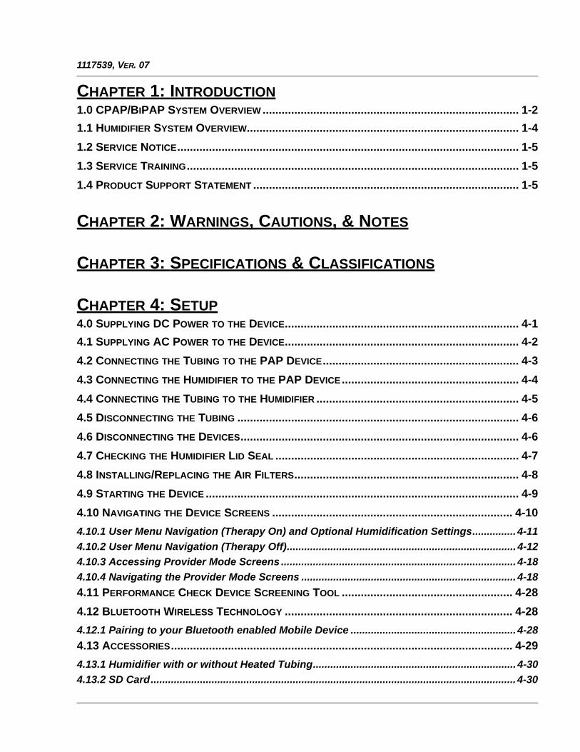
CHAPTER 1: INTRODUCTION1.0 CPAP/BIPAP SYSTEM OVERVIEW ................................................................................. 1-2
1.1 HUMIDIFIER SYSTEM OVERVIEW...................................................................................... 1-4
1.2 SERVICE NOTICE............................................................................................................ 1-5
1.3 SERVICE TRAINING......................................................................................................... 1-5
1.4 PRODUCT SUPPORT STATEMENT .................................................................................... 1-5
CHAPTER 2: WARNINGS, CAUTIONS, & NOTES
CHAPTER 3: SPECIFICATIONS & CLASSIFICATIONS
CHAPTER 4: SETUP4.0 SUPPLYING DC POWER TO THE DEVICE.......................................................................... 4-1
4.1 SUPPLYING AC POWER TO THE DEVICE.......................................................................... 4-2
4.2 CONNECTING THE TUBING TO THE PAP DEVICE.............................................................. 4-3
4.3 CONNECTING THE HUMIDIFIER TO THE PAP DEVICE........................................................ 4-4
4.4 CONNECTING THE TUBING TO THE HUMIDIFIER ................................................................ 4-5
4.5 DISCONNECTING THE TUBING ......................................................................................... 4-6
4.6 DISCONNECTING THE DEVICES........................................................................................ 4-6
4.7 CHECKING THE HUMIDIFIER LID SEAL ............................................................................. 4-7
4.8 INSTALLING/REPLACING THE AIR FILTERS....................................................................... 4-8
4.9 STARTING THE DEVICE ................................................................................................... 4-9
4.10 NAVIGATING THE DEVICE SCREENS ............................................................................ 4-10
4.10.1 User Menu Navigation (Therapy On) and Optional Humidification Settings............... 4-11
4.10.2 User Menu Navigation (Therapy Off)............................................................................... 4-12
4.10.3 Accessing Provider Mode Screens ................................................................................. 4-18
4.10.4 Navigating the Provider Mode Screens .......................................................................... 4-18
4.11 PERFORMANCE CHECK DEVICE SCREENING TOOL ...................................................... 4-28
4.12 BLUETOOTH WIRELESS TECHNOLOGY ........................................................................ 4-28
4.12.1 Pairing to your Bluetooth enabled Mobile Device ......................................................... 4-28
4.13 ACCESSORIES............................................................................................................ 4-29
4.13.1 Humidifier with or without Heated Tubing...................................................................... 4-30
4.13.2 SD Card.............................................................................................................................. 4-30
1117539, VER. 07
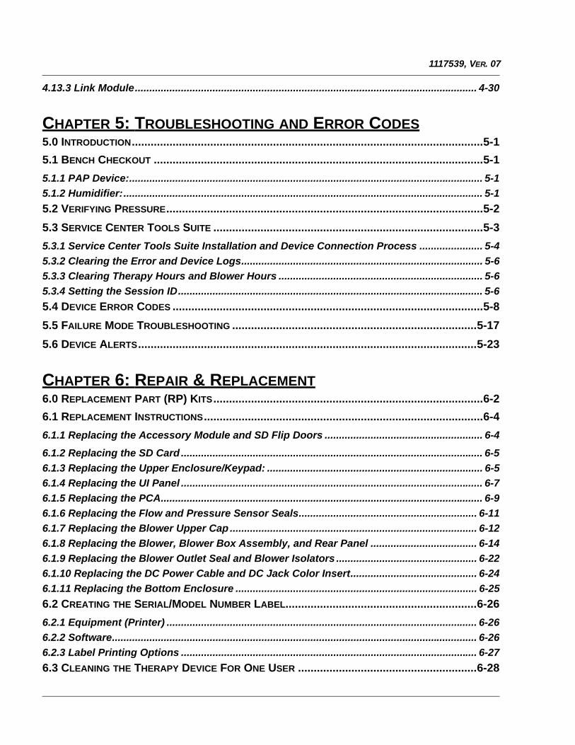
4.13.3 Link Module....................................................................................................................... 4-30
CHAPTER 5: TROUBLESHOOTING AND ERROR CODES5.0 INTRODUCTION................................................................................................................5-1
5.1 BENCH CHECKOUT .........................................................................................................5-1
5.1.1 PAP Device:........................................................................................................................... 5-1
5.1.2 Humidifier:............................................................................................................................. 5-1
5.2 VERIFYING PRESSURE.....................................................................................................5-2
5.3 SERVICE CENTER TOOLS SUITE ......................................................................................5-3
5.3.1 Service Center Tools Suite Installation and Device Connection Process ...................... 5-4
5.3.2 Clearing the Error and Device Logs.................................................................................... 5-6
5.3.3 Clearing Therapy Hours and Blower Hours ....................................................................... 5-6
5.3.4 Setting the Session ID.......................................................................................................... 5-6
5.4 DEVICE ERROR CODES ...................................................................................................5-8
5.5 FAILURE MODE TROUBLESHOOTING ..............................................................................5-17
5.6 DEVICE ALERTS............................................................................................................5-23
CHAPTER 6: REPAIR & REPLACEMENT6.0 REPLACEMENT PART (RP) KITS......................................................................................6-2
6.1 REPLACEMENT INSTRUCTIONS.........................................................................................6-4
6.1.1 Replacing the Accessory Module and SD Flip Doors ....................................................... 6-4
6.1.2 Replacing the SD Card ......................................................................................................... 6-5
6.1.3 Replacing the Upper Enclosure/Keypad: ........................................................................... 6-5
6.1.4 Replacing the UI Panel ......................................................................................................... 6-7
6.1.5 Replacing the PCA................................................................................................................ 6-9
6.1.6 Replacing the Flow and Pressure Sensor Seals.............................................................. 6-11
6.1.7 Replacing the Blower Upper Cap ...................................................................................... 6-12
6.1.8 Replacing the Blower, Blower Box Assembly, and Rear Panel ..................................... 6-14
6.1.9 Replacing the Blower Outlet Seal and Blower Isolators ................................................. 6-22
6.1.10 Replacing the DC Power Cable and DC Jack Color Insert............................................ 6-24
6.1.11 Replacing the Bottom Enclosure .................................................................................... 6-25
6.2 CREATING THE SERIAL/MODEL NUMBER LABEL.............................................................6-26
6.2.1 Equipment (Printer) ............................................................................................................ 6-26
6.2.2 Software............................................................................................................................... 6-26
6.2.3 Label Printing Options ....................................................................................................... 6-27
6.3 CLEANING THE THERAPY DEVICE FOR ONE USER .........................................................6-28

1117539, VER. 07
6.4 CLEANING FOR MULTIPLE USERS ................................................................................. 6-28
6.5 CLEANING OR REPLACING THE FILTERS........................................................................ 6-29
6.6 CLEANING THE TUBING ................................................................................................ 6-30
6.7 PREVENTIVE MAINTENANCE.......................................................................................... 6-30
CHAPTER 7: HUMIDIFIER REPAIR AND REPLACEMENT7.0 HUMIDIFIER REPLACEMENT PART (RP) KITS................................................................... 7-1
7.1 REPLACEMENT INSTRUCTIONS ........................................................................................ 7-2
7.1.1 Replacing the Water Tank Assembly ..................................................................................7-2
7.1.2 Replacing the Flip Lid and Dry Box Inlet Seals.................................................................. 7-3
7.1.3 Replacing the Dry Box Assembly........................................................................................ 7-4
7.1.4 Replacing the Wire Guard .................................................................................................... 7-5
7.1.5 Replacing the Back Panel Assembly ..................................................................................7-8
7.1.6 Replacing the Flip Lid Latch ................................................................................................ 7-9
7.1.7 Replacing the Lifting Tray.................................................................................................. 7-10
7.1.8 Replacing the Bottom Cover.............................................................................................. 7-13
7.1.9 Replacing the Heat Shield.................................................................................................. 7-14
7.1.10 Replacing the Heater Plate O-Ring.................................................................................. 7-15
7.1.11 Replacing the Bottom/Flip Lid Assembly ....................................................................... 7-16
7.2 CLEANING THE WATER TANK ....................................................................................... 7-21
7.3 CLEANING THE HUMIDIFIER BASE ................................................................................. 7-21
7.4 CLEANING THE HEATED TUBING ................................................................................... 7-22
7.5 HOSPITAL AND INSTITUTION DISINFECTION: WATER TANK, SEAL AND HEATED TUBING.. 7-22
7.5.1 Cleaning Prior to Disinfection ...........................................................................................7-22
7.5.2 Disinfection ......................................................................................................................... 7-23
7.5.3 After Disinfection ................................................................................................................ 7-23
CHAPTER 8: TESTING AND CALIBRATION8.1 REQUIRED EQUIPMENT................................................................................................... 8-1
8.2 TESTING PREREQUISITES ............................................................................................... 8-2
8.3 TESTING ENVIRONMENT SPECIFICATIONS........................................................................ 8-2
8.4 FINAL TESTING PROCEDURE........................................................................................... 8-2

1117539, VER. 07
This page intentionally blank.

PAGE 1-11117539, VER. 07
© 2016 Koninklijke Philips N.V. All rights reserved.
PAGE 1-2 1117539, VER. 07
CHAPTER 1: INTRODUCTION
1.0 CPAP/BIPAP SYSTEM OVERVIEW
The DreamStation CPAP is a Continuous Positive Airway Pressure therapy device designed for the treatmentof Obstructive Sleep Apnea (OSA). The DreamStation CPAP Pro can also deliver CPAP-check therapy, andthe DreamStation Auto CPAP can also deliver CPAP-Check and Auto-CPAP therapy.
The DreamStation BiPAP Pro can be set up as a Bi-level device, which delivers two different positive pressurelevels: IPAP (Inspiratory Positive Airway Pressure) and EPAP (Expiratory Positive Airway Pressure). TheDreamStation BiPAP Auto can also be set up as an Auto Bi-level device. Both BiPAP systems can also be setup as a CPAP (Continuous Positive Airway Pressure) device.
CAUTION
U.S. federal law restricts this device to sale by or onthe order of a physician.
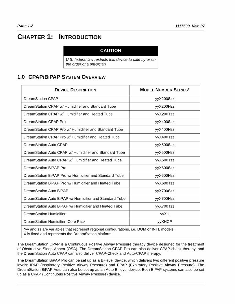
DEVICE DESCRIPTION MODEL NUMBER SERIES*
DreamStation CPAP yyX200Szz
DreamStation CPAP w/ Humidifier and Standard Tube yyX200Hzz
DreamStation CPAP w/ Humidifier and Heated Tube yyX200Tzz
DreamStation CPAP Pro yyX400Szz
DreamStation CPAP Pro w/ Humidifier and Standard Tube yyX400Hzz
DreamStation CPAP Pro w/ Humidifier and Heated Tube yyX400Tzz
DreamStation Auto CPAP yyX500Szz
DreamStation Auto CPAP w/ Humidifier and Standard Tube yyX500Hzz
DreamStation Auto CPAP w/ Humidifier and Heated Tube yyX500Tzz
DreamStation BiPAP Pro yyX600Szz
DreamStation BiPAP Pro w/ Humidifier and Standard Tube yyX600Hzz
DreamStation BiPAP Pro w/ Humidifier and Heated Tube yyX600Tzz
DreamStation Auto BiPAP yyX700Szz
DreamStation Auto BiPAP w/ Humidifier and Standard Tube yyX700Hzz
DreamStation Auto BiPAP w/ Humidifier and Heated Tube yyX700Tzz
DreamStation Humidifier yyXH
DreamStation Humidifier, Core Pack yyXHCP
*yy and zz are variables that represent regional configurations, i.e. DOM or INTL models.X is fixed and represents the DreamStation platform.
PAGE 1-31117539, VER. 07
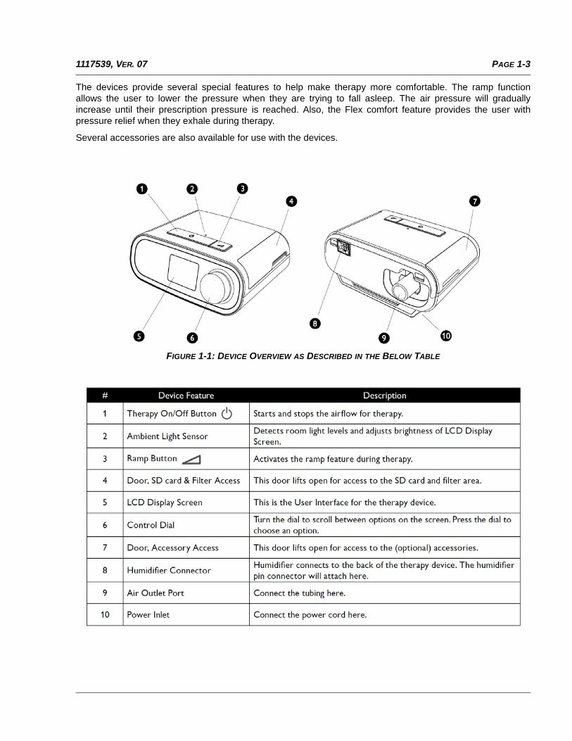
The devices provide several special features to help make therapy more comfortable. The ramp functionallows the user to lower the pressure when they are trying to fall asleep. The air pressure will graduallyincrease until their prescription pressure is reached. Also, the Flex comfort feature provides the user withpressure relief when they exhale during therapy.
Several accessories are also available for use with the devices.
FIGURE 1-1: DEVICE OVERVIEW AS DESCRIBED IN THE BELOW TABLE
PAGE 1-4 1117539, VER. 07
1.1 HUMIDIFIER SYSTEM OVERVIEW
The DreamStation Heated Humidifier attaches to the therapy device and provides an air outlet port to connecta breathing circuit. The breathing circuit is comprised of patient tubing, a mask, and in some instances aseparate exhalation device. The patient tubing can be Respironics heated tubing, 22 mm (non-heated)performance tubing or 15 mm (non-heated) performance tubing.
The DreamStation Heated Humidifier with Heated Tubing is designed to deliver humidification to provide addedcomfort during therapy. This humidification level is controlled through the output of the heated humidifier aswell as the temperature of the optional heated tubing. Use of these two accessories allows for a comfortablelevel of humidity to be maintained at the mask.
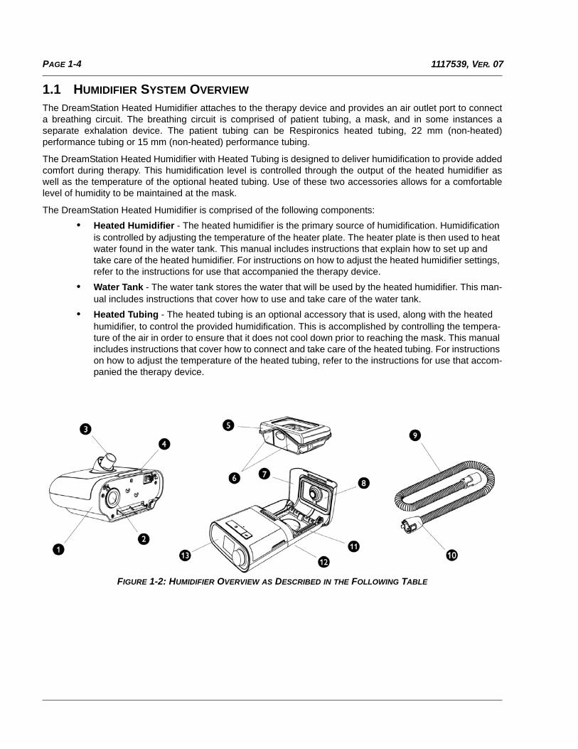
The DreamStation Heated Humidifier is comprised of the following components:
• Heated Humidifier - The heated humidifier is the primary source of humidification. Humidificationis controlled by adjusting the temperature of the heater plate. The heater plate is then used to heatwater found in the water tank. This manual includes instructions that explain how to set up andtake care of the heated humidifier. For instructions on how to adjust the heated humidifier settings,refer to the instructions for use that accompanied the therapy device.
• Water Tank - The water tank stores the water that will be used by the heated humidifier. This man-ual includes instructions that cover how to use and take care of the water tank.
• Heated Tubing - The heated tubing is an optional accessory that is used, along with the heatedhumidifier, to control the provided humidification. This is accomplished by controlling the tempera-ture of the air in order to ensure that it does not cool down prior to reaching the mask. This manualincludes instructions that cover how to connect and take care of the heated tubing. For instructionson how to adjust the temperature of the heated tubing, refer to the instructions for use that accom-panied the therapy device.
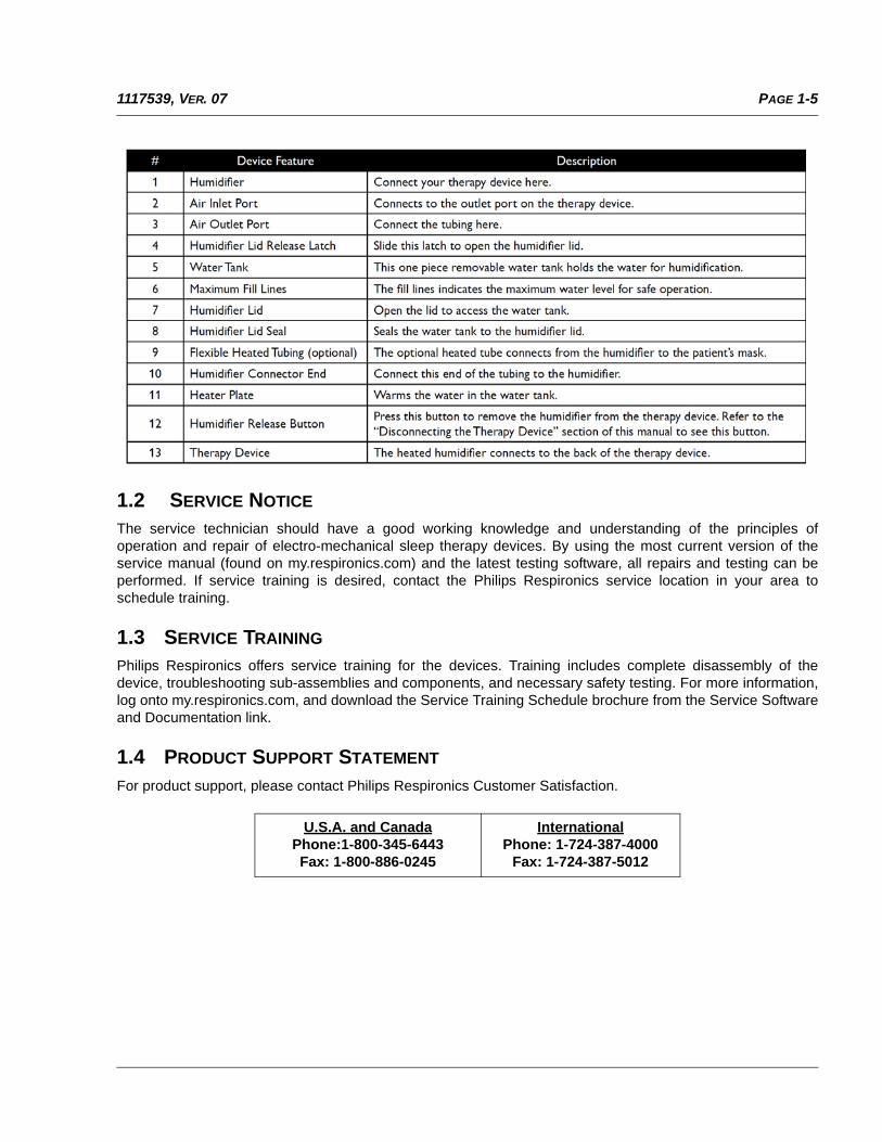
FIGURE 1-2: HUMIDIFIER OVERVIEW AS DESCRIBED IN THE FOLLOWING TABLE
PAGE 1-51117539, VER. 07
1.2 SERVICE NOTICE
The service technician should have a good working knowledge and understanding of the principles ofoperation and repair of electro-mechanical sleep therapy devices. By using the most current version of theservice manual (found on my.respironics.com) and the latest testing software, all repairs and testing can beperformed. If service training is desired, contact the Philips Respironics service location in your area toschedule training.
1.3 SERVICE TRAINING
Philips Respironics offers service training for the devices. Training includes complete disassembly of thedevice, troubleshooting sub-assemblies and components, and necessary safety testing. For more information,log onto my.respironics.com, and download the Service Training Schedule brochure from the Service Softwareand Documentation link.
1.4 PRODUCT SUPPORT STATEMENT
For product support, please contact Philips Respironics Customer Satisfaction.
U.S.A. and CanadaPhone:1-800-345-6443Fax: 1-800-886-0245
InternationalPhone: 1-724-387-4000
Fax: 1-724-387-5012

PAGE 1-6 1117539, VER. 07
This page intentionally blank.
PAGE 2-11117539, VER. 07
CHAPTER 2: WARNINGS, CAUTIONS, & NOTES
Warnings, cautions, and notes are used throughout this manual to identify possible safety hazards, conditionsthat may result in equipment or property damage, and important information that must be considered whenperforming service and testing procedures on the device.
Refer to the devices’ User and Provider Manuals for warnings, cautions and notes.
WARNING
Warnings indicate the possibility of injury to people.
CAUTION
Cautions indicate the possibility of damage to equipment.
NOTE
Notes are used to emphasize a characteristic orimportant consideration.
TABLE 2-1: USER & PROVIDER MANUALS
DESCRIPTION PART NUMBER
DreamStation CPAP, User Manual, EN-INTL CE 1121981
DreamStation BiPAP, User Manual, EN-INTL CE 1121982
DreamStation Humid, User Manual, EN-INTL CE 1121984
DreamStation, Provider Guide, EN-INTL CE 1121983

PAGE 2-2 1117539, VER. 07
This page intentionally blank.
PAGE 3-11117539, VER. 07
CHAPTER 3: SPECIFICATIONS & CLASSIFICATIONS
Refer to the devices’ User and Provider Manuals for specifications and classifications.
TABLE 3-1: USER & PROVIDER MANUALS
DESCRIPTION PART NUMBER
DreamStation CPAP, User Manual, EN-INTL CE 1121981
DreamStation BiPAP, User Manual, EN-INTL CE 1121982
DreamStation Humid, User Manual, EN-INTL CE 1121984
DreamStation, Provider Guide, EN-INTL CE 1121983

PAGE 3-2 1117539, VER. 07
This page intentionally blank.
PAGE 4-11117539, VER. 07
CHAPTER 4: SETUP
This chapter provides an overview of the system setup including introductory information on the User andProvider modes and menus. Please refer to the device’s User Manual for further information.
4.0 SUPPLYING DC POWER TO THE DEVICE
A Philips Respironics DC power cord can be used to operate this device in a stationary recreational vehicle,boat, or motor home. In addition, a Philips Respironics DC battery adapter cable, when used with a DC powercord, allows the device to be operated from a 12 VDC free-standing battery.
WARNING
• Inspect the power cord often for any signs of damage.Replace a damaged power cord immediately.
• Be sure to route the power cord to the outlet in a way thatwill prevent the cord from being tripped over or interferedwith by chairs or other furniture.
• This device is activated when the power cord is connected.
CAUTION
• If the device has been exposed to either very hot or verycold temperatures, allow it to adjust to room temperature(approximately two hours) before beginning setup.
• Do not use extension cords with this device.
NOTE
• Please refer to the Clinical Manual for additional information.
CAUTION
• Always ensure that the DC power cord securely fits into the therapy device prior to use.
• When DC power is obtained from a vehicle battery, the device should not be used while thevehicle’s engine is running. Damage to the device may occur.
• Only use a Philips Respironics DC Power Cord and Battery Adapter Cable. Use of anyother system may cause damage to the device.
PAGE 4-2 1117539, VER. 07
4.1 SUPPLYING AC POWER TO THE DEVICE
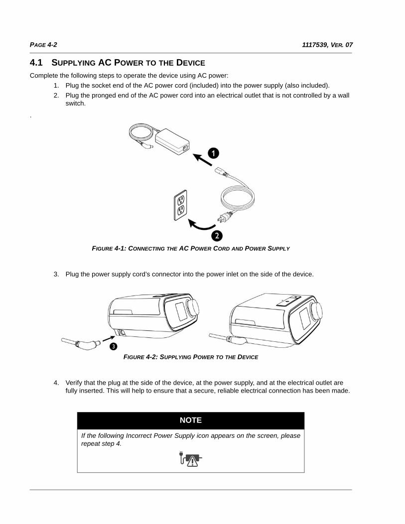
Complete the following steps to operate the device using AC power:
1. Plug the socket end of the AC power cord (included) into the power supply (also included).
2. Plug the pronged end of the AC power cord into an electrical outlet that is not controlled by a wall switch.
.
FIGURE 4-1: CONNECTING THE AC POWER CORD AND POWER SUPPLY
3. Plug the power supply cord’s connector into the power inlet on the side of the device.
FIGURE 4-2: SUPPLYING POWER TO THE DEVICE
4. Verify that the plug at the side of the device, at the power supply, and at the electrical outlet are fully inserted. This will help to ensure that a secure, reliable electrical connection has been made.
NOTE
If the following Incorrect Power Supply icon appears on the screen, pleaserepeat step 4.
PAGE 4-31117539, VER. 07
4.2 CONNECTING THE TUBING TO THE PAP DEVICE
To connect the Tubing to the device, complete the following steps:
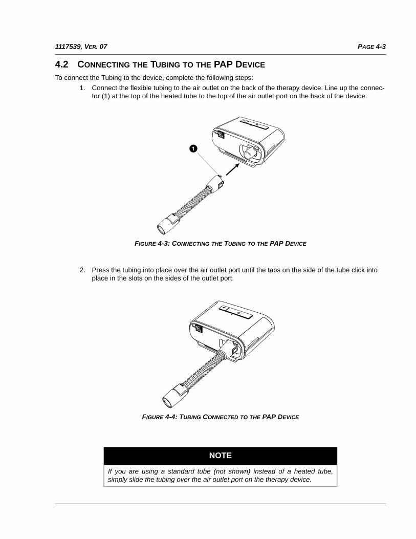
1. Connect the flexible tubing to the air outlet on the back of the therapy device. Line up the connec-tor (1) at the top of the heated tube to the top of the air outlet port on the back of the device.
FIGURE 4-3: CONNECTING THE TUBING TO THE PAP DEVICE
2. Press the tubing into place over the air outlet port until the tabs on the side of the tube click into place in the slots on the sides of the outlet port.
FIGURE 4-4: TUBING CONNECTED TO THE PAP DEVICE
NOTE
If you are using a standard tube (not shown) instead of a heated tube,simply slide the tubing over the air outlet port on the therapy device.
PAGE 4-4 1117539, VER. 07
4.3 CONNECTING THE HUMIDIFIER TO THE PAP DEVICE
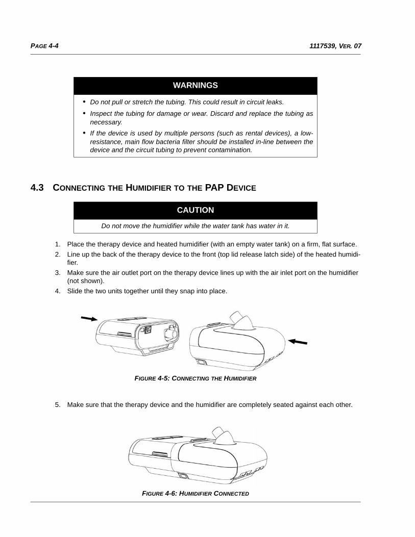
1. Place the therapy device and heated humidifier (with an empty water tank) on a firm, flat surface.
2. Line up the back of the therapy device to the front (top lid release latch side) of the heated humidi-fier.
3. Make sure the air outlet port on the therapy device lines up with the air inlet port on the humidifier (not shown).
4. Slide the two units together until they snap into place.
FIGURE 4-5: CONNECTING THE HUMIDIFIER
5. Make sure that the therapy device and the humidifier are completely seated against each other.
FIGURE 4-6: HUMIDIFIER CONNECTED
WARNINGS
• Do not pull or stretch the tubing. This could result in circuit leaks.
• Inspect the tubing for damage or wear. Discard and replace the tubing asnecessary.
• If the device is used by multiple persons (such as rental devices), a low-resistance, main flow bacteria filter should be installed in-line between thedevice and the circuit tubing to prevent contamination.
CAUTION
Do not move the humidifier while the water tank has water in it.
PAGE 4-51117539, VER. 07
4.4 CONNECTING THE TUBING TO THE HUMIDIFIER
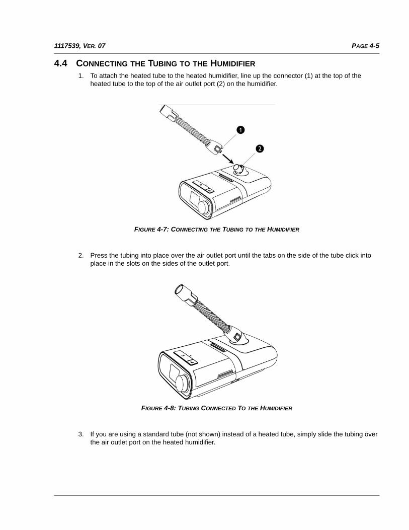
1. To attach the heated tube to the heated humidifier, line up the connector (1) at the top of the heated tube to the top of the air outlet port (2) on the humidifier.
FIGURE 4-7: CONNECTING THE TUBING TO THE HUMIDIFIER
2. Press the tubing into place over the air outlet port until the tabs on the side of the tube click into place in the slots on the sides of the outlet port.
FIGURE 4-8: TUBING CONNECTED TO THE HUMIDIFIER
3. If you are using a standard tube (not shown) instead of a heated tube, simply slide the tubing over the air outlet port on the heated humidifier.
PAGE 4-6 1117539, VER. 07
4.5 DISCONNECTING THE TUBING
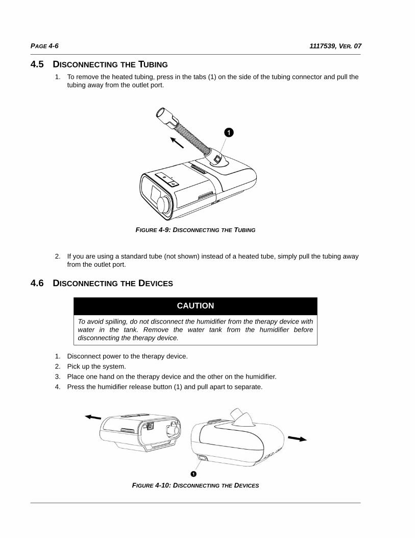
1. To remove the heated tubing, press in the tabs (1) on the side of the tubing connector and pull the tubing away from the outlet port.
FIGURE 4-9: DISCONNECTING THE TUBING
2. If you are using a standard tube (not shown) instead of a heated tube, simply pull the tubing away from the outlet port.
4.6 DISCONNECTING THE DEVICES
1. Disconnect power to the therapy device.
2. Pick up the system.
3. Place one hand on the therapy device and the other on the humidifier.
4. Press the humidifier release button (1) and pull apart to separate.
FIGURE 4-10: DISCONNECTING THE DEVICES
CAUTION
To avoid spilling, do not disconnect the humidifier from the therapy device withwater in the tank. Remove the water tank from the humidifier beforedisconnecting the therapy device.
PAGE 4-71117539, VER. 07
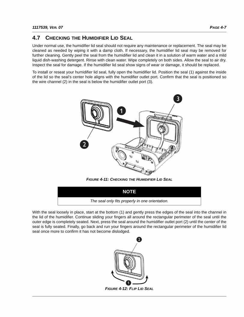
4.7 CHECKING THE HUMIDIFIER LID SEAL
Under normal use, the humidifier lid seal should not require any maintenance or replacement. The seal may becleaned as needed by wiping it with a damp cloth. If necessary, the humidifier lid seal may be removed forfurther cleaning. Gently peel the seal from the humidifier lid and clean it in a solution of warm water and a mildliquid dish-washing detergent. Rinse with clean water. Wipe completely on both sides. Allow the seal to air dry.Inspect the seal for damage. If the humidifier lid seal show signs of wear or damage, it should be replaced.
To install or reseat your humidifier lid seal, fully open the humidifier lid. Position the seal (1) against the insideof the lid so the seal’s center hole aligns with the humidifier outlet port. Confirm that the seal is positioned sothe wire channel (2) in the seal is below the humidifier outlet port (3).
FIGURE 4-11: CHECKING THE HUMIDIFIER LID SEAL
With the seal loosely in place, start at the bottom (1) and gently press the edges of the seal into the channel inthe lid of the humidifier. Continue sliding your fingers all around the rectangular perimeter of the seal until theouter edge is completely seated. Next, press the seal around the humidifier outlet port (2) until the center of theseal is fully seated. Finally, go back and run your fingers around the rectangular perimeter of the humidifier lidseal once more to confirm it has not become dislodged.
FIGURE 4-12: FLIP LID SEAL
NOTE
The seal only fits properly in one orientation.
PAGE 4-8 1117539, VER. 07
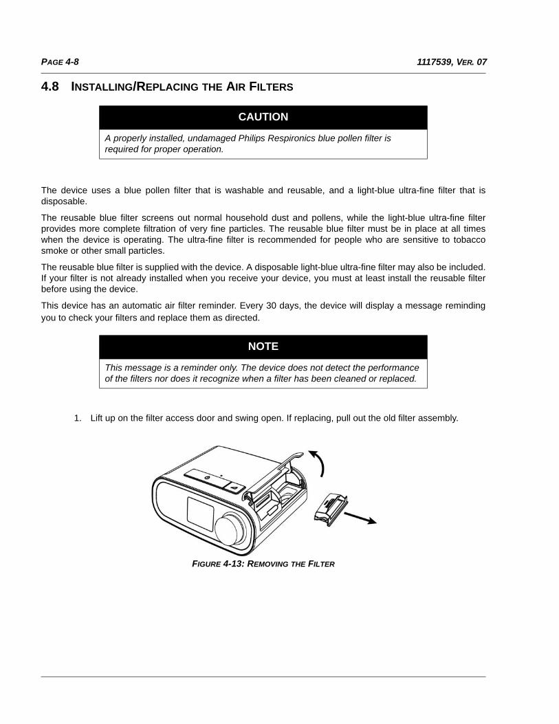
4.8 INSTALLING/REPLACING THE AIR FILTERS
The device uses a blue pollen filter that is washable and reusable, and a light-blue ultra-fine filter that isdisposable.
The reusable blue filter screens out normal household dust and pollens, while the light-blue ultra-fine filterprovides more complete filtration of very fine particles. The reusable blue filter must be in place at all timeswhen the device is operating. The ultra-fine filter is recommended for people who are sensitive to tobaccosmoke or other small particles.
The reusable blue filter is supplied with the device. A disposable light-blue ultra-fine filter may also be included.If your filter is not already installed when you receive your device, you must at least install the reusable filterbefore using the device.
This device has an automatic air filter reminder. Every 30 days, the device will display a message remindingyou to check your filters and replace them as directed.
1. Lift up on the filter access door and swing open. If replacing, pull out the old filter assembly.
FIGURE 4-13: REMOVING THE FILTER
CAUTION
A properly installed, undamaged Philips Respironics blue pollen filter is required for proper operation.
NOTE
This message is a reminder only. The device does not detect the performance of the filters nor does it recognize when a filter has been cleaned or replaced.
PAGE 4-91117539, VER. 07
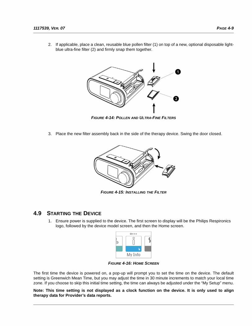
2. If applicable, place a clean, reusable blue pollen filter (1) on top of a new, optional disposable light-blue ultra-fine filter (2) and firmly snap them together.
FIGURE 4-14: POLLEN AND ULTRA-FINE FILTERS
3. Place the new filter assembly back in the side of the therapy device. Swing the door closed.
FIGURE 4-15: INSTALLING THE FILTER
4.9 STARTING THE DEVICE
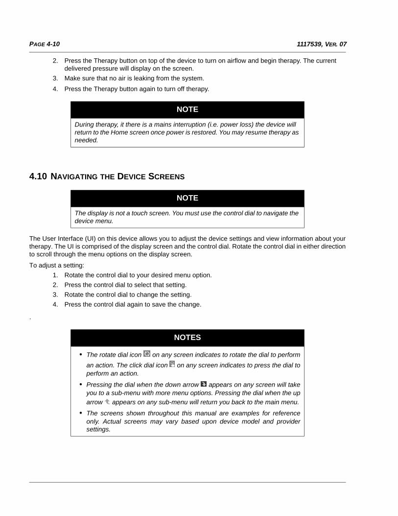
1. Ensure power is supplied to the device. The first screen to display will be the Philips Respironics logo, followed by the device model screen, and then the Home screen.
FIGURE 4-16: HOME SCREEN
The first time the device is powered on, a pop-up will prompt you to set the time on the device. The defaultsetting is Greenwich Mean Time, but you may adjust the time in 30 minute increments to match your local timezone. If you choose to skip this initial time setting, the time can always be adjusted under the “My Setup” menu.
Note: This time setting is not displayed as a clock function on the device. It is only used to aligntherapy data for Provider’s data reports.
PAGE 4-10 1117539, VER. 07
2. Press the Therapy button on top of the device to turn on airflow and begin therapy. The current delivered pressure will display on the screen.
3. Make sure that no air is leaking from the system.
4. Press the Therapy button again to turn off therapy.
4.10 NAVIGATING THE DEVICE SCREENS
The User Interface (UI) on this device allows you to adjust the device settings and view information about yourtherapy. The UI is comprised of the display screen and the control dial. Rotate the control dial in either directionto scroll through the menu options on the display screen.
To adjust a setting:
1. Rotate the control dial to your desired menu option.
2. Press the control dial to select that setting.
3. Rotate the control dial to change the setting.
4. Press the control dial again to save the change.
.
NOTE
During therapy, it there is a mains interruption (i.e. power loss) the device will return to the Home screen once power is restored. You may resume therapy as needed.
NOTE
The display is not a touch screen. You must use the control dial to navigate the device menu.
NOTES
• The rotate dial icon on any screen indicates to rotate the dial to perform
an action. The click dial icon on any screen indicates to press the dial toperform an action.
• Pressing the dial when the down arrow appears on any screen will takeyou to a sub-menu with more menu options. Pressing the dial when the up
arrow appears on any sub-menu will return you back to the main menu.
• The screens shown throughout this manual are examples for referenceonly. Actual screens may vary based upon device model and providersettings.
PAGE 4-111117539, VER. 07
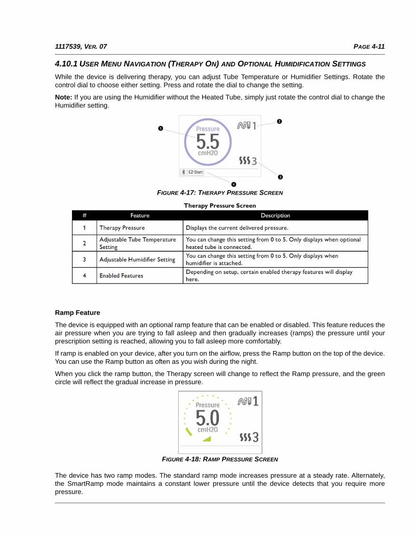
4.10.1 USER MENU NAVIGATION (THERAPY ON) AND OPTIONAL HUMIDIFICATION SETTINGS
While the device is delivering therapy, you can adjust Tube Temperature or Humidifier Settings. Rotate thecontrol dial to choose either setting. Press and rotate the dial to change the setting.
Note: If you are using the Humidifier without the Heated Tube, simply just rotate the control dial to change theHumidifier setting.
FIGURE 4-17: THERAPY PRESSURE SCREEN
Ramp Feature
The device is equipped with an optional ramp feature that can be enabled or disabled. This feature reduces theair pressure when you are trying to fall asleep and then gradually increases (ramps) the pressure until yourprescription setting is reached, allowing you to fall asleep more comfortably.
If ramp is enabled on your device, after you turn on the airflow, press the Ramp button on the top of the device.You can use the Ramp button as often as you wish during the night.
When you click the ramp button, the Therapy screen will change to reflect the Ramp pressure, and the greencircle will reflect the gradual increase in pressure.
FIGURE 4-18: RAMP PRESSURE SCREEN
The device has two ramp modes. The standard ramp mode increases pressure at a steady rate. Alternately,the SmartRamp mode maintains a constant lower pressure until the device detects that you require morepressure.
PAGE 4-12 1117539, VER. 07
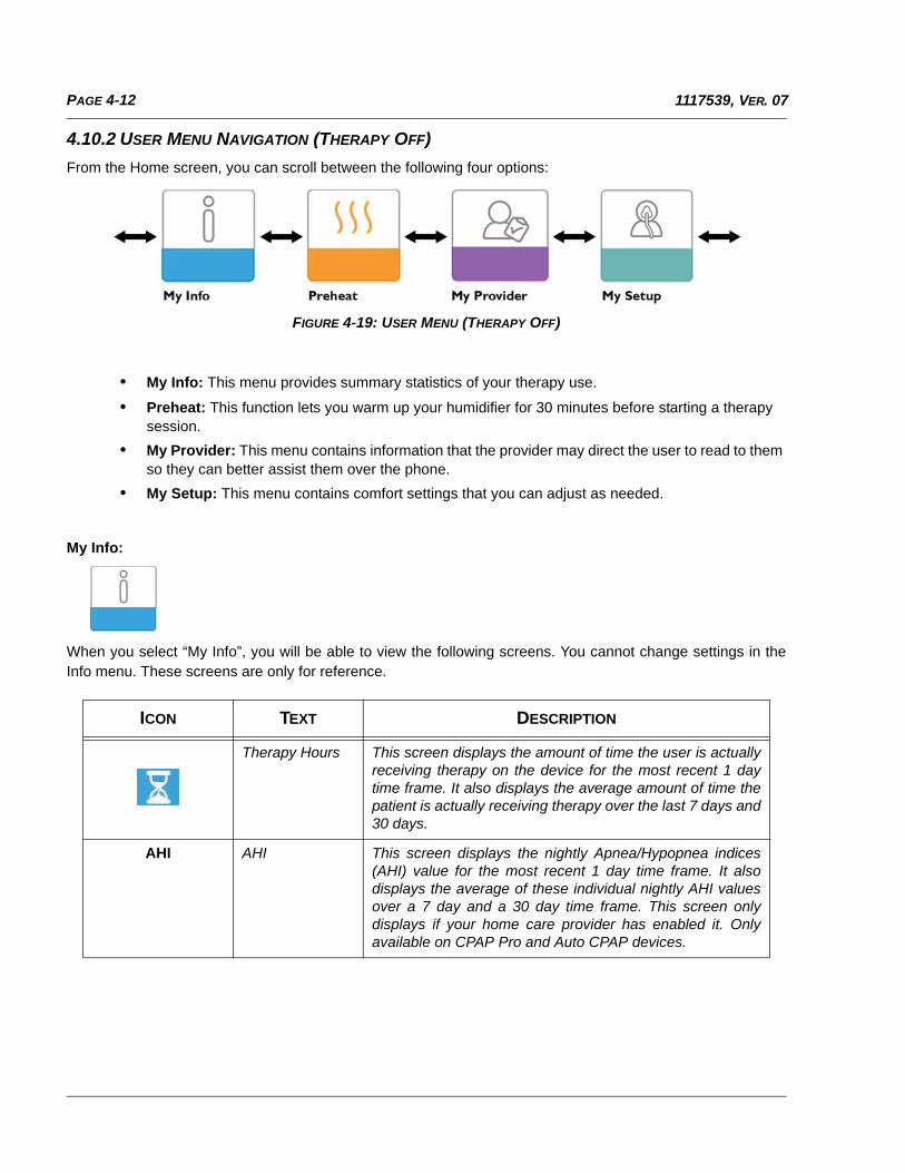
4.10.2 USER MENU NAVIGATION (THERAPY OFF)
From the Home screen, you can scroll between the following four options:
FIGURE 4-19: USER MENU (THERAPY OFF)
• My Info: This menu provides summary statistics of your therapy use.
• Preheat: This function lets you warm up your humidifier for 30 minutes before starting a therapy session.
• My Provider: This menu contains information that the provider may direct the user to read to them so they can better assist them over the phone.
• My Setup: This menu contains comfort settings that you can adjust as needed.
My Info:
When you select “My Info”, you will be able to view the following screens. You cannot change settings in theInfo menu. These screens are only for reference.
ICON TEXT DESCRIPTION
Therapy Hours This screen displays the amount of time the user is actuallyreceiving therapy on the device for the most recent 1 daytime frame. It also displays the average amount of time thepatient is actually receiving therapy over the last 7 days and30 days.
AHI AHI This screen displays the nightly Apnea/Hypopnea indices(AHI) value for the most recent 1 day time frame. It alsodisplays the average of these individual nightly AHI valuesover a 7 day and a 30 day time frame. This screen onlydisplays if your home care provider has enabled it. Onlyavailable on CPAP Pro and Auto CPAP devices.
PAGE 4-131117539, VER. 07
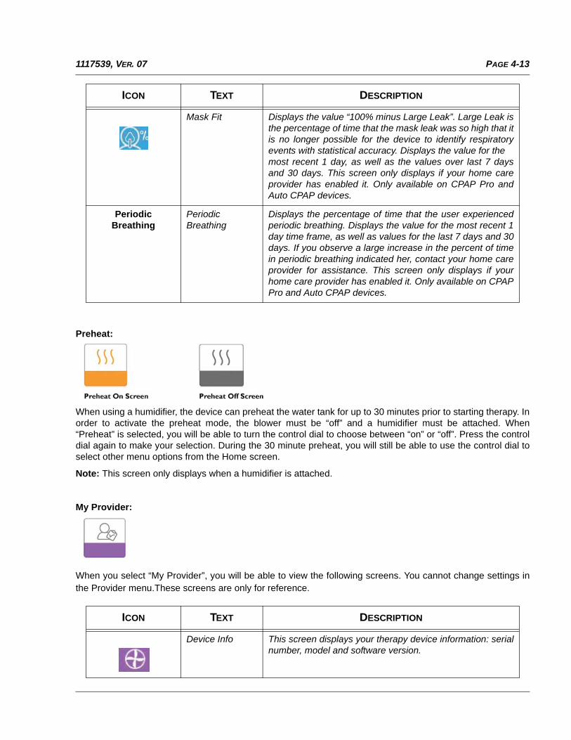
Preheat:
When using a humidifier, the device can preheat the water tank for up to 30 minutes prior to starting therapy. Inorder to activate the preheat mode, the blower must be “off” and a humidifier must be attached. When“Preheat” is selected, you will be able to turn the control dial to choose between “on” or “off”. Press the controldial again to make your selection. During the 30 minute preheat, you will still be able to use the control dial toselect other menu options from the Home screen.
Note: This screen only displays when a humidifier is attached.
My Provider:
When you select “My Provider”, you will be able to view the following screens. You cannot change settings inthe Provider menu.These screens are only for reference.
Mask Fit Displays the value “100% minus Large Leak”. Large Leak isthe percentage of time that the mask leak was so high that itis no longer possible for the device to identify respiratoryevents with statistical accuracy. Displays the value for themost recent 1 day, as well as the values over last 7 daysand 30 days. This screen only displays if your home careprovider has enabled it. Only available on CPAP Pro andAuto CPAP devices.
Periodic Breathing
PeriodicBreathing
Displays the percentage of time that the user experiencedperiodic breathing. Displays the value for the most recent 1day time frame, as well as values for the last 7 days and 30days. If you observe a large increase in the percent of timein periodic breathing indicated her, contact your home careprovider for assistance. This screen only displays if yourhome care provider has enabled it. Only available on CPAPPro and Auto CPAP devices.
ICON TEXT DESCRIPTION
Device Info This screen displays your therapy device information: serialnumber, model and software version.
ICON TEXT DESCRIPTION
PAGE 4-14 1117539, VER. 07
Provider ContactInfo
This screen will display the contact information for yourprovider if it has been uploaded to your device.
Phone-In This screen displays the total therapy hours for the device,the total blower hours, the total number of days used whenthe sessions were greater than 4 hours, and a compliancecheck number used by your home care provider to validatethat the data provided by you is the data taken from thisscreen.
Compliance This screen displays your start date, the total number ofdays used when the sessions were greater than 4 hours,and a check code number used by your home careprovider.
VIC90 VIC 90 This Visual Inspection Check screen will display a checkcode number created from information gathered over themost recent 90 day period. This 15 digit number will displayas: xxx.xxxx.xxxx.xxxx. Your home care provider mayperiodically ask you for this information.
A-TRIAL A-Trial If Auto-Trial mode is available, this screen displays Days:xx/xx (where xx/xx is the number of accumulated trial days /number of selected trial days). Available on the Pro, Auto,BiPAP Pro, and BiPAP Auto models.
90%Pressure
90% Pressure This screen displays the nightly value of 90% Pressure forthe most recent 1 day time frame. It also displays theaverage of these individual nightly values of 90% Pressureover a 7 day and a 30 day time frame. Available on the Automodel.
IPAP: 90%Pressure
IPAP: 90%Pressure
Displays the value of 90% inhalation pressure for the mostrecent 1 day, as well as the average values over the last 7days and 30 days. Available on the BiPAP Auto model.
EPAP: 90%Pressure
EPAP: 90%Pressure
Displays the value of 90% exhalation pressure for the mostrecent 1 day, as well as the average values over the last 7days and 30 days. Available on the BiPAP Auto model.
Upload Allows user to initiate a modem call when an optionalCellular or Wi-Fi Accessory is installed. After the modemupload has finished, the screen will either display a greencheckmark with the text “Completed” to indicate asuccessful upload, or a red X with the text “Failed” toindicate an unsuccessful upload. If the upload fails, initiatean upload a second time, or contact your home careprovider if the issue persists. This screen is locked ifmodem is off.
ICON TEXT DESCRIPTION
PAGE 4-151117539, VER. 07
My Setup:
When you select “My Setup”, you will be able to view the following screens. You can change the settings in theSetup menu. These screens will only display if they are available and enabled on the device.
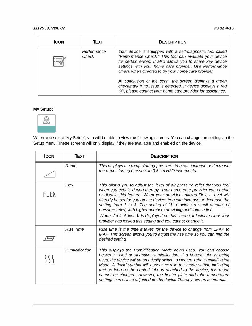
PerformanceCheck
Your device is equipped with a self-diagnostic tool called“Performance Check.” This tool can evaluate your devicefor certain errors. It also allows you to share key devicesettings with your home care provider. Use PerformanceCheck when directed to by your home care provider.
At conclusion of the scan, the screen displays a greencheckmark if no issue is detected. If device displays a red“X”, please contact your home care provider for assistance.
ICON TEXT DESCRIPTION
Ramp This displays the ramp starting pressure. You can increase or decreasethe ramp starting pressure in 0.5 cm H2O increments.
Flex This allows you to adjust the level of air pressure relief that you feelwhen you exhale during therapy. Your home care provider can enableor disable this feature. When your provider enables Flex, a level willalready be set for you on the device. You can increase or decrease thesetting from 1 to 3. The setting of “1” provides a small amount ofpressure relief, with higher numbers providing additional relief.
Note: If a lock icon is displayed on this screen, it indicates that yourprovider has locked this setting and you cannot change it.
Rise Time Rise time is the time it takes for the device to change from EPAP toIPAP. This screen allows you to adjust the rise time so you can find thedesired setting.
Humidification This displays the Humidification Mode being used. You can choosebetween Fixed or Adaptive Humidification. If a heated tube is beingused, the device will automatically switch to Heated Tube HumidificationMode. A “lock” symbol will appear next to the mode setting indicatingthat so long as the heated tube is attached to the device, this modecannot be changed. However, the heater plate and tube temperaturesettings can still be adjusted on the device Therapy screen as normal.
ICON TEXT DESCRIPTION
PAGE 4-16 1117539, VER. 07
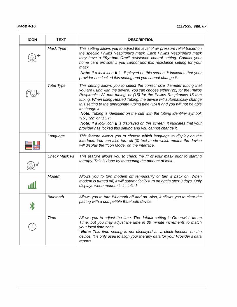
Mask Type This setting allows you to adjust the level of air pressure relief based onthe specific Philips Respironics mask. Each Philips Respironics maskmay have a “System One” resistance control setting. Contact yourhome care provider if you cannot find this resistance setting for yourmask.
Note: If a lock icon is displayed on this screen, it indicates that yourprovider has locked this setting and you cannot change it.
Tube Type This setting allows you to select the correct size diameter tubing thatyou are using with the device. You can choose either (22) for the PhilipsRespironics 22 mm tubing, or (15) for the Philips Respironics 15 mmtubing. When using Heated Tubing, the device will automatically changethis setting to the appropriate tubing type (15H) and you will not be ableto change it. Note: Tubing is identified on the cuff with the tubing identifier symbol:“15”, “22” or “15H”. Note: If a lock icon is displayed on this screen, it indicates that yourprovider has locked this setting and you cannot change it.
Language This feature allows you to choose which language to display on theinterface. You can also turn off (0) text mode which means the devicewill display the “Icon Mode” on the interface.
Check Mask Fit This feature allows you to check the fit of your mask prior to startingtherapy. This is done by measuring the amount of leak.
Modem Allows you to turn modem off temporarily or turn it back on. Whenmodem is turned off, it will automatically turn on again after 3 days. Onlydisplays when modem is installed.
Bluetooth Allows you to turn Bluetooth off and on. Also, it allows you to clear thepairing with a compatible Bluetooth device.
Time Allows you to adjust the time. The default setting is Greenwich MeanTime, but you may adjust the time in 30 minute increments to matchyour local time zone. Note: This time setting is not displayed as a clock function on thedevice. It is only used to align your therapy data for your Provider’s datareports.
ICON TEXT DESCRIPTION

PAGE 4-171117539, VER. 07
Check Mask Fit
The optional check mask fit feature can be enabled or disabled by the home care provider. This feature allowsyou to check the fit of your mask prior to starting therapy. This is done by measuring the amount of leak. Put onyour mask assembly. Refer to your mask instructions if needed. Navigate to the Check Mask Fit screen under“My Setup” and press the control dial to initiate the check.
The device will deliver a test pressure while the screen counts down 40 seconds. A green bar indicates goodfit, while a red bar indicates improvement is needed. After the test, normal therapy will start and the screen willeither display a green checkmark or a red “X”. The green checkmark indicates that the leak found allows foroptimal performance of the device. The red “X” indicates that the leak may affect device performance,however, the device will remain functional and deliver therapy.
FIGURE 4-20: CHECK MASK FIT SCREEN
Sleep Progress
The device provides summary information about therapy use each time the therapy is turned off. The firstscreen displays “Three Night Summary.” It shows nightly usage for the last 3 sleep sessions (measured in 24hour periods, ending at noon each day). The most recent session is displayed in the right hand bar, labeledwith the number of hours slept. A green bar indicates that the person slept more than 4 hours, and a yellow barindicates less than 4 hours of use.
The second screen shows the total number of 4+ hour nights that the person had slept in the last 30 days. Itprovides a goal of sleeping at least 4 hours per night for 70% of the last 30 nights. Therefore the goal is 21“good nights” of use. This screen provides a simple way to track progress. The screen will stop displayingwhen the goal is reached, or after the first 90 days of use has passed, whichever comes first.
Altitude Compensation
This device automatically compensates for altitude up to 7,500 feet. No manual adjustment is necessary.
PAGE 4-18 1117539, VER. 07
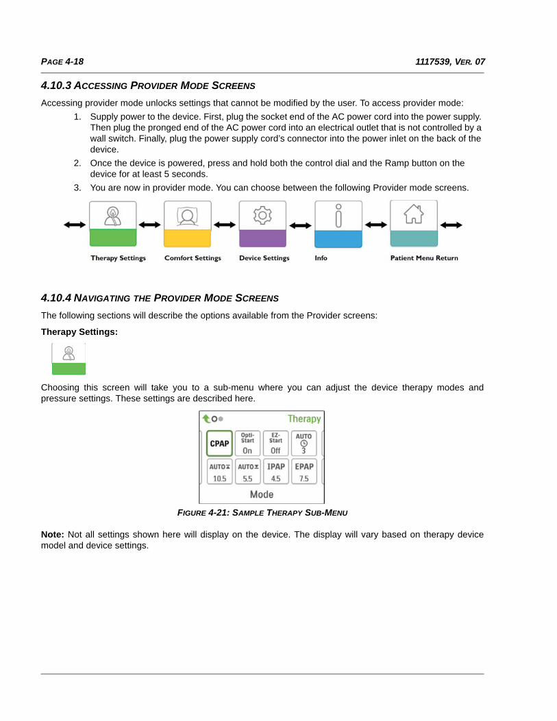
4.10.3 ACCESSING PROVIDER MODE SCREENS
Accessing provider mode unlocks settings that cannot be modified by the user. To access provider mode:
1. Supply power to the device. First, plug the socket end of the AC power cord into the power supply. Then plug the pronged end of the AC power cord into an electrical outlet that is not controlled by a wall switch. Finally, plug the power supply cord’s connector into the power inlet on the back of the device.
2. Once the device is powered, press and hold both the control dial and the Ramp button on the device for at least 5 seconds.
3. You are now in provider mode. You can choose between the following Provider mode screens.
4.10.4 NAVIGATING THE PROVIDER MODE SCREENS
The following sections will describe the options available from the Provider screens:
Therapy Settings:
Choosing this screen will take you to a sub-menu where you can adjust the device therapy modes andpressure settings. These settings are described here.
FIGURE 4-21: SAMPLE THERAPY SUB-MENU
Note: Not all settings shown here will display on the device. The display will vary based on therapy devicemodel and device settings.
PAGE 4-191117539, VER. 07
ICON TEXT DESCRIPTION
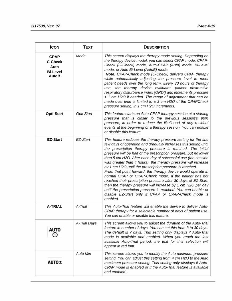
CPAPC-Check
AutoBi-LevelAutoB
Mode This screen displays the therapy mode setting. Depending onthe therapy device model, you can select CPAP mode, CPAP-Check (C-Check) mode, Auto-CPAP (Auto) mode, Bi-Levelmode, or Auto Bi-Level (AutoB) mode. Note: CPAP-Check mode (C-Check) delivers CPAP therapywhile automatically adjusting the pressure level to meetpatient needs over the long term. Every 30 hours of therapyuse, the therapy device evaluates patient obstructiverespiratory disturbance index (ORDI) and increments pressure± 1 cm H2O if needed. The range of adjustment that can bemade over time is limited to ± 3 cm H2O of the CPAPCheckpressure setting, in 1 cm H2O increments.
Opti-Start Opti-Start This feature starts an Auto-CPAP therapy session at a startingpressure that is closer to the previous session’s 90%pressure, in order to reduce the likelihood of any residualevents at the beginning of a therapy session. You can enableor disable this feature.
EZ-Start EZ-Start This feature reduces the therapy pressure setting for the firstfew days of operation and gradually increases this setting untilthe prescription therapy pressure is reached. The initialpressure will be half of the prescription pressure, but no lowerthan 5 cm H2O. After each day of successful use (the sessionwas greater than 4 hours), the therapy pressure will increaseby 1 cm H2O until the prescription pressure is reached.From that point forward, the therapy device would operate innormal CPAP or CPAP-Check mode. If the patient has notreached their prescription pressure after 30 days of EZ-Start,then the therapy pressure will increase by 1 cm H2O per dayuntil the prescription pressure is reached. You can enable ordisable EZ-Start only if CPAP or CPAP-Check mode isenabled.
A-TRIAL A-Trial This Auto-Trial feature will enable the device to deliver Auto-CPAP therapy for a selectable number of days of patient use.You can enable or disable this feature.
A-Trial Days This screen allows you to adjust the duration of the Auto-Trialfeature in number of days. You can set this from 3 to 30 days.The default is 7 days. This setting only displays if Auto-Trialmode is available and enabled. When you reach the lastavailable Auto-Trial period, the text for this selection willappear in red font.
Auto Min This screen allows you to modify the Auto minimum pressuresetting. You can adjust this setting from 4 cm H2O to the Automaximum pressure setting. This setting only displays if Auto-CPAP mode is enabled or if the Auto-Trial feature is availableand enabled.
PAGE 4-20 1117539, VER. 07
Auto Max This screen allows you to modify the Auto maximum pressuresetting. You can adjust this setting from the Auto minimumpressure setting to 20 cm H2O. This screen only displays ifAuto-CPAP mode is enabled or if the Auto-Trial feature isavailable and enabled.
cmH2O Pressure This screen allows you to adjust the CPAP pressure, or theCPAP-Check mode starting pressure. If Auto-Trial mode wasused, you can choose the 90% pressure setting determinedfrom the Auto-Trial mode, or you can adjust this setting from 4to 20 cm H2O. If the Auto-Trial mode was not used, thisscreen allows you to only adjust the pressure setting from 4 to20 cm H2O.
IPAP IPAP This screen allows you to modify the IPAP setting. The initialdefault setting is 20 cm H2O. You can adjust the setting fromthe EPAP setting to 25 cm H2O. This screen only displays ifBi-level mode is enabled.
EPAP EPAP This screen allows you to modify the EPAP setting. The initialdefault setting is 4 cm H2O. You can adjust the setting from 4cm H2O to the IPAP setting. This screen only displays if Bi-level mode is enabled.
IPAP Max This screen allows you to modify the Maximum IPAP setting.The setting you specify here will be the maximum level ofpressure applied during the inspiratory breath phase. You mayadjust the setting from the Minimum EPAP setting to 25 cmH2O. This screen only displays if Auto Bi-level mode isenabled.
EPAP Max This screen allows you to modify the Minimum EPAP setting.The setting specified here will be the minimum level ofpressure applied during the expiratory breath phase. You mayadjust the setting from 4 cm H2O to the Maximum IPAPsetting. This screen only displays if Auto Bi-level mode isenabled.
PS Min This screen allows you to modify the Minimum PressureSupport setting. This setting is the minimum difference that ispermitted between IPAP and EPAP while AutoBi-level therapy mode is active. You may adjust the settingfrom 0 cm H2O to the Maximum Pressure Support setting.This screen only displays if Auto Bi-level mode is enabled.
PS Max This screen allows you to modify the Maximum PressureSupport setting. This setting is the maximum difference that ispermitted between IPAP and EPAP while Auto Bi-level therapymode is active. You may adjust the setting from 0 cm H2O tothe minimum value of either 8 cm H2O, or the differencebetween Max IPAP and Min EPAP. This screen only displays ifAuto Bi-level mode is enabled.
ICON TEXT DESCRIPTION
PAGE 4-211117539, VER. 07
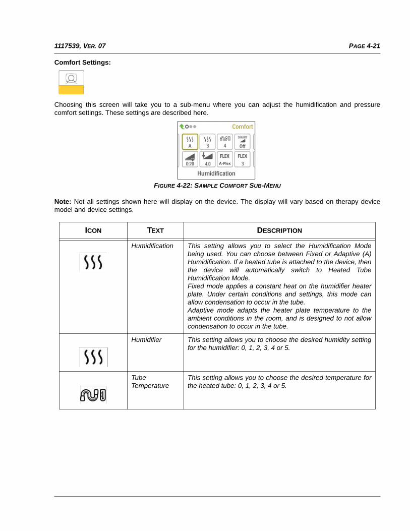
Comfort Settings:
Choosing this screen will take you to a sub-menu where you can adjust the humidification and pressurecomfort settings. These settings are described here.
FIGURE 4-22: SAMPLE COMFORT SUB-MENU
Note: Not all settings shown here will display on the device. The display will vary based on therapy devicemodel and device settings.
ICON TEXT DESCRIPTION
Humidification This setting allows you to select the Humidification Modebeing used. You can choose between Fixed or Adaptive (A)Humidification. If a heated tube is attached to the device, thenthe device will automatically switch to Heated TubeHumidification Mode. Fixed mode applies a constant heat on the humidifier heaterplate. Under certain conditions and settings, this mode canallow condensation to occur in the tube.Adaptive mode adapts the heater plate temperature to theambient conditions in the room, and is designed to not allowcondensation to occur in the tube.
Humidifier This setting allows you to choose the desired humidity settingfor the humidifier: 0, 1, 2, 3, 4 or 5.
TubeTemperature
This setting allows you to choose the desired temperature forthe heated tube: 0, 1, 2, 3, 4 or 5.
PAGE 4-22 1117539, VER. 07
SmartRamp When SmartRamp mode is enabled, the therapy device’sramp function utilizes an Auto titrating algorithm during theramp period. It allows patients the ability to stay at lowerpressures during the ramp period, to improve their acclimationto therapy.SmartRamp mode functions differently, depending on thetherapy mode that the device is using.*In CPAP or CPAP-Check mode, the SmartRamp applies theAuto-CPAP algorithm during the ramp period. The Ramp Startpressure becomes the Auto Minimum pressure during theramp period. The Auto Maximum pressure during ramp is theCPAP or CPAP-Check pressure.*In Auto mode, the SmartRamp applies the Auto-CPAPalgorithm during the ramp period. The Ramp Start pressurebecomes the Auto Minimum pressure during the ramp period.The Auto Maximum pressure during ramp is the AutoMinimum under normal Auto mode.*In BiPAP or Auto-BiPAP mode, the SmartRamp applies the amodified version of the Auto-BiPAP algorithm during the rampperiod. The Ramp Start pressure becomes the EPAPMinimum pressure, and the Pressure Support Minimumpressured is applied.The IPAP Maximum pressure during ramp is the EPAP orEPAP Minimum under normal BiPAP or Auto-BiPAP mode.The SmartRamp period will terminate in either of two ways:1) If SmartRamp pressure reaches the minimum pressure ofthe therapy mode selected, then SmartRamp ends, and thedevice continues to deliver therapy under the selected therapymode, or:2) If SmartRamp pressure does not reach the minimumpressure of the therapy mode selected by the end of theRamp Time, then pressure is increased at a rate ofapproximately 1 cm H2O per minute. Once the pressurereaches the minimum pressure of the therapy mode selected,then the device will continue to deliver therapy for that mode.If SmartRamp mode is not enabled, then the standard, linearpressure ramp mode is active.
Ramp Time When you set the Ramp time, the device increases thetherapy pressure from the value set on the Ramp start screento the therapy pressure setting over the length of timespecified here. If the therapy pressure is set to 4 cm H2O (theminimum setting), this screen will not display. Note: Depending on the therapy mode, the therapy pressuresetting could be CPAP pressure, CPAP-Check pressure, Automin pressure, EPAP pressure, or EPAP min pressure. Note: If the Ramp time is set to 0, Ramp start will not display.
ICON TEXT DESCRIPTION
PAGE 4-231117539, VER. 07
Ramp Start This displays the Ramp starting pressure. You can increase ordecrease the Ramp starting pressure in 0.5 cm H2Oincrements. This is only available if Ramp time has been set to>0 and therapy pressure >4 cm H2O. Note: Depending on the therapy mode, the therapy pressuresetting could be CPAP pressure, CPAP-Check pressure, Automin pressure, EPAP pressure, or EPAP min pressure.
Flex This screen displays the comfort mode setting. You can selectNone, C-Flex, or C-Flex+ (if in CPAP or CPAP-Check mode).You can select None, C-Flex, or A-Flex (if in Auto-CPAP orAuto-Trial mode).
Flex Setting You can modify the Flex setting (1, 2 or 3) on this screen if youenabled Flex. The setting of “1” provides a small amount ofpressure relief, with higher numbers providing additional relief.
Flex Lock This enables you to lock the Flex setting if you do not want thepatient to change it.
Rise Time Rise time is the time it takes for the device to change fromEPAP to IPAP. This screen allows you to adjust the rise timeso you can find the desired setting. This is only available ifFlex has been disabled and the device is in Bi-level or Auto Bi-level mode.• 0 (off) reduces the Rise Time feature to the lowest setting(off = 150 msec).• 1 sets Rise Time to 1 (200 msec).• 2 sets Rise Time to 2 (300 msec).• 3 sets Rise Time to 3 (400 msec).
Rise Time Lock This enables you to lock the Rise Time setting if you do notwant the patient to change it.
Tube Type This setting allows you to select the correct size diametertubing that you are using with the device. You can chooseeither (22) for the Philips Respironics 22 mm tubing, or (15) forthe Philips Respironics 15 mm tubing. When using HeatedTubing, the device will automatically change this setting to theappropriate tubing type (15H).
Tube Type Lock This enables you to lock the Tubing type setting for either the15 mm or the 22 mm tubing if you do not want the patient tochange it.
ICON TEXT DESCRIPTION
PAGE 4-24 1117539, VER. 07
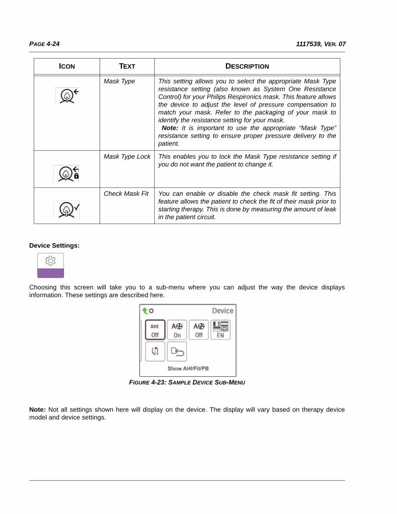
Device Settings:
Choosing this screen will take you to a sub-menu where you can adjust the way the device displaysinformation. These settings are described here.
FIGURE 4-23: SAMPLE DEVICE SUB-MENU
Note: Not all settings shown here will display on the device. The display will vary based on therapy devicemodel and device settings.
Mask Type This setting allows you to select the appropriate Mask Typeresistance setting (also known as System One ResistanceControl) for your Philips Respironics mask. This feature allowsthe device to adjust the level of pressure compensation tomatch your mask. Refer to the packaging of your mask toidentify the resistance setting for your mask. Note: It is important to use the appropriate “Mask Type”resistance setting to ensure proper pressure delivery to thepatient.
Mask Type Lock This enables you to lock the Mask Type resistance setting ifyou do not want the patient to change it.
Check Mask Fit You can enable or disable the check mask fit setting. Thisfeature allows the patient to check the fit of their mask prior tostarting therapy. This is done by measuring the amount of leakin the patient circuit.
ICON TEXT DESCRIPTION
PAGE 4-251117539, VER. 07
ICON TEXT DESCRIPTION
AHI Show AHI/Fit/PB
You can select whether or not the Apnea/Hypopnea index,Mask Fit averages, and Periodic Breathing averages aredisplayed on the Patient Info screens.
cmH2O Pressure Units If enabled on the device, you will have the option to choosethe units of pressure that are displayed. You can choosebetween “cm H2O” or “hPa”.
Automatic On You can enable or disable this feature if you want the deviceto automatically turn the airflow on whenever the patientapplies the interface (mask) to their airway.
Automatic Off You can enable or disable this feature if you want the deviceto automatically turn the airflow off whenever the patientremoves the interface (mask) from their airway.
Language This feature allows you to choose which language to displayon the interface. You can choose English or Spanish.
Clear DefaultReminders
This setting turns off the default patient reminders that areenabled in the therapy device from the factory. Note: This does not turn off additional reminders that youmay have activated in Encore. Encore messages must becleared or modified in Encore.
Reset Data Use the Reset Data function to clear patient data from thetherapy device, as well as an SD card and modem (ifinstalled). After you click to execute Reset Data, the devicewill display a message asking you to confirm the reset. Clickagain to reset data in the device. Note: Reset Data resets Blower Hours that are visible to thepatient, but it does not reset Machine Hours in the ProviderMenu.
PAGE 4-26 1117539, VER. 07
Info Screens:
Choosing this screen will take you to a sub-menu where you can view information on patient usage. These infoscreens are described here.
Note: Not all the screens shown here will display on the device. The display will vary based on therapy devicemodel and device settings.
ICON TEXT DESCRIPTION
Phone In This screen displays the total therapy hours for the device, thetotal blower hours, and the total number of days used when thesessions were greater than 4 hours since the device was lastreset. This screen also displays a compliance check numberyou can use to validate that the data provided to you is the datataken from this screen.
Compliance This screen displays the start day and the total number of daysused when the sessions were greater than 4 hours. Thisscreen also displays a check code number you can use tovalidate that the data provided to you is the data taken from thisscreen.
VIC90 VIC90 This Visual Inspection Check screen will display a check codenumber created from information gathered over the mostrecent 90 day period. This 15 digit number will display as:xxx.xxxx.xxxx.xxxx.
Days>4 Days GreaterThan 4
This screen displays the cumulative number of device therapysessions that exceeded 4 hours over a 1 day, a 7 day, and a 30day time frame.
Therapy Hours The device is capable of recognizing the difference betweenthe time the patient is actually receiving therapy and the timewhen the blower is simply running. This screen displays theamount of time the patient is actually receiving therapy on thedevice for the most recent 1 day time frame. It also displays theaverage amount of time the patient is actually receiving therapyon the device over a 7 day and a 30 day timeframe (provided the device has at least 7 or 30 days of datarespectively). If the device has only 5 days of data to use forthe calculation, the 5 day average value will be seen under the7 day display.
Device Hours This screen displays the number of hours that the blower hasbeen active over the life of the device.
PAGE 4-271117539, VER. 07
Mask Fit Displays the value “100 - % Large Leak”. % Large Leak is thepercentage of time that the mask leak was so high that it is nolonger possible for the device to identify respiratory events withstatistical accuracy. Displays the value for the most recent 1day, as well as the values over last 7 days and 30 days.
AHI AHI The device accumulates individual Apnea/Hypopnea indices(AHI) for each session the patient used the device. This screendisplays the nightly AHI value for the most recent 1 day timeframe. It also displays the average of these individual nightlyAHI values over a 7 day and a 30 day time frame (provided thedevice has at least 7 or 30 days of data respectively). If thedevice has only 5 days of data to use for the calculation, the 5day average value will be seen under the 7 day display.
CSR PeriodicBreathing
During any given night, the device recognizes the percentageof time the patient was experiencing periodic breathing. Thisscreen displays the nightly value of periodic breathing for themost recent 1 day time frame. It also displays the average ofthese individual nightly values of periodic breathing over a 7day and a 30 day time frame (provided the device has at least 7or 30 days of data respectively). If the device has only 5 days ofdata to use for the calculation, the 5 day average value will beseen under the 7 day display.
90% 90% Pressure During any given night, the device recognizes the 90%Pressure achieved by the Auto Algorithm. 90% Pressure isdefined as the pressure at which the device spent 90% of thesession time at or below. For example, if the device recognizedairflow for 10 hours, and 9 hours were spent at or below 11 cmH2O, and 1 hour was spent above 11 cm H2O, then the 90%Pressure would be 11 cm H2O. This screen displays the nightlyvalue of 90% Pressure for the most recent 1 day time frame. Italso displays the average of these individual nightly values of90% Pressure over a 7 day and a 30 day time frame (providedthe device has at least 7 or 30 days of data respectively). If thedevice has only 5 days of data to use for the calculation, the 5day average value will be seen under the 7 day display. Thisscreen only displays if the device is in Auto- CPAP or Auto-Trialtherapy mode.
IPAP 90% IPAP: 90% Pressure
Displays the value of 90% inhalation pressure for the mostrecent 1 day, as well as the average values over the last 7 daysand 30 days. Available on the Auto BiPAP model.
EPAP 90% EPAP: 90% Pressure
Displays the value of 90% exhalation pressure for the mostrecent 1 day, as well as the average values over the last 7 daysand 30 days. Available on the Auto BiPAP model.
A-Trial A-Trial If Auto-Trial mode is available and enabled, this screendisplays Days: xx/xx (where xx/xx is the number of completedtrial days / number of selected trial days).
ICON TEXT DESCRIPTION
PAGE 4-28 1117539, VER. 07
Return to Patient Mode:
Choosing this screen will exit Provider mode and the device will return to the Patient mode. Provider mode willalso time out after 5 minutes of inactivity and automatically return to the Patient mode.
4.11 PERFORMANCE CHECK DEVICE SCREENING TOOL
Performance Check troubleshooting tool is a self-diagnostic utility built into the therapy device. It allows you toquickly evaluate a therapy device remotely. If a patient calls indicating that their therapy does not seem to beoperating properly, just direct them to click on Performance Check in the patient’s My Provider menu. Thecheck operates the blower and screens the device for any operation errors. The screen then displays whetherthe device passed the check (displays a green check mark) or should be returned for service (displays a redX). If a modem is installed, Performance Check will automatically upload a troubleshooting dashboard to theEncore Anywhere patient management software. This dashboard gives you an overview of key device settingsand statistics to help make troubleshooting over the phone easier. If there is not a modem installed in thetherapy device, you can direct the patient to read you the five codes off the Performance Check screen overthe phone. You can decode these codes in EncoreAnywhere, EncorePro or Encore Basic to populate thetroubleshooting dashboard.
4.12 BLUETOOTH WIRELESS TECHNOLOGY
The device may be equipped with Bluetooth wireless technology. If available, you can pair the therapy deviceto a mobile device that has the DreamMapper app installed. DreamMapper is a mobile and web-based systemdesigned to help Obstructive Sleep Apnea (OSA) patients enhance their sleep therapy experience.
4.12.1 PAIRING TO YOUR BLUETOOTH ENABLED MOBILE DEVICE
Follow the steps below to manually pair to your mobile phone or tablet.
1. To pair to your mobile device, first ensure that the Bluetooth setting is turned ON on your mobile device. Refer to your mobile device’s instruction manual for more information.
2. If you need to select from a list of available Bluetooth devices, the therapy device will appear as “PR BT XXXX” (XXXX will be the last four digits of the serial number listed on your therapy device).
3. When your therapy device is powered up but the blower is off, initiate pairing from your mobile device.
4. If your mobile device is in range, one of the following two steps will apply:
NOTES
• You can only pair your therapy device to one mobile device at any giventime.
• Pairing works best when your therapy device and mobile device are in thesame room.
PAGE 4-291117539, VER. 07
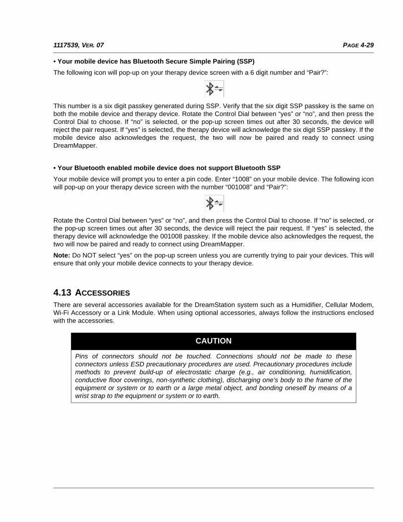
• Your mobile device has Bluetooth Secure Simple Pairing (SSP)
The following icon will pop-up on your therapy device screen with a 6 digit number and “Pair?”:
This number is a six digit passkey generated during SSP. Verify that the six digit SSP passkey is the same onboth the mobile device and therapy device. Rotate the Control Dial between “yes” or “no”, and then press theControl Dial to choose. If “no” is selected, or the pop-up screen times out after 30 seconds, the device willreject the pair request. If “yes” is selected, the therapy device will acknowledge the six digit SSP passkey. If themobile device also acknowledges the request, the two will now be paired and ready to connect usingDreamMapper.
• Your Bluetooth enabled mobile device does not support Bluetooth SSP
Your mobile device will prompt you to enter a pin code. Enter “1008” on your mobile device. The following iconwill pop-up on your therapy device screen with the number “001008” and “Pair?”:
Rotate the Control Dial between “yes” or “no”, and then press the Control Dial to choose. If “no” is selected, orthe pop-up screen times out after 30 seconds, the device will reject the pair request. If “yes” is selected, thetherapy device will acknowledge the 001008 passkey. If the mobile device also acknowledges the request, thetwo will now be paired and ready to connect using DreamMapper.
Note: Do NOT select “yes” on the pop-up screen unless you are currently trying to pair your devices. This willensure that only your mobile device connects to your therapy device.
4.13 ACCESSORIES
There are several accessories available for the DreamStation system such as a Humidifier, Cellular Modem,Wi-Fi Accessory or a Link Module. When using optional accessories, always follow the instructions enclosedwith the accessories.
CAUTION
Pins of connectors should not be touched. Connections should not be made to theseconnectors unless ESD precautionary procedures are used. Precautionary procedures includemethods to prevent build-up of electrostatic charge (e.g., air conditioning, humidification,conductive floor coverings, non-synthetic clothing), discharging one’s body to the frame of theequipment or system or to earth or a large metal object, and bonding oneself by means of awrist strap to the equipment or system or to earth.
PAGE 4-30 1117539, VER. 07
4.13.1 HUMIDIFIER WITH OR WITHOUT HEATED TUBING
You can use the heated humidifier and the heated tube with the device. A humidifier may reduce nasal drynessand irritation by adding moisture to the airflow.
4.13.2 SD CARD
The DreamStation system comes with an SD card inserted in the SD card slot on the side of the device torecord information for the home care provider.
4.13.3 LINK MODULE
The Link Module is able to receive oximetry data and transfer it to the therapy device for home use or in alaboratory setting. For use in Service or in a laboratory setting, the Link Module also includes an RS-232 (or“DB9”) port to allow remote control of the DreamStation Sleep Therapy Device by a personal computer.
To clean the module, remove the module from the therapy device. Wipe the outside of the device with a clothslightly dampened with water and a mild detergent. Let the device dry completely before reinstalling into thetherapy device.
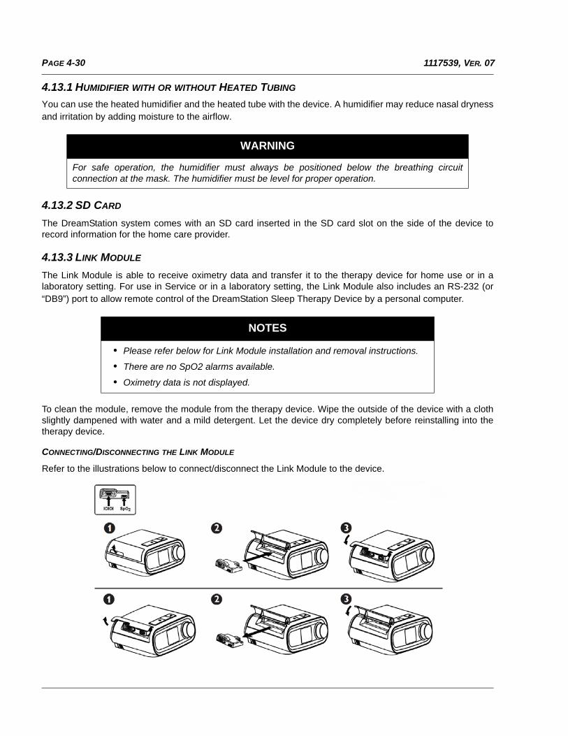
CONNECTING/DISCONNECTING THE LINK MODULE
Refer to the illustrations below to connect/disconnect the Link Module to the device.
WARNING
For safe operation, the humidifier must always be positioned below the breathing circuitconnection at the mask. The humidifier must be level for proper operation.
NOTES
• Please refer below for Link Module installation and removal instructions.
• There are no SpO2 alarms available.
• Oximetry data is not displayed.
PAGE 5-11117539, VER. 07
CHAPTER 5: TROUBLESHOOTING AND ERROR CODES
5.0 INTRODUCTION
This section provides an overview of device troubleshooting, along with corrective actions to take based on theoutcome. You will also find bench checkout procedures, along with tables that include error codes anddescriptions. In addition, you will find troubleshooting guidance based on issues unrelated to error codes.
5.1 BENCH CHECKOUT
5.1.1 PAP DEVICE:
If the PAP device was returned with a Humidifier, perform these steps with and without the Humidifier ifnecessary.
1. Visually inspect the outside of the device for physical damage and broken/missing parts.
2. Verify all components are aligned/seated properly, and not damaged.
3. Apply power to the device and verify the buttons are functioning properly and are properly back-lit, and the LCD is working.
4. If the device was returned with a power cord and power supply, verify that they function properly with/without the device.
5. Turn on the device and verify proper operation of the unit.
6. Verify the device pressure by using a manometer (refer to section 5.2).
7. Listen to the device for noisy operation or loose components.
8. Refer to section 5.2 to retrieve the device Error Log, and refer to the chart for troubleshooting guid-ance based on the Error.
9. Check all other components for physical damage.
10. Perform repairs to the device as necessary.
5.1.2 HUMIDIFIER:
If the Humidifier was returned with a PAP device, perform these steps with the returned PAP device.
1. Visually inspect the outside of the device for physical damage and broken/missing parts.
2. Verify all seals and all other components are aligned/seated properly, and not damaged.
3. Connect the Humidifier to the PAP device and apply power.
4. If the device was returned with a power cord and power supply, verify that they function properly with/without the device.
5. Turn on the PAP device and adjust heater plate setting using the UI Knob to any setting but 0, and let the device run for at least 15 seconds.
6. If a Heated Tube was returned, connect the Tube to the Humidifier, adjust the Heated Tube setting using the UI Knob to any setting but 0, and verify the Tube is warming.
7. Verify the pressure at the Humidifier ISO Port by using a manometer.
8. Verify that the heater plate is heating.
9. Check all other components for physical damage.
10. Perform any repairs as necessary.
PAGE 5-2 1117539, VER. 07
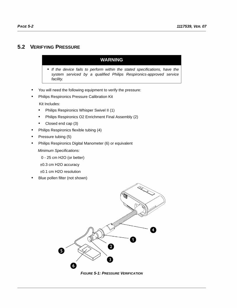
5.2 VERIFYING PRESSURE
• You will need the following equipment to verify the pressure:
• Philips Respironics Pressure Calibration Kit
Kit Includes:
• Philips Respironics Whisper Swivel II (1)
• Philips Respironics O2 Enrichment Final Assembly (2)
• Closed end cap (3)
• Philips Respironics flexible tubing (4)
• Pressure tubing (5)
• Philips Respironics Digital Manometer (6) or equivalent
Minimum Specifications:
0 - 25 cm H2O (or better)
±0.3 cm H2O accuracy
±0.1 cm H2O resolution
• Blue pollen filter (not shown)
FIGURE 5-1: PRESSURE VERIFICATION
WARNING
• If the device fails to perform within the stated specifications, have thesystem serviced by a qualified Philips Respironics-approved servicefacility.
PAGE 5-31117539, VER. 07
To verify the pressure, complete the following steps:
1. Install the blue pollen filter into the device.
2. With the device unplugged, connect the system as illustrated in the diagram.
3. Turn the manometer on. If it does not display a reading of zero, adjust the manometer to calibrate it. If the manometer has variable settings for devices, set it to cm H2O.
4. Supply power to the device then place the device in provider mode.
5. Set the therapy parameters according to the patient specific data.
6. Set the device to the specific pressure value for the patient.
7. Verify that the pressure setting matches the pressure displayed on the manometer. If the pressure setting does not match the measured value for the device, contact Philips Respironics or an autho-rized service center to have the device serviced.
8. Set up the remaining parameters and exit provider mode. The unit is ready for patient use.
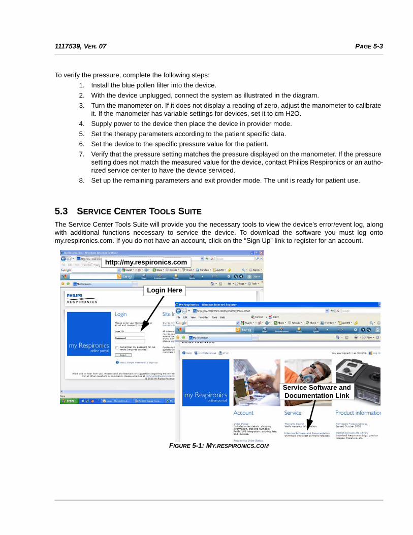
5.3 SERVICE CENTER TOOLS SUITE
The Service Center Tools Suite will provide you the necessary tools to view the device’s error/event log, alongwith additional functions necessary to service the device. To download the software you must log ontomy.respironics.com. If you do not have an account, click on the “Sign Up” link to register for an account.
FIGURE 5-1: MY.RESPIRONICS.COM
Login Here
http://my.respironics.com
Service Software and Documentation Link
PAGE 5-4 1117539, VER. 07
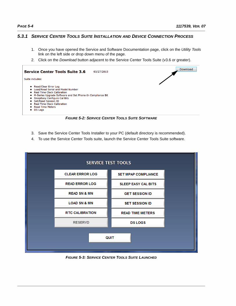
5.3.1 SERVICE CENTER TOOLS SUITE INSTALLATION AND DEVICE CONNECTION PROCESS
1. Once you have opened the Service and Software Documentation page, click on the Utility Tools link on the left side or drop down menu of the page.
2. Click on the Download button adjacent to the Service Center Tools Suite (v3.6 or greater).
FIGURE 5-2: SERVICE CENTER TOOLS SUITE SOFTWARE
3. Save the Service Center Tools Installer to your PC (default directory is recommended).
4. To use the Service Center Tools suite, launch the Service Center Tools Suite software.
FIGURE 5-3: SERVICE CENTER TOOLS SUITE LAUNCHED
PAGE 5-51117539, VER. 07
5. Connect power to the device.
6. Connect the Link Module (PN 1120293) between the Device and PC COM port 1 using the DB-9 Serial Cable. Refer to section 4.13.3 on connecting the Link Module to the device.
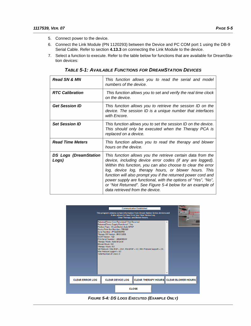
7. Select a function to execute. Refer to the table below for functions that are available for DreamSta-tion devices:
FIGURE 5-4: DS LOGS EXECUTED (EXAMPLE ONLY)
TABLE 5-1: AVAILABLE FUNCTIONS FOR DREAMSTATION DEVICES
Read SN & MN This function allows you to read the serial and modelnumbers of the device.
RTC Calibration This function allows you to set and verify the real time clockon the device.
Get Session ID This function allows you to retrieve the session ID on thedevice. The session ID is a unique number that interfaceswith Encore.
Set Session ID This function allows you to set the session ID on the device.This should only be executed when the Therapy PCA isreplaced on a device.
Read Time Meters This function allows you to read the therapy and blowerhours on the device.
DS Logs (DreamStationLogs)
This function allows you the retrieve certain data from thedevice, including device error codes (if any are logged).Within this function, you can also choose to clear the errorlog, device log, therapy hours, or blower hours. Thisfunction will also prompt you if the returned power cord andpower supply are functional, with the options of “Yes”, “No”,or “Not Returned”. See Figure 5-4 below for an example ofdata retrieved from the device.
PAGE 5-6 1117539, VER. 07
5.3.2 CLEARING THE ERROR AND DEVICE LOGS
• There should be no errors on the device after repairs are made. If there are any errors logged on the device that do not affect device functionality, the error(s) must be cleared. Refer to section 5.3 for a list of error codes, descriptions and corrective actions.
• The device log cannot be read, however the device log should be cleared on the device as part of routine servicing.
5.3.3 CLEARING THERAPY HOURS AND BLOWER HOURS
• If the PCA is NOT replaced during device servicing, the therapy hours should only be cleared if the device is going to a different patient. Otherwise, the therapy hours should remain on the device.
• If the PCA is NOT replaced during device servicing, the blower hours should be cleared only if the Blower is replaced. Otherwise, the blower hours should remain on the device.
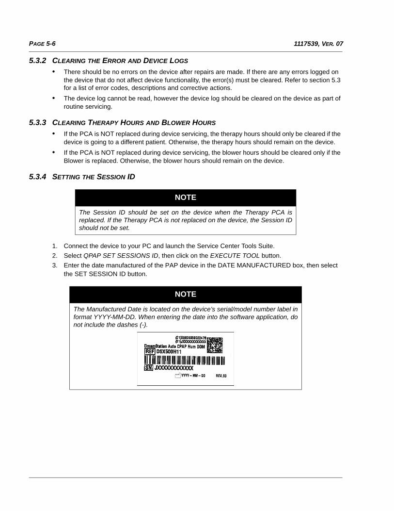
5.3.4 SETTING THE SESSION ID
1. Connect the device to your PC and launch the Service Center Tools Suite.
2. Select QPAP SET SESSIONS ID, then click on the EXECUTE TOOL button.
3. Enter the date manufactured of the PAP device in the DATE MANUFACTURED box, then select the SET SESSION ID button.
NOTE
The Session ID should be set on the device when the Therapy PCA isreplaced. If the Therapy PCA is not replaced on the device, the Session IDshould not be set.
NOTE
The Manufactured Date is located on the device’s serial/model number label informat YYYY-MM-DD. When entering the date into the software application, donot include the dashes (-).
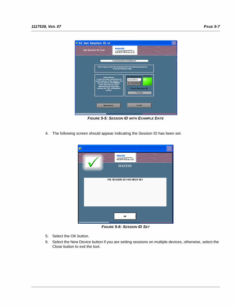
PAGE 5-71117539, VER. 07
FIGURE 5-5: SESSION ID WITH EXAMPLE DATE
4. The following screen should appear indicating the Session ID has been set.
FIGURE 5-6: SESSION ID SET
5. Select the OK button.
6. Select the New Device button if you are setting sessions on multiple devices, otherwise, select the Close button to exit the tool.
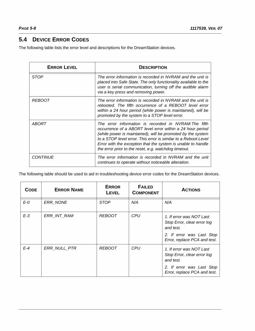
PAGE 5-8 1117539, VER. 07
5.4 DEVICE ERROR CODES
The following table lists the error level and descriptions for the DreamStation devices.
The following table should be used to aid in troubleshooting device error codes for the DreamStation devices.
ERROR LEVEL DESCRIPTION
STOP The error information is recorded in NVRAM and the unit isplaced into Safe State. The only functionality available to theuser is serial communication, turning off the audible alarmvia a key press and removing power.
REBOOT The error information is recorded in NVRAM and the unit isrebooted. The fifth occurrence of a REBOOT level errorwithin a 24 hour period (while power is maintained), will bepromoted by the system to a STOP level error.
ABORT The error information is recorded in NVRAM.The fifthoccurrence of a ABORT level error within a 24 hour period(while power is maintained), will be promoted by the systemto a STOP level error. This error is similar to a Reboot-LevelError with the exception that the system is unable to handlethe error prior to the reset, e.g. watchdog timeout.
CONTINUE The error information is recorded in NVRAM and the unitcontinues to operate without noticeable alteration.
CODE ERROR NAMEERROR LEVEL
FAILED COMPONENT
ACTIONS
E-0 ERR_NONE STOP N/A N/A
E-3 ERR_INT_RAM REBOOT CPU 1. If error was NOT Last Stop Error, clear error log and test.
2. If error was Last StopError, replace PCA and test.
E-4 ERR_NULL_PTR REBOOT CPU 1. If error was NOT Last Stop Error, clear error log and test.
2. If error was Last StopError, replace PCA and test.
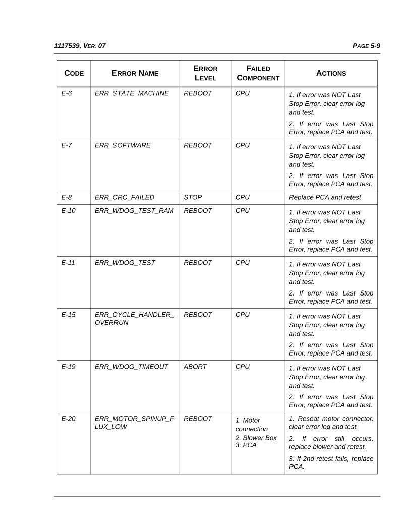
PAGE 5-91117539, VER. 07
E-6 ERR_STATE_MACHINE REBOOT CPU 1. If error was NOT Last Stop Error, clear error log and test.
2. If error was Last StopError, replace PCA and test.
E-7 ERR_SOFTWARE REBOOT CPU 1. If error was NOT Last Stop Error, clear error log and test.
2. If error was Last StopError, replace PCA and test.
E-8 ERR_CRC_FAILED STOP CPU Replace PCA and retest
E-10 ERR_WDOG_TEST_RAM REBOOT CPU 1. If error was NOT Last Stop Error, clear error log and test.
2. If error was Last StopError, replace PCA and test.
E-11 ERR_WDOG_TEST REBOOT CPU 1. If error was NOT Last Stop Error, clear error log and test.
2. If error was Last StopError, replace PCA and test.
E-15 ERR_CYCLE_HANDLER_OVERRUN
REBOOT CPU 1. If error was NOT Last Stop Error, clear error log and test.
2. If error was Last StopError, replace PCA and test.
E-19 ERR_WDOG_TIMEOUT ABORT CPU 1. If error was NOT Last Stop Error, clear error log and test.
2. If error was Last StopError, replace PCA and test.
E-20 ERR_MOTOR_SPINUP_FLUX_LOW
REBOOT 1. Motor connection2. Blower Box3. PCA
1. Reseat motor connector,clear error log and test.
2. If error still occurs,replace blower and retest.
3. If 2nd retest fails, replacePCA.
CODE ERROR NAMEERROR LEVEL
FAILED COMPONENT
ACTIONS
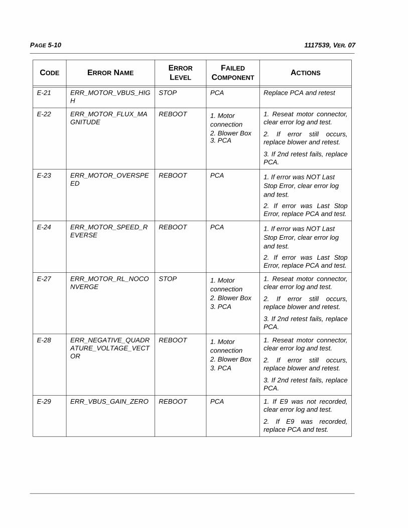
PAGE 5-10 1117539, VER. 07
E-21 ERR_MOTOR_VBUS_HIGH
STOP PCA Replace PCA and retest
E-22 ERR_MOTOR_FLUX_MAGNITUDE
REBOOT 1. Motor connection2. Blower Box3. PCA
1. Reseat motor connector,clear error log and test.
2. If error still occurs,replace blower and retest.
3. If 2nd retest fails, replacePCA.
E-23 ERR_MOTOR_OVERSPEED
REBOOT PCA 1. If error was NOT Last Stop Error, clear error log and test.
2. If error was Last StopError, replace PCA and test.
E-24 ERR_MOTOR_SPEED_REVERSE
REBOOT PCA 1. If error was NOT Last Stop Error, clear error log and test.
2. If error was Last StopError, replace PCA and test.
E-27 ERR_MOTOR_RL_NOCONVERGE
STOP 1. Motor connection2. Blower Box3. PCA
1. Reseat motor connector,clear error log and test.
2. If error still occurs,replace blower and retest.
3. If 2nd retest fails, replacePCA.
E-28 ERR_NEGATIVE_QUADRATURE_VOLTAGE_VECTOR
REBOOT 1. Motor connection2. Blower Box3. PCA
1. Reseat motor connector,clear error log and test.
2. If error still occurs,replace blower and retest.
3. If 2nd retest fails, replacePCA.
E-29 ERR_VBUS_GAIN_ZERO REBOOT PCA 1. If E9 was not recorded,clear error log and test.
2. If E9 was recorded,replace PCA and test.
CODE ERROR NAMEERROR LEVEL
FAILED COMPONENT
ACTIONS
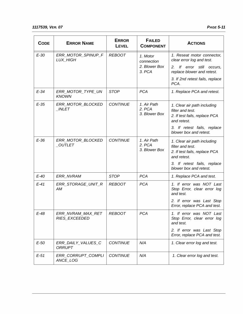
PAGE 5-111117539, VER. 07
E-30 ERR_MOTOR_SPINUP_FLUX_HIGH
REBOOT 1. Motor connection2. Blower Box3. PCA
1. Reseat motor connector,clear error log and test.
2. If error still occurs,replace blower and retest.
3. If 2nd retest fails, replacePCA.
E-34 ERR_MOTOR_TYPE_UNKNOWN
STOP PCA 1. Replace PCA and retest.
E-35 ERR_MOTOR_BLOCKED_INLET
CONTINUE 1. Air Path2. PCA3. Blower Box
1. Clear air path including filter and test.2. If test fails, replace PCA and retest.
3. If retest fails, replaceblower box and retest.
E-36 ERR_MOTOR_BLOCKED_OUTLET
CONTINUE 1. Air Path2. PCA3. Blower Box
1. Clear air path including filter and test.2. If test fails, replace PCA and retest.
3. If retest fails, replaceblower box and retest.
E-40 ERR_NVRAM STOP PCA 1. Replace PCA and test.
E-41 ERR_STORAGE_UNIT_RAM
REBOOT PCA 1. If error was NOT LastStop Error, clear error logand test.
2. If error was Last StopError, replace PCA and test.
E-48 ERR_NVRAM_MAX_RETRIES_EXCEEDED
REBOOT PCA 1. If error was NOT LastStop Error, clear error logand test.
2. If error was Last StopError, replace PCA and test.
E-50 ERR_DAILY_VALUES_CORRUPT
CONTINUE N/A 1. Clear error log and test.
E-51 ERR_CORRUPT_COMPLIANCE_LOG
CONTINUE N/A 1. Clear error log and test.
CODE ERROR NAMEERROR LEVEL
FAILED COMPONENT
ACTIONS
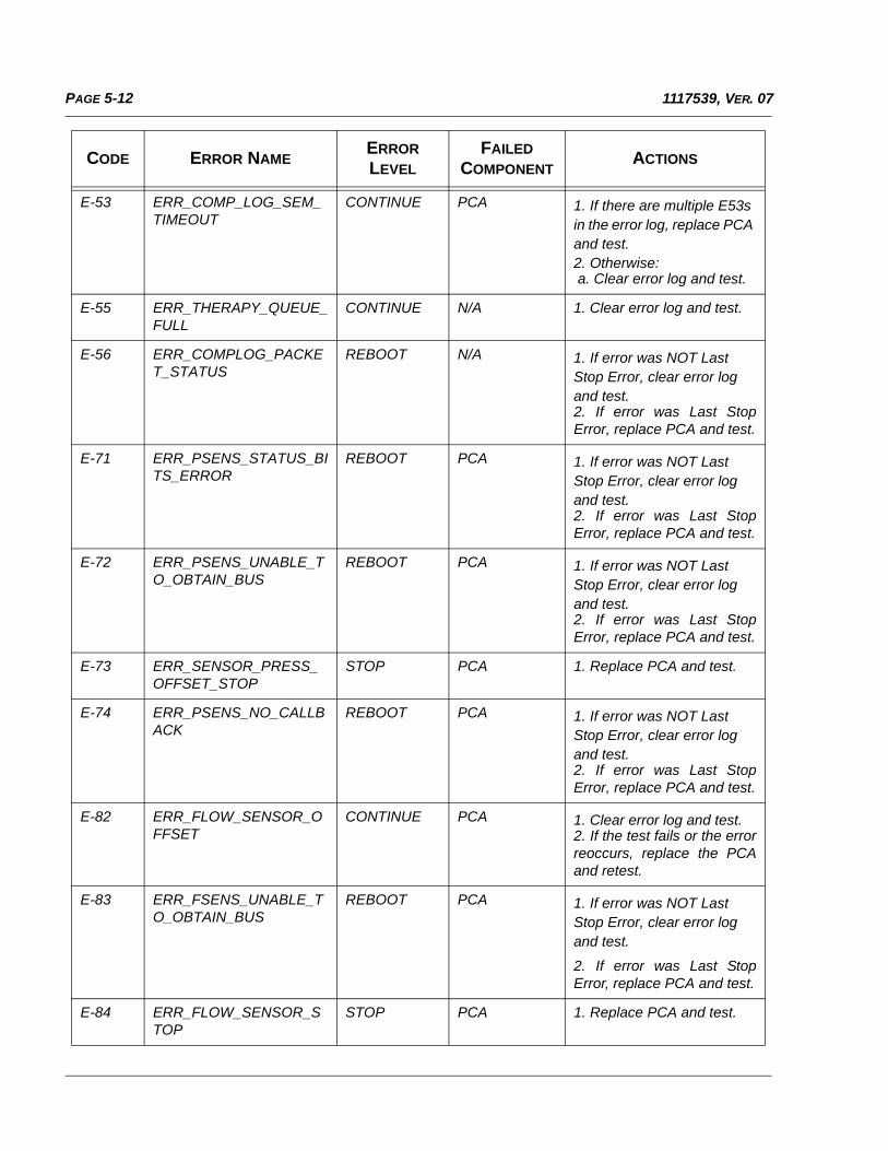
PAGE 5-12 1117539, VER. 07
E-53 ERR_COMP_LOG_SEM_TIMEOUT
CONTINUE PCA 1. If there are multiple E53s in the error log, replace PCA and test.2. Otherwise: a. Clear error log and test.
E-55 ERR_THERAPY_QUEUE_FULL
CONTINUE N/A 1. Clear error log and test.
E-56 ERR_COMPLOG_PACKET_STATUS
REBOOT N/A 1. If error was NOT Last Stop Error, clear error log and test.2. If error was Last StopError, replace PCA and test.
E-71 ERR_PSENS_STATUS_BITS_ERROR
REBOOT PCA 1. If error was NOT Last Stop Error, clear error log and test.2. If error was Last StopError, replace PCA and test.
E-72 ERR_PSENS_UNABLE_TO_OBTAIN_BUS
REBOOT PCA 1. If error was NOT Last Stop Error, clear error log and test.2. If error was Last StopError, replace PCA and test.
E-73 ERR_SENSOR_PRESS_OFFSET_STOP
STOP PCA 1. Replace PCA and test.
E-74 ERR_PSENS_NO_CALLBACK
REBOOT PCA 1. If error was NOT Last Stop Error, clear error log and test.2. If error was Last StopError, replace PCA and test.
E-82 ERR_FLOW_SENSOR_OFFSET
CONTINUE PCA 1. Clear error log and test.2. If the test fails or the errorreoccurs, replace the PCAand retest.
E-83 ERR_FSENS_UNABLE_TO_OBTAIN_BUS
REBOOT PCA 1. If error was NOT Last Stop Error, clear error log and test.
2. If error was Last StopError, replace PCA and test.
E-84 ERR_FLOW_SENSOR_STOP
STOP PCA 1. Replace PCA and test.
CODE ERROR NAMEERROR LEVEL
FAILED COMPONENT
ACTIONS
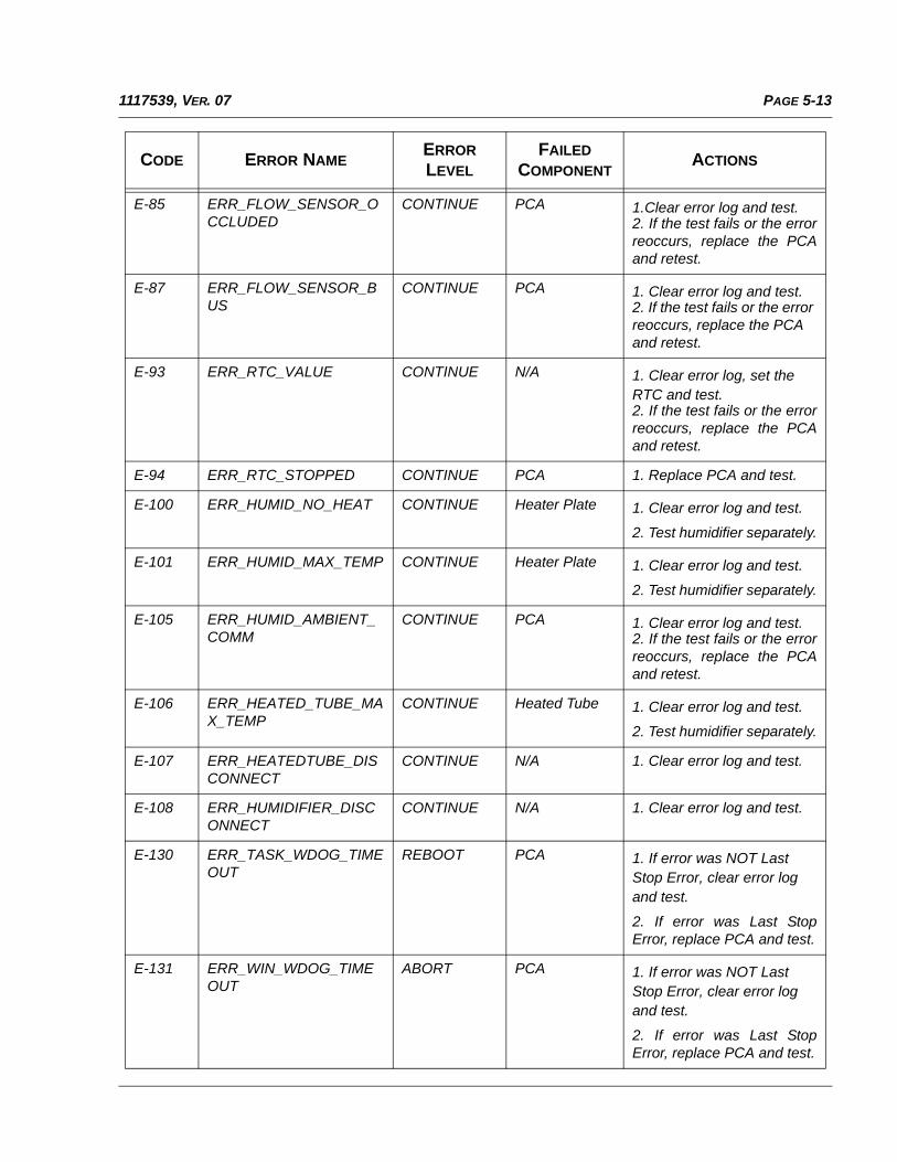
PAGE 5-131117539, VER. 07
E-85 ERR_FLOW_SENSOR_OCCLUDED
CONTINUE PCA 1.Clear error log and test.2. If the test fails or the errorreoccurs, replace the PCAand retest.
E-87 ERR_FLOW_SENSOR_BUS
CONTINUE PCA 1. Clear error log and test.2. If the test fails or the error reoccurs, replace the PCA and retest.
E-93 ERR_RTC_VALUE CONTINUE N/A 1. Clear error log, set the RTC and test.2. If the test fails or the errorreoccurs, replace the PCAand retest.
E-94 ERR_RTC_STOPPED CONTINUE PCA 1. Replace PCA and test.
E-100 ERR_HUMID_NO_HEAT CONTINUE Heater Plate 1. Clear error log and test.
2. Test humidifier separately.
E-101 ERR_HUMID_MAX_TEMP CONTINUE Heater Plate 1. Clear error log and test.
2. Test humidifier separately.
E-105 ERR_HUMID_AMBIENT_COMM
CONTINUE PCA 1. Clear error log and test.2. If the test fails or the errorreoccurs, replace the PCAand retest.
E-106 ERR_HEATED_TUBE_MAX_TEMP
CONTINUE Heated Tube 1. Clear error log and test.
2. Test humidifier separately.
E-107 ERR_HEATEDTUBE_DISCONNECT
CONTINUE N/A 1. Clear error log and test.
E-108 ERR_HUMIDIFIER_DISCONNECT
CONTINUE N/A 1. Clear error log and test.
E-130 ERR_TASK_WDOG_TIMEOUT
REBOOT PCA 1. If error was NOT Last Stop Error, clear error log and test.
2. If error was Last StopError, replace PCA and test.
E-131 ERR_WIN_WDOG_TIMEOUT
ABORT PCA 1. If error was NOT Last Stop Error, clear error log and test.
2. If error was Last StopError, replace PCA and test.
CODE ERROR NAMEERROR LEVEL
FAILED COMPONENT
ACTIONS
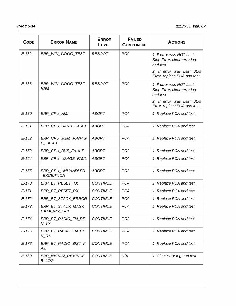
PAGE 5-14 1117539, VER. 07
E-132 ERR_WIN_WDOG_TEST REBOOT PCA 1. If error was NOT Last Stop Error, clear error log and test.
2. If error was Last StopError, replace PCA and test.
E-133 ERR_WIN_WDOG_TEST_RAM
REBOOT PCA 1. If error was NOT Last Stop Error, clear error log and test.
2. If error was Last StopError, replace PCA and test.
E-150 ERR_CPU_NMI ABORT PCA 1. Replace PCA and test.
E-151 ERR_CPU_HARD_FAULT ABORT PCA 1. Replace PCA and test.
E-152 ERR_CPU_MEM_MANAGE_FAULT
ABORT PCA 1. Replace PCA and test.
E-153 ERR_CPU_BUS_FAULT ABORT PCA 1. Replace PCA and test.
E-154 ERR_CPU_USAGE_FAULT
ABORT PCA 1. Replace PCA and test.
E-155 ERR_CPU_UNHANDLED_EXCEPTION
ABORT PCA 1. Replace PCA and test.
E-170 ERR_BT_RESET_TX CONTINUE PCA 1. Replace PCA and test.
E-171 ERR_BT_RESET_RX CONTINUE PCA 1. Replace PCA and test.
E-172 ERR_BT_STACK_ERROR CONTINUE PCA 1. Replace PCA and test.
E-173 ERR_BT_STACK_MASK_DATA_WR_FAIL
CONTINUE PCA 1. Replace PCA and test.
E-174 ERR_BT_RADIO_EN_DEN_TX
CONTINUE PCA 1. Replace PCA and test.
E-175 ERR_BT_RADIO_EN_DEN_RX
CONTINUE PCA 1. Replace PCA and test.
E-176 ERR_BT_RADIO_BIST_FAIL
CONTINUE PCA 1. Replace PCA and test.
E-180 ERR_NVRAM_REMINDER_LOG
CONTINUE N/A 1. Clear error log and test.
CODE ERROR NAMEERROR LEVEL
FAILED COMPONENT
ACTIONS
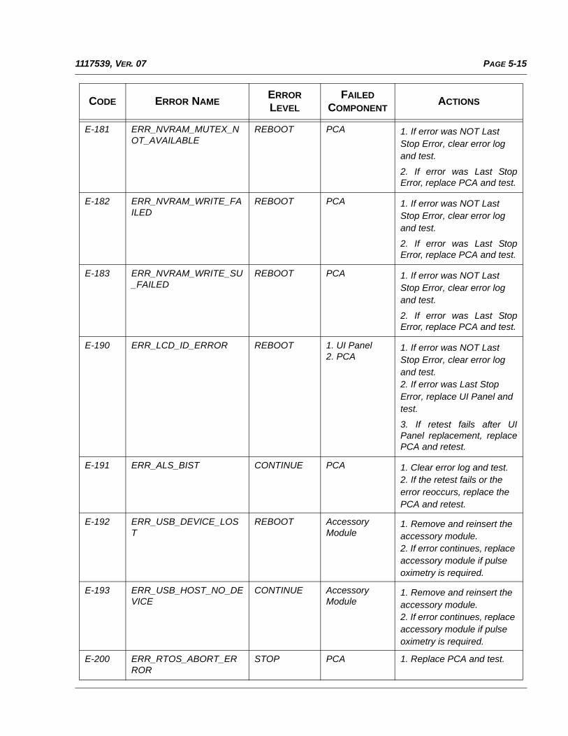
PAGE 5-151117539, VER. 07
E-181 ERR_NVRAM_MUTEX_NOT_AVAILABLE
REBOOT PCA 1. If error was NOT Last Stop Error, clear error log and test.
2. If error was Last StopError, replace PCA and test.
E-182 ERR_NVRAM_WRITE_FAILED
REBOOT PCA 1. If error was NOT Last Stop Error, clear error log and test.
2. If error was Last StopError, replace PCA and test.
E-183 ERR_NVRAM_WRITE_SU_FAILED
REBOOT PCA 1. If error was NOT Last Stop Error, clear error log and test.
2. If error was Last StopError, replace PCA and test.
E-190 ERR_LCD_ID_ERROR REBOOT 1. UI Panel2. PCA
1. If error was NOT Last Stop Error, clear error log and test.2. If error was Last Stop Error, replace UI Panel and test.
3. If retest fails after UIPanel replacement, replacePCA and retest.
E-191 ERR_ALS_BIST CONTINUE PCA 1. Clear error log and test.2. If the retest fails or the error reoccurs, replace the PCA and retest.
E-192 ERR_USB_DEVICE_LOST
REBOOT AccessoryModule
1. Remove and reinsert the accessory module.2. If error continues, replace accessory module if pulse oximetry is required.
E-193 ERR_USB_HOST_NO_DEVICE
CONTINUE AccessoryModule
1. Remove and reinsert the accessory module.2. If error continues, replace accessory module if pulse oximetry is required.
E-200 ERR_RTOS_ABORT_ERROR
STOP PCA 1. Replace PCA and test.
CODE ERROR NAMEERROR LEVEL
FAILED COMPONENT
ACTIONS
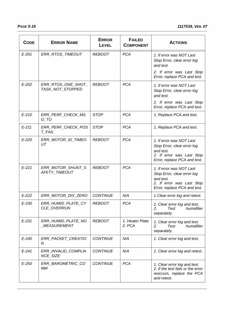
PAGE 5-16 1117539, VER. 07
E-201 ERR_RTOS_TIMEOUT REBOOT PCA 1. If error was NOT Last Stop Error, clear error log and test.
2. If error was Last StopError, replace PCA and test.
E-202 ERR_RTOS_ONE_SHOT_TASK_NOT_STOPPED
REBOOT PCA 1. If error was NOT Last Stop Error, clear error log and test.
2. If error was Last StopError, replace PCA and test.
E-210 ERR_PERF_CHECK_MSG_TO
STOP PCA 1. Replace PCA and test.
E-211 ERR_PERF_CHECK_POST_FAIL
STOP PCA 1. Replace PCA and test.
E-220 ERR_MOTOR_ID_TIMEOUT
REBOOT PCA 1. If error was NOT Last Stop Error, clear error log and test.2. If error was Last StopError, replace PCA and test.
E-221 ERR_MOTOR_SHUNT_SAFETY_TIMEOUT
REBOOT PCA 1. If error was NOT Last Stop Error, clear error log and test.2. If error was Last StopError, replace PCA and test.
E-222 ERR_MOTOR_DIV_ZERO CONTINUE N/A 1 Clear error log and retest.
E-230 ERR_HUMID_PLATE_CYCLE_OVERRUN
REBOOT PCA 1. Clear error log and test.2. Test humidifierseparately.
E-231 ERR_HUMID_PLATE_NO_MEASUREMENT
REBOOT 1. Heater Plate2. PCA
1. Clear error log and test.2. Test humidifierseparately.
E-240 ERR_PACKET_CREATION
CONTINUE N/A 1. Clear error log and test.
E-241 ERR_INVALID_COMPLIANCE_SIZE
CONTINUE N/A 1. Clear error log and retest.
E-250 ERR_BAROMETRIC_COMM
CONTINUE PCA 1. Clear error log and test.2. If the test fails or the errorreoccurs, replace the PCAand retest.
CODE ERROR NAMEERROR LEVEL
FAILED COMPONENT
ACTIONS
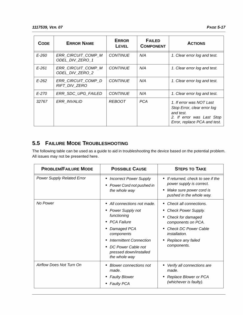
PAGE 5-171117539, VER. 07
5.5 FAILURE MODE TROUBLESHOOTING
The following table can be used as a guide to aid in troubleshooting the device based on the potential problem.All issues may not be presented here.
E-260 ERR_CIRCUIT_COMP_MODEL_DIV_ZERO_1
CONTINUE N/A 1. Clear error log and test.
E-261 ERR_CIRCUIT_COMP_MODEL_DIV_ZERO_2
CONTINUE N/A 1. Clear error log and test.
E-262 ERR_CIRCUIT_COMP_DRIFT_DIV_ZERO
CONTINUE N/A 1. Clear error log and test.
E-270 ERR_SDC_UPG_FAILED CONTINUE N/A 1. Clear error log and test.
32767 ERR_INVALID REBOOT PCA 1. If error was NOT Last Stop Error, clear error log and test.2. If error was Last StopError, replace PCA and test.
PROBLEM/FAILURE MODE POSSIBLE CAUSE STEPS TO TAKE
Power Supply Related Error • Incorrect Power Supply
• Power Cord not pushed in the whole way
• If returned, check to see if the power supply is correct.
• Make sure power cord is pushed in the whole way.
No Power • All connections not made.
• Power Supply not functioning
• PCA Failure
• Damaged PCA components
• Intermittent Connection
• DC Power Cable not pressed down/installed the whole way
• Check all connections.
• Check Power Supply.
• Check for damaged components on PCA.
• Check DC Power Cable installation.
• Replace any failed components.
Airflow Does Not Turn On • Blower connections not made.
• Faulty Blower
• Faulty PCA
• Verify all connections are made.
• Replace Blower or PCA (whichever is faulty).
CODE ERROR NAMEERROR LEVEL
FAILED COMPONENT
ACTIONS
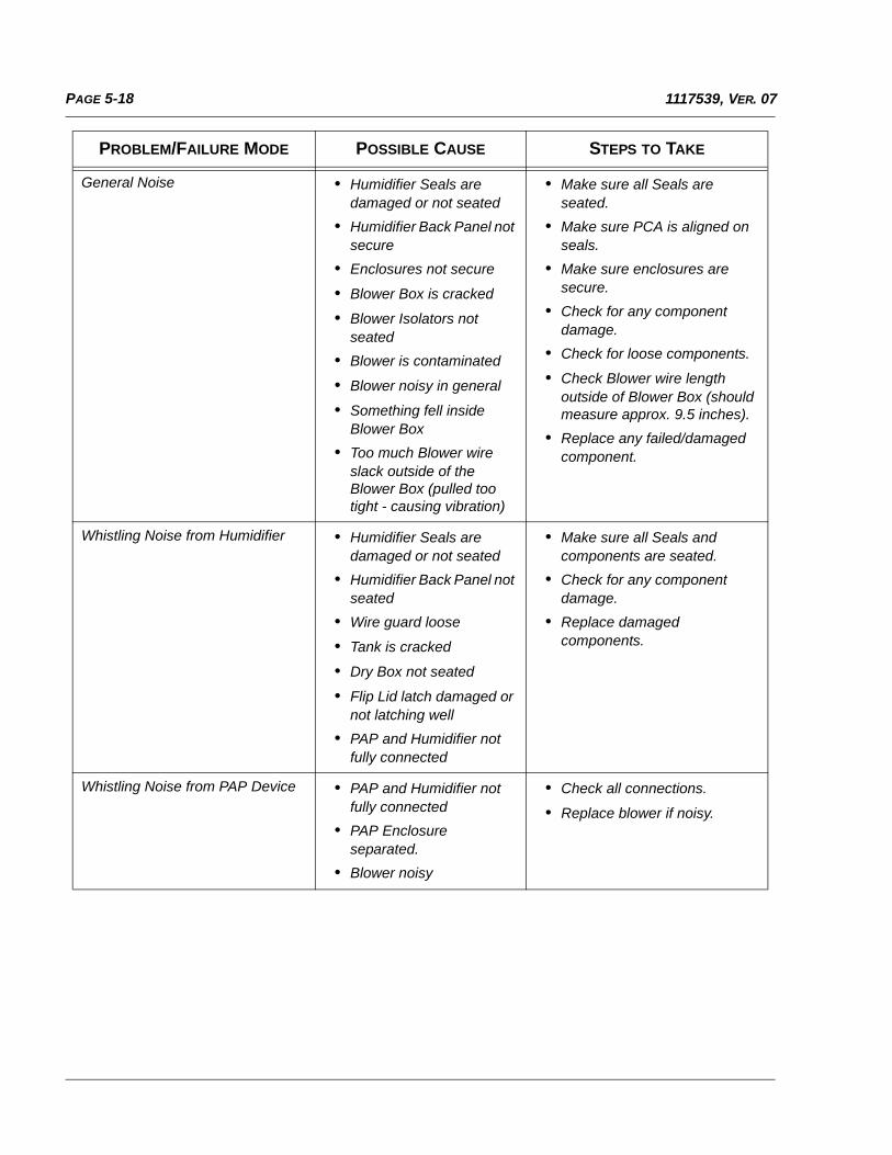
PAGE 5-18 1117539, VER. 07
General Noise • Humidifier Seals are damaged or not seated
• Humidifier Back Panel not secure
• Enclosures not secure
• Blower Box is cracked
• Blower Isolators not seated
• Blower is contaminated
• Blower noisy in general
• Something fell inside Blower Box
• Too much Blower wire slack outside of the Blower Box (pulled too tight - causing vibration)
• Make sure all Seals are seated.
• Make sure PCA is aligned on seals.
• Make sure enclosures are secure.
• Check for any component damage.
• Check for loose components.
• Check Blower wire length outside of Blower Box (should measure approx. 9.5 inches).
• Replace any failed/damaged component.
Whistling Noise from Humidifier • Humidifier Seals are damaged or not seated
• Humidifier Back Panel not seated
• Wire guard loose
• Tank is cracked
• Dry Box not seated
• Flip Lid latch damaged or not latching well
• PAP and Humidifier not fully connected
• Make sure all Seals and components are seated.
• Check for any component damage.
• Replace damaged components.
Whistling Noise from PAP Device • PAP and Humidifier not fully connected
• PAP Enclosure separated.
• Blower noisy
• Check all connections.
• Replace blower if noisy.
PROBLEM/FAILURE MODE POSSIBLE CAUSE STEPS TO TAKE
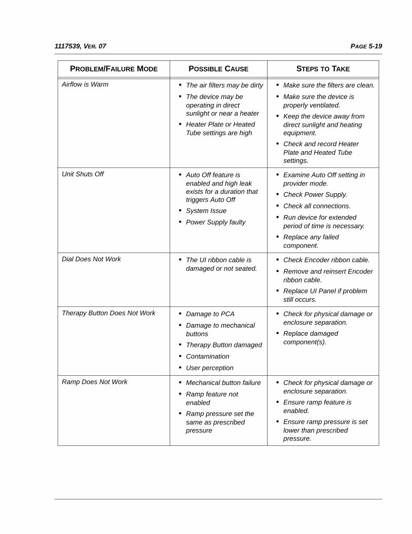
PAGE 5-191117539, VER. 07
Airflow is Warm • The air filters may be dirty
• The device may be operating in direct sunlight or near a heater
• Heater Plate or Heated Tube settings are high
• Make sure the filters are clean.
• Make sure the device is properly ventilated.
• Keep the device away from direct sunlight and heating equipment.
• Check and record Heater Plate and Heated Tube settings.
Unit Shuts Off • Auto Off feature is enabled and high leak exists for a duration that triggers Auto Off
• System Issue
• Power Supply faulty
• Examine Auto Off setting in provider mode.
• Check Power Supply.
• Check all connections.
• Run device for extended period of time is necessary.
• Replace any failed component.
Dial Does Not Work • The UI ribbon cable is damaged or not seated.
• Check Encoder ribbon cable.
• Remove and reinsert Encoder ribbon cable.
• Replace UI Panel if problem still occurs.
Therapy Button Does Not Work • Damage to PCA
• Damage to mechanical buttons
• Therapy Button damaged
• Contamination
• User perception
• Check for physical damage or enclosure separation.
• Replace damaged component(s).
Ramp Does Not Work • Mechanical button failure
• Ramp feature not enabled
• Ramp pressure set the same as prescribed pressure
• Check for physical damage or enclosure separation.
• Ensure ramp feature is enabled.
• Ensure ramp pressure is set lower than prescribed pressure.
PROBLEM/FAILURE MODE POSSIBLE CAUSE STEPS TO TAKE
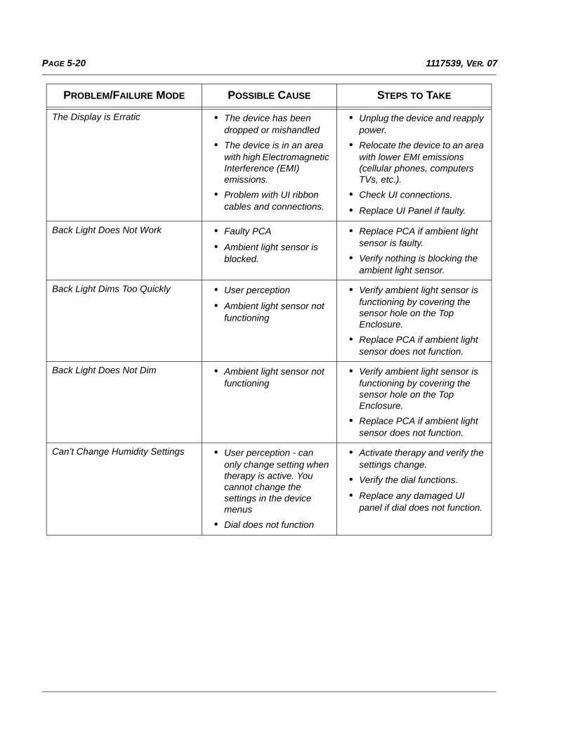
PAGE 5-20 1117539, VER. 07
The Display is Erratic • The device has been dropped or mishandled
• The device is in an area with high Electromagnetic Interference (EMI) emissions.
• Problem with UI ribbon cables and connections.
• Unplug the device and reapply power.
• Relocate the device to an area with lower EMI emissions (cellular phones, computers TVs, etc.).
• Check UI connections.
• Replace UI Panel if faulty.
Back Light Does Not Work • Faulty PCA
• Ambient light sensor is blocked.
• Replace PCA if ambient light sensor is faulty.
• Verify nothing is blocking the ambient light sensor.
Back Light Dims Too Quickly • User perception
• Ambient light sensor not functioning
• Verify ambient light sensor is functioning by covering the sensor hole on the Top Enclosure.
• Replace PCA if ambient light sensor does not function.
Back Light Does Not Dim • Ambient light sensor not functioning
• Verify ambient light sensor is functioning by covering the sensor hole on the Top Enclosure.
• Replace PCA if ambient light sensor does not function.
Can’t Change Humidity Settings • User perception - can only change setting when therapy is active. You cannot change the settings in the device menus
• Dial does not function
• Activate therapy and verify the settings change.
• Verify the dial functions.
• Replace any damaged UI panel if dial does not function.
PROBLEM/FAILURE MODE POSSIBLE CAUSE STEPS TO TAKE
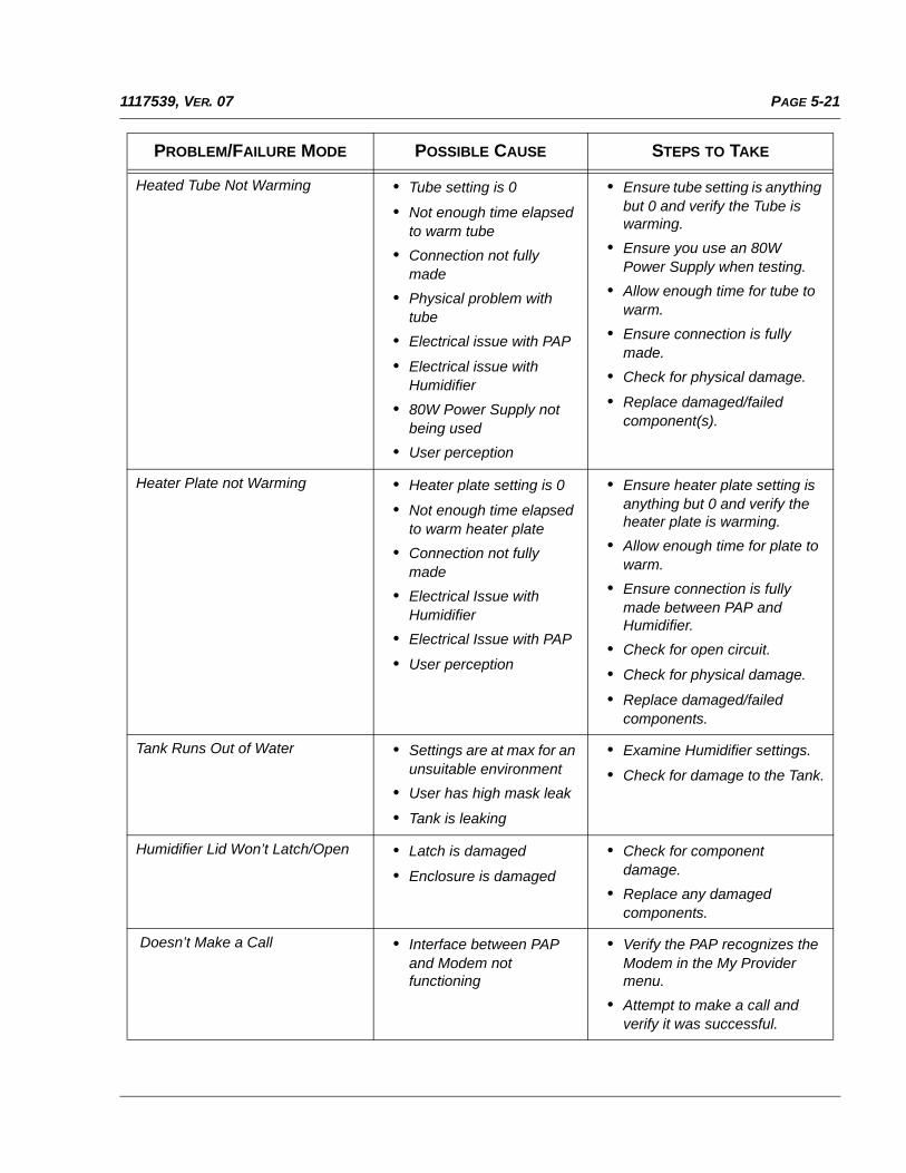
PAGE 5-211117539, VER. 07
Heated Tube Not Warming • Tube setting is 0
• Not enough time elapsed to warm tube
• Connection not fully made
• Physical problem with tube
• Electrical issue with PAP
• Electrical issue with Humidifier
• 80W Power Supply not being used
• User perception
• Ensure tube setting is anything but 0 and verify the Tube is warming.
• Ensure you use an 80W Power Supply when testing.
• Allow enough time for tube to warm.
• Ensure connection is fully made.
• Check for physical damage.
• Replace damaged/failed component(s).
Heater Plate not Warming • Heater plate setting is 0
• Not enough time elapsed to warm heater plate
• Connection not fully made
• Electrical Issue with Humidifier
• Electrical Issue with PAP
• User perception
• Ensure heater plate setting is anything but 0 and verify the heater plate is warming.
• Allow enough time for plate to warm.
• Ensure connection is fully made between PAP and Humidifier.
• Check for open circuit.
• Check for physical damage.
• Replace damaged/failed components.
Tank Runs Out of Water • Settings are at max for an unsuitable environment
• User has high mask leak
• Tank is leaking
• Examine Humidifier settings.
• Check for damage to the Tank.
Humidifier Lid Won’t Latch/Open • Latch is damaged
• Enclosure is damaged
• Check for component damage.
• Replace any damaged components.
Doesn’t Make a Call • Interface between PAP and Modem not functioning
• Verify the PAP recognizes the Modem in the My Provider menu.
• Attempt to make a call and verify it was successful.
PROBLEM/FAILURE MODE POSSIBLE CAUSE STEPS TO TAKE
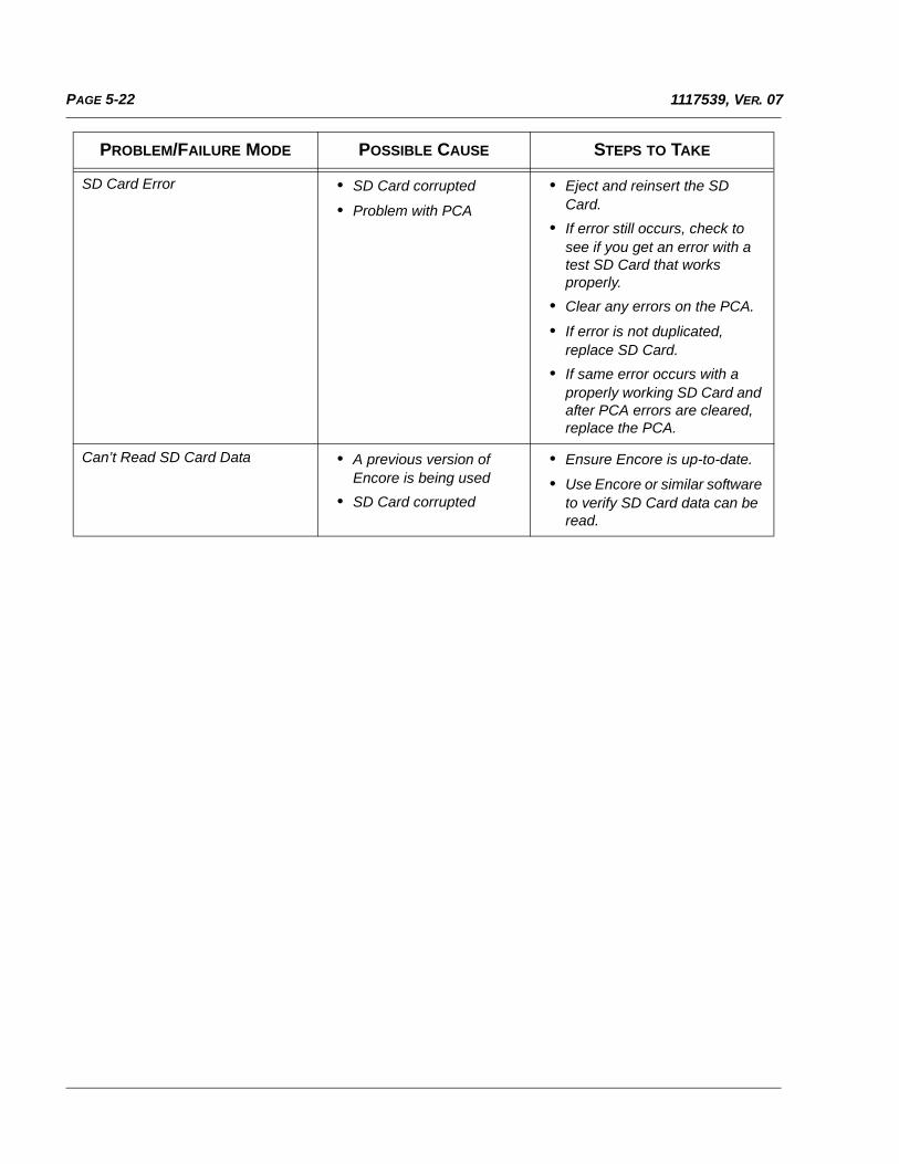
PAGE 5-22 1117539, VER. 07
SD Card Error • SD Card corrupted
• Problem with PCA
• Eject and reinsert the SD Card.
• If error still occurs, check to see if you get an error with a test SD Card that works properly.
• Clear any errors on the PCA.
• If error is not duplicated, replace SD Card.
• If same error occurs with a properly working SD Card and after PCA errors are cleared, replace the PCA.
Can’t Read SD Card Data • A previous version of Encore is being used
• SD Card corrupted
• Ensure Encore is up-to-date.
• Use Encore or similar software to verify SD Card data can be read.
PROBLEM/FAILURE MODE POSSIBLE CAUSE STEPS TO TAKE
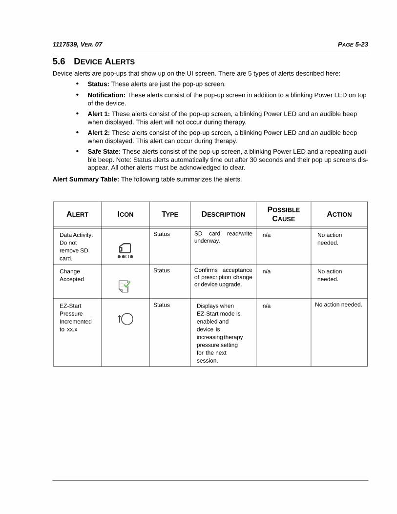
PAGE 5-231117539, VER. 07
5.6 DEVICE ALERTS
Device alerts are pop-ups that show up on the UI screen. There are 5 types of alerts described here:
• Status: These alerts are just the pop-up screen.
• Notification: These alerts consist of the pop-up screen in addition to a blinking Power LED on top of the device.
• Alert 1: These alerts consist of the pop-up screen, a blinking Power LED and an audible beep when displayed. This alert will not occur during therapy.
• Alert 2: These alerts consist of the pop-up screen, a blinking Power LED and an audible beep when displayed. This alert can occur during therapy.
• Safe State: These alerts consist of the pop-up screen, a blinking Power LED and a repeating audi-ble beep. Note: Status alerts automatically time out after 30 seconds and their pop up screens dis-appear. All other alerts must be acknowledged to clear.
Alert Summary Table: The following table summarizes the alerts.
ALERT ICON TYPE DESCRIPTIONPOSSIBLE
CAUSEACTION
Data Activity: Do not remove SD card.
Status SD card read/writeunderway.
n/a No action needed.
Change Accepted
Status Confirms acceptanceof prescription changeor device upgrade.
n/a No action needed.
EZ-Start Pressure Incremented to xx.x
Status Displays whenEZ-Start mode is enabled and device is increasing therapy pressure setting for the next session.
n/a No action needed.
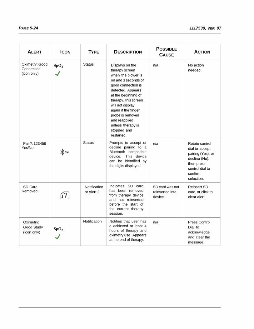
PAGE 5-24 1117539, VER. 07
Oximetry: GoodConnection(icon only)
SpO2Status Displays on the
therapy screen when the blower is on and 3 seconds of good connection is detected. Appears at the beginning of therapy.This screen will not display again if the finger probe is removed and reapplied unless therapy is stopped and restarted.
n/a No action needed.
Pair?: 123456Yes/No
Status Prompts to accept ordecline pairing to aBluetooth compatibledevice. This devicecan be identified bythe digits displayed.
n/a Rotate control dial to accept pairing (Yes), or decline (No), then press control dial to confirm selection.
SD CardRemoved.
Notificationor Alert 2
Indicates SD cardhas been removedfrom therapy deviceand not reinsertedbefore the start ofthe current therapysession.
SD card was not reinserted into device.
Reinsert SD card, or click to clear alert.
Oximetry: Good Study (icon only)
SpO2
Notification Notifies that user hasa achieved at least 4hours of therapy andoximetry use. Appearsat the end of therapy.
n/a Press Control Dial to acknowledge and clear the message.
ALERT ICON TYPE DESCRIPTIONPOSSIBLE
CAUSEACTION
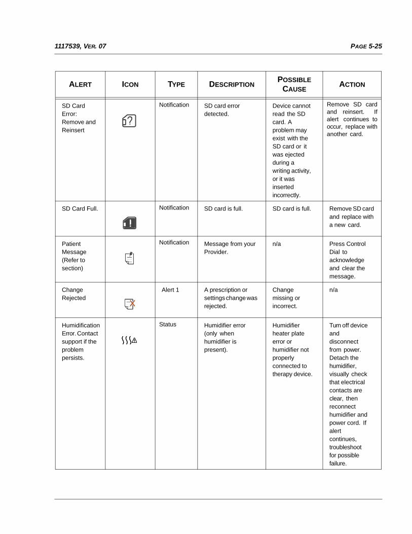
PAGE 5-251117539, VER. 07
SD Card Error: Remove and Reinsert
Notification SD card error detected.
Device cannot read the SD card. A problem may exist with the SD card or it was ejected during a writing activity, or it was inserted incorrectly.
Remove SD cardand reinsert. Ifalert continues tooccur, replace withanother card.
SD Card Full. Notification SD card is full. SD card is full. Remove SD card and replace with a new card.
Patient Message (Refer to section)
Notification Message from your Provider.
n/a Press Control Dial to acknowledge and clear the message.
Change Rejected
Alert 1 A prescription or settings change was rejected.
Change missing or incorrect.
n/a
Humidification Error. Contact support if the problem persists.
Status Humidifier error (only when humidifier is present).
Humidifier heater plate error or humidifier not properly connected to therapy device.
Turn off device and disconnect from power. Detach the humidifier, visually check that electrical contacts are clear, then reconnect humidifier and power cord. If alert continues, troubleshoot for possible failure.
ALERT ICON TYPE DESCRIPTIONPOSSIBLE
CAUSEACTION
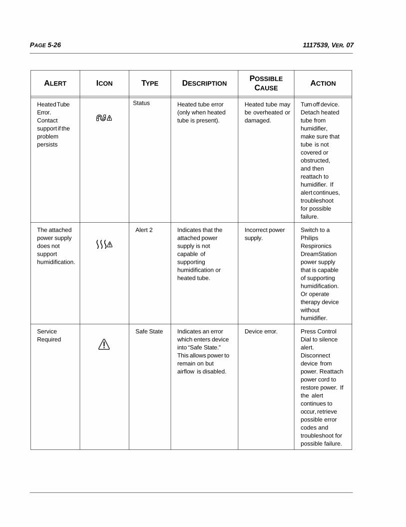
PAGE 5-26 1117539, VER. 07
Heated Tube Error. Contact support if the problem persists
Status Heated tube error (only when heated tube is present).
Heated tube maybe overheated ordamaged.
Turn off device. Detach heated tube from humidifier, make sure that tube is not covered or obstructed, and then reattach to humidifier. If alert continues, troubleshoot for possible failure.
The attached power supply does not support humidification.
Alert 2 Indicates that the attached power supply is not capable of supporting humidification or heated tube.
Incorrect power supply.
Switch to a Philips Respironics DreamStation power supply that is capable of supporting humidification. Or operate therapy device without humidifier.
Service Required
Safe State Indicates an error which enters device into “Safe State.” This allows power to remain on but airflow is disabled.
Device error. Press Control Dial to silence alert. Disconnect device from power. Reattach power cord to restore power. If the alert continues to occur, retrieve possible error codes and troubleshoot for possible failure.
ALERT ICON TYPE DESCRIPTIONPOSSIBLE
CAUSEACTION
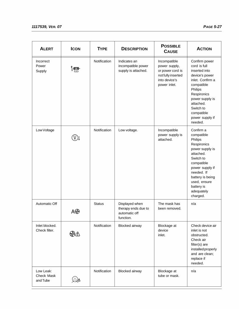
PAGE 5-271117539, VER. 07
Incorrect Power
Supply
Notification Indicates an incompatible power supply is attached.
Incompatible power supply, or power cord is not fully inserted into device’s power inlet.
Confirm power cord is full inserted into device’s power inlet. Confirm a compatible Philips Respironics power supply is attached. Switch to compatible power supply if needed.
Low Voltage Notification Low voltage. Incompatible power supply is attached.
Confirm a compatible Philips Respironics power supply is attached. Switch to compatible power supply if needed. If battery is being used, ensure battery is adequately charged.
Automatic Off Status Displayed when therapy ends due to automatic off function.
The mask has been removed.
n/a
Inlet blocked.Check filter.
Notification Blocked airway Blockage at deviceinlet.
Check device air inlet is not obstructed. Check air filter(s) are installed properly and are clean; replace if needed.
Low Leak: Check Mask and Tube
Notification Blocked airway Blockage at tube or mask.
n/a
ALERT ICON TYPE DESCRIPTIONPOSSIBLE
CAUSEACTION
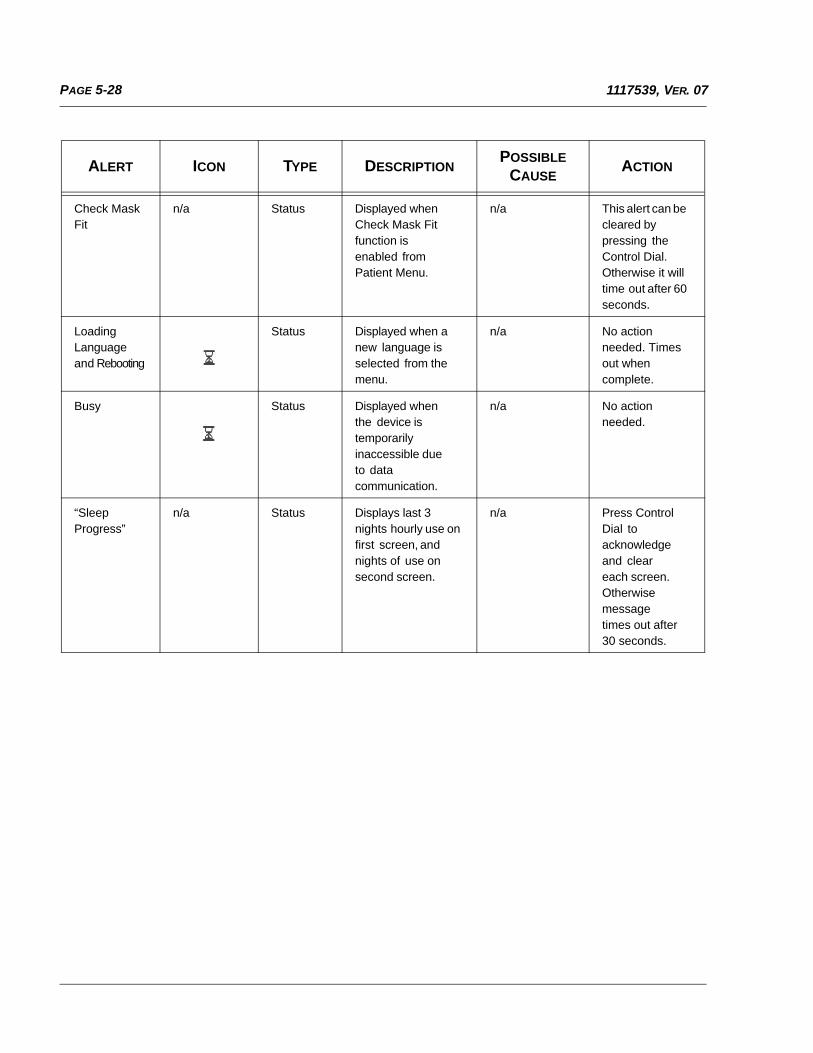
PAGE 5-28 1117539, VER. 07
Check Mask Fit
n/a Status Displayed when Check Mask Fit function is enabled from Patient Menu.
n/a This alert can be cleared by pressing the Control Dial. Otherwise it will time out after 60 seconds.
Loading Language and Rebooting
Status Displayed when a new language is selected from the menu.
n/a No action needed. Times out when complete.
Busy Status Displayed when the device is temporarily inaccessible due to data communication.
n/a No action needed.
“Sleep Progress”
n/a Status Displays last 3 nights hourly use on first screen, and nights of use on second screen.
n/a Press Control Dial to acknowledge and clear each screen. Otherwise message times out after 30 seconds.
ALERT ICON TYPE DESCRIPTIONPOSSIBLE
CAUSEACTION
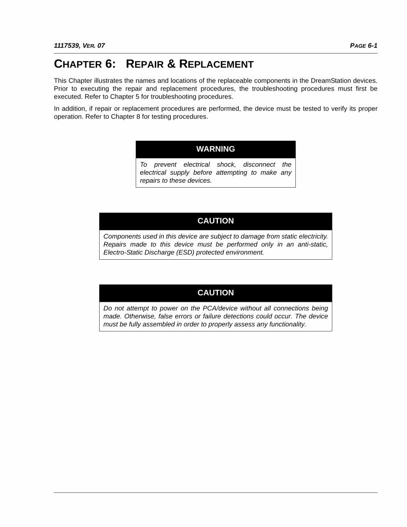
PAGE 6-11117539, VER. 07
CHAPTER 6: REPAIR & REPLACEMENT
This Chapter illustrates the names and locations of the replaceable components in the DreamStation devices.Prior to executing the repair and replacement procedures, the troubleshooting procedures must first beexecuted. Refer to Chapter 5 for troubleshooting procedures.
In addition, if repair or replacement procedures are performed, the device must be tested to verify its properoperation. Refer to Chapter 8 for testing procedures.
WARNING
To prevent electrical shock, disconnect theelectrical supply before attempting to make anyrepairs to these devices.
CAUTION
Components used in this device are subject to damage from static electricity.Repairs made to this device must be performed only in an anti-static,Electro-Static Discharge (ESD) protected environment.
CAUTION
Do not attempt to power on the PCA/device without all connections beingmade. Otherwise, false errors or failure detections could occur. The devicemust be fully assembled in order to properly assess any functionality.

PAGE 6-2 1117539, VER. 07
6.0 REPLACEMENT PART (RP) KITS
DESCRIPTION RP KIT NUMBER
Accessory Module Flip Door 1115485
SD Cover Flip Door 1115542
Upper Enclosure(Includes Keypad)
1115486
UI Panel Assembly 1115538
PCA, CPAP 1121520
PCA, CPAP Pro 1121522
PCA, Auto CPAP 1121523
PCA, BiPAP Pro 1121525
PCA, Auto BiPAP 1121526
Pressure Sensor Seal 1121527
Flow Sensor Seal 1115484
Blower Upper Cap 1115481
Blower Box Assembly 1121548
Blower Assembly, SK 1121550
Blower Isolators, SK 1121552
Blower Assembly, Moog 1121549
Blower Isolators, Moog 1121551
Blower Outlet Seal 1121553
DC Power Cable 1121554
DC Jack Color Insert 1121555
Rear Panel 1115543
Rear Panel O-Ring 1121559
Bottom Enclosure 1115487
Warning Label, DOM 1121556
Warning Label, INTL 1121557
Warning Label, Canada/Latin America 1125963
Warning Label, Japan 1127612
Power Supply, 80W 1118499
Travel Power Supply, DOM, 65W 1120136
Travel Power Supply, EU, 65W 1127194
Travel Power Supply, CN, 65W 1127195
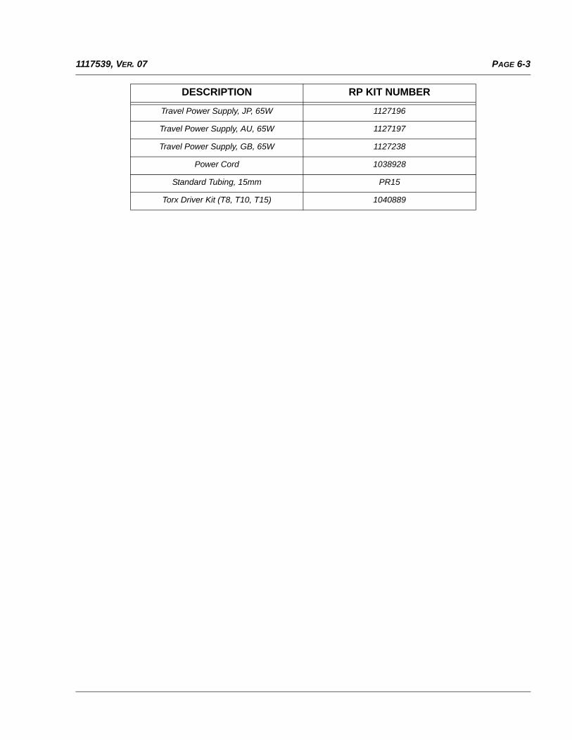
PAGE 6-31117539, VER. 07
Travel Power Supply, JP, 65W 1127196
Travel Power Supply, AU, 65W 1127197
Travel Power Supply, GB, 65W 1127238
Power Cord 1038928
Standard Tubing, 15mm PR15
Torx Driver Kit (T8, T10, T15) 1040889
DESCRIPTION RP KIT NUMBER
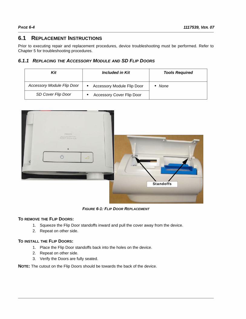
PAGE 6-4 1117539, VER. 07
6.1 REPLACEMENT INSTRUCTIONS
Prior to executing repair and replacement procedures, device troubleshooting must be performed. Refer toChapter 5 for troubleshooting procedures.
6.1.1 REPLACING THE ACCESSORY MODULE AND SD FLIP DOORS
FIGURE 6-1: FLIP DOOR REPLACEMENT
TO REMOVE THE FLIP DOORS:
1. Squeeze the Flip Door standoffs inward and pull the cover away from the device.
2. Repeat on other side.
TO INSTALL THE FLIP DOORS:
1. Place the Flip Door standoffs back into the holes on the device.
2. Repeat on other side.
3. Verify the Doors are fully seated.
NOTE: The cutout on the Flip Doors should be towards the back of the device.
Kit Included in Kit Tools Required
Accessory Module Flip Door • Accessory Module Flip Door • None
SD Cover Flip Door • Accessory Cover Flip Door
Standoffs
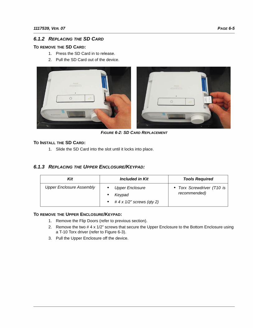
PAGE 6-51117539, VER. 07
6.1.2 REPLACING THE SD CARD
TO REMOVE THE SD CARD:
1. Press the SD Card in to release.
2. Pull the SD Card out of the device.
FIGURE 6-2: SD CARD REPLACEMENT
TO INSTALL THE SD CARD:
1. Slide the SD Card into the slot until it locks into place.
6.1.3 REPLACING THE UPPER ENCLOSURE/KEYPAD:
TO REMOVE THE UPPER ENCLOSURE/KEYPAD:1. Remove the Flip Doors (refer to previous section).
2. Remove the two # 4 x 1/2” screws that secure the Upper Enclosure to the Bottom Enclosure usinga T-10 Torx driver (refer to Figure 6-3).
3. Pull the Upper Enclosure off the device.
Kit Included in Kit Tools Required
Upper Enclosure Assembly • Upper Enclosure
• Keypad
• # 4 x 1/2” screws (qty 2)
• Torx Screwdriver (T10 isrecommended)
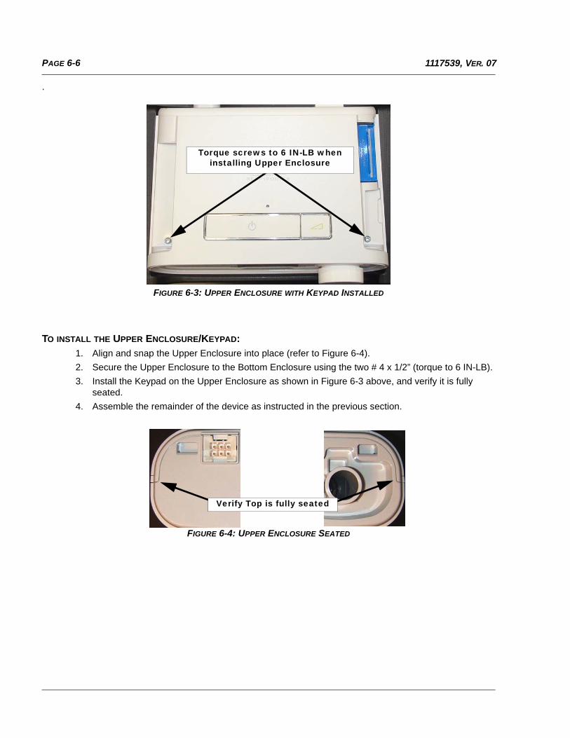
PAGE 6-6 1117539, VER. 07
.
FIGURE 6-3: UPPER ENCLOSURE WITH KEYPAD INSTALLED
TO INSTALL THE UPPER ENCLOSURE/KEYPAD:
1. Align and snap the Upper Enclosure into place (refer to Figure 6-4).
2. Secure the Upper Enclosure to the Bottom Enclosure using the two # 4 x 1/2” (torque to 6 IN-LB).
3. Install the Keypad on the Upper Enclosure as shown in Figure 6-3 above, and verify it is fullyseated.
4. Assemble the remainder of the device as instructed in the previous section.
FIGURE 6-4: UPPER ENCLOSURE SEATED
Torque screws to 6 IN-LB when installing Upper Enclosure
Verify Top is fully seated
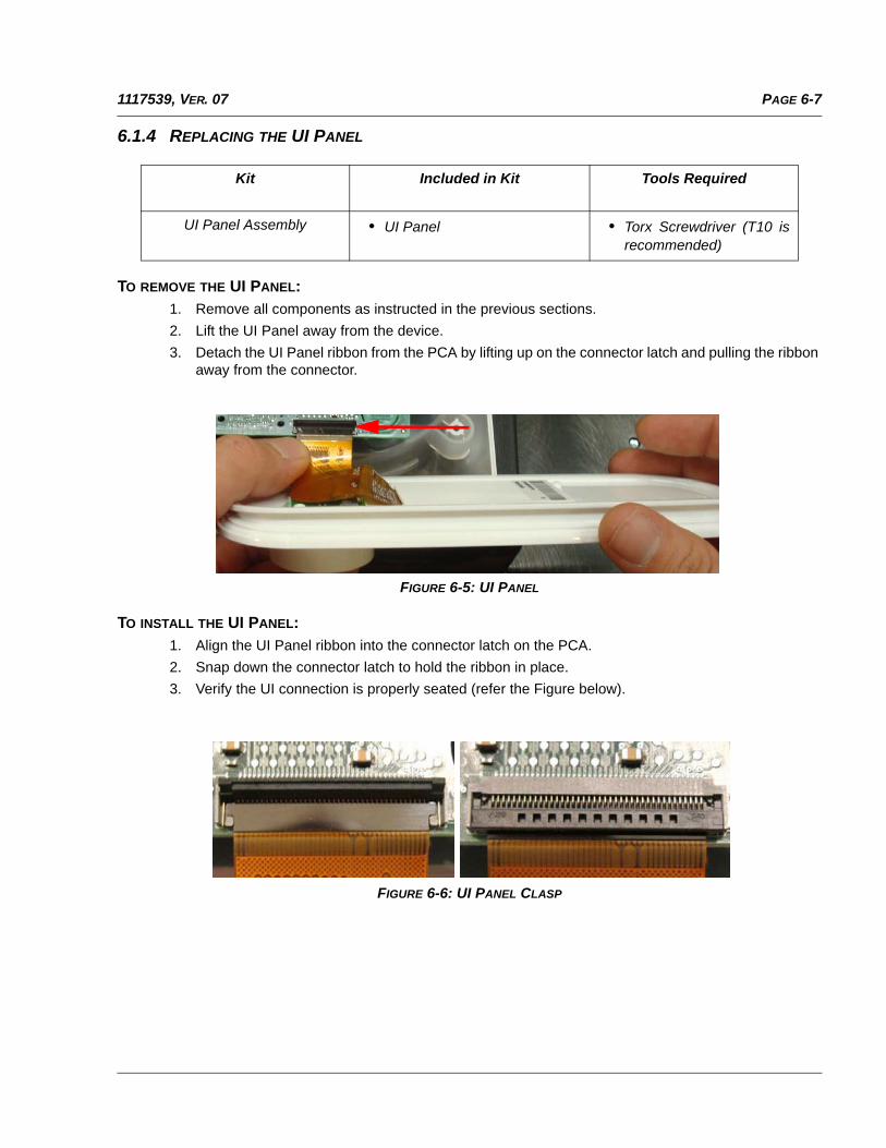
PAGE 6-71117539, VER. 07
6.1.4 REPLACING THE UI PANEL
TO REMOVE THE UI PANEL:
1. Remove all components as instructed in the previous sections.
2. Lift the UI Panel away from the device.
3. Detach the UI Panel ribbon from the PCA by lifting up on the connector latch and pulling the ribbonaway from the connector.
FIGURE 6-5: UI PANEL
TO INSTALL THE UI PANEL:
1. Align the UI Panel ribbon into the connector latch on the PCA.
2. Snap down the connector latch to hold the ribbon in place.
3. Verify the UI connection is properly seated (refer the Figure below).
FIGURE 6-6: UI PANEL CLASP
Kit Included in Kit Tools Required
UI Panel Assembly • UI Panel • Torx Screwdriver (T10 isrecommended)
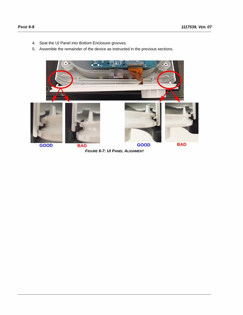
PAGE 6-8 1117539, VER. 07
4. Seat the UI Panel into Bottom Enclosure grooves.
5. Assemble the remainder of the device as instructed in the previous sections.
FIGURE 6-7: UI PANEL ALIGNMENT
GOOD BAD BAD GOOD
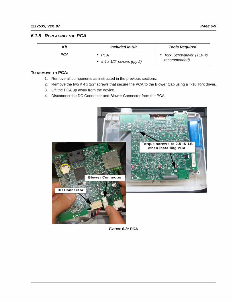
PAGE 6-91117539, VER. 07
6.1.5 REPLACING THE PCA
TO REMOVE TH PCA:1. Remove all components as instructed in the previous sections.
2. Remove the two # 4 x 1/2” screws that secure the PCA to the Blower Cap using a T-10 Torx driver.
3. Lift the PCA up away from the device.
4. Disconnect the DC Connector and Blower Connector from the PCA.
FIGURE 6-8: PCA
Kit Included in Kit Tools Required
PCA • PCA
• # 4 x 1/2” screws (qty 2)
• Torx Screwdriver (T10 isrecommended)
Torque screws to 2.5 IN-LB when installing PCA.
DC Connector
Blower Connector
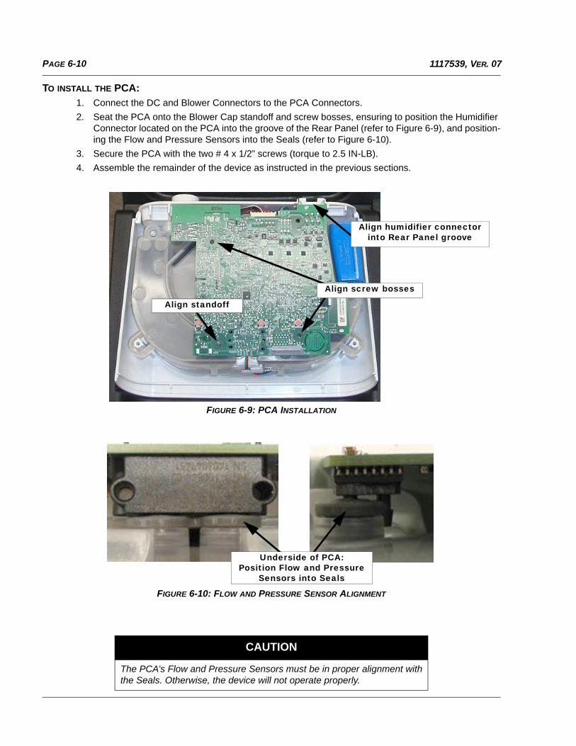
PAGE 6-10 1117539, VER. 07
TO INSTALL THE PCA:
1. Connect the DC and Blower Connectors to the PCA Connectors.
2. Seat the PCA onto the Blower Cap standoff and screw bosses, ensuring to position the Humidifier Connector located on the PCA into the groove of the Rear Panel (refer to Figure 6-9), and position-ing the Flow and Pressure Sensors into the Seals (refer to Figure 6-10).
3. Secure the PCA with the two # 4 x 1/2” screws (torque to 2.5 IN-LB).
4. Assemble the remainder of the device as instructed in the previous sections.
FIGURE 6-9: PCA INSTALLATION
FIGURE 6-10: FLOW AND PRESSURE SENSOR ALIGNMENT
CAUTION
The PCA’s Flow and Pressure Sensors must be in proper alignment withthe Seals. Otherwise, the device will not operate properly.
Align standoff
Align humidifier connector into Rear Panel groove
Align screw bosses
Underside of PCA:Position Flow and Pressure
Sensors into Seals
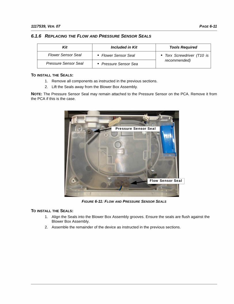
PAGE 6-111117539, VER. 07
6.1.6 REPLACING THE FLOW AND PRESSURE SENSOR SEALS
TO INSTALL THE SEALS:
1. Remove all components as instructed in the previous sections.
2. Lift the Seals away from the Blower Box Assembly.
NOTE: The Pressure Sensor Seal may remain attached to the Pressure Sensor on the PCA. Remove it fromthe PCA if this is the case.
FIGURE 6-11: FLOW AND PRESSURE SENSOR SEALS
TO INSTALL THE SEALS:
1. Align the Seals into the Blower Box Assembly grooves. Ensure the seals are flush against theBlower Box Assembly.
2. Assemble the remainder of the device as instructed in the previous sections.
Kit Included in Kit Tools Required
Flower Sensor Seal • Flower Sensor Seal • Torx Screwdriver (T10 isrecommended)
Pressure Sensor Seal • Pressure Sensor Sea
Pressure Sensor Seal
Flow Sensor Seal
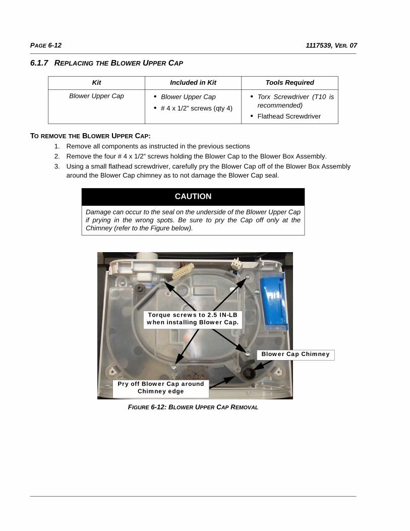
PAGE 6-12 1117539, VER. 07
6.1.7 REPLACING THE BLOWER UPPER CAP
TO REMOVE THE BLOWER UPPER CAP:
1. Remove all components as instructed in the previous sections
2. Remove the four # 4 x 1/2” screws holding the Blower Cap to the Blower Box Assembly.
3. Using a small flathead screwdriver, carefully pry the Blower Cap off of the Blower Box Assembly around the Blower Cap chimney as to not damage the Blower Cap seal.
FIGURE 6-12: BLOWER UPPER CAP REMOVAL
Kit Included in Kit Tools Required
Blower Upper Cap • Blower Upper Cap
• # 4 x 1/2” screws (qty 4)
• Torx Screwdriver (T10 isrecommended)
• Flathead Screwdriver
CAUTION
Damage can occur to the seal on the underside of the Blower Upper Capif prying in the wrong spots. Be sure to pry the Cap off only at theChimney (refer to the Figure below).
Pry off Blower Cap around Chimney edge
Blower Cap Chimney
Torque screws to 2.5 IN-LB when installing Blower Cap.
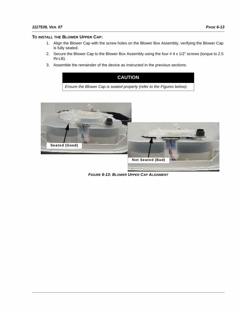
PAGE 6-131117539, VER. 07
TO INSTALL THE BLOWER UPPER CAP:
1. Align the Blower Cap with the screw holes on the Blower Box Assembly, verifying the Blower Capis fully seated.
2. Secure the Blower Cap to the Blower Box Assembly using the four # 4 x 1/2” screws (torque to 2.5IN-LB).
3. Assemble the remainder of the device as instructed in the previous sections.
FIGURE 6-13: BLOWER UPPER CAP ALIGNMENT
CAUTION
Ensure the Blower Cap is seated properly (refer to the Figures below).
Not Seated (Bad)
Seated (Good)
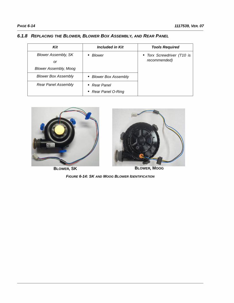
PAGE 6-14 1117539, VER. 07
6.1.8 REPLACING THE BLOWER, BLOWER BOX ASSEMBLY, AND REAR PANEL
FIGURE 6-14: SK AND MOOG BLOWER IDENTIFICATION
Kit Included in Kit Tools Required
Blower Assembly, SK
or
Blower Assembly, Moog
• Blower • Torx Screwdriver (T10 isrecommended)
Blower Box Assembly • Blower Box Assembly
Rear Panel Assembly • Rear Panel
• Rear Panel O-Ring
BLOWER, SK BLOWER, MOOG
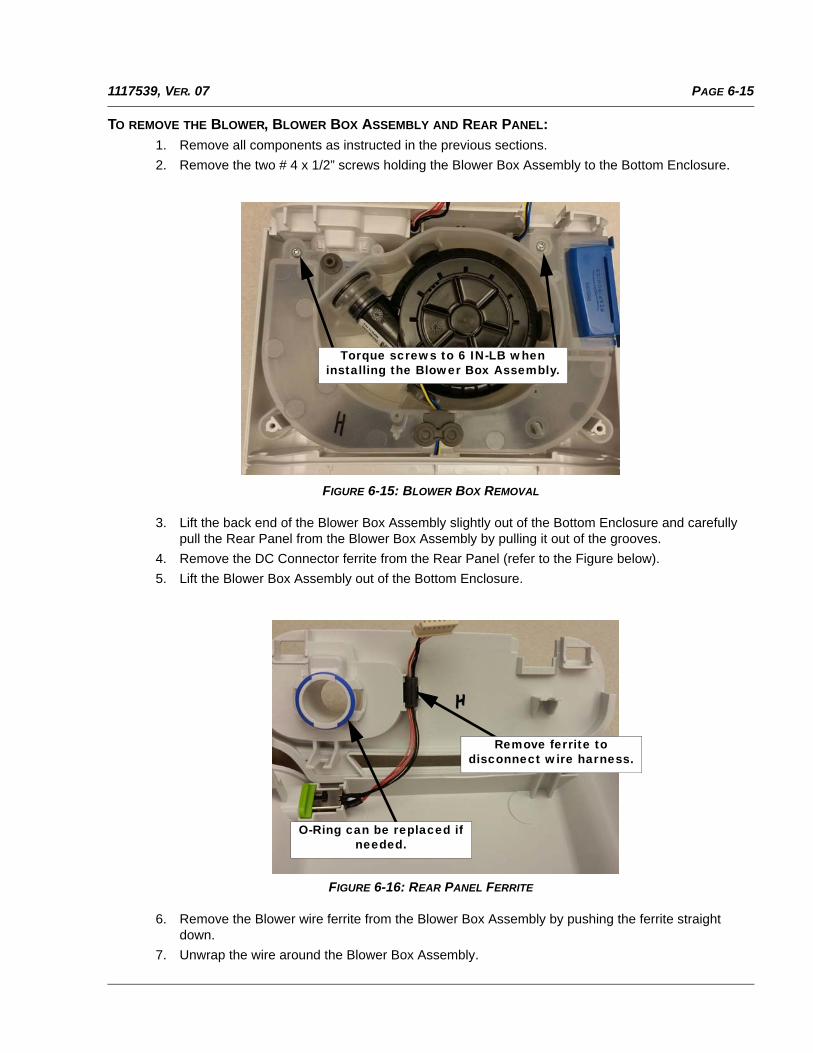
PAGE 6-151117539, VER. 07
TO REMOVE THE BLOWER, BLOWER BOX ASSEMBLY AND REAR PANEL:
1. Remove all components as instructed in the previous sections.
2. Remove the two # 4 x 1/2” screws holding the Blower Box Assembly to the Bottom Enclosure.
FIGURE 6-15: BLOWER BOX REMOVAL
3. Lift the back end of the Blower Box Assembly slightly out of the Bottom Enclosure and carefullypull the Rear Panel from the Blower Box Assembly by pulling it out of the grooves.
4. Remove the DC Connector ferrite from the Rear Panel (refer to the Figure below).
5. Lift the Blower Box Assembly out of the Bottom Enclosure.
FIGURE 6-16: REAR PANEL FERRITE
6. Remove the Blower wire ferrite from the Blower Box Assembly by pushing the ferrite straightdown.
7. Unwrap the wire around the Blower Box Assembly.
Torque screws to 6 IN-LB when installing the Blower Box Assembly.
Remove ferrite to disconnect wire harness.
O-Ring can be replaced if needed.
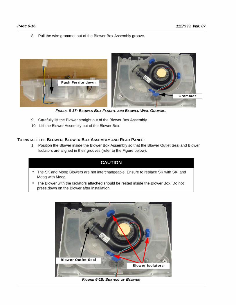
PAGE 6-16 1117539, VER. 07
8. Pull the wire grommet out of the Blower Box Assembly groove.
FIGURE 6-17: BLOWER BOX FERRITE AND BLOWER WIRE GROMMET
9. Carefully lift the Blower straight out of the Blower Box Assembly.
10. Lift the Blower Assembly out of the Blower Box.
TO INSTALL THE BLOWER, BLOWER BOX ASSEMBLY AND REAR PANEL:1. Position the Blower inside the Blower Box Assembly so that the Blower Outlet Seal and Blower
Isolators are aligned in their grooves (refer to the Figure below).
FIGURE 6-18: SEATING OF BLOWER
CAUTION
• The SK and Moog Blowers are not interchangeable. Ensure to replace SK with SK, and Moog with Moog.
• The Blower with the Isolators attached should be rested inside the Blower Box. Do not press down on the Blower after installation.
Push Ferrite down
Grommet
Blower IsolatorsBlower Outlet Seal
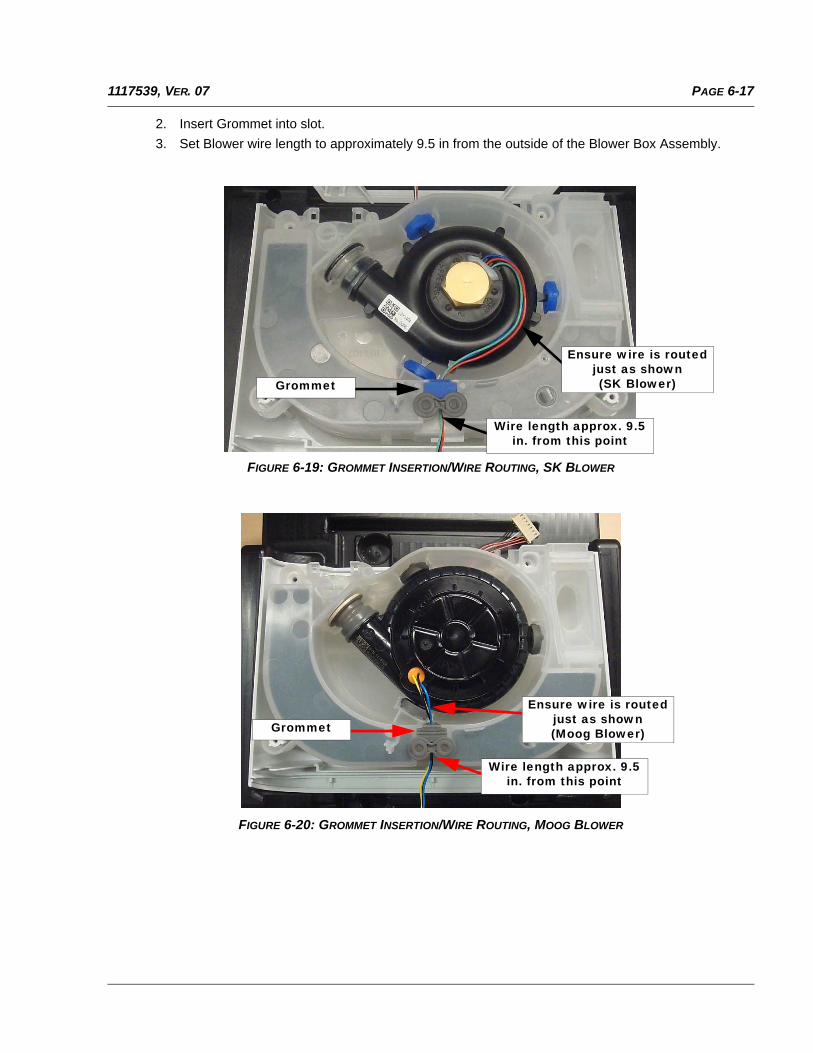
PAGE 6-171117539, VER. 07
2. Insert Grommet into slot.
3. Set Blower wire length to approximately 9.5 in from the outside of the Blower Box Assembly.
FIGURE 6-19: GROMMET INSERTION/WIRE ROUTING, SK BLOWER
FIGURE 6-20: GROMMET INSERTION/WIRE ROUTING, MOOG BLOWER
Grommet
Wire length approx. 9.5 in. from this point
Ensure wire is routed just as shown (SK Blower)
Wire length approx. 9.5 in. from this point
Ensure wire is routed just as shown (Moog Blower)Grommet
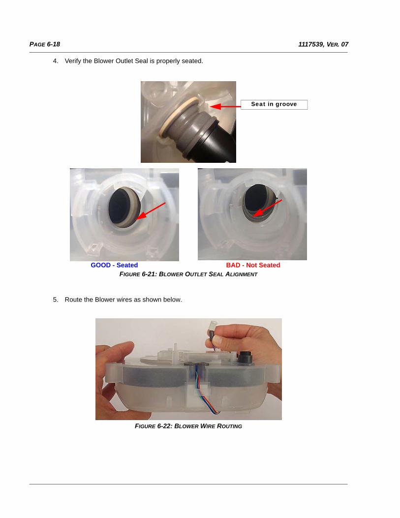
PAGE 6-18 1117539, VER. 07
4. Verify the Blower Outlet Seal is properly seated.
FIGURE 6-21: BLOWER OUTLET SEAL ALIGNMENT
5. Route the Blower wires as shown below.
FIGURE 6-22: BLOWER WIRE ROUTING
GOOD - Seated BAD - Not Seated
Seat in groove
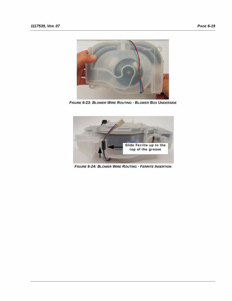
PAGE 6-191117539, VER. 07
FIGURE 6-23: BLOWER WIRE ROUTING - BLOWER BOX UNDERSIDE
FIGURE 6-24: BLOWER WIRE ROUTING - FERRITE INSERTION
Slide Ferrite up to the top of the groove
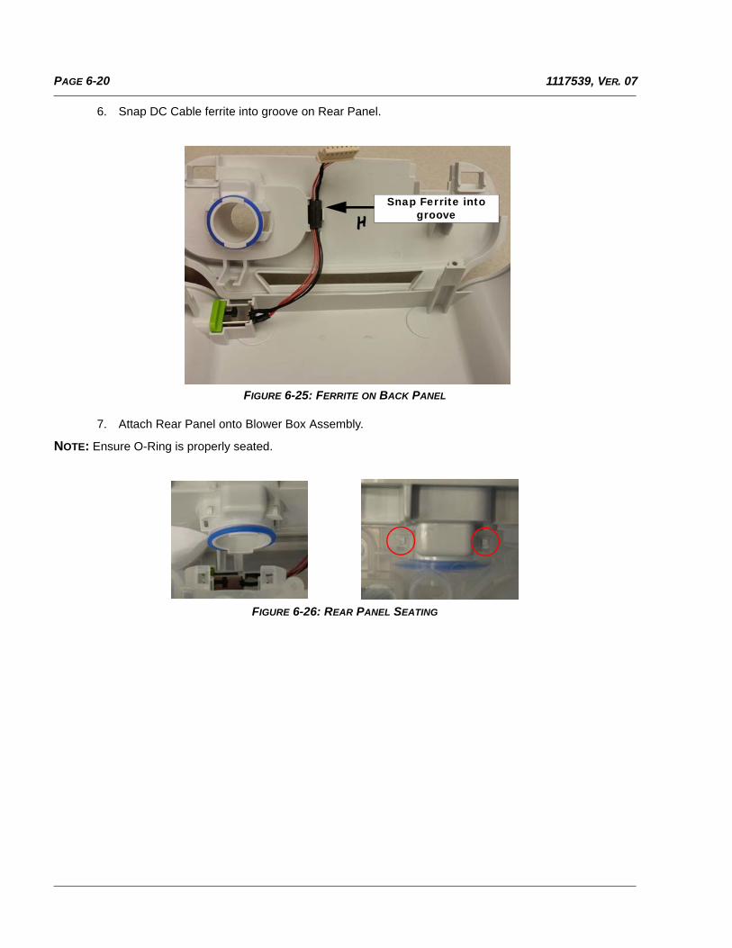
PAGE 6-20 1117539, VER. 07
6. Snap DC Cable ferrite into groove on Rear Panel.
FIGURE 6-25: FERRITE ON BACK PANEL
7. Attach Rear Panel onto Blower Box Assembly.
NOTE: Ensure O-Ring is properly seated.
FIGURE 6-26: REAR PANEL SEATING
Snap Ferrite into groove
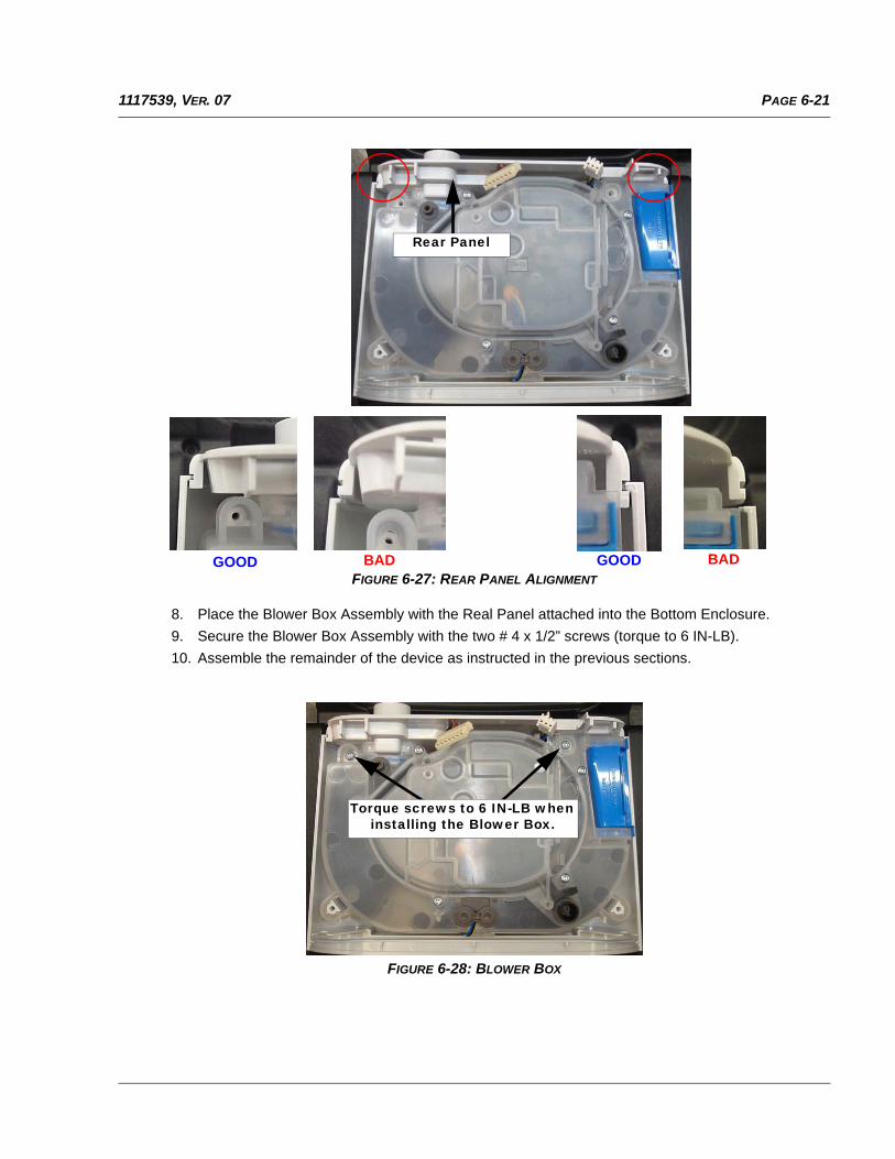
PAGE 6-211117539, VER. 07
FIGURE 6-27: REAR PANEL ALIGNMENT
8. Place the Blower Box Assembly with the Real Panel attached into the Bottom Enclosure.
9. Secure the Blower Box Assembly with the two # 4 x 1/2” screws (torque to 6 IN-LB).
10. Assemble the remainder of the device as instructed in the previous sections.
FIGURE 6-28: BLOWER BOX
Rear Panel
GOOD BAD GOOD BAD
Torque screws to 6 IN-LB when installing the Blower Box.
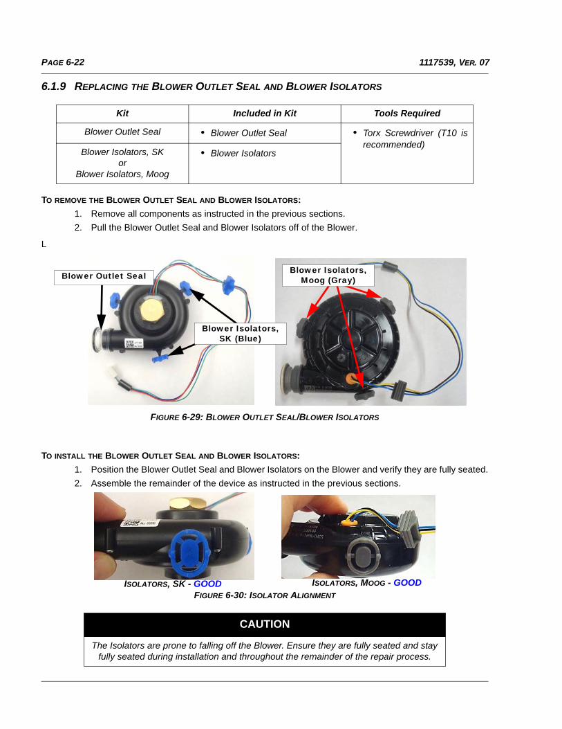
PAGE 6-22 1117539, VER. 07
6.1.9 REPLACING THE BLOWER OUTLET SEAL AND BLOWER ISOLATORS
TO REMOVE THE BLOWER OUTLET SEAL AND BLOWER ISOLATORS:
1. Remove all components as instructed in the previous sections.
2. Pull the Blower Outlet Seal and Blower Isolators off of the Blower.
L
FIGURE 6-29: BLOWER OUTLET SEAL/BLOWER ISOLATORS
TO INSTALL THE BLOWER OUTLET SEAL AND BLOWER ISOLATORS:
1. Position the Blower Outlet Seal and Blower Isolators on the Blower and verify they are fully seated.
2. Assemble the remainder of the device as instructed in the previous sections.
FIGURE 6-30: ISOLATOR ALIGNMENT
Kit Included in Kit Tools Required
Blower Outlet Seal • Blower Outlet Seal • Torx Screwdriver (T10 isrecommended)
Blower Isolators, SKor
Blower Isolators, Moog
• Blower Isolators
CAUTION
The Isolators are prone to falling off the Blower. Ensure they are fully seated and stay fully seated during installation and throughout the remainder of the repair process.
Blower Outlet Seal
Blower Isolators, SK (Blue)
Blower Isolators, Moog (Gray)
ISOLATORS, SK - GOOD ISOLATORS, MOOG - GOOD
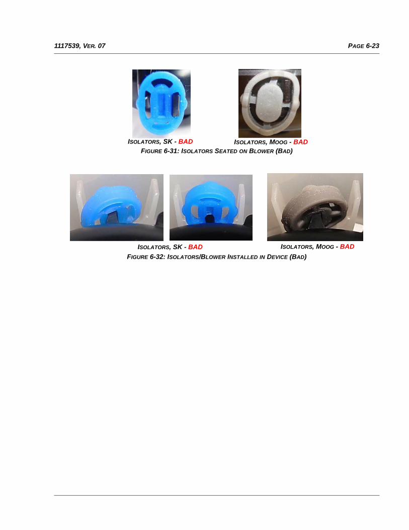
PAGE 6-231117539, VER. 07
FIGURE 6-31: ISOLATORS SEATED ON BLOWER (BAD)
FIGURE 6-32: ISOLATORS/BLOWER INSTALLED IN DEVICE (BAD)
ISOLATORS, SK - BAD ISOLATORS, MOOG - BAD
ISOLATORS, MOOG - BADISOLATORS, SK - BAD
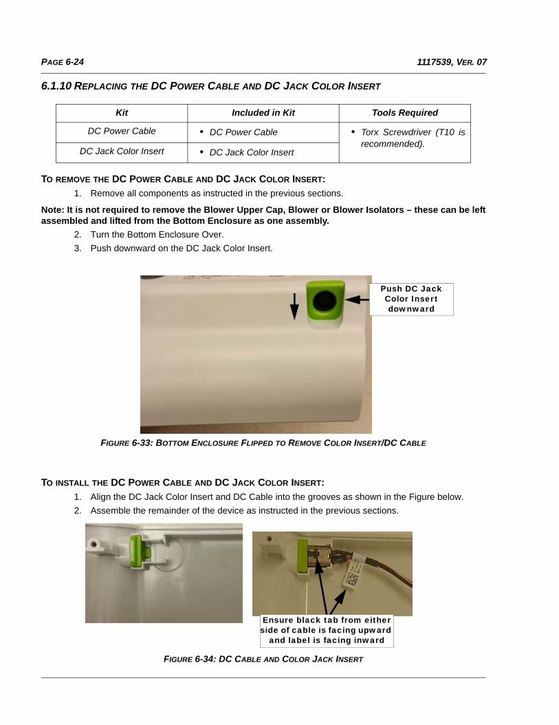
PAGE 6-24 1117539, VER. 07
6.1.10 REPLACING THE DC POWER CABLE AND DC JACK COLOR INSERT
TO REMOVE THE DC POWER CABLE AND DC JACK COLOR INSERT:
1. Remove all components as instructed in the previous sections.
Note: It is not required to remove the Blower Upper Cap, Blower or Blower Isolators – these can be leftassembled and lifted from the Bottom Enclosure as one assembly.
2. Turn the Bottom Enclosure Over.
3. Push downward on the DC Jack Color Insert.
FIGURE 6-33: BOTTOM ENCLOSURE FLIPPED TO REMOVE COLOR INSERT/DC CABLE
TO INSTALL THE DC POWER CABLE AND DC JACK COLOR INSERT:
1. Align the DC Jack Color Insert and DC Cable into the grooves as shown in the Figure below.
2. Assemble the remainder of the device as instructed in the previous sections.
FIGURE 6-34: DC CABLE AND COLOR JACK INSERT
Kit Included in Kit Tools Required
DC Power Cable • DC Power Cable • Torx Screwdriver (T10 isrecommended).
DC Jack Color Insert • DC Jack Color Insert
Push DC Jack Color Insert downward
Ensure black tab from either side of cable is facing upward
and label is facing inward
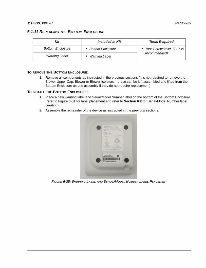
PAGE 6-251117539, VER. 07
6.1.11 REPLACING THE BOTTOM ENCLOSURE
TO REMOVE THE BOTTOM ENCLOSURE:
1. Remove all components as instructed in the previous sections (it is not required to remove theBlower Upper Cap, Blower or Blower Isolators – these can be left assembled and lifted from the Bottom Enclosure as one assembly if they do not require replacement).
TO INSTALL THE BOTTOM ENCLOSURE:1. Place a new warning label and Serial/Model Number label on the bottom of the Bottom Enclosure
(refer to Figure 6-31 for label placement and refer to Section 6.2 for Serial/Model Number label creation).
2. Assemble the remainder of the device as instructed in the previous sections.
FIGURE 6-35: WARNING LABEL AND SERIAL/MODEL NUMBER LABEL PLACEMENT
Kit Included in Kit Tools Required
Bottom Enclosure • Bottom Enclosure • Torx Screwdriver (T10 isrecommended).
Warning Label • Warning Label
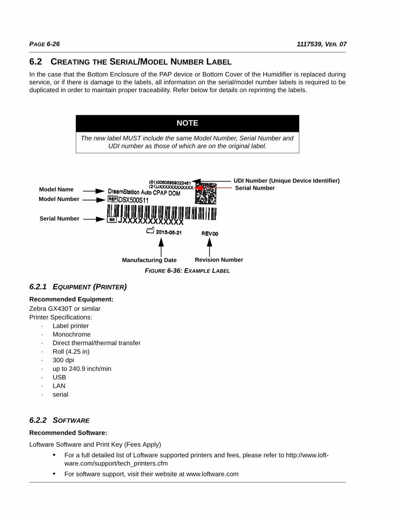
PAGE 6-26 1117539, VER. 07
6.2 CREATING THE SERIAL/MODEL NUMBER LABEL
In the case that the Bottom Enclosure of the PAP device or Bottom Cover of the Humidifier is replaced duringservice, or if there is damage to the labels, all information on the serial/model number labels is required to beduplicated in order to maintain proper traceability. Refer below for details on reprinting the labels.
FIGURE 6-36: EXAMPLE LABEL
6.2.1 EQUIPMENT (PRINTER)
Recommended Equipment:
Zebra GX430T or similarPrinter Specifications:
· Label printer· Monochrome· Direct thermal/thermal transfer· Roll (4.25 in)· 300 dpi· up to 240.9 inch/min· USB· LAN· serial
6.2.2 SOFTWARE
Recommended Software:
Loftware Software and Print Key (Fees Apply)
• For a full detailed list of Loftware supported printers and fees, please refer to http://www.loft-ware.com/support/tech_printers.cfm
• For software support, visit their website at www.loftware.com
NOTE
The new label MUST include the same Model Number, Serial Number and UDI number as those of which are on the original label.
Model Name
Model Number
Serial Number
UDI Number (Unique Device Identifier)Serial Number
Manufacturing Date Revision Number
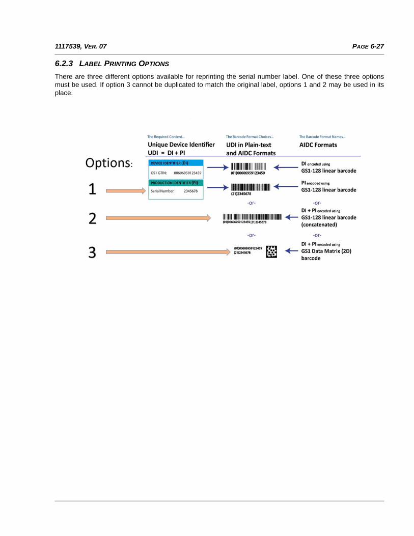
PAGE 6-271117539, VER. 07
6.2.3 LABEL PRINTING OPTIONS
There are three different options available for reprinting the serial number label. One of these three optionsmust be used. If option 3 cannot be duplicated to match the original label, options 1 and 2 may be used in itsplace.
PAGE 6-28 1117539, VER. 07
6.3 CLEANING THE THERAPY DEVICE FOR ONE USER
1. Unplug the therapy device, and wipe the outside of it with a cloth slightly dampened with water anda mild detergent. Let the device dry completely before plugging in the power cord.
2. Inspect the therapy device and all circuit parts for damage after cleaning. Replace any damagedparts.
6.4 CLEANING FOR MULTIPLE USERS
If you are using the therapy device and/or link module on multiple users, complete the following steps to cleanthe therapy device and/or link module before each new user.
1. Before cleaning, unplug the therapy device and remove the link module. Also remove the blue pol-len filter and light-blue disposable ultra-fine filter (if using).
2. Clean the outside of the therapy device and link module only. Use a cloth with one of the followingcleaning agents to clean the exterior of the device and link module:
• Mild Detergent
• 70% Isopropyl Alcohol
• DisCide Towelettes
• 10% Chlorine Bleach solution
3. Allow the therapy device to dry completely before plugging in the power cord and re-inserting thefilter(s).
WARNING
To avoid electrical shock, always unplug the powercord from the wall outlet before cleaning the device.
CAUTION
Do not immerse the device in liquid or allow any liquidto enter the enclosure, inlet filter, or any opening.
WARNING
If you are using the therapy device on multiple users, discard the bacteria filter each time thetherapy device is used on a different person.
NOTE
When using the therapy device on multiple users, it is recommended to use the “Reset Data”option before each new user. Refer to Reset Data under Device Settings in section 4.10.4 of thismanual for additional information.
NOTE
The device is not intended for high level disinfection.
PAGE 6-291117539, VER. 07
6.5 CLEANING OR REPLACING THE FILTERS
Under normal usage, you should clean the reusable blue pollen filter at least once every two weeks andreplace it with a new one every six months. The light-blue ultra-fine filter is disposable and should be replacedafter 30 nights of use or sooner if it appears dirty. DO NOT clean the ultra-fine filter.
This device has an automatic air filter reminder. Every 30 days, the device will display a message remindingyou to check your filters and replace them as directed.
1. If the device is operating, stop the airflow. Disconnect the device from the power source.
2. Remove the filter(s) from the device. Refer to section 4.7 of this manual.
3. Examine the filter(s) for cleanliness and integrity.
4. To clean the reusable blue pollen filter, first detach the light-blue ultra-fine filter if applicable, and set aside or dispose of as needed. Then take the reusable filter to the sink, turn it upside down, and run warm tap water through the white filter media to rinse away any debris. Next, lightly shake the filter to remove as much water as possible. Allow the filter to air dry completely before reinstall-ing it. If the reusable blue pollen filter is torn, replace it. (Only Philips Respironics-supplied filters should be used as replacement filters.)
5. If the light-blue ultra-fine filter is dirty or torn, replace it.
6. Reinstall the filters. Refer to section 4.7 of this manual.
CAUTION
Operating the device with a dirty filter may keep the systemfrom working properly and may damage the device.
NOTE
This message is a reminder only. The device does notdetect the performance of the filters nor does it recognizewhen a filter has been cleaned or replaced.
CAUTION
Dirty inlet filters may cause high operating temperatures that may affect deviceperformance. Regularly examine the inlet filters as needed for integrity and cleanliness.
CAUTION
Never install a wet filter into the device. You mustensure sufficient drying time for the cleaned filter.
PAGE 6-30 1117539, VER. 07
6.6 CLEANING THE TUBING
1. Clean the reusable tubing before first use and daily.
2. Disconnect the flexible tubing from the device.
3. For the 15 or 22 mm flexible tubing, gently wash the tubing in a solution of warm water and a mild detergent.
4. Rinse thoroughly and air dry.
5. Inspect the tubing for damage or wear (cracking, crazing, tears, punctures, etc.). Discard and replace if necessary.
6.7 PREVENTIVE MAINTENANCE
There is no preventive maintenance required for the device. The device does not require routine service.
NOTE
Refer to section 7.4 for instructions on how to clean the heated tube.
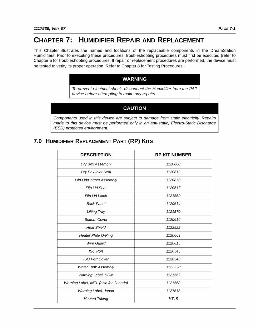
PAGE 7-11117539, VER. 07
CHAPTER 7: HUMIDIFIER REPAIR AND REPLACEMENT
This Chapter illustrates the names and locations of the replaceable components in the DreamStationHumidifiers. Prior to executing these procedures, troubleshooting procedures must first be executed (refer toChapter 5 for troubleshooting procedures. If repair or replacement procedures are performed, the device mustbe tested to verify its proper operation. Refer to Chapter 8 for Testing Procedures.
7.0 HUMIDIFIER REPLACEMENT PART (RP) KITS
WARNING
To prevent electrical shock, disconnect the Humidifier from the PAPdevice before attempting to make any repairs.
CAUTION
Components used in this device are subject to damage from static electricity. Repairsmade to this device must be performed only in an anti-static, Electro-Static Discharge(ESD) protected environment.
DESCRIPTION RP KIT NUMBER
Dry Box Assembly 1120668
Dry Box Inlet Seal 1120613
Flip Lid/Bottom Assembly 1120873
Flip Lid Seal 1120617
Flip Lid Latch 1121569
Back Panel 1120614
Lifting Tray 1121570
Bottom Cover 1120616
Heat Shield 1122522
Heater Plate O-Ring 1120669
Wire Guard 1120615
ISO Port 1126545
ISO Port Cover 1126543
Water Tank Assembly 1122520
Warning Label, DOM 1121567
Warning Label, INTL (also for Canada) 1121568
Warning Label, Japan 1127613
Heated Tubing HT15
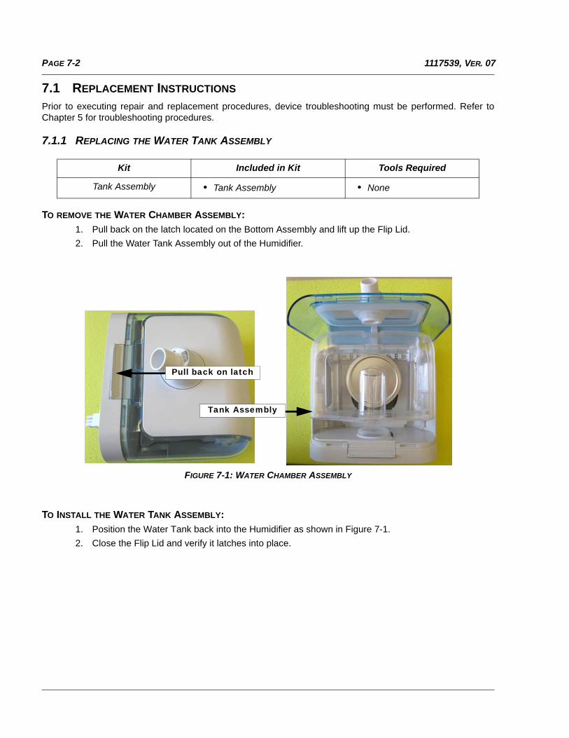
PAGE 7-2 1117539, VER. 07
7.1 REPLACEMENT INSTRUCTIONS
Prior to executing repair and replacement procedures, device troubleshooting must be performed. Refer toChapter 5 for troubleshooting procedures.
7.1.1 REPLACING THE WATER TANK ASSEMBLY
TO REMOVE THE WATER CHAMBER ASSEMBLY:
1. Pull back on the latch located on the Bottom Assembly and lift up the Flip Lid.
2. Pull the Water Tank Assembly out of the Humidifier.
FIGURE 7-1: WATER CHAMBER ASSEMBLY
TO INSTALL THE WATER TANK ASSEMBLY:
1. Position the Water Tank back into the Humidifier as shown in Figure 7-1.
2. Close the Flip Lid and verify it latches into place.
Kit Included in Kit Tools Required
Tank Assembly • Tank Assembly • None
Pull back on latch
Tank Assembly
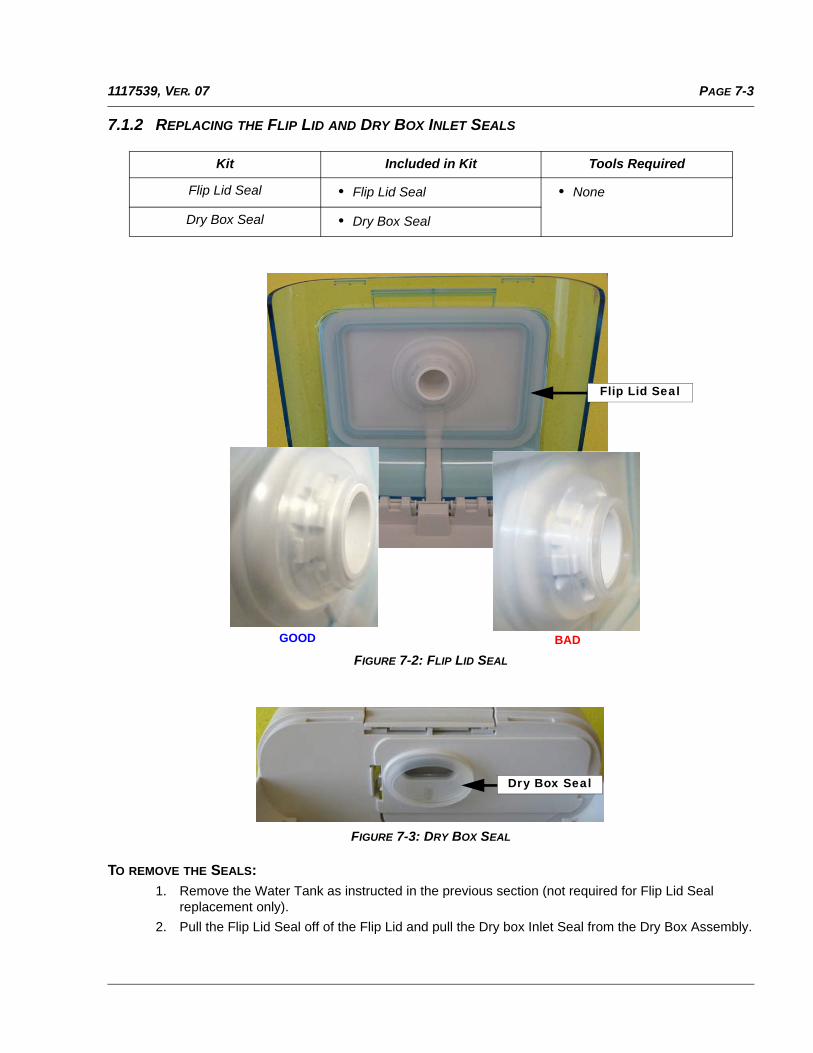
PAGE 7-31117539, VER. 07
7.1.2 REPLACING THE FLIP LID AND DRY BOX INLET SEALS
FIGURE 7-2: FLIP LID SEAL
FIGURE 7-3: DRY BOX SEAL
TO REMOVE THE SEALS:1. Remove the Water Tank as instructed in the previous section (not required for Flip Lid Seal
replacement only).
2. Pull the Flip Lid Seal off of the Flip Lid and pull the Dry box Inlet Seal from the Dry Box Assembly.
Kit Included in Kit Tools Required
Flip Lid Seal • Flip Lid Seal • None
Dry Box Seal • Dry Box Seal
Flip Lid Seal
GOOD BAD
Dry Box Seal
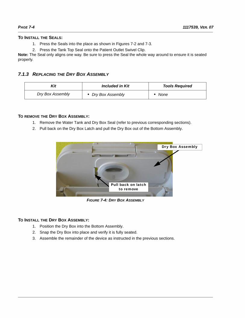
PAGE 7-4 1117539, VER. 07
TO INSTALL THE SEALS:
1. Press the Seals into the place as shown in Figures 7-2 and 7-3.
2. Press the Tank Top Seal onto the Patient Outlet Swivel Clip.Note: The Seal only aligns one way. Be sure to press the Seal the whole way around to ensure it is seated properly.
7.1.3 REPLACING THE DRY BOX ASSEMBLY
TO REMOVE THE DRY BOX ASSEMBLY:1. Remove the Water Tank and Dry Box Seal (refer to previous corresponding sections).
2. Pull back on the Dry Box Latch and pull the Dry Box out of the Bottom Assembly.
FIGURE 7-4: DRY BOX ASSEMBLY
TO INSTALL THE DRY BOX ASSEMBLY:1. Position the Dry Box into the Bottom Assembly.
2. Snap the Dry Box into place and verify it is fully seated.
3. Assemble the remainder of the device as instructed in the previous sections.
Kit Included in Kit Tools Required
Dry Box Assembly • Dry Box Assembly • None
Pull back on latch to remove
Dry Box Assembly
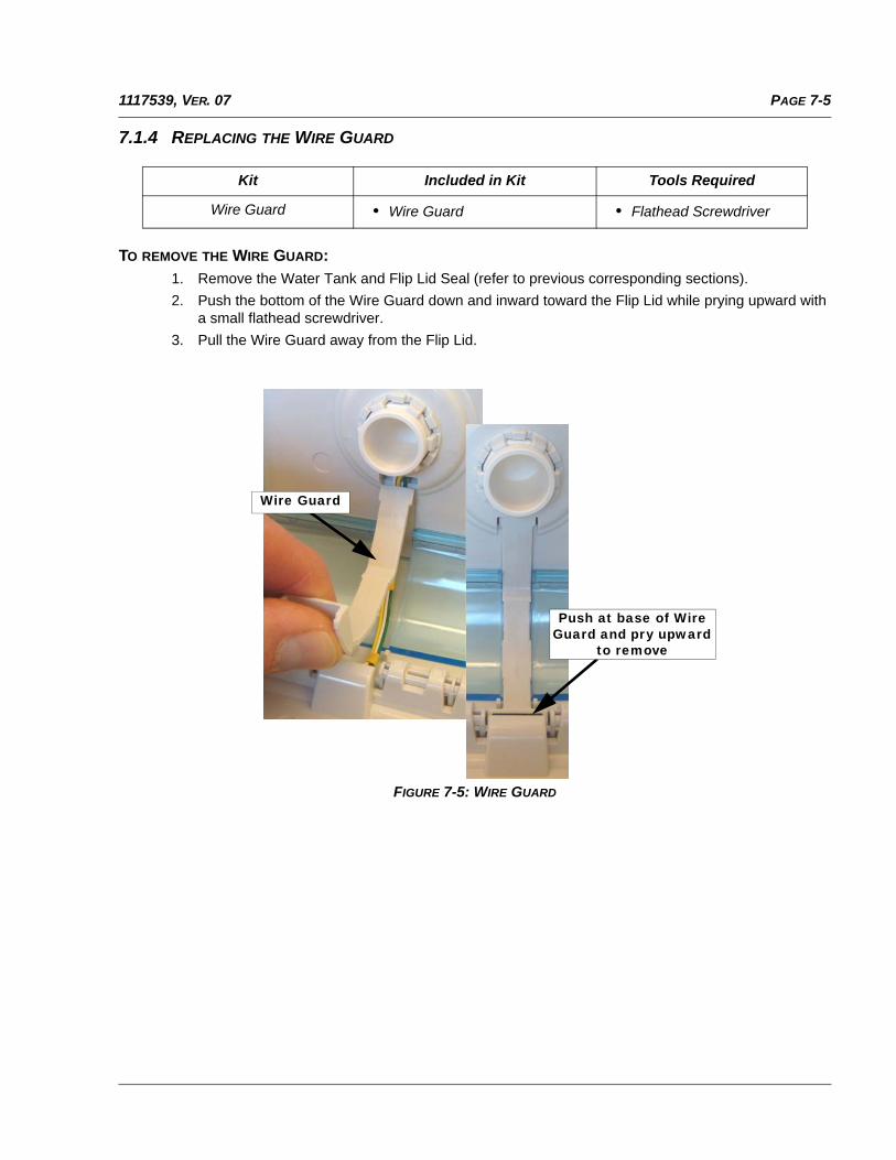
PAGE 7-51117539, VER. 07
7.1.4 REPLACING THE WIRE GUARD
TO REMOVE THE WIRE GUARD:
1. Remove the Water Tank and Flip Lid Seal (refer to previous corresponding sections).
2. Push the bottom of the Wire Guard down and inward toward the Flip Lid while prying upward witha small flathead screwdriver.
3. Pull the Wire Guard away from the Flip Lid.
FIGURE 7-5: WIRE GUARD
Kit Included in Kit Tools Required
Wire Guard • Wire Guard • Flathead Screwdriver
Wire Guard
Push at base of Wire Guard and pry upward
to remove
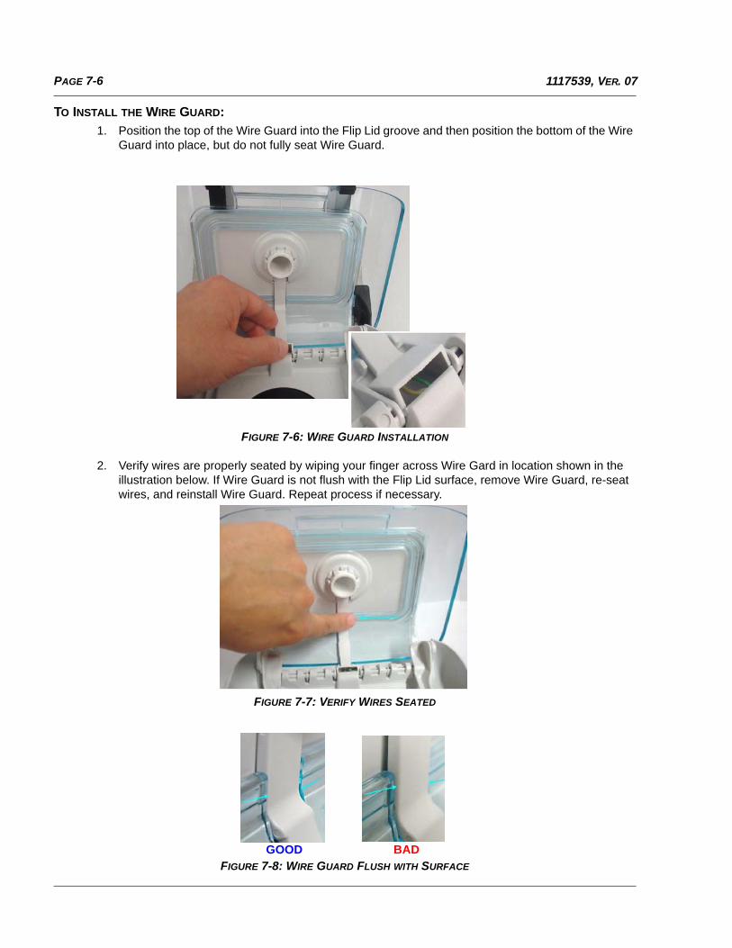
PAGE 7-6 1117539, VER. 07
TO INSTALL THE WIRE GUARD:
1. Position the top of the Wire Guard into the Flip Lid groove and then position the bottom of the Wire Guard into place, but do not fully seat Wire Guard.
FIGURE 7-6: WIRE GUARD INSTALLATION
2. Verify wires are properly seated by wiping your finger across Wire Gard in location shown in the illustration below. If Wire Guard is not flush with the Flip Lid surface, remove Wire Guard, re-seat wires, and reinstall Wire Guard. Repeat process if necessary.
FIGURE 7-7: VERIFY WIRES SEATED
FIGURE 7-8: WIRE GUARD FLUSH WITH SURFACE
GOOD BAD
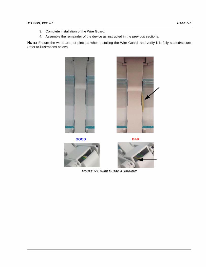
PAGE 7-71117539, VER. 07
3. Complete installation of the Wire Guard.
4. Assemble the remainder of the device as instructed in the previous sections.
NOTE: Ensure the wires are not pinched when installing the Wire Guard, and verify it is fully seated/secure(refer to illustrations below).
FIGURE 7-9: WIRE GUARD ALIGNMENT
GOOD BAD
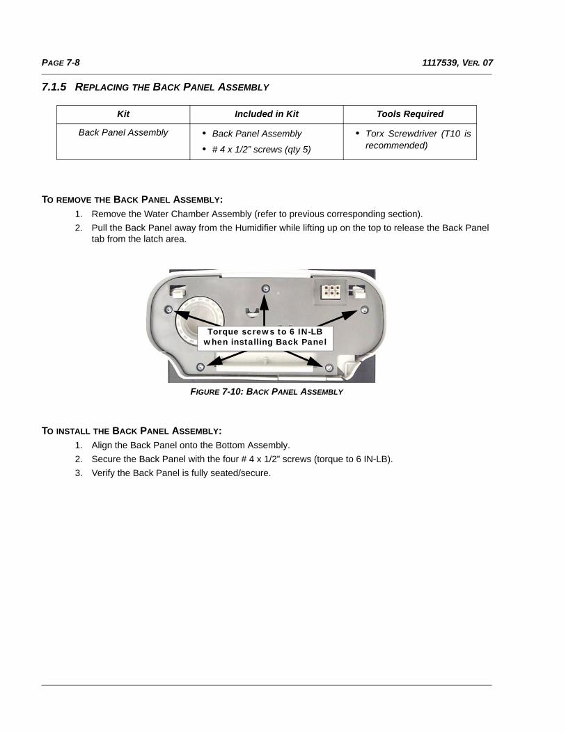
PAGE 7-8 1117539, VER. 07
7.1.5 REPLACING THE BACK PANEL ASSEMBLY
TO REMOVE THE BACK PANEL ASSEMBLY:
1. Remove the Water Chamber Assembly (refer to previous corresponding section).
2. Pull the Back Panel away from the Humidifier while lifting up on the top to release the Back Paneltab from the latch area.
FIGURE 7-10: BACK PANEL ASSEMBLY
TO INSTALL THE BACK PANEL ASSEMBLY:1. Align the Back Panel onto the Bottom Assembly.
2. Secure the Back Panel with the four # 4 x 1/2” screws (torque to 6 IN-LB).
3. Verify the Back Panel is fully seated/secure.
Kit Included in Kit Tools Required
Back Panel Assembly • Back Panel Assembly
• # 4 x 1/2” screws (qty 5)
• Torx Screwdriver (T10 isrecommended)
Torque screws to 6 IN-LB when installing Back Panel
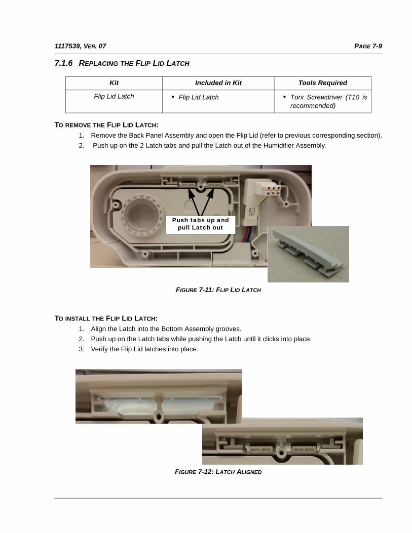
PAGE 7-91117539, VER. 07
7.1.6 REPLACING THE FLIP LID LATCH
TO REMOVE THE FLIP LID LATCH:
1. Remove the Back Panel Assembly and open the Flip Lid (refer to previous corresponding section).
2. Push up on the 2 Latch tabs and pull the Latch out of the Humidifier Assembly.
FIGURE 7-11: FLIP LID LATCH
TO INSTALL THE FLIP LID LATCH:
1. Align the Latch into the Bottom Assembly grooves.
2. Push up on the Latch tabs while pushing the Latch until it clicks into place.
3. Verify the Flip Lid latches into place.
FIGURE 7-12: LATCH ALIGNED
Kit Included in Kit Tools Required
Flip Lid Latch • Flip Lid Latch • Torx Screwdriver (T10 isrecommended)
Push tabs up and pull Latch out
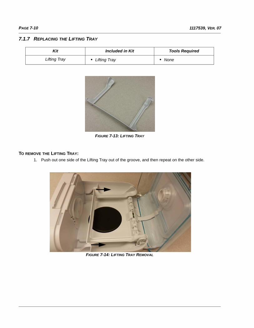
PAGE 7-10 1117539, VER. 07
7.1.7 REPLACING THE LIFTING TRAY
FIGURE 7-13: LIFTING TRAY
TO REMOVE THE LIFTING TRAY:1. Push out one side of the Lifting Tray out of the groove, and then repeat on the other side.
FIGURE 7-14: LIFTING TRAY REMOVAL
Kit Included in Kit Tools Required
Lifting Tray • Lifting Tray • None
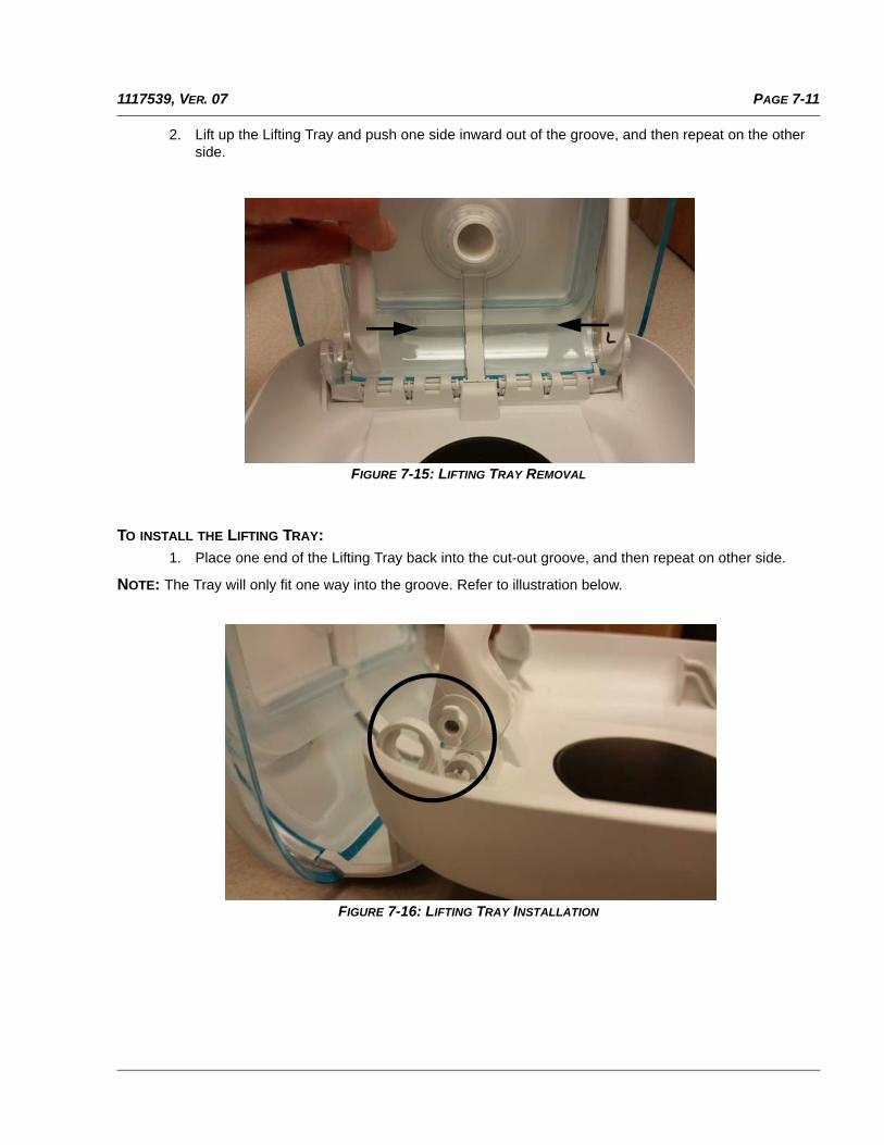
PAGE 7-111117539, VER. 07
2. Lift up the Lifting Tray and push one side inward out of the groove, and then repeat on the other side.
FIGURE 7-15: LIFTING TRAY REMOVAL
TO INSTALL THE LIFTING TRAY:1. Place one end of the Lifting Tray back into the cut-out groove, and then repeat on other side.
NOTE: The Tray will only fit one way into the groove. Refer to illustration below.
FIGURE 7-16: LIFTING TRAY INSTALLATION
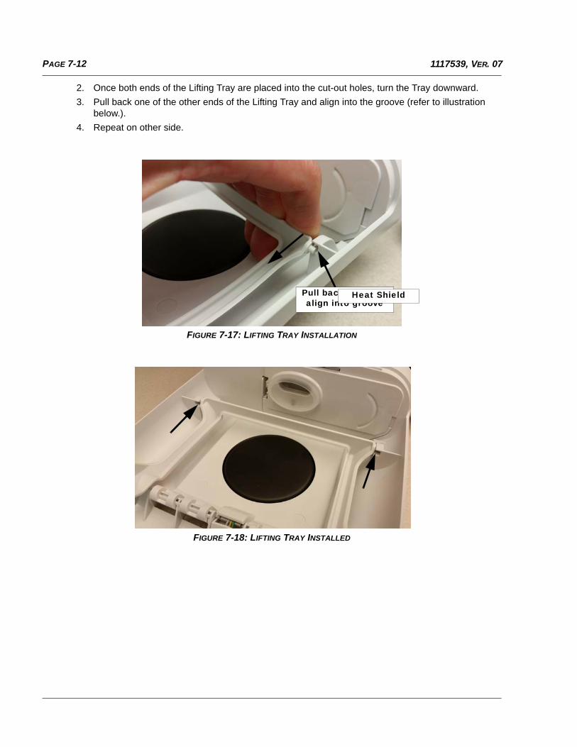
PAGE 7-12 1117539, VER. 07
2. Once both ends of the Lifting Tray are placed into the cut-out holes, turn the Tray downward.
3. Pull back one of the other ends of the Lifting Tray and align into the groove (refer to illustration below.).
4. Repeat on other side.
FIGURE 7-17: LIFTING TRAY INSTALLATION
FIGURE 7-18: LIFTING TRAY INSTALLED
Pull back Tray and align into groove
Heat Shield
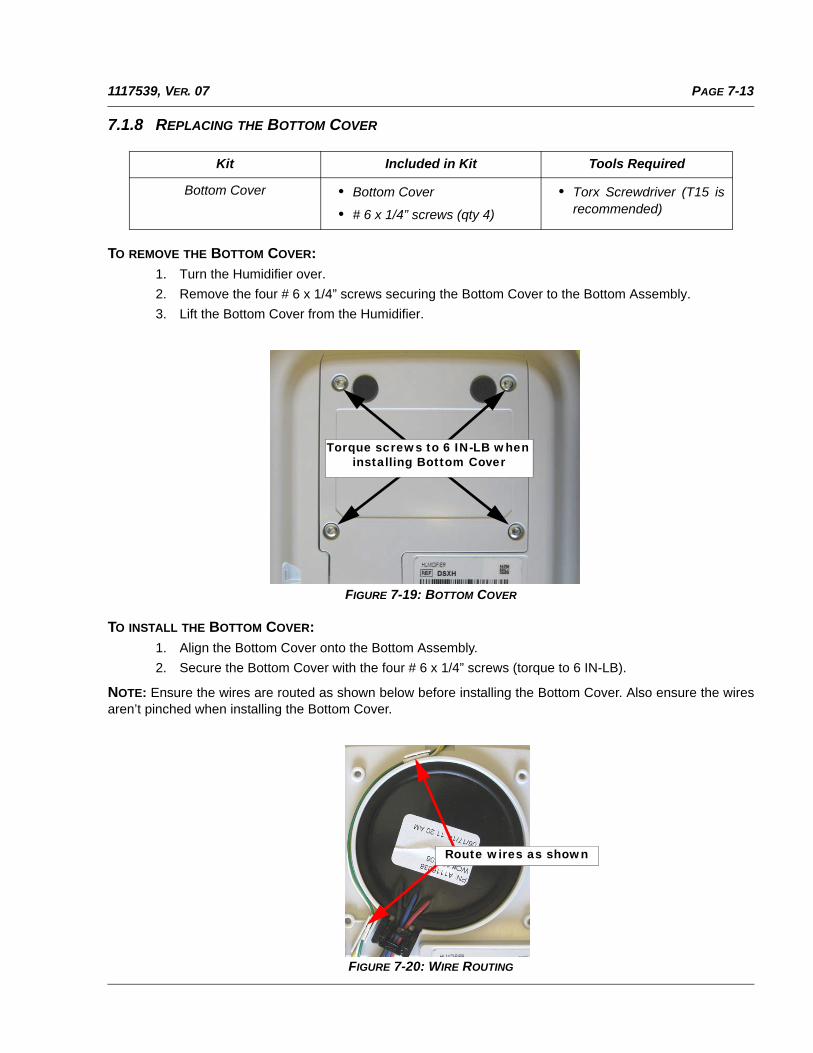
PAGE 7-131117539, VER. 07
7.1.8 REPLACING THE BOTTOM COVER
TO REMOVE THE BOTTOM COVER:1. Turn the Humidifier over.
2. Remove the four # 6 x 1/4” screws securing the Bottom Cover to the Bottom Assembly.
3. Lift the Bottom Cover from the Humidifier.
FIGURE 7-19: BOTTOM COVER
TO INSTALL THE BOTTOM COVER:
1. Align the Bottom Cover onto the Bottom Assembly.
2. Secure the Bottom Cover with the four # 6 x 1/4” screws (torque to 6 IN-LB).
NOTE: Ensure the wires are routed as shown below before installing the Bottom Cover. Also ensure the wiresaren’t pinched when installing the Bottom Cover.
FIGURE 7-20: WIRE ROUTING
Kit Included in Kit Tools Required
Bottom Cover • Bottom Cover
• # 6 x 1/4” screws (qty 4)
• Torx Screwdriver (T15 isrecommended)
Torque screws to 6 IN-LB when installing Bottom Cover
Route wires as shown
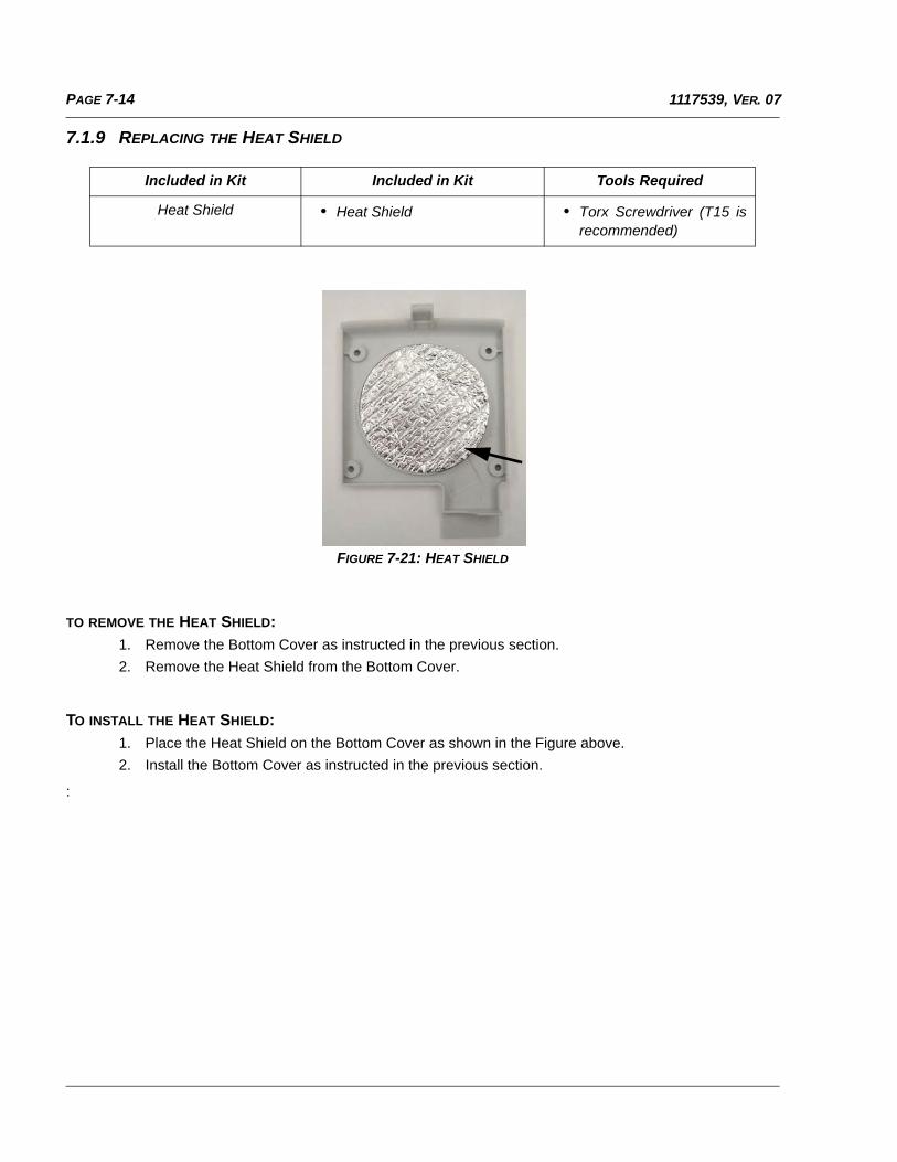
PAGE 7-14 1117539, VER. 07
7.1.9 REPLACING THE HEAT SHIELD
FIGURE 7-21: HEAT SHIELD
TO REMOVE THE HEAT SHIELD:1. Remove the Bottom Cover as instructed in the previous section.
2. Remove the Heat Shield from the Bottom Cover.
TO INSTALL THE HEAT SHIELD:
1. Place the Heat Shield on the Bottom Cover as shown in the Figure above.
2. Install the Bottom Cover as instructed in the previous section.
:
Included in Kit Included in Kit Tools Required
Heat Shield • Heat Shield • Torx Screwdriver (T15 isrecommended)
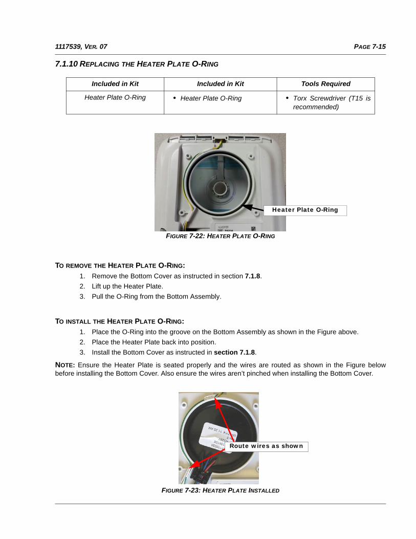
PAGE 7-151117539, VER. 07
7.1.10 REPLACING THE HEATER PLATE O-RING
FIGURE 7-22: HEATER PLATE O-RING
TO REMOVE THE HEATER PLATE O-RING:
1. Remove the Bottom Cover as instructed in section 7.1.8.
2. Lift up the Heater Plate.
3. Pull the O-Ring from the Bottom Assembly.
TO INSTALL THE HEATER PLATE O-RING:
1. Place the O-Ring into the groove on the Bottom Assembly as shown in the Figure above.
2. Place the Heater Plate back into position.
3. Install the Bottom Cover as instructed in section 7.1.8.
NOTE: Ensure the Heater Plate is seated properly and the wires are routed as shown in the Figure belowbefore installing the Bottom Cover. Also ensure the wires aren’t pinched when installing the Bottom Cover.
FIGURE 7-23: HEATER PLATE INSTALLED
Included in Kit Included in Kit Tools Required
Heater Plate O-Ring • Heater Plate O-Ring • Torx Screwdriver (T15 isrecommended)
Heater Plate O-Ring
Route wires as shown
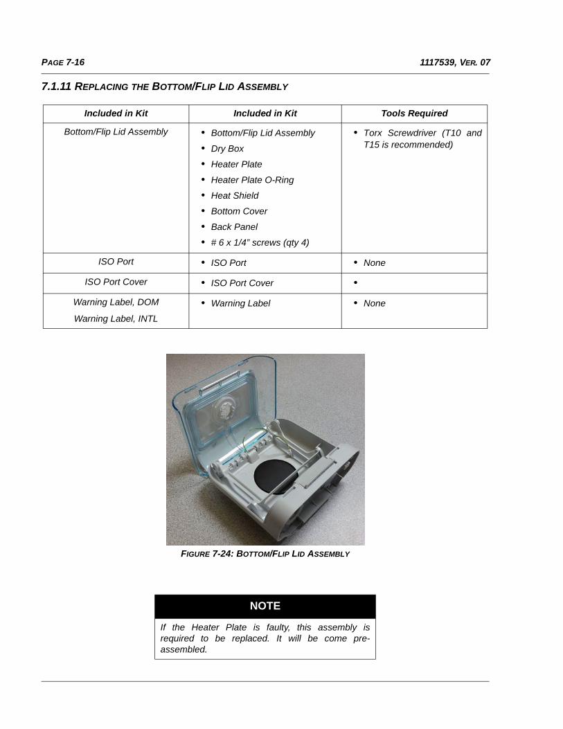
PAGE 7-16 1117539, VER. 07
7.1.11 REPLACING THE BOTTOM/FLIP LID ASSEMBLY
FIGURE 7-24: BOTTOM/FLIP LID ASSEMBLY
Included in Kit Included in Kit Tools Required
Bottom/Flip Lid Assembly • Bottom/Flip Lid Assembly
• Dry Box
• Heater Plate
• Heater Plate O-Ring
• Heat Shield
• Bottom Cover
• Back Panel
• # 6 x 1/4” screws (qty 4)
• Torx Screwdriver (T10 andT15 is recommended)
ISO Port • ISO Port • None
ISO Port Cover • ISO Port Cover •
Warning Label, DOM
Warning Label, INTL
• Warning Label • None
NOTE
If the Heater Plate is faulty, this assembly isrequired to be replaced. It will be come pre-assembled.
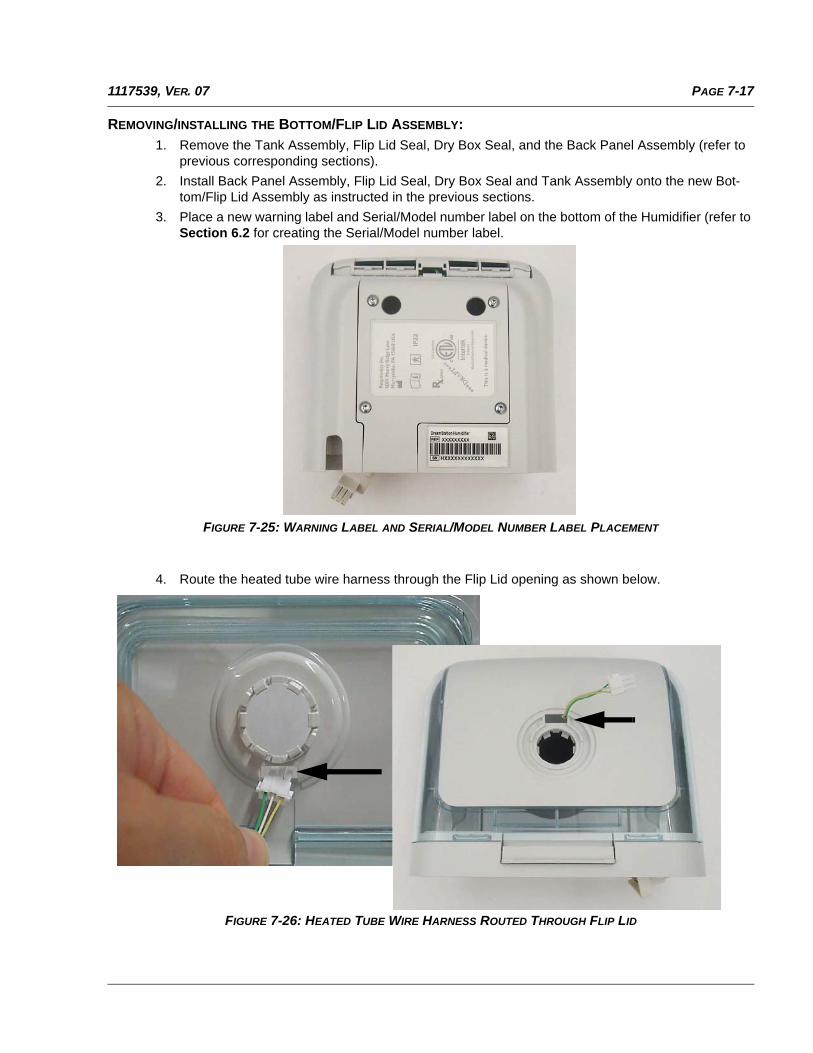
PAGE 7-171117539, VER. 07
REMOVING/INSTALLING THE BOTTOM/FLIP LID ASSEMBLY:
1. Remove the Tank Assembly, Flip Lid Seal, Dry Box Seal, and the Back Panel Assembly (refer to previous corresponding sections).
2. Install Back Panel Assembly, Flip Lid Seal, Dry Box Seal and Tank Assembly onto the new Bot-tom/Flip Lid Assembly as instructed in the previous sections.
3. Place a new warning label and Serial/Model number label on the bottom of the Humidifier (refer to Section 6.2 for creating the Serial/Model number label.
FIGURE 7-25: WARNING LABEL AND SERIAL/MODEL NUMBER LABEL PLACEMENT
4. Route the heated tube wire harness through the Flip Lid opening as shown below.
FIGURE 7-26: HEATED TUBE WIRE HARNESS ROUTED THROUGH FLIP LID
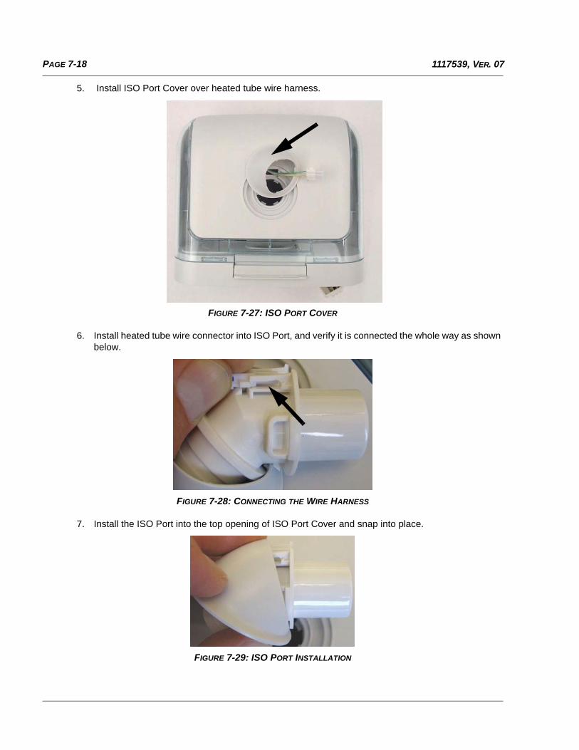
PAGE 7-18 1117539, VER. 07
5. Install ISO Port Cover over heated tube wire harness.
FIGURE 7-27: ISO PORT COVER
6. Install heated tube wire connector into ISO Port, and verify it is connected the whole way as shown below.
FIGURE 7-28: CONNECTING THE WIRE HARNESS
7. Install the ISO Port into the top opening of ISO Port Cover and snap into place.
FIGURE 7-29: ISO PORT INSTALLATION
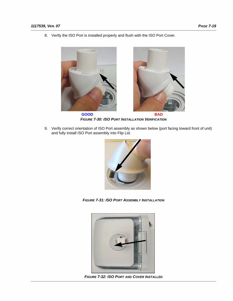
PAGE 7-191117539, VER. 07
8. Verify the ISO Port is installed properly and flush with the ISO Port Cover.
FIGURE 7-30: ISO PORT INSTALLATION VERIFICATION
9. Verify correct orientation of ISO Port assembly as shown below (port facing toward front of unit) and fully install ISO Port assembly into Flip Lid.
FIGURE 7-31: ISO PORT ASSEMBLY INSTALLATION
FIGURE 7-32: ISO PORT AND COVER INSTALLED
GOOD BAD
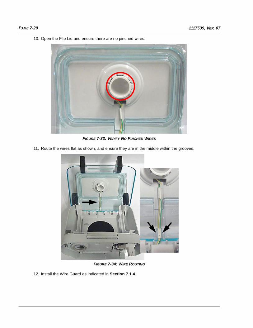
PAGE 7-20 1117539, VER. 07
10. Open the Flip Lid and ensure there are no pinched wires.
FIGURE 7-33: VERIFY NO PINCHED WIRES
11. Route the wires flat as shown, and ensure they are in the middle within the grooves.
FIGURE 7-34: WIRE ROUTING
12. Install the Wire Guard as indicated in Section 7.1.4.
PAGE 7-211117539, VER. 07
7.2 CLEANING THE WATER TANK
Hand washing can be performed daily. Dishwashing can be performed once a week.
1. Turn the humidifier setting off, turn the therapy device off, and allow the heater plate and water to cool.
2. Open the humidifier lid with the release lever, and remove the water tank from the humidifier.
3. Wash the water tank in a solution of warm water and a mild liquid dishwashing detergent.
4. Rinse with clean water.
5. Wipe completely on the top and bottom and allow the water tank to air dry.
6. Inspect the water tank for damage. If the water tank show signs of wear or damage, replace the tank.
7.3 CLEANING THE HUMIDIFIER BASE
1. Clean the humidifier base and heater plate by wiping it with a damp cloth. Allow the platform to air dry before reconnecting to the therapy device.
2. Inspect the humidifier base for any damage and replace it if necessary.
3. Clean the humidifier outlet port by using a damp bottle brush or a damp cloth. Insert the brush or cloth approximately 2.75 inches (7 cm) into the outlet opening while cleaning.
WARNING
Allow the humidifier heater plate and water to cool down for approximately 15 minutesbefore removing the water tank. A burn may result from: touching the heater plate, comingin contact with the heated water, or touching the tank pan.
CAUTION
Use a mild liquid dishwashing detergent only for either hand washing or whenusing a dishwasher.
WARNING
Empty and clean the water tank daily to prevent mold and bacteria growth.
WARNINGS
• Allow the humidifier heater plate and water to cool down for approximately 15 minutesbefore removing the water tank. A burn may result from: touching the heater plate,coming in contact with the heated water, or touching the tank pan.
• Before cleaning the humidifier, always remove from the therapy device.
PAGE 7-22 1117539, VER. 07
7.4 CLEANING THE HEATED TUBING
1. Disconnect the heated tubing from the heated humidifier.
2. Gently wash the heated tubing, including connectors, in a solution of warm water and a mild dish washing detergent to adequately remove adhering substances from the tube and connectors.
3. Rinse thoroughly to remove all soap residue from the tube and connectors with water and allow to air dry. Make sure the tube and connectors are dry before next use.
4. Inspect the heated tubing for damage or wear (cracking, crazing, tears, punctures, etc.). Discard and replace if necessary.
7.5 HOSPITAL AND INSTITUTION DISINFECTION: WATER TANK, SEAL AND HEATED TUBING
If using the water tank, seal and heated tubing on multiple users, complete the following steps to clean anddisinfect the water tank, seal and heated tubing before each new user.
7.5.1 CLEANING PRIOR TO DISINFECTION
1. Gently wash the items (tank, seal and heated tubing) using Medizyme, or an equivalent enzymatic detergent, and a soft bristle brush to adequately remove adhering substances.
2. Rinse the items separately by immersing each in at least 3 gallons (11.4 liters) of water and agitate vigorously.
3. Remove each item from the water and allow the water to drain from tank, seal and heated tubing.
4. Air dry out of direct sunlight.
5. Visually inspect the tank, seal and heated tubing for cleanliness. Repeat the cleaning if not visually clean.
CAUTION
Only the hospital and institution cleaning and disinfection procedures listed in this manualare recommended by Respironics. Use of other cleaning and disinfecting processes, notspecified by Respironics, may affect the performance of the product.
NOTES
• Pay close attention to all corners and crevices.
• A brush is not necessary for the inside of the tube of theheated tubing.
NOTES
The tank, seal and heated tubing should each use a fresh 3gallons (11.4 liters) of water and cannot be rinsed together.
PAGE 7-231117539, VER. 07
7.5.2 DISINFECTION
The recommended disinfection methods are identified below.
• Thermal Disinfection: Immersion in a (tap) water bath at 75° C ± 2° C for 30 minutes
• Cidex
• Cidex OPA
7.5.3 AFTER DISINFECTION
1. Inspect the tank, seal and heated tubing for damage or wear (cracking, crazing, tears, or damage,etc.). Discard and replace if damaged.
2. After the final water rinse described in the chemical disinfection instructions, separately rinse thetank, seal and heated tubing a minimum of 1 time each in at least 3 gallons (11.4 liters) of water and air dry out of direct sunlight.
CAUTION
• Follow all instructions from the manufacturer of the treatment products. Any deviation fromthese instructions, the manufacturer’s instructions, or agents not listed in this guide mayimpact the performance of the product. Review all applicable instructions for additionalwarnings and cautions.A brush is not necessary for the inside of the tube of the heatedtubing.
• Treat the tank, seal and heated tubing as different medical devices when rinsing them withwater. For example, the tank, seal and heated tubing cannot be rinsed in the same volumeof water.
• Use 3 gallons (11.4 liters) as the rinse volume when following the instructions.
NOTES
Discoloration of the seal is normal after disinfection.
PAGE 8-11117539, VER. 07
CHAPTER 8: TESTING AND CALIBRATION
Final testing of a device is a mandatory requirement after any repairs are made to the device, or if the deviceenclosure has been opened for any reason. Please note that the firmware is updated using the below testsystem if it is not currently up-to-date.
8.1 REQUIRED EQUIPMENT
Hardware:
• DreamStation Power Supply, 80W, (PN 1118499), Qty 1 ea.
• DreamStation Serial Accessory Module (PN 1123881 or PN 1126240 (includes serial and micro-USB cables listed below)), Qty 1 ea.
• Serial RS232 Cable DB9F-DB9M, 6 ft (PN 1037268), Qty 1 ea.
• USB Cable, Type A to Micro B (PN 1104765), Qty. 1 ea.
• Hose 22mm-18 in. (PN 1008198), Qty 1 ea.
• 15mm Heated Tube (PN HT15), Qty 1 ea.
• German Leak Device (ISO Port) (PN 1127131), Qty 1 ea.
• Pollen Filter (PN 1122446), Qty 1 ea.
• SD Card (PN 1063859 - 10 pk), Qty 1 ea.
• Printer (network or local connection)
• PC with the following minimum requirements:
• Windows 7 32/64 Bit Operating System, Professional (Enterprise can be used for Philips net-work users only)
• 3.20 GHz Processor
• 100 GB Free hard drive space
• 8 GB RAM
• 1 serial port
• Minimum 4 USB port
• Keyboard, mouse and 17 inch monitor
• Supports 220 VAC +/- 10% and 50 Hz +/- 1Hz, or 120 VAC +/- 10% and 60 Hz +/- 1Hz power
Software (download and install from my.respironics.com):
• NI LabVIEW 2014 Support Package (located under the Utility Tools category)
• DreamStation Device Driver Package, Version 1.0 or higher (located under the DreamStation Ser-vice Tools and Documents category)
• DreamStation Field Service Application (FSA), Version 1.0 or higher (located under the DreamSta-tion Service Tools and Documents category)
NOTE
Testing must occur in a lab equipment environment only.
PAGE 8-2 1117539, VER. 07
8.2 TESTING PREREQUISITES
Prior to testing any DreamStation device, the following must be ensured:
1. The device error log must be cleared.
2. The device real time clock must be accurate.
3. The DreamStation base unit and Humidifier must both be at room temperature. Refer to Section 8.3 for testing environmental specifications.
Refer to Chapter 5 on using the Service Center Tools software to clear the device error log and to reset the realtime clock.
8.3 TESTING ENVIRONMENT SPECIFICATIONS
The DreamStation devices must be tested within the following temperature specifications:
41 º F to 95 º F (+5 º C to 35º C)
8.4 FINAL TESTING PROCEDURE
1. Download the NI LabVIEW 2014 Support Package from my.respironics.com, and install the soft-ware by accepting all license agreements and default installation locations.
2. Download the DreamStation Device Driver Package from my.respironics.com, and unzip the files to your PC.
3. Follow the installation instructions within the zip file to install the drivers.
4. Download the DreamStation Field Service Application (FSA) from my.respironics.com, and install the software by accepting all license agreements and default installation locations. The following icon will be created on your desktop:
5. Launch the Test Executive from your desktop by double-clicking on the icon.
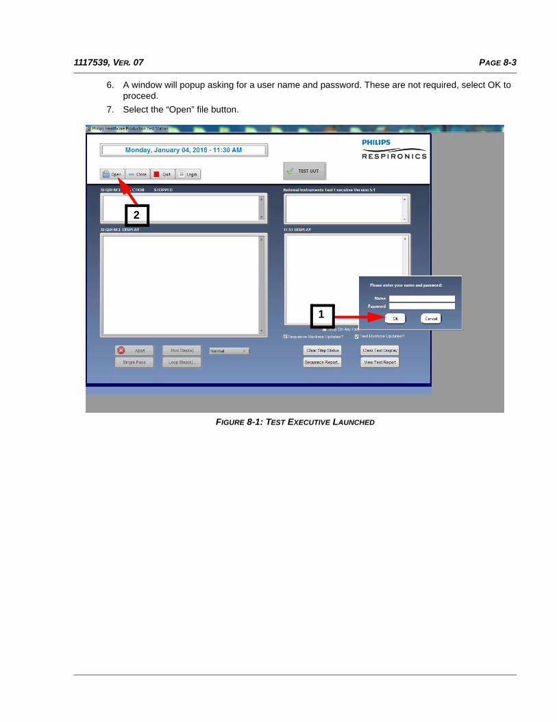
PAGE 8-31117539, VER. 07
6. A window will popup asking for a user name and password. These are not required, select OK to proceed.
7. Select the “Open” file button.
FIGURE 8-1: TEST EXECUTIVE LAUNCHED
1
2
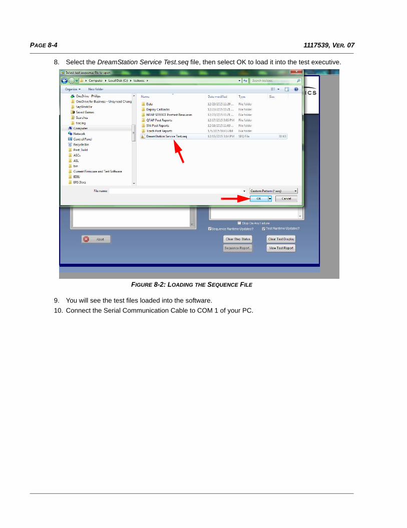
PAGE 8-4 1117539, VER. 07
8. Select the DreamStation Service Test.seq file, then select OK to load it into the test executive.
FIGURE 8-2: LOADING THE SEQUENCE FILE
9. You will see the test files loaded into the software.
10. Connect the Serial Communication Cable to COM 1 of your PC.
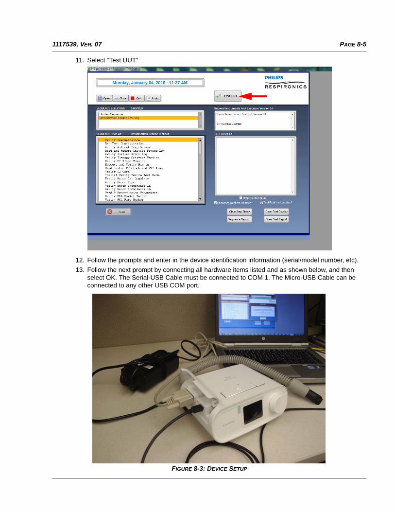
PAGE 8-51117539, VER. 07
11. Select “Test UUT”
12. Follow the prompts and enter in the device identification information (serial/model number, etc).
13. Follow the next prompt by connecting all hardware items listed and as shown below, and then select OK. The Serial-USB Cable must be connected to COM 1. The Micro-USB Cable can be connected to any other USB COM port.
FIGURE 8-3: DEVICE SETUP
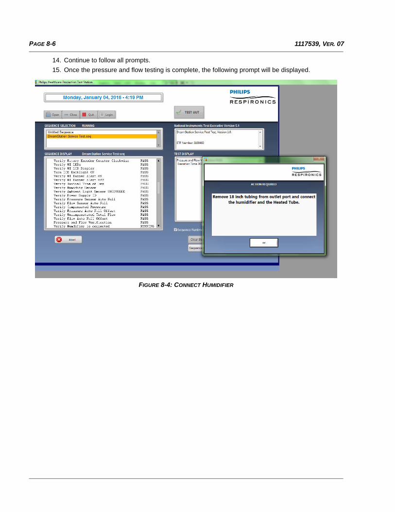
PAGE 8-6 1117539, VER. 07
14. Continue to follow all prompts.
15. Once the pressure and flow testing is complete, the following prompt will be displayed.
FIGURE 8-4: CONNECT HUMIDIFIER
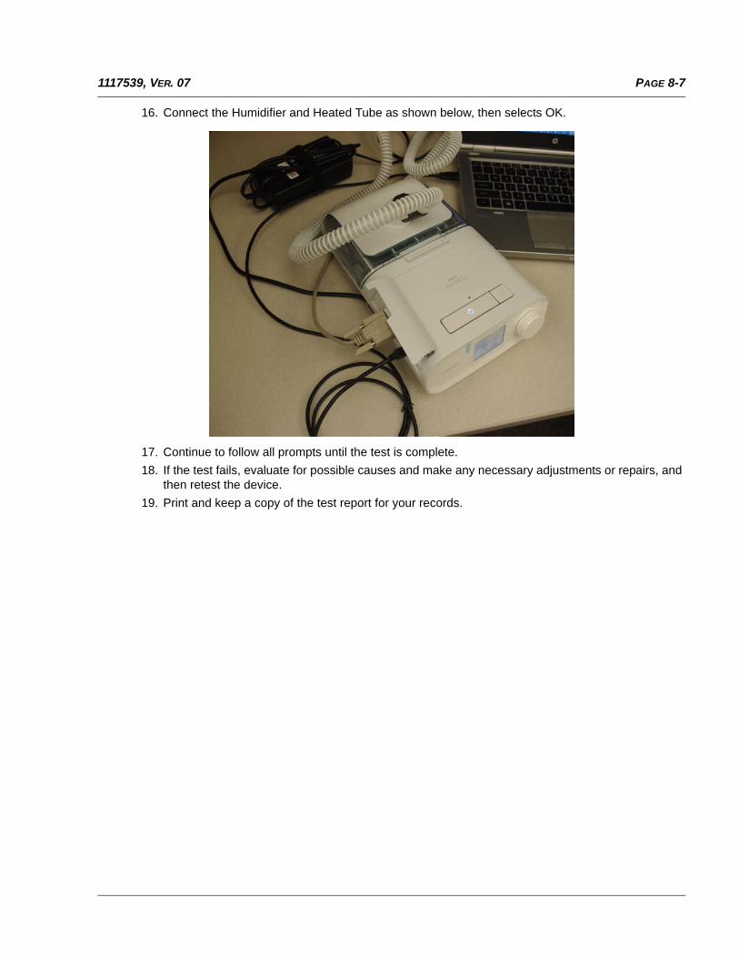
PAGE 8-71117539, VER. 07
16. Connect the Humidifier and Heated Tube as shown below, then selects OK.
17. Continue to follow all prompts until the test is complete.
18. If the test fails, evaluate for possible causes and make any necessary adjustments or repairs, and then retest the device.
19. Print and keep a copy of the test report for your records.

PAGE 8-8 1117539, VER. 07
This page intentionally blank.

NO. 1117539, VER. 07EMH 06/04/2016