Embed Size (px)
Citation preview
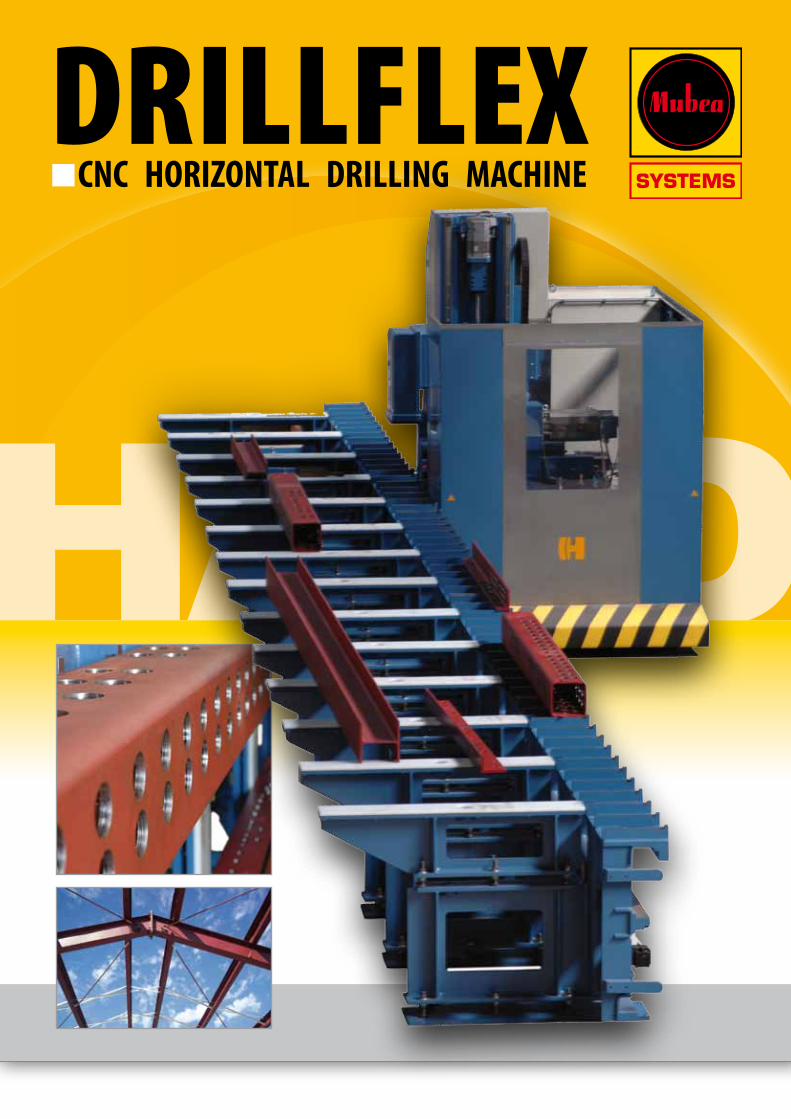
DRILLFLEXnCNC HORIZONTAL DRILLING MACHINE
DRILLFLEX
2
CNC PROFILE DRILLING MACHINES
MUBEA DRILLFLEX - DF 1100
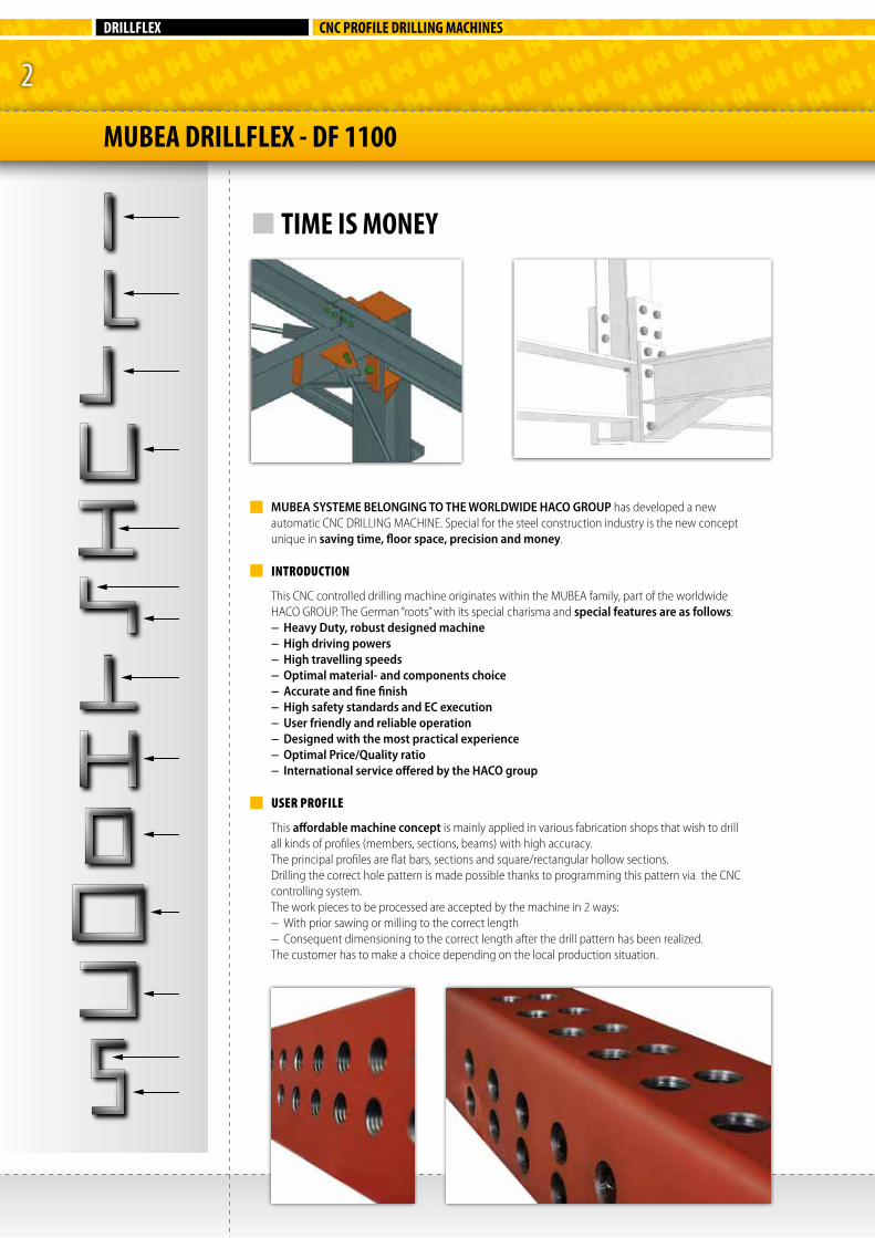
MUBEA SYSTEME BELONGING TO THE WORLDWIDE HACO GROUP has developed a new automatic CNC DRILLING MACHINE. Special for the steel construction industry is the new concept unique in saving time, floor space, precision and money.
INTRODUCTION
This CNC controlled drilling machine originates within the MUBEA family, part of the worldwide HACO GROUP. The German “roots” with its special charisma and special features are as follows:− Heavy Duty, robust designed machine− High driving powers− High travelling speeds− Optimal material- and components choice− Accurate and fine finish − High safety standards and EC execution− User friendly and reliable operation− Designed with the most practical experience− Optimal Price/Quality ratio− International service offered by the HACO group
USER PROFILE
This affordable machine concept is mainly applied in various fabrication shops that wish to drill all kinds of profiles (members, sections, beams) with high accuracy.The principal profiles are flat bars, sections and square/rectangular hollow sections. Drilling the correct hole pattern is made possible thanks to programming this pattern via the CNC controlling system. The work pieces to be processed are accepted by the machine in 2 ways: − With prior sawing or milling to the correct length− Consequent dimensioning to the correct length after the drill pattern has been realized.The customer has to make a choice depending on the local production situation.
n TIME IS MONEY
3
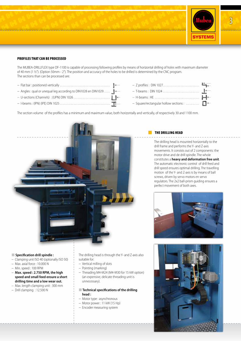
THE DRILLING HEAD
The drilling head is mounted horizontally to the drill frame and performs the Y- and Z-axis movements. It consists out of 2 components: the motor drive and de drill spindle. The whole constitutes a heavy and deformation free unit. The automatic electronic control of drill feed and drill speed ensures optimal drilling. The travelling motion of the Y- and Z-axis is by means of ball screws, driven by servo motors en servo regulators. The 2x2 ball-prism guiding ensures a perfect movement of both axes.
Specification drill spindle :− Clamping unit ISO 40 (optionally ISO 50)− Max. axial force : 10.000 N− Min. speed : 100 RPM− Max. speed : 2.750 RPM, the high
speed and small feed ensure a short drilling time and a low wear out.
− Max. length clamping unit : 300 mm− Drill clamping : 12.500 N
The drilling head is through the Y- and Z-axis also suitable for: − Vertical milling of slots− Pointing (marking)− Threading M4-M24 (M4-M30 for 15 kW option) (an expensive, delicate threading unit is
unnecessary).
Technical specifications of the drilling head :
− Motor type : asynchronous− Motor power : 11 kW (15 Hp)− Encoder measuring system
PROFILES THAT CAN BE PROCESSED
The MUBEA-DRILLFLEX type DF-1100 is capable of processing following profiles by means of horizontal drilling of holes with maximum diameter of 40 mm (1 ½”). (Option 50mm - 2”). The position and accuracy of the holes to be drilled is determined by the CNC program. The sections than can be processed are:
− Flat bar : positioned vertically . . . . . . . . . . . . . . . . . . . . . . . . . . . . . . . . . . . . .
− Angles : qual or unequal leg according to DIN1028 en DIN1029. . . . .
− U-sections (Channels) : (UPN) DIN 1026 . . . . . . . . . . . . . . . . . . . . . . . . . . .
− I-beams : (IPN) (IPE) DIN 1025 . . . . . . . . . . . . . . . . . . . . . . . . . . . . . . . . . . . . .
− Z profiles : DIN 1027. . . . . . . . . . . . . . . . . . . . . . . . . . .
− T-beams : DIN 1024 . . . . . . . . . . . . . . . . . . . . . . . . . . .
− H-beams : HE . . . . . . . . . . . . . . . . . . . . . . . . . . . . . . . . .
− Square/rectangular hollow sections : . . . . . . . . . .
The section volume of the profiles has a minimum and maximum value, both horizontally and vertically, of respectively 30 and 1100 mm.
DRILLFLEX
4
THE DRILL TABLE AND SUPPORTING SYSTEM
Together these items constitute the SUPPORTING SURFACE for the profiles to be processed. The supporting surface is leveled horizontally with high precision by means of a measuring device with LASER BEAM. This can only be accomplished quickly and precisely thanks to the very robust substructure of the separated table and supporting arms, provided with the necessary leveling bolts.The supporting surface needs to be plane both longitudi-nally and transversally since it forms the basic reference for the complete machine.
We get the following summary :− Highest flatness in both transversal and longitudinal direction. − Through the robust substructure consequently :• Novibrations• Nodeformations• Nolossofflatness
− Another, major reason for which the table unit must have a robust substructure, is the fact that it is supporting the travelling column, where deformations are not permitted.
− The milled table supports are mounted with an interval of 250mm and feature all an anti-slip reference tooth in order to enable proper profile clamping. The reference teeth forms a perpendicular reference in the length direction of the machine, the ZERO LINE.
− Standard dimensions are :• Basiclength:12.200mm(40Ft.)
total length: 14.450 mm (47,4 Ft.)• Widthdrilltable:280mm(11”)
width table supports: 1240 mm (48,8”)− Total width : 1.520 mm (60”)• Heightreferenceteeth:10mm(3∕8”)• Workingheight:980mm(39”)• Forsectionsfrom30upto1100mm(1,18”-43”)
The width of the table supports enables buffering some profiles when the machine is drilling. Max. weight on the table supports: ±10 ton (22.000 lbs).
POWER RAIL
In the most modern and safe execution, this power rail is located underneath the drill table. The current is connected to a fixed point (at the right hand side ) via a main switch. When in ON position, the inside of the rail in under constant tension. The transmission to the electrical cabinet is realized by means of TOW CONTACTS that run with the traveling column. The whole entity is reliable, safe and clean. No disturbing cable chains and litter on the floor.
SENSORS FOR FINDING PROFILES
The machine is equiped with sensors to opticaly find the beginning of the profile and to measure the length of the drilbit.
SENSOR DRILL LENGTH
ANTI-SLIP TOOTH
SENSOR PROFILE BEGINNING
CNC PROFILE DRILLING MACHINES
MUBEA DRILLFLEX - DF 1100
5
LUBRICATING SYSTEMS
Machines require well designed lubrication systems.
The basic machine is provided with following systems:
− Centralized manual lubricating system to lubricate all important places with only 1 hand movement. (auto lubricating optionally)
− Drill- and threading unit lubrication: i.e. cooling of the cutting tools. Drills are cooled internally /externally, the threading unit is cooled externally only. Cooling is performed by means of an oil mist (micro-drop). This mist is produced by an independent lubricating group.
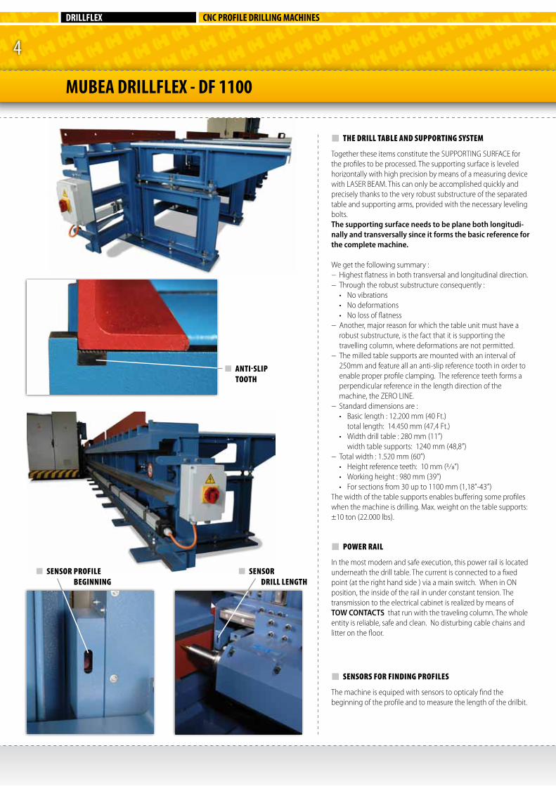
PROFILE MEASURING SYSTEM (optional)
This ingenious system is required to measure the bend of the profile. The value of the bend is measured by means of 1 or 2 sensors and an correction of the height of the hole to be drilled is performed automatically. In other words: the hole pattern follows the bend of the profile.
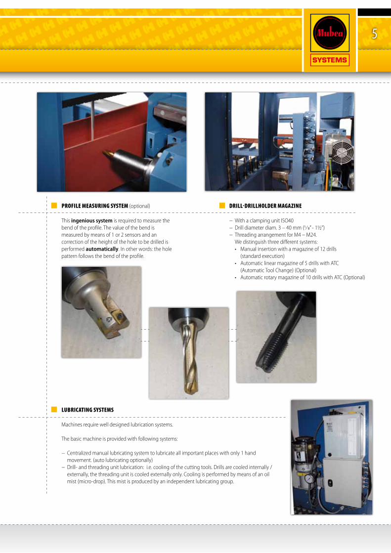
DRILL-DRILLHOLDER MAGAZINE
− With a clamping unit ISO40− Drill diameter diam. 3 – 40 mm (1∕8” - 1½”)− Threading arrangement for M4 – M24. We distinguish three different systems: • Manualinsertionwithamagazineof12drills
(standard execution)• Automaticlinearmagazineof5drillswithATC
(Automatic Tool Change) (Optional)• Automaticrotarymagazineof10drillswithATC(Optional)
DRILLFLEX
6
CNC PROFILE DRILLING MACHINES
THE TRAVELLING COLUMNThe travelling column is the most important part of the machine, supported by both table threads. The travelling column supports the following machine elements:
CNC-X-AXISHorizontal movement along the length direction via a rack and pinion drive system and 3.3 kW (4 Hp) motor, with a lubrication point on the rack. The horizontal working plane is provided with air blowers, brushes and scrapers in order to keep it clean. − Linear travelling speed 45 m/min (1.770 IPM).− Laser zero-point X-axis − The traveling column does not hit the floor surface ( it features only a springy supporting
roller). Externally, underneath the platform, a safety buffer is provided. This buffer stops the machine instantly when an obstacle on the floor is detected; an extremely reliable safety arrangement. The traveling column features a housing of metal sheets and transparent windows which allows to control the operation of the machine, as well as a door with electrical safety lock (EC).
CNC-Y-AXISThis is the horizontal longitudinal movement of the drilling head, through a ball screw drive system:− Stroke of the Y-axis : 550 mm (21,6”)− Linear travelling speed : 15 m/min (590 IPM)− Motor Power : 2.14 kW (3 Hp)− Ball screw drive system : diam. 40 x 5 m− 2 x ball-prism guiding : size 35 mmThe advantage of the Y-axis drive against a hydraulic push-movement, is the controlled drill spindle feed when drilling and especially when threading. In this case, a special threading unit is not necessary anymore and there is no danger for fracture. This means genuine synchronous threading. The application of modern hard metal cutting tools (drill with inserts) which allow a very short drill time is another big advantage of the principle of drilling with controlled drill spindle feed combined with high drill speeds (RPM). As an example: drilling a hole with diameter 40mm (1½”) in 10mm (3∕8“)profile thickness only requires 4.5 seconds.
CNC-Z-AXISThis is the vertical movement of the complete drilling unit :− Stroke (height) : 1100 mm (43,3”)− Ball screw drive system : D 40 x 10 mm− Motor Power: 3.3 KW (4 Hp)− Linear travelling speed : 30 m/min (1.180 IPM)− 2 x ball-prism guiding : size 35 mmThe Z-axis determines, together with the X-axis, in the vertical plane, the position of the hole to be drilled.
CLAMPING SYSTEMS
The machine houses 3 hydraulic clamping systems
1 - Clamping of the travelling column. This system clamps the traveling column by means of a hydraulic cylinder, prior to drilling, to the drilling table.− Clamping force : 65 KN− Cylinder stroke : 10 mm (3∕₈”)
2 - Clamping of the profile/work pieceThis system clamps the work piece immovable during the drilling operation.− Clamping force : 60 KN (14.600 Pd)− Cylinder stroke : 1.100 mm (43,3”)This clamping hammer contains also a vertical measuring system to measure the height of the profile.
3 - Clamping of the drill holder in the spindle of the drilling head with a clamping force of 5 KN (1.124 Pd).
MACHINE GUIDINGS
Since the traveling column is travelling on the guides of the table, it is obvious (once again) that the table substructure must be very robust. The horizontal and vertical thread of the drill table which support the travelling column via over dimensioned and adjustable eccentric roller bearings has an additional feature such as brushing and air blowing of drill chips. This results in a long lifetime of the threads, since they get not damaged. Dimensions of the roller bearings: − 4 x D 90 mm (3,54”)− 2 x D 160 mm (6,30”)
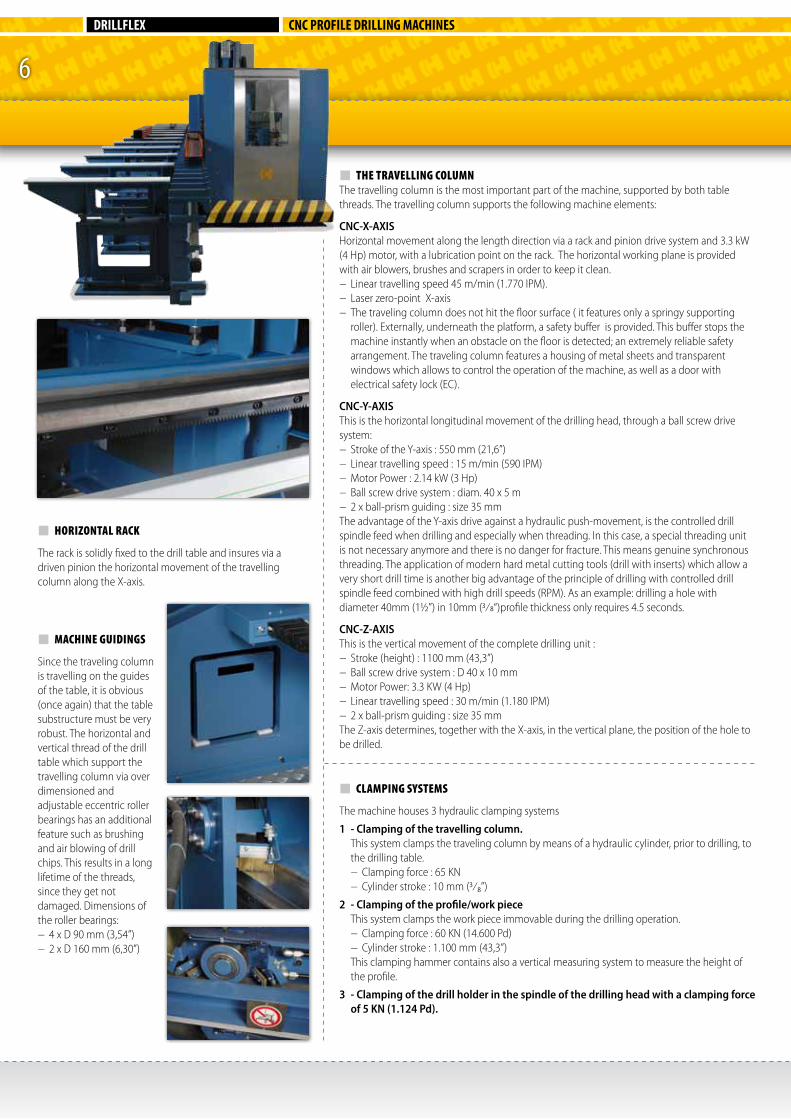
HORIZONTAL RACK
The rack is solidly fixed to the drill table and insures via a driven pinion the horizontal movement of the travelling column along the X-axis.
7
MUBEA DRILLFLEX - DF 1100
DIVERS TECHNICAL GROUPS
Hydraulic group This compact unit is housed in the cabinet of the travelling column. This group is taking care of the 3 machine clamping systems, ensuring a proper functioning of the machine. − Power : 2.2 KW (3 Hp)− Max. pressure : 175 bar (2.538/min.)− Pump flow : 20 l/min. (5.286 G/min.)
Pneumatic groupThis compact group is also housed in the cabinet of the travelling column. All necessary elements to produce compressed air are present, such as: − Compressed air tank− Flow 180 l/min at pressure of 6 bar (476/min.).− Power compressor : 1.3 KW (1,5 Hp)With all elements such as filter, water separator
and pressure regulator.
Electrical equipmentA spaced electrical cabinet, standard P42, free of
dust and splash water.The current originating from the power rail is feeding the electrical cabinet. This cabinet includes all electrical high- and low voltage components as well as electronic hardware, such as drivers, etc…
Standard Voltage:− 3 x 400 Volt – 50 Hz (3x220-440)− Fuses 40 Amp (60 Hz)− Total installed power: 25 KW
COMPUTERCONTROL
The control system is based on a SIEMENS SINUMERIK 840 D SOLUTION LINE, CNC controller with Sinamics S120 motors. The complete Siemens hardware is located in the electrical cabinet, ensuring shock-and dust free operation.
Specifications Sinumerik 840D SL :− 24 V In- and Outputs with transistor protection− NCU 710.2 with Intel Celeron D processor− Digital CNC – Drive system with integrated
Simatic S300 – PL317-2DP CPU− Controller with maximum 6 axes− Basic memory 3MB SRAM for programs and
user parameters− Siemens industrial PC for graphical visualization
of machine, work pieces and diagnostics− Siemens PCU50.3 with Intel Celeron M Mobile
processor - 512 MByte Ram – 40Gbyte hard disk.
− Windows XP-ProEmbSys operating System.− 2 x Ethernet 10/100Mbits/s Inputs− 4 x USB 2.0 Modems− Input for RS232 cable− Software for online assistance
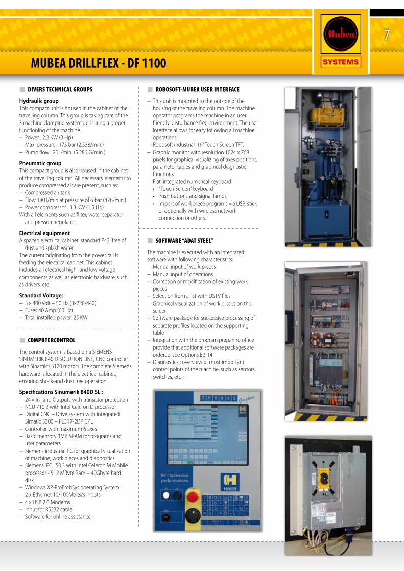
ROBOSOFT-MUBEA USER INTERFACE
− This unit is mounted to the outside of the housing of the traveling column. The machine operator programs the machine in an user friendly, disturbance free environment. The user interface allows for easy following all machine operations.
− Robosoft industrial 19” Touch Screen TFT.− Graphic monitor with resolution 1024 x 768
pixels for graphical visualizing of axes positions, parameter tables and graphical diagnostic functions.
− Flat, integrated numerical keyboard• “TouchScreen”keyboard• Pushbuttonsandsignallamps• ImportofworkpieceprogramsviaUSB-stick
or optionally with wireless network connection or others.
SOFTWARE “ADAT STEEL”
The machine is executed with an integrated software with following characteristics:− Manual input of work pieces− Manual input of operations− Correction or modification of existing work
pieces− Selection from a list with DSTV files− Graphical visualization of work pieces on the
screen − Software package for successive processing of
separate profiles located on the supporting table
− Integration with the program preparing office provide that additional software packages are ordered, see Options E2-14
− Diagnostics : overview of most important control points of the machine, such as sensors, switches, etc…
MUBEA SYSTEMSExport departmentOekensestraat 120B-8800 Rumbeke (Belgium)tel. 00-32-51-26 52 00fax 00-32-51-26 52 [email protected]
DRILLFLEX
MUBEA SYSTEMS MEMBER OF THE
HACO GROUP
CNC PROFILE DRILLING MACHINES
MUBEA DRILLFLEX - DF 1100
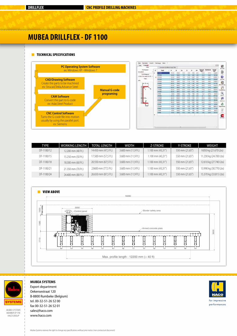
VIEW ABOVE
TECHNICAL SPECIFICATIONS
TYPE WORKING LENGTH TOTAL LENGTH WIDTH Z-STROKE Y-STROKE WEIGHTDF-1100/12 12.200 mm (40 Ft.) 14.450 mm (47,5 Ft.) 3.600 mm (11,9 Ft.) 1.100 mm (43,31”) 550 mm (21,65”) 9.850 kg (21.670 Lbs)
DF-1100/15 15.250 mm (50 Ft.) 17.500 mm (57,5 Ft.) 3.600 mm (11,9 Ft.) 1.100 mm (43,31”) 550 mm (21,65”) 11.230 kg (24.700 Lbs)
DF-1100/18 18.300 mm (60 Ft.) 20.550 mm (67,5 Ft.) 3.600 mm (11,9 Ft.) 1.100 mm (43,31”) 550 mm (21,65”) 12.610 kg (27.740 Lbs)
DF-1100/21 21.350 mm (70 Ft.) 23600 mm (77,5 Ft.) 3.600 mm (11,9 Ft.) 1.100 mm (43,31”) 550 mm (21,65”) 13.990 kg (30.770 Lbs)
DF-1100/24 24.400 mm (80 Ft.) 26.650 mm (87,5 Ft.) 3.600 mm (11,9 Ft.) 1.100 mm (43,31”) 550 mm (21,65”) 15.370 kg (33.815 Lbs)
CNC Control SoftwareTurns the G-code file into motion usually by using the parallel port.
ex: Siemens
PC Operating System Softwareex: Windows XP - Windows 7
CAD/Drawing SoftwareCreate the parts to be machinedex: Strucad,Tekla,Advance Steel
Manual G-code programing
CAM SoftwareConvert the part to G-code
ex: Adat,Steel Product
Mubea Systems reserves the right to change any specifications without prior notice. (non contractual document)