Embed Size (px)
Citation preview

IWCF United Kingdom Branch
Drilling Calculations Distance Learning Programme
Part 2 – Areas and Volumes

IWCF UK Branch Distance Learning Programme - DRILLING CALCULATIONS
Part 2, Introduction 2 of 188
Contents Introduction Training objectives How to use this training programme How the programme is laid out Section 1 Calculating areas Section 2 Calculating volumes Section 3 Oilfield volumes Section 4 Borehole geometry – Surface BOP operations Section 5 Borehole geometry – Subsea BOP operations Section 6 Pump output, strokes, time Section 7 Volume and pump strokes - kill sheet calculations Section 8 Trip monitoring calculations

IWCF UK Branch Distance Learning Programme - DRILLING CALCULATIONS
Part 2, Introduction 3 of 188
Introduction Welcome to the IWCF UK-Branch Drilling Calculations Distance Learning Programme. Nowadays, mathematics is used almost everywhere, at home at leisure and at work. More than ever knowledge of mathematics is essential in the oil industry. The aim of this programme is to introduce basic mathematical skills to people working in or around the oilfield. The programme will lead on to some of the more complex calculations required when working in the industry. By the end of the programme, the user should have acquired the knowledge and skills required prior to taking an IWCF Well Control certification programme.

IWCF UK Branch Distance Learning Programme - DRILLING CALCULATIONS
Part 2, Introduction 4 of 188
Training Objectives When you have completed the package you should: - • Have a good understanding of basic mathematics including;
− Rounding and estimating − The meaning and use of mathematical symbols − The use of the calculator − Fractions and decimals − Ratios and percentages − How to solve equations.
• Have a knowledge of the most common oilfield units and how they are used • Be able to calculate volumes in the appropriate units including
− Square sided tanks − Cylindrical tanks
• Have an understanding of borehole geometry and be able to carry out calculations
regarding the same • Be able to carry out calculations for trip monitoring • Be able to carry out the more common well control calculations including;
− Hydrostatic pressures − Formation pressures
• Understand and list the concepts of kick prevention and recognition • Understand how the circulating system works and carry out calculations regarding the
same. A more detailed set of objectives is stated at the start of each section of the programme.

IWCF UK Branch Distance Learning Programme - DRILLING CALCULATIONS
Part 2, Introduction 5 of 188
How to use this training programme Using the materials This programme is designed as a stand-alone training programme enabling you to work through without external support. No one, however, expects you to work entirely by yourself, there may be times when you need to seek assistance. This might be in the form of a discussion with colleagues or by seeking the help of your supervisor. Should you require guidance, the best person to speak to would normally be your supervisor, failing this contact the Training department within your own company. Planning Whether you plan to use this programme at work or at home, you should organise the time so that it is not wasted. Set yourself targets to reach during a certain time period. Do not try to use the material for 5 minutes here and there, but try to set aside an hour specifically for study. It may even be useful to produce a timetable to study effectively. Week 1 Week 2 Week 3 Week 4 Monday Revise section 3
Revise Section 7
Work through section 8
Tuesday Work through section 1 18:30 – 19:30
Work through section 5
Wednesday Work through sections 4
Thursday
Revise section 5 Work through section 6
Friday Revise section 1 Work through section 2 10:00 – 11:00
Discuss with colleagues and/or supervisor
Saturday
Discuss with colleagues and/or supervisor
Sunday Revise section 2 Work through section 3
Discuss sections 1 to 4 with colleagues and/or supervisor on rig
Revise section 6 Work through section 7

IWCF UK Branch Distance Learning Programme - DRILLING CALCULATIONS
Part 2, Introduction 6 of 188
Organising your study Once you have prepared a study timetable, think about what you have decided to do in each session. There are a few basic guidelines to help you plan each session Do
• Find somewhere suitable to work, for example a desk or table with chair, comfortable lighting and temperature etc.
• Collect all the equipment you may need before you start to study, e.g. scrap paper, pen, calculator, pencil etc.
• Know what you plan to do in each session, whether it is an entire section or a subsection
• Work through all the examples, these give you an explanation using figures. Each section contains “try some yourself …” you should do all these.
• Make notes, either as you work through a section or at the end
• Make notes of anything you wish to ask your colleagues and/or supervisor. Don’t
• Just read through the material. The only way to check whether you have understood is to do the tests.
• Try to rush to get through as much as possible. There is no time limit, you’re only aim should be to meet the training objectives.
• Keep going if you don’t understand anything. Make a note to ask someone as soon as possible.
• Spend the entire session thinking about where to start.
IWCF UK Branch Distance Learning Programme - DRILLING CALCULATIONS
Part 2, Introduction 7 of 188
How the programme is laid out The programme is split into three parts. Each part is further divided into sections covering specific topics. At the start of each section there is information and objectives detailing what are to be covered. Also at the start is an exercise called “Try these first . . . “. These are questions covering the material in the section and are designed for you to see just how much you already know. Do just as it says and try these first! You can check your answers by looking at the end of the section. Answers look like this; Throughout each section you will find worked examples. Following these examples you will find exercises to try yourself. They are shown with a calculator although not questions will require one. Check your answers before carrying on with the sections. If necessary, go back and check the material again.
Try these first . . .Exercise . . .
?
Answers –
Try some yourself -
Examples

IWCF UK Branch Distance Learning Programme - DRILLING CALCULATIONS
Part 2, Introduction 8 of 188
Throughout the section there are boxes with other interesting facts. The “Of interest” boxes are not core material but provide background knowledge.
Of interest / Other facts

IWCF UK Branch Distance Learning Programme – DRILLING CALCULATIONS
Part 2 Section 1 9 of 188
Section 1 Calculating areas In Part One we discussed the concept of area – what we mean by “area”, what we measure using area and the units of measurement we use. In this section we will examine area in more detail and explain how to calculate the area of the more common two-dimensional shapes. We will also look at the different solid shapes and explain how to calculate the surface area of these shapes. On the rig we might need to calculate area to estimate quantities of paint or available deck area. Objectives • To define various shapes and their names. • To examine different ways of estimating area. • To show how to calculate the areas of various shapes. • To discuss the importance of units.

IWCF UK Branch Distance Learning Programme – DRILLING CALCULATIONS
Part 2 Section 1 10 of 188
Try these first . . . Exercise 2.1 1. Calculate the following areas;
a. A square 3 inches by 3 inches. b. A rectangle 5 feet by 4 feet.
c. A triangle 11 inches high with a 4 inch base.
d. A circle with a diameter of 9 inches.
e. A rectangle 4.5 feet by 2.3 feet.
2. Calculate the surface area in square inches of the following cuboid.
Height 6 inches Width 3 inches Length 10 inches Surface area = square inches
3. Calculate the surface area of the following closed cylinder.
Diameter 4 feet
Height 10 feet
Surface area = square inches
?

IWCF UK Branch Distance Learning Programme – DRILLING CALCULATIONS
Part 2 Section 1 11 of 188
Area
Definitions Perimeter is the distance around a flat shape. Area is the amount of flat space inside the perimeter. For example The perimeter of a football pitch The area of the same football pitch Shapes Basic two-dimensional shapes are bound by one or more sides. Some of the more common are shown below. Square Rectangle Circle Ellipse Rhombus Parallelogram Pentagon Hexagon Triangle

IWCF UK Branch Distance Learning Programme – DRILLING CALCULATIONS
Part 2 Section 1 12 of 188
Shapes with curved sides can be circles or ellipses.
Shapes that are bound by straight sides are called polygons. Regular polygons have sides all the same length.
Shapes with three straight sides are triangles. A regular triangle is called an equilateral triangle. The sail on the yacht is an example of a triangle.
Shapes with four sides are quadrilaterals. These include squares and rectangles. An example of a rectangle is a door.
Of interest Shapes with more than 4 sides have special names: -
5-sided polygon = pentagon 6-sided polygon = hexagon
7-sided polygon = heptagon 8-sided polygon = octagon
9-sided polygon = nonagon 10-sided polygon = decagon
12-sided polygon = dodecagon

IWCF UK Branch Distance Learning Programme – DRILLING CALCULATIONS
Part 2 Section 1 13 of 188
Areas of simple shapes
Example Robert is putting a window into his garden shed. He looks at a few different shapes and wonders which would let in most light. The square panes of glass are all the same size. Does this depend on the height alone, the length alone or the number of panes? Which one should he buy? Of course the number of glass panes is the most important – more panes, more light. Counting the number of panes shows number 1 to have the most at 16 panes. The number of square panes gives a measure of the area of glass in each window.
21
3

IWCF UK Branch Distance Learning Programme – DRILLING CALCULATIONS
Part 2 Section 1 14 of 188
One of the simplest ways to calculate the area of a shape is draw a grid and count the number of squares it covers. The areas of figures with straight sides are much easier to find using this method.
Example Count the number of squares in the following shapes. a. Answer : 30 b. Answer : 15 c. Answer : 16 d. Answer : 8
(6 full squares + 4 half squares = 8 squares)

IWCF UK Branch Distance Learning Programme – DRILLING CALCULATIONS
Part 2 Section 1 15 of 188
Try some yourself . . . Exercise 2.2 Find the areas of these shapes by counting the squares.
1.
2.
3.
4.
5.

IWCF UK Branch Distance Learning Programme – DRILLING CALCULATIONS
Part 2 Section 1 16 of 188
Areas of complex shapes Areas of complex shapes can be estimated by dividing the shapes up into simple shapes and working out the areas of those shapes. One way this can be done is by dividing up into squares.
You would then count the number of whole squares covered by each shape, then count the number of part squares covered by each shape, divide this by 2 to get an average number of whole squares, add the two together.
Example Number of squares = 56
Number of whole squares = 41 Number of part squares = 20
Area = Whole squares + part squares 2
= 22041+ squares
= 51 squares

IWCF UK Branch Distance Learning Programme – DRILLING CALCULATIONS
Part 2 Section 1 17 of 188
Try some yourself . . . Exercise 2.3 Estimate the area of each shape by counting the squares.
a) b)
c) d)

IWCF UK Branch Distance Learning Programme – DRILLING CALCULATIONS
Part 2 Section 1 18 of 188
Angles Before we discuss the different shapes, we must touch on the subject of angles. Angles are formed when two straight lines meet each other. An angle can be thought of as the amount of opening between two lines. Imagine opening a door – at first it will only be open slightly and the angle is small, as you open the door wider the angle becomes larger. Door opening
Angle increasing Angles can be though of as a measure of turning. The hands of a clock move through angles as they turn. The minute hand goes around a complete circle in one hour. This complete circle is measured as 360 degrees (abbreviated to 360o).
360o
A half turn is 180o.
A quarter turn is 900.

IWCF UK Branch Distance Learning Programme – DRILLING CALCULATIONS
Part 2 Section 1 19 of 188
This 90o angle is known as a right angle. Note the in the corner denoting a right angle
Angles less than 90o are called acute e.g. 20o, 45o, 65o.
Angles between 90o and 180o are called obtuse e.g. 140o, 110o, 156o.
IWCF UK Branch Distance Learning Programme – DRILLING CALCULATIONS
Part 2 Section 1 20 of 188
Areas of regular shapes Quadrilaterals A quadrilateral has;
- 4 straight sides - 4 angles add up to 360 o
Some have special names, for example square, rectangle. Rectangle
- quadrilateral (shape with 4 straight sides) - all angles are right angles - opposite sides are equal in length to each other - opposite sides are parallel
b
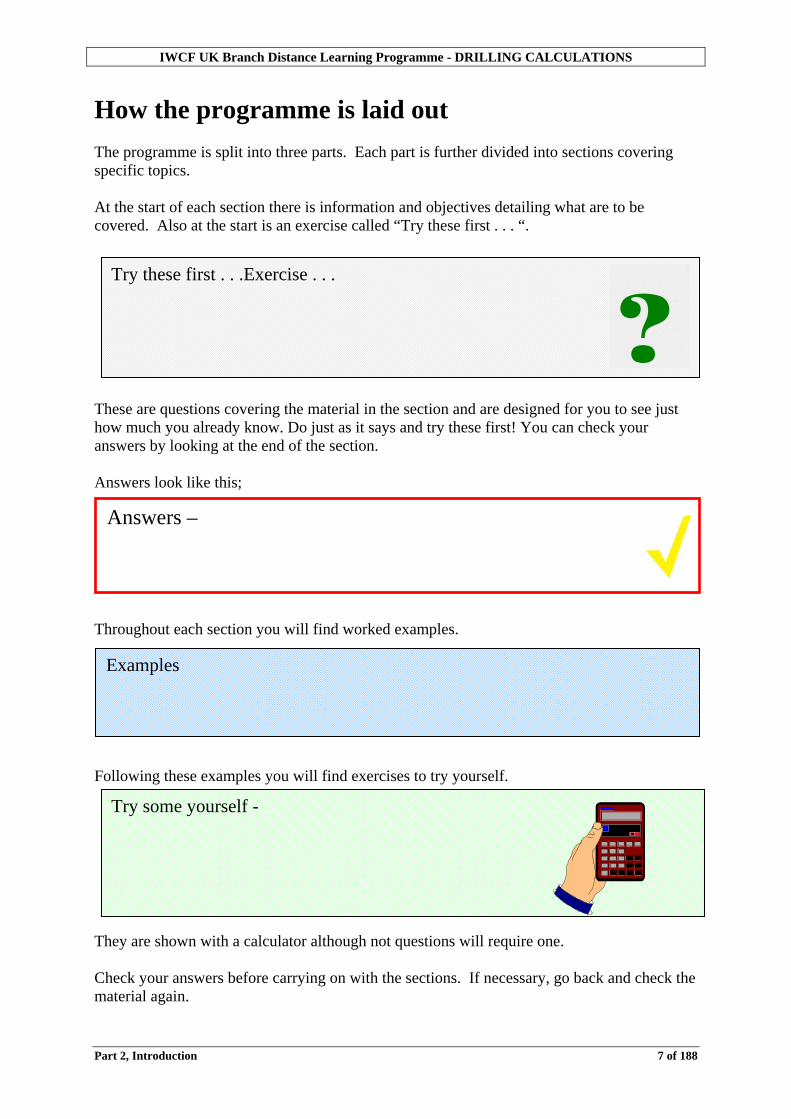
Example Previously to work out the area of the rectangle shown we have counted the squares. (each square represents 1 square inch) The rectangle covers 15 squares, each of area 1 square inch Area of the rectangle = 15 square inches
l
90o
Example How can you find the area of this rectangle without counting all the squares? 3 squares broad (high) 10 squares long This is 3 rows of 10 squares which is 10 x 3 = 30 squares

IWCF UK Branch Distance Learning Programme – DRILLING CALCULATIONS
Part 2 Section 1 21 of 188
Try some yourself . . . Exercise 2.4 Calculate the area of these rectangles in number of squares. a) b) c)
Example It is not necessary to divide the whole area into squares. Find the area of this rectangle. 6 squares 10 squares The rectangle has 10 rows each of 6 squares. Its area is 10 x 6 = 60 squares

IWCF UK Branch Distance Learning Programme – DRILLING CALCULATIONS
Part 2 Section 1 22 of 188
For a rectangle: Area = length x breadth
A = l x b = lb
Example What is the area of this rectangle? It is not necessary to draw in the 1inch squares. It can be seen that the number of squares fitting along the length = 9
the number of squares fitting along the breadth = 3 the number of squares required for the area = 9 x 3 = 27
Area of the rectangle = 27 square inches
9 inches
3 inches
Try some yourself . . . Exercise 2.5 Calculate the area of the following. 1. 2. 3.
4 inches
3 inches
2 inches
11 inches
2 miles
1 mile

IWCF UK Branch Distance Learning Programme – DRILLING CALCULATIONS
Part 2 Section 1 23 of 188
Square A square is really a rectangle with all four sides the same length.
- each angle is a right angle (90o) - 4 sides all the same length
The importance of units When calculating areas, the units must be consistent. It is not possible to calculate areas using measurements in different units.
l
l
Example What is the area of this square? A = 3 x 3 = 32 = 9 square inches
3 inches
3 inches
Example A rectangle measures 9 inches by 2 feet. To calculate the area, we must first make the units compatible. Either convert 9 inches to feet Or convert 2 feet to inches. The area will then be; Inches 9 x 24 = 216 square inches Feet 0.75 x 2 = 1.5 square feet Tip Convert the units of measurement to give the answer in the units you require.

IWCF UK Branch Distance Learning Programme – DRILLING CALCULATIONS
Part 2 Section 1 24 of 188
Areas of rectangles and squares – summary We have worked out the areas of different rectangles and squares (remember, a square is simply a special type of rectangle). We did this by multiplying the length of one side by the length of the other. For a rectangle:
For a square:
Remember the units must be consistent.
length
breadth (width)
length
length
Formula is; Area = length x breadth
Formula is; Area = length2
Try some yourself . . . Exercise 2.6 Calculate the following areas in square feet and also in square inches. 1. 2. 3.
2 feet
1 foot
4 feet 7 inches
3 feet 9 inches
1 foot
1 foot

IWCF UK Branch Distance Learning Programme – DRILLING CALCULATIONS
Part 2 Section 1 25 of 188
Try some yourself . . . Exercise 2.7 1. What are the areas of the following squares? a)
b)
c). 2. Find the areas of the following rectangles, remembering to give the answers with
units.
a) Top of a domino 1inches wide and 2 inches long
b) Floppy disc 3 inches square
c) Envelope 6 inches by 3 inches
d. A table top 3 feet 5 inches by 5 feet.
5 inches
1 foot
4 inches

IWCF UK Branch Distance Learning Programme – DRILLING CALCULATIONS
Part 2 Section 1 26 of 188
Conservation of area Another way to work out areas of complex shapes is to divide them into regular shapes and add up the areas.
Example The square has an area of 100 square inches. Part A must be half (or 50 square inches). Parts B + C must be a quarter each (or 25 square inches). We can now calculate the areas of the following shapes. a. Area = 25 + 25 = 50 sq in b. Area = 50 + 25 = 75 sq in c. Area = 50 + 25 + 25 = 100 sq in
B
C
B
A
C
BA
A
C
A
B
C

IWCF UK Branch Distance Learning Programme – DRILLING CALCULATIONS
Part 2 Section 1 27 of 188
As we can see from the last example, it does not matter how the three parts are arranged, if they are all used the area will be 100 square inches. This is called “Conservation of area”. If a shape is cut up and rearranged, the perimeter may change, the area does not, for example; The easiest way to calculate the area of complex shapes is to divide them up and rearrange into a regular shape.

IWCF UK Branch Distance Learning Programme – DRILLING CALCULATIONS
Part 2 Section 1 28 of 188
Try some yourself . . . Exercise 2.8 The square has an area of 36 square inches. What are the areas of the following? a) b) c)

IWCF UK Branch Distance Learning Programme – DRILLING CALCULATIONS
Part 2 Section 1 29 of 188
Areas of more complicated shapes
Example This L-shaped corridor is to have a replacement carpet but first you need to work out the area in order to calculate the cost of a new carpet.
It can be divided into two rectangles to make calculation easier.
a) What is the length of x, in feet? b) What is the area of each rectangle? c) What is the total area of the corridor?
a) 20 - 2 = 18 feet
b) 2 x 8 = 16 sq ft
18 x 2 = 36 sq ft
c) 16 + 36 = 52 sq ft
20 feet
8 feet
2 feet
2 feet
x feet

IWCF UK Branch Distance Learning Programme – DRILLING CALCULATIONS
Part 2 Section 1 30 of 188
Example A lawn is 6 ft by 3 ft and has a 1 ft path running all the way round. Find the area of the path. Total area = length x breadth of outer rectangle = 8 x 5 = 40ft2 Area of grass in central rectangle = 6 x 3 = 18 ft2 Area of path = 40 – 18 = 22ft2
3 ft
1 ft
6 ft
Example Find the area of this shape. The shape could be divided into 3 rectangles in two different ways. In this case however, it would be easier to subtract areas. We can look at the shape as a large rectangle (A) with a small square (B) taken out. Area of large rectangle A = 6 x 4 = 24 in2 Area of small square B = 2 x 2 = 4 in2 Area of shape = Area A – Area B = (24 – 4) in2 = 22 in2
4 in
2 in
6 in
2 in
2 in
4 in
6 in A
2 in
2 in
B

IWCF UK Branch Distance Learning Programme – DRILLING CALCULATIONS
Part 2 Section 1 31 of 188
Try some yourself . . . Exercise 2.9
1. Calculate the area of a rectangle with the following dimensions:
a. 12 in x 5 in b. 22 ½ in x 4 in c. 3 ft x 10 ft d. 2ft x 8 ft
2. Calculate the areas of the following shapes
a.
b. c. 3. A square has a perimeter of 22 inches. What is its area? 4. How many square inches are there in an area of 6 square feet? 5. A room is 15 feet by 12 feet. What would be the cost of the carpet
a. for 50% wool? b. for 80% wool?
4 in
4 in
8 in1 ft
2 ft 6 in
2 in 2 in
2 in
1 in
1 in
3 in 6 in
50% Wool - £9.99 per yd2 80% Wool - £18.75 per yd2
14 in
6 in
6 in
4 in

IWCF UK Branch Distance Learning Programme – DRILLING CALCULATIONS
Part 2 Section 1 32 of 188
Triangles Triangles have;
- three straight sides - three angles add up to180 o
If you think of a triangle as half a rectangle, the area of a triangle is half the area of a rectangle with the same height and base. This can be seen easily with a right-angled triangle.
It works for any triangle; The formula for the area of a triangle
Area = heightbase×21
base
height
base
height
Of interest Different types of triangles have different names;
Right angled triangle - 1 angle of 90 o - longest side opposite this called hypotenuse
Equilateral triangle
- 3 equal angles - 3 equal length sides
Isosceles triangle
- 2 equal angles - 2 equal sides opposite the equal angles
Scalene triangle
- 3 different sides - 3 different angles
90o

IWCF UK Branch Distance Learning Programme – DRILLING CALCULATIONS
Part 2 Section 1 33 of 188
Example Calculate the area of the triangle
A = heightbase×21
= 51221
×
= 30 square inches
13 in
12 in
5 in
Example Find the area of the following;
Area = heightbase×21
= 5821
×
= 20 square feet
Area = heightbase×21
= 7.1221
×
= 1.7 square inches
8 ft
5 ft
2 inches
1.7 inches

IWCF UK Branch Distance Learning Programme – DRILLING CALCULATIONS
Part 2 Section 1 34 of 188
Try some yourself . . . Exercise 2.10 1. Calculate the areas of the following triangles.
a) b) c)
2. Calculate the area of each sail.
Small sail; Larger sail; height 20 feet height 20 feet base 10 feet base 15 feet
6 inches
12 inches
10 inches
3 inches
4 inches
8 inches

IWCF UK Branch Distance Learning Programme – DRILLING CALCULATIONS
Part 2 Section 1 35 of 188
Try some yourself . . . Exercise 2.10 continued 3. What area has to be painted below the stairs?
13 feet
17 feet

IWCF UK Branch Distance Learning Programme – DRILLING CALCULATIONS
Part 2 Section 1 36 of 188
Other quadrilaterals
Parallelogram
- 2 pairs of parallel sides - opposite sides of equal length
The area of a parallelogram is the same as a rectangle. This can be shown using conservation of area where the shape is divided up and moved around until a rectangle has been formed.
Another way of finding the area of a parallelogram is to divide it up into 2 triangles. The area of the parallelogram; Area = 2 x area of one triangle
= heightbase×××212
= base x height
Example Calculate the area of the parallelogram.
Area = base x height = 10 x 8 = 80 square inches
10 inches
8 inches
Definition of parallel lines Parallel lines are the same distance apart from each other all the way along their length. They will never meet even if they are made longer.

IWCF UK Branch Distance Learning Programme – DRILLING CALCULATIONS
Part 2 Section 1 37 of 188
Try some yourself . . . Exercise 2.11 Calculate the areas of the following parallelograms. 1. 2. 3.
4 ft
3 ft
6 in
2 in
20 ft
2 ft

IWCF UK Branch Distance Learning Programme – DRILLING CALCULATIONS
Part 2 Section 1 38 of 188
Trapezium - pair of parallel sides - Area = average length of parallel sides x distance between them
A trapezium can be rearranged to form a rectangle.
The area of a trapezium
Area = heightlar perpendicusides parallel of sum21
××
= )( hba +21
Example Find the area of the trapezium shown
Area = )( hba +21
Area = )( 34221
×+
= 3 x 3 in2 = 9 in2
2 in
4 in
3 in
b
a
h
Try some yourself . . .Exercise 2.12 Calculate the areas of the following trapeziums 1. 2. 3.
6 in
1 in
1 in
3 ft
2 ft
6 ft
20 ft
9 ft
2 ft

IWCF UK Branch Distance Learning Programme – DRILLING CALCULATIONS
Part 2 Section 1 39 of 188
Circles
- complete turn in a circle is measured as 360o - distinct terminology
The perimeter of a circle is called the Circumference. The circumference is given the letter c in formulae.
Radius is the distance from the centre of a circle to its circumference. All radii (plural) of the same circle are the same length. The radius is given the letter r in formulae.
Diameter (d) is a straight line drawn through the centre of a circle to divide it into 2 halves. The diameter is twice the length of the radius. The diameter is given the letter d in formulae.
If you take a piece of cotton and measure the length of the circumference, then take another piece of cotton and measure the diameter, you find that the circumference is always approximately three times the length of the diameter. The accurate measurement is actually 3.141592654 to nine decimal places. This is called “pi” or “π” which is the Greek letter for p. This relationship between the circumference and the diameter is always the same. The circumference can thus be calculated from the diameter or radius. Circumference = π x diameter c = πd or
Circumference = 2 x π x radius
c = 2πr π is usually approximated to perform calculations. In this programme we will use 3.142

IWCF UK Branch Distance Learning Programme – DRILLING CALCULATIONS
Part 2 Section 1 40 of 188
Area of a circle The area of a circle can be thought of in many ways. For example, if a circle is cut into equal slices (sectors) and arranged alternately as shown the area is unchanged.
If the sectors are small enough then the shape will be;
radius (r) half of circumference (c)
The height of the rectangle will be r (the radius of the circle), and the length will be half the circumference (c).
Area = radius 2
ncecircumfere×
Area = rc×
2
Substitute rπ2 for c ( rc π2= )
= rr×
22π
Cancel out 2’s = rr ×π = πr2 Another way to look at the area of a circle is to imagine a piece of rope wound into a spiral over the circle. If the rope is cut along the radius and the pieces straightened out, they form a rough triangle, The height of a triangle is r (radius) and the base is 2πr.
Area = rr ×× π221
= πr2
r
2πr

IWCF UK Branch Distance Learning Programme – DRILLING CALCULATIONS
Part 2 Section 1 41 of 188
Formulae for the area of a circle The area of a circle can be calculated using; Area = 2rπ Or because diameter = radius2×
Area = 4
2dπ
Where π = pi = 3.142 (approximated) r = radius d = diameter In the above formula, two of the numbers are CONSTANTS, that is they do not change.
π is always 3.142 4 is always 4
So with the formula written like this Area = 2
4d×
π
We could divide π by 4 to give a single constant instead of two separate ones.
785.04
=π
So the formula then becomes Area of a circle = 0.785 x diameter2
Example Sometimes you are given the diameter instead of the radius. The diameter is twice the radius. Find the area of a circle with a diameter of 15 in Radius = diameter = 15 = 7.5 in
2 2 Area = πr2 = 3.142 x 7.52 = 3.142 x 56.25 = 176.7375 in2
15 in

IWCF UK Branch Distance Learning Programme – DRILLING CALCULATIONS
Part 2 Section 1 42 of 188
Example Calculate the area of the circle radius 10 inches Area = 2rπ = 210142.3 × = 314.2 square inches
10 inches
Example Calculate the area of the circle diameter 3 feet
Area = 4
2dπ
= 43142.3
2
×
= 7.07 square feet
3 feet
Example A hot tub has a diameter of 10 feet. What is the area it covers? Area = 0.785 x d2
= 0.785 x 102
= 78.55 square feet

IWCF UK Branch Distance Learning Programme – DRILLING CALCULATIONS
Part 2 Section 1 43 of 188
Try some yourself . . . Exercise 2.13 1. Calculate the areas of the following circles
a. radius = 9 inches b. radius = 2 inches
c. diameter = 8 feet d. diameter = 5 inches
e. diameter = 20 inches
2. A dinner plate has a diameter of 10 inches. What is the area?
3. A green on a golf course has a diameter of 30 feet.
What is the surface area of the green?

IWCF UK Branch Distance Learning Programme – DRILLING CALCULATIONS
Part 2 Section 1 44 of 188
Summary of area formulae Rectangle Area = length x breadth Square Area = 2length Triangle Area = heightbase
21
×
Parallelogram Area = heightbase× Trapezium Area = )( heightsides long&short of sum
21
××
Circle 1. Area = 2rπ
2. Area = 4
2dπ
3. Area = 0.785d2
r = radius d = diameter π = 3.142 Reminder: Units must be constant

IWCF UK Branch Distance Learning Programme – DRILLING CALCULATIONS
Part 2 Section 1 45 of 188
Rearranging formulae Rearranging formulae If you are given the area of a shape but need to know the height or length it is useful to be able to rearrange the formula for area.
Example – Constant units Find the area of a garden whose sides measure 24 ft 9 inches by 48 ft 10 inches. Area of a rectangle = length x breadth To calculate this you need to convert the measurement to inches 24 ft 9 in = 297 inches or 24.75 48 ft 10 in = 586 inches or 48.83
Area = 297 x 586 or 24.75 x 48.83 = 174,042 in2 or 1208.5425 ft2 For a garden the most appropriate would be 1208 ft2 (to the nearest square foot).
Example Find the breadth (or width) of this rectangle Rearrange the formula for the area of a rectangle;
Area = BreadthLength×
Remember – a formula can be rearranged so long as the same is done to both sides.
LengthBreadthLength
LengthArea ×
=
Cancel out length
BreadthLengthArea
=
or
LengthArea Breadth =
= 6
12
= 2 in
Area = 12 in2
6 in
? in

IWCF UK Branch Distance Learning Programme – DRILLING CALCULATIONS
Part 2 Section 1 46 of 188
Example Find the height of this triangle
Area of triangle = heightbase21
××
Height = basearea2×
= 7562×
= 16 in
Try some yourself . . . Exercise 2.14 1. Find the breadth (or height) of the following;
a. Square: area = 144 square inches b. Rectangle: area = 160 square inches
length =8 inches
c. Triangle: area = 100 square inches base = 10 inches
7 in
Area = 56 in2

IWCF UK Branch Distance Learning Programme – DRILLING CALCULATIONS
Part 2 Section 1 47 of 188
Solid shapes Solid figures are shapes that take up space in all directions unlike flat shapes like squares and circles. The following are some solid shapes; Sphere A ball bearing, tennis ball or golf ball are examples of spheres. Cube A lump of sugar is sometimes called a “sugar cube”.
It has six faces, eight corners and twelve edges. All the edges are the same length. All the faces are equal size squares.
A cuboid has 3 pairs of unequal sized faces. Prism A prism has the same shape all the way along its length. They are usually named by the shape of the ends.
Triangular prism The end is a triangle.
Square or rectangular prism The end is a square or rectangle. Another name for this is a cuboid (that is similar to a cube but with unequal size faces). Circular prism The end is a circle. Also known as a cylinder. Most food tins are cylinders.
Hexagonal prism The end is a hexagon.
A pencil is often a hexagonal prism.

IWCF UK Branch Distance Learning Programme – DRILLING CALCULATIONS
Part 2 Section 1 48 of 188
Irregular prism An irregular prism has a face which is not a well known shape. Cross section As the shape of a prism is the same all the way along its length, any slice at a right angle through the prism will be the same shape as the end. This shape is known as the cross section. Surface area of a solid Surface areas of solids are calculated by finding the area of each individual face in exactly the same way as the area for a 2-dimensional shape. Surface area of a cuboid Imagine the following shape It has 2 sides
2 ends

IWCF UK Branch Distance Learning Programme – DRILLING CALCULATIONS
Part 2 Section 1 49 of 188
A top and a bottom
The surface area would be the same as all the area of all the faces. Another way to picture surface area is to open out the shape as though it were made of card. It is easy to see that the surface area is the sum of all the faces that make up the shape.
SIDE
SIDE
BOTTOM
TOP
END
END

IWCF UK Branch Distance Learning Programme – DRILLING CALCULATIONS
Part 2 Section 1 50 of 188
Example What is the surface area of the walls and ceiling of the following room? (Ignore doors and windows.)
Walls Two 10 feet long walls Area of one wall = 10 x 8 = 80 sq ft Area of two walls = 80 x 2 = 160 sq ft Two 15 feet long walls Area of one wall = 15 x 8 = 120 sq ft Area of two walls = 2 x 120 = 240 sq ft Ceiling Area of ceiling = 10 x 15 = 150 sq ft Total area = 550 sq ft If one litre of emulsion paint covers 50 square feet, how many litres are required for one coat? litres 1150550 =÷
Example What is the surface area of a cuboid of the following dimensions? Surface area = (area top + area bottom) + area two sides + area two ends = (12 x 2 + 12 x 2) + 2(12 x 5) + 2(2 x 5) = (24 + 24) + 120 + 20 = 188 in2
length = 12 inches
height = 5 inches
width = 2 inches
8 feet
15 feet 10 feet

IWCF UK Branch Distance Learning Programme – DRILLING CALCULATIONS
Part 2 Section 1 51 of 188
Try some yourself . . . Exercise 2.15 A room has the following dimensions,
a) Calculate the surface area of the walls and ceiling (ignore doors and windows).
(answer to 1 decimal place) Area = square feet
b) If the paint chosen covers 80 square feet per litre, how many litres are required? (answer to 1 decimal place).
(i) One coat litres
(ii) Two coats litres
11 feet 10 feet
8 feet

IWCF UK Branch Distance Learning Programme – DRILLING CALCULATIONS
Part 2 Section 1 52 of 188
Surface area of a cylinder How do we calculate the surface area of the cylinder (e.g. a tin of baked beans).
Diameter = 3 inches Height = 4 inches
Imagine the cylinder made of card and opened out until flat.
We now have two circles of 3” diameter and a rectangle.
The short sides of the rectangle would be the height of the tin (4 in). The long side of the rectangle would be the same as the circumference of the end circles. This would be; Circumference = dπ (d = diameter) = 3.142 x 3 inches = 9.43 inches Now we have all the dimensions we need to calculate the area.
Height
3 in
3 in
4 in 9.43 in
BEANS

IWCF UK Branch Distance Learning Programme – DRILLING CALCULATIONS
Part 2 Section 1 53 of 188
Area of the rectangle = 4 x 9.43 = 37.72 square inches
Area of one circle = 4
2d×π or 0.785d2
= 43142.3
2
× = 0.785d2
= 7.07 square inches = 7.07 in2
Total surface area = 37.72 + 7.07 + 7.07
51.86 square inches
Try some yourself . . . Exercise 2.16 The dimensions of a covered cylindrical tank are; Height = 5 feet Diameter = 10 feet
Calculate the surface area of the tank in square feet.

Section 2 Calculating Volumes In Section one you learned how to calculate areas both two-dimensional and solid three-dimensional shapes. We will now take this a step further and explain how to calculate volumes and capacities of the more common solid shapes. Volume and capacity calculations are essential to the oilfield – we need to know the size of a mud tank, or the volume of mud in the hole amongst many others. Objectives • To define volume and capacity. • To show how to calculate the volumes of various solid shapes. • To explain how to calculate the capacity of a tank in cubic feet. • To discuss the importance of internal and external dimensions of tanks or pipes.
Try these first . . . Exercise 2.17
1. Calculate the following volumes;
a. Cuboid 7 inches long, 4 inches high, 3 inches deep b. Circular prism 2 feet diameter, 7 feet long
(To nearest cubic foot)
2. The internal dimensions of your slug pit is 4 feet by 4 feet and 10 feet deep. Calculate the capacity in cubic feet.
3. Your trip tank is 5 ft 6 in inside diameter and 15 ft in height. Calculate its capacity in cubic feet.
?

IWCF UK Branch Distance Learning Programme – DRILLING CALCULATIONS
Part 2 Section 2 55 of 188
Volume Volume is the space taken up by a solid object, for example a ball bearing or a brick. Volume is measured in cubic units e.g. cubic feet, cubic inches, cubic metres. Capacity Capacity is the internal volume or amount of volume inside a container, for example a bottle, a box or a mud pit (e.g. trip tank). Capacity can be measured in the same units as volume, or in liquid volumes such as gallons or barrels.

IWCF UK Branch Distance Learning Programme – DRILLING CALCULATIONS
Part 2 Section 2 56 of 188
Calculating volumes Volume is the amount of space taken up by a solid object. Capacity is the amount of space inside a solid object i.e. how much it will hold. For example you would need to find the volume of your new fridge freezer to find out whether it will fit into the space in your kitchen. You would need to know the capacity to find out how much food you could store inside it. The two are not the same.
Example
This cube is 1 by 1 by 1. Its volume is 1 cube
The large cube is 3 cubes long, 3 cubes wide and 3 cubes high. Each layer would have 3 rows of cubes with 3 cubes in each row.
Each layer = 9 cubes. 3 layers = 27 cubes
The volume of this cube is 27 cubes

IWCF UK Branch Distance Learning Programme – DRILLING CALCULATIONS
Part 2 Section 2 57 of 188
Volume of cuboids Remember A cuboid is a rectangular box shape. It has six faces which are all rectangles. Opposite faces are the same. Everyday examples include; A brick A box A mud pit A cube is a particular type of cuboid which has faces which are all square and all the same size. Example
This cube is 1 inch long, 1 inch wide and 1 inch high. Its volume is 1 cubic inch or 1 in3 or 1 cu.in. This cuboid is 4 inches long, 3 inches wide and 3 inches high. It could be built up from 1 inch cubes. Each layer would have 3 rows of cubes with 4 cubes in each row. Each layer = 12 cubes. 3 layers = 36 cubes The volume of this cube is 36 in3
The volume of any cube or cuboid = length x breadth (width) x height = l x b x h = lbh

IWCF UK Branch Distance Learning Programme – DRILLING CALCULATIONS
Part 2 Section 2 58 of 188
Tank volumes The formulae for volume of cuboids are used on the rig for square sided tanks.
Example The inside measurements of your slug pit are 5 feet long, 4 feet wide and 8 feet deep. What is the internal volume (or capacity) in cubic feet? Volume = length x width x height = 5 x 4 x 8 = 160 cubic feet
Try some yourself . . . Exercise 2.18 Calculate the following tank volumes in cubic feet.
1. Length 10 ft Width 10 ft Depth 8 ft
2. Length 12 ft
Width 6 ft Depth 10 ft
3. Fill in the gaps: -
Length
(ft) Width
(ft) Depth
(ft) Volume (cu.ft.)
a. 9 7 6 b. 15 10 1200 c. 12 8 1152
length
height
width
IWCF UK Branch Distance Learning Programme – DRILLING CALCULATIONS
Part 2 Section 2 59 of 188
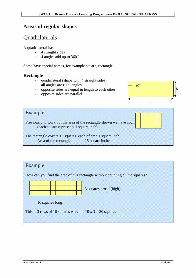
Volume of prisms Remember A prism is a solid which has the same shape all the way along its length (i.e. it has a constant cross section). Common prisms include
Circular prism or cylinder Rectangular prism
Another name for a box shape or cuboid.
Triangular prism
Hexagonal prism
For example a pencil.

IWCF UK Branch Distance Learning Programme – DRILLING CALCULATIONS
Part 2 Section 2 60 of 188
It can be shown that;
Volume of a prism = area of cross section x height The most commonly required calculation is for the volume of a cylinder.
Volume of a cylinder = area of circle x height
= hd×
4
2
π
Or using 0.785 as a constant Volume of a cylinder = 0.785 x h2
Example Your trip tank is 10 feet in height and five feet in diameter. What is the volume in cubic feet?
Volume = hd×
4
2
π
= 1045142.3
2
××
= 196.4 cubic feet
Example A food tin is 4 inches high and 3 inches in diameter. What is the volume in cubic inches?
Volume = 0.785d2 x h
= 0.785 x 32 x 4 = 28.26 cubic inches

IWCF UK Branch Distance Learning Programme – DRILLING CALCULATIONS
Part 2 Section 2 61 of 188
On the rig we need to be able to calculate volumes or capacities of cylinders when we calculate the capacity of a trip tank, or the volume of mud in the hole and the displacement and capacity of pipe. (These terms will be discussed in later sections). It is important at this stage to clarify the difference between outside diameter and inside diameter.
Try some yourself . . . Exercise 2.19 1. Calculate the following tank volumes in cubic feet.
a) height = 12 feet internal diameter = 6 feet
volume = cubic feet
b) height = 15 feet internal diameter = 4 feet
volume = cubic feet

IWCF UK Branch Distance Learning Programme – DRILLING CALCULATIONS
Part 2 Section 2 62 of 188
Example The outside measurements of a steel tank are 3 feet across, 4 feet long and two feet deep. What would be the total volume of space that it takes up? Volume = Length x Breadth x Depth = 4 x 3 x 2 = 24 cubic feet It is made of steel which is 0.1 feet thick (1.2 inches). What is the internal capacity?
The inside measurements are: Breadth = 2.8 feet Length = 3.8 feet Depth = 1.9 feet Internal volume = Length x Breadth x Depth = 3.8 x 2.8 x 1.9 = 20.2 cubic feet (to 1 decimal place) So the capacity of the tank is only 20.2 cubic feet. The volume was calculated using the outside dimensions, whilst the capacity was calculated using the internal dimensions.

IWCF UK Branch Distance Learning Programme – DRILLING CALCULATIONS
Part 2 Section 2 63 of 188
Dimensions of a pipe Another example of when the difference between outside and internal dimensions is when we look at pipes (e.g. drill pipe, drill collars or casing).
An 8 inch drill collar has an outside diameter of 8 inches. The inside diameter might only be 3 inches. When working out volumes and capacities we need to be careful to use the correct dimensions. This will be dealt with fully in later sections.

IWCF UK Branch Distance Learning Programme – DRILLING CALCULATIONS
Part 2 Section 3 64 of 188
This page is deliberately blank

IWCF UK Branch Distance Learning Programme – DRILLING CALCULATIONS
Part 2 Section 3 65 of 188
Section 3 Oilfield volumes When we calculated volumes and capacities in Section two we used cubic units. In this section we will first discuss the units we use to calculate volumes and capacities in the oilfield. We will explain how to calculate volumes and capacities in oilfield volumes. This will include calculating volumes and capacities of tanks, pipes and annulus. Finally we will demonstrate the use of the most common oilfield formulae for calculating volumes and capacities. Objectives • To discuss how volume calculations are used in the oil industry. • To show how to calculate the volumes of;
− square sided tanks − cylindrical tanks − pipe − annulus
• To show how to calculate pipe capacities in bbl/ft • To show how to calculate annular capacities in bbl/ft • To introduce the standard oilfield formulae used for volume calculations.

IWCF UK Branch Distance Learning Programme – DRILLING CALCULATIONS
Part 2 Section 3 66 of 188
Try these first . . . Exercise 2.20
1. The internal measurements of a mud pit are 10 feet long, 9 feet wide, 8 feet deep. Calculate;
a. Its volume in bbl. b. Its capacity in bbl/ft
2. A trip tank is 15 feet high and has an internal diameter of 4 feet.
Calculate;
a. Its volume in barrels. b. Its capacity in bbl/ft
3. Calculate the following pipe capacities in bbl/ft;
a. 5 inch OD 4 inch ID b. 95/8 inch OD 8.68 inch ID
c. 91/2 inch OD 3 inch ID
4. Calculate the following annular capacities in bbl/ft;
a. 8 inch drill collar in 121/4 inch hole
b. 5 inch drill pipe in 81/2 inch hole
c. 5 inch drill pipe in 133/8 inch hole (ID 12.4 inch)
?

IWCF UK Branch Distance Learning Programme – DRILLING CALCULATIONS
Part 2 Section 3 67 of 188
Volumes in the oilfield Remember Volume is the total space that something takes up. Capacity is the amount (volume) that something will hold, or its internal volume.
We usually use cubic feet, gallons or barrels to measure volumes. Capacities are measured in the same units and also in the oilfield in barrels per foot. These will be explained later in this section. Units used on the rig We measure:
- dimensions of a square tank in feet - pipe lengths in feet - pipe diameters in inches - hole diameters in inches
We require:
- volumes in barrels In order to do this we must convert the units.
Example A mud pit has an internal volume of 400 barrels. Its capacity is 400 bbl. When half full, the volume of mud in the pit is 200 bbl. So although the capacity of the pit is 400 bbl, the volume of mud is only 200 bbl.

IWCF UK Branch Distance Learning Programme – DRILLING CALCULATIONS
Part 2 Section 3 68 of 188
Volume of a square sided tank Measure the dimensions (feet)
Length Breadth/Width Height/Depth
Calculate the volume (cubic feet) l x b x h = cubic feet Convert to barrels
Cubic feet x 0.1781 = bbl
lh
b
Example Internal dimensions of the tank Length = 15 feet
Width = 10 feet Depth = 8 feet
1. Calculate the internal volume in cubic feet
Volume = 15 x 10 x 8 = 1,200 cubic feet
2. Convert to barrels To convert from cubic feet into barrels, we must multiply by 0.1781 (or divide by 5.6146) 1,200 cubic feet x 0.1781 = 213.72 barrels
Capacity of the tank to the nearest barrel = 214 barrels

IWCF UK Branch Distance Learning Programme – DRILLING CALCULATIONS
Part 2 Section 3 69 of 188
Volume of a cylinder Measure the dimensions (feet) Internal diameter Height Calculate the volume (cubic feet) 0.785d2 x h = cubic feet Convert to barrels cubic feet x 0.1781 = barrels The capacity is the answer in barrels.
d
h
Example Your trip tank is 15 feet high and 4 feet in diameter. Calculate its capacity in barrels. 1. Volume in cubic feet
= 0.785 x d2 x h = 0.785 x 42 x 15 = 188.4 cubic feet
2. Convert to barrels
188.4 x 0.1781 = 33.55 barrels Capacity of the tank to the nearest barrel = 34 barrels

IWCF UK Branch Distance Learning Programme – DRILLING CALCULATIONS
Part 2 Section 3 70 of 188
The above calculation could be used to calculate the volume of mud inside a pipe or the capacity inside a pipe.
Example
If a pipe has an outside diameter of 2 feet and is made of steel 0.1 feet thick (1.2 inches), its internal diameter will be;
2 – (0.1 x 2) =
2 – 0.2 = 1.8 feet
What would be the capacity in barrels of 5 feet of pipe?
1. Volume in cubic feet
= 0.785 x d2 x h = 0.785 x 1.82 x 5 = 12.72 cubic feet
2. Convert to barrels
= 12.72 x 0.1781 = 2.265 bbl Capacity of the pipe to the nearest 0.1 of a barrel = 2.3 barrels

IWCF UK Branch Distance Learning Programme – DRILLING CALCULATIONS
Part 2 Section 3 71 of 188
Annular Volume Definition of annulus If you place a pipe inside another pipe there is a space between them. This is called an annulus. In the oilfield we often have to calculate annular capacities and volumes (e.g. pipe in hole, pipe in casing).
Annulus

IWCF UK Branch Distance Learning Programme – DRILLING CALCULATIONS
Part 2 Section 3 72 of 188
Calculation of annular capacity Calculate the volume of the large cylinder and subtract the volume of the small cylinder.
Example A circular hole is dug 2 feet in diameter and 3 feet deep. Inside this a post of 1 foot diameter will be concreted in place. How much concrete is required? 1. Work out the volume of the empty hole
Volume = 0.785 x d2 x h = 0.785 x 22 x 3
= 9.42 cubic feet 2. Take away the volume of 3 feet of the post.
Volume = 0.785 x d2 x h
= 0.785 x 12 x 3 = 2.355 cubic feet
3. Calculate the volume of the concrete required (as drawing 1) Volume of concrete = 9.42 – 2.355 = 7.07 cubic feet Convert to barrels = 7.07 x 0.1781 = 1.26 bbl

IWCF UK Branch Distance Learning Programme – DRILLING CALCULATIONS
Part 2 Section 3 73 of 188
Try some yourself . . . Exercise 2.21 A hole is 3 feet in diameter and 10 feet deep. Inside the hole is pipe which has an outside diameter of 2 feet. 1. What is the total capacity of the annulus?
a. In cubic feet b. In barrels
2. What would be the volume of mud in the annulus if the hole was 200 feet deep and the casing 200 feet long?
Annular volume = bbl

IWCF UK Branch Distance Learning Programme – DRILLING CALCULATIONS
Part 2 Section 3 74 of 188
Mud pits Because pipe lengths and depths of mud in a mud pit change constantly, it is more convenient to calculate pipe capacities or tank capacities for each foot. This lets us easily work out how much mud is in the pit if we know the depth of mud.
Example A mud pit has a total capacity of 400 bbl and is 10
feet deep. Calculate the volume of mud in each foot. Volume per foot = Depth capacity Total ÷ = 10 400 ÷ = 40 bbl So each foot of mud in the tank is 40 bbl of mud or the capacity is 40 barrels per foot (bbl/ft). Capacity (bbl/ft) = Depth(ft) (bbl) Volume ÷ Now if we know the depth of mud in the pit we can easily work out the volume of mud. For example, if there is three feet of mud in the pit; 3 feet of mud = 3 x 40 = 120 bbl
400 bbl

IWCF UK Branch Distance Learning Programme – DRILLING CALCULATIONS
Part 2 Section 3 75 of 188
Example A mud pit is 10.5 feet long, 8.5 feet wide and 8 feet deep. Calculate the total capacity in barrels and the capacity in bbl/ft.
1. Calculate the volume in cubic feet. 10.5 x 8.5 x 8 = 714 cubic feet
2. Convert to barrels. 714 x 0.1781 = 127.16 bbl = 127 bbl (to the nearest barrel)
3. Calculate bbl/ft. 8127 ÷ = 15.875 bbl/ft
= 15.9 bbl/ft (to 1 decimal place) How much mud is in the pit given the following depths of mud? a) 3 feet deep
15.9 x 3 = 47.7 bbl b) 7 feet deep
15.9 x 7 = 111.3 bbl

IWCF UK Branch Distance Learning Programme – DRILLING CALCULATIONS
Part 2 Section 3 76 of 188
Try some yourself . . . Exercise 2.22 1. Pit number 2 is 10 feet by 10 feet by 20 feet deep.
a. What is the total capacity of pit number 2 in barrels? b. What is the capacity in bbl/ft?
There is 12 feet of mud in the pit. c. How much mud is in pit number 2 in barrels?
Over two hours of drilling, the level of the pit dropped 5 feet. d. What is the new pit volume in the pit? Derek the derrickman puts 178 barrels of new mud into pit 2. e. What is the new mud level in pit 2? 2. Pit number 4 is a slug pit 4 feet x 3 feet x 20 feet deep. A 32 barrel slug is pumped
down hole.
How much did the mud level drop in pit number 4?
3. Mud pit 3 is 12 feet by 8 feet and is 20 feet deep.
While steady drilling Derek the derrickman measured the level of the mud in the pit as 9 feet.
The mud pumps are stopped for a connection and all the mud in the surface lines drain into pit 3. Derek measures the new pit level is 11 feet.
a. What volume in barrels was initially in pit 3? b. What is the new mud volume in pit 3? c. What volume of mud was in the surface lines?

IWCF UK Branch Distance Learning Programme – DRILLING CALCULATIONS
Part 2 Section 3 77 of 188
Capacity of cylinder in bbl/ft A trip tank holds 40 bbl and is 16 feet deep. If there is one foot of mud in the tank, how many barrels is this? Calculate the volume in one foot Volume per foot = Depth volumeTotal ÷
= 1640 ÷ = 2.5 bbl
So each foot of mud in the tank is 2.5 bbl or the capacity is 2.5 bbl/ft. Again, now we have the capacity in bbl/ft, we can work out the mud volume for any depth. E.g. 3 feet of mud
3 feet x 2.5 bbl/ft = 7.5 bbl
1 ft
Example A trip tank is 15 feet deep and has an internal diameter of 5 feet. Calculate the total capacity in barrels and the capacity in bbl/ft. 1. Calculate the volume in cubic feet.
Volume = 0.785 x d2 x h = 0.785 x 52 x 15 = 294.37 cubic feet
2. Convert to barrels 294.37 x 0.1781 = 52.43 bbl = 52.4 bbl (to 1 decimal place)
3. Capacity in bbl/ft 154.52 ÷ = 3.5 bbl/ft
How many barrels of mud in the tank if the level is; a) 4 feet deep
Volume of mud = Capacity (bbl/ft) x Depth (ft) = 3.5 x 4 = 14 bbl
b) 9 feet deep
Volume of mud = Capacity (bbl/ft) x Depth (ft) = 3.5 x 9 = 31.5 bbl

IWCF UK Branch Distance Learning Programme – DRILLING CALCULATIONS
Part 2 Section 3 78 of 188
Try some yourself . . . Exercise 2.23 If a trip tank is 12 feet deep and 4 feet internal diameter, calculate; 1. Total capacity in barrels. 2. Capacity in bbl/ft 3. Volume of mud in the tank for the following depths of mud;
a. 2 feet b. 3 feet c. 11 feet

IWCF UK Branch Distance Learning Programme – DRILLING CALCULATIONS
Part 2 Section 3 79 of 188
Formula for pipe capacity in bbl/ft As we normally measure pipe diameters in inches and lengths in feet, we must first convert the units. Example
Pipe with an internal diameter of 4 inches. Let us calculate the capacity of one foot of this pipe. 1. Calculate the cross sectional area.
0.785 x d2 = 0.785 x 42 = 12.56 sq in
2. Convert to square feet 14456.12 ÷ = 0.08722 sq ft
3. Calculate the volume in cubic feet
0.08722 x 1 ft = 0.08722 cubic feet
4. Convert to barrels 0.08722 x 0.1781 = 0.0155 bbl (to 4 decimal places)
If one foot has a capacity of 0.0155 bbl, the capacity of the pipe is 0.0155 bbl/ft Now the volume of any length of this pipe can easily be calculated. What is the volume of 100 feet of pipe? = 0.0155 x 100 = 1.55 bbl What is the volume of 1,000 feet of pipe? = 0.0155 x 1,000 = 15.5 bbl What is the volume of 15,000 feet of pipe? = 0.0155 x 15,000 = 232.5 bbl

IWCF UK Branch Distance Learning Programme – DRILLING CALCULATIONS
Part 2 Section 3 80 of 188
Formula for pipe capacity The previous method is cumbersome and requires repetition and conversions. What we require is a simple formula. Lets go through the calculation again (remember, this is for 1 foot of pipe). 1. Calculate the cross sectional area (square inches)
4
2d×π
2. In the oilfield we use 0.785 x d2
2. Convert to square feet (square feet) (divide by 144)
144785.0 2d×
3. Volume of 1 foot (cubic feet) (multiply by 1)
1441785.0 2 ×× d
4. Convert to barrels (barrels) (multiply by 0.1781)
1441781.01785.0 2 ××× d
We now have a formula with one variable (d = diameter) and 4 constants (the numbers).
If we rearrange we can get;
bbl/ft = 144
1781.01785.02 ×××d
If we calculate out the numbers we get; bbl/ft = d2 x 0.0009715 Now we have a simple formula for working out pipe capacity in bbl/ft. However, 0.0009715 is not an easy number to multiply by, it is much easier to divide by 1029.4 which will give the same result.
The answer (bbl) is the volume in 1 foot of pipe which is also the pipe capacity in barrels per foot (bbl/ft).
IWCF UK Branch Distance Learning Programme – DRILLING CALCULATIONS
Part 2 Section 3 81 of 188
So instead of d2 x 0.0009715 the formula becomes;
bbl/ft = 4.1029
2d
From now on we will use this formula to calculate pipe capacities.
Of interest Reciprocal numbers The reciprocal of a number is one divided by that number. Thus the reciprocal of 5 is
51 as a fraction or
2.051 =÷ as a decimal
1029.4 is the reciprocal of 0.0009715, that is
4.10290009715.0
1=
So we can divide by 1029.4 instead of divide by 1029.4 instead of multiplying by 0.0009715.

IWCF UK Branch Distance Learning Programme – DRILLING CALCULATIONS
Part 2 Section 3 82 of 188
Practical use of the pipe capacity formula A drill collar has an outside diameter (OD) of 8 inches and an inside diameter (ID) of 3 inches. To calculate the capacity (bbl/ft) we need to use the inside diameter (ID).
To calculate the solid volume of the 8 inch drill collar, we would need to use the outside diameter (OD).
Example 5 inch OD drill pipe has an inside diameter of 4.276 inches. Calculate; 1. The capacity in bbl/ft
Capacity (bbl/ft) = 4.1029
2ID
= 4.1029
276.4 2
= 0.01776 bbl/ft (to 5 decimal places)
2. The volume of mud in the following lengths of pipe.
a. 1,000 feet 1000 x 0.01776 = 17.76 bbl
b. 10,000 feet 10000 x 0.01776 = 177.6 bbl
Capacity (bbl/ft) = 4.1029
2ID

IWCF UK Branch Distance Learning Programme – DRILLING CALCULATIONS
Part 2 Section 3 83 of 188
Try some yourself . . . Exercise 2.24 For the following, calculate;
a) capacity in bbl/ft b) volume of mud in the given length
1. Pipe internal diameter (ID) = 4 in length = 1,000 ft 2. Pipe ID = 5.965 in length = 9,000 ft 3. Casing ID = 12.415 in length = 7,000 ft 4. Hole size = 121/4 in length = 3,500 ft 5. Hole size = 81/2 in length = 2,900 ft

IWCF UK Branch Distance Learning Programme – DRILLING CALCULATIONS
Part 2 Section 3 84 of 188
Annular capacities To calculate the annular capacity we would need to work out;
1. the inside volume of the larger pipe or hole; 2. the solid volume of the smaller pipe; 3. subtract 1 from 2.
Rather than repeat the same calculation twice lets see if we can find a simpler solution. We did;
4.10294.1029
22 ODID−
This can be simplified to;
Annular capacity (bbl/ft) = 4.1029
22 dD −
D = Internal diameter of the hole (or larger pipe) in inches d = Outside diameter of the smaller pipe in inches
Example 121/4 inch hole containing 8 inch drill collars 1. Capacity bbl/ft of 121/4 inch hole
bbl/ft = 4.1029
2ID
= 4.1029
25.12 2
= 0.1458 bbl/ft 2. Volume in bbl/ft of 8 inch drill collar
bbl/ft = 4.1029
2OD
= 4.1029
82
= 0.0622 bbl/ft So the annular capacity is; 0.1458 – 0.0622 = 0.0836 bbl/ft
IWCF UK Branch Distance Learning Programme – DRILLING CALCULATIONS
Part 2 Section 3 85 of 188
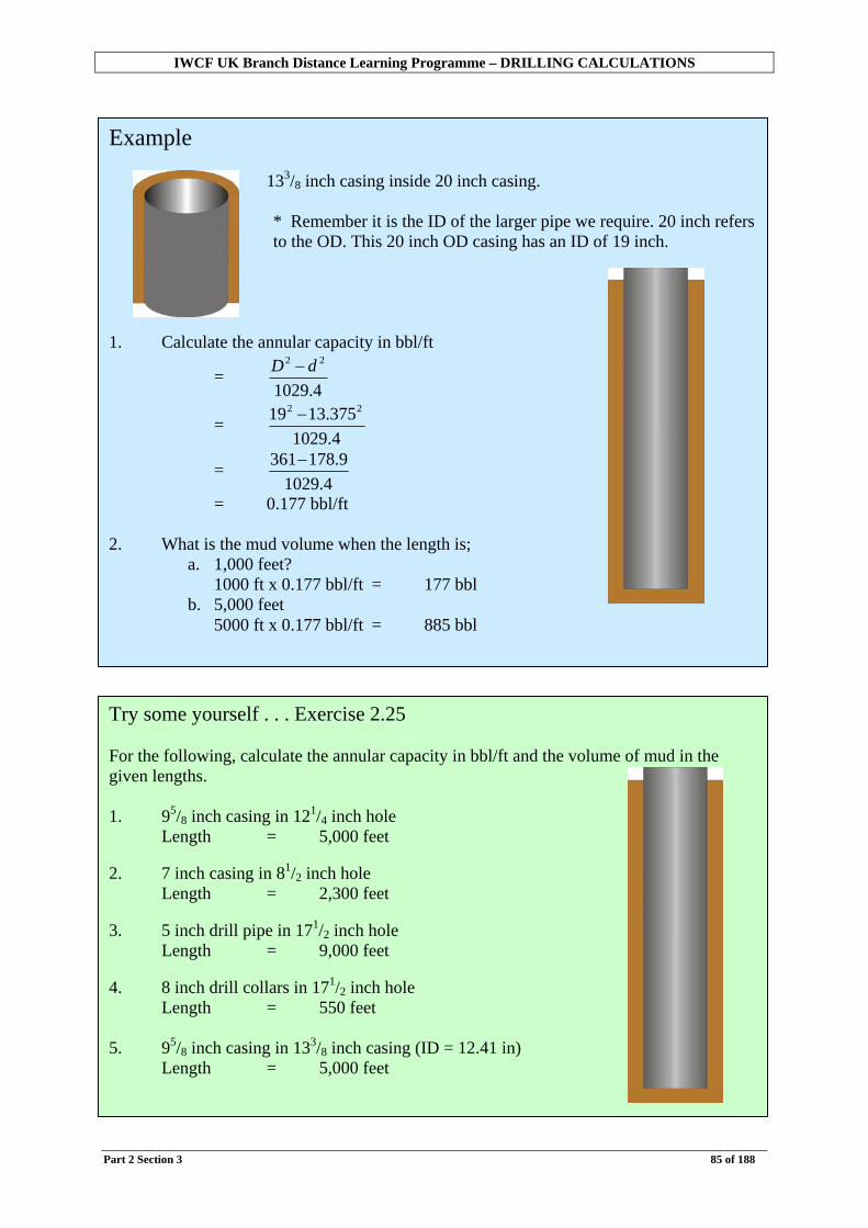
Example 133/8 inch casing inside 20 inch casing.
* Remember it is the ID of the larger pipe we require. 20 inch refers to the OD. This 20 inch OD casing has an ID of 19 inch.
1. Calculate the annular capacity in bbl/ft
= 4.1029
22 dD −
= 4.1029375.1319 22 −
= 4.1029
9.178361−
= 0.177 bbl/ft
2. What is the mud volume when the length is; a. 1,000 feet?
1000 ft x 0.177 bbl/ft = 177 bbl b. 5,000 feet
5000 ft x 0.177 bbl/ft = 885 bbl
Try some yourself . . . Exercise 2.25 For the following, calculate the annular capacity in bbl/ft and the volume of mud in the given lengths. 1. 95/8 inch casing in 121/4 inch hole
Length = 5,000 feet 2. 7 inch casing in 81/2 inch hole
Length = 2,300 feet 3. 5 inch drill pipe in 171/2 inch hole
Length = 9,000 feet 4. 8 inch drill collars in 171/2 inch hole
Length = 550 feet
5. 95/8 inch casing in 133/8 inch casing (ID = 12.41 in) Length = 5,000 feet

IWCF UK Branch Distance Learning Programme – DRILLING CALCULATIONS
Part 2 Section 3 86 of 188
A review of the formulae
Pipe capacity (bbl/ft) = 4.1029
2ID
ID = inside diameter of the pipe or hole in inches
Annular capacity (bbl/ft) = 4.1029
22 dD −
D = inside diameter of large pipe or hole in inches d = outside diameter of smaller pipe in inches
Volume (bbl) = length x capacity length in feet capacity in bbl/ft (can be used for pipe capacities or annular volumes)

IWCF UK Branch Distance Learning Programme – DRILLING CALCULATIONS
Part 2 Section 3 87 of 188
Try some yourself . . . Exercise 2.26 1. Calculate the following capacities in bbl/ft
a. 5 inch drill pipe ID 4.276 inch b. 5 inch heavy weight drill pipe ID 3 inch c. 65/8 inch drill pipe ID 5.965 inch d. 121/4 inch hole e. 81/2 inch hole f. 113/8 inch casing ID 12.681 inch g. 18 inch casing ID 17.755 inch h. 8 inch drill collars ID 3 inch
2. Calculate the following volumes in bbl. a. 15,000 feet of 5 inch drill pipe (ID 4.276 inch) b. 8,263 feet of 95/8 inch casing (ID 8.681 inch) c. 4,500 feet of 171/2 inch hole d. 950 feet of 8 inch drill collars (ID 2.81 inch) e. 550 feet of 5 inch HWDP (ID 3 inch)
3. Calculate the following annular capacities in bbl/ft. a. 5 inch drill pipe in 171/2 inch hole b. 8 inch drill collars in 121/4 inch hole c. 5 inch HWDP in 121/4 inch hole d. 7 inch casing in 81/2 inch hole e. 95/8 inch casing in 121/4 inch hole f. 5 inch drill pipe in 95/8 inch casing (ID 8.681 inch) g. 31/2 inch drill pipe in 7 inch casing (ID 6.184 inch)
4. Calculate the following annular volumes in bbl. a. 2,000 feet of 5 inch drill pipe in 121/4 inch hole b. 11,000 feet of 5 inch drill pipe in 133/8 inch casing (ID 12.41inch) c. 875 feet of 8 inch drill collar in 171/2 inch hole d. 480 feet of 91/2 inch drill collar in 26 inch hole e. 1,530 feet of 5 inch drill pipe in 26 inch hole.
IWCF UK Branch Distance Learning Programme – DRILLING CALCULATIONS
Part 2 Section 4 88 of 188
Section 4: Borehole Geometry – Surface BOP stack Some of the most important calculations performed in the oilfield involve calculating volumes of drilling mud (or other fluid) in a well. In order to do this we must understand the geometry (that is the relationship of the different sections) of a well. In this section we will explain how to divide the well into sections and calculate the length of these sections. We will then go on to calculate the volumes of mud in each section and the total volumes of mud in the well. In order to understand why the wells we drill are made up as they are, we will firstly discuss the process of drilling a well and the component systems a drilling rig must have. Objectives
• To discuss the process of drilling a well. • To give an outline of the components and systems on a drilling rig. • To introduce the general geometry of a borehole for a well with a surface BOP stack. • To show how to sketch the hole and to calculate the length of each section. • To show how to calculate annular volumes and drill string capacity. • To provide a step by step guide to enable the reader to perform these calculations.
It is assumed at this stage that the reader has a basic knowledge of the process of drilling a well. The next few pages, however, provides a recap on this subject.
Try this first… Exercise 2.27 Hole data 133/8 inch casing set at 6,000 feet (ID 12.41 inch) 121/4 inch hole drilled to 11,500 feet Drill string data 8 inch drill collars (ID = 2.8 inch) Length = 900 feet 5 inch HWDP (ID = 3 inch) Length = 810 feet 5 inch drill pipe (ID = 4.276 inch) Calculate the: 1. Annular volume (bbl). 2. Drill string capacity (bbl).
?

IWCF UK Branch Distance Learning Programme – DRILLING CALCULATIONS
Part 2 Section 4 89 of 188
How a well is drilled The information in the example question may have been a little confusing with various measurements and lengths given for different things. In order to clarify this, let us examine how a well is drilled, step by step. First of all, imagine digging a hole in the ground.
You can only dig so deep before the hole becomes unstable.
And will eventually collapse.
To prevent this, the sides of the hole need to be shored up.

IWCF UK Branch Distance Learning Programme – DRILLING CALCULATIONS
Part 2 Section 4 90 of 188
Digging can then proceed below the shored up section.
This process of making a hole, supporting the sides after a certain depth, then continuing deeper is exactly the process we use when drilling a well. Drilling a well … Once the rig is on location, we can start to drill (i.e. “spud in”).
In order to drill, we need a bit to break the rock, usually by a combination of rotation and weight (RPM and WOB). To remove the rock and clean the hole we circulate fluid down the drill string and up the annulus (these terms will be discussed in more detail later). This “Drilling Fluid” is more commonly referred to as “Mud”.
It is not possible to continue drilling with the same bit and mud until we reach our final depth. Why not? - After a certain depth the hole will be in danger of collapsing. - Soft formations at surface must be isolated.
As the well is drilled by a combination of weight on bit and rotation the cuttings are removed by the mud.
Of interest The term spudding is derived from an old English word “spudde” which was a tool for digging.
Drill bits

IWCF UK Branch Distance Learning Programme – DRILLING CALCULATIONS
Part 2 Section 4 91 of 188
So after drilling a certain depth of hole we must stop and run casing.
Most casing is cemented into place.
Thus, the whole well will be drilled in sections, with the bit becoming progressively smaller. Section by section … The first section (“Top Hole”) is normally drilled with a large diameter bit. Most common is to use a 26 in. bit with a 36 in. hole opener to drill a 36 in. diameter hole. This will normally be drilled to around 200-300 feet depending on the area. Note: In any type of well, the depths quoted are always from the rig floor. This is usually indicated by the term “Below Rotary Table” or BRT. Rigs drilling with a Kelly will use the term from “Rotary Kelly Bushings” or RKB. The 36 in. hole is then lined (or “Cased”) with a 30 in. diameter steel pipe (or “Casing”). This 30 in casing is then cemented into place.
Casing will; - support the hole; - isolate this section from the next; - provide a foundation for subsequent sections.
Cementing; - supports the casing; - seals off different zones.
30 in. refers to the OUTSIDE DIAMETER or O.D. of the casing.

IWCF UK Branch Distance Learning Programme – DRILLING CALCULATIONS
Part 2 Section 4 92 of 188
Our well now looks like this.
The next section is now drilled out below the casing. This hole size is usually 26 in. Once this section has been drilled (let us assume to 2000 ft), the next casing string must be run. This would normally be 20 in. casing (remember this refers to the O.D. of the casing). This casing runs from surface to the bottom of the casing (or “Shoe”) at 2000 ft. This casing is also cemented in place.
Drilling 36 in. Hole 30 in. Casing run and cemented
Casing and casing shoe Most types of casing comes in lengths of about 40 ft (joints). It is usually run into the well adding one joint at a time. The bottom (deepest) section is a short joint designed to guide the casing into the hole. This is called the casing shoe (or guide shoe).

IWCF UK Branch Distance Learning Programme – DRILLING CALCULATIONS
Part 2 Section 4 93 of 188
The next section is most commonly;
- 171/2 in. hole to about 5000 ft cased with 133/8 in. casing.
Then;
- 121/4 in. hole with 95/8 in. casing - 81/2 in. hole (possibly with 7 in. casing)
Thus the entire well is drilled, section by section.
So if a casing shoe is set at 2000 ft the casing is 2000 ft long.
Drilling 26 in. Hole 20 in. Casing run and cemented
133/8 in. Casing run and cemented
Drilling 171/2 in. Hole

IWCF UK Branch Distance Learning Programme – DRILLING CALCULATIONS
Part 2 Section 4 94 of 188
Components of a rig and well
In order to drill a well, certain basic systems need to be provided.
These are; - Power systems - Hoisting system - Circulating system - Rotating system - Mud system (drilling fluid) - Blowout prevention system
(BOP)
Below ground there is the well itself and the drill string.
Hoisting system Consists of the derrick and drawworks
Rotating system Top drive or Kelly to rotate the string
Circulating system Mud is circulated Mud pits mud pump top drive (Kelly) drill string bit
annulus return flowline mud pits
Drilling fluid The drilling fluid (or “mud”);
- balances formation pressure
- cools and lubricates bit - removes cuttings
Power system Engines and generators

IWCF UK Branch Distance Learning Programme – DRILLING CALCULATIONS
Part 2 Section 4 95 of 188
Blow out prevention system The blow out preventer (BOP) stack consists of a series of hydraulically operated valves on the top of the well. They are designed to shut in the well in case of emergency (e.g. flow of formation fluid from the well). This allows us to perform well kill operations to bring the well under control. BOPs are designed to hold back high pressure from the well (up to 15000 psi). A typical BOP stack might consist of several types of valves. Annular preventers are circular preventers designed to close around almost anything including empty hole (e.g. drill pipe, drill collars etc.) Ram preventers are gate type valves. They can be fitted with different types of block to allow them to close around drill pipe, open hole or to shear (cut) the drill pipe. Choke and kill lines are used for well kill operations.

IWCF UK Branch Distance Learning Programme – DRILLING CALCULATIONS
Part 2 Section 4 96 of 188
In this section we will deal with the type of well drilled from land rigs, jack ups and platforms.
These installations are “fixed” or bottom supported. The well head and BOP stack are directly below the rig floor (rotary table). Casing is then suspended from the well head. All measurements are from the rotary table and the depth of the casing shoe is equal to the length of the casing.

IWCF UK Branch Distance Learning Programme – DRILLING CALCULATIONS
Part 2 Section 4 97 of 188
The Well . . . At any point after the top hole section, the well will usually consist of a string of casing with an open hole below.
Casing sizes Casing is named by its Outside Diameter (OD). For example, 133/8 in casing has an OD of 133/8 in and a smaller Internal Diameter (ID). In addition to the OD, next to each casing, a weight in pounds per foot (lb/ft) is given. This is because casing is manufactured with different wall thicknesses, and consequently different weights and strengths. Heavier or thicker wall casing has a smaller ID. This information can usually be obtained from books or tables.
Common casing sizes 20 in casing (106.5 lb/ft) ID 19.0 in 185/8 in casing (87.5 lb/ft) ID 17.755 in 133/8 in casing (68 lb/ft) ID 12.415 in 95/8 in casing (47 lb/ft) ID 8.681 in 7 in casing (32 lb/ft) ID 6.094 in
Symbol used to represent casing shoe
Common hole / bit sizes 36 in 81/2 in 26 in 6 in 171/2 in 43/4 in 121/4 in The diameter of the hole is obviously the same as the diameter of the bit
For example 95/8 inch casing OD (inches) Weight (lb/ft) ID (inches) 95/8 54.5 12.615 95/8 61.0 12.515 95/8 68.0 12.415

IWCF UK Branch Distance Learning Programme – DRILLING CALCULATIONS
Part 2 Section 4 98 of 188
Try some yourself . . . Exercise 2.28 1. The 30 in conductor has been run and cemented to 300 ft Below Rotary
Table (BRT).
a) What would be the most likely bit size for the next section?
b) What would be the next casing string to
be run? 2. After the second string of casing is run we
will now drill 171/2 in hole, and after that, progressively smaller hole sizes.
Fill in the most appropriate casing size for the following hole sections. Hole section Casing
a) 171/2 in in b) 121/4 in in c) 81/2 in in
Depths in a well Depths in a well are normally given from the rotary table, regardless of whether drilling from a land rig, jack up, platform or floating rig. They are normally quoted as; BRT - Below Rotary Table or sometimes; RKB - Rotary Kelly Bushings (RKB is the term used on rigs drilling with a Kelly rather than a top drive).

IWCF UK Branch Distance Learning Programme – DRILLING CALCULATIONS
Part 2 Section 4 99 of 188
The drill string …. In order to drill we need a drill string usually made up of drill pipe and a bottom hole assembly (BHA). The drill string has several functions including;
- allowing us to put weight on the bit (WOB) - allowing us to rotate the bit (RPM) - providing a path to circulate mud down to the bit.
A typical drill string
• Drill collars are heavier than drill pipe to provide weight for WOB and rigidity to control direction.
• Heavy weight drill pipe is used between drill collars and drill pipe (to provide a transition between drill collars and normal drill pipe) and can be used to provide WOB.
• Drill collars and heavy weight drill pipe together are known as the Bottom Hole Assembly (BHA).
• Drill pipe runs from the BHA back to surface.
BHA
Drill pipe 5 in drill pipe (19.5 lb/ft) ID 4.276 in
HWDP 5 in HWDP (49.3 lb/ft) ID 3.0 in
Drill collar 8 in drill collar (147.0 lb/ft) ID 3 in (approx)

IWCF UK Branch Distance Learning Programme – DRILLING CALCULATIONS
Part 2 Section 4 100 of 188
As with casing, drill string tubulars are named by their OD. Each type of pipe also has a weight (lb/ft). The ID varies with the pipe weight. Example of pipe sizes Drill pipe sizes OD ID 31/2 in (15.5 lb/ft) 2.602 in 5 in (19.5 lb/ft) 4.276 in 65/8 in (25.2 lb/ft) 5.965 in HWDP sizes
OD ID 31/2 in (25.3 lb/ft) 21/16 in 5 in (49.3 lb/ft) 3 in Drill collar sizes OD ID 43/4 in (46.8 lb/ft) 21/4 in (approx) 63/4 in (97.8 lb/ft) 3 in (approx) 8 in (147.0 lb/ft) 3 in (approx) 91/2 in (217.2 lb/ft) 3 in (approx The internal diameter varies depending on the weight, so drill pipe with the same OD may come in different weights with different IDs. It is important to check this.
For example 5 in OD drill pipe OD (in) Wt (lb/ft) ID (in) 5 16.25 4.408 5 19.5 4.276 5 20.5 4.214
Tool joints Drill pipe is joined together by means of screwed threads. These are cut into tool joints with male and female threads at opposite ends. The OD of the tool joint is greater than the OD of the pipe to provide strength. Pipe nominal Weight Approx. TJ OD Size (lb/ft) (inches) 31/2 13.3 43/4 5 19.5 63/8 65/8 25.2 8

IWCF UK Branch Distance Learning Programme – DRILLING CALCULATIONS
Part 2 Section 4 101 of 188
Hole geometry - Drill string capacity and annular volumes Typically, a diagram of a hole might look like this. In order to calculate volumes, we need to know the following;
- casing OD, ID and depth; - open hole size and depth; - drill collar OD, ID and length; - Drill pipe OD, ID and length.
Why calculate volumes? Drilling fluid (“mud”) is important in the process of drilling a well. Its functions include;
- balancing formation pressure (by having sufficient mud density) - transporting cuttings (mud viscosity) - cooling and lubricating the bit as it is circulated around the well.
In order to monitor and maintain the drilling fluid, we must know the volume. It is also important to make sure the hole remains full of the right quantity of mud. To do this we must be able to calculate the volume of mud inside the various sections of the hole.

IWCF UK Branch Distance Learning Programme – DRILLING CALCULATIONS
Part 2 Section 4 102 of 188
Example calculation Lets take an example well
Hole data 133/8 in Casing (ID 12.415 in) Casing shoe set at 5,000 ft 121/4 in Open hole drilled to 9,000 ft Drill string data 8 in Drill collars (ID 2.81 in) Length 1,000 ft 5 in HWDP (ID 3 in ) Length 800 ft 5 in drill pipe (ID 4.276 in)

IWCF UK Branch Distance Learning Programme – DRILLING CALCULATIONS
Part 2 Section 4 103 of 188
First of all examine the drill string We need to calculate the capacity of the drill string. Capacity is the space inside the pipe.
Firstly, calculate the length of each section. Drill collars Length = 1,000 ft (from information given) HWDP Length = 800 ft (from information given) Drill pipe Length = Total depth – Drill collar length – HWDP length = 9,000 – 1,000 - 800 = 7,200 ft
Hole data 133/8 in Casing (ID 12.415 in) Casing shoe set at 5,000 ft 121/4 in Open hole drilled to 9,000 ft Drill string data 8 in Drill collars (ID 2.81 in) Length 1,000 ft 5 in HWDP (ID 3 in) Length 800 ft 5 in drill pipe (ID 4.276 in)
It is useful at this stage to check that the sum of the lengths of the sections is the same as the total depth of the well…
1,000 ft + 800 ft + 7,200 ft = 9,000 ft

IWCF UK Branch Distance Learning Programme – DRILLING CALCULATIONS
Part 2 Section 4 104 of 188
We already know the diameters for each type of pipe.
Drill pipe Length : 7,200 ft OD : 5 in ID : 4.276 in
Drill collars Length : 1,000 ft OD : 8 in ID : 2.81 in
Try some yourself . . . Exercise 2.29 Calculate the missing lengths.
1. Hole depth 10,000 ft Drill collars 700 ft HWDP 400 ft Drill pipe ft 2. Hole depth 12,000 ft Drill collars ft HWDP 600 ft Drill pipe 10,400 ft 3. Hole depth ft Drill collars 850 ft HWDP 650 ft Drill pipe 14,000 ft 4. Hole depth 22,350 ft Drill collars 937 ft HWDP 744 ft Drill pipe ft
HWDP Length : 800 ft OD : 5 in ID : 3 in

IWCF UK Branch Distance Learning Programme – DRILLING CALCULATIONS
Part 2 Section 4 105 of 188
Next, calculate the capacity per foot for each drill string component Drill pipe (OD 5 in ID 4.276 in)
Capacity (bbl/ft) = 4.1029
276.4 2
= 4.1029
28.18
= 0.01776 bbl/ft HWDP (OD 5 in ID 3 in)
Capacity (bbl/ft) = 4.1029
32
= 4.1029
9
= 0.0087 bbl/ft Drill collars (OD 8 in ID 2.81 in)
Capacity (bbl/ft) = 4.1029
81.2 2
= 4.1029
9.7
= 0.0077 bbl/ft
The formula
4.1029ID (bbl/ft)Capacity
2
=
ID = Internal diameter of pipe in inches 1029.4 = Constant to allow diameters in inches to give capacities
in bbl/ft
Accuracy Capacities in bbl/ft are normally quoted to 4 (occasionally 5) decimal places. This accuracy is required because we will be multiplying them by numbers 10,000 plus.

IWCF UK Branch Distance Learning Programme – DRILLING CALCULATIONS
Part 2 Section 4 106 of 188
Now, calculate the capacity in barrels for each component Drill pipe Length = 7,200 ft Capacity = 0.01776 bbl/ft Volume (bbl) = 7,200 x 0.01776 = 127.9 bbl (1 decimal place) HWDP Length = 800 ft Capacity = 0.0087 bbl/ft Volume (bbl) = 800 x 0.0087 = 7.0 bbl (1 decimal place) Drill collars Length = 1,000 ft Capacity = 0.0077 bbl/ft Volume (bbl) = 1,000 x 0.0077 = 7.7 bbl (1decimal place) Total drill string capacity = drill pipe volume + HWDP volume + Drill collar volume = 127.9 + 7.0 + 7.7 = 142.6 bbl
The formula Volume (bbl) = length x capacity length = length of section in feet capacity = capacity in bbl/ft
Accuracy When dealing with volumes of mud in the well it is normal to work to an accuracy for the final answer to 0.1 of a barrel (i.e. accurate to 1 decimal place).
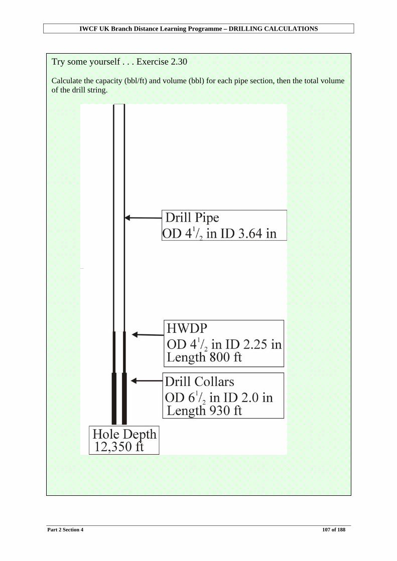
IWCF UK Branch Distance Learning Programme – DRILLING CALCULATIONS
Part 2 Section 4 107 of 188
Try some yourself . . . Exercise 2.30 Calculate the capacity (bbl/ft) and volume (bbl) for each pipe section, then the total volume of the drill string.

IWCF UK Branch Distance Learning Programme – DRILLING CALCULATIONS
Part 2 Section 4 108 of 188
Now examine the annular volumes
The annulus can be split into three sections.
We know the diameters for each section …
Section 1 Casing ID : 12.415 in Drill pipe OD : 5 in
Section 2 Hole ID : 12.25 in Drill pipe OD : 5 in
Section 3 Hole ID : 12.25 in Drill collar OD : 8 in
The ANNULUS is the space between the OUTSIDE of the drill string and the INSIDE of the casing or open hole.
Because the outside diameters are the same, HWDP can be treated as drill pipe for calculating annular volumes.

IWCF UK Branch Distance Learning Programme – DRILLING CALCULATIONS
Part 2 Section 4 109 of 188
Next we need the lengths of each section.
Let’s have a closer look at how to calculate the length of section 2.

IWCF UK Branch Distance Learning Programme – DRILLING CALCULATIONS
Part 2 Section 4 110 of 188
Now we have all the information we need to continue.
Section 1: Drill pipe in casing Length : 5,000 ft Casing ID : 12.415 in Drill pipe OD : 5 in
Section 2: Drill pipe in open hole Length : 3,000 ft Open hole ID : 12.25 in Drill pipe OD : 5 in
Section 3: Drill collars in open hole Length : 1,000 ft Open hole ID : 12.25 in Drill collar OD : 8 in
It is again useful at this stage to check that the sum of the lengths of the three sections is the same as the total depth of the well… 5,000 ft + 3,000 ft + 1,000 ft = 9,000 ft
Try some yourself . . . Exercise 2.31 For the following well, calculate the lengths of each section.
Section 1 Drill pipe in casing annulus Section 2 Drill pipe in open hole Section 3 Drill collars in open hole

IWCF UK Branch Distance Learning Programme – DRILLING CALCULATIONS
Part 2 Section 4 111 of 188
To calculate the annular volume Section 1
Annular capacity (bbl/ft) = 4.1029
5415.12 22 −
= 4.10292513.154 −
= 4.1029
13.129
= 0.1254 bbl/ft Annular volume (bbl) = 5,000 x 0.1255 = 627.0 bbl
The formulae
Annular capacity (bbl/ft) = 4.1029
22 dD −
Annular volume = length x annular capacity D = Internal diameter of casing or open hole in inches d = Outside diameter of pipe in inches 1029.4 = Constant

IWCF UK Branch Distance Learning Programme – DRILLING CALCULATIONS
Part 2 Section 4 112 of 188
Section 2
Annular capacity (bbl/ft) = 4.1029525.12 22 −
= 4.10292506.150 −
= 4.1029
06.125
= 0.1215 bbl/ft Annular volume (bbl) = 3,000 x 0.1215 = 364.5 bbl Section 3
Annular capacity (bbl/ft) = 4.1029825.12 22 −
= 4.10296406.150 −
= 4.1029
06.86
= 0.0836 bbl/ft Annular volume (bbl) = 1,000 x 0.0836 = 83.6 bbl Total annular volume = 627.0 bbls + 364.5 bbls + 83.6 bbls = 1,075.1 bbl The Total Annular Volume is the sum of all the sections.

IWCF UK Branch Distance Learning Programme – DRILLING CALCULATIONS
Part 2 Section 4 113 of 188
Now we know how to calculate both annular volumes and drill string capacities. Here are some tips for carrying out more complicated examples:
• Draw a clear, labelled diagram with all depths on.
• Keep precise step by step notes of your calculations as you go. This may help later.
• Estimate your answers to check for accuracy.

IWCF UK Branch Distance Learning Programme – DRILLING CALCULATIONS
Part 2 Section 4 114 of 188
Worked Example Now we will try a complete example from start to finish.
Hole data 95/8 in Casing (ID 8.681 in) set at 13,500 ft 81/2 in Open hole drilled to 16,000ft
Drill string data 6 in Drill collars (ID 2.5 in) Length 800 ft 5 in HWDP (ID 3 in) Length 750 ft 5 in Drill pipe (ID 4.276 in)
Calculate: a. Drill string capacity in barrels b. Annular volume in barrels c. Total volume in barrels
Step 1 – Draw a diagram Step 2 – Calculate drill string lengths Step 3 – Calculate annular section lengths Step 4 – Calculate drill string capacity Step 5 – Calculate annular volume

IWCF UK Branch Distance Learning Programme – DRILLING CALCULATIONS
Part 2 Section 4 115 of 188
Step 1 Draw a diagram and label clearly
Step 2
Calculate the lengths of each section of the drill string
Drill collars Length = 800 ft HWDP Length = 750 ft Drill pipe Length = Total depth – Drill collar length – HWDP length = 16,000 – 800 - 750 = 14,450 ft

IWCF UK Branch Distance Learning Programme – DRILLING CALCULATIONS
Part 2 Section 4 116 of 188
Step 3 Calculate the lengths of each section of the annulus.
1. Drill pipe in casing = 13,500 ft 2. Drill pipe/HWDP in open hole = Total depth – Casing length – Drill collar length = 16,000 – 13,500 – 800 = 1,700 ft 3. Drill collars in open hole = Length of collars = 800 ft 4. Check the sum of the section lengths against Total Depth
13,500 + 1,700 + 800 = 16,000 ft Total Depth = 16,000 ft
Step 4 Calculate the capacity (bbl/ft) and volume (bbl) of each section of the drill string
Drill pipe
Capacity (bbl/ft) = 4.1029
276.4 2
= 0.01776 bbl/ft Volume (bbl) = 14,450 x 0.01776 = 256.6 bbl
Remember
Capacity (bbl/ft) = 4.1029
2ID
Volume (bbl) = length x capacity

IWCF UK Branch Distance Learning Programme – DRILLING CALCULATIONS
Part 2 Section 4 117 of 188
HWDP
Capacity (bbl/ft) = 4.1029
32
= 0.0087 bbl/ft Volume (bbl) = 750 x 0.0087 = 6.5 bbl Drill collars
Capacity (bbl/ft) = 4.1029
5.2 2
= 0.0061 bbl/ft Volume (bbl) = 800 x 0.0061 = 4.9 bbl Total drill string capacity = Drill pipe + HWDP + Drill collars = 256.6 + 6.5 + 4.9 = 268 bbl

IWCF UK Branch Distance Learning Programme – DRILLING CALCULATIONS
Part 2 Section 4 118 of 188
Step 5 Calculate the annular capacity (bbl/ft) and annular volume (bbl) for each section, then the total annular volume (bbl).
Section 1 Drill pipe in casing
Annular capacity (bbl/ft) = 4.10295681.8 22 −
= 4.10292536.75 −
= 1029
36.50
= 0.0489 bbl/ft Annular volume (bbl) = 13,500 x 0.0489 = 660.2 bbl Section 2 Drill pipe/HWDP in open hole
Annular capacity (bbl/ft) = 4.102955.8 22 −
= 4.10292525.72 −
= 0.0459 bbl/ft Annular volume (bbl) = 1,700 x 0.0459 = 78.0 bbl
Remember
Annular Capacity (bbl/ft) = 4.1029
22 dD −
Annular Volume (bbl) = length x annular capacity
D = inside diameter of larger pipe or hole. d = outside diameter of smaller pipe
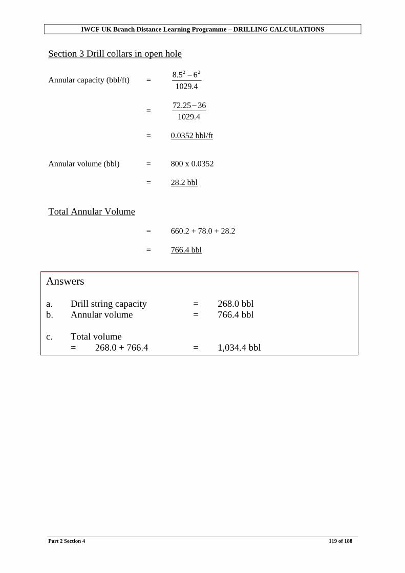
IWCF UK Branch Distance Learning Programme – DRILLING CALCULATIONS
Part 2 Section 4 119 of 188
Section 3 Drill collars in open hole
Annular capacity (bbl/ft) = 4.102965.8 22 −
= 4.10293625.72 −
= 0.0352 bbl/ft Annular volume (bbl) = 800 x 0.0352 = 28.2 bbl Total Annular Volume = 660.2 + 78.0 + 28.2 = 766.4 bbl
Answers a. Drill string capacity = 268.0 bbl b. Annular volume = 766.4 bbl c. Total volume
= 268.0 + 766.4 = 1,034.4 bbl

IWCF UK Branch Distance Learning Programme – DRILLING CALCULATIONS
Part 2 Section 4 120 of 188
Try some yourself . . . Exercise 2.32 Draw your own diagrams or a volume worksheet is included at the end of this section to use if you wish. 1. Hole data
133/8 inch Casing (ID 12.415 inch) set at 4,734 feet 121/4 inch Open hole drilled to 8,762 feet 8 inch Drill collars (ID 2.81 inch) Length 750 feet 5 inch HWDP (ID 3.0 inch) Length 450 feet 5 inch Drill pipe (ID 4.276 inch) Calculate: a. Drill string capacity (bbl) b. Annular volume (bbl)
a Hole data
185/8 in Casing (ID 17.76 in) set at 2,800 feet 17½ in Open hole drilled to 5,350 feet 9½ inch Drill collars (ID 3.0 inch) Length 350 feet 8 inch Drill collars (ID 2.81 inch) Length 300 feet 5 inch HWDP (ID 3.0 inch) Length 375 feet 5 inch Drill pipe (ID 4.276 inch) Calculate: a. Drill string capacity (bbl) b. Annular volume (bbl) c. Total volume (bbl) Continued over the page
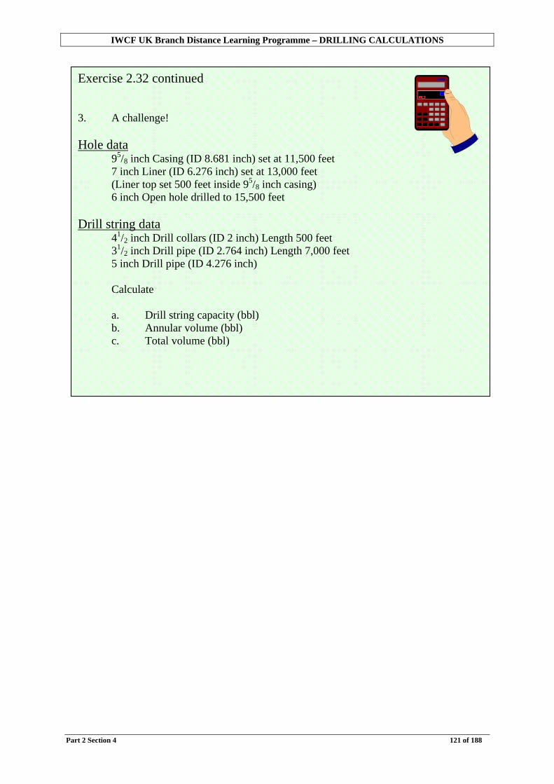
IWCF UK Branch Distance Learning Programme – DRILLING CALCULATIONS
Part 2 Section 4 121 of 188
Exercise 2.32 continued 3. A challenge! Hole data
95/8 inch Casing (ID 8.681 inch) set at 11,500 feet 7 inch Liner (ID 6.276 inch) set at 13,000 feet (Liner top set 500 feet inside 95/8 inch casing) 6 inch Open hole drilled to 15,500 feet
Drill string data 41/2 inch Drill collars (ID 2 inch) Length 500 feet 31/2 inch Drill pipe (ID 2.764 inch) Length 7,000 feet 5 inch Drill pipe (ID 4.276 inch) Calculate a. Drill string capacity (bbl) b. Annular volume (bbl) c. Total volume (bbl)

IWCF UK Branch Distance Learning Programme – DRILLING CALCULATIONS
Part 2 Section 4 122 of 188

IWCF UK Branch Distance Learning Programme – DRILLING CALCULATIONS
Part 2 Section 5 123 of 188
Section 5: Borehole Geometry – Subsea BOP stack In section four we looked at volume calculations in wells drilled with a surface BOP stack. In this section we will examine the differences between this type of well and those drilled from floating rigs with a subsea BOP stack. We will then explain how to calculate volumes and capacities for wells with a subsea BOP stack. Objectives
• To discuss the differences in borehole geometry between surface and subsea BOP stacks.
• To calculate pipe capacities and hole volumes for wells with a subsea BOP stack. NOTE: THIS SECTION SHOULD BE USED IN CONJUNCTION WITH SECTION 4
WHICH EXPLAINS THE BASIC VOLUME CALCULATIONS.
Try this first…Exercise 2.33 Well data 133/8 in casing (ID 12.515 in) Depth 5,908 ft 121/4 in open hole Depth 9,923 ft 20 in marine riser (ID 19 in) Length 550 ft Choke line (ID 3 in) Length 550 ft Drill string 5 in drill pipe (ID 4.276 in) 5 in HWDP (ID 3 in) Length 810 ft 8 in drill collars (ID 2.8 in) Length 558 ft Calculate the: 1. Drill string capacity (bbl) 2. Annular volume (bbl)
?

IWCF UK Branch Distance Learning Programme – DRILLING CALCULATIONS
Part 2 Section 5 124 of 188
Differences between operations with surface BOP stack and subsea BOP stack So far we have dealt with the type of well drilled from a land rig, platform or jack up type rig.
These types of installation are “fixed” relative to land or the seabed. In this case the wellhead and BOP stack is directly below the rig floor. The casing is suspended from the wellhead. Thus the length of the casing is the same as the shoe depth.
This is termed a surface BOP stack.

IWCF UK Branch Distance Learning Programme – DRILLING CALCULATIONS
Part 2 Section 5 125 of 188
Wells drilled from floating installations such as semi-submersibles and drillships must be designed differently to allow for movement of the rig. On floating rigs, generally, the wellhead and BOP stack are on the sea floor. Casing is then hung from the wellhead. In this case the length of casing is not the same as the shoe depth. Remember depths are quoted from the rotary table. When drilling, mud returns are brought to surface via the Marine Riser. The marine riser is a large diameter pipe running from the top of the BOP stack to the rig. It will have a flexible joint and a slip joint to allow for rig movement.
The marine riser is not designed to hold pressure in the same way that casing is, it is simply a conduit. In a well control situation therefore, once the BOPs are closed, returns cannot be brought up the riser. In this case returns are brought up one of the two lines on the outside of the riser (the choke and kill lines).
Choke and kill lines are designed to hold the same pressure as the BOPs.

IWCF UK Branch Distance Learning Programme – DRILLING CALCULATIONS
Part 2 Section 5 126 of 188
Normal operations (e.g. Drilling)
Mud returns to surface via the marine riser
Well kill operations (BOP closed)
Mud returns to surface via the choke line

IWCF UK Branch Distance Learning Programme – DRILLING CALCULATIONS
Part 2 Section 5 127 of 188
Calculations Essentially we now have an additional section included in the annulus volume calculation. The dimensions of the drill string are treated exactly the same as a surface BOP well so the calculations for drill string capacity are the same in both cases. Example
Well data 133/8 in casing (ID 12.415 in) Depth 5,000 ft 121/4 in open hole Depth 9,000 ft 20 in marine riser (ID 19 in) Length 1,000 ft Choke line (ID 3 in) Drill string data 8 in drill collars (ID 2.81 in) Length 1,000 ft 5 in HWDP (ID 3 in ) Length 800 ft 5 in drill pipe (ID 4.276 in)
Hole depth 9,000 ft

IWCF UK Branch Distance Learning Programme – DRILLING CALCULATIONS
Part 2 Section 5 128 of 188
Drill string capacity
Drill collars
Length = 1,000 ft (given)
Capacity (bbl/ft) = 4.1029
81.2 2
= 0.0077 bbl/ft
Volume (bbl) = 1,000 x 0.0077 = 7.7 bbl HWDP
Length = 800 ft (given)
Capacity (bbl/ft) = 4.1029
32
= 0.0087 bbl/ft
Volume (bbl) = 800 x 0.0087 = 7.0 bbl Drill pipe
Length = 9,000 ft – 1,000 ft – 800 ft = 7,200 ft
Capacity (bbl/ft) = 4.1029
276.4 2
= 0.01776 bbl/ft
Volume (bbl) = 7,200 x 0.01776 = 127.9 bbl
Remember
Capacity (bbl/ft) = 4.1029
2ID
Volume (bbl) = length x capacity

IWCF UK Branch Distance Learning Programme – DRILLING CALCULATIONS
Part 2 Section 5 129 of 188
Total drill string capacity = Drill collars + HWDP + Drill pipe = 7.7 + 7.0 + 127.9 = 142.6 bbl

IWCF UK Branch Distance Learning Programme – DRILLING CALCULATIONS
Part 2 Section 5 130 of 188
Annular volumes (well shut in)
The annulus is now split into 4 sections. The volume of mud in the marine riser will be dealt with later.
The first thing to do is to calculate the length of each section. Section Lengths Section 1 Choke line Length = 1,000 ft (Same length as the riser) Section 2 Drill pipe in casing Casing shoe set at 5,000 ft BRT. Casing runs from sea bed (1,000 ft BRT). Length of casing = 5,000 – 1,000 = 4,000 ft Section 3 Drill pipe/HWDP in open hole Length = hole depth – shoe depth – drill collar length = 9,000 – 5,000 – 1,000 = 3,000 ft Section 4 Drill collars in open hole Length = length of collars = 1,000 ft

IWCF UK Branch Distance Learning Programme – DRILLING CALCULATIONS
Part 2 Section 5 131 of 188
Volumes Now we have the lengths, we can calculate the annular capacities (bbl/ft) then the annular volumes (bbl).
Remember
Capacity (bbl/ft) = 4.1029
2ID
Annular Capacity (bbl/ft) = 4.1029
22 dD −
Where D = Inside diameter of large pipe or hole d = outside diameter of smaller pipe Annular Volume (bbl) = length x annular capacity

IWCF UK Branch Distance Learning Programme – DRILLING CALCULATIONS
Part 2 Section 5 132 of 188
Section 1 Choke line Length = 1,000 ft
Capacity (bbl/ft) = 4.1029
2ID
= 4.1029
32
= 0.0087 bbl/ft Volume (bbl) = 1,000 x 0.0087 = 8.7 bbl Section 2 Drill pipe in casing Length = 4,000 ft
Annular capacity (bbl/ft) = 4.1029
5415.12 22 −
= 0.1254 bbl/ft Annular volume (bbl) = 4,000 x 0.1255 = 501.6 bbl Section 3 Drill pipe/HWDP in open hole Length = 3,000 ft
Annular capacity (bbl/ft) = 4.1029525.12 22 −
= 0.1215 bbl/ft Annular volume (bbl) = 3,000 x 0.1215 = 364.5 bbl

IWCF UK Branch Distance Learning Programme – DRILLING CALCULATIONS
Part 2 Section 5 133 of 188
Section 4 Drill collars in open hole Length = 1,000 ft
Annular capacity (bbl/ft) = 4.1029825.12 22 −
= 0.0836 bbl/ft Annular volume (bbl) = 1,000 x 0.0836 = 83.6 bbl Total Annular Volume (via choke line) Total annular volume (bbl) = choke line volume + drill pipe in casing annular
volume + drill pipe/HWDP in open hole annular volume + drill collar in open hole annular volume
= 8.7 + 501.6 + 364.5 + 83.6 = 958.4 bbl Marine riser We also need to know the volume of mud in the marine riser.
Length of marine riser = 1,000 ft
Annular capacity = 4.1029
22 dD −
(with drill pipe in riser)
= 4.1029519 22 −
= 0.3264 bbl/ft Annular volume = length x annular capacity = 1,000 x 0.3264 = 326.4 bbl
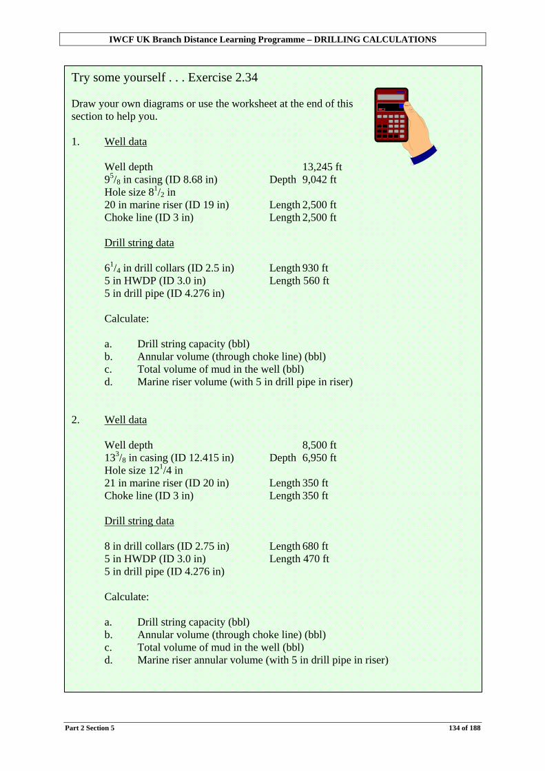
IWCF UK Branch Distance Learning Programme – DRILLING CALCULATIONS
Part 2 Section 5 134 of 188
Try some yourself . . . Exercise 2.34 Draw your own diagrams or use the worksheet at the end of this section to help you. 1. Well data
Well depth 13,245 ft 95/8 in casing (ID 8.68 in) Depth 9,042 ft Hole size 81/2 in 20 in marine riser (ID 19 in) Length 2,500 ft Choke line (ID 3 in) Length 2,500 ft Drill string data 61/4 in drill collars (ID 2.5 in) Length 930 ft 5 in HWDP (ID 3.0 in) Length 560 ft 5 in drill pipe (ID 4.276 in) Calculate: a. Drill string capacity (bbl) b. Annular volume (through choke line) (bbl) c. Total volume of mud in the well (bbl) d. Marine riser volume (with 5 in drill pipe in riser)
2. Well data
Well depth 8,500 ft 133/8 in casing (ID 12.415 in) Depth 6,950 ft Hole size 121/4 in 21 in marine riser (ID 20 in) Length 350 ft Choke line (ID 3 in) Length 350 ft Drill string data 8 in drill collars (ID 2.75 in) Length 680 ft 5 in HWDP (ID 3.0 in) Length 470 ft 5 in drill pipe (ID 4.276 in) Calculate: a. Drill string capacity (bbl) b. Annular volume (through choke line) (bbl) c. Total volume of mud in the well (bbl) d. Marine riser annular volume (with 5 in drill pipe in riser)
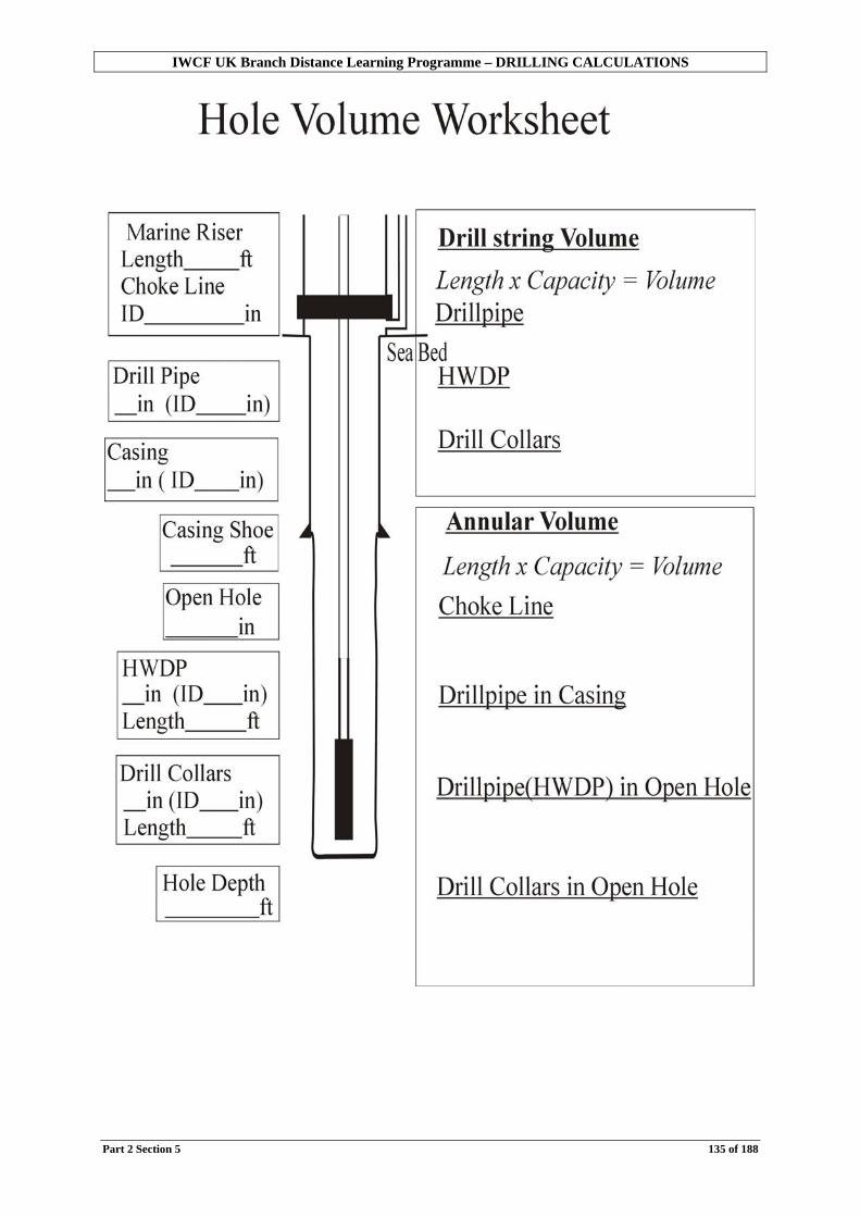
IWCF UK Branch Distance Learning Programme – DRILLING CALCULATIONS
Part 2 Section 5 135 of 188

IWCF UK Branch Distance Learning Programme – DRILLING CALCULATIONS
Part 2 Section 6 136 of 188
This page is deliberately blank

IWCF UK Branch Distance Learning Programme – DRILLING CALCULATIONS
Part 2 Section 6 137 of 188
Section 6: Pump Output, Pump Strokes, Time In Sections 4 and 5 we calculated the volumes of mud in a well. In addition to this, it is important that we understand what happens when we circulate mud around the well, as we do most of the time when drilling, or indeed circulating out a kick. In this section we will look at how a mud pump works and how much mud it actually pumps. We will then show how to calculate the pump strokes required to circulate mud around a well. Objectives
• To discuss why we need to calculate pump output and strokes. • To be able to calculate pump outputs. • To be able to calculate the number of pump strokes required to circulate mud around
the well.
Try this first…Exercise 2.35 Given the following well information
Drill string capacity : 143.7 bbl Annular volume : 1075.0 bbl Pump output : 0.109 bbl/stroke Calculate; 1. The pump strokes required to circulate mud down the drill string (i.e. surface
to the bit). 2. The pump strokes required to circulate mud up the annulus (i.e. bit to
surface).
3. The pump strokes required for a complete circulation. 4. The time required for a complete circulation at 30 strokes per minute.
?

IWCF UK Branch Distance Learning Programme – DRILLING CALCULATIONS
Part 2 Section 6 138 of 188
Review of circulating system A typical circulating system of a drilling rig consists of;
Mud pits Mud pumps Surface lines Drill string Annulus Return flow line Mud cleaning equipment
So, while drilling, mud is circulated using the mud pumps, from the mud pits, to the drill string, down the drill string, through the bit and then up the annulus. The mud then returns to the pits via the return flow line and a series of mud cleaning equipment to remove cuttings. We should therefore have a closed system where the volume of mud does not change (apart from a small amount as the hole is drilled deeper). Mud pumps and pump output Most mud pumps on rigs nowadays are “single acting triplex pumps”. That means they have three cylinders, each forcing mud out as the piston moves in one direction only.
The output capability of a mud pump is normally given in barrels per stroke, that is how much mud is displaced during one cycle of the pump. That is for all 3 cylinders of the pump. The terms used for this are displacement (bbl/stroke) or output (bbl/stroke)

IWCF UK Branch Distance Learning Programme – DRILLING CALCULATIONS
Part 2 Section 6 139 of 188
The output per stroke for a triplex pump depends on two dimensions; - the diameter of the piston or cylinder (known as a liner) - the length of the stroke.
Pump output per stroke (or displacement) can be calculated if the liner size and stroke length are known. This calculation is usually not necessary as liners come in standard sizes and therefore have standard displacements (outputs).
Liners The cylinders on a mud pump are changeable in the field and come in different diameters to give different outputs. They are known as liners.
Of interest – calculating pump output For a pump with a 12 in stroke. 1. Calculate the bbl/ft of the liner
bbl/ft = 1029.4
IDliner 2
So one cylinder with a 12 in (1 ft) stroke will put out;
bbl = foot 11029.4
IDliner 2
×
2. Calculate the output for all 3 cylinders
bbl/stroke = 311029.4
IDliner 2
×⎥⎦
⎤⎢⎣
⎡×
3. Multiply out the constants
bbl/stroke = 002914.0IDliner 2 ×
So for 7 in liners the output would be;
bbl/stroke = 002914.072 × = 0.1428 bbl/stroke (to 4 decimal places)

IWCF UK Branch Distance Learning Programme – DRILLING CALCULATIONS
Part 2 Section 6 140 of 188
Pump outputs can easily be found from manufacturers tables. Note that these pump outputs are based on the pump volumetric being perfectly volumetric efficient (100%). As no pump can be expected to run at perfect volumetric efficiency, these outputs must be adjusted using the actual efficiency. Most rig pumps run at 95 to 98% volumetric efficiency. (Mechanical efficiency might be 85%.)
Example Pump outputs for triplex pump with 12 in stroke. e.g. National 12-P-160 or Oilwell A1700PT
Liner diameter (in) Output (bbl/stroke) 5 0.0738
51/2 0.0881 6 0.1048
61/2 0.1238 7 0.1429
71/2 0.1643
Example Pump output (100% efficiency) = 0.1238 bbl/stroke What is the output at 97% efficiency? = 0.1238 x 97% = 0.12 bbl/stroke
Try some yourself . . . Exercise 2.36 1. The mud pump on your rig has a 12 in stroke and 7 in liners. What is the pump
output in barrels per stroke at; a. 100% efficiency (from table) b. 98% efficiency c. 96% efficiency
2. The mud pump on your rig has a 14 inch stroke and 6 inch liners. What is the
pump output in barrels per stroke at;
a. 100% efficiency? b. 97% efficiency?
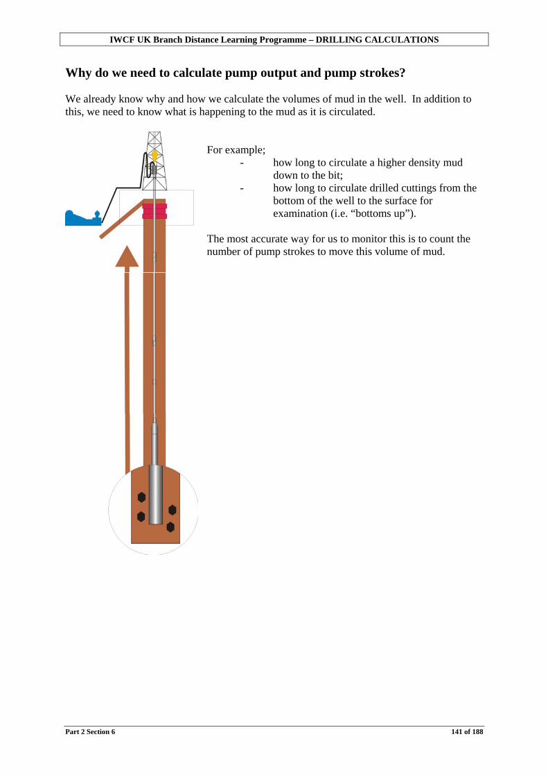
IWCF UK Branch Distance Learning Programme – DRILLING CALCULATIONS
Part 2 Section 6 141 of 188
Why do we need to calculate pump output and pump strokes? We already know why and how we calculate the volumes of mud in the well. In addition to this, we need to know what is happening to the mud as it is circulated.
For example;
- how long to circulate a higher density mud down to the bit;
- how long to circulate drilled cuttings from the bottom of the well to the surface for examination (i.e. “bottoms up”).
The most accurate way for us to monitor this is to count the number of pump strokes to move this volume of mud.

IWCF UK Branch Distance Learning Programme – DRILLING CALCULATIONS
Part 2 Section 6 142 of 188
To calculate the number of strokes to pump a volume of mud we must divide the volume in barrels by the pump output in barrels per stroke.
The formula Strokes =
e)(bbl/strokoutput pump(bbl) pump tovolume
Try some yourself . . . Exercise 2.37 Calculate the number of strokes for the following (answer to the nearest stroke); 1. Volume to pump = 129.3 bbl Pump output = 0.119 bbl/stroke 2. Volume to pump = 156.8 bbl Pump output = 0.109 bbl/stroke 3. Volume to pump = 1043.7 bbl Pump output = 0.158 bbl/stroke 4. Volume to pump = 83.5 bbl Pump output = 0.12 bbl/stroke 5. Volume to pump = 652.4 bbl Pump output = 0.072 bbl/stroke
Example
Annular volume = 1,000 bbl Pump output = 0.1 bbl/stroke
How many pump strokes are needed to circulate the cuttings from the bottom of the well to surface? If the pump output is 0.1 bbl/stroke, the number of strokes to pump 1,000 bbl will be; = 1.0000,1 ÷ = 10,000 strokes

IWCF UK Branch Distance Learning Programme – DRILLING CALCULATIONS
Part 2 Section 6 143 of 188
Time Whilst monitoring the number of pump strokes required to pump a volume of mud is the most accurate, it may also be useful to know how long this operation might take. The time will depend on how fast the pump is running. This is known as the pump rate and is measured in strokes per minute (spm). Time calculations will only work for a constant pump rate.
Example How long will it take to pump 10,000 strokes at 50 spm?
Time = rate pumpstrokes ofnumber
= 50000,10
= 200 minutes (3 hours 20 minutes)
The formula Time (mins) =
(spm) rate pump pump tostrokes
Try some yourself . . . Exercise 2.38 Calculate the time for (answer to nearest minute); 1. 12,000 strokes at 200 spm 2. 950 strokes at 30 spm 3. 1,192 strokes at 40 spm 4. 1,548 strokes at 20 spm 5. 1,190 strokes at 150 spm

IWCF UK Branch Distance Learning Programme – DRILLING CALCULATIONS
Part 2 Section 6 144 of 188
Now putting both together . . .
Drill string capacity = 196.2 bbl Annular volume = 792.6 bbl
Pump output = 0.109 bbl/stroke Pump rate = 30 spm
Calculate the following; a) Strokes to displace the drill string (i.e. pump mud from surface to the bit).
Strokes = e)(bbl/strokoutput pump
(bbl) pump tovolume
= 109.0
2.196
= 1,800 strokes b) Time to displace the drill string (surface to bit)
Time (mins) = (spm) rate pumppump tostrokes
= 30
1,800
= 60 minutes

IWCF UK Branch Distance Learning Programme – DRILLING CALCULATIONS
Part 2 Section 6 145 of 188
c) Strokes to circulate the annular volume (i.e. to pump mud from the bottom of the well to surface or “bottoms up”).
Strokes = e)(bbl/strokoutput pump
(bbl) pump tovolume
= 0.109792.6
= 7,272 strokes
d) Time to circulate “bottoms up”.
Time = (spm) rate pumppump tostrokes
= 30
7,272
= 242 minutes
e) Strokes for a complete (Total) circulation of the well.
Total circulation = drill string strokes + annular strokes = 1,800 + 7,272 = 9,072 strokes
Try some yourself . . . Exercise 2.39
Drill string capacity = 150.8 bbl Annular volume = 1074.8 bbl
Pump output = 0.119 bbl/stroke Pump rate = 40 spm
Calculate: 1. The strokes to pump from surface to bit. 2. The time to pump from surface to bit. 3. The strokes to pump from bit to surface (“bottoms up”). 4. The time to pump from bit to surface (“bottoms up”). 5. The strokes for a complete circulation of the well.
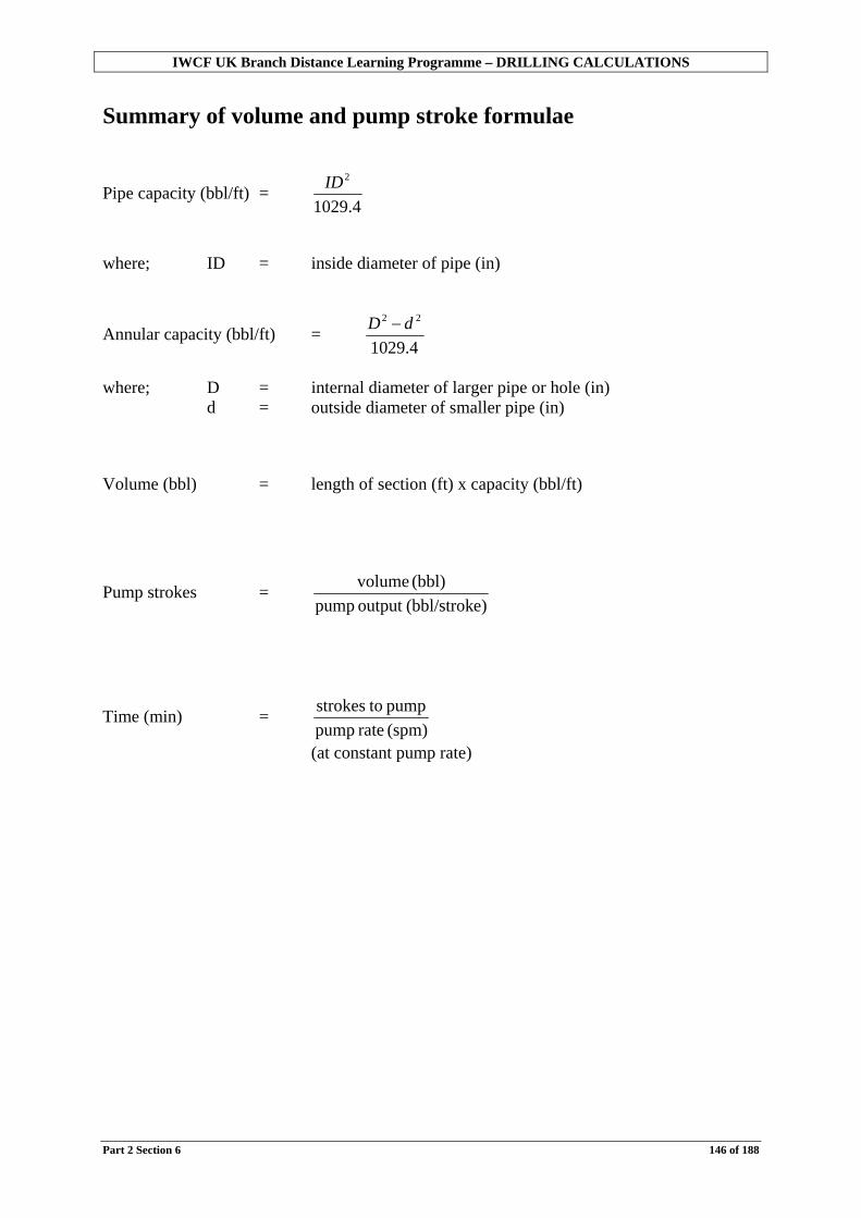
IWCF UK Branch Distance Learning Programme – DRILLING CALCULATIONS
Part 2 Section 6 146 of 188
Summary of volume and pump stroke formulae
Pipe capacity (bbl/ft) = 4.1029
2ID
where; ID = inside diameter of pipe (in)
Annular capacity (bbl/ft) = 4.1029
22 dD −
where; D = internal diameter of larger pipe or hole (in) d = outside diameter of smaller pipe (in) Volume (bbl) = length of section (ft) x capacity (bbl/ft)
Pump strokes = e)(bbl/strokoutput pump
(bbl) volume
Time (min) = (spm) rate pumppump tostrokes
(at constant pump rate)

IWCF UK Branch Distance Learning Programme – DRILLING CALCULATIONS
Part 2 Section 6 147 of 188
Try some yourself . . . Exercise 2.40 Putting together the calculations in sections 4, 5 and 6 try the following exercise. Using the following information;
Well data Hole dimensions Depth 9,875 ft 95/8 in casing shoe 7,990 ft Hole size 81/2 in Internal capacities 61/2 in drill collars (length 600 ft) 0.00768 bbl/ft 5 in HWDP (length 500 ft) 0.0088 bbl/ft 5 in drill pipe 0.01776 bbl/ft Annular capacities Drill collars in open hole 0.0292 bbl/ft Drill pipe/HWDP in open hole 0.0459 bbl/ft Drill pipe in 95/8 in casing 0.0505 bbl/ft Pump details Pump output 0.119 bbl/stroke Calculate:
1. Drill string capacity (bbl) 2. Annular volume (bbl) 3. Total well volume (bbl) 4. Strokes to circulate from surface to bit. 5. Strokes to circulate from bit to surface 6. Strokes for a complete circulation of the well 7. Time for a complete circulation of the well at 30 spm

IWCF UK Branch Distance Learning Programme – DRILLING CALCULATIONS
Part 2 Section 6 148 of 188
This page is deliberately blank

IWCF UK Branch Distance Learning Programme – DRILLING CALCULATIONS
Part 2 Section 7 149 of 188
Section 7: Volume and Pump Stroke Calculations using a Kill Sheet
So far when calculating volumes and pump strokes for a well we have drawn a picture of the well ourselves and recorded the information on a blank sheet of paper. Usually rigs or companies have special forms for helping us to calculate and record this information when we are in a well control situation. These forms are called “kill sheets”. In this section we will introduce the IWCF kill sheet and show how to fill in some parts of it. Objectives
• To introduce part of the IWCF kill sheet. • To use the kill sheet to calculate volumes and pump strokes.
Try this first…Exercise 2.41 Given the following well information:
Well data Hole dimensions
Depth 9,800 ft 95/8 in casing shoe 7,950 ft Hole size 81/2 in
Internal capacities 61/2 in drill collars (length 600 ft) 0.00768 bbl/ft 5 in HWDP (length 500 ft) 0.0088 bbl/ft 5 in drill pipe 0.01776 bbl/ft
Annular capacities Open hole/drill collar 0.0292 bbl/ft
Open hole/drill pipe 0.0459 bbl/ft Casing/drill pipe 0.0505 bbl/ft Pump details
Pump output 0.119 bbl/stroke Slow pump rate 40 spm
Calculate: 1. The pump strokes required to circulate mud down the drill string (i.e. surface to the
bit). 2. The pump strokes required to circulate mud up the annulus (i.e. bit to surface). 3. The pump strokes required for a complete circulation. 4. The time required for a complete circulation at 30 strokes per minute.
?

IWCF UK Branch Distance Learning Programme – DRILLING CALCULATIONS
Part 2 Section 7 150 of 188
During well control operations (discussed in Part 3) it is vitally important that we monitor the well closely. This includes:
- Mud density - Pressures - Volumes and pump strokes
To assist us we fill out a kill sheet. Density and pressure calculations will be discussed in Part 3, but volume and strokes we can already calculate. Lets look at the first page of an IWCF kill sheet.
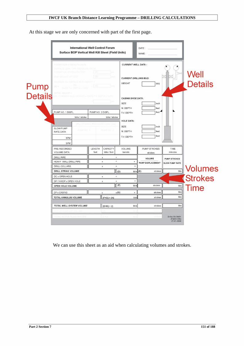
IWCF UK Branch Distance Learning Programme – DRILLING CALCULATIONS
Part 2 Section 7 151 of 188
At this stage we are only concerned with part of the first page.
We can use this sheet as an aid when calculating volumes and strokes.
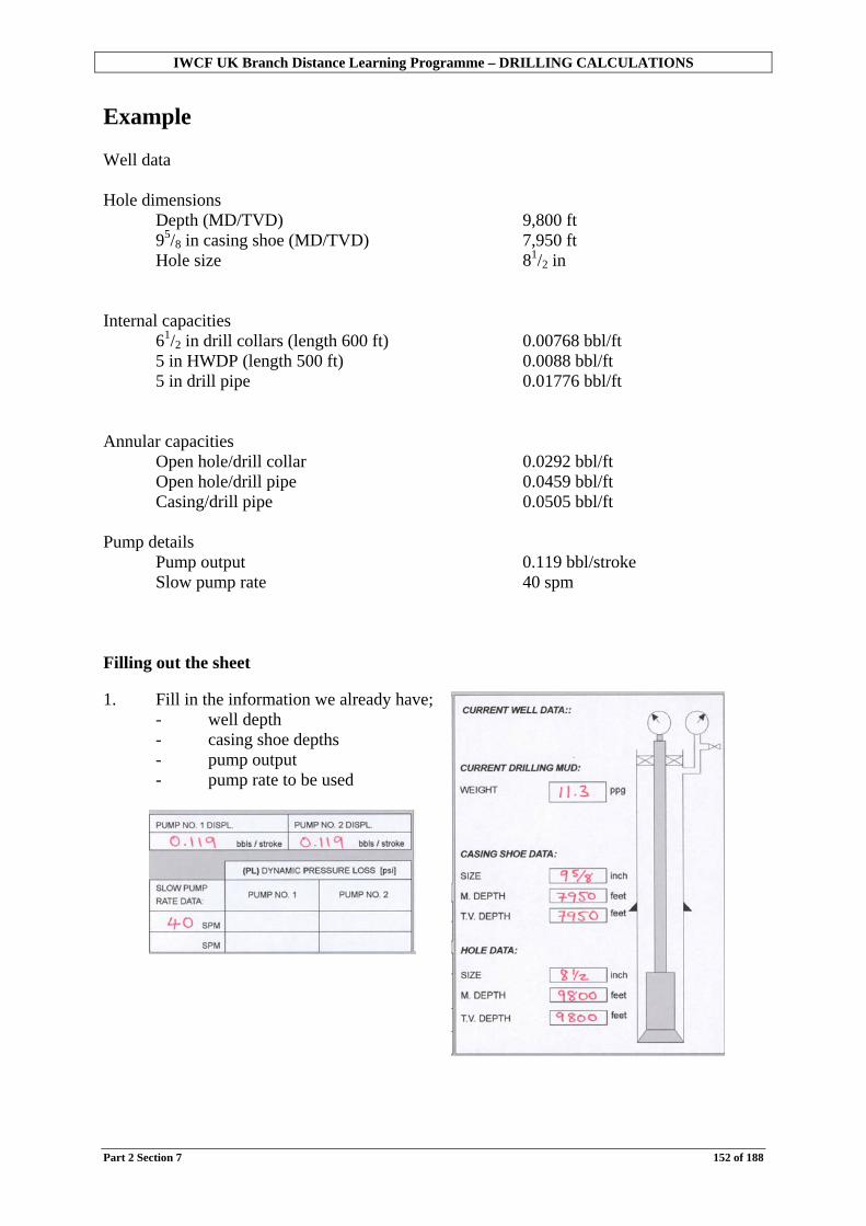
IWCF UK Branch Distance Learning Programme – DRILLING CALCULATIONS
Part 2 Section 7 152 of 188
Example Well data Hole dimensions Depth (MD/TVD) 9,800 ft 95/8 in casing shoe (MD/TVD) 7,950 ft Hole size 81/2 in Internal capacities 61/2 in drill collars (length 600 ft) 0.00768 bbl/ft 5 in HWDP (length 500 ft) 0.0088 bbl/ft 5 in drill pipe 0.01776 bbl/ft Annular capacities Open hole/drill collar 0.0292 bbl/ft
Open hole/drill pipe 0.0459 bbl/ft Casing/drill pipe 0.0505 bbl/ft
Pump details Pump output 0.119 bbl/stroke
Slow pump rate 40 spm Filling out the sheet 1. Fill in the information we already have;
- well depth - casing shoe depths - pump output - pump rate to be used
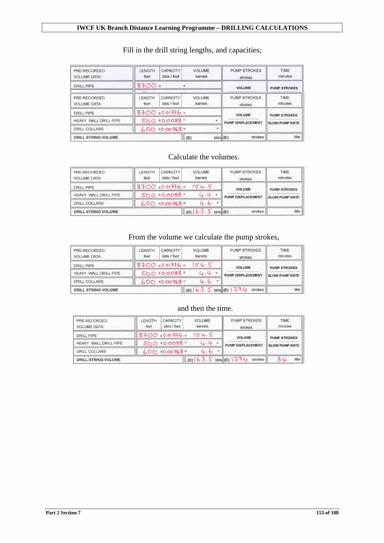
IWCF UK Branch Distance Learning Programme – DRILLING CALCULATIONS
Part 2 Section 7 153 of 188
Fill in the drill string lengths, and capacities;
Calculate the volumes.
From the volume we calculate the pump strokes,
and then the time.

IWCF UK Branch Distance Learning Programme – DRILLING CALCULATIONS
Part 2 Section 7 154 of 188
2. Fill in the lengths for the different sections of annulus. Calculate the volumes, strokes and time. Note: On a kill sheet the annulus volume is usually calculated in two parts;
- open hole volume - total annular volume
The reason for this will be discussed in Part 3.
Firstly the lengths of the open hole section;
Then the annular capacities; Calculate the volumes,
then the strokes and time.
Next the casing annular volume,
then the strokes and time. Finally add the open hole annular volume and the casing annular volume to get the total annulus volume.
Complete the Total Well System Volume (i.e. the total amount of mud in the well). This is the sum of

IWCF UK Branch Distance Learning Programme – DRILLING CALCULATIONS
Part 2 Section 7 155 of 188

IWCF UK Branch Distance Learning Programme – DRILLING CALCULATIONS
Part 2 Section 7 156 of 188
The finished data sheet:
This is as far as we need to go at this stage. Completing the rest of the sheet will be done in Part 3.

IWCF UK Branch Distance Learning Programme – DRILLING CALCULATIONS
Part 2 Section 7 157 of 188
A word about depths You may have noticed that on the kill sheet there are two boxes for casing shoe depth and for hole depth. They are for:
Measured depth (MD) True vertical depth (TVD)
Why two depths?
If a well is vertical, the measured depth is the same as the vertical depth. That is, the measured length of the pipe or hole is the same as the vertical depth of the well.
If a well is not vertical (we use the term deviated), the measured length of the pipe or hole is greater than the vertical depth of the well. Imagine a barrel of rig wash.
The volume of the barrel is exactly the same whether it stands on end or is lying on its side. Its vertical height changes, but its volume does not.

IWCF UK Branch Distance Learning Programme – DRILLING CALCULATIONS
Part 2 Section 7 158 of 188
When calculating volumes it is important to use the measured depths – it is the actual length of pipe that is important. True vertical depths are used when calculating pressures and related calculations – this will be dealt with further in Part 3. When only one depth is given, such as the examples we have done so far, the well is vertical and MD and TVD are the same.
Remember For volume calculations use MEASURED DEPTHS.

IWCF UK Branch Distance Learning Programme – DRILLING CALCULATIONS
Part 2 Section 7 159 of 188
Try one yourself . . . Exercise 2.42 Using the following well data, complete the relevant parts of a kill sheet and answer the questions. (A blank sheet is included at the end of this section).
Well data Hole dimensions Depth 8,980 ft 133/8 in casing shoe 6,015 ft Hole size 121/2 in Internal capacities 8 in drill collars (length 750 ft) 0.0077 bbl/ft 5 in HWDP (length 650 ft) 0.0088 bbl/ft 5 in drill pipe 0.01776 bbl/ft Annular capacities Drill collars in open hole 0.0836 bbl/ft
Drill pipe/HWDP in open hole 0.1215 bbl/ft Drill pipe in casing 0.1521 bbl/ft
Pump details Pump output 0.12 bbl/stroke
Pump rate 30 spm Calculate; 1. Strokes to displace the drill string. 2. Time to displace the drill string at 30 spm. 3. Total annulus volume (bbl). 4. Total well system volume (bbl). 5. Time to circulate the total well system volume at 30 spm.

IWCF UK Branch Distance Learning Programme – DRILLING CALCULATIONS
Part 2 Section 7 160 of 188

IWCF UK Branch Distance Learning Programme – DRILLING CALCULATIONS
Part 2 Section 8 161 of 188
Section 8: Trip Monitoring Calculations In previous sections we have calculated mud volumes in a well and looked at the use of a kill sheet for well control operations. A very critical part of drilling operations takes place when we trip. In this section we will discuss tripping and why mud monitoring is critical. We will also show how to perform the various calculations required to allow us to monitor trips. To make monitoring of trips easier and more accurate, we use a trip sheet, this will be discussed in this section, as will be what happens when we pump a slug. Objectives
• To discuss why trips should be monitored. • To discuss what should be monitored. • To describe the calculations required to allow us to monitor trips. • To describe the use of trip sheets. • To describe the procedure and calculations for pumping a slug.
Try this first…Exercise 2.43
Well data 12¼ in hole to 10,550 ft Drill string 5 in drill pipe (ID 4.276 in, wt. 20.9 lb/ft) 8 in drill collars (ID 213/16 in, wt. 150 lb/ft) Length 850 ft Drill pipe metal displacement 0.0076 bbl/ft Drill collar metal displacement 0.055 bbl/ft Calculate the volume of mud required to fill the hole if the entire string is tripped out dry.
?

IWCF UK Branch Distance Learning Programme – DRILLING CALCULATIONS
Part 2 Section 8 162 of 188
Firstly, what is a trip? In previous sections we discussed the drilling of a well section by section. A particular section, say the 121/4 in hole section (drilled with a 121/4 in bit), will not always be drilled with one bit. Several bits may be required. The reasons for this may be;
- the bit wears out before the section is complete; - a different bit is required to drill a different formation.
In either case, and at the end of the section, the whole drill string must be pulled out to bring the bit to surface and either put on a new bit or carry out some other operation such as running casing.
This operation of pulling pipe out of the well or running pipe into the well is known as tripping. A complete trip from bit on bottom, to surface and back to bottom is a “round trip”.

IWCF UK Branch Distance Learning Programme – DRILLING CALCULATIONS
Part 2 Section 8 163 of 188
Why monitor trips? Imagine a bath half full of water
What happens to the level of the water when you get into the bath? It rises (it may even overflow). What happens to the water as you get out of the bath?
The level returns back to its initial level (assuming no overflow). The same thing will happen when the drill string is removed from the hole – if no action is taken the mud level in the well bore will fall. Bit on bottom, hole full of mud. Bit out of the hole, mud level has fallen So why is this drop in mud level when the string is pulled out important?

IWCF UK Branch Distance Learning Programme – DRILLING CALCULATIONS
Part 2 Section 8 164 of 188
One of the functions of drilling fluid (or mud) is to exert a pressure to balance that in the formation. This hydrostatic pressure depends on the mud density (weight) and the height of the fluid column. (Hydrostatic pressure will be discussed fully in Part 3). If the level of the mud in the hole is allowed to fall, there will be a corresponding drop in the hydrostatic pressure. This drop in hydrostatic pressure may cause the well to become out of control and may result in a blowout (although this is rare). It is important then that as the string is tripped out the hole is kept full of drilling fluid. It is not however quite as simple as just keeping the hole full. We must make sure we replace the volume of pipe removed with the correct volume of drilling mud. Imagine a measuring cylinder with a pencil inside.
The volume of the pencil is 1 in3.
What will happen to the level of the water if the pencil is removed?
The level will drop. How much water will need to be added to top up the cylinder? A volume of water equal to that of the pencil (1 in3) must be added. If more needs to be added then perhaps some water has spilt. If less needs to be added then there is a mistake in the calculation. The same thing applies when tripping pipe.

IWCF UK Branch Distance Learning Programme – DRILLING CALCULATIONS
Part 2 Section 8 165 of 188
Example – Tripping into the hole
If we run in 1stand of pipe with a volume of 2 barrels, we should get 2 barrels of mud out of the hole.
If we get back too much we have gained some fluid (possibly from the formation).
If we get too little mud back then we have lost fluid (this could be a leak or a loss into the formation).

IWCF UK Branch Distance Learning Programme – DRILLING CALCULATIONS
Part 2 Section 8 166 of 188
Example – Tripping out of the hole
If we pull one stand of pipe with a volume of 2 barrels out of the hole, to keep the hole full, we should put in 2 barrels of mud.
If we have to put in more than 2 barrels of mud then we must be losing mud somewhere on surface or downhole.
If we have to put in less than 2 barrels of mud then we must be gaining fluid from somewhere, possibly from the formation.
To maintain the balance between drilling fluid hydrostatic and formation pressure, it is vitally important that the hole is kept full with the correct amount of drilling fluid. Any discrepancy must be investigated.
The correct procedures for this will be discussed fully in Part 3.

IWCF UK Branch Distance Learning Programme – DRILLING CALCULATIONS
Part 2 Section 8 167 of 188
Try some yourself . . . Exercise 2.44 1. When tripping out you pull 5 stands of pipe from the hole. Each stand has a
volume of 2.2 barrels. It takes only 5 barrels to fill the hole. Are you:
a. gaining fluid from somewhere; or b. losing fluid from somewhere?
2. When tripping into the hole you run in 5 stands. Each stand has a volume of 5 barrels. Only 20 barrels of mud are returned from the well. Are you:
a. gaining; or b. losing?
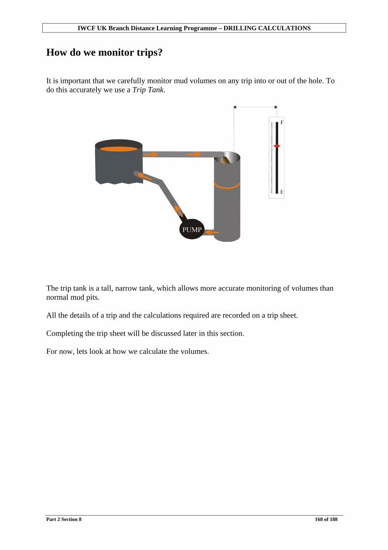
IWCF UK Branch Distance Learning Programme – DRILLING CALCULATIONS
Part 2 Section 8 168 of 188
How do we monitor trips? It is important that we carefully monitor mud volumes on any trip into or out of the hole. To do this accurately we use a Trip Tank. The trip tank is a tall, narrow tank, which allows more accurate monitoring of volumes than normal mud pits. All the details of a trip and the calculations required are recorded on a trip sheet. Completing the trip sheet will be discussed later in this section. For now, lets look at how we calculate the volumes.

IWCF UK Branch Distance Learning Programme – DRILLING CALCULATIONS
Part 2 Section 8 169 of 188
Calculating trip volumes What do we need to calculate?
The volume of the pipe removed from or run into the hole.
This is best done on a per foot basis, i.e. how many barrels in each foot of pipe. First we will take the example of tripping “dry” pipe.
Dry pipe When pipe is pulled “dry” we are only removing the metal of the pipe from the well, i.e. the mud inside the pipe drains through the pipe back into the well.
Dry pipe = metal displacement (steel)
Wet pipe When pipe is pulled “wet” we are removing both the metal of the pipe and the mud inside (e.g. when the string or bit is plugged).
Wet pipe = metal displacement + capacity

IWCF UK Branch Distance Learning Programme – DRILLING CALCULATIONS
Part 2 Section 8 170 of 188
Calculating metal displacements What is the volume of metal in 1 foot of pipe? We can calculate this using the same formula used to calculate annular volumes with a minor change.
Metal displacement
Metal displacement (bbl/ft) = 4.1029
22 dD −
D = outside diameter of the pipe (inches) d = inside diameter of the pipe (inches) Note that D and d refer to different dimensions in this case compared to when we calculate annular volumes – refer back to Part 2 Section 3.
Example OD of pipe = 5 in ID of pipe = 4.276 in
Volume of metal = 4.1029
22 dD −
= 4.1029
276.45 22 −
= 0.0065 bbl/ft (to 4 decimal places)

IWCF UK Branch Distance Learning Programme – DRILLING CALCULATIONS
Part 2 Section 8 171 of 188
We should now be able to calculate the total metal displacement for any length of pipe.
Try some yourself . . . Exercise 2.45 Calculate (using the above method) the metal displacement or volume of metal in bbl/ft for the following; (answers to 4 decimal places) OD
(in) ID (in)
Metal displacement (bbl/ft)
1
31/2
2.764
2
5
4.214
3
5
3
4
4
3.34
5
65/8
5.965
6
133/8
12.415
Example 5 inch drill pipe (ID 4.276 inches) has a metal displacement of 0.0065 barrels per foot. What would be the metal displacement of 1,000 feet of pipe? Total metal displacement (bbl) = Metal displacement (bbl/ft) x Length (ft) = 0.0065 x 1,000 = 0.65 bbl

IWCF UK Branch Distance Learning Programme – DRILLING CALCULATIONS
Part 2 Section 8 172 of 188
Try some yourself …. Exercise 2.46 Calculate the following metal displacements in barrels; Metal displacement
bbl/ft Length of pipe
feet Total metal displacement
bbl 1 0.0155 1,200 2 0.0545 850 3 0.0045 7,050 4 0.079 500 5 0.0087 5,450

IWCF UK Branch Distance Learning Programme – DRILLING CALCULATIONS
Part 2 Section 8 173 of 188
By adding the lengths of pipe, we can now calculate the metal displacement of the whole string.
Example The drill string consists of; 9,000 ft if 5 in drill pipe (ID 4.276 in) 1,000 ft of 8 in drill collars (ID 3 in) Calculate the volume of drilling fluid required to fill the hole if the entire string is tripped out dry. Drill pipe
Metal displacement (bbl/ft) = 4.1029
22 dD −
= 4.1029
276.45 22 −
= 0.0065 bbl/ft Volume (bbl) = length x metal displacement = 9,000 x 0.0065 = 58.5 bbl Drill collars
Metal displacement (bbl/ft) = 4.1029
22 dD −
= 4.1029
38 22 −
= 0.053 bbl/ft Volume (bbl) = length x metal displacement = 1,000 x 0.053 = 53.0 bbl Total volume of metal removed = drill pipe + drill collars = 58.5 + 53.0 = 111.5 bbl Drilling fluid required to fill the hole = 111.5 bbl The drilling fluid required to fill the hole should be the same as the volume of metal removed.

IWCF UK Branch Distance Learning Programme – DRILLING CALCULATIONS
Part 2 Section 8 174 of 188
Something to consider This method can be used for straight-sided pipes such as drill collars and casing, but does not take into account the tool joints on drill pipe. An easy way to deal with this is to use tables provided by various companies which give metal displacements taking the tool joints into account.
Wherever possible, use accurate metal displacements which take into account the tool joints.
Example Calculated metal displacement of 5 in drill pipe (ID 4.276 in) = 0.0065 bbl/ft Metal displacement from tables (including tool joints) = 0.0071 bbl/ft What difference will this make over 10 stands (each of 93 feet)? Calculated volume = 10 x 93 x 0.0065 = 6.045 bbl Volume using tables = 10 x 93 x 0.0071 = 6.603 bbl That is a difference of over 0.5 barrels for 10 stands.
Try some yourself . . . Exercise 2.47 Calculate the volume of mud (bbl) required to fill the hole when the following strings of pipe are pulled out of the hole. 1. Drill string of
5 in drill pipe (ID 4.276 in) 8,250 ft 6 in drill collars (ID 2.5 in) 930 ft
2. Drill string of 5 in drill pipe (ID 4.214 in) 6,275 ft 5 in HWDP (ID 3 in) 560 ft 8 in drill collars (ID 2.75 in) 651 ft

IWCF UK Branch Distance Learning Programme – DRILLING CALCULATIONS
Part 2 Section 8 175 of 188
Pipe displacements for “wet” pipe (Closed end displacements)
When pulling wet pipe we must also take into account that we are removing both the metal and the volume of mud inside. This can happen when flow through the pipe is restricted because of tools in the string (Measurement While Drilling tools, motors etc.) or if the string is blocked (plugged). This is known as the closed end displacement. Closed end displacement (bbl/ft) = metal displacement (bbl/ft) + capacity (bbl/ft) There are several methods to calculate closed end displacement.
Remember Dry pipe = removing (or adding) metal displacement only Wet pipe = removing (or adding) metal displacement plus capacity (the mud inside the pipe)

IWCF UK Branch Distance Learning Programme – DRILLING CALCULATIONS
Part 2 Section 8 176 of 188
Closed end displacements In this method we will simply calculate the volume of the solid (closed end) pipe. To do this we will use only the OD of the pipe. Note that this method does not take into account tool joints.
This method will allow us to calculate accurate closed end displacements for straight-sided pipes (e.g. drill collars or casing) but does not allow for tool joints on drill pipe.
Closed end displacements
Closed end displacement = 4.1029
2OD
OD = outside diameter of the pipe in inches
Example – Closed end displacements 1. Calculate the closed end displacement (bbl/ft) of 8 in (147 lb/ft) drill collars (ID 3
in).
Closed end displacement = 4.1029
2OD
= 28
1029.4
= 0.0622 bbl/ft
Example – Closed end displacements 2. Calculate the closed end displacement (bbl/ft) of 5 in (19.5 lb/ft) drill pipe (ID 4.276
in) (grade S).
Closed end displacement = 4.1029
2OD
= 4.1029
52
= 0.0243 bbl/ft

IWCF UK Branch Distance Learning Programme – DRILLING CALCULATIONS
Part 2 Section 8 177 of 188
This method will allow us to calculate accurate closed end displacements for straight-sided pipes (e.g. drill collars or casing) but does not allow for tool joints on drill pipe.
Try some yourself . . . Exercise 2.48 Calculate the following using the above method; OD (in) Closed end displacement (bbl/ft) 1
5
2
51/2
3
61/4
4
91/2
5
95/8

IWCF UK Branch Distance Learning Programme – DRILLING CALCULATIONS
Part 2 Section 8 178 of 188
Using a trip sheet
Most companies have a standard, pre-printed form for monitoring trips.
On the top of the sheet are usually details of pipe displacements and capacities. Abbreviations: DC1 = Drill collar size 1 DC2 = Drill collar size 2 HWDP = Heavyweight drill pipe DP1 = Drill pipe size 1 DP2 = Drill pipe size 2 As the pipe is pulled or run in stands it is normal to calculate displacements firstly “per foot” and then “per stand” based on an average stand length. Also included is the total volume for each section. As we pull or run pipe we will measure the actual hole fill or displacement and record the “Measured Hole Fill” column. These figures come from monitoring the trip tank.

IWCF UK Branch Distance Learning Programme – DRILLING CALCULATIONS
Part 2 Section 8 179 of 188
Example – pulling out of the hole In this example we have assumed an average stand length of 93 feet. With this information we can now fill in the top of the sheet.
Column 1 shows the stand numbers as they are pulled starting with zero.

IWCF UK Branch Distance Learning Programme – DRILLING CALCULATIONS
Part 2 Section 8 180 of 188
We normally monitor every 5 stands for drill pipe and every stand for the BHA (drill collars and HWDP) because of their large displacements). Column 2 shows the initial volume of mud in the trip tank. (40 bbl) Column 3 shows the calculated hole fill – in this case 3.5 bbl per 5 stands for drill pipe. (Displacement per stand = 0.7 bbl) After each 5 stands we will complete the next line. For example, after stand 5 the trip tank has dropped to 36.5 bbl. After stand 5 The measured hole fill is the drop in the trip tank (40 – 36.5 = 3.5 bbl). This is put in column 4. The total hole fill is in column 5. As this is the same as the calculated there is no discrepancy – all is as it should be.

IWCF UK Branch Distance Learning Programme – DRILLING CALCULATIONS
Part 2 Section 8 181 of 188
After 10 stands The trip tank is 33 bbl.
Note column 5 is showing the accumulated hole fill which is now 7 bbl, again matching the calculated hole fill in column 2.

IWCF UK Branch Distance Learning Programme – DRILLING CALCULATIONS
Part 2 Section 8 182 of 188
Lets complete up to stand 20 assuming everything has gone well (i.e. there is no discrepancy between calculated and actual hole fill).

IWCF UK Branch Distance Learning Programme – DRILLING CALCULATIONS
Part 2 Section 8 183 of 188
After stand 25 Trip tank is 24 bbl.
Completing the line shows we have a discrepancy of 1.5 bbl, it has taken less mud to fill the hole than calculated. This gain must be investigated as it could indicate fluid coming into the well from the formation.
A word about the BHA If we examine the displacements for 5 stands for the different pipe in the well we see; 5 in drill pipe 3.5 bbl/5 stands 5 in HWDP 8.5 bbl/5 stands 8 in drill collars 25.0 bbl/5 stands Because of the larger volumes concerned in the BHA it is normal to monitor the hole for each stand. Hole fill when pulling the BHA is critical.

IWCF UK Branch Distance Learning Programme – DRILLING CALCULATIONS
Part 2 Section 8 184 of 188
Interpretation of trip sheets It is easy to say investigate every deviation from calculated figures, and of course this is exactly what should happen. What exactly do we mean by a discrepancy – 0.1 bbl, 0.5 bbl, 1.0 bbl? Sometimes our calculations may not be entirely accurate (e.g. not allowing for tool joints). However in the field, this level of accuracy is acceptable. So whilst we must investigate any discrepancies, we must be aware of the general trend. For example, your calculations may give a hole fill of 3.5 bbl/stand. If on every trip out and trip in on the well we record a displacement of 3.25 bbl/stand with no further happening then obviously this is the norm. On subsequent trips we would regard 3.25 bbl/stand as the norm and investigate any discrepancy from this. It is important to be aware of the normal trend and investigate any deviation from this. If at any time there is a doubt – CHECK FOR FLOW FROM THE WELL. Filling the trip tank Trip tanks do not have the capacity to fill the hole for a whole trip out (or to take the returns for a whole trip in). They will need to be filled (or emptied) several times during a trip. When the level becomes low, the trip tank is filled from another pit using the “fill pump”, during this time it is not possible to monitor the hole fill. Because of this, tripping should be halted while the trip tank is filled (or emptied). Pumping a slug Prior to some trips, a heavy slug of mud is pumped into the pipe. This drops the level of the mud in the pipe, allowing us to pull dry pipe.

IWCF UK Branch Distance Learning Programme – DRILLING CALCULATIONS
Part 2 Section 8 185 of 188
As the slug settles in the drill pipe, a volume of mud will be returned from the annulus (the volume will be equal to that of the empty pipe). These extra mud returns can make it very difficult, if not impossible, to monitor hole fill correctly. Because of this, tripping should not commence until the well is stable after the slug has settled. These extra returns can be calculated using the following formula (amongst many);
Extra returns from the well =
1density muddensity slug volumeslug ⎟⎟
⎠
⎞⎜⎜⎝
⎛−×
as the slug drops (bbl) slug volume = volume of slug pumped (bbl) slug density = ppg mud density = mud density in the well (ppg) Firstly let us run through the details of pumping a slug Well details Depth = 12,000 ft Mud density = 15 ppg Slug density = 17 ppg Slug volume = 30 bbl Drill pipe capacity = 0.01776 bbl/ft 1. First, the mud pump is lined up to the slug pit.

IWCF UK Branch Distance Learning Programme – DRILLING CALCULATIONS
Part 2 Section 8 186 of 188
2. The 30 bbl slug is pumped from the slug pit into the system. Returns are to the active pit. Active pit will increase by the volume of the slug (30 bbl).
3. The slug is then displaced (chased) completely into the pipe,
pumping from the active returning to the active. No change in volumes.
4. The well is now lined up to be monitored on the trip tank. When the top drive (or kelly) is broken off, the level will drop inside the pipe. The trip tank should rise by a corresponding amount.
Time should be allowed for this to happen prior to starting the trip and any discrepancy investigated.

IWCF UK Branch Distance Learning Programme – DRILLING CALCULATIONS
Part 2 Section 8 187 of 188
Calculating the trip tank increase;
Volume increase (bbl) = ⎟⎟⎠
⎞⎜⎜⎝
⎛−× 1
(ppg)density mud(ppg)density slug (bbl) volumeslug
= ⎟⎠⎞
⎜⎝⎛ −× 1151730
= 4 bbl If all is correct, the trip tank should increase by 4 bbl as the slug drops. We could now calculate the height of the empty pipe.
Height of empty pipe = capacity pipe
pipeempty of volume
Height of empty pipe = height (or length in non-vertical hole) in bbl Volume of empty pipe = bbl Pipe capacity = bbl/ft In our example;
Height of empty pipe = 0.01776
4
= 225.2 ft There should be 225 feet of dry pipe.
IWCF UK Branch Distance Learning Programme – DRILLING CALCULATIONS
Part 2 Section 8 188 of 188
Try some yourself . . . Exercise 2.49
Well details
Depth = 18,500 ft Mud density = 14 ppg Drill pipe capacity = 0.01776 bbl/ft A 35 bbl slug (density = 16 ppg) is pumped from the slug pit then chased with 15 bbl of mud from the active pit. The well is then lined up on the trip tanks and the top drive removed. Calculate; 1. The increase in level in the trip tank as the slug drops. 2. The volume of the empty pipe. 3. The height of the empty pipe.