Embed Size (px)
DESCRIPTION
This paper recapitulates the drilling operation, the main materials used in drilling as well as the important drilling activities. The second part of this paper will be reserved to mud logging activities and their role on the drilling site.
Citation preview
January 2008 Drilling & Mud Logging
1
Ali AZZOUZ MSc Asset Management with Petroleum Economics
Economical Studies Engineer
Sonatrach E_mail : [email protected]
Drilling
&
Mud Logging

January 2008 Drilling & Mud Logging
2
ACKNOWLEDGEMENTS
I would like to acknowledge and express my sincere gratitude to Mrs Salim
BRAHAMI, Toufik BADSI and Mohamed Abderaouf BOUZIDANI for their
availability, effective guidance, and valuable advice. I would like also to
thank them for the information they provided me through discussions.
My thanks also go to Mrs.: CHELGHOUM and AIDOUD for their help and
effective guidance. And my warmest thanks go to all ENAFOR 21 RIG Staff.
With a deep sense of gratitude, I would like to express my thanks to all DML
staff.
January 2008 Drilling & Mud Logging
3
TABLE OF CONTENTS I. INTRODUCTION ……………………………………………………………………………………………… 04
II. GENERALITIES ABOUT DRILLING ………………………………………………………. 05
1. Definition …………………………………………………………………………………………………………. 05
2. Drilling site equipments ……………………………………………………………………………… 06
2.1. Superstructure Equipments ……………………………………………………………………. 06
2.2. Substructure Equipments ………………………………………………………………………… 07
2.3. Drilling Equipments ………………………………………………………………………………….. 07
2.4. Other Equipments …………………………………………………………………………………….. 07
3. Drilling steps …………………………………………………………………………………………………… 08
3.1. Adding drillpipe …………………………………………………………………………………………. 08
3.2. The round trip …………………………………………………………………………………………… 08
3.3. Casing …………………………………………………………………………………………………………. 08
3.4. Installing the wellhead ……………………………………………………………………………. 08
3.5. Completion ………………………………………………………………………………………………… 09
III. MUDLOGGING ……………………………………………………………………………………………… 10
1. Introduction ……………………………………………………………………………………………………. 10
2. Mud Logging Activities ………………………………………………………………………………… 10
2.1. Geological Control ……………………………………………………………………………………. 10
2.2. Mud & Drilling Parameters ……………………………………………………………………… 11
2.3. Gas System ……………………………………………………………………………………………….. 14
3. Role of formation logging in the drilling of a well ……………………………… 15
3.1. Role of Gas Detection Instruments ………………………………………………………. 16
3.1.1. Total Gas ……………………………………………………………………………………………. 16
3.1.2. Chromatographic Analysis ……………………………………………………………… 16
3.1.3. Hydrogen Sulphide …………………………………………………………………………… 16
3.1.4. Carbon Dioxide …………………………………………………………………………………. 16
3.2. Role of Mud Monitoring Instruments ……………………………………………………. 16
3.2.1. Mud Pit Levels …………………………………………………………………………………… 16
3.2.2. Mud Temperature ……………………………………………………………………………… 16
3.2.3. Mud Weight ……………………………………………………………………………………… 16
3.2.4. Pump Stroke Counter ……………………………………………………………………… 16
3.2.5. Mud Flow ……………………………………………………………………………………………. 17
3.2.6. Mud Resistivity and Chloride Content …………………………………………… 17
3.2.7. Alarm Systems …………………………………………………………………………………. 17
3.2.8. Trip Tanks …………………………………………………………………………………………… 17
3.3. Role of Drilling Monitoring Instruments ………………………………………………… 17
3.3.1. Rate Of Penetration (ROP) ……………………………………………………………… 17
3.3.2. Rotary RPM ………………………………………………………………………………………… 18
3.3.3. Hook load / Weight on bit ………………………………………………………………. 18
3.3.4. Standpipe or Pump Pressure …………………………………………………………. 18
3.3.5. Rotary Torque …………………………………………………………………………………… 19
IV. CONCLUSION ………………………………………………………………………………………………… 19
V. BIBLIOGRAPHY ……………………………………………………………………………………………… 20
January 2008 Drilling & Mud Logging
4
I. INTRODUCTION
Drilling is among the most important and risky activities in the petroleum industry.
It requires many heavy materials and qualified people to be cost effective and
realised on the time required safely and within budget.
One of the important safety instruments in drilling is the mud logging unit which
assists in real time the drilling operation and react for any potential or actual
hazards.
This paper will recapitulate the drilling operation, the main materials used in drilling
as well as the important drilling activities. The second part of this paper will be
reserved to mud logging activities and there role on the drilling site.

January 2008 Drilling & Mud Logging
5
II. GENERALITIES ABOUT DRILLING
1. Definition
Drilling means to make a hole in order to get access to the earth’s subsurface. Many
techniques were developed to prove the existence of hydrocarbons on the earth’s
subsurface, but drilling is still the only technique that can 100% confirm the
existence of hydrocarbons. There are generally two types of drilling, exploration and
production. Exploratory or appraisal wells are aimed to determine the extent of the
reservoir, whereas production or development wells are made for the purpose of
extracting hydrocarbons.
Rotary drilling is the most used nowadays because of its high performance and it
requires heavy materials as shown on the figure below.
January 2008 Drilling & Mud
Logging
6
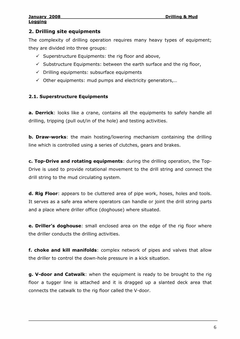
2. Drilling site equipments
The complexity of drilling operation requires many heavy types of equipment;
they are divided into three groups:
� Superstructure Equipments: the rig floor and above,
� Substructure Equipments: between the earth surface and the rig floor,
� Drilling equipments: subsurface equipments
� Other equipments: mud pumps and electricity generators,…
2.1. Superstructure Equipments
a. Derrick: looks like a crane, contains all the equipments to safely handle all
drilling, tripping (pull out/in of the hole) and testing activities.
b. Draw-works: the main hosting/lowering mechanism containing the drilling
line which is controlled using a series of clutches, gears and brakes.
c. Top-Drive and rotating equipments: during the drilling operation, the Top-
Drive is used to provide rotational movement to the drill string and connect the
drill string to the mud circulating system.
d. Rig Floor: appears to be cluttered area of pipe work, hoses, holes and tools.
It serves as a safe area where operators can handle or joint the drill string parts
and a place where driller office (doghouse) where situated.
e. Driller’s doghouse: small enclosed area on the edge of the rig floor where
the driller conducts the drilling activities.
f. choke and kill manifolds: complex network of pipes and valves that allow
the driller to control the down-hole pressure in a kick situation.
g. V-door and Catwalk: when the equipment is ready to be brought to the rig
floor a tugger line is attached and it is dragged up a slanted deck area that
connects the catwalk to the rig floor called the V-door.
January 2008 Drilling & Mud
Logging
7
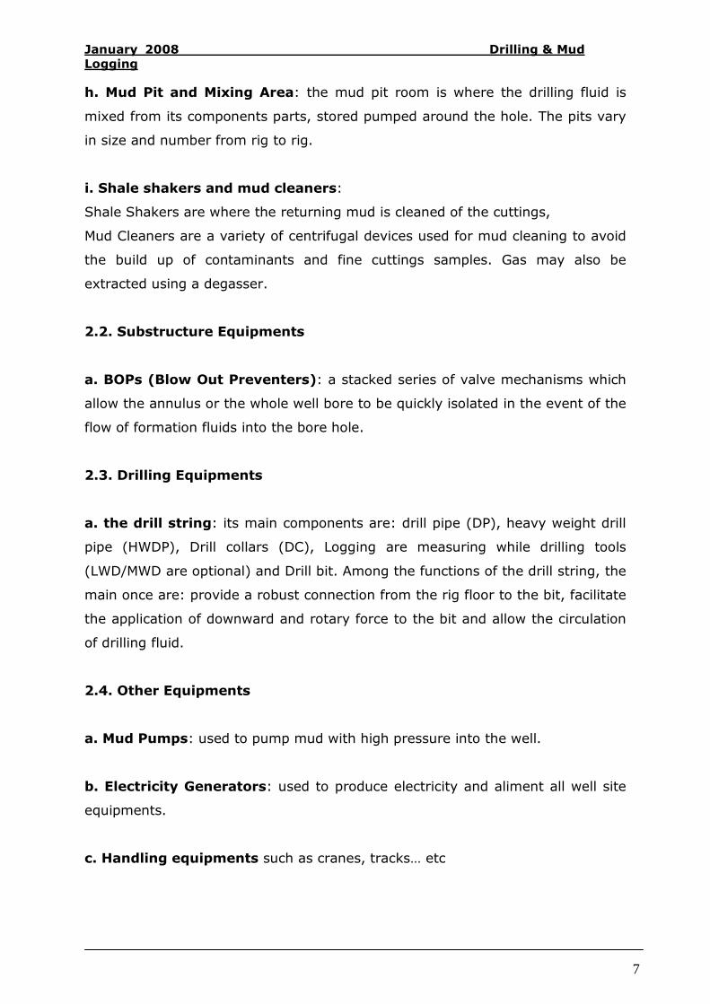
h. Mud Pit and Mixing Area: the mud pit room is where the drilling fluid is
mixed from its components parts, stored pumped around the hole. The pits vary
in size and number from rig to rig.
i. Shale shakers and mud cleaners:
Shale Shakers are where the returning mud is cleaned of the cuttings,
Mud Cleaners are a variety of centrifugal devices used for mud cleaning to avoid
the build up of contaminants and fine cuttings samples. Gas may also be
extracted using a degasser.
2.2. Substructure Equipments
a. BOPs (Blow Out Preventers): a stacked series of valve mechanisms which
allow the annulus or the whole well bore to be quickly isolated in the event of the
flow of formation fluids into the bore hole.
2.3. Drilling Equipments
a. the drill string: its main components are: drill pipe (DP), heavy weight drill
pipe (HWDP), Drill collars (DC), Logging are measuring while drilling tools
(LWD/MWD are optional) and Drill bit. Among the functions of the drill string, the
main once are: provide a robust connection from the rig floor to the bit, facilitate
the application of downward and rotary force to the bit and allow the circulation
of drilling fluid.
2.4. Other Equipments
a. Mud Pumps: used to pump mud with high pressure into the well.
b. Electricity Generators: used to produce electricity and aliment all well site
equipments.
c. Handling equipments such as cranes, tracks… etc
January 2008 Drilling & Mud
Logging
8
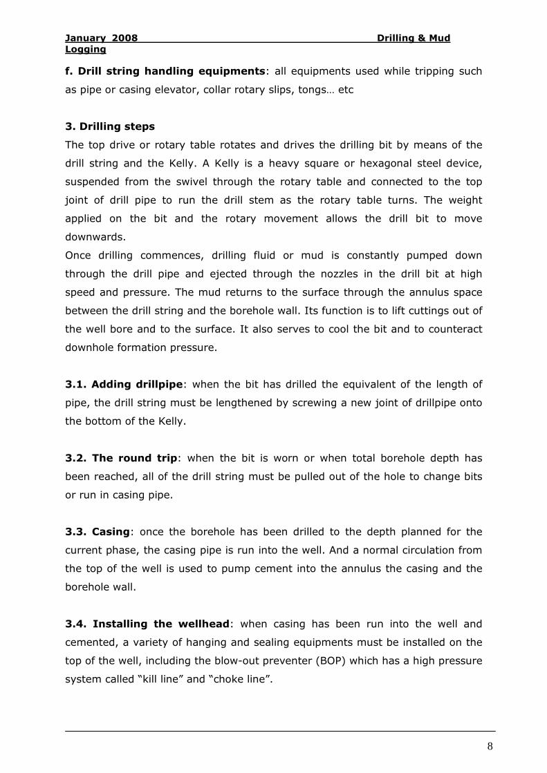
f. Drill string handling equipments: all equipments used while tripping such
as pipe or casing elevator, collar rotary slips, tongs… etc
3. Drilling steps
The top drive or rotary table rotates and drives the drilling bit by means of the
drill string and the Kelly. A Kelly is a heavy square or hexagonal steel device,
suspended from the swivel through the rotary table and connected to the top
joint of drill pipe to run the drill stem as the rotary table turns. The weight
applied on the bit and the rotary movement allows the drill bit to move
downwards.
Once drilling commences, drilling fluid or mud is constantly pumped down
through the drill pipe and ejected through the nozzles in the drill bit at high
speed and pressure. The mud returns to the surface through the annulus space
between the drill string and the borehole wall. Its function is to lift cuttings out of
the well bore and to the surface. It also serves to cool the bit and to counteract
downhole formation pressure.
3.1. Adding drillpipe: when the bit has drilled the equivalent of the length of
pipe, the drill string must be lengthened by screwing a new joint of drillpipe onto
the bottom of the Kelly.
3.2. The round trip: when the bit is worn or when total borehole depth has
been reached, all of the drill string must be pulled out of the hole to change bits
or run in casing pipe.
3.3. Casing: once the borehole has been drilled to the depth planned for the
current phase, the casing pipe is run into the well. And a normal circulation from
the top of the well is used to pump cement into the annulus the casing and the
borehole wall.
3.4. Installing the wellhead: when casing has been run into the well and
cemented, a variety of hanging and sealing equipments must be installed on the
top of the well, including the blow-out preventer (BOP) which has a high pressure
system called “kill line” and “choke line”.

January 2008 Drilling & Mud
Logging
9
A series of pressure tests on the casing (protect both subsurface formation and
the wellbore), hangers (cables such as drawworks which spools of or takes in the
drilling line and raises or lowers the drill stem and bit), and BOP (control
pressures during drilling) finalise the installation. After that the next drilling
phase can commence if safety requirements were met.
3.5. Completion: after running in the last casing string, the production
equipments must be installed in the well, including packer, tubing, safety valves,
etc. The connection between the producing formation and the well must often be
enhanced by drilling, perforations, acidizing, fracturing, etc.
January 2008 Drilling & Mud
Logging
10
III. MUDLOGGING
1. Introduction
Mud logging is one of the important activities in drilling operation; it serves as a
safety device as well as information gathering services.
Mud logging unit has mainly three parts, geological control, mud and drilling
parameters control (which is done by means of sensors) and gas detection
instruments.
The following chapter will be reserved to mud logging, a brief explanation of the
mud logging activities and the role of mud logging unit within the drilling site as
well as the role of some important parameters measured or calculated in drilling
operation.
2. Mud Logging Activities
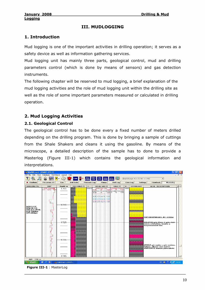
2.1. Geological Control
The geological control has to be done every a fixed number of meters drilled
depending on the drilling program. This is done by bringing a sample of cuttings
from the Shale Shakers and cleans it using the gasoline. By means of the
microscope, a detailed description of the sample has to done to provide a
Masterlog (Figure III-1) which contains the geological information and
interpretations.
Figure III-1 : MasterLog
January 2008 Drilling & Mud
Logging
11
1 2
3
4
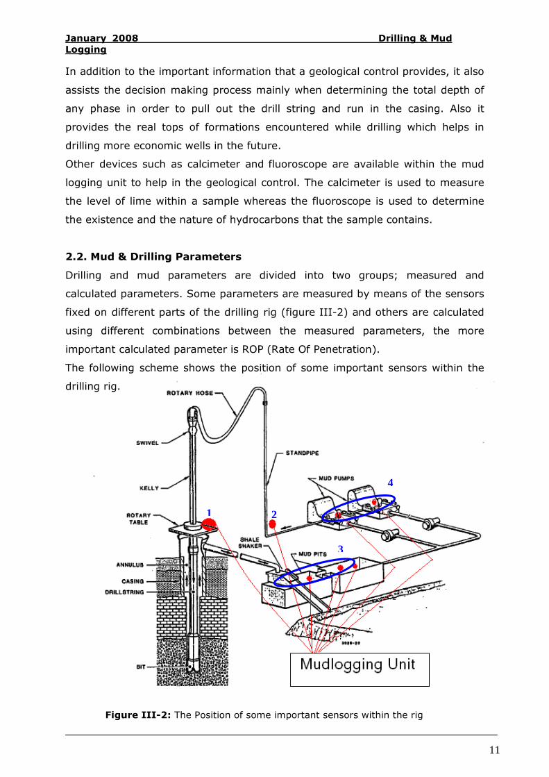
Figure III-2: The Position of some important sensors within the rig
In addition to the important information that a geological control provides, it also
assists the decision making process mainly when determining the total depth of
any phase in order to pull out the drill string and run in the casing. Also it
provides the real tops of formations encountered while drilling which helps in
drilling more economic wells in the future.
Other devices such as calcimeter and fluoroscope are available within the mud
logging unit to help in the geological control. The calcimeter is used to measure
the level of lime within a sample whereas the fluoroscope is used to determine
the existence and the nature of hydrocarbons that the sample contains.
2.2. Mud & Drilling Parameters
Drilling and mud parameters are divided into two groups; measured and
calculated parameters. Some parameters are measured by means of the sensors
fixed on different parts of the drilling rig (figure III-2) and others are calculated
using different combinations between the measured parameters, the more
important calculated parameter is ROP (Rate Of Penetration).
The following scheme shows the position of some important sensors within the
drilling rig.
January 2008 Drilling & Mud
Logging
12
Sensor
number
Sensor name
Description
1
Weight & depth
By Monitoring the hook position, depth can be
easily determined. The weight on bit is
calculated by assembling the equipments
above the bit and taking into account the
opposite force of the mud and the formation
being drilled.
All these are done by the sensor which is
attached to the cable hanging these
equipments.
2
Standpipe Pressure
This sensor measures the pressure at which
the mud is passed through the standpipe to the
well.
3
Pits Level
Determine the level of the mud within the pits.
It can be showed by every single pit or can be
assembled and showed as gain/loss in the total
active pits.
4 Stroke Per Minute When measuring the number of strokes, the
mud flow in can be determined.
In addition to the sensors mentioned above, we can find many others such as
density sensor, torque sensor, mud temperature sensor and so on. They are
installed depending on the demand of the client.
By means of these sensors, the mudlogging unit receives the signals to its
stations. After calibrating these signals they will appear as a numerical values
and charts and they will allow to the software to calculate and show many
parameters in a real time.
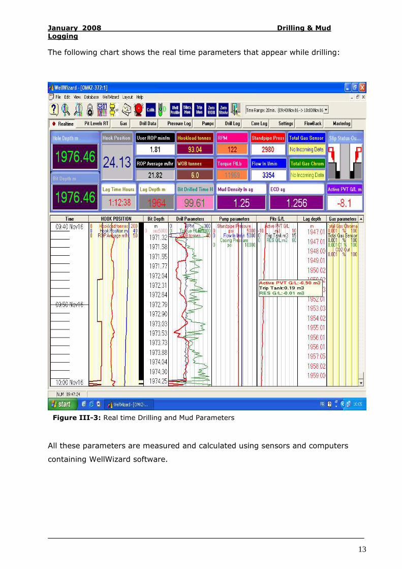
Among these parameters we can find the hole depth, bit depth, hook position,
lag time, ROP user and average, hookload, weight on bit, Bit drilled time …. Etc
(figure III-3)
January 2008 Drilling & Mud
Logging
13
The following chart shows the real time parameters that appear while drilling:
All these parameters are measured and calculated using sensors and computers
containing WellWizard software.
Figure III-3: Real time Drilling and Mud Parameters
January 2008 Drilling & Mud
Logging
14
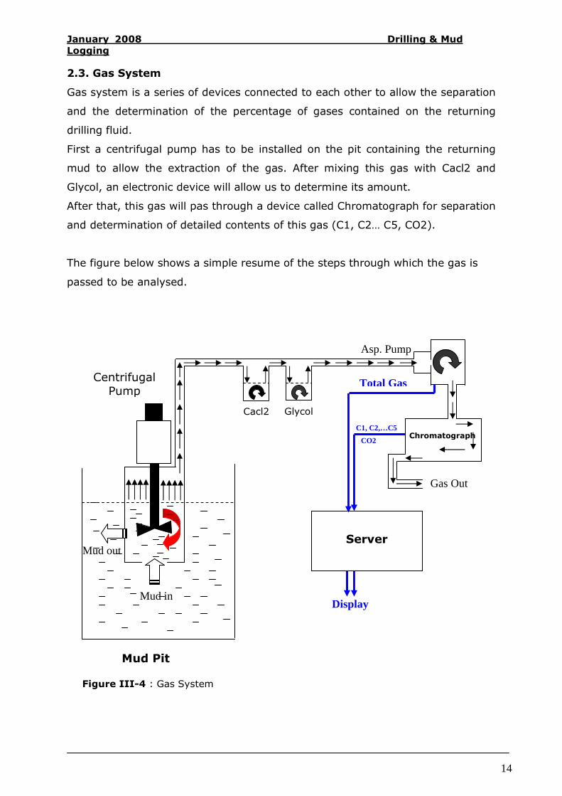
2.3. Gas System
Gas system is a series of devices connected to each other to allow the separation
and the determination of the percentage of gases contained on the returning
drilling fluid.
First a centrifugal pump has to be installed on the pit containing the returning
mud to allow the extraction of the gas. After mixing this gas with Cacl2 and
Glycol, an electronic device will allow us to determine its amount.
After that, this gas will pas through a device called Chromatograph for separation
and determination of detailed contents of this gas (C1, C2… C5, CO2).
The figure below shows a simple resume of the steps through which the gas is
passed to be analysed.
Display
Chromatograph
Total Gas
Asp. Pump
Mud out
Mud in
CO2
C1, C2,…C5
Server
Mud Pit
Centrifugal Pump
Cacl2 Glycol
Gas Out
Figure III-4 : Gas System
January 2008 Drilling & Mud
Logging
15
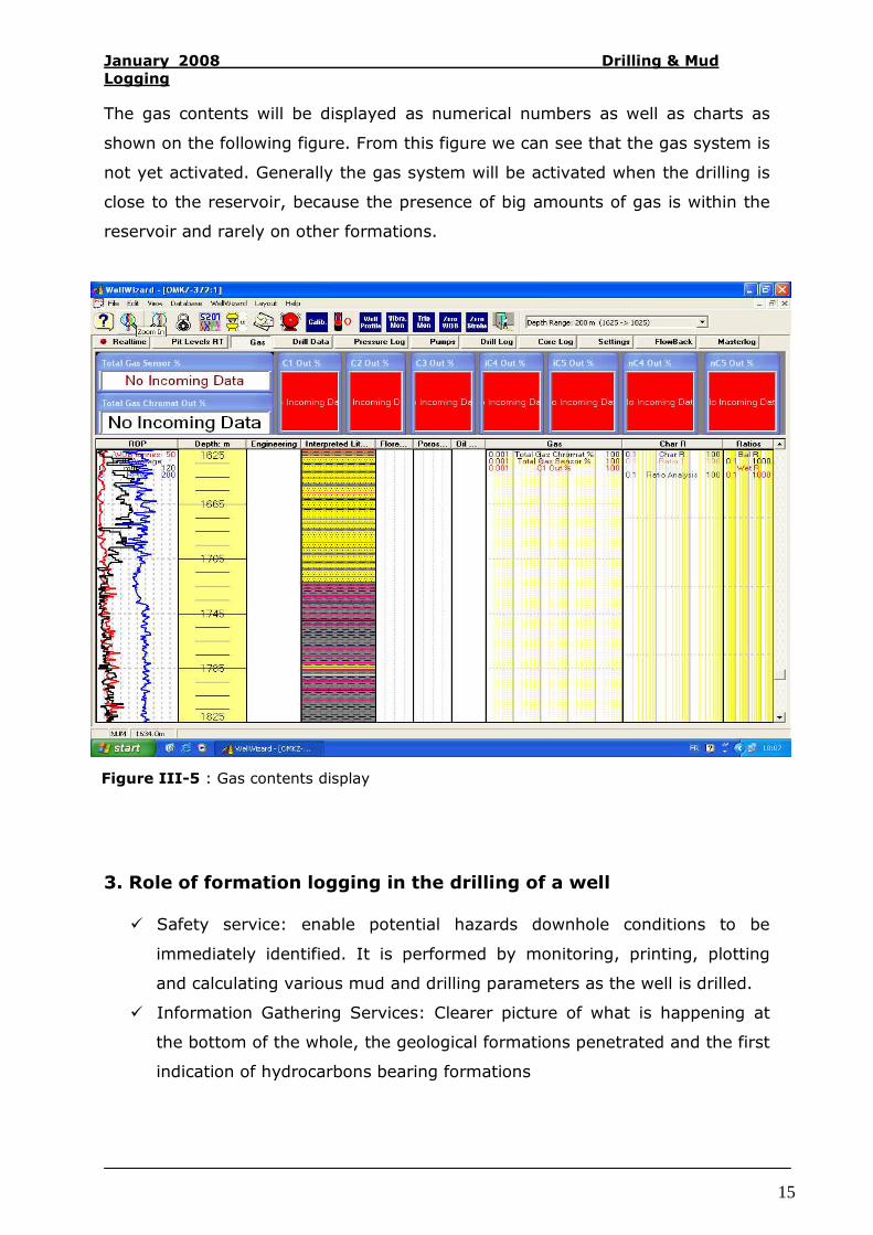
The gas contents will be displayed as numerical numbers as well as charts as
shown on the following figure. From this figure we can see that the gas system is
not yet activated. Generally the gas system will be activated when the drilling is
close to the reservoir, because the presence of big amounts of gas is within the
reservoir and rarely on other formations.
3. Role of formation logging in the drilling of a well
� Safety service: enable potential hazards downhole conditions to be
immediately identified. It is performed by monitoring, printing, plotting
and calculating various mud and drilling parameters as the well is drilled.
� Information Gathering Services: Clearer picture of what is happening at
the bottom of the whole, the geological formations penetrated and the first
indication of hydrocarbons bearing formations
Figure III-5 : Gas contents display
January 2008 Drilling & Mud
Logging
16
3.1. Role of Gas Detection Instruments
3.1.1. Total Gas: the percentage of the presence of gas in the mud. Mud
becoming increasingly gas (if left unchecked can lead to a blowout).
3.1.2. Chromatographic Analysis: (the presence of hydrocarbon gases such
as methane, ethane, propane … etc). Make the difference between gas and oil
reservoirs.
3.1.3. Hydrogen Sulphide: is monitored purely for safety purposes
3.1.4. Carbon Dioxide: Kicks and blowouts have been known to result from
CO2 Gas Reservoirs.
3.2. Role of Mud Monitoring Instruments 3.2.1. Mud Pit Levels: by continuously monitoring the mud level in the active
pit, one can see immediately any gain in level resulting from an influx of fluids
into the borehole – as well as the drop in level may indicate loss of circulation.
For a good functioning a good communication should be established between
mud logger, mud engineer and drilling personnel.
3.2.2. Mud Temperature: is monitored to assist in the detection of
overpressure formations.
3.2.3. Mud Weight:
- Can indicate the influx of formation fluids into the borehole
- Decrease in density of the mud as it reaches the surface may result from
the mud becoming Gas Cut.
- Small quantities of gas entering the mud at depth will have very little
effect on the density – the same amount of gas under reduced pressure
(near surface) may reduce the density of the mud significantly.
3.2.4. Pump Stroke Counter: Measures the rate at which mud is pumped down
the hole.
January 2008 Drilling & Mud
Logging
17
3.2.5. Mud Flow: is again a very useful tool in determining whether formation
fluids are entering the borehole (immediate increase in the mud returns flow
rate).
3.2.6. Mud Resistivity and Chloride Content
Formation fluids (usually saline) entering the borehole will increase the mud
conductivity (i.e. decrease the mud resistivity) and increase the chloride content
of the mud.
3.2.7. Alarm Systems:
Alarm systems both audible and visual are connected to some of the mud
monitoring instruments as well as total gas and H2S detectors. Particularly
significant are the alarms on the mud flow, mud pit and mud weight (out)
systems.
3.2.8. Trip Tanks:
During tripping it is vital that the level of mud in the trip tank is continuously
monitored. It is after all the most likely time when circulation will be lost or a
kick will occur (due to the swab surge effects of moving the drill string).
3.3. Role of Drilling Monitoring Instruments
3.3.1. Rate Of Penetration (ROP): It is a good tool for correlation purposes
and for detailed geological analysis. Additionally various calculated parameters
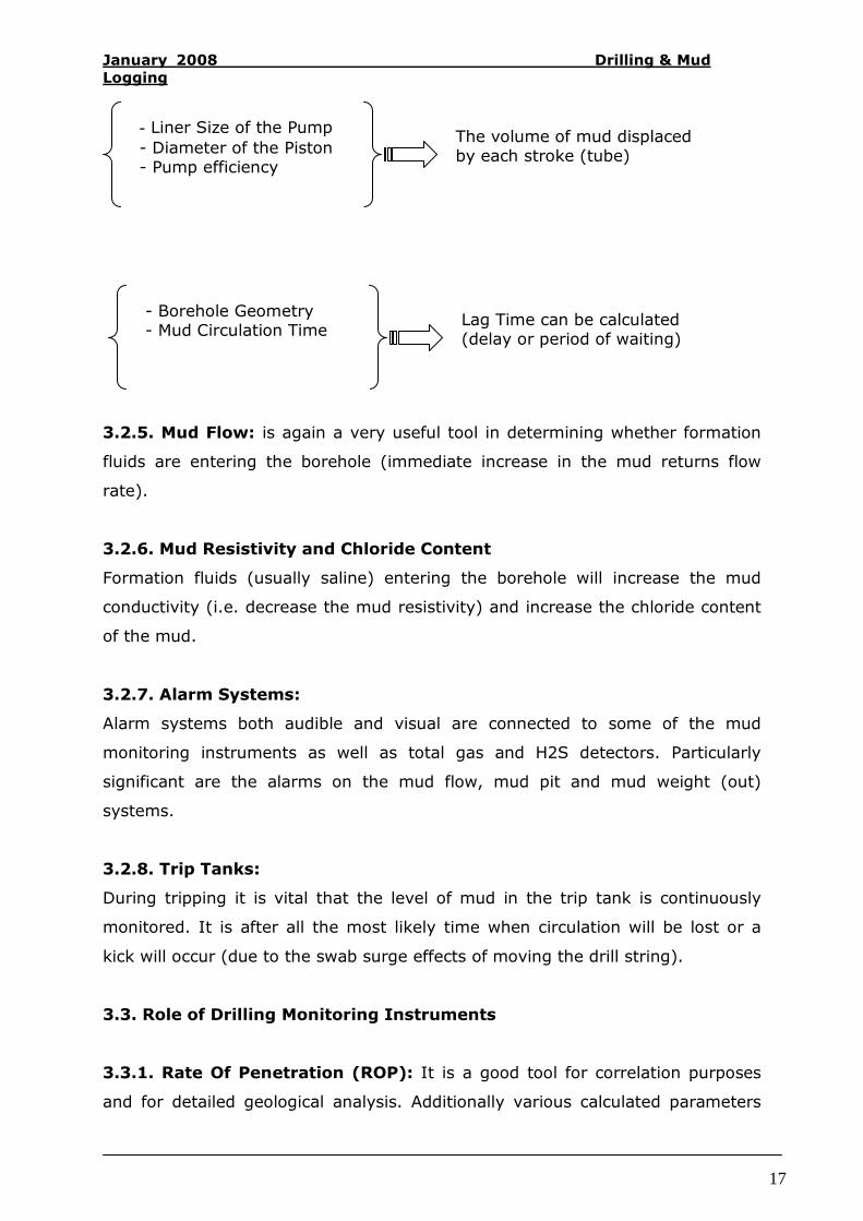
- Liner Size of the Pump
- Diameter of the Piston - Pump efficiency
The volume of mud displaced by each stroke (tube)
- Borehole Geometry - Mud Circulation Time
Lag Time can be calculated (delay or period of waiting)

January 2008 Drilling & Mud
Logging
18
bases on rate of penetration can be useful in identifying over pressured
formations.
The Rate Of Penetration is not solely dependent on type of lithology. It is also
affected by:
a). weight on bit
b). Rotary rpm
c). Degree of bit and bearing wear
d). effective bottom hole cleaning which itself is dependent upon the bottom hole
assembly.
e). Mud properties: especially mud weight, and the consequent differential
pressure between formation and mud column.
Slow ROP not associated with lithology change, may will indicate that the bit is
becoming worn although bit wear usually takes on major significance only
towards the very end of the bit life.
3.3.2. Rotary RPM: used to calculate normalized rate of penetration from
observed rate of penetration.
Changes in RPM do affect rate of drilling but under normal operating conditions,
changes in RPM are not as significant in effecting ROP as changes in weight of
bit.
3.3.3. Hook load / Weight on bit: is used for calculating normalized rate of
penetration. It is also a useful indicator to have present in the logging unit as
changes in the rate of penetration may not be due to changes in weight on bit. It
is also a useful way of identifying tight spots … etc
3.3.4. Standpipe or Pump Pressure: provides information concerning the
integrity of the drill string. Should a hole develop in the string the mud will pass
though it instead of going through the bit. This hole is termed a "washout" and if
left unchecked the erosional force of the fluid will enlarge it and eventually the
drill string will break (sometimes called a "twist off").
It is also used as a secondary indicator of a kick.
Reduction in standpipe pressure would be expected as soon as formation fluids
enter the borehole.

January 2008 Drilling & Mud
Logging
19
3.3.5. Rotary Torque: can indicate potential overpressure zones resulting from
sloughing in brittle formations and the production of sticky regions in the gummy
formations.
Increase in torque may will result from worn bits or bearings, lost cones, rotary
rpm increases, weight on bit increases, rate of penetration and lithological
changes, less efficient bottom hole cleaning, key seating and differential sticking.
It is a matter of experience in identifying the correct reason for torque
increasing.
IV. CONCLUSION
The realisation of this paper is a result of six weeks of training in tow different
drilling sites. This has been allowed us to consolidate the theoretical information
and be involved in real life, have a real picture of what is happening and
understand much more the drilling and mud logging activities.
This paper explores briefly the drilling operation and shows the importance of
mud logging unit within the drilling site. It demonstrates the importance of each
parameter provided by the mud logging unit and illustrates their benefits when
monitored effectively.

January 2008 Drilling & Mud
Logging
20
V. BIBLIOGRAPHY
Dtatlog Manual (Mud logging)
Halliburton Manual (Mud Logging)
International Association of Oil and Gas Producers (IAOGP), 2003
“Environmental Aspects of the Use and Disposal of Non Aqueous Drilling Fluids
Associated with Offshore Oil & Gas Operations” Report N°342.
Nguyen J. P, 1996: Drilling, Edition Technip. Paris,
U. S Department of Labor, 2001: Occupational Safety & Health
Administration, Glossary of terms,