Embed Size (px)
Citation preview

Drilling of Multi-Layer Composite Materials consisting of Carbon Fiber Reinforced Plastics (CFRP), Titanium and Aluminum Alloys
Property
Tensile strength
Modulus of elasticity
E. Brinksmeierl ( I ) , R. Janssen’ University of Bremen
Faculty of Production Technology, Division of Manufacturing Processes Bremen, Germany
1
Unit Value
Nlmm’ 108000
Nlmm’ 900
Abstract In this paper results are presented concerning the realization of economical drilling processes of multi-layer materials. Different carbide drill designs with improved geometries and coatings were investigated and compared by characterizing the cutting forces, tool wear, hole quality, and chip formation. Investigations have shown that dry machining of titanium workpiece layers leads to increased tool wear, chip formation problems, and surface damage in the aluminum and CFRP-layers. Consequently, the drilling experiments were carried out with minimum quantity lubrication (MQL) using different cutting fluids and supply strategies. The investigations were mainly focused on the development of the optimum drilling condition with respect to tool shape, tool material, and machining parameters. Another objective of the investigations was to analyze surface defects of the hole and the resulting diameter tolerances due to the high mechanical and thermal loads when machining titanium.
Keywords: Drilling, Titanium, Carbon Fiber Reinforced Plastics
1 INTRODUCTION Because of their high strength-to-weight ratios carbon fiber reinforced plastics (CFRP) are advantageous for use in structures for aerospace applications. In a wide range of applications dissimilar material stack-ups of composites and aluminum andlor titanium are used for wing or tail plane structures. Such structures contain holes for various purposes such as bolt holes. Diameter tolerances of 30 pm and lower are required for these applications. The machining characteristics of these materials, when sandwiched together, introduce a variety of drilling problems which require special set-ups or alternative processes [ I ] . Figure 1 gives an overview of the most relevant problems when machining these materials.
like the modulus of elasticity also affect the diameter tolerances of holes in sandwich materials. Regarding the problematic cutting conditions - especially at high diameterldepth ratios - improved tool geometries have been designed. Based on the characterization of demands caused by machining dissimilar materials, the tools were designed specifically to accommodate the drilling requirements of the different materials and material combinations with respect to industrial requirements.
2
2.1 Titanium Alloy TiA16V4 A characteristic feature of titanium alloys is their adhesion tendency which causes chip build-up at the cutting edges. Especially when using HSS-tools the tendency of chips to weld on the cutting edge is a significant wear form. In addition to the generation of build-up edges, adhesion of chips on the tool flank appears as well. One reason for this is the local deflection of the workpiece material during the cutting process caused by the low modulus of elasticity of titanium alloys (table 1).
SELECTION OF MATERIALS AND WORKPIECES
Density (20 “C) I g/cm3 14.43
Table 1 : Material properties of TiA16V4.
This leads to higher friction on the tool flank as well as to hiaher temDeratures in the contact zone. The breakaae of
Figure 1 : Problems when drilling multi-layer materials.
Apart from the intense tool wear caused by the high loads during the process erosion and abrasion in the CFRP- layer are critical for application as aerospace materials [2]. In addition, industrial needs and circumstances such as the avoidance of cooling lubrication also increase the efforts to obtain successful machining results and require a highly efficient machining technology. Besides the problematic chip transport, dissimilar material properties
tool particles is also connected with the weld of chips on the tool surface. During the cutting operation the chip is sheared off and takes along particles of the cutting edge. The use of wear resistant coatings like titanium nitride (TIN) intensifies this effect [3, 4, 5, 61. Especially when drilling TiA16V4 dry or with MQL, the unfavorable chip formation leads to chip removal problems and clogged flutes [7].

2.2 Aluminum Alloy AICuMg2 Aluminum wrought alloys such as AICuMg2 are known for good to excellent machinability. Drilling aluminum wrought alloys using conventional drills has essential advantages such as low specific cutting forces, low tool wear, and high surface quality. Yet, build-up edges and long ribbon chips may cause surface defects [8]. The material properties of the used AICuMg2 alloy are given in table 2.
Tool Specification
Type No. of flutes Diameter
Point angle Helix angle
Property Unit Value
Tensile strength
Modulus of elasticity
Density (20 "C)
Table 2: Material properties of AICuMg2.
A B
3 3
3 0" 30" 130" 130"
conventional drill step drill
16 mm 15.4/16 mm
2.3 Carbon Fiber Reinforced Plastics (CFRP) It is known from experimental investigations that the general cutting conditions applied to metals can be applied to composite materials as well. Therefore it is possible to drill CFRP using conventional twist drills, if wear resistance is suitable to resist the abrasion caused by the carbon fibers [2, 9, 101. For the machining experiments discussed in this paper panels of a carbon fiber reinforced epoxy resin were used. This carbon fiber/ epoxy resin contains continuous unidirectional fiber layers with orientations of O", 45", and 90". Properties and a microscopic view of the material are shown in figure 2.
Coatings
Property Unit Value Tensile strength Nlmm' Modulus of elasticity (yield)
Density (20 "C) Figure 2: Material properties of CFRP-workpieces.
uncm ted - uncoated - TiB,
- Diamond
3 EXPERIMENTAL SET-UP The presented studies on drilling of multi-layer materials consisting of aluminum, CFRP and titanium alloys have been undertaken to improve process stability and workpiece quality. As part of the experiments, effects of tool geometry and drilling parameters on cutting forces and hole quality were investigated. Drilling tests were conducted on a machining center in which the torque and the thrust force during machining were measured with power detection equipment and a Kistler piezoelectric force measurement device. The signals were transmitted to an analogldigital converter and managed via a data acquisition system. The experiments were carried out on sandwich materials of aluminum, CFRP, and titanium in dissimilar combinations with a thickness of 30 mm. Figure 3 shows
Workpiece
Cutting Speed vc
the workpiece specifications used in the tests. The individual material layers were connected with bolts. Between the layers a so-called shim-layer of 1 mm epoxy sealing material has been applied.
CFRP / Al
10, 20 mlmin
Al / CFRP / Ti
10, 20 rnfmin
10mm I I AICuMg2
10mm I I AICuMg2
Figure 3: Workpiece specifications
The specimens were drilled in a two-step process using carbide drills with diameters of 6 mm and 16 mm. The main focus of the investigation lay on the design of the 16- mm-diameter drills used after pre-drilling with 6-mm- diameter drills. A conventional drill (A) and an optimized step drill (B) designed with a diameter step of 15.4 mm (pre-drilling) to 16.0 mm (secondary step for finishing) with different coatings have been selected for the experiments. Tool geometry B has been designed in order to reduce the thermal and mechanical loads on the cutting edges and to improve the hole accuracy along the entire hole depth. Table 3 gives an overview of the used tool specifications.
I I
Example of Diameter step 15.4 mm to
uncoated 16.0 mm
Table 3: Drill specifications.
The investigations were performed with machining parameters selected close to industrial experiences (table 4).
I Feed f I 0.15 mm I 0.15 mm I I Cooling I dry/ oil mist I oil mist I Tool Reverse Motion every 10 mm every 10 mm for Chip Removal
Table 4: Drilling parameters.
To drill the material specification AIICFRPTTiAI6V4 an oil mist lubrication with fetty alcohol through the spindle has been used.
4 RESULTS OF INVESTIGATION
4.1 Workpiece quality when drilling CFRPlalurninurn Due to the different material properties, holes with small diameter tolerances are difficult to drill. The modulus of elasticity E of the materials causes different elastic deformations and therefore varying tolerances along the entire hole. Additionally, the chip transport through the hole as well as build-up cutting edges of aluminum at the primary and minor cutting edges combined with increased tool wear affect the hole quality. Figure 4 shows the resulting drill hole diameters and the tolerances of the diameter values for different tool specifications. When using a conventional boring tool (geometry A), deviations of the diameters are in a range of nearly 80 pm. Due to the low modulus of elasticity of CFRP, the diameter values in the CFRP-layer are distinctly lower compared with the diameters in the aluminum layer. The use of an optimized tool geometry (geometry B) evidently improves the tolerances. Apart from the diamond-coated tool specification, the tolerances of the hole diameters were significantly reduced when using the step drill. The reduction of mechanical loads by distribution on several cutting edges causes minor elastic behavior and therefore lower tolerances. In the case of the diamond-coated tool the edge-holding property and the sharpness are not suitable for the machining of CFRP- material. Additional improvement can be reached by using minimum quantity lubrication (MQL) instead of dry machining. Studies made using MQL with fetty alcohol through internal coolant channels in the drills show that diameter tolerances of 17 pm along the entire hole can be reached. Furthermore, the use of MQL has revealed clear benefits in terms of chip removal due to the improved friction conditions. The adhesion of aluminum particles on the chip grooves is clearly reduced by MQL.
Figure 4: Hole diameter when drilling CFRPlaluminum with different tool specifications
(Machining conditions refer to table 4).
4.2 Tool wear when drilling CFRPlalurninurn As mentioned before, the use of step drills and the use of minimum quantity lubrication improve the process characteristics when drilling multi-layer materials. Apart from the diameter tolerances, the tool wear can also be affected significantly. For clarification SEM inspection of the minor cutting edges of the secondary step flutes is shown in figure 5. It shows a comparison between dry machining and MQL at a tool life index of 15 holes. When using MQL through the coolant channels of the tool the adhesion of aluminum build-up edges at the cutting edge and the flank can be clearly reduced. The build-up edges at the flank are responsible for increased machining tolerances and insufficient surface qualities.
Figure 5: Comparison of tool wear when drilling CFRPl aluminum with or without MQL.
4.3 Workpiece quality when drilling aluminum/ CFRPlt itan iurn
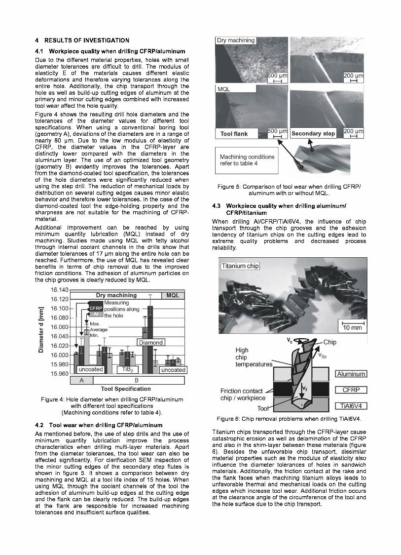
When drilling AIlCFRPlTiAI6V4, the influence of chip transport through the chip grooves and the adhesion tendency of titanium chips on the cutting edges lead to extreme quality problems and decreased process reliability.
Figure 6: Chip removal problems when drilling TiA16V4.
Titanium chips transported through the CFRP-layer cause catastrophic erosion as well as delamination of the CFRP and also in the shim-layer between these materials (figure 6). Besides the unfavorable chip transport, dissimilar material properties such as the modulus of elasticity also influence the diameter tolerances of holes in sandwich materials. Additionally, the friction contact at the rake and the flank faces when machining titanium alloys leads to unfavorable thermal and mechanical loads on the cutting edges which increase tool wear. Additional friction occurs at the clearance angle of the circumference of the tool and the hole surface due to the chip transport.

The transport of chips through the chip groove is mainly problematic regarding the CFRP-layer and the connecting shim-layer between the CFRP- and the titanium layer. Erosion at the CFRP caused by hot and sharp-edged titanium chips leads to insufficient surface qualities and functional problems in subsequent assembly processes. An example of the depth of erosion along the CFRP-layer is shown in figure 7. The depth of erosion in this case has a value of approximately 300 pm. When using the tool specification B the erosion problems can be clearly reduced. The secondary step of the tool acts like a reaming tool and leads to improved chip transport.
Figure 7: Roughness profile of a hole machined with tool specification A
(Machining conditions refer to table 4).
4.4 Tool wear when drilling alurninurnlCFRPl TiA16V4 Investigations have shown that the friction contact at the rake and the flank faces when drilling titanium alloys leads to unfavorable thermal and mechanical loads on the cutting edges which increase tool wear. Therefore, the tool life index when machining aluminum/ CFRPltitanium is limited to a small number of holes.
Figure 8: Tool wear when drilling aluminum/ CFRPltitanium with different cutting speeds
(Machining conditions refer to table 4)
Experiments with different tool specifications and tool coatings have shown that improvements concerning the wear behavior of tools are mainly dependent on tool geometry and cutting parameters. The influence of wear resistant coatings is only minor. The influence of the cutting speed on the tool wear when drilling aluminum/CFRP/titanium is shown in figure 8. It is apparent that a reduction of cutting speed vc from 20 to 10 m/min significantly reduces the adhesion of titanium chips on the cutting edges.
5 CONCLUSION Extensive drilling experiments on multi-layer materials using conventional and optimized twist drills were carried out to investigate the influence of tool geometry, cutting parameters, and cutting fluids. With regard to the workpiece quality, diameter tolerances, and tool wear the following conclusions can be drawn: 0 The use of adapted step drills improves diameter
tolerances, surface quality, and tool wear. 0 Improvements when using tool coatings of TiB2 or
diamond are only achievable with regard to tool wear. 0 When drilling multi-layer materials, MQL with internal
supply should be used.
0 Pre-drilling and chip removing circles should be applied.
6 REFERENCES Tonshoff, H. K., Friemuth, T., Groppe, M. 2001, High Efficient Circular Milling - A Solution for an Economical Machining of Bore Holes in Composite Materials (CFK, aluminum), 2001, Proceedings of 3rd International Conference on Metal Cutting and High Speed Machining, June 27, 28, 2001, Metz (France).
Park, K. Y., Choi, J. H., Lee, D. G., 1995, Delamination-Free and High Efficiency Drilling of Carbon Fiber Reinforced Plastics. J. of Composite Materials, Vol. 29/No. 15/1995, pp. 1988 - 2002.
Brinksmeier, E., Berger, U., Janssen, R., 1997, High Speed Machining of TiA16V4 for Aircraft Applications, Proceedings of 1" French and German Conference on High Speed Machining, 17. - 18.06. 1997, Metz (France).
Brinksmeier, E., Berger, U., Janssen, R., 1998, Advanced Sensoric and Machining System for Manufacturing and Repair of Jet Engine Components, Proceedings of 31" CIRP International Seminar on Manufacturing Systems, 26.05. - 28.05.1998, Berkeley (USA).
Klocke, F., Krieg, T., 1999, Coated Tool for Metal Cutting - Features and Applications, Keynote Paper, Annals of the CIRP, 48/2/1999.
Hartung, P. D., Kramer, B. M., 1982, Tool Wear in Titanium Machining, Annals of the CIRP, 31/1/1982
Schulz, H., Emrich, A. K., 1998, Limitations of Drilling in Difficult-to-Machine Materials such as Titanium TiA16V4, 1998, Production Engineering, Vol. V/1, pp.
Eisenblatter, G., 2000, Trockenbohren mit Voll- hartmetallwerkzeugen, PhD-Thesis, RWTH Aachen, (Germany).
Rahman, M., Ramakrishna, S., Prakash, J.R.S., Machinability study of carbon fiber reinforced composite. J. of Materials Processing Technology, Vol. 89-90/1999, S. 292 bis 297. Konig, W.; Wulf, C.; Grass, P.; Willerschied, H., 1985, Machining of Fiber Reinforced Plastics, Annals of the CIRP, 34/2/1985.
35-38.