Embed Size (px)
Citation preview
Drinking Water MachineAQUAPHOR DWM-101
System Tested and certified by NSF International against NSF/ANSI Standard 58 for the reduction of claims specified on performance data sheet.
INSTALLATION GUIDEVERSION 1.2
2 10/9/2013 Drinking Water MachineInstallation Guide
Drinking Water Machine 10/9/2013 3Installation Guide
To place the equipment under warranty, the warranty registration card must be completed and returned by the original owner to the warrantor, AQUAPHOR®, within 30 days of installation. P.O. Box 298, Groveport, OH 43125.
CoverageThis warranty covers specified parts of the
AQUAPHOR® Drinking Water Machine delivered to the original owner when the appliance is purchased from an AQUAPHOR® water treatment specialist.
Warrantor’s Performance and Length of Warranty
AQUAPHOR® warrants that upon receipt from the owner of any AQUAPHOR® assembly, valve assembly, storage tank, and dispensing spigot, found to be defective in material or workmanship, AQUAPHOR® will repair or replace the defective item, at no charge for that item, for 2 years from date of installation. Note: Replacement cartridges are not warranted.
Should a defect or malfunction occur, contact your water treatment specialist. If you are unable to contact your water treatment specialist, then contact AQUAPHOR® at 614-836-9422.
All defective parts must be returned, along with the equipment serial number and date of original installation, to an authorized AQUAPHOR® water treatment specialist or shipped to AQUAPHOR®
PREPAID, and replacement parts will be returned by AQUAPHOR® FREIGHT COLLECT. Please contact AQUAPHOR® at 614-836-9422, prior to shipping.
Further Exclusions and Limitations on Warranty:
This warranty is null and void unless the appliance was purchased from an AQUAPHOR® water treatment specialist.
THERE ARE NO WARRANTIES OTHER THAN THOSE DESCRIBED IN THIS WARRANTY INSTRUMENT.
This warranty does not cover any service call or labor costs incurred with respect to the removal and replacement of any defective part or parts. AQUAPHOR® will not be liable for, nor will it pay service call or labor charges incurred or expended with respect to this warranty.
In the event the water supply being processed through this product contains bacterial iron, algae, sulphur, tannins, organic matter, or other unusual substances, then unless the appliance is represented as being capable of handling these substances in the appliance specifications, other special treatment of the water supply must be used to remove these substances before they enter this product. Otherwise, AQUAPHOR® shall have no obligations under this warranty.
This warranty does not cover damage to a part or parts of the appliance from causes such as fire, accidents, freezing, or unreasonable use, abuse, or neglect by the owner.
This warranty does not cover damage to a part or parts of the appliance resulting from improper installation. All plumbing connections should be made in accordance with all local codes and the installation instructions provided with the appliance. The warranty does not cover damage resulting from use with inadequate or defective plumbing; inadequate or defective water supply or pressure; or violation of applicable building and plumbing codes, laws, ordinances, or regulations.
THIS WARRANTY DOES NOT COVER INCIDENTAL, CONSEQUENTIAL, OR SECONDARY DAMAGES. ANY IMPLIED WARRANTIES ON THE PRODUCT DESCRIBED IN THIS WARRANTY WILL NOT BE EFFECTIVE AFTER THE EXPIRATION OF THIS WARRANTY.
No water treatment specialist, agent, representative, or other person is authorized to extend or expand this limited warranty.
Some states do not allow limitations on how long an implied warranty lasts or the exclusion or limitation of incidental or consequential damages, so the above limitations and exclusion may not apply to you. This warranty gives you specific legal rights, and you may also have other rights which vary from state to state.
OWNER INFORMATION 4Safety Instructions 4Service Log 4Introduction to Drinking Water Machine 5Drinking Water Machine Appliance 6Drinking Water Machine Filter Labels 7Recommended Filter Replacement 7Recommended Filter Maintenance 8
INSTALLATION AND MAINTENANCE INFORMATION 9Checklist Before Installation 9Installation Tool List 10Typical Flow Diagram 10Installation Steps and Start-Up Procedures 12Changing Filters 17Maintenance Procedures 18Assembly and Parts 21Troubleshooting 24Specifications 25
2 Year Limited Warranty Contents
4 10/9/2013 Drinking Water MachineInstallation Guide
Drinking Water Machine 10/9/2013 5Installation Guide
Warning: This appliance must be applied to potable water only. It is recommended that a water treatment specialist install and maintain this appliance.
Note: The manufacturer reserves the right to make specification and product changes without prior notice.
When installing the appliance into a local water supply, it is recommended to conduct a water analysis. If the water analysis does not correspond with the requirements, the lifetime of the filtration cartridges and membrane unit may be significantly reduced. In this case, it is recommended to use auxiliary water treatment systems (e.g. mechanical filter, de-ironing filter, and/or water softener). It is recommended to use only microbiological safe water with your Drinking Water Machine appliance.
Caution: Do not use water that is microbiologically unsafe or of unknown quality without adequate disinfection before or after the appliance.
Safety InstructionsOwner Information
Service Log
We recommend that you have your local water treatment specialist service this appliance. Ensure that all items are checked when servicing the appliance. The Service Log label is located under the decorative cover.
Date
Repla
ceme
nt filt
er ca
rtridg
e K5 (
1)
Repla
ceme
nt filt
er ca
rtridg
e K2 (
2)
Memb
rane
Car
tridge
(Hou
sing w
ith
prein
stalle
d mem
bran
e elem
ent)
(3)
Repla
ceme
nt filt
er ca
rtridg
e K7M
(4)
Flow
Restr
ictor
Chec
k valv
e
Appli
ance
Shu
toff V
alve
Wate
r pre
ssur
e
Wate
r tem
pera
ture
pH Incom
ing T
DS
Trea
ted T
DS
% R
ejecti
on
% R
ecov
ery
Notes
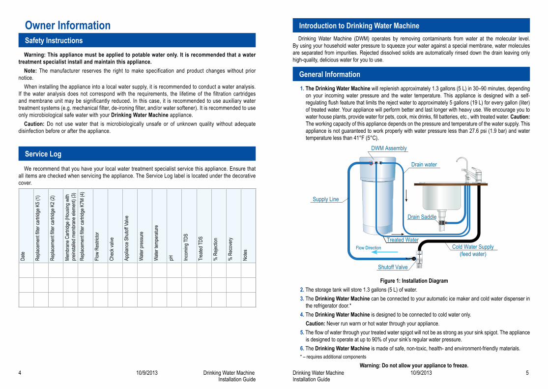
1. The Drinking Water Machine will replenish approximately 1.3 gallons (5 L) in 30–90 minutes, depending on your incoming water pressure and the water temperature. This appliance is designed with a self-regulating flush feature that limits the reject water to approximately 5 gallons (19 L) for every gallon (liter) of treated water. Your appliance will perform better and last longer with heavy use. We encourage you to water house plants, provide water for pets, cook, mix drinks, fill batteries, etc., with treated water. Caution: The working capacity of this appliance depends on the pressure and temperature of the water supply. This appliance is not guaranteed to work properly with water pressure less than 27.6 psi (1.9 bar) and water temperature less than 41°F (5°C).
Figure 1: Installation Diagram2. The storage tank will store 1.3 gallons (5 L) of water.3. The Drinking Water Machine can be connected to your automatic ice maker and cold water dispenser in
the refrigerator door.*4. The Drinking Water Machine is designed to be connected to cold water only.
Caution: Never run warm or hot water through your appliance.5. The flow of water through your treated water spigot will not be as strong as your sink spigot. The appliance
is designed to operate at up to 90% of your sink’s regular water pressure.6. The Drinking Water Machine is made of safe, non-toxic, health- and environment-friendly materials.* – requires additional components
Warning: Do not allow your appliance to freeze.
General Information
DWM Assembly
Drain water
Drain Saddle
Treated WaterCold Water Supply
(feed water)
Shutoff Valve
Flow Direction
Supply Line
Drinking Water Machine (DWM) operates by removing contaminants from water at the molecular level. By using your household water pressure to squeeze your water against a special membrane, water molecules are separated from impurities. Rejected dissolved solids are automatically rinsed down the drain leaving only high-quality, delicious water for you to use.
Introduction to Drinking Water Machine
6 10/9/2013 Drinking Water MachineInstallation Guide
Drinking Water Machine 10/9/2013 7Installation Guide
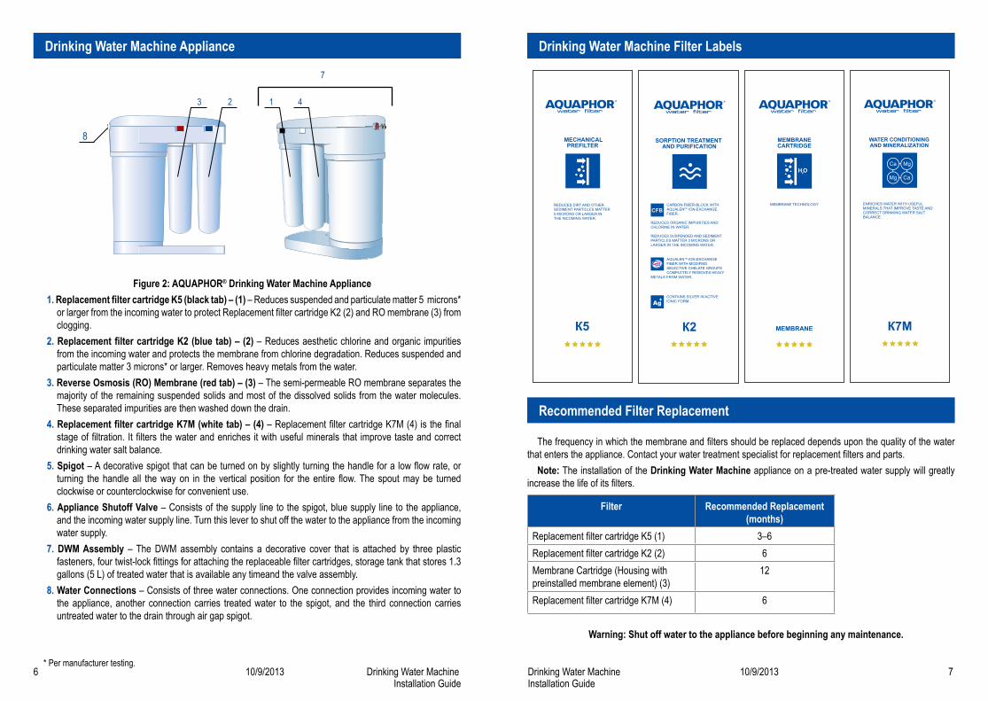
Figure 2: AQUAPHOR® Drinking Water Machine Appliance1. Replacement filter cartridge K5 (black tab) – (1) – Reduces suspended and particulate matter 5 microns*
or larger from the incoming water to protect Replacement filter cartridge K2 (2) and RO membrane (3) from clogging.
2. Replacement filter cartridge K2 (blue tab) – (2) – Reduces aesthetic chlorine and organic impurities from the incoming water and protects the membrane from chlorine degradation. Reduces suspended and particulate matter 3 microns* or larger. Removes heavy metals from the water.
3. Reverse Osmosis (RO) Membrane (red tab) – (3) – The semi-permeable RO membrane separates the majority of the remaining suspended solids and most of the dissolved solids from the water molecules. These separated impurities are then washed down the drain.
4. Replacement filter cartridge K7M (white tab) – (4) – Replacement filter cartridge K7M (4) is the final stage of filtration. It filters the water and enriches it with useful minerals that improve taste and correct drinking water salt balance.
5. Spigot – A decorative spigot that can be turned on by slightly turning the handle for a low flow rate, or turning the handle all the way on in the vertical position for the entire flow. The spout may be turned clockwise or counterclockwise for convenient use.
6. Appliance Shutoff Valve – Consists of the supply line to the spigot, blue supply line to the appliance, and the incoming water supply line. Turn this lever to shut off the water to the appliance from the incoming water supply.
7. DWM Assembly – The DWM assembly contains a decorative cover that is attached by three plastic fasteners, four twist-lock fittings for attaching the replaceable filter cartridges, storage tank that stores 1.3 gallons (5 L) of treated water that is available any timeand the valve assembly.
8. Water Connections – Consists of three water connections. One connection provides incoming water to the appliance, another connection carries treated water to the spigot, and the third connection carries untreated water to the drain through air gap spigot.
* Per manufacturer testing.
Drinking Water Machine Appliance
8
1 43 2
7
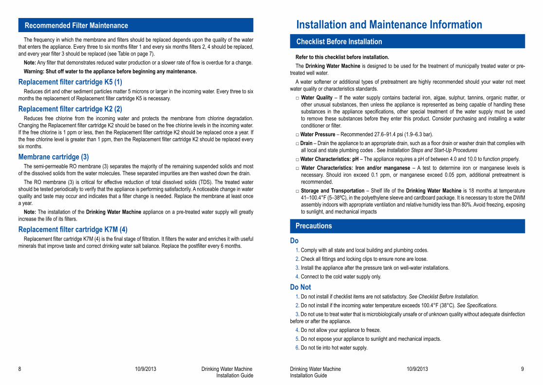
The frequency in which the membrane and filters should be replaced depends upon the quality of the water that enters the appliance. Contact your water treatment specialist for replacement filters and parts.
Note: The installation of the Drinking Water Machine appliance on a pre-treated water supply will greatly increase the life of its filters.
Filter Recommended Replacement (months)
Replacement filter cartridge K5 (1) 3–6Replacement filter cartridge K2 (2) 6Membrane Cartridge (Housing with preinstalled membrane element) (3)
12
Replacement filter cartridge K7M (4) 6
Warning: Shut off water to the appliance before beginning any maintenance.
Drinking Water Machine Filter Labels
Recommended Filter Replacement
8 10/9/2013 Drinking Water MachineInstallation Guide
Drinking Water Machine 10/9/2013 9Installation Guide
The frequency in which the membrane and filters should be replaced depends upon the quality of the water that enters the appliance. Every three to six months filter 1 and every six months filters 2, 4 should be replaced, and every year filter 3 should be replaced (see Table on page 7).
Note: Any filter that demonstrates reduced water production or a slower rate of flow is overdue for a change.Warning: Shut off water to the appliance before beginning any maintenance.
Replacement filter cartridge K5 (1)Reduces dirt and other sediment particles matter 5 microns or larger in the incoming water. Every three to six
months the replacement of Replacement filter cartridge K5 is necessary.
Replacement filter cartridge K2 (2)Reduces free chlorine from the incoming water and protects the membrane from chlorine degradation.
Changing the Replacement filter cartridge K2 should be based on the free chlorine levels in the incoming water. If the free chlorine is 1 ppm or less, then the Replacement filter cartridge K2 should be replaced once a year. If the free chlorine level is greater than 1 ppm, then the Replacement filter cartridge K2 should be replaced every six months.
Membrane cartridge (3)The semi-permeable RO membrane (3) separates the majority of the remaining suspended solids and most
of the dissolved solids from the water molecules. These separated impurities are then washed down the drain.The RO membrane (3) is critical for effective reduction of total dissolved solids (TDS). The treated water
should be tested periodically to verify that the appliance is performing satisfactorily. A noticeable change in water quality and taste may occur and indicates that a filter change is needed. Replace the membrane at least once a year.
Note: The installation of the Drinking Water Machine appliance on a pre-treated water supply will greatly increase the life of its filters.
Replacement filter cartridge K7M (4)Replacement filter cartridge K7M (4) is the final stage of filtration. It filters the water and enriches it with useful
minerals that improve taste and correct drinking water salt balance. Replace the postfilter every 6 months.
Refer to this checklist before installation.The Drinking Water Machine is designed to be used for the treatment of municipally treated water or pre-
treated well water.A water softener or additional types of pretreatment are highly recommended should your water not meet
water quality or characteristics standards.□ Water Quality – If the water supply contains bacterial iron, algae, sulphur, tannins, organic matter, or
other unusual substances, then unless the appliance is represented as being capable of handling these substances in the appliance specifications, other special treatment of the water supply must be used to remove these substances before they enter this product. Consider purchasing and installing a water conditioner or filter.
□ Water Pressure – Recommended 27.6–91.4 psi (1.9–6.3 bar).□ Drain – Drain the appliance to an appropriate drain, such as a floor drain or washer drain that complies with
all local and state plumbing codes . See Installation Steps and Start-Up Procedures□ Water Characteristics: pH – The appliance requires a pH of between 4.0 and 10.0 to function properly.□ Water Characteristics: Iron and/or manganese – A test to determine iron or manganese levels is
necessary. Should iron exceed 0.1 ppm, or manganese exceed 0.05 ppm, additional pretreatment is recommended.
□ Storage and Transportation – Shelf life of the Drinking Water Machine is 18 months at temperature 41–100.4°F (5–38ºC), in the polyethylene sleeve and cardboard package. It is necessary to store the DWM assembly indoors with appropriate ventilation and relative humidity less than 80%. Avoid freezing, exposing to sunlight, and mechanical impacts
Precautions
Do1. Comply with all state and local building and plumbing codes.2. Check all fittings and locking clips to ensure none are loose.3. Install the appliance after the pressure tank on well-water installations.4. Connect to the cold water supply only.
Do Not1. Do not install if checklist items are not satisfactory. See Checklist Before Installation.2. Do not install if the incoming water temperature exceeds 100.4°F (38°C). See Specifications.3. Do not use to treat water that is microbiologically unsafe or of unknown quality without adequate disinfection
before or after the appliance.4. Do not allow your appliance to freeze.5. Do not expose your appliance to sunlight and mechanical impacts.6. Do not tie into hot water supply.
Recommended Filter Maintenance
Checklist Before Installation
Installation and Maintenance Information
10 10/9/2013 Drinking Water MachineInstallation Guide
Drinking Water Machine 10/9/2013 11Installation Guide
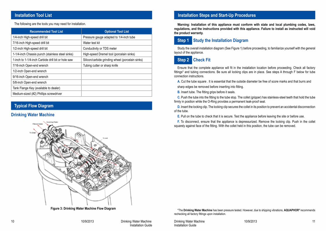
The following are the tools you may need for installation.
Recommended Tool List Optional Tool List1/4-inch High-speed drill bit Pressure gauge adapted to 1/4-inch tube7/16-inch High-speed drill bit Water test kit1/2-inch High-speed drill bit Conductivity or TDS meter1-1/4-inch Chassis punch (stainless steel sinks) High-speed Dremel tool (porcelain sinks)1-inch to 1-1/4-inch Carbide drill bit or hole saw Silicon/carbide grinding wheel (porcelain sinks)7/16-inch Open-end wrench Tubing cutter or sharp knife1/2-inch Open-end wrench9/16-inch Open-end wrench5/8-inch Open-end wrenchTank Flange Key (available to dealer)Medium-sized (#2) Phillips screwdriver
Typical Flow Diagram
Drinking Water Machine
Figure 3: Drinking Water Machine Flow Diagram
Installation Tool List
Warning: Installation of this appliance must conform with state and local plumbing codes, laws, regulations, and the instructions provided with this appliance. Failure to install as instructed will void the product warranty.
Step 1 Study the Installation DiagramStudy the overall installation diagram (See Figure 1) before proceeding, to familiarize yourself with the general
layout of the appliance.
Step 2 Check FitEnsure that the complete appliance will fit in the installation location before proceeding. Check all factory
fittings* and tubing connections. Be sure all locking clips are in place. See steps A through F below for tube connection instructions.
A. Cut the tube square . It is essential that the outside diameter be free of score marks and that burrs andsharp edges be removed before inserting into fitting.B. Insert tube. The fitting grips before it seals.C. Push the tube into the fitting to the tube stop. The collet (gripper) has stainless-steel teeth that hold the tube
firmly in position while the O-Ring provides a permanent leak-proof seal.D. Insert the locking clip. The locking clip secures the collet in its position to prevent an accidental disconnection
of the tube.E. Pull on the tube to check that it is secure. Test the appliance before leaving the site or before use.F. To disconnect, ensure that the appliance is depressurized. Remove the locking clip. Push in the collet
squarely against face of the fitting. With the collet held in this position, the tube can be removed.
*The Drinking Water Machine has been pressure tested. However, due to shipping vibrations, AQUAPHOR® recommends rechecking all factory fittings upon installation.
Installation Steps and Start-Up Procedures
12 10/9/2013 Drinking Water MachineInstallation Guide
Drinking Water Machine 10/9/2013 13Installation Guide
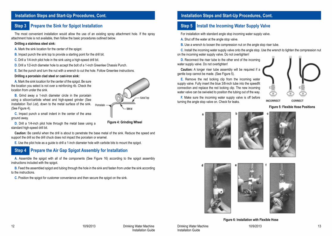
Step 3 Prepare the Sink for Spigot InstallationThe most convenient installation would allow the use of an existing spray attachment hole. If the spray
attachment hole is not available, then follow the basic procedures outlined below.Drilling a stainless steel sink:A. Mark the sink location for the center of the spigot.B. Impact punch the sink top to provide a starting point for the drill bit.C. Drill a 1/4-inch pilot hole in the sink using a high-speed drill bit.D. Drill a 1/2-inch diameter hole to accept the bolt of a 1-inch Greenlee Chassis Punch.E. Set the punch and turn the nut with a wrench to cut the hole. Follow Greenlee instructions.Drilling a porcelain clad steel or cast-iron sink:A. Mark the sink location for the center of the spigot. Be sure
the location you select is not over a reinforcing rib. Check the location from under the sink.
B. Grind away a 1-inch diameter circle in the porcelain using a silicon/carbide wheel and high-speed grinder (See Installation Tool List), down to the metal surface of the sink. (See Figure 4).
C. Impact punch a small indent in the center of the area ground away.
D. Drill a 1/4-inch pilot hole through the metal base using a standard high-speed drill bit.
Caution: Be careful when the drill is about to penetrate the base metal of the sink. Reduce the speed and support the drill so the drill chuck does not impact the porcelain or enamel.
E. Use the pilot hole as a guide to drill a 1-inch diameter hole with carbide bits to mount the spigot.
Step 4 Prepare the Air Gap Spigot Assembly for InstallationA. Assemble the spigot with all of the components (See Figure 16) according to the spigot assembly
instructions included with the spigot.B. Feed the assembled spigot and tubing through the hole in the sink and fasten from under the sink according
to the instructions.C. Position the spigot for customer convenience and then secure the spigot on the sink.
Step 5 Install the Incoming Water Supply ValveFor installation with standard angle stop incoming water supply valve.A. Shut off the water at the angle stop valve.B. Use a wrench to loosen the compression nut on the angle stop riser tube.C. Install the incoming water supply valve onto the angle stop. Use the wrench to tighten the compression nut
on the incoming water supply valve. Do not overtighten!D. Reconnect the riser tube to the other end of the incoming
water supply valve. Do not overtighten!Caution: A longer riser tube assembly will be required if a
gentle loop cannot be made. (See Figure 5).E. Remove the red locking clip from the incoming water
supply valve. Fully insert the blue 3/8-inch tube into the speedfit connection and replace the red locking clip. The new incoming water valve can be swiveled to position the tubing out of the way.
F. Make sure the incoming water supply valve is off before turning the angle stop valve on. Check for leaks.
Figure 6: Installation with Flexible Hose
Installation Steps and Start-Up Procedures, Cont. Installation Steps and Start-Up Procedures, Cont.
Figure 4: Grinding Wheel
Figure 5: Flexible Hose Positions
14 10/9/2013 Drinking Water MachineInstallation Guide
Drinking Water Machine 10/9/2013 15Installation Guide
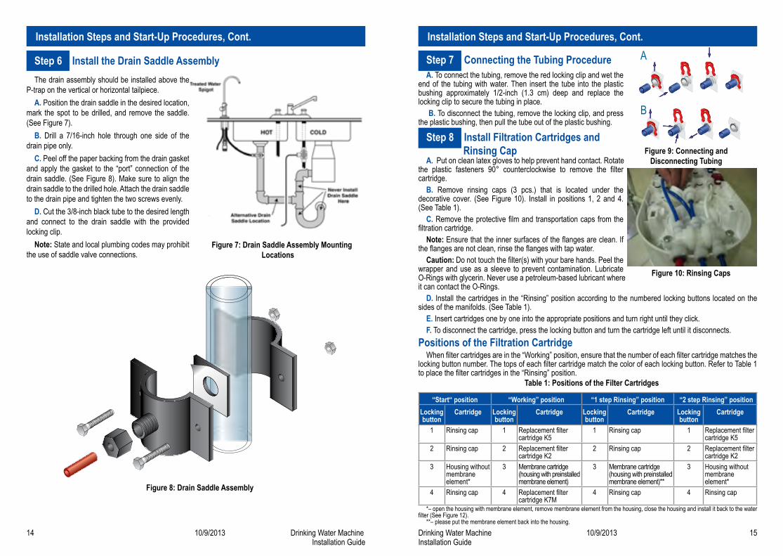
Step 6 Install the Drain Saddle AssemblyThe drain assembly should be installed above the
P-trap on the vertical or horizontal tailpiece.A. Position the drain saddle in the desired location,
mark the spot to be drilled, and remove the saddle.(See Figure 7).
B. Drill a 7/16-inch hole through one side of the drain pipe only.
C. Peel off the paper backing from the drain gasket and apply the gasket to the “port” connection of the drain saddle. (See Figure 8). Make sure to align the drain saddle to the drilled hole. Attach the drain saddle to the drain pipe and tighten the two screws evenly.
D. Cut the 3/8-inch black tube to the desired length and connect to the drain saddle with the provided locking clip.
Note: State and local plumbing codes may prohibit the use of saddle valve connections.
Figure 8: Drain Saddle Assembly
Step 7 Connecting the Tubing ProcedureA. To connect the tubing, remove the red locking clip and wet the
end of the tubing with water. Then insert the tube into the plastic bushing approximately 1/2-inch (1.3 cm) deep and replace the locking clip to secure the tubing in place.
B. To disconnect the tubing, remove the locking clip, and press the plastic bushing, then pull the tube out of the plastic bushing.
Step 8 Install Filtration Cartridges and Rinsing Cap
A. Put on clean latex gloves to help prevent hand contact. Rotate the plastic fasteners 90° counterclockwise to remove the filter cartridge.
B. Remove rinsing caps (3 pcs.) that is located under the decorative cover. (See Figure 10). Install in positions 1, 2 and 4. (See Table 1).
C. Remove the protective film and transportation caps from the filtration cartridge.
Note: Ensure that the inner surfaces of the flanges are clean. If the flanges are not clean, rinse the flanges with tap water.
Caution: Do not touch the filter(s) with your bare hands. Peel the wrapper and use as a sleeve to prevent contamination. Lubricate O-Rings with glycerin. Never use a petroleum-based lubricant where it can contact the O-Rings.
D. Install the cartridges in the “Rinsing” position according to the numbered locking buttons located on the sides of the manifolds. (See Table 1).
E. Insert cartridges one by one into the appropriate positions and turn right until they click.F. To disconnect the cartridge, press the locking button and turn the cartridge left until it disconnects.
Positions of the Filtration CartridgeWhen filter cartridges are in the “Working” position, ensure that the number of each filter cartridge matches the
locking button number. The tops of each filter cartridge match the color of each locking button. Refer to Table 1 to place the filter cartridges in the “Rinsing” position.
Table 1: Positions of the Filter Cartridges
“Start“ position “Working” position “1 step Rinsing” position “2 step Rinsing” positionLocking button
Cartridge Locking button
Cartridge Locking button
Cartridge Locking button
Cartridge
1 Rinsing cap 1 Replacement filter cartridge K5
1 Rinsing cap 1 Replacement filter cartridge K5
2 Rinsing cap 2 Replacement filter cartridge K2
2 Rinsing cap 2 Replacement filter cartridge K2
3 Housing without membrane element*
3 Membrane cartridge (housing with preinstalled membrane element)
3 Membrane cartridge (housing with preinstalled membrane element)**
3 Housing without membrane element*
4 Rinsing cap 4 Replacement filter cartridge K7M
4 Rinsing cap 4 Rinsing cap
*– open the housing with membrane element, remove membrane element from the housing, close the housing and install it back to the water filter (See Figure 12).
**– please put the membrane element back into the housing.
Installation Steps and Start-Up Procedures, Cont. Installation Steps and Start-Up Procedures, Cont.A
B
Figure 9: Connecting and Disconnecting Tubing
Figure 10: Rinsing Caps
Figure 7: Drain Saddle Assembly Mounting Locations
16 10/9/2013 Drinking Water MachineInstallation Guide
Drinking Water Machine 10/9/2013 17Installation Guide
Step 9 Start-up Procedure - Primary fillingA. Install cartridges in “Start” Position (See table 1).B. Close the clean water faucet.C. Turn on the incoming water supply valve.D. Wait until drain water flow stops (or not more than 5 minutes).E. Open the clean water faucet and let clean water flow (not more than 1 minute).F. Turn off the incoming water supply valve.
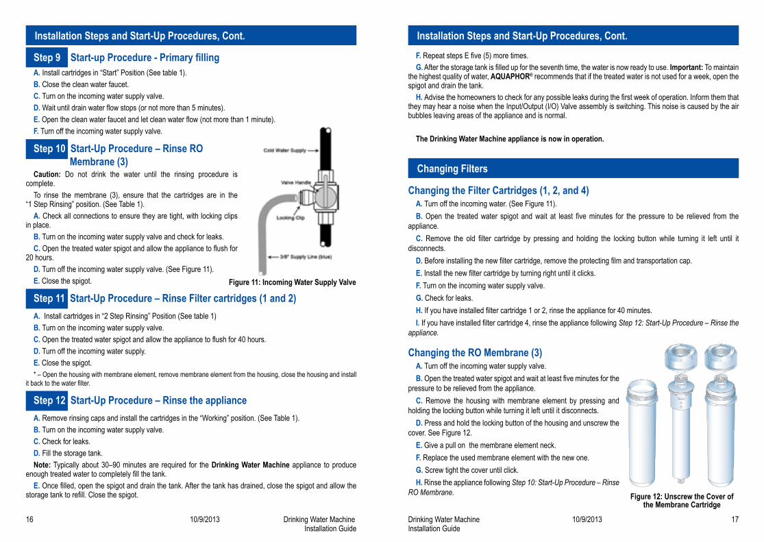
Step 10 Start-Up Procedure – Rinse RO Membrane (3)
Caution: Do not drink the water until the rinsing procedure is complete.
To rinse the membrane (3), ensure that the cartridges are in the “1 Step Rinsing” position. (See Table 1).
A. Check all connections to ensure they are tight, with locking clips in place.
B. Turn on the incoming water supply valve and check for leaks.C. Open the treated water spigot and allow the appliance to flush for
20 hours.D. Turn off the incoming water supply valve. (See Figure 11).E. Close the spigot.
Step 11 Start-Up Procedure – Rinse Filter cartridges (1 and 2)A. Install cartridges in “2 Step Rinsing” Position (See table 1)B. Turn on the incoming water supply valve.C. Open the treated water spigot and allow the appliance to flush for 40 hours.D. Turn off the incoming water supply.E. Close the spigot.* – Open the housing with membrane element, remove membrane element from the housing, close the housing and install
it back to the water filter.
Step 12 Start-Up Procedure – Rinse the applianceA. Remove rinsing caps and install the cartridges in the “Working” position. (See Table 1).B. Turn on the incoming water supply valve.C. Check for leaks.D. Fill the storage tank. Note: Typically about 30–90 minutes are required for the Drinking Water Machine appliance to produce
enough treated water to completely fill the tank.E. Once filled, open the spigot and drain the tank. After the tank has drained, close the spigot and allow the
storage tank to refill. Close the spigot.
Installation Steps and Start-Up Procedures, Cont. Installation Steps and Start-Up Procedures, Cont.
Figure 11: Incoming Water Supply Valve
Figure 12: Unscrew the Cover of the Membrane Cartridge
F. Repeat steps E five (5) more times.G. After the storage tank is filled up for the seventh time, the water is now ready to use. Important: To maintain
the highest quality of water, AQUAPHOR® recommends that if the treated water is not used for a week, open the spigot and drain the tank.
H. Advise the homeowners to check for any possible leaks during the first week of operation. Inform them that they may hear a noise when the Input/Output (I/O) Valve assembly is switching. This noise is caused by the air bubbles leaving areas of the appliance and is normal.
The Drinking Water Machine appliance is now in operation.
Changing the Filter Cartridges (1, 2, and 4)A. Turn off the incoming water. (See Figure 11).B. Open the treated water spigot and wait at least five minutes for the pressure to be relieved from the
appliance.C. Remove the old filter cartridge by pressing and holding the locking button while turning it left until it
disconnects.D. Before installing the new filter cartridge, remove the protecting film and transportation cap.E. Install the new filter cartridge by turning right until it clicks.F. Turn on the incoming water supply valve.G. Check for leaks.H. If you have installed filter cartridge 1 or 2, rinse the appliance for 40 minutes.I. If you have installed filter cartridge 4, rinse the appliance following Step 12: Start-Up Procedure – Rinse the
appliance.
Changing the RO Membrane (3)A. Turn off the incoming water supply valve.B. Open the treated water spigot and wait at least five minutes for the
pressure to be relieved from the appliance.C. Remove the housing with membrane element by pressing and
holding the locking button while turning it left until it disconnects.D. Press and hold the locking button of the housing and unscrew the
cover. See Figure 12.E. Give a pull on the membrane element neck.F. Replace the used membrane element with the new one.G. Screw tight the cover until click.H. Rinse the appliance following Step 10: Start-Up Procedure – Rinse
RO Membrane.
Changing Filters
18 10/9/2013 Drinking Water MachineInstallation Guide
Drinking Water Machine 10/9/2013 19Installation Guide
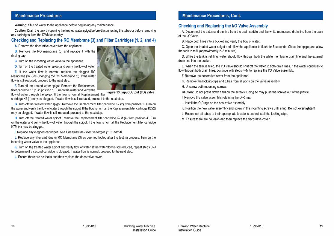
Figure 13: Input/Output (I/O) Valve
Warning: Shut off water to the appliance before beginning any maintenance.Caution: Drain the tank by opening the treated water spigot before disconnecting the tubes or before removing
any cartridges from the DWM assembly.Checking and Replacing the RO Membrane (3) and Filter Cartridges (1, 2, and 4)
A. Remove the decorative cover from the appliance.B. Remove the RO membrane (3) and replace it with the
rinsing cap.C. Turn on the incoming water valve to the appliance.D. Turn on the treated water spigot and verify the flow of water.E. If the water flow is normal, replace the clogged RO
Membrane (3). See Changing the RO Membrane (3). If the water flow is still reduced, proceed to the next step.
F. Turn off the treated water spigot. Remove the Replacement filter cartridge K5 (1) in position 1. Turn on the water and verify the flow of water through the spigot. If the flow is normal, Replacement filter cartridge K5 (1) may be clogged. If water flow is still reduced, proceed to the next step.
G. Turn off the treated water spigot. Remove the Replacement filter cartridge K2 (2) from position 2. Turn on the water and verify the flow of water through the spigot. If the flow is normal, the Replacement filter cartridge K2 (2) may be clogged. If water flow is still reduced, proceed to the next step.
H. Turn off the treated water spigot. Remove the Replacement filter cartridge K7M (4) from position 4. Turn on the water and verify the flow of water through the spigot. If the flow is normal, the Replacement filter cartridge K7M (4) may be clogged.
I. Replace any clogged cartridges. See Changing the Filter Cartridges (1, 2, and 4).J. Replace any filter cartridge or RO Membrane (3) as deemed fouled after the testing process. Turn on the
incoming water valve to the appliance.K. Turn on the treated water spigot and verify flow of water. If the water flow is still reduced, repeat steps C–J
to determine if a second cartridge is clogged. If water flow is normal, proceed to the next step.L. Ensure there are no leaks and then replace the decorative cover.
Checking and Replacing the I/O Valve AssemblyA. Disconnect the external drain line from the drain saddle and the white membrane drain line from the back
of the I/O Valve.B. Place both lines into a bucket and verify the flow of water.C. Open the treated water spigot and allow the appliance to flush for 5 seconds. Close the spigot and allow
the tank to refill (approximately 2–3 minutes).D. While the tank is refilling, water should flow through both the white membrane drain line and the external
drain line into the bucket.E. When the tank is filled, the I/O Valve should shut off the water to both drain lines. If the water continues to
flow through both drain lines, continue with steps F–M to replace the I/O Valve assembly.F. Remove the decorative cover from the appliance.G. Remove the locking clips and tubes from all ports on the valve assembly.H. Unscrew both mounting screws.Caution: Do not press down hard on the screws. Doing so may push the screws out of the plastic. I. Remove the valve assembly, retaining the O-Rings. J. Install the O-Rings on the new valve assemblyK. Position the new valve assembly and screw in the mounting screws until snug. Do not overtighten! L. Reconnect all tubes to their appropriate locations and reinstall the locking clips. M. Ensure there are no leaks and then replace the decorative cover.
Maintenance Procedures Maintenance Procedures, Cont.
20 10/9/2013 Drinking Water MachineInstallation Guide
Drinking Water Machine 10/9/2013 21Installation Guide
Checking and Replacing the Tank BladderA. Remove the decorative cover from the appliance.B. Remove the I/O Valve assembly.C. Disconnect the blue tube from the water fitting at top center of the storage tank.D. Using the Tank Flange Key provided by AQUAPHOR®, unscrew the plastic component on top of the storage
tank and inspect the O-Ring.E. Remove the tank bladder and inspect for damage.F. Replace or reinstall bladder, as required.G. Screw plastic head back onto storage tank.Note: Use glycerin on the O-Ring before reinstalling.H. Reconnect the blue tube to the water fitting at top center of the storage tank, and reinstall the I/O Valve
assembly.I. Ensure there are no leaks and then replace the decorative cover.
Water Leak Between the Storage Tank and the Top of the UnitA. Remove the decorative cover from the appliance.B. Examine seals for the storage tank:
1. Remove I/O Valve assembly.2. Disconnect the blue tube from the water fitting at top center of the storage tank.3. Unscrew the flange on the top of the storage tank with the Tank Flange Key.4. Examine the membrane neck for damage and inspect and/or replace the O-Ring.5. Lubricate the O-Ring and storage bladder neck with glycerin before re-installing the tank flange.6. Reconnect the blue tube to the water fitting at top center of the storage tank, and reinstall the I/O Valve
assembly.C. Ensure there are no leaks and then replace the decorative cover.
Unusual Sounds During OperationA. If the sound occurred right when the spigot was opened and the storage tank was full, check the membrane
flow restrictor in the I/O Valve assembly.1. Disconnect the blue tube from the water fitting at top center of the I/O Valve. (See Figure 13).2. Pull the Membrane Flow Restrictor out of the end of the blue tube and inspect and/or replace it.
B. If the sound is heard while the treated water spigot is closed and the tank is being filled or is coming from the bottom of the RO Membrane (3), check the flow restrictor. See Replacing the Membrane Flow Restrictor.
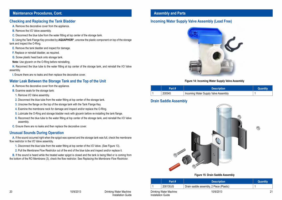
Incoming Water Supply Valve Assembly (Lead Free)
Figure 14: Incoming Water Supply Valve Assembly
Part # Description Quantity1 200545 Incoming Water Supply Valve Assembly 1
Drain Saddle Assembly
Figure 15: Drain Saddle Assembly
Part # Description Quantity1 200130JG Drain saddle assembly, 2 Piece (Plastic) 1
Maintenance Procedures, Cont. Assembly and Parts
22 10/9/2013 Drinking Water MachineInstallation Guide
Drinking Water Machine 10/9/2013 23Installation Guide
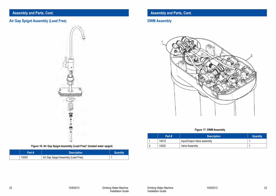
Air Gap Spigot Assembly (Lead Free)
Figure 16: Air Gap Spigot Assembly (Lead Free)* (treated water spigot)
Part # Description Quantity10005 Air Gap Spigot Assembly (Lead Free) 1
DWM Assembly
Figure 17: DWM Assembly
Part # Description Quantity1 10015 Input/Output Valve assembly 12 10020 Valve Assembly 1
Assembly and Parts, Cont. Assembly and Parts, Cont.
24 10/9/2013 Drinking Water MachineInstallation Guide
Drinking Water Machine 10/9/2013 25Installation Guide
If the appliance experiences difficulties, use the Appliance Shutoff Valve to shut off the incoming water to the appliance.
Problem Possible Cause SolutionNo water, not enough water, or low water flow
Incoming water supply valve is turned off
Turn on incoming water supply valve
Low incoming water pressure Verify pressure is above 28 psi; install a booster pump if needed
Capacity is exhausted Allow time for the appliance to replen-ish the storage tank
Plumbing restriction Check connections and tubes for obstructions
Filters (1, 2, and 4) or RO mem-brane (3) is clogged
See Maintenance Procedures
I/O Valve is inoperative See Maintenance ProceduresUnexpected flow in drain line I/O Valve is inoperative See Maintenance ProceduresNo drain flow Filters (1, 2, and 4) or RO mem-
brane (3) is cloggedSee Maintenance Procedures
Flow restrictor is inoperative See Maintenance ProceduresBad tasting water Replacement filter cartridge K7M (4)
is exhaustedSee Maintenance Procedures
Newly replaced Replacement filter cartridge K7M (4) is not flushed completely
Open the treated water spigot and drain the storage tank once. Flush one or two tanks of treated water through the postfilter (4)
Problem with the tank bladder See Maintenance ProceduresCloudy water and/or ice cubes
Dissolved air in incoming water supply
Problem clears up as the condition of the incoming water changes. Letting water stand will allow the dissolved air to dissipate
Leaking water from appliance Tube is not fully inserted into a connection
Make sure the tube is at least 1/2-inch into the connection and install the locking clip
A cartridge is not installed correctly Ensure that all four cartridges are locked into place
Water is sitting in the top of the appliance
Verify that no water is in the top of the unit under the decorative cover. See Maintenance Procedures
Spigot-valve leaks Valve seat is defective Replace the spigot assemblyAir gap overflows Debris is lodged in 3/8-inch drain
lineDisconnect the tube from the drain saddle and clean out the debris or replace the drain line
Broken handle or spout Fatigue or misuse Replace the spigot assemblyUnusual sounds during operation
Problem with one of the restrictors See Maintenance Procedures
Troubleshooting
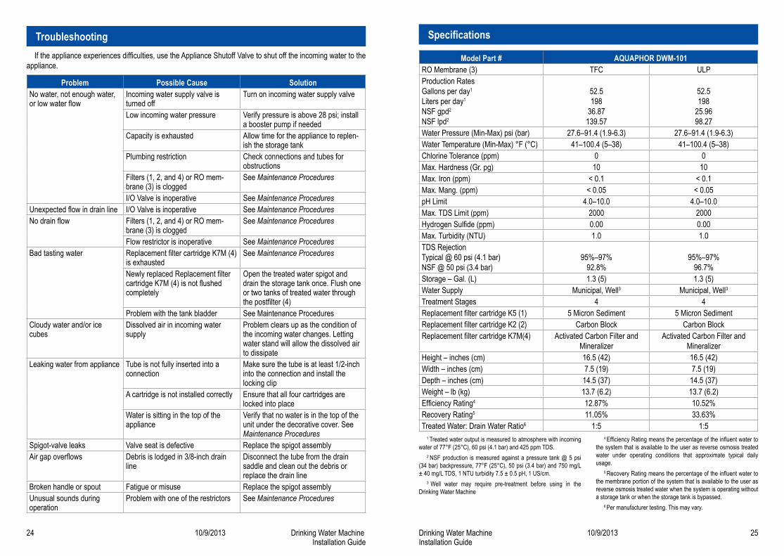
Model Part # AQUAPHOR DWM-101RO Membrane (3) TFC ULPProduction Rates Gallons per day1 Liters per day1
NSF gpd2 NSF lpd2
52.5 198
36.87 139.57
52.5 198
25.96 98.27
Water Pressure (Min-Max) psi (bar) 27.6–91.4 (1.9-6.3) 27.6–91.4 (1.9-6.3)Water Temperature (Min-Max) °F (°C) 41–100.4 (5–38) 41–100.4 (5–38)Chlorine Tolerance (ppm) 0 0Max. Hardness (Gr. pg) 10 10Max. Iron (ppm) < 0.1 < 0.1Max. Mang. (ppm) < 0.05 < 0.05pH Limit 4.0–10.0 4.0–10.0Max. TDS Limit (ppm) 2000 2000Hydrogen Sulfide (ppm) 0.00 0.00Max. Turbidity (NTU) 1.0 1.0TDS Rejection Typical @ 60 psi (4.1 bar) NSF @ 50 psi (3.4 bar)
95%–97% 92.8%
95%–97% 96.7%
Storage – Gal. (L) 1.3 (5) 1.3 (5)Water Supply Municipal, Well3 Municipal, Well3Treatment Stages 4 4Replacement filter cartridge K5 (1) 5 Micron Sediment 5 Micron SedimentReplacement filter cartridge K2 (2) Carbon Block Carbon BlockReplacement filter cartridge K7M(4) Activated Carbon Filter and
MineralizerActivated Carbon Filter and
MineralizerHeight – inches (cm) 16.5 (42) 16.5 (42)Width – inches (cm) 7.5 (19) 7.5 (19)Depth – inches (cm) 14.5 (37) 14.5 (37)Weight – lb (kg) 13.7 (6.2) 13.7 (6.2)Efficiency Rating4 12.87% 10.52%Recovery Rating5 11.05% 33.63%Treated Water: Drain Water Ratio6 1:5 1:5
Specifications
1 Treated water output is measured to atmosphere with incoming water of 77°F (25°C), 60 psi (4.1 bar) and 425 ppm TDS.
2 NSF production is measured against a pressure tank @ 5 psi (34 bar) backpressure, 77°F (25°C), 50 psi (3.4 bar) and 750 mg/L ± 40 mg/L TDS, 1 NTU turbidity 7.5 ± 0.5 pH, 1 US/cm.
3 Well water may require pre-treatment before using in the Drinking Water Machine
4 Efficiency Rating means the percentage of the influent water to the system that is available to the user as reverse osmosis treated water under operating conditions that approximate typical daily usage.
5 Recovery Rating means the percentage of the influent water to the membrane portion of the system that is available to the user as reverse osmosis treated water when the system is operating without a storage tank or when the storage tank is bypassed.
6 Per manufacturer testing. This may vary.
26 10/9/2013 Drinking Water MachineInstallation Guide
Drinking Water Machine 10/9/2013 27Installation Guide
NotesNotes
P.O. Box 298, Groveport, OH 43125 Phone: 614-836-9422. Fax: 614-836-9876
© 2013
Drinking Water MachineAQUAPHOR DWM-101