Embed Size (px)
Citation preview
Velvet Drive In-Line and V-Drive Transmission
90-864260400 AUGUST 2009 Page 8A-1
8A
DrivesSection 8A - Velvet Drive In-Line and V-Drive Transmission
Table of Contents
Identification.......................................................................8A-2Specifications.....................................................................8A-2
Operating Specifications.............................................8A-2Ratios and Part Numbers...........................................8A-2Fluid Specifications.....................................................8A-3Tools...........................................................................8A-3Pressure Specifications..............................................8A-3Torque Specifications.................................................8A-3
Precautions........................................................................8A-3Transmission and Related Parts........................................8A-5Transmission and Propeller Rotation.................................8A-8
Identification................................................................8A-8General Information....................................................8A-8
Fluid Level..........................................................................8A-9Checking.....................................................................8A-9
Removal...........................................................................8A-12Installation........................................................................8A-13Shift Lever Installation......................................................8A-13Shift Control and Cables..................................................8A-14
Transmission Shift Lever and Shift Cable Bracket. . .8A-14Installation and Adjustment (Excluding Scorpion Models)..................................................................................8A-15Scorpion Shift Cable Installation and Adjustment.....8A-18
Pressure Test...................................................................8A-20Transmission Repair Information.....................................8A-21
Velvet Drive In-Line and V-Drive Transmission
Page 8A-2 90-864260400 AUGUST 2009
Lubricants, Sealants, AdhesivesTube Ref No. Description Where Used Part No.
19 Perfect Seal Bushing threadsElbow fitting threads 92-34227Q02
91 Engine Coupler SplineGrease Transmission input shaft splines and engine drive plate splines 92-802869A 1
95 2-4-C Marine Lubricant withTeflon Transmission shift lever, poppet ball, spring, and shift lever holes 92-802859A 1
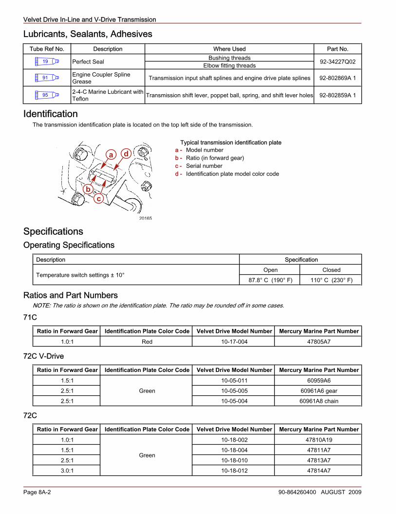
IdentificationThe transmission identification plate is located on the top left side of the transmission.
Typical transmission identification platea - Model numberb - Ratio (in forward gear)c - Serial numberd - Identification plate model color code
SpecificationsOperating Specifications
Description Specification
Temperature switch settings ± 10°Open Closed
87.8° C (190° F) 110° C (230° F)
Ratios and Part NumbersNOTE: The ratio is shown on the identification plate. The ratio may be rounded off in some cases.
71C
Ratio in Forward Gear Identification Plate Color Code Velvet Drive Model Number Mercury Marine Part Number
1.0:1 Red 10‑17‑004 47805A7
72C V-Drive
Ratio in Forward Gear Identification Plate Color Code Velvet Drive Model Number Mercury Marine Part Number
1.5:1Green
10‑05‑011 60959A62.5:1 10‑05‑005 60961A6 gear2.5:1 10‑05‑004 60961A8 chain
72C
Ratio in Forward Gear Identification Plate Color Code Velvet Drive Model Number Mercury Marine Part Number
1.0:1
Green
10‑18‑002 47810A191.5:1 10‑18‑004 47811A72.5:1 10‑18‑010 47813A73.0:1 10‑18‑012 47814A7
a d
bc
20165
Velvet Drive In-Line and V-Drive Transmission
90-864260400 AUGUST 2009 Page 8A-3
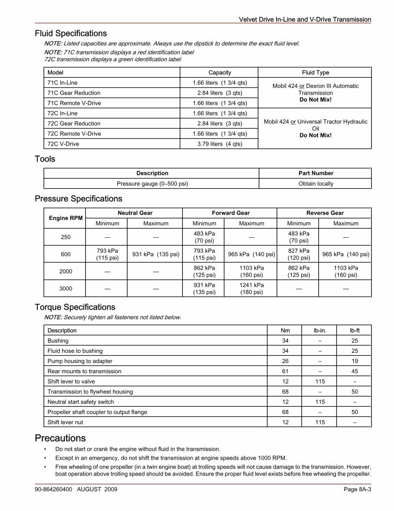
Fluid SpecificationsNOTE: Listed capacities are approximate. Always use the dipstick to determine the exact fluid level.NOTE: 71C transmission displays a red identification label72C transmission displays a green identification label
Model Capacity Fluid Type71C In‑Line 1.66 liters (1 3/4 qts) Mobil 424 or Dexron III Automatic
TransmissionDo Not Mix!
71C Gear Reduction 2.84 liters (3 qts)71C Remote V‑Drive 1.66 liters (1 3/4 qts)72C In‑Line 1.66 liters (1 3/4 qts)
Mobil 424 or Universal Tractor HydraulicOil
Do Not Mix!
72C Gear Reduction 2.84 liters (3 qts)72C Remote V‑Drive 1.66 liters (1 3/4 qts)72C V‑Drive 3.79 liters (4 qts)
ToolsDescription Part Number
Pressure gauge (0–500 psi) Obtain locally
Pressure Specifications
Engine RPMNeutral Gear Forward Gear Reverse Gear
Minimum Maximum Minimum Maximum Minimum Maximum
250 — — 483 kPa(70 psi) — 483 kPa
(70 psi) —
600 793 kPa(115 psi) 931 kPa (135 psi) 793 kPa
(115 psi) 965 kPa (140 psi) 827 kPa(120 psi) 965 kPa (140 psi)
2000 — — 862 kPa(125 psi)
1103 kPa(160 psi)
862 kPa(125 psi)
1103 kPa(160 psi)
3000 — — 931 kPa(135 psi)
1241 kPa(180 psi) — —
Torque SpecificationsNOTE: Securely tighten all fasteners not listed below.
Description Nm lb‑in. lb‑ftBushing 34 – 25Fluid hose to bushing 34 – 25Pump housing to adapter 26 – 19Rear mounts to transmission 61 – 45Shift lever to valve 12 115 –Transmission to flywheel housing 68 – 50Neutral start safety switch 12 115 –Propeller shaft coupler to output flange 68 – 50Shift lever nut 12 115 –
Precautions• Do not start or crank the engine without fluid in the transmission.• Except in an emergency, do not shift the transmission at engine speeds above 1000 RPM.• Free wheeling of one propeller (in a twin engine boat) at trolling speeds will not cause damage to the transmission. However,
boat operation above trolling speed should be avoided. Ensure the proper fluid level exists before free wheeling the propeller.
Velvet Drive In-Line and V-Drive Transmission
Page 8A-4 90-864260400 AUGUST 2009
• Do not paint the shift lever poppet ball and spring. The paint will prevent the detent from functioning correctly.• Always replace the oil cooler and the hoses after a transmission failure or prior to installing a new or rebuilt transmission.
Metallic particles from a failure tend to collect in the cooler and hoses and will gradually flow back into the fluid system anddamage the transmission.
• Always use the specified oil cooler, hoses, and fittings. The hoses must be at least 10.5 mm (13/32 in.) I.D. The oil cooler,hoses, and fittings must be sized correctly to maintain the transmission fluid at 60–88° C (140–190° F).
• Adjust the shift cables so the remote control and the shift cable position the shift lever correctly.• Do not change propeller rotation by reversing the shift lever.• Perform the engine alignment with the boat at rest in the water.
Velvet Drive In-Line and V-Drive Transmission
90-864260400 AUGUST 2009 Page 8A-5
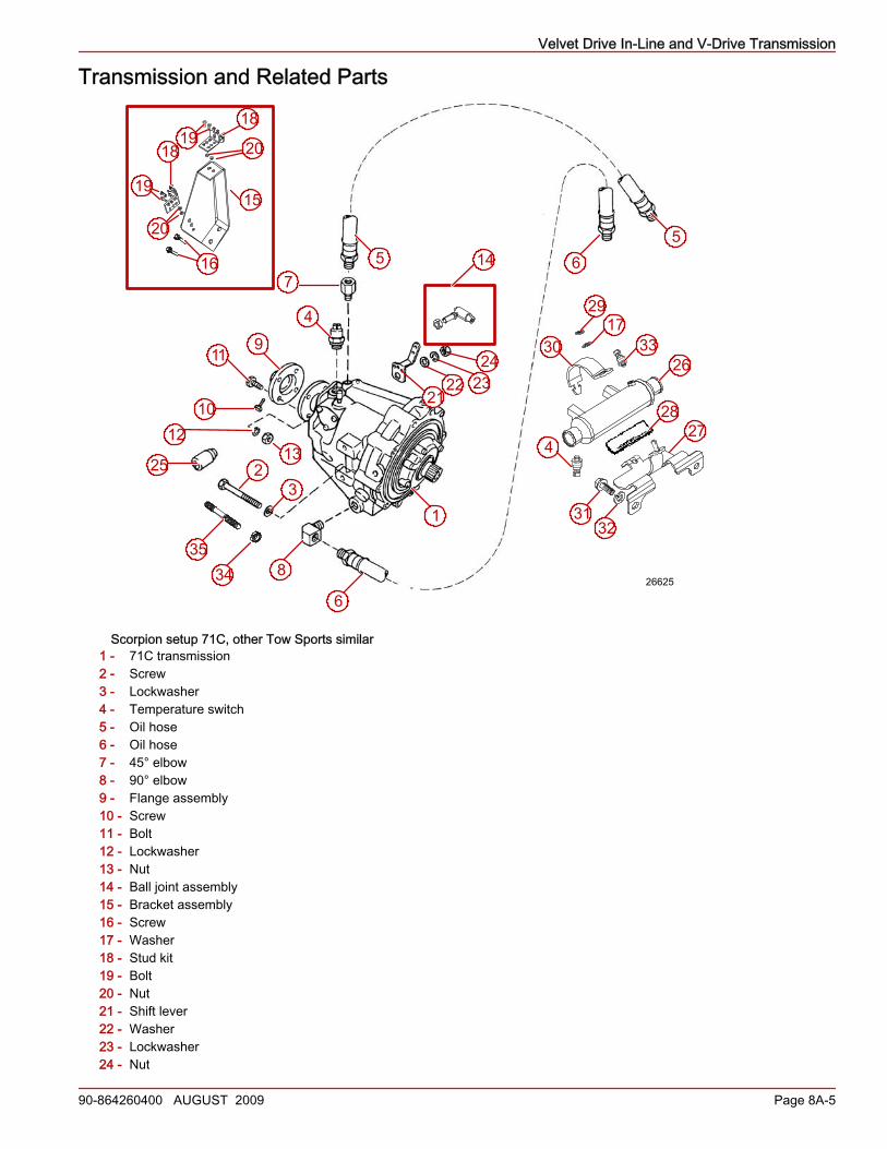
Transmission and Related Parts
Scorpion setup 71C, other Tow Sports similar1 - 71C transmission2 - Screw3 - Lockwasher4 - Temperature switch5 - Oil hose6 - Oil hose7 - 45° elbow8 - 90° elbow9 - Flange assembly10 - Screw11 - Bolt12 - Lockwasher13 - Nut14 - Ball joint assembly15 - Bracket assembly16 - Screw17 - Washer18 - Stud kit19 - Bolt20 - Nut21 - Shift lever22 - Washer23 - Lockwasher24 - Nut
2728
29
30
3132
33
4
56
17
26
1
10
15
25
8
9
23
75
4
11
1213
3435
6
1416
20
19
18 201918
26625
2122 23
24

Velvet Drive In-Line and V-Drive Transmission
Page 8A-6 90-864260400 AUGUST 2009
25 - Neutral safety switch26 - Oil cooler27 - Cooler bracket28 - Cooler bracket pad29 - Nut30 - Cooler clamp31 - Screw32 - Lockwasher33 - Pressure sensor34 - Nut35 - Stud
Velvet Drive In-Line and V-Drive Transmission
90-864260400 AUGUST 2009 Page 8A-7
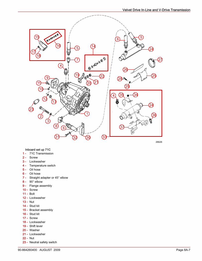
Inboard set up 71C1 - 71C Transmission2 - Screw3 - Lockwasher4 - Temperature switch5 - Oil hose6 - Oil hose7 - Straight adapter or 45° elbow8 - 90° elbow9 - Flange assembly10 - Screw11 - Bolt12 - Lockwasher13 - Nut14 - Stud kit15 - Bracket assembly16 - Stud kit17 - Screw18 - Lockwasher19 - Shift lever20 - Washer21 - Lockwasher22 - Nut23 - Neutral safety switch
27
28
29
3031 32
12
3
4
56
10
11
12
8
9
13
14
19
2122
23
24
25
26
5
7
6
20
3435
36
4
24
15
16
1718
37
3326626
Velvet Drive In-Line and V-Drive Transmission
Page 8A-8 90-864260400 AUGUST 2009
24 - Oil cooler25 - Cooler bracket26 - Cooler bracket pad27 - Cooler clamp28 - Screw29 - Lockwasher30 - Clamp, double hose31 - Screw32 - Lockwasher33 - New cooler bracket assembly34 - Nut35 - Cooler clamp36 - Pressure sensor37 - Cooler bracket
Transmission and Propeller RotationIdentification
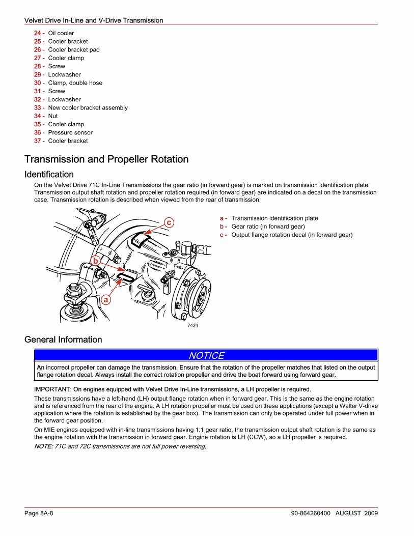
On the Velvet Drive 71C In‑Line Transmissions the gear ratio (in forward gear) is marked on transmission identification plate.Transmission output shaft rotation and propeller rotation required (in forward gear) are indicated on a decal on the transmissioncase. Transmission rotation is described when viewed from the rear of transmission.
a - Transmission identification plateb - Gear ratio (in forward gear)c - Output flange rotation decal (in forward gear)
General Information
NOTICEAn incorrect propeller can damage the transmission. Ensure that the rotation of the propeller matches that listed on the outputflange rotation decal. Always install the correct rotation propeller and drive the boat forward using forward gear.
IMPORTANT: On engines equipped with Velvet Drive In‑Line transmissions, a LH propeller is required.These transmissions have a left‑hand (LH) output flange rotation when in forward gear. This is the same as the engine rotationand is referenced from the rear of the engine. A LH rotation propeller must be used on these applications (except a Walter V‑driveapplication where the rotation is established by the gear box). The transmission can only be operated under full power when inthe forward gear position.On MIE engines equipped with in‑line transmissions having 1:1 gear ratio, the transmission output shaft rotation is the same asthe engine rotation with the transmission in forward gear. Engine rotation is LH (CCW), so a LH propeller is required.NOTE: 71C and 72C transmissions are not full power reversing.
c
a
b
7424
Velvet Drive In-Line and V-Drive Transmission
90-864260400 AUGUST 2009 Page 8A-9
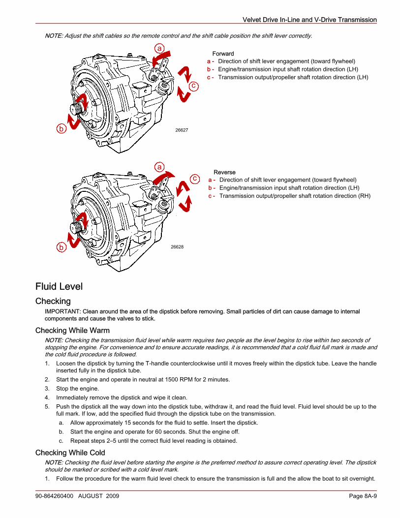
NOTE: Adjust the shift cables so the remote control and the shift cable position the shift lever correctly.
Forwarda - Direction of shift lever engagement (toward flywheel)b - Engine/transmission input shaft rotation direction (LH)c - Transmission output/propeller shaft rotation direction (LH)
Reversea - Direction of shift lever engagement (toward flywheel)b - Engine/transmission input shaft rotation direction (LH)c - Transmission output/propeller shaft rotation direction (RH)
Fluid LevelChecking
IMPORTANT: Clean around the area of the dipstick before removing. Small particles of dirt can cause damage to internalcomponents and cause the valves to stick.
Checking While WarmNOTE: Checking the transmission fluid level while warm requires two people as the level begins to rise within two seconds ofstopping the engine. For convenience and to ensure accurate readings, it is recommended that a cold fluid full mark is made andthe cold fluid procedure is followed.1. Loosen the dipstick by turning the T‑handle counterclockwise until it moves freely within the dipstick tube. Leave the handle
inserted fully in the dipstick tube.2. Start the engine and operate in neutral at 1500 RPM for 2 minutes.3. Stop the engine.4. Immediately remove the dipstick and wipe it clean.5. Push the dipstick all the way down into the dipstick tube, withdraw it, and read the fluid level. Fluid level should be up to the
full mark. If low, add the specified fluid through the dipstick tube on the transmission.a. Allow approximately 15 seconds for the fluid to settle. Insert the dipstick.b. Start the engine and operate for 60 seconds. Shut the engine off.c. Repeat steps 2–5 until the correct fluid level reading is obtained.
Checking While ColdNOTE: Checking the fluid level before starting the engine is the preferred method to assure correct operating level. The dipstickshould be marked or scribed with a cold level mark.1. Follow the procedure for the warm fluid level check to ensure the transmission is full and the allow the boat to sit overnight.
a
c
b 26627
ac
b 26628
Velvet Drive In-Line and V-Drive Transmission
Page 8A-10 90-864260400 AUGUST 2009
IMPORTANT: Push the dipstick all the way down into the dipstick tube when checking the fluid level.2. Remove the dipstick, wipe clean, and insert.3. Remove the dipstick, observe the fluid level, and mark the cold fluid level.4. Install the dipstick and tighten. Do not overtighten.5. Future checks can be made when the transmission fluid is cold:
a. Remove the dipstick and wipe it clean.b. Insert the dipstick and remove to observe the fluid level.
Refer to Section 1–Maintenance.
ChangingIMPORTANT: Do not start or crank the engine without fluid in the transmission.When servicing the transmission, change the fluid, flush the fluid lines and replace the fluid cooler.
NOTICEDischarge of oil, coolant, or other engine/drive fluids into the environment is restricted by law. Use caution not to spill oil, coolant,or other fluids into the environment when using or servicing your boat. Be aware of the local restrictions governing the disposalor recycling of waste, and contain and dispose of fluids as required.
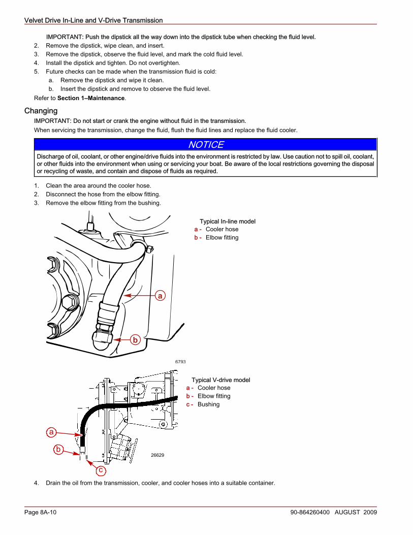
1. Clean the area around the cooler hose.2. Disconnect the hose from the elbow fitting.3. Remove the elbow fitting from the bushing.
Typical In-line modela - Cooler hoseb - Elbow fitting
Typical V-drive modela - Cooler hoseb - Elbow fittingc - Bushing
4. Drain the oil from the transmission, cooler, and cooler hoses into a suitable container.
a
b
6793
b
c
a
26629
Velvet Drive In-Line and V-Drive Transmission
90-864260400 AUGUST 2009 Page 8A-11
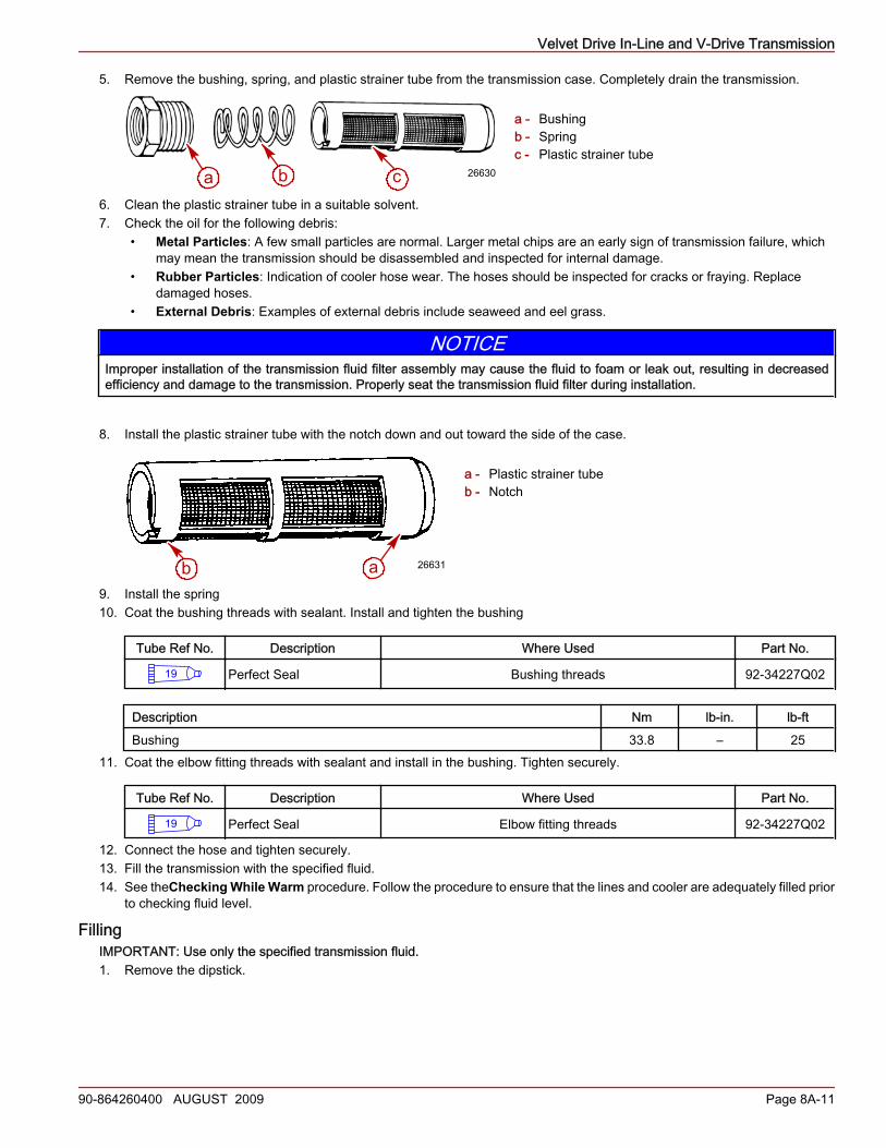
5. Remove the bushing, spring, and plastic strainer tube from the transmission case. Completely drain the transmission.
a - Bushingb - Springc - Plastic strainer tube
6. Clean the plastic strainer tube in a suitable solvent.7. Check the oil for the following debris:
• Metal Particles: A few small particles are normal. Larger metal chips are an early sign of transmission failure, whichmay mean the transmission should be disassembled and inspected for internal damage.
• Rubber Particles: Indication of cooler hose wear. The hoses should be inspected for cracks or fraying. Replacedamaged hoses.
• External Debris: Examples of external debris include seaweed and eel grass.
NOTICEImproper installation of the transmission fluid filter assembly may cause the fluid to foam or leak out, resulting in decreasedefficiency and damage to the transmission. Properly seat the transmission fluid filter during installation.
8. Install the plastic strainer tube with the notch down and out toward the side of the case.
a - Plastic strainer tubeb - Notch
9. Install the spring10. Coat the bushing threads with sealant. Install and tighten the bushing
Tube Ref No. Description Where Used Part No.
19 Perfect Seal Bushing threads 92-34227Q02
Description Nm lb‑in. lb‑ftBushing 33.8 – 25
11. Coat the elbow fitting threads with sealant and install in the bushing. Tighten securely.
Tube Ref No. Description Where Used Part No.
19 Perfect Seal Elbow fitting threads 92-34227Q02
12. Connect the hose and tighten securely.13. Fill the transmission with the specified fluid.14. See theChecking While Warm procedure. Follow the procedure to ensure that the lines and cooler are adequately filled prior
to checking fluid level.
FillingIMPORTANT: Use only the specified transmission fluid.1. Remove the dipstick.
b ca 26630
b a 26631
Velvet Drive In-Line and V-Drive Transmission
Page 8A-12 90-864260400 AUGUST 2009
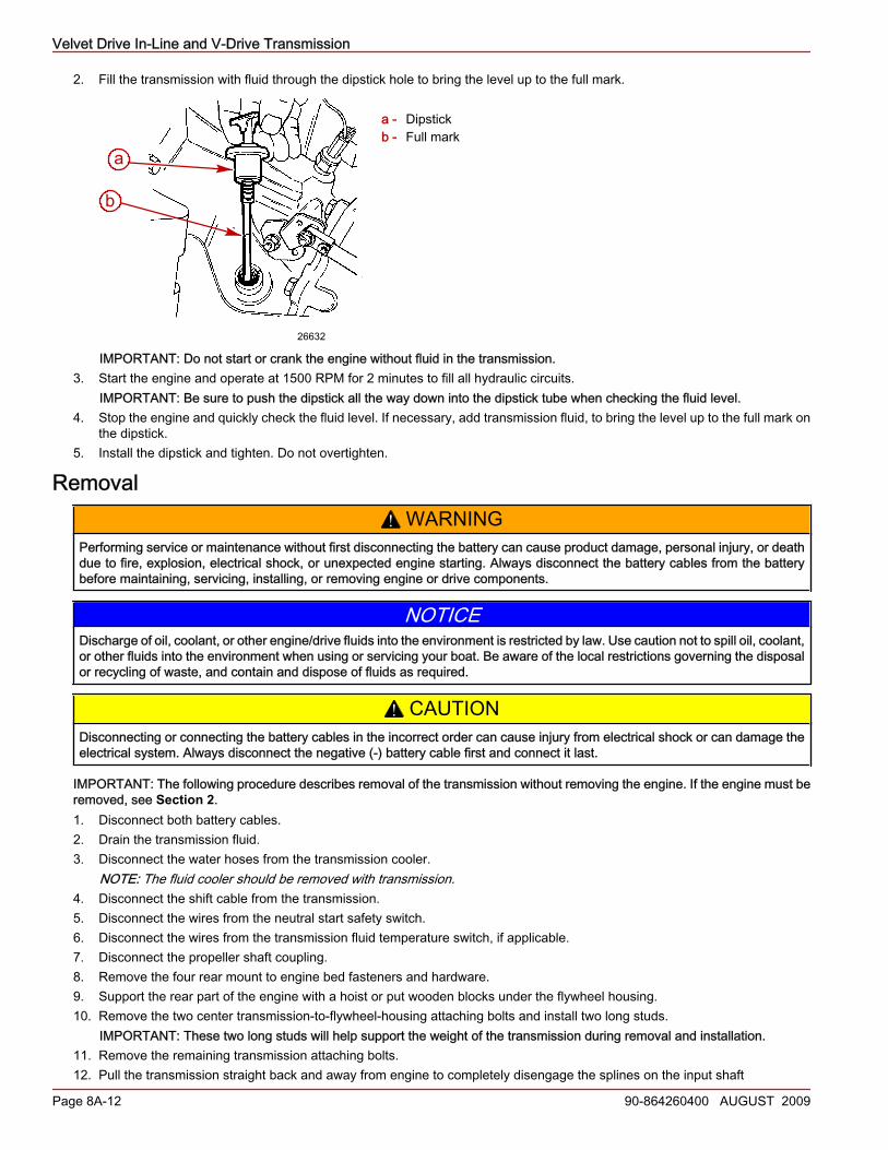
2. Fill the transmission with fluid through the dipstick hole to bring the level up to the full mark.
a - Dipstickb - Full mark
IMPORTANT: Do not start or crank the engine without fluid in the transmission.3. Start the engine and operate at 1500 RPM for 2 minutes to fill all hydraulic circuits.
IMPORTANT: Be sure to push the dipstick all the way down into the dipstick tube when checking the fluid level.4. Stop the engine and quickly check the fluid level. If necessary, add transmission fluid, to bring the level up to the full mark on
the dipstick.5. Install the dipstick and tighten. Do not overtighten.
Removal! WARNING
Performing service or maintenance without first disconnecting the battery can cause product damage, personal injury, or deathdue to fire, explosion, electrical shock, or unexpected engine starting. Always disconnect the battery cables from the batterybefore maintaining, servicing, installing, or removing engine or drive components.
NOTICEDischarge of oil, coolant, or other engine/drive fluids into the environment is restricted by law. Use caution not to spill oil, coolant,or other fluids into the environment when using or servicing your boat. Be aware of the local restrictions governing the disposalor recycling of waste, and contain and dispose of fluids as required.
! CAUTIONDisconnecting or connecting the battery cables in the incorrect order can cause injury from electrical shock or can damage theelectrical system. Always disconnect the negative (‑) battery cable first and connect it last.
IMPORTANT: The following procedure describes removal of the transmission without removing the engine. If the engine must beremoved, see Section 2.1. Disconnect both battery cables.2. Drain the transmission fluid.3. Disconnect the water hoses from the transmission cooler.
NOTE: The fluid cooler should be removed with transmission.4. Disconnect the shift cable from the transmission.5. Disconnect the wires from the neutral start safety switch.6. Disconnect the wires from the transmission fluid temperature switch, if applicable.7. Disconnect the propeller shaft coupling.8. Remove the four rear mount to engine bed fasteners and hardware.9. Support the rear part of the engine with a hoist or put wooden blocks under the flywheel housing.10. Remove the two center transmission‑to‑flywheel‑housing attaching bolts and install two long studs.
IMPORTANT: These two long studs will help support the weight of the transmission during removal and installation.11. Remove the remaining transmission attaching bolts.12. Pull the transmission straight back and away from engine to completely disengage the splines on the input shaft
a
b
26632
Velvet Drive In-Line and V-Drive Transmission
90-864260400 AUGUST 2009 Page 8A-13
13. Carefully lift out the transmission.
Installation1. Apply lubricant to the transmission input shaft splines and the engine drive plate splines.
Tube Ref No. Description Where Used Part No.
91 Engine Coupler SplineGrease
Transmission input shaft splines and engine drive platesplines 92-802869A 1
2. If removed, install the rear engine mounting brackets and tighten to specification.
Description Nm lb‑in. lb‑ftRear mounts to transmission fasteners 61 – 45
3. Using a suitable hoist, position the transmission in the boat and align the transmission input shaft splines with the engine driveplate splines.IMPORTANT: Two long studs will help support the weight of the transmission during removal and installation.
4. Install two long studs in the two center transmission to flywheel housing attaching bolt holes.5. Slide the transmission into place and secure with bolts.6. Remove the two long studs and install the remaining two bolts. Tighten all fasteners.
Description Nm lb‑in. lb‑ftTransmission to flywheel housing fasteners 68 – 50
7. Use a hoist to raise the engine and transmission to remove blocks (if used).8. Lower the assembly to the engine bed.9. Relieve the hoist tension and fasten the rear engine mounts to the engine bed. Tighten the bolts.10. Connect the wires to the neutral‑start safety switch.11. Connect the wires to the fluid temperature switch, if applicable.12. Connect the the water hoses to the transmission cooler and tighten the hose clamps.
IMPORTANT: Improper shift cable adjustment can cause premature clutch failure.13. Connect and adjust the shift cables. Refer toInstallation and Adjustment.14. Check the engine final alignment. Refer toSection 2.
IMPORTANT: Do not start or crank the engine without fluid in the transmission.15. Refill the transmission with the specified fluid.16. Connect both battery cables. Tighten the clamp.17. Start the engine and check for leaks.18. Check the fluid level.
Shift Lever InstallationIMPORTANT: The warranty will be jeopardized if the shift lever poppet spring or ball is permanently removed, or if the shift leveris changed in any manner, or repositioned, or if the linkage between the remote control and the transmission shift lever does nothave sufficient travel in both directions.The shift lever and related parts must be assembled as shown.1. Lubricate the poppet ball, spring, and holes in the shift lever with lubricant.2. Install the poppet spring and ball. Retain the ball by placing the shift lever on the shaft.3. Install the flat washer, lockwasher and nut on the shaft.
Velvet Drive In-Line and V-Drive Transmission
Page 8A-14 90-864260400 AUGUST 2009
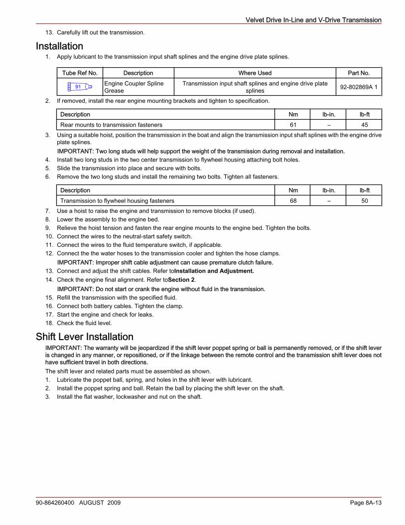
4. Tighten the nut.
Typical Shift Levera - Nutb - Lockwasherc - Flat washerd - Shift levere - Poppet ballf - Poppet spring
Tube Ref No. Description Where Used Part No.
95 2-4-C Marine Lubricantwith Teflon
Transmission shift lever, poppet ball, spring, and shift leverholes 92-802859A 1
Description Nm lb‑in. lb‑ftShift lever mounting nut 12 115 –
5. After installation, move the shift lever through the forward, neutral and reverse positions. No more than the finger‑tip effortshould be required. If the valve binds, the cause of the binding must be found and corrected.
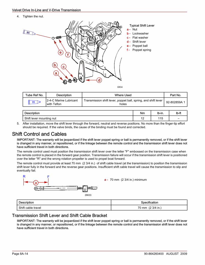
Shift Control and CablesIMPORTANT: The warranty will be jeopardized if the shift lever poppet spring or ball is permanently removed, or if the shift leveris changed in any manner, or repositioned, or if the linkage between the remote control and the transmission shift lever does nothave sufficient travel in both directions.The remote control used must position the transmission shift lever over the letter "F" embossed on the transmission case whenthe remote control is placed in the forward gear position. Transmission failure will occur if the transmission shift lever is positionedover the letter "R" and the wrong rotation propeller is used to propel boat forward.The remote control must provide at least 70 mm (2 3/4 in.) of shift cable travel (at the transmission) to position the transmissionshift lever fully in the forward and the reverse gear positions. Insufficient shift cable travel will cause the transmission to slip andeventually fail.
a - 70 mm (2 3/4 in.) minimum
Description SpecificationShift cable travel 70 mm (2 3/4 in.)
Transmission Shift Lever and Shift Cable BracketIMPORTANT: The warranty will be jeopardized if the shift lever poppet spring or ball is permanently removed, or if the shift leveris changed in any manner, or repositioned, or if the linkage between the remote control and the transmission shift lever does nothave sufficient travel in both directions.
e f
cb
a
d6804
95
aR F
26633
Velvet Drive In-Line and V-Drive Transmission
90-864260400 AUGUST 2009 Page 8A-15
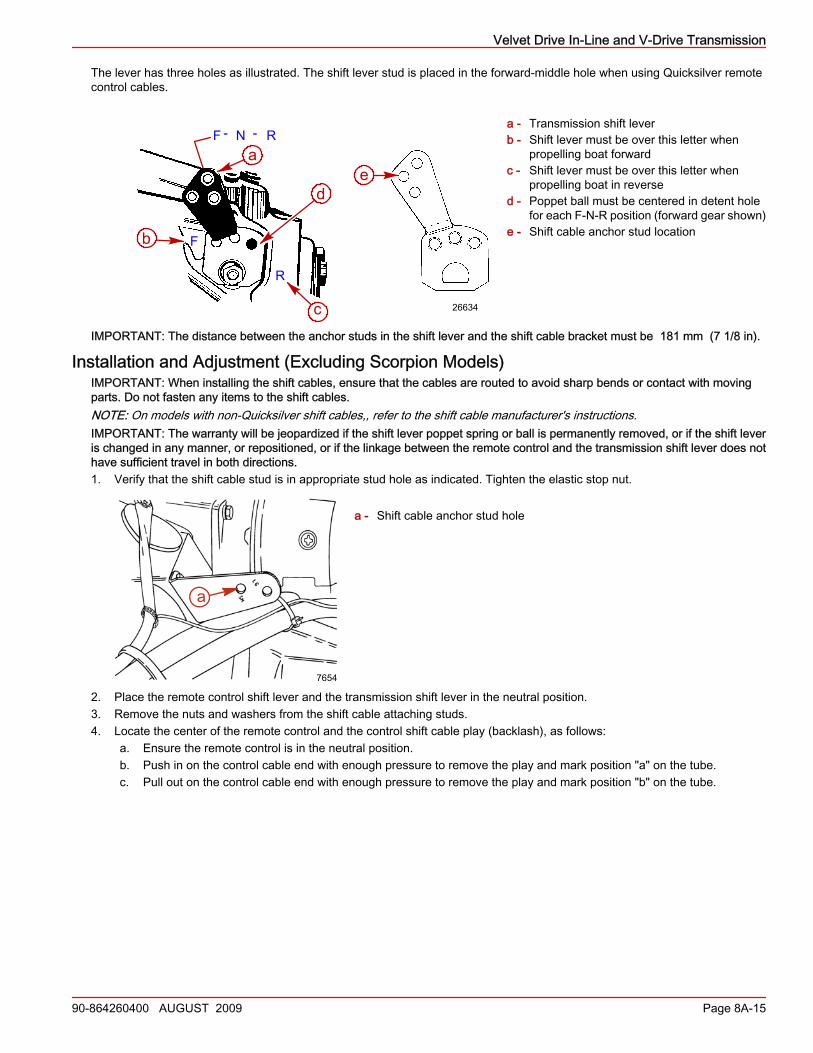
The lever has three holes as illustrated. The shift lever stud is placed in the forward‑middle hole when using Quicksilver remotecontrol cables.
a - Transmission shift leverb - Shift lever must be over this letter when
propelling boat forwardc - Shift lever must be over this letter when
propelling boat in reversed - Poppet ball must be centered in detent hole
for each F‑N‑R position (forward gear shown)e - Shift cable anchor stud location
IMPORTANT: The distance between the anchor studs in the shift lever and the shift cable bracket must be 181 mm (7 1/8 in).
Installation and Adjustment (Excluding Scorpion Models)IMPORTANT: When installing the shift cables, ensure that the cables are routed to avoid sharp bends or contact with movingparts. Do not fasten any items to the shift cables.NOTE: On models with non‑Quicksilver shift cables,, refer to the shift cable manufacturer's instructions.IMPORTANT: The warranty will be jeopardized if the shift lever poppet spring or ball is permanently removed, or if the shift leveris changed in any manner, or repositioned, or if the linkage between the remote control and the transmission shift lever does nothave sufficient travel in both directions.1. Verify that the shift cable stud is in appropriate stud hole as indicated. Tighten the elastic stop nut.
a - Shift cable anchor stud hole
2. Place the remote control shift lever and the transmission shift lever in the neutral position.3. Remove the nuts and washers from the shift cable attaching studs.4. Locate the center of the remote control and the control shift cable play (backlash), as follows:
a. Ensure the remote control is in the neutral position.b. Push in on the control cable end with enough pressure to remove the play and mark position "a" on the tube.c. Pull out on the control cable end with enough pressure to remove the play and mark position "b" on the tube.
F - N - R
F
R
a
b
c
de
26634
a
7654
Velvet Drive In-Line and V-Drive Transmission
Page 8A-16 90-864260400 AUGUST 2009
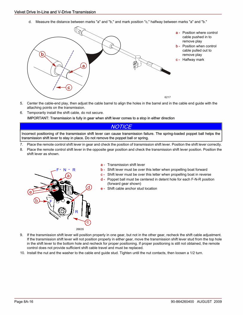
d. Measure the distance between marks "a" and "b," and mark position "c," halfway between marks "a" and "b."
a - Position where controlcable pushed in toremove play
b - Position when controlcable pulled out toremove play
c - Halfway mark
5. Center the cable‑end play, then adjust the cable barrel to align the holes in the barrel and in the cable end guide with theattaching points on the transmission.
6. Temporarily install the shift cable, do not secure.IMPORTANT: Transmission is fully in gear when shift lever comes to a stop in either direction
NOTICEIncorrect positioning of the transmission shift lever can cause transmission failure. The spring‑loaded poppet ball helps thetransmission shift lever to stay in place. Do not remove the poppet ball or spring.
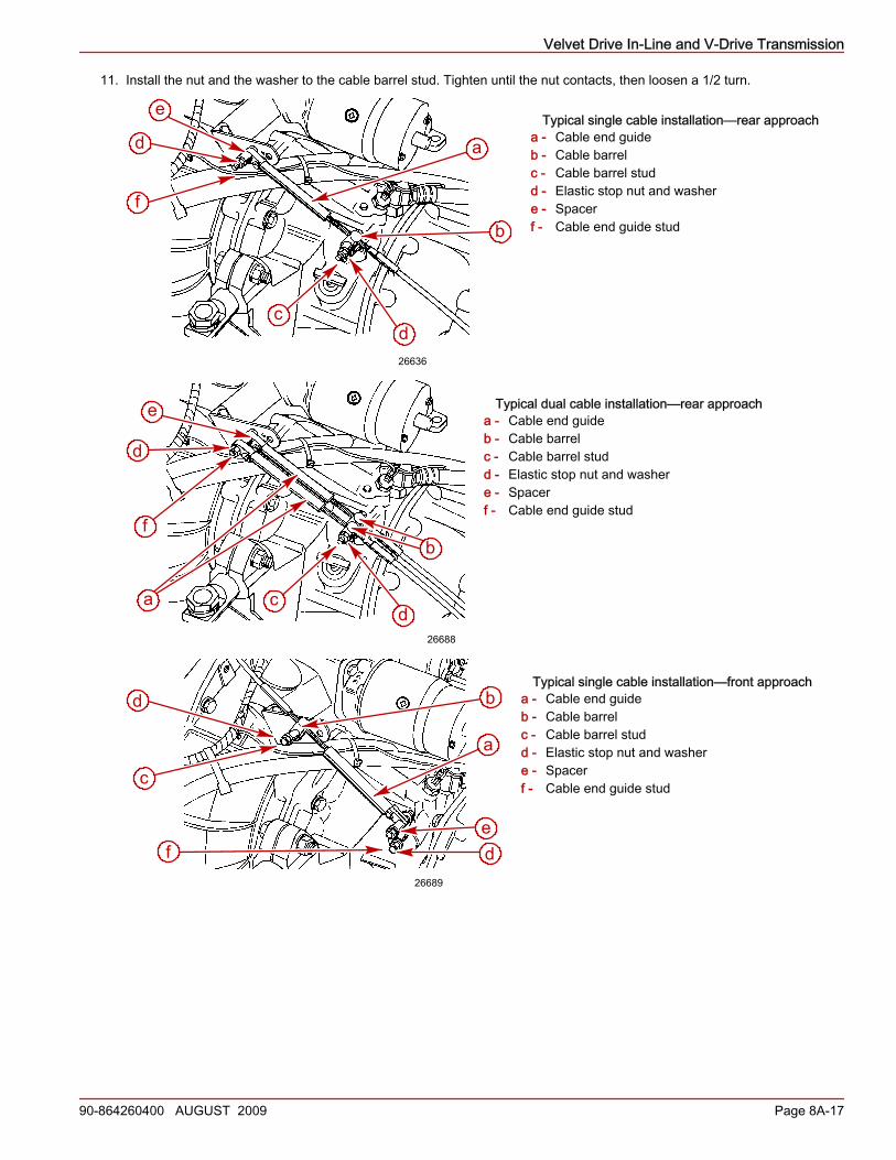
7. Place the remote control shift lever in gear and check the position of transmission shift lever. Position the shift lever correctly.8. Place the remote control shift lever in the opposite gear position and check the transmission shift lever position. Position the
shift lever as shown.
a - Transmission shift leverb - Shift lever must be over this letter when propelling boat forwardc - Shift lever must be over this letter when propelling boat in reversed - Poppet ball must be centered in detent hole for each F‑N‑R position
(forward gear shown)e - Shift cable anchor stud location
9. If the transmission shift lever will position properly in one gear, but not in the other gear, recheck the shift cable adjustment.If the transmission shift lever will not position properly in either gear, move the transmission shift lever stud from the top holein the shift lever to the bottom hole and recheck for proper positioning. If proper positioning is still not obtained, the remotecontrol does not provide sufficient shift cable travel and must be replaced.
10. Install the nut and the washer to the cable end guide stud. Tighten until the nut contacts, then loosen a 1/2 turn.
6217
b
a
c
F - N - R
F
R
a
b
c
de
26635
Velvet Drive In-Line and V-Drive Transmission
90-864260400 AUGUST 2009 Page 8A-17
11. Install the nut and the washer to the cable barrel stud. Tighten until the nut contacts, then loosen a 1/2 turn.
Typical single cable installation—rear approacha - Cable end guideb - Cable barrelc - Cable barrel studd - Elastic stop nut and washere - Spacerf - Cable end guide stud
Typical dual cable installation—rear approacha - Cable end guideb - Cable barrelc - Cable barrel studd - Elastic stop nut and washere - Spacerf - Cable end guide stud
Typical single cable installation—front approacha - Cable end guideb - Cable barrelc - Cable barrel studd - Elastic stop nut and washere - Spacerf - Cable end guide stud
a
b
cd
f
e
d
26636
a
b
cd
e
f
d
26688
a
b
c
d
ef d
26689
Velvet Drive In-Line and V-Drive Transmission
Page 8A-18 90-864260400 AUGUST 2009
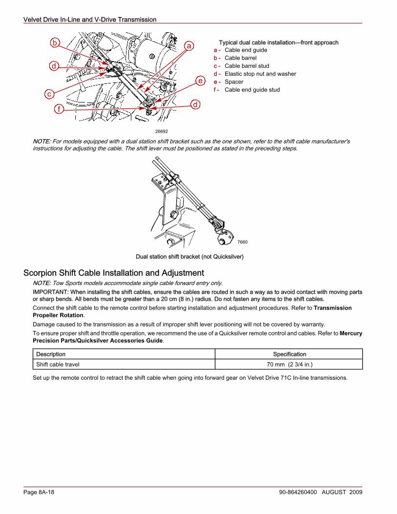
Typical dual cable installation—front approacha - Cable end guideb - Cable barrelc - Cable barrel studd - Elastic stop nut and washere - Spacerf - Cable end guide stud
NOTE: For models equipped with a dual station shift bracket such as the one shown, refer to the shift cable manufacturer'sinstructions for adjusting the cable. The shift lever must be positioned as stated in the preceding steps.
7660
Dual station shift bracket (not Quicksilver)
Scorpion Shift Cable Installation and AdjustmentNOTE: Tow Sports models accommodate single cable forward entry only.IMPORTANT: When installing the shift cables, ensure the cables are routed in such a way as to avoid contact with moving partsor sharp bends. All bends must be greater than a 20 cm (8 in.) radius. Do not fasten any items to the shift cables.Connect the shift cable to the remote control before starting installation and adjustment procedures. Refer to TransmissionPropeller Rotation.Damage caused to the transmission as a result of improper shift lever positioning will not be covered by warranty.To ensure proper shift and throttle operation, we recommend the use of a Quicksilver remote control and cables. Refer to MercuryPrecision Parts/Quicksilver Accessories Guide.
Description SpecificationShift cable travel 70 mm (2 3/4 in.)
Set up the remote control to retract the shift cable when going into forward gear on Velvet Drive 71C In‑line transmissions.
ab
c
d
f
e
d
26692
Velvet Drive In-Line and V-Drive Transmission
90-864260400 AUGUST 2009 Page 8A-19
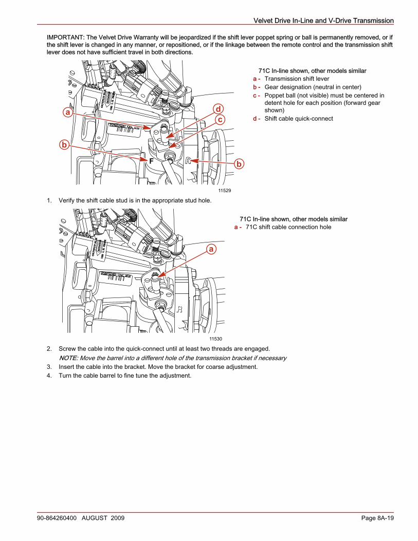
IMPORTANT: The Velvet Drive Warranty will be jeopardized if the shift lever poppet spring or ball is permanently removed, or ifthe shift lever is changed in any manner, or repositioned, or if the linkage between the remote control and the transmission shiftlever does not have sufficient travel in both directions.
71C In-line shown, other models similara - Transmission shift leverb - Gear designation (neutral in center)c - Poppet ball (not visible) must be centered in
detent hole for each position (forward gearshown)
d - Shift cable quick‑connect
1. Verify the shift cable stud is in the appropriate stud hole.
71C In-line shown, other models similara - 71C shift cable connection hole
2. Screw the cable into the quick‑connect until at least two threads are engaged.NOTE: Move the barrel into a different hole of the transmission bracket if necessary
3. Insert the cable into the bracket. Move the bracket for coarse adjustment.4. Turn the cable barrel to fine tune the adjustment.
OU
TP
UT
FL
AR
OTA
TIO
NU
SE
L. H
. PR
OPE
F
11529
da
b
c
b
OU
TP
UT
FL
AR
OTA
TIO
NU
SE
L. H
. PR
OPE
a
11530
Velvet Drive In-Line and V-Drive Transmission
Page 8A-20 90-864260400 AUGUST 2009
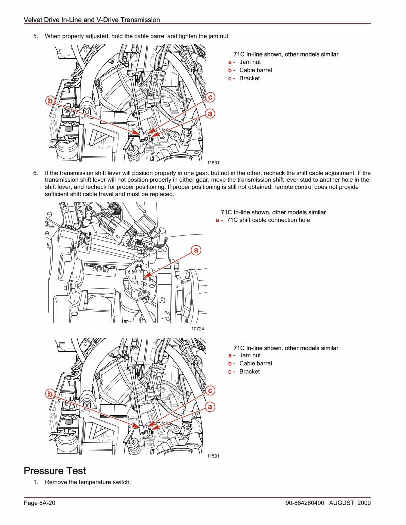
5. When properly adjusted, hold the cable barrel and tighten the jam nut.
71C In-line shown, other models similara - Jam nutb - Cable barrelc - Bracket
6. If the transmission shift lever will position properly in one gear, but not in the other, recheck the shift cable adjustment. If thetransmission shift lever will not position properly in either gear, move the transmission shift lever stud to another hole in theshift lever, and recheck for proper positioning. If proper positioning is still not obtained, remote control does not providesufficient shift cable travel and must be replaced.
71C In-line shown, other models similara - 71C shift cable connection hole
71C In-line shown, other models similara - Jam nutb - Cable barrelc - Bracket
Pressure Test1. Remove the temperature switch.
a
cb
11531
OU
TP
UT
FL
AR
OTA
TIO
NU
SE
L. H
. PR
OPE
a
10724
a
cb
11531
Velvet Drive In-Line and V-Drive Transmission
90-864260400 AUGUST 2009 Page 8A-21
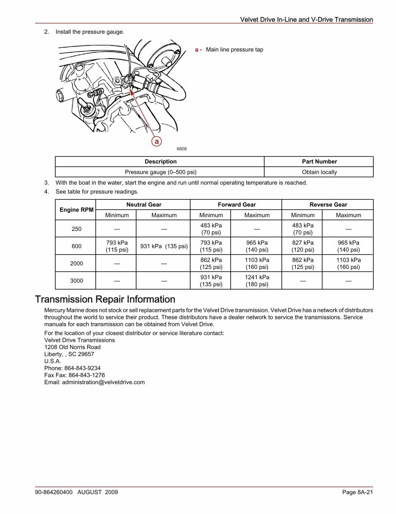
2. Install the pressure gauge.
a - Main line pressure tap
Description Part Number
Pressure gauge (0–500 psi) Obtain locally
3. With the boat in the water, start the engine and run until normal operating temperature is reached.4. See table for pressure readings.
Engine RPMNeutral Gear Forward Gear Reverse Gear
Minimum Maximum Minimum Maximum Minimum Maximum
250 — — 483 kPa(70 psi) — 483 kPa
(70 psi) —
600 793 kPa(115 psi) 931 kPa (135 psi) 793 kPa
(115 psi)965 kPa(140 psi)
827 kPa(120 psi)
965 kPa(140 psi)
2000 — — 862 kPa(125 psi)
1103 kPa(160 psi)
862 kPa(125 psi)
1103 kPa(160 psi)
3000 — — 931 kPa(135 psi)
1241 kPa(180 psi) — —
Transmission Repair InformationMercury Marine does not stock or sell replacement parts for the Velvet Drive transmission. Velvet Drive has a network of distributorsthroughout the world to service their product. These distributors have a dealer network to service the transmissions. Servicemanuals for each transmission can be obtained from Velvet Drive.For the location of your closest distributor or service literature contact:Velvet Drive Transmissions1208 Old Norris RoadLiberty, , SC 29657U.S.A.Phone: 864-843-9234Fax Fax: 864-843-1276Email: [email protected]
a6806

Velvet Drive In-Line and V-Drive Transmission
Notes:
Page 8A-22 90-864260400 AUGUST 2009