Embed Size (px)
Citation preview

Everything’s possible.
www.a-m-c.com
Setup SoftwareOperator’s Manual
DriveWare® 7User Guide
MNDGDWUG-05

Preface
ADVANCED Motion Controls constantly strives to improve all of its products. We review the information in this document regularly and we welcome any suggestions for improvement. We reserve the right to modify equipment and documentation without prior notice.
For the latest revision of this manual, visit the company’s website at www.a-m-c.com. Otherwise, contact the company directly at:
ADVANCED Motion Controls • 3805 Calle Tecate Camarillo, CA • 93012-5068 USA
This manual is for the exclusive use of ADVANCED Motion Controls. The reproduction, transmission or use of this document or its contents is prohibited without the expressed written permission of ADVANCED Motion Controls.
General Safety
You must install and operate ADVANCED Motion Controls motion control equipment so that you meet all applicable safety requirements. Ensure that you identify the relevant standards and comply with them. Failure to do so may result in damage to equipment and personal injury.
Read this entire manual prior to attempting to install or operate the drive. Become familiar with practices and procedures that allow you to operate these drives safely and effectively. You are responsible for determining the suitability of this product for the intended application. ADVANCED Motion Controls is neither responsible nor liable for indirect or consequential damages resulting from the inappropriate use of this product.
High-performance motion control equipment can move rapidly with very high forces. Unexpected motion may occur especially during product commissioning. Keep clear of any operational machinery and never touch them while they are working.
MNDGDWUG-05 ii

/
Keep clear of enclosed units, motor terminals, and transformer terminals when power is applied to the equipment. Follow these safety guidelines:
• Always turn off the main power and allow sufficient time for complete discharge before making any connections to the drive.
• Make sure that the minimum inductance requirements are met. Pulse Width Modulated (PWM) amplifiers deliver a pulsed output that requires a minimum amount of load inductance for proper operation.
• Do not rotate the motor shaft without power. The motor acts as a generator and will charge up the power supply capacitors through the amplifier. Excessive speeds may cause over-voltage breakdown in the power output stage. Note that an amplifier having an internal power converter that operates from the high voltage supply will become operative.
• Do not short the motor leads at high motor speeds. When the motor is shorted, its own generated voltage may produce a current flow as high as 10 times the amplifier current. The short itself may not damage the amplifier but may damage the motor.
• Do not make any connections to any internal circuitry. Only connections to designated connectors are allowed.
ADVANCED Motion Controls, the combined isosceles trapezoid/right triangle logo, and DriveWare® are either registered trademarks or trademarks of ADVANCED Motion Controls in the United States and/or other countries. All other trademarks are the property of their respective owners.
© 2012 ADVANCED Motion Controls. All rights reserved.
Document ID Revision Date Changes
MNDGDWUG-03 5.4 7/8/2008 Manual Format Update
MNDGDWUG-04 5.8.5 1/9/2009
- Updated Command Source window information- Added DriveLibrary section
- Updated Commutation window information
- Added Status Bar section- Updated Help menu drive information window Software Version and Display the Drive Information
- Changed Working with the Stoplight section to Working with the Command Toolbar, and updated Stoplight button references throughout to Enable/Disable and Stop buttons
- Updated the Digital Oscilloscope section
- Updated the Tuning and Commutation procedure
MNDGDWUG-05 7.0 7/2012
- Added Ethernet and USB as connection options when Connecting to the Drive- Added Troubleshooting information
- Added Control Loop Architecture information
- Changed Positive Target Velocity and Negative Target Velocity event designations to Positive Velocity Limit and Negative Velocity Limit, respectively
- Added Current Limiting Algorithm information- Updated Current Limits information
- Updated Digital Inputs information
- Added Capture Configuration Window information- Updated Digital Outputs information
- Added Network Settings information
- Added PDO Configuration information- Updated for new interface structure
iii MNDGDWUG-05

Contents
1 Introduction 1
1.1 Getting Started . . . . . . . . . . . . . . . . . . . . . . . . . . . . . . . . . . . . . . . . . 21.1.1 Software Files . . . . . . . . . . . . . . . . . . . . . . . . . . . . . . . . . . . . . 21.1.2 Workspace Display . . . . . . . . . . . . . . . . . . . . . . . . . . . . . . . . 2
Menu Bar and Associated Toolbar Icons . . . . . . . . . . . . . . . 3Setup Panel . . . . . . . . . . . . . . . . . . . . . . . . . . . . . . . . . . . . . . . 5Status Panel . . . . . . . . . . . . . . . . . . . . . . . . . . . . . . . . . . . . . . . 5Dynamic Help Browser . . . . . . . . . . . . . . . . . . . . . . . . . . . . . . 5Status Bar . . . . . . . . . . . . . . . . . . . . . . . . . . . . . . . . . . . . . . . . . 5Caption Bar . . . . . . . . . . . . . . . . . . . . . . . . . . . . . . . . . . . . . . . 6
1.2 Using the Setup Software . . . . . . . . . . . . . . . . . . . . . . . . . . . . . . . . . 71.2.1 Opening a File . . . . . . . . . . . . . . . . . . . . . . . . . . . . . . . . . . . . 71.2.2 Working with the Drive . . . . . . . . . . . . . . . . . . . . . . . . . . . . . 7
Naming the Drive . . . . . . . . . . . . . . . . . . . . . . . . . . . . . . . . . . 7Connecting to the Drive . . . . . . . . . . . . . . . . . . . . . . . . . . . . 7Disconnecting from the drive . . . . . . . . . . . . . . . . . . . . . . . . 8
1.2.3 Hot Key . . . . . . . . . . . . . . . . . . . . . . . . . . . . . . . . . . . . . . . . . . 81.2.4 Working with the Command Toolbar . . . . . . . . . . . . . . . . . 91.2.5 Working with the Setup Software Windows . . . . . . . . . . . 10
Showing/hiding the Toolbars and Caption Bar . . . . . . . . . 10Showing/hiding Panels . . . . . . . . . . . . . . . . . . . . . . . . . . . . . 10Arranging the Windows . . . . . . . . . . . . . . . . . . . . . . . . . . . . 10
1.3 Getting Help . . . . . . . . . . . . . . . . . . . . . . . . . . . . . . . . . . . . . . . . . . 111.3.1 Dynamic Help . . . . . . . . . . . . . . . . . . . . . . . . . . . . . . . . . . . 111.3.2 Technical Support . . . . . . . . . . . . . . . . . . . . . . . . . . . . . . . . 11
Software Version . . . . . . . . . . . . . . . . . . . . . . . . . . . . . . . . . . 11Display the Drive Information . . . . . . . . . . . . . . . . . . . . . . . 11
1.4 Saving Your Setup . . . . . . . . . . . . . . . . . . . . . . . . . . . . . . . . . . . . . . 111.4.1 Storing the Changes onto the Drive . . . . . . . . . . . . . . . . . 11
MNDGDWUG-05 iv
/
1.4.2 Saving the Project File onto Your Computer . . . . . . . . . . 121.5 Exiting the Program . . . . . . . . . . . . . . . . . . . . . . . . . . . . . . . . . . . . 12
2 Connecting to the Drive 13
2.1 Connecting to the Drive . . . . . . . . . . . . . . . . . . . . . . . . . . . . . . . . 142.2 Changing Communication Parameters . . . . . . . . . . . . . . . . . . . 15
3 Configuring the Drive 16
3.1 Configuration . . . . . . . . . . . . . . . . . . . . . . . . . . . . . . . . . . . . . . . . . 173.1.1 Command Source . . . . . . . . . . . . . . . . . . . . . . . . . . . . . . . . 173.1.2 Command Limiter . . . . . . . . . . . . . . . . . . . . . . . . . . . . . . . . 20
3.2 Loop Feedback . . . . . . . . . . . . . . . . . . . . . . . . . . . . . . . . . . . . . . . 213.2.1 Velocity Feedback Source . . . . . . . . . . . . . . . . . . . . . . . . . 213.2.2 Position Feedback Source . . . . . . . . . . . . . . . . . . . . . . . . . 21
3.3 Power-up Settings . . . . . . . . . . . . . . . . . . . . . . . . . . . . . . . . . . . . . . 223.4 Motor Parameters . . . . . . . . . . . . . . . . . . . . . . . . . . . . . . . . . . . . . . 23
3.4.1 Motor Selection . . . . . . . . . . . . . . . . . . . . . . . . . . . . . . . . . . 233.4.2 Motor Parameters . . . . . . . . . . . . . . . . . . . . . . . . . . . . . . . . 233.4.3 Feedback Type . . . . . . . . . . . . . . . . . . . . . . . . . . . . . . . . . . 253.4.4 Commutation . . . . . . . . . . . . . . . . . . . . . . . . . . . . . . . . . . . . 263.4.5 Braking . . . . . . . . . . . . . . . . . . . . . . . . . . . . . . . . . . . . . . . . . 27
3.5 AutoCommutation . . . . . . . . . . . . . . . . . . . . . . . . . . . . . . . . . . . . . 283.6 Auxiliary Encoder Input . . . . . . . . . . . . . . . . . . . . . . . . . . . . . . . . . 29
3.6.1 Feedback Parameters . . . . . . . . . . . . . . . . . . . . . . . . . . . . 293.7 Encoder Output . . . . . . . . . . . . . . . . . . . . . . . . . . . . . . . . . . . . . . . 303.8 Inputs / Outputs . . . . . . . . . . . . . . . . . . . . . . . . . . . . . . . . . . . . . . . 31
3.8.1 Analog Inputs . . . . . . . . . . . . . . . . . . . . . . . . . . . . . . . . . . . . 313.8.2 Analog Outputs . . . . . . . . . . . . . . . . . . . . . . . . . . . . . . . . . . 323.8.3 Digital Inputs . . . . . . . . . . . . . . . . . . . . . . . . . . . . . . . . . . . . . 323.8.4 Digital Outputs . . . . . . . . . . . . . . . . . . . . . . . . . . . . . . . . . . . 33
3.9 Limits . . . . . . . . . . . . . . . . . . . . . . . . . . . . . . . . . . . . . . . . . . . . . . . . . 343.9.1 Current Limits . . . . . . . . . . . . . . . . . . . . . . . . . . . . . . . . . . . . 343.9.2 Velocity Limits . . . . . . . . . . . . . . . . . . . . . . . . . . . . . . . . . . . . 353.9.3 Position Limits . . . . . . . . . . . . . . . . . . . . . . . . . . . . . . . . . . . . 353.9.4 Stop . . . . . . . . . . . . . . . . . . . . . . . . . . . . . . . . . . . . . . . . . . . . 35
MNDGDWUG-05 v

/
3.9.5 Voltage Limits . . . . . . . . . . . . . . . . . . . . . . . . . . . . . . . . . . . . 363.9.6 Temperature Limits . . . . . . . . . . . . . . . . . . . . . . . . . . . . . . . 38
3.10 Events . . . . . . . . . . . . . . . . . . . . . . . . . . . . . . . . . . . . . . . . . . . . . . . 393.10.1 Basic Events . . . . . . . . . . . . . . . . . . . . . . . . . . . . . . . . . . . . 403.10.2 Advanced Events . . . . . . . . . . . . . . . . . . . . . . . . . . . . . . . 40
3.11 Network Settings . . . . . . . . . . . . . . . . . . . . . . . . . . . . . . . . . . . . . . 41Drive Operation Mode . . . . . . . . . . . . . . . . . . . . . . . . . . . . . 41
3.12 PDO Configuration . . . . . . . . . . . . . . . . . . . . . . . . . . . . . . . . . . . . 423.12.1 RPDOs - CAN Drive . . . . . . . . . . . . . . . . . . . . . . . . . . . . . . 423.12.2 TPDOs - CAN Drive . . . . . . . . . . . . . . . . . . . . . . . . . . . . . . . 423.12.3 TPDO Events - CAN Drive . . . . . . . . . . . . . . . . . . . . . . . . . 433.12.4 RPDOs and TPDOs - Ethernet Powerlink or EtherCAT . . . 43
3.13 Tuning . . . . . . . . . . . . . . . . . . . . . . . . . . . . . . . . . . . . . . . . . . . . . . . 443.13.1 Current Loop Gains . . . . . . . . . . . . . . . . . . . . . . . . . . . . . . 443.13.2 Gain Sets . . . . . . . . . . . . . . . . . . . . . . . . . . . . . . . . . . . . . . . 44
Set Position . . . . . . . . . . . . . . . . . . . . . . . . . . . . . . . . . . . . . . 453.13.3 Advanced Settings . . . . . . . . . . . . . . . . . . . . . . . . . . . . . . 453.13.4 Filters . . . . . . . . . . . . . . . . . . . . . . . . . . . . . . . . . . . . . . . . . . 45
4 Tuning and Commutation 46
4.1 Current Loop Tuning . . . . . . . . . . . . . . . . . . . . . . . . . . . . . . . . . . . . 48Step 1: Inputs/Outputs Configuration setup . . . . . . . . . . . 48Step 2: Waveform Generator Setup . . . . . . . . . . . . . . . . . . 48Step 3: Oscilloscope setup . . . . . . . . . . . . . . . . . . . . . . . . . 48Step 4: Tuning . . . . . . . . . . . . . . . . . . . . . . . . . . . . . . . . . . . . 49
4.2 Commutation . . . . . . . . . . . . . . . . . . . . . . . . . . . . . . . . . . . . . . . . . 504.2.1 AutoCommutation™ . . . . . . . . . . . . . . . . . . . . . . . . . . . . . 50
AutoCommutation™ Warnings . . . . . . . . . . . . . . . . . . . . . 514.2.2 Manual Commutation Procedure . . . . . . . . . . . . . . . . . . . 52
Setting over speed limits . . . . . . . . . . . . . . . . . . . . . . . . . . . 53Performing manual commutation . . . . . . . . . . . . . . . . . . . 53
4.2.3 Phase Detect . . . . . . . . . . . . . . . . . . . . . . . . . . . . . . . . . . . . 554.3 Velocity Loop Tuning . . . . . . . . . . . . . . . . . . . . . . . . . . . . . . . . . . . 56
Step 1: Waveform Generator setup . . . . . . . . . . . . . . . . . . 56Step 2: Oscilloscope setup . . . . . . . . . . . . . . . . . . . . . . . . . 56Step 3: Tuning . . . . . . . . . . . . . . . . . . . . . . . . . . . . . . . . . . . . 56
4.4 Position Loop Tuning . . . . . . . . . . . . . . . . . . . . . . . . . . . . . . . . . . . . 58Step 1: Waveform Generator setup . . . . . . . . . . . . . . . . . . 58
MNDGDWUG-05 vi

/
Step 2: Oscilloscope setup . . . . . . . . . . . . . . . . . . . . . . . . . 58Step 3: Tuning . . . . . . . . . . . . . . . . . . . . . . . . . . . . . . . . . . . . 59
5 Motion Tasks 60
5.1 Motion Tasks . . . . . . . . . . . . . . . . . . . . . . . . . . . . . . . . . . . . . . . . . . 615.1.1 Homing . . . . . . . . . . . . . . . . . . . . . . . . . . . . . . . . . . . . . . . . . 615.1.2 Indexes . . . . . . . . . . . . . . . . . . . . . . . . . . . . . . . . . . . . . . . . . 63
Executing an Index Task . . . . . . . . . . . . . . . . . . . . . . . . . . . 63Dynamic Indexes . . . . . . . . . . . . . . . . . . . . . . . . . . . . . . . . . 64
5.1.3 PVT . . . . . . . . . . . . . . . . . . . . . . . . . . . . . . . . . . . . . . . . . . . . . 65How To Construct A PVT Points File . . . . . . . . . . . . . . . . . . . 65
5.1.4 Jogs . . . . . . . . . . . . . . . . . . . . . . . . . . . . . . . . . . . . . . . . . . . . 67Executing a Jog Task . . . . . . . . . . . . . . . . . . . . . . . . . . . . . . 67
6 Downloading the Firmware 68
6.1 Prepare for Download . . . . . . . . . . . . . . . . . . . . . . . . . . . . . . . . . . 686.2 Open the Firmware Download Window . . . . . . . . . . . . . . . . . . . 686.3 Downloading the Firmware . . . . . . . . . . . . . . . . . . . . . . . . . . . . . . 69
A Tools and Functions 70
A.1 Digital Oscilloscope . . . . . . . . . . . . . . . . . . . . . . . . . . . . . . . . . . . . 70Channel Select . . . . . . . . . . . . . . . . . . . . . . . . . . . . . . . . . . . 70Presets . . . . . . . . . . . . . . . . . . . . . . . . . . . . . . . . . . . . . . . . . . 71Display . . . . . . . . . . . . . . . . . . . . . . . . . . . . . . . . . . . . . . . . . . 71Trigger . . . . . . . . . . . . . . . . . . . . . . . . . . . . . . . . . . . . . . . . . . 71Measure . . . . . . . . . . . . . . . . . . . . . . . . . . . . . . . . . . . . . . . . . 71
A.1.1 Waveform Generator . . . . . . . . . . . . . . . . . . . . . . . . . . . . . 72A.2 Multimeter . . . . . . . . . . . . . . . . . . . . . . . . . . . . . . . . . . . . . . . . . . . . 73A.3 User Units . . . . . . . . . . . . . . . . . . . . . . . . . . . . . . . . . . . . . . . . . . . . . 74A.4 Motion Panel . . . . . . . . . . . . . . . . . . . . . . . . . . . . . . . . . . . . . . . . . 75
Indexes . . . . . . . . . . . . . . . . . . . . . . . . . . . . . . . . . . . . . . . . . . 75Dynamic Index . . . . . . . . . . . . . . . . . . . . . . . . . . . . . . . . . . . 75Jog . . . . . . . . . . . . . . . . . . . . . . . . . . . . . . . . . . . . . . . . . . . . . 75
MNDGDWUG-05 vii

/
PVT . . . . . . . . . . . . . . . . . . . . . . . . . . . . . . . . . . . . . . . . . . . . . 75Motion Status . . . . . . . . . . . . . . . . . . . . . . . . . . . . . . . . . . . . 76
A.5 Signal Definitions . . . . . . . . . . . . . . . . . . . . . . . . . . . . . . . . . . . . . . 77Current measurements . . . . . . . . . . . . . . . . . . . . . . . . . . . . 77Velocity measurements . . . . . . . . . . . . . . . . . . . . . . . . . . . . 77Position measurements . . . . . . . . . . . . . . . . . . . . . . . . . . . . 78Commutation . . . . . . . . . . . . . . . . . . . . . . . . . . . . . . . . . . . . 78Voltage . . . . . . . . . . . . . . . . . . . . . . . . . . . . . . . . . . . . . . . . . 78Command Limiter . . . . . . . . . . . . . . . . . . . . . . . . . . . . . . . . . 78Temperature . . . . . . . . . . . . . . . . . . . . . . . . . . . . . . . . . . . . . 79Torque . . . . . . . . . . . . . . . . . . . . . . . . . . . . . . . . . . . . . . . . . . 79Drive . . . . . . . . . . . . . . . . . . . . . . . . . . . . . . . . . . . . . . . . . . . . 79Commanded Input value . . . . . . . . . . . . . . . . . . . . . . . . . . 79Deadband Input . . . . . . . . . . . . . . . . . . . . . . . . . . . . . . . . . 79PWM Input . . . . . . . . . . . . . . . . . . . . . . . . . . . . . . . . . . . . . . . 79
A.6 Drive Status . . . . . . . . . . . . . . . . . . . . . . . . . . . . . . . . . . . . . . . . . . . 80A.7 Critical Event Activity . . . . . . . . . . . . . . . . . . . . . . . . . . . . . . . . . . . 81A.8 Event Counters . . . . . . . . . . . . . . . . . . . . . . . . . . . . . . . . . . . . . . . . 81
B Current Limiting 82
B.1 Understanding the Limit Envelope . . . . . . . . . . . . . . . . . . . . . . . . 82B.2 Current Limiting Algorithm . . . . . . . . . . . . . . . . . . . . . . . . . . . . . . . 86
B.2.1 Time-Based Peak Current Limiting . . . . . . . . . . . . . . . . . . . 87B.2.2 Time-Based Non-Peak Current Limiting . . . . . . . . . . . . . . . 88B.2.3 Time-Based Current Recovery . . . . . . . . . . . . . . . . . . . . . . 89B.2.4 Charge-Based Peak Current Limiting . . . . . . . . . . . . . . . . 90B.2.5 Charge-Based Non-Peak Current Limiting . . . . . . . . . . . . 91B.2.6 Charge-Based Current Recovery . . . . . . . . . . . . . . . . . . . 92B.2.7 RMS Current Scaling . . . . . . . . . . . . . . . . . . . . . . . . . . . . . . 93
B.3 Calculating Current Limits . . . . . . . . . . . . . . . . . . . . . . . . . . . . . . . 94B.3.1 Example 1: Foldback Current . . . . . . . . . . . . . . . . . . . . . . 95B.3.2 Example 2: Peak Current Recovery . . . . . . . . . . . . . . . . . 96
MNDGDWUG-05 viii

/
C Control Loop Architecture 97
D Filtering Velocity Feedback 98
D.1 Effects of the Feedback Filter . . . . . . . . . . . . . . . . . . . . . . . . . . . . 99D.1.1 Cutoff Frequency Set to Infinite . . . . . . . . . . . . . . . . . . . . 99D.1.2 Cutoff Frequency Set to 300Hz . . . . . . . . . . . . . . . . . . . . . 99D.1.3 Cutoff Frequency Set to 50Hz . . . . . . . . . . . . . . . . . . . . . 100D.1.4 Cutoff Frequency Set to 10Hz . . . . . . . . . . . . . . . . . . . . . 100
D.2 Conclusion . . . . . . . . . . . . . . . . . . . . . . . . . . . . . . . . . . . . . . . . . . 100
E Troubleshooting 101
E.1 Setup Software Safety Actions . . . . . . . . . . . . . . . . . . . . . . . . . . 101E.2 Potential External System Errors . . . . . . . . . . . . . . . . . . . . . . . . . . 101E.3 Events and I/O Descriptions and Troubleshooting Methods . . 102
MNDGDWUG-05 ix

1 Introduction
This document provides instructions on how to use the setup software to connect to, set up and control digital servo drives.These instructions walk you through the commissioning steps necessary to set drive limits, tune the current, velocity, and position control loops, and assign automated functions to drive events.The following major sections are covered:• “Connecting to the Drive” on page 13• “Configuring the Drive” on page 16• “Tuning and Commutation” on page 46
Follow the procedures in this chapter to get an overview of many functions. Familiarize yourself with the files on your computer, the software workspace and controls of the software. Later chapters provide more details in using these functions.Before proceeding, you must accomplish the following actions: Read the release notes and installation text files for your setup software version. Install the setup software.
MNDGDWUG-05 1
Introduction / Getting Started
1.1 Getting StartedAfter installing the setup software on your computer, you can run the application from your Start > Programs menu or desktop icon.When you first start the setup software, you see the following choices:• Open - This will allow you to browse through the files on your computer to select a previously saved project file to open, without having to connect to a drive. The project can then be configured or modified before downloading the project file into a drive.• Connect - This will allow you to immediately connect to a drive. The drive can then be set up and configured for operation, and the information saved as a project file.
1.1.1 Software FilesLook in the folder in which you placed the application; by default, this location is under C:\Program Files. This folder includes the subdirectories:• MotorDB holding a library of *.dbs database files making up the motor database.• My Firmware Files holding a library of *.aff firmware files for various drives.• My Projects holding a library of *.adf project files, each with the parameters and controls specific to a particular drive-and-motor setup.
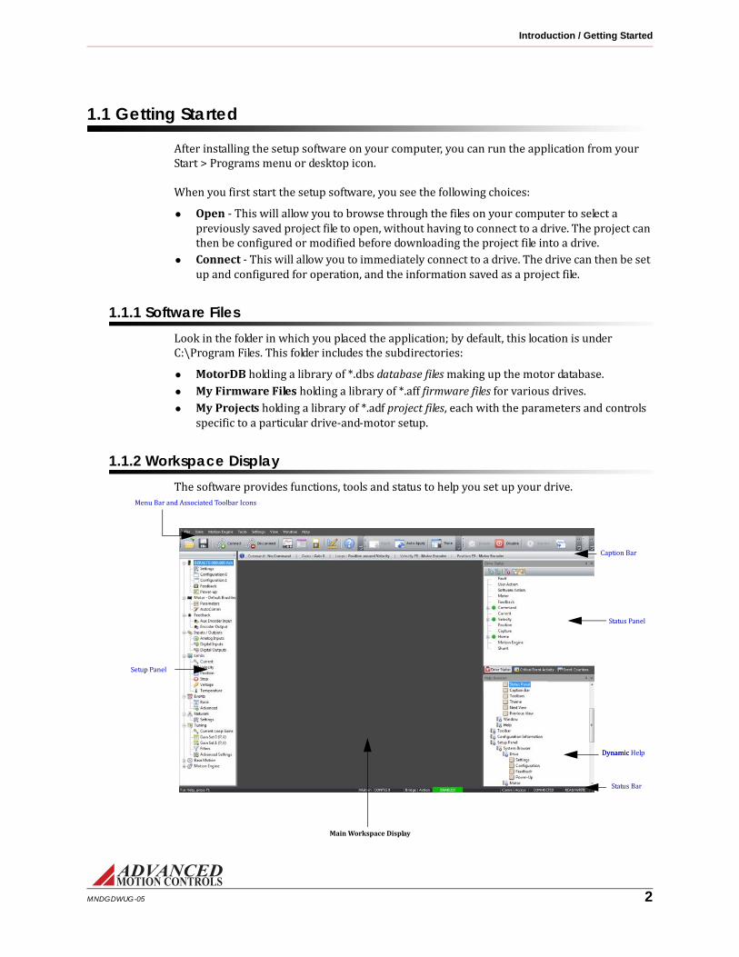
1.1.2 Workspace DisplayThe software provides functions, tools and status to help you set up your drive.Caption Bar
Status Panel
Status Bar
Setup Panel
Menu Bar and Associated Toolbar Icons
Main Workspace Display
Dynamic Help Dynamic
MNDGDWUG-05 2

Introduction / Getting Started
Menu Bar and Associated Toolbar Icons At the top of the screen are pull down menus and a toolbar for access to many tools and functions.
MNDGDWUG-05 3

Introduction / Getting Started
Function Menu Pull-down Toolbar Keys
Open a project file File > Open Project Crtl+O
Save a project file to PC Save Project Crtl+S
Save a project file to PC as a file name Save Project As... - - - - - -
Apply changes made to active window Apply Changes Ctrl+L
Automatically apply changes made Auto Apply Ctrl+U
Close the program Exit - - - Alt+F4
Power up or down the bridge Drive > Enable
Disable
Alt+E
Alt+D
Allow motion to occur or disallow motion by sending a Commanded Quick Stop
Motion Ready
Stop Motion
Alt+G
Alt+P
Change the active Configuration Switch Configurations Alt+C
Change the active Gain Set Switch Gains Alt+A
Connect to the drive or change connection settings once connected
Connect Ctrl+N
Disconnect from the drive Disconnect Ctrl+D
Store project on the drive Store to drive Alt+O
Upload settings from drive Restore from drive - - - - - -
Update drive firmware Firmware Download - - - - - -
Display drive information About Drive - - - - - -
Turn the Motion Engine on or off Motion Engine > On Alt+R
Reset the Motion Engine Reset Ctrl+R
Open the Scope/Tuning tool Tools > Scope/Tuning Ctrl+E
Open the Multimeter tool Multimeter Ctrl+M
Brings up the Motion Panel window. Motion Panel Ctrl+T
Brings up the Waveform Generator window.
Waveform Generator - - - - - -
Assign the Disable Drive Hotkey Settings > Hot Key Settings - - - - - -
Open the User Units window User Units Ctrl+R
MNDGDWUG-05 4

Introduction / Getting Started
Setup Panel Navigate between the setup windows to configure the drive. Each panel contains multiple headings for specific drive parameters. Select a configuration item from the Setup Panel to open a window in the main workspace display.Status Panel The Status Panel provides real-time information on drive events and actions.
• Drive Status - Shows drive events (current and history) and is a useful troubleshooting tool.• Critical Event Activity - Lists drive faults and fault events along with the time they occurred.• Event Counters - Lists the number of times faults have occurred since the drive has been in operation.
Dynamic Help Browser Dynamic Help tracks user movements through the software workspace and automatically navigates to the appropriate Help topic in the list. Select a topic from the Dynamic Help Panel to open a new tab with the Help information.Status Bar The Status Bar provides information on the drive configuration, bridge state, connection status, and accessibility. From left to right across the bottom of the workspace window, the Status Bar provides information on:
• Motion - Displays motion tasks the drive is currently performing when the motion engine is enabled. Will be blank if no task is currently active.— Config 0: Configuration 0 is currently selected, and no autonomous modes are active.— Config 1: Configuration 1 is currently selected, and no autonomous modes are active.— Ready: Motion Engine is on and the drive is ready to receive commands from the Motion Engine. No motion tasks are currently active.— Home: Drive is actively in homing mode.— Jog: Drive is actively in jog mode.— Index (# or name): Drive is running an index.— Waveform: The Waveform Generator is controlling the axis.— AutoComm: The AutoCommutation process is controlling the axis.
Show or hide the Setup Panel View > Setup Panel - - - - - -
Show or hide the Status Panel Status Panel - - - - - -
Show or hide the Caption Bar Caption Bar - - - - - -
Customize the Toolbar icons Toolbar - - - - - -
Customize the display themes Theme - - - - - -
Arrange software windows into horizontal tabbed group
Window > New Horizontal Tab Group - - - - - -
Arrange software windows into vertical tabbed group
New Vertical Tab Group - - - - - -
Closes all open tabs Close All Tabs - - - - - -
Re-arranges all toolbars and panels to their default locations
Reset Window Layout - - - - - -
Open the software Help file, or display the Dynamic Help Browser
Help > Help... F1
Display software information, version number, and copyright.
About... - - - - - -
Function Menu Pull-down Toolbar Keys
MNDGDWUG-05 5

Introduction / Getting Started
• Bridge - Shows the status of the drive.— Enabled: Drive is enabled (note that a Stop condition is considered enabled).— Disabled: Drive is disabled (note that a Dynamic Brake condition is considered disabled).
• Action - Shows the present bridge action as the result of a drive or system event. Hovering the mouse pointer over the Action status will display the event causing the action.— Bridge Disabled: The bridge is disabled.— Negative Disabled: Disable negative direction action is active.— Positive Disabled: Disable positive direction action is active.— Dynamic Braking: Dynamic brake action is active.— Negative Stopped: Negative stop is active.— Positive Stopped: Positive stop is active.— Stopped: Stop is active.
• Comm - Shows whether the setup software is connected to a drive. Hovering the mouse pointer over the Connection status of a connected drive will provide information about the connection type.— Connected: Software is connected to a drive.— Not Connected: Software is not connected to a drive.
• Access - Shows whether the setup software has full control or monitoring access. Will be blank if the drive is not connected.— Read/Write: The drive is connected and the software has Read/Write access (full control).— Read-Only: The drive is connected and the software has Read-Only access (monitoring only).
Caption Bar Displays details about the current drive configuration.• Command - Shows the present Command Source (either as configured in the active Configuration window or as selected for motion, tuning, waveform, or commutation functions).• Gains - Displays the presently selected Gain Set.
— Set 0: Gain Set 0 is active.— Set 1: Gain Set 1 are active.
• Loop Configuration -Displays the present loop configuration.— Position Around Velocity: All loops are enabled.— Position Around Current: Only the position and current loops are enabled.— Velocity: Only the velocity and current loops are enabled.— Current: Only the current loop is enabled.
• Velocity Feedback - Shows the present velocity feedback device as configured in the Feedback window.• Position Feedback - Shows the present position feedback device as configured in the Feedback window.
MNDGDWUG-05 6

Introduction / Using the Setup Software
1.2 Using the Setup SoftwareThe setup software provides many tools to configure and monitor the settings for the drive. Later chapters go into detail about these tools, but briefly, this section describes how to:• Open a project file• Name the drive• Connect to and disconnect from the drive• Enable and disable the power bridge• Set the drive behavior when you disable the power bridge• Use a Hot Key to disable the power bridge• Show and hide the toolbars• Move, scroll and arrange the windows
1.2.1 Opening a FileThe setup software must be disconnected from the drive before performing this task.1. To open an existing project file from your computer, perform one of the following actions
— Select File > Open on the main menu bar.— Click on the Open icon on the tool bar.
2. Browse your computer to the My Projects subdirectory or wherever your project files are saved, and select a project (.adf extension).Once opened, you can connect to the drive and if the configuration settings in the drive don’t match the configuration settings in the setup software, you can choose to either download the project file configuration settings into the drive, or upload the configuration settings from the drive into the setup software. For more information, see “Connecting to the Drive” on page 13.1.2.2 Working with the DriveThere are several tasks you must accomplish to configure and set up the drive. Later chapters go into detail about these tasks.
Naming the Drive The Drive Name data field allows you to assign a unique name to the drive (such as "X-Axis"). You may enter a name up to 32 characters.1. Select Settings from the [DriveName] heading in the Setup Panel.2. In the data field, type the name of the drive.3. Click on the OK button.
Connecting to the Drive You must start communicating with the drive before performing any configuration and setup. Choose one of these actions:• Select Drive > Connect on the main menu bar.• Click on the Connect icon on the tool bar.
MNDGDWUG-05 7

Introduction / Using the Setup Software
When you connect, you decide whether to upload the configuration settings currently in the drive or download the current project from the setup software into the drive.While connected to the drive, the status bar in the lower, right-hand corner of the workspace reads CONNECTED and you can perform most configuration tasks.See “Connecting to the Drive” on page 13 for more information.Disconnecting from the drive When it is time to stop communicating with the drive, you must disconnect from the drive. Choose one of these actions:
• Select Drive > Disconnect on the main menu bar.• Click on the Disconnect icon on the tool bar.After terminating communication with the drive, the status bar in the lower, right-hand side of the workspace reads NOT CONNECTED.
1.2.3 Hot KeyThe Hot Key Settings window allows you to select the behavior associated with a specified Hot Key. It does not apply to user inhibits or event-related inhibits. Select Settings > Hot Key Settings on the main menu bar.This window allows you to assign a Hot Key to either disable the bridge or stop motion. *Stop behaves differently depending which mode the drive is in. For current mode, Stop will command zero current. For velocity mode, Stop will decelerate and command a zero velocity. For Position mode, Stop will decelerate and hold position.When you press the Hot Key, it is the same action as disabling the drive or stopping motion through the Menu Bar or clickable icons on the Command Toolbar. You can use the Hot Key at any time. However, if the Hot Key is set to Stop Motion, it will have no function if the drive is already disabled. To assign keystrokes for the Hot Key:1. Select Settings > Hot Key Settings from the menu bar.This action displays a window allowing you to reassign the key combinations.2. Make sure the cursor is placed in the edit box.3. Press any of the function keys (F2-F12).4. Click the OK button.
Disable Bridge The Hot Key will issue a Software Disable. The action associated with a Software Disable may be specified in the Events window.
Stop Motion The Hot Key will issue a Stop command*.
MNDGDWUG-05 8

Introduction / Using the Setup Software
1.2.4 Working with the Command ToolbarThe Command Toolbar has four main functions:• Controls whether the power bridge circuit is enabled or disabled• Controls whether the drive is ready to respond to motion commands.• Switches between user configurations• Switches between gain sets
Command Toolbar Buttons
In later chapters, when you actually enable the bridge, the motor will have power and can move. You must take care so as to avoid damage to equipment or injuries to people.
Icon Action Description
Enable /
Disable
Enable DriveClicking on the Enable Button will send a Commanded Enable instruction to the drive. If there are no active errors or digital inputs causing the bridge to be disabled, the bridge will become enabled, allowing the drive to react to motion commands.
Disable Drive
Clicking on the Disable Button will send a Commanded Disable instruction to the drive. If the bridge was enabled prior to clicking the button, the bridge will be disabled. This action will turn off the power bridge circuit. The Stop/Allow Motion button is greyed out when the drive is disabled. You may configure events to automatically disable the bridge from within the Events window.
Motion / Stop
Motion
Clicking on the Motion Button will release the drive from the stopped state. This action allows the drive to react to motion commands. In order to perform functions in the setup software such as Phase Detect, AutoCommutation, and tuning tasks, motion must be enabled. Keep in mind that when the drive has been set to allow motion commands, the drive is software enabled, but a hardware event (digital input, invalid hall state, etc.) could still prevent motion.
Stop
Clicking on the Stop Button will send a Stop instruction to the drive. This action prevents the drive from sending motion commands to the motor such that no movement is allowed to occur. Note that stopping motion is not the same as disabling the power bridge. The bridge will still be enabled when motion has been stopped. The behavior of a Stop command depends on the mode of operation the drive is in. If the drive is controlling velocity or position, the motor will decelerate according to the deceleration limit (specified in the Stop window). When the motor has decelerated to zero speed, it will continue to servo in this state until the Stop is released or the bridge becomes disabled. If the drive is controlling current, activating the Stop will issue a zero current command to the drive. A zero current command will continue until the Stop is released or the bridge becomes disabled. You may configure events to automatically Stop motion from within the Events window.
Switch Active Configuration
Switch Active Configuration
Clicking on the Switch Active Configuration button will change the active user configuration from Configuration 0 to Configuration 1, or vice versa. Settings for the user configurations can be configured under System Setup > Control Loops > Configuration 0 or Configuration 1. The Caption Bar will display the currently active user configuration.
Switch Active Gain Set
Switch Active Gain Set
Clicking on the Switch Active Gain Set button will change the active gain set from Gain Set 0 to Gain Set 1, or vice versa. Values for the gain sets can be input under System Setup > Control Loops > Gain Set 0 or Gain Set 1. The active gain set can also be assigned in the user configuration windows.
MNDGDWUG-05 9

Introduction / Using the Setup Software
1.2.5 Working with the Setup Software WindowsThe setup software allows for customization of the workspace display for selected features.Showing/hiding the Toolbars and Caption Bar To allow more room in the workspace, you can hide the Toolbar icons and Caption Bar. It is recommended to leave the Toolbars and Caption Bar visible.To show/hide the toolbars:
1. Select View > Toolbars on the main menu bar.2. Select or deselect the desired Toolbars, depending on your preference.3. Alternatively, select the drop-down arrow at the end of each portion of the Toolbar, and using the Add or Remove Buttons option, choose which icons and customization selections to have visible.4. Each portion of the Toolbar can also be dragged off into a floating menu by clicking and dragging on the Toolbar handle for each portion.To show/hide the Caption Bar:1. Select View > Caption Bar to show/hide the Caption Bar.
Showing/hiding Panels To allow more room in the workspace, you can hide the Setup Panel, Status Panel, and the Dynamic Help panel. It is recommended to leave all the panels visible.1. Select View > Setup Panel or View > Status Panel to show/hide the Setup Panel or Status Panel, respectively.2. Select Help > Dynamic Help to show/hide the Dynamic Help panel.
Arranging the Windows • To arrange open windows into a tabbed group, select either New Vertical Tab Group or
New Horizontal Tab Group from the Window menu. Note that not all windows are able to be arranged into tabbed groups. Typically it is recommended to use the tabbed grouping option to allow the digital oscilloscope to be visible with the active gain set window to allow for real-time gain adjustments. It is also helpful to have the Dynamic Help Browser open in a tabbed group to provide useful information based on the active window.• To close all open tabs, select Windows > Close All Tabs on the main menu bar.• To re-arrange all toolbars and panels to their default locations, select Windows > Reset
Window Layout on the main menu bar.
MNDGDWUG-05 10

Introduction / Getting Help
1.3 Getting HelpThe Help topics offer assistance with the setup software. “Troubleshooting” on page 101 in this manual also offers descriptions and recommended troubleshooting techniques for some common issues.To open the help documentation, either:• Select Help > Help... on the main menu bar.• Press the F1 key.
1.3.1 Dynamic HelpThe Dynamic Help panel offers a direct link to the Help file topic associated with the active software window. Clicking on certain items or opening certain windows will automatically shift the Dynamic Help index to the appropriate topic. Click on the topic to open a tab containing help information.Alternatively, users can navigate manually through the help index in the Help Browser panel to find the desired help topic.1.3.2 Technical SupportIf you need to contact technical support with a problem or question, please have this information readily available.
Software Version To display the version number of your copy of the setup software, select Help > About... on the main menu bar.
Display the Drive Information To display information about the drive’s internal hardware and software, select Drive > About Drive from the menu bar. In the Drive Information window, click the button in the lower right corner of the window to expand/collapse detailed drive information.1.4 Saving Your SetupAfter you have configured your drive, be certain to save all parameters and settings.
1.4.1 Storing the Changes onto the DriveThe setup software must be connected to the drive before performing this task.After you configure and adjust the drive’s settings, use the store function. The drive settings stored in the drive’s nonvolatile memory (NVM) are used by the drive after an off-on power cycle.
MNDGDWUG-05 11

Introduction / Exiting the Program
To save the current drive settings in nonvolatile memory, you would either:• Select Drive > Store to Drive on the main menu bar.• Click on the Store icon on the tool bar.
1.4.2 Saving the Project File onto Your ComputerUse this command to save the active configuration project file to its current name and directory. When you save a project for the first time, the software displays the Save As dialog box so you can name your project.To overwrite your project file on the computer with your current changes in the setup software, you would either:• Select File > Save on the main menu bar.• Click on the Save icon on the tool bar.If you want to change the name and directory of an existing project file before you save it, choose the Save As command.1. Select File > Save as on the main menu bar.2. Enter a file name in the dialog box.
1.5 Exiting the ProgramUse this command to end your configuration session. To exit the program, either:• Select File > Exit on the main menu bar.• Double-click on the upper left corner of the main window.The software will prompt you to save documents with unsaved changes.
— Apply Changes to Drive - Apply changes to the drive before exiting.— Save Project to File- Saves the current project file to the PC before exiting.— Store Changes to the Drive NVM - Saves the current project settings to the drive non-volatile memory before exiting.
MNDGDWUG-05 12

2 Connecting to the Drive
Before proceeding, you must accomplish the following actions: Read the data sheet for the drive and the specification sheet for the motor and be familiar with their capabilities. Cable your computer to the drive. Wire the drive to the motor. Provide electrical power to the drive; the drive, in turn, provides power to the motor.
MNDGDWUG-05 13

Connecting to the Drive / Connecting to the Drive
2.1 Connecting to the Drive
When you first start the setup software, you see the following choices:
1. Select Connect.The Connect To Drive window appears when Connect is selected from the opening window.You must initially connect to the drive using the factory default settings stored in nonvolatile memory. Once the communication settings have been configured, click Connect.
If the drive has previously been configured, these settings may have changed. If connecting fails while attempting to connect over RS232, click on the Auto Detect button.
Connect To Drive Window Settings
Option Default Settings Description
RS232 RS485 Ethernet USB
Drive Address
63 63 1 63 Selects the address of the drive that is connected to the PC. The valid range of addresses is 1 - 63.
Baud Rate*
115200 115200 - - - - Selects the communication baud rate. The recommended baud rate setting is 115200 for RS232, and 115200 or higher for RS485. If necessary, a baud rate of 9600 can be used to connect to the drive, but the baud rate should be increased prior to commissiong the drive.
Serial Port Selects the serial communication port to which the drive is connected.
Communication Interface Selects the appropriate interface for your application.
Interface Access Control Under normal circumstances, Read/Write should be selected. You may select Read Only to put the software in a state that allows monitoring through the configuration software while writing through another interface.
Auto Detect (RS232 communication only) This button allows you to automatically detect the serial port and baud rate stored in your drive. You can set a range for the COM port scan. When this button is selected, the Scan for drive... window will pop up. Select Start Scan ... and wait for the program to go through the detection routine. After successful detection, select Apply Settings.
Connect Establishes a connection with the specified settings. If you have a project open, you can choose to download the current project settings to the drive, or to upload the stored drive settings into the project. The status bar in the lower right corner of the setup software will change from NOT CONNECTED to CONNECTED.
Cancel Closes the connection window without connecting.
Help Brings up this help document.
MNDGDWUG-05 14

Connecting to the Drive / Changing Communication Parameters
2.2 Changing Communication Parameters
Once communication is established, you may change interface settings.1. Choose one of the following actions:
— Select Drive > Connect from the menu bar.— Click on the Connect icon on the tool bar.
2. Choose your desired settings.3. Click the OK button.The new settings take effect immediately. In order to retain the new settings upon power-up, they must be stored in the drive’s nonvolatile memory (see “Storing the Changes onto the Drive” on page 11.)
MNDGDWUG-05 15

3 Configuring the Drive
Before proceeding, you must accomplish the following actions: Wire the drive to the motor. Connect your computer to the drive. Use the setup software to successfully recognize the drive. Configuration requires you to decide upon several parameters for your drive based on the requirements of your application. The drive must have information about scale factors, feedback devices, motor parameters, and limits. The setup software provides windows for you to:• Enter the motor constants.• Configure the primary feedback.• Assign the user units of measurements.• Decide which analog and digital signals will provide input and output for the drive.• Set the limits for temperature, current, voltage, velocity and position and decide options for power-up and brake/stop behavior.• Specify the command source.All these parameters are collected in a project file. You can save several project files on your computer (they have the *.adf extension). From your computer, a file can be downloaded to—or uploaded from—the drive. Once in the drive, you must store the file in the drive’s non-volatile memory.This chapter discusses each setup software window and function. Once you have completed configuration, the drive will be ready for tuning and commutation.
The Restore function loads into your computer’s project file the parameters stored in the drive’s non-volatile memory. Use Restore when you wish to revert back to the parameters last stored in the drive if you find your recent changes result in poor performance.Select Drive > Restore from drive on the main menu bar.Note
MNDGDWUG-05 16

Configuring the Drive / Configuration
3.1 ConfigurationThe Configuration windows are used for defining the Loop Configuration, Gain Set and Command Source and allows two separate configurations to be saved for mode switching purposes. Open the desired configuration window by selecting [DriveName] > Configuration 0 or Configuration 1. Note that Mode Switching must be enabled in order for Configuration 1 to be available to edit. Mode Switching can be enabled in the Drive Settings window ([DriveName] > Settings). Typically it is only necessary to define the parameters for one configuration, but for systems where switching between two configurations is desired, the setup software can switch between Configuration 0 and Configuration 1 in any of the following ways:• Use the Switch Config icon on the Toolbar• Set up the Digital Inputs to switch Configurations• Configure the Power-up Settings to switch ConfigurationsLoop ConfigurationThe Loop Configuration option allows selection between the four control loop choices: Current, Velocity, Position Around Current, and Position Around Velocity. Set the loop configuration for the final application of the drive system. For instance, if the desired configuration is Position Around Velocity, it is not necessary to change the loop configuration from Current to Velocity to Position Around Velocity while tuning each control loop. See “Tuning and Commutation” on page 46 for information on tuning the control loops.Gain SetMost applications will not require gain switching, and therefore should use the default Gain Set 0. For advanced configurations, a particular gain set can be associated with the configuration, and can be initiated automatically each time the configuration is initiated or the drive is power cycled. If the application requires more than one configuration, a single gain set can be used on both configurations, or a separate gain set may be used for each. See “Gain Sets” on page 44 for more information.
3.1.1 Command SourceThe Command Source option allows selection between any command source supported by the drive hardware and firmware. After selecting a command source, the available settings for the chosen command will appear to the right in the Configuration window.Some command sources may require a specific Loop Configuration for proper operation. In this case, a message will appear with information on which Loop Configuration is required. The command source change cannot be applied until the compatible Loop Configuration is selected.No CommandThis assigns no command source to the drive. Typically, No Command will be automatically assigned when major control loop changes are performed. This is a protection feature to minimize sudden motor movement.
MNDGDWUG-05 17

Configuring the Drive / Configuration
Analog InputSelects an analog input as the command source for the drive.Configuration of this input can also be done in the Analog Inputs window. All analog inputs are shown. If more than one is available, you may select it from the Select available input box. If an input is disabled (grayed out), that means it is already assigned to another task, and cannot be selected as a command source.Configuration allows the assignment of parameter values for the applicable Analog Input.• Scaling: Provides a ratio between the input command voltage and the drive output, in terms of applicable user units.• Offset: Used to apply an offset to the input command signal.• Deadband: Sets a deadband range in which the input command signal will have no effect. Deadband will automatically be enabled when an analog input is applied as the command source, even if the Deadband value is zero.Status allows for monitoring of the input command signal.• Measured Value: The value measured at the analog input.• Commanded Value: The value after applying the specified scaling and offset values, measured in applicable user units.Step & DirectionSelects the step and direction inputs to control the motor in a simulated stepper motor configuration.Configure input scaling allows entry for the number of input pulses desired to move the motor by a given amount, defined in the second entry field. Conversion varies depending on which loop is in control; for example, input counts to amps for Current, input counts to speed units for Velocity, and input counts to position units for Position. Values entered in either field may be positive or negative.PWM & DirectionAllows the user to select from either PWM & Direction or Single Input PWM as the command source input type. The PWM input signal has a range of 1kHz to 125kHz.Configuration allows for parameter setup and configuration of the PWM input signal.• Scaling: Assigns the command input in terms of applicable user units that will be associated with 100% PWM duty cycle. This value may be positive or negative.• Offset: The offset applied after logic polarity is interpreted. If this offset places the PWM input signal outside of the available range of 0-100%, the duty cycle will saturate at its limits. This value may be positive or negative.• Invert PWM Logic: Inverts the logic polarity of the PWM input.• Invert Direction Logic: Inverts the logic polarity of the Direction input. This option is only available for PWM & Direction type input.
MNDGDWUG-05 18

Configuring the Drive / Configuration
Status allows for monitoring of the PWM input signal.• Measured Value: The value measured at the digital input. This represents the duty cycle of the input. It does not reflect the polarity of the command.• Commanded Value: The value after applying the specified logic polarity, offset, and unit scaling, measured in applicable user units.Encoder FollowingSelects the secondary encoder input to drive the motor in a master/slave configuration.Input Type selects the type of input that will be used during Encoder Following.• Auxiliary encoder will configure the drive to receive input commands from an auxiliary encoder.• Virtual encoder will configure the drive to receive input commands via the communications channel.Configure input scaling sets the number of quadrature input pulses desired to move the motor by a given number of output counts. If using an encoder for primary feedback, Input Counts represents the number of encoder counts to move. If using a resolver for primary feedback, Input Counts represents the number of resolver counts as determined by the specified resolver resolution. Values entered in either field may be positive or negative.Interface InputUsed for RS-485/RS-232 as the command source.Communication ChannelThis command is assigned when the drive is being controlled by an outside source. This capability is available with network interface products. Selecting Communication Channel will display the current network settings. Clicking the Edit button will open the Network Settings window to change the network communication settings.DriveLibrarySelecting this option will automatically configure the current project file to operate with DriveLibrary.Once DriveLibrary is selected, if necessary a list will appear containing a list of the drive parameters that need to be modified in order to configure the drive for operation with DriveLibrary. Selecting Apply will accept the changes, and the project file will automatically be configured for compatibility with DriveLibrary. DriveLibrary will not be assigned as the Command Source until the parameter requirements are met.If any attempt is made to change a drive parameter that is required for compatibility with DriveLibrary (such as disabling the Position Loop) the setup software will provide a notification window alerting the user that continuing with that action will cause DriveLibrary compatibility to be lost, and the Command Source will be set to No Command.
MNDGDWUG-05 19

Configuring the Drive / Configuration
3.1.2 Command LimiterThe Command Limiter allows you to limit the change in the input command signal as seen by the drive. The resulting effect is dependent on the operating mode. This is a command smoother, not a drive limiter. In other words, it will change how the command is seen by the drive, but if an event occurs which is not affected by the command, the drive will react according to drive limits. To change drive limits, see the Limits window.The Command Limiter has a corresponding drive event, Command Limiter Active, that will be high (active) if the Command Limiter is enabled and the command is being actively limited by the Command Limiter settings. The state of this event is dependent upon the target value only and not the measured value. The Command Limiter parameters will change automatically depending on the current Loop configuration.Current Mode• Linear Ramp: Limits the jerk, or change in commanded current.Velocity Mode• Linear Ramp: Limits the acceleration and deceleration independently for positive and negative velocities.Position Mode• Accel/Decel: Allows acceleration and deceleration limits to be set.
MNDGDWUG-05 20

Configuring the Drive / Loop Feedback
3.2 Loop FeedbackThe Loop Feedback window allows specification of which feedback device is used for the velocity and/or position loop. Open the Loop Feedback window by selecting [DriveName] > Loop Feedback in the Setup Panel.
3.2.1 Velocity Feedback SourceMotor Encoder The velocity is derived from the motor mounted encoder. Encoder configuration is available in the Motor window.
Hall Velocity The velocity is derived from the motor mounted hall sensors. When configured for hall velocity mode, the drive will define 1 count to be equal to 1 hall state change (that is, a 4-pole motor has 12 counts per revolution).
Analog Input The velocity is derived from an analog input. Typically used in case of a motor mounted tachometer. The analog signal must be conditioned not to go outside the hardware limits of the drive (typically ±10V). Select which analog input to use, and configure the Scaling (ratio between the input voltage and the measured velocity) and Offset.
Interface Input The velocity is provided over the communication interface. Select which interface input to use from the available inputs.
Resolver The velocity is derived from the motor mounted resolver. Resolver configuration is available in the Motor window.For reference, see “Filtering Velocity Feedback” on page 98.3.2.2 Position Feedback Source
Motor Encoder The position is derived from the motor mounted encoder. Encoder configuration is available in the Motor window.
Analog Input The position is derived from an analog input. Typically used in case of a load-mounted potentiometer. The analog signal must be conditioned not to go outside the hardware limits of the drive (typically ±10V). Select which analog input to use, and configure the Scaling (ratio between the input voltage and the measured position) and Offset.
Auxiliary Encoder The position is derived from the auxiliary encoder input. Note that the auxiliary encdoer pins on the drive may possibly be assigned to other functions (Encoder Following, Step and Direction, or High Speed Capture). If this is the case, the setup software will prompt you to reconfigure the digital input settings so that the auxiliary encoder pins are not assigned to any other function.
Interface Input The position is provided over the communication interface. Select which interface input to use from the available inputs.
Resolver The position is derived from the motor mounted resolver. Resolver configuration is available in the Motor window.
MNDGDWUG-05 21

Configuring the Drive / Power-up Settings
3.3 Power-up SettingsThe Power-up window ([DriveName] > Power-up) is used to configure certain software settings and parameters when the drive initially receives power..Bridge Status Selecting Software Enable will issue an Enable command upon power-up. Depending on other
software settings or external hardware faults, the drive may remain disabled.
Selecting Software Disable will issue a Disable command upon power-up.
Configuration Select Select the Configuration set the software will default to upon power-up.
Phase Detect Allows for the configuration of Phase Detect power-up settings. Under most circumstances, the appropriate setting is On First Enable Following Power-up. However, other options may be used depending on the configuration of your drive and motor.
Set Position Selecting the Set Position checkbox will set the value of the measured position and target position to the value defined in the Preset Position field defined in the active Gain Set window.
Motion Engine Selecting Enable will enable the Motion Engine upon power-up.
MNDGDWUG-05 22

Configuring the Drive / Motor Parameters
3.4 Motor ParametersThe Motor Parameters window can be accessed by going to Motor > Parameters in the Setup Panel. The motor data is stored in:• The drive.• The project file.The Motor Parameters window is where you will input the motor ratings, motor-specific data, feedback information, and commutation information. The values entered in the Motor Parameters window will have an effect on the values entered in the Limits window.
3.4.1 Motor SelectionFrom within the Motor window, enter the motor information based on a default template for a selected motor type.Motor Type The type of motor used. Selections for rotary motors are Brush, Brushless, and AC Induction. Selections
for linear motors are Linear Brushless and Linear AC Induction.
Manufacturer The name of the motor manufacturer.
Model The motor model.
• To enter the motor information:— Select the Motor Type from the Select Motor drop-down options.— Enter the information for both Manufacturer and Model (optional).— Begin entering data in the Motor Parameters and Feedback Type fields (see “Motor Parameters” on page 23 and “Feedback Type” on page 25 for field descriptions).— Once the motor and feedback information have been entered, click the Apply button in the toolbar. The motor information will now be saved in the project file.Rotation DirectionThe motor rotation direction can be selected independently of the motor and feedback selection. Changing the rotation direction will change the direction of the motor for a given command. Typically, the rotation direction is not determined during initial motor configuration, but is changed after commutation has been established.
3.4.2 Motor ParametersDepending on the selected Motor Type, the information available for editing will change in the Motor Parameters field. Consult the motor datasheet to determine the appropriate values.
MNDGDWUG-05 23
Configuring the Drive / Motor Parameters
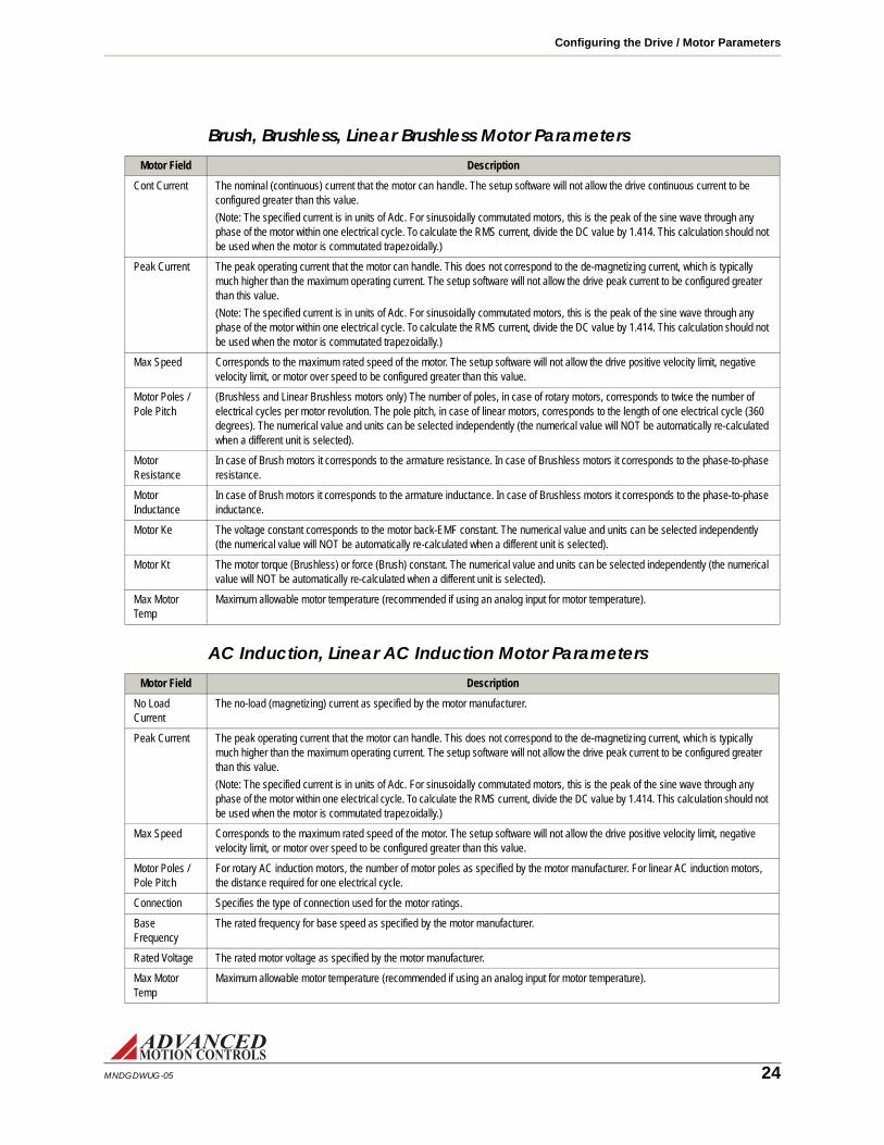
Brush, Brushless, Linear Brushless Motor Parameters
AC Induction, Linear AC Induction Motor Parameters
Motor Field Description
Cont Current The nominal (continuous) current that the motor can handle. The setup software will not allow the drive continuous current to be configured greater than this value.
(Note: The specified current is in units of Adc. For sinusoidally commutated motors, this is the peak of the sine wave through any phase of the motor within one electrical cycle. To calculate the RMS current, divide the DC value by 1.414. This calculation should not be used when the motor is commutated trapezoidally.)
Peak Current The peak operating current that the motor can handle. This does not correspond to the de-magnetizing current, which is typically much higher than the maximum operating current. The setup software will not allow the drive peak current to be configured greater than this value.
(Note: The specified current is in units of Adc. For sinusoidally commutated motors, this is the peak of the sine wave through any phase of the motor within one electrical cycle. To calculate the RMS current, divide the DC value by 1.414. This calculation should not be used when the motor is commutated trapezoidally.)
Max Speed Corresponds to the maximum rated speed of the motor. The setup software will not allow the drive positive velocity limit, negative velocity limit, or motor over speed to be configured greater than this value.
Motor Poles / Pole Pitch
(Brushless and Linear Brushless motors only) The number of poles, in case of rotary motors, corresponds to twice the number of electrical cycles per motor revolution. The pole pitch, in case of linear motors, corresponds to the length of one electrical cycle (360 degrees). The numerical value and units can be selected independently (the numerical value will NOT be automatically re-calculated when a different unit is selected).
Motor Resistance
In case of Brush motors it corresponds to the armature resistance. In case of Brushless motors it corresponds to the phase-to-phase resistance.
Motor Inductance
In case of Brush motors it corresponds to the armature inductance. In case of Brushless motors it corresponds to the phase-to-phase inductance.
Motor Ke The voltage constant corresponds to the motor back-EMF constant. The numerical value and units can be selected independently (the numerical value will NOT be automatically re-calculated when a different unit is selected).
Motor Kt The motor torque (Brushless) or force (Brush) constant. The numerical value and units can be selected independently (the numerical value will NOT be automatically re-calculated when a different unit is selected).
Max Motor Temp
Maximum allowable motor temperature (recommended if using an analog input for motor temperature).
Motor Field Description
No Load Current
The no-load (magnetizing) current as specified by the motor manufacturer.
Peak Current The peak operating current that the motor can handle. This does not correspond to the de-magnetizing current, which is typically much higher than the maximum operating current. The setup software will not allow the drive peak current to be configured greater than this value.
(Note: The specified current is in units of Adc. For sinusoidally commutated motors, this is the peak of the sine wave through any phase of the motor within one electrical cycle. To calculate the RMS current, divide the DC value by 1.414. This calculation should not be used when the motor is commutated trapezoidally.)
Max Speed Corresponds to the maximum rated speed of the motor. The setup software will not allow the drive positive velocity limit, negative velocity limit, or motor over speed to be configured greater than this value.
Motor Poles / Pole Pitch
For rotary AC induction motors, the number of motor poles as specified by the motor manufacturer. For linear AC induction motors, the distance required for one electrical cycle.
Connection Specifies the type of connection used for the motor ratings.
Base Frequency
The rated frequency for base speed as specified by the motor manufacturer.
Rated Voltage The rated motor voltage as specified by the motor manufacturer.
Max Motor Temp
Maximum allowable motor temperature (recommended if using an analog input for motor temperature).
MNDGDWUG-05 24

Configuring the Drive / Motor Parameters
3.4.3 Feedback TypeThe Feedback Type area holds information about the motor feedback device. The feedback device and parameters listed will be dependent on the drive model and the firmware currently used in the drive.• The primary feedback device will be shown along with the configurable parameters.• For universal feedback drives, the present primary feedback device will be shown as a selection option.— To change the primary feedback device, choose the new type of feedback from the selections. A message will appear stating that a firmware change is required to support the selected feedback device. Click ’OK’ to open the Firmware Download window to download the required firmware into the drive.— Once the download is complete, return to the Motor window, and the primary feedback device will reflect the firmware change.The parameters for each type of feedback device are as follows:Incremental Encoder Feedback Parameters
Motor Power Motor power as specified by the motor manufacturer.
Phase Parameters
Selects either Equivalent Circuit or Name Plate Parameters. The selected item will display the phase parameters associated with that item.
Equivalent Circuit
- R1: as determined by the motor’s equivalent circuit model
- R2: as determined by the motor’s equivalent circuit model
- X1: as determined by the motor’s equivalent circuit model
- X2: as determined by the motor’s equivalent circuit model
- Xm: as determined by the motor’s equivalent circuit model
Name Plate Parameters
- Stator Resistance: The stator transient resistance as specified by the motor manufacturer.
- Stator Transient Inductance: The stator transient inductance as specified by the motor manufacturer.
Rated Speed The rated speed as specified by the motor manufacturer.
Power Factor The power factor as specified by the motor manufacturer.
Efficiency The motor efficiency as specified by the motor manufacturer.
Field Description
Polarity Represents the polarity of the selected feedback device signal. AutoCommutation will determine the polarity.
Resolution Represents the counts per revolution (counts/rev) for a rotary motor, or the counts per distance (counts/in or counts/mm, depending on the units selected for pole pitch) for a linear motor.
Index / Ref Marker
Indicates if there is an encoder index pulse.
Indices/Rev The number of index occurrences per revolution (number of lines per index occurrence for linear motor).
Motor Field Description
MNDGDWUG-05 25

Configuring the Drive / Motor Parameters
1Vp-p Sin/Cos Encoder / Absolute Encoder Feedback Parameters
Resolver Feedback Parameters
3.4.4 CommutationThe commutation section allows configuration of basic commutation settings. The available settings will depend on the type of motor and feedback in use:
Field Description
Polarity Represents the polarity of the selected feedback device signal. AutoCommutation will determine the polarity.
Serial Interface (Absolute Encoder only) Selects the serial interface for the absolute encoder in use (Unassigned, Hiperface, or EnDat).
Abs Range (Absolute Encoder only) Represents the number of absolute steps per revolution for the absolute encoder. Must be a multiple of the Encoder Cycles/Rev value.
Resolution Represents the encoder cycles per revolution (counts/rev) for a rotary motor, or the encoder cycles per distance (counts/in or counts/mm, depending on the units selected for pole pitch) for a linear motor.
Interpolation The interpolation is configurable in powers of 2 from 1 to 512 lines per Sin/Cos cycle. Represents the Sin/Cos interpolation of the position loop which determines how many counts are defined per encoder cycle. The number of counts per cycle is the interpolation value multiplied by 4, giving an interpolated encoder resolution from 4 to 2048 counts per Sin/Cos cycle.
Index / Ref Marker
Indicates if there is an encoder index pulse.
Indices/Rev The number of index occurrences per revolution (number of lines per index occurrence for linear motor).
Field Description
Polarity Represents the polarity of the resolver. AutoCommutation will determine the polarity.
Carrier Frequency
Displays the frequency of the resolver excitation signal
Amplitude Displays the amplitude of the resolver excitation signal
Resolution Specify either Low or High resolution. Low (12-bit) means an equivalent 4096 counts/rev. High (14-bit) means an equivalent 16384 counts/rev.
Field Description
Commutation Sensors (Halls)
Indicates that commutation sensors are to be used.
Commutation Angle
Selects the Hall phasing angle. Note that the Hall phasing angle will be automatically selected after running AutoCommutation. If the Hall sensor phasing differs from 60º or 120º by more than 10 electrical degrees, "Other" will be automatically selected.
Trapezoidal / Sinusoidal
Selects between Trapezoidal or Sinusoidal commutation. Trapezoidal is disabled for Resolver and Absolute Encoder feedback, and is only enabled for other types of feedback if Commutation Sensors is checked and a valid Commutation Angle of 60º or 120º is selected.
MNDGDWUG-05 26

Configuring the Drive / Motor Parameters
3.4.5 BrakingThe Brake checkbox allows a brake to be assigned with an event action. The brake can be assigned to a digital output in the Digital Outputs window. Checking or unchecking the Brake checkbox may result in certain event actions changing. Look in the Advanced Events window to view the assignments. The following event actions will be affected:• When "Brake" is checked, events configured for "Disable Bridge" or "Dynamic Brake" will be changed to "Apply Brake and Disable Bridge" or "Apply Brake and Dynamic Brake", respectively.• When "Brake" is unchecked, events configured for "Apply Brake and Disable Bridge" or "Apply Brake and Dynamic Brake" will be changed to "Disable Bridge" or "Dynamic Brake", respectively.In addition, the brake output can be configured to use delays between external braking and enabling/disabling the drive. This delay is designed to prevent loads from falling or coasting when the effects of gravity or other external forces are seen in the system.
Reset Commutation
Reset Commutation is used primarily for systems unable to complete AutoCommutation that need commutation angles set to known good angles.
- If the existing commutation setting is 120º, Reset Commutation will reset the commutation angles to the drive default angles for 120º phasing.
- If the existing commutation setting is 60º, Reset Commutation will reset the commutation angles to the drive default angles for 60º phasing.
- If the existing commutation setting is "Other", Reset Commutation will change the commutation angle to 120º and reset the commutation angles to the drive default angles for 120º phasing.
External Commutation Between Phases
Selects the two phases the drive will output current to when using a brush type motor.
Field Description
Brake Applied Delay
Delay after applying external brake before disabling power bridge or performing dynamic braking.
Brake Released Delay
Delay before releasing external brake after enabling power bridge or discontinuing dynamic braking.
Field Description
MNDGDWUG-05 27
Configuring the Drive / AutoCommutation
3.5 AutoCommutationThe AutoCommutation routine detects the motor feedback type and polarity, and then configures the drive commutation parameters appropriately.Before running AutoCommutation:
• Enter in the correct motor information in the Motor Parameters window.• Specify the correct feedback information.• Specify limits to protect the motor.• Tune the current loop.• De-couple the motor from any load and secure the motor. Sudden motion will occur!If you have not done the preceding, see the corresponding sections in this manual.See “AutoCommutation™” on page 50 for information on how to run the AutoCommutation routine.
MNDGDWUG-05 28

Configuring the Drive / Auxiliary Encoder Input
3.6 Auxiliary Encoder InputMost ADVANCED Motion Controls’ drives allow for an auxiliary encoder to be used to close the position loop in a dual loop application. The Auxiliary Encoder Input window under Encoder Options > Aux Encoder Input in the Setup Panel provides an interface to enter the auxiliary encoder information to ensure proper operation and to allow for an auxiliary index to be used for homing.In order for the auxiliary encoder to be used as the position feedback device, Auxiliary Encoder needs to be specified as the position loop feedback device in the Drive > Loop Feedback window.
3.6.1 Feedback ParametersConfigure the auxiliary encoder by entering the following specifications:Field Description
Encoder Type Select if the auxiliary encoder is linear or rotary.
Resolution Enter the resolution of the auxiliary encoder device.
Feedback Polarity
Select the polarity of the incoming auxiliary encoder signal.
Index Specify if an index is preset (required for homing to auxiliary index).
MNDGDWUG-05 29

Configuring the Drive / Encoder Output
3.7 Encoder OutputDrives that support a resolver, 1Vp-p Sin/Cos encoder, or Absolute encoder feature either a Buffered Encoder Output or an Emulated Encoder Output that emit a 5V square wave that can be used to synchronize the command to other axes or to close the position loop. The buffered encoder output has a 1:1 input-to-output ratio, while the emulated encoder input-to-output ratio is configurable.For resolver feedback the emulated output will match the resolver resolution setting. For example, selecting Low Resolution (12-bit) will give an equivalent 212 (4096) counts/rev at the output. There will be a small phase lag between the sinusoidal feedback to the drive and the emulated output due to the time required to process the emulated signal.The Divide Amount field sets a value by which the interpolated encoder resolution is divided to get the emulated encoder output resolution (counts/rev). The Emulated Index Position field allows you to specify an absolute position for the output index relative to the emulated output counts. Additionally, you may select to have this index repeat for every specified number of output counts in the Emulated Index Period field. The index period is specified as the number of emulated counts between emulated indices. The index period must be zero, or divisible by 4. If zero is used, the effective period will be 232 emulated counts.For Sin/Cos feedback, the emulated output will be re-initialized each time the absolute position of the drive is initialized (i.e. via homing, Set Position, etc.). Until the drive position is initialized, no emulated index will be output by the drive.
MNDGDWUG-05 30

Configuring the Drive / Inputs / Outputs
3.8 Inputs / OutputsInputs / Outputs allows configuration and diagnostics of all digital and analog programmable inputs and outputs.The following tabs are available:• Analog Inputs• Analog Outputs• Digital Inputs• Digital Outputs
3.8.1 Analog InputsEach programmable analog input can be assigned a certain drive function through the Command, Feedback, or Limits windows. When a function is assigned to an analog input, the Analog Inputs window will display the assignment, the configuration settings, and the currently measured value. Analog Inputs cannot be assigned to a function in the the Analog Inputs window.Check the drive datasheet to find the number of available analog inputs.Each assigned input can be scaled, according to the selected function, to provide an optimal range by entering a value in the "Scale" column. Entering the numerical value of the chosen function for a 1V input signal performs the scaling. An offset (in volts) can also be defined.A programmable deadband can be configured for analog inputs assigned to the command source. The deadband sets a voltage range which will have no effect on the command. This is particularly useful when the analog command source is configured to control velocity.The drive handles anything within the deadband range as zero, and subtracts the deadband value from all other values. For example, with a deadband setting of ±100 mV, the drive ignores any signal between -100 mV and +100 mV.Selections become effective after clicking the Apply button.
0
100
-100
200
-200
Out
put (
mV
)
Input (mV)
0 100-100 200
Dead Band
Note
MNDGDWUG-05 31

Configuring the Drive / Inputs / Outputs
3.8.2 Analog OutputsEach programmable analog output can be assigned to a certain drive variable.Each output can also be scaled, according to the selected variable, to provide an optimal range. Entering the numerical value of the chosen variable for a 1V output signal performs the scaling. An offset (in volts) can also be defined.
Check the drive data sheet to find the number of available analog outputs. A list of available output signals and their definitions can be found in “Signal Definitions” on page 77.3.8.3 Digital InputsTo assign a function to a digital input, drag-and-drop one or more functions from the Input
Functions field to the desired digital input in the Input Assignments field. Capture functions may only be assigned to High Speed (HS) digital inputs, while other functions may be assigned to either General Purpose (GP) or High Speed digital inputs. The Capture Edit button allows configuration of capture signals through the Capture Configuration Window.The present status of each input is displayed by the LED graphic beside each digital input number (clear = Not Active, green = Active). The Active column displays the input polarity. Active Low means the input must be pulled-down for the input to be considered ON. Set the input polarity by selecting either the Active Low or Active High button at the bottom of the window. Each input can be assigned to one or more functions. If more than one function is assigned to a single input, the following priority rules apply (from highest to lowest):1. Inhibit2. Dynamic brake3. Positive or negative limit4. Phase DetectionThe User Disable, User Aux Disable, and the Motor Over Temperature functions depend on the selected function in the Events windows.Functions can be removed from a digital input by highlighting the selected function, then hitting Delete on the keyboard, or the button in the Digital Inputs window.
Selections become effective after clicking the Apply button.
Selections become effective after clicking the Apply button.
Note
Note
MNDGDWUG-05 32

Configuring the Drive / Inputs / Outputs
Capture Configuration Window
3.8.4 Digital OutputsTo assign a function to a digital output, drag-and-drop one or more functions from the Output Functions field to the desired digital output in the Output Assignments field.The present status of each output is displayed by the LED graphic beside each digital output number (clear = Not Active, green = Active). The Active column displays the output polarity. Active High means the output is pulled-down if the output is considered OFF. Set the output polarity by selecting either the Active Low or Active High button at the bottom of the window.Each output can be assigned one or more functions. If more than one function is assigned to a single output, the functions are OR-ed, which means that if one of the functions is true, the output will be turned ON. Functions can be removed from a digital output by highlighting the selected function, then hitting Delete on the keyboard, or the button in the Digital Outputs window.
Captured Signal This field shows the selected signal to be captured.
Captured Value This shows the last value captured by the drive.
Trigger Edge You may select between Rising, Falling, or Both to set when the signal will be captured.
Trigger Mode Single mode will allow the signal to be captured only once per set/reset. Continuous will allow the signal to be captured any time it is triggered while capture is set.
Set / Reset Input Displays the Digital Input assigned to reset the capture signal.
Selections become effective after clicking the Apply button.
Note
MNDGDWUG-05 33

Configuring the Drive / Limits
3.9 Limits Limits allows configuration of general drive parameters.The following selections are available regardless of which loops are enabled:• Current• Velocity• Position• Stop• Voltage• Temperature
3.9.1 Current LimitsUse this window to set the drive output current limits within the hardware capabilities of the drive.
The drive can output its rated peak current for a maximum of 2 seconds with a foldback time within 10 seconds. This defines the maximum current capability curve. Current profiles that intersect with the maximum current capability curve will be limited to stay within this envelope.
The specified current is in units of peak current. This is the peak value allowed to go through any phase of the motor within one electrical cycle. To calculate the RMS current, divide the peak value by 1.414. This calculation should not be used when the motor is commutated trapezoidally. For an in-depth explanation of how the drive limits current, see “Current Limiting” on page 82.
Peak Current Maximum output current (limited output time).
Peak Current Time The maximum time duration of peak current.
Continuous Current The maximum continuous current level the drive will output.
Foldback Time The time the drive will use to reduce the current to the continuous current level setting.
Current Limiting Algorithm Selects between Time-Based Limiting or RMS Charge-Based Limiting (for supported drive models only). RMS Charge-Based Limiting will allow the drive to output more continuous current during motor movement. See “Current Limiting Algorithm” on page 86 for detailed information on current limiting.
Current Limit Scaling Source
You may assign an input to change the current limit dynamically. The scaling value can be adjusted in the I/O Configuration window (see “Inputs / Outputs” on page 31).
Note
MNDGDWUG-05 34

Configuring the Drive / Limits
3.9.2 Velocity LimitsThe following velocity-related limits can be set:
3.9.3 Position LimitsThe following position-related limits can be set:
3.9.4 StopThe Stop window configures software deceleration behavior. This field controls the deceleration limit for all stop actions and direction stops. If the drive is controlling velocity or position, the load decelerates according to the user-defined deceleration limit. If the drive is controlling current, the drive will command zero current with no deceleration control.Events that trigger the Stop function can be configured in “Events” on page 39. Be sure to use deceleration values that are realistic and physically possible given the system constraints. For example, the more inertia a motor has, the longer it will take to stop. If you try to use limits that are not physically possible, the motor may move unpredictably during the deceleration period.
Motor Over Speed The maximum speed in which the motor should be able to go. The action following a motor overspeed event can be defined in Event Manager (active in all operating modes).
Zero Velocity Window The measured velocity values, within which the motor is considered to be at zero velocity (active in all operating modes).
At Velocity Window The "At Velocity" event will be set when the measured velocity reaches the target velocity, within the "At Velocity" window (active in velocity mode only).
Velocity Following Error The maximum allowed velocity error (difference between target velocity and measured velocity), prior to setting the "Velocity Following Error" event (active in velocity mode only).
Positive Velocity Limit The maximum allowed demand velocity in the positive direction (active only when the velocity loop is closed).
Negative Velocity Limit The maximum allowed demand velocity in the negative direction (active only when the velocity loop is closed).
In-Home Position Window Defines a window around the Home Position Value, such that when the measured position is within this window, the At-Home Position event will be active.
In-Position Window Defines a window around the target position, such that when the measured position is within this window, the At Command event will be active.
Position Following Error Window
The maximum allowed position error (difference between target position and measured position) prior to setting the "Position Following Error" event (active in position mode only).
Home Position Value Position value of the home position. When the measured position reaches this position, within the In-Home Position Window, the At-Home event becomes active.
Max Measured Position Limit
Maximum allowed measured position. The Max Measured Position event will become active if the measured position exceeds this value.
Min Measured Position Limit
Minimum allowed measured position. The Min Measured Position event will become active if the measured position exceeds this value.
Max Target Position Limit Maximum allowed target position. The Max Target Position event will become active if the target position exceeds this value.
Min Target Position Limit Minimum allowed target position. The Min Target Position event will become active if the target position exceeds this value.
Disable Position Limits Checkbox
Allows you to disable position limits so the motor has no maximum or minimum position value.
MNDGDWUG-05 35

Configuring the Drive / Limits
3.9.5 Voltage LimitsUse this window to set the User Under- and Over-Voltage limits. These limits are restricted to fall within the hardware capability of the drive. The Nominal DC Bus Voltage should contain the normal operating DC voltage supplied to the drive. If using an AC input drive, the Nominal DC Bus voltage is equal to the AC voltage multiplied by 1.41.Shunt regulator operationThe shunt regulator (if available, depending on drive model) can be enabled/disabled and its turn-on voltage can be set at any given voltage below the hardware over-voltage limit of the drive. The internal shunt-resistor parameters, if present, are displayed.If the drive has provision for connection of an external shunt resistor, the parameters for that resistor can be entered. If that provision is not available, these fields will not be available. Check the data sheet for your drive to see if an external shunt resistor can be connected.The shunt regulator method is used to dissipate excess energy during periods of rapid deceleration. In most cases, this energy can be consumed in a matter of milliseconds. If a longer regeneration time is needed, the drive will limit the output to the resistor according to the following information.• Measured Bus Voltage• Shunt resistor Power• Shunt resistor Resistance• Shunt resistor Inductance (if unknown, use zero)
If the stated resistor power or resistance is incorrect, the drive cannot reliably regulate the power dissipated.
There is a limit to the amount of current the drive can output to the shunt without damaging the circuitry. The resistance of the external resistor should be large enough to handle this current. Follow the table below to determine the absolute minimum resistance that the shunt circuitry can handle.
Drive Power Module Minimum Shunt Resistance (Ohms)
015A400 N/A
030A400 20
060A400 10
100A400 10
030A800 Consult Factory
060A800 40
Note
MNDGDWUG-05 36

Configuring the Drive / Limits
External shunt resistor power selectionDuring a regenerative event, the shunt output will initially turn on for 10ms, and the entire bus voltage is placed across the shunt resistor to allow the excess bus voltage to fall below the shunt enable threshold during normal regeneration.
After this initial pulse, if the bus voltage is still higher than the shunt turn on voltage, the shunt output will turn on and off rapidly in order to regulate the power dissipated. For both external and dual shunt modes, the on time and period are adjusted such that the shunt is on for approximately 3 time constants while maintaining the same duty cycle. The highest duty cycle attainable is 50%. The drive sets the on-time PWM output to a duty cycle such that:Vbus = measured bus voltage (Vdc)R = shunt resistance (ohms) - specified in setup software for
external shuntPmax = maximum shunt power (W) - specified in setup software for
external shuntDC = PWM duty cycleThe period of the PWM output is set as [Vbus2/(R * Pmax)] * Ton, with Ton=2/Fs, where Fs is the switching frequency of the drive (Hz). The average current going through the shunt resistor will be less than or equal to Vbus/2R. The average power through the shunt resistor during this time will be less than or equal to (Vbus)2/4R.
This initial turn-on is independent of the shunt resistor information entered; therefore the power dissipated through your shunt resistor may exceed the rated power during the first 10ms. If using an external shunt resistor, be sure the resistor can handle this 10ms pulse.
Vbus2
R----------- DC Pmax=×
MNDGDWUG-05 37
Configuring the Drive / Limits
3.9.6 Temperature LimitsThe Temperature Limits tab allows configuration of an external temperature sensor. Configuration options are dependent upon the specific drive hardware. Certain drives accept an external temperature sensor in the form of either a switch or a thermistor. Use the "Sensor Type" pull down list to select the type of sensor in use.SwitchFor applications using a switch as an external temperature sensor, select whether the Motor Over Temperature event will occur when the switch is open or closed.ThermistorFor applications using a thermistor as an external temperature sensor, input the resistance value when Motor Over Temperature will activate, and at what resistance Motor Over Temperature will become inactive. Acceptable input values range from 0 to 5000 Ω. Both negative thermal coefficient (NTC) and positive thermal coefficient (PTC) thermistors are supported. The setup software will automatically determine the thermistor type based on the values entered in the Event Action fields.If the Event Action Active Level is greater than or equal to the Event Action Inactive Level, then:• The Motor Over Temperature event will turn on when the resistance becomes higher than the Event Action Active Level.• The Motor Over Temperature event will turn off when the resistance becomes lower than the Event Action Inactive Level.If the Event Action Active Level is set less than the Event Action Inactive Level, then:• The Motor Over Temperature event will turn on when the resistance becomes lower than the Event Action Active Level.• The Motor Over Temperature event will turn off when the resistance becomes higher than the Event Action Inactive Level.Other drives are capable of accepting an analog temperature sensor that can be connected to an analog input of the drive. You can configure a maximum allowable motor temperature at which point the drive will be disabled. The motor temperature level at which the drive can be re-enabled can also be configured. For a digital temperature sensor, see the digital inputs section of “Inputs / Outputs” on page 31.
MNDGDWUG-05 38

Configuring the Drive / Events
3.10 EventsThe Basic and Advanced Events windows let you configure or review actions associated with certain drive events. For a full list of drive events and recommended troubleshooting methods, see “Events and I/O Descriptions and Troubleshooting Methods” on page 102.The diagrams below illustrate the behavior of an event and the corresponding event action.
The Event Actions that can be assigned to drive events are as follows (note that not all event actions are available for each event):Event Action Description
No Action Event Action is disabled
Disable Power Bridge
No power is delivered to the motor. Motor is allowed to move freely.
Disable Positive Direction
Disables the drive from outputting to the motor in the positive direction, while allowing commanded motion in the negative direction. The result is dependent on the mode of operation. This action is not recommended in vertical applications because the load will be free to fall once the limit is activated. For vertical loads, we recommend using 'Positive Stop'.
Disable Negative Direction
Disables the drive from outputting to the motor in the negative direction, while allowing commanded motion in the positive direction. The result is dependent on the mode of operation.
Dynamic Brake Motor leads are virtually shorted together internally. However, the bridge enables to protect motor by regulating motor current.
Positive Stop If the drive is controlling velocity or position, the load decelerates according to the deceleration limit specified in the Stop Limits window. If the drive is controlling current, the drive will command zero current with no deceleration control. Commanded motion in the positive direction has no affect. Motor continues to servo with zero command in the positive direction.
Negative Stop If the drive is controlling velocity or position, the load decelerates according to the deceleration limit specified in the Stop Limits window. If the drive is controlling current, the drive will command zero current with no deceleration control. Commanded motion in the in the negative direction has no affect. Motor continues to servo with zero command in the negative direction.
Stop If the drive is controlling velocity or position, the load decelerates according to the deceleration limit specified in the Stop Limits window. Commanded motion has no affect. Motor continues to servo with zero command.
Apply Brake then Disable Bridge
Brake output is turned on, and then the bridge is disabled. The delay is set in the Braking window.
Apply Brake then Dynamic Brake
Brake output is turned on, and then the dynamic brake is applied. The delay is set in the Braking window.
MNDGDWUG-05 39

Configuring the Drive / Events
3.10.1 Basic EventsThe Basic Events window allows for simple configuration of some common drive events. Select an Event Action from the drop-down lists for each drive event.• Latch: If the latch box is checked, the selected Event Action will remain active until the event is removed or you perform one of these actions:— Cycle power to the drive— Refresh the Drive Status
3.10.2 Advanced EventsThe Advanced Events window allows in-depth customization of the way the drive responds to certain drive events. Events under Advanced Settings can correspond to one of the following groups.Group Description
Fault Critical events that result in the drive being disabled.
User Action Event actions that are activated via a digital input or other external interface.
Software Action Event actions that are a result of an internal event.
Motor Events directly related to the motor.
Feedback Events directly related to the motor feedback signals.
Command Events related to the command source or command signal.
Current Events related to the current output as measured by or limited by the drive.
Velocity Events related to the velocity as measured by or limited by the drive.
Position Events related to the position as measured by or limited by the drive.
Shunt Applicable to drives that support a shunt regulator only. Event indicates when the shunt regulator is active.Each event has several programmable attributes that can be edited by clicking on an event row:• Delay: The time delay between the actual occurrence of the event and the event action.• Action: The action to be taken by the drive after the response time has elapsed. For safety reasons some actions are not available with some events.• Recovery: The time after which the selected event action will be removed when the cause of the event is no longer present.• No Repeat: The time, after the recovery time and subsequent removal of the event action, during which the drive will NOT consider an occurrence of the event as a new occurrence. The Event Action will still be applied in case an event does occur within this window. However, that occurrence will not be counted as a new occurrence with regard to the Maximum Recoveries attribute.• Recoveries: The number of occurrences of the event prior to a permanent event action. The number of recoveries can be set to a specific value, or to Latch or Unlimited.
MNDGDWUG-05 40
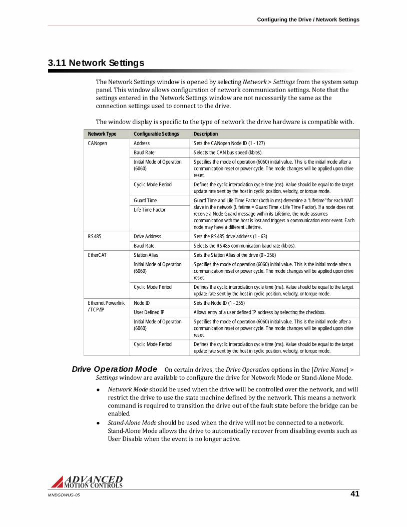
Configuring the Drive / Network Settings
3.11 Network SettingsThe Network Settings window is opened by selecting Network > Settings from the system setup panel. This window allows configuration of network communication settings. Note that the settings entered in the Network Settings window are not necessarily the same as the connection settings used to connect to the drive.The window display is specific to the type of network the drive hardware is compatible with.
Drive Operation Mode On certain drives, the Drive Operation options in the [Drive Name] > Settings window are available to configure the drive for Network Mode or Stand-Alone Mode.• Network Mode should be used when the drive will be controlled over the network, and will restrict the drive to use the state machine defined by the network. This means a network command is required to transition the drive out of the fault state before the bridge can be enabled.• Stand-Alone Mode should be used when the drive will not be connected to a network. Stand-Alone Mode allows the drive to automatically recover from disabling events such as User Disable when the event is no longer active.
Network Type Configurable Settings Description
CANopen Address Sets the CANopen Node ID (1 - 127)
Baud Rate Selects the CAN bus speed (kbit/s).
Initial Mode of Operation (6060)
Specifies the mode of operation (6060) initial value. This is the initial mode after a communication reset or power cycle. The mode changes will be applied upon drive reset.
Cyclic Mode Period Defines the cyclic interpolation cycle time (ms). Value should be equal to the target update rate sent by the host in cyclic position, velocity, or torque mode.
Guard Time Guard Time and Life Time Factor (both in ms) determine a "Lifetime" for each NMT slave in the network (Lifetime = Guard Time x Life Time Factor). If a node does not receive a Node Guard message within its Lifetime, the node assumes communication with the host is lost and triggers a communication error event. Each node may have a different Lifetime.
Life Time Factor
RS485 Drive Address Sets the RS485 drive address (1 - 63)
Baud Rate Selects the RS485 communication baud rate (kbit/s).
EtherCAT Station Alias Sets the Station Alias of the drive (0 - 256)
Initial Mode of Operation (6060)
Specifies the mode of operation (6060) initial value. This is the initial mode after a communication reset or power cycle. The mode changes will be applied upon drive reset.
Cyclic Mode Period Defines the cyclic interpolation cycle time (ms). Value should be equal to the target update rate sent by the host in cyclic position, velocity, or torque mode.
Ethernet Powerlink / TCP/IP
Node ID Sets the Node ID (1 - 255)
User Defined IP Allows entry of a user defined IP address by selecting the checkbox.
Initial Mode of Operation (6060)
Specifies the mode of operation (6060) initial value. This is the initial mode after a communication reset or power cycle. The mode changes will be applied upon drive reset.
Cyclic Mode Period Defines the cyclic interpolation cycle time (ms). Value should be equal to the target update rate sent by the host in cyclic position, velocity, or torque mode.
MNDGDWUG-05 41

Configuring the Drive / PDO Configuration
3.12 PDO ConfigurationThe PDO Configuration windows are available for drives that support the CANopen communication protocol and are opened by selecting the appropriate option under the Network heading in the system setup panel.The PDO Configuration windows allow the configuration of PDO mapping assignments, and the option of exporting the project file as a .DCF (CANopen drives) file by clicking the Export DCF button.
3.12.1 RPDOs - CAN DriveThe CAN drive RPDO mappings are pre-configured and cannot be changed in the setup software. However, each RPDO can be manually enabled or disabled in one of two ways:• Click on the Load Preset button to select a pre-determined RPDO configuration.• Select the desired RPDO in the Object Assignments box, then check or uncheck the PDO
Enabled checkbox.The PDO Settings box allows further RPDO configuration:
3.12.2 TPDOs - CAN DriveThe CAN drive TPDO configuration and settings controls function in the same way as the RPDOs (“RPDOs - CAN Drive” on page 42) with the addition of RTR and period configuration.Setting Description
RTR Allowed Allow or disallow RTR (Remote Transmission Request) access for the selected TPDO
COB-ID Enter the COB-ID for the selected TPDO (181h - 57fh)
Transmission Type Set the transmission type for the selected TPDO
Period For Sync Cyclic transmission type, enter the number of sync pulses for the selected TPDOExcept for TPDO 26, the CANopen TPDO mappings are pre-configured and cannot be changed in the setup software. TPDO 26 can hold up to eight objects, or 64 bits. The number of objects that can be assigned will be limited by the size of the objects.To map an object to TPDO 26, drag an object from the Available Objects box over to the Object Assignments field. Objects will be relegated to TPDO 26 automatically in the order in which they are assigned. To change the order of a selected object assigned to TPDO 26, use the and buttons. The button will remove the selected object from TPDO 26.The Mapping Capacity bar displays how much space remains for objects to be assigned to TPDO 26.
Setting Description
COB-ID Enter the COB-ID for the selected RPDO (181h - 57fh)
Transmission Type Set the transmission type for the selected RPDO
MNDGDWUG-05 42

Configuring the Drive / PDO Configuration
3.12.3 TPDO Events - CAN DriveThe CAN drive TPDO Events tab is used to assign TPDOs to specific events. Drag TPDOs from the Available PDOs box to one of the event fields. By clicking on a desired event, the Event Settings box can then be used to further configure the event, or to remove the assigned TPDO(s).Timer EventsSets the cycle time of the assigned TPDOs. If the cycle time is set to 0, the assigned TPDOs will be transmitted continuously.Bit Monitor EventsThe Bit Monitor identifies an object which is observed continuously. Select an object from the Observed Object drop down box. If the observed bits change the TPDO(s) assigned to the Bit Monitor will be sent. The observed bits are defined by the Bit Mask field (0 to FFFF in hex).Value EventsThe Value Changed event observes an object continuously, defined by the Observed Object drop down box. If the object changes by the user defined value entered into the Target Value field the assigned TPDO(s) will be sent.The Value Reached event observes an object continuously, defined by the Observed Object drop down box. If the object reaches the user defined value entered into the Target Value field in the selected Direction, the assigned TPDO(s) will be sent.
3.12.4 RPDOs and TPDOs - Ethernet Powerlink or EtherCATWhen using an Ethernet Powerlink or EtherCAT network, up to 16 words can be mapped to the RPDO and TPDO. A 16-bit object will take up 1 word, and a 32-bit object will take up 2 words. Objects can be assigned in one of two ways:• Click on the Load Preset button to select a pre-determined RPDO or TPDO configuration.• Drag-and-drop objects from the Available Objects field to the Object Assignments field. Use the , , and buttons to change the order or remove assigned objects.
MNDGDWUG-05 43

Configuring the Drive / Tuning
3.13 TuningThe selections under Tuning in the Setup Panel are used to set the control loop gains and configure filters and other tuning tools.3.13.1 Current Loop GainsThere are two options for current loop (torque and flux) parameters:
• Proportional Gain and Integral Gain: Set the gain values according to conventional PI tuning rules.• Propotional Gain and Motor Pole: Use for zero-placement in the current loop algorithm. The proportional gain setting is the overall gain of the current loop algorithm. When the Motor Pole value matches the actual motor electrical pole (the inverse of the motor electrical time constant), a critically damped response can be obtained with the largest overall proportional gain.The Calculate button can be used to automatically set the current loop gains based on the values entered in the Motor and Limits windows. Typically these values will provide a good starting point and further gain adjustment is required for optimal tuning. Make sure proper motor and application data are entered prior to using this function.
3.13.2 Gain SetsFor a motion control system to work properly, the drive must be correctly tuned to the motor and/or system. This is accomplished with a set of gain values for each of the control loops in the drive. Most applications will not require gain switching, and therefore should use the default Gain Set 0. However, more than one set of gains may be required as the machine mechanics may change shape (effecting inertia) or the system is loaded or unloaded. The setup software allows the configuration of two separate sets of gain values, Gain Set 0 and Gain Set 1. Each gain set can be assigned to either Configuration 0 or Configuration 1 in the Configuration window.To set the gain values, access the Gain Set windows by clicking on Tuning > Gain Set 0 or Gain Set 1 from the Setup Panel. Note that Gain Switching must be enabled in order for Gain Set 1 to be available to edit. Gain Switching can be enabled in the Drive Settings window (Drive > Settings). For a step-by-step guide to tune the drive to the system, see “Tuning and Commutation” on page 46.The Gain Set values can be set according to conventional PID tuning rules:
Proportional Gain (Kp) Increase for faster response and increased stiffness. Excessive proportional gain can cause overshoot and oscillation.
Integral Gain (Ki) Increase to eliminate steady-state error and increase accuracy (i.e. amount torque/force per deflection). Excessive integral gain can cause instability and jitter.
Derivative Gain (Kd) Increase to dampen response and reduce overshoot. Excessive derivative gain results in a more sluggish response. Depending on the feedback source, it may cause excessive jitter and noise.
MNDGDWUG-05 44

Configuring the Drive / Tuning
Set Position The Set Position function will change the value of the measured position and target position to the values defined in the "Preset Position" field. It is recommended to use the Set Position feature to avoid unexpected motor movement when enabling the bridge, as a large difference between the measured and target position may cause the motor to spin rapidly upon receiving power.3.13.3 Advanced SettingsThe Advanced Settings window (Tuning > Advanced Settings) allows configuration of the Velocity and Position Integrator Decay functions.
Parameter Description
Integrator Decay Enabling Integrator Decay will reduce the integrator output each sampling cycle by the specified rate (0-100%) of the Integral Gain. This prevents the integrator from commanding a high current while trying to resolve a small error signal in high stiction applications. When Velocity Integrator Decay is enabled, decay will trigger if the velocity error going into the integrator is within the specified decay Active Window. When Position Integrator Decay is enabled, decay will trigger if the position error is within the specified decay Active Window.
3.13.4 FiltersThe Filters tab (Tuning > Filters) allows configuration of additional gain parameters that can be used for more in-depth loop tuning behavior. Note that the values entered in the Filters window will effect both Configuration 0 and Configuration 1: Parameter Description
Feedback Filter Cut-off Frequency Sets the cutoff frequency for the velocity feedback filter. This low-pass filter reduces velocity ripple (due to digitization). However, this will also affect closed loop performance. A typical setting is between 50 Hz and 1500 Hz.
Low Speed Smoothing
(incremental encoder feedback only)
When using a standard incremental encoder, Low Speed Smoothing stabilizes the velocity loop during low-speed movement. To tune the low speed gain, use the Waveform Generator to command a low speed (1 or 2 rpm) and look at the velocity measured with the oscilloscope. Adjust the low speed gain to minimize the velocity spike as seen by the scope. Alternatively, this gain can be used to reduce jitter when position is tuned around the velocity loop.
Accel Feed Forward (Aff) Creates a direct current demand, based on the change in velocity demand (Velocity Loop) or the second derivative of the position demand (Position Loop). This gain does not affect closed loop behavior, but can help improve velocity/position-tracking capability.
Velocity Feed Forward (Vff)
(Position Loop only)
Creates a direct velocity demand based on the change in position demand. This gain does not affect closed loop behavior, but can help improve position-tracking capability.
MNDGDWUG-05 45

4 Tuning and Commutation
Before proceeding, you must accomplish the following actions: Configure the limits and events parameters Connect the motor power and feedback Drive tuning is a multi-step process that involves proper tuning of up to three different servo loops. Before tuning, the drive should have the appropriate parameters and limits configured as per the "Limits" on page 34. Following are the summary tasks you must perform; later in this chapter you will find the actual procedures with individual steps.
1. Current Loop Tuning: Once the drive parameters are configured properly, the current loop must be tuned. This is the innermost loop and forms the basis of all motion. You can select to have the current loop gains calculated based on motor and application data. This will typically provide a good starting point although some applications may require further refinement of the tuning parameters.
2. AutoCommutation™: This routine collects data on the motor and feedback parameters and asks the user to verify that they match what is entered into the Motor Data page. Some applications may have motors that cannot perform this routine due to mechanical constraints. It is possible to manually wire a motor for commutation. See "Manual Commutation Procedure" on page 52 if you must perform manual commutation.
Sudden motion may occur! Tuning should only be performed after you have specified motor information, drive limits and events, and user units.
Make sure the drive is disabled before selecting Calculate Gains.
It is crucial to make sure the motor is unloaded during commutation; any load applied to the motor will skew the results of the routine.
MNDGDWUG-05 46

Tuning and Commutation /
3. Velocity Loop Tuning: If you want to operate the drive in velocity mode, you must tune the current loop and set up the drive to commutate the motor (steps 1 and 2). A very tight current loop inside of a relatively tight velocity loop may cause audible noise. If maximum bandwidth is not necessary, de-tuning the current loop usually removes most of the audible noise. The velocity loop will have to be adjusted any time the current loop tuning is changed.4. Position Loop Tuning: You can either tune the position loop around the velocity loop, or around the current loop. Generally, it is much easier to tune a position loop around a velocity loop because only the proportional gain is needed. When tuning position around the current loop, a high derivative gain may be necessary on top of both proportional and integral gains.For a diagram of how the setup software control loop architecture is implemented, see "Control Loop Architecture" on page 97.
MNDGDWUG-05 47

Tuning and Commutation / Current Loop Tuning
4.1 Current Loop TuningBefore beginning current loop tuning, make sure that the motor is free to move and de-coupled from the load, as sudden motion may occur. The motor and drive limits information must be correctly specified in the Motor and Limits windows before tuning the current loop. For current loop tuning, the Loop Configuration in the active Configuration can be set to any of the available options.It is recommended to disable the drive by clicking on the Disable icon on the toolbar before beginning tuning. The procedure below will prompt you to enable the drive when necessary for tuning.Step 1: Inputs/Outputs Configuration setup
1. Select Inputs/Outputs >Digital Inputs from the Setup Panel.2. If an external Inhibit/Enable circuit is used during setup, assign the digital input that will be used to the User Disable function, and set the proper polarity (e.g., active high or active low).3. If no external Inhibit/Enable circuit is to be used during setup, then the Enable/Disable icons on the toolbar will be used to control drive enabling.
Step 2: Waveform Generator Setup
1. Open the Scope/Tuning tab by clicking on the Scope/Tuning icon from the toolbar.2. Select the Enabled checkbox in the Waveform Generator section to enable the Waveform Generator.3. Select the Square Waveform Type.4. Select the waveform target as Current Loop.5. Set Frequency to 100 Hz. If your motor has low inertia and is very responsive, use 150 Hz or 200 Hz.6. Ensure Offset is zero.7. Ensure Symmetry is 50%.8. Set the waveform amplitude to an appropriate value. Begin with 10% of the drive continuous current rating or 50% of the motor continuous current rating, whichever is lower.
Step 3: Oscilloscope setup 1. Select the Current oscilloscope preset from the Presets drop-down menu in the Scope/Tuning tab, or to manually configure the settings follow the steps below.2. Change the channel 1 signal to Current Target.3. Change the channel 2 signal to Current Measured.4. Change the Trigger Source to Current Target with the Level set to zero.5. Ensure Trigger Mode is Normal.6. Change Time/Div to either 1 msec or 500 μ sec.
MNDGDWUG-05 48

Tuning and Commutation / Current Loop Tuning
Step 4: Tuning 1. With the Scope/Tuning window still open, select Tuning > Current Loop Gains from the Setup Panel.2. In order to view the current loop gains and digital oscilloscope traces at the same time for real-time gain adjustment, with both the Scope/Tuning and Current Loop Gains tabs still open, select Window > New Vertical Tab Group from the menu bar to allow both tabs to be visible.3. To set starting values for proportional (Kp) and integral (Ki) gains, click the Calculate Gains button. Calculate Gains utilizes the values entered into the Motor Parameters, Feedback, and Limits windows. The specified motor inductance, resistance, and bus voltage determine the accuracy of the calculated values. If accurate data is not available, begin with Proportional Gain = 1 and the Integral Gain = 0.4. Enable the drive by clicking the Enable icon. The motor should emit an audible noise but remain still.5. Proper current loop tuning starts with zero integral gain while increasing the proportional gain until a 'knee' is formed (with no overshoot) in the Current Measured trace.
6. At this point, the proportional gain is done and the Integral gain must be slowly increased to close the steady state error between the Current Target and Current Measured traces.
7. Tuning changes with signal amplitude. Therefore you should now re-adjust the current amplitude in the Waveform Generator tab according to your most common application current requirements and re-tune. Contouring applications generally use small signal transients while point-to-point applications use larger signal transients.8. When current loop gain adjustments are complete, disable the drive .9. Disable the Waveform Generator to remove the command signal from the drive by unchecking the Enabled checkbox in the Waveform Generator field.10. Click Store on the toolbar to store the parameters to the drive’s nonvolatile memory.For reference, see "Current Limiting" on page 82.
MNDGDWUG-05 49

Tuning and Commutation / Commutation
4.2 CommutationMotor commutation is dependant on the type of motor and feedback available from the motor. Brushed motors have a commutator built into the motor housing; therefore the drive does not have to be configured to commutate them. Brushless DC (Trapezoidal), and AC (Sinusoidal), motors require a correctly configured drive to commutate.Commutation of a permanent magnet servomotor is the process that maintains an optimal angle between the permanent magnet field and the electromagnetic field created by the motor current(s). This process ensures optimal torque or force generation at any motor position, regardless of speed, for brushless motors.There are two ways to configure a digital drive to commutate a motor:• AutoCommutation™: Most applications can use the AutoCommutation routine for configur-ing a drive to a specific motor. This routine will detect the feedback devices attached to the motor and ask the user to verify them against the motor’s datasheet.• Manual Commutation requires more time, and may not be as accurate as AutoCommuta-tion. You will have to perform this method if:
— Your motor is mechanically restrained such that it is not free to move 2 revolutions + 1 electrical cycle in both directions (3 electrical cycles for a Brushless linear motor).— Your motor or load has a significant amount of inertia.— Your motor cannot be unloaded, or is a vertical load.— Your motor has a high degree of sticktion.
4.2.1 AutoCommutation™The AutoCommutation routine detects the motor feedback type and polarity, and then configures the drive commutation parameters appropriately.Brushless and linear motors with insufficient travel distance (two revolutions plus one electrical cycle for rotary motors, or three electrical cycles for linear motors) or large amounts of inertia will require the Manual Commutation Procedure instead. AutoCommutation detection is not required for brush-type motors.Before you run AutoCommutation, be sure you:
• Enter in the correct motor information in the Motor window page.• Specify the correct feedback information.• Specify limits to protect the motor.• Tune the current loop.• De-couple the motor from any load and secure the motor. Sudden motion will occur!If you have not done the preceding, see the corresponding sections in this manual.
MNDGDWUG-05 50
Tuning and Commutation / Commutation
For brushless and linear motors with sufficient travel distance, proceed as follows: 1. In Motor > Parameters, ensure that Sinusoidal Commutation is selected in the Commutation section of the window.2. Open the AutoCommutation window (Motor > AutoComm).3. If the drive is disabled, click the Enable icon to enable the drive.4. Click Start AutoCommutation to begin the process. During the AutoCommutation process, monitor the distance traveled in each direction. Rotary motors will turn two revolutions plus one electrical cycle in each direction. Linear motors will move three electrical cycles in each direction.5. When AutoCommutation is complete, select whether the motor has moved the proper distance or has not moved the proper distance. If the motor did not move the proper distance, verify the pole count or pole pitch in the motor parameters window.6. Once the motor has properly completed the AutoCommutation routine, verify the proper commutation and synchronization settings:
— Commutation:Trapezoidal - The drive uses Hall Sensors to commutate trapezoidally.Sinusoidal - The drive uses a feedback device to perform sinusoidal commutation.External Commutation (Brush) - The drive does not commutate the motor. Commutation is performed externally.
— Synchronization: (It is recommended to synchronize on the index any time that an index exists. This will allow the drive to home to an index. If a different method of synchronization is selected other than on the index, the drive will not be able to home to an index.)None - No synchronization is performed.Halls - each hall cycle - Synchronization is performed on every rising edge of Hall A.Index - Synchronization is performed on the rising edge of the encoder index pulse.
7. Click Apply from the toolbar to save the AutoCommutation parameters.8. Click the Store Settings icon to store parameters to non-volatile memory.
AutoCommutation™ Warnings After running AutoCommutation, it is possible that a warning (or warnings) may appear due to wiring errors or discrepancies between the information on the Motor Data page and the results of AutoCommutation.Follow these steps to successfully complete AutoCommutation:
For brushless motors with encoder only feedback, the Phase Detection function must be utilized whenever power to the drive is cycled or a loss of sinusoidal commutation occurs. See "Phase Detect" on page 55.
Note
MNDGDWUG-05 51

Tuning and Commutation / Commutation
1. Review the information in the AutoCommutation warning box, then select OK.2. Select ’Edit Motor Data’ from the options in the lower right hand corner.3. Click ’OK’ in the Pre-Loaded data dialog box.4. On the Motor Data page, the relevant information will have been changed to correspond with the AutoCommutation results. Click ’OK’, then click ’OK’ in any dialog boxes to return to the AutoCommutation window.5. Select ’Accept’ in the AutoCommutation window. If the ’Accept’ button is still grayed out, consult the general guidelines in the following table to diagnose and correct any AutoCommutation warnings, then re-run AutoCommutation.
4.2.2 Manual Commutation ProcedureThe large majority of applications do not require this method for configuring a drive to commutate the motor. A much easier method is provided in the setup software called AutoCommutation™. The procedure for manual commutation requires more time and may not be as accurate as the AutoCommutation method.Because some applications cannot use the AutoCommutation method, each drive defaults to a standard switching sequence that will commutate one of the six motor phase wiring combinations for a given feedback wiring configuration. Follow the steps below to find the correct motor phase wiring to commutate your motor.Before you perform manual commutation, be sure you have:
• Entered in the correct motor information in the motor data page.• Specified the correct feedback information.• Specified limits to protect the motor.• Tuned the current loop.• De-coupled the motor from any load and secured the motor. Sudden motion will occur!
AutoCommutation Warning Text
Warning Description
Primary Feedback Polarity Opposite from Motor Data
AutoCommutation detected that the feedback polarity of the primary encoder is the opposite of what is specified on the Motor Data page. This does not necessarily indicate an error, only that the observed polarity is different. In this case, it is best to trust AutoCommutation.
Different Feedback Devices from Motor Data
AutoCommutation detected a feedback device (usually Hall Sensors) that was not specified on the Motor Data page. Check motor data to be sure accurate information was entered.
Other Hall Phasing AutoCommutation found Hall Sensor spacing that is outside the normal range for 60 degree or 120 degree Hall spacing. This does not necessarily indicate an error. It is acceptable to run with other Hall spacing.
Invalid Hall Sensors AutoCommutation detected inconsistent Hall Sensors. This usually means one or more Hall Sensors are shorted or not properly connected. Check Hall wiring between motor and drive.
Inconsistent Index Transitions AutoCommutation did not find the index signal consistently during its travel. Check to make sure the index signal of the encoder is properly wired to the drive. Can also indicate a noise issue. Check to make sure cables are properly shielded.
Inconsistent Encoder Transitions
AutoCommutation did not find encoder transitions during its travel. Check to make sure that the encoder’s A and B channels are properly wired to the drive, and that the encoder is properly powered. Can also indicate a noise issue. Check to make sure cables are properly shielded.
MNDGDWUG-05 52

Tuning and Commutation / Commutation
Setting over speed limits 1. Go to Limits & Options--> Velocity Limits tab, set the maximum speed you wish the motor to spin for this test. Set this fairly high but not so fast it is dangerous if the motor spins away.2. Go to Event Manager --> Advanced --> System Protection, set the Motor Over Speed event action to Disable Power Bridge and Unlimited Recoveries.
Performing manual commutation 1. Ensure Trapezoidal Commutation is selected in the Commutation window.2. Verify that indicated Counts per Electrical Cycle and Counts per Index values are correct. Ignore the primary feedback polarity.3. Make sure the feedback device is wired correctly and connected to the drive as per the drives data sheet.4. Create a table like this one on a piece of paper (use your motor's wire labels):
CombinationNumber
Motor Phase Labels Results
1
2
3
4
5
6
5. If the drive is enabled, click the Disable icon.6. Check the Drive Status window for any faults or user inhibits, and take corrective action to clear them. The Commanded Disable should remain applied. Some faults in the Drive Status window are harmless and do not disable the drive, ignore these.7. In the drive setup software, open the Waveform Generator and set up a DC waveform into the current loop with an offset of 10% of the rated continuous motor current. Ensure that Commanded Disable is still applied at this point.
If your drive does not use a separate logic supply, store your project file to your computer disk and in the drive’s nonvolatile memory by clicking the Store Settings icon.
Remove high voltage power from the drive (especially if it uses alternating current) before changing the motor phase wiring combinations.
MNDGDWUG-05 53

Tuning and Commutation / Commutation
Wire the motor phases according to each combination and perform the following procedure:1. Use the icon to enable the drive.2. If the motor attempts to spin, disable the drive, change the polarity of current in the Waveform Generator and enable again to see if the motor spins in the opposite direction. The motor should demonstrate smooth torque of the same magnitude in both directions. If torque is smooth for both directions, mark a "good" in the results column and try the next combination.3. If the motor does not spin, carefully nudge it to see if it will begin spinning. In this case either the current is too low or the commutation angle is incorrect. Try increasing the current magnitude in small increments until either the motor spins or you reach 25% of continuous current. If the motor does not spin with increased current, or spins only after help is applied, mark a "bad" in the results column. Reset the current to 10% and try the next combination.4. If the motor spins faster in one direction than the other, mark a bad in the results column and try the next combination.5. If none of the combinations yields a good result, contact the drive manufacturer.6. When finished, click Not Connected on the Waveform Generator to remove the command signal from the drive.You should only find one combination that smoothly turns the motor in both directions with strong torque; use this wiring combination.• If using Trapezoidal Commutation, this procedure is finished.• If using Sinusoidal Commutation:
— In the Commutation window select Sinusoidal as the Commutation Type and then close the Current Loop window.— Open the Waveform Generator and setup a DC waveform into the current loop as before (offset of 10% of the rated continuous motor current).— Enable the drive, however, be prepared to disable the drive in case of spin away or any other dangerous situation.— If the motor spins smoothly, no further changes are necessary. If it does not, close the Waveform Generator and open the Primary Feedback tab. Change the Primary Feedback Polarity to which ever option is not currently selected. Accept the changes and, if desired, verify that the motor now spins smoothly to the small current command given previously.
• Double-check the feedback polarity.Go back to --> Velocity limits, and set the desired Motor Over Speed. Go back to Events --> Advanced --> System Protection and configure the Motor Over Speed event action for your application. Store parameters to the drive’s nonvolatile memory by clicking the Store Settings icon.
Always be ready to disable the drive in case of a spin away or other aberrant situation.Configure the Hot Key—see "Hot Key" on page 8—to disable the drive.
MNDGDWUG-05 54

Tuning and Commutation / Commutation
The drive is now ready either for tuning the outer loops, or final commissioning and use.4.2.3 Phase Detect(Note that the Phase Detect window will not be available in all cases, as the Phase Detect routine is not required for setup in all scenarios.)Phase detect is required for use with brushless motors with encoder feedback and without hall sensors. This routine must be performed:
• Before the motor can properly be commutated each time the drive power is cycled.• Anytime sinusoidal commutation is lost.The reason is that without hall sensors, the motor position is initially unknown, and therefore cannot be properly commutated until a positioning routine is followed. Phase detect requires the motor to vibrate for a few seconds, and can be set up to be performed via a digital input, or automatically on power-up.Be sure to enter motor data and run AutoCommutation if possible before running Phase Detect. Couple the motor to the load before you perform phase detection.Phase detect is also used with absolute feedback devices (i.e., resolver or absolute encoder). This form of phase detect does not require motor motion.• Power-up Option: Under most circumstances, the appropriate setting is Phase Detect On First Enable Following Power-up. However, other options may be used depending on the configuration of your drive and motor.• Events Disabled During Phase Detection: The positive and/or negative limit switches may be disabled during phase detect to avoid premature phase detect failure.• Max Phase Detection Current: This is the current used during phase detection. It should be large enough to move the motor (and load) smoothly, but not so much that the motor overshoots. A good starting current is one quarter of the RMS current to be used in your application.• Max Phase Detection Motion: Enter a value greater than the required motion. If the actual phase detection exceeds this value, a fault will occur. The required motion is typi-cally 5-15% of one revolution.
— It may be necessary to vary the Phase Detection Current and Motion to ensure successful phase detection.— You may wish to monitor the following status events: Phase Detection, Phase Detection Complete and Phase Detection Fault. These can be monitored with the Drive Status window or can be assigned to digital outputs and monitored with a controller.— If you are trying to perform phase detection with no load on the motor, very little current will be required.To perform Phase Detection from within the Commutation window, use the following procedure:
1. Enter the appropriate current and motion values in the phase detection fields.2. Click the Phase Detect Button. Motor will begin to move back and forth.3. After motor movement stops, click the End Phase Detect button.4. Check Drive Status to make sure the phase detect routine was successful.
MNDGDWUG-05 55

Tuning and Commutation / Velocity Loop Tuning
4.3 Velocity Loop TuningTuning of the velocity loop should only be performed after current loop tuning and motor commutation. Velocity loop tuning is dependent on the mechanical load, and therefore will change with any mechanical system changes. Velocity loop tuning should be performed with the motor installed in the system and connected to the load. Make sure that the load is free to move as sudden motion may occur. For velocity loop tuning, the Loop Configuration setting in the active Configuration must be set to either Velocity or Position around Velocity.It is recommended to disable the drive by clicking on the Disable icon on the toolbar before beginning tuning. The procedure below will prompt you to enable the drive when necessary for tuning.Step 1: Waveform Generator setup
1. Open the Scope/Tuning tab by clicking on the Scope/Tuning icon from the toolbar.2. Select the Enabled checkbox in the Waveform Generator section to enable the Waveform Generator.3. Select the Square waveform type.4. Select the waveform target as Velocity Loop.5. Set Frequency to around 1-3 Hz. The frequency should be slow enough to achieve commanded velocity, but fast enough to prevent the system from reaching a mechanical limit.6. Ensure Offset is zero.7. Ensure Symmetry is 50%.8. Set the waveform amplitude to approximately 10% of motor nominal speed.
Step 2: Oscilloscope setup 1. Select the Velocity Scope Preset, or to manually configure the settings follow the steps below.2. Change the channel 1 signal to Velocity Target.3. Change the channel 2 signal to Velocity Measured.4. Change the Trigger Source to Velocity Target with the Level set to zero.5. Ensure Trigger Mode is Normal.6. Change Time/Div to 10-20msec.
Step 3: Tuning 1. With the Scope/Tuning tab still open, select Tuning > Gain Set 0 or Gain Set 1 from the Setup Panel, depending on which Gain Set is currently used for the active Configuration.2. In order to view the velocity loop gains and digital oscilloscope traces at the same time for real-time gain adjustment, with both the Scope/Tuning and Gain Set tabs still open, select
Window > New Vertical Tab Group from the menu bar to allow both tabs to be visible.3. Begin by setting all the velocity loop gains to zero (Kp-Proportional, Ki-Integral, Kd-Derivative, Aff-Feedforward).4. Enable the drive by clicking the Enable icon.
MNDGDWUG-05 56

Tuning and Commutation / Velocity Loop Tuning
5. Proper Velocity loop tuning starts with zero integral gain while increasing the proportional gain until a "knee" is formed (with no overshoot) in the Velocity Measured trace as shown below. There may or may not be an error between the Target and Measured traces, the key is to have a smooth knee shape.
6. At this point the Proportional gain is left alone and the Integral gain is increased slowly until the "knee" begins to deform as shown below. It is OK if the waveform does not start to distort until the integral gain is very high. When the distortion occurs, back off the Integral gain until the knee becomes smooth again.
7. Next, in order to improve the smoothness of the response, it may be beneficial to adjust the velocity feedback filter cutoff frequency in the Tuning > Filters window. The Filter Frequency is used to dampen oscillations and noise in the velocity measurements. For most systems, the ideal cutoff frequency will be somewhere between 50Hz and 1500Hz.8. Most systems will be tuned properly at this point. If your system requires fine-tuning, you may adjust the derivative and feed-forward gains. If the motor starts to make audible noise, increase the Low Speed Smoothing in the Loop Filters window until the vibration and noise stops.9. When tuning is complete, disable the drive by clicking the Disable icon on the toolbar. Disable the Waveform Generator by unchecking the Enabled checkbox.10. Click Store on the toolbar to store the parameters to the drive’s nonvolatile memory.
MNDGDWUG-05 57
Tuning and Commutation / Position Loop Tuning
4.4 Position Loop TuningPosition loop tuning is dependant on the mechanical load, and therefore will change with any mechanical system changes. Position loop tuning should be performed with the motor installed in the system. The position loop can be closed around velocity or current (torque) mode. If it is closed around velocity mode, the position loop algorithm output becomes the new velocity set point. If it is closed around torque mode, the position loop algorithm output becomes the new current (torque) set point. There are some important differences in the tuning process and application of these two approaches:• Position around Velocity: This mode is most common in "contouring" application, where a position trajectory must be tracked very closely. The velocity loop provides additional "stiffness", and keeps the dynamic position errors minimal, since the system now reacts to not just position errors, but also velocity errors (which can be interpreted as position error changes). It is important to start with a stable yet responsive velocity loop. Typically, it is sufficient to just use the position loop proportional gain. Feedforward gain can be added to improve tracking performance (i.e. minimize the difference between commanded and actual position). It is best to use a small step command as a reference signal during tuning.• Position around Current (Torque): This mode is most common in point-to-point applications, where actual motion between start and end point is not very critical. In this case, velocity loop tuning can be avoided. This can be advantageous if the velocity feedback is poor (e.g., low resolution encoder, poor encoder quadrature, etc.). In this case, the tuning process requires that the position loop proportional and derivative gain are increased simultaneously, unless the system has sufficient friction, in which case no derivative gain is necessary. Once a stable response is achieved, integral gain can be added to improve stiffness. It is best to use a triangular waveform or a step command with the Command Limiter enabled as a reference signal during tuning.For position loop tuning, the Loop Configuration setting in the active Configuration must be set to either Position around Current or Position around Velocity.It is recommended to disable the drive by clicking on the Disable icon on the toolbar before beginning tuning. The procedure below will prompt you to enable to the drive when necessary for tuning.
Step 1: Waveform Generator setup 1. Open the Scope/Tuning tab by clicking on the Scope/Tuning icon from the toolbar.2. Select the Enabled checkbox to enable the Waveform Generator.3. Select the Square Waveform type.4. Select Position Loop as the waveform target.5. Set Frequency to around 1-3 Hz. The Frequency should be slow enough to allow the motor to settle in position.6. Set Offset to zero.7. Ensure Symmetry is 50%.8. Leave the amplitude at zero for the moment.
Step 2: Oscilloscope setup
MNDGDWUG-05 58

Tuning and Commutation / Position Loop Tuning
1. Select the Position Scope Preset, or to manually configure the settings follow the steps below.1. Change the channel 1 signal to Position Target.2. Change the channel 2 signal to Position Measured.3. Change the Trigger Source to Position Target with the Level set to zero.4. Ensure Trigger Mode is Normal.5. Change Time/Div to 20-50 msec.
Step 3: Tuning
1. With the Scope/Tuning window still open, select Tuning > Gain Set 0 or Gain Set 1 from the Setup Panel, depending on which Gain Set is currently used for the active Configuration.2. In order to view the position loop gains and digital oscilloscope traces at the same time for real-time gain adjustment, with both the Scope/Tuning and Gain Set tabs still open, select
Window > New Vertical Tab Group from the menu bar to allow both tabs to be visible.3. In the Gain Set tab, set all gains to zero (Kp-Proportional, Ki-Integral, Kd-Derivative, Vff-Velocity Feedforward, and Aff-Acceleration Feedforward).4. The Set Position function is used to set the measured and target position to the value defined in the Preset Position field. It is recommended to set the Preset Position to zero before beginning tuning to avoid any unexpected jumps when the drive is enabled. Enter "0" in the Preset Position field, then click the Set button.5. Enable the drive by clicking the Enable icon. Use the Proportional Gain, Integral Gain, and Derivative Gain sliders or arrow buttons in the Position Loop window to adjust the Position Measured waveform on the oscilloscope and match the Position Target as closely as possible without excessive overshoot. It is not necessary to adjust the Velocity or Acceleration Feed-forward Gains.6. Readjust the Gains as Necessary.7. Disable the drive by clicking the Disable icon.8. When position loop gain adjustments are complete, disable the drive by clicking the Disable icon on the toolbar.9. Click the Store icon on the toolbar to store parameters to the drive’s nonvolatile memory.
MNDGDWUG-05 59

5 Motion Tasks
The Base Motion and Motion Engine selections of the Setup Panel are used to configure motion tasks. These features are used when it is desired to distribute motion to the drive, offloading the HMI, PC or PLC from calculating motion trajectories. This functionality provides greater flexibility to modify the drive behavior for the application.Before executing any Motion Tasks, be sure to have: Entered in the motor and feedback parameters. Configured the drive limits and events. Tuned the necessary control loops and successfully completed AutoCommutation.
MNDGDWUG-05 60

Motion Tasks / Motion Tasks
5.1 Motion TasksMotion Tasks are commands in the drive that will cause pre-defined motion on the axis. The tasks will generate trajectories that will be fed into the position loop. Motion Tasks may be performed on the benchtop or with a load on the motor. There are four types of Motion Tasks available for configuration in the setup software.• Homing• Indexes• PVT• Jogs
5.1.1 HomingHoming is a Motion Task that defines Absolute Position to the drive with respect to the machine typically involving a sensor or switch located at a known position. The Home Task is not required to be used in applications with an absolute feedback device. The absolute position can be defined in the case of an absolute feedback device through the Phase Detect routine.Many different homing routines are supported. These routines rely on signals such as limit switches, home switches, and encoder indexes to accurately position the load.To open the Home window, select Base Motion > Home from the Setup Panel. Set the Homing Speeds and Acceleration, then configure the Homing Method.
If no switches, index, or direction are selected, the homing routine will default to "Current Position". The "Current Position" homing routine will set the measured position equal to the specified home position value (typically zero) when executed.
Home Parameter
Description
Fast Velocity Value of the maximum velocity that can be commanded during search for first switch.
Slow Velocity Value of the maximum velocity that can be commanded during search for Home. The slower the velocity, the more accurate the homing routine should be.
Homing Acceleration
Value of the acceleration and deceleration for motion.
Home Position Position value set as the Home location.
Index Selects whether an Index pulse is used on motor feedback for Homing.
Home Switch Selects whether a Home Switch is in use.
Limit Switch Selects whether a Limit Switch is in use.
Direction Selects whether motion during the Home Task will begin in the positive or negative direction.
MNDGDWUG-05 61

Motion Tasks / Motion Tasks
The example below uses the index, the falling home switch edge and the positive limit switch to define the homing routine. The direction in which homing ends is in the negative direction as shown by the arrow.
For this particular routine, there are three possible scenarios. The scenarios are described as shown from top to bottom.1. The home switch is inactive. Motion begins in the positive direction. When the home switch is encountered, motion starts in the negative direction. Homing completes at the first index pulse after the falling edge of the home switch.2. The home switch is active. Motion begins in the negative direction. Homing completes at the first index after the falling edge of the home switch.3. The home switch is inactive. Motion begins in the positive direction. When the positive limit switch is encountered, motion starts in the negative direction. Homing completes at the first index after the falling edge of the home switch.
Homing method The set of drawings below illustrate the different components used to define the different homing routines. The components are grouped in the diagram to show events relative to motor/load position.Load and physical limits: The square near the middle of the drawing shows the load object that is to be moved. The end points represent physical limitations or barriers in which the load cannot travel past. The left side is in the negative direction with the right side in the positive direction.Direction of travel: The vertical line on the right side represents the starting position. The load travels in the direction of the arrow. In the drawing shown, the load would begin traveling in the negative direction and then switch directions to move in the positive direction. The circle represents the home position. This position is captured before the motor decelerates to zero velocity.Index Pulse: Each vertical line represents one index pulse.Limit and Home Switches: As shown, the switch can be either high or low. The vertical lines represent a toggle point.
12 3
MNDGDWUG-05 62

Motion Tasks / Motion Tasks
5.1.2 IndexesAn Index task is defined by a set of basic parameters that define a profiled move. Up to 16 separately defined Index tasks can be configured (Index 0 - Index 15). An Index task can be either of the following types:• Absolute - Commands a pre-defined move to an absolute position.• Relative - Commands a pre-defined move relative to the current position.To configure an Index task, select Motion Engine > Indexes > Index 0...15 from the Setup Panel. Each Index task (Index00 - Index15) can be assigned a unique identifier in the Name field in the Indexes window, and any further labels or important information can be added in the Comment Field. Select the Index Type (Absolute or Relative) from the drop-down menu, then configure the Index task by setting values for the following parameters:
Click Apply to save the Index configuration once the values are entered.Executing an Index Task To perform an Index task, note that the drive and the Motion Engine must be enabled. The active drive Configuration must be set to Position around Velocity or Position around Current, and the Absolute Position Valid status must be active via the Homing, Phase Detect, or Set Position functions. Homing parameters are configured in the
Base Motion > Home window in the Setup Panel. See "Homing" on page 61 for information on how to configure the Homing routine.1. Configure an Index task from the Indexes window as described above.2. Enable the drive by clicking the Enable icon on the toolbar. Select Motion Engine > Run from the menu bar or click the Motion Engine On icon on the toolbar to enable the Motion Engine.3. Select Tools > Motion Panel from the menu bar to display the Motion Panel controls.4. Use the drop-down arrow at the top-right of the Motion Panel window to select Indexes.5. In the Motion Panel window, select a configured Index task from the Motion drop-down box in the Identification section. The selected index parameters will then be displayed in the Motion Panel.6. Click the Home icon on the Motion Panel toolbar to home the drive.
Index Parameter Description
Position/Distance - (Absolute Index) The target position for the task.
- (Relative Index) The target distance for the task relative to the current position.
Velocity Value of the maximum velocity of the profile that can be commanded. The motion may not reach the maximum velocity depending on the values set for Acceleration, Deceleration, and Position/Distance.
Acceleration Value of the acceleration for the profile. The profile will continue at this rate until Velocity is reached or the profile enters the deceleration phase.
Deceleration Value of the deceleration for the profile. The profile will continue at this rate until the axis reaches zero velocity. The profile starts decelerating at a position so that the axis is at zero velocity at the Position value.
Dwell After completion of motion the axis will dwell for this period of time. The task is still active during dwell time.
Start Location Define a starting position for the index task.
MNDGDWUG-05 63

Motion Tasks / Motion Tasks
7. To execute the selected Index task, click one of the following. Index Motion Commands Description
Repeatedly Execute Motion in Reverse (Loop Reverse) - Relative Indexes only
Execute Motion in Reverse (Reverse) - Relative Indexes only
Execute Motion (Forward)
Repeatedly Execute Motion (Forward Loop) - Relative Indexes only
Loop over Forward and Reverse Motion (Cycle Motion) - Relative Indexes only
8. For a looped Index task, once the desired motion has occured click the Halt Motion icon at the top of the Motion Panel to complete the move.Dynamic Indexes Dynamic Index tasks are configurable within the Motion Panel window. Both Absolute and Relative Index tasks can be defined using the Dynamic Index tool. The drive and the Motion Engine must be enabled to perform a Dynamic Index task. The active drive Configuration must be set to Position around Velocity or Position around Current, and the Absolute Position Valid status must be active via the Homing, Phase Detect, or Set Position functions. Homing parameters are configured in the Base Motion > Home window in the Setup Panel. See "Homing" on page 61 for information on how to configure the Homing routine.To execute a Dynamic Index task:
1. Enable the drive by clicking the Enable icon on the toolbar. Select Motion Engine > Run from the menu bar or click the Motion Engine On icon on the toolbar to enable the Motion Engine.2. Select Tools > Motion Panel from the menu bar to display the Motion Panel controls.3. Use the drop-down arrow at the top-right of the Motion Panel window to select Dynamic.4. In the Motion Panel window, select the Index Type (Absolute or Relative).5. Enter the desired motion parameters (Position, Velocity, Accel, Decel, and Dwell) into the Motion Panel.6. Click the Home icon on the Motion Panel toolbar to home the drive if necessary.7. To execute the selected Dynamic Index task, click one of the following.
Dynamic Index Motion Commands Description
Repeatedly Execute Motion in Reverse (Loop Reverse) - Relative Indexes only
Execute Motion in Reverse (Reverse) - Relative Indexes only
Execute Motion (Forward)
Repeatedly Execute Motion (Forward Loop) - Relative Indexes only
Loop over Forward and Reverse Motion (Cycle Motion) - Relative Indexes only
8. For a looped Dynamic Index task, once the desired motion has occured click the Halt Motion button at the top of the Motion Panel to complete the move.
MNDGDWUG-05 64

Motion Tasks / Motion Tasks
5.1.3 PVT Typically, Position-Velocity-Time (PVT) is used to stream motion data between multiple axes for coordinated motion. Arbitrary position and velocity profiles can be executed on each axis. A PVT command contains the position, velocity, and time information of the motion profile’s segment end points. The servo amplifier performs a third order interpolation between segment end points. This results in a kind of partial trajectory generation where both host controller and servo amplifier generate a specific portion of the overall move profile trajectory. The host controller calculates position and velocity of intermittent points on the overall trajectory, while the servo amplifier interpolates between these intermittent points to ensure smooth motion. The actual position loop is closed within the amplifier. This reduces the amount of commands that need to be sent from host controller to amplifier, which is critical in distributed control systems. The number of segments and the time duration of each segment need to be selected based upon required accuracy and network bandwidth.Suppose the motor is at rest and the values P1, V1, and T1 are entered in the buffer to represent a PVT point S1 = (P1, V1, T1). If the profile is executed, the drive will attempt to move the motor a distance of P1 in T1 seconds with a final velocity of V1. The path of motion is calculated by using the difference between the initial and the target position and velocity points, and running them through a third order equation to produce a smooth motion profile. The figure below shows an example which involves multiple PVT points S1, S2, S3,..., Sn and displays how smooth motion between these points can be produced.
PVT Plot
How To Construct A PVT Points File A PVT file can be constructed using any simple-text editor (such as Microsoft® NotePad). Each line in the file represents a PVT point by specifying position, velocity, and time separated by semicolons.Position and velocity are specified in user units (see "User Units" on page 74) whereas time is always in milliseconds. Furthermore, velocity is specified on an absolute basis whereas time is
MNDGDWUG-05 65
Motion Tasks / Motion Tasks
specified on an incremental basis with the largest allowable increment being 65535 milliseconds. Position must be absolute.CAN standard supports a time step up to and including 255 milliseconds.Enter the desired PVT points in a text file and load that data into the Motion Panel. When first saving a PVT file, be sure to replace the default *.txt extension with *.pvt when specifying the file name.If using the Repeatedly Execute Motion (Forward Loop) option with a PVT file, be sure that the first PVT point in the file can follow logically after the last point in the PVT file, and that they contain the same position value. Lastly, when looping through several PVT points with small incremental times, be aware of the fact that the PVT buffer may have time to empty out all of its points before the PVT Generator has time to refill the buffer. Such an event will result in no more than the PVT Buffer Empty status becoming active and is the result of restrictions on the RS232 baud rate used by the software to communicate with the drive.There is no limit to the number of PVT points you can place in the PVT file. These files are useful to repeat a desired sequence several times or to save the data for future use.1. To get started, select the Open PVT File button.2. Navigate to your PVT file (make sure it has a *.pvt extension).3. The file name is displayed below the Open PVT File button.4. To execute the selected PVT file, click one of the following.
PVT Motion Commands Description
Execute Profile (Run)
Loop over Profile (Repeat)
5. For a looped PVT command, once the desired motion has occured press the Halt Motion button at the top of the Motion Panel to complete the move.An example of a PVT file with correct formatting, named pvt_points_file.pvt, is shown below.
PVT Points File Example
MNDGDWUG-05 66
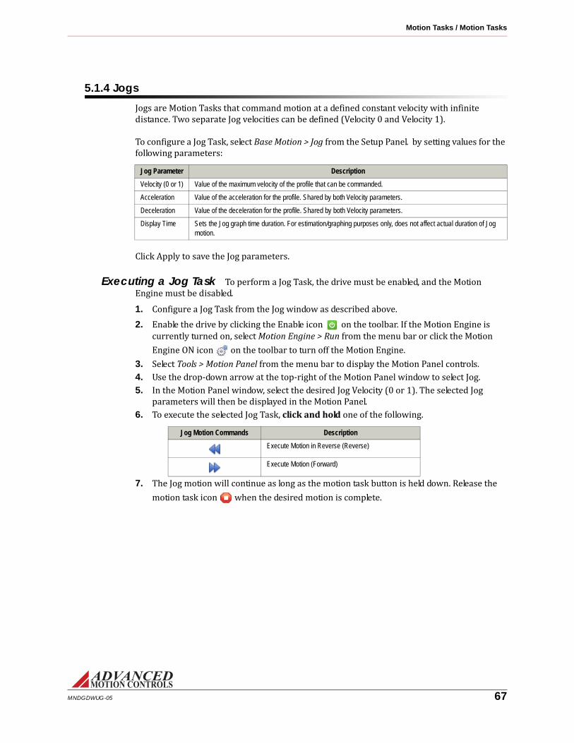
Motion Tasks / Motion Tasks
5.1.4 JogsJogs are Motion Tasks that command motion at a defined constant velocity with infinite distance. Two separate Jog velocities can be defined (Velocity 0 and Velocity 1). To configure a Jog Task, select Base Motion > Jog from the Setup Panel. by setting values for the following parameters:
Click Apply to save the Jog parameters.Executing a Jog Task To perform a Jog Task, the drive must be enabled, and the Motion Engine must be disabled.
1. Configure a Jog Task from the Jog window as described above.2. Enable the drive by clicking the Enable icon on the toolbar. If the Motion Engine is currently turned on, select Motion Engine > Run from the menu bar or click the Motion Engine ON icon on the toolbar to turn off the Motion Engine.3. Select Tools > Motion Panel from the menu bar to display the Motion Panel controls.4. Use the drop-down arrow at the top-right of the Motion Panel window to select Jog.5. In the Motion Panel window, select the desired Jog Velocity (0 or 1). The selected Jog parameters will then be displayed in the Motion Panel.6. To execute the selected Jog Task, click and hold one of the following.
Jog Motion Commands Description
Execute Motion in Reverse (Reverse)
Execute Motion (Forward)
7. The Jog motion will continue as long as the motion task button is held down. Release the motion task icon when the desired motion is complete.
Jog Parameter Description
Velocity (0 or 1) Value of the maximum velocity of the profile that can be commanded.
Acceleration Value of the acceleration for the profile. Shared by both Velocity parameters.
Deceleration Value of the deceleration for the profile. Shared by both Velocity parameters.
Display Time Sets the Jog graph time duration. For estimation/graphing purposes only, does not affect actual duration of Jog motion.
MNDGDWUG-05 67

6 Downloading the Firmware
Each time the manufacturer releases a new setup software version or issues a firmware patch, you should update the firmware on your existing digital drives. When you work closely with the manufacturer, particularly for custom products, firmware changes may be required several times throughout your development process.6.1 Prepare for Download
1. Connect to the drive.2. Open the Connection Settings window by going to Drive > Connect, and changing the connection setting to a high baud rate.3. Make sure the parameters are correct in both the setup software and the drive.4. Store parameters to the drive’s nonvolatile memory.
6.2 Open the Firmware Download WindowSelect Drive > Firmware Download on the menu bar to open the Firmware Download window.This window allows changes and upgrades to the drive run-time firmware. For example, you may need to upgrade when a new version of software is to be used with an older drive or when a new drive needs a previous version to work in a system.Check the Current Information window to view which firmware is currently in the drive. If the firmware file name matches the recommended name in the Select Firmware window, a firmware upgrade is unnecessary and you may click the cancel button. If the two names are different, you should update the firmware.Browse Folder/Browse File: If the drive firmware is not installed in the default directory, you may need to browse for it. Use these buttons to navigate to where the firmware file is located.
MNDGDWUG-05 68

Downloading the Firmware / Downloading the Firmware
6.3 Downloading the Firmware
1. Select the recommended firmware file.2. Click on the Download button.This process may take several minutes depending on your connection.3. The Close the dialog box when download completes box is checked by default so that you will return to the main workspace after firmware upgrade completes.4. If the ’Bridge State on Power-up’ option in the Power-up Control tab in Limits and Options is set to Enable, you will see a dialog window during the download asking if you would like to reset the drive after the firmware download is complete:Be aware that resetting the drive in this case will cause the power bridge to be enabled after the download is complete, unless there is a hardware limiting event active (invalid halls, digital inputs, etc). If you choose not to reset the drive, the bridge will be disabled upon download completion, and the drive will not go through its normal power-up sequence.5. When the upgrade is complete, store the parameters to nonvolatile memory.6. Read the release notes for information about new features and issues.
Do not power down or lose your connection during the process. If this happens, you may have to restart the download, or in extreme cases, send the drive back to the manufacturer.
MNDGDWUG-05 69

A Tools and Functions
This appendix describes helpful tools provided by the setup software.A.1 Digital OscilloscopeThe digital scope is a powerful tool used for tuning and diagnostics. You can select from more than forty different signals to monitor while testing or troubleshooting your machine. Slower baud rates can affect the scope performance.To open the digital oscilloscope, do one of the following:
• Select Tools > Scope/Tuning on the menu bar.• Click on the Scope/Tuning icon on the tool bar.• Select Control Loops > Scope/Tuning from the Setup Panel.The oscilloscope provides real-time feedback and adjustment during tuning and setup. This multichannel digital scope behaves similarly to a traditional oscilloscope but provides access to internal drive signals. You can show up to eight channels at any time depending on the bandwidth used for each channel. The units used in the vertical division setting depend on the selected signal.Standard prefixes such as μ (micro-), m (milli-), k (kilo-), M (mega-), are used for scaling factors. The bridge does not need to be enabled to use the scope. All that is required is that the drive be powered up and connected.
Channel Select The Channel Select section provides selection of oscilloscope signals.• Add Signal: Adds a new channel to the scope (if available) and allows you to select a corresponding signal of your choice. This button will be disabled (grey) if all oscilloscope channels are used.• Change: Changes the currently selected signal to another one of your choice.• Remove: Removes the selected channel from the scope.A list of available channels and their definitions can be found in the “Signal Definitions” on page 77.
MNDGDWUG-05 70

Tools and Functions / Digital Oscilloscope
Presets Automatically configured oscilloscope settings that are frequently used when tuning the drive. Each preset has pre-determined unit and time per division scaling. Click on the corresponding button to either load a preset or save the existing layout as a preset. The presets will be reset to the defaults when DriveWare is closed and re-opened.• Current: Configures the oscilloscope settings for monitoring a target current command and the measured drive output current.• Velocity: Configures the oscilloscope settings for monitoring a target velocity command and the measured motor velocity.• Position: Configures the oscilloscope settings for monitoring a target position command and the measured motor position.
Display The Display section provides configuration of the oscilloscope display settings.• Time/Div: Shows the horizontal scaling time per division for the corresponding signal as seen in the digital scope display.• Scale: Shows the units per division for the corresponding signal as seen in the digital scope display.• Offset: Shows the offset associated with the signal as seen in the digital scope display.• Horizontal Location: Allows adjustment of the horizontal (time-based) level at which the scope triggers.
Trigger The Trigger section provides configuration of the oscilloscope settings.• Source: Displays the currently selected signal to be used as a trigger.• Level: Allows you to select the level at which you want the scope to trigger.• Slope: Sets the trigger slope to positive slope or negative slope.• Mode: Sets the trigger mode to one of the following:
— Normal Mode: The scope triggers according to the settings specified.— Single: The scope triggers once, according to the settings specified, after Run/Stop button is selected.— Auto: The scope triggers automatically, ignoring the settings specified.— Roll: The scope triggers in a continuous roll. Note: you will be limited to 200 msec/Div minimum while in roll mode.
Measure The Measure section provides real-time measurement between any two signals displayed on the oscilloscope.• Time: This allows you to measure time differences between any two points on the scope display. Click the Time checkbox to display two vertical lines on the scope plot. The difference in time between the two lines is displayed in the box to the right of the check box. Left click to drag each line or right click to drag both.• Signal Level: Select a channel for measurement from one of the two dropdown boxes. You may use either of the two dropdown menus to select a channel. The difference between the lines is displayed next to the channel selection dropdown; the selected channels units apply. Depending on whether the Time checkbox is selected, the values measured will either be horizontal time/div or vertical units/div. Left click to drag each line or right click to drag both.
MNDGDWUG-05 71

Tools and Functions / Digital Oscilloscope
A.1.1 Waveform GeneratorThe Waveform Generator is used to generate an internal signal during drive tuning and other procedures, eliminating the need for external signal sources during tuning. To open the Waveform Generator, open the Scope/Tuning window, then click on the Waveform tab.• Enabled: The Enabled checkbox enables/disables the Waveform Generator. This checkbox is unchecked by default. When checked, the Waveform Generator will override any previously configured command source. Upon disabling the checkbox, the command source will return to the previous setting.• Type: Select a DC (constant), square wave, triangle wave, or sinusoidal waveform.• Target: Select the destination for the waveform signal. Not Connected means the waveform signal will not be used. Command Limiter means the command signal will be limited as defined in the Command Limiter section of the active Configuration.• Frequency: Select the frequency of the waveform signal. This becomes inactive when "DC" is selected for the waveform type.• Amplitude: Corresponds to the amplitude of the waveform signal (equivalent to half of the peak-to-peak value). Disabled in the case where a DC waveform is selected. Clicking on the button will set the amplitude to zero.• Offset: Adds an offset to the selected waveform. If a DC waveform is selected, the offset corresponds to the DC signal amplitude.
— When the Position Loop is enabled, the button will set the offset equal to the measured position.• Symmetry: Corresponds to the duty cycle or symmetry of the waveform signal. This becomes inactive when DC is selected for the waveform type.
MNDGDWUG-05 72

Tools and Functions / Multimeter
A.2 MultimeterThe Multimeter allows you to monitor a multitude of signal types including positions, velocities, torques, and voltages. In addition, a resettable counter keeps track of the minimum and maximum values found. Scaling is selected in the option select field on the right side, or you may choose Auto Scaling to automatically scale the units for you.You must be connected to a drive to use the multimeter.To open the multimeter, do one of the following:• Select Tools > Multimeter on the menu bar.• Click on the multimeter icon on the tool bar.To see a list of available signals for the multimeter, see “Signal Definitions” on page 77.
The multimeter samples signals at a rate of once every 250 ms or four times per second. If you want to measure a faster signal, use the Digital Scope.
Note
MNDGDWUG-05 73

Tools and Functions / User Units
A.3 User UnitsThe User Units window allows the specification of the general units to be used throughout the application. A variety of units are selectable. The User Units window also allows the defintion of custom units.The User Units window is found under Settings > User Units in the menu bar or by clicking on the User Units icon in the toolbar.• Select the type of unit to be used for each data type (Position, Velocity, Acceleration, etc.) from the drop-down menus.• Selecting the Custom Labels checkbox will allow the definition of custom units and labels. A scaling ratio between standard and custom units can also be defined.• If an Auxiliary Encoder is selected as auxiliary feedback in the Aux Encoder Input window, then the Auxiliary Units tab will be available for configuration. This allows auxiliary units to be set when using dual-loop feedback. Custom units can also be defined for auxiliary units.
MNDGDWUG-05 74

Tools and Functions / Motion Panel
A.4 Motion PanelThe Motion Panel controls are opened by selecting Tools > Motion Panel from the menu bar. The Motion Panel is used to select and execute motion tasks that have been pre-defined in the Home, Jog, and Indexes windows, or to define parameters for a single index task with the Dynamic Index tool. The Motion Panel is also used to execute PVT commands.The Motion Panel provides a set of control buttons for various motion functions. Note that Jogs only allow forward or reverse motion, and cannot be set for automatic looping.
Indexes For more information on Indexes, see “Indexes” on page 63.• Selects a pre-defined Index task (Index00 - Index15). Only Indexes that have already been defined in the corresponding Index window will be available for selection.• The Index parameters will be displayed in the Motion Panel window.• The available Motion Panel Index controls will depend on the type of index selected (Absolute or Relative).
Dynamic Index For more information on Dynamic Indexes, see “Indexes” on page 63.• Configure parameters for a single index task within the Motion Panel window.• Both Absolute and Relative Index tasks can be defined with the Dynamic Index tool.
Jog For more information on Jogs, see “Jogs” on page 67.• Selects a pre-defined Jog task (0 or 1).• The corresponding Jog velocity, accel, and decel will be displayed in the Motion Panel window.• The Motion Engine does not need to be enabled to execute Jog tasks.
PVT For more information on PVT and how to construct a PVT points file, see “PVT” on page 65.• Used to execute PVT commands from a PVT points file. Note that the Motion Engine must be turned off to use the PVT generator.• A PVT file can be constructed using Notepad or a similar text editor program. Each line in the file represents a PVT point by specifying position, velocity, and time separated by semi-colons.
Icon Description
Execute the Home Method (home)
Halt Motion (halt)
Repeatedly Execute Motion in Reverse (loop reverse)
Execute Motion in Reverse (reverse)
Execute Motion (forward)
Repeatedly Execute Motion (forward loop)
Loop over Forward and Reverse Motion (cycle motion)
MNDGDWUG-05 75

Tools and Functions / Motion Panel
• Before running a PVT file, it is recommended to connect at the highest baud rate available, and to minimize the number of applications running in the background. Also close any unnecessary windows in DriveWare as they will slow down the rate at which the drive receives PVT points, possibly resulting in a PVT buffer error.Motion Status
• Displays the real-time measured values for Position, Velocity, Torque (% of continuous current limit as defined in the Current Limits window), and position error.• The Motion Status panel also displays the current state of the Motion Engine (Disabled, Ready, Halting, etc.).
MNDGDWUG-05 76

Tools and Functions / Signal Definitions
A.5 Signal DefinitionsThe following tables show all of the signals that can be measured using the Oscilloscope and Multimeter. These signals may also be used as analog outputs in compatible drives.Current measurements
For Iq and Id, “I” represents the peak of the current sin wave for an individual phase in a three phase motor.
Depending on the drive type, motor type, and motor settings, some of the signals may not be available.
Velocity measurements
Value Definition
Current Target (Iq) This is the commanded torque-producing current. Current limit settings are ignored.
Current Demand (Iq) The commanded torque-producing current, after current limits have been applied. This value is zero when the drive is inhibited.
Current Measured (Iq) The actual measured torque-producing current being delivered to the motor. Ideally, this value should be as close as possible to the demand current.
Id - Target This represents the flux producing stator current in an AC induction motor. Id should equal zero when using a permanent magnet motor.
Id - Demand This represents the flux producing stator current in an AC induction motor. Id should equal zero when using a permanent magnet motor.
Id - Measured This represents the flux producing stator current in an AC induction motor. Id should equal zero when using a permanent magnet motor.
Current Phase A The measured current in motor phase A. The sum of all three phases should add up to zero.
Current Phase B The measured current in motor phase B. The sum of all three phases should add up to zero.
Flux Ref. Current Target The commanded flux reference current ignoring limits. The flux reference current is the current induced in the rotor of an AC induction motor.
Flux Ref. Current Demand The commanded flux reference current, after limits have been applied. The flux reference current is the current induced in the rotor of an AC induction motor.
Flux Ref. Current Measured The measured flux reference current. The flux reference current is the current induced in the rotor of an AC induction motor.
Flux Ref. Current Error The difference between the flux reference current target and the flux reference current measured.
Current Pre-Filtered Target This is the commanded torque-producing current before current loop input filtering or current offset.
Value Definition
Velocity Target This is the commanded velocity ignoring velocity limit settings.
Velocity Demand The commanded velocity, after velocity limits have been applied. This value is zero when the drive is inhibited.
Velocity Measured The velocity as measured by the velocity feedback device (after filtering).
Velocity Feedback The velocity as measured by the velocity feedback device (before filtering).
Velocity Error The difference between the motor's target velocity and measured velocity.
Velocity Pre-Filtered Target This is the commanded velocity before velocity loop input filtering or velocity offset.
MNDGDWUG-05 77

Tools and Functions / Signal Definitions
Position measurements
Commutation
Voltage
Command Limiter
Value Definition
Position Target This is the commanded position ignoring position limit settings.
Position Demand The commanded position, after position limits have been applied.
Position Measured The position as measured by the position feedback device.
Primary Feedback Position This signal is used by the drive for commutation purposes, and may differ from the measured position. For determining measured position, reference the Position Measured signal.
Auxiliary Feedback Position The position as measured by the auxiliary feedback port. Only valid when Auxiliary Encoder is configured as a feedback device.
Position Error The difference between the motor's target position and measured position.
Position Pre-Filtered Target This is the commanded position before position loop input filtering.
Value Definition
Sync Error Synchronization is used with brushless motors to verify the commutation angle is valid for the measured position. When synchronization occurs, the drive compares the expected position to the measured position. If the two are not aligned, the drive cannot reliably commutate and a synchronization error results.
Hall State The decimal equivalent of the binary combination of the three hall states where Hall A is bit 0 and Hall C is bit 2. (5V = 1, 0V = 0). It is important to note that the binary value is inverted for PCB drive models. For example, a standalone drive may read a Hall State of 1-1-1, while a PCB-mounted drive would read a Hall State of 0-0-0 in the same situation.
Phase Angle The present number of degrees of the rotor inside one electrical cycle. Also may be called Electrical Angle.
Sync. Capture The encoder count captured at the Synchronization edge. This will vary depending on the Sync edge chosen from AutoCommutation (Hall or Index edge).
Stator Angle The present number of degrees of the stator inside one electrical cycle. This value is equal to the phase angle plus the slip angle.
Value Definition
Analog Output The present voltage applied to the analog output.
DC Bus Voltage The voltage the drive can output during the ON state of a PWM cycle. This is generally equivalent to the DC or rectified AC supply voltage to the drive. The DC Bus Voltage may be greater than the supply voltage when the motor is in a state of regeneration.
Voltage Phase A The voltage, with respect to DC bus ground, applied to motor phase A
Voltage Phase B The voltage, with respect to DC bus ground, applied to motor phase B.
Voltage Phase C The voltage, with respect to DC bus ground, applied to motor phase C.
Analog Input The voltage measured on the analog input pin with respect to signal ground.
Value Definition
Command Limiter Input The commanded signal before being profiled by the command limiter.
MNDGDWUG-05 78

Tools and Functions / Signal Definitions
Temperature
Torque
Drive
Commanded Input value
Deadband Input
PWM Input
Value Definition
Motor Temp. The calculated motor temperature after being measured on the selected input and scaled according to the specified scaling value.
Value Definition
Torque Measured The torque applied by the motor. This value is calculated from measured current, as delivered to the motor from the drive, and the motor torque constant entered in the Motor Data window.
Value Definition
Drive Position The position as measured by the drive in counts.
Drive Velocity The velocity as measured by the drive in counts per second.
Value Definition
Commanded Input The decimal value read from the interface input.
Value Definition
Deadband Input The commanded input before deadband is utilized. Measured in units of current, velocity, or position depending on configuration.
Value Definition
PWM Duty Cycle This represents the duty cycle of the input when the drive is configured for PWM as a command.
MNDGDWUG-05 79

Tools and Functions / Drive Status
A.6 Drive StatusThe Drive Status pane shows drive events (current and history) and is a useful troubleshooting diagnostics tool. Click on the Drive Status tab in the Setup Panel to view the Drive Status information.The Drive Status pane shows data in three categories:• Drive protection• System protection• System StatusFor a description of drive events and recommended troubleshooting methods, see “Events and I/O Descriptions and Troubleshooting Methods” on page 102.Use the icons at the top of the pane to select viewing options.
Event States
Icon Name Description
Expand All Show all sub-categories.
Collapse All Hide all sub-categories.
Reset Events Clear the Drive Status window of any history events.
Show Inactive Show or hide the inactive status events.
Show History Show or hide the status history events.
Icon Name Description
Active An event that is active but not assigned to an action. This includes events assigned to No Action in the Event Manager window and pure status events that cannot be assigned an action.
Disabling Event An event that is active and assigned to an action. An action either inhibits motion partially or disables motion completely according to the action assigned in the Event Manager window.
History An event which is not presently active, but was active at some point after the last time the drive was powered on or the last time the Reset Events button was used.
Inactive An event that is not presently active, and has not been active since after the last time the drive was powered on or the last time the Reset Events button was used.
MNDGDWUG-05 80

Tools and Functions / Critical Event Activity
A.7 Critical Event ActivityThe Critical Event Activity window is a list of drive protection events along with the time they occurred. The critical event activity window contains entries such as Short Circuit and Current Overshoot.Click on the Critical Event Activity tab to view the Critical Event Activity information.
A.8 Event CountersLists the total operating time of the drive and the number of times faults have occurred since the drive has been in operation.Click on the Event Counters tab to view the Event Counters information.
Icon Name Description
Refresh Refresh the Event Activity log.
Export Export the Event Activity log to a text file.
Icon Name Description
Refresh Refresh theEvent Counter values.
Export Export the Event Counter values to a text file.
Event Counters automatically stores to the drive approximately once every nine minutes. If the drive power is shut off within this time frame and a manual store to NVM is not performed, the counter will not be incremented.
Note
MNDGDWUG-05 81

B Current Limiting
This topic explains current limiting for digital servo drives. The basic concepts of current limiting are introduced first, followed by a detailed explanation of some underlying formulas.B.1 Understanding the Limit EnvelopeDigital drives limit current output according to a well-defined software and hardware current limit envelope. These envelopes consist of Peak Current, for a specified amount of Peak Current Time, followed by a foldback to Continuous Current for an amount of time specified by the Foldback Time Constant.
Foldback & current limit envelope1. The current limit envelope is shown in red.
2. You use drive setup software to configure the software envelope while the hardware envelope is fixed and defined by drive hardware limitations.
3. The Peak Current Time and Foldback Time Constant of the hardware envelope is the same for all drives, fixed at 2 and 10 seconds, respectively. The current values, how-ever, depend upon the hardware with Peak Current and Continuous Current always equal to the maximum peak and continuous current rating of the drive.
MNDGDWUG-05 82

Current Limiting / Understanding the Limit Envelope
The drive always compares each point on the user specified software envelope against each point on the hardware envelope and takes the lesser of the two to generate the actual application envelope. An example of this, where the hardware envelope almost entirely overrides the software envelope, is shown in Table 1. In this example, a constant 100% peak current command (shown in white) was given to the drive. Because, beyond the first two seconds, the hardware envelope (2 seconds Peak Current Time and 10 second Foldback Time Constant) is less demanding than the software specified envelope (65 second Peak Current Time and 65 second Foldback Time Constant), hardware current limiting is applied.
Table 1
MNDGDWUG-05 83

Current Limiting / Understanding the Limit Envelope
In order to have the software envelope entirely hold true, it must be specified such that it remains equal to or within the hardware envelope of the drive. Table 2 shows an example of a software configuration that will hold true in application (i.e. not be overridden by hardware limitations). For convenience, the drive hardware envelope has been superimposed (in red) on the image of Table 2.
Table 2
MNDGDWUG-05 84

Current Limiting / Understanding the Limit Envelope
On the other hand, Table 3 shows the result of a user configured software envelope that falls outside of the allowed hardware envelope. The image in Table 3 shows how the drive will follow the specified software envelope up until it intersects the hardware envelope.
Table 3
MNDGDWUG-05 85

Current Limiting / Current Limiting Algorithm
FIGURE B.1 Current Limiting Regions
Ip
Ic
Continuous Region
Foldback Region
Peak Time Foldback Time
Time
Peak Region
Current
B.2 Current Limiting AlgorithmIn order to understand the current limiting algorithm used by digital servo drives, it is necessary to first understand the different current limiting regions. The graph in Figure B.1 breaks the available current into three different regions.
• Continuous Region: The commanded current is less than or equal to the continuous current limit. The available current is equal to the commanded current.• Peak Region: The commanded current is between the continuous and peak current limits. The available current is equal to the commanded current for a limited time (Peak Time).• Foldback Region: Commanded current is between the continuous and peak current limits of the drive. The available current is less than the commanded current. The available current decreases over time until it equals the continuous current limit. The rate of this decrease is equal to:
Slope Ip Ic–tf
-----------------=
Ip Peak current limitIc Continuous current limittf Foldback time
MNDGDWUG-05 86

Current Limiting / Current Limiting Algorithm
FIGURE B.2 Time-Based Peak Current Limiting
Ip
Ic
Current-Time
Tp
Icommanded
Iavailable
tf
B.2.1 Time-Based Peak Current LimitingThe full peak value of current is available to begin with. When a current command is equal to the peak current limit, the current begins to foldback to the continuous limit after Tp, following the same slope as given in Figure B.1 on page 86. Once the available current has reached the continuous current limit after tf, the available current will be limited to the continuous current limit until the commanded current is dropped below the continuous level.
MNDGDWUG-05 87

Current Limiting / Current Limiting Algorithm
FIGURE B.3 Time-Based Non-Peak Current Limiting
Ip
Ic
Current-Time
Icommanded
Iavailable
Tp
tf
B.2.2 Time-Based Non-Peak Current LimitingWhen the commanded current is between the peak and continuous current limits, the available current will begin to foldback at the intersection with the slope from Figure B.2 on page 87. The larger the commanded current, the sooner the available current will begin to foldback.
MNDGDWUG-05 88

Current Limiting / Current Limiting Algorithm
FIGURE B.4
Ip
Ic
Iavailable
Zero Current
t
t = A1
2(Ip – Ic)
A2
Ip
Ic
Current-Time
Tp
tf
Icommanded
Iavailable
Zero Current
Foldback
A1
Time-Based Current Recovery - Foldback and Commanded Current
B.2.3 Time-Based Current RecoveryInitially, the full peak value of current is available. A commanded current above the continuous level causes the available current to foldback to the continuous level as shown in the first graph of Figure B.4. When the commanded current drops below the continuous current limit value (A1 in the first graph), the available current will then begin to recover along the slope of the foldback line towards the peak current level, as shown in the second graph of Figure B.4. The relationship between the commanded current and the recovered current is given as: A2
12---A1=
Using this relationship, you can calculate the amount of time recovered, Δt, by using the following equation:
Note that current must be commanded below the specified continuous value to start recovering from a foldback condition.
ΔtA1
2 Ip Ic–( )-----------------------=
MNDGDWUG-05 89

Current Limiting / Current Limiting Algorithm
FIGURE B.5 Charge-Based Peak Current Limiting
Ip
Ic
Full Charge
Zero Charge
Current-Time
Charge-Time
B.2.4 Charge-Based Peak Current LimitingThe charge is full to begin with. When a current greater than the continuous current limit is commanded, the charge begins to decay. The loss of charge is determined by the area under the curve as shown in Figure B.5. The larger the command, the faster the charge will decay. When the charge decreases to zero, the available current will be limited to the continuous current limit until the charge is restored.
MNDGDWUG-05 90

Current Limiting / Current Limiting Algorithm
FIGURE B.6 Charge-Based Non-Peak Current Limiting
Ip
Ic
Full Charge
Zero Charge
Current-Time
Charge-Time
Icommanded
Slope during foldback
B.2.5 Charge-Based Non-Peak Current LimitingWhen the commanded current is between the peak and continuous current limits, the commanded current will be available for a longer period when compared to limiting at peak command. Note that the slope of the line during foldback is the same for both cases.
MNDGDWUG-05 91

Current Limiting / Current Limiting Algorithm
FIGURE B.7 Charge Recovery
Ip
Ic
Full Charge
Zero Charge
Current-Time
Charge-Time
Commanded Current
Foldback Foldback
Charge Recovery
0
B.2.6 Charge-Based Current RecoveryAfter losing some value of charge, the charge may be recovered when the commanded value is dropped less than the continuous current limit. The amount of charge recovered depends on the magnitude of the commanded current and the amount of time in which it is commanded. The amount of charge recovered can be calculated by measuring the area within the curve as shown during the charge recovery phase in Figure B.7.
MNDGDWUG-05 92

Current Limiting / Current Limiting Algorithm
FIGURE B.8 RMS Current Limiting
Ip
Icdc
RMS Current Scaling
Icrms
Electrical cycle frequency Above RMS cutoff frequeny
Electrical Cycle Frequency below DC cutoff frequency
Tp Time
Current
B.2.7 RMS Current ScalingRMS Current Scaling uses the charge-based algorithm described above. The only difference is the value of the continuous current the drive is capable of outputting. The continuous RMS limit can be used when the motor is moving so that the electrical cycle frequency is greater than the upper frequency assigned to that drive. The upper frequency is typically around 5Hz or 150 RPM for a 4-pole motor. The continuous RMS value is the continuous DC value multiplied by the square root of two.Icrms 2 Icdc⋅≡
When the electrical cycle frequency drops below the upper frequency, the continuous current drops below the RMS value. When the motor is moving at slow speeds, the continuous current is equal to the DC value of the current.
MNDGDWUG-05 93

Current Limiting / Calculating Current Limits
B.3 Calculating Current LimitsAvailability of output current greater than continuous current depends on the level of an internal charge reservoir. Upon power-up, the drive begins with a full reservoir having a charge equal to:QP = Peak Reservoir ChargeIP = Peak CurrentIC = Continuous CurrenttP = Peak Current TimetF = Foldback Time ConstantA drive with a fully charged reservoir can always output peak current. However, any time the target output current goes above the Continuous Current setting of the drive the reservoir begins to discharge. The rate of discharge is given as:For IT > IC,IT = Target Current (units of amps)C = coulombss = secondsOnce the reservoir discharges past a threshold necessary to output peak current, the amount of current available to output begins to foldback linearly (assuming hardware limits do not override software limits) from IP to IC according to the Foldback Time Constant (tF).When the reservoir becomes empty, no more than Continuous Current can be output by the drive. The peak current threshold can be calculated as:
which is simply the amount of charge that would be depleted over a complete current foldback. The reservoir recharges (up to a maximum of QP) anytime the target output current drops below the Continuous Current setting. The rate of charge depends upon how far the target output current is below the Continuous Current as given by:For IT < IC,As a result, the reservoir will recharge most rapidly when the target output current is zero (no command or drive inhibited).
QP 2 IP IC–( ) tP tF+( )=
2 IP IC–( )C s⁄
QTh QP tF×( ) tP tF+( )⁄=
IC IT–( )C s⁄
MNDGDWUG-05 94

Current Limiting / Calculating Current Limits
B.3.1 Example 1: Foldback CurrentWhat is the output current of a drive enabled in the foldback state (0 < Q < QTh) if the drive is configured according to the parameters in “Table 2” on page 84? Assume that the charge reservoir has been tracked since power-up and is known to be half empty (Q = QP/2) at the instant it is enabled. Because current limits are set within hardware limits the current foldback will be linear and easily represented by the first order equation:For 0 < t < tx,IF = the foldback currentM = the rate of foldbackt = is time (drive enabled at t=0)I0 = the initial current outputStarting with I0, the initial amount of current available beyond continuous current will be the maximum difference between peak and continuous current (IP - IC) weighed against the percentage of charge Q available relative to QTh. Using IC as a baseline, this is formulated as,For 0 < Q < QTh,
Taking the drive parameters of Table 2, I0 is calculated as follows.I0 = (IP - IC) × [QP/2]/[(QP × tF)/(tP + tF)] + IC= (IP - IC) × (tP + tF)/2tF + IC= (12 - 6) × (2 + 5)/10 + 6= 10.2 A.The rate of foldback can be formulated asAgain using the parameters of Table 2, this gives M = (6 - 12)/5 = -1.2. Lastly, we need to calculate the time at which foldback ends. Knowing that foldback always ends with IC, we can use the line equation we just generated to calculate tx by solving for time as follows:tx = (IF - I0)/M= (6 - 10.2)/-1.2= 3.5Combining all our results, this yields the formula:For 0 < t < 3.5,IF = -1.2t + 10.2.
IF Mt Io+=
I0 IP IC–( )Q QTh⁄ Ic+=
M IC IP–( ) tF( )⁄=
MNDGDWUG-05 95

Current Limiting / Calculating Current Limits
B.3.2 Example 2: Peak Current RecoveryIf recovery time is the only interest, there's an easy way to calculate the amount of time required to recover maximum peak current. This is shown in the following example.How long will it take to recover maximum peak current on a drive which, from power-up, is depleted for tD seconds, where tD < tP + tF?Assume the current command is initially held at a constant current of IH, where IH > IC, for tD seconds and then held constant at IL, where IL < IC, for tR seconds. These parameters are illustrated as:
Depletion of the reservoir always happens at the rate 2(IP - IC) which means the amount of charge depleted over tD will be QD = 2(IP - IC) x tD. Similarly, for a recharge time of tR, the charge recovered will be QR = (IC - IL) x tR. In order to fully recharge the reservoir, the amount of charge depleted must match the amount recovered such that QR = QD or (IC - IL)tR = 2(IP - IC)tD. The final step is to solve for tR as shown below.The concept of peak current recovery can be approached a little differently by matching the area of two squares. This method tends to be more intuitive and is easy to visualize. The previous figure illustrates a typical current limiting envelope (in red) with an example current command (in green) and two square areas marked AD and AR. Note that the area of AD is equal to (IP - IC) × tD while the area of AR is equal to (IC - IL) × tR. Now, from Example 2, we know that the charge recovered should match the charge depleted. Given this, we can equate areas as given below:QR = QD(IC - IL)tR = 2(IP - IC)tDAR = 2ADThus, in order to completely recover peak current, the area of the square (IC - IL) × tR must double the area of the square (IP - IC) × tD.
tR 2 IP IC–( )tD IC IL–( )⁄=
MNDGDWUG-05 96

C Control Loop Architecture
The following diagram shows how the various PID and feed-forward terms are implemented in the control loop for Position around Velocity around Current (Torque) tuning. Other drive configurations are possible as well.Biquad
Position Measured
Velocity Measured
Command Source
Velocity Control Algorithm
Current Control Algorithm
Source Modifier
Position Control Algorithm
Motor and
Feedback
Load and Aux Feedback
Loop Feedback Selection
Velocity FeedbackFirst Order Low
Pass Filter
fc
Biquad Low Speed Smoothing
(EE/RE only)
Biquad
Position Target
Position Demand Position
Error
-
++
+
Kaffd2
dt2
Kvffddt
Kpp
Kip?dt
Kdpddt
Position Integrator
Decay
Position Limits
Biquad
Position Pre-FilteredReference
+
Position Measured
Position Control Algorithm
+
Position Offset
Position Reference
Velocity Target
Velocity Demand
Velocity Error
+
-
++
+
dt
Kpv
Kiv?dt
Kdvddt
Kaffd
Velocity Integrator
Decay
+
Velocity Offset
Velocity Pre-FilteredReference
Velocity Measured
Velocity Control Algorithm
Velocity Limits
Biquad
Velocity Reference
Limits
Current Target
Current Demand
+
-
++
Kpi
Kii?dt+
Current Offset
Current Pre-FilteredReference
Current Control Algorithm
Biquad
Current Reference
MNDGDWUG-05 97
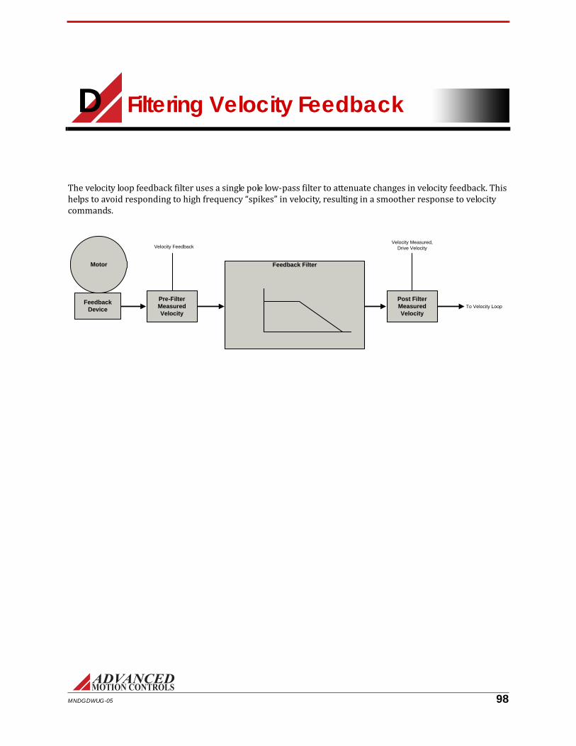
D Filtering Velocity Feedback
The velocity loop feedback filter uses a single pole low-pass filter to attenuate changes in velocity feedback. This helps to avoid responding to high frequency “spikes” in velocity, resulting in a smoother response to velocity commands.
Feedback Device
Motor
Velocity Feedback
Pre-Filter Measured Velocity
Feedback Filter
Post Filter Measured Velocity
To Velocity Loop
Velocity Measured,Drive Velocity
MNDGDWUG-05 98

Filtering Velocity Feedback / Effects of the Feedback Filter
D.1 Effects of the Feedback FilterThe figures below show how the filter affects measured velocity and, in turn, motor response. For this example, a 10Hz, 100,000-count/sec sine wave is commanded by the drive. This will be considered the worst-case move required for the application. The motor uses a 2000 line encoder, and has a low inertia load coupled to the motor shaft. The current loop and velocity loop gains are tuned aggressively for a fast response.D.1.1 Cutoff Frequency Set to Infinite
With no feedback filter, the velocity measured and velocity feedback are equal. The velocity loop responds instantly to all measured changes in velocity. The resulting velocity profile is distorted. A loud audible noise is heard from the motor.D.1.2 Cutoff Frequency Set to 300Hz
At this level, the audible noise is no longer present and the response is smooth. The two waveforms are nearly identical. This is the optimum setting because it results in no distortion and no phase lag.
MNDGDWUG-05 99

Filtering Velocity Feedback / Conclusion
D.1.3 Cutoff Frequency Set to 50Hz
At this level, the response is still smooth, but phase lag is apparent as the two waveforms begin to separate.D.1.4 Cutoff Frequency Set to 10Hz
With the cutoff frequency set to 10Hz, there is an obvious difference between the two waveforms. The response is also noticeable in the motor shaft. The phase lag results in the motor motion becoming unstable.D.2 ConclusionThe velocity loop cutoff frequency filter allows you to tune with higher velocity loop gains, which results in a faster response. Most applications will benefit from a velocity feedback filter cutoff frequency between 50Hz and 1500Hz. Too high of a cutoff frequency may result in audible noise from the motor. Too low of a cutoff frequency will cause significant phase lag and may lead to instability. The cutoff frequency should be adjusted during velocity loop tuning. For the worst-case move, the motor should follow the command smoothly, and there should be little or no phase lag between the velocity feedback and velocity measured traces.
MNDGDWUG-05 100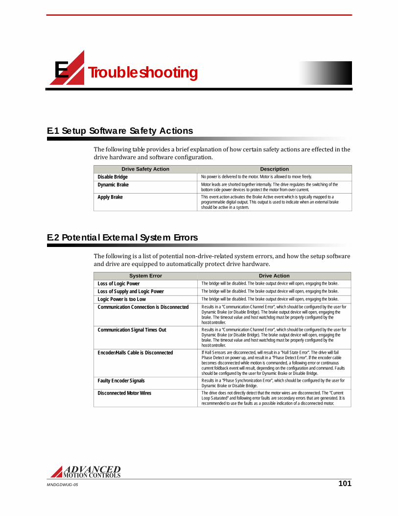
E Troubleshooting
E.1 Setup Software Safety ActionsThe following table provides a brief explanation of how certain safety actions are effected in the drive hardware and software configuration.Drive Safety Action Description
Disable Bridge No power is delivered to the motor. Motor is allowed to move freely.
Dynamic Brake Motor leads are shorted together internally. The drive regulates the switching of the bottom side power devices to protect the motor from over current.
Apply Brake This event action activates the Brake Active event which is typically mapped to a programmable digital output. This output is used to indicate when an external brake should be active in a system.
E.2 Potential External System ErrorsThe following is a list of potential non-drive-related system errors, and how the setup software and drive are equipped to automatically protect drive hardware.System Error Drive Action
Loss of Logic Power The bridge will be disabled. The brake output device will open, engaging the brake.
Loss of Supply and Logic Power The bridge will be disabled. The brake output device will open, engaging the brake.
Logic Power is too Low The bridge will be disabled. The brake output device will open, engaging the brake.
Communication Connection is Disconnected Results in a "Communication Channel Error", which should be configured by the user for Dynamic Brake (or Disable Bridge). The brake output device will open, engaging the brake. The timeout value and host watchdog must be properly configured by the host/controller.
Communication Signal Times Out Results in a "Communication Channel Error", which should be configured by the user for Dynamic Brake (or Disable Bridge). The brake output device will open, engaging the brake. The timeout value and host watchdog must be properly configured by the host/controller.
Encoder/Halls Cable is Disconnected If Hall Sensors are disconnected, will result in a "Hall State Error". The drive will fail Phase Detect on power up, and result in a "Phase Detect Error". If the encoder cable becomes disconnected while motion is commanded, a following error or continuous current foldback event will result, depending on the configuration and command. Faults should be configured by the user for Dynamic Brake or Disable Bridge.
Faulty Encoder Signals Results in a "Phase Synchronization Error", which should be configured by the user for Dynamic Brake or Disable Bridge.
Disconnected Motor Wires The drive does not directly detect that the motor wires are disconnected. The "Current Loop Saturated" and following error faults are secondary errors that are generated. It is recommended to use the faults as a possible indication of a disconnected motor.
MNDGDWUG-05 101

/ Events and I/O Descriptions and Troubleshooting Methods
E.3 Events and I/O Descriptions and Troubleshooting MethodsThe following is a list of possible drive events and I/O signals, a brief description of the cause, issue, or behavior, and some recommended actions to take to remove the event if necessary.Event Description Likely Cause Recommended Actions
Absolute Position Valid An absolute motor position has been established by one of the drive’s positioning methods.
1) A homing routine has been initiated and completed successfully
2) An absolute position has been established by execution of the Set Position command
3) Phase Detect routine has completed successfully (only applies to drives with absolute feedback devices)
Status Only, no action needed.
At Command Velocity Mode: The measured velocity has reached the target velocity, within the At Velocity Window.
Position Mode: The measured position has reached the target position, within the In-Position Window.
Note: At Command is not available in Torque Mode.
The drive has reached the commanded position within the range of the At Command window.
Status Only, no action needed.
Brake Active A drive event may be configured to activate an external brake. This is accomplished by assigning the event action and by assigning a digital output to "Apply Brake".
The drive’s Apply Brake action is enabled. If assigned to a digital output, the digital output will be active also. This occurs when an active event has its action assigned to Apply Brake.
Note: SynqNet drives control the brake through the SynqNet interface.
Check all active events. Check the settings for the event actions to see which event actions are assigned to Apply Brake.
Bridge Active The drive’s power bridge is enabled. The drive has been enabled. Status Only, no action needed.
Capture Complete The Capture routine has completed. The High Speed Capture function has been initiated and completed successfully.
Status Only, no action needed.
Command Limiter Active The command is currently being profiled by the Command Limiter.
The Command Limiter has been enabled. Status Only, no action needed.
Communication Channel Error The drive has experienced an interruption of communication on the communications interface. Note: Normal setup software communication interruption/loss will not trigger this error.
RS485/232:
If the drive is configured via index 0x04 for heartbeat this error will be thrown if the consumer heartbeat time is not reset within the defined time interval.
CANopen:
If the drive is configured for node / life guarding, the event will be thrown if the drive does not receive a node guard pulse within the specified time interval.
If configured for heartbeat, the drive will throw the error if the host fails to reset the timer within the specified time interval.
EtherCAT:
The EtherCAT RPDO watchdog has been activated. This occurs when EtherCAT state machine is operational and the drive has not received an RPDO in more than 10 cycles.
If configured for heartbeat, the drive will throw the error if the host fails to reset the timer within the specified time interval.
1) Communication cable has been disconnected
2) Host software has not been properly initialized
1) Check communication cable connections
2) Check to ensure host software is properly initialized.
Configuration Select The active drive Configuration has switched. A digital input has been configured to switch drive Configurations.
Status Only, no action needed.
Continuous Current Foldback The drive has been commanded to output greater than continuous current and has folded back to the continuous value. The peak and continuous currents will be either the software or hardware limits. When this event is active, the drive is supplying continuous current.
The drive current has folded back to the continuous value.
This is application dependent. Default event action is 'no action' which is informational only. Can be configured to perform an event action (i.e. disable bridge).
Current Limit Active The drive is applying current limiting based on the software settings specified, or is limiting according to the hardware limits of the drive.
The drive is being commanded to output current that exceeds software or hardware limits.
This is application dependent. Default event action is 'no action' which is informational only. Can be configured to perform an event action (i.e. disable bridge).
Current Loop Saturated The PWM output is at maximum duty cycle, and cannot deliver any more current under the given conditions.
1) The bus voltage is insufficient for a given motor / current level
2) The motor's resistance is high
3)The motor leads are not properly connected
1) Make sure there is sufficient bus voltage
2) Make sure motor resistance is not high
3) Turn the power off and make sure the motor leads are properly connected.
MNDGDWUG-05 102

/ Events and I/O Descriptions and Troubleshooting Methods
Drive Internal Error The drive has experienced an internal error while executing its firmware.
Defective drive Contact technical support
Drive Over Temperature The drive has reached its maximum allowed temperature. The drive will disable when this occurs, and will be re-enabled when sufficiently cooled.
1) Inadequate heatsinking / ventilation
2) Excessive and repeated overcurrents
1) Ensure adequate heatsinking / ventilation
2) Ensure that motor exceeds minimum inductance requirements
Drive Reset The drive's internal processor was reset. NOTE: This event will occur every time the drive is power cycled.
1) The drive was power cycled
2) A glitch in power caused a processor reset
1) None if the drive was power cycled (status only)
2) Check logic power coming to drive.
Dynamic Brake Active A drive event may be configured to activate the dynamic brake. This is accomplished by assigning the event action and by assigning a digital output to "Dynamic Brake".
The drive’s Dynamic Brake action is enabled. If assigned to a digital output, the digital output will be active also. This occurs when an active event has its action assigned to Dynamic Brake.
Check all active events. Check the settings for the event actions to see which event actions are assigned to Dynamic Brake.
Feedback Sensor Error 1) For a resolver drive, indicates that the resolver signals are excessively noisy or outside of the range required by the drive.
2) For sin/cos indicates the sin/cos signals are excessively noisy or the product of the sin and cos signals is outside of the range required by the drive.
Resolver:
1) Resolver not connected
2) Faulty grounding / shielding of feedback connector
3) Resolver specs don't match drive
Sin/Cos:
1) Sin/Cos encoder not connected
2) Faulty grounding / shielding of feedback connector
Resolver:
1) Check resolver connection
2) Check grounding / shielding of feedback connector
3) Check resolver specs against drive specs
Sin/Cos:
1) Check the amplitude of sin/cos signals coming into drive
2) Check grounding / shielding of feedback connector
Gain Select The active drive Gain Set has switched. A digital input has been configured to switch Gain Sets.
Status Only, no action needed.
Hall State Error The drive is seeing an invalid Hall state on the Hall sensor inputs. Note that this event is only valid when Hall sensors are used. Invalid Hall states are as follows where each binary digit represents a Hall sensor input. Hall sensor inputs are either high (1) or low (0).
120 degree phasing
-111 (3 in decimal representation)
-000 (0 in decimal representation)
60 degree phasing
-101 (5 in decimal representation)
010 (2 in decimal representation)
1) Broken or disconnected Hall sensor(s) 1) Check hall sensor wiring
2) Move the motor by hand and verify that each of the individual Hall sensors are changing. If one or more of the Hall sensors are not changing, this could mean the Hall sensor is bad.
High Speed Capture The High Speed Capture Function has been activated.
The drive was commanded to execute a High Speed Capture either through a digital input, network interface, or the setup software.
Status Only, no action needed.
Home Active The drive’s internal homing routine is active. Homing was invoked either through a digital input, network interface, or the setup software.
Status Only, no action needed.
Home Done The drive’s internal homing routine has finished successfully.
Homing was invoked and completed. The start homing command (invoked with digital input, network interface, or setup software) can now be removed.
Home Execute The Homing routine has been activated. The drive was commanded to execute a Home command either through a digital input, network interface, or the setup software.
Status Only, no action needed.
In Home Position The motor is in the home position. The home position is defined by the Home Position Value and In-Home Position Window in the Position Limits tab. This event is active when the measured position of the motor is equal to the Home Position value within the window specified by the In-Home Position Window.
The motor is in the home position. Status only, no action needed.
Index Active An Index motion task is currently active and has control of the axis. No other motion tasks can be executed while this is active.
The drive was commanded to execute an Index task either through a digital input, network interface, or the setup software.
Status only, no action needed.
Index Busy An Index motion task is currently active and has control of the axis. No other motion tasks can be executed while this is active.
The drive was commanded to execute an Index task either through a digital input, network interface, or the setup software.
Status only, no action needed.
Index Done The Index motion task has completed, including dwell time, and no longer has control of the axis.
The drive was commanded to execute an Index task either through a digital input, network interface, or the setup software.
Status only, no action needed.
Index Motion Done An Index motion task has reached the target position for the task. The axis may still be in motion depending on the system. No other motion tasks can be executed while this is active.
The drive was commanded to execute an Index task either through a digital input, network interface, or the setup software.
Status only, no action needed.
Jog Active A Jog task is currently active and has control of the axis. No other motion tasks can be executed while this is active.
The drive was commanded to execute a Jog task either through a digital input, network interface, or the setup software.
Status only, no action needed.
Event Description Likely Cause Recommended Actions
MNDGDWUG-05 103

/ Events and I/O Descriptions and Troubleshooting Methods
Jog Forward The Jog Forward Task is currently active. The drive was commanded to execute a Jog Forward task either through a digital input, network interface, or the setup software.
Status only, no action needed.
Jog Reverse The Jog Reverse Task is currently active. The drive was commanded to execute a Jog Reverse task either through a digital input, network interface, or the setup software.
Status only, no action needed.
Log Entry Missed The drive attempted to write to the fault log counter, but was unable to.
An internal error prevented the drive from writing to the fault log counter.
If error persists, contact technical support.
Maximum Measured Position Limit
The measured position has exceeded the maximum value set by software. The Max Measured Position Limit can be found in the Limits and Events > Position Limits tab. NOTE: THE LIMITS ARE DISABLED VIA SOFTWARE BY DEFAULT. VALID ONLY IF 'DISABLE POSITION LIMITS' CHECK BOX IN THE POSITION LIMITS TAB IS UNCHECKED.
The measured position exceeds the measured position limit.
This is application dependent. Default event action is 'no action' which is informational only. Can be configured to perform an event action (i.e. disable bridge).
Maximum Target Position Limit The Maximum allowed position target (positive direction) defined by software. The Max Target Position Limit can be found in the Limits and Events > Position Limits tab. NOTE: THE LIMITS ARE DISABLED VIA SOFTWARE BY DEFAULT. VALID ONLY IF 'DISABLE POSITION LIMITS' CHECK BOX IN THE POSITION LIMITS TAB IS UNCHECKED.
1) The drive has been commanded to go to a target position value that exceeds the maximum target position
This is application dependent. Default event action is 'no action' which is informational only. Can be configured to perform an event action (i.e. disable bridge).
Minimum Measured Position Limit
The measured position has exceeded the minimum value set by software. The Min Measured Position Limit can be found in the Limits and Events > Position Limits tab. NOTE: THE LIMITS ARE DISABLED VIA SOFTWARE BY DEFAULT. VALID ONLY IF 'DISABLE POSITION LIMITS' CHECK BOX IN THE POSITION LIMITS TAB IS UNCHECKED.
The resulting measured position exceeds the measured position limit.
This is application dependent. Default event action is 'no action' which is informational only. Can be configured to perform an event action (i.e. disable bridge).
Minimum Target Position Limit The Minimum allowed position target (minimum direction) defined by software. The Min Target Position Limit can be found in the Limits and Events > Position Limits tab. NOTE: THE LIMITS ARE DISABLED VIA SOFTWARE BY DEFAULT. VALID ONLY IF 'DISABLE POSITION LIMITS' CHECK BOX IN THE POSITION LIMITS TAB IS UNCHECKED.
1) The drive has been commanded to go to a target position value that exceeds the minimum target position
This is application dependent. Default event action is 'no action' which is informational only. Can be configured to perform an event action (i.e. disable bridge).
Motion Engine Enable The Motion Engine is enabled, allowing motion tasks to be executed.
The Motion Engine was enabled in the setup software either via the toolbar, a digital input, enable on Power-up, or through the network.
Status only, no action needed.
Motor Over Speed The motor's measured velocity is higher than the motor overspeed limit set by software. The Motor Over Speed value can be found in the Limits and Events > Velocity Limits tab.
1) The drive is in current mode and the commanded current results in the motor spinning faster than the specified maximum velocity.
2) The limit is set too low
3) Excessive noise on feedback
4) Improper grounding / shielding of feedback cable
1) Make sure motor is connected to load. Do not command a current that will result in the motor spinning too fast.
2) Verify the limit is set properly.
3) Verify electrical noise
4) Verify proper grounding / shielding of motor feedback cable
Motor Over Temperature A digital input or analog input assigned to be a motor over temperature is signaling the drive that the motor's temperature has been exceeded.
1) The motor has overheated
2) The temperature cutoff defined in software is artificially low
3) The sensor is faulty and/or disconnected
1) Check the motor for overheating
2) Check to ensure temperature cutoff defined in software is correct
3) Check to ensure that motor temperature sensor is not faulty or disconnected
Negative Stop Active A drive event may be configured to halt motion in the negative direction. This is accomplished by assigning the event action "Negative Stop" to a drive event.
The drive’s Negative Stop action is enabled. If assigned to a digital output, the digital output will be active also. This occurs when an active event has its action assigned to Negative Stop.
Check all active events. Check the settings for the event actions to see which event actions are assigned to Negative Stop.
Negative Velocity Limit The measured velocity has exceeded the negative limit set by software.
1) The magnitude of the velocity target is greater than the Negative Velocity Limit
2) The Negative Velocity Limit is too small for the velocity that is being commanded
This is application dependent. Default event action is 'no action' which is informational only. Can be configured to perform an event action (i.e. disable bridge).
Non-Sinusoidal Commutation The drive is operating in the non-sinusoidal commutation mode (trapezoidal). Drives with incremental feedback will automatically enter this mode on power-up until the relative position is sensed via hall sensors or a phase detect routine.
1) Drive is configured for a Brushed motor
2) Drive is configured to use only Hall Sensor commutation (trapezoidal)
3) Drive powered up in trapezoidal mode. Relative position has not yet been determined by the drive.
4) A synchronization error resulted in the drive being unable to synchronize properly
1) Status only, no action needed
2) Status only, no action needed
3) Status only, no action needed
4) Check encoder and Hall Sensors or index for noise, or misalignment of Hall Sensors
Event Description Likely Cause Recommended Actions
MNDGDWUG-05 104

/ Events and I/O Descriptions and Troubleshooting Methods
Over Current The measured output current has exceeded the Drive’s rated current.
1) Inductance of motor is below drive's minimum
2) Noise
3) Current loop is over-tuned
1) Make sure motor inductance is above drive minimum
2) Check system for excessive electrical noise
3) Make sure current loop is not tuned too aggressively.
Over Voltage The HV voltage (not logic power) is above the maximum HARDWARE specified voltage.
1) Excessive HV power supply
2) Drive drive is experiencing excessive regeneration
1) Ensure that HV voltage is below drive's maximum voltage rating
2) Make sure a shunt regulator is installed and sized to efficiently shunt off regenerative energy.
Parameter Restore Error The drive encountered an error when reading project file parameters from the drive's non-volatile memory.
1) Corrupt non-volatile memory
2) Defective Drive
1) Reburn firmware
2) Contact technical support
Parameter Store Error The drive encountered an error when writing project file parameters from the drive's non-volatile memory.
1) Corrupt non-volatile memory
2) Defective Drive
1) Reburn firmware
2) Contact technical support
Phase Detect Active The drive is going into phase detection mode to determine proper phasing for commutation.
Phase Detect was invoked through a power-up option, digital input, network interface, or the setup software.
Status Only, no action needed.
Phase Detect Done The phase detection algorithm is complete. Phase Detect was invoked through a power-up option, digital input, network interface, or the setup software.
Status Only, no action needed.
Phase Detect Error The drive was unable to correctly determine the proper phasing following a phase detect routine.
1) Phase detect current is excessive
2) Encoder wires broken / disconnected
3) Phase detection motion insufficient
1) Check encoder wiring
2) Check to see if phase detection motion is excessive. Lower current if necessary
Phase Synchronization Error Indicates the number of counts seen by the drive between synchronization markers was not consistent with what had been determined during AutoCommutation and/or the initial parameters. VALID ONLY IF DRIVE IS COMMUTATING SINUSOIDALLY AND IS USING EITHER INDEX SYNCHRONIZATION OR HALL EDGE SYNCHRONIZATION.
1) The drive is not commutating properly
2) The feedback sensor is faulty
3) Excessive system noise
4) Poor grounding / shielding of feedback cable
1) Check to make sure commutation is established properly using AutoCommutation feature in the setup software
a) Check encoder feedback parameters (I.e, line count / rev)
b) Check for correct motor pole count
2) Check to ensure that the feedback sensor is operating properly
3) Check for excessive system noise
4) Inspect for poor grounding / shielding of feedback cable.
Position Following Error The measured position is outside of the position following error window defined in the software. Only valid when drive is in position mode.
The magnitude of the difference between the position measured and the position target is greater than the Position Following Error value
This is application dependent. Can be configured to perform an event action (i.e. disable bridge).
Positive Stop Active A drive event may be configured to halt motion in the positive direction. This is accomplished by assigning the event action "Positive Stop" to a drive event.
The drive’s Positive Stop action is enabled. If assigned to a digital output, the digital output will be active also. This occurs when an active event has its action assigned to Positive Stop.
Check all active events. Check the settings for the event actions to see which event actions are assigned to Positive Stop.
Positive Velocity Limit The measured velocity has reached the positive velocity limit set by software.
1) The velocity target is greater than the Positive Velocity Limit
2) The Positive Velocity Limit is set too low for the velocity being commanded
This is application dependent. Default event action is 'no action' which is informational only. Can be configured to perform an event action (i.e. disable bridge).
PVT Buffer Empty The PVT point buffer has no points in it. VALID ONLY IF COMMAND SOURCE IS PVT.
1) The PVT point buffer has had no points sent to it
This is application dependent. Default event action is 'no action' which is informational only. Can be configured to perform an event action (i.e. disable bridge).
PVT Buffer Empty Stop The PVT buffer ran out of points and motion is stopped. VALID ONLY IF COMMAND SOURCE IS PVT.
1) The drive ran out of points before seeing a PVT stop point
2) The stop point sent down was not correct
1) Make sure points are sent down continuously. When motion is to be stopped, a PVT stop point is sent.
PVT Buffer Failure There is a failure in the PVT Buffer. VALID ONLY IF COMMAND SOURCE IS PVT.
Defective drive Contact technical support
PVT Buffer Full The PVT point buffer has 16 points in it. VALID ONLY IF COMMAND SOURCE IS PVT.
1) The PVT point buffer has been filled prior to a motion starting
Do not send more points down until PVT motion is started
PVT Buffer Threshold The drive has consumed points and has made the transition threshold that has been defined. VALID ONLY IF COMMAND SOURCE IS PVT.
The drive is expecting more points to be sent down.
Send more PVT Points.
PVT Sequence Number Error The drive has detected a sequence number error. VALID ONLY IF COMMAND SOURCE IS PVT.
1) User has sent down a PVT point with a discontinuous sequence number
2) User sent two points with the same sequence number
Make sure the sequence number of the PVT point is correct.
PWM/DIR Broken Wire The drive has detected a PWM duty cycle input of 0% or 100%. VALID ONLY IF COMMAND SOURCE IS CONFIGURED FOR PWM.
1) Broken or disconnected PWM or Direction wire
2) PWM frequency below drive’s minimum value
1) Check for broken or disconnected PWM or Direction wire
2) Check to ensure that PWM frequency is above drive minimum value (typically 1kHz).
Registration Invalid Indicates no valid registration event was found in the defined target distance for the Registration Index Task.
No valid registration event was found within the Registration Limit Distance or Registration Window.
1) Check that a valid registration event is set to occur within the Registration Limit Distance or registration window.
Event Description Likely Cause Recommended Actions
MNDGDWUG-05 105

/ Events and I/O Descriptions and Troubleshooting Methods
Reset Events The Drive Status Panel event states have been reset.
The drive was commanded to execute a Reset Events command either through a digital input, network interface, or the setup software.
Status only, no action needed.
Set Position The Set Position function has set the target position and measured position to the Preset Position value.
The drive was commanded to execute a Set Position command either through a digital input, network interface, or the setup software.
Status only, no action needed.
Set/Reset Capture A The Capture A function has been Set/Reset. The drive was commanded to execute a Set/Reset Capture command either through a digital input, network interface, or the setup software.
Status only, no action needed.
Set/Reset Capture B The Capture B function has been Set/Reset. The drive was commanded to execute a Set/Reset Capture command either through a digital input, network interface, or the setup software.
Status only, no action needed.
Set/Reset Capture C The Capture C function has been Set/Reset. The drive was commanded to execute a Set/Reset Capture command either through a digital input, network interface, or the setup software.
Status only, no action needed.
Sequence Active A motion task Sequence is currently active and has control of the axis. No other motion tasks can be executed while this is active.
The drive was commanded to execute a Sequence either through a digital input, network interface, or the setup software.
Status only, no action needed.
Sequence Done The motion task Sequence has completed, including dwell time and no longer has control of the axis.
The drive was commanded to execute a Sequence either through a digital input, network interface, or the setup software.
Status only, no action needed.
Short Circuit The drive has detected that there is an insufficient amount of resistance between the motor leads and ground.
1) Inductance of motor is below drive's minimum
2) Noise
3) Short in the motor windings
4) Defective power component in power section of drive
1) Make sure motor inductance is above drive minimum
2) Check system for excessive electrical noise
3) Check for a short across the the motor phases
4) Contact technical support
Shunt Regulator Active The shunt regulator is active (if equipped). 1) The drive is performing a regenerative operation and has engaged the shunt regulator
2) Shunt turn on voltage is at or below nominal bus voltage
1) Status Only, no action needed
2) Check to make sure that the shunt turn on voltage is not set too low
Software Disable The drive has been commanded to disable via the communications channel or by clicking on the enable/disable icon on the toolbar. A Software Disable can also occur if the drive is configured to disable on power up.
A fault occurred or the host told the drive to disable the bridge.
1) Check to see if the host disabled the drive
2) Look for the presence of other faults
3) Check if bridge state is Disabled on power up
Software Negative Limit Indicates the drive was commanded to disable the negative direction
Host commanded a Negative Limit over serial. Verify if a Software Negative Limit is being commanded over the network.
Software Over Voltage The HV voltage (not logic power) is above the maximum SOFTWARE specified voltage.
1) Drive is experiencing excessive regeneration
2) The software 'Over Voltage Limit' is set too low
This is application dependent. Default event action is 'no action' which is informational only. Can be configured to perform an event action (i.e. disable bridge).
Software Positive Limit Indicates the drive was commanded to disable the positive direction.
Host commanded a Positive Limit over serial. Verify if a Software Positive Limit is being commanded over the network.
Software Stop The drive was commanded to perform a Stop. An event action has been configured to perform a 'stop' when the event occurs.
1) If in response to an event action, check to see what event caused this response.
2) If commanded via network interface, then this is informational.
Software Under Voltage The HV voltage (not logic power) is below the minimum SOFTWARE specified voltage.
1) The HV voltage is disconnected
2) The power is off
3) The software 'Under Voltage Limit' is set too high
This is application dependent. Default event action is 'no action' which is informational only. Can be configured to perform an event action (i.e.disable bridge).
Stop Active A drive event may be configured to halt motion. This is accomplished by assigning the event "Stop" to a drive event.
The drive’s Stop action is enabled. If assigned to a digital output, the digital output will be active also. This occurs when an active event has its action assigned to Stop.
Check all active events. Check the settings for the event actions to see which event actions are assigned to Stop.
Under Voltage The HV voltage (not logic power) is below the minimum HARDWARE specified voltage.
1) Insufficient power supply
2) HV power is disconnected
1) Ensure that HV voltage is above drive's minimum voltage rating
2) Ensure HV power is connected
3) Verify HV voltage is stable and does not drop, even momentarily, during system operation
User Aux. Disable The drive has been commanded via a digital input to disable the drive.
The User Aux. Disable input has been asserted. 1) Verify under what system conditions the user-configured digital input will assert a User Aux. Disable.
2) Verify that the digital input mapped to User Aux. Disable is wired correctly to the drive.
3) Check to see that the input polarity for the digital input is configured correctly for the system (i.e. does the active low checkbox need to be checked?)
Event Description Likely Cause Recommended Actions
MNDGDWUG-05 106

/ Events and I/O Descriptions and Troubleshooting Methods
User Disable The drive has been disabled by a user-configured digital input.
A digital input has been configured to disable the bridge.
1) Verify under what system conditions the user-configured digital input will disable the bridge
2) Verify that the user-configured digital input is wired correctly to the drive
3) Check to see that the input polarity for the user-configured digital input is configured correctly for the system (i.e. does the active low checkbox need to be checked?)
User Negative Limit The drive has hit a negative limit switch. A digital input must be configured to be a negative limit.
The axis has reached the physical end of travel and has hit a mechanical limit switch.
Clear the axis away from the limit switch.
User Positive Limit The drive has hit a positive limit switch. A digital input must be configured to be a positive limit.
The axis has reached the physical end of travel and has hit a mechanical limit switch.
Clear the axis away from the limit switch.
User Stop A digital input has been assigned to perform a 'Stop' when asserted.
A digital input triggered a Stop. 1) Ensure that a Stop was commanded via digital input.
Velocity Following Error The difference between the target and measured velocity is outside of the velocity following error window defined in the software.
1) The magnitude of the difference between the velocity measured and the velocity target is greater than the Velocity Following Error value
2) The Velocity Following Error value is too small
This is application dependent. Default event action is 'no action' which is informational only. Can be configured to perform an event action (i.e. disable bridge).
Zero Velocity The measured motor velocity is within the Zero Velocity window as defined in the Velocity Limits.
The motor is not moving. Status only, no action needed.
Event Description Likely Cause Recommended Actions
MNDGDWUG-05 107

Index
AAbsolute Position Valid ............102Active High ...................................33Active Low ....................................32Analog input .................................18Analog Inputs ..............................31Analog Outputs ............................32At Command ..............................102Auto Detect
connection settings .....................14AutoCommutation™ .............50–52
warnings ...............................51–52Auxiliary Feedback ......................29
BBit Monitor ...................................43Brake Active ...............................102
CCAN Bus Speed ............................41Caption Bar ....................................6Capture Configuration ................33Comm. Channel ...........................19Command Limiter .......................20
current loop control ....................20position loop control ...................20velocity loop control ....................20
Command Limiter Active ...20, 102Command Settings ......................17Command Source ........................17
analog input ................................18comm. channel ...........................19DriveLibrary ...............................19encoder following .......................19interface input ............................19no command ...............................17pwm & direction .........................18step & direction ...........................18
Command Toolbar ........................9Communication Channel Error 102Commutation ...............................50
AutoCommutation™ .............50–52Manual Commutation ...........52–55
Configurationdrive parameters .........................34
Configure Input Scaling .............18Connecting to the Drive ....7, 14–15
Auto Detect .................................14
communication parameters ........15Continuous Current Foldback .102Control Loop Architecture .........97Critical Event Activity .................81Current Limit Active .................102Current Limiting ....................82–96
calculation of ........................94–96Charge-Based ........................90–92RMS Current Scaling ..................93Time-Based ...........................87–89
Current Loopcommand limiter control ............20tuning
integral gain ..........................49proportional gain ..................49
Current Loop Saturated ............102Current Measured .......................48Current Target .............................48Cutoff Frequency
see Feedback Filter
DDeadband .....................................31Derivative Gain
velocity loop tuning .....................57Diagnostics
see I/O ConfigurationDigital Inputs ...............................32
priority ........................................32Digital Outputs ............................33Disable Negative Direction ........39Disable Positive Direction ..........39Disable Power Bridge ..................39Disconnecting from the Drive .....8Drive Internal Error ..................103Drive Menu .....................................4Drive Name ....................................7Drive Operation ...........................41Drive Over Temperature ..........103Drive Parameters
configuration of ..........................34Drive Protection ..........................80Drive Reset .................................103Drive Status ..................................80DriveLibrary .................................19Dynamic Brake ............................39Dynamic Help ................................5
EEncoder Following ......................19Event Actions ...............................39Event Counters ............................81Event Recoveries .........................40Events ............................................39
FFault Activity
critical event activity ...................81event counter ..............................81
Feedback Assignment .................21Feedback Cutoff Freq. .................57Feedback Filter ....................98–100Feedback Parameters ..................25Feedback Sensor Error .............103Feed-forward Gain
velocity loop tuning .....................57File Menu ........................................4Firmware
check drive version of .................11download new version of .......68–69
Foldback .......................................82time constant ........................82, 94
GGain Set .........................................17
HHall State Error .........................103Help Menu ......................................5Home Active ...............................103Home Done ................................103Homing .........................................61
direction of travel ........................62index pulse ..................................62limit and home switches .............62
Hotkey .............................................8
IIn Home Position ......................103Index Active ................................103Index Done .................................103Index Motion Done ...................103Indexing Tasks .............................63Input Type ....................................19Integral Gain
MNDGDWUG-05 I
Index
current loop tuning .....................49velocity loop tuning ....................57
Interface input .............................19
JJog Active ...................................103Jogs ...............................................67
LLatch .............................................39Limit Envelope ............................82Limits ............................................34Log Entry Missed ......................104Loop Configuration .....................17
MManual Commutation ..........52–55Max Measured Position Limit .104Max Phase Detection Current ...55Max Phase Detection Motion ....55Maximum Target Position .......104Menu ...............................................3Min Measured Position Limit ..104Minimum Target Position ........104Motion Engine Enable ..............104Motor
rotation direction ........................23Motor Over Speed .....................104Motor Over Temp. .....................104Motor Parameters .......................23Motor Ratings
see Motor/FeedbackMotor Selection ...........................23Multimeter ...............................4, 73
signal definitions ........................77
NNegative Stop ...............................39Negative Velocity Limit ............104Network Settings .........................41No Action ......................................39No Command ...............................17Non-Sinusoidal Commutation 104
OOpen ............................................4, 7Oscilloscope .................................70
signal definitions ........................77Over Current ..............................105Over Voltage ...............................105
PParameter Restore Error ..........105Parameter Store Error ..............105PDO Configuration ...............42–43Peak Current Time ......................82Phase Detect .................................55
max phase detection current .......55Phase Detect Active ...................105Phase Detect Done ....................105Phase Detect Error ....................105Phase Sync. Error ......................105Position Following Error ..........105Position Loop
around torque .............................58command limiter control ............20tuning .........................................58
Position Measured ......................59Position Target .............................59Positive Stop .................................39Positive Velocity Limit ..............105Power up or down the bridge .......4Proportional Gain
current loop tuning .....................49velocity loop tuning .....................57
PVT Buffer Empty .....................105PVT Buffer Empty Stop ............105PVT Buffer Failure ....................105PVT Buffer Full ..........................105PVT Buffer Threshold ...............105PVT File Creation ........................65PVT Generator .............................65PVT Sequence Number .............105PWM & Direction ........................18PWM/DIR Broken Wire ...........105
RRecoveries ....................................40Recovery Time .............................40Registration Invalid ..................105Restore ......................................4, 16Rotation Direction .......................23RPDOs
CANopen ....................................42EtherCAT ....................................43
SSafety ......................................... ii–iiiSequence Active .........................106Sequence Done ..........................106Settings Menu ................................4Setup Panel .....................................5Setup Software Files .....................2Short Circuit ...............................106Shunt Regulator .....................36–37Shunt Regulator Active .............106Signal Definitions ........................77
command limiter ..................78–79deadband input ...........................79position .......................................78temperature ................................79velocity .................................77–78
Software Disable ........................106Software Negative Limit ...........106Software Over Voltage ..............106
Software Positive Limit ............106Software Stop .............................106Software Under Voltage ...........106Station Alias .................................41Status Bar .......................................5Status Panel ....................................5Step & Direction ..........................18Stop ................................................39System Protection .......................80System Status ...............................80
TTechnical Support .......................11Time-Out ......................................40Timer .............................................43Toolbar ..................................3, 5, 10
icons .............................................4Tools Menu .....................................4TPDO Events ................................43TPDOs
CANopen ....................................42EtherCAT ....................................43
Tuning ...........................................46position loop ...............................58velocity loop ................................56
UUnder Voltage ............................106User Auxiliary Disable ..............106User Disable ...............................107User Negative Limit ..................107User Positive Limit ....................107User Stop ....................................107User Units .....................................74
VValue Changed .............................43Value Reached .............................43Velocity Following Error ..........107Velocity Loop
command limiter control ............20feedback filter .....................98–100tuning .........................................56
derivative gain .......................57feedback cutoff freq. ..............57integral gain ..........................57proportional gain ..................57
Velocity Measured .......................56Velocity Target .............................56View Menu ......................................5
WWindow Menu ................................5
ZZero Velocity ..............................107
MNDGDWUG-05 II

DriveWare® Setup ManualMNDGDWUG-05
3805 Calle Tecate • Camarillo, CA 93012-5068Tel: (805) 389-1935 Fax: (805) 384-2315 www.a-m-c.com