Embed Size (px)
Citation preview
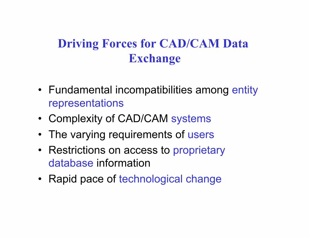
Driving Forces for CAD/CAM Data Exchange
• Fundamental incompatibilities among entity representations
• Complexity of CAD/CAM systems • The varying requirements of users • Restrictions on access to proprietary
database information • Rapid pace of technological change
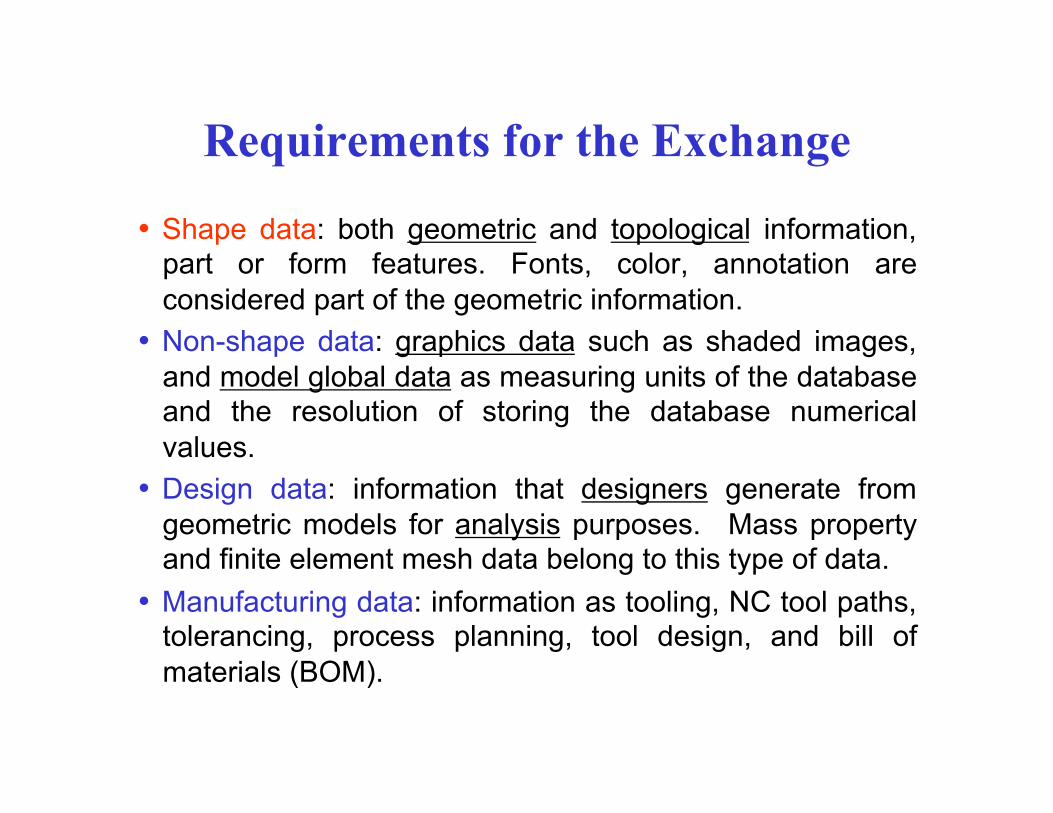
Requirements for the Exchange
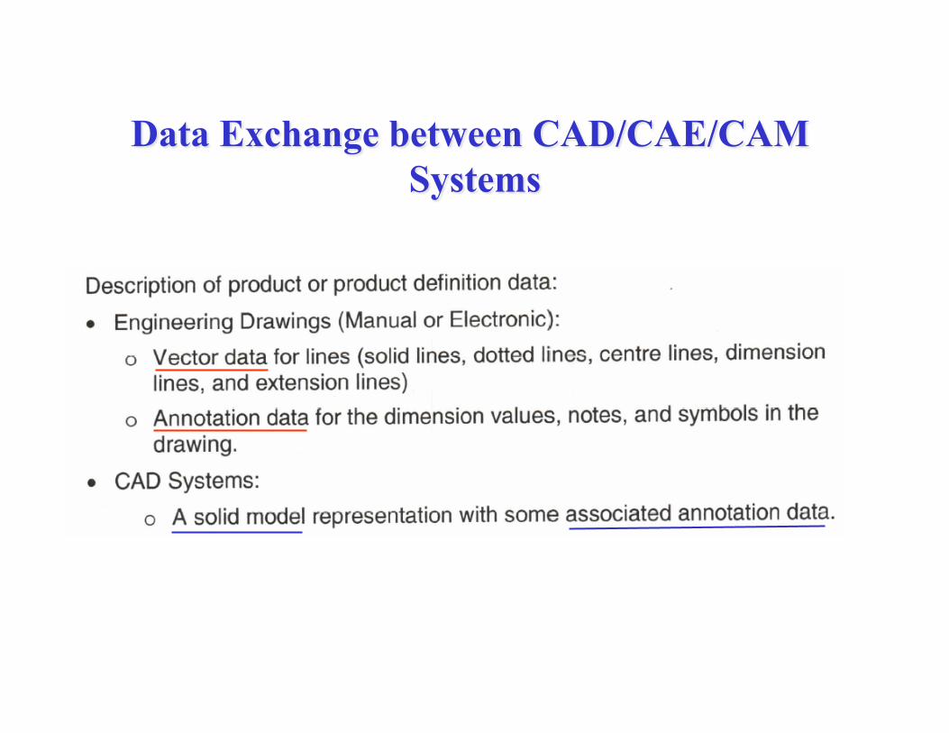
• Shape data: both geometric and topological information, part or form features. Fonts, color, annotation are considered part of the geometric information.
• Non-shape data: graphics data such as shaded images, and model global data as measuring units of the database and the resolution of storing the database numerical values.
• Design data: information that designers generate from geometric models for analysis purposes. Mass property and finite element mesh data belong to this type of data.
• Manufacturing data: information as tooling, NC tool paths, tolerancing, process planning, tool design, and bill of materials (BOM).
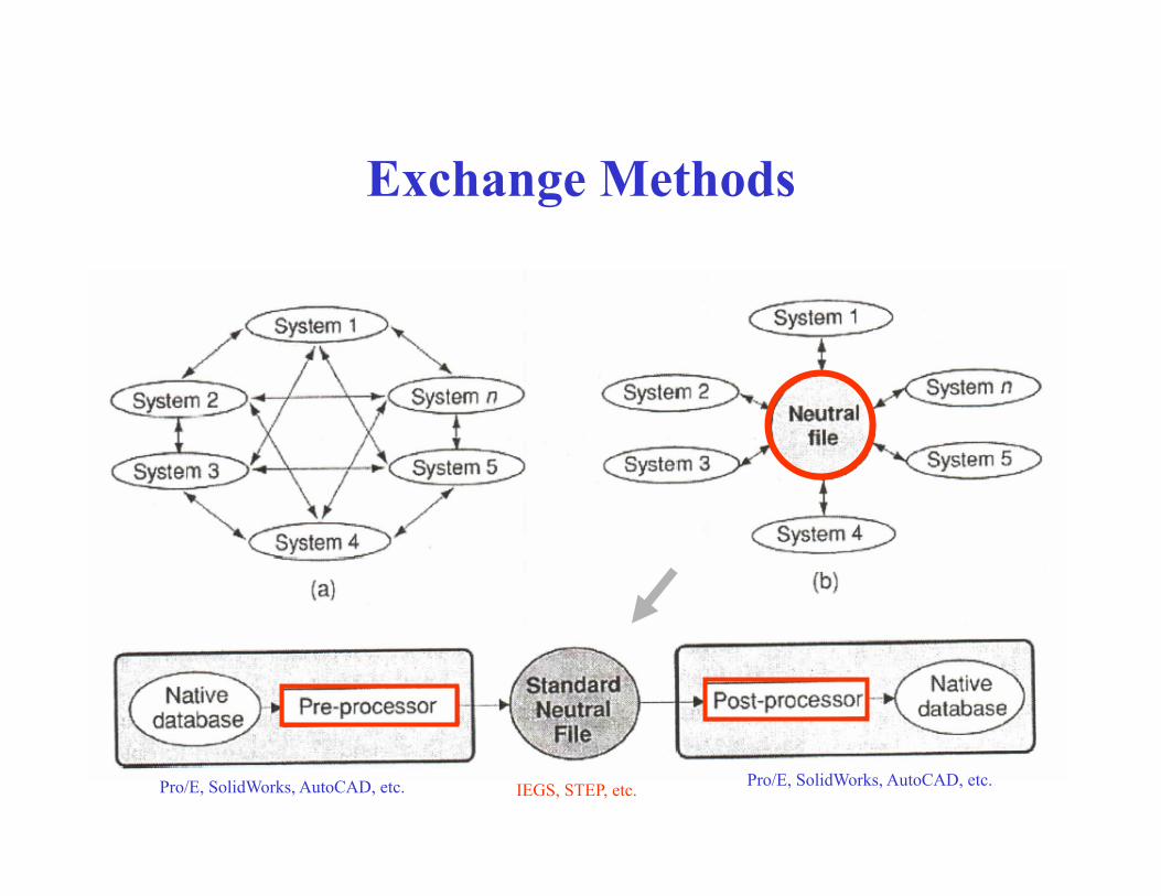
Exchange Methods
Pro/E, SolidWorks, AutoCAD, etc. Pro/E, SolidWorks, AutoCAD, etc. IEGS, STEP, etc.
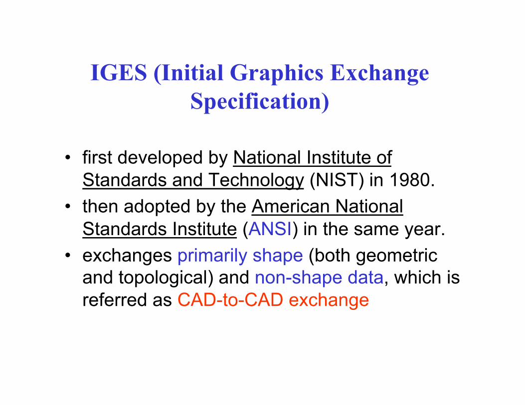
IGES (Initial Graphics Exchange Specification)
• first developed by National Institute of Standards and Technology (NIST) in 1980.
• then adopted by the American National Standards Institute (ANSI) in the same year.
• exchanges primarily shape (both geometric and topological) and non-shape data, which is referred as CAD-to-CAD exchange

IGES (Initial Graphics Exchange Specification)
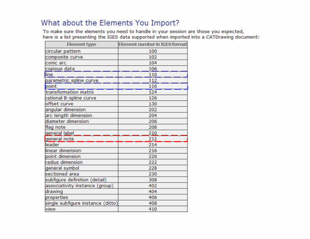
• codes a superset of common entities of all CAD/CAM systems to facilitate the translation between various systems
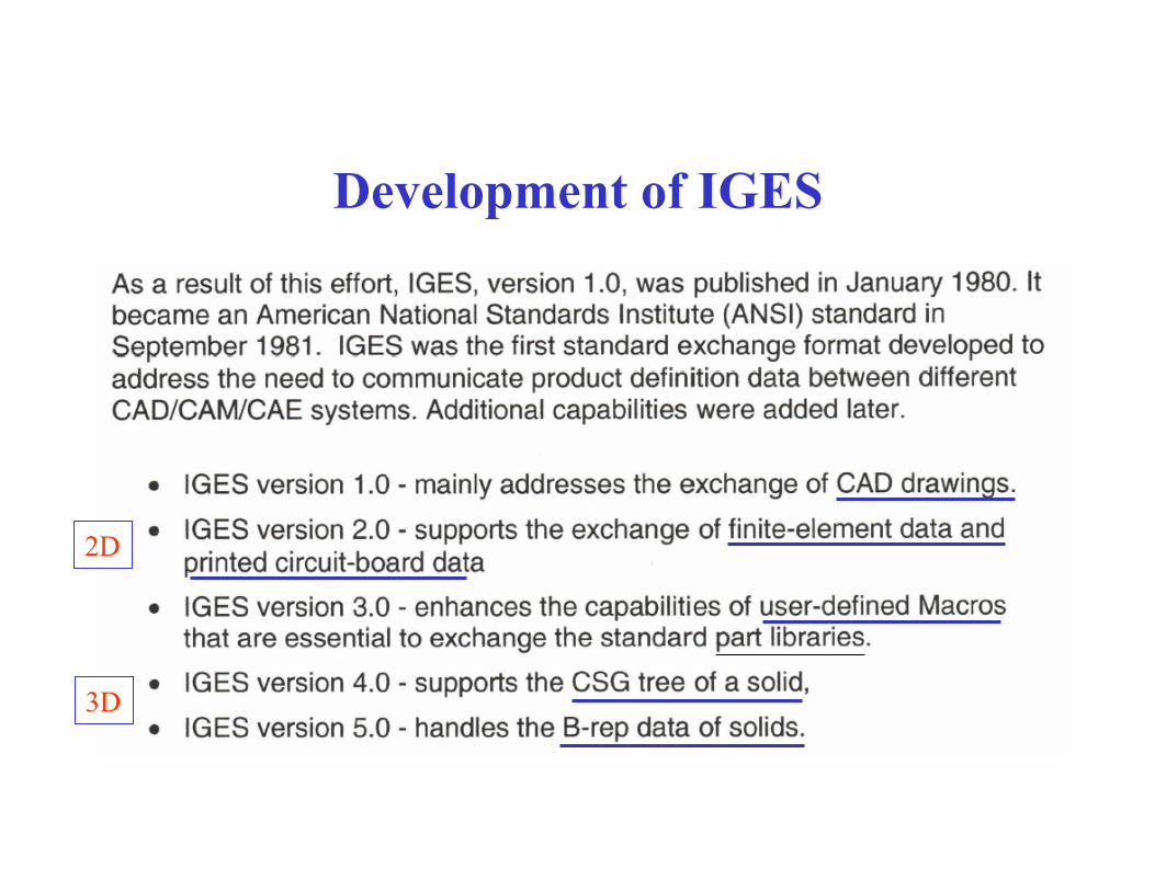
Development of IGES
2D
3D
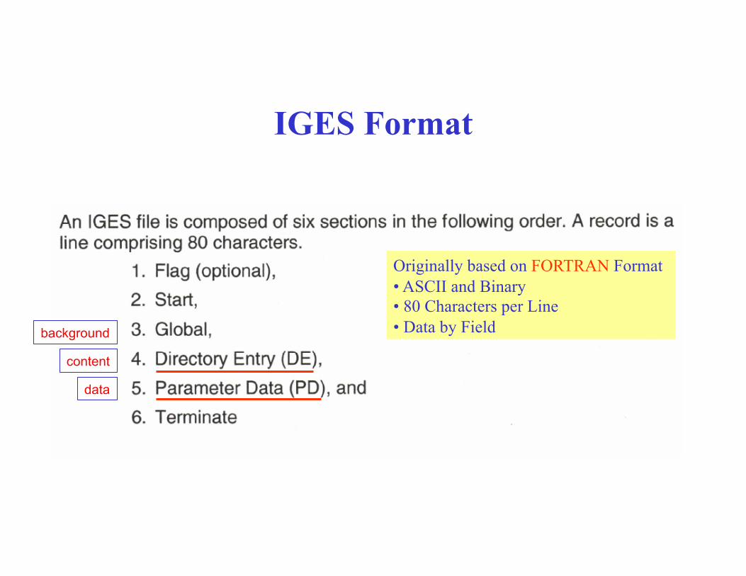
IGES Format
Originally based on FORTRAN Format • ASCII and Binary • 80 Characters per Line • Data by Field
data
background
content
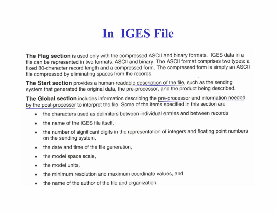
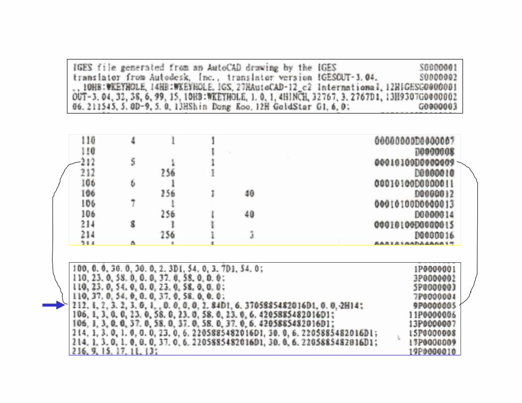
In IGES File

In IGES File
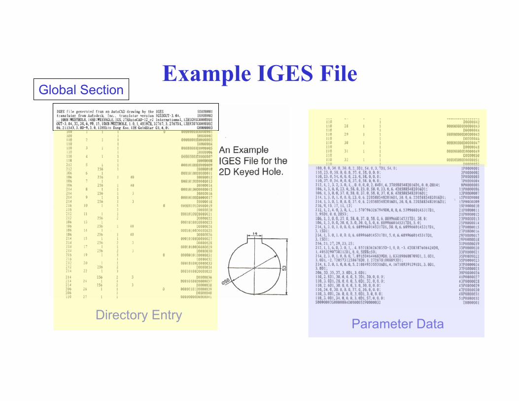
Example IGES File
Directory Entry Parameter Data
Global Section
data
background
content
PDES (Product Data Exchange Standard) (then Product Data Exchange Using STEP)
• to support any industrial application such as mechanical, electric, plant design, and architecture and engineering construction
• to include all four types of data which is relevant to the entire life-cycle of a product: design, analysis, manufacturing, quality assurance, testing, support, etc.
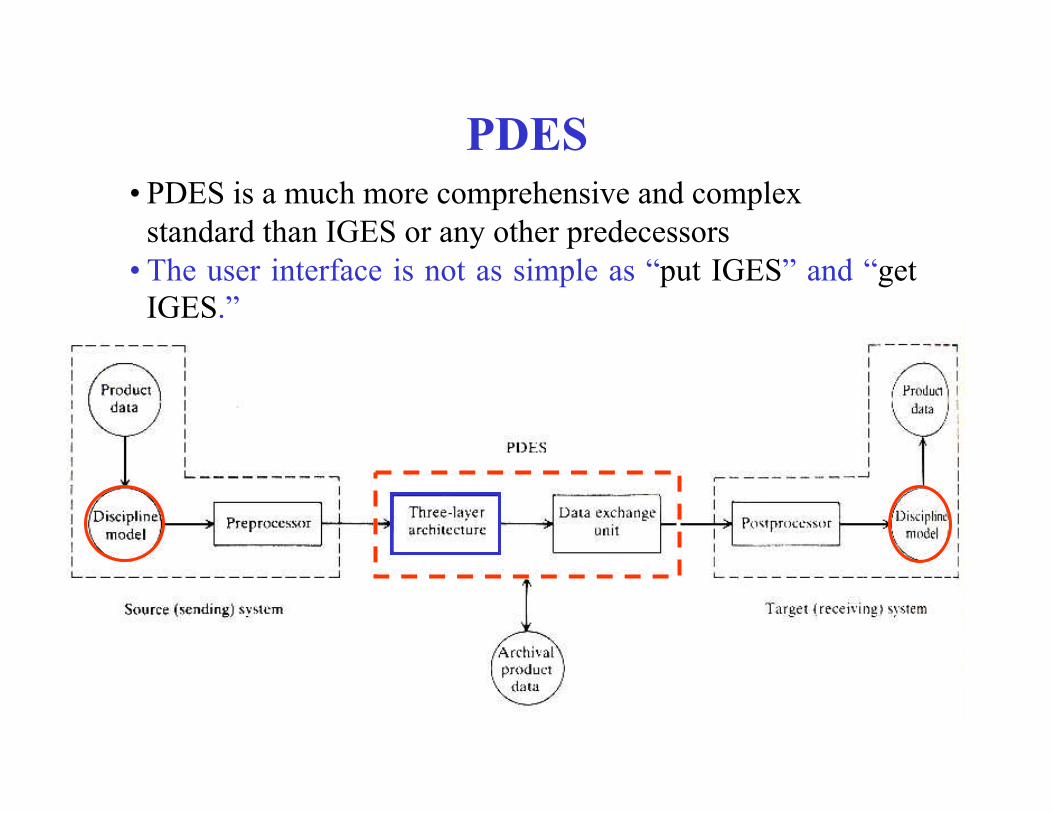
PDES • PDES is a much more comprehensive and complex
standard than IGES or any other predecessors • The user interface is not as simple as “put IGES” and “get
IGES.”
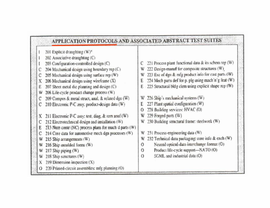
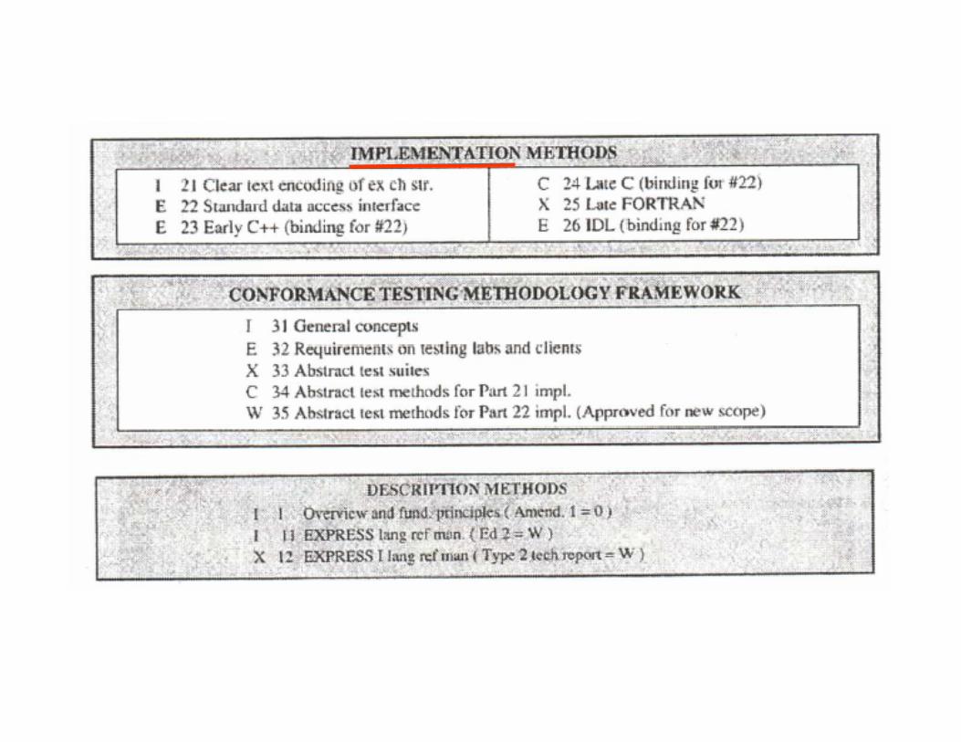
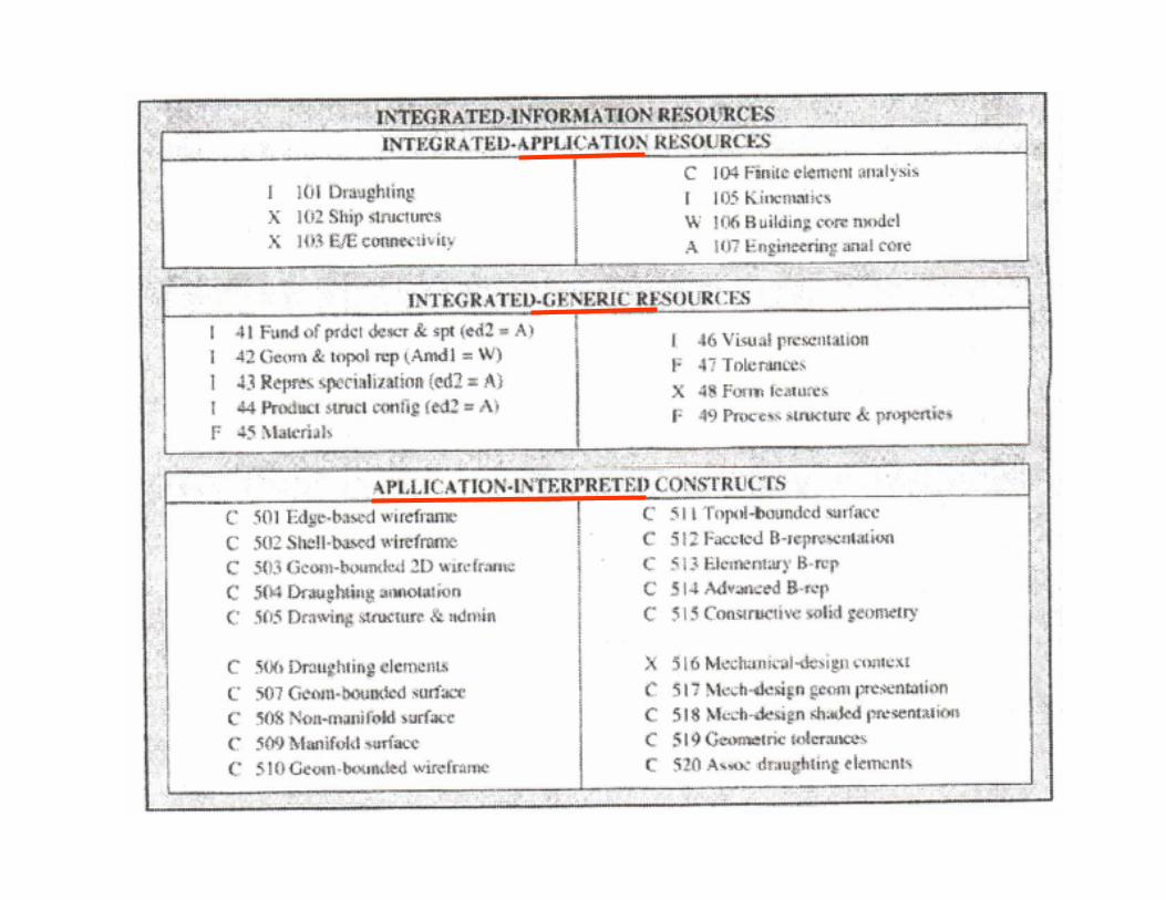
STEP (Standard for the Transfer and Exchange of Product Model Data)
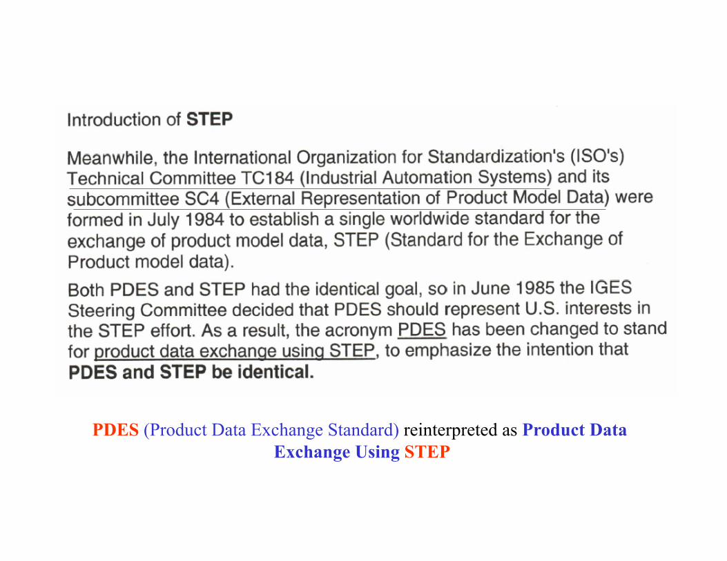
PDES (Product Data Exchange Standard) reinterpreted as Product Data Exchange Using STEP
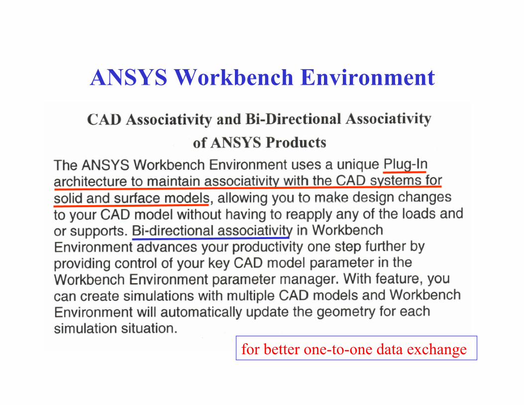
ANSYS Workbench Environment
for better one-to-one data exchange
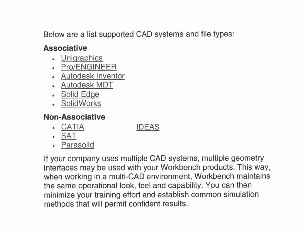
IDEAS
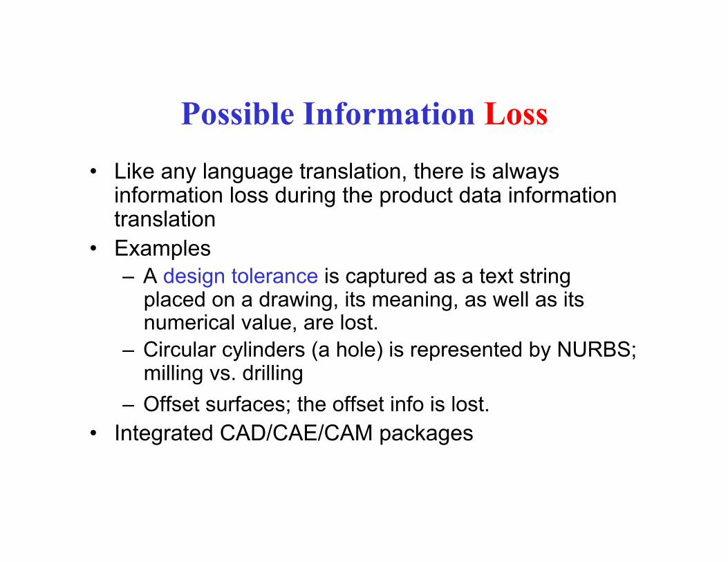
Possible Information Loss • Like any language translation, there is always
information loss during the product data information translation
• Examples – A design tolerance is captured as a text string
placed on a drawing, its meaning, as well as its numerical value, are lost.
– Circular cylinders (a hole) is represented by NURBS; milling vs. drilling
– Offset surfaces; the offset info is lost. • Integrated CAD/CAE/CAM packages
Quick Questions
• What is IGES, PDES, and STEP?
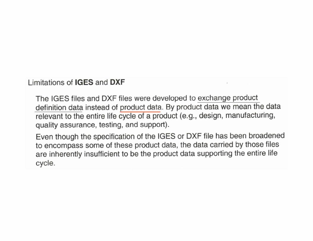
• What are the limitations of IGES?
• What need to be transferred?
• Why can’t the information be completed exchanged between CAD tools?