Embed Size (px)
Citation preview
F
ree
sca
le S
em
ico
nd
uc
tor,
I
Freescale Semiconductor, Inc.n
c..
.
MOTOROLA.COM/SEMICONDUCTORS
M68HC08Microcontrollers
DRM036/DRev. 0, 03/2003
Sine VoltagePowered 3-PhasePermanent MagnetSynchronous Motor with Hall Sensors
Designer ReferenceManual
For More Information On This Product,
Go to: www.freescale.com

F
ree
sca
le S
em
ico
nd
uc
tor,
I
Freescale Semiconductor, Inc.n
c..
.
For More Information On This Product,
Go to: www.freescale.com
F
ree
sca
le S
em
ico
nd
uc
tor,
IFreescale Semiconductor, Inc.
nc
...
Sine Voltage Powered 3-Phase Permanent Magnet Synchronous Motor with Hall SensorsDesigner Reference Manual — Rev 0
by: Jiri RybaMotorola Czech Systems LaboratoriesRoznov pod Radhostem, The Czech Republic
DRM036 — Rev 0 Designer Reference Manual
MOTOROLA 3 For More Information On This Product,
Go to: www.freescale.com
Revision history
F
ree
sca
le S
em
ico
nd
uc
tor,
I
Freescale Semiconductor, Inc.n
c..
.
To provide the most up-to-date information, the revision of our documents on the World Wide Web will be the most current. Your printed copy may be an earlier revision. To verify you have the latest information available, refer to:
http://www.motorola.com/semiconductors
The following revision history table summarizes changes contained in this document. For your convenience, the page number designators have been linked to the appropriate location.
Revision history
DateRevision
LevelDescription
PageNumber(s)
January,2003
1 Initial revision N/A
Designer Reference Manual DRM036 — Rev 0
4 MOTOROLA For More Information On This Product,
Go to: www.freescale.com
F
ree
sca
le S
em
ico
nd
uc
tor,
IFreescale Semiconductor, Inc.
nc
...
Designer Reference Manual — Sine Voltage Powered 3-ph PMS Motor
List of Sections
Section 1. Introduction . . . . . . . . . . . . . . . . . . . . . . . . . . . 13
Section 2. System Description. . . . . . . . . . . . . . . . . . . . . 17
Section 3. Hardware Design. . . . . . . . . . . . . . . . . . . . . . . 25
Section 4. Software Design . . . . . . . . . . . . . . . . . . . . . . . 35
Section 5. Application Setup . . . . . . . . . . . . . . . . . . . . . . 47
Appendix A. References. . . . . . . . . . . . . . . . . . . . . . . . . . 57
Appendix B. Glossary. . . . . . . . . . . . . . . . . . . . . . . . . . . . 59
DRM036 — Rev 0 Designer Reference Manual
MOTOROLA 5 For More Information On This Product,
Go to: www.freescale.com

List of Sections
F
ree
sca
le S
em
ico
nd
uc
tor,
I
Freescale Semiconductor, Inc.n
c..
.
Designer Reference Manual DRM036 — Rev 0
6 MOTOROLA For More Information On This Product,
Go to: www.freescale.com
F
ree
sca
le S
em
ico
nd
uc
tor,
IFreescale Semiconductor, Inc.
nc
...
Designer Reference Manual — Sine Voltage Powered 3-ph PMS Motor
Table of Contents
Section 1. Introduction
1.1 Contents . . . . . . . . . . . . . . . . . . . . . . . . . . . . . . . . . . . . . . . . . .13
1.2 Overview. . . . . . . . . . . . . . . . . . . . . . . . . . . . . . . . . . . . . . . . . .13
1.3 Brief Description . . . . . . . . . . . . . . . . . . . . . . . . . . . . . . . . . . . .13
1.4 68HC908MR32 Features . . . . . . . . . . . . . . . . . . . . . . . . . . . . .14
Section 2. System Description
2.1 Contents . . . . . . . . . . . . . . . . . . . . . . . . . . . . . . . . . . . . . . . . . .17
2.2 Application Features . . . . . . . . . . . . . . . . . . . . . . . . . . . . . . . . .17
2.3 Target Motor Theory . . . . . . . . . . . . . . . . . . . . . . . . . . . . . . . . .20
Section 3. Hardware Design
3.1 Contents . . . . . . . . . . . . . . . . . . . . . . . . . . . . . . . . . . . . . . . . . .25
3.2 Hardware Configuration . . . . . . . . . . . . . . . . . . . . . . . . . . . . . .25
3.3 MC68HC908MR32 Control Board . . . . . . . . . . . . . . . . . . . . . .26
3.4 3-Phase BLDC Low Voltage Power Stage . . . . . . . . . . . . . . . .28
3.5 EVM Motor Board . . . . . . . . . . . . . . . . . . . . . . . . . . . . . . . . . . .30
3.6 Hardware Documentation . . . . . . . . . . . . . . . . . . . . . . . . . . . . .32
Section 4. Software Design
4.1 Contents . . . . . . . . . . . . . . . . . . . . . . . . . . . . . . . . . . . . . . . . . .35
4.2 Software Design . . . . . . . . . . . . . . . . . . . . . . . . . . . . . . . . . . . .35
4.3 Software Data Flow . . . . . . . . . . . . . . . . . . . . . . . . . . . . . . . . .35
DRM036 — Rev 0 Designer Reference Manual
MOTOROLA 7 For More Information On This Product,
Go to: www.freescale.com
Table of Contents
F
ree
sca
le S
em
ico
nd
uc
tor,
I
Freescale Semiconductor, Inc.n
c..
.
4.4 Software Processes . . . . . . . . . . . . . . . . . . . . . . . . . . . . . . . . .37
4.5 PC Master Software (Remote) Operating Mode. . . . . . . . . . . .45
Section 5. Application Setup
5.1 Contents . . . . . . . . . . . . . . . . . . . . . . . . . . . . . . . . . . . . . . . . . .47
5.2 Warning . . . . . . . . . . . . . . . . . . . . . . . . . . . . . . . . . . . . . . . . . .47
5.3 Hardware Setup . . . . . . . . . . . . . . . . . . . . . . . . . . . . . . . . . . . .47
5.4 Software Setup . . . . . . . . . . . . . . . . . . . . . . . . . . . . . . . . . . . . .50
5.5 Executing the Application . . . . . . . . . . . . . . . . . . . . . . . . . . . . .51
Appendix A. References
Appendix B. Glossary
Designer Reference Manual DRM036 — Rev 0
8 MOTOROLA For More Information On This Product,
Go to: www.freescale.com
F
ree
sca
le S
em
ico
nd
uc
tor,
IFreescale Semiconductor, Inc.
nc
...
Designer Reference Manual — Sine Voltage Powered 3-ph PMS Motor
List of Tables
Table Title Page
3-1 Electrical Characteristics of Control Board . . . . . . . . . . . . . . . .283-2 Electrical Characteristics of the 3-Ph BLDC
Low Voltage Power Stage . . . . . . . . . . . . . . . . . . . . . . . . . . . .303-3 Electrical Characteristics of the EVM Motor Board. . . . . . . . . .313-4 Characteristics of the BLDC motor . . . . . . . . . . . . . . . . . . . . . .325-1 MCHC908MR32 Board Jumper Settings . . . . . . . . . . . . . . . . .495-2 Motor Application States. . . . . . . . . . . . . . . . . . . . . . . . . . . . . .52
DRM036 — Rev 0 Designer Reference Manual
MOTOROLA 9 For More Information On This Product,
Go to: www.freescale.com

List of Tables
F
ree
sca
le S
em
ico
nd
uc
tor,
I
Freescale Semiconductor, Inc.n
c..
.
Designer Reference Manual DRM036 — Rev 0
10 MOTOROLA For More Information On This Product,
Go to: www.freescale.com
F
ree
sca
le S
em
ico
nd
uc
tor,
IFreescale Semiconductor, Inc.
nc
...
Designer Reference Manual — Sine Voltage Powered 3-ph PMS Motor
List of Figures
Figure Title Page
2-1 System Concept . . . . . . . . . . . . . . . . . . . . . . . . . . . . . . . . . . . .192-2 Three Phase Permanent Magnet Motor - Cross Section . . . . .202-3 Voltage is 90° Relative to Rotor Flux . . . . . . . . . . . . . . . . . . . .222-4 Stator Current is 90° Relative to Rotor Flux . . . . . . . . . . . . . . .232-5 Voltage Vector in the Direction of the Current Vector. . . . . . . .233-1 H/W System Configuration . . . . . . . . . . . . . . . . . . . . . . . . . . . .263-2 MC68HC908MR32 Control Board . . . . . . . . . . . . . . . . . . . . . .273-3 Block Diagram . . . . . . . . . . . . . . . . . . . . . . . . . . . . . . . . . . . . .294-1 Main Data Flow. . . . . . . . . . . . . . . . . . . . . . . . . . . . . . . . . . . . .364-2 Calculation of Hall Sensor Period . . . . . . . . . . . . . . . . . . . . . . .384-3 Difference between Motor Position
and Generated Sine Wave . . . . . . . . . . . . . . . . . . . . . . . . . . . .394-4 Control with Minimal Reactive Power . . . . . . . . . . . . . . . . . . . .424-5 Measured Reactive Power for Different Torque and Speed. . .435-1 H/W System Configuration . . . . . . . . . . . . . . . . . . . . . . . . . . . .485-2 MC68HC908MR32 Jumper Reference. . . . . . . . . . . . . . . . . . .495-3 Target Build Selection. . . . . . . . . . . . . . . . . . . . . . . . . . . . . . . .515-4 MC68HC908MR32 Board - Control Elements . . . . . . . . . . . . .535-5 USER LEDs, PWM LEDs, and RESET . . . . . . . . . . . . . . . . . .535-6 PC master software control window . . . . . . . . . . . . . . . . . . . . .55
DRM036 — Rev 0 Designer Reference Manual
MOTOROLA 11 For More Information On This Product,
Go to: www.freescale.com

List of Figures
F
ree
sca
le S
em
ico
nd
uc
tor,
I
Freescale Semiconductor, Inc.n
c..
.
Designer Reference Manual DRM036 — Rev 0
12 MOTOROLA For More Information On This Product,
Go to: www.freescale.com
F
ree
sca
le S
em
ico
nd
uc
tor,
IFreescale Semiconductor, Inc.
nc
...
Designer Reference Manual — Sine Voltage Powered 3-ph PMS Motor
Section 1. Introduction
1.1 Contents
1.2 Overview. . . . . . . . . . . . . . . . . . . . . . . . . . . . . . . . . . . . . . . . . .13
1.3 Brief Description . . . . . . . . . . . . . . . . . . . . . . . . . . . . . . . . . . . .13
1.4 68HC908MR32 Features . . . . . . . . . . . . . . . . . . . . . . . . . . . . .14
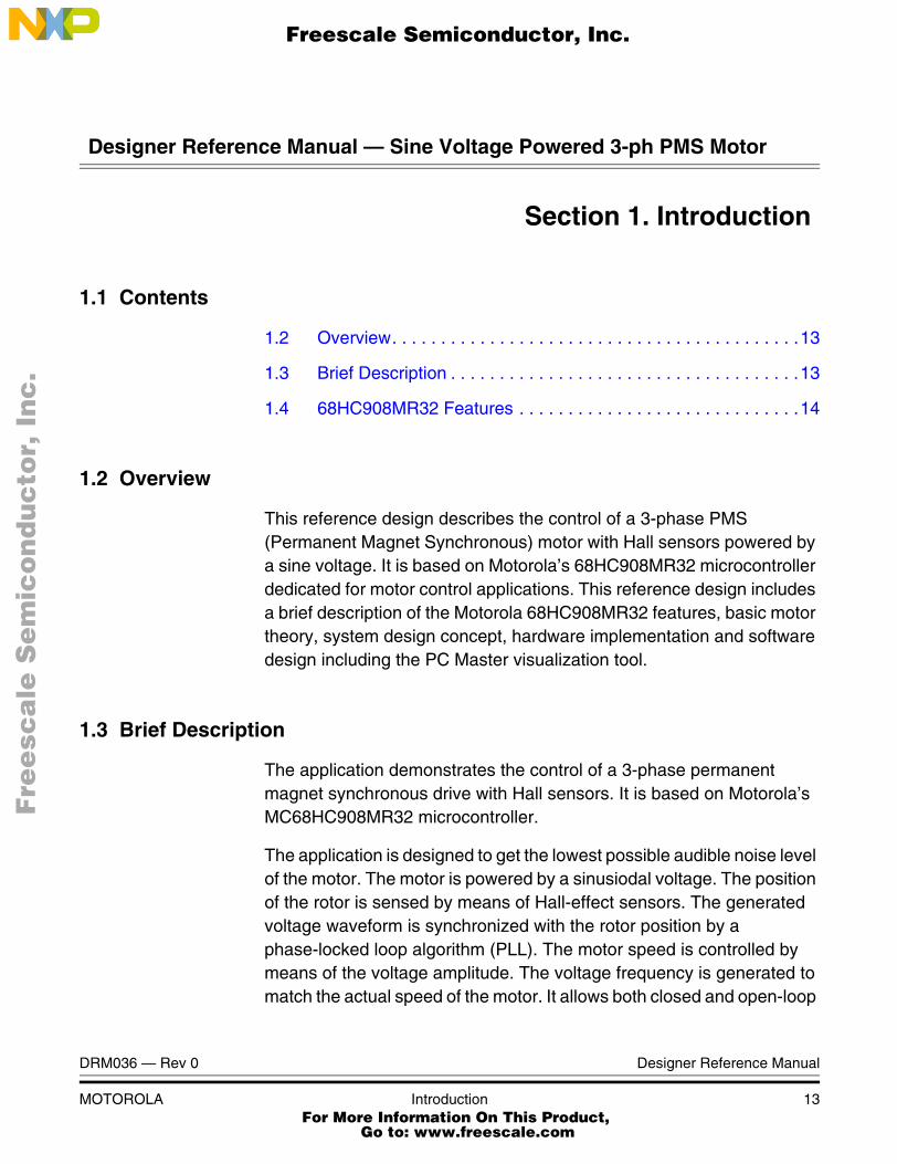
1.2 Overview
This reference design describes the control of a 3-phase PMS (Permanent Magnet Synchronous) motor with Hall sensors powered by a sine voltage. It is based on Motorola’s 68HC908MR32 microcontroller dedicated for motor control applications. This reference design includes a brief description of the Motorola 68HC908MR32 features, basic motor theory, system design concept, hardware implementation and software design including the PC Master visualization tool.
1.3 Brief Description
The application demonstrates the control of a 3-phase permanent magnet synchronous drive with Hall sensors. It is based on Motorola’s MC68HC908MR32 microcontroller.
The application is designed to get the lowest possible audible noise level of the motor. The motor is powered by a sinusiodal voltage. The position of the rotor is sensed by means of Hall-effect sensors. The generated voltage waveform is synchronized with the rotor position by a phase-locked loop algorithm (PLL). The motor speed is controlled by means of the voltage amplitude. The voltage frequency is generated to match the actual speed of the motor. It allows both closed and open-loop
DRM036 — Rev 0 Designer Reference Manual
MOTOROLA Introduction 13 For More Information On This Product,
Go to: www.freescale.com
Introduction
F
ree
sca
le S
em
ico
nd
uc
tor,
I
Freescale Semiconductor, Inc.n
c..
.
speed control. This PMS motor control application with Hall sensors operates in two modes:
1. Manual operating mode
2. PC master software (remote) operating mode
1.4 68HC908MR32 Features
The MC68HC908MR32 is a member of the low-cost, high-performance M68HC08 Family of 8-bit microcontroller units (MCUs). The M68HC08 Family is based on the customer-specified integrated circuit (CISC) design strategy. All MCUs in the family use the enhanced M68HC08 central processor unit (CPU08) and are available with a variety of modules, memory sizes and types, and package types:
Features of the MC68HC908MR32 include:
• High-performance M68HC08 architecture
• Fully upward-compatible object code with M6805, M146805, and M68HC05 Families
• 8-MHz internal bus frequency
• 32Kbytes of on-chip electrically erasable in-circuit programmable Read Only Memory (FLASH)
• On-chip programming firmware for use with host personal computer
• Flash data security
• 768 bytes of on-chip Random Access Memory (RAM)
• 12-bit, 6-channel center-aligned or edge-aligned pulse width modulator with optional independent and complementary mode
• Serial peripheral interface module (SPI)
• Serial communications interface module (SCI)
• 16-bit, 4-channel timer interface module (TIMA)
• 16-bit, 2-channel timer interface module (TIMB)
• Clock generator module (CGM)
Designer Reference Manual DRM036 — Rev 0
14 Introduction MOTOROLA For More Information On This Product,
Go to: www.freescale.com
Introduction68HC908MR32 Features
F
ree
sca
le S
em
ico
nd
uc
tor,
I
Freescale Semiconductor, Inc.n
c..
.
• Low-voltage inhibit (LVi) module with software selectable trip points
• 10-bit, 10-channel analog-to-digital converter (ADC) with multiplexed inputs
• Computer operating properly (COP) watchdog timer
DRM036 — Rev 0 Designer Reference Manual
MOTOROLA Introduction 15 For More Information On This Product,
Go to: www.freescale.com

Introduction
F
ree
sca
le S
em
ico
nd
uc
tor,
I
Freescale Semiconductor, Inc.n
c..
.
Designer Reference Manual DRM036 — Rev 0
16 Introduction MOTOROLA For More Information On This Product,
Go to: www.freescale.com
F
ree
sca
le S
em
ico
nd
uc
tor,
IFreescale Semiconductor, Inc.
nc
...
Designer Reference Manual — Sine Voltage Powered 3-ph PMS Motor
Section 2. System Description
2.1 Contents
2.2 Application Features . . . . . . . . . . . . . . . . . . . . . . . . . . . . . . . . .17
2.3 Target Motor Theory . . . . . . . . . . . . . . . . . . . . . . . . . . . . . . . . .20
2.2 Application Features
The control strategy is designed to optimally utilize features of controller 68HC908MR32. The application provides following features:
• sine voltage powered 3-phase PM synchronous motor
• position sensing using three Hall sensors
• low audible noise of motor
• closed or open speed loop operation
• high motor efficiency
• motor deceleration (energy is returned to the dc-bus)
• DC-Bus voltage ripple cancellation
• manual (speed pot, start-stop switch) / PC master control (RS 232)
• recognition of the spinning motor after CPU reset
• limitation of dc-bus over-voltage during deceleration
• over voltage protection
• over current protection
• dc-bus voltage sensing
• PC master software
DRM036/D — Rev 0 Designer Reference Manual
MOTOROLA System Description 17 For More Information On This Product,
Go to: www.freescale.com
System Description
F
ree
sca
le S
em
ico
nd
uc
tor,
I
Freescale Semiconductor, Inc.n
c..
.
• memory requirements
– RAM 135 Bytes
– Flash 3485 Bytes
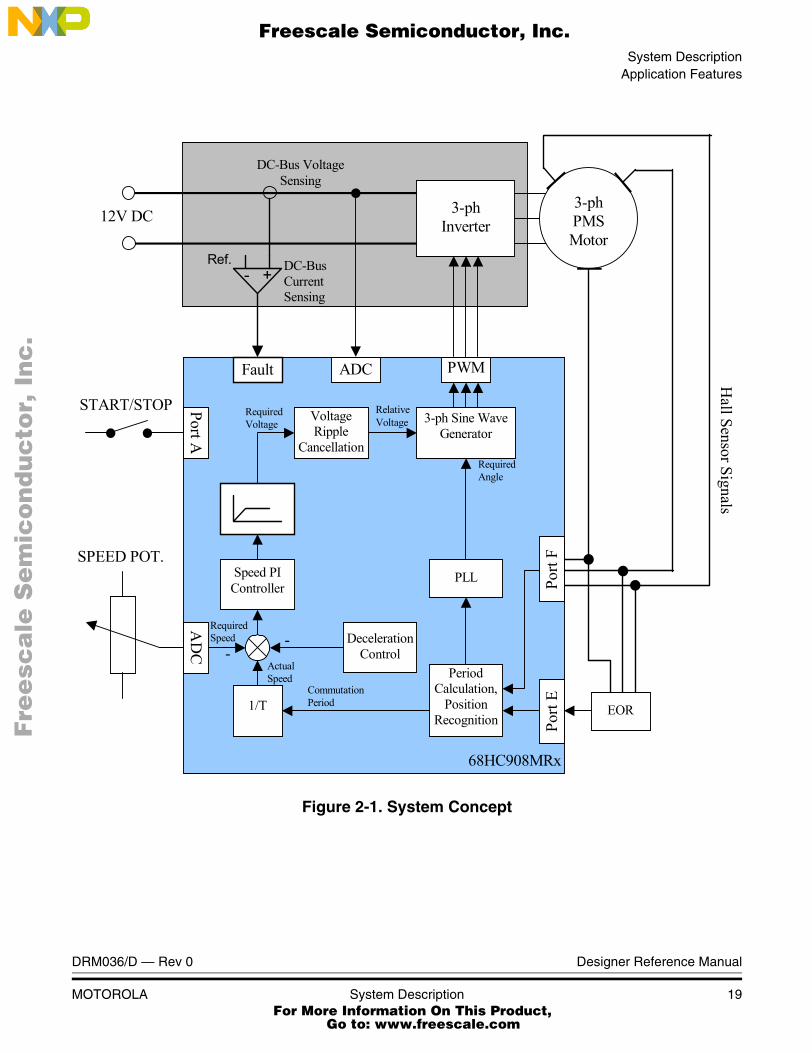
The Figure 2-1 shows the system concept of the designed application. The application was designed to control a PMS motor driving a ventilator. Speed of the motor is controlled by the amplitude of the voltage vector. The direction of the voltage vector depends on the rotor position. The PLL is used to synchronize the calculated vector position with the actual one. The calculated position is updated in PWM reload at 16kHz. The position resolution is 216 points per period.
This application uses the Hall sensors to obtain the rotor position. The Hall sensor consists of three sensors (Sensor A, Sensor B, Sensor C). The HC908MR32 control board contains EOR logic, which reflect change of any sensor to the one output. This output is connected to the Timer A channel 2. The example application, which is a subject of this design uses three hall sensors, however, the control algorithm can be used to control a motor having only one Hall senor. In this case the merits of this design are much more obvious.
The PI controller is used to control the speed of motor. The output of the controller sets the desired value of the phase voltage amplitude. The voltage ripple cancellation block recalculates the absolute voltage value to the value, which is relative to the actual dc-bus voltage level. This minimizes the influence of the dc-bus voltage changes (ripples) to the generated phase voltage.
The deceleration control algorithm controls the deceleration of the motor to avoid dc-bus over-voltage. In this application the maximum voltage is kept at 16V.
The application also contains PC master software, which supports communication between the target microcontroller and PC via an RS232 serial interface. This tool allows a real- time access to any memory location of the target processor. The user can debug or remotely control the application, using a user-friendly graphical interface.
Designer Reference Manual DRM036/D — Rev 0
18 System Description MOTOROLA For More Information On This Product,
Go to: www.freescale.com
System DescriptionApplication Features
F
ree
sca
le S
em
ico
nd
uc
tor,
I
Freescale Semiconductor, Inc.n
c..
.
Figure 2-1. System Concept
SPEED POT.
Period Calculation,
Position Recognition
1/T
Speed PI Controller
PLL
3-ph Sine WaveGenerator
AD
C
Port
E
68HC908MRx
Port A
3-ph PMS Motor
DC-Bus Voltage Sensing
3-ph Inverter
START/STOP
PWM
Required Speed
Actual Speed
Commutation Period
Required Voltage
Required Angle
Hall Sensor Signals
12V DC
Fault
DC-Bus Current Sensing
- + Ref.
ADC
Deceleration Control
- -
Voltage Ripple
Cancellation
Relative Voltage
EOR
Port
F
DRM036/D — Rev 0 Designer Reference Manual
MOTOROLA System Description 19 For More Information On This Product,
Go to: www.freescale.com
System Description
F
ree
sca
le S
em
ico
nd
uc
tor,
I
Freescale Semiconductor, Inc.n
c..
.
2.3 Target Motor Theory
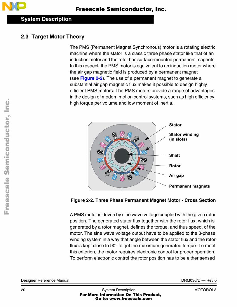
The PMS (Permanent Magnet Synchronous) motor is a rotating electric machine where the stator is a classic three phase stator like that of an induction motor and the rotor has surface-mounted permanent magnets. In this respect, the PMS motor is equivalent to an induction motor where the air gap magnetic field is produced by a permanent magnet (see Figure 2-2). The use of a permanent magnet to generate a substantial air gap magnetic flux makes it possible to design highly efficient PMS motors. The PMS motors provide a range of advantages in the design of modern motion control systems, such as high efficiency, high torque per volume and low moment of inertia.
Figure 2-2. Three Phase Permanent Magnet Motor - Cross Section
A PMS motor is driven by sine wave voltage coupled with the given rotor position. The generated stator flux together with the rotor flux, which is generated by a rotor magnet, defines the torque, and thus speed, of the motor. The sine wave voltage output have to be applied to the 3-phase winding system in a way that angle between the stator flux and the rotor flux is kept close to 90° to get the maximum generated torque. To meet this criterion, the motor requires electronic control for proper operation. To perform electronic control the rotor position has to be either sensed
Stator
Stator winding(in slots)
Shaft
Rotor
Air gap
Permanent magnets
Designer Reference Manual DRM036/D — Rev 0
20 System Description MOTOROLA For More Information On This Product,
Go to: www.freescale.com
System DescriptionTarget Motor Theory
F
ree
sca
le S
em
ico
nd
uc
tor,
I
Freescale Semiconductor, Inc.n
c..
.
by position sensors or calculated by means of sensorless control algorithm.
The presented application uses the Hall sensors to sense actual position of the rotor. The sensor output is read by the MCU, and used for synchronizing the generated sine wave.
The PMS motor model is defined by the following equations:
(EQ 2-1.)
(EQ 2-2.)
(EQ 2-3.)
where:
• - Space vector of stator voltage
• - Space vector of stator current
• rs- Stator resistance
• - Space vector of magnetic flux
• - Space vector of rotor magnetic flux evoked by the permanent magnet
• Te- Electrical torque
• is angle between vectors of stator current and rotor magnetic flux
The speed of the motor can be controlled by an amplitude of the voltage vector, while the direction of the voltage vector depends on the rotor position. Several methods can be used to control the voltage vector direction.
The three basic method are:
1. vector of stator voltage is placed 90° relative to the vector of rotor magnetic flux
Us rs Is⋅dψsdt---------+=
ψs Ls Is ψr+⋅=
Te Is ψ Is∠ ψ,( )sin⋅ ⋅ Is ψr Is∠ ψr,( )sin⋅ ⋅= =
Us
Is
Ψ
Ψr
is∠ ψ, r
DRM036/D — Rev 0 Designer Reference Manual
MOTOROLA System Description 21 For More Information On This Product,
Go to: www.freescale.com
System Description
F
ree
sca
le S
em
ico
nd
uc
tor,
I
Freescale Semiconductor, Inc.n
c..
.
2. vector of stator current is kept 90° relative to the vector of rotor magnetic flux
3. voltage vector is kept in the direction of the current vector.
It is desired to run the motor with maximum efficiency. In this case, the angle of current is higher than 90° relative to the rotor magnetic flux, but lower than in method 3, where the current has the same direction as the voltage. The motor parameters have to be known, or some experimental control strategy has to be used to achieve this criterion.
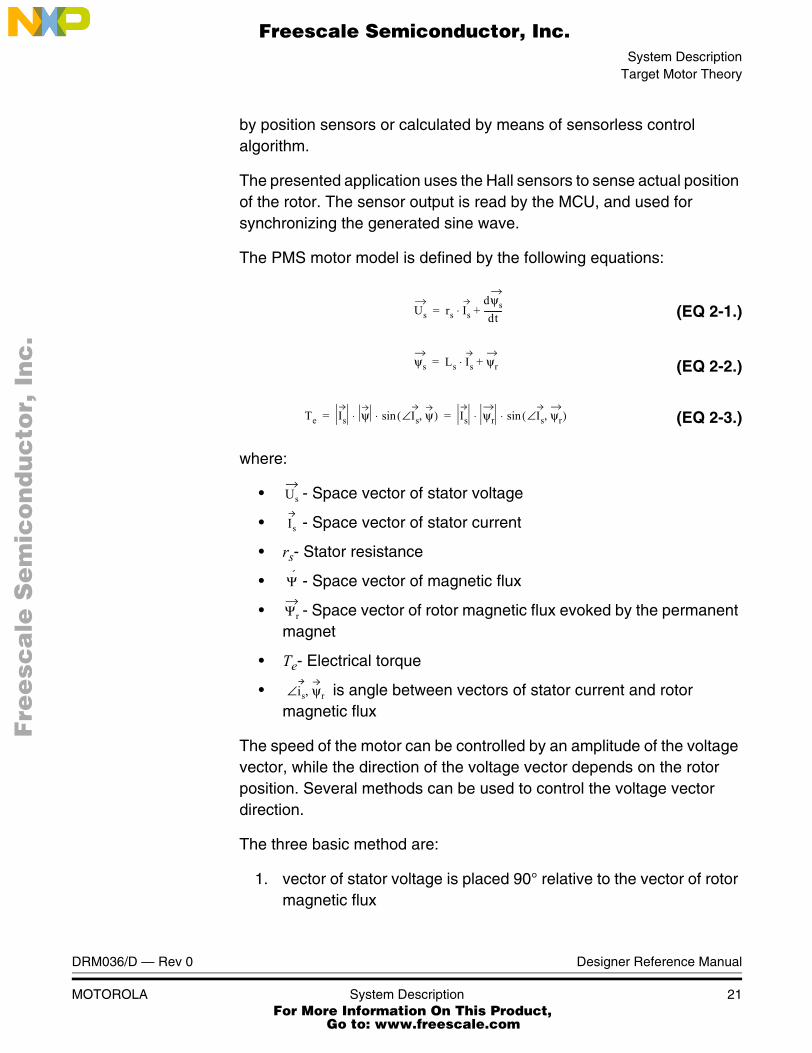
2.3.1 Vector of Stator Voltage Is Placed 90° Relative to the Vector of Rotor Magnetic Flux
The control strategy keeps the vector of stator voltage at 90° relative to the vector of rotor magnetic flux. This control strategy is shown in Figure 2-3. The advantage of this strategy is a simplicity. The only feedback signal needed for driving the motor is the rotor position. The presented application is based on this control strategy with some enhancements to achieve the best efficiency of the motor.
Figure 2-3. Voltage is 90° Relative to Rotor Flux
2.3.2 Vector of Stator Current Is Kept 90° Relative to the Vector of Rotor Magnetic Flux
This situation is shown in Figure 2-4. As can be seen from equation (EQ 2-3.) the optimal torque is generated when the vector of the stator
Ψ
Ψr
Ψs
jω.Ls.Is
Us
RsIs
E
Is
90°
Designer Reference Manual DRM036/D — Rev 0
22 System Description MOTOROLA For More Information On This Product,
Go to: www.freescale.com
System DescriptionTarget Motor Theory
F
ree
sca
le S
em
ico
nd
uc
tor,
I
Freescale Semiconductor, Inc.n
c..
.
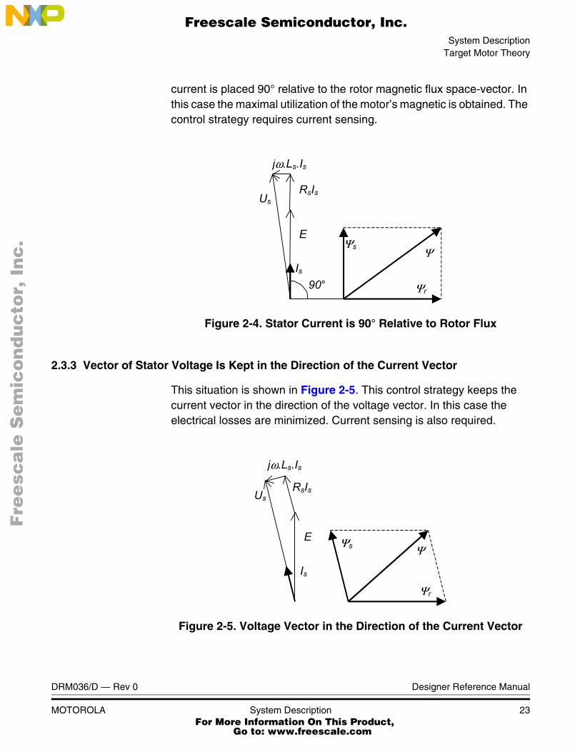
current is placed 90° relative to the rotor magnetic flux space-vector. In this case the maximal utilization of the motor’s magnetic is obtained. The control strategy requires current sensing.
Figure 2-4. Stator Current is 90° Relative to Rotor Flux
2.3.3 Vector of Stator Voltage Is Kept in the Direction of the Current Vector
This situation is shown in Figure 2-5. This control strategy keeps the current vector in the direction of the voltage vector. In this case the electrical losses are minimized. Current sensing is also required.
Figure 2-5. Voltage Vector in the Direction of the Current Vector
jω.Ls.Is
Ψr
Ψs Ψ
Us RsIs
E
Is 90°
Us
jω.Ls.Is
Ψr
Ψs Ψ
RsIs
E
Is
DRM036/D — Rev 0 Designer Reference Manual
MOTOROLA System Description 23 For More Information On This Product,
Go to: www.freescale.com

System Description
F
ree
sca
le S
em
ico
nd
uc
tor,
I
Freescale Semiconductor, Inc.n
c..
.
Designer Reference Manual DRM036/D — Rev 0
24 System Description MOTOROLA For More Information On This Product,
Go to: www.freescale.com

F
ree
sca
le S
em
ico
nd
uc
tor,
IFreescale Semiconductor, Inc.
nc
...
Designer Reference Manual — Sine Voltage Powered 3-ph PMS Motor
Section 3. Hardware Design
3.1 Contents
3.2 Hardware Configuration . . . . . . . . . . . . . . . . . . . . . . . . . . . . . .25
3.3 MC68HC908MR32 Control Board . . . . . . . . . . . . . . . . . . . . . .26
3.4 3-Phase BLDC Low Voltage Power Stage . . . . . . . . . . . . . . . .28
3.5 EVM Motor Board . . . . . . . . . . . . . . . . . . . . . . . . . . . . . . . . . . .30
3.6 Hardware Documentation . . . . . . . . . . . . . . . . . . . . . . . . . . . . .32
3.2 Hardware Configuration
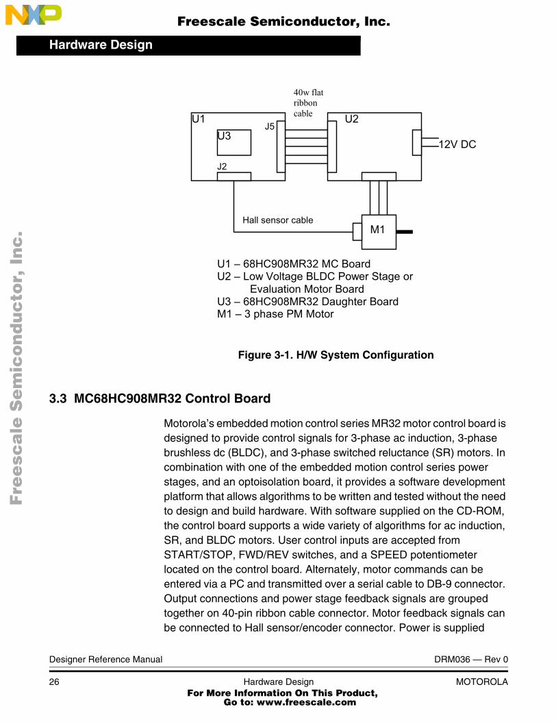
The system configuration is shown in Figure 3-1 It consists of:
• 68HC908MR32 controller board
• Power Stage (3-phase BLDC Low Voltage Power Stage or EVM Motor Board)
• 3ph PM synchronous motor with three Hall sensors
DRM036 — Rev 0 Designer Reference Manual
MOTOROLA Hardware Design 25 For More Information On This Product,
Go to: www.freescale.com
Hardware Design
F
ree
sca
le S
em
ico
nd
uc
tor,
I
Freescale Semiconductor, Inc.n
c..
.
Figure 3-1. H/W System Configuration
3.3 MC68HC908MR32 Control Board
Motorola’s embedded motion control series MR32 motor control board is designed to provide control signals for 3-phase ac induction, 3-phase brushless dc (BLDC), and 3-phase switched reluctance (SR) motors. In combination with one of the embedded motion control series power stages, and an optoisolation board, it provides a software development platform that allows algorithms to be written and tested without the need to design and build hardware. With software supplied on the CD-ROM, the control board supports a wide variety of algorithms for ac induction, SR, and BLDC motors. User control inputs are accepted from START/STOP, FWD/REV switches, and a SPEED potentiometer located on the control board. Alternately, motor commands can be entered via a PC and transmitted over a serial cable to DB-9 connector. Output connections and power stage feedback signals are grouped together on 40-pin ribbon cable connector. Motor feedback signals can be connected to Hall sensor/encoder connector. Power is supplied
U1 68HC908MR32 MC Board U2 Low Voltage BLDC Power Stage or Evaluation Motor Board U3 68HC908MR32 Daughter Board M1 3 phase PM Motor
M1
U3 U2 U1
Hall sensor cable
J2
J5
12V DC
40w flat ribbon cable
Designer Reference Manual DRM036 — Rev 0
26 Hardware Design MOTOROLA For More Information On This Product,
Go to: www.freescale.com
Hardware DesignMC68HC908MR32 Control Board
F
ree
sca
le S
em
ico
nd
uc
tor,
I
Freescale Semiconductor, Inc.n
c..
.
through the 40-pin ribbon cable from the optoisolation board or low-voltage power stage.
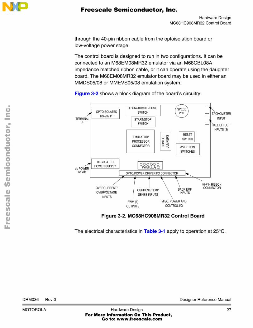
The control board is designed to run in two configurations. It can be connected to an M68EM08MR32 emulator via an M68CBL08A impedance matched ribbon cable, or it can operate using the daughter board. The M68EM08MR32 emulator board may be used in either an MMDS05/08 or MMEVS05/08 emulation system.
Figure 3-2 shows a block diagram of the board’s circuitry.
Figure 3-2. MC68HC908MR32 Control Board
The electrical characteristics in Table 3-1 apply to operation at 25°C.
OPTOISOLATEDRS-232 I/F
TERMINAL
dc POWER12 Vdc
REGULATEDPOWER SUPPLY PWM LEDs (6)
FORWARD/REVERSESWITCH
START/STOPSWITCH
SPEEDPOT
EMULATOR/PROCESSORCONNECTOR
RESETSWITCH
(2) OPTIONSWITCHES
OVERCURRENT/OVERVOLTAGE
INPUTS
PWM (6)OUTPUTS
CURRENT/TEMPSENSE INPUTS
MISC. POWER ANDCONTROL I/O
OPTO/POWER DRIVER I/O CONNECTOR
BACK EMFINPUTS
CO
NFI
G.
JUM
PER
S
40-PIN RIBBON CONNECTOR
INPUTTACHOMETER
HALL EFFECTINPUTS (3)
I/F
DRM036 — Rev 0 Designer Reference Manual
MOTOROLA Hardware Design 27 For More Information On This Product,
Go to: www.freescale.com
Hardware Design
F
ree
sca
le S
em
ico
nd
uc
tor,
I
Freescale Semiconductor, Inc.n
c..
.
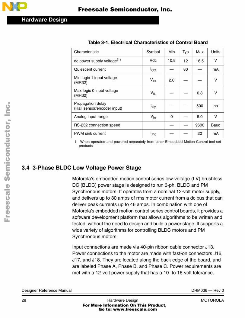
3.4 3-Phase BLDC Low Voltage Power Stage
Motorola’s embedded motion control series low-voltage (LV) brushless DC (BLDC) power stage is designed to run 3-ph. BLDC and PM Synchronous motors. It operates from a nominal 12-volt motor supply, and delivers up to 30 amps of rms motor current from a dc bus that can deliver peak currents up to 46 amps. In combination with one of Motorola’s embedded motion control series control boards, it provides a software development platform that allows algorithms to be written and tested, without the need to design and build a power stage. It supports a wide variety of algorithms for controlling BLDC motors and PM Synchronous motors.
Input connections are made via 40-pin ribbon cable connector J13. Power connections to the motor are made with fast-on connectors J16, J17, and J18. They are located along the back edge of the board, and are labeled Phase A, Phase B, and Phase C. Power requirements are met with a 12-volt power supply that has a 10- to 16-volt tolerance.
Table 3-1. Electrical Characteristics of Control Board
Characteristic Symbol Min Typ Max Units
dc power supply voltage(1)
1. When operated and powered separately from other Embedded Motion Control tool setproducts
Vdc 10.8 12 16.5 V
Quiescent current ICC — 80 — mA
Min logic 1 input voltage (MR32)
VIH 2.0 — — V
Max logic 0 input voltage (MR32)
VIL — — 0.8 V
Propagation delay(Hall sensor/encoder input)
tdly — — 500 ns
Analog input range VIn 0 — 5.0 V
RS-232 connection speed — — 9600 Baud
PWM sink current IPK — — 20 mA
Designer Reference Manual DRM036 — Rev 0
28 Hardware Design MOTOROLA For More Information On This Product,
Go to: www.freescale.com
Hardware Design3-Phase BLDC Low Voltage Power Stage
F
ree
sca
le S
em
ico
nd
uc
tor,
I
Freescale Semiconductor, Inc.n
c..
.
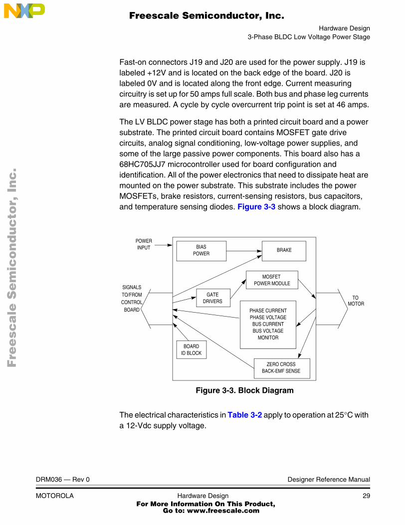
Fast-on connectors J19 and J20 are used for the power supply. J19 is labeled +12V and is located on the back edge of the board. J20 is labeled 0V and is located along the front edge. Current measuring circuitry is set up for 50 amps full scale. Both bus and phase leg currents are measured. A cycle by cycle overcurrent trip point is set at 46 amps.
The LV BLDC power stage has both a printed circuit board and a power substrate. The printed circuit board contains MOSFET gate drive circuits, analog signal conditioning, low-voltage power supplies, and some of the large passive power components. This board also has a 68HC705JJ7 microcontroller used for board configuration and identification. All of the power electronics that need to dissipate heat are mounted on the power substrate. This substrate includes the power MOSFETs, brake resistors, current-sensing resistors, bus capacitors, and temperature sensing diodes. Figure 3-3 shows a block diagram.
Figure 3-3. Block Diagram
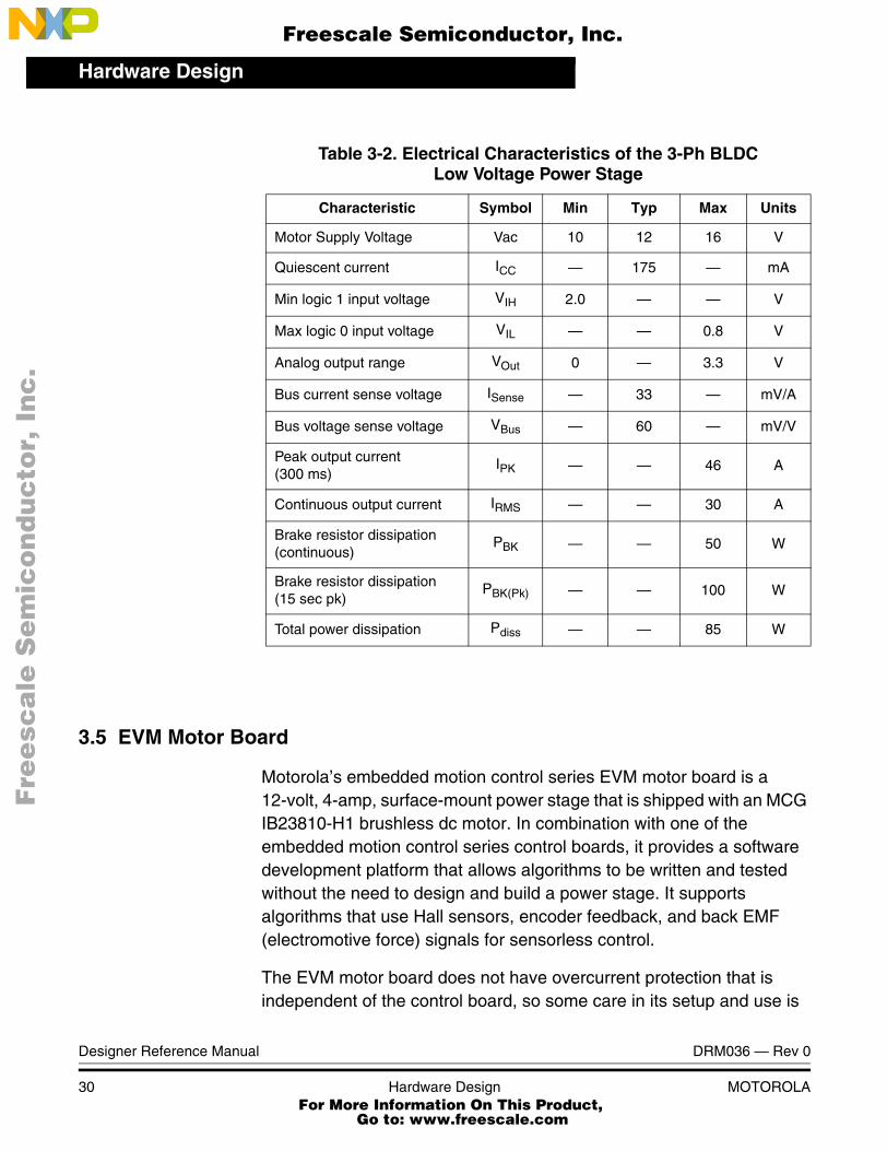
The electrical characteristics in Table 3-2 apply to operation at 25°C with a 12-Vdc supply voltage.
POWERINPUT BIAS
POWERBRAKE
MOSFET
GATE
PHASE CURRENTPHASE VOLTAGE
BUS CURRENTBUS VOLTAGE
MONITOR
ZERO CROSSBACK-EMF SENSE
BOARDID BLOCK
SIGNALSTO/FROMCONTROL
BOARD
POWER MODULE
DRIVERS MOTORTO
DRM036 — Rev 0 Designer Reference Manual
MOTOROLA Hardware Design 29 For More Information On This Product,
Go to: www.freescale.com
Hardware Design
F
ree
sca
le S
em
ico
nd
uc
tor,
I
Freescale Semiconductor, Inc.n
c..
.
3.5 EVM Motor Board
Motorola’s embedded motion control series EVM motor board is a 12-volt, 4-amp, surface-mount power stage that is shipped with an MCG IB23810-H1 brushless dc motor. In combination with one of the embedded motion control series control boards, it provides a software development platform that allows algorithms to be written and tested without the need to design and build a power stage. It supports algorithms that use Hall sensors, encoder feedback, and back EMF (electromotive force) signals for sensorless control.
The EVM motor board does not have overcurrent protection that is independent of the control board, so some care in its setup and use is
Table 3-2. Electrical Characteristics of the 3-Ph BLDCLow Voltage Power Stage
Characteristic Symbol Min Typ Max Units
Motor Supply Voltage Vac 10 12 16 V
Quiescent current ICC — 175 — mA
Min logic 1 input voltage VIH 2.0 — — V
Max logic 0 input voltage VIL — — 0.8 V
Analog output range VOut 0 — 3.3 V
Bus current sense voltage ISense — 33 — mV/A
Bus voltage sense voltage VBus — 60 — mV/V
Peak output current(300 ms)
IPK — — 46 A
Continuous output current IRMS — — 30 A
Brake resistor dissipation (continuous)
PBK — — 50 W
Brake resistor dissipation (15 sec pk)
PBK(Pk) — — 100 W
Total power dissipation Pdiss — — 85 W
Designer Reference Manual DRM036 — Rev 0
30 Hardware Design MOTOROLA For More Information On This Product,
Go to: www.freescale.com
Hardware DesignEVM Motor Board
F
ree
sca
le S
em
ico
nd
uc
tor,
I
Freescale Semiconductor, Inc.n
c..
.
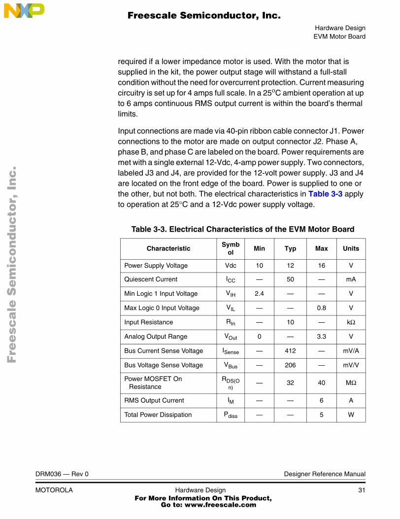
required if a lower impedance motor is used. With the motor that is supplied in the kit, the power output stage will withstand a full-stall condition without the need for overcurrent protection. Current measuring circuitry is set up for 4 amps full scale. In a 25οC ambient operation at up to 6 amps continuous RMS output current is within the board’s thermal limits.
Input connections are made via 40-pin ribbon cable connector J1. Power connections to the motor are made on output connector J2. Phase A, phase B, and phase C are labeled on the board. Power requirements are met with a single external 12-Vdc, 4-amp power supply. Two connectors, labeled J3 and J4, are provided for the 12-volt power supply. J3 and J4 are located on the front edge of the board. Power is supplied to one or the other, but not both. The electrical characteristics in Table 3-3 apply to operation at 25°C and a 12-Vdc power supply voltage.
Table 3-3. Electrical Characteristics of the EVM Motor Board
CharacteristicSymb
olMin Typ Max Units
Power Supply Voltage Vdc 10 12 16 V
Quiescent Current ICC — 50 — mA
Min Logic 1 Input Voltage VIH 2.4 — — V
Max Logic 0 Input Voltage VIL — — 0.8 V
Input Resistance RIn — 10 — kΩ
Analog Output Range VOut 0 — 3.3 V
Bus Current Sense Voltage ISense — 412 — mV/A
Bus Voltage Sense Voltage VBus — 206 — mV/V
Power MOSFET On Resistance
RDS(On)
— 32 40 MΩ
RMS Output Current IM — — 6 A
Total Power Dissipation Pdiss — — 5 W
DRM036 — Rev 0 Designer Reference Manual
MOTOROLA Hardware Design 31 For More Information On This Product,
Go to: www.freescale.com
Hardware Design
F
ree
sca
le S
em
ico
nd
uc
tor,
I
Freescale Semiconductor, Inc.n
c..
.
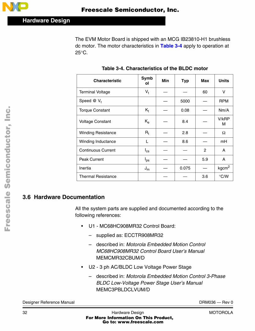
The EVM Motor Board is shipped with an MCG IB23810-H1 brushless dc motor. The motor characteristics in Table 3-4 apply to operation at 25°C.
3.6 Hardware Documentation
All the system parts are supplied and documented according to the following references:
• U1 - MC68HC908MR32 Control Board:
– supplied as: ECCTR908MR32
– described in: Motorola Embedded Motion Control MC68HC908MR32 Control Board User’s Manual MEMCMR32CBUM/D
• U2 - 3 ph AC/BLDC Low Voltage Power Stage
– described in: Motorola Embedded Motion Control 3-Phase BLDC Low-Voltage Power Stage User’s Manual MEMC3PBLDCLVUM/D
Table 3-4. Characteristics of the BLDC motor
CharacteristicSymb
olMin Typ Max Units
Terminal Voltage Vt — — 60 V
Speed @ Vt — 5000 — RPM
Torque Constant Kt — 0.08 — Nm/A
Voltage Constant Ke — 8.4 —V/kRP
M
Winding Resistance Rt — 2.8 — Ω
Winding Inductance L — 8.6 — mH
Continuous Current Ics — — 2 A
Peak Current Ips — — 5.9 A
Inertia Jm — 0.075 — kgcm2
Thermal Resistance — — 3.6 °C/W
Designer Reference Manual DRM036 — Rev 0
32 Hardware Design MOTOROLA For More Information On This Product,
Go to: www.freescale.com

Hardware DesignHardware Documentation
F
ree
sca
le S
em
ico
nd
uc
tor,
I
Freescale Semiconductor, Inc.n
c..
.
• or - Evaluation Motor Board
– described in: Motorola Embedded Motion Control Evaluation Motor Board User’s Manual
Detailed descriptions of individual boards can be found in comprehensive User’s Manuals belonging to each board. The manuals are available on the Motorola web. The User’s Manual incorporates the schematic of the board, description of individual function blocks and a bill of materials. An individual board can be ordered from Motorola as a standard product.
DRM036 — Rev 0 Designer Reference Manual
MOTOROLA Hardware Design 33 For More Information On This Product,
Go to: www.freescale.com

Hardware Design
F
ree
sca
le S
em
ico
nd
uc
tor,
I
Freescale Semiconductor, Inc.n
c..
.
Designer Reference Manual DRM036 — Rev 0
34 Hardware Design MOTOROLA For More Information On This Product,
Go to: www.freescale.com
F
ree
sca
le S
em
ico
nd
uc
tor,
IFreescale Semiconductor, Inc.
nc
...
Designer Reference Manual — Sine Voltage Powered 3-ph PMS Motor
Section 4. Software Design
4.1 Contents
4.2 Software Design . . . . . . . . . . . . . . . . . . . . . . . . . . . . . . . . . . . .35
4.3 Software Data Flow . . . . . . . . . . . . . . . . . . . . . . . . . . . . . . . . .35
4.4 Software Processes . . . . . . . . . . . . . . . . . . . . . . . . . . . . . . . . .37
4.5 PC Master Software (Remote) Operating Mode. . . . . . . . . . . .45
4.2 Software Design
This section describes the design process of control algorithm, and of the software blocks implemented in the drive.
4.3 Software Data Flow
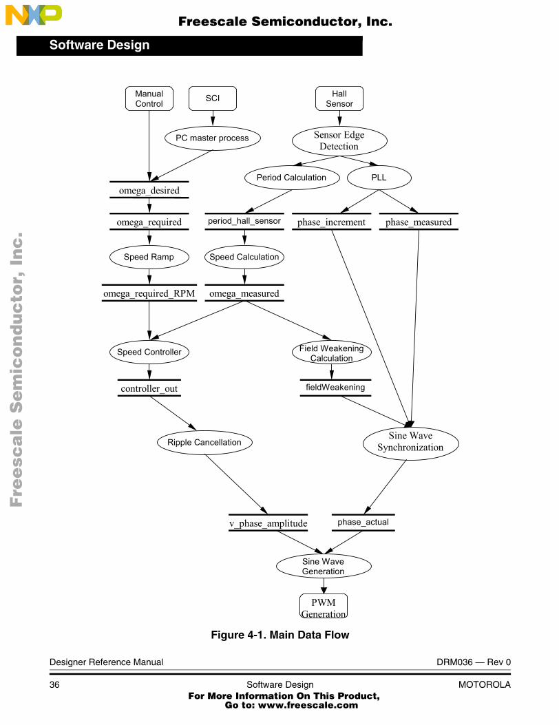
The control algorithm of closed loop drive for the sine voltage powered 3-phase PMS motor with Hall sensors is described in Figure 4-1. The inputs to the algorithm are desired omega from speed pot (Manual Control), or from remote control interface (SCI) and Hall sensor signals (Hall Sensors). The output is a three phase PWM signal (PWM Generation).
DRM036 — Rev 0 Designer Reference Manual
MOTOROLA Software Design 35 For More Information On This Product,
Go to: www.freescale.com
Software Design
F
ree
sca
le S
em
ico
nd
uc
tor,
I
Freescale Semiconductor, Inc.n
c..
.
Figure 4-1. Main Data Flow
PC master process Sensor Edge Detection
SCI
Period Calculation PLL
fieldWeakening
phase_measured phase_increment
Sine Wave Synchronization
phase_actual
period_hall_sensor
Speed Ramp
omega_measured
omega_desired
omega_required
Speed Calculation
omega_required_RPM
Speed Controller
Ripple Cancellation
v_phase_amplitude
Sine Wave Generation
Manual Control
Hall Sensor
Field Weakening Calculation
controller_out
PWM Generation
Designer Reference Manual DRM036 — Rev 0
36 Software Design MOTOROLA For More Information On This Product,
Go to: www.freescale.com
Software DesignSoftware Processes
F
ree
sca
le S
em
ico
nd
uc
tor,
I
Freescale Semiconductor, Inc.n
c..
.
4.4 Software Processes
4.4.1 PC Master Process
A small program is resident in the MR32 that communicates with the PC master software running on the PC. It controls data exchange between the application and the Serial Communication Interface (SCI). The module enables read and write to the CPU RAM and reading the whole CPU memory. It provides a remote control interface to the application. For control actions provided see section 4.5 PC Master Software (Remote) Operating Mode.
4.4.2 Sensor Edge Detection
Each incoming edge on the signal from Hall sensors causes the saving of the actual timer value and setting of the capture flag. The flag is recognized in the following PWM reload, and it starts a task which is divided between two PWM reloads interrupts. In the first interrupt the sine wave is synchronized, and the period of the hall sensor signal is calculated. In the following PWM reload interrupt, the “phase_increment” is calculated.
4.4.3 Period Calculation
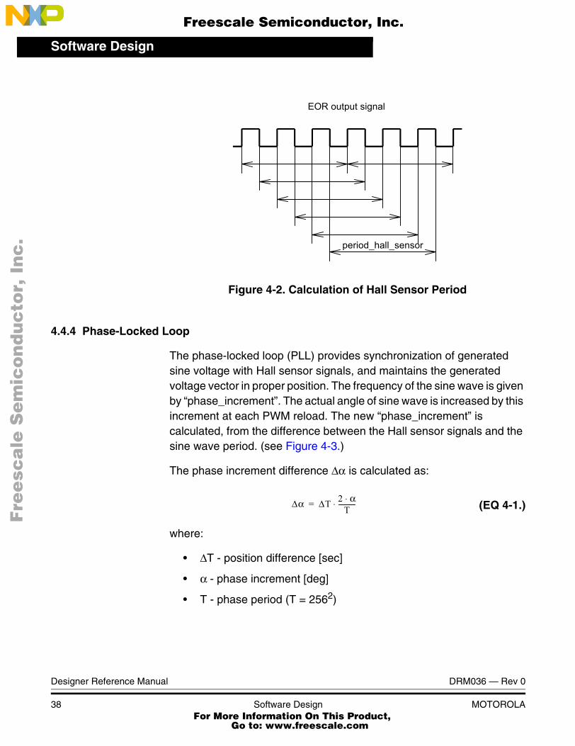
The principle of period calculation is shown in Figure 4-2. The motor used has two pole-pairs and three Hall sensors. To eliminate the difference between the Hall sensors, the edges from same sensor are used for period calculation. The period is calculated on each EOR signal edge, but for period calculation the difference between six successive edges on EOR signal is taken.
DRM036 — Rev 0 Designer Reference Manual
MOTOROLA Software Design 37 For More Information On This Product,
Go to: www.freescale.com
Software Design
F
ree
sca
le S
em
ico
nd
uc
tor,
I
Freescale Semiconductor, Inc.n
c..
.
Figure 4-2. Calculation of Hall Sensor Period
4.4.4 Phase-Locked Loop
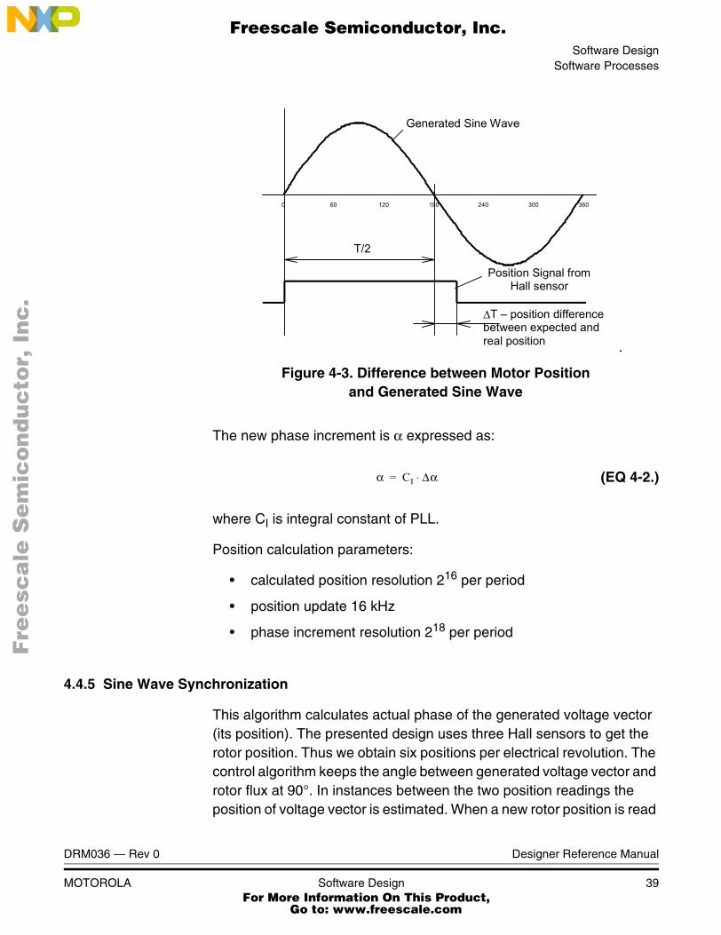
The phase-locked loop (PLL) provides synchronization of generated sine voltage with Hall sensor signals, and maintains the generated voltage vector in proper position. The frequency of the sine wave is given by “phase_increment”. The actual angle of sine wave is increased by this increment at each PWM reload. The new “phase_increment” is calculated, from the difference between the Hall sensor signals and the sine wave period. (see Figure 4-3.)
The phase increment difference ∆α is calculated as:
(EQ 4-1.)
where:
• ∆T - position difference [sec]
• α - phase increment [deg]
• T - phase period (T = 2562)
period_hall_sensor
EOR output signal
∆α ∆T 2 α⋅T
-----------⋅=
Designer Reference Manual DRM036 — Rev 0
38 Software Design MOTOROLA For More Information On This Product,
Go to: www.freescale.com
Software DesignSoftware Processes
F
ree
sca
le S
em
ico
nd
uc
tor,
I
Freescale Semiconductor, Inc.n
c..
.
.
Figure 4-3. Difference between Motor Positionand Generated Sine Wave
The new phase increment is α expressed as:
(EQ 4-2.)
where CI is integral constant of PLL.
Position calculation parameters:
• calculated position resolution 216 per period
• position update 16 kHz
• phase increment resolution 218 per period
4.4.5 Sine Wave Synchronization
This algorithm calculates actual phase of the generated voltage vector (its position). The presented design uses three Hall sensors to get the rotor position. Thus we obtain six positions per electrical revolution. The control algorithm keeps the angle between generated voltage vector and rotor flux at 90°. In instances between the two position readings the position of voltage vector is estimated. When a new rotor position is read
0 60 120 180 240 300 360
∆T position differencebetween expected and real position
T/2
Generated Sine Wave
Position Signal from Hall sensor
α CI ∆α⋅=
DRM036 — Rev 0 Designer Reference Manual
MOTOROLA Software Design 39 For More Information On This Product,
Go to: www.freescale.com
Software Design
F
ree
sca
le S
em
ico
nd
uc
tor,
I
Freescale Semiconductor, Inc.n
c..
.
from Hall sensors the position of the generated voltage vector is synchronized by means of PLL algorithm (see 4.4.4 Phase-Locked Loop). The designed application is even able to perform high-efficient control of a motor using only one Hall sensor for position sensing.
4.4.6 Speed Ramp
The Speed ramp decreases the rate of required speed variation.
4.4.7 Speed Calculation
The speed ωm (EQ 4-3.) is calculated every 5ms in the timer overflow interrupt.
(EQ 4-3.)
where
• Cω is a constant representing the omega scale and the number of pole pairs.
• Th is the Hall sensor period
4.4.8 Speed Controller
The scaled PI controller is used for the speed closed loop. The controller is called every 5ms. The controller constants were tuned experimentally. The frequency of speed update depends on actual motor speed (according to the rate of incoming edges for Hall sensors). To achieve the best results the speed controller constants are recalculated according to the sensed speed. The controller constants are calculated according to (EQ 4-4.) and (EQ 4-5.). The sensed speed can be updated only when the edge on the Hall sensor signal is detected. The long
ωmCω
Th-------=
Designer Reference Manual DRM036 — Rev 0
40 Software Design MOTOROLA For More Information On This Product,
Go to: www.freescale.com
Software DesignSoftware Processes
F
ree
sca
le S
em
ico
nd
uc
tor,
I
Freescale Semiconductor, Inc.n
c..
.
period between the Hall sensor signal edges al low speed could cause speed fluctuations of the motor.
(EQ 4-4.)
(EQ 4-5.)
where
• CI is integral constant
• CP is proportional constant
• C1,C2,C3,C4 are constants tuned experimentally
4.4.9 Voltage Ripple Cancellation
The voltage ripple cancellation recalculates the absolute required voltage into a relative voltage, so that output voltage amplitude does not depend on the dc-bus voltage.
(EQ 4-6.)
where:
• Ureq is absolute voltage required by speed controller [V]
• Urel is relative voltage going to sine wave generator [-]
• UDC is dc-bus voltage [V]
The purpose of the function is to ensure that a jump in dc-bus voltage does not cause transient speed deviation.
4.4.10 Field Weakening Calculation
A field weakening of the motor may be required to extend the full speed range. The PMS motor can be field weakened by increasing the angle
CI C1 C2 ωm⋅+=
CP C3 C4 ωm⋅+=
UrelUreq
UDC----------=
DRM036 — Rev 0 Designer Reference Manual
MOTOROLA Software Design 41 For More Information On This Product,
Go to: www.freescale.com
Software Design
F
ree
sca
le S
em
ico
nd
uc
tor,
I
Freescale Semiconductor, Inc.n
c..
.
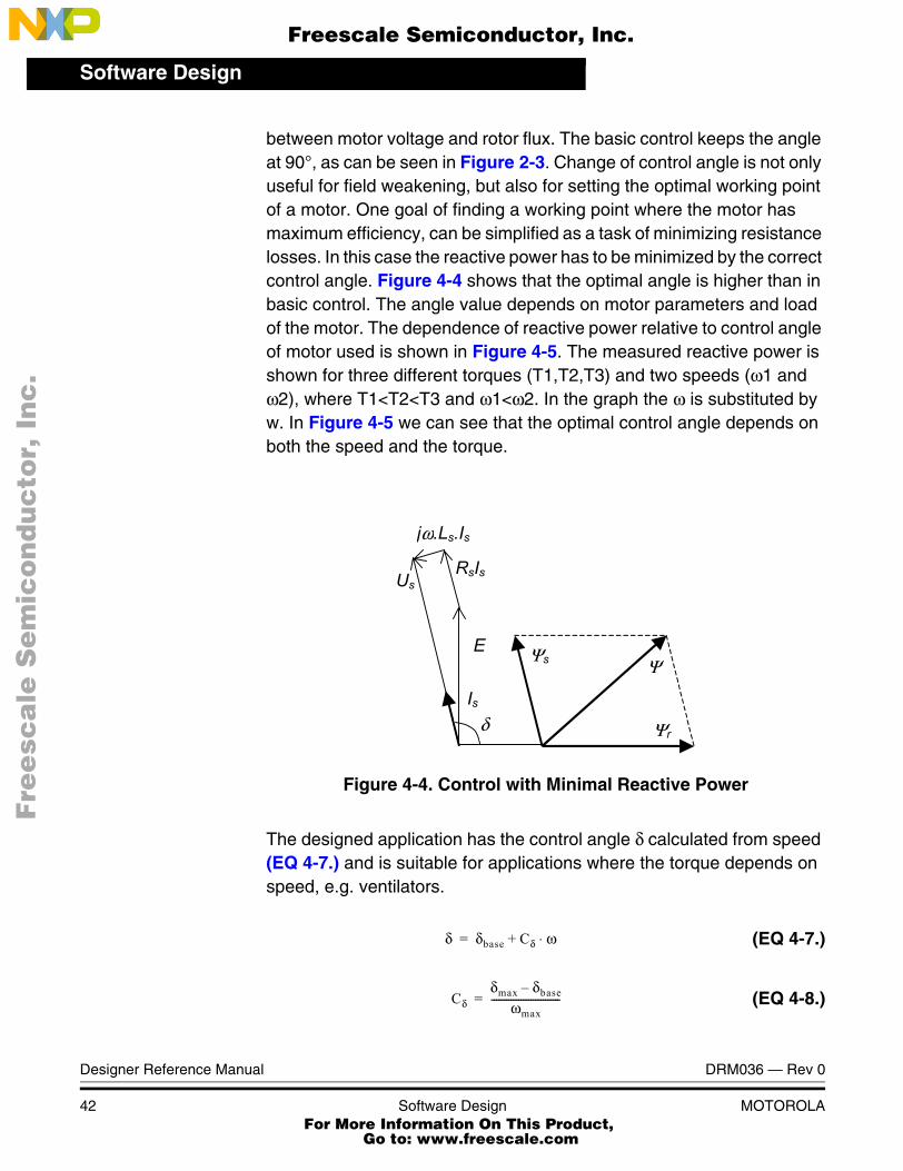
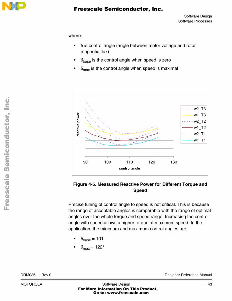
between motor voltage and rotor flux. The basic control keeps the angle at 90°, as can be seen in Figure 2-3. Change of control angle is not only useful for field weakening, but also for setting the optimal working point of a motor. One goal of finding a working point where the motor has maximum efficiency, can be simplified as a task of minimizing resistance losses. In this case the reactive power has to be minimized by the correct control angle. Figure 4-4 shows that the optimal angle is higher than in basic control. The angle value depends on motor parameters and load of the motor. The dependence of reactive power relative to control angle of motor used is shown in Figure 4-5. The measured reactive power is shown for three different torques (T1,T2,T3) and two speeds (ω1 and ω2), where T1<T2<T3 and ω1<ω2. In the graph the ω is substituted by w. In Figure 4-5 we can see that the optimal control angle depends on both the speed and the torque.
Figure 4-4. Control with Minimal Reactive Power
The designed application has the control angle δ calculated from speed (EQ 4-7.) and is suitable for applications where the torque depends on speed, e.g. ventilators.
(EQ 4-7.)
(EQ 4-8.)
Us
jω.Ls.Is
Ψr
Ψs Ψ
RsIs
E
Is δ
δ δbase Cδ ω⋅+=
Cδδmax δbase
ωmax----------------------------=
Designer Reference Manual DRM036 — Rev 0
42 Software Design MOTOROLA For More Information On This Product,
Go to: www.freescale.com
Software DesignSoftware Processes
F
ree
sca
le S
em
ico
nd
uc
tor,
I
Freescale Semiconductor, Inc.n
c..
.
where:
• δ is control angle (angle between motor voltage and rotor magnetic flux)
• δbase is the control angle when speed is zero
• δmax is the control angle when speed is maximal
Figure 4-5. Measured Reactive Power for Different Torque and Speed
Precise tuning of control angle to speed is not critical. This is because the range of acceptable angles is comparable with the range of optimal angles over the whole torque and speed range. Increasing the control angle with speed allows a higher torque at maximum speed. In the application, the minimum and maximum control angles are:
• δbase = 101°
• δmax = 122°
90 100 110 120 130control angle
reac
tive
pow
er
w2_T3w1_T3w2_T2w1_T2w2_T1w1_T1
DRM036 — Rev 0 Designer Reference Manual
MOTOROLA Software Design 43 For More Information On This Product,
Go to: www.freescale.com
Software Design
F
ree
sca
le S
em
ico
nd
uc
tor,
I
Freescale Semiconductor, Inc.n
c..
.
4.4.11 Sine Wave Generation
The sine wave generation is calculated each PWM reload interrupt, which is every 64us. The function
sin3p3hPIxLUT (UByte u_phase_amplitude, SWord16 phase_actual);
gets the sine of the actual phase for all three phases from the table, and multiplies it by the voltage amplitude. Resolution of the sine is 1024 points per period and, 256 points per amplitude. The function is written in assembly to minimize execution time. The execution time is about 20us.
4.4.12 Over Voltage Limitation
Over-voltage limitation protects the power stage during deceleration. If the dc-bus voltage exceeds maximum voltage limit the deceleration of the motor is interrupted. The required speed is increased to keep the dc-bus voltage under the limiting value. When the dc-bus voltage is stabilized the deceleration of motor continues.
4.4.13 CPU Reset to Turning Motor
If the CPU is reset while the motor is running, the initialization routine recognizes the running motor from the Hall sensor signals. Then the speed of motor is calculated, and PLL is synchronized with the Hall sensor signals. The voltage amplitude is estimated from the measured speed, which helps to switch-on PWM without torque surge. CPU reset always switches the application to manual control, even if the application before reset was controlled by PC master software.
NOTE: The application source code includes also “Torque Limitation” algorithm. This feature is disabled in this application. If the limitation of motor torque is required it may be added to the user application. The torque limitation constants used in the algorithm depend on particular motor parameters, therefore the user has to define his motor specific parameters. For more details on “Torque Limitation” algorithm see AN 2357/D “Sine Voltage Powered 3-Phase Permanent Magnet Motor with Hall Sensor”, Motorola, 2002.
Designer Reference Manual DRM036 — Rev 0
44 Software Design MOTOROLA For More Information On This Product,
Go to: www.freescale.com
Software DesignPC Master Software (Remote) Operating Mode
F
ree
sca
le S
em
ico
nd
uc
tor,
I
Freescale Semiconductor, Inc.n
c..
.
4.5 PC Master Software (Remote) Operating Mode
The drive is controlled remotely from a PC via an RS-232 physical interface. The manual control is ignored and all required values are controlled from PC.
The actions controlled in PC master operating mode are:
• Start/Stop control
• Motor speed setpoint
• Close Loop/Open Loop operation
PC master software displays the following information on a control page:
• Speed
• DC-Bus voltage
• Drive status
• Close Loop/Open Loop operation status
• Application mode (manual/remote control)
The other variables can be viewed in the variables section.
DRM036 — Rev 0 Designer Reference Manual
MOTOROLA Software Design 45 For More Information On This Product,
Go to: www.freescale.com

Software Design
F
ree
sca
le S
em
ico
nd
uc
tor,
I
Freescale Semiconductor, Inc.n
c..
.
Designer Reference Manual DRM036 — Rev 0
46 Software Design MOTOROLA For More Information On This Product,
Go to: www.freescale.com
F
ree
sca
le S
em
ico
nd
uc
tor,
IFreescale Semiconductor, Inc.
nc
...
Designer Reference Manual — Sine Voltage Powered 3-ph PMS Motor
Section 5. Application Setup
5.1 Contents
5.2 Warning . . . . . . . . . . . . . . . . . . . . . . . . . . . . . . . . . . . . . . . . . .47
5.3 Hardware Setup . . . . . . . . . . . . . . . . . . . . . . . . . . . . . . . . . . . .47
5.4 Software Setup . . . . . . . . . . . . . . . . . . . . . . . . . . . . . . . . . . . . .50
5.5 Executing the Application . . . . . . . . . . . . . . . . . . . . . . . . . . . . .51
5.2 Warning
The application includes a rotating machine and power transistors. Both can reach temperatures hot enough to cause burns. To facilitate safe operation, 12-volt input power should come from a dc laboratory power supply that is current limited.
The user should be aware that:
Before moving scope probes, making connections, etc., it is generally advisable to power down the 12-volt supply.
Operation in lab setups that have grounded tables and/or chairs should be avoided.
Wearing safety glasses, avoiding ties and jewelry, using shields, and operation by personnel trained in power electronics lab techniques are also advisable.
5.3 Hardware Setup
The motor control system is designed to drive the 3-phase PMS motor in a speed closed loop using a 68HC908MR32 microcontroller. The
DRM036 — Rev 0 Designer Reference Manual
MOTOROLA Application Setup 47 For More Information On This Product,
Go to: www.freescale.com
Application Setup
F
ree
sca
le S
em
ico
nd
uc
tor,
I
Freescale Semiconductor, Inc.n
c..
.
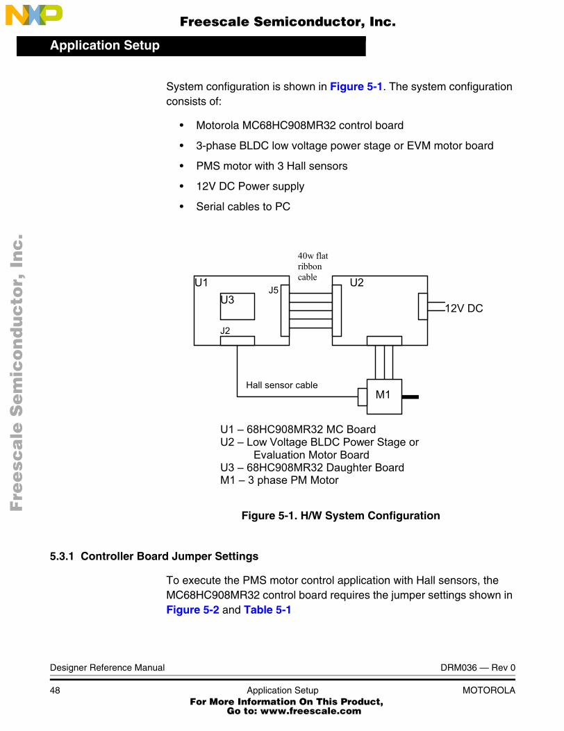
System configuration is shown in Figure 5-1. The system configuration consists of:
• Motorola MC68HC908MR32 control board
• 3-phase BLDC low voltage power stage or EVM motor board
• PMS motor with 3 Hall sensors
• 12V DC Power supply
• Serial cables to PC
Figure 5-1. H/W System Configuration
5.3.1 Controller Board Jumper Settings
To execute the PMS motor control application with Hall sensors, the MC68HC908MR32 control board requires the jumper settings shown in Figure 5-2 and Table 5-1
U1 68HC908MR32 MC Board U2 Low Voltage BLDC Power Stage or Evaluation Motor Board U3 68HC908MR32 Daughter Board M1 3 phase PM Motor
M1
U3 U2 U1
Hall sensor cable
J2
J5
12V DC
40w flat ribbon cable
Designer Reference Manual DRM036 — Rev 0
48 Application Setup MOTOROLA For More Information On This Product,
Go to: www.freescale.com
Application SetupHardware Setup
F
ree
sca
le S
em
ico
nd
uc
tor,
I
Freescale Semiconductor, Inc.n
c..
.
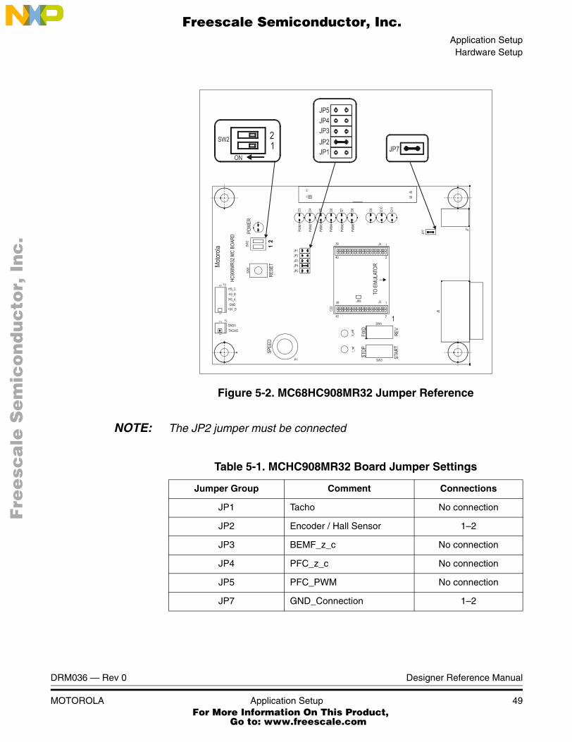
Figure 5-2. MC68HC908MR32 Jumper Reference
NOTE: The JP2 jumper must be connected
Table 5-1. MCHC908MR32 Board Jumper Settings
Jumper Group Comment Connections
JP1 Tacho No connection
JP2 Encoder / Hall Sensor 1–2
JP3 BEMF_z_c No connection
JP4 PFC_z_c No connection
JP5 PFC_PWM No connection
JP7 GND_Connection 1–2
DRM036 — Rev 0 Designer Reference Manual
MOTOROLA Application Setup 49 For More Information On This Product,
Go to: www.freescale.com
Application Setup
F
ree
sca
le S
em
ico
nd
uc
tor,
I
Freescale Semiconductor, Inc.n
c..
.
5.4 Software Setup
5.4.1 Required Software Tools
The application requires then following software development tools:
• Metrowerks1CodeWarrior®2 for MC68HC08 microcontrollers version 1.2 or later.
• PC master software version 1.2.0.11 or later
5.4.2 Application Files
The application files are distributed in compressed zip-file: 3ph_pm_sin_3hs_sa.zip. Uncompress the files to the folder on you hard drive. The PMS motor control application with Hall sensors is composed of the following files:
• 3ph_pm_sin_3hs_sa.mcp, application project file
• sources\3ph_pm_sin_3hs.c, main program
• sources\3ph_pm_sin_3hs.h, main program header file
• sources\appconfig.h, application configuration file for static periphery configuration
• prms\hc908mr32.prm, linker parameters file
• pcmaster\3ph_pm_sin_3hs.pmp, PC master software file
Besides the application specific files listed above the application is distributed with peripheral drivers and algorithms placed in following folders:
• config peripheral start-up code
• drivers and drivers\highlevel - peripheral and high-level drivers
1. Metrowerks® and the Metrowerks logo are registered trademarks of Metrowerks, Inc., a wholly owned subsidiary of Motorola, Inc.
2. CodeWarrior® is a registered trademark of Metrowerks, Inc., a wholly owned subsidiary of Motorola, Inc.
Designer Reference Manual DRM036 — Rev 0
50 Application Setup MOTOROLA For More Information On This Product,
Go to: www.freescale.com
Application SetupExecuting the Application
F
ree
sca
le S
em
ico
nd
uc
tor,
I
Freescale Semiconductor, Inc.n
c..
.
• algorithms - general motor control algorithms
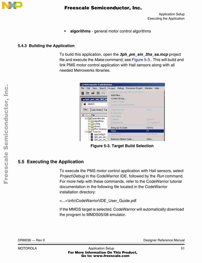
5.4.3 Building the Application
To build this application, open the 3ph_pm_sin_3hs_sa.mcp project file and execute the Make command; see Figure 5-3.. This will build and link PMS motor control application with Hall sensors along with all needed Metrowerks libraries.
Figure 5-3. Target Build Selection
5.5 Executing the Application
To execute the PMS motor control application with Hall sensors, select Project\Debug in the CodeWarrior IDE, followed by the Run command. For more help with these commands, refer to the CodeWarrior tutorial documentation in the following file located in the CodeWarrior installation directory:
<...>\info\CodeWarrior\IDE_User_Guide.pdf
If the MMDS target is selected, CodeWarrior will automatically download the program to MMDS05/08 emulator.
DRM036 — Rev 0 Designer Reference Manual
MOTOROLA Application Setup 51 For More Information On This Product,
Go to: www.freescale.com
Application Setup
F
ree
sca
le S
em
ico
nd
uc
tor,
I
Freescale Semiconductor, Inc.n
c..
.
5.5.1 Application Modes
This PMS motor control application with Hall sensors can operate in two modes:
1. Manual operating mode
2. PC master software (remote) operating mode
5.5.1.1 Manual Operating Mode
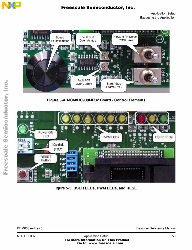
Refer to MC68HC908MR32 control board shown in Figure 5-4 and Figure 5-5 for this description:
• START/STOP switch (SW3) - start/stop of the motor
• SPEED potentiometer (P1) - set motor speed
• DIP switch SW2 functions:
– 1 - open/closed loop operation (ON - closed loop on)
– 2 - N/A
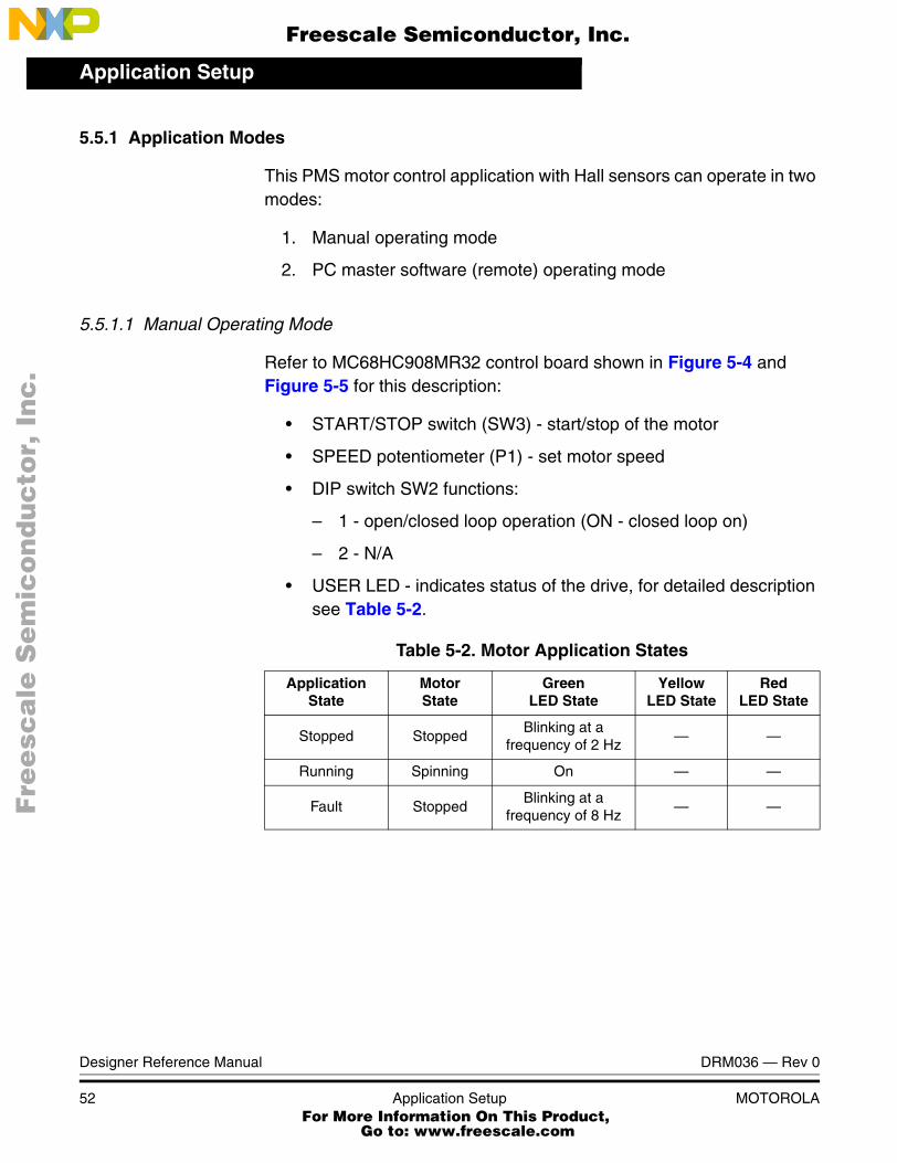
• USER LED - indicates status of the drive, for detailed description see Table 5-2.
Table 5-2. Motor Application States
ApplicationState
MotorState
GreenLED State
YellowLED State
RedLED State
Stopped StoppedBlinking at a
frequency of 2 Hz— —
Running Spinning On — —
Fault StoppedBlinking at a
frequency of 8 Hz— —
Designer Reference Manual DRM036 — Rev 0
52 Application Setup MOTOROLA For More Information On This Product,
Go to: www.freescale.com
Application SetupExecuting the Application
F
ree
sca
le S
em
ico
nd
uc
tor,
I
Freescale Semiconductor, Inc.n
c..
.
Figure 5-4. MC68HC908MR32 Board - Control Elements
Figure 5-5. USER LEDs, PWM LEDs, and RESET
Speedpotentiometer
Forward / Reverseswitch SW4
Start / Stopswitch SW3
Fault POTOver-Voltage
Fault POTOver-Current
SpeedPotentiometer
Fault POTOver-Voltage
Forward / ReverseSwitch SW4
Fault POTOver-Current Start / Stop
Switch SW3
DRM036 — Rev 0 Designer Reference Manual
MOTOROLA Application Setup 53 For More Information On This Product,
Go to: www.freescale.com
Application Setup
F
ree
sca
le S
em
ico
nd
uc
tor,
I
Freescale Semiconductor, Inc.n
c..
.
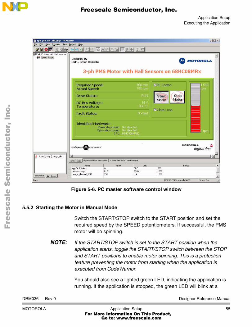
5.5.1.2 PC Master (Remote) Operating Mode
The drive is controlled remotely from a PC via an RS-232 physical interface. The actions controlled in PC master operating mode are:
• Start/Stop control
• Motor speed setpoint
• Close Loop/Open Loop operation
The PC master software displays the following information:
• Speed
• DC-Bus voltage
• Drive status
• Close Loop/Open Loop operation status
• Application mode (manual/remote control)
Project files for PC master software are located in:
PC master software file
..\pcmaster\3ph_pm_sin_3hs.pmp
To start the PC master software’s window application
3ph_pm_sin_3hs.pmp
NOTE: If the PC master project (.pmp file) is unable to control the application, it is possible the wrong symbol file(.elf file) has been selected. The PC master software uses the.elf file to determine addresses for global variables being monitored. Once the PC master project has been launched, this option may be selected in the PC master window under "Project/Select Symbol File”. To reload the symbol file select "Project/Reload Symbol File”
The PC master software control window is shown in Figure 5-6.
Designer Reference Manual DRM036 — Rev 0
54 Application Setup MOTOROLA For More Information On This Product,
Go to: www.freescale.com
Application SetupExecuting the Application
F
ree
sca
le S
em
ico
nd
uc
tor,
I
Freescale Semiconductor, Inc.n
c..
.
Figure 5-6. PC master software control window
5.5.2 Starting the Motor in Manual Mode
Switch the START/STOP switch to the START position and set the required speed by the SPEED potentiometers. If successful, the PMS motor will be spinning.
NOTE: If the START/STOP switch is set to the START position when the application starts, toggle the START/STOP switch between the STOP and START positions to enable motor spinning. This is a protection feature preventing the motor from starting when the application is executed from CodeWarrior.
You should also see a lighted green LED, indicating the application is running. If the application is stopped, the green LED will blink at a
DRM036 — Rev 0 Designer Reference Manual
MOTOROLA Application Setup 55 For More Information On This Product,
Go to: www.freescale.com

Application Setup
F
ree
sca
le S
em
ico
nd
uc
tor,
I
Freescale Semiconductor, Inc.n
c..
.
frequency of 2 Hz. If a fault occurs, the green LED will blink at a frequency of 8 Hz.
NOTE: In manual control mode, the SW2-1 switch on the CPU board (see Figure 5-5) determines close/open loop (close loop is at position On).
5.5.3 Starting the Motor in Remote Control Mode (using PC Master)
To set the PC master control, perform the following steps:
1. The RUN/STOP switch must be in the STOP position
2. Check the PC master mode on the PC master control page
3. Start the motor by pressing the START PC Master Push Button
4. Set the speed with the bar graph
5. Stop the motor by pressing the STOP PC Master Push Button
Designer Reference Manual DRM036 — Rev 0
56 Application Setup MOTOROLA For More Information On This Product,
Go to: www.freescale.com
F
ree
sca
le S
em
ico
nd
uc
tor,
IFreescale Semiconductor, Inc.
nc
...
Designer Reference Manual — Sine Voltage Powered 3-ph PMS Motor
Appendix A. References
1. Electronically Commutated Motors for Fan Applications, A. Lelkes, PCIM 2002.
2. Design of Brushless Permanent-magnet Motors, J.R. Hendershot and T.J.E. Miller, Magna Physics Publishing and Clarendon Press, 1994
3. AN 2357/D Sine Voltage Powered 3-Phase Permanent Magnet Motor with Hall Sensor, Motorola, 2002
4. 68HC908MR32 User’s Manual, Motorola, Inc. (2001), (order #:MC68HC908MR32/D)
5. Motorola Embedded Motion Control MC68HC908MR32 Control Board User’s Manual, Motorola, 2000(order #:MEMCEVMBUM/D)
6. Motorola Embedded Motion Control 3-Phase BLDC Low-Voltage Power Stage User’s Manual, Motorola, 2000 (order #: MEMC3PBLDCLVUM/D)
7. Motorola Embedded Motion Control Evaluation Motor Board User’s Manual, Motorola, 2000(order #:MEMCEVMBUM/D)
8. AN 1917/D 3-Phase Synchronous PM Motor Control with Quadrature Encoder Using DSP56F80x, Motorola, 2002
DRM036 — Rev 0 Designer Reference Manual
MOTOROLA References 57 For More Information On This Product,
Go to: www.freescale.com

References
F
ree
sca
le S
em
ico
nd
uc
tor,
I
Freescale Semiconductor, Inc.n
c..
.
Designer Reference Manual DRM036 — Rev 0
58 References MOTOROLA For More Information On This Product,
Go to: www.freescale.com
F
ree
sca
le S
em
ico
nd
uc
tor,
IFreescale Semiconductor, Inc.
nc
...
Designer Reference Manual — Sine Voltage Powered 3-ph PMS Motor
Appendix B. Glossary
AC — Alternating current.
analogue-to-digital converter (ADC) — The ADC module is an 10-channel, multiplexed-input successive-approximation analog-to-digital converter.
brush — A component transfering electrical power from non-rotational terminals, mounted on the stator, to the rotor
byte — A set of eight bits.
central processor unit (CPU) — The primary functioning unit of any computer system. The CPU controls the execution of instructions.
clear — To change a bit from logic 1 to logic 0; the opposite of set.
commutation — A process providing the creation of a rotation field by switching of power transistor (electronic replacement of brush and commutator)
commutator — A mechanical device alternating DC current in DC commutator motor and providing rotation of DC commutator motor
comparator — A device that compares the magnitude of two inputs. A digital comparator defines the equality or relative differences between two binary numbers.
computer operating properly module (COP) — A counter module that resets the MCU if allowed to overflow.
COP — Computer Operating Properly timer
DC — Direct Current.
DT — see “Dead Time (DT)”
DRM036 — Rev 0 Designer Reference Manual
MOTOROLA Glossary 59 For More Information On This Product,
Go to: www.freescale.com
Glossary
F
ree
sca
le S
em
ico
nd
uc
tor,
I
Freescale Semiconductor, Inc.n
c..
.
Dead Time (DT) — short time that must be inserted between the turning off of one transistor in the inverter half bridge and turning on of the complementary transistor due to the limited switching speed of the transistors.
duty cycle — A ratio of the amount of time the signal is on versus the time it is off. Duty cycle is usually represented by a percentage.
GPIO — General Purpose Input/Output.
Hall Sensors - A position sensor giving six defined events (each 60 electrical degrees) per electrical revolution (for 3-phase motor)
interrupt — A temporary break in the sequential execution of a program to respond to signals from peripheral devices by executing a subroutine.
interrupt request — A signal from a peripheral to the CPU intended to cause the CPU to execute a subroutine.
input/output (I/O) — Input/output interfaces between a computer system and the external world. A CPU reads an input to sense the level of an external signal and writes to an output to change the level on an external signal.
LED — Light Emitting Diode
logic 1 — A voltage level approximately equal to the input power voltage (VDD).
logic 0 — A voltage level approximately equal to the ground voltage (VSS).
MCU — Microcontroller unit. See “microcontroller.”
memory map — A pictorial representation of all memory locations in a computer system.
microcontroller — Microcontroller unit (MCU). A complete computer system, including a CPU, memory, a clock oscillator, and input/output (I/O) on a single integrated circuit.
modulo counter — A counter that can be programmed to count to any number from zero to its maximum possible modulus.
Designer Reference Manual DRM036 — Rev 0
60 Glossary MOTOROLA For More Information On This Product,
Go to: www.freescale.com
Glossary
F
ree
sca
le S
em
ico
nd
uc
tor,
I
Freescale Semiconductor, Inc.n
c..
.
PI controller — Proportional-Integral controller.
peripheral — A circuit not under direct CPU control.
phase-locked loop (PLL) — A clock generator circuit in which a voltage controlled oscillator produces an oscillation which is synchronized to a reference signal.
PM — Permanent Magnet
PMSM - Permanent Magnet Synchronous Motor.
port — A set of wires for communicating with off-chip devices.
program — A set of computer instructions that cause a computer to perform a desired operation or operations.
PWM — Pulse Width Modulation.
PWM period — The time required for one complete cycle of a PWM waveform.
read — To copy the contents of a memory location to the accumulator.
register — A circuit that stores a group of bits.
reset — To force a device to a known condition.
RPM — Revolutions per minute.
SCI — See “serial communication interface module (SCI).”
serial communications interface module (SCI) — A module that supports asynchronous communication.
serial peripheral interface module (SPI) — A module that supports synchronous communication.
set — To change a bit from logic 0 to logic 1; opposite of clear.
software — Instructions and data that control the operation of a microcontroller.
software interrupt (SWI) — An instruction that causes an interrupt and its associated vector fetch.
DRM036 — Rev 0 Designer Reference Manual
MOTOROLA Glossary 61 For More Information On This Product,
Go to: www.freescale.com
Glossary
F
ree
sca
le S
em
ico
nd
uc
tor,
I
Freescale Semiconductor, Inc.n
c..
.
SPI — See “serial peripheral interface module (SPI).”
stack — A portion of RAM reserved for storage of CPU register contents and subroutine return addresses.
subroutine — A sequence of instructions to be used more than once in the course of a program. The last instruction in a subroutine is a return from subroutine (RTS) instruction. At each place in the main program where the subroutine instructions are needed, a jump or branch to subroutine (JSR or BSR) instruction is used to call the subroutine. The CPU leaves the flow of the main program to execute the instructions in the subroutine. When the RTS instruction is executed, the CPU returns to the main program where it left off.
timer — A module used to relate events in a system to a point in time.
variable — A value that changes during the course of program execution.
waveform — A graphical representation in which the amplitude of a wave is plotted against time.
word — A set of two bytes (16 bits).
write — The transfer of a byte of data from the CPU to a memory location.
Designer Reference Manual DRM036 — Rev 0
62 Glossary MOTOROLA For More Information On This Product,
Go to: www.freescale.com

F
ree
sca
le S
em
ico
nd
uc
tor,
I
Freescale Semiconductor, Inc.n
c..
.
For More Information On This Product,
Go to: www.freescale.com
F
ree
sca
le S
em
ico
nd
uc
tor,
I
Freescale Semiconductor, Inc.n
c..
.
HOW TO REACH US:
USA/EUROPE/LOCATIONS NOT LISTED:
Motorola Literature Distribution; P.O. Box 5405, Denver, Colorado 80217 1-303-675-2140 or 1-800-441-2447
JAPAN:
Motorola Japan Ltd.; SPS, Technical Information Center, 3-20-1, Minami-Azabu Minato-ku, Tokyo 106-8573 Japan81-3-3440-3569
ASIA/PACIFIC:
Motorola Semiconductors H.K. Ltd.; Silicon Harbour Centre, 2 Dai King Street, Tai Po Industrial Estate, Tai Po, N.T., Hong Kong852-26668334
TECHNICAL INFORMATION CENTER:
1-800-521-6274
HOME PAGE:
http://motorola.com/semiconductors
Information in this document is provided solely to enable system and software
implementers to use Motorola products. There are no express or implied copyright
licenses granted hereunder to design or fabricate any integrated circuits or
integrated circuits based on the information in this document.
Motorola reserves the right to make changes without further notice to any products
herein. Motorola makes no warranty, representation or guarantee regarding the
suitability of its products for any particular purpose, nor does Motorola assume any
liability arising out of the application or use of any product or circuit, and specifically
disclaims any and all liability, including without limitation consequential or incidental
damages. “Typical” parameters which may be provided in Motorola data sheets
and/or specifications can and do vary in different applications and actual
performance may vary over time. All operating parameters, including “Typicals”
must be validated for each customer application by customer’s technical experts.
Motorola does not convey any license under its patent rights nor the rights of
others. Motorola products are not designed, intended, or authorized for use as
components in systems intended for surgical implant into the body, or other
applications intended to support or sustain life, or for any other application in which
the failure of the Motorola product could create a situation where personal injury or
death may occur. Should Buyer purchase or use Motorola products for any such
unintended or unauthorized application, Buyer shall indemnify and hold Motorola
and its officers, employees, subsidiaries, affiliates, and distributors harmless
against all claims, costs, damages, and expenses, and reasonable attorney fees
arising out of, directly or indirectly, any claim of personal injury or death associated
with such unintended or unauthorized use, even if such claim alleges that Motorola
was negligent regarding the design or manufacture of the part.
Motorola and the Stylized M Logo are registered in the U.S. Patent and Trademark Office. digital dna is a trademark of Motorola, Inc. All other product or service names are the property of their respective owners. Motorola, Inc. is an Equal Opportunity/Affirmative Action Employer.
© Motorola, Inc. 2003
DRM036/D
For More Information On This Product,
Go to: www.freescale.com