Embed Size (px)
Citation preview

TY-05-30 / TY-05-40
User Manual
Page 2Page 2Page 3
Dimensions in Inches Specifications Electronics HardwareAssembly Instructions
Page 3
Contents
Page 4-6

Dimensions in Inches
2
Specifications
12.5 + Stroke Length + Stroke Length
Dynamic Load
TV Maximum Height:Wall Mount Measurements:
Speed at Full Load:
Output Voltage:
Weight:
Overload Protection:Duty Cycle:
IP Grade:Operational Temperature:Certification:Control Options:
30" Stroke = 30" Tall700mm x 500mm
120 VAC 60Hz
30"25.5 lbs
Fused10% (2 minutes on, 18 minutes off)
Built-in, non-adjustable and externally mountingIP20
CE and RoHSWired and wireless
Limit Switch:
-26ºC~+65ºC (-15ºF~150ºF)
TY-05-30 TY-05-40
140 lbs0.9"/sec
40" Stroke = 40" Tall700mm x 700mm
Input Voltage:
Stroke Length: 40"
24VDC
38.5 lbs
Model:
35" for a 30" stroke
45" for a 40" stroke
3
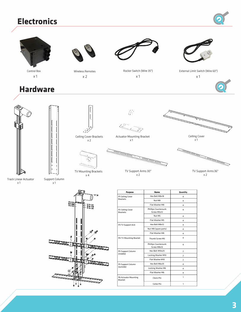
Electronics
Hardware
Control Box Rocker Switch (Wire 35") External Limit Switch (Wire 60")
x 1 x 1 x 1Wireless Remotes
x 2
Track Linear Actuatorx 1
Support Column x 1
Ceiling Cover Brackets x 2
Actuator Mounting Bracketx 1
TV Mounting Brackets x 4
Ceiling Cover x 1
TV Support Arms 30" x 2
TV Support Arms 36" x 2
Purpose Name Quantity
P1 Ceiling Cover Brackets
Hex Bolt M8x18 4
Nut M8 4
Flat Washer M8 4
P2 Ceiling Cover Brackets
Phillips Countersunk
Screw M5x12 4
Nut M5 4
Flat Washer M5 4
P3 TV Support Arm Hex Bolt M8x12 4
Nut M8 (spare parts) 4
Flat Washer M8 4
P4 TV Mounting Bracket Thumb Screw M5 4
Phillips Countersunk
Screw M8x12 4
P5 Support Column (middle)
Hex Bolt M10x25 2
Locking Washer M10 2
Flat Washer M10 2
Hex Bolt M6x25 4
Locking Washer M6 4
Flat Washer M6 4
P6 Actuator Mounting Bracket
Clevis Pin 1
Cotter Pin 1
P5 Support Column (outside)
4
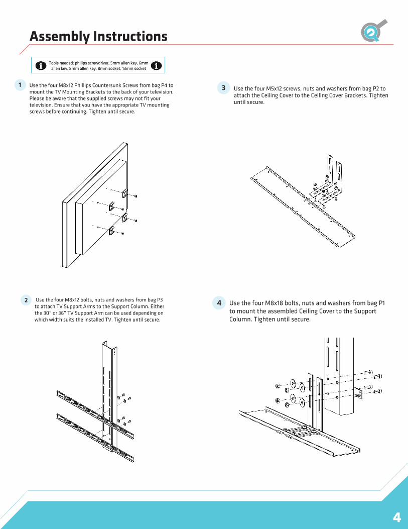
Assembly Instructions
Use the four M8x12 Phillips Countersunk Screws from bag P4 to mount the TV Mounting Brackets to the back of your television. Please be aware that the supplied screws may not fit your television. Ensure that you have the appropriate TV mounting screws before continuing. Tighten until secure.
1
Tools needed: philips screwdriver, 5mm allen key, 6mm allen key, 8mm allen key, 8mm socket, 13mm socket
Use the four M8x12 bolts, nuts and washers from bag P3 to attach TV Support Arms to the Support Column. Either the 30” or 36” TV Support Arm can be used depending on which width suits the installed TV. Tighten until secure.
2
3 use the four M5x12 screws, nuts and washers from bag P2 to attach the Ceiling Cover to the Ceiling Cover Brackets. Tighten until secure.
Use the four M8x18 bolts, nuts and washers from bag P1 to mount the assembled Ceiling Cover to the Support Column. Tighten until secure.
4

Assembly Instructions
5
5 Use the Actuator Mount Bracket, Clevis Pin and Cotter Pinfrom bag P6 to mount the top portion of the Track Linear Actuator to your installation. The bottom portion comes with an attached bracket for installation. The wood screws shown in the diagram are not included. Tighten until secure.
6 For this step we recommend having at least twopeople. From bag P6, use the four M6x25 bolts and washers for the smaller holes on the outside and the two M10x25 bolts and washers for the middle holes to mount the assembled Support Column to the Track Linear Actuator. Install all of the bolts before tightening to ensure proper alignment.
Now that your Drop Down TV Lift is assembled you can attach your TV Mounting Brackets to the TV Support Arms using the four M8x12 screws. Tighten until secure.
7
Your Drop Down TV Lift is now fully assembled and ready for use.
8

Assembly Instructions
6
To program the wireless remote for the control box, press and hold the reset button on the side of the control box. While the reset button is held, press either the up or down button on the wireless remote once. The reset button can now be released and the wireless remote is ready for use.
Please keep in mind this procedure is completely optional and does not need to be set up in order for the TV Lift to operate. The external limit switch stops the lift from moving once it is pressed. Please note that the external limit switch will only operate in the extending direction.
Install the switch in a way that it will be pressed while the lift is moving up and right before the ceiling cover touches the ceiling.
9 Programming Wireless Remotes 11 External Limit Switch
Reset Button
Lift Operation
Before operation please ensure that there are no obstructions in the path of the TV Lift. Once the wireless remotes are programmed to the control box, the wireless remote can be used for non-momentary operation. Press the up button once to move the lift up and press the up or down button to stop. To move the lift down, press the down button once and press the down or up button to stop.
If you'd like momentary control then use the optional Rocker Switch. To use it, simply plug it into the control box and hold ‘2’ on the Rocker Switch to move the lift up and hold ‘1’ to move the lift down.
10
Rocker Switch
Limit SwitchActuator