Embed Size (px)
Citation preview
igus® (UK) Ltd | Phone (01604) 677240 Fax -245 | [email protected] | www.igus.co.uk 1089
drylin®
drivetechnology
Lifetime calculation, CAD files and much more support www.igus.co.uk/en/drylinZLW
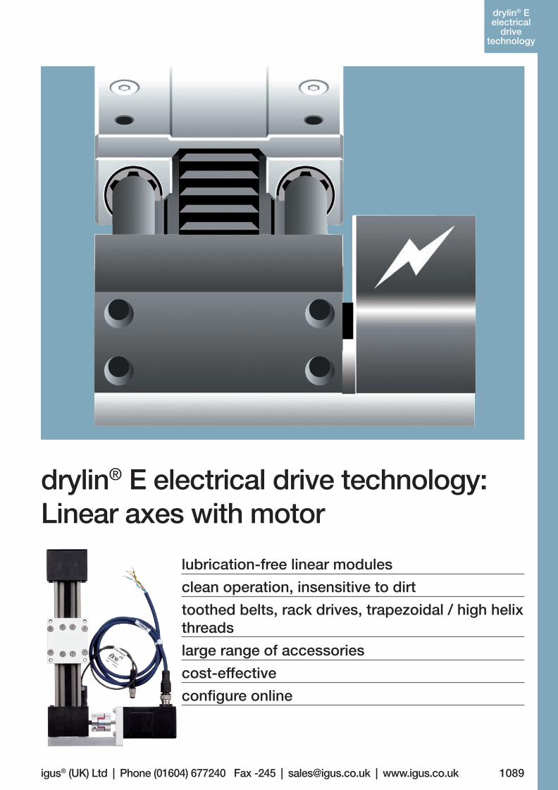
lubrication-free linear modules
clean operation, insensitive to dirt
toothed belts, rack drives, trapezoidal / high helix threads
large range of accessories
cost-effective
configure online
drylin® E electrical drive technology: Linear axes with motor
drylin® E electrical
drive technology
06_GL6_UK_drylin_Antrieb.indd 83 26.02.13 10:49
1090
drylin® SHT- Linear-
achsen
drylin® E electrical
drive technology drylin® E | Linear Axes with Motor
More information www.igus.co.uk/en/drylinE
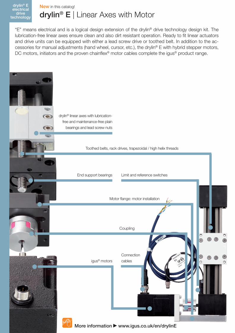
“E” means electrical and is a logical design extension of the drylin® drive technology design kit. The lubrication-free linear axes ensure clean and also dirt resistant operation. Ready to fit linear actuators and drive units can be equipped with either a lead screw drive or toothed belt. In addition to the ac-cessories for manual adjustments (hand wheel, cursor, etc.), the drylin® E with hybrid stepper motors, DC motors, initiators and the proven chainflex® motor cables complete the igus® product range.
drylin® linear axes with lubrication-
free and maintenance-free plain
bearings and lead screw nuts
Toothed belts, rack drives, trapezoidal / high helix threads
End support bearings
Motor flange: motor installation
Coupling
igus® motors
Connection
cables
Limit and reference switches
New in this catalog!
06_GL6_UK_drylin_Antrieb.indd 84 26.02.13 10:49
1091
drylin® SHT- Linear-
achsen
igus® (UK) Ltd | Phone (01604) 677240 Fax -245 | [email protected] | www.igus.co.uk
drylin® E electrical
drive technologydrylin® E | Application examples
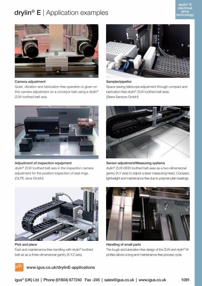
Camera adjustment
Quiet, vibration and lubrication-free operation is given on
this camera adjustment on a conveyor belt using a drylin®
ZLW toothed belt axis.
Sampler/pipettor
Space-saving telescope adjustment through compact and
lubrication-free drylin® ZLW toothed belt axes.
(Sierra Sensors GmbH)
Adjustment of inspection equipment
drylin® ZLW toothed belt axis in the inspection camera
adjustment for the position inspection of seal rings.
(OLPE Jena GmbH)
Sensor adjustment/Measuring systems
drylin® ZLW-0630 toothed belt axes as a two-dimensional
gantry (X,Y axis) to adjust a laser measuring head. Compact,
lightweight and maintenance-free due to polymer plain bearings.
Pick and place
Fast and maintenance-free handling with drylin® toothed
belt as as a three-dimensional gantry (X,Y,Z axis).
Handling of small parts
The tough and lubrication-free design of the ZLW and drylin® W
profiles allows a long and maintenance-free process cycle.
www.igus.co.uk/drylinE-applications
06_GL6_UK_drylin_Antrieb.indd 85 26.02.13 10:50
1092
drylin® SHT- Linear-
achsen
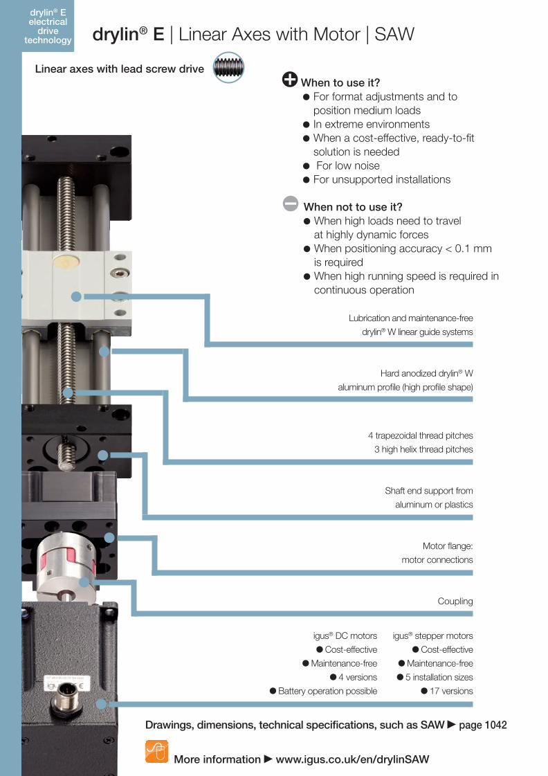
When to use it? For format adjustments and to position medium loads In extreme environments When a cost-effective, ready-to-fit solution is needed For low noise For unsupported installations
drylin® E elektrische Antriebs-technik drylin® E | Linear Axes with Motor | SAW
More information www.igus.co.uk/en/drylinSAW
Linear axes with lead screw drive
Lubrication and maintenance-free
drylin® W linear guide systems
4 trapezoidal thread pitches
3 high helix thread pitches
Shaft end support from
aluminum or plastics
Motor flange:
motor connections
Coupling
Hard anodized drylin® W
aluminum profile (high profile shape)
igus® DC motors
Cost-effective
Maintenance-free
4 versions
Battery operation possible
When not to use it? When high loads need to travel at highly dynamic forces When positioning accuracy < 0.1 mm is required When high running speed is required in
continuous operation
igus® stepper motors
Cost-effective
Maintenance-free
5 installation sizes
17 versions
drylin® E electrical
drive technology
Drawings, dimensions, technical specifications, such as SAW page 1042
06_GL6_UK_drylin_Antrieb.indd 86 26.02.13 10:50
1093
drylin® SHT- Linear-
achsen
igus® (UK) Ltd | Phone (01604) 677240 Fax -245 | [email protected] | www.igus.co.uk
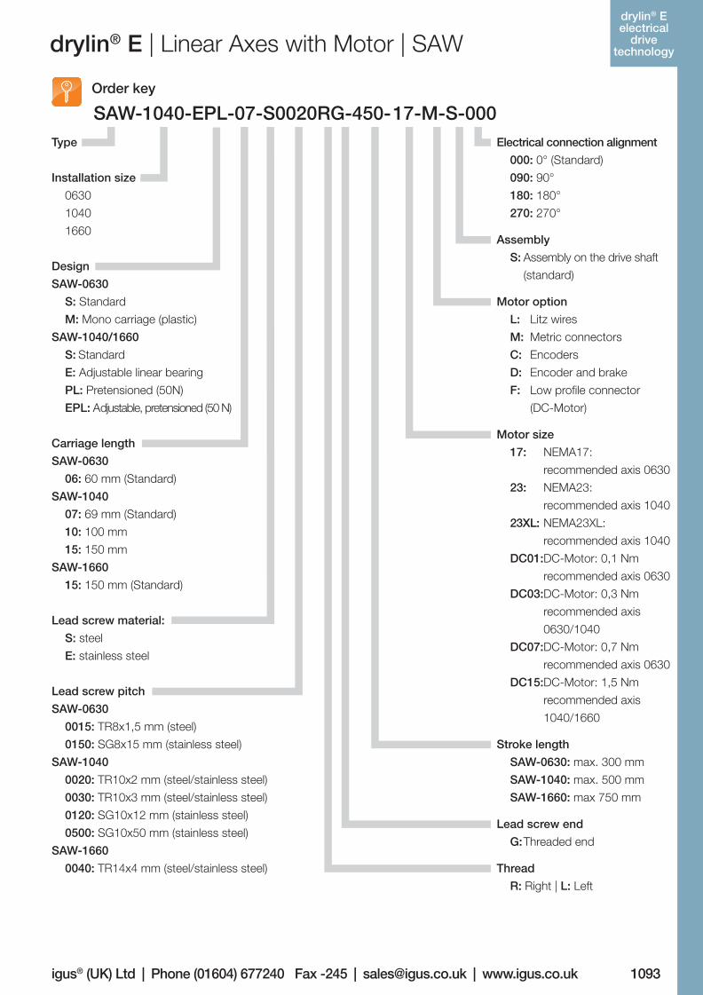
drylin® E | Linear Axes with Motor | SAW
Design
SAW-0630
S: Standard
M: Mono carriage (plastic)
SAW-1040/1660
S: Standard
E: Adjustable linear bearing
PL: Pretensioned (50N)
EPL: Adjustable, pretensioned (50 N)
Thread
R: Right | L: Left
Lead screw pitch
SAW-0630
0015: TR8x1,5 mm (steel)
0150: SG8x15 mm (stainless steel)
SAW-1040
0020: TR10x2 mm (steel/stainless steel)
0030: TR10x3 mm (steel/stainless steel)
0120: SG10x12 mm (stainless steel)
0500: SG10x50 mm (stainless steel)
SAW-1660
0040: TR14x4 mm (steel/stainless steel)
SAW-1040-EPL-07-S0020RG-450-17-M-S-000Order key
Electrical connection alignment
000: 0° (Standard)
090: 90°
180: 180°
270: 270°
Assembly
S: Assembly on the drive shaft
(standard)
Motor option
L: Litz wires
M: Metric connectors
C: Encoders
D: Encoder and brake
F: Low profile connector
(DC-Motor)
Motor size
17: NEMA17:
recommended axis 0630
23: NEMA23:
recommended axis 1040
23XL: NEMA23XL:
recommended axis 1040
DC01:DC-Motor: 0,1 Nm
recommended axis 0630
DC03:DC-Motor: 0,3 Nm
recommended axis
0630/1040
DC07:DC-Motor: 0,7 Nm
recommended axis 0630
DC15:DC-Motor: 1,5 Nm
recommended axis
1040/1660
Stroke length
SAW-0630: max. 300 mm
SAW-1040: max. 500 mm
SAW-1660: max 750 mm
Lead screw end
G: Threaded end
Lead screw material:
S: steel
E: stainless steel
Carriage length
SAW-0630
06: 60 mm (Standard)
SAW-1040
07: 69 mm (Standard)
10: 100 mm
15: 150 mm
SAW-1660
15: 150 mm (Standard)
Type
Installation size
0630
1040
1660
drylin® E electrical
drive technology
06_GL6_UK_drylin_Antrieb.indd 87 26.02.13 10:50
1094
drylin® SHT- Linear-
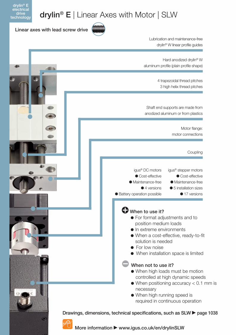
achsen drylin® E | Linear Axes with Motor | SLW
More information www.igus.co.uk/en/drylinSLW
Linear axes with lead screw drive
When to use it? For format adjustments and to position medium loads In extreme environments When a cost-effective, ready-to-fit solution is needed For low noise When installation space is limited
Lubrication and maintenance-free
drylin® W linear profile guides
4 trapezoidal thread pitches
3 high helix thread pitches
Shaft end supports are made from
anodized aluminum or from plastics
Motor flange:
motor connections
Coupling
Hard anodized drylin® W
aluminum profile (plain profile shape)
igus® DC motors
Cost-effective
Maintenance-free
4 versions
Battery operation possible
When not to use it? When high loads must be motion controlled at high dynamic speeds When positioning accuracy < 0.1 mm is necessary When high running speed is required in continuous operation
igus® stepper motors
Cost-effective
Maintenance-free
5 installation sizes
17 versions
Drawings, dimensions, technical specifications, such as SLW page 1038
drylin® E electrical
drive technology
06_GL6_UK_drylin_Antrieb.indd 88 26.02.13 10:50
1095
drylin® SHT- Linear-
achsen
igus® (UK) Ltd | Phone (01604) 677240 Fax -245 | [email protected] | www.igus.co.uk
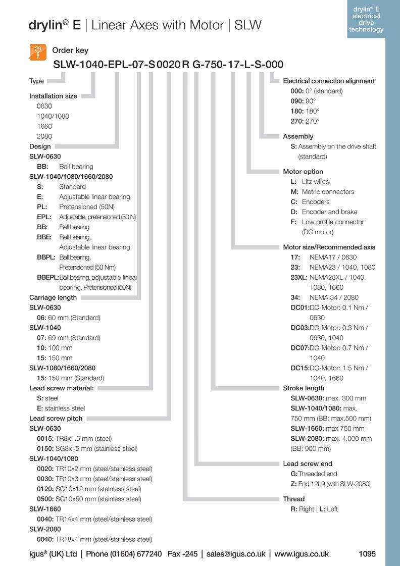
drylin® E | Linear Axes with Motor | SLW
Design
SLW-0630
BB:
SLW-1040/1080/1660/2080
S:
E:
PL:
EPL:
BB:
BBE:
BBPL:
BBEPL:
Ball bearing
Standard
Adjustable linear bearing
Pretensioned (50N)
Adjustable, pretensioned (50 N)
Ball bearing
Ball bearing,
Adjustable linear bearing
Ball bearing,
Pretensioned (50 Nm)
Ball bearing, adjustable linear
bearing, Pretensioned (50N)
Thread
R: Right | L: Left
Lead screw pitch
SLW-0630
0015: TR8x1.5 mm (steel)
0150: SG8x15 mm (stainless steel)
SLW-1040/1080
0020: TR10x2 mm (steel/stainless steel)
0030: TR10x3 mm (steel/stainless steel)
0120: SG10x12 mm (stainless steel)
0500: SG10x50 mm (stainless steel)
SLW-1660
0040: TR14x4 mm (steel/stainless steel)
SLW-2080
0040: TR18x4 mm (steel/stainless steel)
SLW-1040-EPL-07-S 0020 R G-750-17-L-S-000Order key
Electrical connection alignment
000: 0° (standard)
090: 90°
180: 180°
270: 270°
Assembly
S: Assembly on the drive shaft
(standard)
Motor option
L: Litz wires
M: Metric connectors
C: Encoders
D: Encoder and brake
F: Low profile connector
(DC motor)
Motor size/Recommended axis
17: NEMA17 / 0630
23: NEMA23 / 1040, 1080
23XL: NEMA23XL / 1040,
1080, 1660
34: NEMA 34 / 2080
DC01:DC-Motor: 0.1 Nm /
0630
DC03:DC-Motor: 0.3 Nm /
0630, 1040
DC07:DC-Motor: 0.7 Nm /
1040
DC15:DC-Motor: 1.5 Nm /
1040, 1660
Stroke length
SLW-0630: max. 300 mm
SLW-1040/1080: max.
750 mm (BB: max.500 mm)
SLW-1660: max 750 mm
SLW-2080: max. 1,000 mm
(BB: 900 mm)
Lead screw end
G: Threaded end
Z: End 12h9 (with SLW-2080)
Lead screw material:
S: steel
E: stainless steel
Carriage length
SLW-0630
06: 60 mm (Standard)
SLW-1040
07: 69 mm (Standard)
10: 100 mm
15: 150 mm
SLW-1080/1660/2080
15: 150 mm (Standard)
Installation size
0630
1040/1080
1660
2080
Type
drylin® E electrical
drive technology
06_GL6_UK_drylin_Antrieb.indd 89 26.02.13 10:50
drylin® SHT- Linear-
achsen
1096
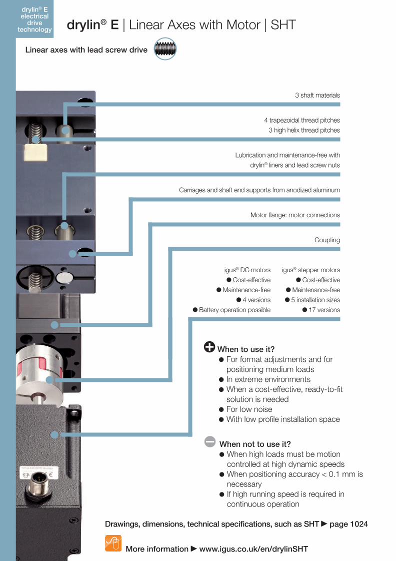
drylin® E | Linear Axes with Motor | SHT
More information www.igus.co.uk/en/drylinSHT
Linear axes with lead screw drive
drylin® E electrical
drive technology
When to use it? For format adjustments and for positioning medium loads In extreme environments When a cost-effective, ready-to-fit solution is needed For low noise With low profile installation space
4 trapezoidal thread pitches
3 high helix thread pitches
Carriages and shaft end supports from anodized aluminum
Lubrication and maintenance-free with
drylin® liners and lead screw nuts
Motor flange: motor connections
Coupling
3 shaft materials
igus® DC motors
Cost-effective
Maintenance-free
4 versions
Battery operation possible
When not to use it? When high loads must be motion
controlled at high dynamic speeds When positioning accuracy < 0.1 mm is
necessary If high running speed is required in
continuous operation
igus® stepper motors
Cost-effective
Maintenance-free
5 installation sizes
17 versions
Drawings, dimensions, technical specifications, such as SHT page 1024
06_GL6_UK_drylin_Antrieb.indd 90 26.02.13 10:50
1097
drylin® SHT- Linear-
achsen
igus® (UK) Ltd | Phone (01604) 677240 Fax -245 | [email protected] | www.igus.co.uk
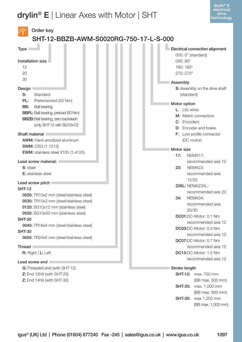
drylin® E | Linear Axes with Motor | SHT
Design
S:
PL:
BB:
BBPL:
BBZB:
Thread
R: Right | L: Left
Lead screw pitch
SHT-12
0020: TR10x2 mm (steel/stainless steel)
0030: TR10x3 mm (steel/stainless steel)
0120: SG10x12 mm (stainless steel)
0500: SG10x50 mm (stainless steel)
SHT-20
0040: TR18x4 mm (steel/stainless steel)
SHT-30
0050: TR24x5 mm (steel/stainless steel)
SHT-12-BBZB-AWM-S0020RG-750-17-L-S-000Order key
Electrical connection alignment
000: 0° (standard)
090: 90°
180: 180°
270: 270°
Assembly
S: Assembly on the drive shaft
(standard)
Motor option
L: Litz wires
M: Metric connectors
C: Encoders
D: Encoder and brake
F: Low profile connector
(DC motor)
Motor size
17: NEMA17:
recommended axis 12
23: NEMA23:
recommended axis
12/20
23XL: NEMA23XL:
recommended axis 20
34: NEMA34:
recommended axis
20/30
DC01:DC-Motor: 0.1 Nm
recommended axis 12
DC03:DC-Motor: 0.3 Nm
recommended axis 12
DC07:DC-Motor: 0.7 Nm
recommended axis 12
DC15:DC-Motor: 1.5 Nm
recommended axis 12
Stroke length
SHT-12: max. 750 mm
(BB max. 500 mm)
SHT-20: max. 1,000 mm
(BB max. 900 mm)
SHT-30: max 1,250 mm
(BB max. 1,000 mm)
Lead screw end
G: Threaded end (with SHT-12)
Z: End 12h9 (with SHT-20)
Z: End 14h9 (with SHT-30)
Lead screw material:
S: steel
E: stainless steel
Shaft material
AWM: Hard-anodized aluminum
SWM: Cf53 (1.1213)
EWM: stainless steel X105 (1.4125)
Type
Installation size
12
20
30
Standard
Pretensioned (50 Nm)
Ball bearing
Ball bearing, preload (50 Nm)
Ball bearing, zero backslash
(only SHT-12 with SG10x12)
drylin® E electrical
drive technology
06_GL6_UK_drylin_Antrieb.indd 91 26.02.13 10:50
1098
drylin® SHT- Linear-
achsen
More information www.igus.co.uk/en/drylinSHT
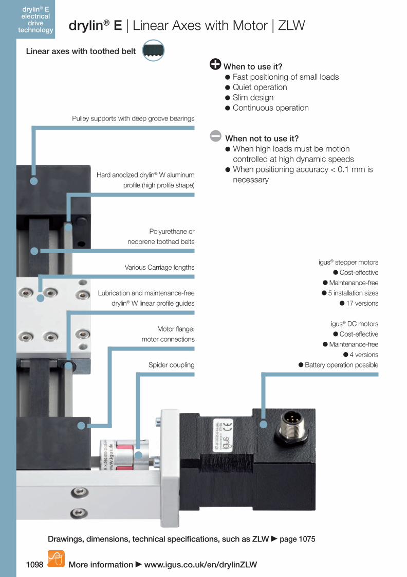
Pulley supports with deep groove bearings
Lubrication and maintenance-free
drylin® W linear profile guides
Hard anodized drylin® W aluminum
profile (high profile shape)
Various Carriage lengths
Polyurethane or
neoprene toothed belts
drylin® E | Linear Axes with Motor | ZLW
Linear axes with toothed belt
When to use it? Fast positioning of small loads Quiet operation Slim design Continuous operation
When not to use it? When high loads must be motion
controlled at high dynamic speeds When positioning accuracy < 0.1 mm is
necessary
igus® DC motors
Cost-effective
Maintenance-free
4 versions
Battery operation possible
Motor flange:
motor connections
Spider coupling
igus® stepper motors
Cost-effective
Maintenance-free
5 installation sizes
17 versions
More information www.igus.co.uk/en/drylinZLW
Drawings, dimensions, technical specifications, such as ZLW page 1075
drylin® E electrical
drive technology
06_GL6_UK_drylin_Antrieb.indd 92 26.02.13 10:50
1099
drylin® SHT- Linear-
achsen
igus® (UK) Ltd | Phone (01604) 677240 Fax -245 | [email protected] | www.igus.co.uk
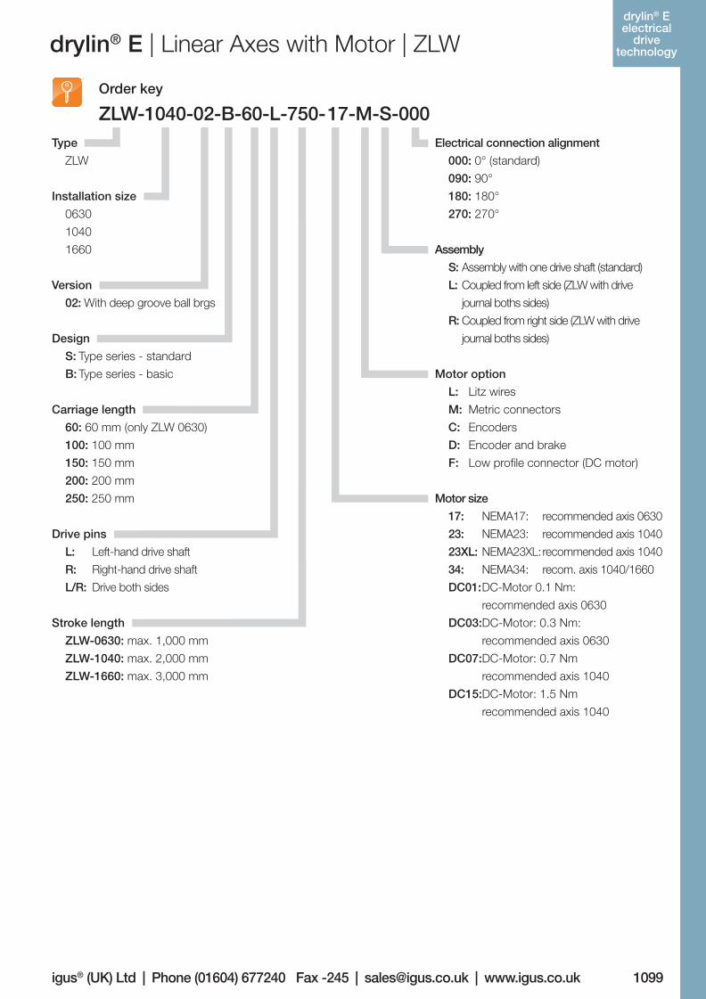
drylin® E | Linear Axes with Motor | ZLW
Order key
ZLW-1040-02-B-60-L-750-17-M-S-000
Motor size
17: NEMA17: recommended axis 0630
23: NEMA23: recommended axis 1040
23XL: NEMA23XL: recommended axis 1040
34: NEMA34: recom. axis 1040/1660
DC01: DC-Motor 0.1 Nm:
recommended axis 0630
DC03:DC-Motor: 0.3 Nm:
recommended axis 0630
DC07:DC-Motor: 0.7 Nm
recommended axis 1040
DC15:DC-Motor: 1.5 Nm
recommended axis 1040
Electrical connection alignment
000: 0° (standard)
090: 90°
180: 180°
270: 270°
Assembly
S: Assembly with one drive shaft (standard)
L: Coupled from left side (ZLW with drive
journal boths sides)
R: Coupled from right side (ZLW with drive
journal boths sides)
Motor option
L: Litz wires
M: Metric connectors
C: Encoders
D: Encoder and brake
F: Low profile connector (DC motor)
Version
02: With deep groove ball brgs
Installation size
0630
1040
1660
Type
ZLW
Stroke length
ZLW-0630: max. 1,000 mm
ZLW-1040: max. 2,000 mm
ZLW-1660: max. 3,000 mm
Drive pins
L: Left-hand drive shaft
R: Right-hand drive shaft
L/R: Drive both sides
Carriage length
60: 60 mm (only ZLW 0630)
100: 100 mm
150: 150 mm
200: 200 mm
250: 250 mm
Design
S: Type series - standard
B: Type series - basic
drylin® E electrical
drive technology
06_GL6_UK_drylin_Antrieb.indd 93 26.02.13 10:50
1100
drylin® SHT- Linear-
achsen
More information www.igus.co.uk/en/drylin
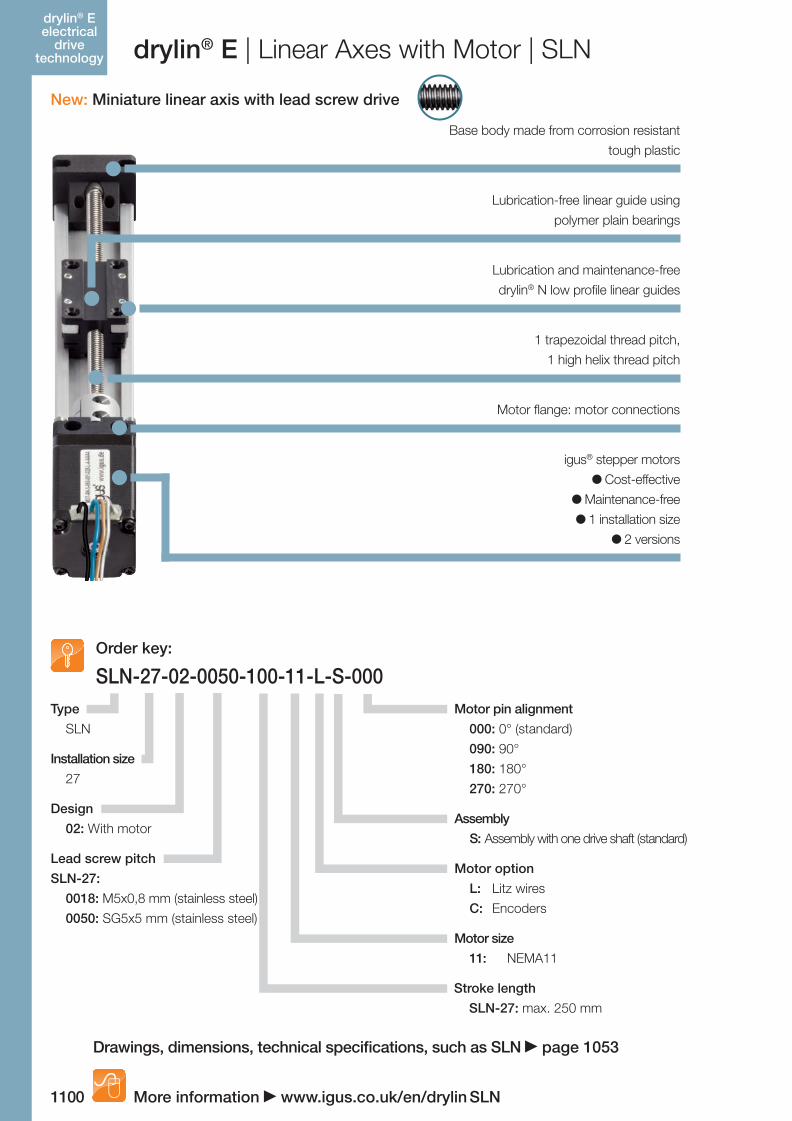
drylin® E | Linear Axes with Motor | SLN
New: Miniature linear axis with lead screw drive
Base body made from corrosion resistant
tough plastic
Lubrication-free linear guide using
polymer plain bearings
Lubrication and maintenance-free
drylin® N low profile linear guides
Motor flange: motor connections
1 trapezoidal thread pitch,
1 high helix thread pitch
igus® stepper motors
Cost-effective
Maintenance-free
1 installation size
2 versions
SLN-27-02-0050-100-11-L-S-000Order key:
Motor pin alignment
000: 0° (standard)
090: 90°
180: 180°
270: 270°
Assembly
S: Assembly with one drive shaft (standard)
Installation size
27
Design
02: With motor
Type
SLN
Motor option
L: Litz wires
C: Encoders
Motor size
11: NEMA11
Stroke length
SLN-27: max. 250 mm
Lead screw pitch
SLN-27:
0018: M5x0,8 mm (stainless steel)
0050: SG5x5 mm (stainless steel)
SLN
Drawings, dimensions, technical specifications, such as SLN page 1053
drylin® E electrical
drive technology
06_GL6_UK_drylin_Antrieb.indd 94 26.02.13 10:50
1101
drylin® SHT- Linear-
achsen
igus® (UK) Ltd | Phone (01604) 677240 Fax -245 | [email protected] | www.igus.co.uk
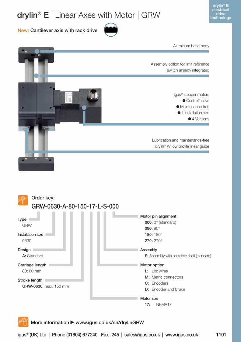
drylin® E | Linear Axes with Motor | GRW
New: Cantilever axis with rack drive
Aluminum base body
Assembly option for limit reference
switch already integrated
Lubrication and maintenance-free
drylin® W low profile linear guide
igus® stepper motors
Cost-effective
Maintenance-free
1 installation size
4 Versions
GRW-0630-A-80-150-17-L-S-000Order key:
Motor pin alignment
000: 0° (standard)
090: 90°
180: 180°
270: 270°
Assembly
S: Assembly with one drive shaft (standard)
Installation size
0630
Design
A: Standard
Type
GRW
Motor size
17: NEMA17
Stroke length
GRW-0630: max. 150 mm
Carriage length
80: 80 mm
Motor option
L: Litz wires
M: Metric connectors
C: Encoders
D: Encoder and brake
More information www.igus.co.uk/en/drylinGRW
drylin® E electrical
drive technology
06_GL6_UK_drylin_Antrieb.indd 95 26.02.13 10:50
1102
drylin® SHT- Linear-
achsen
Lifetime calculation, CAD files and much more support www.igus.co.uk/en/drylinE
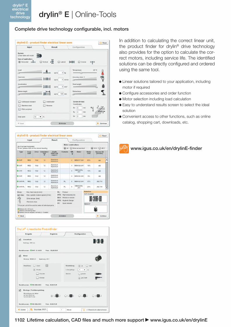
drylin® E | Online-Tools
Complete drive technology configurable, incl. motors
www.igus.co.uk/en/drylinE-finder
In addition to calculating the correct linear unit, the product finder for drylin® drive technology also provides for the option to calculate the cor-rect motors, including service life. The identified solutions can be directly configured and ordered using the same tool.
Linear solutions tailored to your application, including
motor if required
Configure accessories and order function
Motor selection including load calculation
Easy to understand results screen to select the ideal
solution
Convenient access to other functions, such as online
catalog, shopping cart, downloads, etc.
drylin® E electrical
drive technology
06_GL6_UK_drylin_Antrieb.indd 96 26.02.13 10:50
Lifetime calculation, CAD files and much more support www.igus.co.uk/en/drylinE 1103
drylin® SHT- Linear-
achsen
igus® (UK) Ltd | Phone (01604) 677240 Fax -245 | [email protected] | www.igus.co.uk
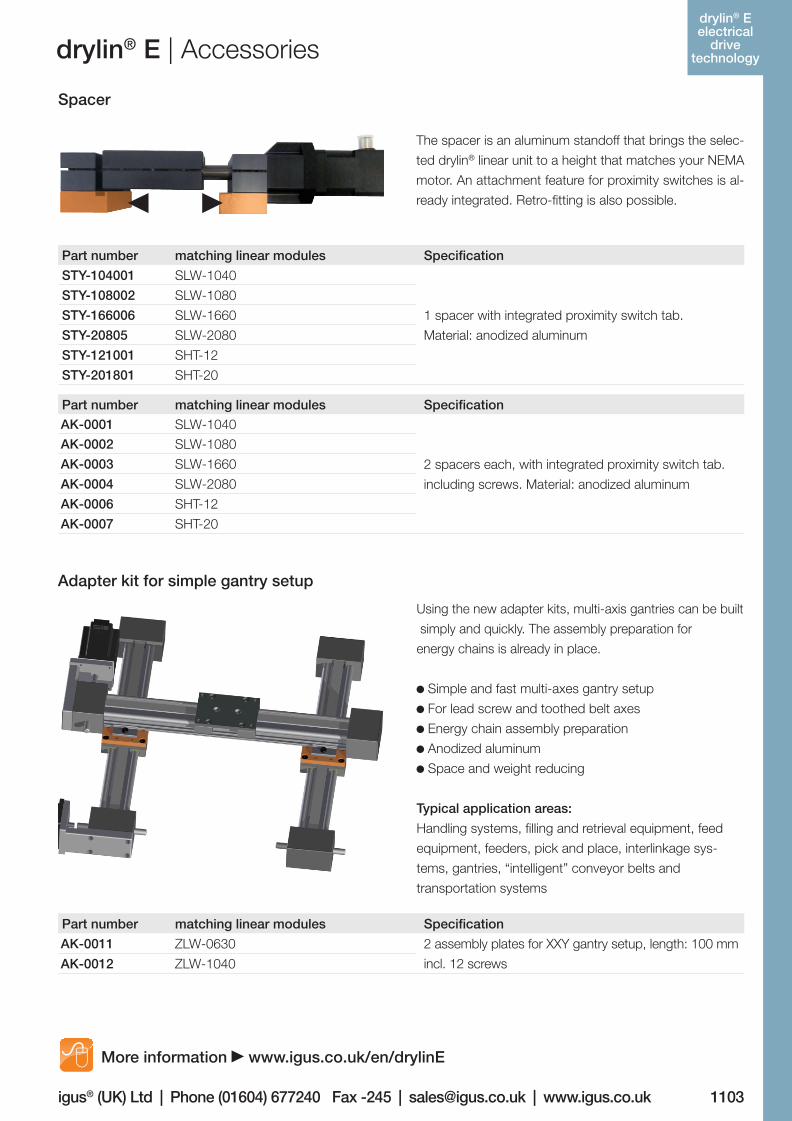
drylin® E | Accessories
Spacer
Adapter kit for simple gantry setup
Part number matching linear modules Specification
STY-104001 SLW-1040
1 spacer with integrated proximity switch tab.
Material: anodized aluminum
STY-108002 SLW-1080
STY-166006 SLW-1660
STY-20805 SLW-2080
STY-121001 SHT-12
STY-201801 SHT-20
The spacer is an aluminum standoff that brings the selec-
ted drylin® linear unit to a height that matches your NEMA
motor. An attachment feature for proximity switches is al-
ready integrated. Retro-fitting is also possible.
Part number matching linear modules Specification
AK-0011 ZLW-0630 2 assembly plates for XXY gantry setup, length: 100 mm
incl. 12 screwsAK-0012 ZLW-1040
Part number matching linear modules Specification
AK-0001 SLW-1040
2 spacers each, with integrated proximity switch tab.
including screws. Material: anodized aluminum
AK-0002 SLW-1080
AK-0003 SLW-1660
AK-0004 SLW-2080
AK-0006 SHT-12
AK-0007 SHT-20
More information www.igus.co.uk/en/drylinE
Using the new adapter kits, multi-axis gantries can be built
simply and quickly. The assembly preparation for
energy chains is already in place.
Simple and fast multi-axes gantry setup
For lead screw and toothed belt axes
Energy chain assembly preparation
Anodized aluminum
Space and weight reducing
Typical application areas:
Handling systems, filling and retrieval equipment, feed
equipment, feeders, pick and place, interlinkage sys-
tems, gantries, “intelligent” conveyor belts and
transportation systems
drylin® E electrical
drive technology
06_GL6_UK_drylin_Antrieb.indd 97 26.02.13 10:50
1104
drylin® SHT- Linear-
achsen
Lifetime calculation, CAD files and much more support www.igus.co.uk/en/drylinE
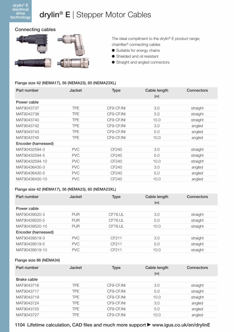
drylin® E | Stepper Motor Cables
Connecting cables
Part number Jacket Type Cable length Connectors[m]
Power cable
MAT9043737 TPE CF9-CF.INI 3.0 straight
MAT9043738 TPE CF9-CF.INI 5.0 straight
MAT9043740 TPE CF9-CF.INI 10.0 straight
MAT9043742 TPE CF9-CF.INI 3.0 angled
MAT9043743 TPE CF9-CF.INI 5.0 angled
MAT9043745 TPE CF9-CF.INI 10.0 angled
Encoder (harnessed)
MAT90432594-3 PVC CF240 3.0 straight
MAT90432594-5 PVC CF240 5.0 straight
MAT90432594-10 PVC CF240 10.0 straight
MAT90436430-3 PVC CF240 3.0 angled
MAT90436430-5 PVC CF240 5.0 angled
MAT90436430-10 PVC CF240 10.0 angled
Part number Jacket Type Cable length Connectors[m]
Power cable
MAT90439520-3 PUR CF78.UL 3.0 straight
MAT90439520-5 PUR CF78.UL 5.0 straight
MAT90439520-10 PUR CF78.UL 10.0 straight
Encoder (harnessed)
MAT90439519-3 PVC CF211 3.0 straight
MAT90439519-5 PVC CF211 5.0 straight
MAT90439519-10 PVC CF211 10.0 straight
Part number Jacket Type Cable length Connectors[m]
Brake cable
MAT9043716 TPE CF9-CF.INI 3.0 straight
MAT9043717 TPE CF9-CF.INI 5.0 straight
MAT9043719 TPE CF9-CF.INI 10.0 straight
MAT9043724 TPE CF9-CF.INI 3.0 angled
MAT9043725 TPE CF9-CF.INI 5.0 angled
MAT9043727 TPE CF9-CF.INI 10.0 angled
Flange size 42 (NEMA17), 56 (NEMA23), 60 (NEMA23XL)
Flange size 86 (NEMA34)
Flange size 42 (NEMA17), 56 (NEMA23), 60 (NEMA23XL)
The ideal compliment to the drylin® E product range;
chainflex® connecting cables
Suitable for energy chains
Shielded and oil resistant
Straight and angled connectors
drylin® E electrical
drive technology
06_GL6_UK_drylin_Antrieb.indd 98 26.02.13 10:50
Lifetime calculation, CAD files and much more support www.igus.co.uk/en/drylinE 1105
drylin® SHT- Linear-
achsen
igus® (UK) Ltd | Phone (01604) 677240 Fax -245 | [email protected] | www.igus.co.uk
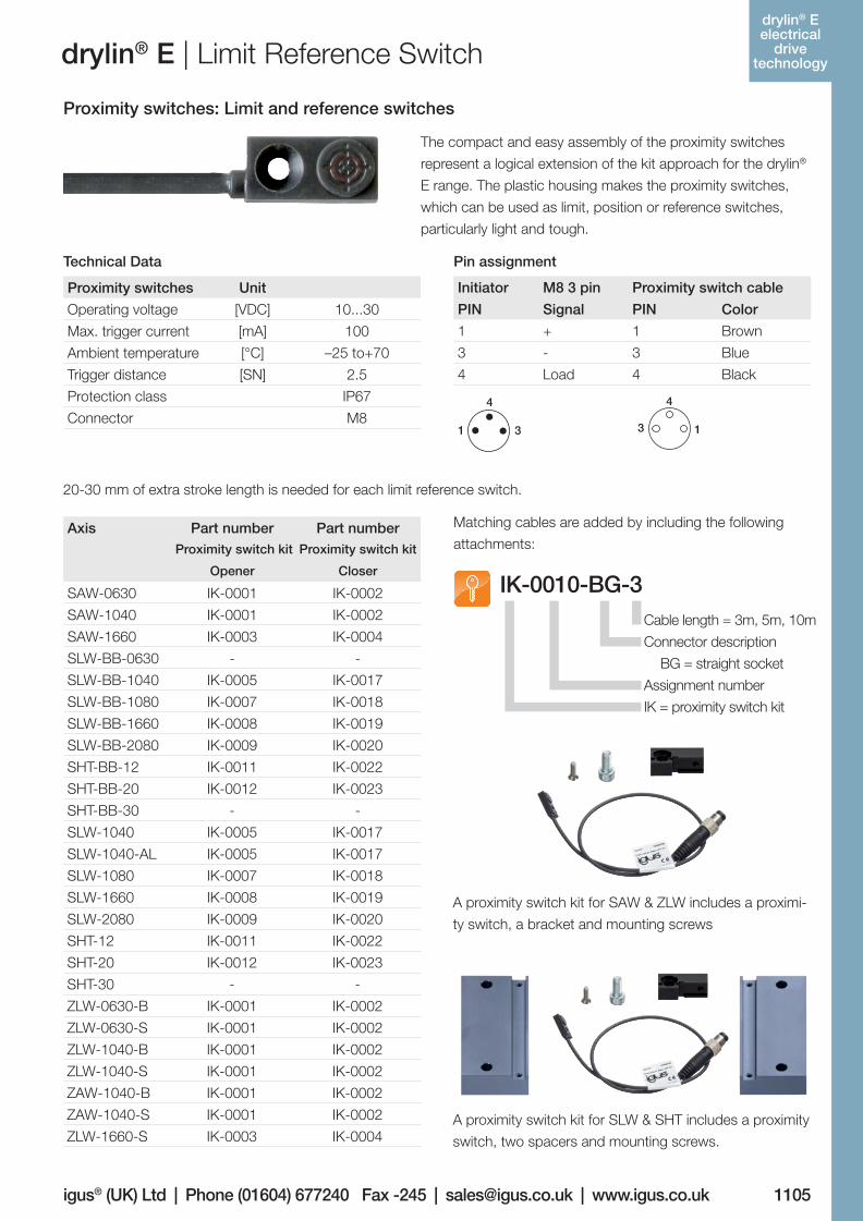
drylin® E | Limit Reference Switch
Proximity switches: Limit and reference switches
Technical Data Pin assignment
The compact and easy assembly of the proximity switches
represent a logical extension of the kit approach for the drylin®
E range. The plastic housing makes the proximity switches,
which can be used as limit, position or reference switches,
particularly light and tough.
20-30 mm of extra stroke length is needed for each limit reference switch.
Matching cables are added by including the following
attachments:
A proximity switch kit for SLW & SHT includes a proximity
switch, two spacers and mounting screws.
A proximity switch kit for SAW & ZLW includes a proximi-
ty switch, a bracket and mounting screws
Cable length = 3m, 5m, 10m
Connector description
BG = straight socket
Assignment number
IK = proximity switch kit
IK-0010-BG-3
Axis Part number Part number Proximity switch kit Proximity switch kit
Opener Closer
SAW-0630 IK-0001 IK-0002
SAW-1040 IK-0001 IK-0002
SAW-1660 IK-0003 IK-0004
SLW-BB-0630 - -
SLW-BB-1040 IK-0005 IK-0017
SLW-BB-1080 IK-0007 IK-0018
SLW-BB-1660 IK-0008 IK-0019
SLW-BB-2080 IK-0009 IK-0020
SHT-BB-12 IK-0011 IK-0022
SHT-BB-20 IK-0012 IK-0023
SHT-BB-30 - -
SLW-1040 IK-0005 IK-0017
SLW-1040-AL IK-0005 IK-0017
SLW-1080 IK-0007 IK-0018
SLW-1660 IK-0008 IK-0019
SLW-2080 IK-0009 IK-0020
SHT-12 IK-0011 IK-0022
SHT-20 IK-0012 IK-0023
SHT-30 - -
ZLW-0630-B IK-0001 IK-0002
ZLW-0630-S IK-0001 IK-0002
ZLW-1040-B IK-0001 IK-0002
ZLW-1040-S IK-0001 IK-0002
ZAW-1040-B IK-0001 IK-0002
ZAW-1040-S IK-0001 IK-0002
ZLW-1660-S IK-0003 IK-0004
Proximity switches Unit
Operating voltage [VDC] 10...30
Max. trigger current [mA] 100
Ambient temperature [°C] –25 to+70
Trigger distance [SN] 2.5
Protection class IP67
Connector M8
Initiator M8 3 pin Proximity switch cable
PIN Signal PIN Color
1 + 1 Brown
3 - 3 Blue
4 Load 4 Black
3
4
1 1
4
3
drylin® E electrical
drive technology
06_GL6_UK_drylin_Antrieb.indd 99 26.02.13 10:50
1106
drylin® SHT- Linear-
achsen
Lifetime calculation, CAD fi les and much more support www.igus.co.uk/en/drylinE
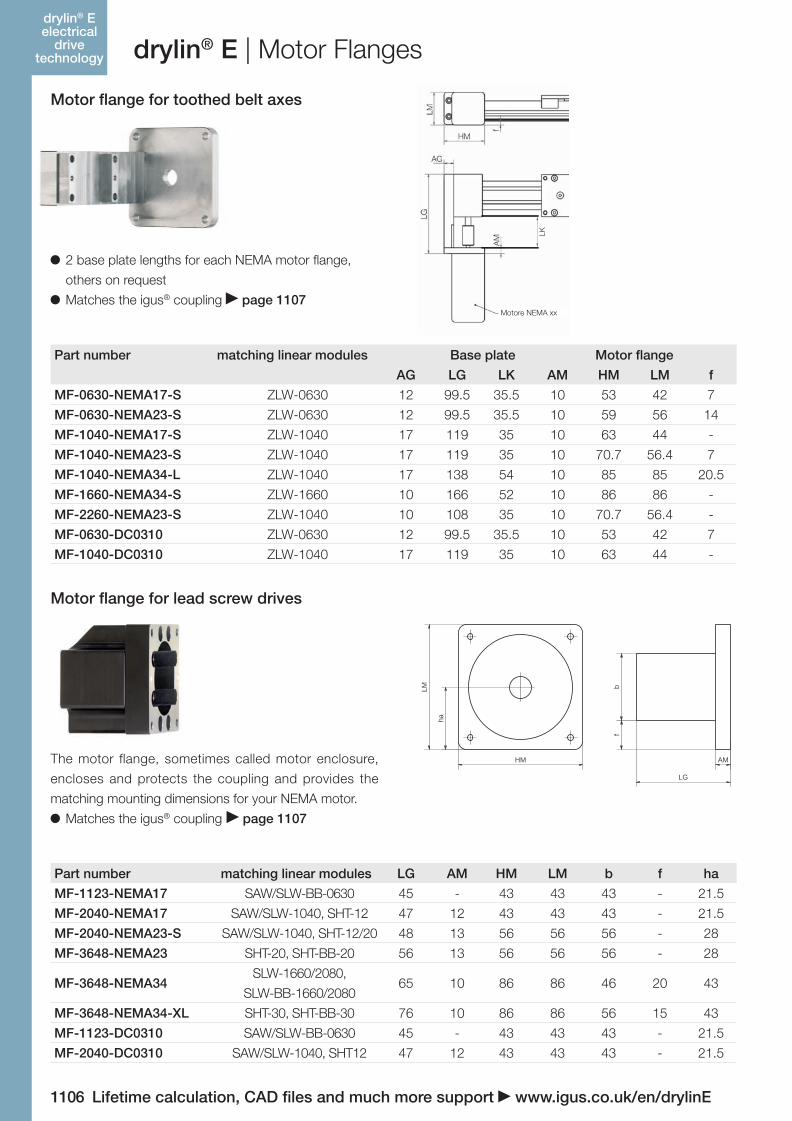
Motor fl ange for toothed belt axes
Motor fl ange for lead screw drives
drylin® E | Motor Flanges
2 base plate lengths for each NEMA motor fl ange,
others on request
Matches the igus® coupling page 1107
The motor flange, sometimes called motor enclosure,
encloses and protects the coupling and provides the
matching mounting dimensions for your NEMA motor.
Matches the igus® coupling page 1107
Part number matching linear modules Base plate Motor fl ange
AG LG LK AM HM LM f
MF-0630-NEMA17-S ZLW-0630 12 99.5 35.5 10 53 42 7
MF-0630-NEMA23-S ZLW-0630 12 99.5 35.5 10 59 56 14
MF-1040-NEMA17-S ZLW-1040 17 119 35 10 63 44 -
MF-1040-NEMA23-S ZLW-1040 17 119 35 10 70.7 56.4 7
MF-1040-NEMA34-L ZLW-1040 17 138 54 10 85 85 20.5
MF-1660-NEMA34-S ZLW-1660 10 166 52 10 86 86 -
MF-2260-NEMA23-S ZLW-1040 10 108 35 10 70.7 56.4 -
MF-0630-DC0310 ZLW-0630 12 99.5 35.5 10 53 42 7
MF-1040-DC0310 ZLW-1040 17 119 35 10 63 44 -
Part number matching linear modules LG AM HM LM b f ha
MF-1123-NEMA17 SAW/SLW-BB-0630 45 - 43 43 43 - 21.5
MF-2040-NEMA17 SAW/SLW-1040, SHT-12 47 12 43 43 43 - 21.5
MF-2040-NEMA23-S SAW/SLW-1040, SHT-12/20 48 13 56 56 56 - 28
MF-3648-NEMA23 SHT-20, SHT-BB-20 56 13 56 56 56 - 28
MF-3648-NEMA34SLW-1660/2080,
SLW-BB-1660/208065 10 86 86 46 20 43
MF-3648-NEMA34-XL SHT-30, SHT-BB-30 76 10 86 86 56 15 43
MF-1123-DC0310 SAW/SLW-BB-0630 45 - 43 43 43 - 21.5
MF-2040-DC0310 SAW/SLW-1040, SHT12 47 12 43 43 43 - 21.5
HM
LM
ha
LG
AM
bf
drylin® E electrical
drive technology
LK
Motore NEMA xx
06_GL6_UK_drylin_Antrieb.indd 100 26.02.13 10:50
Lifetime calculation, CAD files and much more support www.igus.co.uk/en/drylinE 1107
drylin® SHT- Linear-
achsen
igus® (UK) Ltd | Phone (01604) 677240 Fax -245 | [email protected] | www.igus.co.uk
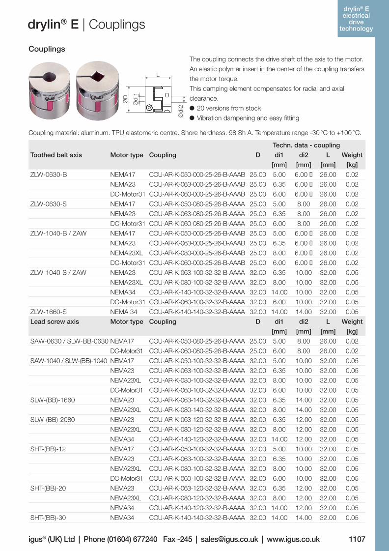
drylin® E | Couplings
CouplingsThe coupling connects the drive shaft of the axis to the motor.
An elastic polymer insert in the center of the coupling transfers
the motor torque.
This damping element compensates for radial and axial
clearance.
20 versions from stock
Vibration dampening and easy fitting
Coupling material: aluminum. TPU elastomeric centre. Shore hardness: 98 Sh A. Temperature range -30 °C to +100 °C.
L
ØD
Ød
i1
Ød
i2
Techn. data - coupling
Toothed belt axis Motor type Coupling D di1 di2 L Weight
[mm] [mm] [mm] [kg]
ZLW-0630-B NEMA17 COU-AR-K-050-000-25-26-B-AAAB 25.00 5.00 6.00 € 26.00 0.02
NEMA23 COU-AR-K-063-000-25-26-B-AAAB 25.00 6.35 6.00 € 26.00 0.02
DC-Motor31 COU-AR-K-060-000-25-26-B-AAAB 25.00 6.00 6.00 € 26.00 0.02
ZLW-0630-S NEMA17 COU-AR-K-050-080-25-26-B-AAAA 25.00 5.00 8.00 26.00 0.02
NEMA23 COU-AR-K-063-080-25-26-B-AAAA 25.00 6.35 8.00 26.00 0.02
DC-Motor31 COU-AR-K-060-080-25-26-B-AAAA 25.00 6.00 8.00 26.00 0.02
ZLW-1040-B / ZAW NEMA17 COU-AR-K-050-000-25-26-B-AAAB 25.00 5.00 6.00 € 26.00 0.02
NEMA23 COU-AR-K-063-000-25-26-B-AAAB 25.00 6.35 6.00 € 26.00 0.02
NEMA23XL COU-AR-K-080-000-25-26-B-AAAB 25.00 8.00 6.00 € 26.00 0.02
DC-Motor31 COU-AR-K-060-000-25-26-B-AAAB 25.00 6.00 6.00 € 26.00 0.02
ZLW-1040-S / ZAW NEMA23 COU-AR-K-063-100-32-32-B-AAAA 32.00 6.35 10.00 32.00 0.05
NEMA23XL COU-AR-K-080-100-32-32-B-AAAA 32.00 8.00 10.00 32.00 0.05
NEMA34 COU-AR-K-140-100-32-32-B-AAAA 32.00 14.00 10.00 32.00 0.05
DC-Motor31 COU-AR-K-060-100-32-32-B-AAAA 32.00 6.00 10.00 32.00 0.05
ZLW-1660-S NEMA 34 COU-AR-K-140-140-32-32-B-AAAA 32.00 14.00 14.00 32.00 0.05
Lead screw axis Motor type Coupling D di1 di2 L Weight
[mm] [mm] [mm] [kg]
SAW-0630 / SLW-BB-0630 NEMA17 COU-AR-K-050-080-25-26-B-AAAA 25.00 5.00 8.00 26.00 0.02
DC-Motor31 COU-AR-K-060-080-25-26-B-AAAA 25.00 6.00 8.00 26.00 0.02
SAW-1040 / SLW-(BB)-1040 NEMA17 COU-AR-K-050-100-32-32-B-AAAA 32.00 5.00 10.00 32.00 0.05
NEMA23 COU-AR-K-063-100-32-32-B-AAAA 32.00 6.35 10.00 32.00 0.05
NEMA23XL COU-AR-K-080-100-32-32-B-AAAA 32.00 8.00 10.00 32.00 0.05
DC-Motor31 COU-AR-K-060-100-32-32-B-AAAA 32.00 6.00 10.00 32.00 0.05
SLW-(BB)-1660 NEMA23 COU-AR-K-063-140-32-32-B-AAAA 32.00 6.35 14.00 32.00 0.05
NEMA23XL COU-AR-K-080-140-32-32-B-AAAA 32.00 8.00 14.00 32.00 0.05
SLW-(BB)-2080 NEMA23 COU-AR-K-063-120-32-32-B-AAAA 32.00 6.35 12.00 32.00 0.05
NEMA23XL COU-AR-K-080-120-32-32-B-AAAA 32.00 8.00 12.00 32.00 0.05
NEMA34 COU-AR-K-140-120-32-32-B-AAAA 32.00 14.00 12.00 32.00 0.05
SHT-(BB)-12 NEMA17 COU-AR-K-050-100-32-32-B-AAAA 32.00 5.00 10.00 32.00 0.05
NEMA23 COU-AR-K-063-100-32-32-B-AAAA 32.00 6.35 10.00 32.00 0.05
NEMA23XL COU-AR-K-080-100-32-32-B-AAAA 32.00 8.00 10.00 32.00 0.05
DC-Motor31 COU-AR-K-060-100-32-32-B-AAAA 32.00 6.00 10.00 32.00 0.05
SHT-(BB)-20 NEMA23 COU-AR-K-063-120-32-32-B-AAAA 32.00 6.35 12.00 32.00 0.05
NEMA23XL COU-AR-K-080-120-32-32-B-AAAA 32.00 8.00 12.00 32.00 0.05
NEMA34 COU-AR-K-140-120-32-32-B-AAAA 32.00 14.00 12.00 32.00 0.05
SHT-(BB)-30 NEMA34 COU-AR-K-140-140-32-32-B-AAAA 32.00 14.00 14.00 32.00 0.05
drylin® E electrical
drive technology
06_GL6_UK_drylin_Antrieb.indd 101 26.02.13 10:50
1108
drylin® SHT- Linear-
achsen
Lifetime calculation, CAD fi les and much more support www.igus.co.uk/en/drylinE
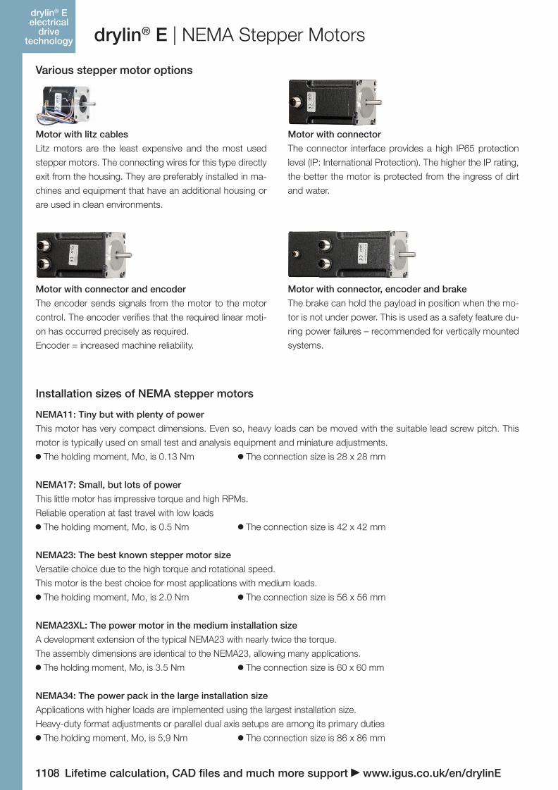
drylin® E | NEMA Stepper Motors
Various stepper motor options
Installation sizes of NEMA stepper motors
NEMA17: Small, but lots of power
This little motor has impressive torque and high RPMs.
Reliable operation at fast travel with low loads
The holding moment, Mo, is 0.5 Nm The connection size is 42 x 42 mm
NEMA11: Tiny but with plenty of power
This motor has very compact dimensions. Even so, heavy loads can be moved with the suitable lead screw pitch. This
motor is typically used on small test and analysis equipment and miniature adjustments.
The holding moment, Mo, is 0.13 Nm The connection size is 28 x 28 mm
Motor with litz cables
Litz motors are the least expensive and the most used
stepper motors. The connecting wires for this type directly
exit from the housing. They are preferably installed in ma-
chines and equipment that have an additional housing or
are used in clean environments.
Motor with connector and encoder
The encoder sends signals from the motor to the motor
control. The encoder verifi es that the required linear moti-
on has occurred precisely as required.
Encoder = increased machine reliability.
Motor with connector, encoder and brake
The brake can hold the payload in position when the mo-
tor is not under power. This is used as a safety feature du-
ring power failures – recommended for vertically mounted
systems.
Motor with connector
The connector interface provides a high IP65 protection
level (IP: International Protection). The higher the IP rating,
the better the motor is protected from the ingress of dirt
and water.
NEMA23: The best known stepper motor size
Versatile choice due to the high torque and rotational speed.
This motor is the best choice for most applications with medium loads.
The holding moment, Mo, is 2.0 Nm The connection size is 56 x 56 mm
NEMA23XL: The power motor in the medium installation size
A development extension of the typical NEMA23 with nearly twice the torque.
The assembly dimensions are identical to the NEMA23, allowing many applications.
The holding moment, Mo, is 3.5 Nm The connection size is 60 x 60 mm
NEMA34: The power pack in the large installation size
Applications with higher loads are implemented using the largest installation size.
Heavy-duty format adjustments or parallel dual axis setups are among its primary duties
The holding moment, Mo, is 5,9 Nm The connection size is 86 x 86 mm
drylin® E electrical
drive technology
06_GL6_UK_drylin_Antrieb.indd 102 26.02.13 10:51
Lifetime calculation, CAD files and much more support www.igus.co.uk/en/drylinE 1109
drylin® SHT- Linear-
achsen
igus® (UK) Ltd | Phone (01604) 677240 Fax -245 | [email protected] | www.igus.co.uk
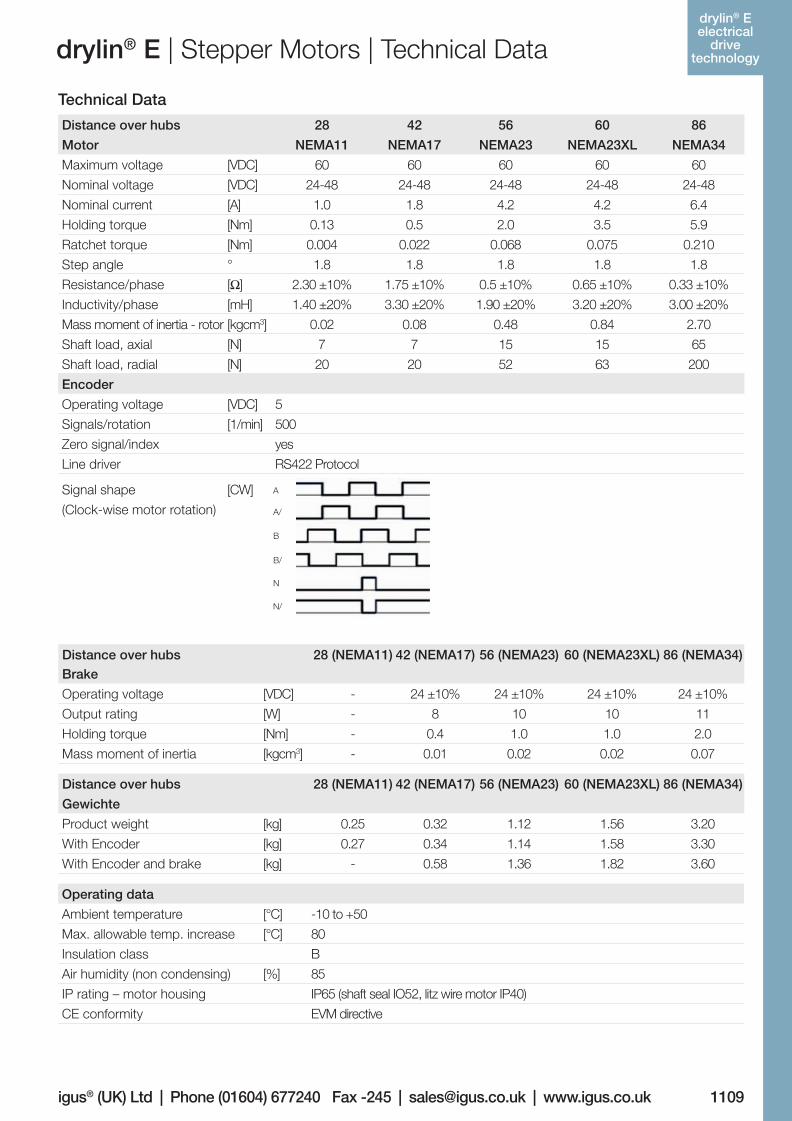
drylin® E | Stepper Motors | Technical Data
Technical Data
Distance over hubs 28 42 56 60 86
Motor NEMA11 NEMA17 NEMA23 NEMA23XL NEMA34
Maximum voltage [VDC] 60 60 60 60 60
Nominal voltage [VDC] 24-48 24-48 24-48 24-48 24-48
Nominal current [A] 1.0 1.8 4.2 4.2 6.4
Holding torque [Nm] 0.13 0.5 2.0 3.5 5.9
Ratchet torque [Nm] 0.004 0.022 0.068 0.075 0.210
Step angle ° 1.8 1.8 1.8 1.8 1.8
Resistance/phase [Ω] 2.30 ±10% 1.75 ±10% 0.5 ±10% 0.65 ±10% 0.33 ±10%
Inductivity/phase [mH] 1.40 ±20% 3.30 ±20% 1.90 ±20% 3.20 ±20% 3.00 ±20%
Mass moment of inertia - rotor [kgcm3] 0.02 0.08 0.48 0.84 2.70
Shaft load, axial [N] 7 7 15 15 65
Shaft load, radial [N] 20 20 52 63 200
Distance over hubs 28 (NEMA11) 42 (NEMA17) 56 (NEMA23) 60 (NEMA23XL) 86 (NEMA34)Brake
Operating voltage [VDC] - 24 ±10% 24 ±10% 24 ±10% 24 ±10%
Output rating [W] - 8 10 10 11
Holding torque [Nm] - 0.4 1.0 1.0 2.0
Mass moment of inertia [kgcm3] - 0.01 0.02 0.02 0.07
Operating data
Ambient temperature [°C] -10 to +50
Max. allowable temp. increase [°C] 80
Insulation class B
Air humidity (non condensing) [%] 85
IP rating – motor housing IP65 (shaft seal IO52, litz wire motor IP40)
CE conformity EVM directive
Distance over hubs 28 (NEMA11) 42 (NEMA17) 56 (NEMA23) 60 (NEMA23XL) 86 (NEMA34)
Gewichte
Product weight [kg] 0.25 0.32 1.12 1.56 3.20
With Encoder [kg] 0.27 0.34 1.14 1.58 3.30
With Encoder and brake [kg] - 0.58 1.36 1.82 3.60
Encoder
Operating voltage [VDC] 5
Signals/rotation [1/min] 500
Zero signal/index yes
Line driver RS422 Protocol
Signal shape
(Clock-wise motor rotation)
[CW]
A/
B
B/
N
N/
A
drylin® E electrical
drive technology
06_GL6_UK_drylin_Antrieb.indd 103 26.02.13 10:51
1110
drylin® SHT- Linear-
achsen
Lifetime calculation, CAD files and much more support www.igus.co.uk/en/drylinE
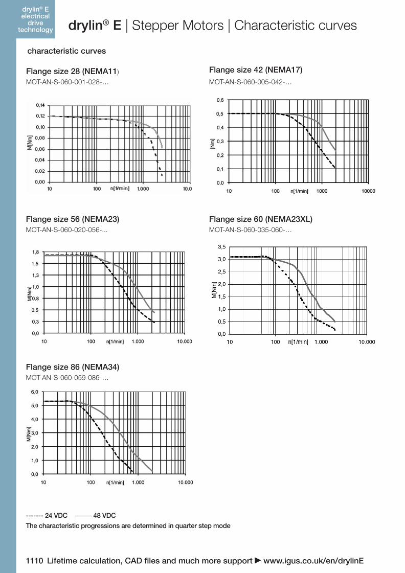
drylin® E | Stepper Motors | Characteristic curves
characteristic curves
Flange size 28 (NEMA11)
MOT-AN-S-060-001-028-…
Flange size 56 (NEMA23)MOT-AN-S-060-020-056-...
Flange size 60 (NEMA23XL)MOT-AN-S-060-035-060-…
Flange size 86 (NEMA34)MOT-AN-S-060-059-086-…
Flange size 42 (NEMA17)MOT-AN-S-060-005-042-…
------- 24 VDC 48 VDC
The characteristic progressions are determined in quarter step mode
drylin® E electrical
drive technology
06_GL6_UK_drylin_Antrieb.indd 104 26.02.13 10:51
Lifetime calculation, CAD files and much more support www.igus.co.uk/en/drylinE 1111
drylin® SHT- Linear-
achsen
igus® (UK) Ltd | Phone (01604) 677240 Fax -245 | [email protected] | www.igus.co.uk
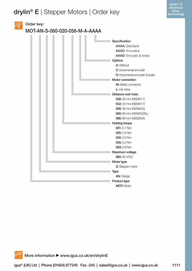
drylin® E | Stepper Motors | Order key
MOT-AN-S-060-020-056-M-A-AAAAOrder key:
Specification
AAAA: Standard
AAAC: Encoders
AAAD: Encoder & brake
Options
A: Without
C: Incremental encoder
D: Incremental encoder & brake
Motor connection
M: Metric connector
L: Litz wires
Distance over hubs
028: 28 mm (NEMA11)
042: 42 mm (NEMA17)
056: 56 mm (NEMA23)
060: 60 mm (NEMA23XL)
086: 86 mm (NEMA34)
Holding torque
001: 0.1 Nm
005: 0.5 Nm
020: 2.0 Nm
035: 3.5 Nm
059: 5.9 Nm
Maximum voltage
060: 60 V/DC
Motor type
S: Stepper motor
Type
AN: Design
Product type
MOT: Motor
More information www.igus.co.uk/en/drylinE
drylin® E electrical
drive technology
06_GL6_UK_drylin_Antrieb.indd 105 26.02.13 10:51
1112
drylin® SHT- Linear-
achsen
Lifetime calculation, CAD files and much more support www.igus.co.uk/en/drylinE
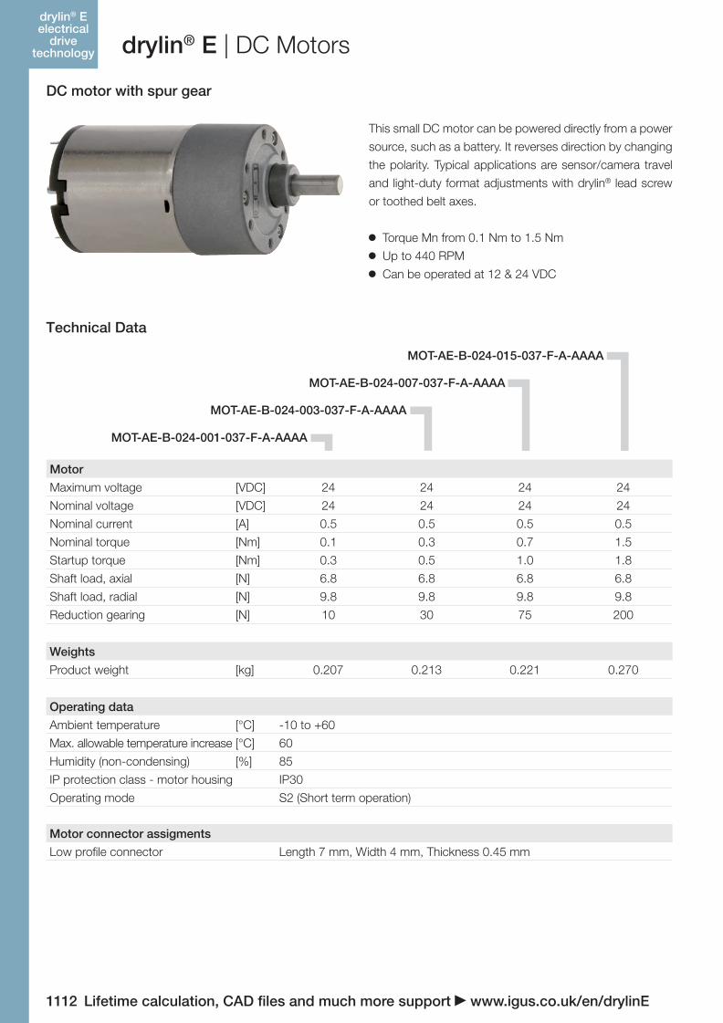
drylin® E | DC Motors
DC motor with spur gear
This small DC motor can be powered directly from a power
source, such as a battery. It reverses direction by changing
the polarity. Typical applications are sensor/camera travel
and light-duty format adjustments with drylin® lead screw
or toothed belt axes.
Torque Mn from 0.1 Nm to 1.5 Nm
Up to 440 RPM
Can be operated at 12 & 24 VDC
Motor
Maximum voltage [VDC] 24 24 24 24
Nominal voltage [VDC] 24 24 24 24
Nominal current [A] 0.5 0.5 0.5 0.5
Nominal torque [Nm] 0.1 0.3 0.7 1.5
Startup torque [Nm] 0.3 0.5 1.0 1.8
Shaft load, axial [N] 6.8 6.8 6.8 6.8
Shaft load, radial [N] 9.8 9.8 9.8 9.8
Reduction gearing [N] 10 30 75 200
Operating data
Ambient temperature [°C] -10 to +60
Max. allowable temperature increase [°C] 60
Humidity (non-condensing) [%] 85
IP protection class - motor housing IP30
Operating mode S2 (Short term operation)
Weights
Product weight [kg] 0.207 0.213 0.221 0.270
Motor connector assigments
Low profile connector Length 7 mm, Width 4 mm, Thickness 0.45 mm
Technical Data
MOT-AE-B-024-001-037-F-A-AAAA
MOT-AE-B-024-003-037-F-A-AAAA
MOT-AE-B-024-007-037-F-A-AAAA
MOT-AE-B-024-015-037-F-A-AAAA
drylin® E electrical
drive technology
06_GL6_UK_drylin_Antrieb.indd 106 26.02.13 10:51
Lifetime calculation, CAD files and much more support www.igus.co.uk/en/drylinE 1113
drylin® SHT- Linear-
achsen
igus® (UK) Ltd | Phone (01604) 677240 Fax -245 | [email protected] | www.igus.co.uk
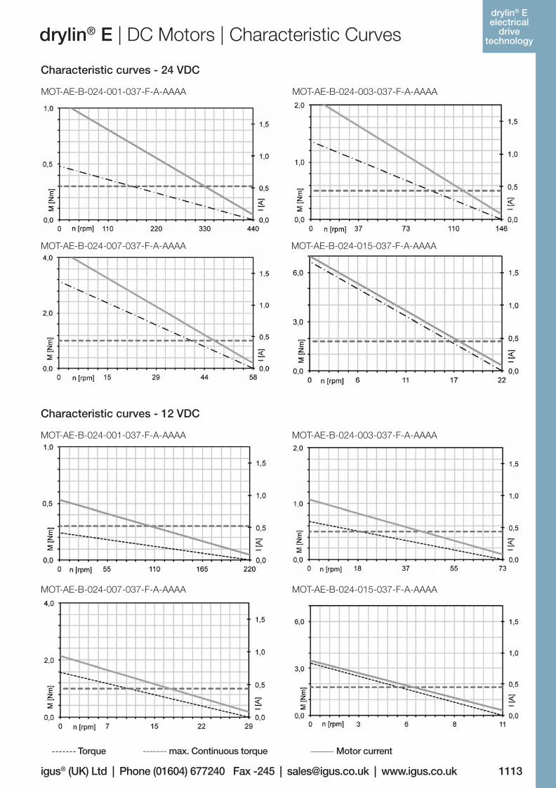
drylin® E | DC Motors | Characteristic Curves
Characteristic curves - 24 VDC
MOT-AE-B-024-001-037-F-A-AAAA
MOT-AE-B-024-001-037-F-A-AAAA
MOT-AE-B-024-007-037-F-A-AAAA
MOT-AE-B-024-007-037-F-A-AAAA
MOT-AE-B-024-015-037-F-A-AAAA
MOT-AE-B-024-015-037-F-A-AAAA
MOT-AE-B-024-003-037-F-A-AAAA
MOT-AE-B-024-003-037-F-A-AAAA
Characteristic curves - 12 VDC
Torque ------- max. Continuous torque Motor current
drylin® E electrical
drive technology
06_GL6_UK_drylin_Antrieb.indd 107 26.02.13 10:51
1114
drylin® SHT- Linear-
achsen
Lifetime calculation, CAD files and much more support www.igus.co.uk/en/drylinE
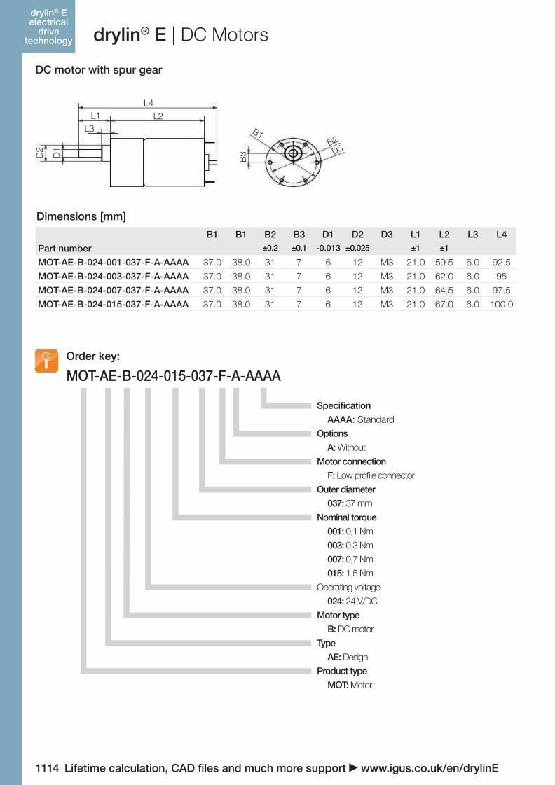
MOT-AE-B-024-015-037-F-A-AAAAOrder key:
DC motor with spur gear
Specification
AAAA: Standard
Options
A: Without
Motor connection
F: Low profile connector
Outer diameter
037: 37 mm
Nominal torque
001: 0,1 Nm
003: 0,3 Nm
007: 0,7 Nm
015: 1,5 Nm
Operating voltage
024: 24 V/DC
Motor type
B: DC motor
Type
AE: Design
Product type
MOT: Motor
drylin® E | DC Motors
B1 B1 B2 B3 D1 D2 D3 L1 L2 L3 L4
Part number ±0.2 ±0.1 -0.013 ±0.025 ±1 ±1
MOT-AE-B-024-001-037-F-A-AAAA 37.0 38.0 31 7 6 12 M3 21.0 59.5 6.0 92.5
MOT-AE-B-024-003-037-F-A-AAAA 37.0 38.0 31 7 6 12 M3 21.0 62.0 6.0 95
MOT-AE-B-024-007-037-F-A-AAAA 37.0 38.0 31 7 6 12 M3 21.0 64.5 6.0 97.5
MOT-AE-B-024-015-037-F-A-AAAA 37.0 38.0 31 7 6 12 M3 21.0 67.0 6.0 100.0
Dimensions [mm]
L4L2L1
L3
D1
D2
B3
B1B2D3
drylin® E electrical
drive technology
06_GL6_UK_drylin_Antrieb.indd 108 26.02.13 10:51