Embed Size (px)
Citation preview
8/3/2019 Drypoint M Brochure
http://slidepdf.com/reader/full/drypoint-m-brochure 1/4
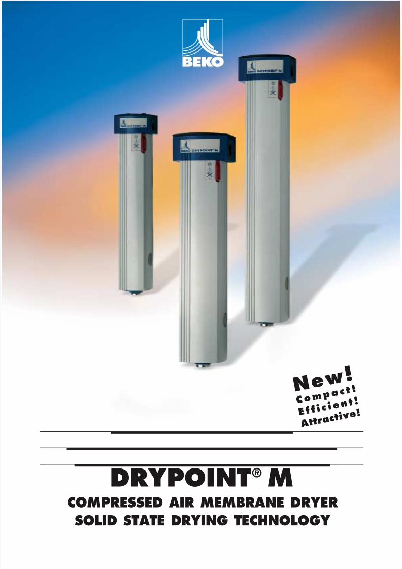
DRYPOINT® MCOMPRESSED AIR MEMBRANE DRYER
SOLID STATE DRYING TECHNOLOGY
N e w !
C o m p a c t !
E f f i c i e n t !
A t t r a c t i v e
!
8/3/2019 Drypoint M Brochure
http://slidepdf.com/reader/full/drypoint-m-brochure 2/4
DRYPOINT® M
DRYING TAILORED TO SIZE
It is most economical to dry only the compressed air that
is actually being used by the consumer, and to make it onlyas dry as he actually needs it to be. Thus the drying relatesthe specific individual application.
The compressed air user also makes demands with regard toimmediate availability and reliability. This applies whetherthe application is for laboratory areas, or an application inmanufacturing shops or outside areas, whether mobile orstationary.
The demand:
Application oriented compressed air drying.
The solution:DRYPOINT® M from BEKO.
DRYPOINT® M stands for compact efficiency …
• Low space requirement
• Simple, efficient and compatible withCLEARPOINT ® filters
• Smart design
… and safety …
• All functional components are safely integrated intothe housing
• Guaranteed drying, independent of the ambient conditions,humidity is removed regardless of external parameters
• No alteration of compressed air composition
… which pays off.
• lower purge air consumption
• Service-free, as there are no moving parts which maywear (only the pre-filter elements need to be changedat regular intervals)
• no environmentally hazardous drying agents
If you have any questions concerning a specific small orlarge capacity application, we are sure we can help youwith our experienced team of application engineers.
We recommend DRYPOINT ® M for application oriented
compressed air drying.
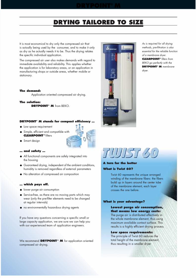
As is required for all drying
methods, pre-filtration is also essential for the reliable function
of a membrane dryer.
CLEARPOINT® filters from
BEKO go perfectly with the
DRYPOINT® M membrane
dryer.
A turn for the better
What is Twist 60?
Twist 60 represents the unique arrangedwinding of the membrane fibers: the fibersbuild up in layers around the center tubeof the membrane element, each layercrosses the one before.
What is your advantage?
Lowest purge air consumption,that means low energy costs:The purge air is distributed effectively inthe whole membrane element, thus usingmaximum available contact surface. Thisresults is a highly efficient drying process.
Low space requirements:The principle of Twist 60 reduces thetotal height of the membrane element,
thus resulting in a smaller dryer
8/3/2019 Drypoint M Brochure
http://slidepdf.com/reader/full/drypoint-m-brochure 3/4
DRYPOINT® M
SIMPLE AND EFFECTIVE
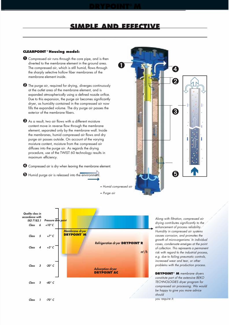
CLEARPOINT ® Housing model:
➊ Compressed air runs through the core pipe, and is thendiverted to the membrane element in the ground area.The compressed air, which is still humid, flows throughthe sharply selective hollow fiber membranes of themembrane element inside.
➋ The purge air, required for drying, diverges continuouslyat the outlet area of the membrane element, and isexpanded atmospherically using a defined nozzle orifice.Due to this expansion, the purge air becomes significantlydryer, as humidity contained in the compressed air nowfills the expanded volume. The dry purge air passes the
exterior of the membrane fibers.
➌ As a result, two air flows with a different moisturecontent move in reverse flow through the membraneelement, separated only by the membrane wall. Insidethe membranes, humid compressed air flows and drypurge air passes outside. On account of the varyingmoisture content, moisture from the compressed airdiffuses into the purge air. As regards the dryingprocedure, use of the TWIST 60 technology results inmaximum efficiency.
➍ Compressed air is dry when leaving the membrane element.
➎ Humid purge air is released into the environment.
Along with filtration, compressed air drying contributes significantly to the
enhancement of process reliability.Humidity in compressed air systemscauses corrosion, and promotes the growth of micro-organisms. In individual
cases, condensate emerges at the point of collection. This represents a permanent
risk with regard to the industrial process,e.g. due to failing pneumatic controls,increased wear and tear, or other
problems with the production process.
DRYPOINT® M membrane dryers
constitute part of the extensive BEKO TECHNOLOGIES dryer program for
compressed air processing. We would be happy to give you more advice should
you require it.
➍➊
= Humid compressed air
= Purge air
m 3 /h
Refrigeration dryer DRYPOINT® R
Membrane dryer DRYPOINT ®M
Adsorption dryer DRYPOINT® AC
Class 6 +10° C
Class 5 +7° C
Class 4 +3° C
Class 3 -20° C
Class 2 -40° C
Class 1 -70° C
➎
➋
➌
Pressure dew point
Quality class in accordance with
ISO 7183.1
8/3/2019 Drypoint M Brochure
http://slidepdf.com/reader/full/drypoint-m-brochure 4/4
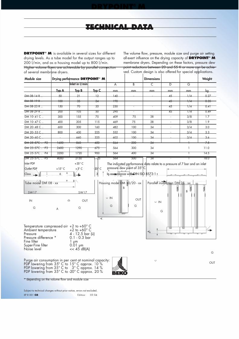
TECHNICAL DATA
Temperature compressed air +2 to +60° CAmbient temperature +2 to +60° CPressure 4 - 12.5 bar (ü)
Pressure difference * 0.1 - 0.3 barFine filter 1 µmSuper-Fine filter 0.01 µmNoise level << 45 dB(A)
Purge air consumption in per cent at nominal capacity:PDP lowering from 35° C to 15° C approx. 10 %PDP lowering from 35° C to 3° C approx. 14 %PDP lowering from 35° C to -20° C approx. 20 %
* depending on the volume flow and module size
DRYPOINT ® M is available in several sizes for different
drying levels. As a tube model for the output ranges up to200 l/min, and as a housing model up to 800 l/min.Higher volume flows are achievable by parallel connectionof several membrane dryers.
The volume flow, pressure, module size and purge air setting
all exert influence on the drying capacity of DRYPOINT®
Mmembrane dryers. Depending on these factors, pressure dewpoint reductions between 20 and 55 K or more can be achie-ved. Custom design is also offered for special applications.
Subject to technical changes without prior notice, errors not excluded.
XP R 001 GB Edition: 02.04
Tube model DM 08 - xx Housing model DM 10/20 - xx Parallel installation DM 25 - xx
SW17SW17
GGG
G
G
G
ININ
INOUT OUT
OUT
D
C
C
C
A
BB
A
A
DRYPOINT® M
Module size
The indicated performance data relate to a pressure of 7 bar and an inlet pressure dew point of 35° C.
Dimensions Weight
Typ A mm
DM 08-14 R ..
DM 08-19 R ..
DM 08-23 R ..
DM 08-29 R ..
DM 10- 41 C ..
DM 10- 47 C ..
DM 20- 48 C ..
DM 20- 53 C ..
DM 20- 60 C ..
DM 25-57C .. -P2
DM 25-57C .. -P3
DM 25-57C .. -P4
DM 25-57C .. -P5
Inlet PDP
Outlet PDP
Class
50
100
150
200
300
400
600
800
-
1600
2400
3200
4000
+15° C
6
21
35
70
105
155
205
300
430
660
860
1290
1720
2150
+35° C
+3° C
4
12
24
35
50
75
115
160
225
325
450
675
900
1125
-20° C
3
140
190
230
290
409
469
482
532
602
564
564
564
564
-
-
-
-
75
75
100
100
100
200
300
400
500
-
-
-
-
28
28
34
34
34
34
34
34
34
45
45
45
45
-
-
-
-
-
-
-
1/4
1/4
1/4
1/4
3/8
3/8
3/4
3/4
3/4
1
1
1
1
0.27
0.35
0.41
0.49
1.7
1.9
3.0
3.3
3.6
7.5
11.0
14.5
18.0
mm mm mm mm kg
A B C D G
Typ B Typ C
Drying performance DRYPOINT ® M
Inlet in l/min
In accordance with DIN ISO 8573-1