Embed Size (px)
Citation preview
DS 1083-029E LBT 8629
Mod.1083
SYSTEM BOOKLETNOTICE DE SYSTÈME
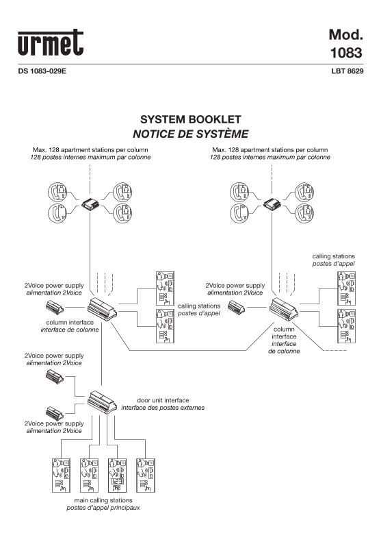
Max. 128 apartment stations per column128 postes internes maximum par colonne
Max. 128 apartment stations per column128 postes internes maximum par colonne
2Voice power supplyalimentation 2Voice
2Voice power supplyalimentation 2Voice
2Voice power supplyalimentation 2Voice
2Voice power supplyalimentation 2Voice
door unit interfaceinterface des postes externes
columninterfaceinterface
de colonne
column interfaceinterface de colonne
main calling stationspostes d’appel principaux
calling stationspostes d’appel
calling stationspostes d’appel
2 DS1083-029E
INDEX
GENERAL FEATURES AND SYSTEM TYPES ................................................................................................ 3
SYSTEM TYPOLOGIES .................................................................................................................................. 4
SYSTEM OPERATION .................................................................................................................................... 9 Call and busy state management ............................................................................................................... 9 Calling station functions ............................................................................................................................. 9
Video surveillance and access control functions ..................................................................................... 10 Apartment station performance ................................................................................................................ 10
ADDITIONAL FUNCTIONS ........................................................................................................................... 12 Staircase lights function ........................................................................................................................... 12
SYSTEM INSTALLATION ............................................................................................................................. 12 Standards and interference immunity ...................................................................................................... 12
Minimum and maximum number of devices ............................................................................................ 12 System power ........................................................................................................................................... 14 Allowed cables ......................................................................................................................................... 15 Maximum distances and extensions ........................................................................................................ 16
Electrical door lock connection ................................................................................................................ 27 Garage door control unit external relay connection ................................................................................. 27 Calling station auxiliary signal connection................................................................................................ 27 Apartment station signal connection ........................................................................................................ 27
Wiring and use of line terminations .......................................................................................................... 27
ACTIVATING THE SYSTEM.......................................................................................................................... 29 1 Line termination settings (z) .................................................................................................................. 29 2 Device confi guration .............................................................................................................................. 29 3 Power-on and power voltage test ......................................................................................................... 35 4 Check the system .................................................................................................................................. 35 5 Associating door unit buttons to users ................................................................................................. 36 6 Basic functional test .............................................................................................................................. 38 7 Optional programming for additional functions ..................................................................................... 38
TECHNICAL SPECIFICATIONS OF THE DEVICES ...................................................................................... 43
NOTES ON DIAGRAMS................................................................................................................................ 44
WIRING DIAGRAM ....................................................................................................................................... 89
ENGLISH
3DS1083-029E
The 2Voice video door phone system is easy to install. Only two non-polarised wires are needed to interconnect all system devices. It is modular and suitable for making from one- and two-family systems to large systems of various types (audio, video and mixed) and provide the best solution for all needs.
GENERAL FEATURES AND SYSTEM TYPESThe 2Voice video door phone system can be used to make video door phone systems with up to 127 users in each column, with up to 32 columns, each of which with up to 2 secondary calling stations. Up to 4 main calling stations and possibly one concierge switchboard may be present.
The features of the 2Voice video door phone system are:System
Possibility of managing up to 4 automatically switching main door units.Possibility of managing up to 32 columns, with up to 2 secondary calling stations each.Possibility of managing up to 128 apartment stations in each column with only one power unit.Possibility of managing up to 4 door units in parallel for each user.Possibility of connecting a concierge switchboard with typical functions to the system day/night function, lost call storage, etc.Use of only two non-polarised wires throughout the system.No local power supply is needed on calling stations or apartment stations.Extension wiring using 4-user distributor or in-out confi guration directly on the terminals of the devices.Extension short-circuit protection. Simplifi ed programming using dip-switches for apartment stations and for door units other Bluetooth connection for calling modules.Lock activation from all apartment stations, with programmable activation time and mode (free/privacy).Activation of a secondary lock (garage door) from all apartment stations.
Video surveillance and access controlPossibility of directly connecting either two cameras or fi ve cameras with the aid of an optional video switch to the calling stations (for calling stations with correct setup only).Door open indication by means of LEDs on apartment stations.Possibility of programming a 4-digit door opening code on calling modules (without time restraints) for each user and general codes with time restraints.
Calling stationsWith buttons (door units) or name director (calling modules).Current colour camera for video door phone call stations.Open door sensor.Up to 64 buttons can be connected to calling stations with buttons (door units) using 4 button expansion units.
Apartment stationsVideo door phone apartment stations with colour or black and white monitor, hands-free function and handset.Five door phone call tones (selectable by the user).Differentiated rings on same call tones according to origin (from main, from secondary, from intercom apartment station, from switchboard).Cyclic auto-on function for calling stations and surveillance camera stream (for calling stations with correct setup only).Calls to concierge switchboard.Freely programmable intercom call in column or apartment.Floor call button with differentiated call tone selectable by the user (5 possible call tones).Possibility of connecting, a fail-safe supplementary ringer or a calling repeater relay or a wireless call repeater to the apartment station for repeating all calls. Entrance door opening state display.
•••••
•••••
••
•
••
••••
•
••
•
••••
•
4 DS1083-029E
Additional functionsPossibility of switching on the staircase lights using a special decoder from the apartment stations, the door units and the switchboard.Possibility of connecting a video door phone messaging service in each column.Operating of audio repeater for hearing aid users in accordance with European Law SOCU0611477A.
StandardsIMQ and VDE certifi ed power unit.All devices comply with CE directives in the matter of electromagnetic compatibility and to the low voltage directive.The system is intrinsically protected from static and pulse electromagnetic interference.
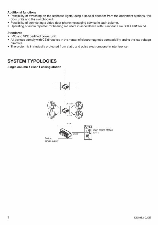
SYSTEM TYPOLOGIESSingle column 1 riser 1 calling station
TC
2Voicepower supply
LINE OUT
LINE IN
LINE 1
LINE 2
main calling stationID = 0
•
••
••
•
5DS1083-029E
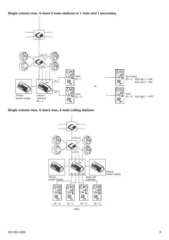
Single column max. 4 risers 2 main stations or 1 main and 1 secondary
TC
TC
2Voicepower supply
columninterfaceID = n
mainID = 1
or
mainID = 0
LINEIN1
IN0
321 4
LINE OUT
LINE IN
TC
TC
secondaryID = n AUX dip 1 = ON AUX dip 2 = ON
mainID = 0 AUX dip 1 = OFF
Single column max. 4 risers max. 4 main calling stations
2Voicepower supply
2Voicepower supply
door unitinterface
TC TC TC TC
LINE321 4
IN2IN1IN0 IN3
LINE OUT
LINE IN
Main
ID = 1 ID = 2 ID = 3ID = 0
6 DS1083-029E
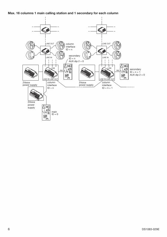
Max. 16 columns 1 main calling station and 1 secondary for each column
2Voicepower supply
2Voicepowersupply
columninterfaceID = n
columninterfaceID = n
secondaryID = n + 1AUX dip 2 = 0
secondaryID = nAUX dip 2 = 0
2Voicepower supply
mainID = 0
columninterfaceID = n + 1
TC
TC
TC
LINE321 4
LINE OUT
LINE IN
LINE IN
IN0
LINE OUT
LINE321 4
LINE OUT
LINE IN
LINE IN
IN0
LINE OUT
7DS1083-029E
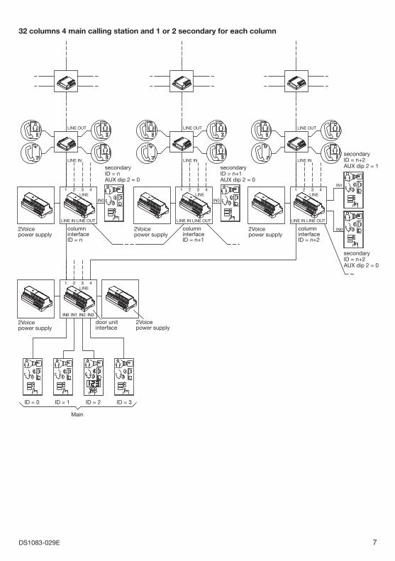
32 columns 4 main calling station and 1 or 2 secondary for each column
2Voicepower supply
columninterfaceID = n
2Voicepower supply
door unitinterface
2Voicepower supply
columninterfaceID = n+1
2Voicepower supply
columninterfaceID = n+2
secondaryID = n+2AUX dip 2 = 0
secondaryID = n+2AUX dip 2 = 1secondary
ID = n+1AUX dip 2 = 0
secondaryID = nAUX dip 2 = 0
TC TC
TC TC TCTC
TC
2Voicepower supply
LINE321 4
LINE321
IN0 IN1 IN2 IN3
4
LINE OUT
LINE IN
LINE IN
IN0
LINE OUT
LINE321 4
LINE OUT
LINE IN
LINE IN
IN0
LINE OUT
LINE321 4
LINE OUT
LINE IN
LINE IN
IN1
TC
IN0
LINE OUT
Main
ID = 1 ID = 2 ID = 3ID = 0
8 DS1083-029E
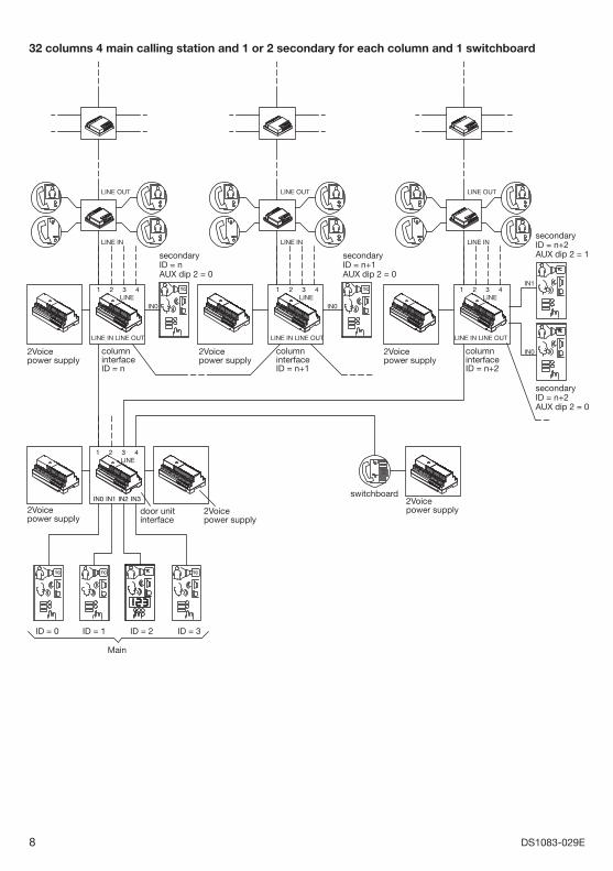
32 columns 4 main calling station and 1 or 2 secondary for each column and 1 switchboard
2Voicepower supply
columninterfaceID = n
2Voicepower supply
columninterfaceID = n+1
2Voicepower supply
columninterfaceID = n+2
2Voicepower supply
door unitinterface
2Voicepower supply
2Voicepower supply
switchboard
TC TC
TC TC TC
LINE321
IN0 IN1 IN2 IN3
4
LINE321 4
LINE OUT
LINE IN
LINE IN
IN0
LINE OUT
LINE321 4
LINE OUT
LINE IN
LINE IN LINE OUTLINE IN
IN0
LINE OUT
LINE321 4
LINE OUT
LINE IN
TC
IN1
TC
IN0
TC
secondaryID = n+2AUX dip 2 = 0
secondaryID = n+2AUX dip 2 = 1secondary
ID = n+1AUX dip 2 = 0
secondaryID = nAUX dip 2 = 0
Main
ID = 1 ID = 2 ID = 3ID = 0
9DS1083-029E
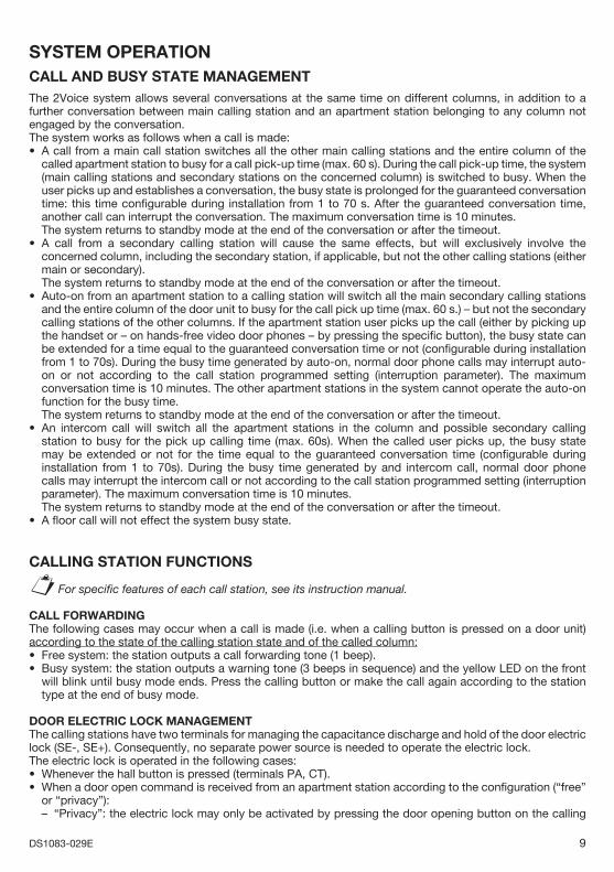
SYSTEM OPERATIONCALL AND BUSY STATE MANAGEMENTThe 2Voice system allows several conversations at the same time on different columns, in addition to a further conversation between main calling station and an apartment station belonging to any column not engaged by the conversation. The system works as follows when a call is made:
A call from a main call station switches all the other main calling stations and the entire column of the called apartment station to busy for a call pick-up time (max. 60 s). During the call pick-up time, the system (main calling stations and secondary stations on the concerned column) is switched to busy. When the user picks up and establishes a conversation, the busy state is prolonged for the guaranteed conversation time: this time confi gurable during installation from 1 to 70 s. After the guaranteed conversation time, another call can interrupt the conversation. The maximum conversation time is 10 minutes.
The system returns to standby mode at the end of the conversation or after the timeout.A call from a secondary calling station will cause the same effects, but will exclusively involve the concerned column, including the secondary station, if applicable, but not the other calling stations (either main or secondary).
The system returns to standby mode at the end of the conversation or after the timeout. Auto-on from an apartment station to a calling station will switch all the main secondary calling stations and the entire column of the door unit to busy for the call pick up time (max. 60 s.) – but not the secondary calling stations of the other columns. If the apartment station user picks up the call (either by picking up the handset or – on hands-free video door phones – by pressing the specifi c button), the busy state can be extended for a time equal to the guaranteed conversation time or not (confi gurable during installation from 1 to 70s). During the busy time generated by auto-on, normal door phone calls may interrupt auto-on or not according to the call station programmed setting (interruption parameter). The maximum conversation time is 10 minutes. The other apartment stations in the system cannot operate the auto-on function for the busy time.
The system returns to standby mode at the end of the conversation or after the timeout. An intercom call will switch all the apartment stations in the column and possible secondary calling station to busy for the pick up calling time (max. 60s). When the called user picks up, the busy state may be extended or not for the time equal to the guaranteed conversation time (confi gurable during installation from 1 to 70s). During the busy time generated by and intercom call, normal door phone calls may interrupt the intercom call or not according to the call station programmed setting (interruption parameter). The maximum conversation time is 10 minutes.
The system returns to standby mode at the end of the conversation or after the timeout. A fl oor call will not effect the system busy state.
CALLING STATION FUNCTIONS
For specifi c features of each call station, see its instruction manual.
CALL FORWARDINGThe following cases may occur when a call is made (i.e. when a calling button is pressed on a door unit) according to the state of the calling station state and of the called column:
Free system: the station outputs a call forwarding tone (1 beep).Busy system: the station outputs a warning tone (3 beeps in sequence) and the yellow LED on the front will blink until busy mode ends. Press the calling button or make the call again according to the station type at the end of busy mode.
DOOR ELECTRIC LOCK MANAGEMENTThe calling stations have two terminals for managing the capacitance discharge and hold of the door electric lock (SE-, SE+). Consequently, no separate power source is needed to operate the electric lock.The electric lock is operated in the following cases:
Whenever the hall button is pressed (terminals PA, CT).When a door open command is received from an apartment station according to the confi guration (“free” or “privacy”):
“Privacy”: the electric lock may only be activated by pressing the door opening button on the calling
•
•
•
•
•
§
••
••
–
10 DS1083-029E
station when an audio conversation has been established or when after having received a call or auto-on function either a video connection has been established or during the call pick-up time.“Free”: the electric lock may be activated by pressing the door opening button on the call station if this is confi gured as main or if this confi gured as secondary and the user belongs to the same column as the calling station. This function is typically used for secondary stations.
When a door open command is received from the switchboard.
Name tags, if powered by the ILL terminal of the apartment station will go out while the electric lock is actuated.
GARAGE DOOR LOCK MANAGEMENT The calling station have two terminals connected to the contacts of a normally open relay which can be used to control a gate opening control unit (1). The relay is operated for 1 second after receiving the garage door opening command according to the operating mode (“free” or “privacy”) as the door lock.
(1) The relay is not suitable to control direct power loads and can only be used as control relay. Refer to the calling station manual for electrical features.
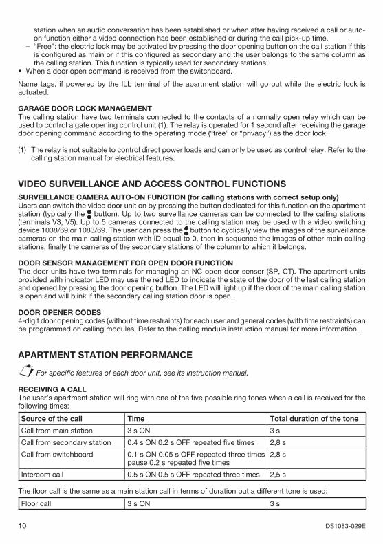
VIDEO SURVEILLANCE AND ACCESS CONTROL FUNCTIONSSURVEILLANCE CAMERA AUTO-ON FUNCTION (for calling stations with correct setup only)Users can switch the video door unit on by pressing the button dedicated for this function on the apartment station (typically the button). Up to two surveillance cameras can be connected to the calling stations (terminals V3, V5). Up to 5 cameras connected to the calling station may be used with a video switching device 1038/69 or 1083/69. The user can press the button to cyclically view the images of the surveillance cameras on the main calling station with ID equal to 0, then in sequence the images of other main calling stations, fi nally the cameras of the secondary stations of the column to which it belongs.
DOOR SENSOR MANAGEMENT FOR OPEN DOOR FUNCTIONThe door units have two terminals for managing an NC open door sensor (SP, CT). The apartment units provided with indicator LED may use the red LED to indicate the state of the door of the last calling station and opened by pressing the door opening button. The LED will light up if the door of the main calling station is open and will blink if the secondary calling station door is open.
DOOR OPENER CODES4-digit door opening codes (without time restraints) for each user and general codes (with time restraints) can be programmed on calling modules. Refer to the calling module instruction manual for more information.
APARTMENT STATION PERFORMANCE
For specifi c features of each door unit, see its instruction manual.
RECEIVING A CALLThe user’s apartment station will ring with one of the fi ve possible ring tones when a call is received for the following times:
Source of the call Time Total duration of the tone
Call from main station 3 s ON 3 s
Call from secondary station 0.4 s ON 0.2 s OFF repeated fi ve times 2,8 s
Call from switchboard 0.1 s ON 0.05 s OFF repeated three times pause 0.2 s repeated fi ve times
2,8 s
Intercom call 0.5 s ON 0.5 s OFF repeated three times 2,5 s
The fl oor call is the same as a main station call in terms of duration but a different tone is used:
Floor call 3 s ON 3 s
–
•
§
11DS1083-029E
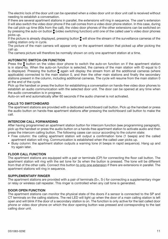
The electric lock of the door unit can be operated when a video door unit or door unit call is received without needing to establish a conversation.If there are several apartment stations in parallel, the extensions will ring in sequence. The user’s extension 0 will also switch the video door phone if the call comes from a video door phone station. In this case, during the call pick-up time (60s from the call), the video door phones of the other extensions can be switched on by pressing the auto-on button (video switching function) until one of the called user’s video door phones picks up.If the picture is already displayed, pressing button will show the stream of the surveillance cameras of the calling station only in cycle. The picture of the main camera will appear only on the apartment station that picked up after picking the call up.The camera picture will therefore be normally shown on only one apartment station at a time.
AUTOMATIC SWITCH-ON FUNCTIONPress the button on the video door phone to switch the auto-on function on if the apartment station is in stand-by. When the auto-on function is selected, the camera of the main station with ID equal to 0 is displayed. Pressing the button again will display the stream from all the additional cameras (where applicable) connected to the main station 0, and then the other main stations and fi nally the secondary stations present in the column, including additional cameras. The cycle will resume from the main station 0 at the end of the cycle.Pick up the handset or press the button for establishing a conversation on hands-free video door phones to establish an audio communication with the selected door unit. The door can be opened at any time when the audio conversation is in progress.Auto-on will end automatically after 60 seconds if the audio channel is not activated.
CALLS TO SWITCHBOARDThe apartment stations are provided with a dedicated switchboard call button. Pick up the handset or press the audio button on hands-free apartment stations after pressing the switchboard call button to make the call.
INTERCOM CALL FORWARDINGAfter having programmed an apartment station button for intercom function (see programming paragraph), pick up the handset or press the audio button on a hands-free apartment station to activate audio and then press the intercom calling button. The following cases can occur according to the column state:
Free column: the calling apartment station will output a confi rmation tone (1 beeps) and the called apartment station will ring. Communication is established when the called user picks up.Busy column: the apartment station outputs a warning tone (4 beeps in rapid sequence). Hang up and try again later.
FLOOR CALL FUNCTIONThe apartment stations are equipped with a pair or terminals (CP) for connecting the fl oor call button. The apartment station will ring with the set tone for 3s when the button is pressed. The tone will be different from that of the other calls. Connect this button to only one extension if there are extensions in parallel. The apartment stations will ring in sequence.
SUPPLEMENTARY RINGERThe apartment stations are provided with a pair of terminals (S+, S-) for connecting a supplementary ringer or relay or wireless call repeater. This ringer is controlled when any call tone is generated.
DOOR OPEN FUNCTIONThe apartment stations can monitor the physical state of the doors if a sensor is connected to the SP and CT terminals on the calling stations. The red LED will light up when the door of a main calling station is left open and will blink if the door of a secondary station is on. The function is only active for the last called door phone or video door phone on which the door opening button was pressed and corresponding to the last calling door unit.
•
•
12 DS1083-029E
ADDITIONAL FUNCTIONSSTAIRCASE LIGHTS FUNCTIONAn apartment station button can be programmed to switch the staircase lights on by means of a special decoder.
SYSTEM INSTALLATIONSTANDARDS AND INTERFERENCE IMMUNITYAll devices must be set up and wired according to rules of best practice and according to national installation standards. Particular attention must be devoted to power units and transformers: these must be arranged in suitable electric panels and equipped with appropriately dimensioned protection and circuit breaker switches.All devices comply with EC Standards with regards to electromagnetic compatibility and electrical safety. Furthermore, the power supply unit is IMQ and VDE certifi ed.
Satisfactory interference immunity can only be guaranteed if Urmet is used for bus line wiring.In all cases, to improve interference immunity, do not arrange the system wires near 110V, 230V and 400V power wires which generate strong electromagnetic fi elds.The following problems, typical of all video door phone system, the frequency and severity of which cannot be foreseen, may occur if these rules are not respected:
Data transmission errors between devices with consequent impossibility of making calls.Poor video quality: loss of details, double picture, etc.Video interference.Audio signal interference.
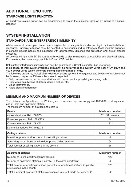
MINIMUM AND MAXIMUM NUMBER OF DEVICESThe minimum confi guration of the 2Voice system comprises: a power supply unit 1083/20A, a calling station and at least one apartment station.The maximum number of devices and users is:
Device Maximum number
4-user distributor Ref. 1083/55 32 x 32 columns
Power supply unit Ref. 1083/20A 34
Column interface Ref. 1083/50 32
Door unit interface Ref. 1083/75 1
Calling stations Maximum number
Main door phone or video door phone calling stations 4
Secondary door phone or video door phone calling stations 64
Total number of calling stations in the system 68
Apartment stations Maximum number
Number of users (apartments) per column 127
Number of apartment stations in parallel (in the same apartment) 4
Total number of apartment station per column (apartment stations in parallel are included in the count)
128
Total number of apartment stations connected in in-out mode per column (*) 32
••••
13DS1083-029E
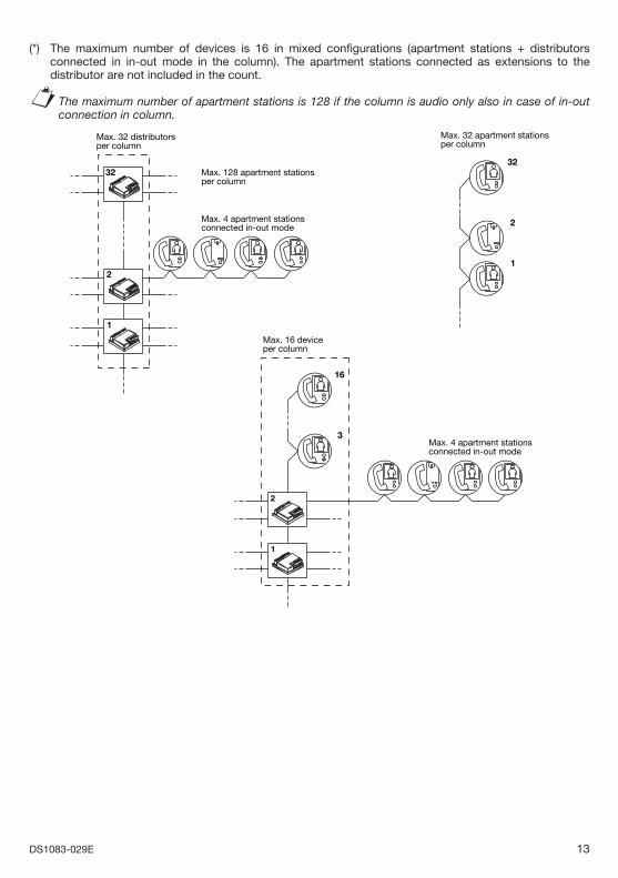
(*) The maximum number of devices is 16 in mixed confi gurations (apartment stations + distributors connected in in-out mode in the column). The apartment stations connected as extensions to the distributor are not included in the count.
The maximum number of apartment stations is 128 if the column is audio only also in case of in-out connection in column.
1
2
32 Max. 128 apartment stationsper column
Max. 4 apartment stationsconnected in-out mode
32
2
1
Max. 32 apartment stationsper column
Max. 32 distributorsper column
2
1
3
16
Max. 16 deviceper column
Max. 4 apartment stationsconnected in-out mode
§
14 DS1083-029E
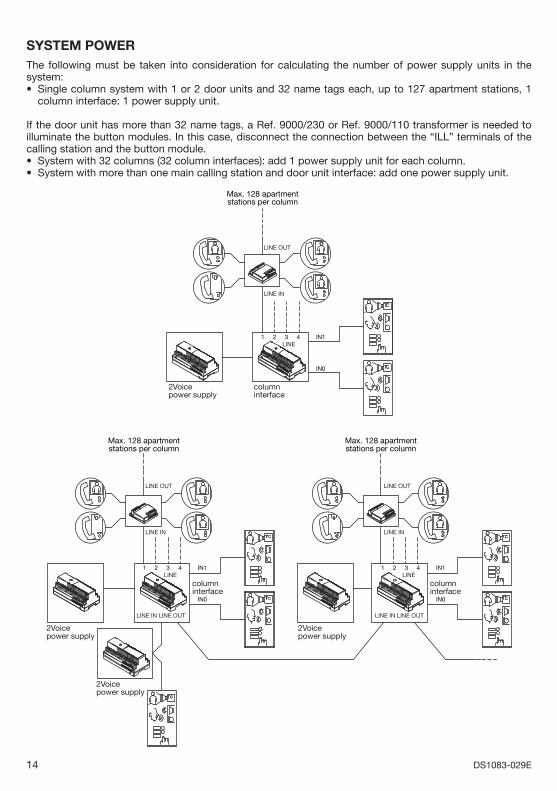
SYSTEM POWERThe following must be taken into consideration for calculating the number of power supply units in the system:
Single column system with 1 or 2 door units and 32 name tags each, up to 127 apartment stations, 1 column interface: 1 power supply unit.
If the door unit has more than 32 name tags, a Ref. 9000/230 or Ref. 9000/110 transformer is needed to illuminate the button modules. In this case, disconnect the connection between the “ILL” terminals of the calling station and the button module.
System with 32 columns (32 column interfaces): add 1 power supply unit for each column.System with more than one main calling station and door unit interface: add one power supply unit.
2Voicepower supply
columninterface
Max. 128 apartmentstations per column
LINE321 4 IN1
IN0
LINE OUT
LINE IN
Max. 128 apartmentstations per column
Max. 128 apartmentstations per column
2Voicepower supply
2Voicepower supply
columninterface
2Voicepower supply
LINE IN LINE OUT
columninterface
TC
TC
LINE321 4 IN1
IN0
LINE OUT
LINE IN
LINE IN LINE OUT
LINE321 4 IN1
IN0
LINE OUT
LINE IN
•
••
15DS1083-029E
Max. 128 apartmentstations per column
2Voicepower supply
2Voicepower supply
2Voicepower supply
columninterface
door unitinterface
Max. 128 apartmentstations per column
2Voicepower supply
columninterface
TCTC TC
TC
TC
TC
TC
LINE IN LINE OUT
LINE321 4 IN0
IN1
IN1 IN3IN2IN0
LINE OUT
LINE IN
LINE IN LINE OUT
LINE321 4 IN0
IN1
LINE OUT
LINE IN
TC
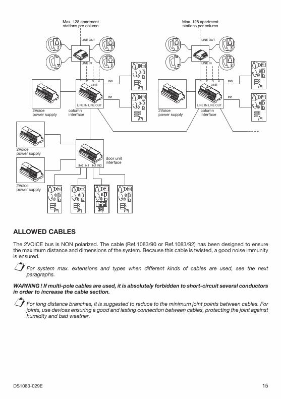
ALLOWED CABLES
The 2VOICE bus is NON polarized. The cable (Ref.1083/90 or Ref.1083/92) has been designed to ensure the maximum distance and dimensions of the system. Because this cable is twisted, a good noise immunity is ensured.
For system max. extensions and types when different kinds of cables are used, see the next paragraphs.
WARNING ! If multi-pole cables are used, it is absolutely forbidden to short-circuit several conductors in order to increase the cable section.
For long distance branches, it is suggested to reduce to the minimum joint points between cables. For joints, use devices ensuring a good and lasting connection between cables, protecting the joint against humidity and bad weather.
§
§
16 DS1083-029E
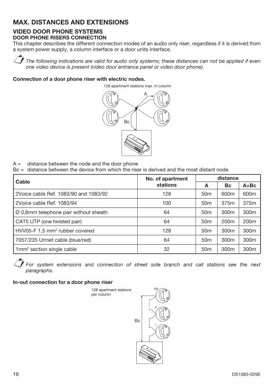
MAX. DISTANCES AND EXTENSIONSVIDEO DOOR PHONE SYSTEMSDOOR PHONE RISERS CONNECTION This chapter describes the different connection modes of an audio only riser, regardless if it is derived from a system power supply, a column interface or a door units interface.
The following indications are valid for audio only systems; these distances can not be applied if even one video device is present (video door entrance panel or video door phone).
Connection of a door phone riser with electric nodes.128 apartment stations max. in column
Bc
A
A = distance between the node and the door phone Bc = distance between the device from which the riser is derived and the most distant node
CableNo. of apartment
stationsdistance
A Bc A+Bc
2Voice cable Ref. 1083/90 and 1083/92 128 50m 600m 600m
2Voice cable Ref. 1083/94 100 50m 375m 375m
Ø 0,6mm telephone pair without sheath 64 50m 300m 300m
CAT5 UTP (one twisted pair) 64 50m 200m 200m
HVV05-F 1,5 mm2 rubber covered 128 50m 300m 300m
7057/235 Urmet cable (blue/red) 64 50m 300m 300m
1mm2 section single cable 32 50m 300m 300m
For system extensions and connection of street side branch and call stations see the next paragraphs.
In-out connection for a door phone riser128
2
1Bc
128 apartment stations per column
§
§
17DS1083-029E
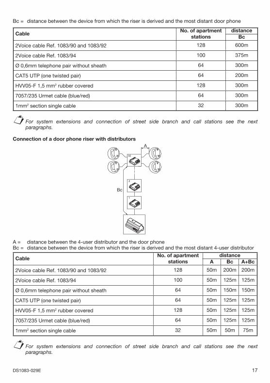
Bc = distance between the device from which the riser is derived and the most distant door phone
Cable No. of apartment
stationsdistance
Bc
2Voice cable Ref. 1083/90 and 1083/92 128 600m
2Voice cable Ref. 1083/94 100 375m
Ø 0,6mm telephone pair without sheath 64 300m
CAT5 UTP (one twisted pair) 64 200m
HVV05-F 1,5 mm2 rubber covered 128 300m
7057/235 Urmet cable (blue/red) 64 300m
1mm2 section single cable 32 300m
For system extensions and connection of street side branch and call stations see the next paragraphs.
Connection of a door phone riser with distributors
32
2
1
Bc
A
A = distance between the 4-user distributor and the door phone Bc = distance between the device from which the riser is derived and the most distant 4-user distributor
Cable No. of apartment
stationsdistance
A Bc A+Bc
2Voice cable Ref. 1083/90 and 1083/92 128 50m 200m 200m
2Voice cable Ref. 1083/94 100 50m 125m 125m
Ø 0,6mm telephone pair without sheath 64 50m 150m 150m
CAT5 UTP (one twisted pair) 64 50m 125m 125m
HVV05-F 1,5 mm2 rubber covered 128 50m 125m 125m
7057/235 Urmet cable (blue/red) 64 50m 125m 125m
1mm2 section single cable 32 50m 50m 75m
For system extensions and connection of street side branch and call stations see the next paragraphs.
§
§
18 DS1083-029E
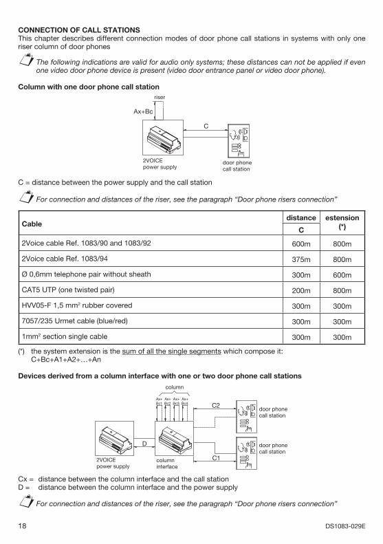
CONNECTION OF CALL STATIONS This chapter describes different connection modes of door phone call stations in systems with only one riser column of door phones
The following indications are valid for audio only systems; these distances can not be applied if even one video door phone device is present (video door entrance panel or video door phone).
Column with one door phone call station
Ax+Bc
C
riser
door phone call station
2VOICEpower supply
C = distance between the power supply and the call station
For connection and distances of the riser, see the paragraph “Door phone risers connection”
Cabledistance estension
(*)C
2Voice cable Ref. 1083/90 and 1083/92 600m 800m
2Voice cable Ref. 1083/94 375m 800m
Ø 0,6mm telephone pair without sheath 300m 600m
CAT5 UTP (one twisted pair) 200m 800m
HVV05-F 1,5 mm2 rubber covered 300m 300m
7057/235 Urmet cable (blue/red) 300m 300m
1mm2 section single cable 300m 300m
(*) the system extension is the sum of all the single segments which compose it: C+Bc+A1+A2+…+An
Devices derived from a column interface with one or two door phone call stationscolumn
Ax+Bc4
Ax+Bc3
Ax+Bc2
D
Ax+Bc1 C2
C12VOICEpower supply
columninterface
door phone call station
door phone call station
Cx = distance between the column interface and the call station D = distance between the column interface and the power supply
For connection and distances of the riser, see the paragraph “Door phone risers connection”
§
§
§
19DS1083-029E
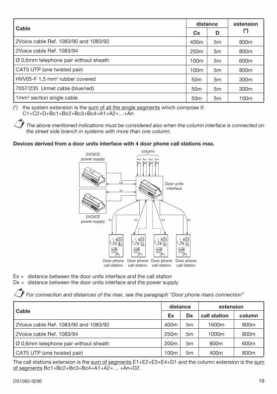
Cabledistance estension
(*)Cx D
2Voice cable Ref. 1083/90 and 1083/92 400m 5m 800m
2Voice cable Ref. 1083/94 250m 5m 800m
Ø 0,6mm telephone pair without sheath 100m 5m 600m
CAT5 UTP (one twisted pair) 100m 5m 800m
HVV05-F 1,5 mm2 rubber covered 50m 5m 300m
7057/235 Urmet cable (blue/red) 50m 5m 300m
1mm2 section single cable 50m 5m 150m
(*) the system extension is the sum of all the single segments which compose it: C1+C2+D+Bc1+Bc2+Bc3+Bc4+A1+A2+…+An
The above mentioned indications must be considered also when the column interface is connected on the street side branch in systems with more than one column.
Devices derived from a door units interface with 4 door phone call stations max.
D1
D2
E4E3E2E1
Ax+Bc1
Ax+Bc2
Ax+Bc3
Ax+Bc4
column
Door unitsinterface
2VOICEpower supply
2VOICEpower supply
Door phonecall station
Door phonecall station
Door phonecall station
Door phonecall station
Ex = distance between the door units interface and the call stationDx = distance between the door units interface and the power supply
For connection and distances of the riser, see the paragraph “Door phone risers connection”
Cabledistance estension
Ex Dx call station column
2Voice cable Ref. 1083/90 and 1083/92 400m 5m 1600m 800m
2Voice cable Ref. 1083/94 250m 5m 1000m 800m
Ø 0,6mm telephone pair without sheath 200m 5m 800m 600m
CAT5 UTP (one twisted pair) 100m 5m 400m 800m
The call stations extension is the sum of segments E1+E2+E3+E4+D1 and the column extension is the sum of segments Bc1+Bc2+Bc3+Bc4+A1+A2+… +An+D2.
§
§
20 DS1083-029E
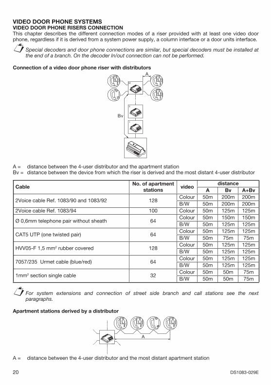
VIDEO DOOR PHONE SYSTEMSVIDEO DOOR PHONE RISERS CONNECTION This chapter describes the different connection modes of a riser provided with at least one video door phone, regardless if it is derived from a system power supply, a column interface or a door units interface.
Special decoders and door phone connections are similar, but special decoders must be installed at the end of a branch. On the decoder In/out connection can not be performed.
Connection of a video door phone riser with distributorsA
Bv1
2
32
A = distance between the 4-user distributor and the apartment station Bv = distance between the device from which the riser is derived and the most distant 4-user distributor
Cable No. of apartment
stationsvideo
distanceA Bv A+Bv
2Voice cable Ref. 1083/90 and 1083/92 128Colour 50m 200m 200mB/W 50m 200m 200m
2Voice cable Ref. 1083/94 100 Colour 50m 125m 125m
Ø 0,6mm telephone pair without sheath 64Colour 50m 150m 150mB/W 50m 125m 125m
CAT5 UTP (one twisted pair) 64Colour 50m 125m 125mB/W 50m 75m 75m
HVV05-F 1,5 mm2 rubber covered 128Colour 50m 125m 125mB/W 50m 125m 125m
7057/235 Urmet cable (blue/red) 64Colour 50m 125m 125mB/W 50m 125m 125m
1mm2 section single cable 32Colour 50m 50m 75mB/W 50m 50m 75m
For system extensions and connection of street side branch and call stations see the next paragraphs.
Apartment stations derived by a distributor
A
A = distance between the 4-user distributor and the most distant apartment station
§
§
21DS1083-029E
Cable No. of apartment
stationsdistance
A2Voice cable Ref. 1083/90 and 1083/92
Max 4 50m
2Voice cable Ref. 1083/94
Ø 0,6mm telephone pair without sheath
CAT5 UTP (one twisted pair)HVV05-F 1,5 mm2 rubber covered7057/235 Urmet cable (blue/red)1mm2 section single cable
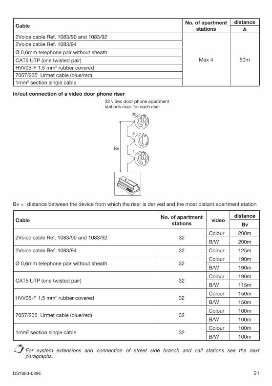
In/out connection of a video door phone riser32 video door phone apartment stations max. for each riser
Bv1
2
32
Bv = distance between the device from which the riser is derived and the most distant apartment station
Cable No. of apartment
stationsvideo
distance
Bv
2Voice cable Ref. 1083/90 and 1083/92 32Colour 200m
B/W 200m
2Voice cable Ref. 1083/94 32 Colour 125m
Ø 0,6mm telephone pair without sheath 32Colour 190m
B/W 190m
CAT5 UTP (one twisted pair) 32Colour 190m
B/W 115m
HVV05-F 1,5 mm2 rubber covered 32Colour 150m
B/W 150m
7057/235 Urmet cable (blue/red) 32Colour 100m
B/W 100m
1mm2 section single cable 32Colour 100m
B/W 100m
For system extensions and connection of street side branch and call stations see the next paragraphs.
§
22 DS1083-029E
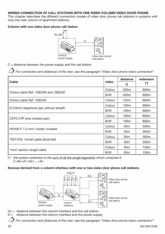
WIRING CONNECTION OF CALL STATIONS WITH ONE RISER COLUMN VIDEO DOOR PHONEThis chapter describes the different connection modes of video door phone call stations in systems with only one riser column of apartment stations.
Column with one video door phone call station
2VOICEpower supply
TC
Video door phone call station
riser
C
Ax+Bv
C = distance between the power supply and the call station
For connection and distances of the riser, see the paragraph “Video door phone risers connection”
Cable videodistance estension
(*)C
2Voice cable Ref. 1083/90 and 1083/92Colour 200m 800m
B/W 200m 800m
2Voice cable Ref. 1083/94 Colour 125m 800m
Ø 0,6mm telephone pair without sheathColour 100m 600m
B/W 100m 600m
CAT5 UTP (one twisted pair)Colour 100m 800m
B/W 100m 800m
HVV05-F 1,5 mm2 rubber coveredColour 50m 300m
B/W 50m 300m
7057/235 Urmet cable (blue/red)Colour 50m 300m
B/W 50m 300m
1mm2 section single cableColour 50m 150m
B/W 50m 150m
(*) the system extension is the sum of all the single segments which compose it: C+Bv+A1+A2+…+An
Devices derived from a column interface with one or two video door phone call stations
TC
columninterface
2VOICEpower supply
TC
Video door phone call station
Video door phone call station
C1
C2Ax+Bv1
D
Ax+Bv2
Ax+Bv3
Ax+Bv4
column
Cx = distance between the column interface and the call station D = distance between the column interface and the power supply
For connection and distances of the riser, see the paragraph “Video door phone risers connection”.
§
§
23DS1083-029E
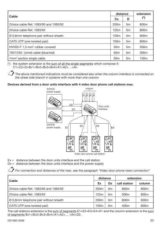
Cabledistance estension
(*)Cx D
2Voice cable Ref. 1083/90 and 1083/92 200m 5m 800m
2Voice cable Ref. 1083/94 125m 5m 800m
Ø 0,6mm telephone pair without sheath 100m 5m 600m
CAT5 UTP (one twisted pair) 100m 5m 800m
HVV05-F 1,5 mm2 rubber covered 50m 5m 300m
7057/235 Urmet cable (blue/red) 50m 5m 300m
1mm2 section single cable 50m 5m 150m
(*) the system extension is the sum of all the single segments which compose it: C1+C2+D+Bv1+Bv2+Bv3+Bv4+A1+A2+…+An
The above mentioned indications must be considered also when the column interface is connected on the street side branch in systems with more than one column.
Devices derived from a door units interface with 4 video door phone call stations max.2VOICEpower supply
2VOICEpower supply
TC
Door unitsinterface
TC TC TC
column
Ax+Bv4
Ax+Bv3
Ax+Bv2
Ax+Bv1
E1E2 E3
E4
D2
D1
Video door phone call station
Ex = distance between the door units interface and the call station Dx = distance between the door units interface and the power supply
For connection and distances of the riser, see the paragraph “Video door phone risers connection”
Cabledistance estension
Ex Dx call station column
2Voice cable Ref. 1083/90 and 1083/92 200m 5m 800m 800m
2Voice cable Ref. 1083/94 125m 5m 500m 800m
Ø 0,6mm telephone pair without sheath 200m 5m 800m 600m
CAT5 UTP (one twisted pair) 100m 5m 400m 800m
The call stations extension is the sum of segments E1+E2+E3+E4+D1 and the column extension is the sum of segments Bv1+Bv2+Bv3+Bv4+A1+A2+… +An+D2.
§
§
24 DS1083-029E
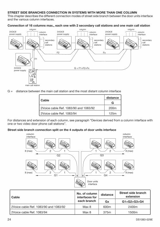
STREET SIDE BRANCHES CONNECTION IN SYSTEMS WITH MORE THAN ONE COLUMNThis chapter describes the different connection modes of street side branch between the door units interface and the various column interfaces.
Connection of 16 columns max., each one with 2 secondary call stations and one main call station
1
2VOICEpower supply
2VOICEpower supply
2VOICEpower supply
columninterface
columninterface
columninterface
2VOICEpower supply TC
secondarycallstations
secondarycallstations
secondarycallstations
F1
1
F2 Fx
G = F1+F2+Fx
main call station
1
column column column
G = distance between the main call station and the most distant column interface
Cabledistance
G
2Voice cable Ref. 1083/90 and 1083/92 200m
2Voice cable Ref. 1083/94 125m
For distances and extension of each column, see paragraph “Devices derived from a column interface with one or two video door phone call stations”.
Street side branch connection split on the 4 outputs of door units interface
1 2 8 (max)
2112
8 (max) 2 1
columninterface
columninterface
Door unitsinterface
8 (max)
G2
G1 G4
G3
8 (max)
CableNo. of column interfaces for each branch
distanceStreet side branch
extension
Gx G1+G2+G3+G4
2Voice cable Ref. 1083/90 and 1083/92 Max 8 600m 2400m
2Voice cable Ref. 1083/94 Max 8 375m 1500m
25DS1083-029E
For distances and extension of each column, see paragraph “Devices derived from a column interface with one or two video door phone call stations”.
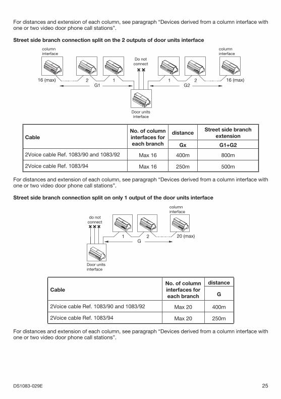
Street side branch connection split on the 2 outputs of door units interface
16 (max)G2G1
16 (max) 2 1
columninterface
columninterface
Do notconnect
1 2
Door unitsinterface
CableNo. of column interfaces for each branch
distanceStreet side branch
extension
Gx G1+G2
2Voice cable Ref. 1083/90 and 1083/92 Max 16 400m 800m
2Voice cable Ref. 1083/94 Max 16 250m 500m
For distances and extension of each column, see paragraph “Devices derived from a column interface with one or two video door phone call stations”.
Street side branch connection split on only 1 output of the door units interface
G20 (max)
Door unitsinterface
21
do notconnect
columninterface
CableNo. of column interfaces for each branch
distance
G
2Voice cable Ref. 1083/90 and 1083/92 Max 20 400m
2Voice cable Ref. 1083/94 Max 20 250m
For distances and extension of each column, see paragraph “Devices derived from a column interface with one or two video door phone call stations”.
26 DS1083-029E
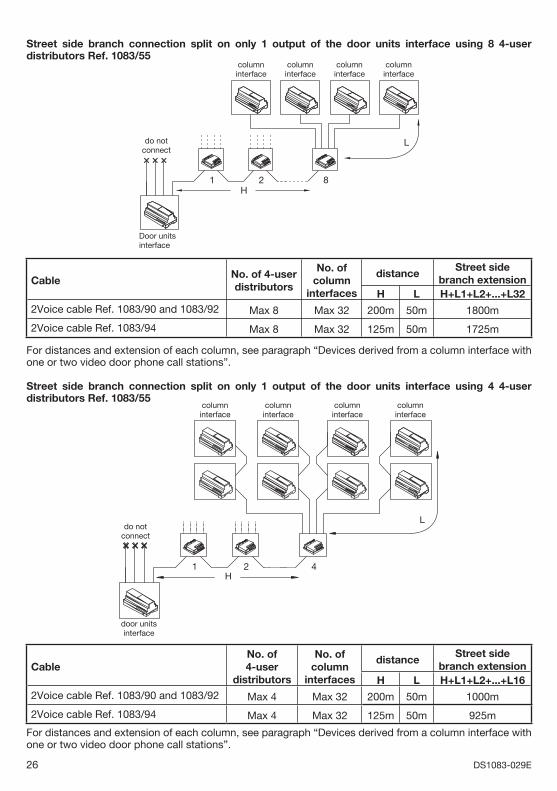
Street side branch connection split on only 1 output of the door units interface using 8 4-user distributors Ref. 1083/55
Door unitsinterface
do notconnect
columninterface
columninterface
columninterface
columninterface
L
1 2 8H
CableNo. of 4-user distributors
No. of column
interfaces
distanceStreet side
branch extensionH L H+L1+L2+...+L32
2Voice cable Ref. 1083/90 and 1083/92 Max 8 Max 32 200m 50m 1800m
2Voice cable Ref. 1083/94 Max 8 Max 32 125m 50m 1725m
For distances and extension of each column, see paragraph “Devices derived from a column interface with one or two video door phone call stations”.
Street side branch connection split on only 1 output of the door units interface using 4 4-user distributors Ref. 1083/55
door unitsinterface
21
do notconnect
L
H4
columninterface
columninterface
columninterface
columninterface
CableNo. of 4-user
distributors
No. of column
interfaces
distanceStreet side
branch extensionH L H+L1+L2+...+L16
2Voice cable Ref. 1083/90 and 1083/92 Max 4 Max 32 200m 50m 1000m
2Voice cable Ref. 1083/94 Max 4 Max 32 125m 50m 925m
For distances and extension of each column, see paragraph “Devices derived from a column interface with one or two video door phone call stations”.
27DS1083-029E
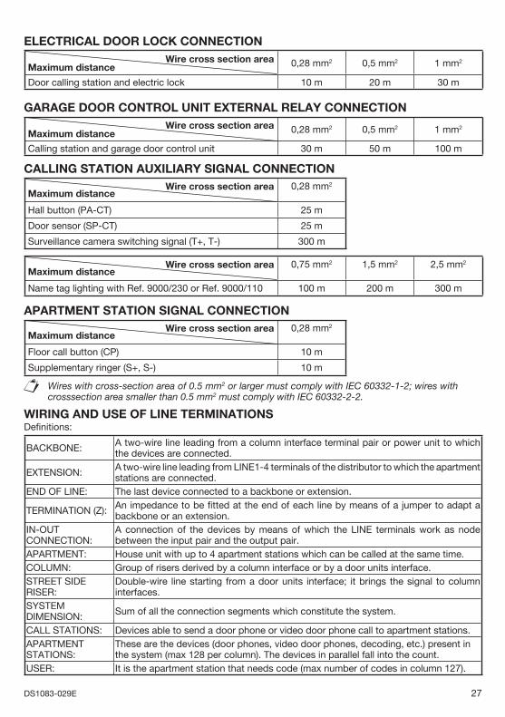
ELECTRICAL DOOR LOCK CONNECTION Wire cross section area
Maximum distance 0,28 mm2 0,5 mm2 1 mm2
Door calling station and electric lock 10 m 20 m 30 m
GARAGE DOOR CONTROL UNIT EXTERNAL RELAY CONNECTION Wire cross section area
Maximum distance 0,28 mm2 0,5 mm2 1 mm2
Calling station and garage door control unit 30 m 50 m 100 m CALLING STATION AUXILIARY SIGNAL CONNECTION
Wire cross section areaMaximum distance
0,28 mm2
Hall button (PA-CT) 25 m
Door sensor (SP-CT) 25 m
Surveillance camera switching signal (T+, T-) 300 m
Wire cross section areaMaximum distance
0,75 mm2 1,5 mm2 2,5 mm2
Name tag lighting with Ref. 9000/230 or Ref. 9000/110 100 m 200 m 300 m
APARTMENT STATION SIGNAL CONNECTION Wire cross section area
Maximum distance0,28 mm2
Floor call button (CP) 10 m
Supplementary ringer (S+, S-) 10 m
Wires with cross-section area of 0.5 mm2 or larger must comply with IEC 60332-1-2; wires with crosssection area smaller than 0.5 mm2 must comply with IEC 60332-2-2.
WIRING AND USE OF LINE TERMINATIONSDefi nitions:
BACKBONE: A two-wire line leading from a column interface terminal pair or power unit to which the devices are connected.
EXTENSION: A two-wire line leading from LINE1-4 terminals of the distributor to which the apartment stations are connected.
END OF LINE: The last device connected to a backbone or extension.
TERMINATION (Z): An impedance to be fi tted at the end of each line by means of a jumper to adapt a backbone or an extension.
IN-OUT CONNECTION:
A connection of the devices by means of which the LINE terminals work as node between the input pair and the output pair.
APARTMENT: House unit with up to 4 apartment stations which can be called at the same time.COLUMN: Group of risers derived by a column interface or by a door units interface.STREET SIDE RISER:
Double-wire line starting from a door units interface; it brings the signal to column interfaces.
SYSTEM DIMENSION: Sum of all the connection segments which constitute the system.
CALL STATIONS: Devices able to send a door phone or video door phone call to apartment stations.APARTMENT STATIONS:
These are the devices (door phones, video door phones, decoding, etc.) present in the system (max 128 per column). The devices in parallel fall into the count.
USER: It is the apartment station that needs code (max number of codes in column 127).
28 DS1083-029E
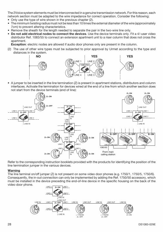
The 2Voice system elements must be interconnected in a genuine transmission network. For this reason, each network section must be adapted to the wire impedance for correct operation. Consider the following:
Only use the type of wire shown in the previous chapter (2).The minimum twisting radius must not be less than 10 times the external diameter of the wire (approximately 7cm) to prevent altering characteristics.Remove the sheath for the length needed to separate the pair in the two-wire line only.Do not add electrical nodes to connect the devices. Use the device terminals only. Fit a 4/-user video distributor Ref. 1083/55 to connect an extension apartment unit to a riser column that does not cross the apartment.
Exception: electric nodes are allowed if audio door phones only are present in the column.
(2) The use of other wire types must be subjected to prior approval by Urmet according to the type and distances in the system.
LINE 1
LINE 4
LINE 2
LINE 3
1083/55
NO YESYES
A jumper to be inserted in the line termination (Z) is present in apartment stations, distributors and column interfaces. Activate the termination for devices wired at the end of a line from which another section does not start from the device terminals (end of line):
Z= ON
Z= OFFLINE OUT
LINE IN
LINE 1LINE 3
LINE 4 LINE 2
Z= OFF
Z= ON
LINE 1LINE 3
LINE 4 LINE 2
Z= ON
LINE OUT
LINE IN
Z= OFF
LINEOUT
LINEIN
LINEOUT
LINEIN
LINEIN
LINE 1
LINE 4
LINE 2
LINE 3
Z= ON
Z= OFF
Z= OFF
Z= ON
Z= ON
Z= ON
Z= ON
LINE IN
Z= OFF Z= ON
1083/50LINE OUT LINE INLINE IN
Z= OFF
LINE OUT
From maincalling station
Refer to the corresponding instruction booklets provided with the products for identifying the position of the line termination jumper in the various devices.
WarningThe line terminal on/off jumper (Z) is not present on some video door phones (e.g. 1750/1, 1750/5, 1750/6).Consequently, the in-out connection can only be implemented by adding the Ref. 1750/50 accessory, which must be installed in the device preceding the end-of-line device in the specifi c housing on the back of the video door phone.
LINE IN
LINE OUT
LINE 1LINE 3
LINE 4 LINE 2
Z= ON
LINE IN
LINE 1 LINE INLINE IN LINE OUT
+ 1750/50Z= OFF
+ 1750/50Z= OFF
Z= ON
LINE 3
LINE 4 LINE 2
Z= OFF LINE IN LINE OUT LINE IN
••
••
•
29DS1083-029E
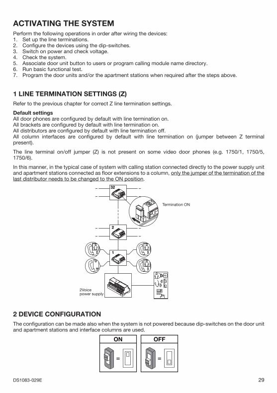
ACTIVATING THE SYSTEMPerform the following operations in order after wiring the devices:1. Set up the line terminations.2. Confi gure the devices using the dip-switches.3. Switch on power and check voltage.4. Check the system.5. Associate door unit button to users or program calling module name directory. 6. Run basic functional test.7. Program the door units and/or the apartment stations when required after the steps above.
1 LINE TERMINATION SETTINGS (Z) Refer to the previous chapter for correct Z line termination settings.
Default settingsAll door phones are confi gured by default with line termination on.All brackets are confi gured by default with line termination on.All distributors are confi gured by default with line termination off.All column interfaces are confi gured by default with line termination on (jumper between Z terminal present).
The line terminal on/off jumper (Z) is not present on some video door phones (e.g. 1750/1, 1750/5, 1750/6).
In this manner, in the typical case of system with calling station connected directly to the power supply unit and apartment stations connected as fl oor extensions to a column, only the jumper of the termination of the last distributor needs to be changed to the ON position.
2Voicepower supply
TC
32
2
1
Termination ON
2 DEVICE CONFIGURATION The confi guration can be made also when the system is not powered because dip-switches on the door unit and apartment stations and interface columns are used.
= =ONON
30 DS1083-029E
Particular care must be devoted to setting the device codes. Consider the following for correct system operation:
Each calling station in the system must have a univocal code (ID) which is set using the dip-switches to 0-3 for main stations and 0-31 for secondary stations. There may be two secondary stations with the same ID on the same column but with different address (see below for setting the address of a secondary station, values may be only 0 and 1).For secondary calling stations, the ID must coincide with the column ID set on the column interface. Each door unit must be characterised by a code (user code) set using dip-switches from 0 to 126 and a code (apartment station code) set using dip-switches from 0 to 3.The apartment station code must be 0 if there is one only station in the apartment. Up to 4 apartment stations can be connected in parallel: use the same user code and different apartment station codes. No two apartments in the same column may have the same user code. Each column interface must be characterised by a univocal code (column ID) set using the dip-switches from 0-31. Secondary door units in the column must have the same ID. All the apartment stations of a column acquire the column ID from the column interface. The column interface is not needed if there is only one column in the system and the column ID apartment stations will be 0. A column interface for each column is needed if the system has more than one column.The interface of all calling stations, apartment stations and columns must start from 0 and be consecutive.
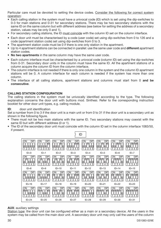
CALLING STATION CONFIGURATIONThe calling stations in the system must be univocally identifi ed according to the type. The following explanation concerns the door unit with buttons mod. Sinthesi. Refer to the corresponding instruction booklet for other door unit types, e.g. calling module.
ID: door unit identifi cationSet a number from 0 to 3 if the door unit is a main unit or from 0 to 31 if the door unit is a secondary unit as shown in the following fi gure.
There must not be two main stations with the same ID. Two secondary stations may coexist with the same ID but with different address (0 or 1).The ID of the secondary door unit must coincide with the column ID set in the column interface 1083/50, if present.
ID
ON DIP
4321 5
ID=0
ON DIP
4321 5
ID=1
ON DIP
4321 5
ID=2
ON DIP
4321 5
ID=3
ON DIP
4321 5
ID=4
ON DIP
4321 5
ID=5
ON DIP
4321 5
ID=6
ON DIP
4321 5
ID=7
ON DIP
4321 5
ID=8
ON DIP
4321 5
ID=9
ON DIP
4321 5
ID=10
ON DIP
4321 5
ID=11
ON DIP
4321 5
ID=12
ON DIP
4321 5
ID=13
ON DIP
4321 5
ID=14
ON DIP
4321 5
ID=15
ON DIP
4321 5
ID=16
ON DIP
4321 5
ID=17
ON DIP
4321 5
ID=18
ON DIP
4321 5
ID=19
ON DIP
4321 5
ID=20
ON DIP
4321 5
ID=21
ON DIP
4321 5
ID=22
ON DIP
4321 5
ID=23
ON DIP
4321 5
ID=24
ON DIP
4321 5
ID=25
ON DIP
4321 5
ID=26
ON DIP
4321 5
ID=27
ON DIP
4321 5
ID=28
ON DIP
4321 5
ID=29
ON DIP
4321 5
ID=30
ON DIP
4321 5
ID=31
AUX: auxiliary settingsStation type: the door unit can be confi gured either as a main or a secondary device. All the users in the system may be called from the main door unit. A secondary door unit may only call the users of the column
•
•
•
••
•
•
•
•
•
•
31DS1083-029E
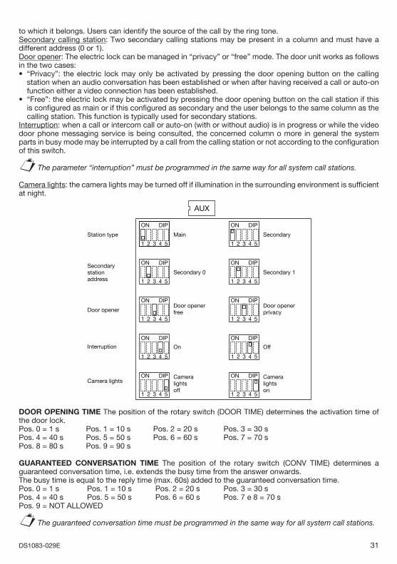
to which it belongs. Users can identify the source of the call by the ring tone. Secondary calling station: Two secondary calling stations may be present in a column and must have a different address (0 or 1).Door opener: The electric lock can be managed in “privacy” or “free” mode. The door unit works as follows in the two cases:
“Privacy”: the electric lock may only be activated by pressing the door opening button on the calling station when an audio conversation has been established or when after having received a call or auto-on function either a video connection has been established.“Free”: the electric lock may be activated by pressing the door opening button on the call station if this is confi gured as main or if this confi gured as secondary and the user belongs to the same column as the calling station. This function is typically used for secondary stations.
Interruption: when a call or intercom call or auto-on (with or without audio) is in progress or while the video door phone messaging service is being consulted, the concerned column o more in general the system parts in busy mode may be interrupted by a call from the calling station or not according to the confi guration of this switch.
The parameter “interruption” must be programmed in the same way for all system call stations.
Camera lights: the camera lights may be turned off if illumination in the surrounding environment is suffi cient at night.
AUX
ON DIP
4321 5
Main
ON DIP
4321 5
Secondary
ON DIP
4321 5
Secondary 0
ON DIP
4321 5
Secondary 1
ON DIP
4321 5
Door openerfree
ON DIP
4321 5
Door openerprivacy
ON DIP
4321 5
On
ON DIP
4321 5
Off
ON DIP
4321 5
Cameralightsoff
Station type
Secondarystationaddress
Door opener
Camera lightsON DIP
4321 5
Cameralightson
Interruption
DOOR OPENING TIME The position of the rotary switch (DOOR TIME) determines the activation time of the door lock.Pos. 0 = 1 s Pos. 1 = 10 s Pos. 2 = 20 s Pos. 3 = 30 sPos. 4 = 40 s Pos. 5 = 50 s Pos. 6 = 60 s Pos. 7 = 70 sPos. 8 = 80 s Pos. 9 = 90 s
GUARANTEED CONVERSATION TIME The position of the rotary switch (CONV TIME) determines a guaranteed conversation time, i.e. extends the busy time from the answer onwards.The busy time is equal to the reply time (max. 60s) added to the guaranteed conversation time.Pos. 0 = 1 s Pos. 1 = 10 s Pos. 2 = 20 s Pos. 3 = 30 sPos. 4 = 40 s Pos. 5 = 50 s Pos. 6 = 60 s Pos. 7 e 8 = 70 sPos. 9 = NOT ALLOWED
The guaranteed conversation time must be programmed in the same way for all system call stations.
•
•
§
§
32 DS1083-029E
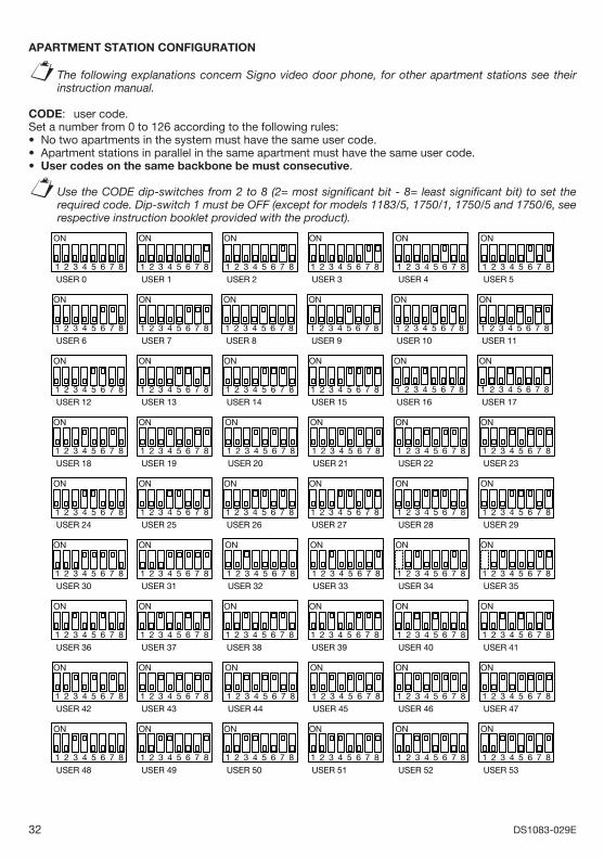
APARTMENT STATION CONFIGURATION
The following explanations concern Signo video door phone, for other apartment stations see their instruction manual.
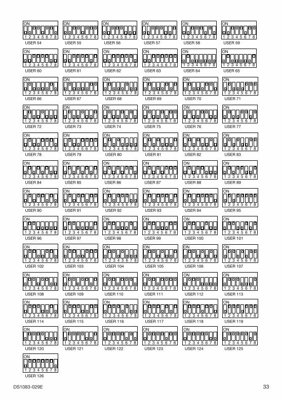
CODE: user code.Set a number from 0 to 126 according to the following rules:
No two apartments in the system must have the same user code.Apartment stations in parallel in the same apartment must have the same user code.User codes on the same backbone be must consecutive.
Use the CODE dip-switches from 2 to 8 (2= most signifi cant bit - 8= least signifi cant bit) to set the required code. Dip-switch 1 must be OFF (except for models 1183/5, 1750/1, 1750/5 and 1750/6, see respective instruction booklet provided with the product).
ON
USER 4
7654321 8
ON
USER 5
7654321 8
ON
USER 0
7654321 8
ON
USER 1
7654321 8
ON
USER 2
7654321 8
ON
USER 3
7654321 8
ON
USER 6
7654321 8
ON
USER 7
7654321 8
ON
USER 8
7654321 8
ON
USER 9
7654321 8
ON
USER 10
7654321 8
ON
USER 11
7654321 8
ON
USER 12
7654321 8
ON
USER 13
7654321 8
ON
USER 14
7654321 8
ON
USER 15
7654321 8
ON
USER 16
7654321 8
ON
USER 17
7654321 8
ON
USER 18
7654321 8
ON
USER 19
7654321 8
ON
USER 20
7654321 8
ON
USER 21
7654321 8
ON
USER 22
7654321 8
ON
USER 23
7654321 8
ON
USER 24
7654321 8
ON
USER 25
7654321 8
ON
USER 26
7654321 8
ON
USER 27
7654321 8
ON
USER 28
7654321 8
ON
USER 29
7654321 8
ON
USER 30
7654321 8
ON
USER 31
7654321 8
ON
USER 32
7654321 8
ON
USER 33
7654321 8
ON
USER 34
7654321 8
ON
USER 35
7654321 8
ON
USER 48
7654321 8
ON
USER 49
7654321 8
ON
USER 36
7654321 8
ON
USER 37
7654321 8
ON
USER 38
7654321 8
ON
USER 39
7654321 8
ON
USER 40
7654321 8
ON
USER 41
7654321 8
ON
USER 42
7654321 8
ON
USER 43
7654321 8
ON
USER 44
7654321 8
ON
USER 45
7654321 8
ON
USER 46
7654321 8
ON
USER 47
7654321 8
ON
USER 50
7654321 8
ON
USER 51
7654321 8
ON
USER 52
7654321 8
ON
USER 53
7654321 8
§
•••
§
33DS1083-029E
ON
USER 84
7654321 8
ON
USER 85
7654321 8
ON
USER 86
7654321 8
ON
USER 87
7654321 8
ON
USER 102
7654321 8
ON
USER 103
7654321 8
ON
USER 108
7654321 8
ON
USER 109
7654321 8
ON
USER 110
7654321 8
ON
USER 111
7654321 8
ON
USER 114
7654321 8
ON
USER 115
7654321 8
ON
USER 116
7654321 8
ON
USER 117
7654321 8
ON
USER 118
7654321 8
ON
USER 119
7654321 8
ON
USER 126
7654321 8
ON
USER 54
7654321 8
ON
USER 56
7654321 8
ON
USER 57
7654321 8
ON
USER 58
7654321 8
ON
USER 59
7654321 8
ON
USER 60
7654321 8
ON
USER 61
7654321 8
ON
USER 62
7654321 8
ON
USER 63
7654321 8
ON
USER 55
7654321 8
ON
USER 64
7654321 8
ON
USER 65
7654321 8
ON
USER 66
7654321 8
ON
USER 67
7654321 8
ON
USER 68
7654321 8
ON
USER 69
7654321 8
ON
USER 70
7654321 8
ON
USER 71
7654321 8
ON
USER 72
7654321 8
ON
USER 73
7654321 8
ON
USER 74
7654321 8
ON
USER 75
7654321 8
ON
USER 76
7654321 8
ON
USER 77
7654321 8
ON
USER 78
7654321 8
ON
USER 79
7654321 8
ON
USER 80
7654321 8
ON
USER 81
7654321 8
ON
USER 82
7654321 8
ON
USER 83
7654321 8
ON
USER 88
7654321 8
ON
USER 89
7654321 8
ON
USER 90
7654321 8
ON
USER 91
7654321 8
ON
USER 92
7654321 8
ON
USER 93
7654321 8
ON
USER 94
7654321 8
ON
USER 95
7654321 8
ON
USER 96
7654321 8
ON
USER 97
7654321 8
ON
USER 98
7654321 8
ON
USER 99
7654321 8
ON
USER 100
7654321 8
ON
USER 101
7654321 8
ON
USER 104
7654321 8
ON
USER 105
7654321 8
ON
USER 106
7654321 8
ON
USER 107
7654321 8
ON
USER 112
7654321 8
ON
USER 113
7654321 8
ON
USER 120
7654321 8
ON
USER 121
7654321 8
ON
USER 122
7654321 8
ON
USER 123
7654321 8
ON
USER 124
7654321 8
ON
USER 125
7654321 8
34 DS1083-029E
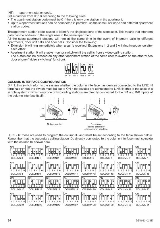
INT: apartment station code.Set a number from 0 to 3 according to the following rules:
The apartment station code must be 0 if there is only one station in the apartment.Up to 4 apartment stations can be connected in parallel: use the same user code and different apartment station codes.
The apartment station code is used to identify the single stations of the same user. This means that intercom calls can be address to the single user in the same apartment.All the users apartment stations will ring at the same time in the event of intercom calls to different apartments, door unit calls and fl oor calls. Consider the following:
Extension 0 will ring immediately when a call is received. Extensions 1, 2 and 3 will ring in sequence after each other.Apartment station 0 will enable monitor switch-on if the call is from a video calling station.
The button can be pressed on any other apartment station of the same user to switch on the other video door phone (“video switching” function).
21
INT 1
ON
21
INT 0
ON
21
INT 2
ON
21
INT 3
ON
COLUMN INTERFACE CONFIGURATIONDIP 1: this switch informs the system whether the column interface has devices connected to the LINE IN terminals or not: the switch must be set to ON if no devices are connected to LINE IN (this is the case of a simple system in which only one or two calling stations are directly connected to the IN1 and IN0 inputs of the column interface itself).
LINE IN LINE OUT
ON
1
From maincalling station or
other column interface
Not connected
LINE IN LINE OUT
ON
1
IN1
IN0
IN1
IN0
DIP 2 - 6: these are used to program the column ID and must be set according to the table shown below. Remember that the secondary calling station IDs directly connected to the column interface must coincide with the column ID shown here.
ON
COLUMN 0
654321
ON
COLUMN 1
654321
ON
COLUMN 2
654321
ON
COLUMN 3
654321
ON
COLUMN 4
654321
ON
COLUMN 5
654321
ON
COLUMN 6
654321
ON
COLUMN 7
654321
ON
COLUMN 8
654321
ON
COLUMN 9
654321
ON
COLUMN 10
654321
ON
COLUMN 11
654321
ON
COLUMN 12
654321
ON
COLUMN 13
654321
ON
COLUMN 14
654321
ON
COLUMN 15
654321
ON
COLUMN 24
654321
ON
COLUMN 25
654321
ON
COLUMN 26
654321
ON
COLUMN 27
654321
ON
COLUMN 28
654321
ON
COLUMN 29
654321
ON
COLUMN 30
654321
ON
COLUMN 31
654321
ON
COLUMN 16
654321
ON
COLUMN 17
654321
ON
COLUMN 18
654321
ON
COLUMN 19
654321
ON
COLUMN 20
654321
ON
COLUMN 21
654321
ON
COLUMN 22
654321
ON
COLUMN 23
654321
••
•
•
35DS1083-029E
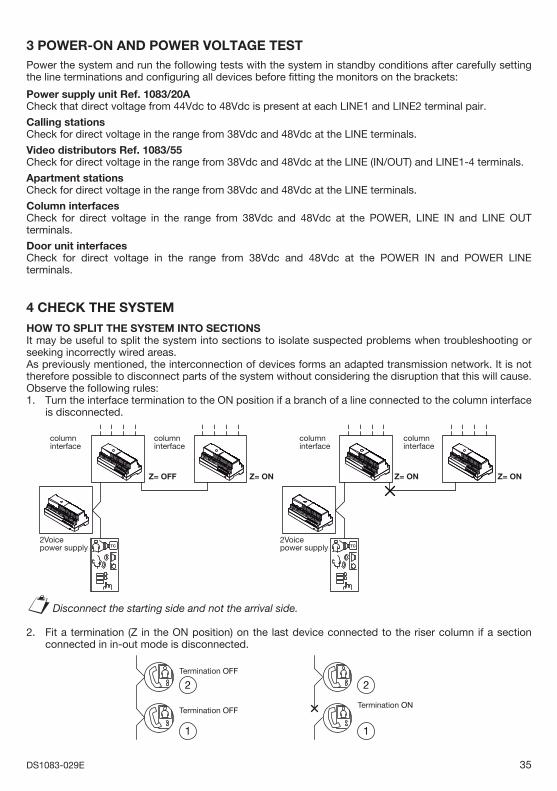
3 POWER-ON AND POWER VOLTAGE TEST Power the system and run the following tests with the system in standby conditions after carefully setting the line terminations and confi guring all devices before fi tting the monitors on the brackets:
Power supply unit Ref. 1083/20ACheck that direct voltage from 44Vdc to 48Vdc is present at each LINE1 and LINE2 terminal pair.
Calling stationsCheck for direct voltage in the range from 38Vdc and 48Vdc at the LINE terminals.
Video distributors Ref. 1083/55Check for direct voltage in the range from 38Vdc and 48Vdc at the LINE (IN/OUT) and LINE1-4 terminals.
Apartment stationsCheck for direct voltage in the range from 38Vdc and 48Vdc at the LINE terminals.
Column interfacesCheck for direct voltage in the range from 38Vdc and 48Vdc at the POWER, LINE IN and LINE OUT terminals.
Door unit interfacesCheck for direct voltage in the range from 38Vdc and 48Vdc at the POWER IN and POWER LINE terminals.
4 CHECK THE SYSTEM
HOW TO SPLIT THE SYSTEM INTO SECTIONS It may be useful to split the system into sections to isolate suspected problems when troubleshooting or seeking incorrectly wired areas.As previously mentioned, the interconnection of devices forms an adapted transmission network. It is not therefore possible to disconnect parts of the system without considering the disruption that this will cause. Observe the following rules:1. Turn the interface termination to the ON position if a branch of a line connected to the column interface
is disconnected.
TC TC2Voicepower supply
2Voicepower supply
Z= OFF
columninterface
columninterface
Z= ON
columninterface
Z= ON
columninterface
Z= ON
Disconnect the starting side and not the arrival side.
2. Fit a termination (Z in the ON position) on the last device connected to the riser column if a section connected in in-out mode is disconnected.
Termination OFF
Termination OFFTermination ON
11
22
§
36 DS1083-029E
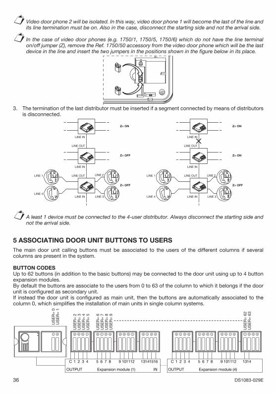
Video door phone 2 will be isolated. In this way, video door phone 1 will become the last of the line and its line termination must be on. Also in the case, disconnect the starting side and not the arrival side.
In the case of video door phones (e.g. 1750/1, 1750/5, 1750/6) which do not have the line terminal on/off jumper (Z), remove the Ref. 1750/50 accessory from the video door phone which will be the last device in the line and insert the two jumpers in the positions shown in the fi gure below in its place.
3. The termination of the last distributor must be inserted if a segment connected by means of distributors is disconnected.
LINE IN
LINE OUT
LINE IN
LINE OUTLINE 1
Z= ON
Z= OFF
Z= OFF
LINE INLINE 4
LINE 2
LINE 3
LINE IN
LINE OUT
LINE IN
LINE OUTLINE 1
Z= ON
Z= ON
Z= OFF
LINE INLINE 4
LINE 2
LINE 3
A least 1 device must be connected to the 4-user distributor. Always disconnect the starting side and not the arrival side.
5 ASSOCIATING DOOR UNIT BUTTONS TO USERSThe main door unit calling buttons must be associated to the users of the different columns if several columns are present in the system.
BUTTON CODESUp to 62 buttons (in addition to the basic buttons) may be connected to the door unit using up to 4 button expansion modules.By default the buttons are associate to the users from 0 to 63 of the column to which it belongs if the door unit is confi gured as secondary unit.If instead the door unit is confi gured as main unit, then the buttons are automatically associated to the column 0, which simplifi es the installation of main units in single column systems.
US
ER
= 2
US
ER
= 3
US
ER
= 0
US
ER
= 1
US
ER
= 4
US
ER
= 5
US
ER
= 6
US
ER
= 7
US
ER
= 8
US
ER
= 9
C 321 4 765 8 11109 12 151413 16
OUTPUT Expansion module (1) IN
US
ER
= 6
2U
SE
R=
63
C 321 4 765 8 11109 12 1413
OUTPUT Expansion module (4)
§
§
§
37DS1083-029E
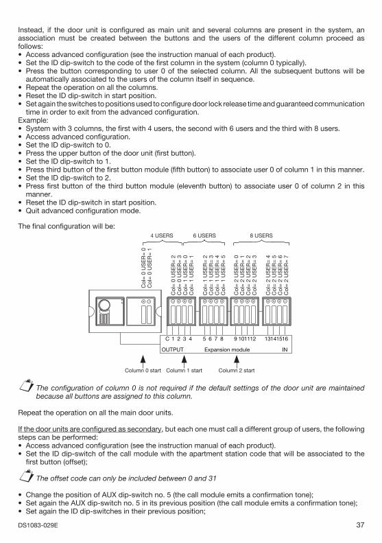
Instead, if the door unit is confi gured as main unit and several columns are present in the system, an association must be created between the buttons and the users of the different column proceed as follows:
Access advanced confi guration (see the instruction manual of each product).Set the ID dip-switch to the code of the fi rst column in the system (column 0 typically).Press the button corresponding to user 0 of the selected column. All the subsequent buttons will be automatically associated to the users of the column itself in sequence.Repeat the operation on all the columns.Reset the ID dip-switch in start position.Set again the switches to positions used to confi gure door lock release time and guaranteed communication time in order to exit from the advanced confi guration.
Example:System with 3 columns, the fi rst with 4 users, the second with 6 users and the third with 8 users.Access advanced confi guration.Set the ID dip-switch to 0.Press the upper button of the door unit (fi rst button).Set the ID dip-switch to 1.Press third button of the fi rst button module (fi fth button) to associate user 0 of column 1 in this manner.Set the ID dip-switch to 2.Press fi rst button of the third button module (eleventh button) to associate user 0 of column 2 in this manner.Reset the ID dip-switch in start position.Quit advanced confi guration mode.
The fi nal confi guration will be:
Col
= 0
US
ER
= 2
Col
= 0
US
ER
= 3
Col
= 0
US
ER
= 0
Col
= 0
US
ER
= 1
Col
= 1
US
ER
= 0
Col
= 1
US
ER
= 1
Col
= 1
US
ER
= 2
Col
= 1
US
ER
= 3
Col
= 1
US
ER
= 4
Col
= 1
US
ER
= 5
Col
= 2
US
ER
= 0
Col
= 2
US
ER
= 1
Col
= 2
US
ER
= 2
Col
= 2
US
ER
= 3
Col
= 2
US
ER
= 4
Col
= 2
US
ER
= 5
Col
= 2
US
ER
= 6
Col
= 2
US
ER
= 7
C 321 4 765 8 11109 12 151413 16
OUTPUT Expansion module IN
4 USERS 6 USERS 8 USERS
Column 0 start Column 1 start Column 2 start
The confi guration of column 0 is not required if the default settings of the door unit are maintained because all buttons are assigned to this column.
Repeat the operation on all the main door units.
If the door units are confi gured as secondary, but each one must call a different group of users, the following steps can be performed:
Access advanced confi guration (see the instruction manual of each product).Set the ID dip-switch of the call module with the apartment station code that will be associated to the fi rst button (offset);
The offset code can only be included between 0 and 31
Change the position of AUX dip-switch no. 5 (the call module emits a confi rmation tone);Set again the AUX dip-switch no. 5 in its previous position (the call module emits a confi rmation tone);Set again the ID dip-switches in their previous position;
•••
•••
••••••••
••
§
••
§•••
38 DS1083-029E
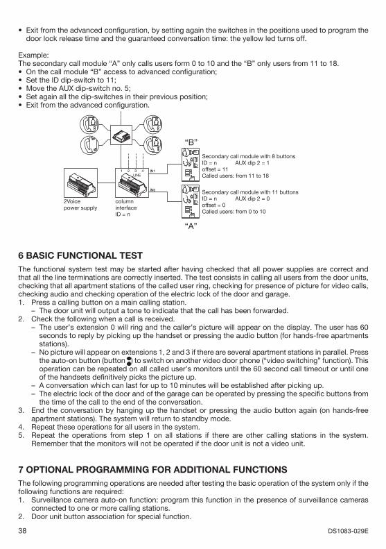
Exit from the advanced confi guration, by setting again the switches in the positions used to program the door lock release time and the guaranteed conversation time: the yellow led turns off.
Example: The secondary call module “A” only calls users form 0 to 10 and the “B” only users from 11 to 18.
On the call module “B” access to advanced confi guration;Set the ID dip-switch to 11;Move the AUX dip-switch no. 5;Set again all the dip-switches in their previous position;Exit from the advanced confi guration.
“B”
“A”
2Voicepower supply
columninterfaceID = n
Secondary call module with 8 buttonsID = n AUX dip 2 = 1offset = 11Called users: from 11 to 18
Secondary call module with 11 buttonsID = n AUX dip 2 = 0offset = 0Called users: from 0 to 10
6 BASIC FUNCTIONAL TESTThe functional system test may be started after having checked that all power supplies are correct and that all the line terminations are correctly inserted. The test consists in calling all users from the door units, checking that all apartment stations of the called user ring, checking for presence of picture for video calls, checking audio and checking operation of the electric lock of the door and garage. 1. Press a calling button on a main calling station.
The door unit will output a tone to indicate that the call has been forwarded.2. Check the following when a call is received.
The user’s extension 0 will ring and the caller’s picture will appear on the display. The user has 60 seconds to reply by picking up the handset or pressing the audio button (for hands-free apartments stations).No picture will appear on extensions 1, 2 and 3 if there are several apartment stations in parallel. Press the auto-on button (button ) to switch on another video door phone (“video switching” function). This operation can be repeated on all called user’s monitors until the 60 second call timeout or until one of the handsets defi nitively picks the picture up. A conversation which can last for up to 10 minutes will be established after picking up.The electric lock of the door and of the garage can be operated by pressing the specifi c buttons from the time of the call to the end of the conversation.
3. End the conversation by hanging up the handset or pressing the audio button again (on hands-free apartment stations). The system will return to standby mode.
4. Repeat these operations for all users in the system.5. Repeat the operations from step 1 on all stations if there are other calling stations in the system.
Remember that the monitors will not be operated if the door unit is not a video unit.
7 OPTIONAL PROGRAMMING FOR ADDITIONAL FUNCTIONSThe following programming operations are needed after testing the basic operation of the system only if the following functions are required:1. Surveillance camera auto-on function: program this function in the presence of surveillance cameras
connected to one or more calling stations.2. Door unit button association for special function.
•
•••••
–
–
–
––
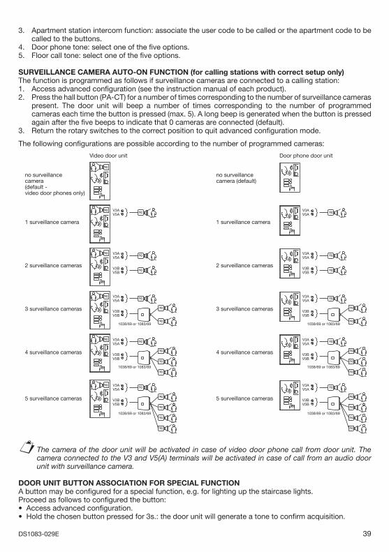
39DS1083-029E
3. Apartment station intercom function: associate the user code to be called or the apartment code to be called to the buttons.
4. Door phone tone: select one of the fi ve options. 5. Floor call tone: select one of the fi ve options.
SURVEILLANCE CAMERA AUTO-ON FUNCTION (for calling stations with correct setup only)The function is programmed as follows if surveillance cameras are connected to a calling station:1. Access advanced confi guration (see the instruction manual of each product). 2. Press the hall button (PA-CT) for a number of times corresponding to the number of surveillance cameras
present. The door unit will beep a number of times corresponding to the number of programmed cameras each time the button is pressed (max. 5). A long beep is generated when the button is pressed again after the fi ve beeps to indicate that 0 cameras are connected (default).
3. Return the rotary switches to the correct position to quit advanced confi guration mode.
The following confi gurations are possible according to the number of programmed cameras:
TC
TC
TC
TC
TC
TC
TC
TC
TC
TC
TC
TC
TC
TC
TC
TC
TC
TC
TC
TC
TC TC
TC
TC
TC
TC
TC
TC
TC
V3AV5A
V3AV5A
V3BV5B
V3AV5A
V3BV5B
V3AV5A
V3BV5B
V3AV5A
V3BV5B
TC
TC
TC
TC
TC
TC
TC
Video door unit Door phone door unit
no surveillancecamera(default -video door phones only)
2 surveillance cameras
3 surveillance cameras
4 surveillance cameras
1 surveillance camera
5 surveillance cameras
no surveillancecamera (default)
2 surveillance cameras
3 surveillance cameras
4 surveillance cameras
1 surveillance camera
5 surveillance cameras
V3AV5A
V3AV5A
V3BV5B
V3AV5A
V3BV5B
V3AV5A
V3BV5B
V3AV5A
V3BV5B
1038/69 or 1083/69
1038/69 or 1083/69
1038/69 or 1083/69
1038/69 or 1083/69
1038/69 or 1083/69
1038/69 or 1083/69
The camera of the door unit will be activated in case of video door phone call from door unit. The camera connected to the V3 and V5(A) terminals will be activated in case of call from an audio door unit with surveillance camera.
DOOR UNIT BUTTON ASSOCIATION FOR SPECIAL FUNCTION A button may be confi gured for a special function, e.g. for lighting up the staircase lights.Proceed as follows to confi gured the button:
Access advanced confi guration.Hold the chosen button pressed for 3s.: the door unit will generate a tone to confi rm acquisition.
§
••
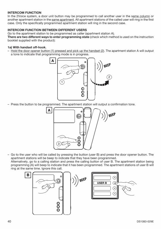
40 DS1083-029E
INTERCOM FUNCTION In the 2Voice system, a door unit button may be programmed to call another user in the same column or another apartment station in the same apartment. All apartment stations of the called user will ring in the fi rst case. Only the specifi cally programmed apartment station will ring in the second case.
INTERCOM FUNCTION BETWEEN DIFFERENT USERSGo to the apartment station to be programmed as caller (apartment station A).There are two different ways to enter programming state (check which method is used on the instruction booklet supplied with the product):
1a) With handset off-hook.Hold the door opener button (1) pressed and pick up the handset (2). The apartment station A will output a tone to indicate that programming mode is in progress.
BEEPA
2
1
Press the button to be programmed. The apartment station will output a confi rmation tone.
BEEPA
3
Go to the user who will be called by pressing the button (user B) and press the door opener button. The apartment stations will be beep to indicate that they have been programmed.
Alternatively, go to a calling station and press the calling button of user B. The apartment station being programming (A) will beep to indicate that it has been programmed. The apartment stations of user B will ring at the same time. Ignore this call.
BEEPB
USER B
–
–
–
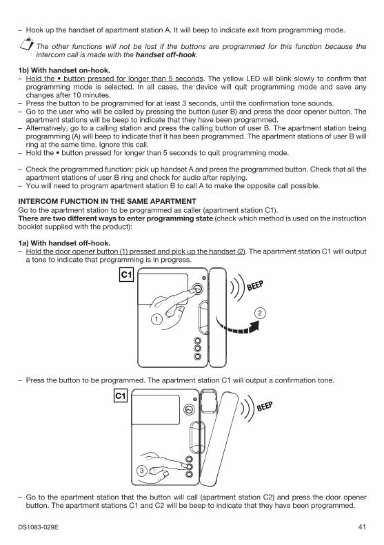
41DS1083-029E
Hook up the handset of apartment station A. It will beep to indicate exit from programming mode.
The other functions will not be lost if the buttons are programmed for this function because the intercom call is made with the handset off-hook.
1b) With handset on-hook.Hold the • button pressed for longer than 5 seconds. The yellow LED will blink slowly to confi rm that programming mode is selected. In all cases, the device will quit programming mode and save any changes after 10 minutes.Press the button to be programmed for at least 3 seconds, until the confi rmation tone sounds.Go to the user who will be called by pressing the button (user B) and press the door opener button. The apartment stations will be beep to indicate that they have been programmed.Alternatively, go to a calling station and press the calling button of user B. The apartment station being programming (A) will beep to indicate that it has been programmed. The apartment stations of user B will ring at the same time. Ignore this call.Hold the • button pressed for longer than 5 seconds to quit programming mode.
Check the programmed function: pick up handset A and press the programmed button. Check that all the apartment stations of user B ring and check for audio after replying.You will need to program apartment station B to call A to make the opposite call possible.
INTERCOM FUNCTION IN THE SAME APARTMENTGo to the apartment station to be programmed as caller (apartment station C1).There are two different ways to enter programming state (check which method is used on the instruction booklet supplied with the product):
1a) With handset off-hook.Hold the door opener button (1) pressed and pick up the handset (2). The apartment station C1 will output a tone to indicate that programming is in progress.
BEEPC1
21
Press the button to be programmed. The apartment station C1 will output a confi rmation tone.
BEEPC1
3
Go to the apartment station that the button will call (apartment station C2) and press the door opener button. The apartment stations C1 and C2 will be beep to indicate that they have been programmed.
–
§
–
––
–
–
–
–
–
–
–
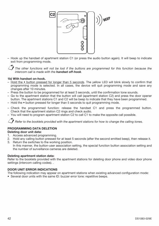
42 DS1083-029E
BEEPC2
Hook up the handset of apartment station C1 (or press the audio button again). It will beep to indicate exit from programming mode.
The other functions will not be lost if the buttons are programmed for this function because the intercom call is made with the handset off-hook.
1b) With handset on-hook.Hold the • button pressed for longer than 5 seconds. The yellow LED will blink slowly to confi rm that programming mode is selected. In all cases, the device will quit programming mode and save any changes after 10 minutes.Press the button to be programmed for at least 3 seconds, until the confi rmation tone sounds.Go to the apartment station that the button will call (apartment station C2) and press the door opener button. The apartment stations C1 and C2 will be beep to indicate that they have been programmed.Hold the • button pressed for longer than 5 seconds to quit programming mode.
Check the programmed function: release the handset C1 and press the programmed button. Check that the apartment station C2 rings and check audio.You will need to program apartment station C2 to call C1 to make the opposite call possible.
Refer to the booklets provided with the apartment stations for how to change the calling tones.
PROGRAMMING DATA DELETION Deleting door unit data:1. Access advanced programming.2. Hold any calling button pressed for at least 5 seconds (after the second emitted beep), then release it. 3. Return the switches to the working position. In this manner, the button-user association setting, the special function button association setting and
the number of surveillance cameras are deleted.
Deleting apartment station data:Refer to the booklets provided with the apartment stations for deleting door phone and video door phone settings (intercom calling codes). .
DOOR UNIT ERROR INDICATIONS The following indication may appear on apartment stations when existing advanced confi guration mode:
Several door units with the same ID: buzzer error tone: repetitive beeps.
–
§
–
––
–
–
–
§
•
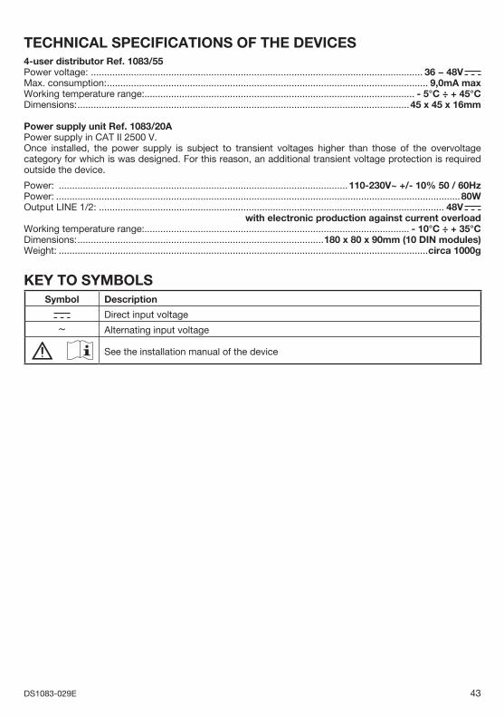
43DS1083-029E
TECHNICAL SPECIFICATIONS OF THE DEVICES4-user distributor Ref. 1083/55Power voltage: ............................................................................................................................ 36 − 48V Max. consumption: ........................................................................................................................ 9,0mA max Working temperature range:..................................................................................................... - 5°C ÷ + 45°CDimensions: ............................................................................................................................45 x 45 x 16mm
Power supply unit Ref. 1083/20APower supply in CAT II 2500 V. Once installed, the power supply is subject to transient voltages higher than those of the overvoltage category for which is was designed. For this reason, an additional transient voltage protection is required outside the device.
Power: ............................................................................................................110-230V~ +/- 10% 50 / 60HzPower: .......................................................................................................................................................80WOutput LINE 1/2: ................................................................................................................................. 48V with electronic production against current overloadWorking temperature range:................................................................................................... - 10°C ÷ + 35°CDimensions: ............................................................................................180 x 80 x 90mm (10 DIN modules)Weight: ..........................................................................................................................................circa 1000g
KEY TO SYMBOLSSymbol Description
Direct input voltage
~ Alternating input voltage
See the installation manual of the device
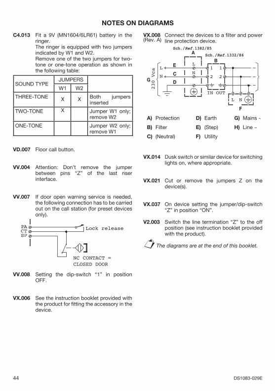
44 DS1083-029E
NOTES ON DIAGRAMS
C4.013 Fit a 9V (MN1604/6LR61) battery in the ringer.
The ringer is equipped with two jumpers indicated by W1 and W2.
Remove one of the two jumpers for two-tone or one-tone operation as shown in the following table:
SOUND TYPEJUMPERS
W1 W2
THREE-TONE X X Both jumpers inserted
TWO-TONE X Jumper W1 only; remove W2
ONE-TONE Jumper W2 only; remove W1
VD.007 Floor call button.
VV.004 Attention: Don’t remove the jumper between pins “Z” of the last riser interface.
VV.007 If door open warning service is needed, the following connection has to be carried out on the call station (for preset devices only).
Lock release
NC CONTACT =CLOSED DOOR
VV.008 Setting the dip-switch “1” in position OFF.
VX.006 See the instruction booklet provided with the product for fi tting the accessory in the device.
VX.008 Connect the devices to a fi lter and power line protection device.
Sch./Ref.1382/85
Sch./Ref.1332/86A
B
C
D
E
F
GH
A) Protection
B) Filter
C) (Neutral)
D) Earth
E) (Step)
F) Utility
G) Mains ~
H) Line ~
L
NL
N
NL
230
Vca
OUTIN
1 1
22
VX.014 Dusk switch or similar device for switching lights on, where appropriate.
VX.021 Cut or remove the jumpers Z on the device(s).
VX.037 On device setting the jumper/dip-switch “Z” in position “ON”.
V2.003 Switch the line termination “Z” to the off position (see instruction booklet provided with the product).
The diagrams are at the end of this booklet.§
(Rev. A)
45DS1083-029E
INDEX
CARACTERISTIQUES GENERALES ET TYPOLOGIES D’INSTALLATION .................................................. 46
TYPOLOGIES D’INSTALLATIONS ............................................................................................................... 47
FONCTIONNEMENT DU SYSTEME ............................................................................................................. 52Gestion des appels et de l’etat de ligne occupee ........................................................................................ 52
Prestations des potes externes ................................................................................................................ 52 Performances de vidéo surveillance et contrôle des accès ..................................................................... 53 Prestations des potes internes ................................................................................................................. 53
FONCTIONS ADDITIONNELLES .................................................................................................................. 55 Allumage de l’éclairage d’escalier ............................................................................................................ 55
INSTALLATION DU SYSTEME ..................................................................................................................... 56 Normes et immunité aux interférences ..................................................................................................... 56 Nombre minimum et maximum de dispositifs .......................................................................................... 56 Alimentation du systeme .......................................................................................................................... 57 Types de cables utilisables ...................................................................................................................... 59 Distances et extensions maximales ......................................................................................................... 60 Branchement de la serrure électrique passage pour piétons .................................................................. 71 Branchement du relais externe commande centrale passage pour véhicules ......................................... 71 Branchement des signaux auxiliares du poste externe ............................................................................ 71 Branchement des signaux des postes internes ....................................................................................... 71 Realisation des cablages et utilisation des terminaisons de ligne ........................................................... 71
ACTIVATION DU SYSTEME ......................................................................................................................... 73 1 Confi guration des terminaisons de ligne (z) ......................................................................................... 73 2 Confi guration des dispositifs ................................................................................................................. 73 3 Allumage et verifi cation de la tension d’alimentation ............................................................................ 79 4 Verifi cation de l’installation .................................................................................................................... 79 5 Association des touches des postes externes aux utilisateurs ............................................................. 80 6 Verifi cation du fonctionnement de base ................................................................................................ 82 7 Programmations facultatives pour les prestations supplementaires .................................................... 82
CARACTERISTIQUES TECHNIQUES DE DISPOSITIFS .............................................................................. 87
NOTES CONCERNANT LES SCHÉMAS ...................................................................................................... 88 EXAMPLE DE RACCORDEMENT................................................................................................................. 89
FRANÇAIS
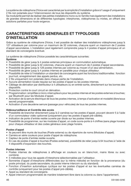
46 DS1083-029E
Le système de vidéophone 2Voice est caractérisé par la simplicité d’installation grâce à l’usage d’uniquement 2 fi ls non polarisés pour l’interconnexion de tous les dispositifs du système.Sa modularité permet de réaliser des petites installations mono ou bi-famille mais également des installations de grandes dimensions et de différentes typologies: interphones, vidéophones ou mixtes, en offrant des solutions parfaites pour toute exigence.
CARACTERISTIQUES GENERALES ET TYPOLOGIES D’INSTALLATIONGrâce au système de vidéophone 2Voice, il est possible de réaliser des installations vidéophones jusqu’à 127 utilisateurs par colonne pour un maximum de 32 colonnes, chacune ayant un maximum de 2 postes d’appel secondaires. L’installation peut également comprendre jusqu’à 4 postes d’appel principaux et un standard de conciergerie éventuel.
Le système de vidéophone 2Voice possède les caractéristiques suivantes:Système
Possibilité de gérer jusqu’à 4 postes externes principaux en commutation automatique.Possibilité de gérer jusqu’à 32 colonnes, chacune ayant un maximum de 2 postes d’appel secondaires.Possibilité de gérer jusqu’à 128 postes internes par colonne au moyen d’un seul alimentation.Possibilité de gérer jusqu’à 4 postes internes en parallèle pour chaque utilisateur.Possibilité de relier à l’installation un standard de conciergerie ayant les fonctions traditionnelles : fonction jour/nuit, enregistrement des appels perdus, etc.2 fi ls uniquement non polarisés dans chaque partie de l’installation.Aucune alimentation locale requise sur les postes d’appel ou les postes internes.Câblage de dérivation par distributeur à 4 utilisateurs ou en entrée-sortie, directement sur les bornes des dispositifs.Protection contre le court circuit en dérivation.Programmation: simplifi ée à micro-interrupteurs pour les postes internes et les postes externes à touches; par Bluetooth pour les Modules d’appel.Activation de la serrure électrique de tous les postes internes, à temps d’activation et modalité (libre/sous secret) programmable.Activation d’une deuxième serrure (passage pour véhicules) de tous les postes internes.
Vidéosurveillance et Contrôle des accèsPossibilité de brancher directement jusqu’à 2 caméras sur les postes d’appel, pouvant devenir 5 à l’aide d’un commutateur vidéo optionnel (uniquement pour les postes d’appel pré-câblés).Indication de porte d’entrée restée ouverte par diode sur les postes internes.Possibilité de programmer, sur les modules d’appel, un code ouvre-porte à 4 chiffres (sans plage horaire) pour chaque utilisateur et des codes généraux avec plage horaire.
Postes d’appelIls peuvent être munis de touches (Poste externe) ou de répertoire de noms (Modules d’appel).Caméra en série couleurs pour poste d’appel de vidéophone.Capteur de porte d’entrée restée ouverte.En cas de postes d’appel à touches (Postes externes), possibilité de relier jusqu’à 64 touches à l’aide de 4 dispositifs d’expansion des touches.
Postes internesPostes internes de vidéophones à affi chage en couleurs ou en blanc/noir, mains libres ou avec combiné.5 mélodies pour tous les appels d’interphone sélectionnables par l’utilisateur.Sonneries d’appel d’interphone différenciées (sur la même mélodie) en fonction de la provenance (du poste principal, du poste secondaire, du poste interne intercom ou du standard).Fonction d’insertion automatique cyclique sur les postes d’appel et sur les éventuelles caméras de contrôle (uniquement pour les postes d’appel pré-câblés).Appel au standard de conciergerie.Appel intercom programmable de manière totalement libre dans la colonne ou dans l’appartement.
•••••
•••
••
•
•
•
••
••••
•
••
•
••
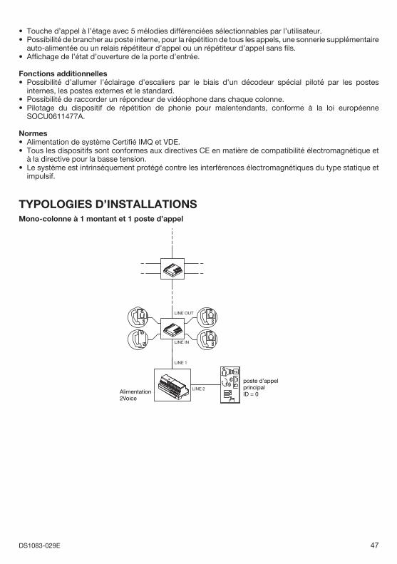
47DS1083-029E
Touche d’appel à l’étage avec 5 mélodies différenciées sélectionnables par l’utilisateur.Possibilité de brancher au poste interne, pour la répétition de tous les appels, une sonnerie supplémentaire auto-alimentée ou un relais répétiteur d’appel ou un répétiteur d’appel sans fi ls.Affi chage de l’état d’ouverture de la porte d’entrée.
Fonctions additionnellesPossibilité d’allumer l’éclairage d’escaliers par le biais d’un décodeur spécial piloté par les postes internes, les postes externes et le standard. Possibilité de raccorder un répondeur de vidéophone dans chaque colonne.Pilotage du dispositif de répétition de phonie pour malentendants, conforme à la loi européenne SOCU0611477A.
NormesAlimentation de système Certifi é IMQ et VDE.Tous les dispositifs sont conformes aux directives CE en matière de compatibilité électromagnétique et à la directive pour la basse tension.Le système est intrinsèquement protégé contre les interférences électromagnétiques du type statique et impulsif.
TYPOLOGIES D’INSTALLATIONSMono-colonne à 1 montant et 1 poste d’appel
TC
Alimentation2Voice
LINE OUT
LINE IN
LINE 1
LINE 2
poste d’appelprincipalID = 0
••
•
•
••
••
•
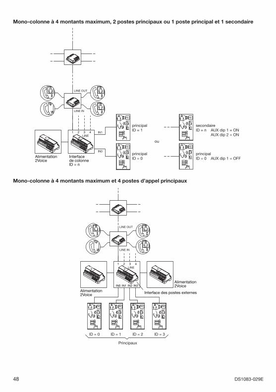
48 DS1083-029E
Mono-colonne à 4 montants maximum, 2 postes principaux ou 1 poste principal et 1 secondaire
TC
TC
Alimentation2Voice
Interfacede colonneID = n
LINEIN1
IN0
321 4
LINE OUT
LINE IN
ouTC
TC
secondaireID = n AUX dip 1 = ON AUX dip 2 = ON
principalID = 1
principalID = 0
principalID = 0 AUX dip 1 = OFF
Mono-colonne à 4 montants maximum et 4 postes d’appel principaux
Alimentation2Voice
Alimentation2Voice
Interface des postes externes
TC TC TC TC
LINE321 4
IN2IN1IN0 IN3
LINE OUT
LINE IN
Principaux
ID = 1 ID = 2 ID = 3ID = 0
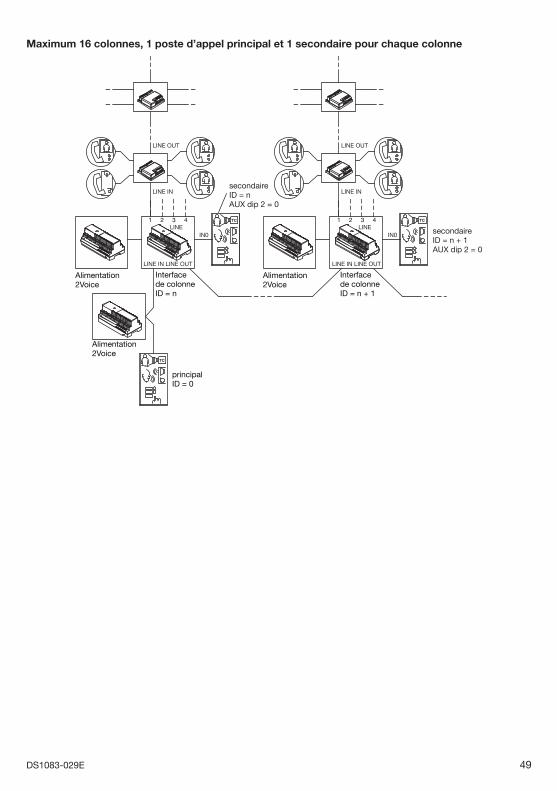
49DS1083-029E
Maximum 16 colonnes, 1 poste d’appel principal et 1 secondaire pour chaque colonne
Alimentation2Voice
Alimentation2Voice
principalID = 0
Interfacede colonneID = n
Alimentation2Voice
Interfacede colonneID = n + 1
TC
TC
TC
LINE321 4
LINE OUT
LINE IN
LINE IN
IN0
LINE OUT
LINE321 4
LINE OUT
LINE IN
LINE IN
IN0
LINE OUT
secondaireID = n + 1AUX dip 2 = 0
secondaireID = nAUX dip 2 = 0
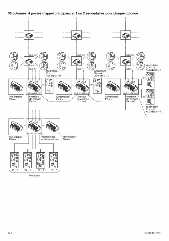
50 DS1083-029E
32 colonnes, 4 postes d’appel principaux et 1 ou 2 secondaires pour chaque colonne
Alimentation2Voice
Interfacede colonneID = n
Alimentation2Voice
Interface despostes externes
Alimentation2Voice
Interfacede colonneID = n+1
Principaux
ID = 1 ID = 2 ID = 3ID = 0
Alimentation2Voice
Interfacede colonneID = n+2
secondaireID = n+2AUX dip 2 = 1secondaire
ID = n+1AUX dip 2 = 0
secondaireID = nAUX dip 2 = 0
secondaireID = n+2AUX dip 2 = 0
TC TC
TC TC TCTC
TC
Alimentation2Voice
LINE321 4
LINE321
IN0 IN1 IN2 IN3
4
LINE OUT
LINE IN
LINE IN
IN0
LINE OUT
LINE321 4
LINE OUT
LINE IN
LINE IN
IN0
LINE OUT
LINE321 4
LINE OUT
LINE IN
LINE IN
IN1
TC
IN0
LINE OUT
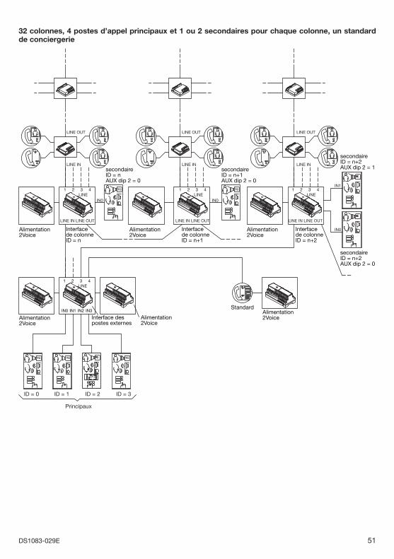
51DS1083-029E
32 colonnes, 4 postes d’appel principaux et 1 ou 2 secondaires pour chaque colonne, un standard de conciergerie
Alimentation2Voice
Interfacede colonneID = n
Alimentation2Voice
Interfacede colonneID = n+1
secondaireID = nAUX dip 2 = 0
secondaireID = n+1AUX dip 2 = 0
secondaireID = n+2AUX dip 2 = 1
secondaireID = n+2AUX dip 2 = 0
Alimentation2Voice
Interfacede colonneID = n+2
Alimentation2Voice
Interface despostes externes
Alimentation2Voice
Alimentation2Voice
Standard
TC TC
TC TC TC
LINE321
IN0 IN1 IN2 IN3
4
LINE321 4
LINE OUT
LINE IN
LINE IN
IN0
LINE OUT
LINE321 4
LINE OUT
LINE IN
LINE IN LINE OUTLINE IN
IN0
LINE OUT
LINE321 4
LINE OUT
LINE IN
TC
IN1
TC
IN0
TC
Principaux
ID = 1 ID = 2 ID = 3ID = 0
52 DS1083-029E
FONCTIONNEMENT DU SYSTEMEGESTION DES APPELS ET DE L’ETAT DE LIGNE OCCUPEELe système 2Voice permet d’effectuer plusieurs conversations simultanément sur les différentes colonnes, plus d’une autre conversation entre un poste d’appel principal et un poste interne appartenant à une colonne non occupée par une conversation.En cas d’appels, le comportement du système est le suivant.
Un appel en provenance d’un poste d’appel principal met les autres postes d’appel principaux et l’ensemble de la colonne du poste interne appelé en mode occupé pendant le temps d’attente de réponse (maximum 60s). Pendant l’attente de réponse le système (postes d’appel principaux et postes secondaires de la colonne intéressée) est en état de ligne occupée. Quand l’utilisateur répond et commence une conversation, l’état de ligne occupée est prolongé du temps de conversation garantie : ceci est un temps confi gurable lors de l’installation entre 1 et 70s. À la fi n du temps de conversation garantie, un autre appel peut interrompre la conversation. Le temps maximal de conversation est de 10 minutes. À la fi n de la conversation par raccrochage ou dépassement du temps imparti, le système se remet au repos.Un appel en provenance d’un poste d’appel secondaire se comporte de la même manière, mais exclusivement pour la colonne concernée, y compris l’éventuel deuxième poste secondaire, et non les autres postes d’appel, qu’ils soient principaux ou secondaires. À la fi n de la conversation par raccrochage ou dépassement du temps imparti, le système se remet au repos.Une activation automatique d’un poste interne sur un poste d’appel met la totalité des postes d’appel principaux et la colonne du poste interne en mode occupé pendant le temps d’attente de réponse (maximum 60s) - mais non les postes d’appel secondaires concernant les autres colonnes. Si le poste interne active la conversation (en soulevant le combiné ou - sur les interphones vidéos mains libres - en appuyant sur la touche appropriée), l’état de ligne occupée peut être prolongé ou non d’un temps égal au temps de la conversation garantie (confi gurable lors de l’installation entre 1 et 70s). Pendant le temps d’occupation de ligne engendrée par une activation automatique, les appels d’interphone ordinaires peuvent interrompre ou non l’activation automatique en fonction de ce qui a été programmé sur le poste d’appel (paramètre d’interruption). Le temps maximal de conversation est de 10 minutes. Pendant la durée d’occupation de la ligne tous les autres postes internes du système ne peuvent pas effectuer d’inclusion automatique. À la fi n de la conversation par raccrochage ou dépassement du temps imparti, le système se remet au repos.Un appel intercom met les postes internes de la colonne et les éventuels postes d’appel secondaires présents sur la colonne en mode occupé pendant le temps d’attente de réponse (maximum 60s). À la réponse de l’utilisateur appelé l’état de ligne occupée peut être ou non prolongé d’un temps égal au temps de la conversation garantie (confi gurable lors de l’installation entre 1 et 70s). Pendant le temps d’occupation de ligne engendré par un appel intercom, les appels d’interphone ordinaires peuvent interrompre ou non l’appel intercom et la conversion qui en résulte en fonction de la programmation du poste d’appel (paramètre d’interruption). Le temps maximal de conversation est de 10 minutes. À la fi n de la conversation par raccrochage ou dépassement du temps imparti, le système se remet au repos. Un appel à l’étage n’a aucune incidence sur l’état de ligne occupée du système.
PRESTATIONS DES POSTES EXTERNES
Pour les prestations spécifi ques de chaque poste d’appel, voir le livret d’instructions.
ENVOI DES APPELSÀ l’envoi d’un appel (qui, en cas de poste externe, correspond à la pression d’une touche d’appel), en fonction de l’état du poste d’appel et de l’état de la colonne appelée, les cas suivant peuvent se vérifi er:
Poste externe libre: le poste externe émet une tonalité d’envoi appel (1 bip).Poste externe occupé: le poste externe émet une tonalité de dissuasion (3 bips sonores consécutifs) et fait clignoter la diode jaune située sur la façade, jusqu’à expiration du temps de ligne occupée. À la fi n du temps d’occupation de ligne, il est nécessaire d’appuyer de nouveau sur la touche d’appel ou de renvoyer l’appel par les moyens du poste en objet.
GESTION DE LA SERRURE ÉLECTRIQUE PASSAGE POUR PIÉTONSLes postes d’appel sont pourvus de 2 bornes pour la gestion par décharge capacitive avec maintien de la serrure électrique du passage pour piétons (SE-, SE+), ce qui permet de ne pas devoir utiliser de source
•
•
•
•
•
§
••
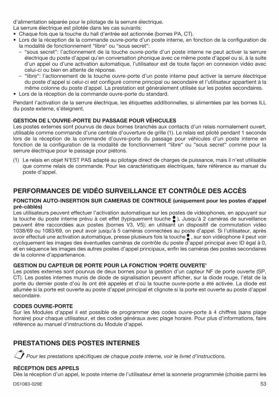
53DS1083-029E
d’alimentation séparée pour le pilotage de la serrure électrique.La serrure électrique est pilotée dans les cas suivants:
Chaque fois que la touche du hall d’entrée est actionnée (bornes PA, CT).Lors de la réception de la commande ouvre-porte d’un poste interne, en fonction de la confi guration de la modalité de fonctionnement “libre“ ou “sous secret“:
“sous secret“: l’actionnement de la touche ouvre-porte d’un poste interne ne peut activer la serrure électrique du poste d’appel qu’en conversation phonique avec ce même poste d’appel ou si, à la suite d’un appel ou d’une activation automatique, l’utilisateur est de toute façon en connexion vidéo avec celui-ci ou bien en attente de réponse.“libre“: l’actionnement de la touche ouvre-porte d’un poste interne peut activer la serrure électrique du poste d’appel si celui-ci est confi guré comme principal ou secondaire et l’utilisateur appartient à la même colonne du poste d’appel. La prestation est généralement utilisée sur les postes secondaires.
Lors de la réception de la commande ouvre-porte du standard.
Pendant l’activation de la serrure électrique, les étiquettes additionnelles, si alimentées par les bornes ILL du poste externe, s’éteignent.
GESTION DE L’OUVRE-PORTE DU PASSAGE POUR VÉHICULESLes postes externes sont pourvus de deux bornes branchés aux contacts d’un relais normalement ouvert, utilisable comme commande d’une centrale d’ouverture de grille (1). Le relais est piloté pendant 1 seconde lors de la réception de la commande d’ouvre-porte du passage pour véhicules d’un poste interne en fonction de la confi guration de la modalité de fonctionnement “libre“ ou “sous secret“ comme pour la serrure électrique pour le passage pour piétons.
(1) Le relais en objet N’EST PAS adapté au pilotage direct de charges de puissance, mais il n’est utilisable que comme relais de commande. Pour les caractéristiques électriques, faire référence au manuel du poste d’appel.
PERFORMANCES DE VIDÉO SURVEILLANCE ET CONTRÔLE DES ACCÈSFONCTION AUTO-INSERTION SUR CAMERAS DE CONTROLE (uniquement pour les postes d’appel pré-câblés)Les utilisateurs peuvent effectuer l’activation automatique sur les postes de vidéophones, en appuyant sur la touche du poste interne prévu à cet effet (typiquement touche ). Jusqu’à 2 caméras de surveillance peuvent être raccordées aux postes (bornes V3, V5); en utilisant un dispositif de commutation vidéo 1038/69 ou 1083/69, on peut avoir jusqu’à 5 caméras connectées au poste d’appel. Si l’utilisateur, après avoir effectué une activation automatique, presse plusieurs fois la touche , sur son vidéophone il peut voir cycliquement les images des éventuelles caméras de contrôle du poste d’appel principal avec ID égal à 0, et en séquence les images des autres postes d’appel principaux, enfi n les caméras des postes secondaires de la colonne d’appartenance.
GESTION DU CAPTEUR DE PORTE POUR LA FONCTION ‘PORTE OUVERTE’Les postes externes sont pourvus de deux bornes pour la gestion d’un capteur NF de porte ouverte (SP, CT). Les postes internes munis de diode de signalisation peuvent affi cher, sur la diode rouge, l’état de la porte du dernier poste d’où ils ont été appelés et d’où la touche ouvre-porte a été activée. La diode est allumée si la porte est ouverte au poste d’appel principal et clignote si la porte est ouverte au poste d’appel secondaire.
CODES OUVRE-PORTESur les Modules d’appel il est possible de programmer des codes ouvre-porte à 4 chiffres (sans plage horaire) pour chaque utilisateur, et des codes généraux avec plage horaire. Pour plus d’informations, faire référence au manuel d’instructions du Module d’appel.
PRESTATIONS DES POSTES INTERNES
Pour les prestations spécifi ques de chaque poste interne, voir le livret d’instructions.
RÉCEPTION DES APPELSDès la réception d’un appel, le poste interne de l’utilisateur émet la sonnerie programmée (choisie parmi les
••
–
–
•
§
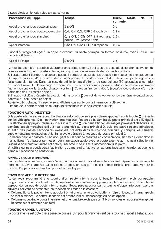
54 DS1083-029E
5 possibles), en fonction des temps suivants:
Provenance de l’appel Temps Durée totale de la sonnerie
Appel provenant du poste principal 3 s ON 3 s
Appel provenant du poste secondaire 0,4s ON, 0,2s OFF à 5 reprises 2,8 s
Appel provenant du standard 0,1s ON, 0,05s OFF à 3 reprises, pause 0,2s, répété 5 fois
2,8 s
Appel intercom 0,5s ON, 0,5s OFF, à 3 reprises 2,5 s
L’appel à l’étage est égal à un appel provenant du poste principal en termes de durée, mais il utilise une mélodie différente:
Appel à l’étage 3 s ON 3 s
Après réception d’un appel de vidéophone ou d’interphone, il est toujours possible de piloter l’activation de la serrure électrique du poste externe, sans qu’il soit nécessaire de décrocher le combiné.Si l’appartement comporte plusieurs postes internes en parallèle, les postes internes sonnent en séquence. Si l’appel provient d’un poste externe vidéophone, le poste interne 0 de l’utilisateur pilote également l’allumage de l’écran. Dans ce cas, durant le temps d’attente de décrochage (60 secondes à compter de l’appel avant le décrochage du combiné), les autres internes peuvent allumer leur écran à travers l’actionnement de la touche d’auto-insertion (fonction ‘renvoi vidéo’), jusqu’au décrochage d’un des combinés de l’utilisateur appelé.Si l’image est déjà présente, la pression de la touche permet de sélectionner les caméras éventuelles decontrôle du seul poste appelant. Après le décrochage, l’image ne sera affi chée que sur le poste interne qui a décroché.L’image de la caméra sera donc toujours présente sur un seul écran à la fois.
FONCTION AUTO-INSERTIONSi le poste interne est au repos, l’activation automatique sera possible en appuyant sur la touche présente sur les vidéophones. Dès l’activation automatique, l’écran de la caméra du poste principal avec ID égal à 0 s’affi che; en appuyant plusieurs fois sur la touche , on peut affi cher les images provenant de toutes les caméras supplémentaires (s’il y a lieu) branchées au poste principal 0, puis des autres postes principaux et enfi n des postes secondaires éventuels présents dans la colonne, toujours y compris les caméras supplémentaires éventuelles. À la fi n, le cycle démarre à nouveau du poste principal 0. En décrochant le combiné ou en appuyant sur la touche d’entrée en conversation, en cas de vidéophones mains libres, l’utilisateur se met en communication audio avec le poste externe au moment sélectionné. Quand la conversation audio est active, l’utilisateur peut à tout moment ouvrir la porte. Si l’utilisateur ne procède pas à l’activation du canal audio, l’activation automatique termine automatiquement après 60 secondes de l’activation.
APPEL VERS LE STANDARDLes postes internes sont munis d’une touche dédiée à l’appel vers le standard. Après avoir soulevé le combiné ou avoir appuyé sur la touche phonie, en cas de postes internes mains libres, appuyer sur la touche d’appel vers le standard pour effectuer l’appel.
ENVOI DES APPELS INTERCOMAprès avoir programmé une touche d’un poste interne pour la fonction intercom (voir paragraphe programmation), activer l’audio en décrochant le combiné ou en appuyant sur la touche d’activation phonie appropriée, en cas de poste interne mains libres, puis appuyer sur la touche d’appel intercom. Les cas suivants peuvent se présenter, en fonction de l’état de la colonne:
Colonne libre: le poste interne appelant émet une tonalité de validation (1 bip) et le poste interne appelé se met à sonner. La communication est établie lors du décrochage du poste appelé.Colonne occupée: le poste interne émet une tonalité de dissuasion (4 bips sonores en succession rapide). Raccrocher et retenter plus tard.
FONCTION APPEL A L’ETAGELe poste interne est doté d’une paire de bornes (CP) pour le branchement de la touche d’appel à l’étage. Lors
•
•
55DS1083-029E
de l’actionnement de la touche, le poste interne émet la sonnerie programmée durant 3 secondes (différente de celle pour les autres appels). Si l’utilisateur comporte plusieurs postes internes en parallèle, brancher cette touche uniquement sur le poste interne. Les postes internes sonneront en séquence.
SONNERIE SUPPLEMENTAIRELes postes internes sont munis d’une paire de bornes (S+, S-) pour le raccordement d’une sonnerie supplémentaire ou d’un relais ou même d’un répétiteur d’appel sans fi ls. Cette sonnerie est pilotée simultanément à l’émission d’une quelconque tonalité d’appel.
FONCTION PORTE OUVERTESi sur les postes d’appel un capteur de porte est branché aux bornes SP et CT, les postes internes peuvent tenir sous contrôle l’état physique des portes. Lorsque la porte d’un poste d’appel principal est ouverte la diode rouge est allumée, alors que si la porte d’un poste d’appel secondaire est ouverte la diode clignote. La performance n’est active que sur le dernier interphone ou vidéophone appelé où la touche ouvre-porte et son dernier poste externe correspondant appelant ont été activés.
FONCTIONS ADDITIONNELLESALLUMAGE DE L’ÉCLAIRAGE D’ESCALIERIl est possible de programmer une touche d’un poste interne pour l’activation du service d’éclairage d’escalier, au moyen d’un code spécial.
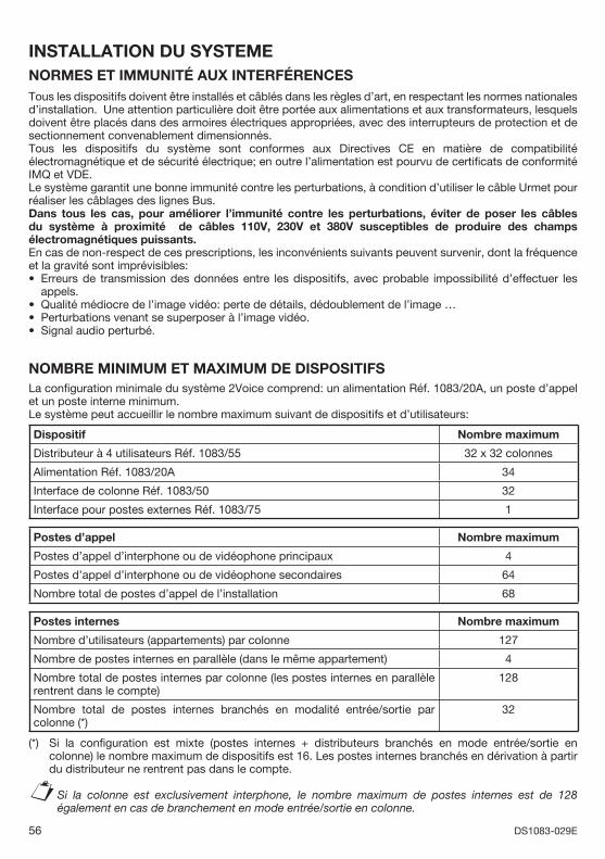
56 DS1083-029E
INSTALLATION DU SYSTEMENORMES ET IMMUNITÉ AUX INTERFÉRENCESTous les dispositifs doivent être installés et câblés dans les règles d’art, en respectant les normes nationales d’installation. Une attention particulière doit être portée aux alimentations et aux transformateurs, lesquels doivent être placés dans des armoires électriques appropriées, avec des interrupteurs de protection et de sectionnement convenablement dimensionnés.Tous les dispositifs du système sont conformes aux Directives CE en matière de compatibilité électromagnétique et de sécurité électrique; en outre l’alimentation est pourvu de certifi cats de conformité IMQ et VDE.Le système garantit une bonne immunité contre les perturbations, à condition d’utiliser le câble Urmet pour réaliser les câblages des lignes Bus.Dans tous les cas, pour améliorer l’immunité contre les perturbations, éviter de poser les câbles du système à proximité de câbles 110V, 230V et 380V susceptibles de produire des champs électromagnétiques puissants.En cas de non-respect de ces prescriptions, les inconvénients suivants peuvent survenir, dont la fréquence et la gravité sont imprévisibles:
Erreurs de transmission des données entre les dispositifs, avec probable impossibilité d’effectuer les appels.Qualité médiocre de l’image vidéo: perte de détails, dédoublement de l’image …Perturbations venant se superposer à l’image vidéo.Signal audio perturbé.
NOMBRE MINIMUM ET MAXIMUM DE DISPOSITIFSLa confi guration minimale du système 2Voice comprend: un alimentation Réf. 1083/20A, un poste d’appel et un poste interne minimum.Le système peut accueillir le nombre maximum suivant de dispositifs et d’utilisateurs:
Dispositif Nombre maximum
Distributeur à 4 utilisateurs Réf. 1083/55 32 x 32 colonnes
Alimentation Réf. 1083/20A 34
Interface de colonne Réf. 1083/50 32
Interface pour postes externes Réf. 1083/75 1
Postes d’appel Nombre maximum
Postes d’appel d’interphone ou de vidéophone principaux 4
Postes d’appel d’interphone ou de vidéophone secondaires 64
Nombre total de postes d’appel de l’installation 68
Postes internes Nombre maximum
Nombre d’utilisateurs (appartements) par colonne 127
Nombre de postes internes en parallèle (dans le même appartement) 4
Nombre total de postes internes par colonne (les postes internes en parallèle rentrent dans le compte)
128
Nombre total de postes internes branchés en modalité entrée/sortie par colonne (*)
32
(*) Si la confi guration est mixte (postes internes + distributeurs branchés en mode entrée/sortie en colonne) le nombre maximum de dispositifs est 16. Les postes internes branchés en dérivation à partir du distributeur ne rentrent pas dans le compte.
Si la colonne est exclusivement interphone, le nombre maximum de postes internes est de 128 également en cas de branchement en mode entrée/sortie en colonne.
•
•••
§
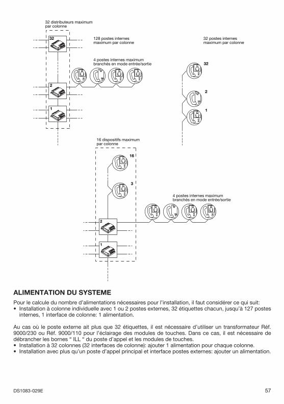
57DS1083-029E
1
2
32 128 postes internesmaximum par colonne
4 postes internes maximumbranchés en mode entrée/sortie 32
2
1
32 postes internesmaximum par colonne
32 distributeurs maximumpar colonne
2
1
3
16
16 dispositifs maximumpar colonne
4 postes internes maximumbranchés en mode entrée/sortie
ALIMENTATION DU SYSTEMEPour le calcule du nombre d’alimentations nécessaires pour l’installation, il faut considérer ce qui suit:
Installation à colonne individuelle avec 1 ou 2 postes externes, 32 étiquettes chacun, jusqu’à 127 postes internes, 1 interface de colonne: 1 alimentation.
Au cas où le poste externe ait plus que 32 étiquettes, il est nécessaire d’utiliser un transformateur Réf. 9000/230 ou Réf. 9000/110 pour l’éclairage des modules de touches. Dans ce cas, il est nécessaire de débrancher les bornes “ ILL “ du poste d’appel et les modules de touches.
Installation à 32 colonnes (32 interfaces de colonne): ajouter 1 alimentation pour chaque colonne.Installation avec plus qu’un poste d’appel principal et interface postes externes: ajouter un alimentation.
•
••
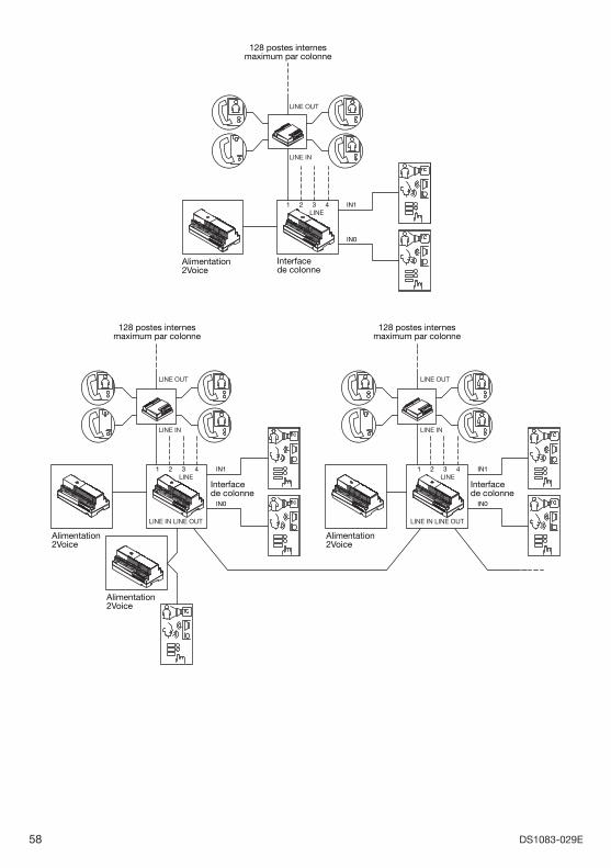
58 DS1083-029E
128 postes internesmaximum par colonne
LINE321 4 IN1
IN0
LINE OUT
LINE IN
Alimentation2Voice
Interfacede colonne
128 postes internesmaximum par colonne
128 postes internesmaximum par colonne
LINE IN LINE OUT
TC
TC
LINE321 4 IN1
IN0
LINE OUT
LINE IN
LINE IN LINE OUT
LINE321 4 IN1
IN0
LINE OUT
LINE IN
Alimentation2Voice
Alimentation2Voice
Alimentation2Voice
Interfacede colonne
Interfacede colonne
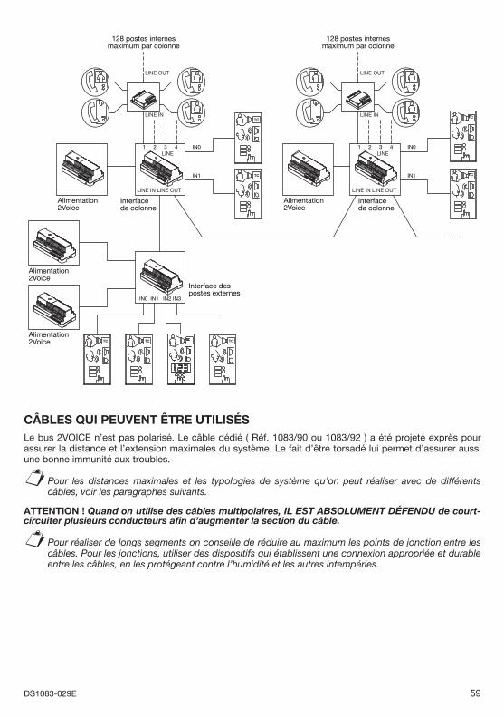
59DS1083-029E
128 postes internesmaximum par colonne
Interface despostes externes
128 postes internesmaximum par colonne
TCTC TC
TC
TC
TC
TC
LINE IN LINE OUT
LINE321 4 IN0
IN1
IN1 IN3IN2IN0
LINE OUT
LINE IN
LINE IN LINE OUT
LINE321 4 IN0
IN1
LINE OUT
LINE IN
TCAlimentation2Voice
Alimentation2Voice
Alimentation2Voice
Alimentation2Voice
Interfacede colonne
Interfacede colonne
CÂBLES QUI PEUVENT ÊTRE UTILISÉSLe bus 2VOICE n’est pas polarisé. Le câble dédié ( Réf. 1083/90 ou 1083/92 ) a été projeté exprès pour assurer la distance et l’extension maximales du système. Le fait d’être torsadé lui permet d’assurer aussi une bonne immunité aux troubles.
Pour les distances maximales et les typologies de système qu’on peut réaliser avec de différents câbles, voir les paragraphes suivants.
ATTENTION ! Quand on utilise des câbles multipolaires, IL EST ABSOLUMENT DÉFENDU de court-circuiter plusieurs conducteurs afi n d’augmenter la section du câble.
Pour réaliser de longs segments on conseille de réduire au maximum les points de jonction entre les câbles. Pour les jonctions, utiliser des dispositifs qui établissent une connexion appropriée et durable entre les câbles, en les protégeant contre l’humidité et les autres intempéries.
§
§
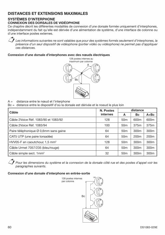
60 DS1083-029E
DISTANCES ET EXTENSIONS MAXIMALESSYSTÈMES D’INTERPHONECONNEXION DES DORSALES DE VIDÉOPHONE Ce chapitre décrit les différentes modalités de connexion d’une dorsale formée uniquement d’interphones, indépendamment du fait qu’elle est dérivée d’une alimentation de système, d’une interface de colonne ou d’une interface postes externes.
Les informations suivantes ne sont valables que pour des systèmes formés seulement d’interphones, la présence d’un seul dispositif de vidéophone (portier vidéo ou vidéophone) ne permet pas d’appliquer ces distances.
Connexion d’une dorsale d’interphones avec des nœuds électriques128 postes internes au maximum par colonne
Bc
A
A = distance entre le nœud et l’interphone Bc = distance entre le dispositif d’où la dorsale est dérivée et le noeud le plus loin
Câble N. Postes internes
distanceA Bc A+Bc
Câble 2Voice Réf. 1083/90 et 1083/92 128 50m 600m 600m
Câble 2Voice Réf. 1083/94 100 50m 375m 375m
Paire téléphonique Ø 0,6mm sans gaine 64 50m 300m 300m
CAT5 UTP (une paire torsadée) 64 50m 200m 200m
HVV05-F en caoutchouc 1,5 mm2 128 50m 300m 300m
Câble Urmet 7057/235 (bleu/rouge) 64 50m 300m 300m
Câble simple sect. 1mm2 32 50m 300m 300m
Pour les dimensions du système et la connexion de la dorsale côté rue et des postes d’appel voir les paragraphes suivants.
Connexion d’une dorsale d’interphone en entrée-sortie128
2
1Bc
128 postes internes par colonne
§
§
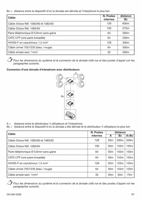
61DS1083-029E
Bc = distance entre le dispositif d’où la dorsale est dérivée et l’interphone le plus loin
Câble N. Postes internes
distanceBc
Câble 2Voice Réf. 1083/90 et 1083/92 128 600m
Câble 2Voice Réf. 1083/94 100 375m
Paire téléphonique Ø 0,6mm sans gaine 64 300m
CAT5 UTP (une paire torsadée) 64 200m
HVV05-F en caoutchouc 1,5 mm2 128 300m
Câble Urmet 7057/235 (bleu / rouge) 64 300m
Câble simple sect. 1mm2 32 300m
Pour les dimensions du système et la connexion de la dorsale côté rue et des postes d’appel voir les paragraphes suivants.
Connexion d’une dorsale d’interphone avec distributeurs
32
2
1
Bc
A
A = distance entre le distributeur 4 utilisateurs et l’interphone Bc = distance entre le dispositif d’où la dorsale a été dérivée et le distributeur 4 utilisateurs le plus loin
Câble N. Postes internes
distanceA Bc A+Bc
Câble 2Voice Réf. 1083/90 et 1083/92 128 50m 200m 200m
Câble 2Voice Réf. 1083/94 100 50m 125m 125m
Paire téléphonique Ø 0,6mm sans gaine 64 50m 150m 150m
CAT5 UTP (une paire torsadée) 64 50m 125m 125m
HVV05-F en caoutchouc 1,5 mm2 128 50m 125m 125m
Câble Urmet 7057/235 (bleu / rouge) 64 50m 125m 125m
Câble simple sect. 1mm2 32 50m 50m 75m
Pour les dimensions du système et la connexion de la dorsale côté rue et des postes d’appel voir les paragraphes suivants.
§
§
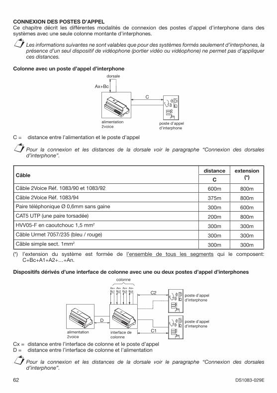
62 DS1083-029E
CONNEXION DES POSTES D’APPELCe chapitre décrit les différentes modalités de connexion des postes d’appel d’interphone dans des systèmes avec une seule colonne montante d’interphones.
Les informations suivantes ne sont valables que pour des systèmes formés seulement d’interphones, la présence d’un seul dispositif de vidéophone (portier vidéo ou vidéophone) ne permet pas d’appliquer ces distances.
Colonne avec un poste d’appel d’interphone
Ax+Bc
C
dorsale
poste d’appel d’interphone
alimentation2voice
C = distance entre l’alimentation et le poste d’appel
Pour la connexion et les distances de la dorsale voir le paragraphe “Connexion des dorsales d’interphone”.
Câbledistance extension
(*)C
Câble 2Voice Réf. 1083/90 et 1083/92 600m 800m
Câble 2Voice Réf. 1083/94 375m 800m
Paire téléphonique Ø 0,6mm sans gaine 300m 600m
CAT5 UTP (une paire torsadée) 200m 800m
HVV05-F en caoutchouc 1,5 mm2 300m 300m
Câble Urmet 7057/235 (bleu / rouge) 300m 300m
Câble simple sect. 1mm2 300m 300m
(*) l’extension du système est formée de l’ensemble de tous les segments qui le composent: C+Bc+A1+A2+…+An.
Dispositifs dérivés d’une interface de colonne avec une ou deux postes d’appel d’interphonescolonne
Ax+Bc4
Ax+Bc3
Ax+Bc2
D
Ax+Bc1 C2
C1alimentation2voice
interface de colonne
poste d’appel d’interphone
poste d’appel d’interphone
Cx = distance entre l’interface de colonne et le poste d’appel D = distance entre l’interface de colonne et l’alimentation
Pour la connexion et les distances de la dorsale voir le paragraphe “Connexion des dorsales d’interphone”.
§
§
§
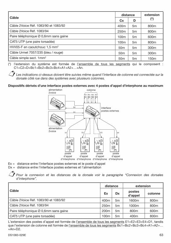
63DS1083-029E
Câbledistance extension
(*)Cx D
Câble 2Voice Réf. 1083/90 et 1083/92 400m 5m 800m
Câble 2Voice Réf. 1083/94 250m 5m 800mPaire téléphonique Ø 0,6mm sans gaine 100m 5m 600mCAT5 UTP (une paire torsadée) 100m 5m 800mHVV05-F en caoutchouc 1,5 mm2 50m 5m 300mCâble Urmet 7057/235 (bleu / rouge) 50m 5m 300mCâble simple sect. 1mm2 50m 5m 150m
(*) l’extension du système est formée de l’ensemble de tous les segments qui le composent : C1+C2+D+Bc1+Bc2+Bc3+Bc4+A1+A2+…+An.
Les indications ci-dessus doivent être suivies même quand l’interface de colonne est connectée sur la dorsale côté rue dans des systèmes avec plusieurs colonnes.
Dispositifs dérivés d’une interface postes externes avec 4 postes d’appel d’interphone au maximum
D1
D2
E4E3E2E1
Ax+Bc1
Ax+Bc2
Ax+Bc3
Ax+Bc4
colonne
interfacepostes externes
alimentation2voice
alimentation2voice
posted’appel
d’interphone
posted’appel
d’interphone
posted’appel
d’interphone
posted’appel
d’interphone
Ex = distance entre l’interface postes externes et le poste d’appel Dx = distance entre l’interface postes externes et l’alimentation
Pour la connexion et les distances de la dorsale voir le paragraphe “Connexion des dorsales d’interphone”.
Câbledistance extension
Ex Dxpostes d’appel
colonne
Câble 2Voice Réf. 1083/90 et 1083/92 400m 5m 1600m 800m
Câble 2Voice Réf. 1083/94 250m 5m 1000m 800m
Paire téléphonique Ø 0,6mm sans gaine 200m 5m 800m 600m
CAT5 UTP (une paire torsadée) 100m 5m 400m 800m
L’extension des postes d’appel est formée de l’ensemble de tous les segments E1+E2+E3+E4+D1, tandis que l’extension de colonne est formée de l’ensemble de tous les segments Bc1+Bc2+Bc3+Bc4+A1+A2+… +An+D2.
§
§
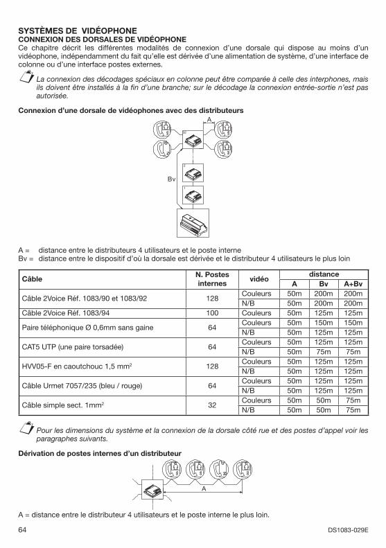
64 DS1083-029E
SYSTÈMES DE VIDÉOPHONECONNEXION DES DORSALES DE VIDÉOPHONE Ce chapitre décrit les différentes modalités de connexion d’une dorsale qui dispose au moins d’un vidéophone, indépendamment du fait qu’elle est dérivée d’une alimentation de système, d’une interface de colonne ou d’une interface postes externes.
La connexion des décodages spéciaux en colonne peut être comparée à celle des interphones, mais ils doivent être installés à la fi n d’une branche; sur le décodage la connexion entrée-sortie n’est pas autorisée.
Connexion d’une dorsale de vidéophones avec des distributeursA
Bv1
2
32
A = distance entre le distributeurs 4 utilisateurs et le poste interne Bv = distance entre le dispositif d’où la dorsale est dérivée et le distributeur 4 utilisateurs le plus loin
CâbleN. Postes internes
vidéodistance
A Bv A+Bv
Câble 2Voice Réf. 1083/90 et 1083/92 128Couleurs 50m 200m 200mN/B 50m 200m 200m
Câble 2Voice Réf. 1083/94 100 Couleurs 50m 125m 125m
Paire téléphonique Ø 0,6mm sans gaine 64Couleurs 50m 150m 150mN/B 50m 125m 125m
CAT5 UTP (une paire torsadée) 64Couleurs 50m 125m 125mN/B 50m 75m 75m
HVV05-F en caoutchouc 1,5 mm2 128Couleurs 50m 125m 125mN/B 50m 125m 125m
Câble Urmet 7057/235 (bleu / rouge) 64Couleurs 50m 125m 125mN/B 50m 125m 125m
Câble simple sect. 1mm2 32Couleurs 50m 50m 75mN/B 50m 50m 75m
Pour les dimensions du système et la connexion de la dorsale côté rue et des postes d’appel voir les paragraphes suivants.
Dérivation de postes internes d’un distributeur
A
A = distance entre le distributeur 4 utilisateurs et le poste interne le plus loin.
§
§
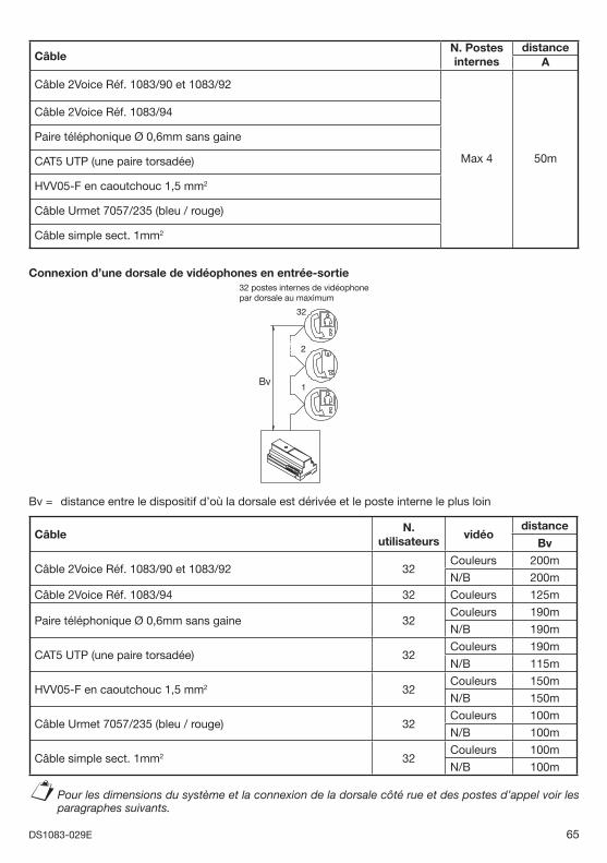
65DS1083-029E
CâbleN. Postes internes
distanceA
Câble 2Voice Réf. 1083/90 et 1083/92
Max 4 50m
Câble 2Voice Réf. 1083/94
Paire téléphonique Ø 0,6mm sans gaine
CAT5 UTP (une paire torsadée)
HVV05-F en caoutchouc 1,5 mm2
Câble Urmet 7057/235 (bleu / rouge)
Câble simple sect. 1mm2
Connexion d’une dorsale de vidéophones en entrée-sortie32 postes internes de vidéophonepar dorsale au maximum
Bv1
2
32
Bv = distance entre le dispositif d’où la dorsale est dérivée et le poste interne le plus loin
CâbleN.
utilisateursvidéo
distance
Bv
Câble 2Voice Réf. 1083/90 et 1083/92 32Couleurs 200m
N/B 200m
Câble 2Voice Réf. 1083/94 32 Couleurs 125m
Paire téléphonique Ø 0,6mm sans gaine 32Couleurs 190m
N/B 190m
CAT5 UTP (une paire torsadée) 32Couleurs 190m
N/B 115m
HVV05-F en caoutchouc 1,5 mm2 32Couleurs 150m
N/B 150m
Câble Urmet 7057/235 (bleu / rouge) 32Couleurs 100m
N/B 100m
Câble simple sect. 1mm2 32Couleurs 100m
N/B 100m
Pour les dimensions du système et la connexion de la dorsale côté rue et des postes d’appel voir les paragraphes suivants.
§
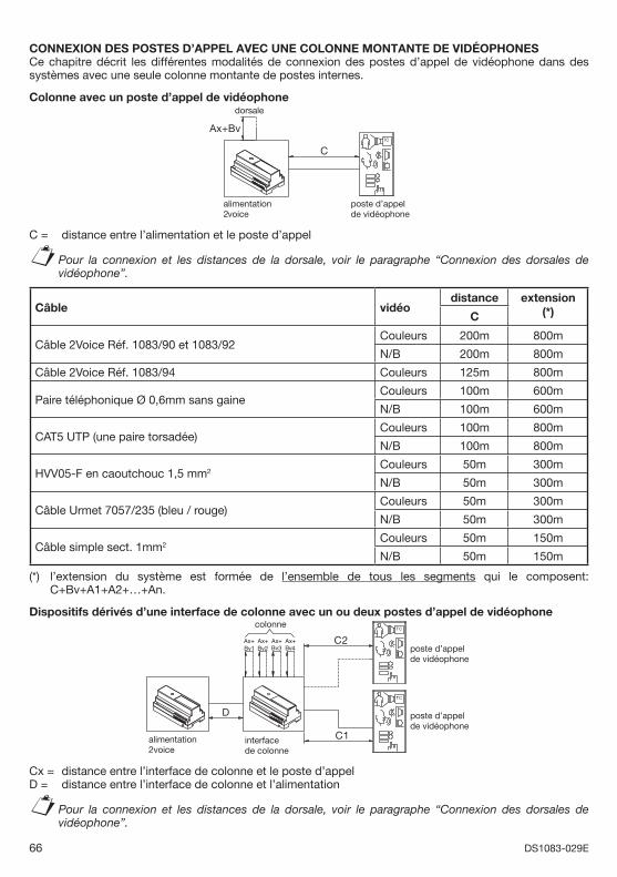
66 DS1083-029E
CONNEXION DES POSTES D’APPEL AVEC UNE COLONNE MONTANTE DE VIDÉOPHONESCe chapitre décrit les différentes modalités de connexion des postes d’appel de vidéophone dans des systèmes avec une seule colonne montante de postes internes.
Colonne avec un poste d’appel de vidéophone
alimentation2voice
TC
poste d’appel de vidéophone
dorsale
C
Ax+Bv
C = distance entre l’alimentation et le poste d’appel
Pour la connexion et les distances de la dorsale, voir le paragraphe “Connexion des dorsales de vidéophone”.
Câble vidéodistance extension
(*)C
Câble 2Voice Réf. 1083/90 et 1083/92Couleurs 200m 800m
N/B 200m 800m
Câble 2Voice Réf. 1083/94 Couleurs 125m 800m
Paire téléphonique Ø 0,6mm sans gaineCouleurs 100m 600m
N/B 100m 600m
CAT5 UTP (une paire torsadée)Couleurs 100m 800m
N/B 100m 800m
HVV05-F en caoutchouc 1,5 mm2Couleurs 50m 300m
N/B 50m 300m
Câble Urmet 7057/235 (bleu / rouge)Couleurs 50m 300m
N/B 50m 300m
Câble simple sect. 1mm2Couleurs 50m 150m
N/B 50m 150m
(*) l’extension du système est formée de l’ensemble de tous les segments qui le composent: C+Bv+A1+A2+…+An.
Dispositifs dérivés d’une interface de colonne avec un ou deux postes d’appel de vidéophone TC
interfacede colonne
alimentation2voice
TC
poste d’appel de vidéophone
poste d’appel de vidéophone
C1
C2Ax+Bv1
D
Ax+Bv2
Ax+Bv3
Ax+Bv4
colonne
Cx = distance entre l’interface de colonne et le poste d’appel D = distance entre l’interface de colonne et l’alimentation
Pour la connexion et les distances de la dorsale, voir le paragraphe “Connexion des dorsales de vidéophone”.
§
§
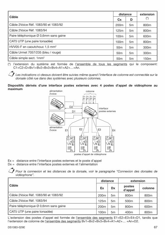
67DS1083-029E
Câbledistance extension
(*)Cx D
Câble 2Voice Réf. 1083/90 et 1083/92 200m 5m 800m
Câble 2Voice Réf. 1083/94 125m 5m 800m
Paire téléphonique Ø 0,6mm sans gaine 100m 5m 600m
CAT5 UTP (une paire torsadée) 100m 5m 800m
HVV05-F en caoutchouc 1,5 mm2 50m 5m 300m
Câble Urmet 7057/235 (bleu / rouge) 50m 5m 300m
Câble simple sect. 1mm2 50m 5m 150m
(*) l’extension du système est formée de l’ensemble de tous les segments qui le composent: C1+C2+D+Bv1+Bv2+Bv3+Bv4+A1+A2+…+An.
Les indications ci-dessus doivent être suivies même quand l’interface de colonne est connectée sur la dorsale côté rue dans des systèmes avec plusieurs colonnes.
Dispositifs dérivés d’une interface postes externes avec 4 postes d’appel de vidéophone au maximum
alimentation2voice
alimentation2voice
TC
interface postes externes
TC TC TC
colonne
Ax+Bv4
Ax+Bv3
Ax+Bv2
Ax+Bv1
E1 E2 E3 E4
D2
D1
postes d’appel de vidéophone
Ex = distance entre l’interface postes externes et le poste d’appel Dx = distance entre l’interface postes externes et l’alimentation
Pour la connexion et les distances de la dorsale, voir le paragraphe “Connexion des dorsales de vidéophone”.
Câbledistance extension
Ex Dxpostes d’appel
colonne
Câble 2Voice Réf. 1083/90 et 1083/92 200m 5m 800m 800m
Câble 2Voice Réf. 1083/94 125m 5m 500m 800m
Paire téléphonique Ø 0,6mm sans gaine 200m 5m 800m 600m
CAT5 UTP (une paire torsadée) 100m 5m 400m 800m
L’extension des postes d’appel est formée de l’ensemble des segments E1+E2+E3+E4+D1, tandis que l’extension de colonne de l’ensemble des segments Bv1+Bv2+Bv3+Bv4+A1+A2+… +An+D2.
§
§
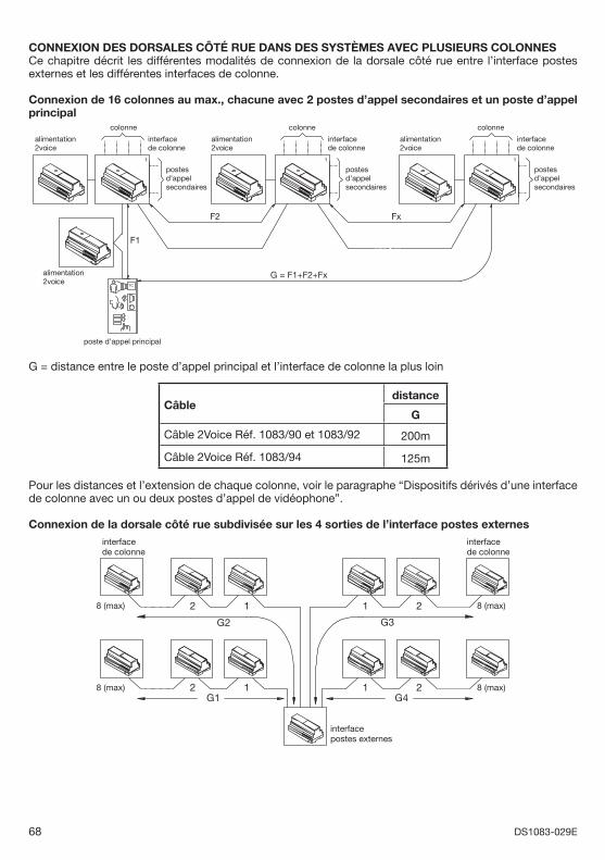
68 DS1083-029E
CONNEXION DES DORSALES CÔTÉ RUE DANS DES SYSTÈMES AVEC PLUSIEURS COLONNESCe chapitre décrit les différentes modalités de connexion de la dorsale côté rue entre l’interface postes externes et les différentes interfaces de colonne.
Connexion de 16 colonnes au max., chacune avec 2 postes d’appel secondaires et un poste d’appel principal
1
alimentation2voice
alimentation2voice
alimentation2voice
interfacede colonne
interfacede colonne
interfacede colonne
alimentation2voice
TC
postesd’appelsecondaires
postesd’appelsecondaires
postesd’appelsecondaires
F1
1
F2 Fx
G = F1+F2+Fx
poste d’appel principal
1
colonne colonne colonne
G = distance entre le poste d’appel principal et l’interface de colonne la plus loin
Câbledistance
G
Câble 2Voice Réf. 1083/90 et 1083/92 200m
Câble 2Voice Réf. 1083/94 125m
Pour les distances et l’extension de chaque colonne, voir le paragraphe “Dispositifs dérivés d’une interface de colonne avec un ou deux postes d’appel de vidéophone”.
Connexion de la dorsale côté rue subdivisée sur les 4 sorties de l’interface postes externes
1 2 8 (max)
2112
8 (max) 2 1
interfacede colonne
interfacede colonne
interfacepostes externes
8 (max)
G2
G1 G4
G3
8 (max)
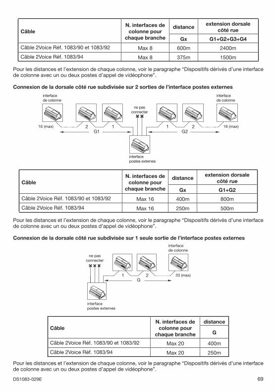
69DS1083-029E
CâbleN. interfaces de
colonne pour chaque branche
distanceextension dorsale
côté rue
Gx G1+G2+G3+G4
Câble 2Voice Réf. 1083/90 et 1083/92 Max 8 600m 2400m
Câble 2Voice Réf. 1083/94 Max 8 375m 1500m
Pour les distances et l’extension de chaque colonne, voir le paragraphe “Dispositifs dérivés d’une interface de colonne avec un ou deux postes d’appel de vidéophone”.
Connexion de la dorsale côté rue subdivisée sur 2 sorties de l’interface postes externes
16 (max)G2G1
16 (max) 2 1
interface de colonne
interface de colonne
ne pasconnecter
1 2
interface postes externes
CâbleN. interfaces de
colonne pour chaque branche
distanceextension dorsale
côté rue
Gx G1+G2
Câble 2Voice Réf. 1083/90 et 1083/92 Max 16 400m 800m
Câble 2Voice Réf. 1083/94 Max 16 250m 500m
Pour les distances et l’extension de chaque colonne, voir le paragraphe “Dispositifs dérivés d’une interface de colonne avec un ou deux postes d’appel de vidéophone”.
Connexion de la dorsale côté rue subdivisée sur 1 seule sortie de l’interface postes externes
G20 (max)
interfacepostes externes
21
ne pasconnecter
interfacede colonne
CâbleN. interfaces de
colonne pour chaque branche
distance
G
Câble 2Voice Réf. 1083/90 et 1083/92 Max 20 400m
Câble 2Voice Réf. 1083/94 Max 20 250m
Pour les distances et l’extension de chaque colonne, voir le paragraphe “Dispositifs dérivés d’une interface de colonne avec un ou deux postes d’appel de vidéophone”.
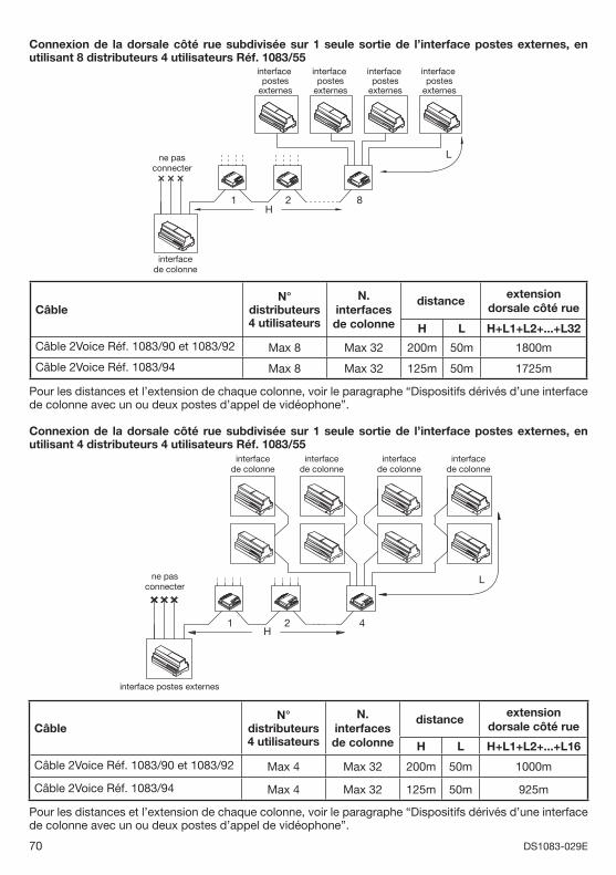
70 DS1083-029E
Connexion de la dorsale côté rue subdivisée sur 1 seule sortie de l’interface postes externes, en utilisant 8 distributeurs 4 utilisateurs Réf. 1083/55
interfacede colonne
ne pasconnecter
interfacepostes
externes
interfacepostes
externes
interfacepostes
externes
interfacepostes
externes
L
1 2 8H
CâbleN°
distributeurs 4 utilisateurs
N. interfaces de colonne
distanceextension
dorsale côté rue
H L H+L1+L2+...+L32
Câble 2Voice Réf. 1083/90 et 1083/92 Max 8 Max 32 200m 50m 1800m
Câble 2Voice Réf. 1083/94 Max 8 Max 32 125m 50m 1725m
Pour les distances et l’extension de chaque colonne, voir le paragraphe “Dispositifs dérivés d’une interface de colonne avec un ou deux postes d’appel de vidéophone”.
Connexion de la dorsale côté rue subdivisée sur 1 seule sortie de l’interface postes externes, en utilisant 4 distributeurs 4 utilisateurs Réf. 1083/55
interface postes externes
21
ne pasconnecter
L
H4
interfacede colonne
interfacede colonne
interfacede colonne
interfacede colonne
CâbleN°
distributeurs 4 utilisateurs
N. interfaces de colonne
distanceextension
dorsale côté rue
H L H+L1+L2+...+L16
Câble 2Voice Réf. 1083/90 et 1083/92 Max 4 Max 32 200m 50m 1000m
Câble 2Voice Réf. 1083/94 Max 4 Max 32 125m 50m 925m
Pour les distances et l’extension de chaque colonne, voir le paragraphe “Dispositifs dérivés d’une interface de colonne avec un ou deux postes d’appel de vidéophone”.
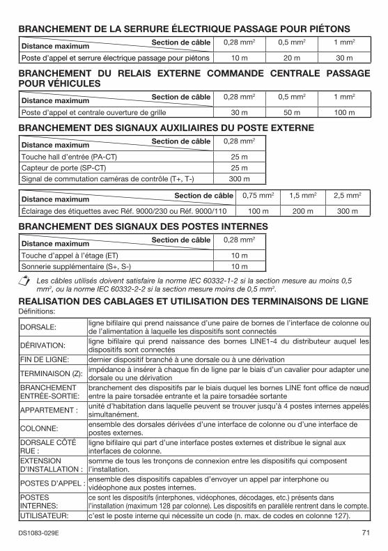
71DS1083-029E
BRANCHEMENT DE LA SERRURE ÉLECTRIQUE PASSAGE POUR PIÉTONS Section de câbleDistance maximum 0,28 mm2 0,5 mm2 1 mm2
Poste d’appel et serrure électrique passage pour piétons 10 m 20 m 30 m
BRANCHEMENT DU RELAIS EXTERNE COMMANDE CENTRALE PASSAGE POUR VÉHICULES
Section de câbleDistance maximum 0,28 mm2 0,5 mm2 1 mm2
Poste d’appel et centrale ouverture de grille 30 m 50 m 100 m
BRANCHEMENT DES SIGNAUX AUXILIAIRES DU POSTE EXTERNE Section de câbleDistance maximum 0,28 mm2
Touche hall d’entrée (PA-CT) 25 m
Capteur de porte (SP-CT) 25 m
Signal de commutation caméras de contrôle (T+, T-) 300 m
Section de câbleDistance maximum 0,75 mm2 1,5 mm2 2,5 mm2
Éclairage des étiquettes avec Réf. 9000/230 ou Réf. 9000/110 100 m 200 m 300 m
BRANCHEMENT DES SIGNAUX DES POSTES INTERNES Section de câbleDistance maximum 0,28 mm2
Touche d’appel à l’étage (ET) 10 m
Sonnerie supplémentaire (S+, S-) 10 m
Les câbles utilisés doivent satisfaire la norme IEC 60332-1-2 si la section mesure au moins 0,5 mm2, ou la norme IEC 60332-2-2 si la section mesure moins de 0,5 mm2.
REALISATION DES CABLAGES ET UTILISATION DES TERMINAISONS DE LIGNEDéfi nitions:
DORSALE: ligne bifi laire qui prend naissance d’une paire de bornes de l’interface de colonne ou de l’alimentation à laquelle les dispositifs sont connectés
DÉRIVATION: ligne bifi laire qui prend naissance des bornes LINE1-4 du distributeur auquel les dispositifs sont connectés
FIN DE LIGNE: dernier dispositif branché à une dorsale ou à une dérivation
TERMINAISON (Z): impédance à insérer à chaque fi n de ligne par le biais d’un cavalier pour adapter une dorsale ou une dérivation
BRANCHEMENT ENTRÉE-SORTIE:
branchement des dispositifs par le biais duquel les bornes LINE font offi ce de nœud entre la paire torsadée entrante et la paire torsadée sortante
APPARTEMENT : unité d’habitation dans laquelle peuvent se trouver jusqu’à 4 postes internes appelés simultanément.
COLONNE: ensemble des dorsales dérivées d’une interface de colonne ou d’une interface de postes externes.
DORSALE CÔTÉ RUE :
ligne bifi laire qui part d’une interface postes externes et distribue le signal aux interfaces de colonne.
EXTENSION D’INSTALLATION :
somme de tous les tronçons de connexion entre les dispositifs qui composent l’installation.
POSTES D’APPEL : ensemble des dispositifs capables d’envoyer un appel par interphone ou vidéophone aux postes internes.
POSTES INTERNES:
ce sont les dispositifs (interphones, vidéophones, décodages, etc.) présents dans l’installation (maximum 128 par colonne). Les dispositifs en parallèle rentrent dans le compte.
UTILISATEUR: c’est le poste interne qui nécessite un code (n. max. de codes en colonne 127).
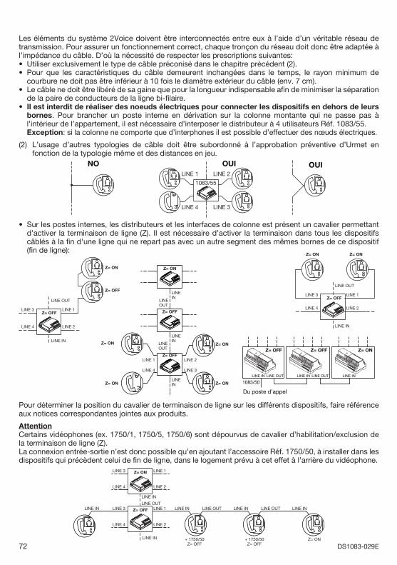
72 DS1083-029E
Les éléments du système 2Voice doivent être interconnectés entre eux à l’aide d’un véritable réseau de transmission. Pour assurer un fonctionnement correct, chaque tronçon du réseau doit donc être adaptée à l’impédance du câble. D’où la nécessité de respecter les prescriptions suivantes:
Utiliser exclusivement le type de câble préconisé dans le chapitre précédent (2).Pour que les caractéristiques du câble demeurent inchangées dans le temps, le rayon minimum de courbure ne doit pas être inférieur à 10 fois le diamètre extérieur du câble (env. 7 cm).Le câble ne doit être libéré de sa gaine que pour la longueur indispensable afi n de minimiser la séparation de la paire de conducteurs de la ligne bi-fi laire.Il est interdit de réaliser des noeuds électriques pour connecter les dispositifs en dehors de leurs bornes. Pour brancher un poste interne en dérivation sur la colonne montante qui ne passe pas à l’intérieur de l’appartement, il est nécessaire d’interposer le distributeur à 4 utilisateurs Réf. 1083/55.
Exception: si la colonne ne comporte que d’interphones il est possible d’effectuer des nœuds électriques.
(2) L’usage d’autres typologies de câble doit être subordonné à l’approbation préventive d’Urmet en fonction de la typologie même et des distances en jeu.
LINE 1
LINE 4
LINE 2
LINE 3
1083/55
NO OUIOUI
Sur les postes internes, les distributeurs et les interfaces de colonne est présent un cavalier permettant d’activer la terminaison de ligne (Z). Il est nécessaire d’activer la terminaison dans tous les dispositifs câblés à la fi n d’une ligne qui ne repart pas avec un autre segment des mêmes bornes de ce dispositif (fi n de ligne):
Z= ON
Z= OFF
LINE OUT
LINE IN
LINE 1LINE 3
LINE 4 LINE 2
Z= OFF
Z= ON
LINE 1LINE 3
LINE 4 LINE 2
Z= ON
LINE OUT
LINE IN
Z= OFFLINEOUT
LINEIN
LINEOUT
LINEIN
LINEIN
LINE 1
LINE 4
LINE 2
LINE 3
Z= ON
Z= OFF
Z= OFF
Z= ON
Z= ON
Z= ON
Z= ON
LINE IN
Z= OFF Z= ON
1083/50LINE OUT LINE INLINE IN
Z= OFF
LINE OUT
Du poste d’appel
Pour déterminer la position du cavalier de terminaison de ligne sur les différents dispositifs, faire référence aux notices correspondantes jointes aux produits.
AttentionCertains vidéophones (ex. 1750/1, 1750/5, 1750/6) sont dépourvus de cavalier d’habilitation/exclusion de la terminaison de ligne (Z).La connexion entrée-sortie n’est donc possible qu’en ajoutant l’accessoire Réf. 1750/50, à installer dans les dispositifs qui précèdent celui de fi n de ligne, dans le logement prévu à cet effet à l’arrière du vidéophone.
LINE IN
LINE OUT
LINE 1LINE 3
LINE 4 LINE 2
Z= ON
LINE IN
LINE 1 LINE INLINE IN LINE OUT
+ 1750/50Z= OFF
+ 1750/50Z= OFF
Z= ON
LINE 3
LINE 4 LINE 2
Z= OFF LINE IN LINE OUT LINE IN
••
•
•
•
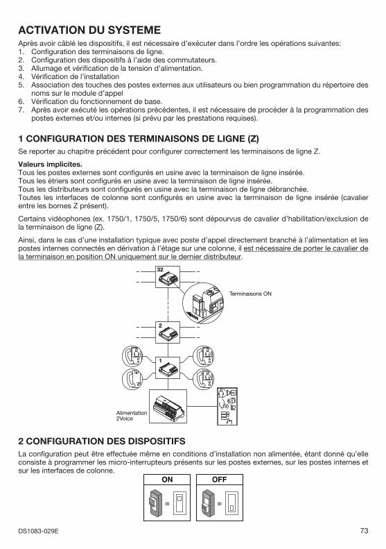
73DS1083-029E
ACTIVATION DU SYSTEMEAprès avoir câblé les dispositifs, il est nécessaire d’exécuter dans l’ordre les opérations suivantes:1. Confi guration des terminaisons de ligne.2. Confi guration des dispositifs à l’aide des commutateurs.3. Allumage et vérifi cation de la tension d’alimentation.4. Vérifi cation de l’installation5. Association des touches des postes externes aux utilisateurs ou bien programmation du répertoire des
noms sur le module d’appel6. Vérifi cation du fonctionnement de base.7. Après avoir exécuté les opérations précédentes, il est nécessaire de procéder à la programmation des
postes externes et/ou internes (si prévu par les prestations requises).
1 CONFIGURATION DES TERMINAISONS DE LIGNE (Z) Se reporter au chapitre précédent pour confi gurer correctement les terminaisons de ligne Z.
Valeurs implicites.Tous les postes externes sont confi gurés en usine avec la terminaison de ligne insérée.Tous les étriers sont confi gurés en usine avec la terminaison de ligne insérée.Tous les distributeurs sont confi gurés en usine avec la terminaison de ligne débranchée.Toutes les interfaces de colonne sont confi gurés en usine avec la terminaison de ligne insérée (cavalier entre les bornes Z présent).
Certains vidéophones (ex. 1750/1, 1750/5, 1750/6) sont dépourvus de cavalier d’habilitation/exclusion de la terminaison de ligne (Z).
Ainsi, dans le cas d’une installation typique avec poste d’appel directement branché à l’alimentation et les postes internes connectés en dérivation à l’étage sur une colonne, il est nécessaire de porter le cavalier de la terminaison en position ON uniquement sur le dernier distributeur.
Alimentation2Voice
TC
32
2
1
Terminaisons ON
2 CONFIGURATION DES DISPOSITIFS La confi guration peut être effectuée même en conditions d’installation non alimentée, étant donné qu’elle consiste à programmer les micro-interrupteurs présents sur les postes externes, sur les postes internes et sur les interfaces de colonne.
= =ONON
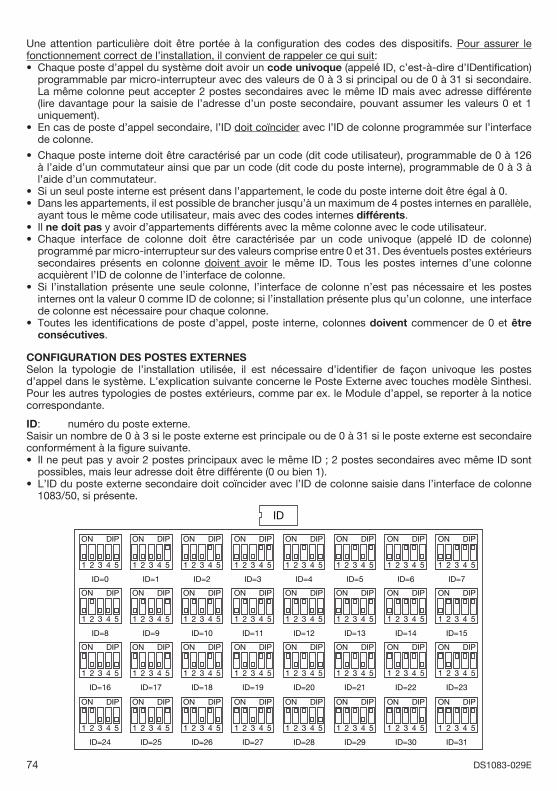
74 DS1083-029E
Une attention particulière doit être portée à la confi guration des codes des dispositifs. Pour assurer le fonctionnement correct de l’installation, il convient de rappeler ce qui suit:
Chaque poste d’appel du système doit avoir un code univoque (appelé ID, c’est-à-dire d’IDentifi cation) programmable par micro-interrupteur avec des valeurs de 0 à 3 si principal ou de 0 à 31 si secondaire. La même colonne peut accepter 2 postes secondaires avec le même ID mais avec adresse différente (lire davantage pour la saisie de l’adresse d’un poste secondaire, pouvant assumer les valeurs 0 et 1 uniquement).En cas de poste d’appel secondaire, l’ID doit coïncider avec l’ID de colonne programmée sur l’interface de colonne. Chaque poste interne doit être caractérisé par un code (dit code utilisateur), programmable de 0 à 126 à l’aide d’un commutateur ainsi que par un code (dit code du poste interne), programmable de 0 à 3 à l’aide d’un commutateur.Si un seul poste interne est présent dans l’appartement, le code du poste interne doit être égal à 0. Dans les appartements, il est possible de brancher jusqu’à un maximum de 4 postes internes en parallèle, ayant tous le même code utilisateur, mais avec des codes internes différents.Il ne doit pas y avoir d’appartements différents avec la même colonne avec le code utilisateur.Chaque interface de colonne doit être caractérisée par un code univoque (appelé ID de colonne) programmé par micro-interrupteur sur des valeurs comprise entre 0 et 31. Des éventuels postes extérieurs secondaires présents en colonne doivent avoir le même ID. Tous les postes internes d’une colonne acquièrent l’ID de colonne de l’interface de colonne.Si l’installation présente une seule colonne, l’interface de colonne n’est pas nécessaire et les postes internes ont la valeur 0 comme ID de colonne; si l’installation présente plus qu’un colonne, une interface de colonne est nécessaire pour chaque colonne.Toutes les identifi cations de poste d’appel, poste interne, colonnes doivent commencer de 0 et être consécutives.
CONFIGURATION DES POSTES EXTERNESSelon la typologie de l’installation utilisée, il est nécessaire d’identifi er de façon univoque les postes d’appel dans le système. L’explication suivante concerne le Poste Externe avec touches modèle Sinthesi.Pour les autres typologies de postes extérieurs, comme par ex. le Module d’appel, se reporter à la notice correspondante.
ID: numéro du poste externe.Saisir un nombre de 0 à 3 si le poste externe est principale ou de 0 à 31 si le poste externe est secondaire conformément à la fi gure suivante.
Il ne peut pas y avoir 2 postes principaux avec le même ID ; 2 postes secondaires avec même ID sont possibles, mais leur adresse doit être différente (0 ou bien 1). L’ID du poste externe secondaire doit coïncider avec l’ID de colonne saisie dans l’interface de colonne 1083/50, si présente.
ID
ON DIP
4321 5
ID=0
ON DIP
4321 5
ID=1
ON DIP
4321 5
ID=2
ON DIP
4321 5
ID=3
ON DIP
4321 5
ID=4
ON DIP
4321 5
ID=5
ON DIP
4321 5
ID=6
ON DIP
4321 5
ID=7
ON DIP
4321 5
ID=8
ON DIP
4321 5
ID=9
ON DIP
4321 5
ID=10
ON DIP
4321 5
ID=11
ON DIP
4321 5
ID=12
ON DIP
4321 5
ID=13
ON DIP
4321 5
ID=14
ON DIP
4321 5
ID=15
ON DIP
4321 5
ID=16
ON DIP
4321 5
ID=17
ON DIP
4321 5
ID=18
ON DIP
4321 5
ID=19
ON DIP
4321 5
ID=20
ON DIP
4321 5
ID=21
ON DIP
4321 5
ID=22
ON DIP
4321 5
ID=23
ON DIP
4321 5
ID=24
ON DIP
4321 5
ID=25
ON DIP
4321 5
ID=26
ON DIP
4321 5
ID=27
ON DIP
4321 5
ID=28
ON DIP
4321 5
ID=29
ON DIP
4321 5
ID=30
ON DIP
4321 5
ID=31
•
•
•
••
••
•
•
•
•
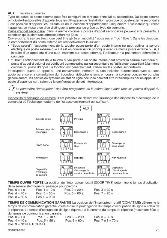
75DS1083-029E
AUX: saisies auxiliairesType de poste: le poste externe peut être confi guré en tant que principal ou secondaire. Du poste externe principale il est possible d’appeler tous les utilisateurs de l’installation, alors que du poste externe secondaire il est possible d’appeler les utilisateurs de la colonne d’appartenance uniquement. L’utilisateur qui reçoit l’appel est en mesure en d’en distinguer la provenance grâce au type de sonnerie.Poste d’appel secondaire: dans la même colonne 2 postes d’appel secondaires peuvent être présents, à condition qu’ils aient une adresse différente (0 ou 1).Ouvre-porte: la serrure électrique peut être gérée en modalité “ sous secret “ ou “ libre “. Dans les deux cas, le comportement du poste externe est respectivement le suivant:
“Sous secret”: l’actionnement de la touche ouvre-porte d’un poste interne ne peut activer la serrure électrique du poste externe que s’il est en conversation phonique avec ce même poste externe ou si, à la suite d’un appel (ou d’une auto-insertion sur poste externe), l’utilisateur n’a pas encore décroché le combiné.“Libre”: l’actionnement de la touche ouvre-porte d’un poste interne peut activer la serrure électrique du poste d’appel si celui-ci est confi guré comme principal ou secondaire et l’utilisateur appartient à la même colonne du poste d’appel. La fonction est généralement utilisée sur les postes secondaires.
Interruption: quand un appel ou une conversation intercom ou une inclusion automatique avec ou sans audio ou encore la consultation du répondeur vidéophone sont en cours, la colonne concernée ou, plus généralement, les parties de système en état de ligne occupée peuvent être interrompues par un appel d’un poste d’appel ou non, selon de la confi guration de cet interrupteur.
Le paramètre “interruption” doit être programmé de la même façon dans tous les postes d’appel du système.
Dispositifs d’éclairage de caméra: il est possible de désactiver l’allumage des dispositifs d’éclairage de la caméra là où l’éclairage nocturne de l’espace environnant est suffi sant.
AUX
ON DIP
4321 5
Principal
ON DIP
4321 5
Secondaire
ON DIP
4321 5
Secondaire 0
ON DIP
4321 5
Secondaire 1
ON DIP
4321 5
Ouvre-portelibre
ON DIP
4321 5
Ouvre-porte sous secret
ON DIP
4321 5
Habilitée
ON DIP
4321 5
Non habilitée
ON DIP
4321 5
Dispositifsd’éclairage de caméra désactivés
Type de poste
Adresse de poste secondaire
Ouvre-porte
Dispositifsd’éclairagede caméra
ON DIP
4321 5
Dispositifsd’éclairage de caméra activés
Interruption
TEMPS OUVRE-PORTE La position de l’interrupteur rotatif (DOOR TIME) détermine le temps d’activation de la serrure électrique du passage pour piétons.Pos. 0 = 1 s Pos. 1 = 10 s Pos. 2 = 20 s Pos. 3 = 30 sPos. 4 = 40 s Pos. 5 = 50 s Pos. 6 = 60 s Pos. 7 = 70 sPos. 8 = 80 s Pos. 9 = 90 s
TEMPS DE COMMUNICATION GARANTIE La position de l’interrupteur rotatif (CONV TIME) détermine le temps de communication garantie, c’est-à-dire la prolongation du temps d’occupation de ligne au-delà de la réponse. Le temps d’occupation de ligne équivaut à la somme du temps de réponse (maximum 60s) et du temps de communication garantie.Pos. 0 = 1 s Pos. 1 = 10 s Pos. 2 = 20 s Pos. 3 = 30 sPos. 4 = 40 s Pos. 5 = 50 s Pos. 6 = 60 s Pos. 7 e 8 = 70 sPos. 9 = NON AUTORISÉE
•
•
§
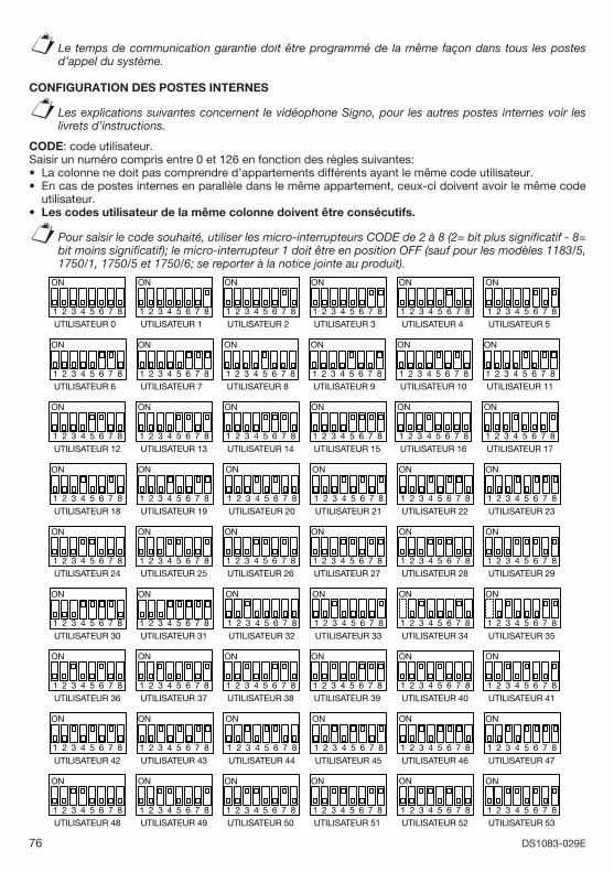
76 DS1083-029E
Le temps de communication garantie doit être programmé de la même façon dans tous les postes d’appel du système.
CONFIGURATION DES POSTES INTERNES
Les explications suivantes concernent le vidéophone Signo, pour les autres postes internes voir les livrets d’instructions.
CODE: code utilisateur.Saisir un numéro compris entre 0 et 126 en fonction des règles suivantes:
La colonne ne doit pas comprendre d’appartements différents ayant le même code utilisateur.En cas de postes internes en parallèle dans le même appartement, ceux-ci doivent avoir le même code utilisateur.Les codes utilisateur de la même colonne doivent être consécutifs.
Pour saisir le code souhaité, utiliser les micro-interrupteurs CODE de 2 à 8 (2= bit plus signifi catif - 8= bit moins signifi catif); le micro-interrupteur 1 doit être en position OFF (sauf pour les modèles 1183/5, 1750/1, 1750/5 et 1750/6; se reporter à la notice jointe au produit).
ON
UTILISATEUR 4
7654321 8
ON
UTILISATEUR 5
7654321 8
ON
UTILISATEUR 0
7654321 8
ON
UTILISATEUR 1
7654321 8
ON
UTILISATEUR 2
7654321 8
ON
UTILISATEUR 3
7654321 8
ON
UTILISATEUR 6
7654321 8
ON
UTILISATEUR 7
7654321 8
ON
UTILISATEUR 8
7654321 8
ON
UTILISATEUR 9
7654321 8
ON
UTILISATEUR 10
7654321 8
ON
UTILISATEUR 11
7654321 8
ON
UTILISATEUR 12
7654321 8
ON
UTILISATEUR 13
7654321 8
ON
UTILISATEUR 14
7654321 8
ON
UTILISATEUR 15
7654321 8
ON
UTILISATEUR 16
7654321 8
ON
UTILISATEUR 17
7654321 8
ON
UTILISATEUR 18
7654321 8
ON
UTILISATEUR 19
7654321 8
ON
UTILISATEUR 20
7654321 8
ON
UTILISATEUR 21
7654321 8
ON
UTILISATEUR 22
7654321 8
ON
UTILISATEUR 23
7654321 8
ON
UTILISATEUR 24
7654321 8
ON
UTILISATEUR 25
7654321 8
ON
UTILISATEUR 26
7654321 8
ON
UTILISATEUR 27
7654321 8
ON
UTILISATEUR 28
7654321 8
ON
UTILISATEUR 29
7654321 8
ON
UTILISATEUR 30
7654321 8
ON
UTILISATEUR 31
7654321 8
ON
UTILISATEUR 32
7654321 8
ON
UTILISATEUR 33
7654321 8
ON
UTILISATEUR 34
7654321 8
ON
UTILISATEUR 35
7654321 8
ON
UTILISATEUR 48
7654321 8
ON
UTILISATEUR 49
7654321 8
ON
UTILISATEUR 36
7654321 8
ON
UTILISATEUR 37
7654321 8
ON
UTILISATEUR 38
7654321 8
ON
UTILISATEUR 39
7654321 8
ON
UTILISATEUR 40
7654321 8
ON
UTILISATEUR 41
7654321 8
ON
UTILISATEUR 42
7654321 8
ON
UTILISATEUR 43
7654321 8
ON
UTILISATEUR 44
7654321 8
ON
UTILISATEUR 45
7654321 8
ON
UTILISATEUR 46
7654321 8
ON
UTILISATEUR 47
7654321 8
ON
UTILISATEUR 50
7654321 8
ON
UTILISATEUR 51
7654321 8
ON
UTILISATEUR 52
7654321 8
ON
UTILISATEUR 53
7654321 8
§
§
••
•
§
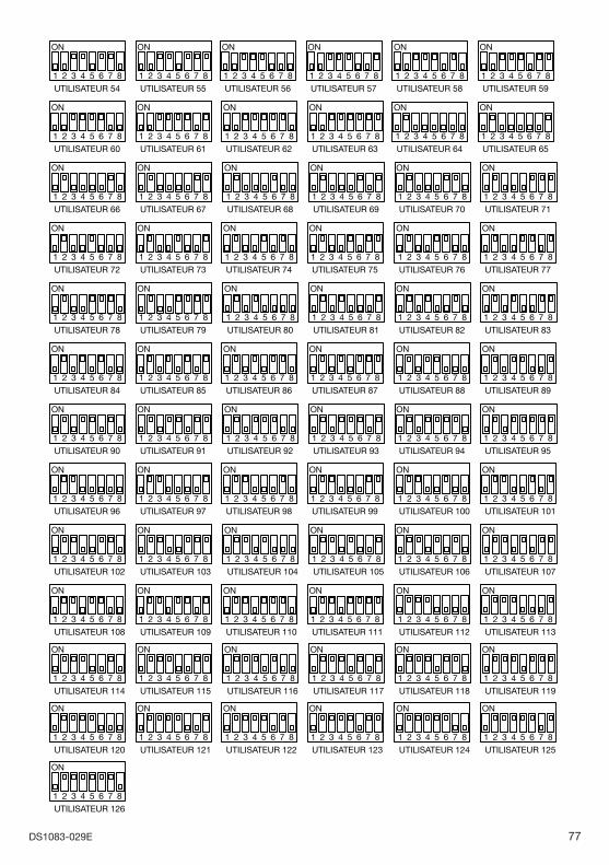
77DS1083-029E
ON
UTILISATEUR 84
7654321 8
ON
UTILISATEUR 85
7654321 8
ON
UTILISATEUR 86
7654321 8
ON
UTILISATEUR 87
7654321 8
ON
UTILISATEUR 102
7654321 8
ON
UTILISATEUR 103
7654321 8
ON
UTILISATEUR 108
7654321 8
ON
UTILISATEUR 109
7654321 8
ON
UTILISATEUR 110
7654321 8
ON
UTILISATEUR 111
7654321 8
ON
UTILISATEUR 114
7654321 8
ON
UTILISATEUR 115
7654321 8
ON
UTILISATEUR 116
7654321 8
ON
UTILISATEUR 117
7654321 8
ON
UTILISATEUR 118
7654321 8
ON
UTILISATEUR 119
7654321 8
ON
UTILISATEUR 126
7654321 8
ON
UTILISATEUR 54
7654321 8
ON
UTILISATEUR 56
7654321 8
ON
UTILISATEUR 57
7654321 8
ON
UTILISATEUR 58
7654321 8
ON
UTILISATEUR 59
7654321 8
ON
UTILISATEUR 60
7654321 8
ON
UTILISATEUR 61
7654321 8
ON
UTILISATEUR 62
7654321 8
ON
UTILISATEUR 63
7654321 8
ON
UTILISATEUR 55
7654321 8
ON
UTILISATEUR 64
7654321 8
ON
UTILISATEUR 65
7654321 8
ON
UTILISATEUR 66
7654321 8
ON
UTILISATEUR 67
7654321 8
ON
UTILISATEUR 68
7654321 8
ON
UTILISATEUR 69
7654321 8
ON
UTILISATEUR 70
7654321 8
ON
UTILISATEUR 71
7654321 8
ON
UTILISATEUR 72
7654321 8
ON
UTILISATEUR 73
7654321 8
ON
UTILISATEUR 74
7654321 8
ON
UTILISATEUR 75
7654321 8
ON
UTILISATEUR 76
7654321 8
ON
UTILISATEUR 77
7654321 8
ON
UTILISATEUR 78
7654321 8
ON
UTILISATEUR 79
7654321 8
ON
UTILISATEUR 80
7654321 8
ON
UTILISATEUR 81
7654321 8
ON
UTILISATEUR 82
7654321 8
ON
UTILISATEUR 83
7654321 8
ON
UTILISATEUR 88
7654321 8
ON
UTILISATEUR 89
7654321 8
ON
UTILISATEUR 90
7654321 8
ON
UTILISATEUR 91
7654321 8
ON
UTILISATEUR 92
7654321 8
ON
UTILISATEUR 93
7654321 8
ON
UTILISATEUR 94
7654321 8
ON
UTILISATEUR 95
7654321 8
ON
UTILISATEUR 96
7654321 8
ON
UTILISATEUR 97
7654321 8
ON
UTILISATEUR 98
7654321 8
ON
UTILISATEUR 99
7654321 8
ON
UTILISATEUR 100
7654321 8
ON
UTILISATEUR 101
7654321 8
ON
UTILISATEUR 104
7654321 8
ON
UTILISATEUR 105
7654321 8
ON
UTILISATEUR 106
7654321 8
ON
UTILISATEUR 107
7654321 8
ON
UTILISATEUR 112
7654321 8
ON
UTILISATEUR 113
7654321 8
ON
UTILISATEUR 120
7654321 8
ON
UTILISATEUR 121
7654321 8
ON
UTILISATEUR 122
7654321 8
ON
UTILISATEUR 123
7654321 8
ON
UTILISATEUR 124
7654321 8
ON
UTILISATEUR 125
7654321 8
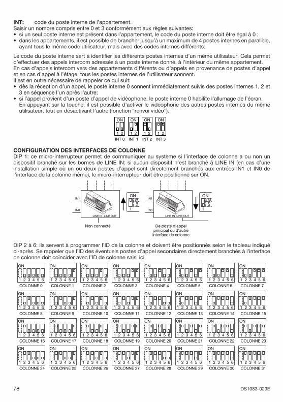
78 DS1083-029E
INT: code du poste interne de l’appartement.Saisir un nombre compris entre 0 et 3 conformément aux règles suivantes:
si un seul poste interne est présent dans l’appartement, le code du poste interne doit être égal à 0 ;dans les appartements, il est possible de brancher jusqu’à un maximum de 4 postes internes en parallèle, ayant tous le même code utilisateur, mais avec des codes internes différents.
Le code du poste interne sert à identifi er les différents postes internes d’un même utilisateur. Cela permet d’effectuer des appels intercom adressés à un poste interne donné, à l’intérieur du même appartement. En cas d’appels intercom vers des appartements différents ou d’appels en provenance de postes d’appel et en cas d’appel à l’étage, tous les postes internes de l’utilisateur sonnent.Il est en outre nécessaire de rappeler ce qui suit:
dès la réception d’un appel, le poste interne 0 sonnent immédiatement suivis des postes internes 1, 2 et 3 en séquence l’un après l’autre; si l’appel provient d’un poste d’appel de vidéophone, le poste interne 0 habilite l’allumage de l’écran.
En appuyant sur la touche, il est possible d’activer le vidéophone des autres postes internes du même utilisateur, tout en désactivant l’autre (fonction “renvoi vidéo”).
21
INT 1
ON
21
INT 0
ON
21
INT 2
ON
21
INT 3
ON
CONFIGURATION DES INTERFACES DE COLONNEDIP 1: ce micro-interrupteur permet de communiquer au système si l’interface de colonne a ou non un dispositif branché sur les bornes de LINE IN: si aucun dispositif n’est branché à LINE IN (en cas d’une installation simple où un ou deux postes d’appel sont directement branchés aux entrées IN1 et IN0 de l’interface de la colonne même), le micro-interrupteur doit être positionné sur ON.
LINE IN LINE OUT
ON
1
De poste d’appelprincipal ou d’autreinterface de colonne
Non connecté
LINE IN LINE OUT
ON
1
IN1
IN0
IN1
IN0
DIP 2 à 6: ils servent à programmer l’ID de la colonne et doivent être positionnés selon le tableau indiqué ci-après. Se rappeler que l’ID des éventuels postes d’appel secondaires directement branchés à l’interface de colonne doit coïncider avec l’ID de colonne saisi ici.
ON
COLONNE 0
654321
ON
COLONNE 1
654321
ON
COLONNE 2
654321
ON
COLONNE 3
654321
ON
COLONNE 4
654321
ON
COLONNE 5
654321
ON
COLONNE 6
654321
ON
COLONNE 7
654321
ON
COLONNE 8
654321
ON
COLONNE 9
654321
ON
COLONNE 10
654321
ON
COLONNE 11
654321
ON
COLONNE 12
654321
ON
COLONNE 13
654321
ON
COLONNE 14
654321
ON
COLONNE 15
654321
ON
COLONNE 24
654321
ON
COLONNE 25
654321
ON
COLONNE 26
654321
ON
COLONNE 27
654321
ON
COLONNE 28
654321
ON
COLONNE 29
654321
ON
COLONNE 30
654321
ON
COLONNE 31
654321
ON
COLONNE 16
654321
ON
COLONNE 17
654321
ON
COLONNE 18
654321
ON
COLONNE 19
654321
ON
COLONNE 20
654321
ON
COLONNE 21
654321
ON
COLONNE 22
654321
ON
COLONNE 23
654321
••
•
•
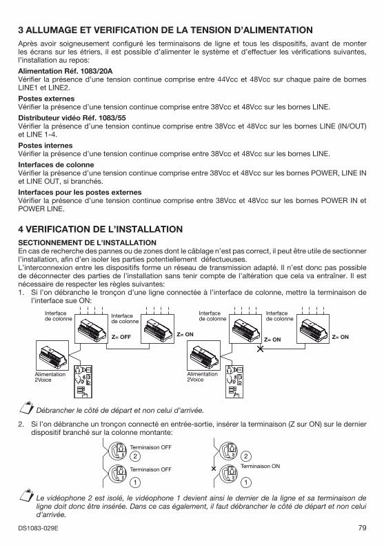
79DS1083-029E
3 ALLUMAGE ET VERIFICATION DE LA TENSION D’ALIMENTATION Après avoir soigneusement confi guré les terminaisons de ligne et tous les dispositifs, avant de monter les écrans sur les étriers, il est possible d’alimenter le système et d’effectuer les vérifi cations suivantes, l’installation au repos:
Alimentation Réf. 1083/20AVérifi er la présence d’une tension continue comprise entre 44Vcc et 48Vcc sur chaque paire de bornes LINE1 et LINE2.
Postes externesVérifi er la présence d’une tension continue comprise entre 38Vcc et 48Vcc sur les bornes LINE.
Distributeur vidéo Réf. 1083/55Vérifi er la présence d’une tension continue comprise entre 38Vcc et 48Vcc sur les bornes LINE (IN/OUT) et LINE 1-4.
Postes internesVérifi er la présence d’une tension continue comprise entre 38Vcc et 48Vcc sur les bornes LINE.
Interfaces de colonneVérifi er la présence d’une tension continue comprise entre 38Vcc et 48Vcc sur les bornes POWER, LINE IN et LINE OUT, si branchés.
Interfaces pour les postes externesVérifi er la présence d’une tension continue comprise entre 38Vcc et 48Vcc sur les bornes POWER IN et POWER LINE.
4 VERIFICATION DE L’INSTALLATIONSECTIONNEMENT DE L’INSTALLATION En cas de recherche des pannes ou de zones dont le câblage n’est pas correct, il peut être utile de sectionner l’installation, afi n d’en isoler les parties potentiellement défectueuses.L’interconnexion entre les dispositifs forme un réseau de transmission adapté. Il n’est donc pas possible de déconnecter des parties de l’installation sans tenir compte de l’altération que cela va entraîner. Il est nécessaire de respecter les règles suivantes:1. Si l’on débranche le tronçon d’une ligne connectée à l’interface de colonne, mettre la terminaison de
l’interface sue ON:
TC TC
Alimentation2Voice
Alimentation2Voice
Z= OFF
Interfacede colonne
Interfacede colonne
Z= ON
Interfacede colonne
Z= ON
Interfacede colonne
Z= ON
Débrancher le côté de départ et non celui d’arrivée.
2. Si l’on débranche un tronçon connecté en entrée-sortie, insérer la terminaison (Z sur ON) sur le dernier dispositif branché sur la colonne montante:
Terminaison OFF
Terminaison OFFTerminaison ON
11
22
Le vidéophone 2 est isolé, le vidéophone 1 devient ainsi le dernier de la ligne et sa terminaison de ligne doit donc être insérée. Dans ce cas également, il faut débrancher le côté de départ et non celui d’arrivée.
§
§
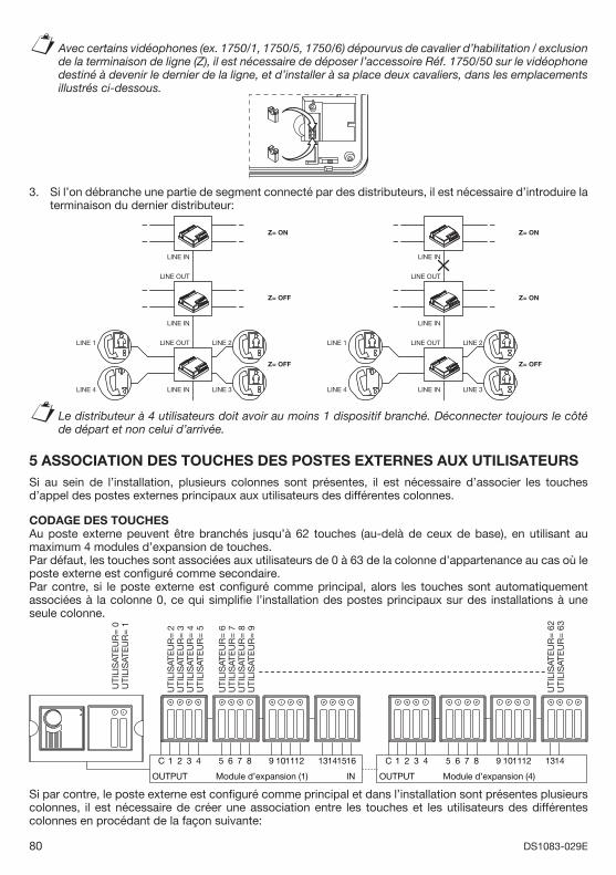
80 DS1083-029E
Avec certains vidéophones (ex. 1750/1, 1750/5, 1750/6) dépourvus de cavalier d’habilitation / exclusion de la terminaison de ligne (Z), il est nécessaire de déposer l’accessoire Réf. 1750/50 sur le vidéophone destiné à devenir le dernier de la ligne, et d’installer à sa place deux cavaliers, dans les emplacements illustrés ci-dessous.
3. Si l’on débranche une partie de segment connecté par des distributeurs, il est nécessaire d’introduire la terminaison du dernier distributeur:
LINE IN
LINE OUT
LINE IN
LINE OUTLINE 1
Z= ON
Z= OFF
Z= OFF
LINE INLINE 4
LINE 2
LINE 3
LINE IN
LINE OUT
LINE IN
LINE OUTLINE 1
Z= ON
Z= ON
Z= OFF
LINE INLINE 4
LINE 2
LINE 3
Le distributeur à 4 utilisateurs doit avoir au moins 1 dispositif branché. Déconnecter toujours le côté de départ et non celui d’arrivée.
5 ASSOCIATION DES TOUCHES DES POSTES EXTERNES AUX UTILISATEURSSi au sein de l’installation, plusieurs colonnes sont présentes, il est nécessaire d’associer les touches d’appel des postes externes principaux aux utilisateurs des différentes colonnes.
CODAGE DES TOUCHESAu poste externe peuvent être branchés jusqu’à 62 touches (au-delà de ceux de base), en utilisant au maximum 4 modules d’expansion de touches.Par défaut, les touches sont associées aux utilisateurs de 0 à 63 de la colonne d’appartenance au cas où le poste externe est confi guré comme secondaire. Par contre, si le poste externe est confi guré comme principal, alors les touches sont automatiquement associées à la colonne 0, ce qui simplifi e l’installation des postes principaux sur des installations à une seule colonne.
UTI
LIS
ATE
UR
= 2
UTI
LIS
ATE
UR
= 3
UTI
LIS
ATE
UR
= 0
UTI
LIS
ATE
UR
= 1
UTI
LIS
ATE
UR
= 4
UTI
LIS
ATE
UR
= 5
UTI
LIS
ATE
UR
= 6
UTI
LIS
ATE
UR
= 7
UTI
LIS
ATE
UR
= 8
UTI
LIS
ATE
UR
= 9
C 321 4 765 8 11109 12 151413 16
OUTPUT Module d’expansion (1) IN
UTI
LIS
ATE
UR
= 6
2U
TILI
SAT
EU
R=
63
C 321 4 765 8 11109 12 1413
OUTPUT Module d’expansion (4)
Si par contre, le poste externe est confi guré comme principal et dans l’installation sont présentes plusieurs colonnes, il est nécessaire de créer une association entre les touches et les utilisateurs des différentes colonnes en procédant de la façon suivante:
§
§
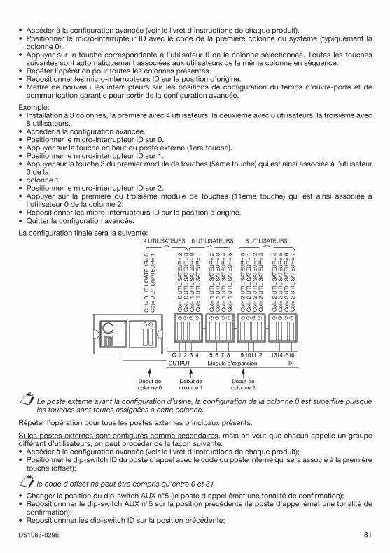
81DS1083-029E
Accéder à la confi guration avancée (voir le livret d’instructions de chaque produit).Positionner le micro-interrupteur ID avec le code de la première colonne du système (typiquement la colonne 0).Appuyer sur la touche correspondante à l’utilisateur 0 de la colonne sélectionnée. Toutes les touches suivantes sont automatiquement associées aux utilisateurs de la même colonne en séquence.Répéter l’opération pour toutes les colonnes présentes.Repositionner les micro-interrupteurs ID sur la position d’origine.Mettre de nouveau les interrupteurs sur les positions de confi guration du temps d’ouvre-porte et de communication garantie pour sortir de la confi guration avancée.
Exemple:Installation à 3 colonnes, la première avec 4 utilisateurs, la deuxième avec 6 utilisateurs, la troisième avec 8 utilisateurs.Accéder à la confi guration avancée.Positionner le micro-interrupteur ID sur 0.Appuyer sur la touche en haut du poste externe (1ère touche).Positionner le micro-interrupteur ID sur 1.Appuyer sur la touche 3 du premier module de touches (5ème touche) qui est ainsi associée à l’utilisateur 0 de lacolonne 1.Positionner le micro-interrupteur ID sur 2.Appuyer sur la première du troisième module de touches (11ème touche) qui est ainsi associée à l’utilisateur 0 de la colonne 2.Repositionner les micro-interrupteurs ID sur la position d’origine.Quitter la confi guration avancée.
La confi guration fi nale sera la suivante:
Col
= 0
UTI
LIS
ATE
UR
= 2
Col
= 0
UTI
LIS
ATE
UR
= 3
Col
= 0
UTI
LIS
ATE
UR
= 0
Col
= 0
UTI
LIS
ATE
UR
= 1
Col
= 1
UTI
LIS
ATE
UR
= 0
Col
= 1
UTI
LIS
ATE
UR
= 1
Col
= 1
UTI
LIS
ATE
UR
= 2
Col
= 1
UTI
LIS
ATE
UR
= 3
Col
= 1
UTI
LIS
ATE
UR
= 4
Col
= 1
UTI
LIS
ATE
UR
= 5
Col
= 2
UTI
LIS
ATE
UR
= 0
Col
= 2
UTI
LIS
ATE
UR
= 1
Col
= 2
UTI
LIS
ATE
UR
= 2
Col
= 2
UTI
LIS
ATE
UR
= 3
Col
= 2
UTI
LIS
ATE
UR
= 4
Col
= 2
UTI
LIS
ATE
UR
= 5
Col
= 2
UTI
LIS
ATE
UR
= 6
Col
= 2
UTI
LIS
ATE
UR
= 7
C 321 4 765 8 11109 12 151413 16
OUTPUT Module d’expansion IN
4 UTILISATEURS 6 UTILISATEURS 8 UTILISATEURS
Début decolonne 0
Début decolonne 1
Début decolonne 2
Le poste externe ayant la confi guration d’usine, la confi guration de la colonne 0 est superfl ue puisque les touches sont toutes assignées à cette colonne.
Répéter l’opération pour tous les postes externes principaux présents.
Si les postes externes sont confi gurés comme secondaires, mais on veut que chacun appelle un groupe différent d’utilisateurs, on peut procéder de la façon suivante:
Accéder à la confi guration avancée (voir le livret d’instructions de chaque produit); Positionner le dip-switch ID du poste d’appel avec le code du poste interne qui sera associé à la première touche (offset);
le code d’offset ne peut être compris qu’entre 0 et 31
Changer la position du dip-switch AUX n°5 (le poste d’appel émet une tonalité de confi rmation);Repositionnner le dip-switch AUX n°5 sur la position précédente (le poste d’appel émet une tonalité de confi rmation);Repositionnner les dip-switch ID sur la position précédente;
••
•
•••
•
•••••
•••
••
§
••
§••
•
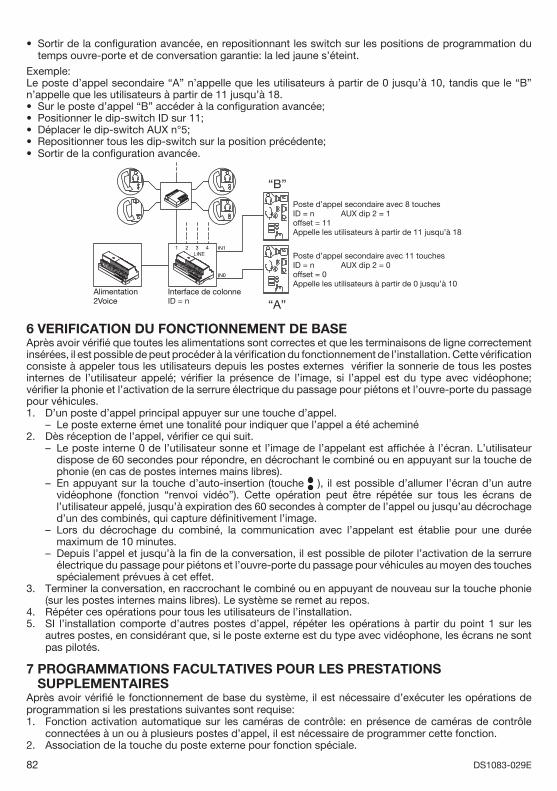
82 DS1083-029E
Sortir de la confi guration avancée, en repositionnant les switch sur les positions de programmation du temps ouvre-porte et de conversation garantie: la led jaune s’éteint.
Exemple: Le poste d’appel secondaire “A” n’appelle que les utilisateurs à partir de 0 jusqu’à 10, tandis que le “B” n’appelle que les utilisateurs à partir de 11 jusqu’à 18.
Sur le poste d’appel “B” accéder à la confi guration avancée;Positionner le dip-switch ID sur 11;Déplacer le dip-switch AUX n°5;Repositionner tous les dip-switch sur la position précédente; Sortir de la confi guration avancée.
“B”
“A”Alimentation2Voice
Interface de colonneID = n
Poste d’appel secondaire avec 8 touchesID = n AUX dip 2 = 1offset = 11Appelle les utilisateurs à partir de 11 jusqu’à 18
Poste d’appel secondaire avec 11 touchesID = n AUX dip 2 = 0offset = 0Appelle les utilisateurs à partir de 0 jusqu’à 10
6 VERIFICATION DU FONCTIONNEMENT DE BASEAprès avoir vérifi é que toutes les alimentations sont correctes et que les terminaisons de ligne correctement insérées, il est possible de peut procéder à la vérifi cation du fonctionnement de l’installation. Cette vérifi cation consiste à appeler tous les utilisateurs depuis les postes externes vérifi er la sonnerie de tous les postes internes de l’utilisateur appelé; vérifi er la présence de l’image, si l’appel est du type avec vidéophone; vérifi er la phonie et l’activation de la serrure électrique du passage pour piétons et l’ouvre-porte du passage pour véhicules. 1. D’un poste d’appel principal appuyer sur une touche d’appel.
Le poste externe émet une tonalité pour indiquer que l’appel a été acheminé2. Dès réception de l’appel, vérifi er ce qui suit.
Le poste interne 0 de l’utilisateur sonne et l’image de l’appelant est affi chée à l’écran. L’utilisateur dispose de 60 secondes pour répondre, en décrochant le combiné ou en appuyant sur la touche de phonie (en cas de postes internes mains libres).En appuyant sur la touche d’auto-insertion (touche ), il est possible d’allumer l’écran d’un autre vidéophone (fonction “renvoi vidéo”). Cette opération peut être répétée sur tous les écrans de l’utilisateur appelé, jusqu’à expiration des 60 secondes à compter de l’appel ou jusqu’au décrochage d’un des combinés, qui capture défi nitivement l’image. Lors du décrochage du combiné, la communication avec l’appelant est établie pour une durée maximum de 10 minutes.Depuis l’appel et jusqu’à la fi n de la conversation, il est possible de piloter l’activation de la serrure électrique du passage pour piétons et l’ouvre-porte du passage pour véhicules au moyen des touches spécialement prévues à cet effet.
3. Terminer la conversation, en raccrochant le combiné ou en appuyant de nouveau sur la touche phonie (sur les postes internes mains libres). Le système se remet au repos.
4. Répéter ces opérations pour tous les utilisateurs de l’installation.5. SI l’installation comporte d’autres postes d’appel, répéter les opérations à partir du point 1 sur les
autres postes, en considérant que, si le poste externe est du type avec vidéophone, les écrans ne sont pas pilotés.
7 PROGRAMMATIONS FACULTATIVES POUR LES PRESTATIONS SUPPLEMENTAIRESAprès avoir vérifi é le fonctionnement de base du système, il est nécessaire d’exécuter les opérations de programmation si les prestations suivantes sont requise:1. Fonction activation automatique sur les caméras de contrôle: en présence de caméras de contrôle
connectées à un ou à plusieurs postes d’appel, il est nécessaire de programmer cette fonction.2. Association de la touche du poste externe pour fonction spéciale.
•
•••••
–
–
–
–
–
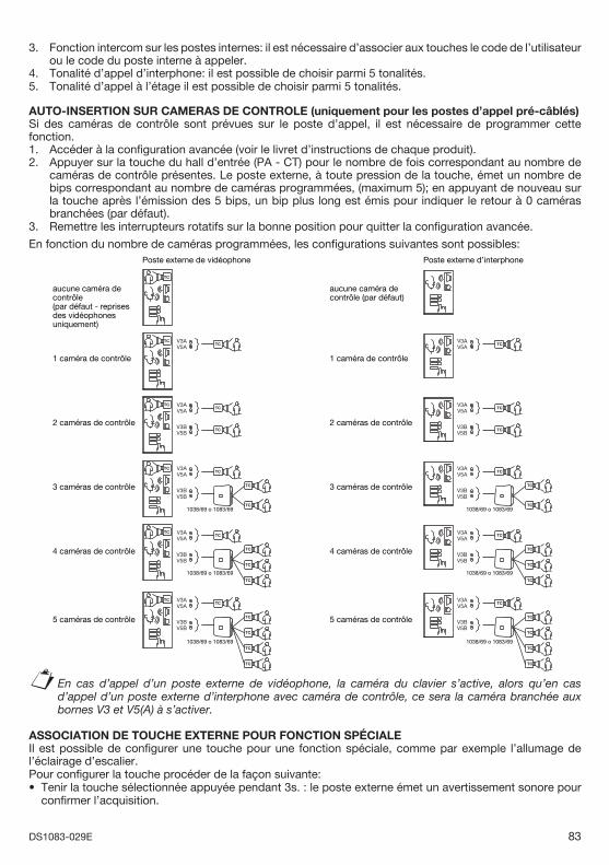
83DS1083-029E
3. Fonction intercom sur les postes internes: il est nécessaire d’associer aux touches le code de l’utilisateur ou le code du poste interne à appeler.
4. Tonalité d’appel d’interphone: il est possible de choisir parmi 5 tonalités. 5. Tonalité d’appel à l’étage il est possible de choisir parmi 5 tonalités.
AUTO-INSERTION SUR CAMERAS DE CONTROLE (uniquement pour les postes d’appel pré-câblés)Si des caméras de contrôle sont prévues sur le poste d’appel, il est nécessaire de programmer cette fonction.1. Accéder à la confi guration avancée (voir le livret d’instructions de chaque produit).2. Appuyer sur la touche du hall d’entrée (PA - CT) pour le nombre de fois correspondant au nombre de
caméras de contrôle présentes. Le poste externe, à toute pression de la touche, émet un nombre de bips correspondant au nombre de caméras programmées, (maximum 5); en appuyant de nouveau sur la touche après l’émission des 5 bips, un bip plus long est émis pour indiquer le retour à 0 caméras branchées (par défaut).
3. Remettre les interrupteurs rotatifs sur la bonne position pour quitter la confi guration avancée.
En fonction du nombre de caméras programmées, les confi gurations suivantes sont possibles:
TC
TC
TC
TC
TC
TC
TC
TC
TC
TC
TC
TC
TC
TC
TC
TC
TC
TC
TC
TC
TC TC
TC
TC
TC
TC
TC
TC
TC
V3AV5A
V3AV5A
V3BV5B
V3AV5A
V3BV5B
V3AV5A
V3BV5B
V3AV5A
V3BV5B
TC
TC
TC
TC
TC
TC
TC
Poste externe de vidéophone Poste externe d’interphone
aucune caméra de contrôle(par défaut - reprises des vidéophones uniquement)
2 caméras de contrôle
3 caméras de contrôle
4 caméras de contrôle
1 caméra de contrôle
5 caméras de contrôle
aucune caméra de contrôle (par défaut)
2 caméras de contrôle
3 caméras de contrôle
4 caméras de contrôle
1 caméra de contrôle
5 caméras de contrôle
V3AV5A
V3AV5A
V3BV5B
V3AV5A
V3BV5B
V3AV5A
V3BV5B
V3AV5A
V3BV5B
1038/69 o 1083/69
1038/69 o 1083/69
1038/69 o 1083/69
1038/69 o 1083/69
1038/69 o 1083/69
1038/69 o 1083/69
En cas d’appel d’un poste externe de vidéophone, la caméra du clavier s’active, alors qu’en cas d’appel d’un poste externe d’interphone avec caméra de contrôle, ce sera la caméra branchée aux bornes V3 et V5(A) à s’activer.
ASSOCIATION DE TOUCHE EXTERNE POUR FONCTION SPÉCIALE Il est possible de confi gurer une touche pour une fonction spéciale, comme par exemple l’allumage de l’éclairage d’escalier.Pour confi gurer la touche procéder de la façon suivante:
Tenir la touche sélectionnée appuyée pendant 3s. : le poste externe émet un avertissement sonore pour confi rmer l’acquisition.
§
•
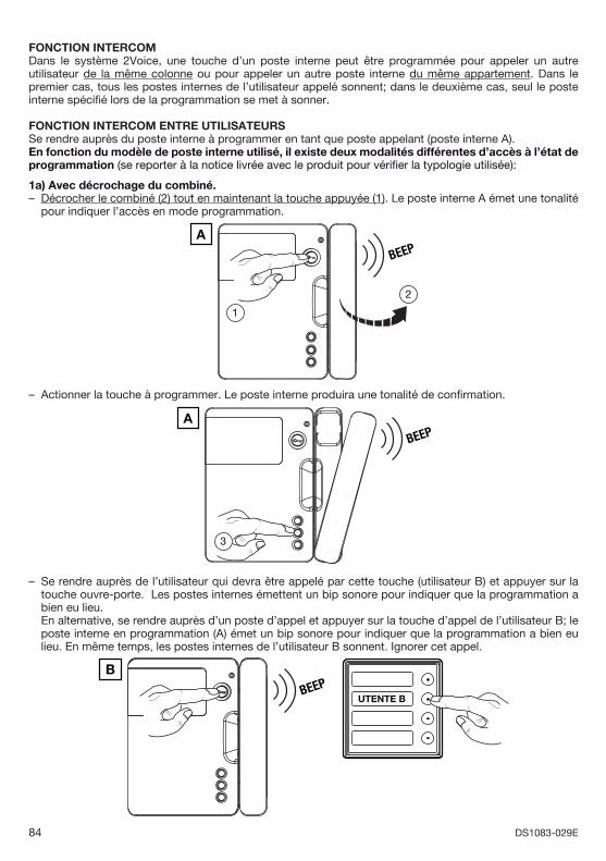
84 DS1083-029E
FONCTION INTERCOM Dans le système 2Voice, une touche d’un poste interne peut être programmée pour appeler un autre utilisateur de la même colonne ou pour appeler un autre poste interne du même appartement. Dans le premier cas, tous les postes internes de l’utilisateur appelé sonnent; dans le deuxième cas, seul le poste interne spécifi é lors de la programmation se met à sonner.
FONCTION INTERCOM ENTRE UTILISATEURSSe rendre auprès du poste interne à programmer en tant que poste appelant (poste interne A).En fonction du modèle de poste interne utilisé, il existe deux modalités différentes d’accès à l’état de programmation (se reporter à la notice livrée avec le produit pour vérifi er la typologie utilisée):
1a) Avec décrochage du combiné.Décrocher le combiné (2) tout en maintenant la touche appuyée (1). Le poste interne A émet une tonalité pour indiquer l’accès en mode programmation.
BEEPA
2
1
Actionner la touche à programmer. Le poste interne produira une tonalité de confi rmation.
BEEPA
3
Se rendre auprès de l’utilisateur qui devra être appelé par cette touche (utilisateur B) et appuyer sur la touche ouvre-porte. Les postes internes émettent un bip sonore pour indiquer que la programmation a bien eu lieu.
En alternative, se rendre auprès d’un poste d’appel et appuyer sur la touche d’appel de l’utilisateur B; le poste interne en programmation (A) émet un bip sonore pour indiquer que la programmation a bien eu lieu. En même temps, les postes internes de l’utilisateur B sonnent. Ignorer cet appel.
BEEPB
UTENTE B
–
–
–
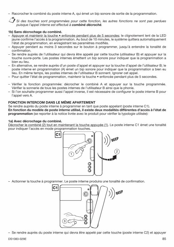
85DS1083-029E
Raccrocher le combiné du poste interne A, qui émet un bip sonore de sortie de la programmation.
Si des touches sont programmées pour cette fonction, les autres fonctions ne sont pas perdues puisque l’appel interne est effectué à combiné décroché.
1b) Sans décrochage du combiné.Appuyer et maintenir la touche • enfoncée pendant plus de 5 secondes; le clignotement lent de la LED jaune confi rme l’accès à la programmation. Au bout de 10 minutes, le système quittera automatiquement l’état de programmation, en enregistrant les paramètres modifi és.Appuyer pendant au moins 3 secondes sur le bouton à programmer, jusqu’à entendre la tonalité de confi rmation.Se rendre auprès de l’utilisateur qui devra être appelé par cette touche (utilisateur B) et appuyer sur la touche ouvre-porte. Les postes internes émettent un bip sonore pour indiquer que la programmation a bien eu lieu. En alternative, se rendre auprès d’un poste d’appel et appuyer sur la touche d’appel de l’utilisateur B; le poste interne en programmation (A) émet un bip sonore pour indiquer que la programmation a bien eu lieu. En même temps, les postes internes de l’utilisateur B sonnent. Ignorer cet appel.Pour quitter l’état de programmation, maintenir la touche • enfoncée pendant plus de 5 secondes.
Vérifi er la fonction programmée: décrocher le combiné A et appuyer sur la touche programmée.Vérifi er la sonnerie de tous les postes internes de l’utilisateur B ainsi que la phonie.Si l’on souhaite programmer aussi l’appel inverse, il est nécessaire de confi gurer le poste interne B pour l’appel vers A.
FONCTION INTERCOM DANS LE MÊME APARTEMENTSe rendre auprès du poste interne à programmer en tant que poste appelant (poste interne C1).En fonction du modèle de poste interne utilisé, il existe deux modalités différentes d’accès à l’état de programmation (se reporter à la notice livrée avec le produit pour vérifi er la typologie utilisée):
1a) Avec décrochage du combiné.Décrocher le combiné (2) tout en maintenant la touche appuyée (1). Le poste interne C1 émet une tonalité pour indiquer l’accès en mode programmation touches.
BEEPC1
21
Actionner la touche à programmer. Le poste interne produira une tonalité de confi rmation.
BEEPC1
3
Se rendre auprès du poste interne qui devra être appelé par cette touche (poste interne C2) et appuyer
–
§
–
–
–
–
–
–
–
–
–
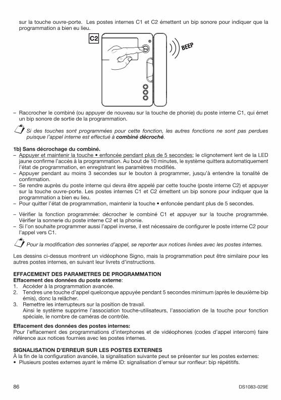
86 DS1083-029E
sur la touche ouvre-porte. Les postes internes C1 et C2 émettent un bip sonore pour indiquer que la programmation a bien eu lieu.
BEEPC2
Raccrocher le combiné (ou appuyer de nouveau sur la touche de phonie) du poste interne C1, qui émet un bip sonore de sortie de la programmation.
Si des touches sont programmées pour cette fonction, les autres fonctions ne sont pas perdues puisque l’appel interne est effectué à combiné décroché.
1b) Sans décrochage du combiné.Appuyer et maintenir la touche • enfoncée pendant plus de 5 secondes; le clignotement lent de la LED jaune confi rme l’accès à la programmation. Au bout de 10 minutes, le système quittera automatiquement l’état de programmation, en enregistrant les paramètres modifi és.Appuyer pendant au moins 3 secondes sur le bouton à programmer, jusqu’à entendre la tonalité de confi rmation.Se rendre auprès du poste interne qui devra être appelé par cette touche (poste interne C2) et appuyer sur la touche ouvre-porte. Les postes internes C1 et C2 émettent un bip sonore pour indiquer que la programmation a bien eu lieu.Pour quitter l’état de programmation, maintenir la touche • enfoncée pendant plus de 5 secondes.
Vérifi er la fonction programmée: décrocher le combiné C1 et appuyer sur la touche programmée. Vérifi er la sonnerie du poste interne C2 et la phonie.Si l’on souhaite programmer aussi l’appel inverse, il est nécessaire de confi gurer le poste interne C2 pour l’appel vers C1.
Pour la modifi cation des sonneries d’appel, se reporter aux notices livrées avec les postes internes.
Les dessins ci-dessus montrent un vidéophone Signo, mais la programmation peut être similaire pour les autres postes internes, en suivant leur livrets d’instructions.
EFFACEMENT DES PARAMETRES DE PROGRAMMATION Effacement des données du poste externe:1. Accéder à la programmation avancée.2. Tendres une touche d’appel quelconque appuyée pendant 5 secondes minimum (après le deuxième bip
émis), donc la relâcher.3. Remettre les interrupteurs sur la position de travail. Ainsi le système supprime l’association touche-utilisateurs, l’association de la touche pour fonction
spéciale, le nombre de caméras de contrôle.
Effacement des données des postes internes:Pour l’effacement des programmations d’interphones et de vidéophones (codes d’appel intercom) faire référence aux notices fournies avec les postes internes.
SIGNALISATION D’ERREUR SUR LES POSTES EXTERNESÀ la fi n de la confi guration avancée, la signalisation suivante peut se présenter sur les postes externes:
Plusieurs postes externes ayant le même ID: signalisation d’erreur sur ronfl eur: bip répétitifs.
–
§
–
–
–
–
–
–
§
•
87DS1083-029E
CARACTERISTIQUES TECHNIQUES DE DISPOSITIFSDistributeur à 4 utilisateurs Réf. 1083/55Tension d’alimentation: ...............................................................................................................36 – 48V Absorption maximale: ................................................................................................................... 9,0mA max Température de fonctionnement: ............................................................................................. - 5°C ÷ + 45°CDimensions: ............................................................................................................................45 x 45 x 16mm
Alimentation Réf 1083/20AAlimentation en CAT II 2500 V. L’alimentateur, qui une fois installé peut subir des tensions transitoires supérieures à celles de la catégorie de surtension de projet, nécessite une protection supplémentaire des tensions transitoires externes à l’équipement.
Alimentation: ...................................................................................................110-230V~ +/- 10% 50 / 60HzPuissance: .................................................................................................................................................80WSortie LINE 1/2: ................................................................................................................................... 48V
avec protection électronique contre les surcharges de courantTempérature de fonctionnement: ........................................................................................... - 10°C ÷ + 35°CDimensions: ............................................................................................180 x 80 x 90mm (10 modules DIN)Poids: ...................................................................................................................................... 1.000g environ
LÉGENDES SYMBOLESSymbole Explication
Tension d’alimentation continue
~ Tension d’alimentation alternée
Se reporter au manuel d’installation du dispositif
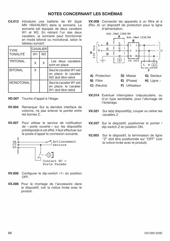
88 DS1083-029E
NOTES CONCERNANT LES SCHÉMAS
C4.013 Introduire une batterie de 9V (type MN 1604/6LR61) dans la sonnerie. La sonnerie est équipée de deux cavaliers W1 et W2. En retirant l’un des deux cavaliers, la sonnerie peut fonctionner en mode bitonal ou monotonal, selon le tableau suivant:
TYPE TONALITÉ
CAVALIER
W1 W2
TRITONAL X X Les deux cavaliers sont en place
BITONAL X Seul le cavalier W1 est en place: le cavalier W2 doit être retiré
MONOTONAL Seul le cavalier W1 est en place: le cavalier W1 doit être retiré
VD.007 Touche d’appel à l’étage.
VV.004 Remarque: Sur la dernière interface de colonne, ne pas enlever le pontet entre les bornes Z.
VV.007 Pour utiliser le service de notifi cation de « porte ouverte » sur les dispositifs prédisposés à cet effet, il faut effectuer sur le poste d’appel la connexion suivante.
ActionnementSerrure
Contact NC =Porte Fermée
VV.008 Confi gurer le dip-switch «1» en position OFF.
VX.006 Pour le montage de l’accessoire dans le dispositif, voir la notice livrée avec le produit.
VX.008 Connecter les appareils à un fi ltre et à un dispositif de protection pour la ligne d’alimentation.
Sch./Ref.1382/85Sch./Ref.1332/86A
B
C
D
E
F
GH
A) Protection
B) Filtre
C) (Neutre)
D) Masse
E) (Phase)
F) Utilisateur
G) Secteur
H) Ligne ~
L
NL
N
NL
230
Vca
OUTIN
1 1
22
VX.014 Eventuel interrupteur crépusculaire, ou d’un type semblable, pour l’allumage de l’éclairage.
VX.021 Sur le(s) dispositif(s), couper ou retirer les cavaliers Z.
VX.037 Sur le dispositif, positionner le pontet / dip-switch Z en position ON.
V2.003 Sur le dispositif, la terminaison de ligne “Z” doit être positionnée sur “OFF” (voir la notice livrée avec le produit).
(Rev. A)
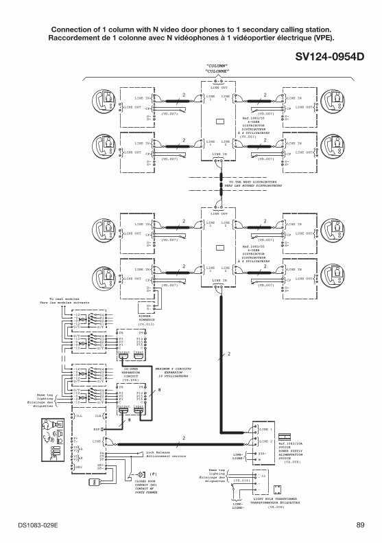
89DS1083-029E
Connection of 1 column with N video door phones to 1 secondary calling station.Raccordement de 1 colonne avec N vidéophones à 1 vidéoportier électrique (VPE).
SV124-0954D"COLUMN”“COLONNE”
Ref.1083/554-USER
DISTRIBUTORDISTRIBUTEUR
À 4 UTILISATEURS
Ref.1083/554-USER
DISTRIBUTORDISTRIBUTEUR
À 4 UTILISATEURS
RINGERSONNERIE
To next modulesVers les modules suivants
16-USEREXPANSIONCIRCUIT
Lock ReleaseActionnement serrure
TO THE NEXT DISTRIBUTORSVERS LES AUTRES DISTRIBUTEURS
MAXIMUM 4 CIRCUITSEXPANSION
16 UTILISATEURS
Name taglighting
Éclairage desétiquettes
Name taglighting
Éclairage desétiquettesCLOSED DOOR
CONTACT (NC)CONTACT NFPORTE FERMÉE
LINE~LIGNE~
LINE~LIGNE~
230~
N
Ref.1083/20A2VOICEPOWER SUPPLYALIMENTATION2VOICE
LIGHT BULB TRANSFORMERTRANSFORMATEUR ÉTIQUETTES
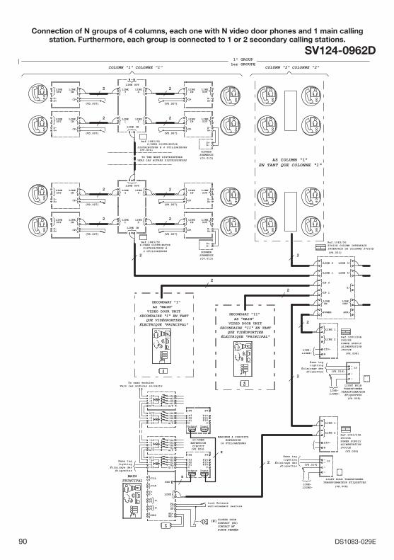
90 DS1083-029E
Connection of N groups of 4 columns, each one with N video door phones and 1 main calling station. Furthermore, each group is connected to 1 or 2 secondary calling stations.
SV124-0962D
(VX.014)
(VX.008)
(VD.007)(VD.007)
22
(VD.007)(VD.007)
22
(VD.007)(VD.007)
22
(VD.007) (VD.007)
(VX.008)
2 2
(VX.014)
(VX.008)
2
2
2
2
2
AS COLUMN "1”EN TANT QUE COLONNE “1“
1° GROUP1er GROUPE
COLUMN "2" COLONNE "2" COLUMN "1" COLONNE "1"
2
(VX.006)
(#)
MAINPRINCIPAL
2
(VV.001)
(VX.021)
SECONDARY "II"
SECONDARY "I"
~~
~
12
~
~~
~
12
~
LINE 4
LINE 3
LINE 1
LINE 2
LINE
AUX
LINE
IN 1
OUT
POWER
IN
IN 0
Z
InputOutputC
..
P1P2P3
P8 P9
C
P14P15P16
..
LINE 1
LINE 2
N
230~
LINELINE
CPS+S-
OUT IN
LINELINE
CPS+S-
OUT IN
CP S+S-
OUTLINELINE
IN
S-S+
LINE 1
LINE 2
N
230~
CP S+S-
OUTLINELINE
INLINE1
LINE2
3LINE LINE
4
LINE OUT
LINE IN
U2U3
G/T
U4
U1
~12
G/T
~0U1
G/TU3U2
~12~0
U4
~12~0~0~12G/T
CP S+S-
OUTLINELINE
IN
InputOutputC
..
P1P2P3
P8 P9
C
P14P15P16
..
LINELINE
CPS+S-
OUT IN
LINE1
LINE2
3LINE LINE
4
LINE OUT
LINE IN
LINELINE
CPS+S-
OUT IN
S-S+
U2U3
G/T
U4
U1
~12
G/T
~0U1
G/TU3U2
~12~0
U4
~12~0~0~12G/T
CT
V3
SE+
T+
PA
T- LINE
V5
V3 SPV5
SE-SE2
ILL
ILA
A
B
ESP
CP S+S-
OUTLINELINE
IN
4-USER DISTRIBUTORDISTRIBUTEUR À4 UTILISATEURS
4-USER DISTRIBUTORDISTRIBUTEUR À 4 UTILISATEURS
TO THE NEXT DISTRIBUTORSVERS LES AUTRES DISTRIBUTEURS
To next modulesVers les modules suivants
16-USEREXPANSIONCIRCUIT
MAXIMUM 4 CIRCUITSEXPANSION
16 UTILISATEURS
Ref.1083/55
(C4.013)
RINGERSONNERIE
(C4.013)
RINGERSONNERIE
Ref.1083/55
Lock ReleaseActionnement serrure
LINE~LIGNE~
LIGHT BULB TRANSFORMERTRANSFORMATEUR ÉTIQUETTES
Ref.1083/20A2VOICEPOWER SUPPLYALIMENTATION2VOICE
Name taglighting
Éclairage desétiquettes
Name taglighting
Éclairage desétiquettes
LINE~LIGNE~
LINE~LIGNE~
LIGHT BULBTRANSFORMER
TRANSFORMATEURÉTIQUETTES
Name taglighting
Éclairage desétiquettes
Ref.1083/502VOICE COLUMN INTERFACEINTERFACE DE COLONNE 2VOICE
AS “MAIN” VIDEO DOOR UNIT
SECONDAIRE “I“ EN TANTQUE VIDÉOPORTIER
ÉLECTRIQUE “PRINCIPAL“
AS “MAIN” VIDEO DOOR UNIT
SECONDAIRE “II“ EN TANTQUE VIDÉOPORTIER
ÉLECTRIQUE “PRINCIPAL“
CLOSED DOORCONTACT (NC)CONTACT NFPORTE FERMÉE
(VX.008)
Ref.1083/20A2VOICEPOWER SUPPLYALIMENTATION2VOICE
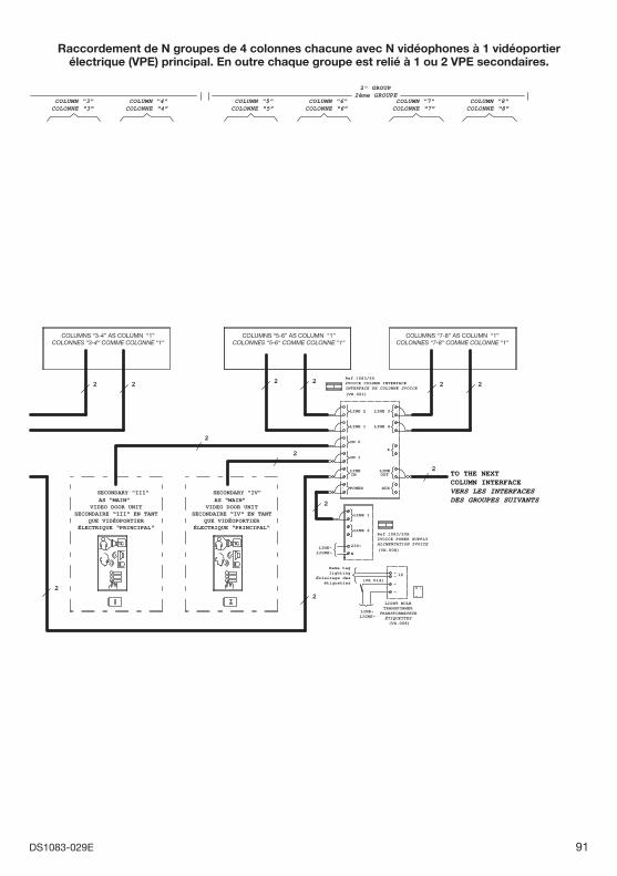
91DS1083-029E
COLUMN "3"COLONNE “3”
COLUMN "4"COLONNE “4”
COLUMN "5"COLONNE “5”
COLUMN "6"COLONNE “6”
COLUMN "7"COLONNE “7”
COLUMN "8"COLONNE “8”
(VX.014)
(VX.008)
2
(VX.008)
2
2
2
2
2
2 2(VX.021)
22 2 2
LINE 4
LINE 3
LINE 1
LINE 2
LINE
AUX
LINE
IN 1
OUT
POWER
IN
IN 0
Z
~~
~
12
~
LINE 1
LINE 2
N
230~LINE~LIGNE~
LINE~LIGNE~
Ref.1083/20A2VOICE POWER SUPPLYALIMENTATION 2VOICE
Ref.1083/502VOICE COLUMN INTERFACEINTERFACE DE COLONNE 2VOICE
COLUMNS “3-4” AS COLUMN “1”COLONNES “3-4“ COMME COLONNE “1“
COLUMNS “5-6” AS COLUMN “1”COLONNES “5-6“ COMME COLONNE “1“
COLUMNS “7-8” AS COLUMN “1”COLONNES “7-8“ COMME COLONNE “1“
TO THE NEXTCOLUMN INTERFACEVERS LES INTERFACESDES GROUPES SUIVANTS
2° GROUP2ème GROUPE
SECONDARY "III"AS “MAIN”
VIDEO DOOR UNITSECONDAIRE “III“ EN TANT
QUE VIDÉOPORTIERÉLECTRIQUE “PRINCIPAL“
SECONDARY "IV"AS “MAIN”
VIDEO DOOR UNITSECONDAIRE “IV“ EN TANT
QUE VIDÉOPORTIERÉLECTRIQUE “PRINCIPAL“
LIGHT BULBTRANSFORMER
TRANSFORMATEURÉTIQUETTES
Name taglighting
Éclairage desétiquettes
Raccordement de N groupes de 4 colonnes chacune avec N vidéophones à 1 vidéoportier électrique (VPE) principal. En outre chaque groupe est relié à 1 ou 2 VPE secondaires.
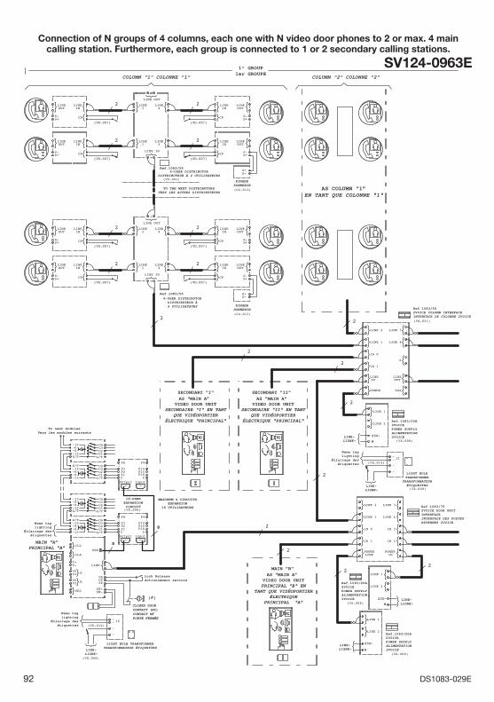
92 DS1083-029E
Connection of N groups of 4 columns, each one with N video door phones to 2 or max. 4 main calling station. Furthermore, each group is connected to 1 or 2 secondary calling stations.
SV124-0963E
Ref.1083/55
Ref.1083/502VOICE COLUMN INTERFACEINTERFACE DE COLONNE 2VOICE
Ref.1083/55
SECONDARY "I" SECONDARY "II"
16-USEREXPANSIONCIRCUIT
MAIN "B"
Ref.1083/752VOICE DOOR UNITINTERFACEINTERFACE DES POSTESEXTERNES 2VOICE
1° GROUP1er GROUPE
COLUMN "1" COLONNE "1" COLUMN "2" COLONNE "2"
AS COLUMN "1”EN TANT QUE COLONNE “1“
4-USER DISTRIBUTORDISTRIBUTEUR À 4 UTILISATEURS
4-USER DISTRIBUTORDISTRIBUTEUR À4 UTILISATEURS
TO THE NEXT DISTRIBUTORSVERS LES AUTRES DISTRIBUTEURS
RINGERSONNERIE
RINGERSONNERIE
To next modulesVers les modules suivants
AS “MAIN A” VIDEO DOOR UNIT
SECONDAIRE “I“ EN TANTQUE VIDÉOPORTIER
ÉLECTRIQUE “PRINCIPAL“
AS “MAIN A” VIDEO DOOR UNIT
SECONDAIRE “II“ EN TANTQUE VIDÉOPORTIER
ÉLECTRIQUE “PRINCIPAL“
MAIN “A”PRINCIPAL “A”
MAXIMUM 4 CIRCUITSEXPANSION
16 UTILISATEURS
Lock ReleaseActionnement serrure
Name taglighting
Éclairage desétiquettes
Name taglighting
Éclairage desétiquettes
CLOSED DOORCONTACT (NC)CONTACT NFPORTE FERMÉE
LINE~LIGNE~
LIGHT BULB TRANSFORMERTRANSFORMATEUR ÉTIQUETTES
AS “MAIN A” VIDEO DOOR UNITPRINCIPAL “B“ EN
TANT QUE VIDÉOPORTIERÉLECTRIQUE
PRINCIPAL “A”
LINE~LIGNE~
230~
230~
N
NLINE~LIGNE~
LINE~LIGNE~
LINE~LIGNE~
Ref.1083/20A2VOICEPOWER SUPPLYALIMENTATION2VOICE
Ref.1083/20A2VOICEPOWER SUPPLYALIMENTATION2VOICE
Name taglighting
Éclairage desétiquettes
LIGHT BULBTRANSFORMER
TRANSFORMATEURÉTIQUETTES
Ref.1083/20A2VOICEPOWER SUPPLYALIMENTATION2VOICE230~
N
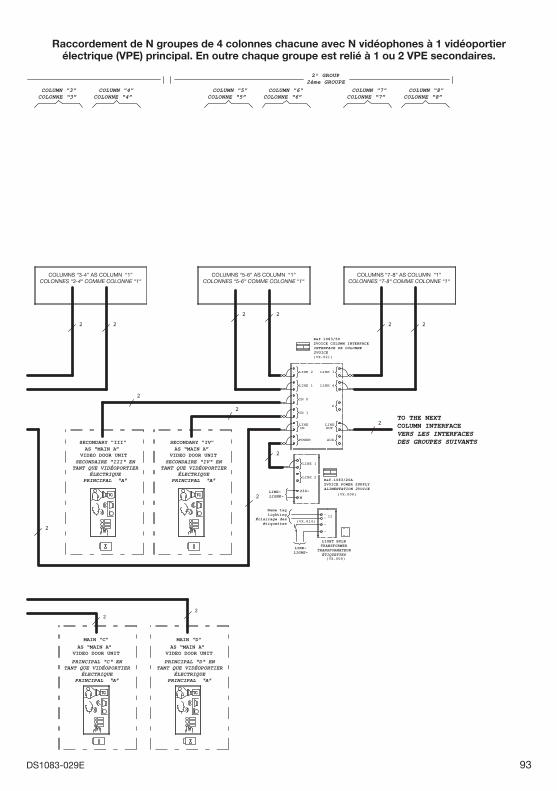
93DS1083-029E
COLUMN "3"COLONNE “3”
COLUMN "4"COLONNE “4”
COLUMN "5"COLONNE “5”
COLUMN "6"COLONNE “6”
COLUMN "7"COLONNE “7”
COLUMN "8"COLONNE “8”
COLUMNS “3-4” AS COLUMN “1”COLONNES “3-4“ COMME COLONNE “1“
COLUMNS “5-6” AS COLUMN “1”COLONNES “5-6“ COMME COLONNE “1“
COLUMNS “7-8” AS COLUMN “1”COLONNES “7-8“ COMME COLONNE “1“
SECONDARY "IV"SECONDARY "III"AS “MAIN A”
VIDEO DOOR UNITAS “MAIN A”
VIDEO DOOR UNIT
AS “MAIN A” VIDEO DOOR UNIT
MAIN "C"AS “MAIN A”
VIDEO DOOR UNIT
MAIN "D"
LINE~LIGNE~
LINE~LIGNE~
230~
N
Ref.1083/20A2VOICE POWER SUPPLYALIMENTATION 2VOICE
Ref.1083/502VOICE COLUMN INTERFACEINTERFACE DE COLONNE2VOICE
TO THE NEXTCOLUMN INTERFACEVERS LES INTERFACESDES GROUPES SUIVANTS
SECONDAIRE “III“ ENTANT QUE VIDÉOPORTIER
ÉLECTRIQUEPRINCIPAL “A”
PRINCIPAL “C“ ENTANT QUE VIDÉOPORTIER
ÉLECTRIQUEPRINCIPAL “A”
PRINCIPAL “D“ ENTANT QUE VIDÉOPORTIER
ÉLECTRIQUEPRINCIPAL “A”
SECONDAIRE “IV“ ENTANT QUE VIDÉOPORTIER
ÉLECTRIQUEPRINCIPAL “A”
LIGHT BULBTRANSFORMER
TRANSFORMATEURÉTIQUETTES
Name taglighting
Éclairage desétiquettes
2° GROUP2ème GROUPE
Raccordement de N groupes de 4 colonnes chacune avec N vidéophones à 1 vidéoportier électrique (VPE) principal. En outre chaque groupe est relié à 1 ou 2 VPE secondaires.
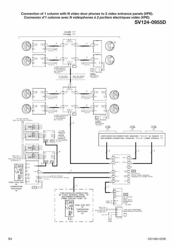
94 DS1083-029E
Connection of 1 column with N video door phones to 2 video entrance panels (VPE).Connexion d’1 colonne avec N vidéophones à 2 portiers électriques vidéo (VPE).
SV124-0955D
2
(VX.006)
2
(VD.007)
2
(VD.007)
2
(VD.007)(VD.007)
22
8
8
(VD.007)
2
(VD.007)
2
2
(VX.037)Ref.1083/55
2
22
(VX.008)
(VX.014)
2
RINGERSONNERIE
(VV.007)
(C4.013)Ref.1072/59
RINGERSONNERIE
COLUMNCOLONNE
“2”
COLUMNCOLONNE
“3”
COLUMNCOLONNE
“4”
(C4.013)Ref.1072/59
A
(VD.007)
2
2
CP S+S-
OUTLINELINE
IN
TC
LINE 1
LINE 2
N
230~
LINELINE
CPS+S-
OUT IN
U2U3
G/T
U4
U1
~12
G/T
~0U1
G/TU3U2
~12~0
U4
~12~0~0~12G/T
CT
V3
SE+
T+
PA
T- LINE
V5
V3 SPV5
SE-SE2
ILL
ILA
A
B
ESP
S-S+
InputOutputC
..
P1P2P3
P8 P9
C
P14P15P16
..
LINE 4
LINE 3
LINE 1
LINE 2
AUX
LINE
IN 0
Z
OUT
POWER
IN 1
LINEIN
LINE1
LINE2
3LINE LINE
4
LINE OUT
LINE IN
LINE1
LINE2
3LINE LINE
4
LINE OUT
LINE IN
U2U3
G/T
U4
U1
~12
G/T
~0U1
G/TU3U2
~12~0
U4
~12~0~0~12G/T
CP S+S-
OUTLINELINE
IN
InputOutputC
..
P1P2P3
P8 P9
C
P14P15P16
..
~~
~
12
~
LINELINE
CPS+S-
OUT IN
S-S+
LINELINE
CPS+S-
OUT IN
LINELINE
CPS+S-
OUT IN LINE
LINE
CP S+S-
TC
COLUMN “1”COLONNE “1”
4-USER DISTRIBUTORDISTRIBUTEUR À 4 UTILISATEURS
Ref.1083/55
4-USER DISTRIBUTORDISTRIBUTEUR À 4 UTILISATEURS
TO THE NEXTDISTRIBUTORS
VERS LES AUTRESDISTRIBUTEURS
To next modulesVers les modules suivants
16-USEREXPANSIONCIRCUITMAXIMUM
4 CIRCUITSEXPANSION
16 UTILISATEURS
Name taglighting
Éclairage desétiquettes
Name taglighting
Éclairage desétiquettes
Lock ReleaseActionnement serrure
VIDEO DOOR UNIT“A”
VIDÉOPORTIERÉLECTRIQUE
“A”
VIDEO DOOR UNIT“B”
VIDÉOPORTIERÉLECTRIQUE
“B”
LIGHT BULB TRANSFORMERTRANSFORMATEUR ÉTIQUETTES
(VX.008)
Ref.1083/20A2VOICEPOWER SUPPLYALIMENTATION2VOICE
LINE~LIGNE~
LINE~LIGNE~
Ref.1083/502VOICE COLUMN INTERFACEINTERFACE DE COLONNE 2VOICE
CONFIGURATION/CONNECTIONS BRANCHES “2-3-4” AS BRANCH “1”ÉQUIPEMENT/CONNEXIONS DORSALES “2-3-4” COMME DORSALE “1”
CONFIGURATION/CONNECTIONSAS VIDEO ENTRANCE PANEL “A”
ÉQUIPEMENT/CONNEXIONS COMME PORTIER VIDÉO “A”
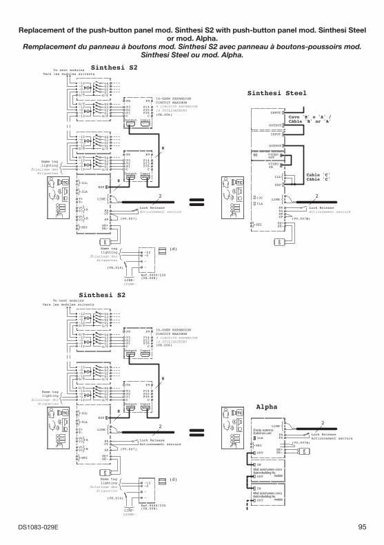
95DS1083-029E
Replacement of the push-button panel mod. Sinthesi S2 with push-button panel mod. Sinthesi Steel or mod. Alpha.
Remplacement du panneau à boutons mod. Sinthesi S2 avec panneau à boutons-poussoirs mod. Sinthesi Steel ou mod. Alpha.
Sinthesi S2
=8
8
(VV.007)
2
Sinthesi S2
Ref.9000/230(VX.008)
(VX.014)
(d)
=8
8
(VX.006)
(VV.007)
Sinthesi Steel
Cavo 'B' o 'A' / Câble 'B' or 'A'
Cable 'C'Câble 'C'
(VV.007B)
22
(VX.006)
Ref.9000/230(VX.008)
(VX.014)
(d)
Alpha
(VV.007A)
2
InputOutputC
..
P1P2P3
P8 P9
C
P14P15P16
..
InputOutputC
..
P1P2P3
P8 P9
C
P14P15P16
..
TC
U2U3
G/T
U4
U1
~12
G/T
~0U1
G/TU3U2
~12~0
U4
~12~0~0~12G/T
SE+SE-
LINE
PAPA
SE2
OUT
Posto esternoExternal unitILA
InputOutputC
..
P1P2P3
P8 P9
C
P14P15P16
..
TC
OUT
IN
Mod. tasti/numero civicoButton/building No.
module
~0~12
~
~
TC
U2U3
G/T
U4
U1
~12
G/T
~0U1
G/TU3U2
~12~0
U4
~12~0~0~12G/T
CTV3
SE+
T+
PA
T-LINE
V5
V3 SPV5
SE-SE2
ILL
ILA
A
B
ESP
~0~12
~
~
U2U3
G/T
U4
U1
~12
G/T
~0U1
G/TU3U2
~12~0
U4
~12~0~0~12G/T
CTV3
SE+
T+
PA
T-LINE
V5
V3 SPV5
SE-SE2
ILL
ILA
A
B
ESP
SP
SE+
PA
LINE
SP
SE-SE2
ILL
ILA
EXP
OUTPUT
INPUT
INPUT
OUTPUT
PA
I2C
VIDEOOUT
TC
INVIDEO
TC
OUT
IN
Mod. tasti/numero civicoButton/building No.
module
InputOutputC
..
P1P2P3
P8 P9
C
P14P15P16
..
U2U3
G/T
U4
U1
~12
G/T
~0U1
G/TU3U2
~12~0
U4
~12~0~0~12G/T
To next modulesVers les modules suivants
Name taglighting
Éclairage desétiquettes
Name taglighting
Éclairage desétiquettes
Name taglighting
Éclairage desétiquettes
Name taglighting
Éclairage desétiquettes
16-USER EXPANSIONCIRCUIT MAXIMUM 4 CIRCUITS EXPANSION16 UTILISATEURS
LINE~LIGNE~
LINE~LIGNE~
Lock ReleaseActionnement serrure
Lock ReleaseActionnement serrure
Lock ReleaseActionnement serrure
Lock ReleaseActionnement serrure
To next modulesVers les modules suivants
16-USER EXPANSIONCIRCUIT MAXIMUM 4 CIRCUITS EXPANSION16 UTILISATEURS
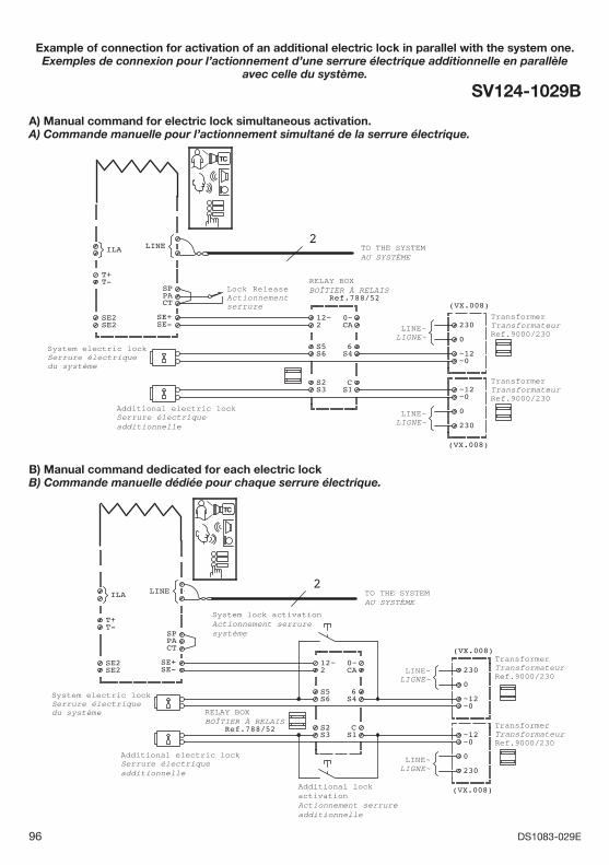
96 DS1083-029E
Example of connection for activation of an additional electric lock in parallel with the system one.Exemples de connexion pour l’actionnement d’une serrure électrique additionnelle en parallèle
avec celle du système.
SV124-1029B
(VX.008)
(VX.008)
2
230
0
~0~12
PA
SE2SE-SE2SE+
SP
CT
LINEILA
T+T-
~0
230
~12
0
S5S6 S4
6
S2 CS1S3
0~12~CA2
TC
Lock ReleaseActionnementserrure
LINE~LIGNE~
LINE~LIGNE~
TO THE SYSTEMAU SYSTÈME
Ref.788/52
RELAY BOXBOÎTIER À RELAIS
System electric lockSerrure électriquedu système
Additional electric lockSerrure électriqueadditionnelle
TransformerTransformateurRef.9000/230
TransformerTransformateurRef.9000/230
(VX.008)
(VX.008)
2
Ref.788/52
TC
230
0
~0~12
~0
230
~12
0
S5S6 S4
6
S2 CS1S3
0~12~CA2
PA
SE2SE-SE2SE+
SP
CT
LINEILA
T+T-
LINE~LIGNE~
LINE~LIGNE~
TO THE SYSTEMAU SYSTÈME
RELAY BOXBOÎTIER À RELAIS
System electric lockSerrure électriquedu système
Additional electric lockSerrure électriqueadditionnelle
System lock activationActionnement serrure système
TransformerTransformateurRef.9000/230
TransformerTransformateurRef.9000/230
Additional lock activationActionnement serrure additionnelle
A) Manual command for electric lock simultaneous activation.A) Commande manuelle pour l’actionnement simultané de la serrure électrique.
B) Manual command dedicated for each electric lockB) Commande manuelle dédiée pour chaque serrure électrique.
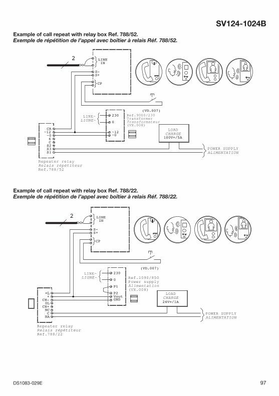
97DS1083-029E
SV124-1024B
POWER SUPPLY ALIMENTATION
LINE~LIGNE~
Ref.9000/230TransformerTransformateur(VX.008)
LOADCHARGE
Repeater relayRelais répétiteurRef.788/52
(VD.007)
2
100V=/5A
LINEIN
CP
S-S+
S2
CA
S3
C
~0
S1
6
~12
0
230
~12~0
Example of call repeat with relay box Ref. 788/52.Exemple de répétition de l’appel avec boîtier à relais Réf. 788/52.
POWER SUPPLY ALIMENTATION
LINE~LIGNE~ Ref.1090/850
Power supplyAlimentation(VX.008)
LOADCHARGE
Repeater relayRelais répétiteurRef.788/22
24V=/1A
2
(VD.007)
LINEIN
CP
S-S+
0
GND
P1
VoutP2
230
+L
0L
CNC
CH-+
NA
CH+
Example of call repeat with relay box Ref. 788/22.Exemple de répétition de l’appel avec boîtier à relais Réf. 788/22.
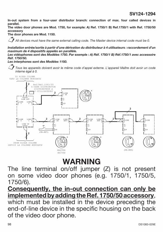
98 DS1083-029E
SV124-1294In-out system from a four-user distributor branch: connection of max. four called devices in parallel.The video door phones are Mod. 1750, for example: A) Ref. 1750/1 B) Ref.1750/1 with Ref. 1750/50 accessoryThe door phones are Mod. 1150.
All devices must have the same external calling code. The Master device internal code must be 0.
Installation entrée/sortie à partir d’une dérivation du distributeur à 4 utilisateurs : raccordement d’un maximum de 4 dispositifs appelés en parallèle. Les vidéophones sont des Modèles 1750. Par exemple : A) Réf. 1750/1 B) Réf.1750/1 avec accessoire Réf. 1750/50.Les interphones sont des Modèles 1150.
Tous les appareils doivent avoir le même code d’appel externe. L’appareil Maître doit avoir un code interne égal à 0.
§
§
(VD.007)
2
2
2
2 2
2
(V2.003)
2LINE4
LINE1
3LINE LINE
2
LINE OUT
LINE IN
B
OUTLINELINE
IN
CP
S-S+
B
LINEIN
CP
S-S+
A
OUTLINELINE
IN
CP
S-S+
CP
S-S+
LINE
CP
S-S+
LINE
Ref/Réf.1083/554-USER DISTRIBUTOR
DISTRIBUTEUR A4 UTILISATEURS
TO RISER COLUMNVERS LA COLONNE MONTANTE
FROM RISER COLUMNDEPUIS LA COLONNE MONTANTE
MASTERMAÎTRE
WARNINGThe line terminal on/off jumper (Z) is not present on some video door phones (e.g. 1750/1, 1750/5, 1750/6).Consequently, the in-out connection can only be implemented by adding the Ref. 1750/50 accessory, which must be installed in the device preceding the end-of-line device in the specifi c housing on the back of the video door phone.
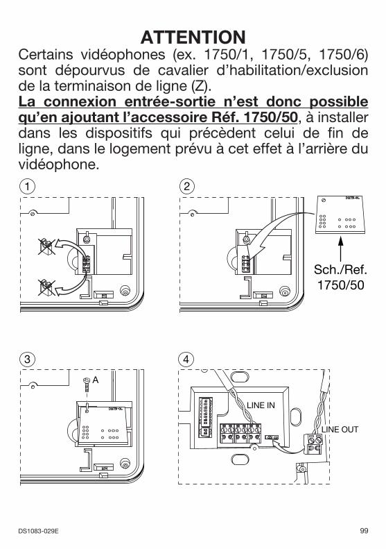
99DS1083-029E
ATTENTIONCertains vidéophones (ex. 1750/1, 1750/5, 1750/6) sont dépourvus de cavalier d’habilitation/exclusion de la terminaison de ligne (Z).La connexion entrée-sortie n’est donc possible qu’en ajoutant l’accessoire Réf. 1750/50, à installer dans les dispositifs qui précèdent celui de fi n de ligne, dans le logement prévu à cet effet à l’arrière du vidéophone.1 2
3
A
4
LINE IN
LINE OUT
Sch./Ref.1750/50
DS 1083-029E LBT 8629
Area tecnicaservizio clienti +39 011.23.39.810http://www.urmet.come-mail: [email protected]
MADE IN CHINA
URMET S.p.A.10154 TORINO (ITALY)VIA BOLOGNA 188/CTelef. +39 011.24.00.000 (RIC. AUT.)Fax +39 011.24.00.300 - 323
The symbol of the crossed-out wheeled bin on the product or on its packaging indicates that this product must not be disposed of with your other household waste. Instead, it is your responsibility to dispose of your waste equipment by handing it over to a designated collection point for the recycling of waste electrical and electronic equipment. The separate collection and recycling of your waste equipment at the time of disposal will help to conserve natural resources and ensure that it is recycled in a manner that protects human health and the environment.For more information about where you can drop off your waste equipment for recycling, please contact your local city offi ce, your household waste disposal service or the shop where you purchased the product.
DIRECTIVE 2012/19/EU OF THE EUROPEAN PARLIAMENT AND OF THE COUNCIL of 4 July 2012 on waste electrical and electronic equipment (WEEE)
ENGLISH
Le symbole de la poubelle sur roues barrée d’une croix présent sur le produit ou sur son emballage indique que ce produit ne doit pas être éliminé avec vos autres déchets ménagers. Au lieu de cela, il est de votre responsabilité de vous débarrasser de vos équipements usagés en les remettant à un point de collecte spécialisé pour le recyclage des déchets des équipements électriques et électroniques (DEEE). La collecte et le recyclage séparés de vos équipements usagés au moment de leur mise au rebut aidera à conserver les ressources naturelles et à assurer qu’elles sont recyclées d’une manière qui protège la santé humaine et l’environnement. Pour plus d’informations sur les lieux de collecte où vous pouvez déposer vos équipements usagés pour le recyclage, veuillez contacter votre revendeur, votre service local d’élimination des ordures ménagères.
DIRECTIVE EUROPEENNE 2012/19/UE du 4 juillet 2012 relatif aux déchets d’équipements électriques et électroniques (DEEE)
FRANÇAIS