Embed Size (px)
Citation preview

IP-POE24M Hardware Installation Manual

Table of Contents
- I -
Table of Contents
Chapter 1 IP-POE24M Switch .............................................................................................................................................. 1
1.1 Standard Configuration ......................................................................................................................................... 1
1.2 Characteristic Parameters of IP-POE24M ............................................................................................................. 3
1.3 ROHS Description ................................................................................................................................................. 4
Chapter 2 Installation Preparation ........................................................................................................................................ 5
2.1 Cautions ................................................................................................................................................................ 5
2.2 Safety Advice ......................................................................................................................................................... 5
2.2.1 Safety Principles ....................................................................................................................................... 5
2.2.2 Safety Notices ........................................................................................................................................... 5
2.2.3 Safety Principles for Live Working ............................................................................................................. 6
2.2.4 Electrostatic Discharge Prevention ........................................................................................................... 6
2.3 Requirements for Common Locations ................................................................................................................... 7
2.3.1 Environment .............................................................................................................................................. 7
2.3.2 Location Configuration Prevention ............................................................................................................ 7
2.3.3 Cabinet Configuration ............................................................................................................................... 7
2.3.4 Power Requirements ................................................................................................................................. 8
2.4 Installation Tools and Device ................................................................................................................................. 8
Chapter 3 Installing the IP-POE24M Switch ......................................................................................................................... 9
3.1 Installation Flow of IP-POE24M ............................................................................................................................ 9
3.2 Installing the Chassis of the Switch ....................................................................................................................... 9
3.2.1 Installing the Machine Box on the Desk .................................................................................................. 10
3.2.2 Installing the Chassis on the Cabinet ...................................................................................................... 10
3.3 Connecting the Port ............................................................................................................................................. 10
3.3.1 Connecting the Console Port .................................................................................................................. 10
3.3.2 Connecting Fast-Ethernet Interface ........................................................................................................ 12
3.3.3 Connecting the 1000M Ethernet Port ...................................................................................................... 14
3.4 Checking After Installation ................................................................................................................................... 16
Chapter 4 Maintaining the Switch ....................................................................................................................................... 17
4.1 Opening the Chassis ........................................................................................................................................... 17
4.2 Closing Chassis ................................................................................................................................................... 18
Chapter 5 Hardware Fault Analysis .................................................................................................................................... 19
5.1 Fault Separation .................................................................................................................................................. 19
5.1.1 Faults Relative with Power and Cooling System ..................................................................................... 19
5.1.2 Faults Relative with Port, Cable and Connection .................................................................................... 19
5.2 Indicator Description ............................................................................................................................................ 19
IP-POE24M Hardware Installation Manual
- 1 -
Chapter 1 IP-POE24M Switch
This document describes the characteristics and parameters of the IP-POE24M and gives an overview of IP-POE24M physical interfaces.
1.1 Standard Configuration
The accessory ports of the IP-POE24M is composed of 24 fast-Ethernet ports, four 1000M optical/electrical ports and one console port. See table 1-1.
Table 1-1 Attributes of the necessary port
Port Attribute
fast-Ethernet POE port
An port, which has a 10/100M auto-adaptation,
MDI/MDIX auto-identification for cable,
UTP(RJ45) port and the LINK/ACT 100Mbps
indicators. Each fast-Ethernet port has the POE
function. Each port can provide the outside up to
30W power consumption and the total power
consumption reaches 400W.
1000M optical/electrical port
Electrical port: 10/100/1000M auto-adaptation,
MDI/MDIX auto-identification of cable, UTP(RJ45)
port and the LINK/ACT indicators
SFP port: having LINK/ACT indicators
Console port An RJ45 port with a rate of 9600 bps
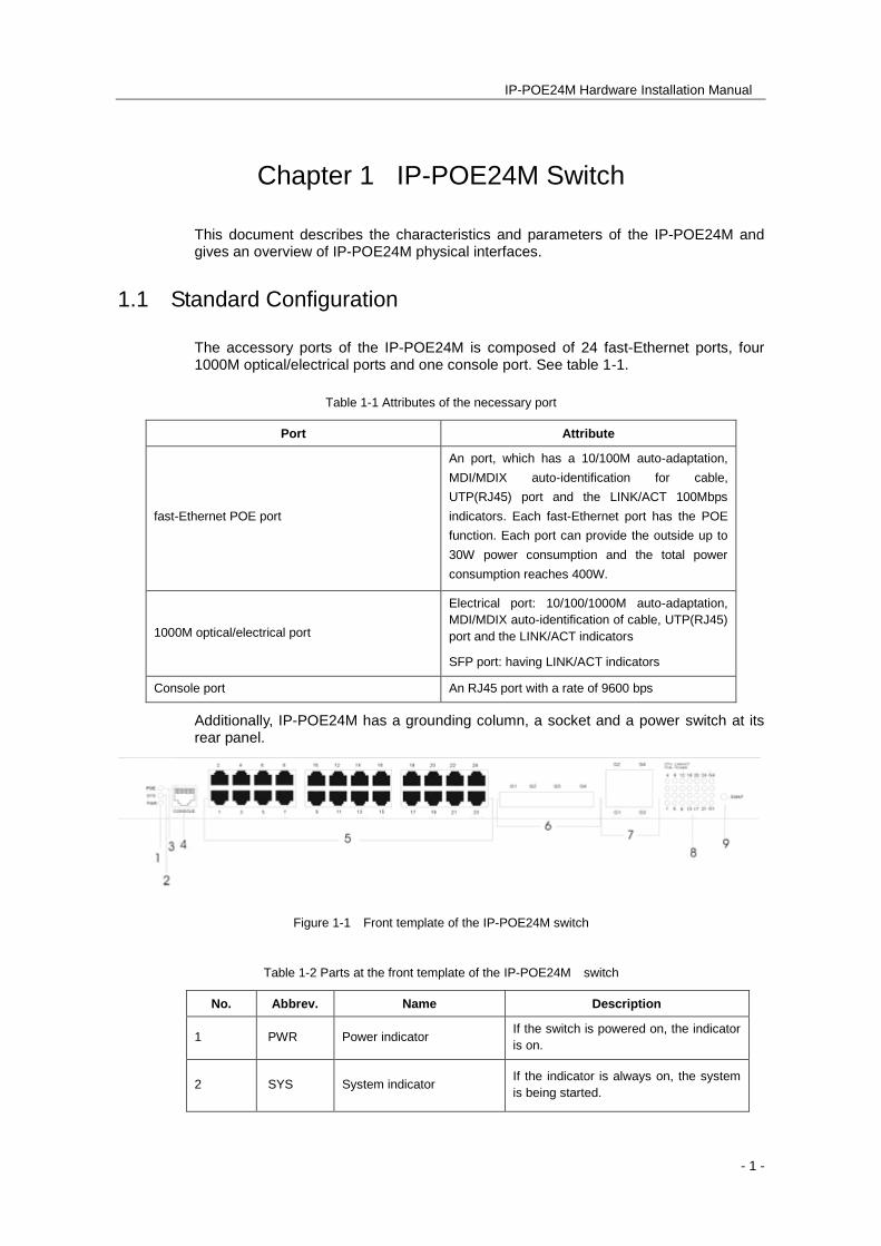
Additionally, IP-POE24M has a grounding column, a socket and a power switch at its rear panel.
Figure 1-1 Front template of the IP-POE24M switch
Table 1-2 Parts at the front template of the IP-POE24M switch
No. Abbrev. Name Description
1 PWR Power indicator If the switch is powered on, the indicator
is on.
2 SYS System indicator If the indicator is always on, the system
is being started.
IP-POE24M Hardware Installation Manual
- 2 -
If the indicator flickers, the system works
normally.
3 POE POE指示灯POE indicator
If the POE indicator is on, it means that
24 indicators on the right side show the
state of the POE port.
4 CONSOLE Console port Manages the switch locally.
5 1-24 24 electrical port with the
POE function
Forward the 10/100M Ethernet electrical
signals and provide POE function.
Their peers can be connected to the PD
devices which satisfy the IEEE 802.3af
standard.
6 G1-G4 Gigabit-Ethernet optical
port
Forwards the 1000M Ethernet optical
signals.
7 G1-G4 Gigabit-Ethernet electrical
port
Forwards the 10/100/1000M Ethernet
electrical signals.
8 LINK/ACT
Normal mode of the
indicator: indicating the
LINK/ACT state of each
port
POE mode of the indicator:
indicating the POE power
supply state of each port
Normal mode:
If the indicator is always on, the link on
the port is normal.
If the indicator flickers, the data is
received or transmitted through the port.
POE mode:
If the indicator is always on, the port is
powered through the POE mode.
If the indicator is off, the port is not
supplied with power.
9 SWAP
A shift key for exchanging
the normal mode with the
POE mode of the indicator
If you press the shift key in normal
mode, the indicator will enter the POE
mode. If you press again, the indicator
will enter the normal mode again.
If you leave the key alone for 30
seconds in POE mode, the indicator
automatically enters the normal mode.
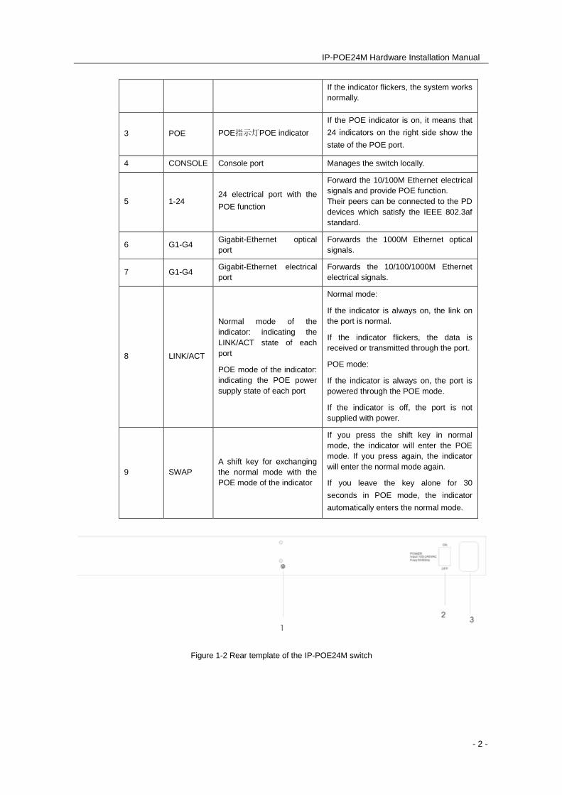
Figure 1-2 Rear template of the IP-POE24M switch
IP-POE24M Hardware Installation Manual
- 3 -
Table 1-3 Parts at the rear template of the IP-POE24M switch
No. Abbrev. Name Description
1 None Grounding
column Properly ground the system.
2 None
Power switch ON means activating power, while
OFF means disabling power.
3 None AC power socket AC100-240V
1.2 Characteristic Parameters of IP-POE24M
Protocol standard
IEEE 802.1d Spanning Tree Protocol
IEEE 802.1p Class of Service
IEEE 802.1q tagged VLAN
IEEE 802.3x Flow control
IEEE 802.3ad Link aggregation
IEEE 802.3af standard
Network management
standard
RFC 1157 SNMP v1/v2
RFC 1213 MIB II
RFC 1757 RMON 1,2,3,9
Memory EPROM: 512k Bytes
Flash Memory: 8M Bytes
SDRAM: 64Mbytes
Standard configuration 24 10/100Base-TX ports
One Console port
Four fixed 1000M optical/electrical Ethernet ports
Specifications 442.50*315.00*44mm
Working
temperature/humidity
0℃-60℃; 10%-85% no condensation
Storage temperature/
humidity
-40℃-80℃; 5%-95% no condensation
AC power supply Input voltage: AC100-240V
Input frequency: 47-63Hz
Input current: 5A/230V
Power consumption Up to 400W
IP-POE24M Hardware Installation Manual
- 4 -
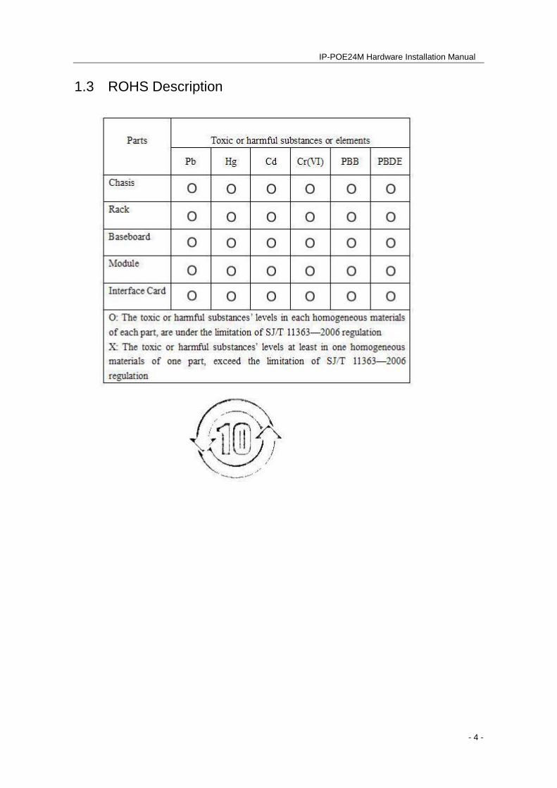
1.3 ROHS Description
IP-POE24M Hardware Installation Manual
- 5 -
Chapter 2 Installation Preparation
2.1 Cautions
Similar to other electronic products, the semiconductor chip easily gets damaged if you power on and off abruptly and frequently. To restart the IP-POE24M, you have to toggle the power switch three or five seconds after the power is turned off.
Avoid severe collision or drops to the PoE switch.
Use correct outside ports to connect to the IP-POE24M. Do not insert the Ethernet plug into the console port (RJ45 8-line socket). Similarly, do not insert the console cable into the console port (RJ45 8-line socket).
Note:
1) When you insert or remove the power cable, keep the power line horizontal with the power socket.
2) When the lifetime of our products ends, handle them according to national laws and regulations, or send these products to our company for collective processing.
3) Caution: It is not recommended to connect the POE ports of two POE devices directly.
2.2 Safety Advice
2.2.1 Safety Principles
Keep dustless and clean during and after the installation.
Place the switch in a safe location.
Put tools at the right place where they are not easily dropped.
Put on relatively tight clothes, fasten ties or scarves well and roll up sleeves to avoiding snagging on the chassis.
Use protective glasses if the environment may cause damage to your eyes.
Avoid incorrect operations that may cause damage to devices or injuries.
2.2.2 Safety Notices
Read the installation guide carefully before you operate the system.
Only professionals are allowed to install or replace the switch.
IP-POE24M Hardware Installation Manual
- 6 -
Pull out the AC power socket and close the direct-current power before operating on the chassis or working beside the power source.
The final configuration of the switch must comply with relative national laws and regulations.
2.2.3 Safety Principles for working on a live switch
When working with live equipment, please follow these principles:
Remove ornaments, such as rings, necklaces, watches and bracelets, before you operate on the switch. When metal articles connect the power to the ground, short circuit happens and components may be damaged.
Pull out the AC power socket and close the direct-current power before operating on the chassis or working beside the power source.
When the power is on, do not touch the power.
Correctly connect the device and the power socket.
Only professionals are allowed to operate and maintain the device.
Read the installation guide carefully before the system is powered on.
Note:
Check potential dangers, such as the humidity, ungrounded extension power cords and frayed power lines.
Turn off the switch and remove the power line before installing or uninstalling the chassis or working beside the power.
Do not work alone if potential dangers exist.
Cut off the power before troubleshooting.
If trouble happens, take the following measures:
A. Cut off the system’s power.
B. Notify appropriate personnel.
C. Take proper measures to help persons who are injured
D. Seek medical help.
2.2.4 Electrostatic Discharge Prevention
Electrostatic discharge may damage devices and circuits. Improper treatment may cause the switch to malfunction completely or discontinuously.
Move or locate the devices according to the measures of electrostatic discharge prevention, ensuring the chassis connects the ground. Another measure is to wear a
IP-POE24M Hardware Installation Manual
- 7 -
static-proof hand ring. If there is no hand ring, use the metal clip with the metal cable to clip the unpainted metal part of the chassis. In this case, the static is discharged to the ground through the metal cable of the clip. You can also discharge the static to the ground through your body.
2.3 Requirements for Common Locations
This section describes the requirements for installation locations.
2.3.1 Environment
The switch can be installed on a desk or an equipment cabinet. The location of the chassis, cabinet planning and indoor cabling are very important for normal system function. Short distances between devices, bad ventilation and an untouchable control plate will cause maintenance problems, systematic fault and breakdown.
For location planning and device locating, refer to section 2.3.2 “Location Configuration Prevention”.
2.3.2 Location Configuration Prevention
The following preventive measures assist you to design the proper environment for the switch.
Make sure that the workshop is well-ventilated, the heat of electrical devices is well-discharged and sufficient air circulation is provided for device cooling.
Avoid damage to devices by following electrostatic discharge prevention procedures.
Put the chassis in a place where cool air can blow off the heat inside the chassis. Make sure the chassis is sealed because the opened chassis will reverse the cool air flow.
2.3.3 Cabinet Configuration
The following content describes a proper cabinet configuration:
Each device on the cabinet gives off heat when it runs. Therefore, the sealed cabinet must have a heat-discharge outlet and the cooling fan. Do not put the devices too close, avoiding bad ventilation.
When you install the chassis in an open cabinet, prevent the frame of the cabinet from blocking the airway of the chassis.
Ensure that proper ventilation is provided for the devices installed in the bottom of the cabinet.
The clapboard separates exhaust gas and inflow air, and boost the cool air to flow in the chassis. The best location of the clapboard is decided by the
IP-POE24M Hardware Installation Manual
- 8 -
air flow mode in the chassis, which can be obtained through different location tests.
2.3.4 Power Requirements
Make sure that the power supply has proper grounding and the power at the input side of the switch is reliable. The voltage control can be installed if necessary. At least a 240 V, 10A fuse or a breaker is provided in the phase line if you prepare the short-circuit prevention measures for a building.
Caution:
If the power supply system does not have good grounding, or the input power disturbs too much and excessive pulses exist, the error code rate of communication devices could increase, and potentially cause hardware failure.
2.4 Installation Tools and Device
The tools and devices to install the IP-POE24M switch are not provided by the IP-POE24M switch. You yourself need to prepare them. The following are the tools and devices needed for the typical installation of the IP-POE24M switch:
Screwdriver
Static armguard
Bolt
Ethernet cable
Other Ethernet terminal devices
Control terminal
IP-POE24M Hardware Installation Manual
- 9 -
Chapter 3 Installing the IP-POE24M Switch
Caution:
Only professionals are allowed to install or replace the IP-POE24M.
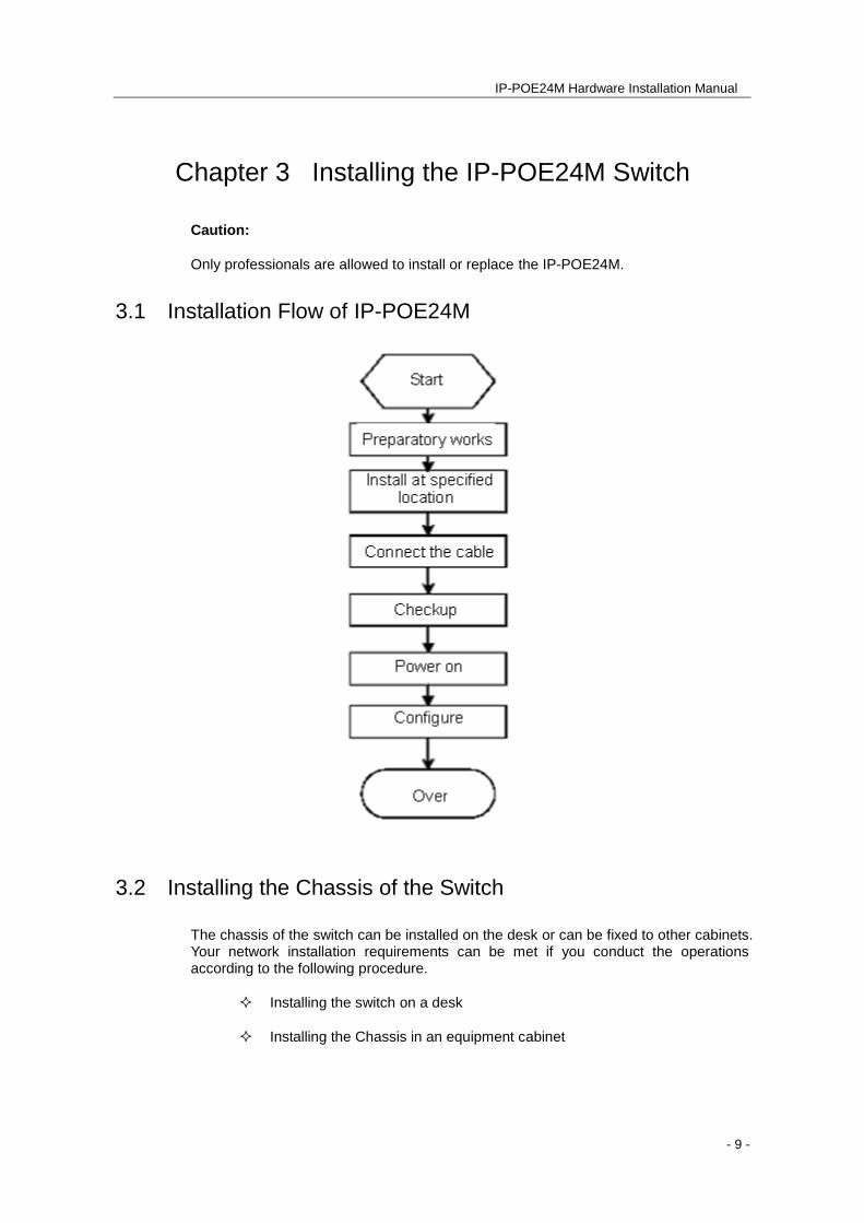
3.1 Installation Flow of IP-POE24M
3.2 Installing the Chassis of the Switch
The chassis of the switch can be installed on the desk or can be fixed to other cabinets. Your network installation requirements can be met if you conduct the operations according to the following procedure.
Installing the switch on a desk
Installing the Chassis in an equipment cabinet
IP-POE24M Hardware Installation Manual
- 10 -
3.2.1 Installing the Machine Box on the Desk
The IP-POE24M switch can be directly put on smooth and safe desk.
Note:
Do not put things weighing 4.5 kg or over 4.5 kg on top of the switch.
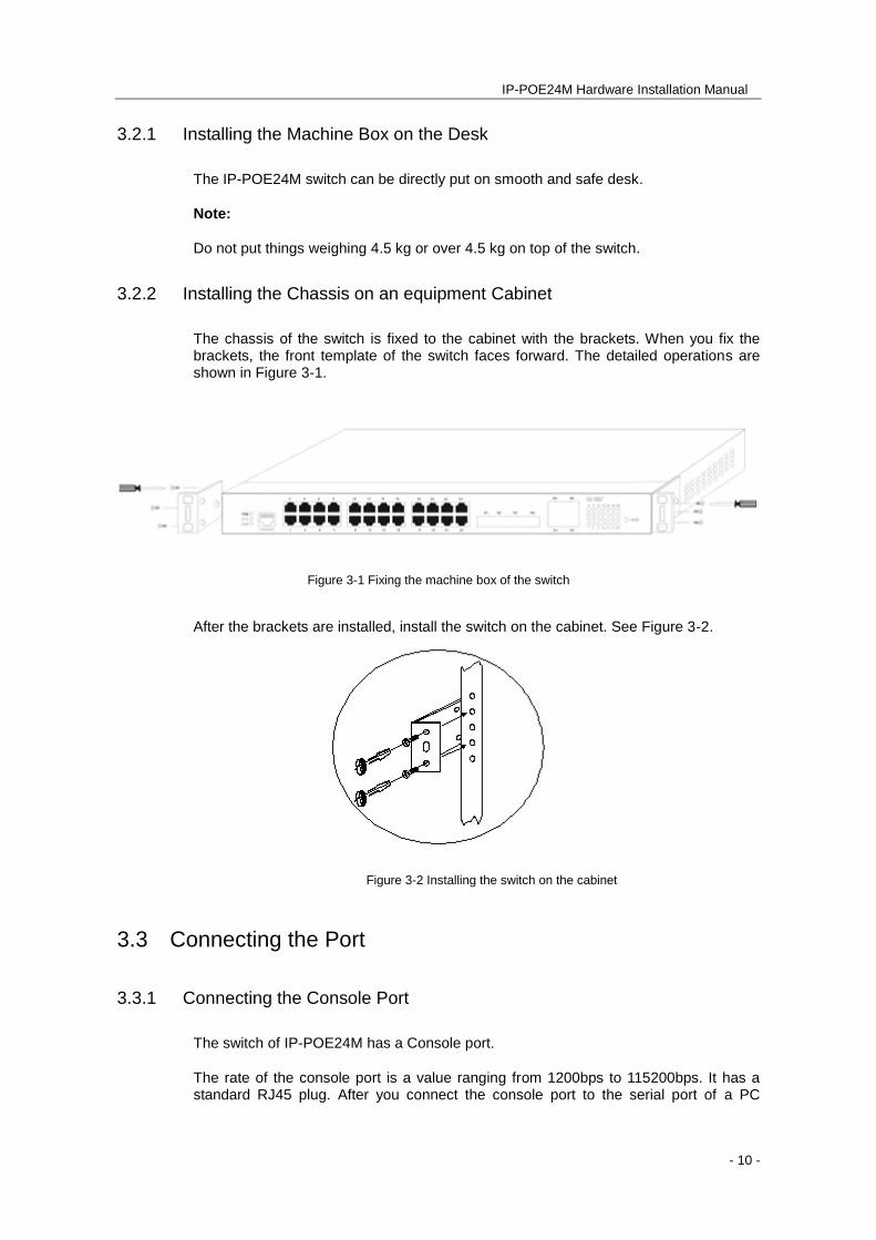
3.2.2 Installing the Chassis on an equipment Cabinet
The chassis of the switch is fixed to the cabinet with the brackets. When you fix the brackets, the front template of the switch faces forward. The detailed operations are shown in Figure 3-1.
Figure 3-1 Fixing the machine box of the switch
After the brackets are installed, install the switch on the cabinet. See Figure 3-2.
Figure 3-2 Installing the switch on the cabinet
3.3 Connecting the Port
3.3.1 Connecting the Console Port
The switch of IP-POE24M has a Console port.
The rate of the console port is a value ranging from 1200bps to 115200bps. It has a standard RJ45 plug. After you connect the console port to the serial port of a PC
IP-POE24M Hardware Installation Manual
- 11 -
through a console cable, you can configure and monitor the switch of IP-POE24M by running a terminal emulation software, such as super Windows terminal. The cable is provided according to the host. The communication parameters of the terminal serial port can be set to a rate of 9600bps, eight data bits, one stop bit, no sum check bit and traffic control.
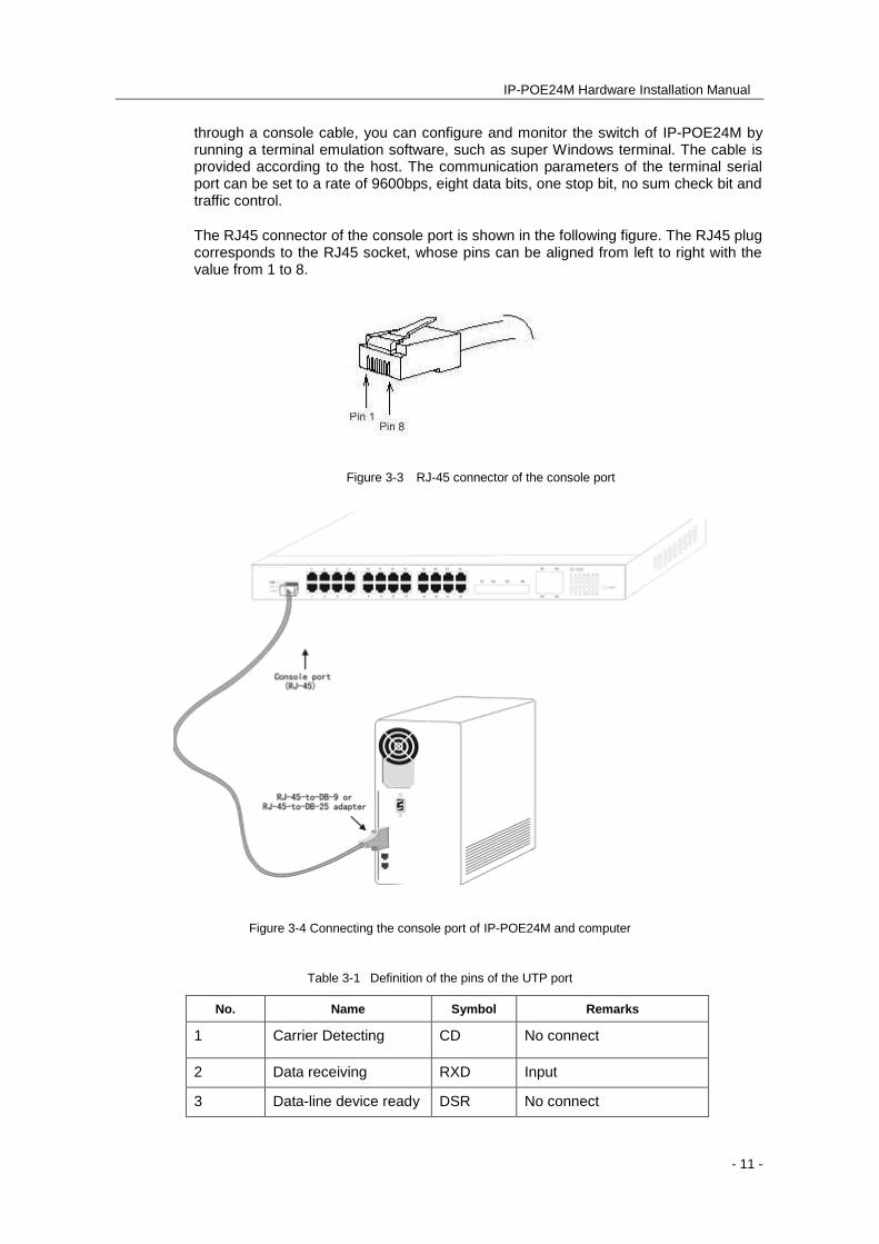
The RJ45 connector of the console port is shown in the following figure. The RJ45 plug corresponds to the RJ45 socket, whose pins can be aligned from left to right with the value from 1 to 8.
Figure 3-3 RJ-45 connector of the console port
Figure 3-4 Connecting the console port of IP-POE24M and computer
Table 3-1 Definition of the pins of the UTP port
No. Name Symbol Remarks
1 Carrier Detecting CD No connect
2 Data receiving RXD Input
3 Data-line device ready DSR No connect
IP-POE24M Hardware Installation Manual
- 12 -
4 Data transmitting TXD Output
5 Transmission
requesting
RTS No connect
6 Response transmitting CTS No connect
7 Data terminal ready DTR No connect
8 Signal ground SG GND
Note:
The console port of the IP-POE24M switch does not support traffic control. Therefore, you must set the option data traffic control to none when you configure the switch
with the super terminal.
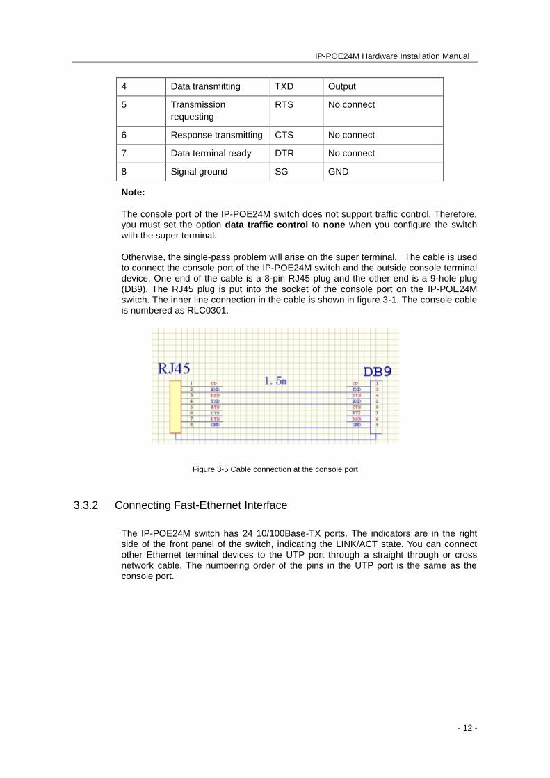
Otherwise, the single-pass problem will arise on the super terminal. The cable is used to connect the console port of the IP-POE24M switch and the outside console terminal device. One end of the cable is a 8-pin RJ45 plug and the other end is a 9-hole plug (DB9). The RJ45 plug is put into the socket of the console port on the IP-POE24M switch. The inner line connection in the cable is shown in figure 3-1. The console cable is numbered as RLC0301.
Figure 3-5 Cable connection at the console port
3.3.2 Connecting Fast-Ethernet Interface
The IP-POE24M switch has 24 10/100Base-TX ports. The indicators are in the right side of the front panel of the switch, indicating the LINK/ACT state. You can connect other Ethernet terminal devices to the UTP port through a straight through or cross network cable. The numbering order of the pins in the UTP port is the same as the console port.
IP-POE24M Hardware Installation Manual
- 13 -
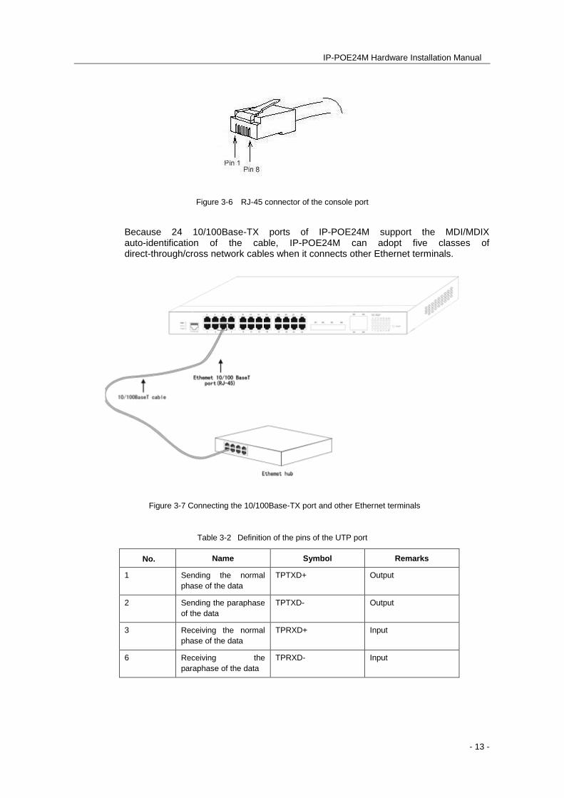
Figure 3-6 RJ-45 connector of the console port
Because 24 10/100Base-TX ports of IP-POE24M support the MDI/MDIX auto-identification of the cable, IP-POE24M can adopt five classes of direct-through/cross network cables when it connects other Ethernet terminals.
Figure 3-7 Connecting the 10/100Base-TX port and other Ethernet terminals
Table 3-2 Definition of the pins of the UTP port
No. Name Symbol Remarks
1 Sending the normal
phase of the data
TPTXD+ Output
2 Sending the paraphase
of the data
TPTXD- Output
3 Receiving the normal
phase of the data
TPRXD+ Input
6 Receiving the
paraphase of the data
TPRXD- Input
IP-POE24M Hardware Installation Manual
- 14 -
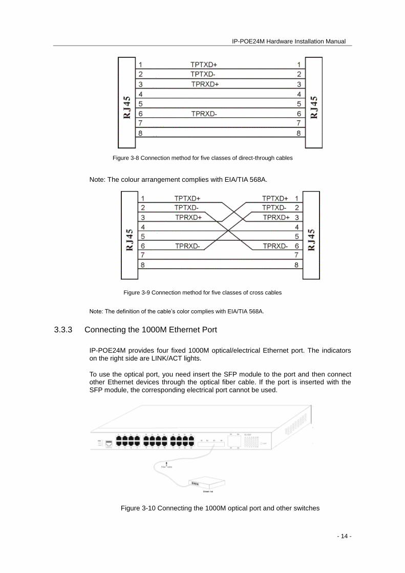
Figure 3-8 Connection method for five classes of direct-through cables
Note: The colour arrangement complies with EIA/TIA 568A.
Figure 3-9 Connection method for five classes of cross cables
Note: The definition of the cable’s color complies with EIA/TIA 568A.
3.3.3 Connecting the 1000M Ethernet Port
IP-POE24M provides four fixed 1000M optical/electrical Ethernet port. The indicators on the right side are LINK/ACT lights.
To use the optical port, you need insert the SFP module to the port and then connect other Ethernet devices through the optical fiber cable. If the port is inserted with the SFP module, the corresponding electrical port cannot be used.
Figure 3-10 Connecting the 1000M optical port and other switches
IP-POE24M Hardware Installation Manual
- 15 -
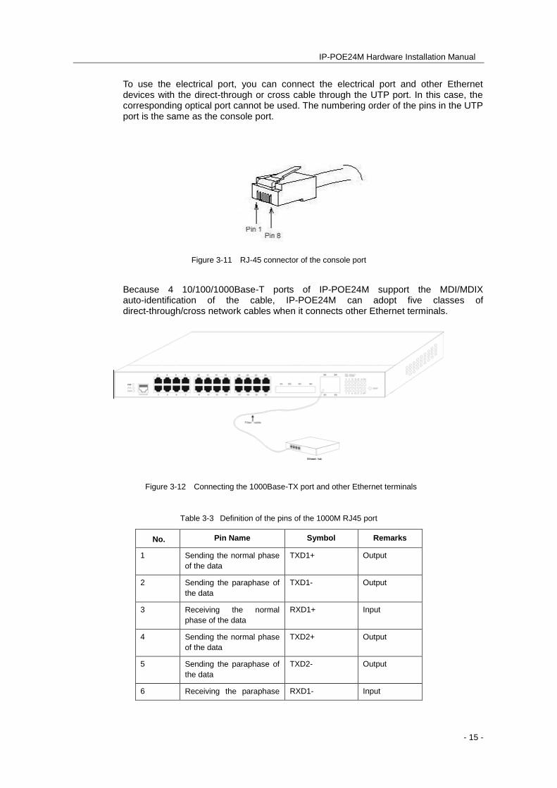
To use the electrical port, you can connect the electrical port and other Ethernet devices with the direct-through or cross cable through the UTP port. In this case, the corresponding optical port cannot be used. The numbering order of the pins in the UTP port is the same as the console port.
Figure 3-11 RJ-45 connector of the console port
Because 4 10/100/1000Base-T ports of IP-POE24M support the MDI/MDIX auto-identification of the cable, IP-POE24M can adopt five classes of direct-through/cross network cables when it connects other Ethernet terminals.
Figure 3-12 Connecting the 1000Base-TX port and other Ethernet terminals
Table 3-3 Definition of the pins of the 1000M RJ45 port
No. Pin Name Symbol Remarks
1 Sending the normal phase
of the data
TXD1+ Output
2 Sending the paraphase of
the data
TXD1- Output
3 Receiving the normal
phase of the data
RXD1+ Input
4 Sending the normal phase
of the data
TXD2+ Output
5 Sending the paraphase of
the data
TXD2- Output
6 Receiving the paraphase RXD1- Input
IP-POE24M Hardware Installation Manual
- 16 -
of the data
7 Receiving the normal
phase of the data
RXD2+ Input
8 Receiving the paraphase
of the data
RXD1- Input
The direct-through or cross network cable has the function of auto-identification, so the five classes of direct-through/cross network cables can be used to connect other Ethernet devices.
3.4 Checking After Installation
Before starting up the switch, perform the following checks after the switch is installed:
If the switch is installed on a cabinet, check whether the installation point between the cabinet and the switch is strong. If the switch is installed on a desk, check whether there is enough space for the switch to discharge its heat and whether the desk is stable.
Check whether the connected power meets the power requirements of the switch.
Check whether the grounding line is correctly connected.
Check whether the switch is correctly connected to other terminal devices.
IP-POE24M Hardware Installation Manual
- 17 -
Chapter 4 Maintaining the Switch
Caution:
Before opening the chassis, make sure that you have released the static you carried and then toggle the power of the switch. Before operating any step in Appendix B, read the section “Safety Advice”.
Before performing operations beside the power source or on the chassis, turn off the power switch and remove the power cable.
4.1 Opening the Chassis
This section describes how to open the cover of the switch, required tools and operation methods.
Caution:
When the power cable is still connected to a power source, do not touch it.
When you open the cover of the switch, you may use the following tools:
Screwdriver
Static armguard
Perform the following steps to open the cover of the switch:
Turn off the power to the switch.
Remove all cables connected the back of the switch.
Take out the bolt from the chassis with the screwdriver.
Note:
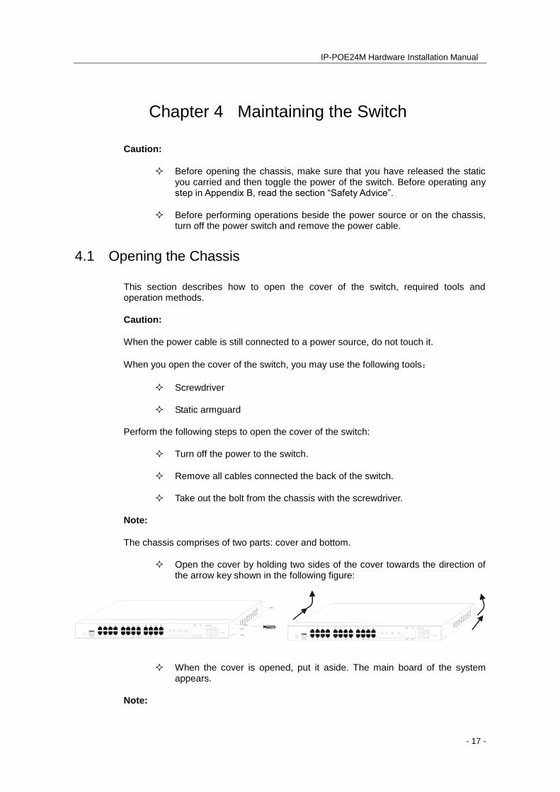
The chassis comprises of two parts: cover and bottom.
Open the cover by holding two sides of the cover towards the direction of the arrow key shown in the following figure:
When the cover is opened, put it aside. The main board of the system appears.
Note:
IP-POE24M Hardware Installation Manual
- 18 -
After taking off the cover, put it horizontally and avoid it being crushed or damaged. Otherwise, the chassis will be hard to install.
4.2 Closing Chassis
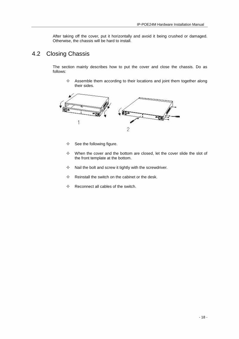
The section mainly describes how to put the cover and close the chassis. Do as follows:
Assemble them according to their locations and joint them together along their sides.
See the following figure.
When the cover and the bottom are closed, let the cover slide the slot of the front template at the bottom.
Nail the bolt and screw it tightly with the screwdriver.
Reinstall the switch on the cabinet or the desk.
Reconnect all cables of the switch.
IP-POE24M Hardware Installation Manual
- 19 -
Chapter 5 Hardware Fault Analysis
The part describes how to remove the fault from the switch.
5.1 Fault Identification (Troubleshooting)
The key for resolving systematic faults is to separate the fault from the system. You can compare what the system is doing with what the system should do to detect the fault. You need to check the following subsystems:
Power and cooling systems—power and fan
Port, cable and connection—ports on the front plate of the switch and the cables connecting these ports
5.1.1 Faults Relative with Power and Cooling System
Do the following checks to troubleshoot power / cooling issues:
When the power switch is at the “ON” location, check whether the fan works normally. If the fan does not work well, check the fan.
If the switch is too hot, check whether the air outlet and air inlet are clean and then do relative operations in section 2.3 “Requirements for Common Locations”. The working temperature of the switch is from 0 to 40 Celsius degrees.
If the switch cannot be started and the PWR indicator is off, check the power.
5.1.2 Faults Relative with Port, Cable and Connection
Do the following checkups to help remove the fault:
If the port of the switch cannot be linked, check whether the cable is correctly connected and whether the peer connection is normal.
If the power switch is at the “ON” location, check the power source and the power cable.
If the console port does not work after the system is started up, check whether the console port is set to a baud rate of 9600 bps, eight data bits, no sum check bit, one stop bit and no traffic control.
5.2 Indicator Description
The LED indicator shows that the switch is running. The following table shows the indicators of the IP-POE24M switch and their description:

IP-POE24M Hardware Installation Manual
- 20 -
No. Abbrev. Name Description
1 PWR Power indicator If the switch is powered on, the indicator
is on.
2 SYS System indicator
If the indicator is always on, the system
is being started.
If the indicator flickers, the system works
normally.
3 LINK/ACT Indicator of each port
If the indicator is always on, the link on
the port is normal.
If the indicator flickers, the data is
received or transmitted through the port.