Embed Size (px)
Citation preview
DS-6401HDI Series Decoder Server
USER MANUAL
Version 2.0.0
User Manual of DS-6401HDI Decoder
Hikvision Network Digital Video Recorder User’s Manual
This manual, as well as the software described in it, is furnished under license and may be used or copied only in
accordance with the terms of such license. The content of this manual is furnished for informational use only, is
subject to change without notice, and should not be construed as a commitment by Hikvision Digital Technology
Co., Ltd. (Hikvision). Hikvision assumes no responsibility or liability for any errors or inaccuracies that may
appear in the book.
Except as permitted by such license, no part of this publication may be reproduced, stored in a retrieval system,
or transmitted, in any form or by any means, electronic, mechanical, recording, or otherwise, without the prior
written permission of Hikvision.
HIKVISION MAKES NO WARRANTIES, EXPRESS OR IMPLIED, INCLUDING WITHOUT LIMITATION
THE IMPLIED WARRANTIES OF MERCHANTABILITY AND FITNESS FOR A PARTICULAR PURPOSE,
REGARDING THE HIKVISION SOFTWARE. HIKVISION DOES NOT WARRANT, GUARANTEE, OR
MAKE ANY REPRESENTATIONS REGARDING THE USE OR THE RESULTS OF THE USE OF THE
HIKVISION SOFTWARE IN TERMS OF ITS CORRECTNESS, ACCURACY, RELIABILITY,
CURRENTNESS, OR OTHERWISE. THE ENTIRE RISK AS TO THE RESULTS AND PERFORMANCE OF
THE HIKVISION SOFTWARE IS ASSUMED BY YOU. THE EXCLUSION OF IMPLIED WARRANTIES IS
NOT PERMITTED BY SOME STATES. THE ABOVE EXCLUSION MAY NOT APPLY TO YOU.
IN NO EVENT WILL HIKVISION, ITS DIRECTORS, OFFICERS, EMPLOYEES, OR AGENTS BE LIABLE
TO YOU FOR ANY CONSEQUENTIAL, INCIDENTAL, OR INDIRECT DAMAGES (INCLUDING
DAMAGES FOR LOSS OF BUSINESS PROFITS, BUSINESS INTERRUPTION, LOSS OF BUSINESS
INFORMATION, AND THE LIKE) ARISING OUT OF THE USE OR INABILITY TO USE THE HIKVISION
SOFTWARE EVEN IF HIKVISION HAS BEEN ADVISED OF THE POSSIBILITY OF SUCH DAMAGES.
BECAUSE SOME STATES DO NOT ALLOW THE EXCLUSION OR LIMITATION OF LIABILITY FOR
CONSEQUENTIAL OR INCIDENTAL DAMAGES, THE ABOVE LIMITATIONS MAY NOT APPLY TO
YOU.
1
User Manual of DS-6401HDI Decoder
Preventive and Cautionary Tips
Before connecting and operating your DVS, please be advised of the following tips:
• Ensure unit is installed in a well-ventilated, dust-free environment.
• Keep all liquids away from the DVS.
• Please check the power supply to avoid the damage caused by voltage mismatch.
• Please make sure the DVS work in the allowed range of temperature and humidity.
• Please keep the device horizontal and avoid the installation under severe vibration environment.
• The dust board will cause a short circuit after damping; Please dedust regularly for the board, connector,
chassis fan etc with brush.
• Improper use or replacement of the battery may result in hazard of explosion. Replace with the same or
equivalent type only. Dispose of used batteries according to the instructions provided by the battery
manufacturer.
2
User Manual of DS-6401HDI Decoder
TABLE OF CONTENTS CHAPTER 1 Introduction ...................................................................................................... 5
1.1 Description ...................................................................................................................... 6
1.2 Features ........................................................................................................................... 6
CHAPTER 2 Panel and Connections ........................................................................................ 9
2.1 Front Panel..................................................................................................................... 10
2.2 Rear Panel...................................................................................................................... 10
2.3 Alarm Connections ........................................................................................................ 11
2.3.1 Alarm Input Connections ....................................................................................... 11
2.3.2 Alarm Output Connections ..................................................................................... 11
2.3.3 Signal Line Connections......................................................................................... 12
CHAPTER 3 Network Parameters Configuration................................................................... 13
3.1 Hyper Terminal Setup ................................................................................................... 14
3.2 Network Configuration by Hyper Terminal .................................................................. 16
CHAPTER 4 Decoder Configuration ...................................................................................... 18
4.1 Decoder Configure Software ......................................................................................... 19
4.2 Add Decoder.................................................................................................................. 19
4.3 Decoder Configuration .................................................................................................. 21
4.4 TV Wall Settings ........................................................................................................... 23
4.5 Decoder Control ............................................................................................................ 25
4.5.1 Video Decoding...................................................................................................... 26
4.5.2 Cycle Decoding ...................................................................................................... 28
4.5.3 PTZ Control............................................................................................................ 29
CHAPTER 5 Third-party IP Camera Access ....................................................................... 31
5.1 Add Decoder.................................................................................................................. 32
5.2 Configure the Decoder .................................................................................................. 33
CHAPTER 6 Appendix ........................................................................................................... 36
Appendix A Specifications.................................................................................................. 37
Appendix B List of Third-party IP Cameras Access ........................................................... 38
3

User Manual of DS-6401HDI Decoder
4
Appendix C FAQ................................................................................................................. 41
Appendix D Glossary .......................................................................................................... 42

User Manual of DS-6401HDI Decoder
CHAPTER 1
Introduction
5
User Manual of DS-6401HDI Decoder
1.1 Description
Developed on the basis of TI DaVinci platform, DS-6401HDI is a kind of multi-purpose video/audio decoder which
is capable of allowing the coded images from DVR/DVS or other encoding devices to be decoded and displayed on
the TV wall after transmission via IP network. Specially designed for the allocation and management of the video
surveillance system, DS-6401HDI supports multiple network transmission protocols, and it applies the code
downloaded in FLASH, ensuring high stability and reliability of system performance.
DS-6401HDI Video/Audio Decoder adopts higher integrated TI DaVinci processing chip which provides powerful
decoding capability. It supports multiple bit rate transmission methods, and is capable of decoding /outputting the
high-definition 1080P video stream and outputting decoded images via BNC or VGA, HDMI andDVI ports
simultaneously. In addition, the Decoder also has the capabilities such as voice talk, alarm input/output, PTZ control,
etc., providing powerful support for the large-scale TV wall decoding service.
1.2 Features
Decoding
Decoding images and audio
Private H.264, standard H.264 and MPEG4 video compression methods;
Support PS, RTP and private customized encapsulation formats;
PAL and NTSC image formats;
Decoding at up to 1080P resolution;
G.722, G.711A and G.711U video compression methods.
Decoding Resources
DS-6401HDI is capable of decoding 1-ch video stream at 1080P resolution, 2-ch video at 720P resolution and
4-ch video at 4CIF resolution.
Decoding Mode
Multiple transmission methods: support TCP, UDP, MCAST and RTP transmission protocols.
Dynamic decoding: log on the remote encoder or remote stream media server to select a channel of video
source to acquire video stream, and then decode and output the video for local display.
Cycle decoding: set multiple remote monitoring channels on a decoding channel, and the decoder is capable of
performing cycle decoding according to the configured sequence and time. The stream sources can be obtained
via remote access to the encoder or stream media server and decoded for local output. A maximum of 64
channels are allowed for cycle decoding.
Obtain stream from stream media server: receive real-time data by remote access to stream media server, and
then decode stream for local output. The private RTSP is adopted as the control protocol, and the TCP/UDP is
used for receiving the data stream.
Remote playback of record files: by remote access to the encoder with storage capability, and directly obtain
the record files from the encoder, and finally decode for local output.
Passive decoding: the decoder passively receives stream sources, and then proceeds decoding and transmission.
Passive decoding supports TCP and UDP transmission modes.
Third-party IP Camera Access
6
User Manual of DS-6401HDI Decoder
Multiple brands of IP cameras from different manufactures are supported: Sony, Panasonic, Sanyo, Axis, Bosch,
etc. Please refer to Appendix B.
Network
One 10/100/1000Mbps self-adaptive UTP Ethernet interface.
Get allocated IP address, sub mask and gateway via DHCP server.
Accomplish auto time adjustment for decoder over NTP protocol.
Support DDNS capability.
Capable of searching decoder in real time through SADP software, as well as modifying the IP address, sub mask,
gateway of decoder and some other parameters.
Capable of accessing decoder by TELNET command to view device information, modify network parameters,
etc.
Alarm
Relay Alarm Input
The decoder provides alarm input/output ports in relay signal input mode which can be set to NO or NC. Eight
different arming periods can be set, in which the alarm occurs, the device is capable of triggering corresponding
alarm handling method, relay output and buzzer alarm, as well as upload to center, etc.
Relay Alarm Output
The relay alarm output can be connected to alarm devices for alarm response actions, e.g., combined aural and
visual alarm unit, etc., which is capable of proceeding alarm handling within the arming period.
Exception Handling
Exception Alarm Handling
Exception alarms include network disconnect alarm, IP address conflict alarm, illegal access alarm, etc.; multiple
alarm handling methods are supported: relay alarm output, buzzer alarm, upload to center, etc.
Exception Reboot
Software watchdog capability: for inspecting important threads and system resources of device; in case of
exceptions cannot be recovered, the device will be automatically rebooted.
Firmware watchdog: for inspecting the firmware of device; in case of exceptions in system task scheduling, the
device will be automatically rebooted.
User Administration
A maximum of 32 users can be created by the system, including 1 administrator and 31 users. The user name of
the administrator is admin, which cannot be modified, and the password is allowable to be modified by the
administrator only; no deletion of the administrator is allowed, and the administrator is authorized to set the
operation permissions for normal users.
SDK Interface
Transparent Channel
The decoder adopts the RS-232/RS-485 serial interface to realize transparent transmission. The data sent
remotely to the decoder via network can be transmitted by RS-232/RS-485 interface of decoder without any
handling, and the transparent channel of the decoder supports multi-cast transparent transmission as well, and
multiple transparent channels can be established simultaneously.
PTZ Control
7

User Manual of DS-6401HDI Decoder
Through SDK transparent channel, the PTZ of DVR or DVS can be remotely controlled.
Voice Talk
The decoder is capable of realizing voice talk with the remote client. When the client has submitted application,
the voice talk between the client and decoder is created.
8

User Manual of DS-6401HDI Decoder
CHAPTER 2
Panel and Connections
9
User Manual of DS-6401HDI Decoder
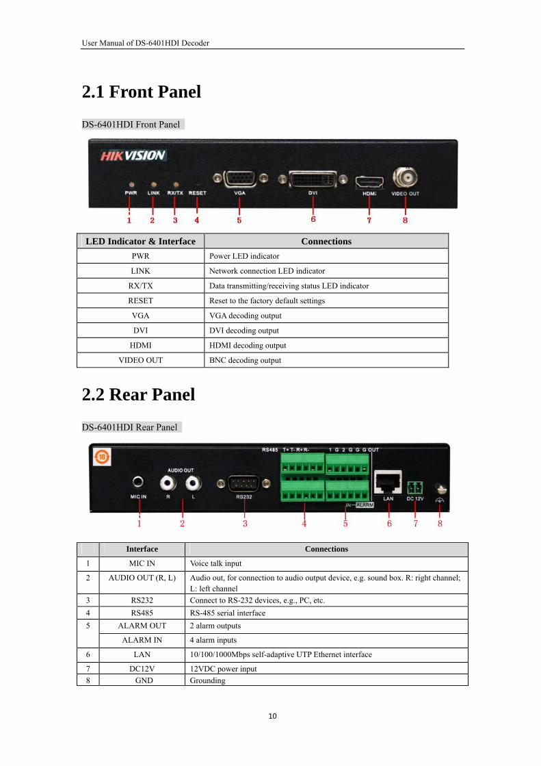
2.1 Front Panel
DS-6401HDI Front Panel
LED Indicator & Interface Connections
PWR Power LED indicator
LINK Network connection LED indicator
RX/TX Data transmitting/receiving status LED indicator
RESET Reset to the factory default settings
VGA VGA decoding output
DVI DVI decoding output
HDMI HDMI decoding output
VIDEO OUT BNC decoding output
2.2 Rear Panel
DS-6401HDI Rear Panel
Interface Connections
1 MIC IN Voice talk input
2 AUDIO OUT (R, L) Audio out, for connection to audio output device, e.g. sound box. R: right channel; L: left channel
3 RS232 Connect to RS-232 devices, e.g., PC, etc.
4 RS485 RS-485 serial interface
ALARM OUT 2 alarm outputs 5
ALARM IN 4 alarm inputs
6 LAN 10/100/1000Mbps self-adaptive UTP Ethernet interface
7 DC12V 12VDC power input
8 GND Grounding
10
User Manual of DS-6401HDI Decoder
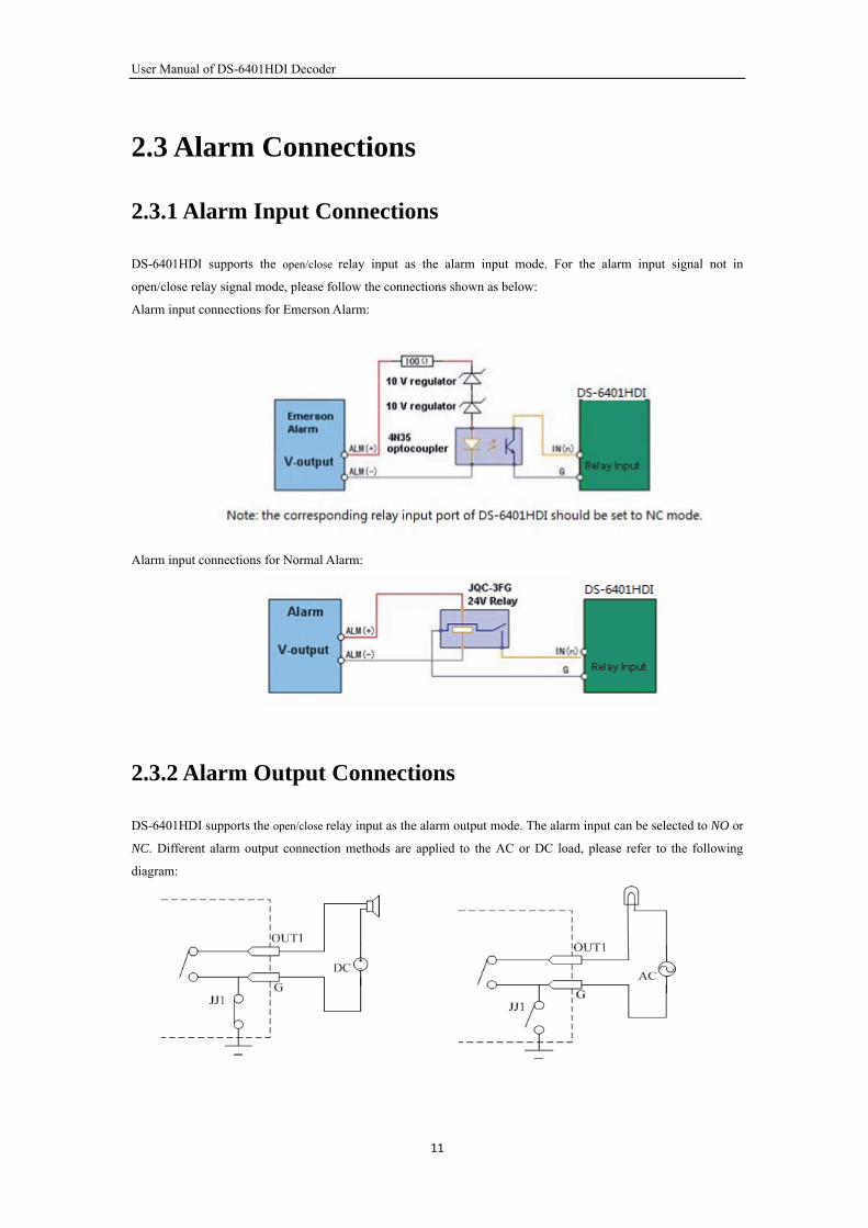
2.3 Alarm Connections
2.3.1 Alarm Input Connections
DS-6401HDI supports the open/close relay input as the alarm input mode. For the alarm input signal not in
open/close relay signal mode, please follow the connections shown as below:
Alarm input connections for Emerson Alarm:
Alarm input connections for Normal Alarm:
2.3.2 Alarm Output Connections
DS-6401HDI supports the open/close relay input as the alarm output mode. The alarm input can be selected to NO or
NC. Different alarm output connection methods are applied to the AC or DC load, please refer to the following
diagram:
11
User Manual of DS-6401HDI Decoder
Please note the different connections of JJ1 shown above.
For DC load, JJ1ca be safely used both in NC and NO methods, and it is recommended to use within the limit of
12V/1A. For external AC input, JJ1 must be open. The motherboard provides two jumpers, each corresponding to
one alarm output. By factory default, both of two jumpers are set to be connected.
2.3.3 Signal Line Connections
DS-6401HDI Decoder provides the green terminal plug for connecting signal lines. Follow the instructions shown
below:
1. Disconnect the green terminal plug from the terminal socket on the device;
2. Use the standard screwdriver to loosen the screws on the plug, and then insert signal lines to the plug and under
the spring washers, and finally tighten the screws.
3. Connect the plug with signal lines to the corresponding green terminal socket.
12
User Manual of DS-6401HDI Decoder
CHAPTER 3
Network Parameters Configuration
13
User Manual of DS-6401HDI Decoder
Description:
This chapter is about the network parameters configuration of DS-6401HDI Decoder.
The DS-6401HDI factory default user name is admin, and password is 12345.
The DS-6401HDI factory default IP address is 192.0.0.64.
The network parameters need to be setup before the decoding channel configuration. The network parameters are
used to connect with the software which is applied to set the decoding channels. The network parameters are
including IP address, subnet mask, gateway and port.
3.1 Hyper Terminal Setup
The common method is to connect decoder and PC with serial line, run Hyper Terminal and modify parameters with
serial command. Please connect the RS-232 port of decoder with the COM port of PC directly, power on the
decoder and PC and follow the steps:
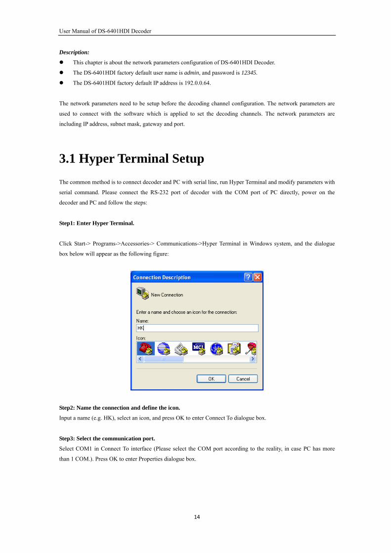
Step1: Enter Hyper Terminal.
Click Start-> Programs->Accessories-> Communications->Hyper Terminal in Windows system, and the dialogue
box below will appear as the following figure:
Step2: Name the connection and define the icon.
Input a name (e.g. HK), select an icon, and press OK to enter Connect To dialogue box.
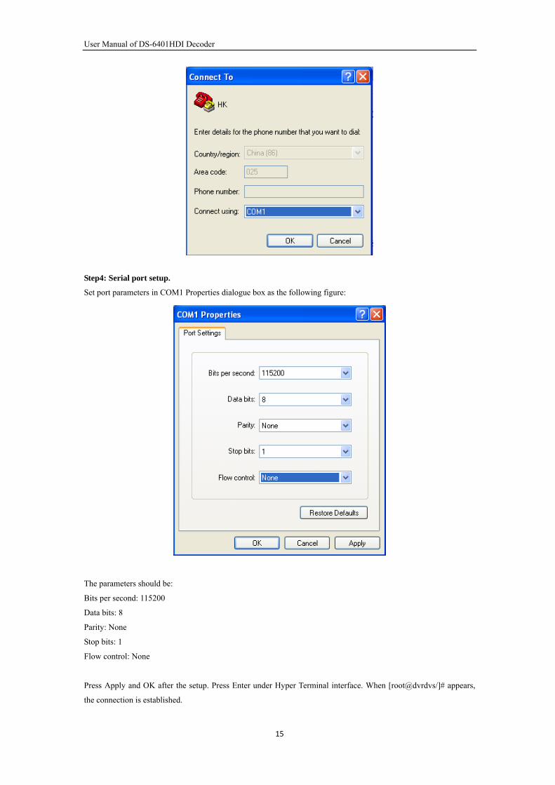
Step3: Select the communication port.
Select COM1 in Connect To interface (Please select the COM port according to the reality, in case PC has more
than 1 COM.). Press OK to enter Properties dialogue box.
14
User Manual of DS-6401HDI Decoder
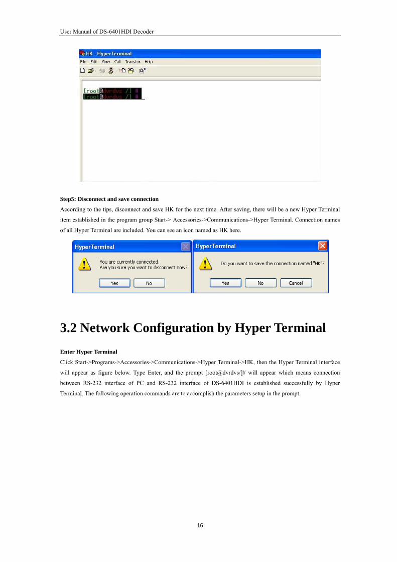
Step4: Serial port setup.
Set port parameters in COM1 Properties dialogue box as the following figure:
The parameters should be:
Bits per second: 115200
Data bits: 8
Parity: None
Stop bits: 1
Flow control: None
Press Apply and OK after the setup. Press Enter under Hyper Terminal interface. When [root@dvrdvs/]# appears,
the connection is established.
15
User Manual of DS-6401HDI Decoder
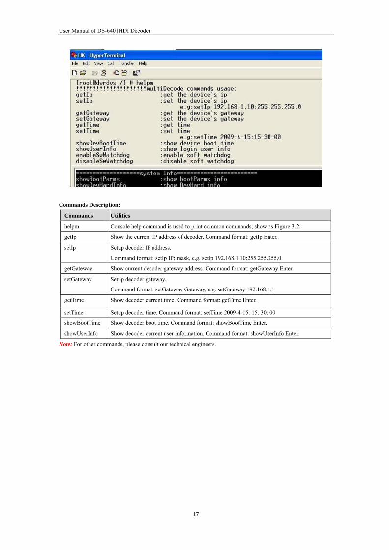
Step5: Disconnect and save connection
According to the tips, disconnect and save HK for the next time. After saving, there will be a new Hyper Terminal
item established in the program group Start-> Accessories->Communications->Hyper Terminal. Connection names
of all Hyper Terminal are included. You can see an icon named as HK here.
3.2 Network Configuration by Hyper Terminal
Enter Hyper Terminal
Click Start->Programs->Accessories->Communications->Hyper Terminal->HK, then the Hyper Terminal interface
will appear as figure below. Type Enter, and the prompt [root@dvrdvs/]# will appear which means connection
between RS-232 interface of PC and RS-232 interface of DS-6401HDI is established successfully by Hyper
Terminal. The following operation commands are to accomplish the parameters setup in the prompt.
16
User Manual of DS-6401HDI Decoder
Commands Description:
Commands Utilities
helpm Console help command is used to print common commands, show as Figure 3.2.
getIp Show the current IP address of decoder. Command format: getIp Enter.
setIp Setup decoder IP address.
Command format: setIp IP: mask, e.g. setIp 192.168.1.10:255.255.255.0
getGateway Show current decoder gateway address. Command format: getGateway Enter.
setGateway Setup decoder gateway.
Command format: setGateway Gateway, e.g. setGateway 192.168.1.1
getTime Show decoder current time. Command format: getTime Enter.
setTime Setup decoder time. Command format: setTime 2009-4-15: 15: 30: 00
showBootTime Show decoder boot time. Command format: showBootTime Enter.
showUserInfo Show decoder current user information. Command format: showUserInfo Enter.
Note: For other commands, please consult our technical engineers.
17
User Manual of DS-6401HDI Decoder
CHAPTER 4
Decoder Configuration
18
User Manual of DS-6401HDI Decoder
Instruction:
Before configuration, user need to do the network configure according to the chapter3.
Connect the decoder to the LAN.
Prepare a PC connected to the same LAN with the decoder.
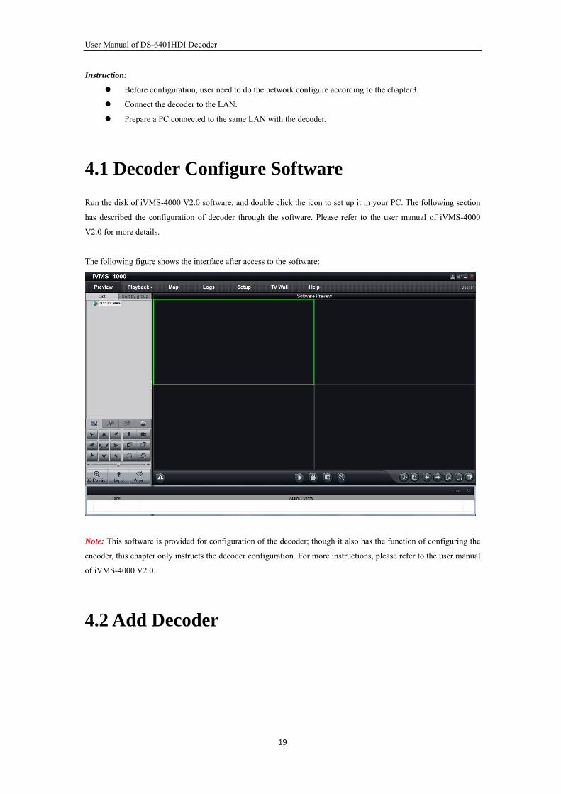
4.1 Decoder Configure Software
Run the disk of iVMS-4000 V2.0 software, and double click the icon to set up it in your PC. The following section
has described the configuration of decoder through the software. Please refer to the user manual of iVMS-4000
V2.0 for more details.
The following figure shows the interface after access to the software:
Note: This software is provided for configuration of the decoder; though it also has the function of configuring the
encoder, this chapter only instructs the decoder configuration. For more instructions, please refer to the user manual
of iVMS-4000 V2.0.
4.2 Add Decoder
19
User Manual of DS-6401HDI Decoder
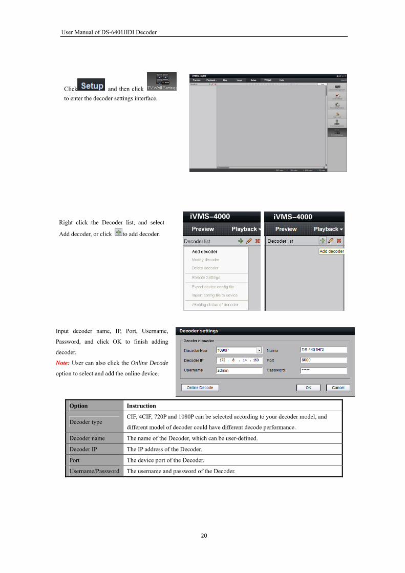
Click and then click
to enter the decoder settings interface.
Right click the Decoder list, and select
Add decoder, or click to add decoder.
Input decoder name, IP, Port, Username,
Password, and click OK to finish adding
decoder.
Note: User can also click the Online Decode
option to select and add the online device.
Option Instruction
Decoder type CIF, 4CIF, 720P and 1080P can be selected according to your decoder model, and
different model of decoder could have different decode performance.
Decoder name The name of the Decoder, which can be user-defined.
Decoder IP The IP address of the Decoder.
Port The device port of the Decoder.
Username/Password The username and password of the Decoder.
20
User Manual of DS-6401HDI Decoder
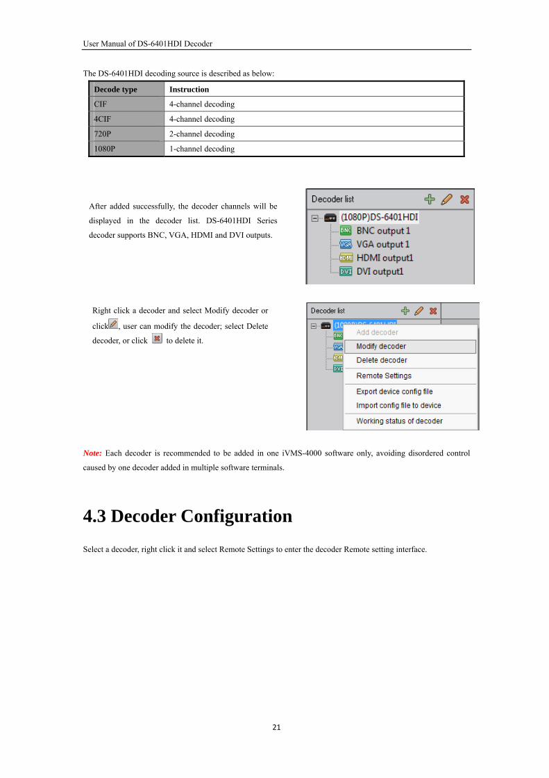
The DS-6401HDI decoding source is described as below:
Decode type Instruction
CIF 4-channel decoding
4CIF 4-channel decoding
720P 2-channel decoding
1080P 1-channel decoding
After added successfully, the decoder channels will be
displayed in the decoder list. DS-6401HDI Series
decoder supports BNC, VGA, HDMI and DVI outputs.
Right click a decoder and select Modify decoder or
click , user can modify the decoder; select Delete
decoder, or click to delete it.
Note: Each decoder is recommended to be added in one iVMS-4000 software only, avoiding disordered control
caused by one decoder added in multiple software terminals.
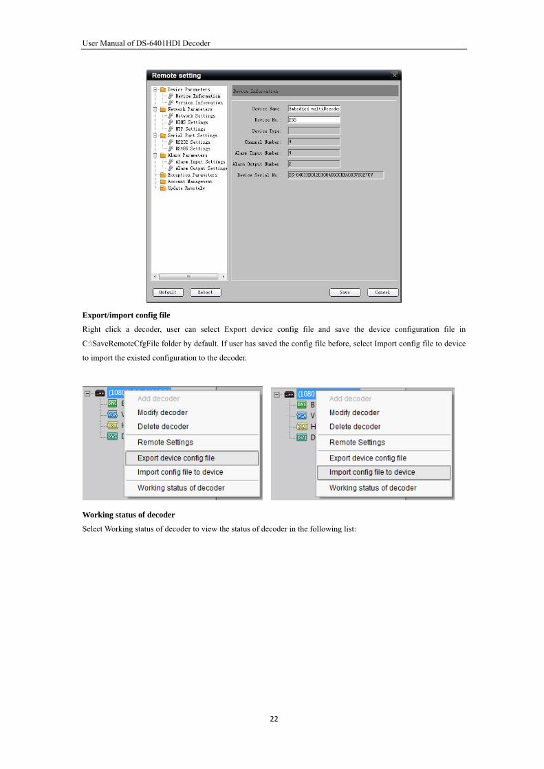
4.3 Decoder Configuration
Select a decoder, right click it and select Remote Settings to enter the decoder Remote setting interface.
21
User Manual of DS-6401HDI Decoder
Export/import config file
Right click a decoder, user can select Export device config file and save the device configuration file in
C:\SaveRemoteCfgFile folder by default. If user has saved the config file before, select Import config file to device
to import the existed configuration to the decoder.
Working status of decoder
Select Working status of decoder to view the status of decoder in the following list:
22

User Manual of DS-6401HDI Decoder
4.4 TV Wall Settings
Enable/Disable decode output
After having added the decoder, the
decoding channel is not in use by default.
Drag the channel to the blank interface on
the right to enable this channel.
When a channel is enabled, user may click
on the right bottom corner to disable this
channel.
Decode output settings
By double clicking a channel of the
decoder, user can configure the channel
name and video format to be PAL or
NTSC.
23
User Manual of DS-6401HDI Decoder
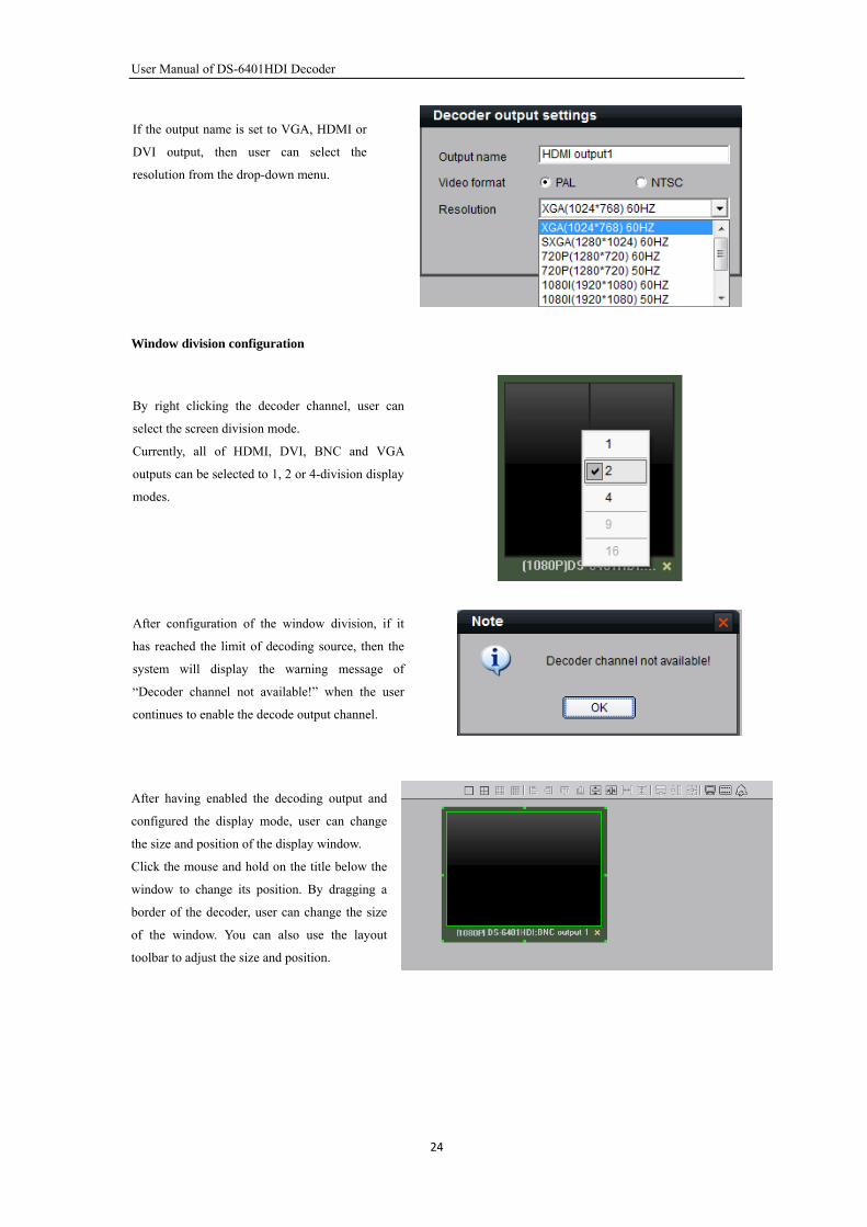
If the output name is set to VGA, HDMI or
DVI output, then user can select the
resolution from the drop-down menu.
Window division configuration
By right clicking the decoder channel, user can
select the screen division mode.
Currently, all of HDMI, DVI, BNC and VGA
outputs can be selected to 1, 2 or 4-division display
modes.
After configuration of the window division, if it
has reached the limit of decoding source, then the
system will display the warning message of
“Decoder channel not available!” when the user
continues to enable the decode output channel.
After having enabled the decoding output and
configured the display mode, user can change
the size and position of the display window.
Click the mouse and hold on the title below the
window to change its position. By dragging a
border of the decoder, user can change the size
of the window. You can also use the layout
toolbar to adjust the size and position.
24
User Manual of DS-6401HDI Decoder
Refer to the following table for the description of layout toolbar:
Button Description Button Description
Align left Flush right
Align top Flush bottom
Vertical center Horizontal center
Equal horizontal interval Equal vertical interval
Equal width Equal height
Equal size
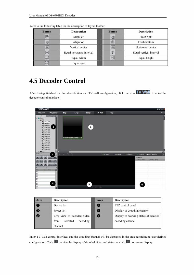
4.5 Decoder Control
After having finished the decoder addition and TV wall configuration, click the icon to enter the
decoder control interface:
Area Description Area Description
Device list PTZ control panel
Preset list Display of decoding channel
Live view of decoded video
from selected decoding
channel
Display of working status of selected
decoding channel
Enter TV Wall control interface, and the decoding channel will be displayed in the area according to user-defined
configuration. Click to hide the display of decoded video and status, or click to resume display.
25
User Manual of DS-6401HDI Decoder
Description of the functional buttons on the interface:
Button Description Button Description
Start playing the decoded video Stop playing the decoded video
Start cycle decoding Stop cycle decoding
Start/Stop the live view of local
decoded video
Capture
Record
Note: The display of TV wall will not be affected by starting or stopping the live view of decoded video.
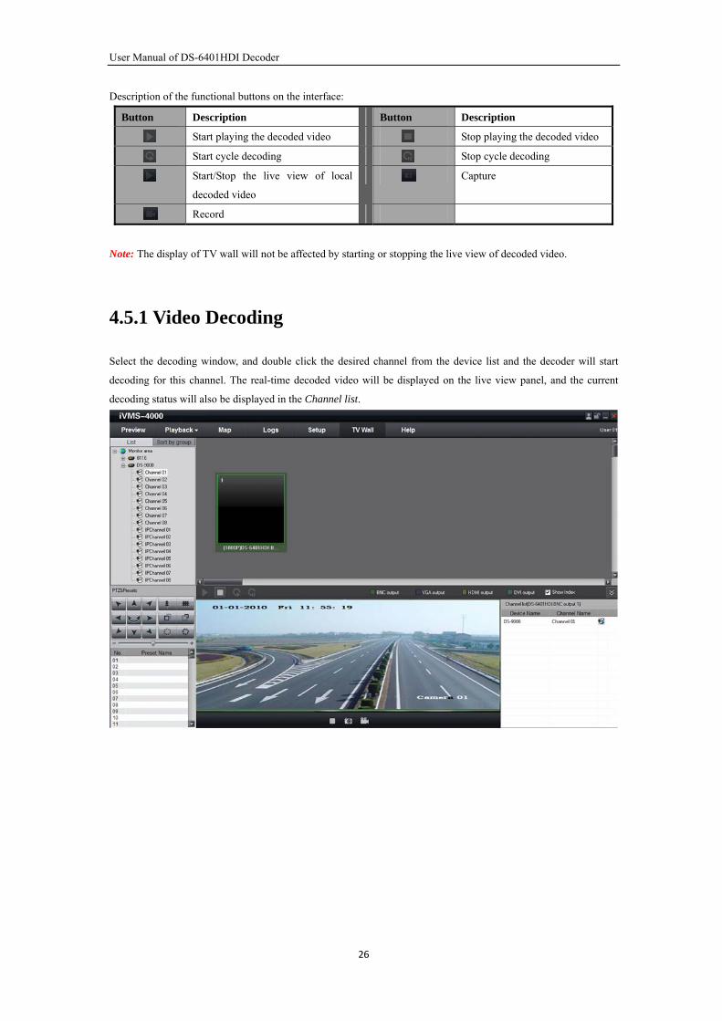
4.5.1 Video Decoding
Select the decoding window, and double click the desired channel from the device list and the decoder will start
decoding for this channel. The real-time decoded video will be displayed on the live view panel, and the current
decoding status will also be displayed in the Channel list.
26
User Manual of DS-6401HDI Decoder
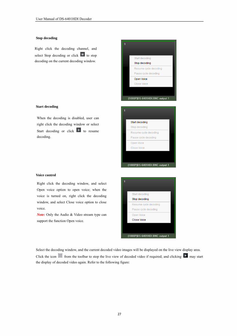
Stop decoding
Right click the decoding channel, and
select Stop decoding or click to stop
decoding on the current decoding window.
Start decoding
When the decoding is disabled, user can
right click the decoding window or select
Start decoding or click to resume
decoding.
Voice control
Decoded video control
Right click the decoding window, and select
Open voice option to open voice; when the
voice is turned on, right click the decoding
window, and select Close voice option to close
voice.
Note: Only the Audio & Video stream type can
support the function Open voice.
Select the decoding window, and the current decoded video images will be displayed on the live view display area.
Click the icon from the toolbar to stop the live view of decoded video if required; and clicking may start
the display of decoded video again. Refer to the following figure:
27
User Manual of DS-6401HDI Decoder
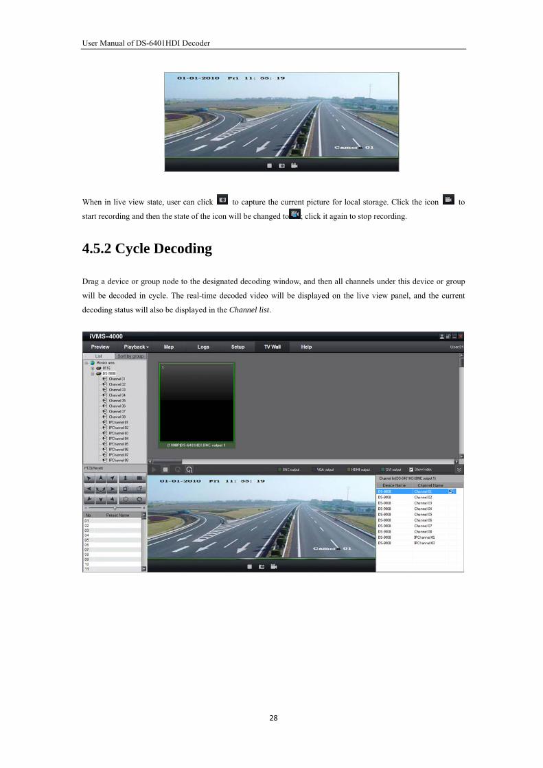
When in live view state, user can click to capture the current picture for local storage. Click the icon to
start recording and then the state of the icon will be changed to ; click it again to stop recording.
4.5.2 Cycle Decoding
Drag a device or group node to the designated decoding window, and then all channels under this device or group
will be decoded in cycle. The real-time decoded video will be displayed on the live view panel, and the current
decoding status will also be displayed in the Channel list.
28
User Manual of DS-6401HDI Decoder
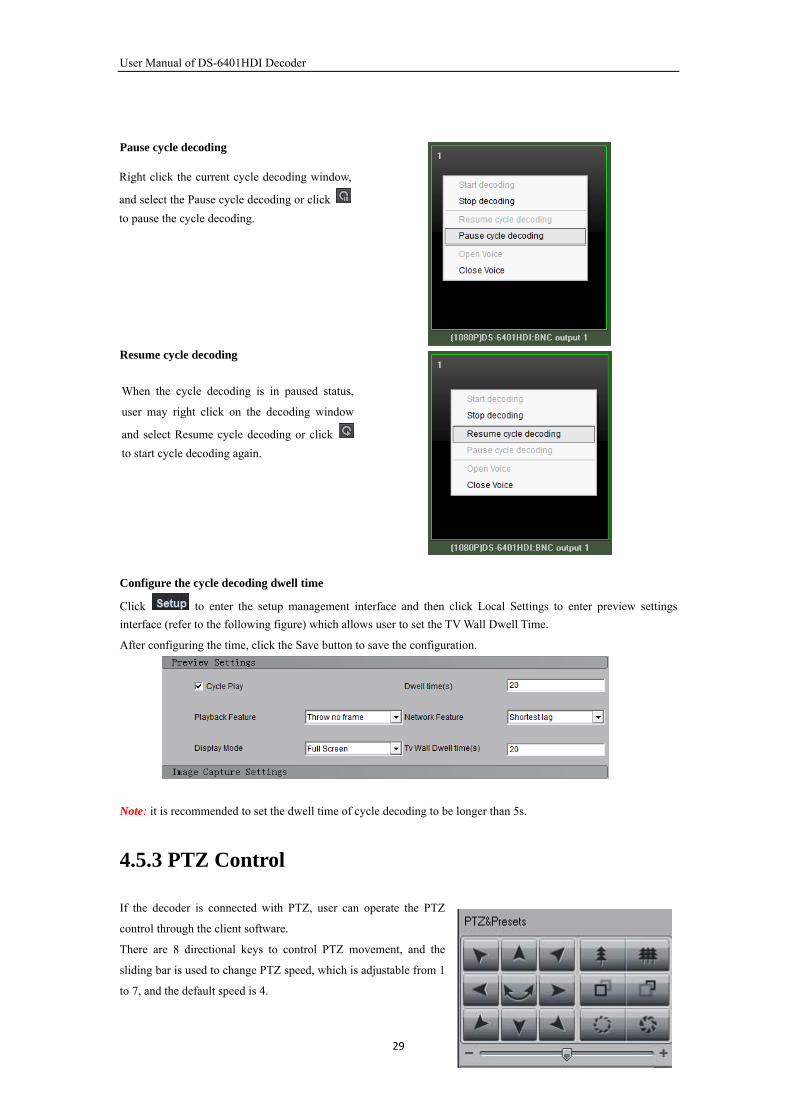
Pause cycle decoding
Right click the current cycle decoding window,
and select the Pause cycle decoding or click
to pause the cycle decoding.
Resume cycle decoding
When the cycle decoding is in paused status,
user may right click on the decoding window
and select Resume cycle decoding or click
to start cycle decoding again.
Configure the cycle decoding dwell time
Click to enter the setup management interface and then click Local Settings to enter preview settings
interface (refer to the following figure) which allows user to set the TV Wall Dwell Time.
After configuring the time, click the Save button to save the configuration.
Note: it is recommended to set the dwell time of cycle decoding to be longer than 5s.
4.5.3 PTZ Control
If the decoder is connected with PTZ, user can operate the PTZ
control through the client software.
There are 8 directional keys to control PTZ movement, and the
sliding bar is used to change PTZ speed, which is adjustable from 1
to 7, and the default speed is 4.
29
User Manual of DS-6401HDI Decoder
Click key to start auto scanning and click it again to stop scanning.
Click the function keys on the right to adjust focus, iris and zoom.
If the PC is connected with 1002KI/1003KI keyboard or USB joystick, the PTZ can also be controlled by them.
Note: If the current decoding window is under cycle decoding, the cycle decoding will be paused while operating
PTZ control; and when the PTZ control is finished, the cycle decoding will be resumed.
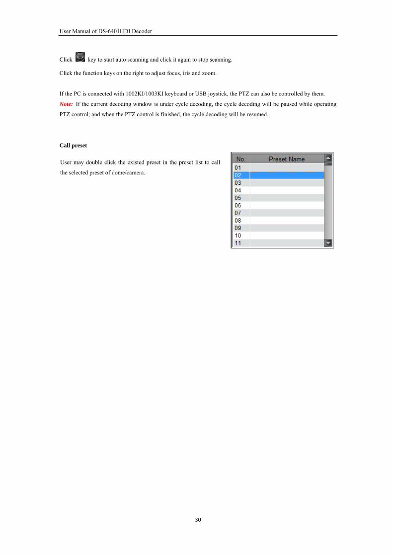
Call preset
User may double click the existed preset in the preset list to call
the selected preset of dome/camera.
30
User Manual of DS-6401HDI Decoder
CHAPTER 5
Third-party IP Camera Access
31
User Manual of DS-6401HDI Decoder
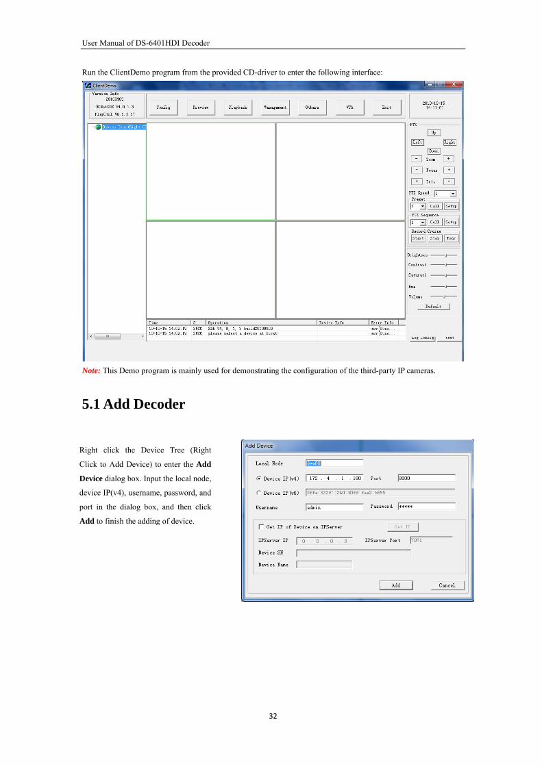
Run the ClientDemo program from the provided CD-driver to enter the following interface:
Note: This Demo program is mainly used for demonstrating the configuration of the third-party IP cameras.
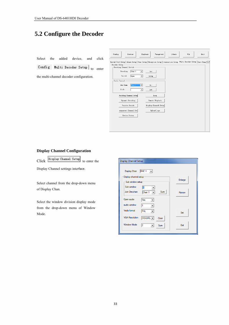
5.1 Add Decoder
Right click the Device Tree (Right
Click to Add Device) to enter the Add
Device dialog box. Input the local node,
device IP(v4), username, password, and
port in the dialog box, and then click
Add to finish the adding of device.
32
User Manual of DS-6401HDI Decoder
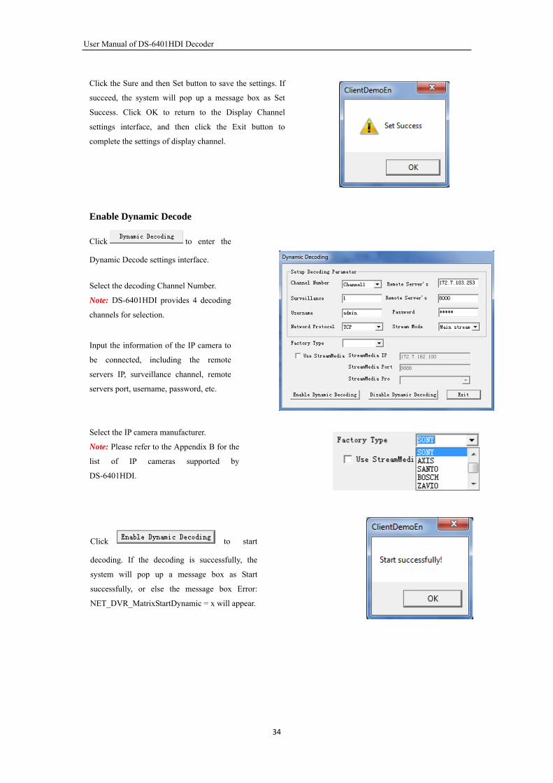
5.2 Configure the Decoder
Select the added device, and click
to enter
the multi-channel decoder configuration.
33
Select the window division display mode
from the drop-down menu of Window
Mode.
Select channel from the drop-down menu
of Display Chan.
Display Channel Configuration
Click to enter the
Display Channel settings interface.
User Manual of DS-6401HDI Decoder
Click the Sure and then Set button to save the settings. If
succeed, the system will pop up a message box as Set
Success. Click OK to return to the Display Channel
settings interface, and then click the Exit button to
complete the settings of display channel.
Enable Dynamic Decode
Click to enter the
Dynamic Decode settings interface.
Select the decoding Channel Number.
Note: DS-6401HDI provides 4 decoding
channels for selection.
Input the information of the IP camera to
be connected, including the remote
servers IP, surveillance channel, remote
servers port, username, password, etc.
Select the IP camera manufacturer.
Note: Please refer to the Appendix B for the
list of IP cameras supported by
DS-6401HDI.
Click to start
decoding. If the decoding is successfully, the
system will pop up a message box as Start
successfully, or else the message box Error:
NET_DVR_MatrixStartDynamic = x will appear.
34
User Manual of DS-6401HDI Decoder
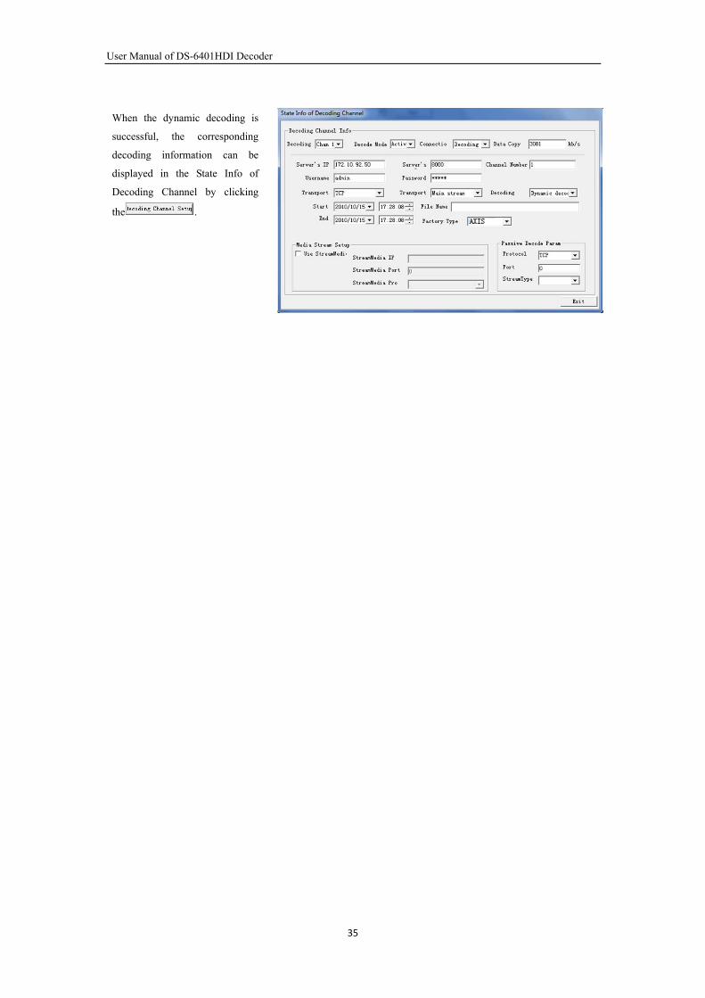
When the dynamic decoding is
successful, the corresponding
decoding information can be
displayed in the State Info of
Decoding Channel by clicking
the .
35

User Manual of DS-6401HDI Decoder
CHAPTER 6
Appendix
36
User Manual of DS-6401HDI Decoder
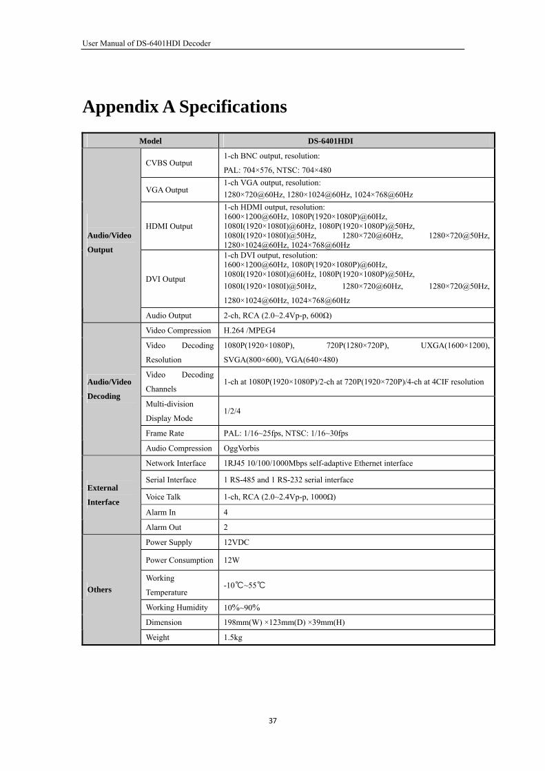
Appendix A Specifications
Model DS-6401HDI
CVBS Output 1-ch BNC output, resolution:
PAL: 704×576, NTSC: 704×480
VGA Output 1-ch VGA output, resolution:
1280×720@60Hz, 1280×1024@60Hz, 1024×768@60Hz
HDMI Output
1-ch HDMI output, resolution: 1600×1200@60Hz, 1080P(1920×1080P)@60Hz, 1080I(1920×1080I)@60Hz, 1080P(1920×1080P)@50Hz, 1080I(1920×1080I)@50Hz, 1280×720@60Hz, 1280×720@50Hz, 1280×1024@60Hz, 1024×768@60Hz
DVI Output
1-ch DVI output, resolution: 1600×1200@60Hz, 1080P(1920×1080P)@60Hz, 1080I(1920×1080I)@60Hz, 1080P(1920×1080P)@50Hz,
1080I(1920×1080I)@50Hz, 1280×720@60Hz, 1280×720@50Hz,
1280×1024@60Hz, 1024×768@60Hz
Audio/Video
Output
Audio Output 2-ch, RCA (2.0~2.4Vp-p, 600Ω)
Video Compression H.264 /MPEG4
Video Decoding
Resolution
1080P(1920×1080P), 720P(1280×720P), UXGA(1600×1200),
SVGA(800×600), VGA(640×480)
Video Decoding
Channels 1-ch at 1080P(1920×1080P)/2-ch at 720P(1920×720P)/4-ch at 4CIF resolution
Multi-division
Display Mode 1/2/4
Frame Rate PAL: 1/16~25fps, NTSC: 1/16~30fps
Audio/Video
Decoding
Audio Compression OggVorbis
Network Interface 1RJ45 10/100/1000Mbps self-adaptive Ethernet interface
Serial Interface 1 RS-485 and 1 RS-232 serial interface
Voice Talk 1-ch, RCA (2.0~2.4Vp-p, 1000Ω)
Alarm In 4
External
Interface
Alarm Out 2
Power Supply 12VDC
Power Consumption 12W
Working
Temperature -10~55
Working Humidity 10%~90%
Dimension 198mm(W) ×123mm(D) ×39mm(H)
Others
Weight 1.5kg
37
User Manual of DS-6401HDI Decoder
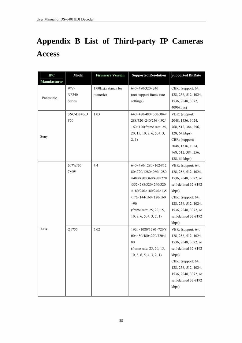
Appendix B List of Third-party IP Cameras
Access
IPC
Manufacturer
Model Firmware Version Supported Resolution Supported BitRate
Panasonic
WV-
NP240
Series
1.00Ex(x stands for
numeric)
640×480/320×240
(not support frame rate
settings)
CBR: (support: 64,
128, 256, 512, 1024,
1536, 2048, 3072,
4096kbps)
Sony
SNC-DF40/D
F70
1.03 640×480/480×360/384×
288/320×240/256×192/
160×120(frame rate: 25,
20, 15, 10, 8, 6, 5, 4, 3,
2, 1)
VBR: (support:
2048, 1536, 1024,
768, 512, 384, 256,
128, 64 kbps)
CBR: (support:
2048, 1536, 1024,
768, 512, 384, 256,
128, 64 kbps)
207W/20
7MW
4.4 640×480/1280×1024/12
80×720/1280×960/1280
×480/480×360/480×270
/352×288/320×240/320
×180/240×180/240×135
/176×144/160×120/160
×90
(frame rate: 25, 20, 15,
10, 8, 6, 5, 4, 3, 2, 1)
VBR: (support: 64,
128, 256, 512, 1024,
1536, 2048, 3072, or
self-defined 32-8192
kbps)
CBR: (support: 64,
128, 256, 512, 1024,
1536, 2048, 3072, or
self-defined 32-8192
kbps)
Axis Q1755 5.02 1920×1080/1280×720/8
00×450/480×270/320×1
80
(frame rate: 25, 20, 15,
10, 8, 6, 5, 4, 3, 2, 1)
VBR: (support: 64,
128, 256, 512, 1024,
1536, 2048, 3072, or
self-defined 32-8192
kbps)
CBR: (support: 64,
128, 256, 512, 1024,
1536, 2048, 3072, or
self-defined 32-8192
kbps)
38
User Manual of DS-6401HDI Decoder
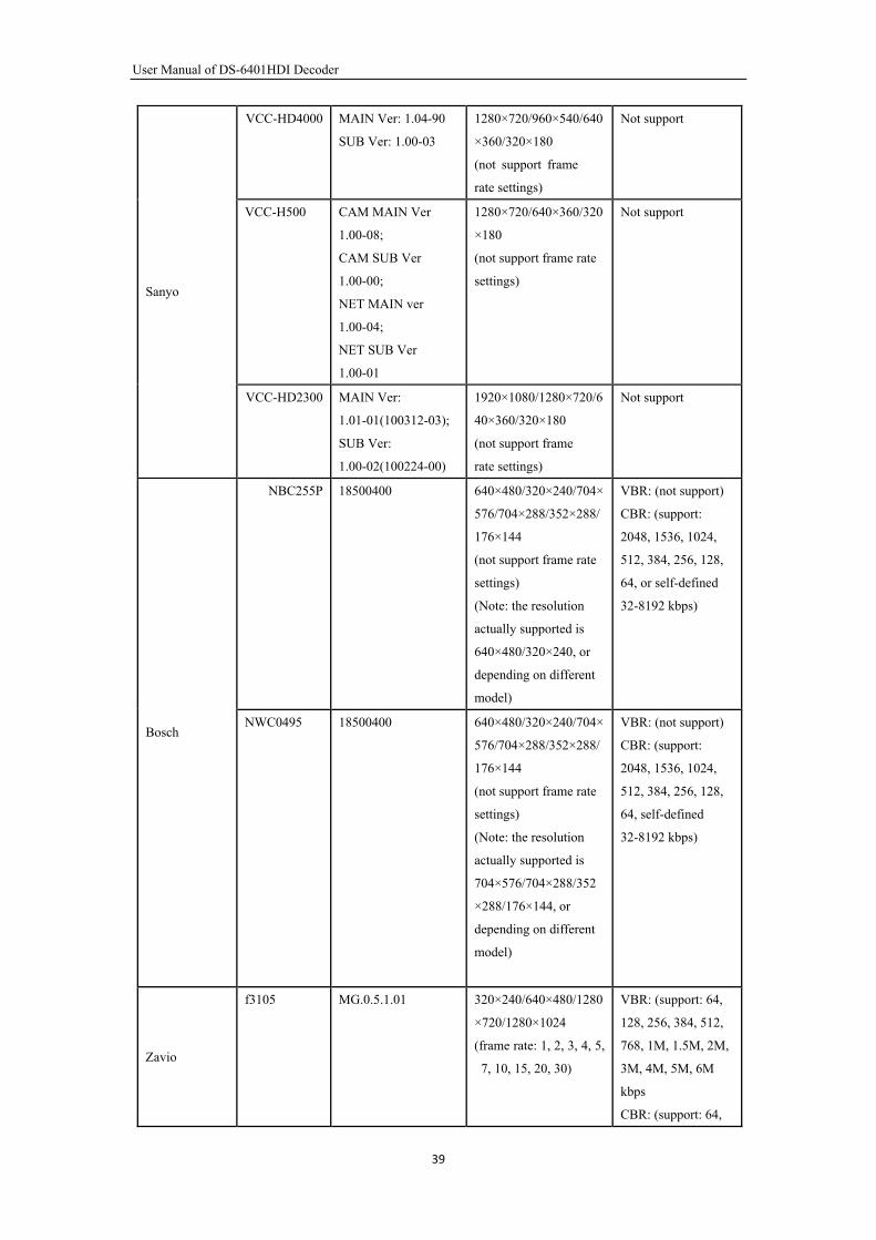
VCC-HD4000 MAIN Ver: 1.04-90
SUB Ver: 1.00-03
1280×720/960×540/640
×360/320×180
(not support frame
rate settings)
Not support
VCC-H500 CAM MAIN Ver
1.00-08;
CAM SUB Ver
1.00-00;
NET MAIN ver
1.00-04;
NET SUB Ver
1.00-01
1280×720/640×360/320
×180
(not support frame rate
settings)
Not support
Sanyo
VCC-HD2300 MAIN Ver:
1.01-01(100312-03);
SUB Ver:
1.00-02(100224-00)
1920×1080/1280×720/6
40×360/320×180
(not support frame
rate settings)
Not support
NBC255P 18500400 640×480/320×240/704×
576/704×288/352×288/
176×144
(not support frame rate
settings)
(Note: the resolution
actually supported is
640×480/320×240, or
depending on different
model)
VBR: (not support)
CBR: (support:
2048, 1536, 1024,
512, 384, 256, 128,
64, or self-defined
32-8192 kbps)
Bosch NWC0495 18500400 640×480/320×240/704×
576/704×288/352×288/
176×144
(not support frame rate
settings)
(Note: the resolution
actually supported is
704×576/704×288/352
×288/176×144, or
depending on different
model)
VBR: (not support)
CBR: (support:
2048, 1536, 1024,
512, 384, 256, 128,
64, self-defined
32-8192 kbps)
Zavio
f3105 MG.0.5.1.01 320×240/640×480/1280
×720/1280×1024
(frame rate: 1, 2, 3, 4, 5,
7, 10, 15, 20, 30)
VBR: (support: 64,
128, 256, 384, 512,
768, 1M, 1.5M, 2M,
3M, 4M, 5M, 6M
kbps
CBR: (support: 64,
39
User Manual of DS-6401HDI Decoder
128, 256, 384, 512,
768, 1M, 1.5M, 2M,
3M, 4M, 5M, 6M
kbps)
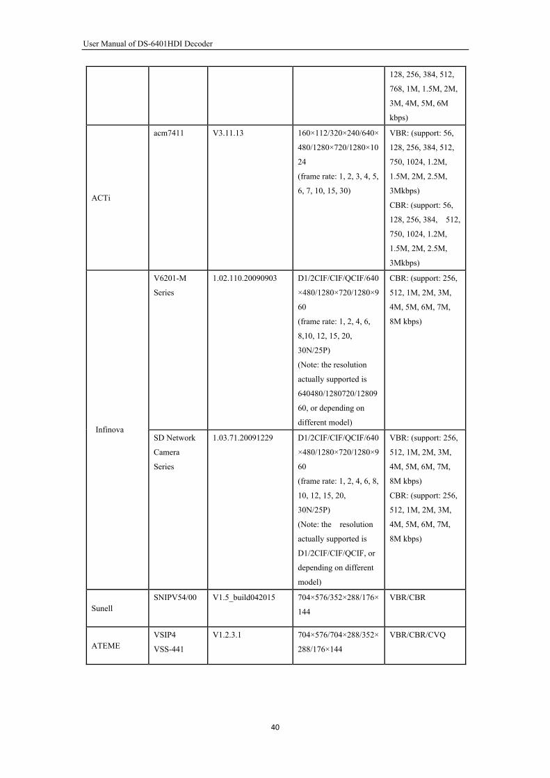
ACTi
acm7411 V3.11.13 160×112/320×240/640×
480/1280×720/1280×10
24
(frame rate: 1, 2, 3, 4, 5,
6, 7, 10, 15, 30)
VBR: (support: 56,
128, 256, 384, 512,
750, 1024, 1.2M,
1.5M, 2M, 2.5M,
3Mkbps)
CBR: (support: 56,
128, 256, 384, 512,
750, 1024, 1.2M,
1.5M, 2M, 2.5M,
3Mkbps)
V6201-M
Series
1.02.110.20090903 D1/2CIF/CIF/QCIF/640
×480/1280×720/1280×9
60
(frame rate: 1, 2, 4, 6,
8,10, 12, 15, 20,
30N/25P)
(Note: the resolution
actually supported is
640480/1280720/12809
60, or depending on
different model)
CBR: (support: 256,
512, 1M, 2M, 3M,
4M, 5M, 6M, 7M,
8M kbps)
Infinova SD Network
Camera
Series
1.03.71.20091229 D1/2CIF/CIF/QCIF/640
×480/1280×720/1280×9
60
(frame rate: 1, 2, 4, 6, 8,
10, 12, 15, 20,
30N/25P)
(Note: the resolution
actually supported is
D1/2CIF/CIF/QCIF, or
depending on different
model)
VBR: (support: 256,
512, 1M, 2M, 3M,
4M, 5M, 6M, 7M,
8M kbps)
CBR: (support: 256,
512, 1M, 2M, 3M,
4M, 5M, 6M, 7M,
8M kbps)
Sunell SNIPV54/00 V1.5_build042015 704×576/352×288/176×
144
VBR/CBR
ATEME VSIP4
VSS-441
V1.2.3.1 704×576/704×288/352×
288/176×144
VBR/CBR/CVQ
40
User Manual of DS-6401HDI Decoder
Appendix C FAQ
Why cannot ping the decoder?
Please refer to Chapter 3 to configure the decoder IP address being in the same segment as your PC, and
check the cable and switch.
Why the transparent channel has been set, but the encoder still cannot receive data?
1: Check if RS232 has been set as transparent channel first.
2: Check the connection of encoder.
Why cannot add decoder with software?
1: Check the decoder IP address.
2: Cable is connected.
3: User name and password of decoder are correct.
Why cannot play back the recorded file in DVR with decoder?
1: Check the DVR network connection.
2: Check the parameters of the playback file.
3: Check if there are files existed in the selected time range.
Why cannot decode the stream transported by stream media server?
1: Check the network connection between decoder and stream media server.
2: Check if the stream media server port is connected with the port added on decoder.
41
User Manual of DS-6401HDI Decoder
Appendix D Glossary
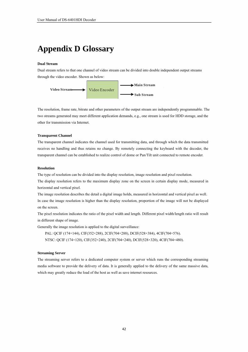
Dual Stream
Dual stream refers to that one channel of video stream can be divided into double independent output streams
through the video encoder. Shown as below:
Video Stream Video EncoderMain Stream
Sub Stream
The resolution, frame rate, bitrate and other parameters of the output stream are independently programmable. The
two streams generated may meet different application demands, e.g., one stream is used for HDD storage, and the
other for transmission via Internet.
Transparent Channel
The transparent channel indicates the channel used for transmitting data, and through which the data transmitted
receives no handling and thus retains no change. By remotely connecting the keyboard with the decoder, the
transparent channel can be established to realize control of dome or Pan/Tilt unit connected to remote encoder.
Resolution
The type of resolution can be divided into the display resolution, image resolution and pixel resolution.
The display resolution refers to the maximum display zone on the screen in certain display mode, measured in
horizontal and vertical pixel.
The image resolution describes the detail a digital image holds, measured in horizontal and vertical pixel as well.
In case the image resolution is higher than the display resolution, proportion of the image will not be displayed
on the screen.
The pixel resolution indicates the ratio of the pixel width and length. Different pixel width/length ratio will result
in different shape of image.
Generally the image resolution is applied to the digital surveillance:
PAL: QCIF (174×144), CIF(352×288), 2CIF(704×288), DCIF(528×384), 4CIF(704×576).
NTSC: QCIF (174×120), CIF(352×240), 2CIF(704×240), DCIF(528×320), 4CIF(704×480).
Streaming Server
The streaming server refers to a dedicated computer system or server which runs the corresponding streaming
media software to provide the delivery of data. It is generally applied to the delivery of the same massive data,
which may greatly reduce the load of the host as well as save internet resources.
42