Embed Size (px)
Citation preview
Other
Information
Changing
Settings
Scale, A
nnotation,
and Me
asurement
Functions
Photographing and
Replaying Im
ages P
hotographing B
asics of DS
-L4 P
lease Read
First
DS-L4
Microscope Camera Control Unit
Instructions
Camera Operation
M668 E 16.9.Nx.1 (1/2)

Introduction
i
Intro
du
ction
Introduction
Thank you for purchasing a Nikon product.
This instruction manual has been prepared for users of the Nikon DS-L4 Microscope Camera Control Unit. To ensure correct
usage, read this manual carefully before operating this product.
No part of this manual may be reproduced or transmitted in any form without prior written permission from Nikon.
The contents of this manual are subject to change without notice.
The equipment described in this manual may differ from the actual product in its appearance.
Although every effort has been made to ensure the accuracy of this manual, errors or inconsistencies may remain. If you note
any points that are unclear or incorrect, please contact your nearest Nikon representative.
Some of the equipment described in this manual may not be included in the set you have purchased.
If you intend to use any other equipment with this product, read the manual for that equipment too.
If this equipment is used in a manner not specified by the manufacturer, the protection provided by the equipment may be
impaired.
Symbols used in this manual
This manual uses the following symbols.
This icon marks precautions or information that should be observed for safety. Depending on the severity of the risk,
"WARNING" and "CAUTION" are indicated together with this icon.
This icon marks precautions or information that should be observed to avoid malfunction and failure of this product.
This icon marks notes or information that should be read before use. It also marks tips or additional information that
may be helpful when using this product.
Trademarks in this manual
Windows is a registered trademark of Microsoft Corporation in the United States and other countries.
Mac OS and iMac are trademarks of Apple Inc.
Android is a trademark of Google Inc.
DisplayPort is a trademark or registered trademark of Video Electronics Standards Association.
HDMI is a trademark or registered trademark of HDMI Licensing, LLC.
Bluetooth is a trademark of Bluetooth SIG, Inc.
microSD, microSDHC, and microSDXC are trademarks of SD-3C, LLC.
Products and brand names are trademarks or registered trademarks of their respective companies.
In this manual, "TM" and ® marks are not used to identify registered trademarks and trademarks.
DICOM is a standard that defines medical image formats and communication protocols. Manuals The documentation for the DS-L4 Microscope Camera Control Unit consists of the following three manuals:
Camera Operation (this manual) Explains how to install and connect DS-L4, the operation of the touch panel, and the
operation of the microscope camera connected to DS-L4.
Quick Reference
Provides a brief explanation on how to operate the DS-L4.
Microscope Operation
Explains how to operate and check the status of the microscope on the DS-L4 screen.
Features of This Product
ii
Fe
atu
res o
f Th
is Pro
du
ct
Features of This Product
The Nikon DS-L4 Microscope Camera Control Unit is a device to photograph or replay images with a Nikon microscope
camera connected.
The live image displayed on the touch panel LCD display can be captured and saved as a still image or motion image to a
storage media device such as a microSD card or USB drive. You can replay captured images, add annotations, or apply
measurements on the screen.
This device is equipped with a microscope control function, providing both on-screen electric control and status display of
motorized accessories of a Nikon microscope.
Microscope camera support
The Nikon DS-Fi3 microscope camera can be connected.
Built-in touch panel LCD display
This product is equipped with a 10.1-inch wide touch panel LCD display enabling on-screen operation for viewing and
capturing live images, replaying captured images, and configuring camera and microscope settings. A commercially
available USB mouse or Bluetooth mouse can be used for operation. A user-friendly, button-based interface provides
access to various DS-L4 functions.
Support for internal drives, microSD cards, USB memory drives, and network drives
Captured still images and motion images can be saved to an internal drive, network drive, microSD card, or USB
memory drive. You can specify the drive (or media) and folder in which you want to save images.
Output to an external display
Images can be output to any commercially available WUXGA external display via the analog RGB or DisplayPort
interface.
Consecutive capture with an interval timer
Multiple images can be automatically captured at intervals by specifying the number of images and the interval length.
This function allows you to observe how a subject changes or to photograph a subject consecutively with different
photographing conditions.
Interval recording with an interval timer
Motion images can be recorded automatically at regular intervals by specifying the recording time, the interval length,
and the number of motion images to be recorded. This function allows you to observe how a subject changes.
Annotations to images
You can add scales (such as a scale bar and grid) and annotations (such as text, lines, and count markers) to live and
playback images. Images can be captured with annotations added.
Easy on-screen measurement
Lengths and angles can be measured easily by on-screen operation.
Networking
By connecting the DS-L4 to a network, images can be saved to a network drive. Images saved on a network drive can
also be retrieved from a viewer terminal.
Microscope control
This device is equipped with a microscope control function, providing both on-screen control and status display of
motorized accessories of a connected Nikon microscope. For details, refer to the section "Microscope Operation".
The hardware of this product is a tablet terminal, ARROWS Tab Q555/K64, manufactured by Fujitsu Limited.
Contents
iii
Co
nte
nts
Contents
Introduction ........................................................................................................................................................................... i Manuals ................................................................................................................................................................................ i Features of This Product ..................................................................................................................................................... ii
Part1 Please Read First
Before Use ................................................................................................................................................................ 2
1.1 Confirmation of Accessories ................................................................................................................................... 2 1.2 Microscope Cameras Supported by the DS-L4 ..................................................................................................... 3 1.3 Peripheral Devices That Can Be Used .................................................................................................................. 4
Names of Parts ......................................................................................................................................................... 6
2.1 DS-L4 Microscope Camera Control Unit ................................................................................................................ 6 2.2 Cradle ..................................................................................................................................................................... 8
Installation and Connection ..................................................................................................................................... 9
3.1 Installing the DS-L4 ................................................................................................................................................ 9 3.1.1 Connecting the DS-L4 to the Cradle ...................................................................................................... 9
3.2 Connecting the DS-L4 and Peripheral Devices ................................................................................................... 10 3.2.1 Connection Overview ........................................................................................................................... 10 3.2.2 Connecting a microscope camera to the DS-L4 ................................................................................... 11 3.2.3 Connecting an external display ............................................................................................................ 12 3.2.4 Connecting USB Peripheral Devices .................................................................................................... 13
3.3 Connecting the AC Adapter .................................................................................................................................. 14
Preparing for Use ................................................................................................................................................... 15
4.1 Starting/Closing DS-L4 ......................................................................................................................................... 15 4.1.1 Starting the DS-L4 ................................................................................................................................ 15 4.1.2 Switching Off ......................................................................................................................................... 17
4.2 Setting the Display Language .............................................................................................................................. 18 4.2.1 Setting the Display Language............................................................................................................... 18
4.3 Preparing Recording Media .................................................................................................................................. 19 4.3.1 Handling Recording Media ................................................................................................................... 19 4.3.2 Using a MicroSD Card .......................................................................................................................... 21 4.3.3 Connecting USB Memory Drives .......................................................................................................... 22
Using Menus ........................................................................................................................................................... 23
5.1 Navigating through Screen Menus ....................................................................................................................... 23 5.1.1 Menu Configuration and Method of Displaying Menus ........................................................................ 23 5.1.2 Using the LIVE Menu ............................................................................................................................ 27 5.1.3 Operating the VIEW Menu .................................................................................................................... 28 5.1.4 Switching the Tab of the MAIN Menu ................................................................................................... 29 5.1.5 Using Operation Menu Buttons and Configuration Screens ................................................................ 30
Chapter
1
Chapter
2
Chapter
3
Chapter
4
Chapter
5
Contents
iv
Co
nte
nts
Part2 Photographing Basics of the DS-L4
Capturing Images with Simple Operations .......................................................................................................... 34
6.1 Operation of Capturing Images ............................................................................................................................ 34 6.2 Setting the white balance ..................................................................................................................................... 35 6.3 Checking the Subject Conditions of a Live Image ............................................................................................... 37 6.4 Exposure Compensation ...................................................................................................................................... 39 6.5 Re-capturing Displayed Images ........................................................................................................................... 41
6.5.1 Capturing a Live Image ........................................................................................................................ 42 6.5.2 Freezing and Capturing an Image ........................................................................................................ 43
Tips on Photographing .......................................................................................................................................... 44
7.1 Checking the INFO Window ................................................................................................................................. 44 7.1.1 Checking the Histogram of the Image .................................................................................................. 44 7.1.2 Checking the Camera Status ................................................................................................................ 45 7.1.3 Checking the Microscope Status .......................................................................................................... 46
7.2 Setting the Environment for Microscope Photographing...................................................................................... 47 7.2.1 Setting up the Ambient Environment .................................................................................................... 47 7.2.2 Setting up the Microscope .................................................................................................................... 47
7.3 Calculating the Display Magnification for Microscopic Observation .................................................................... 50
Part3 Photographing and Replaying Images
Capturing Images with Advanced Setting Menu .................................................................................................. 52
8.1 Basic Operations of Photographing ..................................................................................................................... 52 8.1.1 Using a scene mode or custom setting ................................................................................................ 52 8.1.2 Adjusting the Exposure ......................................................................................................................... 55 8.1.3 Capturing Displayed Images ................................................................................................................ 58
8.2 Setting Detailed Photographing Conditions ......................................................................................................... 61 8.2.1 Setting items of the [CAMERA MENU: CAMERA] screen ................................................................... 61 8.2.2 Setting Items of the [CAMERA MENU: IMAGE] Screen ...................................................................... 69 8.2.3 Setting items of the [CAMERA MENU: SHOT/REC] Screen ............................................................... 75
Playing Back and Deleting Images ....................................................................................................................... 87
9.1 Playing Back an Image ......................................................................................................................................... 87 9.2 Deleting Images ................................................................................................................................................... 90
Part 4 Scale, Annotation, and Measurement Functions
Preparation for Using the Scale, Annotation, and Measurement Functions ..................................................... 94
10.1 Before Use ............................................................................................................................................................ 94 10.1.1 Notes on Annotation and Measurement Functions .............................................................................. 94 10.1.2 Specifying the Basic Settings of the Annotation and Measurement Functions .................................... 96 10.1.3 Unit and Calibration Settings ................................................................................................................ 98 10.1.4 Overlay ............................................................................................................................................... 105
Chapter
6
Chapter
7
Chapter
8
Chapter
9
Chapter
10
Contents
v
Co
nte
nts
Adding scales and annotations to images ......................................................................................................... 107
11.1 Displaying the [MEAS/DRAW] menu .................................................................................................................. 107 11.2 Displaying the [SCALE] Menu ............................................................................................................................ 108 11.3 Changing the Settings of the Scale and Measurement Functions ..................................................................... 109 11.4 Using Scales ........................................................................................................................................................ 110
11.4.1 Performing XY Measurement .............................................................................................................. 111 11.4.2 Displaying crossed scales ................................................................................................................... 112 11.4.3 Displaying the Scale Bar ..................................................................................................................... 113 11.4.4 Displaying Cross-Hairs (with Circles) .................................................................................................. 114 11.4.5 Specifying the Cross-Hairs Settings .................................................................................................... 115 11.4.6 Displaying a Grid on the Screen .......................................................................................................... 116 11.4.7 Specifying the Grid Line Settings ........................................................................................................ 117
11.5 Adding Annotations to Images ............................................................................................................................. 118 11.5.1 Adding a Text Annotation ..................................................................................................................... 119 11.5.2 Drawing Straight Lines and Arrows .................................................................................................... 120 11.5.3 Drawing Free-hand Lines ................................................................................................................... 121 11.5.4 Using Markers to Number Points ........................................................................................................ 122
On-Screen Measurement ..................................................................................................................................... 123
12.1 Displaying the [MEAS/DRAW] menu .................................................................................................................. 123 12.2 On-Screen Measurement ................................................................................................................................... 124
12.2.1 Measuring the Length Between Two Points ....................................................................................... 125 12.2.2 Measuring the Length of a Perpendicular Line .................................................................................. 126 12.2.3 Measuring an Angle ............................................................................................................................ 127 12.2.4 Measuring the Diameter of a Circle .................................................................................................... 128 12.2.5 Measuring the Area of a Polygon ....................................................................................................... 129 12.2.6 Measuring the Length Between the Centers of Two Circles .............................................................. 130 12.2.7 Measuring a Pitch ............................................................................................................................... 131
12.3 Operations That Can Be Performed for Measurement Results ......................................................................... 132 12.3.1 Erasing All Measurement Results ....................................................................................................... 132 12.3.2 Exporting Measurement Results to a CSV File .................................................................................. 132
Part 5 Changing Settings
Changing Settings ................................................................................................................................................ 134
13.1 Using the [DS SETUP] Menu ............................................................................................................................. 134 13.2 Specifying the Basic Settings ............................................................................................................................. 136
13.2.1 Specifying the Menu-related Settings ................................................................................................. 137 13.2.2 Specifying the Display Settings .......................................................................................................... 141 13.2.3 Assigning the Capture Function to the Center/Right Mouse Button .................................................. 143 13.2.4 Setting the Function Buttons .............................................................................................................. 144 13.2.5 Specifying Other Functions ................................................................................................................. 145 13.2.6 Logging in to Windows Again ............................................................................................................. 145
13.3 Viewing the network settings .............................................................................................................................. 146 13.4 Setting Network Drives ....................................................................................................................................... 147 13.5 Managing Users ................................................................................................................................................. 148 13.6 Using DS-L4 Administration Tool ........................................................................................................................ 150
13.6.1 Setting the Date and Time .................................................................................................................. 153 13.6.2 Specifying the Network Settings ......................................................................................................... 153 13.6.3 Specifying Wireless LAN Settings ...................................................................................................... 154 13.6.4 Specifying the SoftAP Settings ........................................................................................................... 156
Chapter
11
Chapter
12
Chapter
13
Contents
vi
Co
nte
nts
13.6.5 Setup (pairing) of Bluetooth devices .................................................................................................. 158 13.6.6 Disabling All Wireless Communications ............................................................................................. 159
Part6 Other Information
About Microscope Digital Cameras .................................................................................................................... 162
14.1 DS-Fi3 ................................................................................................................................................................ 162
Connecting to a Network (LAN) ........................................................................................................................... 165
15.1 Items to Check.................................................................................................................................................... 166 15.2 Connecting to LAN via a Network Hub ............................................................................................................... 167 15.3 Connecting to a network drive or viewer terminal (including a PC) directly without using a LAN connection ... 167 15.4 Connecting the DS-L4 to a LAN via a wireless access point ............................................................................. 168 15.5 Connecting to a viewer terminal with a wireless connection without using an access point ............................. 169 15.6 Specifying the file sharing settings on the external information terminal side ................................................... 170
Troubleshooting ................................................................................................................................................... 172
16.1 Power Supply ..................................................................................................................................................... 172 16.2 Image Output ...................................................................................................................................................... 172 16.3 View of Images ................................................................................................................................................... 173 16.4 Saved Image Quality .......................................................................................................................................... 175 16.5 Image Saving ...................................................................................................................................................... 175 16.6 System Operation ............................................................................................................................................... 176 16.7 Network .............................................................................................................................................................. 176 16.8 Warning Messages ............................................................................................................................................. 177 16.9 For Inquiries ........................................................................................................................................................ 179
Performing Captures from an External Device .................................................................................................. 180
Using the Diagnostic Program ............................................................................................................................ 181
Daily Maintenance ................................................................................................................................................ 182
19.1 Cleaning Utensils and Consumables ................................................................................................................. 182 19.2 Cleaning of the Tablet, Cradle, and Display ....................................................................................................... 182 19.3 Cleaning a Microscope Camera ......................................................................................................................... 182 19.4 Cleaning Optical Devices ................................................................................................................................... 183 19.5 Storage ............................................................................................................................................................... 183
Main Specifications .............................................................................................................................................. 184
20.1 DS-L4 Microscope Camera Control Unit ............................................................................................................ 184
Chapter
14
Chapter
15
Chapter
16
Chapter
17
Chapter
18
Chapter
19
Chapter
20
Chapter 1 Before Use
1
Ple
ase
Re
ad
F
irst
Part 1
Please Read First
This part explains what the user should know in advance about DS-L4 operation.
Before using the DS-L4 for the first time, please read this part. Also refer to this part whenever you want to confirm basic
operations during installation and connection of the DS-L4, or during actual operation of the DS-L4.
This part consists of the following chapters:
Chapter 1 Before Use
Chapter 2 Names of Parts
Chapter 3 Installation and Connection
Chapter 4 Preparing for Use
Chapter 5 Using Menus
Chapter 1 Before Use
2
Ple
ase
Re
ad
F
irst
1 Before Use
This chapter provides a checklist of the accessories supplied with the DS-L4, and explains which microscope cameras
and peripheral devices can be connected to the DS-L4.
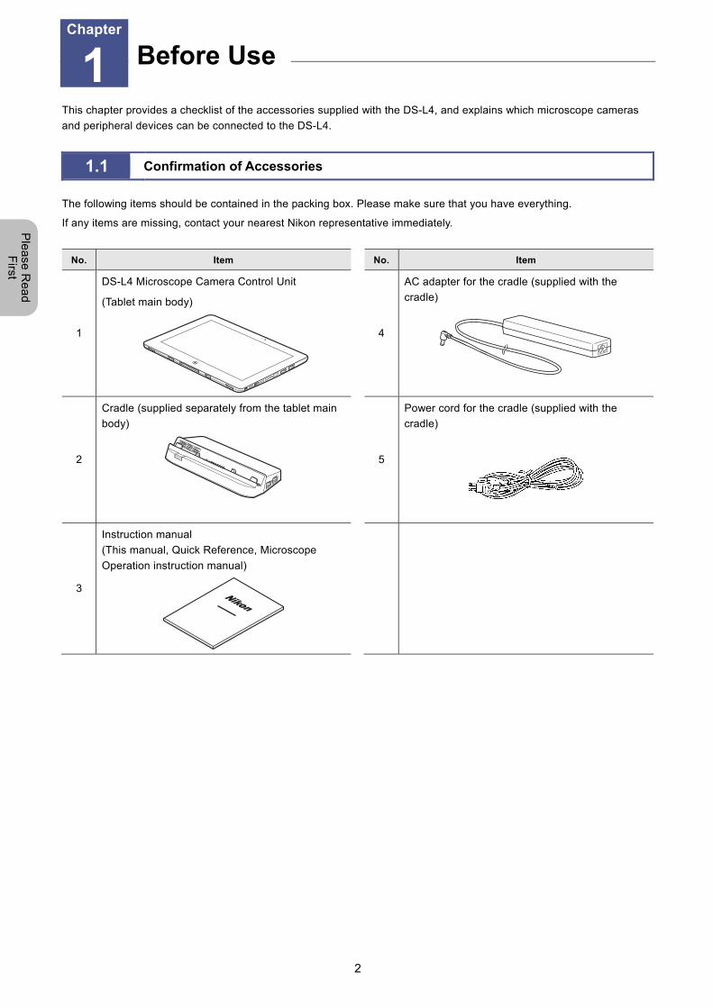
1.1 Confirmation of Accessories
The following items should be contained in the packing box. Please make sure that you have everything.
If any items are missing, contact your nearest Nikon representative immediately.
No. Item No. Item
1
DS-L4 Microscope Camera Control Unit
(Tablet main body)
4
AC adapter for the cradle (supplied with the
cradle)
2
Cradle (supplied separately from the tablet main
body)
5
Power cord for the cradle (supplied with the
cradle)
3
Instruction manual
(This manual, Quick Reference, Microscope
Operation instruction manual)
Before Use Chapter
1
Chapter 1 Before Use
3
Ple
ase
Re
ad
F
irst
1.2 Microscope Cameras Supported by the DS-L4
The following models of microscope cameras can be connected to the DS-L4.
The characteristics of the microscope camera differ depending on the model. Before using a camera, confirm that it is a
supported model.
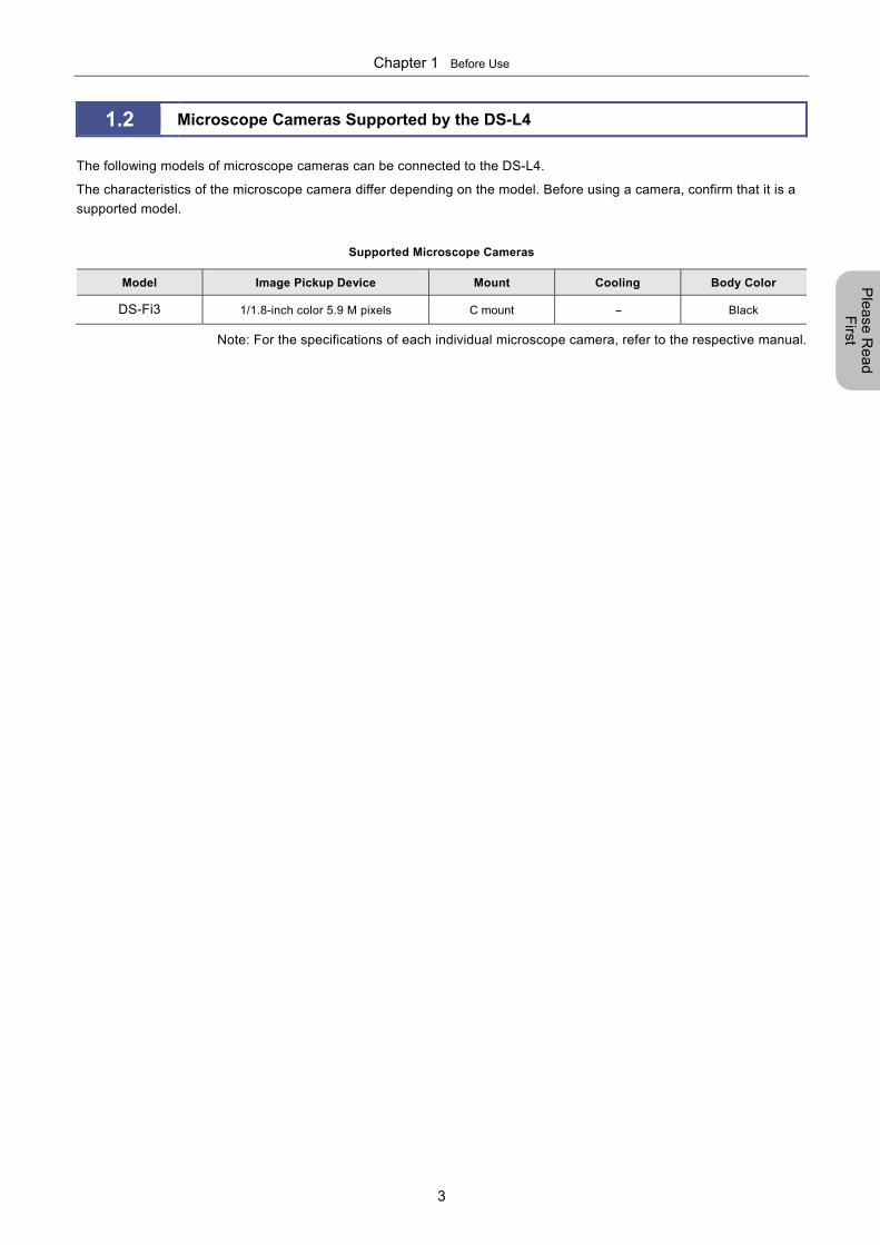
Supported Microscope Cameras
Model Image Pickup Device Mount Cooling Body Color
DS-Fi3 1/1.8-inch color 5.9 M pixels C mount -- Black
Note: For the specifications of each individual microscope camera, refer to the respective manual.
Chapter 1 Before Use
4
Ple
ase
Re
ad
F
irst
1.3 Peripheral Devices That Can Be Used
The following peripheral devices (sold separately) can be used with the DS-L4:
(1) External display
The DS-L4 has a built-in 10.1-inch wide LCD display with a resolution of 1920 x 1200 pixels (WUXGA). An external display
can be used for larger image observation.
The display to be used must be a PC display supporting an output resolution of 1920 x 1200 pixels (WUXGA).
The cradle of the DS-L4 has DisplayPort and analog display connectors for video output. A supported external display can
be connected to the DS-L4 via the cradle. To connect a digital-output display, use a DisplayPort cable. To connect an
analog RGB display, use an analog RGB (D-sub 15-pin) cable.
(2) MicroSD card
Commercially available microSD cards can be used as image storage media.
Please use a model whose operation is verified by Nikon. Not every microSD card is compatible with the DS-L4.
(3) USB memory drive
USB memory drives can be used as image storage media.
Please use a model whose operation is verified by Nikon. Not every USB memory drive is compatible with the DS-L4.
(4) USB mouse
A connected USB mouse can be used to perform operations equivalent to those of the touch panel.
For operation of menus on an external display, a mouse is required.
Use mouse operation for adding lines and comments to images (Annotation function), and measuring lengths and angles
on the screen (Measurement function).
Please use a model whose operation is verified by Nikon. Not every USB mouse is compatible with the DS-L4.
(5) USB keyboard
A connected USB keyboard can be used to directly enter values, comments, and other information.
Please use a USB keyboard whose operation is verified by Nikon. Not every USB keyboard is compatible with the DS-L4.
(6) USB hub
You will need a USB hub to connect a USB drive, USB mouse, USB keyboard, and other USB devices at the same time.
Please use a model whose operation is verified by Nikon. Not every USB hub is compatible with the DS-L4.
Note 1: The DS-L4 does not support cascading of hubs.
Note 2: If the USB keyboard you use has a USB hub, use the hub of the keyboard.
(7) Bluetooth mouse
A connected Bluetooth mouse can be used to perform operations equivalent to those of the touch panel.
For operation of menus on an external display, a mouse is required.
Use mouse operation for adding lines and comments to images (Annotation function), and measuring lengths and angles
on the screen (Measurement function).
Please use a model whose operation is verified by Nikon. Not every Bluetooth mouse is compatible with the DS-L4.
Chapter 1 Before Use
5
Ple
ase
Re
ad
F
irst
(8) Bluetooth keyboard
A connected Bluetooth keyboard can be used to directly enter values, comments, and other information.
Please use a model whose operation is verified by Nikon. Not every Bluetooth keyboard is compatible with the DS-L4.
(9) Network connection cable
A network connection cable is used for connecting the DS-L4 to a network (LAN). Use a 10 Base-T, 100 Base-TX, or 1000
Base-T cable (category 5e or higher).
With the DS-L4 connected to the network, you can save image files in a PC through the network and control the DS-L4
from a PC.
Network cables
Use a shielded cable that satisfies EMC standards.
When connecting the DS-L4 to a LAN, use a straight cable. When connecting the DS-L4 to a PC, use a
crossover cable.
Tightly connect the network cable
If the network cable is removed while the DS-L4 is being used, the DS-L4 may freeze for one minute or more. In such
a case, please wait for a while until the freeze state ends.
(10) Personal computer (PC)
A PC is necessary to process image data photographed by the DS-L4 or to control the DS-L4 remotely.
Chapter 2 Names of Parts and Their Functions
6
Ple
ase
Re
ad
F
irst
2 Names of Parts
This chapter shows the part names of the DS-L4.
2.1 DS-L4 Microscope Camera Control Unit
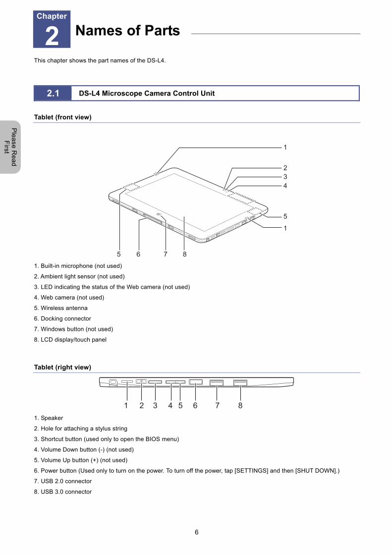
Tablet (front view)
1
234
5
1
5 6 7 8
1. Built-in microphone (not used)
2. Ambient light sensor (not used)
3. LED indicating the status of the Web camera (not used)
4. Web camera (not used)
5. Wireless antenna
6. Docking connector
7. Windows button (not used)
8. LCD display/touch panel
Tablet (right view)
1 2 3 4 5 6 7 8
1. Speaker
2. Hole for attaching a stylus string
3. Shortcut button (used only to open the BIOS menu)
4. Volume Down button (-) (not used)
5. Volume Up button (+) (not used)
6. Power button (Used only to turn on the power. To turn off the power, tap [SETTINGS] and then [SHUT DOWN].)
7. USB 2.0 connector
8. USB 3.0 connector
Names of Parts Chapter
2
Chapter 2 Names of Parts and Their Functions
7
Ple
ase
Re
ad
F
irst
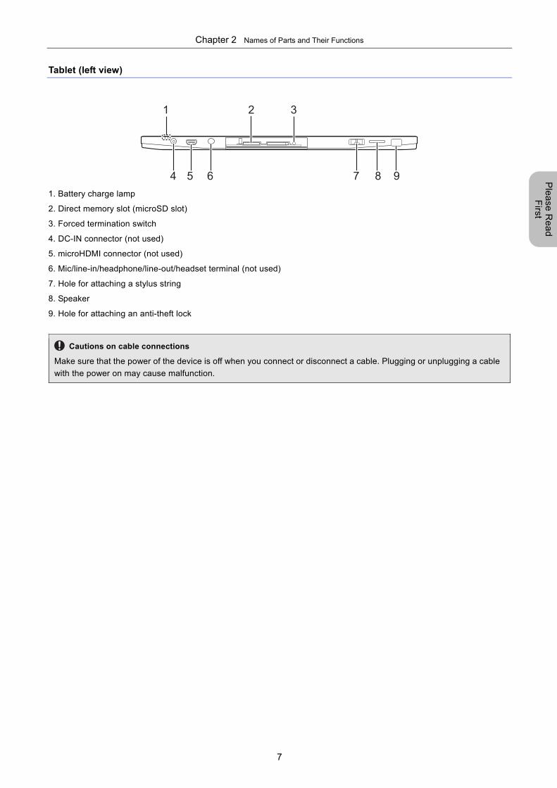
Tablet (left view)
1 2 3
4 65 7 8 9
1. Battery charge lamp
2. Direct memory slot (microSD slot)
3. Forced termination switch
4. DC-IN connector (not used)
5. microHDMI connector (not used)
6. Mic/line-in/headphone/line-out/headset terminal (not used)
7. Hole for attaching a stylus string
8. Speaker
9. Hole for attaching an anti-theft lock
Cautions on cable connections
Make sure that the power of the device is off when you connect or disconnect a cable. Plugging or unplugging a cable
with the power on may cause malfunction.
Chapter 2 Names of Parts and Their Functions
8
Ple
ase
Re
ad
F
irst
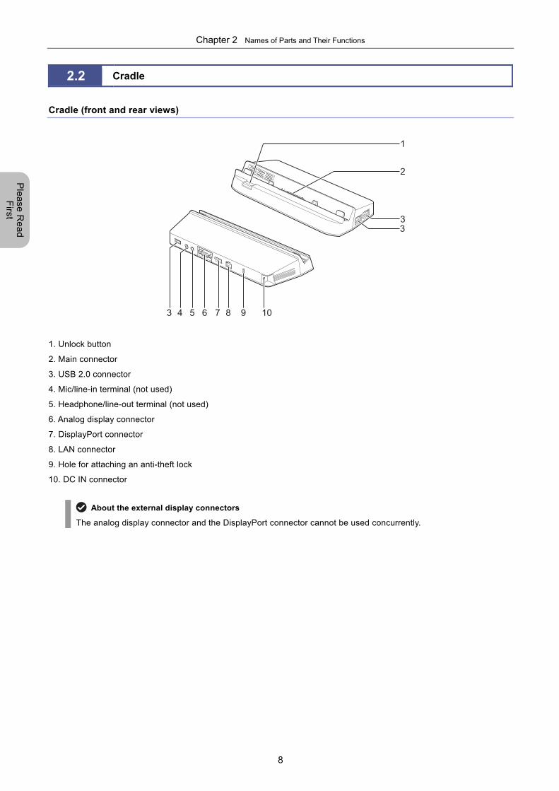
2.2 Cradle
Cradle (front and rear views)
3 4 5 6 7 8 9 10
1
2
33
1. Unlock button
2. Main connector
3. USB 2.0 connector
4. Mic/line-in terminal (not used)
5. Headphone/line-out terminal (not used)
6. Analog display connector
7. DisplayPort connector
8. LAN connector
9. Hole for attaching an anti-theft lock
10. DC IN connector
About the external display connectors
The analog display connector and the DisplayPort connector cannot be used concurrently.
Chapter 3 Installation and Connection
9
Ple
ase
Re
ad
F
irst
3 Installation and Connection
This chapter explains how to install and connect the DS-L4 and a microscope camera.
3.1 Installing the DS-L4
Cautions on installation
When you install the DS-L4, allow at least 10 cm between it and other objects for adequate heat dissipation.
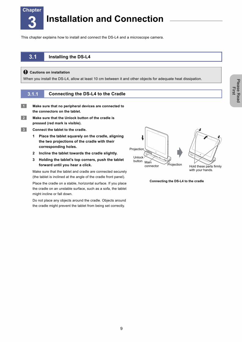
3.1.1 Connecting the DS-L4 to the Cradle
1 Make sure that no peripheral devices are connected to
the connectors on the tablet.
2 Make sure that the Unlock button of the cradle is
pressed (red mark is visible).
3 Connect the tablet to the cradle.
1 Place the tablet squarely on the cradle, aligning
the two projections of the cradle with their
corresponding holes.
2 Incline the tablet towards the cradle slightly.
3 Holding the tablet's top corners, push the tablet
forward until you hear a click.
Make sure that the tablet and cradle are connected securely
(the tablet is inclined at the angle of the cradle front panel).
Place the cradle on a stable, horizontal surface. If you place
the cradle on an unstable surface, such as a sofa, the tablet
might incline or fall down.
Do not place any objects around the cradle. Objects around
the cradle might prevent the tablet from being set correctly.
Connecting the DS-L4 to the cradle
Installation and Connection Chapter
3
Hold these parts firmly with your hands.
Main connector Projection
Projection
Unlock button
Chapter 3 Installation and Connection
10
Ple
ase
Re
ad
F
irst
3.2 Connecting the DS-L4 and Peripheral Devices
Always turn the power off before plugging or unplugging cables.
Confirm that the power of devices is turned off before plugging or unplugging cables.
Connecting a cable when the power is on may cause electric shock, or malfunction or failure of the device.
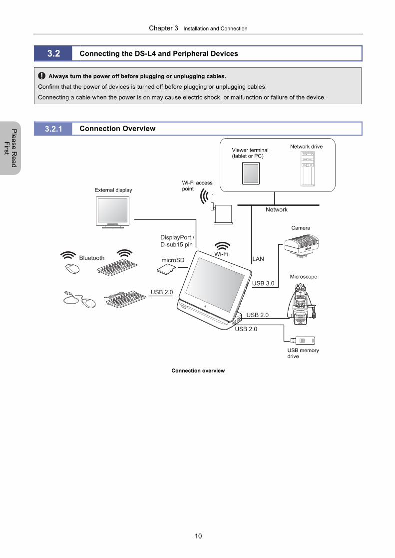
3.2.1 Connection Overview
Bluetooth
USB 2.0
microSD
DisplayPort / D-sub15 pin
USB 2.0
USB 2.0
USB 3.0
Wi-FiLAN
Network
Connection overview
USB memory drive
Viewer terminal (tablet or PC)
Network drive
External display
Camera
Microscope
Wi-Fi access point
Chapter 3 Installation and Connection
11
Ple
ase
Re
ad
F
irst
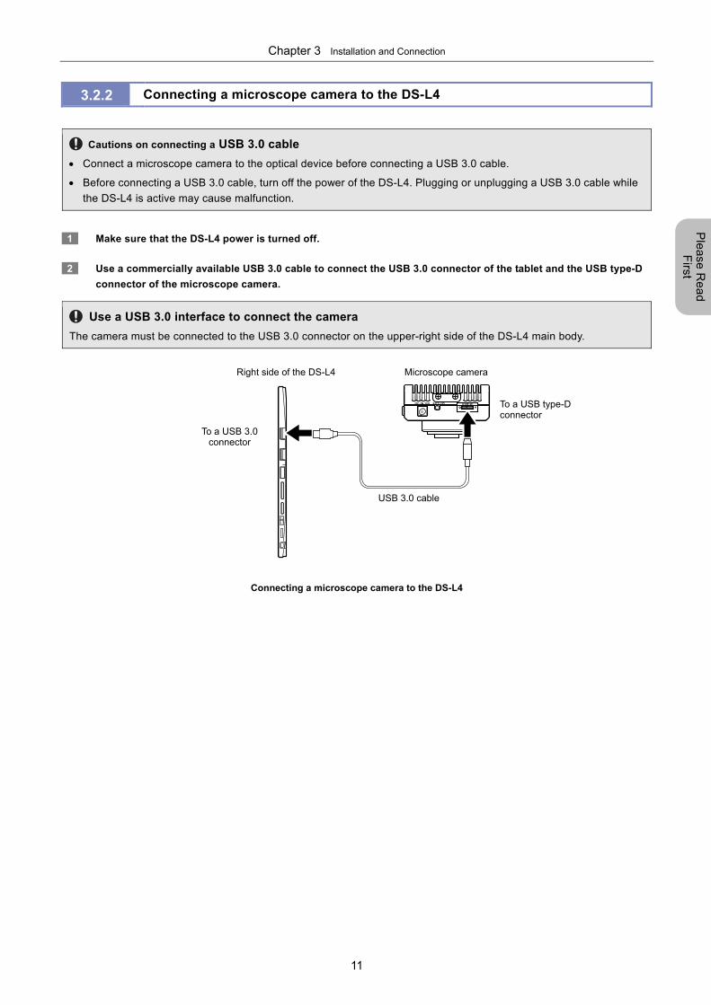
3.2.2 Connecting a microscope camera to the DS-L4
Cautions on connecting a USB 3.0 cable
Connect a microscope camera to the optical device before connecting a USB 3.0 cable.
Before connecting a USB 3.0 cable, turn off the power of the DS-L4. Plugging or unplugging a USB 3.0 cable while
the DS-L4 is active may cause malfunction.
1 Make sure that the DS-L4 power is turned off.
2 Use a commercially available USB 3.0 cable to connect the USB 3.0 connector of the tablet and the USB type-D
connector of the microscope camera.
Use a USB 3.0 interface to connect the camera
The camera must be connected to the USB 3.0 connector on the upper-right side of the DS-L4 main body.
Connecting a microscope camera to the DS-L4
Microscope camera Right side of the DS-L4
USB 3.0 cable
To a USB type-Dconnector
To a USB 3.0 connector
Chapter 3 Installation and Connection
12
Ple
ase
Re
ad
F
irst
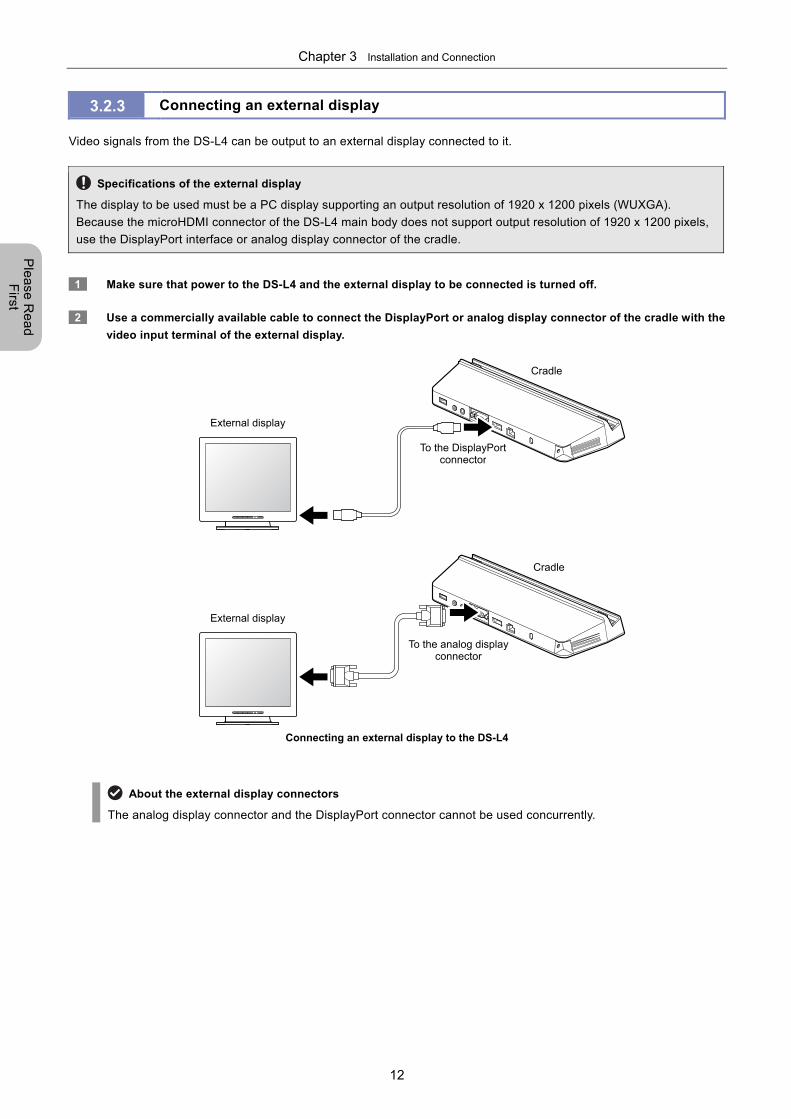
3.2.3 Connecting an external display
Video signals from the DS-L4 can be output to an external display connected to it.
Specifications of the external display
The display to be used must be a PC display supporting an output resolution of 1920 x 1200 pixels (WUXGA).
Because the microHDMI connector of the DS-L4 main body does not support output resolution of 1920 x 1200 pixels,
use the DisplayPort interface or analog display connector of the cradle.
1 Make sure that power to the DS-L4 and the external display to be connected is turned off.
2 Use a commercially available cable to connect the DisplayPort or analog display connector of the cradle with the
video input terminal of the external display.
Connecting an external display to the DS-L4
About the external display connectors
The analog display connector and the DisplayPort connector cannot be used concurrently.
External display
To the DisplayPort connector
To the analog display connector
External display
Cradle
Cradle
Chapter 3 Installation and Connection
13
Ple
ase
Re
ad
F
irst
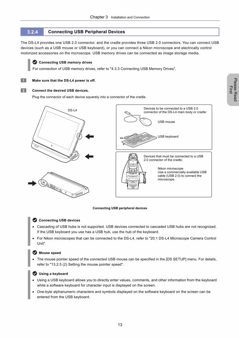
3.2.4 Connecting USB Peripheral Devices
The DS-L4 provides one USB 2.0 connector, and the cradle provides three USB 2.0 connectors. You can connect USB
devices (such as a USB mouse or USB keyboard), or you can connect a Nikon microscope and electrically control
motorized accessories on the microscope. USB memory drives can be connected as image storage media.
Connecting USB memory drives
For connection of USB memory drives, refer to "4.3.3 Connecting USB Memory Drives".
1 Make sure that the DS-L4 power is off.
2 Connect the desired USB devices.
Plug the connector of each device squarely into a connector of the cradle.
Connecting USB peripheral devices
Connecting USB devices
Cascading of USB hubs is not supported. USB devices connected to cascaded USB hubs are not recognized.
If the USB keyboard you use has a USB hub, use the hub of the keyboard.
For Nikon microscopes that can be connected to the DS-L4, refer to "20.1 DS-L4 Microscope Camera Control
Unit".
Mouse speed
The mouse pointer speed of the connected USB mouse can be specified in the [DS SETUP] menu. For details,
refer to "13.2.5 (2) Setting the mouse pointer speed".
Using a keyboard
Using a USB keyboard allows you to directly enter values, comments, and other information from the keyboard
while a software keyboard for character input is displayed on the screen.
One-byte alphanumeric characters and symbols displayed on the software keyboard on the screen can be
entered from the USB keyboard.
DS-L4
Nikon microscope Use a commercially available USBcable (USB 2.0) to connect the microscope.
USB mouse
USB keyboard
Devices to be connected to a USB 2.0 connector of the DS-L4 main body or cradle:
Devices that must be connected to a USB 2.0 connector of the cradle:
Chapter 3 Installation and Connection
14
Ple
ase
Re
ad
F
irst
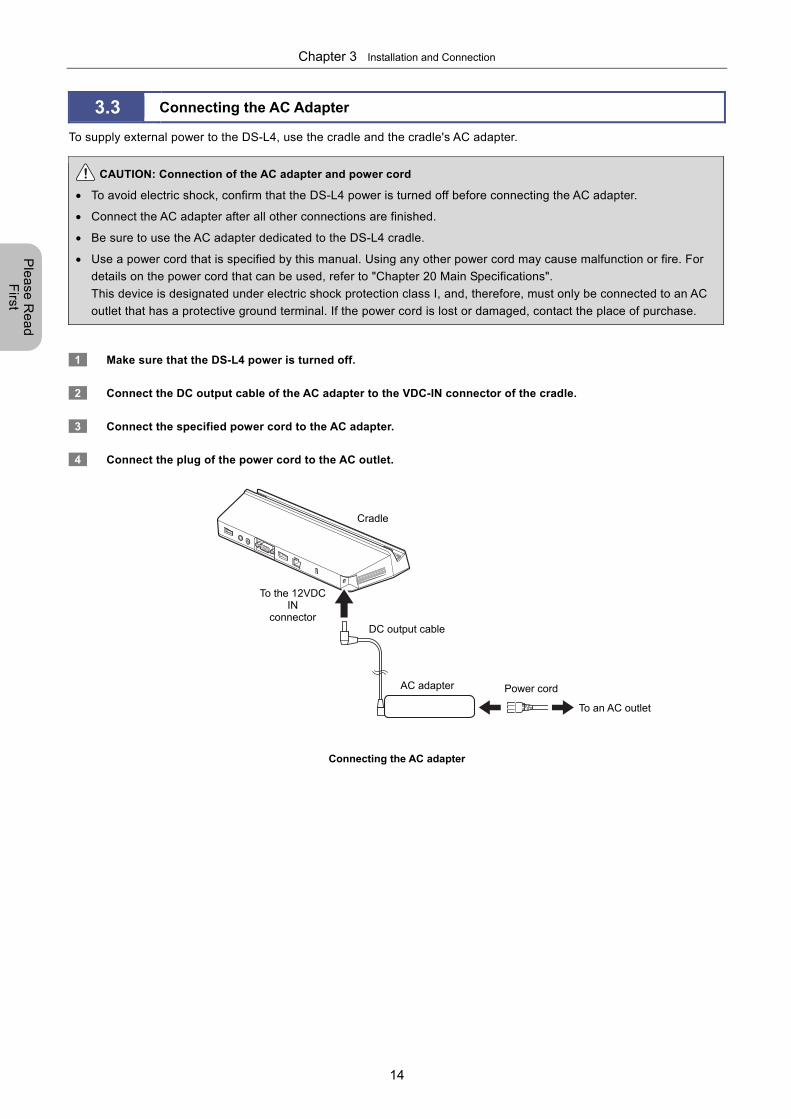
3.3 Connecting the AC Adapter
To supply external power to the DS-L4, use the cradle and the cradle's AC adapter.
CAUTION: Connection of the AC adapter and power cord
To avoid electric shock, confirm that the DS-L4 power is turned off before connecting the AC adapter.
Connect the AC adapter after all other connections are finished.
Be sure to use the AC adapter dedicated to the DS-L4 cradle.
Use a power cord that is specified by this manual. Using any other power cord may cause malfunction or fire. For
details on the power cord that can be used, refer to "Chapter 20 Main Specifications".
This device is designated under electric shock protection class I, and, therefore, must only be connected to an AC
outlet that has a protective ground terminal. If the power cord is lost or damaged, contact the place of purchase.
1 Make sure that the DS-L4 power is turned off.
2 Connect the DC output cable of the AC adapter to the VDC-IN connector of the cradle.
3 Connect the specified power cord to the AC adapter.
4 Connect the plug of the power cord to the AC outlet.
Connecting the AC adapter
DC output cable
To the 12VDC IN
connector
AC adapter Power cord
To an AC outlet
Cradle
Chapter 4 Preparing for Use
15
Ple
ase
Re
ad
F
irst
4 Preparing for Use
This chapter explains the accessory preparations for using the DS-L4 for observation or photographing.
4.1 Starting/Closing DS-L4
CAUTION: Power supply for the DS-L4
When you turn off the DS-L4 power, in the login screen, LIVE menu, or VIEW menu, be sure to tap [SETTINGS],
and then [SHUT DOWN].
Use only a 100 to 240 VAC (50 to 60 Hz) power supply, and to which the AC adapter is directly connected.
Be sure to use the specified power cord.
Be sure to use the specified AC adapter.
4.1.1 Starting the DS-L4
The following describes the procedure for starting the DS-L4.
When using the microscope control function
When you connect a Nikon microscope to the DS-L4 and use the microscope control function of the DS-L4,
switch on the microscope before switching on the DS-L4. For details on how to switch on the microscope, refer to
the manual of the microscope.
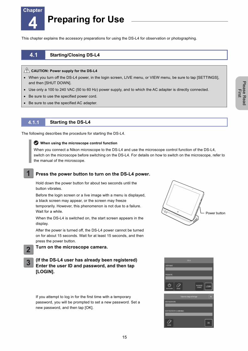
1 Press the power button to turn on the DS-L4 power.
Hold down the power button for about two seconds until the
button vibrates.
Before the login screen or a live image with a menu is displayed,
a black screen may appear, or the screen may freeze
temporarily. However, this phenomenon is not due to a failure.
Wait for a while.
When the DS-L4 is switched on, the start screen appears in the
display.
After the power is turned off, the DS-L4 power cannot be turned
on for about 15 seconds. Wait for at least 15 seconds, and then
press the power button.
2
Turn on the microscope camera.
3
(If the DS-L4 user has already been registered) Enter the user ID and password, and then tap [LOGIN].
If you attempt to log in for the first time with a temporary
password, you will be prompted to set a new password. Set a
new password, and then tap [OK].
Preparing for Use Chapter
4
Power button
Chapter 4 Preparing for Use
16
Ple
ase
Re
ad
F
irst
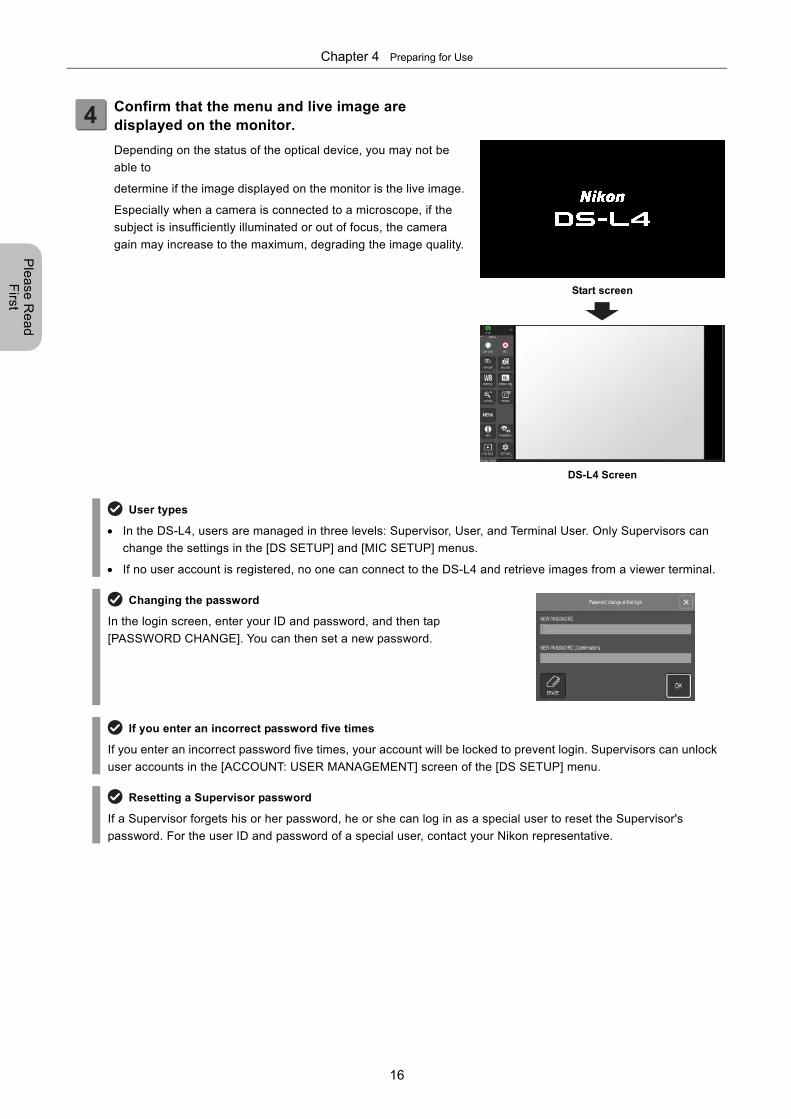
4
Confirm that the menu and live image are displayed on the monitor.
Depending on the status of the optical device, you may not be
able to
determine if the image displayed on the monitor is the live image.
Especially when a camera is connected to a microscope, if the
subject is insufficiently illuminated or out of focus, the camera
gain may increase to the maximum, degrading the image quality.
Start screen
DS-L4 Screen
User types
In the DS-L4, users are managed in three levels: Supervisor, User, and Terminal User. Only Supervisors can
change the settings in the [DS SETUP] and [MIC SETUP] menus.
If no user account is registered, no one can connect to the DS-L4 and retrieve images from a viewer terminal.
Changing the password
In the login screen, enter your ID and password, and then tap
[PASSWORD CHANGE]. You can then set a new password.
If you enter an incorrect password five times
If you enter an incorrect password five times, your account will be locked to prevent login. Supervisors can unlock
user accounts in the [ACCOUNT: USER MANAGEMENT] screen of the [DS SETUP] menu.
Resetting a Supervisor password
If a Supervisor forgets his or her password, he or she can log in as a special user to reset the Supervisor's
password. For the user ID and password of a special user, contact your Nikon representative.
Chapter 4 Preparing for Use
17
Ple
ase
Re
ad
F
irst
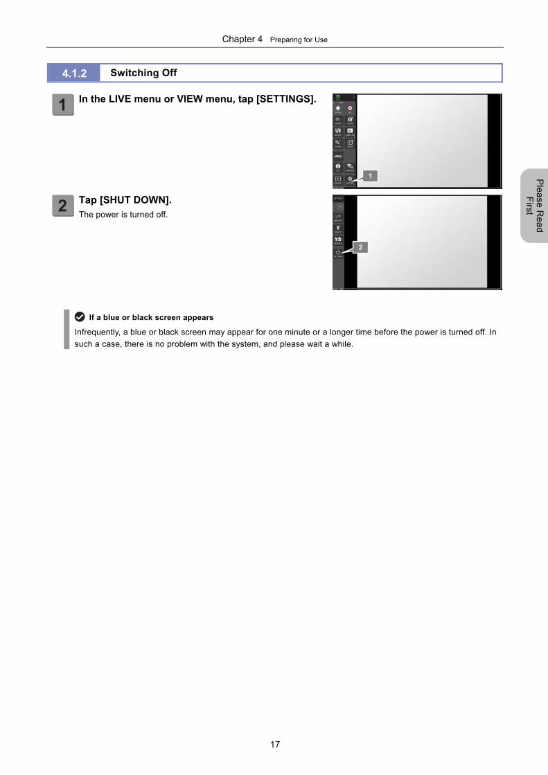
4.1.2 Switching Off
1
In the LIVE menu or VIEW menu, tap [SETTINGS].
2
Tap [SHUT DOWN]. The power is turned off.
If a blue or black screen appears
Infrequently, a blue or black screen may appear for one minute or a longer time before the power is turned off. In
such a case, there is no problem with the system, and please wait a while.
1
2
Chapter 4 Preparing for Use
18
Ple
ase
Re
ad
F
irst
4.2 Setting the Display Language
The minimum necessary settings for operating the DS-L4 are explained here.
Note: For other initial setting items, refer to "Chapter 13 Changing Settings".
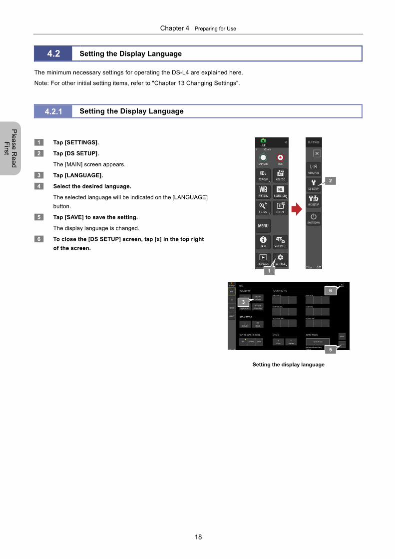
4.2.1 Setting the Display Language
1 Tap [SETTINGS].
2 Tap [DS SETUP].
The [MAIN] screen appears.
3 Tap [LANGUAGE].
4 Select the desired language.
The selected language will be indicated on the [LANGUAGE]
button.
5 Tap [SAVE] to save the setting.
The display language is changed.
6 To close the [DS SETUP] screen, tap [x] in the top right
of the screen.
Setting the display language
3
5
6
1
2
Chapter 4 Preparing for Use
19
Ple
ase
Re
ad
F
irst
4.3 Preparing Recording Media
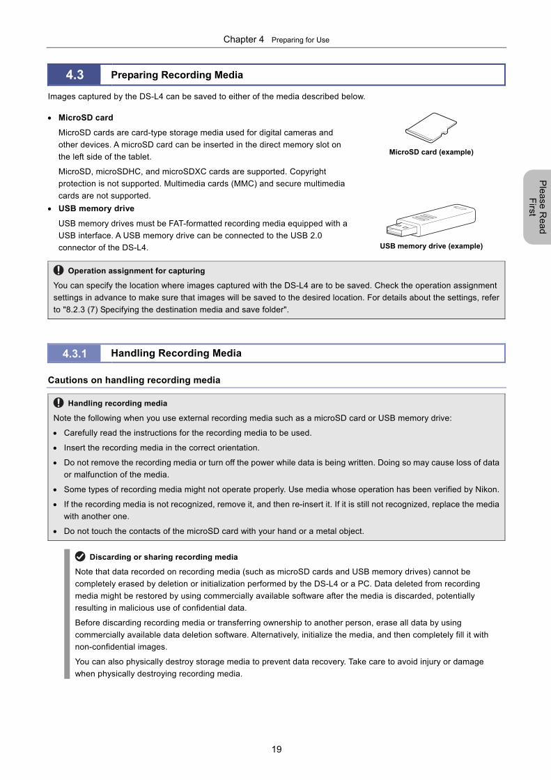
Images captured by the DS-L4 can be saved to either of the media described below.
MicroSD card
MicroSD cards are card-type storage media used for digital cameras and
other devices. A microSD card can be inserted in the direct memory slot on
the left side of the tablet.
MicroSD, microSDHC, and microSDXC cards are supported. Copyright
protection is not supported. Multimedia cards (MMC) and secure multimedia
cards are not supported.
MicroSD card (example)
USB memory drive
USB memory drives must be FAT-formatted recording media equipped with a
USB interface. A USB memory drive can be connected to the USB 2.0
connector of the DS-L4.
USB memory drive (example)
Operation assignment for capturing
You can specify the location where images captured with the DS-L4 are to be saved. Check the operation assignment
settings in advance to make sure that images will be saved to the desired location. For details about the settings, refer
to "8.2.3 (7) Specifying the destination media and save folder".
4.3.1 Handling Recording Media
Cautions on handling recording media
Handling recording media
Note the following when you use external recording media such as a microSD card or USB memory drive:
Carefully read the instructions for the recording media to be used.
Insert the recording media in the correct orientation.
Do not remove the recording media or turn off the power while data is being written. Doing so may cause loss of data
or malfunction of the media.
Some types of recording media might not operate properly. Use media whose operation has been verified by Nikon.
If the recording media is not recognized, remove it, and then re-insert it. If it is still not recognized, replace the media
with another one.
Do not touch the contacts of the microSD card with your hand or a metal object.
Discarding or sharing recording media
Note that data recorded on recording media (such as microSD cards and USB memory drives) cannot be
completely erased by deletion or initialization performed by the DS-L4 or a PC. Data deleted from recording
media might be restored by using commercially available software after the media is discarded, potentially
resulting in malicious use of confidential data.
Before discarding recording media or transferring ownership to another person, erase all data by using
commercially available data deletion software. Alternatively, initialize the media, and then completely fill it with
non-confidential images.
You can also physically destroy storage media to prevent data recovery. Take care to avoid injury or damage
when physically destroying recording media.
Chapter 4 Preparing for Use
20
Ple
ase
Re
ad
F
irst
Initializing recording media
Before you can use a microSD card, USB memory drive, or other recording media with the DS-L4, you must initialize
(format) the media by using a PC.
When initializing recording media, you can specify a volume label, which is displayed in the screen for setting image save
destinations, and can be used to identify the media. We recommend that you specify a volume label when initializing
recording media. For recording media devices for which no volume labels are set, strings EXT1, EXT2, EXT3, ... are
displayed.
Backing up data
Note that, initializing storage media renders any data saved on the media unusable. Back up any important data (to a
PC, etc.) stored on the media before initializing it.
Setting the image storage and playback folders
The DS-L4 allows you to connect multiple recording media devices, and to switch the storage folder and playback folder.
Before you start capturing images, you must specify the recording media and folder as the storage location for the
captured images.
For details about setting the image storage location, refer to "8.2.3 (7) Specifying the destination media and save folder".
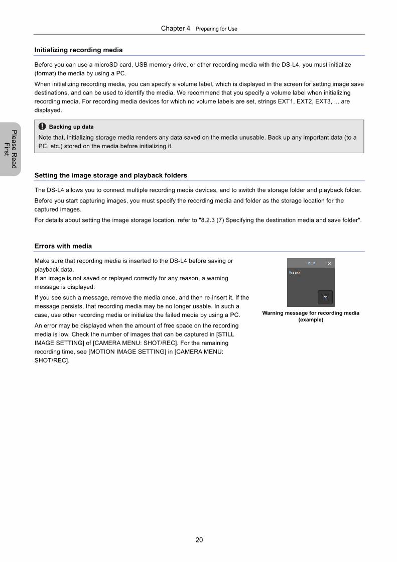
Errors with media
Make sure that recording media is inserted to the DS-L4 before saving or
playback data.
If an image is not saved or replayed correctly for any reason, a warning
message is displayed.
If you see such a message, remove the media once, and then re-insert it. If the
message persists, that recording media may be no longer usable. In such a
case, use other recording media or initialize the failed media by using a PC.
An error may be displayed when the amount of free space on the recording
media is low. Check the number of images that can be captured in [STILL
IMAGE SETTING] of [CAMERA MENU: SHOT/REC]. For the remaining
recording time, see [MOTION IMAGE SETTING] in [CAMERA MENU:
SHOT/REC].
Warning message for recording media
(example)
Chapter 4 Preparing for Use
21
Ple
ase
Re
ad
F
irst
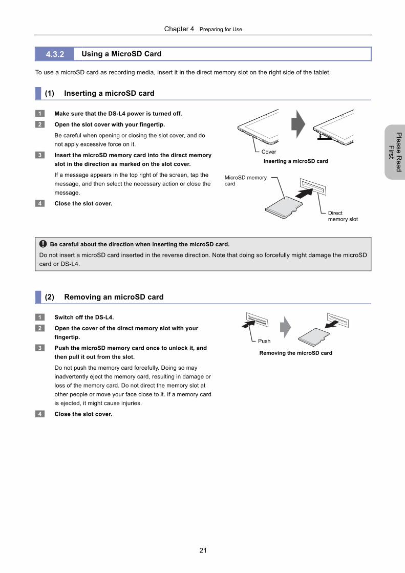
4.3.2 Using a MicroSD Card
To use a microSD card as recording media, insert it in the direct memory slot on the right side of the tablet.
(1) Inserting a microSD card
1 Make sure that the DS-L4 power is turned off.
2 Open the slot cover with your fingertip.
Be careful when opening or closing the slot cover, and do
not apply excessive force on it.
3 Insert the microSD memory card into the direct memory
slot in the direction as marked on the slot cover.
If a message appears in the top right of the screen, tap the
message, and then select the necessary action or close the
message.
4 Close the slot cover.
Inserting a microSD card
Be careful about the direction when inserting the microSD card.
Do not insert a microSD card inserted in the reverse direction. Note that doing so forcefully might damage the microSD
card or DS-L4.
(2) Removing an microSD card
1 Switch off the DS-L4.
2 Open the cover of the direct memory slot with your
fingertip.
3 Push the microSD memory card once to unlock it, and
then pull it out from the slot.
Do not push the memory card forcefully. Doing so may
inadvertently eject the memory card, resulting in damage or
loss of the memory card. Do not direct the memory slot at
other people or move your face close to it. If a memory card
is ejected, it might cause injuries.
4 Close the slot cover.
Removing the microSD card
Direct memory slot
Cover
MicroSD memory card
Push
Chapter 4 Preparing for Use
22
Ple
ase
Re
ad
F
irst
4.3.3 Connecting USB Memory Drives
Multiple USB memory drives can be connected to the DS-L4, and used for storing or replaying images.
You can connect any type of USB 2.0-compatible FAT-formatted storage device (including a USB memory drive).
Do not remove a USB memory drive while it is being accessed.
Even while the DS-L4 is switched on, you can connect or disconnect a USB memory drive.
Note that the access lamp of a USB memory drive lights up when the drive is being accessed (storing, deleting, or
reading data). While the access lamp is lit, never remove a USB memory drive or switch off the DS-L4. Doing so might
result in lost data or damage to the USB drive.
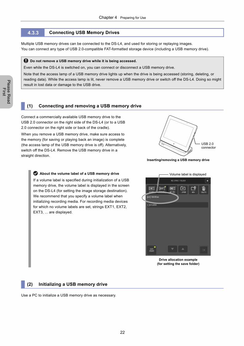
(1) Connecting and removing a USB memory drive
Connect a commercially available USB memory drive to the
USB 2.0 connector on the right side of the DS-L4 (or to a USB
2.0 connector on the right side or back of the cradle).
When you remove a USB memory drive, make sure access to
the memory (for saving or playing back an image) is complete
(the access lamp of the USB memory drive is off). Alternatively,
switch off the DS-L4. Remove the USB memory drive in a
straight direction.
Inserting/removing a USB memory drive
About the volume label of a USB memory drive
If a volume label is specified during initialization of a USB
memory drive, the volume label is displayed in the screen
on the DS-L4 (for setting the image storage destination).
We recommend that you specify a volume label when
initializing recording media. For recording media devices
for which no volume labels are set, strings EXT1, EXT2,
EXT3, ... are displayed.
Drive allocation example
(for setting the save folder)
(2) Initializing a USB memory drive
Use a PC to initialize a USB memory drive as necessary.
USB 2.0 connector
Volume label is displayed
Chapter 5 Using Menus
23
Ple
ase
Re
ad
F
irst
5 Using Menus
This chapter explains how to use the menus of the DS-L4.
5.1 Navigating through Screen Menus
This section explains the configuration of the DS-L4 operation menus, and includes some basics on how to use them.
5.1.1 Menu Configuration and Method of Displaying Menus
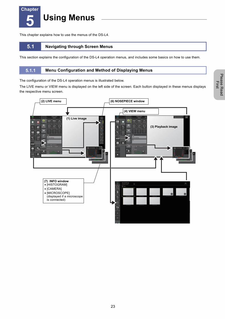
The configuration of the DS-L4 operation menus is illustrated below.
The LIVE menu or VIEW menu is displayed on the left side of the screen. Each button displayed in these menus displays
the respective menu screen.
(1) Live image
(7) INFO window [HISTOGRAM] [CAMERA] [MICROSCOPE]
(displayed if a microscope is connected)
Using Menus Chapter
5
(3) Playback image
(2) LIVE menu
(4) VIEW menu
(6) NOSEPIECE window
Chapter 5 Using Menus
24
Ple
ase
Re
ad
F
irst
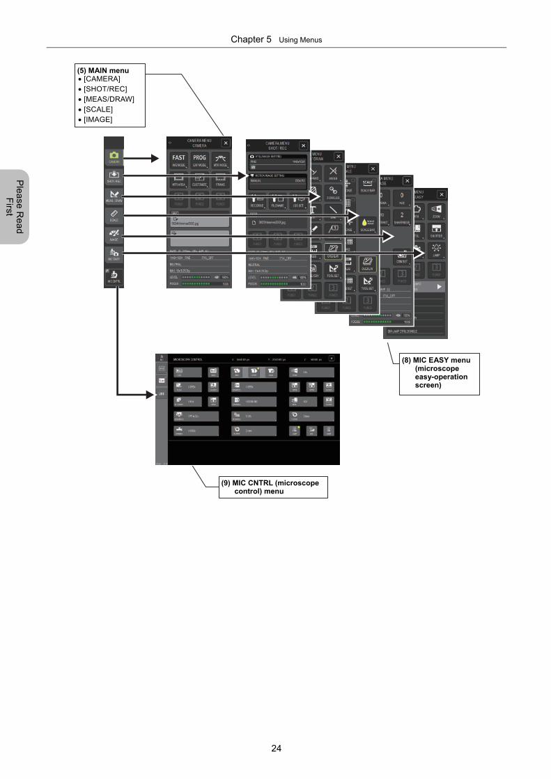
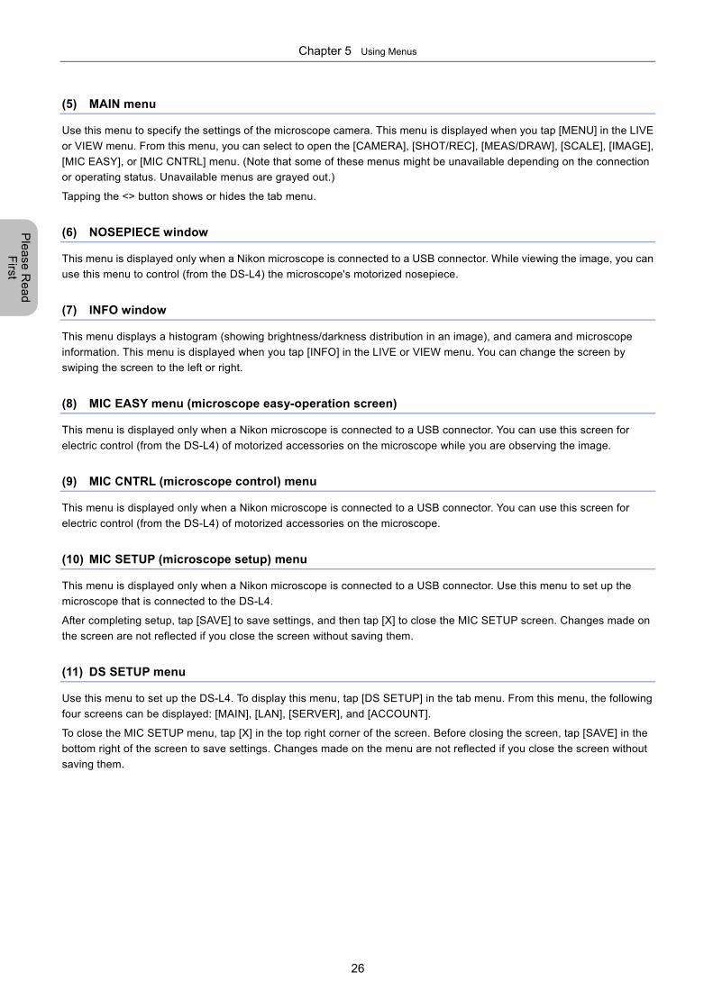
(5) MAIN menu [CAMERA] [SHOT/REC] [MEAS/DRAW] [SCALE] [IMAGE]
(8) MIC EASY menu (microscope easy-operation screen)
(9) MIC CNTRL (microscope control) menu
Chapter 5 Using Menus
25
Ple
ase
Re
ad
F
irst
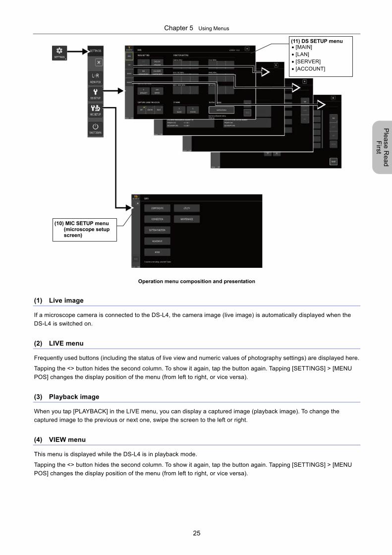
Operation menu composition and presentation
(1) Live image
If a microscope camera is connected to the DS-L4, the camera image (live image) is automatically displayed when the
DS-L4 is switched on.
(2) LIVE menu
Frequently used buttons (including the status of live view and numeric values of photography settings) are displayed here.
Tapping the <> button hides the second column. To show it again, tap the button again. Tapping [SETTINGS] > [MENU
POS] changes the display position of the menu (from left to right, or vice versa).
(3) Playback image
When you tap [PLAYBACK] in the LIVE menu, you can display a captured image (playback image). To change the
captured image to the previous or next one, swipe the screen to the left or right.
(4) VIEW menu
This menu is displayed while the DS-L4 is in playback mode.
Tapping the <> button hides the second column. To show it again, tap the button again. Tapping [SETTINGS] > [MENU
POS] changes the display position of the menu (from left to right, or vice versa).
(11) DS SETUP menu [MAIN] [LAN] [SERVER] [ACCOUNT]
(10) MIC SETUP menu (microscope setup screen)
Chapter 5 Using Menus
26
Ple
ase
Re
ad
F
irst
(5) MAIN menu
Use this menu to specify the settings of the microscope camera. This menu is displayed when you tap [MENU] in the LIVE
or VIEW menu. From this menu, you can select to open the [CAMERA], [SHOT/REC], [MEAS/DRAW], [SCALE], [IMAGE],
[MIC EASY], or [MIC CNTRL] menu. (Note that some of these menus might be unavailable depending on the connection
or operating status. Unavailable menus are grayed out.)
Tapping the <> button shows or hides the tab menu.
(6) NOSEPIECE window
This menu is displayed only when a Nikon microscope is connected to a USB connector. While viewing the image, you can
use this menu to control (from the DS-L4) the microscope's motorized nosepiece.
(7) INFO window
This menu displays a histogram (showing brightness/darkness distribution in an image), and camera and microscope
information. This menu is displayed when you tap [INFO] in the LIVE or VIEW menu. You can change the screen by
swiping the screen to the left or right.
(8) MIC EASY menu (microscope easy-operation screen)
This menu is displayed only when a Nikon microscope is connected to a USB connector. You can use this screen for
electric control (from the DS-L4) of motorized accessories on the microscope while you are observing the image.
(9) MIC CNTRL (microscope control) menu
This menu is displayed only when a Nikon microscope is connected to a USB connector. You can use this screen for
electric control (from the DS-L4) of motorized accessories on the microscope.
(10) MIC SETUP (microscope setup) menu
This menu is displayed only when a Nikon microscope is connected to a USB connector. Use this menu to set up the
microscope that is connected to the DS-L4.
After completing setup, tap [SAVE] to save settings, and then tap [X] to close the MIC SETUP screen. Changes made on
the screen are not reflected if you close the screen without saving them.
(11) DS SETUP menu
Use this menu to set up the DS-L4. To display this menu, tap [DS SETUP] in the tab menu. From this menu, the following
four screens can be displayed: [MAIN], [LAN], [SERVER], and [ACCOUNT].
To close the MIC SETUP menu, tap [X] in the top right corner of the screen. Before closing the screen, tap [SAVE] in the
bottom right of the screen to save settings. Changes made on the menu are not reflected if you close the screen without
saving them.
Chapter 5 Using Menus
27
Ple
ase
Re
ad
F
irst
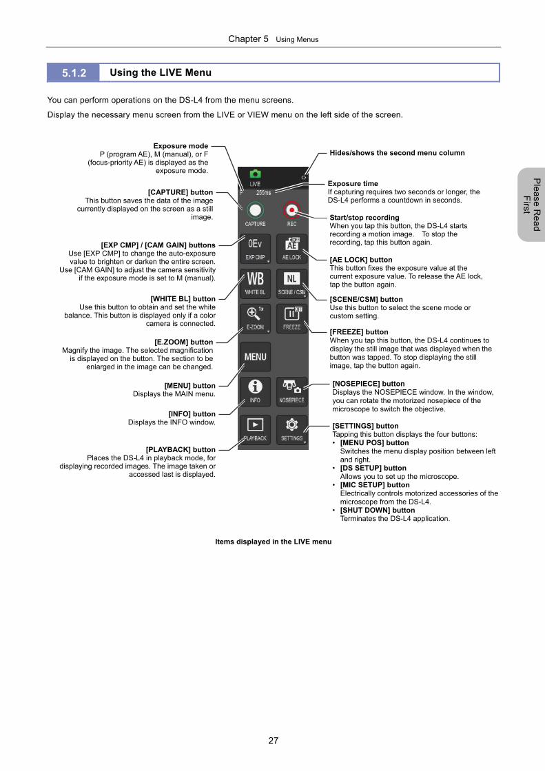
5.1.2 Using the LIVE Menu
You can perform operations on the DS-L4 from the menu screens.
Display the necessary menu screen from the LIVE or VIEW menu on the left side of the screen.
Items displayed in the LIVE menu
[MENU] buttonDisplays the MAIN menu.
[CAPTURE] buttonThis button saves the data of the image
currently displayed on the screen as a stillimage.
[E.ZOOM] buttonMagnify the image. The selected magnification
is displayed on the button. The section to beenlarged in the image can be changed.
[SCENE/CSM] buttonUse this button to select the scene mode or custom setting.
[EXP CMP] / [CAM GAIN] buttonsUse [EXP CMP] to change the auto-exposure value to brighten or darken the entire screen.
Use [CAM GAIN] to adjust the camera sensitivityif the exposure mode is set to M (manual).
[WHITE BL] buttonUse this button to obtain and set the white
balance. This button is displayed only if a colorcamera is connected.
[FREEZE] button When you tap this button, the DS-L4 continues to display the still image that was displayed when thebutton was tapped. To stop displaying the still image, tap the button again.
Exposure modeP (program AE), M (manual), or F
(focus-priority AE) is displayed as theexposure mode.
Exposure time If capturing requires two seconds or longer, the DS-L4 performs a countdown in seconds.
[INFO] buttonDisplays the INFO window.
[PLAYBACK] buttonPlaces the DS-L4 in playback mode, for
displaying recorded images. The image taken oraccessed last is displayed.
Start/stop recordingWhen you tap this button, the DS-L4 starts recording a motion image. To stop the recording, tap this button again.
[AE LOCK] buttonThis button fixes the exposure value at the current exposure value. To release the AE lock, tap the button again.
[NOSEPIECE] button Displays the NOSEPIECE window. In the window, you can rotate the motorized nosepiece of the microscope to switch the objective.
[SETTINGS] button Tapping this button displays the four buttons: • [MENU POS] button
Switches the menu display position between left and right.
• [DS SETUP] button Allows you to set up the microscope.
• [MIC SETUP] button Electrically controls motorized accessories of the microscope from the DS-L4.
• [SHUT DOWN] button Terminates the DS-L4 application.
Hides/shows the second menu column
Chapter 5 Using Menus
28
Ple
ase
Re
ad
F
irst
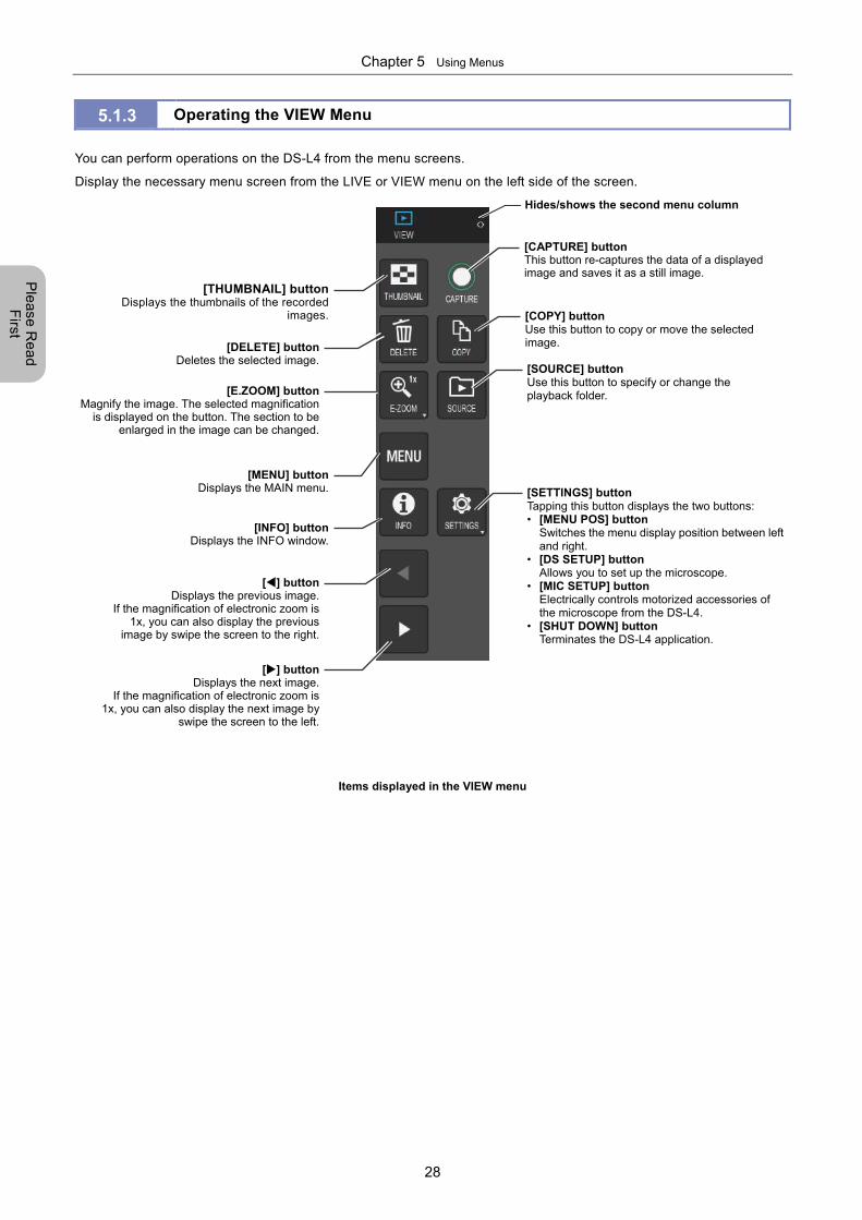
5.1.3 Operating the VIEW Menu
You can perform operations on the DS-L4 from the menu screens.
Display the necessary menu screen from the LIVE or VIEW menu on the left side of the screen.
Items displayed in the VIEW menu
[MENU] buttonDisplays the MAIN menu.
[CAPTURE] buttonThis button re-captures the data of a displayed image and saves it as a still image.
[E.ZOOM] buttonMagnify the image. The selected magnification
is displayed on the button. The section to be enlarged in the image can be changed.
[INFO] buttonDisplays the INFO window.
[DELETE] buttonDeletes the selected image.
[COPY] button Use this button to copy or move the selected image.
[SOURCE] button Use this button to specify or change the playback folder.
[THUMBNAIL] buttonDisplays the thumbnails of the recorded
images.
[] buttonDisplays the previous image.
If the magnification of electronic zoom is1x, you can also display the previous
image by swipe the screen to the right.
[] buttonDisplays the next image.
If the magnification of electronic zoom is1x, you can also display the next image by
swipe the screen to the left.
Hides/shows the second menu column
[SETTINGS] button Tapping this button displays the two buttons: • [MENU POS] button
Switches the menu display position between leftand right.
• [DS SETUP] button Allows you to set up the microscope.
• [MIC SETUP] button Electrically controls motorized accessories of the microscope from the DS-L4.
• [SHUT DOWN] button Terminates the DS-L4 application.
Chapter 5 Using Menus
29
Ple
ase
Re
ad
F
irst
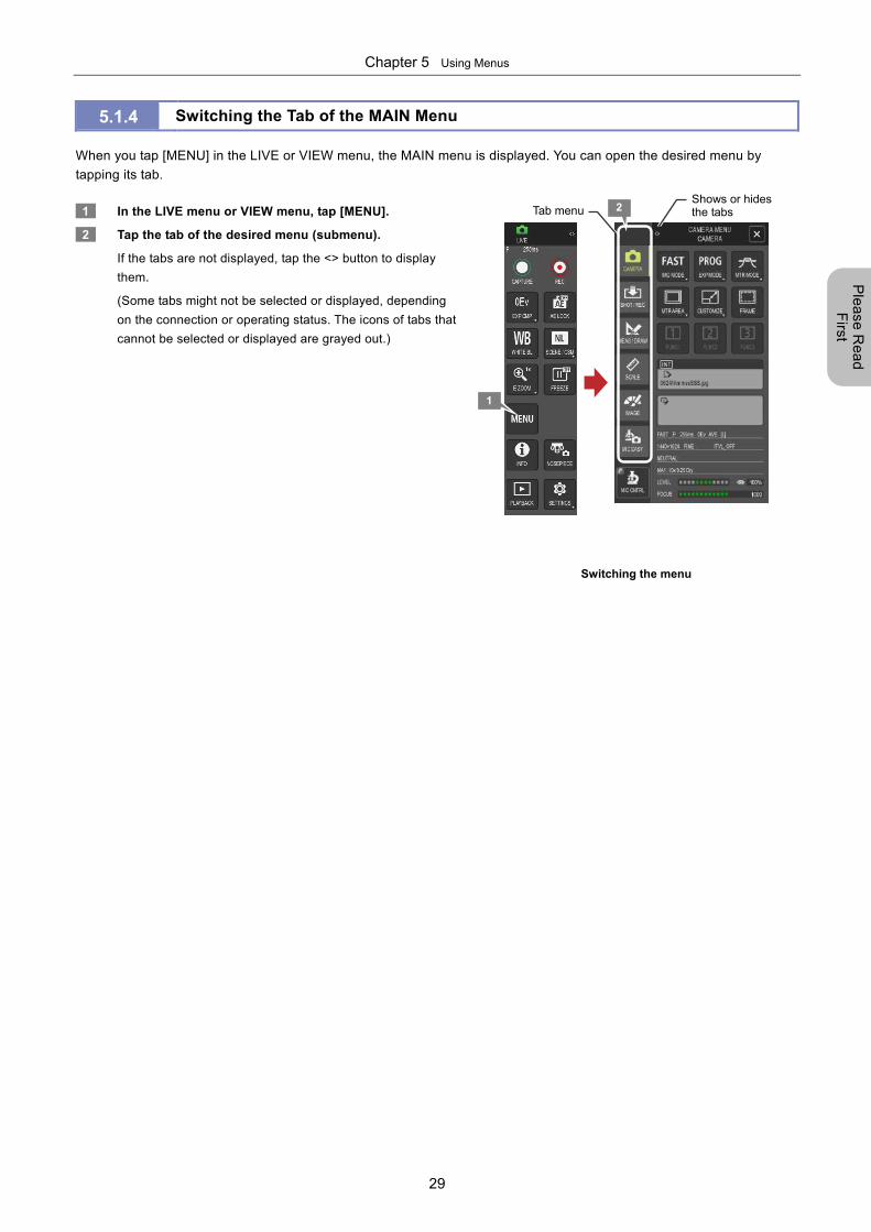
5.1.4 Switching the Tab of the MAIN Menu
When you tap [MENU] in the LIVE or VIEW menu, the MAIN menu is displayed. You can open the desired menu by
tapping its tab.
1 In the LIVE menu or VIEW menu, tap [MENU].
2 Tap the tab of the desired menu (submenu).
If the tabs are not displayed, tap the <> button to display
them.
(Some tabs might not be selected or displayed, depending
on the connection or operating status. The icons of tabs that
cannot be selected or displayed are grayed out.)
Switching the menu
1
2 Shows or hides the tabs Tab menu
Chapter 5 Using Menus
30
Ple
ase
Re
ad
F
irst
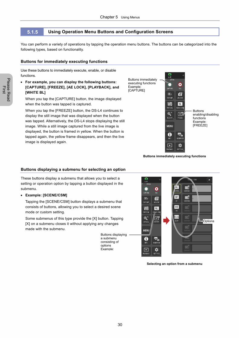
5.1.5 Using Operation Menu Buttons and Configuration Screens
You can perform a variety of operations by tapping the operation menu buttons. The buttons can be categorized into the
following types, based on functionality.
Buttons for immediately executing functions
Use these buttons to immediately execute, enable, or disable
functions.
For example, you can display the following buttons:
[CAPTURE], [FREEZE], [AE LOCK], [PLAYBACK], and
[WHITE BL]
When you tap the [CAPTURE] button, the image displayed
when the button was tapped is captured.
When you tap the [FREEZE] button, the DS-L4 continues to
display the still image that was displayed when the button
was tapped. Alternatively, the DS-L4 stops displaying the still
image. While a still image captured from the live image is
displayed, the button is framed in yellow. When the button is
tapped again, the yellow frame disappears, and then the live
image is displayed again.
Buttons immediately executing functions
Buttons displaying a submenu for selecting an option
These buttons display a submenu that allows you to select a
setting or operation option by tapping a button displayed in the
submenu.
Example: [SCENE/CSM]
Tapping the [SCENE/CSM] button displays a submenu that
consists of buttons, allowing you to select a desired scene
mode or custom setting.
Some submenus of this type provide the [X] button. Tapping
[X] on a submenu closes it without applying any changes
made with the submenu.
Selecting an option from a submenu
Buttons enabling/disabling functions Example: [FREEZE]
Buttons immediately executing functions Example: [CAPTURE]
Buttons displaying a submenu consisting of options Example:
Options
Chapter 5 Using Menus
31
Ple
ase
Re
ad
F
irst
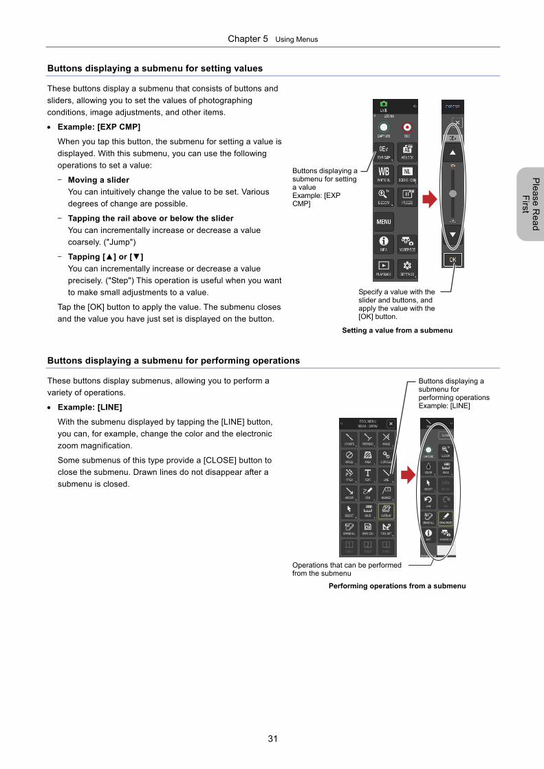
Buttons displaying a submenu for setting values
These buttons display a submenu that consists of buttons and
sliders, allowing you to set the values of photographing
conditions, image adjustments, and other items.
Example: [EXP CMP]
When you tap this button, the submenu for setting a value is
displayed. With this submenu, you can use the following
operations to set a value:
- Moving a slider
You can intuitively change the value to be set. Various
degrees of change are possible.
- Tapping the rail above or below the slider
You can incrementally increase or decrease a value
coarsely. ("Jump")
- Tapping [▲] or [▼]
You can incrementally increase or decrease a value
precisely. ("Step") This operation is useful when you want
to make small adjustments to a value.
Tap the [OK] button to apply the value. The submenu closes
and the value you have just set is displayed on the button.
Setting a value from a submenu
Buttons displaying a submenu for performing operations
These buttons display submenus, allowing you to perform a
variety of operations.
Example: [LINE]
With the submenu displayed by tapping the [LINE] button,
you can, for example, change the color and the electronic
zoom magnification.
Some submenus of this type provide a [CLOSE] button to
close the submenu. Drawn lines do not disappear after a
submenu is closed.
Performing operations from a submenu
Buttons displaying a submenu for setting a value Example: [EXP CMP]
Specify a value with the slider and buttons, and apply the value with the [OK] button.
Operations that can be performed from the submenu
Buttons displaying a submenu for performing operationsExample: [LINE]
Chapter 5 Using Menus
32
Ple
ase
Re
ad
F
irst
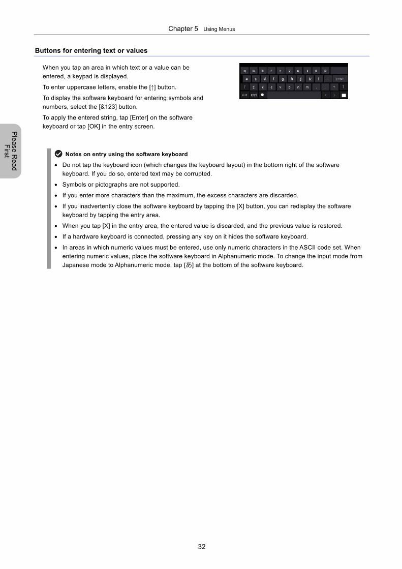
Buttons for entering text or values
When you tap an area in which text or a value can be
entered, a keypad is displayed.
To enter uppercase letters, enable the [↑] button.
To display the software keyboard for entering symbols and
numbers, select the [&123] button.
To apply the entered string, tap [Enter] on the software
keyboard or tap [OK] in the entry screen.
Notes on entry using the software keyboard
Do not tap the keyboard icon (which changes the keyboard layout) in the bottom right of the software
keyboard. If you do so, entered text may be corrupted.
Symbols or pictographs are not supported.
If you enter more characters than the maximum, the excess characters are discarded.
If you inadvertently close the software keyboard by tapping the [X] button, you can redisplay the software
keyboard by tapping the entry area.
When you tap [X] in the entry area, the entered value is discarded, and the previous value is restored.
If a hardware keyboard is connected, pressing any key on it hides the software keyboard.
In areas in which numeric values must be entered, use only numeric characters in the ASCII code set. When
entering numeric values, place the software keyboard in Alphanumeric mode. To change the input mode from
Japanese mode to Alphanumeric mode, tap [あ] at the bottom of the software keyboard.
Chapter 6 Capturing Images with Simple Operations
33
Photographing
Basics of D
S-L4
Part 2
Photographing Basics of the DS-L4
This part explains basic operations of the DS-L4 for photographing (capturing) images.
This part consists of the following chapters:
Chapter 6 Capturing Images with Simple Operations
Chapter 7 Tips on Photographing
Chapter 6 Capturing Images with Simple Operations
34
Photographing
Basics of D
S-L4
6 Capturing Images with Simple Operations
This chapter explains the operations for capturing images by using the LIVE menu and the [CAMERA MENU: CAMERA]
screen.
What is "capturing"?
"Capturing" is an operation to save the currently displayed image on to a storage media device as a still image.
With the DS-L4, you can capture the live image viewed through a microscope camera or the recorded image
displayed in playback mode. You can also add annotations or measurements to the live image or playback image
that you capture.
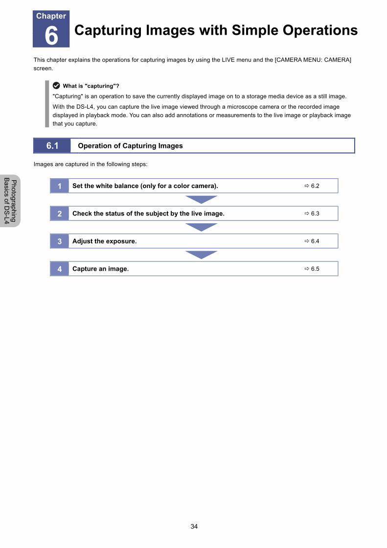
6.1 Operation of Capturing Images
Images are captured in the following steps:
1 Set the white balance (only for a color camera). 6.2
2 Check the status of the subject by the live image. 6.3
3 Adjust the exposure. 6.4
4 Capture an image. 6.5
Capturing Images with Simple OperationsChapter
6
Chapter 6 Capturing Images with Simple Operations
35
Photographing
Basics of D
S-L4
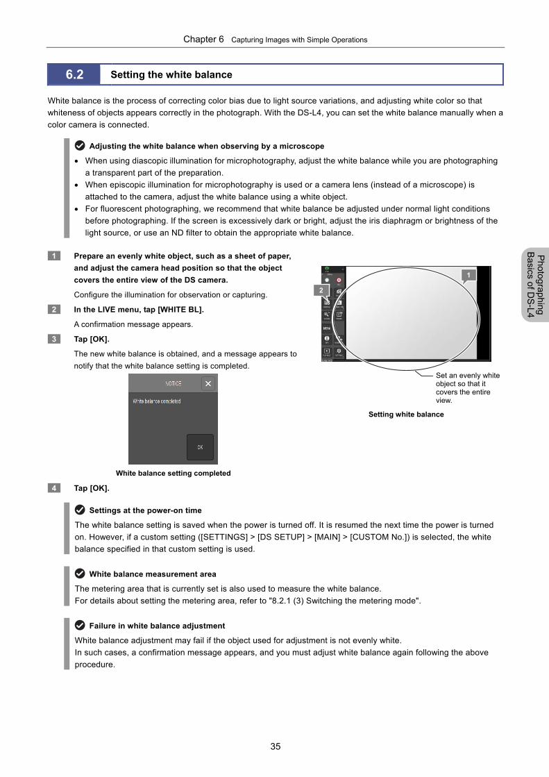
6.2 Setting the white balance
White balance is the process of correcting color bias due to light source variations, and adjusting white color so that
whiteness of objects appears correctly in the photograph. With the DS-L4, you can set the white balance manually when a
color camera is connected.
Adjusting the white balance when observing by a microscope
When using diascopic illumination for microphotography, adjust the white balance while you are photographing
a transparent part of the preparation.
When episcopic illumination for microphotography is used or a camera lens (instead of a microscope) is
attached to the camera, adjust the white balance using a white object.
For fluorescent photographing, we recommend that white balance be adjusted under normal light conditions
before photographing. If the screen is excessively dark or bright, adjust the iris diaphragm or brightness of the
light source, or use an ND filter to obtain the appropriate white balance.
1 Prepare an evenly white object, such as a sheet of paper,
and adjust the camera head position so that the object
covers the entire view of the DS camera.
Configure the illumination for observation or capturing.
2 In the LIVE menu, tap [WHITE BL].
A confirmation message appears.
3 Tap [OK].
The new white balance is obtained, and a message appears to
notify that the white balance setting is completed.
White balance setting completed
4 Tap [OK].
Setting white balance
Settings at the power-on time
The white balance setting is saved when the power is turned off. It is resumed the next time the power is turned
on. However, if a custom setting ([SETTINGS] > [DS SETUP] > [MAIN] > [CUSTOM No.]) is selected, the white
balance specified in that custom setting is used.
White balance measurement area
The metering area that is currently set is also used to measure the white balance.
For details about setting the metering area, refer to "8.2.1 (3) Switching the metering mode".
Failure in white balance adjustment
White balance adjustment may fail if the object used for adjustment is not evenly white.
In such cases, a confirmation message appears, and you must adjust white balance again following the above
procedure.
2
Set an evenly white object so that it covers the entire view.
1
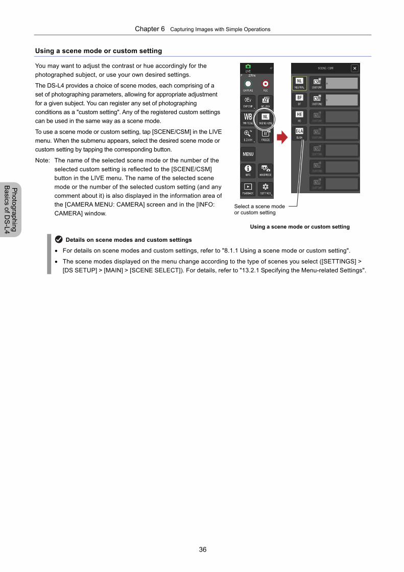
Chapter 6 Capturing Images with Simple Operations
36
Photographing
Basics of D
S-L4
Using a scene mode or custom setting
You may want to adjust the contrast or hue accordingly for the
photographed subject, or use your own desired settings.
The DS-L4 provides a choice of scene modes, each comprising of a
set of photographing parameters, allowing for appropriate adjustment
for a given subject. You can register any set of photographing
conditions as a "custom setting". Any of the registered custom settings
can be used in the same way as a scene mode.
To use a scene mode or custom setting, tap [SCENE/CSM] in the LIVE
menu. When the submenu appears, select the desired scene mode or
custom setting by tapping the corresponding button.
Note: The name of the selected scene mode or the number of the
selected custom setting is reflected to the [SCENE/CSM]
button in the LIVE menu. The name of the selected scene
mode or the number of the selected custom setting (and any
comment about it) is also displayed in the information area of
the [CAMERA MENU: CAMERA] screen and in the [INFO:
CAMERA] window.
Using a scene mode or custom setting
Details on scene modes and custom settings
For details on scene modes and custom settings, refer to "8.1.1 Using a scene mode or custom setting".
The scene modes displayed on the menu change according to the type of scenes you select ([SETTINGS] >
[DS SETUP] > [MAIN] > [SCENE SELECT]). For details, refer to "13.2.1 Specifying the Menu-related Settings".
Select a scene mode or custom setting
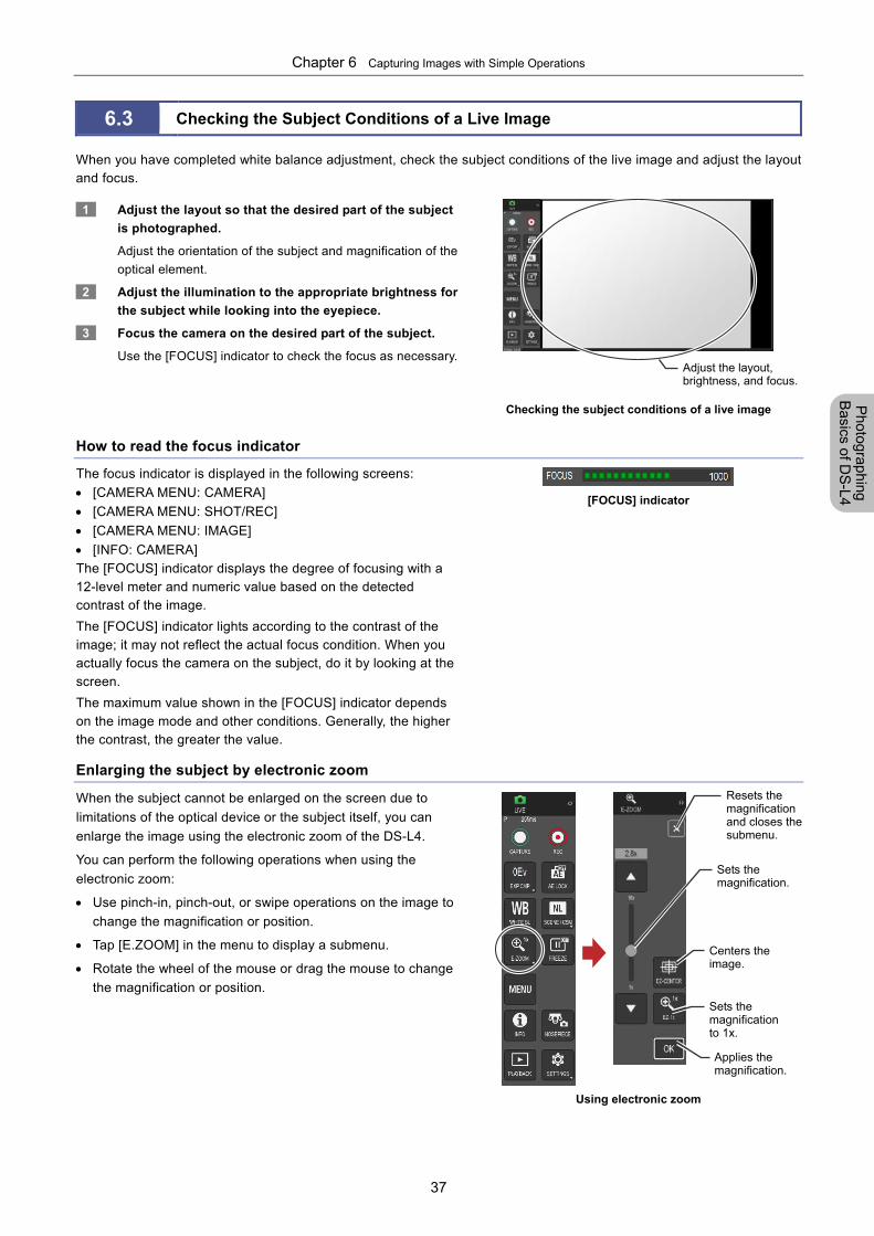
Chapter 6 Capturing Images with Simple Operations
37
Photographing
Basics of D
S-L4
6.3 Checking the Subject Conditions of a Live Image
When you have completed white balance adjustment, check the subject conditions of the live image and adjust the layout and focus.
1 Adjust the layout so that the desired part of the subject
is photographed.
Adjust the orientation of the subject and magnification of the
optical element.
2 Adjust the illumination to the appropriate brightness for
the subject while looking into the eyepiece.
3 Focus the camera on the desired part of the subject.
Use the [FOCUS] indicator to check the focus as necessary.
Checking the subject conditions of a live image
How to read the focus indicator
The focus indicator is displayed in the following screens:
[CAMERA MENU: CAMERA]
[CAMERA MENU: SHOT/REC]
[CAMERA MENU: IMAGE]
[INFO: CAMERA]
The [FOCUS] indicator displays the degree of focusing with a 12-level meter and numeric value based on the detected contrast of the image.
The [FOCUS] indicator lights according to the contrast of the image; it may not reflect the actual focus condition. When you actually focus the camera on the subject, do it by looking at the screen.
The maximum value shown in the [FOCUS] indicator depends on the image mode and other conditions. Generally, the higher the contrast, the greater the value.
[FOCUS] indicator
Enlarging the subject by electronic zoom
When the subject cannot be enlarged on the screen due to
limitations of the optical device or the subject itself, you can
enlarge the image using the electronic zoom of the DS-L4.
You can perform the following operations when using the
electronic zoom:
Use pinch-in, pinch-out, or swipe operations on the image to
change the magnification or position.
Tap [E.ZOOM] in the menu to display a submenu.
Rotate the wheel of the mouse or drag the mouse to change
the magnification or position.
Using electronic zoom
Sets the magnification to 1x.
Applies the magnification.
Resets the magnification and closes the submenu.
Centers the image.
Sets the magnification.
Adjust the layout, brightness, and focus.
Chapter 6 Capturing Images with Simple Operations
38
Photographing
Basics of D
S-L4
Using electronic zoom
Electronic zoom is a function to enlarge a section of an image. Note that, image quality decreases with larger magnification.
Electronic zoom can only magnify images. It cannot reduce the display size.
You can also capture an image enlarged by electronic zoom ([SCREEN CAP MODE] in [CAMERA MENU: SHOT/REC]).
Enlargement by electronic zoom is automatically canceled when you switch between LIVE mode and VIEW
mode, or switch the playback image.
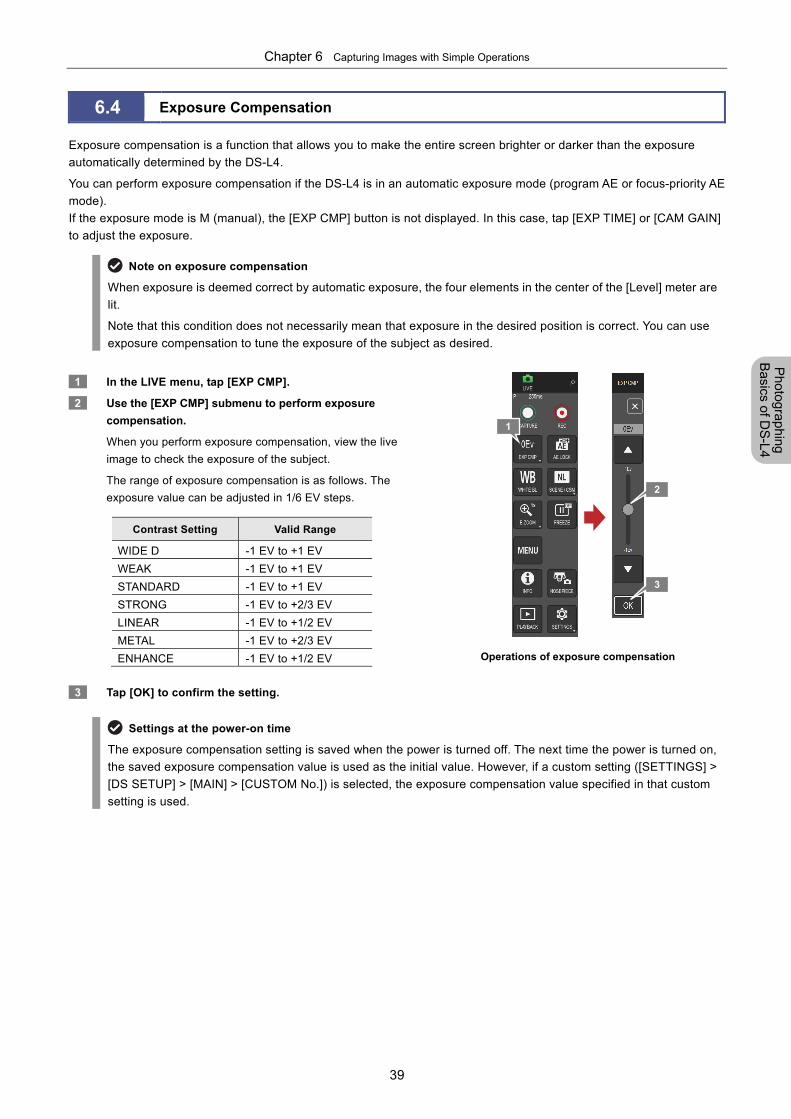
Chapter 6 Capturing Images with Simple Operations
39
Photographing
Basics of D
S-L4
6.4 Exposure Compensation
Exposure compensation is a function that allows you to make the entire screen brighter or darker than the exposure
automatically determined by the DS-L4.
You can perform exposure compensation if the DS-L4 is in an automatic exposure mode (program AE or focus-priority AE
mode).
If the exposure mode is M (manual), the [EXP CMP] button is not displayed. In this case, tap [EXP TIME] or [CAM GAIN]
to adjust the exposure.
Note on exposure compensation
When exposure is deemed correct by automatic exposure, the four elements in the center of the [Level] meter are
lit.
Note that this condition does not necessarily mean that exposure in the desired position is correct. You can use
exposure compensation to tune the exposure of the subject as desired.
1 In the LIVE menu, tap [EXP CMP].
2 Use the [EXP CMP] submenu to perform exposure
compensation.
When you perform exposure compensation, view the live
image to check the exposure of the subject.
The range of exposure compensation is as follows. The
exposure value can be adjusted in 1/6 EV steps.
Contrast Setting Valid Range
WIDE D -1 EV to +1 EV
WEAK -1 EV to +1 EV
STANDARD -1 EV to +1 EV
STRONG -1 EV to +2/3 EV
LINEAR -1 EV to +1/2 EV
METAL -1 EV to +2/3 EV
ENHANCE -1 EV to +1/2 EV
3 Tap [OK] to confirm the setting.
Operations of exposure compensation
Settings at the power-on time
The exposure compensation setting is saved when the power is turned off. The next time the power is turned on,
the saved exposure compensation value is used as the initial value. However, if a custom setting ([SETTINGS] >
[DS SETUP] > [MAIN] > [CUSTOM No.]) is selected, the exposure compensation value specified in that custom
setting is used.
1
2
3
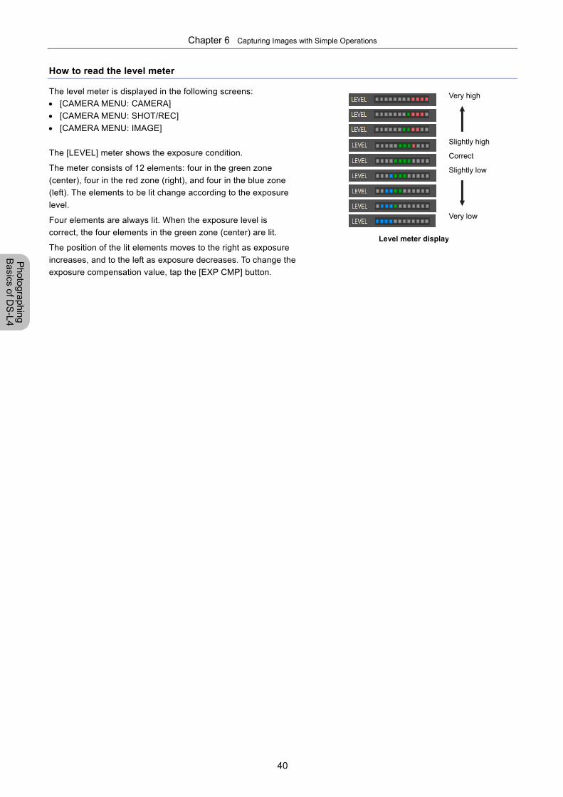
Chapter 6 Capturing Images with Simple Operations
40
Photographing
Basics of D
S-L4
How to read the level meter
The level meter is displayed in the following screens:
[CAMERA MENU: CAMERA]
[CAMERA MENU: SHOT/REC]
[CAMERA MENU: IMAGE]
The [LEVEL] meter shows the exposure condition.
The meter consists of 12 elements: four in the green zone
(center), four in the red zone (right), and four in the blue zone
(left). The elements to be lit change according to the exposure
level.
Four elements are always lit. When the exposure level is
correct, the four elements in the green zone (center) are lit.
The position of the lit elements moves to the right as exposure
increases, and to the left as exposure decreases. To change the
exposure compensation value, tap the [EXP CMP] button.
Level meter display
Very high
Slightly high
Correct
Slightly low
Very low
Chapter 6 Capturing Images with Simple Operations
41
Photographing
Basics of D
S-L4
6.5 Re-capturing Displayed Images
You can save the image displayed in the screen as a still image file.
Cautions on saving an image
Do not remove the storage media device while an image is being saved. If you do so, the image might not be stored
correctly. Alternatively, the DS-L4 or the storage media device might be damaged. While saving is in progress, the icon
indicating the wait state appears. Do not remove the recording media device while this icon is displayed.
If you use a USB memory drive as the recording media, do not remove it while its access lamp is lit.
Settings for saving image files
Before you start photographing, make sure that the following settings are specified:
Storage destination
With the DS-L4, captured images can be saved to the internal memory, microSD card, USB memory drive, or
network drive.
Destination drive and folder
If you use a recording media device as the storage destination, set the destination drive (recording media) and
folder. For the setting procedure, refer to "8.2.3 (7) Specifying the destination media and save folder".
Setting the file type and image size
Set the details of images to be saved. Specify the necessary settings so that images will be saved in the
desired conditions. For details, refer to "Chapter 8 Capturing Images with Advanced Setting Menu".
File names to be assigned to images
A file name is automatically assigned each time image data is saved. You can select the file naming format. To
do so, in the [CAMERA MENU: SHOT/REC] screen, tap [FILENAME], and then select [DATE&TIME] or [CONT.
No.]. For details, refer to "8.2.3 (10) Selecting the image file naming format".
In the file name display area of the [CAMERA MENU: CAMERA] screen, you can check the file name to be
assigned to the image that will be captured next. You can also set any image file name in that area. For the
operation procedure, refer to "8.2.3 (9) Checking/temporarily specifying the file name to be assigned".
Consecutive capture with the interval timer
"Consecutive capture" is a DS-L4 function that automatically captures images at regular intervals. To perform
consecutive capture, refer to "8.2.3 (1) Setting the shot mode (still image)".
Capture sound
With the sound volume set to [1] or higher, the capture sound is heard twice: once at the time of capturing
operation and once at completion of image data saving. To change the volume setting for the sound, refer to
"13.2.5 (1) Setting the capture sound volume".
Saving annotations and measurement results
Annotations (such as free-hand drawings or text comments) or measurement results (such as lengths or angles)
can be embedded into an image to be saved.
For details on the scale, annotation, and measurement functions, refer to "Chapter 11 Adding scales and
annotations to images" and "Chapter 12 On-Screen Measurement".
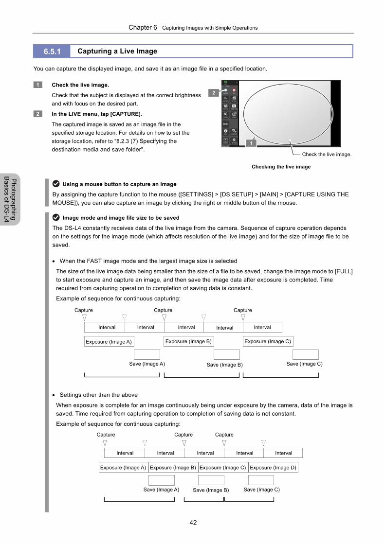
Chapter 6 Capturing Images with Simple Operations
42
Photographing
Basics of D
S-L4
6.5.1 Capturing a Live Image
You can capture the displayed image, and save it as an image file in a specified location.
1 Check the live image.
Check that the subject is displayed at the correct brightness
and with focus on the desired part.
2 In the LIVE menu, tap [CAPTURE].
The captured image is saved as an image file in the
specified storage location. For details on how to set the
storage location, refer to "8.2.3 (7) Specifying the
destination media and save folder".
Checking the live image
Using a mouse button to capture an image
By assigning the capture function to the mouse ([SETTINGS] > [DS SETUP] > [MAIN] > [CAPTURE USING THE
MOUSE]), you can also capture an image by clicking the right or middle button of the mouse.
Image mode and image file size to be saved
The DS-L4 constantly receives data of the live image from the camera. Sequence of capture operation depends
on the settings for the image mode (which affects resolution of the live image) and for the size of image file to be
saved.
When the FAST image mode and the largest image size is selected
The size of the live image data being smaller than the size of a file to be saved, change the image mode to [FULL]
to start exposure and capture an image, and then save the image data after exposure is completed. Time
required from capturing operation to completion of saving data is constant.
Example of sequence for continuous capturing:
Settings other than the above
When exposure is complete for an image continuously being under exposure by the camera, data of the image is
saved. Time required from capturing operation to completion of saving data is not constant.
Example of sequence for continuous capturing:
1
Check the live image.
2
Capture Capture Capture
Capture Capture Capture
Interval Interval Interval Interval Interval
Interval Interval Interval Interval Interval
Save (Image A) Save (Image C)Save (Image B)
Exposure (Image A) Exposure (Image B) Exposure (Image C)
Save (Image A) Save (Image C)Save (Image B)
Exposure (Image A) Exposure (Image B) Exposure (Image C) Exposure (Image D)
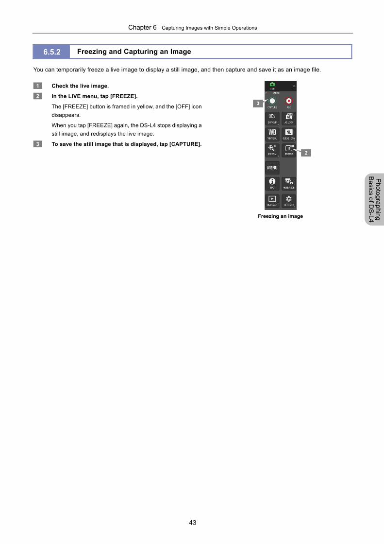
Chapter 6 Capturing Images with Simple Operations
43
Photographing
Basics of D
S-L4
6.5.2 Freezing and Capturing an Image
You can temporarily freeze a live image to display a still image, and then capture and save it as an image file.
1 Check the live image.
2 In the LIVE menu, tap [FREEZE].
The [FREEZE] button is framed in yellow, and the [OFF] icon
disappears.
When you tap [FREEZE] again, the DS-L4 stops displaying a
still image, and redisplays the live image.
3 To save the still image that is displayed, tap [CAPTURE].
Freezing an image
2
3
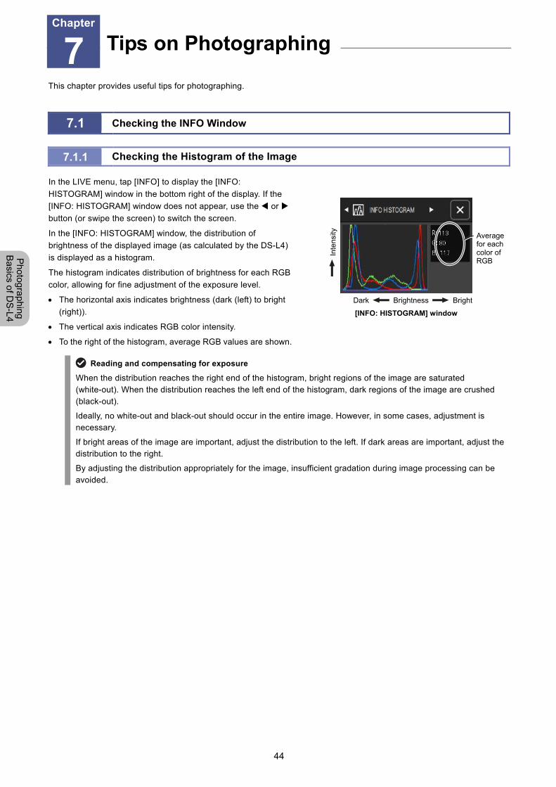
Chapter 7 Tips on Photographing
44
Photographing
Basics of D
S-L4
7 Tips on Photographing
This chapter provides useful tips for photographing.
7.1 Checking the INFO Window
7.1.1 Checking the Histogram of the Image
In the LIVE menu, tap [INFO] to display the [INFO:
HISTOGRAM] window in the bottom right of the display. If the
[INFO: HISTOGRAM] window does not appear, use the or
button (or swipe the screen) to switch the screen.
In the [INFO: HISTOGRAM] window, the distribution of
brightness of the displayed image (as calculated by the DS-L4)
is displayed as a histogram.
The histogram indicates distribution of brightness for each RGB
color, allowing for fine adjustment of the exposure level.
The horizontal axis indicates brightness (dark (left) to bright
(right)).
The vertical axis indicates RGB color intensity.
To the right of the histogram, average RGB values are shown.
Dark Brightness Bright
[INFO: HISTOGRAM] window
Reading and compensating for exposure
When the distribution reaches the right end of the histogram, bright regions of the image are saturated (white-out). When the distribution reaches the left end of the histogram, dark regions of the image are crushed (black-out).
Ideally, no white-out and black-out should occur in the entire image. However, in some cases, adjustment is necessary.
If bright areas of the image are important, adjust the distribution to the left. If dark areas are important, adjust the distribution to the right.
By adjusting the distribution appropriately for the image, insufficient gradation during image processing can be avoided.
Tips on Photographing Chapter
7
Inte
nsity
Average for each color of RGB
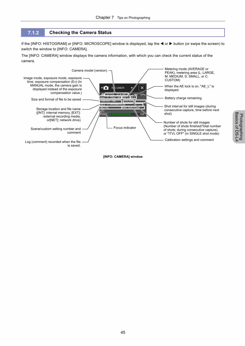
Chapter 7 Tips on Photographing
45
Photographing
Basics of D
S-L4
7.1.2 Checking the Camera Status
If the [INFO: HISTOGRAM] or [INFO: MICROSCOPE] window is displayed, tap the or button (or swipe the screen) to
switch the window to [INFO: CAMERA].
The [INFO: CAMERA] window displays the camera information, with which you can check the current status of the
camera.
[INFO: CAMERA] window
Log (comment) recorded when the fileis saved.
Focus indicator
Camera model (version)
Calibration settings and comment
Battery charge remaining
Metering mode (AVERAGE or PEAK), metering area (L: LARGE, M: MEDIUM, S: SMALL, or C: CUSTOM)
Number of shots for still images (Number of shots finished/Total number of shots; during consecutive capture), or "ITVL OFF" (in SINGLE shot mode)
Shot interval for still images (during consecutive capture, time before next shot)
When the AE lock is on, "AE_L" is displayed.
Storage location and file name([INT]: internal memory, [EXT]:
external recording media,or[NET]: network drive)
Size and format of file to be saved
Scene/custom setting number andcomment
Image mode, exposure mode, exposuretime, exposure compensation (Ev) (In
MANUAL mode, the camera gain isdisplayed instead of the exposure
compensation value.)
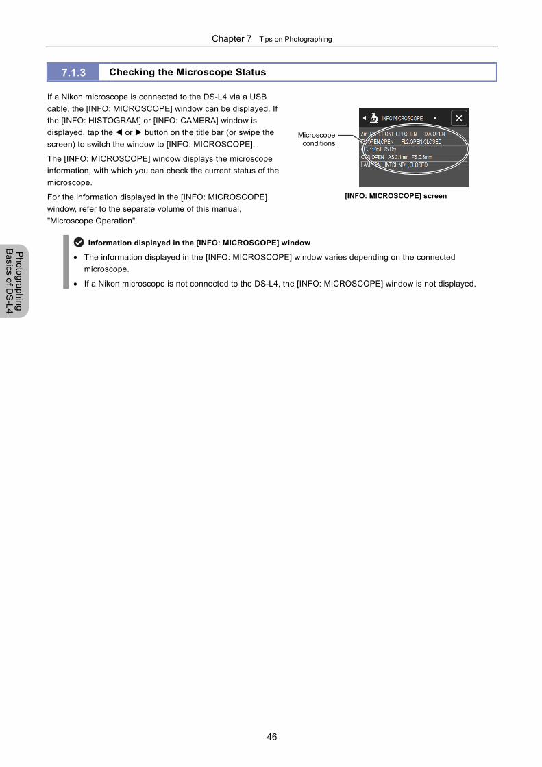
Chapter 7 Tips on Photographing
46
Photographing
Basics of D
S-L4
7.1.3 Checking the Microscope Status
If a Nikon microscope is connected to the DS-L4 via a USB
cable, the [INFO: MICROSCOPE] window can be displayed. If
the [INFO: HISTOGRAM] or [INFO: CAMERA] window is
displayed, tap the or button on the title bar (or swipe the
screen) to switch the window to [INFO: MICROSCOPE].
The [INFO: MICROSCOPE] window displays the microscope
information, with which you can check the current status of the
microscope.
For the information displayed in the [INFO: MICROSCOPE]
window, refer to the separate volume of this manual,
"Microscope Operation".
[INFO: MICROSCOPE] screen
Information displayed in the [INFO: MICROSCOPE] window
The information displayed in the [INFO: MICROSCOPE] window varies depending on the connected
microscope.
If a Nikon microscope is not connected to the DS-L4, the [INFO: MICROSCOPE] window is not displayed.
Microscopeconditions
Chapter 7 Tips on Photographing
47
Photographing
Basics of D
S-L4
7.2 Setting the Environment for Microscope Photographing
If you connect a camera to the microscope, set up the environment for microscope photographing as described below.
7.2.1 Setting up the Ambient Environment (1) Adjusting the ambient brightness
When you photograph a dark specimen by using a fluorescent microscope, room illumination might enter the optical path
of the microscope. For this reason, perform photographing in a dark room.
Place caps on the binocular eyepieces to prevent light from entering.
(2) Preventing tremor
During microscope photographing, because resolution is high, image quality is affected by even the slightest vibration.
Place the microscope on a sturdy, vibration-free surface, supported by a stable floor, to isolate the microscope from
vibration.
You can reduce the impact of vibration by using a vibration isolation table suitable for your microscope. Especially during
photographing, try to avoid touching the surface on which the microscope is placed.
7.2.2 Setting up the Microscope (1) Using an appropriate filter
For color images
Insert an NCB filter in the optical path.
For monochrome images
Insert a filter (suitable for the photographing purpose) in the optical path.
Generally, a GIF (Green Interference) filter provides good contrast. Using a filter of a complementary color to the
specimen enhances contrast.
Using a filter
The way to insert and remove filters is different depending on the microscope. Refer to the manual of your
microscope.
A third-party color compensation filter (CC filter) can be inserted into the optical path of the microscope to
compensate for differences in color balance caused by different exposure times.
When using a phase contrast microscope or an interference microscope (two luminous fluxes or multiple
luminous fluxes), you can enhance contrast by using a green interference filter (GIF) or a monochrome
interference filter (IF).
Some microscope models may require a heat-absorbing filter.
What is an NCB filter?
An NCB (neutral color balance) filter is a color-balancing compensation filter used to adjust color temperature to
daylight values in microscopes that use a halogen bulb as a light source.
What is a complementary color?
For example, green and magenta, red and cyan, and blue and yellow are all pairs of complementary colors. When
complementary colors overlap, their respective hues cancel each other out.
Chapter 7 Tips on Photographing
48
Photographing
Basics of D
S-L4
(2) Setting the field diaphragm
Adjust the field diaphragm so that it circumscribes the viewfield. The field diaphragm has a significant impact on contrast,
especially for fluorescent specimens against dark backgrounds.
Note: For details on how to adjust the field diaphragm, refer to the manual of your microscope.
(3) Setting the aperture diaphragm
Adjust the aperture diaphragm in the following way according to the lighting.
For diascopic illumination
Generally, the numeric value of the condenser aperture diaphragm should be adjusted to approximately 70% to 80% of the
numerical aperture (NA) of the objective.
For episcopic illumination
Generally, the aperture diaphragm should be adjusted to approximately 70% to 80% of the size of the pupil of the objective.
(Check pupil size by removing the eyepiece and looking into the eyepiece tube.)
Adjustment of the aperture diaphragm
For details on aperture diaphragm adjustment, refer to the manual of your microscope.
For photographed images that have greater depth of focus, reduce the aperture diaphragm. Note that reducing
the aperture may limit the performance of the objective.
What is depth of focus?
"Depth of focus" refers to the in-focus range along the direction vertical to the specimen surface. Although
reducing the aperture diaphragm extends the depth of focus, doing so will also reduce resolution. Adjust the
aperture diaphragm as needed.
(4) Adjusting the focus on the subject
Adjust the focus of the microscope so that the image can be clearly seen on the display panel.
Chapter 7 Tips on Photographing
49
Photographing
Basics of D
S-L4
(5) Adjusting the lighting
When photographing a color image, the color reproducibility of the image depends on the lamp voltage.
When a halogen lamp is used as the light source, increasing the lamp voltage produces a bluish light, and decreasing the
lamp voltage produces a reddish light.
Except in cases where it is specifically necessary to adjust the tone, the voltage should be set to the correct level for
microphotography, which depends on the microscope being used. Since this level varies for each type of microscope,
refer to your microscope's instruction manual.
Note: If the lamp voltage changes, adjust the white balance once again.
White balance when observing by a microscope
Consider the following when you adjust the white balance while viewing on the microscope.
When using diascopic illumination for microphotography, adjust the white balance while you are photographing
a transparent part of the preparation.
When episcopic illumination for microphotography is used or a camera lens (instead of a microscope) is
attached to the camera, adjust the white balance using a white object.
For fluorescent photographing, we recommend that white balance be adjusted under normal light conditions
before photographing. If the screen is excessively dark or bright, adjust the iris diaphragm or brightness of the
light source, or use an ND filter to obtain the appropriate white balance.
(6) Adjusting the exposure time
An exposure time in the range of 4 ms to 60 ms is appropriate for a normal photographing. To obtain an appropriate
exposure time, adjust the light intensity for the microscope by using an ND filter.
If the DS-L4 is set for automatic exposure, the camera gain and the exposure time are automatically changed to obtain an
appropriate exposure. Consequently, insufficient light increases camera gain, resulting in coarser images and longer
exposure time, which makes focusing difficult.
What is an ND filter?
An ND filter is a filter that affects only the amount of light passed, not the color balance of the light. For example,
an "ND2" filter cuts transmitted light in half, while an "ND16" filter reduces transmitted light to 1/16th of the actual
level.
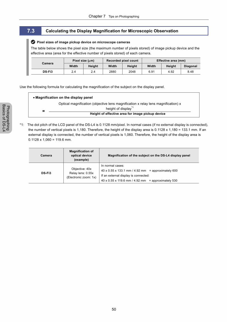
Chapter 7 Tips on Photographing
50
Photographing
Basics of D
S-L4
7.3 Calculating the Display Magnification for Microscopic Observation
Pixel sizes of image pickup device on microscope cameras
The table below shows the pixel size (the maximum number of pixels stored) of image pickup device and the
effective area (area for the effective number of pixels stored) of each camera.
Camera Pixel size (m) Recorded pixel count Effective area (mm)
Width Height Width Height Width Height Diagonal
DS-Fi3 2.4 2.4 2880 2048 6.91 4.92 8.48
Use the following formula for calculating the magnification of the subject on the display panel.
Magnification on the display panel
Optical magnification (objective lens magnification x relay lens magnification) x
height of display*1
Height of effective area for image pickup device
*1: The dot pitch of the LCD panel of the DS-L4 is 0.1128 mm/pixel. In normal cases (if no external display is connected),
the number of vertical pixels is 1,180. Therefore, the height of the display area is 0.1128 x 1,180 = 133.1 mm. If an
external display is connected, the number of vertical pixels is 1,060. Therefore, the height of the display area is
0.1128 x 1,060 = 119.6 mm.
Camera Magnification of optical device
(example) Magnification of the subject on the DS-L4 display panel
DS-Fi3 Objective: 40x
Relay lens: 0.55x (Electronic zoom: 1x)
In normal cases:
40 x 0.55 x 133.1 mm / 4.92 mm = approximately 600
If an external display is connected:
40 x 0.55 x 119.6 mm / 4.92 mm = approximately 530
=
Chapter 8 Capturing Images with the Advanced Setting Menu
51
Photographing and
Replaying Im
ages
Part 3
Photographing and Replaying Images
This part explains how to configure various settings to observe and capture images with desired conditions, how to replay
the captured images on the display panel, and how to delete them.
This part consists of the following chapters:
Chapter 8 Capturing Images with Advanced Setting Menu
Chapter 9 Playing Back and Deleting Images
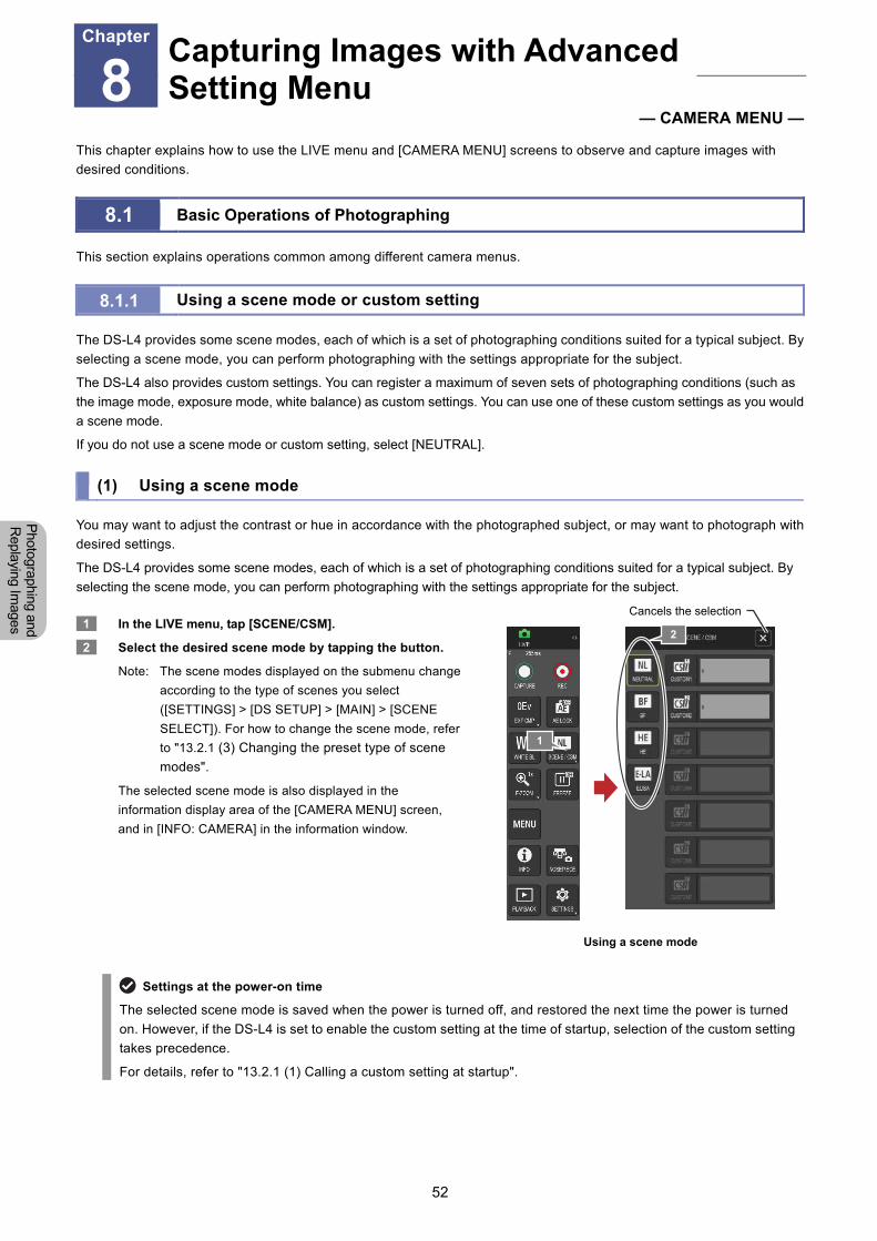
Chapter 8 Capturing Images with the Advanced Setting Menu
52
Photographing and
Replaying Im
ages
8 Capturing Images with Advanced Setting Menu
— CAMERA MENU —
This chapter explains how to use the LIVE menu and [CAMERA MENU] screens to observe and capture images with
desired conditions.
8.1 Basic Operations of Photographing
This section explains operations common among different camera menus.
8.1.1 Using a scene mode or custom setting
The DS-L4 provides some scene modes, each of which is a set of photographing conditions suited for a typical subject. By
selecting a scene mode, you can perform photographing with the settings appropriate for the subject.
The DS-L4 also provides custom settings. You can register a maximum of seven sets of photographing conditions (such as
the image mode, exposure mode, white balance) as custom settings. You can use one of these custom settings as you would
a scene mode.
If you do not use a scene mode or custom setting, select [NEUTRAL].
(1) Using a scene mode
You may want to adjust the contrast or hue in accordance with the photographed subject, or may want to photograph with
desired settings.
The DS-L4 provides some scene modes, each of which is a set of photographing conditions suited for a typical subject. By
selecting the scene mode, you can perform photographing with the settings appropriate for the subject.
1 In the LIVE menu, tap [SCENE/CSM].
2 Select the desired scene mode by tapping the button.
Note: The scene modes displayed on the submenu change
according to the type of scenes you select
([SETTINGS] > [DS SETUP] > [MAIN] > [SCENE
SELECT]). For how to change the scene mode, refer
to "13.2.1 (3) Changing the preset type of scene
modes".
The selected scene mode is also displayed in the
information display area of the [CAMERA MENU] screen,
and in [INFO: CAMERA] in the information window.
Using a scene mode
Settings at the power-on time
The selected scene mode is saved when the power is turned off, and restored the next time the power is turned
on. However, if the DS-L4 is set to enable the custom setting at the time of startup, selection of the custom setting
takes precedence.
For details, refer to "13.2.1 (1) Calling a custom setting at startup".
Capturing Images with Advanced Setting Menu
Chapter
8
1
2
Cancels the selection
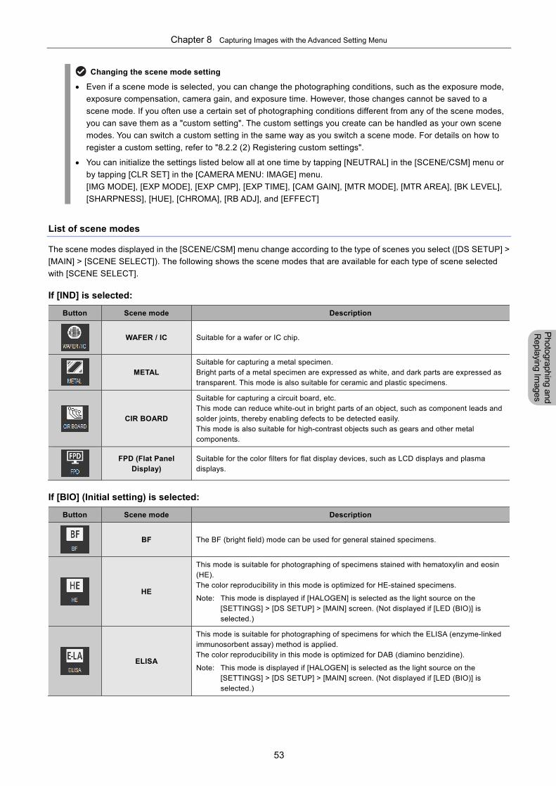
Chapter 8 Capturing Images with the Advanced Setting Menu
53
Photographing and
Replaying Im
ages
Changing the scene mode setting
Even if a scene mode is selected, you can change the photographing conditions, such as the exposure mode,
exposure compensation, camera gain, and exposure time. However, those changes cannot be saved to a
scene mode. If you often use a certain set of photographing conditions different from any of the scene modes,
you can save them as a "custom setting". The custom settings you create can be handled as your own scene
modes. You can switch a custom setting in the same way as you switch a scene mode. For details on how to
register a custom setting, refer to "8.2.2 (2) Registering custom settings".
You can initialize the settings listed below all at one time by tapping [NEUTRAL] in the [SCENE/CSM] menu or
by tapping [CLR SET] in the [CAMERA MENU: IMAGE] menu.
[IMG MODE], [EXP MODE], [EXP CMP], [EXP TIME], [CAM GAIN], [MTR MODE], [MTR AREA], [BK LEVEL],
[SHARPNESS], [HUE], [CHROMA], [RB ADJ], and [EFFECT]
List of scene modes
The scene modes displayed in the [SCENE/CSM] menu change according to the type of scenes you select ([DS SETUP] >
[MAIN] > [SCENE SELECT]). The following shows the scene modes that are available for each type of scene selected
with [SCENE SELECT].
If [IND] is selected:
Button Scene mode Description
WAFER / IC Suitable for a wafer or IC chip.
METAL
Suitable for capturing a metal specimen. Bright parts of a metal specimen are expressed as white, and dark parts are expressed as transparent. This mode is also suitable for ceramic and plastic specimens.
CIR BOARD
Suitable for capturing a circuit board, etc. This mode can reduce white-out in bright parts of an object, such as component leads and solder joints, thereby enabling defects to be detected easily. This mode is also suitable for high-contrast objects such as gears and other metal components.
FPD (Flat Panel Display)
Suitable for the color filters for flat display devices, such as LCD displays and plasma displays.
If [BIO] (Initial setting) is selected:
Button Scene mode Description
BF The BF (bright field) mode can be used for general stained specimens.
HE
This mode is suitable for photographing of specimens stained with hematoxylin and eosin (HE). The color reproducibility in this mode is optimized for HE-stained specimens.
Note: This mode is displayed if [HALOGEN] is selected as the light source on the [SETTINGS] > [DS SETUP] > [MAIN] screen. (Not displayed if [LED (BIO)] is selected.)
ELISA
This mode is suitable for photographing of specimens for which the ELISA (enzyme-linked immunosorbent assay) method is applied. The color reproducibility in this mode is optimized for DAB (diamino benzidine).
Note: This mode is displayed if [HALOGEN] is selected as the light source on the [SETTINGS] > [DS SETUP] > [MAIN] screen. (Not displayed if [LED (BIO)] is selected.)
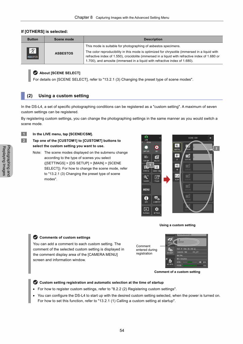
Chapter 8 Capturing Images with the Advanced Setting Menu
54
Photographing and
Replaying Im
ages
If [OTHERS] is selected:
Button Scene mode Description
ASBESTOS
This mode is suitable for photographing of asbestos specimens.
The color reproducibility in this mode is optimized for chrysotile (immersed in a liquid with refractive index of 1.550), crocidolite (immersed in a liquid with refractive index of 1.680 or 1.700), and amosite (immersed in a liquid with refractive index of 1.680).
About [SCENE SELECT]
For details on [SCENE SELECT], refer to "13.2.1 (3) Changing the preset type of scene modes".
(2) Using a custom setting
In the DS-L4, a set of specific photographing conditions can be registered as a "custom setting". A maximum of seven
custom settings can be registered.
By registering custom settings, you can change the photographing settings in the same manner as you would switch a
scene mode.
1 In the LIVE menu, tap [SCENE/CSM].
2 Tap one of the [CUSTOM1] to [CUSTOM7] buttons to
select the custom setting you want to use.
Note: The scene modes displayed on the submenu change
according to the type of scenes you select
([SETTINGS] > [DS SETUP] > [MAIN] > [SCENE
SELECT]). For how to change the scene mode, refer
to "13.2.1 (3) Changing the preset type of scene
modes".
Using a custom setting
Comments of custom settings
You can add a comment to each custom setting. The
comment of the selected custom setting is displayed in
the comment display area of the [CAMERA MENU]
screen and information window.
Comment of a custom setting
Custom setting registration and automatic selection at the time of startup
For how to register custom settings, refer to "8.2.2 (2) Registering custom settings".
You can configure the DS-L4 to start up with the desired custom setting selected, when the power is turned on.
For how to set this function, refer to "13.2.1 (1) Calling a custom setting at startup".
Comment entered during registration
1
2
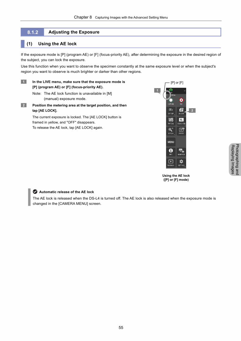
Chapter 8 Capturing Images with the Advanced Setting Menu
55
Photographing and
Replaying Im
ages
8.1.2 Adjusting the Exposure (1) Using the AE lock
If the exposure mode is [P] (program AE) or [F] (focus-priority AE), after determining the exposure in the desired region of
the subject, you can lock the exposure.
Use this function when you want to observe the specimen constantly at the same exposure level or when the subject's
region you want to observe is much brighter or darker than other regions.
1 In the LIVE menu, make sure that the exposure mode is
[P] (program AE) or [F] (focus-priority AE).
Note: The AE lock function is unavailable in [M]
(manual) exposure mode.
2 Position the metering area at the target position, and then
tap [AE LOCK].
The current exposure is locked. The [AE LOCK] button is
framed in yellow, and "OFF" disappears.
To release the AE lock, tap [AE LOCK] again.
Using the AE lock ([P] or [F] mode)
Automatic release of the AE lock
The AE lock is released when the DS-L4 is turned off. The AE lock is also released when the exposure mode is
changed in the [CAMERA MENU] screen.
2
[P] or [F]
1
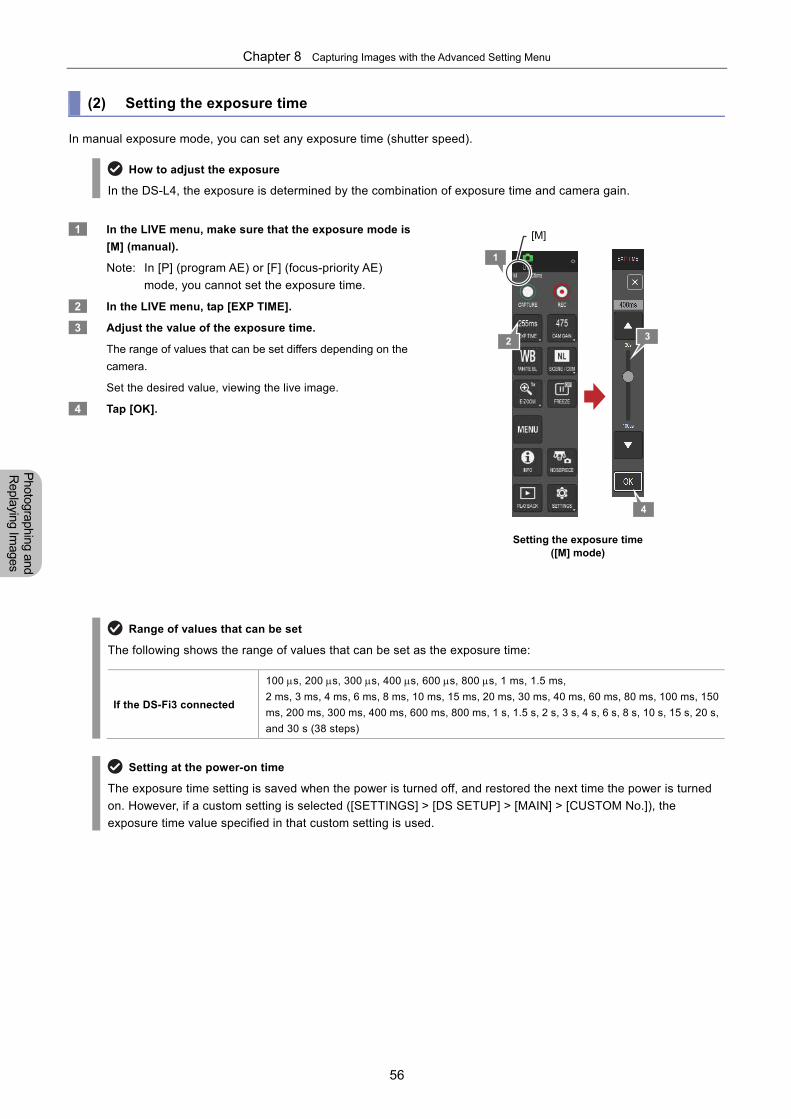
Chapter 8 Capturing Images with the Advanced Setting Menu
56
Photographing and
Replaying Im
ages
(2) Setting the exposure time
In manual exposure mode, you can set any exposure time (shutter speed).
How to adjust the exposure
In the DS-L4, the exposure is determined by the combination of exposure time and camera gain.
1 In the LIVE menu, make sure that the exposure mode is
[M] (manual).
Note: In [P] (program AE) or [F] (focus-priority AE)
mode, you cannot set the exposure time.
2 In the LIVE menu, tap [EXP TIME].
3 Adjust the value of the exposure time.
The range of values that can be set differs depending on the
camera.
Set the desired value, viewing the live image.
4 Tap [OK].
Setting the exposure time ([M] mode)
Range of values that can be set
The following shows the range of values that can be set as the exposure time:
If the DS-Fi3 connected
100 s, 200 s, 300 s, 400 s, 600 s, 800 s, 1 ms, 1.5 ms,
2 ms, 3 ms, 4 ms, 6 ms, 8 ms, 10 ms, 15 ms, 20 ms, 30 ms, 40 ms, 60 ms, 80 ms, 100 ms, 150
ms, 200 ms, 300 ms, 400 ms, 600 ms, 800 ms, 1 s, 1.5 s, 2 s, 3 s, 4 s, 6 s, 8 s, 10 s, 15 s, 20 s,
and 30 s (38 steps)
Setting at the power-on time
The exposure time setting is saved when the power is turned off, and restored the next time the power is turned
on. However, if a custom setting is selected ([SETTINGS] > [DS SETUP] > [MAIN] > [CUSTOM No.]), the
exposure time value specified in that custom setting is used.
4
2
[M]
3
1
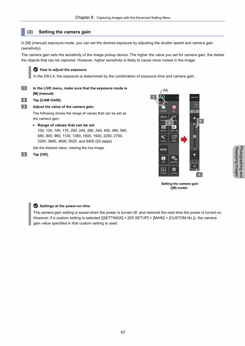
Chapter 8 Capturing Images with the Advanced Setting Menu
57
Photographing and
Replaying Im
ages
(3) Setting the camera gain
In [M] (manual) exposure mode, you can set the desired exposure by adjusting the shutter speed and camera gain
(sensitivity).
The camera gain sets the sensitivity of the image pickup device. The higher the value you set for camera gain, the darker
the objects that can be captured. However, higher sensitivity is likely to cause more noises in the image.
How to adjust the exposure
In the DS-L4, the exposure is determined by the combination of exposure time and camera gain.
1 In the LIVE menu, make sure that the exposure mode is
[M] (manual).
2 Tap [CAM GAIN].
3 Adjust the value of the camera gain.
The following shows the range of values that can be set as
the camera gain:
Range of values that can be set
100, 120, 140, 170, 200, 240, 280, 340, 400, 480, 560,
680, 800, 960, 1130, 1360, 1600, 1920, 2250, 2700,
3200, 3840, 4600, 5520, and 6400 (25 steps)
Set the desired value, viewing the live image.
4 Tap [OK].
Setting the camera gain ([M] mode)
Settings at the power-on time
The camera gain setting is saved when the power is turned off, and restored the next time the power is turned on.
However, if a custom setting is selected ([SETTINGS] > [DS SETUP] > [MAIN] > [CUSTOM No.]), the camera
gain value specified in that custom setting is used.
4
2
[M]
3
1
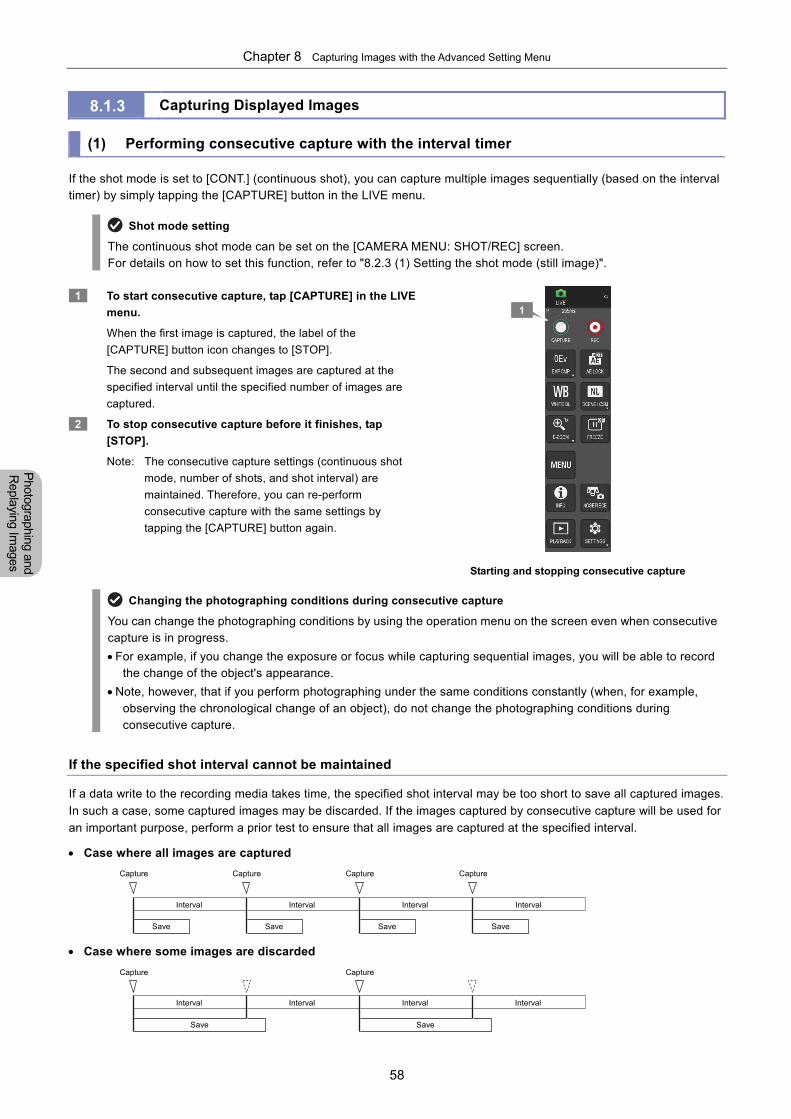
Chapter 8 Capturing Images with the Advanced Setting Menu
58
Photographing and
Replaying Im
ages
8.1.3 Capturing Displayed Images (1) Performing consecutive capture with the interval timer If the shot mode is set to [CONT.] (continuous shot), you can capture multiple images sequentially (based on the interval timer) by simply tapping the [CAPTURE] button in the LIVE menu.
Shot mode setting
The continuous shot mode can be set on the [CAMERA MENU: SHOT/REC] screen. For details on how to set this function, refer to "8.2.3 (1) Setting the shot mode (still image)".
1 To start consecutive capture, tap [CAPTURE] in the LIVE
menu.
When the first image is captured, the label of the
[CAPTURE] button icon changes to [STOP].
The second and subsequent images are captured at the
specified interval until the specified number of images are
captured.
2 To stop consecutive capture before it finishes, tap
[STOP].
Note: The consecutive capture settings (continuous shot
mode, number of shots, and shot interval) are
maintained. Therefore, you can re-perform
consecutive capture with the same settings by
tapping the [CAPTURE] button again.
Starting and stopping consecutive capture
Changing the photographing conditions during consecutive capture
You can change the photographing conditions by using the operation menu on the screen even when consecutive capture is in progress.
For example, if you change the exposure or focus while capturing sequential images, you will be able to record the change of the object's appearance.
Note, however, that if you perform photographing under the same conditions constantly (when, for example, observing the chronological change of an object), do not change the photographing conditions during consecutive capture.
If the specified shot interval cannot be maintained
If a data write to the recording media takes time, the specified shot interval may be too short to save all captured images.
In such a case, some captured images may be discarded. If the images captured by consecutive capture will be used for
an important purpose, perform a prior test to ensure that all images are captured at the specified interval.
Case where all images are captured
Case where some images are discarded
1
Capture Capture Capture
Capture Capture
Interval Interval Interval
Interval Interval Interval Interval
Save Save Save
Save Save
Capture
Interval
Save
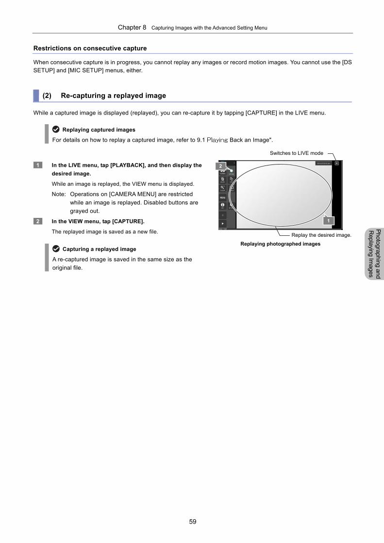
Chapter 8 Capturing Images with the Advanced Setting Menu
59
Photographing and
Replaying Im
ages
Restrictions on consecutive capture
When consecutive capture is in progress, you cannot replay any images or record motion images. You cannot use the [DS SETUP] and [MIC SETUP] menus, either.
(2) Re-capturing a replayed image
While a captured image is displayed (replayed), you can re-capture it by tapping [CAPTURE] in the LIVE menu.
Replaying captured images
For details on how to replay a captured image, refer to 9.1 Playing Back an Image".
1 In the LIVE menu, tap [PLAYBACK], and then display the
desired image.
While an image is replayed, the VIEW menu is displayed.
Note: Operations on [CAMERA MENU] are restricted
while an image is replayed. Disabled buttons are
grayed out.
2 In the VIEW menu, tap [CAPTURE].
The replayed image is saved as a new file.
Capturing a replayed image
A re-captured image is saved in the same size as the
original file.
Replaying photographed images
Replay the desired image.
1
2
Switches to LIVE mode
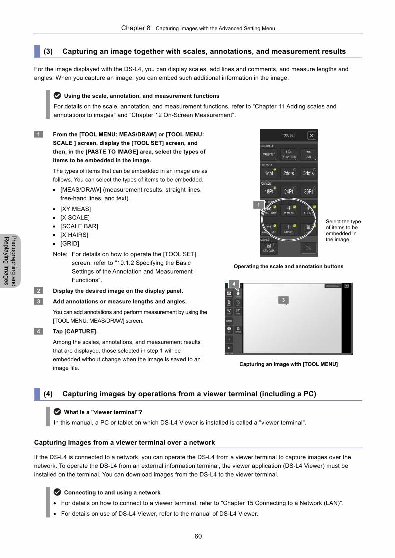
Chapter 8 Capturing Images with the Advanced Setting Menu
60
Photographing and
Replaying Im
ages
(3) Capturing an image together with scales, annotations, and measurement results
For the image displayed with the DS-L4, you can display scales, add lines and comments, and measure lengths and
angles. When you capture an image, you can embed such additional information in the image.
Using the scale, annotation, and measurement functions
For details on the scale, annotation, and measurement functions, refer to "Chapter 11 Adding scales and
annotations to images" and "Chapter 12 On-Screen Measurement".
1 From the [TOOL MENU: MEAS/DRAW] or [TOOL MENU:
SCALE ] screen, display the [TOOL SET] screen, and
then, in the [PASTE TO IMAGE] area, select the types of
items to be embedded in the image.
The types of items that can be embedded in an image are as
follows. You can select the types of items to be embedded.
[MEAS/DRAW] (measurement results, straight lines,
free-hand lines, and text)
[XY MEAS]
[X SCALE]
[SCALE BAR]
[X HAIRS]
[GRID]
Note: For details on how to operate the [TOOL SET]
screen, refer to "10.1.2 Specifying the Basic
Settings of the Annotation and Measurement
Functions".
2 Display the desired image on the display panel.
3 Add annotations or measure lengths and angles.
You can add annotations and perform measurement by using the
[TOOL MENU: MEAS/DRAW] screen.
4 Tap [CAPTURE].
Among the scales, annotations, and measurement results
that are displayed, those selected in step 1 will be
embedded without change when the image is saved to an
image file.
Operating the scale and annotation buttons
Capturing an image with [TOOL MENU]
(4) Capturing images by operations from a viewer terminal (including a PC)
What is a "viewer terminal"?
In this manual, a PC or tablet on which DS-L4 Viewer is installed is called a "viewer terminal".
Capturing images from a viewer terminal over a network
If the DS-L4 is connected to a network, you can operate the DS-L4 from a viewer terminal to capture images over the
network. To operate the DS-L4 from an external information terminal, the viewer application (DS-L4 Viewer) must be
installed on the terminal. You can download images from the DS-L4 to the viewer terminal.
Connecting to and using a network
For details on how to connect to a viewer terminal, refer to "Chapter 15 Connecting to a Network (LAN)".
For details on use of DS-L4 Viewer, refer to the manual of DS-L4 Viewer.
1
Select the type of items to be embedded in the image.
4
3
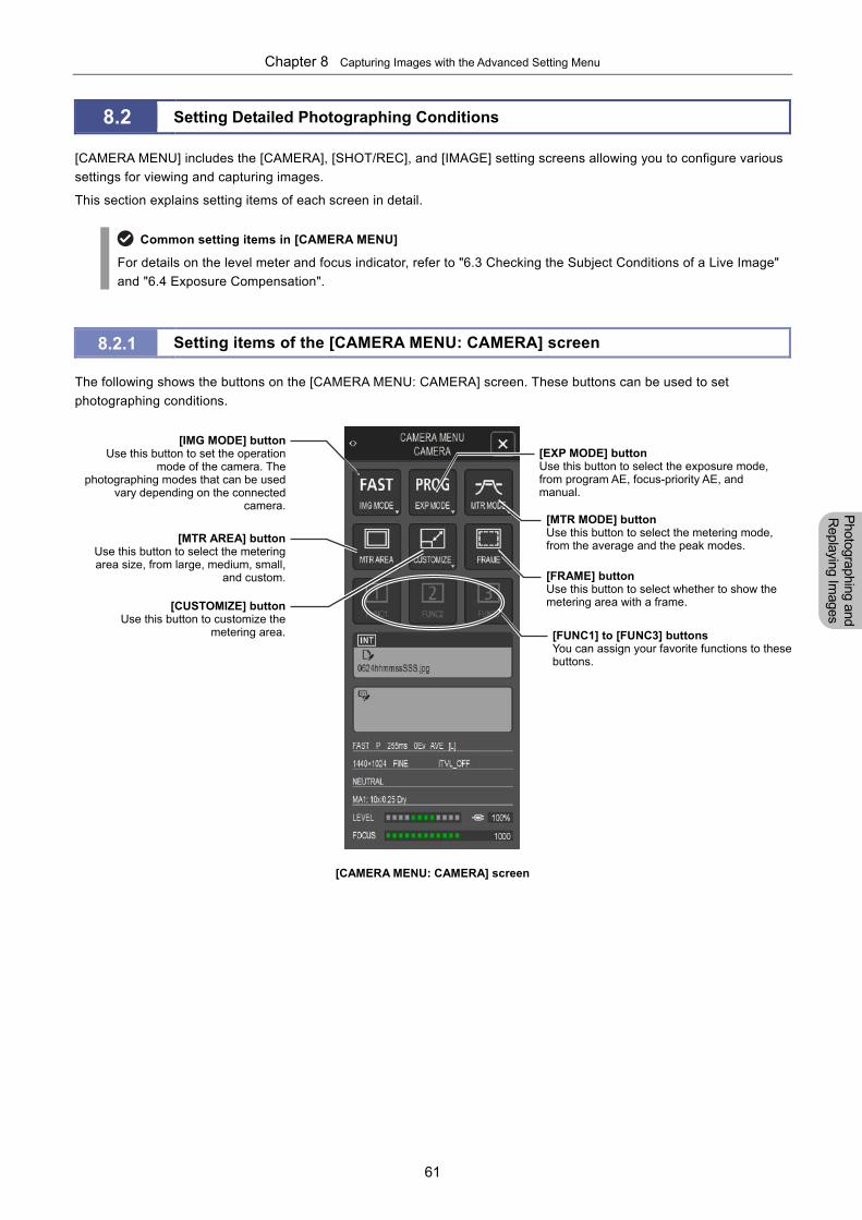
Chapter 8 Capturing Images with the Advanced Setting Menu
61
Photographing and
Replaying Im
ages
8.2 Setting Detailed Photographing Conditions
[CAMERA MENU] includes the [CAMERA], [SHOT/REC], and [IMAGE] setting screens allowing you to configure various
settings for viewing and capturing images.
This section explains setting items of each screen in detail.
Common setting items in [CAMERA MENU]
For details on the level meter and focus indicator, refer to "6.3 Checking the Subject Conditions of a Live Image"
and "6.4 Exposure Compensation".
8.2.1 Setting items of the [CAMERA MENU: CAMERA] screen
The following shows the buttons on the [CAMERA MENU: CAMERA] screen. These buttons can be used to set
photographing conditions.
[CAMERA MENU: CAMERA] screen
[IMG MODE] buttonUse this button to set the operation
mode of the camera. Thephotographing modes that can be used
vary depending on the connectedcamera.
[MTR MODE] buttonUse this button to select the metering mode, from the average and the peak modes.
[FUNC1] to [FUNC3] buttonsYou can assign your favorite functions to these buttons.
[EXP MODE] buttonUse this button to select the exposure mode, from program AE, focus-priority AE, and manual.
[MTR AREA] buttonUse this button to select the meteringarea size, from large, medium, small,
and custom. [FRAME] buttonUse this button to select whether to show the metering area with a frame. [CUSTOMIZE] button
Use this button to customize themetering area.
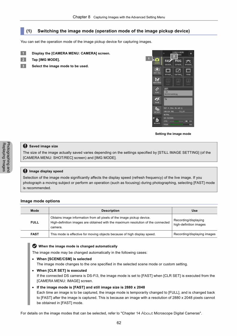
Chapter 8 Capturing Images with the Advanced Setting Menu
62
Photographing and
Replaying Im
ages
(1) Switching the image mode (operation mode of the image pickup device)
You can set the operation mode of the image pickup device for capturing images.
1 Display the [CAMERA MENU: CAMERA] screen.
2 Tap [IMG MODE].
3 Select the image mode to be used.
Setting the image mode
Saved image size
The size of the image actually saved varies depending on the settings specified by [STILL IMAGE SETTING] (of the
[CAMERA MENU: SHOT/REC] screen) and [IMG MODE].
Image display speed
Selection of the image mode significantly affects the display speed (refresh frequency) of the live image. If you
photograph a moving subject or perform an operation (such as focusing) during photographing, selecting [FAST] mode
is recommended.
Image mode options
Mode Description Use
FULL
Obtains image information from all pixels of the image pickup device.
High-definition images are obtained with the maximum resolution of the connected
camera.
Recording/displaying high-definition images
FAST This mode is effective for moving objects because of high display speed. Recording/displaying images
When the image mode is changed automatically
The image mode may be changed automatically in the following cases:
When [SCENE/CSM] is selected
The image mode changes to the one specified in the selected scene mode or custom setting.
When [CLR SET] is executed
If the connected DS camera is DS-Fi3, the image mode is set to [FAST] when [CLR SET] is executed from the
[CAMERA MENU: IMAGE] screen.
If the image mode is [FAST] and still image size is 2880 x 2048
Each time an image is to be captured, the image mode is temporarily changed to [FULL], and is changed back
to [FAST] after the image is captured. This is because an image with a resolution of 2880 x 2048 pixels cannot
be obtained in [FAST] mode.
For details on the image modes that can be selected, refer to "Chapter 14 About Microscope Digital Cameras".
1 2
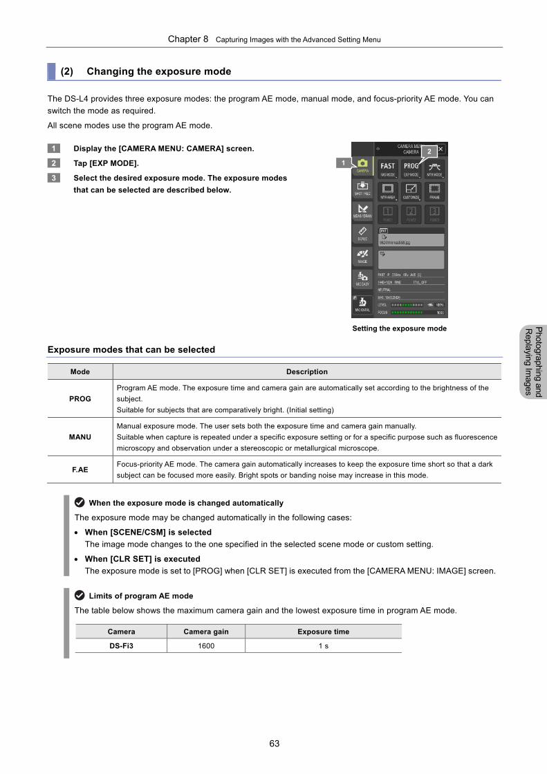
Chapter 8 Capturing Images with the Advanced Setting Menu
63
Photographing and
Replaying Im
ages
(2) Changing the exposure mode
The DS-L4 provides three exposure modes: the program AE mode, manual mode, and focus-priority AE mode. You can
switch the mode as required.
All scene modes use the program AE mode.
1 Display the [CAMERA MENU: CAMERA] screen.
2 Tap [EXP MODE].
3 Select the desired exposure mode. The exposure modes
that can be selected are described below.
Setting the exposure mode
Exposure modes that can be selected
Mode Description
PROG
Program AE mode. The exposure time and camera gain are automatically set according to the brightness of the
subject.
Suitable for subjects that are comparatively bright. (Initial setting)
MANU
Manual exposure mode. The user sets both the exposure time and camera gain manually.
Suitable when capture is repeated under a specific exposure setting or for a specific purpose such as fluorescence
microscopy and observation under a stereoscopic or metallurgical microscope.
F.AE Focus-priority AE mode. The camera gain automatically increases to keep the exposure time short so that a dark
subject can be focused more easily. Bright spots or banding noise may increase in this mode.
When the exposure mode is changed automatically
The exposure mode may be changed automatically in the following cases:
When [SCENE/CSM] is selected
The image mode changes to the one specified in the selected scene mode or custom setting.
When [CLR SET] is executed
The exposure mode is set to [PROG] when [CLR SET] is executed from the [CAMERA MENU: IMAGE] screen.
Limits of program AE mode
The table below shows the maximum camera gain and the lowest exposure time in program AE mode.
Camera Camera gain Exposure time
DS-Fi3 1600 1 s
1
2
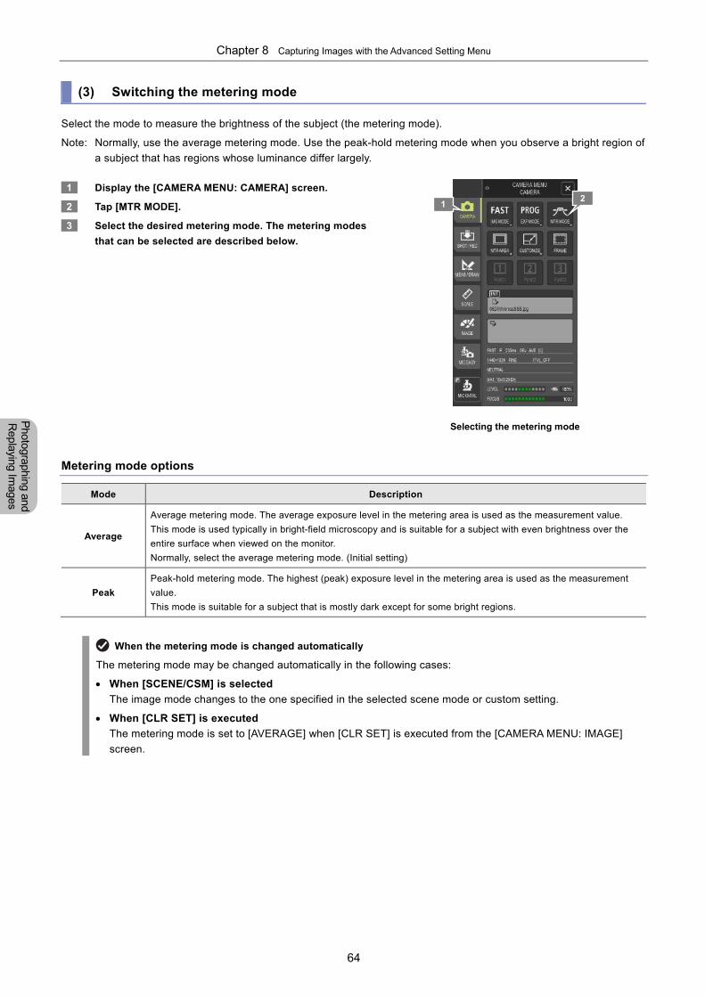
Chapter 8 Capturing Images with the Advanced Setting Menu
64
Photographing and
Replaying Im
ages
(3) Switching the metering mode
Select the mode to measure the brightness of the subject (the metering mode).
Note: Normally, use the average metering mode. Use the peak-hold metering mode when you observe a bright region of
a subject that has regions whose luminance differ largely.
1 Display the [CAMERA MENU: CAMERA] screen.
2 Tap [MTR MODE].
3 Select the desired metering mode. The metering modes
that can be selected are described below.
Selecting the metering mode
Metering mode options
Mode Description
Average
Average metering mode. The average exposure level in the metering area is used as the measurement value.
This mode is used typically in bright-field microscopy and is suitable for a subject with even brightness over the
entire surface when viewed on the monitor.
Normally, select the average metering mode. (Initial setting)
Peak
Peak-hold metering mode. The highest (peak) exposure level in the metering area is used as the measurement
value.
This mode is suitable for a subject that is mostly dark except for some bright regions.
When the metering mode is changed automatically
The metering mode may be changed automatically in the following cases:
When [SCENE/CSM] is selected
The image mode changes to the one specified in the selected scene mode or custom setting.
When [CLR SET] is executed
The metering mode is set to [AVERAGE] when [CLR SET] is executed from the [CAMERA MENU: IMAGE]
screen.
1 2
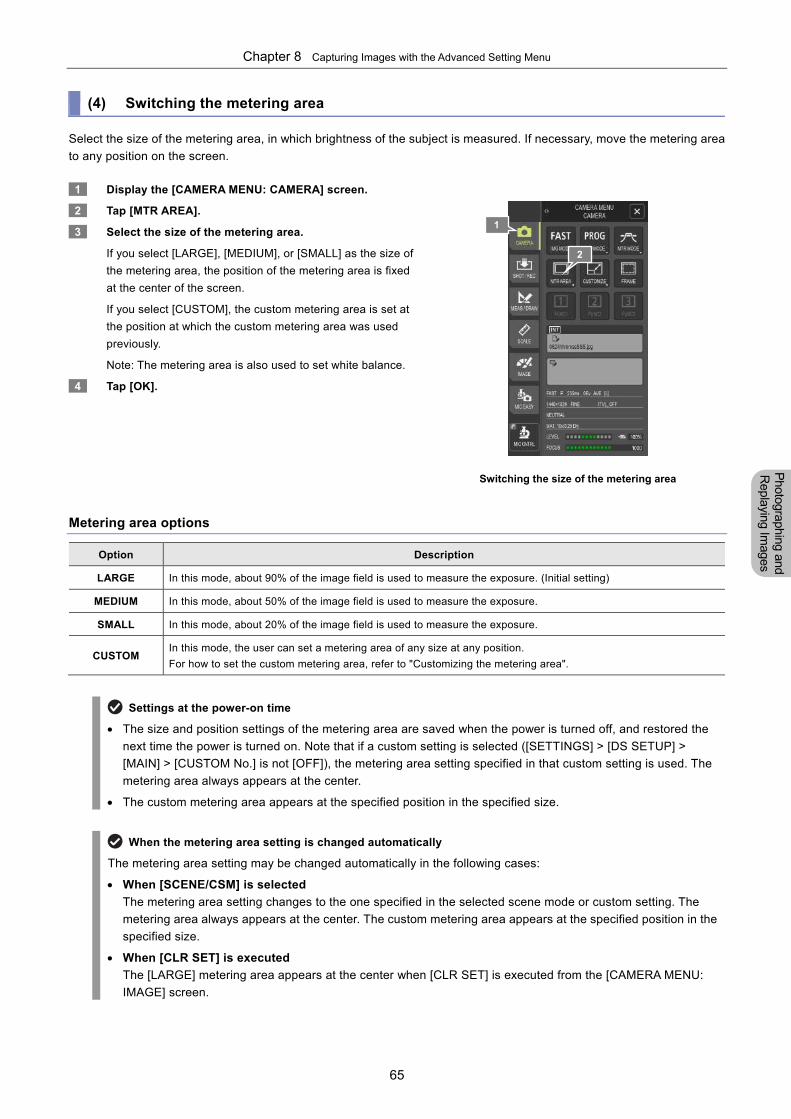
Chapter 8 Capturing Images with the Advanced Setting Menu
65
Photographing and
Replaying Im
ages
(4) Switching the metering area
Select the size of the metering area, in which brightness of the subject is measured. If necessary, move the metering area
to any position on the screen.
1 Display the [CAMERA MENU: CAMERA] screen.
2 Tap [MTR AREA].
3 Select the size of the metering area.
If you select [LARGE], [MEDIUM], or [SMALL] as the size of
the metering area, the position of the metering area is fixed
at the center of the screen.
If you select [CUSTOM], the custom metering area is set at
the position at which the custom metering area was used
previously.
Note: The metering area is also used to set white balance.
4 Tap [OK].
Switching the size of the metering area
Metering area options
Option Description
LARGE In this mode, about 90% of the image field is used to measure the exposure. (Initial setting)
MEDIUM In this mode, about 50% of the image field is used to measure the exposure.
SMALL In this mode, about 20% of the image field is used to measure the exposure.
CUSTOM In this mode, the user can set a metering area of any size at any position.
For how to set the custom metering area, refer to "Customizing the metering area".
Settings at the power-on time
The size and position settings of the metering area are saved when the power is turned off, and restored the
next time the power is turned on. Note that if a custom setting is selected ([SETTINGS] > [DS SETUP] >
[MAIN] > [CUSTOM No.] is not [OFF]), the metering area setting specified in that custom setting is used. The
metering area always appears at the center.
The custom metering area appears at the specified position in the specified size.
When the metering area setting is changed automatically
The metering area setting may be changed automatically in the following cases:
When [SCENE/CSM] is selected
The metering area setting changes to the one specified in the selected scene mode or custom setting. The
metering area always appears at the center. The custom metering area appears at the specified position in the
specified size.
When [CLR SET] is executed
The [LARGE] metering area appears at the center when [CLR SET] is executed from the [CAMERA MENU:
IMAGE] screen.
1
2
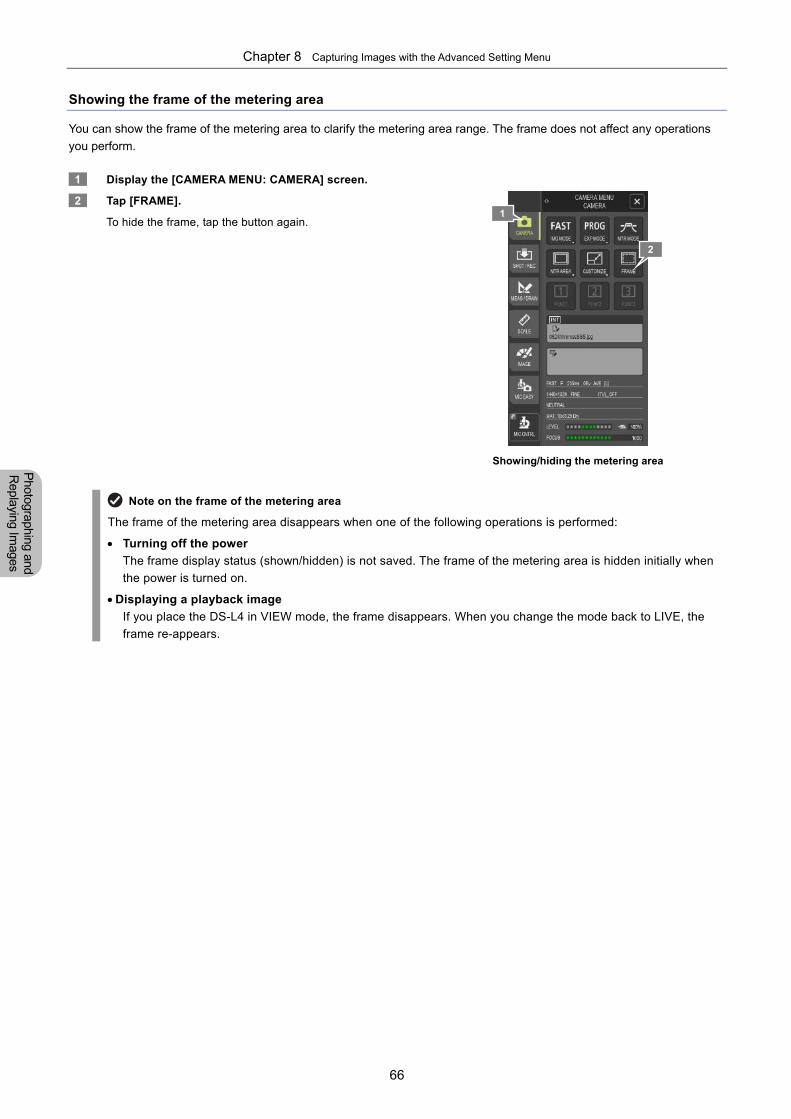
Chapter 8 Capturing Images with the Advanced Setting Menu
66
Photographing and
Replaying Im
ages
Showing the frame of the metering area
You can show the frame of the metering area to clarify the metering area range. The frame does not affect any operations
you perform.
1 Display the [CAMERA MENU: CAMERA] screen.
2 Tap [FRAME].
To hide the frame, tap the button again.
Showing/hiding the metering area
Note on the frame of the metering area
The frame of the metering area disappears when one of the following operations is performed:
Turning off the power
The frame display status (shown/hidden) is not saved. The frame of the metering area is hidden initially when
the power is turned on.
Displaying a playback image
If you place the DS-L4 in VIEW mode, the frame disappears. When you change the mode back to LIVE, the
frame re-appears.
1
2
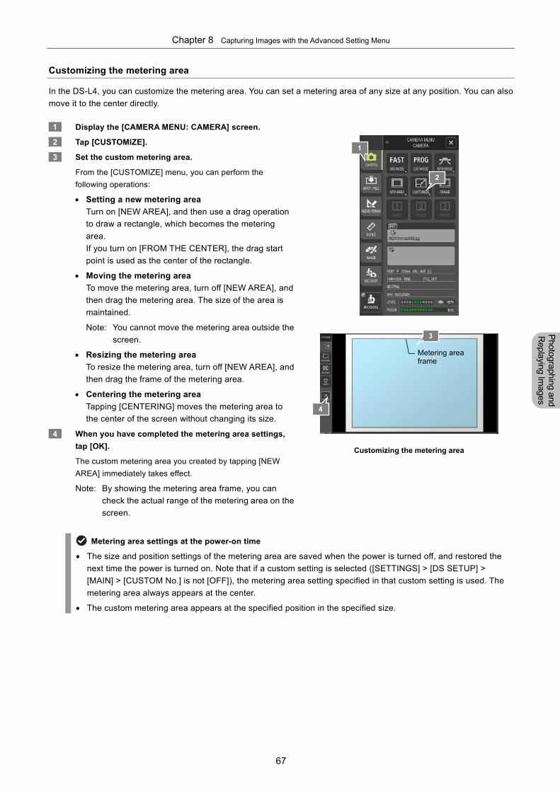
Chapter 8 Capturing Images with the Advanced Setting Menu
67
Photographing and
Replaying Im
ages
Customizing the metering area
In the DS-L4, you can customize the metering area. You can set a metering area of any size at any position. You can also
move it to the center directly.
1 Display the [CAMERA MENU: CAMERA] screen.
2 Tap [CUSTOMIZE].
3 Set the custom metering area.
From the [CUSTOMIZE] menu, you can perform the
following operations:
Setting a new metering area
Turn on [NEW AREA], and then use a drag operation
to draw a rectangle, which becomes the metering
area.
If you turn on [FROM THE CENTER], the drag start
point is used as the center of the rectangle.
Moving the metering area
To move the metering area, turn off [NEW AREA], and
then drag the metering area. The size of the area is
maintained.
Note: You cannot move the metering area outside the
screen.
Resizing the metering area
To resize the metering area, turn off [NEW AREA], and
then drag the frame of the metering area.
Centering the metering area
Tapping [CENTERING] moves the metering area to
the center of the screen without changing its size.
4 When you have completed the metering area settings,
tap [OK].
The custom metering area you created by tapping [NEW
AREA] immediately takes effect.
Note: By showing the metering area frame, you can
check the actual range of the metering area on the
screen.
Customizing the metering area
Metering area settings at the power-on time
The size and position settings of the metering area are saved when the power is turned off, and restored the
next time the power is turned on. Note that if a custom setting is selected ([SETTINGS] > [DS SETUP] >
[MAIN] > [CUSTOM No.] is not [OFF]), the metering area setting specified in that custom setting is used. The
metering area always appears at the center.
The custom metering area appears at the specified position in the specified size.
Metering area frame
4
3
1
2
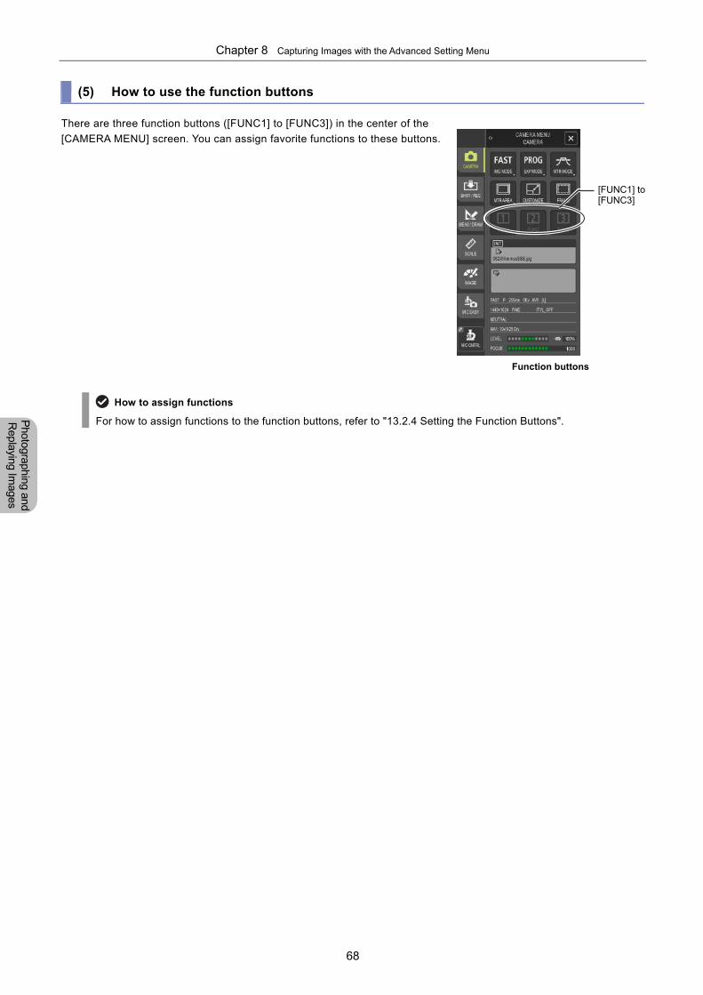
Chapter 8 Capturing Images with the Advanced Setting Menu
68
Photographing and
Replaying Im
ages
(5) How to use the function buttons
There are three function buttons ([FUNC1] to [FUNC3]) in the center of the
[CAMERA MENU] screen. You can assign favorite functions to these buttons.
Function buttons
How to assign functions
For how to assign functions to the function buttons, refer to "13.2.4 Setting the Function Buttons".
[FUNC1] to [FUNC3]
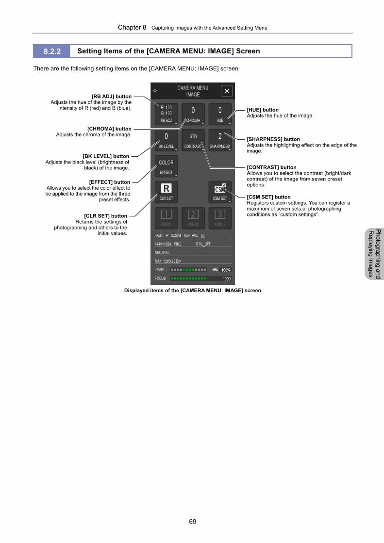
Chapter 8 Capturing Images with the Advanced Setting Menu
69
Photographing and
Replaying Im
ages
8.2.2 Setting Items of the [CAMERA MENU: IMAGE] Screen
There are the following setting items on the [CAMERA MENU: IMAGE] screen:
Displayed items of the [CAMERA MENU: IMAGE] screen
[CHROMA] buttonAdjusts the chroma of the image.
[BK LEVEL] buttonAdjusts the black level (brightness of
black) of the image.
[EFFECT] buttonAllows you to select the color effect tobe applied to the image from the three
preset effects.
[SHARPNESS] buttonAdjusts the highlighting effect on the edge of the image.
[HUE] buttonAdjusts the hue of the image.
[CONTRAST] buttonAllows you to select the contrast (bright/dark contrast) of the image from seven preset options.
[CLR SET] buttonReturns the settings of
photographing and others to theinitial values.
[CSM SET] buttonRegisters custom settings. You can register a maximum of seven sets of photographing conditions as "custom settings".
[RB ADJ] buttonAdjusts the hue of the image by the
intensity of R (red) and B (blue).
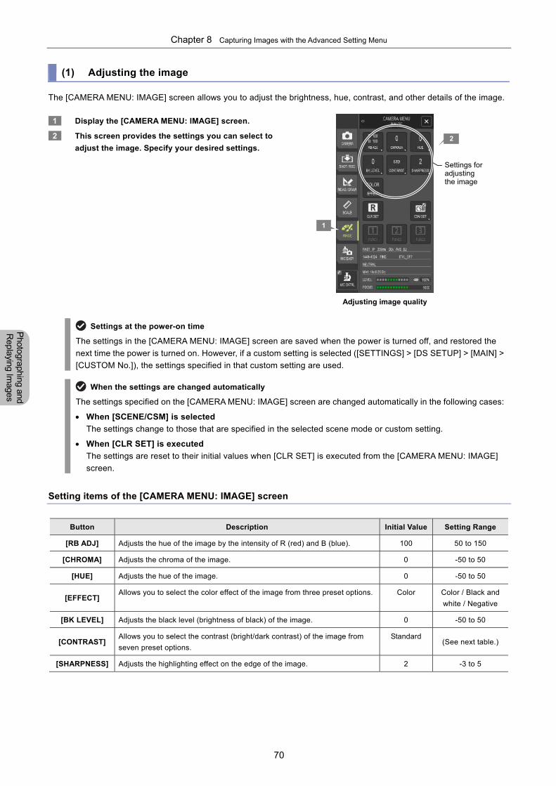
Chapter 8 Capturing Images with the Advanced Setting Menu
70
Photographing and
Replaying Im
ages
(1) Adjusting the image
The [CAMERA MENU: IMAGE] screen allows you to adjust the brightness, hue, contrast, and other details of the image.
1 Display the [CAMERA MENU: IMAGE] screen.
2 This screen provides the settings you can select to
adjust the image. Specify your desired settings.
Adjusting image quality
Settings at the power-on time
The settings in the [CAMERA MENU: IMAGE] screen are saved when the power is turned off, and restored the
next time the power is turned on. However, if a custom setting is selected ([SETTINGS] > [DS SETUP] > [MAIN] >
[CUSTOM No.]), the settings specified in that custom setting are used.
When the settings are changed automatically
The settings specified on the [CAMERA MENU: IMAGE] screen are changed automatically in the following cases:
When [SCENE/CSM] is selected
The settings change to those that are specified in the selected scene mode or custom setting.
When [CLR SET] is executed
The settings are reset to their initial values when [CLR SET] is executed from the [CAMERA MENU: IMAGE]
screen.
Setting items of the [CAMERA MENU: IMAGE] screen
Button Description Initial Value Setting Range
[RB ADJ] Adjusts the hue of the image by the intensity of R (red) and B (blue). 100 50 to 150
[CHROMA] Adjusts the chroma of the image. 0 -50 to 50
[HUE] Adjusts the hue of the image. 0 -50 to 50
[EFFECT] Allows you to select the color effect of the image from three preset options. Color Color / Black and
white / Negative
[BK LEVEL] Adjusts the black level (brightness of black) of the image. 0 -50 to 50
[CONTRAST] Allows you to select the contrast (bright/dark contrast) of the image from
seven preset options.
Standard (See next table.)
[SHARPNESS] Adjusts the highlighting effect on the edge of the image. 2 -3 to 5
1
Settings for adjusting the image
2
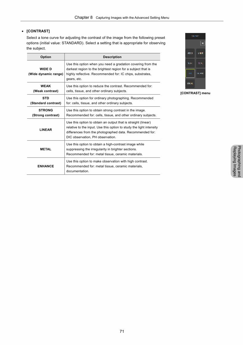
Chapter 8 Capturing Images with the Advanced Setting Menu
71
Photographing and
Replaying Im
ages
[CONTRAST]
Select a tone curve for adjusting the contrast of the image from the following preset
options (initial value: STANDARD). Select a setting that is appropriate for observing
the subject.
Option Description
WIDE D
(Wide dynamic range)
Use this option when you need a gradation covering from the
darkest region to the brightest region for a subject that is
highly reflective. Recommended for: IC chips, substrates,
gears, etc.
WEAK
(Weak contrast)
Use this option to reduce the contrast. Recommended for:
cells, tissue, and other ordinary subjects.
STD
(Standard contrast)
Use this option for ordinary photographing. Recommended
for: cells, tissue, and other ordinary subjects.
STRONG
(Strong contrast)
Use this option to obtain strong contrast in the image.
Recommended for: cells, tissue, and other ordinary subjects.
LINEAR
Use this option to obtain an output that is straight (linear)
relative to the input. Use this option to study the light intensity
differences from the photographed data. Recommended for:
DIC observation, PH observation.
METAL
Use this option to obtain a high-contrast image while
suppressing the irregularity in brighter sections.
Recommended for: metal tissue, ceramic materials.
ENHANCE
Use this option to make observation with high contrast.
Recommended for: metal tissue, ceramic materials,
documentation.
[CONTRAST] menu
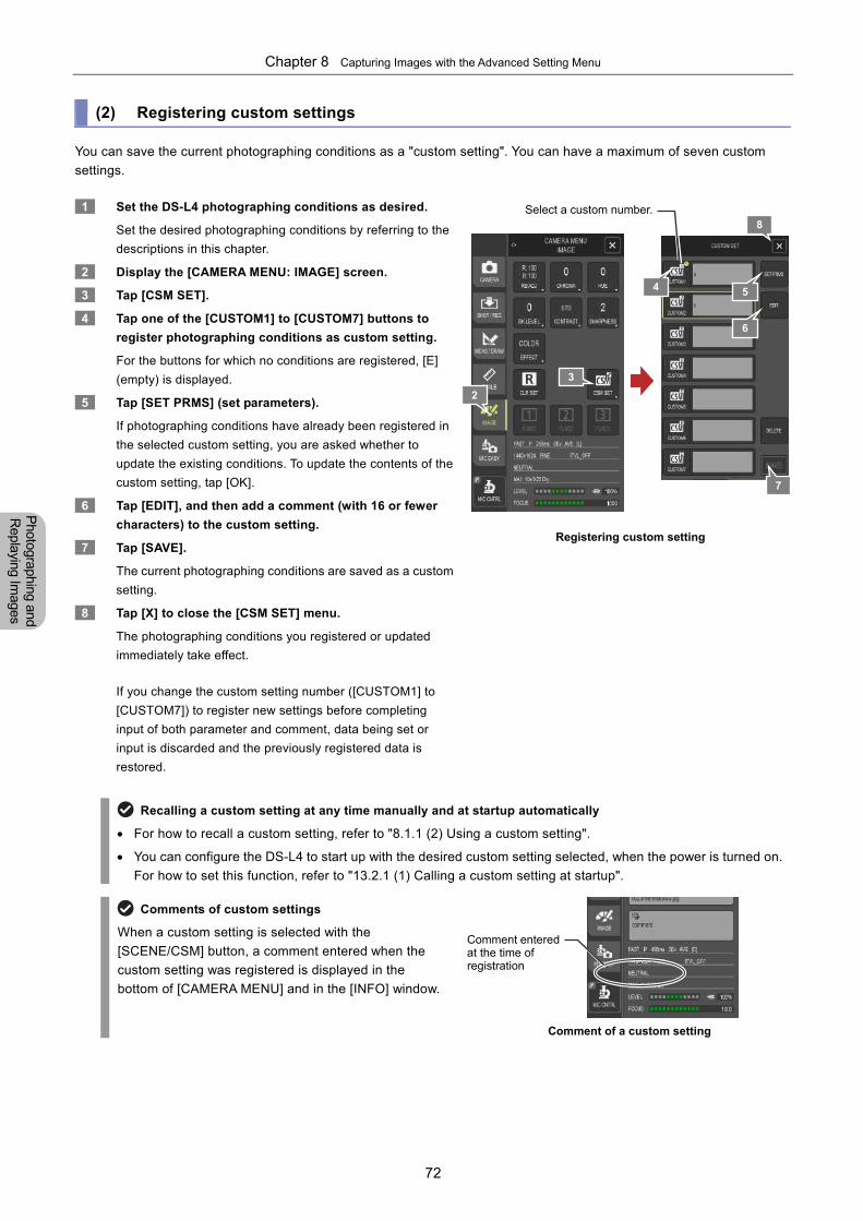
Chapter 8 Capturing Images with the Advanced Setting Menu
72
Photographing and
Replaying Im
ages
(2) Registering custom settings
You can save the current photographing conditions as a "custom setting". You can have a maximum of seven custom
settings.
1 Set the DS-L4 photographing conditions as desired.
Set the desired photographing conditions by referring to the
descriptions in this chapter.
2 Display the [CAMERA MENU: IMAGE] screen.
3 Tap [CSM SET].
4 Tap one of the [CUSTOM1] to [CUSTOM7] buttons to
register photographing conditions as custom setting.
For the buttons for which no conditions are registered, [E]
(empty) is displayed.
5 Tap [SET PRMS] (set parameters).
If photographing conditions have already been registered in
the selected custom setting, you are asked whether to
update the existing conditions. To update the contents of the
custom setting, tap [OK].
6 Tap [EDIT], and then add a comment (with 16 or fewer
characters) to the custom setting.
7 Tap [SAVE].
The current photographing conditions are saved as a custom
setting.
8 Tap [X] to close the [CSM SET] menu.
The photographing conditions you registered or updated
immediately take effect.
If you change the custom setting number ([CUSTOM1] to
[CUSTOM7]) to register new settings before completing
input of both parameter and comment, data being set or
input is discarded and the previously registered data is
restored.
Registering custom setting
Recalling a custom setting at any time manually and at startup automatically
For how to recall a custom setting, refer to "8.1.1 (2) Using a custom setting".
You can configure the DS-L4 to start up with the desired custom setting selected, when the power is turned on.
For how to set this function, refer to "13.2.1 (1) Calling a custom setting at startup".
Comments of custom settings
When a custom setting is selected with the
[SCENE/CSM] button, a comment entered when the
custom setting was registered is displayed in the
bottom of [CAMERA MENU] and in the [INFO] window.
Comment of a custom setting
2
3
4
7
Select a custom number.
Comment enteredat the time of registration
5
6
8
Chapter 8 Capturing Images with the Advanced Setting Menu
73
Photographing and
Replaying Im
ages
Photographing conditions registered as custom settings
Image mode (FULL or FAST)
Exposure mode (program AE, manual, or focus-priority AE)
Exposure time setting value
Camera gain setting value
Exposure compensation value
White balance
Metering mode and metering area (size and coordinates for custom setting)
Image adjustment settings (RB adjustment, chroma, hue, color effect, black level, contrast, and sharpness)
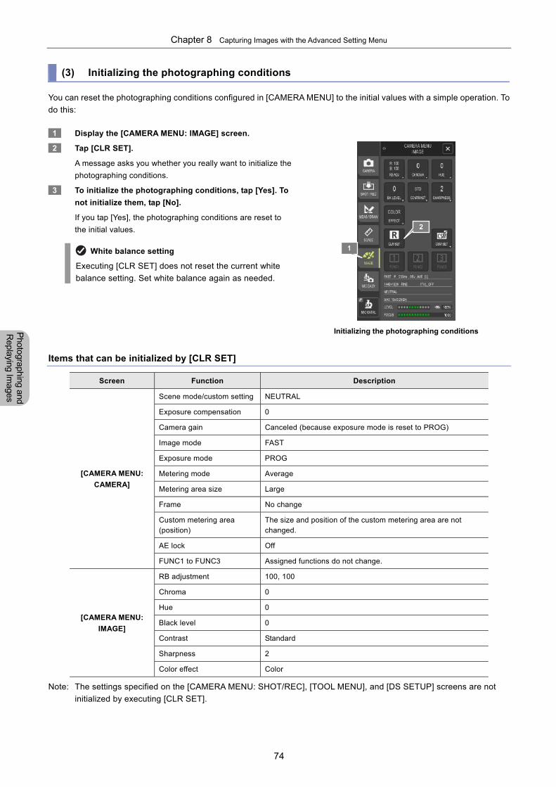
Chapter 8 Capturing Images with the Advanced Setting Menu
74
Photographing and
Replaying Im
ages
(3) Initializing the photographing conditions
You can reset the photographing conditions configured in [CAMERA MENU] to the initial values with a simple operation. To
do this:
1 Display the [CAMERA MENU: IMAGE] screen.
2 Tap [CLR SET].
A message asks you whether you really want to initialize the
photographing conditions.
3 To initialize the photographing conditions, tap [Yes]. To
not initialize them, tap [No].
If you tap [Yes], the photographing conditions are reset to
the initial values.
White balance setting
Executing [CLR SET] does not reset the current white
balance setting. Set white balance again as needed.
Initializing the photographing conditions Items that can be initialized by [CLR SET]
Screen Function Description
[CAMERA MENU:
CAMERA]
Scene mode/custom setting NEUTRAL
Exposure compensation 0
Camera gain Canceled (because exposure mode is reset to PROG)
Image mode FAST
Exposure mode PROG
Metering mode Average
Metering area size Large
Frame No change
Custom metering area (position)
The size and position of the custom metering area are not changed.
AE lock Off
FUNC1 to FUNC3 Assigned functions do not change.
[CAMERA MENU:
IMAGE]
RB adjustment 100, 100
Chroma 0
Hue 0
Black level 0
Contrast Standard
Sharpness 2
Color effect Color
Note: The settings specified on the [CAMERA MENU: SHOT/REC], [TOOL MENU], and [DS SETUP] screens are not
initialized by executing [CLR SET].
1
2
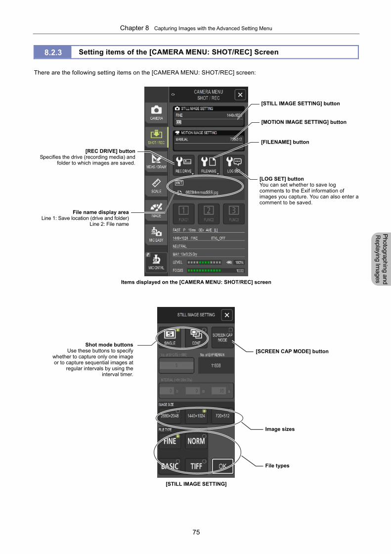
Chapter 8 Capturing Images with the Advanced Setting Menu
75
Photographing and
Replaying Im
ages
8.2.3 Setting items of the [CAMERA MENU: SHOT/REC] Screen
There are the following setting items on the [CAMERA MENU: SHOT/REC] screen:
Items displayed on the [CAMERA MENU: SHOT/REC] screen
[STILL IMAGE SETTING]
[REC DRIVE] buttonSpecifies the drive (recording media) and
folder to which images are saved.
Shot mode buttonsUse these buttons to specify
whether to capture only one image or to capture sequential images at
regular intervals by using the interval timer.
File name display areaLine 1: Save location (drive and folder)
Line 2: File name
[STILL IMAGE SETTING] button
[MOTION IMAGE SETTING] button
[LOG SET] buttonYou can set whether to save log comments to the Exif information of images you capture. You can also enter a comment to be saved.
[FILENAME] button
[SCREEN CAP MODE] button
Image sizes
File types
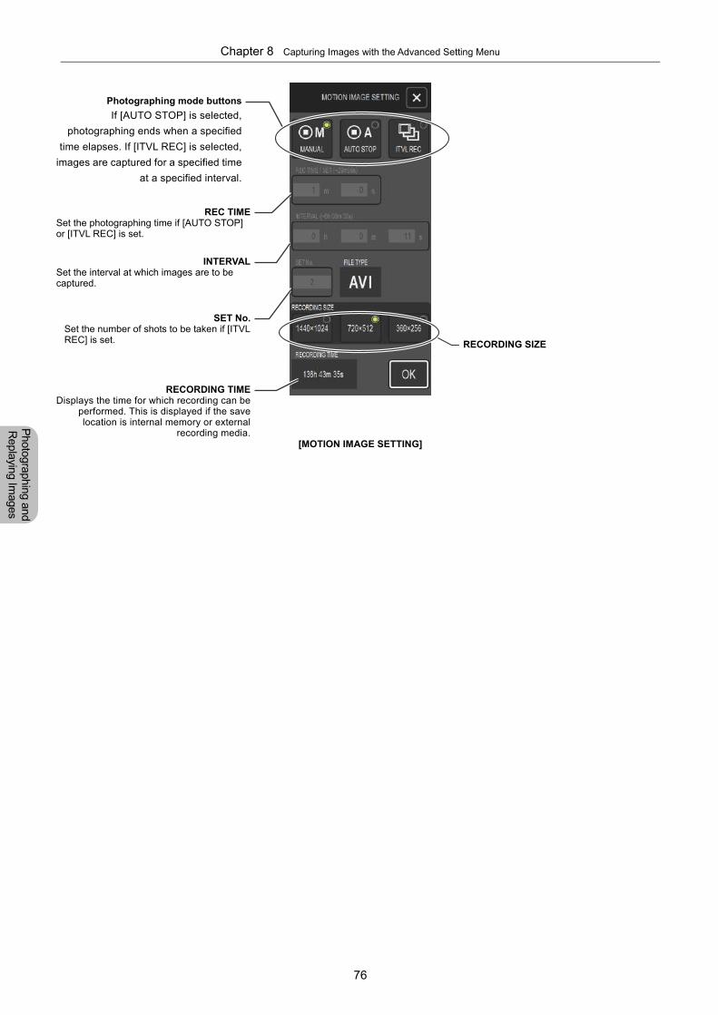
Chapter 8 Capturing Images with the Advanced Setting Menu
76
Photographing and
Replaying Im
ages
[MOTION IMAGE SETTING]
RECORDING SIZE
Photographing mode buttons
If [AUTO STOP] is selected,
photographing ends when a specified
time elapses. If [ITVL REC] is selected,
images are captured for a specified time
at a specified interval.
RECORDING TIMEDisplays the time for which recording can be
performed. This is displayed if the savelocation is internal memory or external
recording media.
REC TIMESet the photographing time if [AUTO STOP] or [ITVL REC] is set.
INTERVALSet the interval at which images are to be captured.
SET No.Set the number of shots to be taken if [ITVL REC] is set.
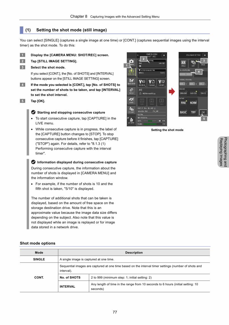
Chapter 8 Capturing Images with the Advanced Setting Menu
77
Photographing and
Replaying Im
ages
(1) Setting the shot mode (still image)
You can select [SINGLE] (captures a single image at one time) or [CONT.] (captures sequential images using the interval
timer) as the shot mode. To do this:
1 Display the [CAMERA MENU: SHOT/REC] screen.
2 Tap [STILL IMAGE SETTING].
3 Select the shot mode.
If you select [CONT.], the [No. of SHOTS] and [INTERVAL]
buttons appear on the [STILL IMAGE SETTING] screen.
4 If the mode you selected is [CONT.], tap [No. of SHOTS] to
set the number of shots to be taken, and tap [INTERVAL]
to set the shot interval.
5 Tap [OK].
Starting and stopping consecutive capture
To start consecutive capture, tap [CAPTURE] in the LIVE menu.
While consecutive capture is in progress, the label of the [CAPTURE] button changes to [STOP]. To stop consecutive capture before it finishes, tap [CAPTURE] ("STOP") again. For details, refer to "8.1.3 (1) Performing consecutive capture with the interval timer".
Information displayed during consecutive capture
During consecutive capture, the information about the number of shots is displayed in [CAMERA MENU] and the information window.
For example, if the number of shots is 10 and the fifth shot is taken, "5/10" is displayed.
The number of additional shots that can be taken is displayed, based on the amount of free space on the storage destination drive. Note that this is an approximate value because the image data size differs depending on the subject. Also note that this value is not displayed while an image is replayed or for image data stored in a network drive.
Setting the shot mode
Shot mode options
Mode Description
SINGLE A single image is captured at one time.
CONT.
Sequential images are captured at one time based on the interval timer settings (number of shots and
interval).
No. of SHOTS 2 to 999 (minimum step: 1; initial setting: 2)
INTERVAL Any length of time in the range from 10 seconds to 6 hours (initial setting: 10
seconds)
1
32
4
5
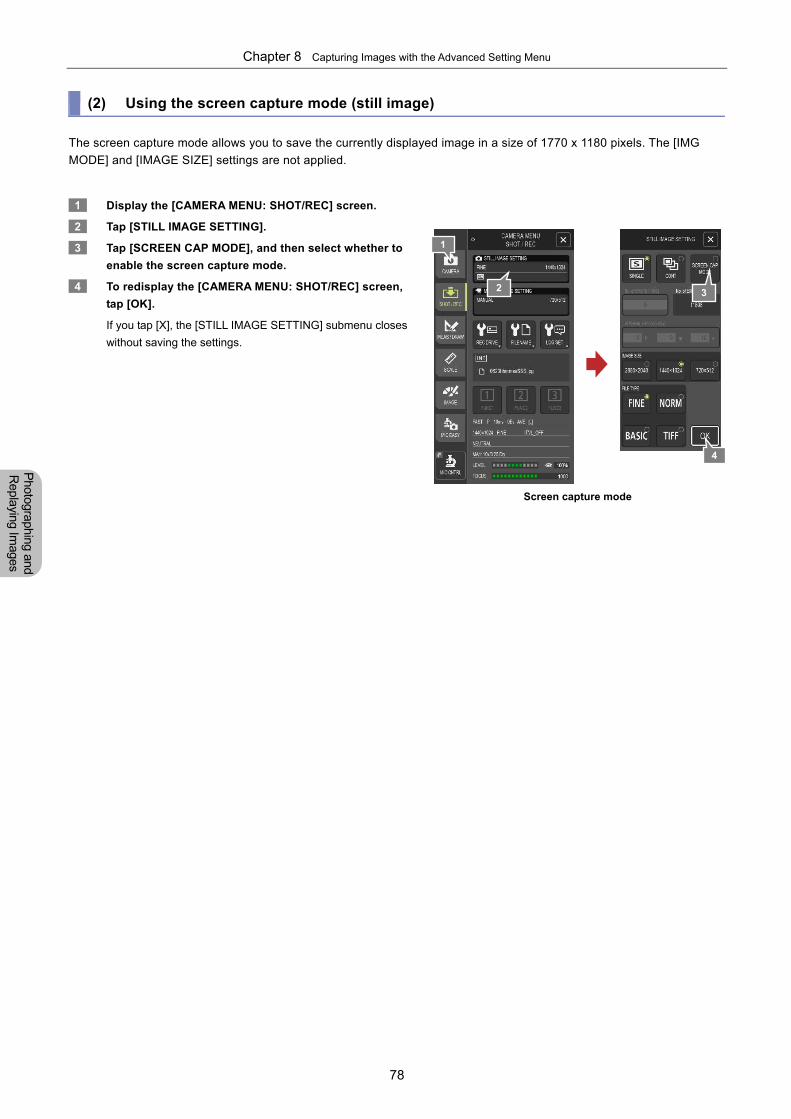
Chapter 8 Capturing Images with the Advanced Setting Menu
78
Photographing and
Replaying Im
ages
(2) Using the screen capture mode (still image)
The screen capture mode allows you to save the currently displayed image in a size of 1770 x 1180 pixels. The [IMG
MODE] and [IMAGE SIZE] settings are not applied.
1 Display the [CAMERA MENU: SHOT/REC] screen.
2 Tap [STILL IMAGE SETTING].
3 Tap [SCREEN CAP MODE], and then select whether to
enable the screen capture mode.
4 To redisplay the [CAMERA MENU: SHOT/REC] screen,
tap [OK].
If you tap [X], the [STILL IMAGE SETTING] submenu closes
without saving the settings.
Screen capture mode
1
2 3
4
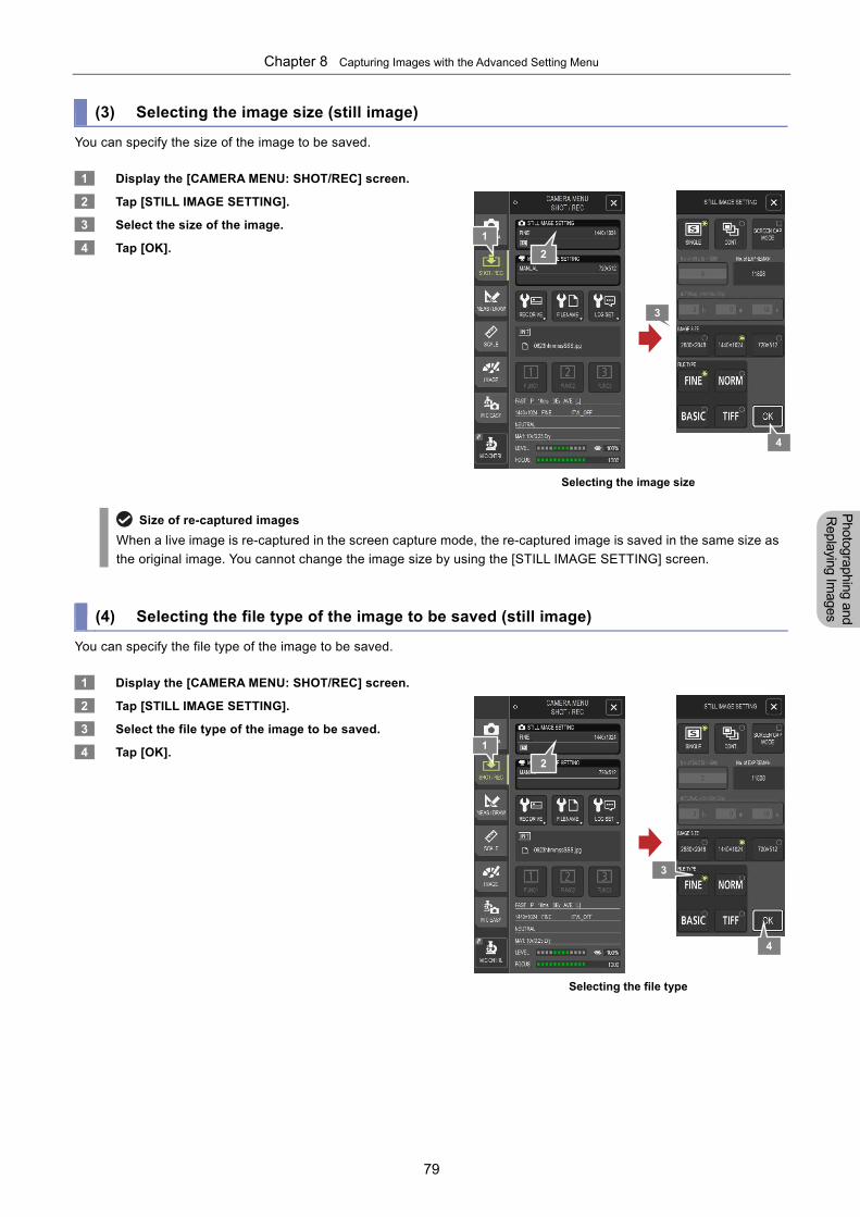
Chapter 8 Capturing Images with the Advanced Setting Menu
79
Photographing and
Replaying Im
ages
(3) Selecting the image size (still image)
You can specify the size of the image to be saved.
1 Display the [CAMERA MENU: SHOT/REC] screen.
2 Tap [STILL IMAGE SETTING].
3 Select the size of the image.
4 Tap [OK].
Selecting the image size
Size of re-captured images
When a live image is re-captured in the screen capture mode, the re-captured image is saved in the same size as
the original image. You cannot change the image size by using the [STILL IMAGE SETTING] screen.
(4) Selecting the file type of the image to be saved (still image)
You can specify the file type of the image to be saved.
1 Display the [CAMERA MENU: SHOT/REC] screen.
2 Tap [STILL IMAGE SETTING].
3 Select the file type of the image to be saved.
4 Tap [OK].
Selecting the file type
1
2
3
4
2
1
3
4
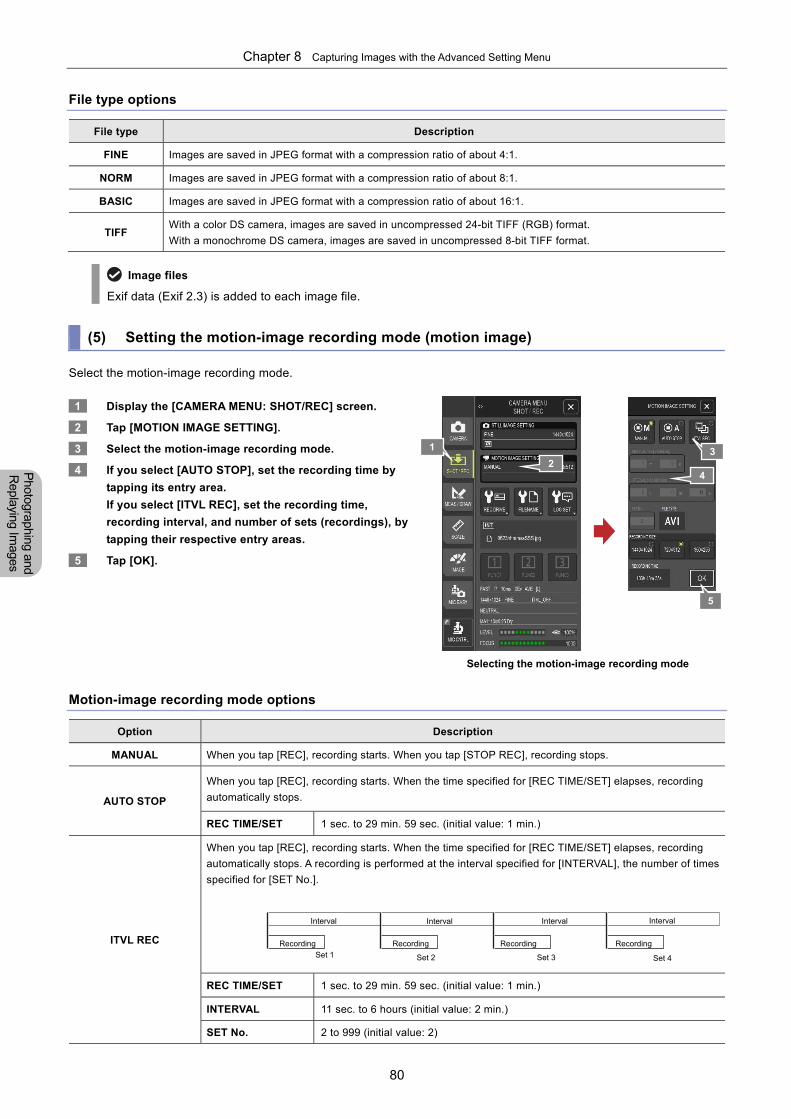
Chapter 8 Capturing Images with the Advanced Setting Menu
80
Photographing and
Replaying Im
ages
File type options
File type Description
FINE Images are saved in JPEG format with a compression ratio of about 4:1.
NORM Images are saved in JPEG format with a compression ratio of about 8:1.
BASIC Images are saved in JPEG format with a compression ratio of about 16:1.
TIFF With a color DS camera, images are saved in uncompressed 24-bit TIFF (RGB) format.
With a monochrome DS camera, images are saved in uncompressed 8-bit TIFF format.
Image files
Exif data (Exif 2.3) is added to each image file.
(5) Setting the motion-image recording mode (motion image)
Select the motion-image recording mode.
1 Display the [CAMERA MENU: SHOT/REC] screen.
2 Tap [MOTION IMAGE SETTING].
3 Select the motion-image recording mode.
4 If you select [AUTO STOP], set the recording time by
tapping its entry area.
If you select [ITVL REC], set the recording time,
recording interval, and number of sets (recordings), by
tapping their respective entry areas.
5 Tap [OK].
Selecting the motion-image recording mode
Motion-image recording mode options
Option Description
MANUAL When you tap [REC], recording starts. When you tap [STOP REC], recording stops.
AUTO STOP
When you tap [REC], recording starts. When the time specified for [REC TIME/SET] elapses, recording
automatically stops.
REC TIME/SET 1 sec. to 29 min. 59 sec. (initial value: 1 min.)
ITVL REC
When you tap [REC], recording starts. When the time specified for [REC TIME/SET] elapses, recording
automatically stops. A recording is performed at the interval specified for [INTERVAL], the number of times
specified for [SET No.].
REC TIME/SET 1 sec. to 29 min. 59 sec. (initial value: 1 min.)
INTERVAL 11 sec. to 6 hours (initial value: 2 min.)
SET No. 2 to 999 (initial value: 2)
1
2 3
4
Interval Interval Interval
Recording Recording Recording
Interval
Recording
Set 1 Set 2 Set 3 Set 4
5
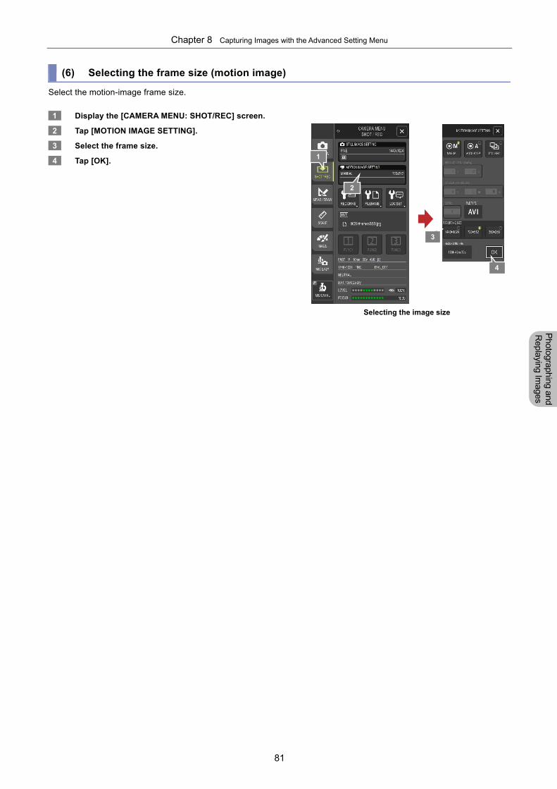
Chapter 8 Capturing Images with the Advanced Setting Menu
81
Photographing and
Replaying Im
ages
(6) Selecting the frame size (motion image)
Select the motion-image frame size.
1 Display the [CAMERA MENU: SHOT/REC] screen.
2 Tap [MOTION IMAGE SETTING].
3 Select the frame size.
4 Tap [OK].
Selecting the image size
2
3
4
1
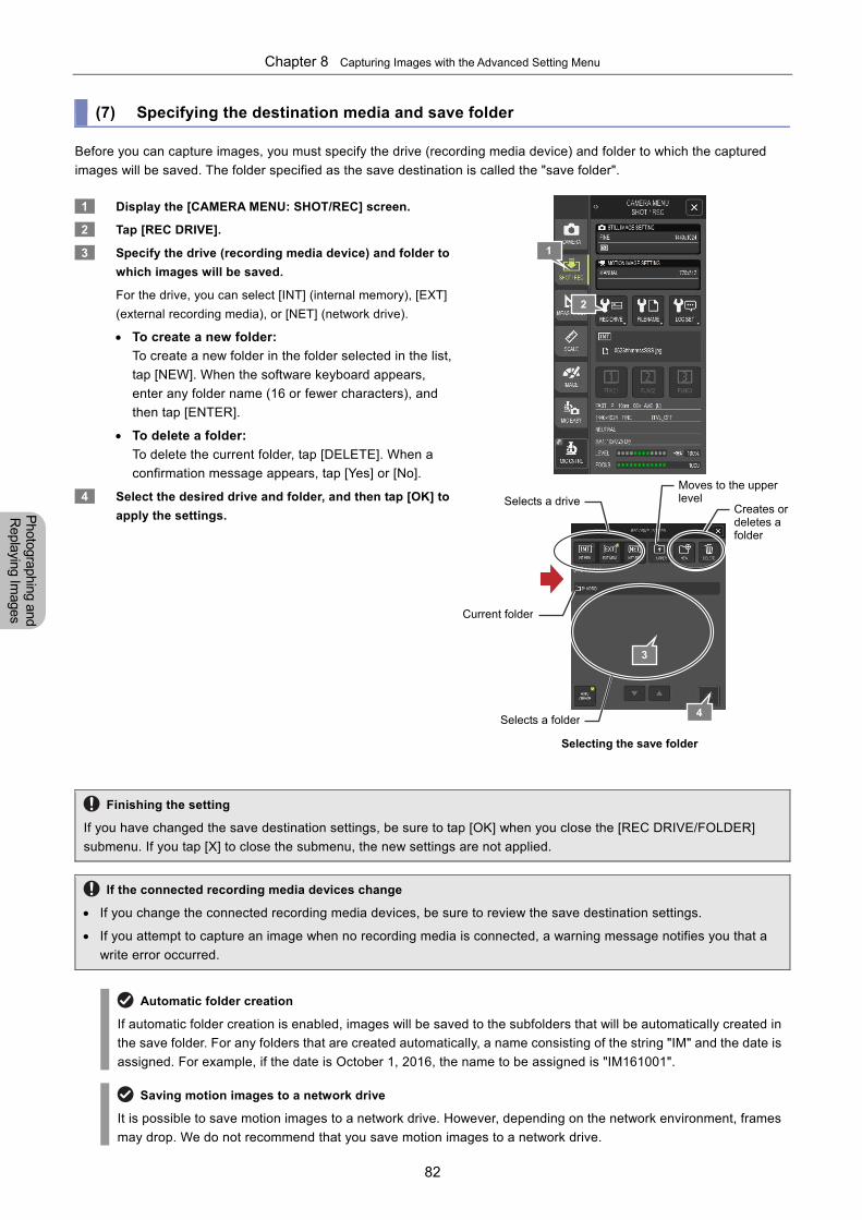
Chapter 8 Capturing Images with the Advanced Setting Menu
82
Photographing and
Replaying Im
ages
(7) Specifying the destination media and save folder
Before you can capture images, you must specify the drive (recording media device) and folder to which the captured
images will be saved. The folder specified as the save destination is called the "save folder".
1 Display the [CAMERA MENU: SHOT/REC] screen.
2 Tap [REC DRIVE].
3 Specify the drive (recording media device) and folder to
which images will be saved.
For the drive, you can select [INT] (internal memory), [EXT]
(external recording media), or [NET] (network drive).
To create a new folder:
To create a new folder in the folder selected in the list,
tap [NEW]. When the software keyboard appears,
enter any folder name (16 or fewer characters), and
then tap [ENTER].
To delete a folder:
To delete the current folder, tap [DELETE]. When a
confirmation message appears, tap [Yes] or [No].
4 Select the desired drive and folder, and then tap [OK] to
apply the settings.
Selecting the save folder
Finishing the setting
If you have changed the save destination settings, be sure to tap [OK] when you close the [REC DRIVE/FOLDER]
submenu. If you tap [X] to close the submenu, the new settings are not applied.
If the connected recording media devices change
If you change the connected recording media devices, be sure to review the save destination settings.
If you attempt to capture an image when no recording media is connected, a warning message notifies you that a
write error occurred.
Automatic folder creation
If automatic folder creation is enabled, images will be saved to the subfolders that will be automatically created in
the save folder. For any folders that are created automatically, a name consisting of the string "IM" and the date is
assigned. For example, if the date is October 1, 2016, the name to be assigned is "IM161001".
Saving motion images to a network drive
It is possible to save motion images to a network drive. However, depending on the network environment, frames
may drop. We do not recommend that you save motion images to a network drive.
2
Selects a driveCreates or deletes a folder
Selects a folder
3
1
4
Moves to the upper level
Current folder
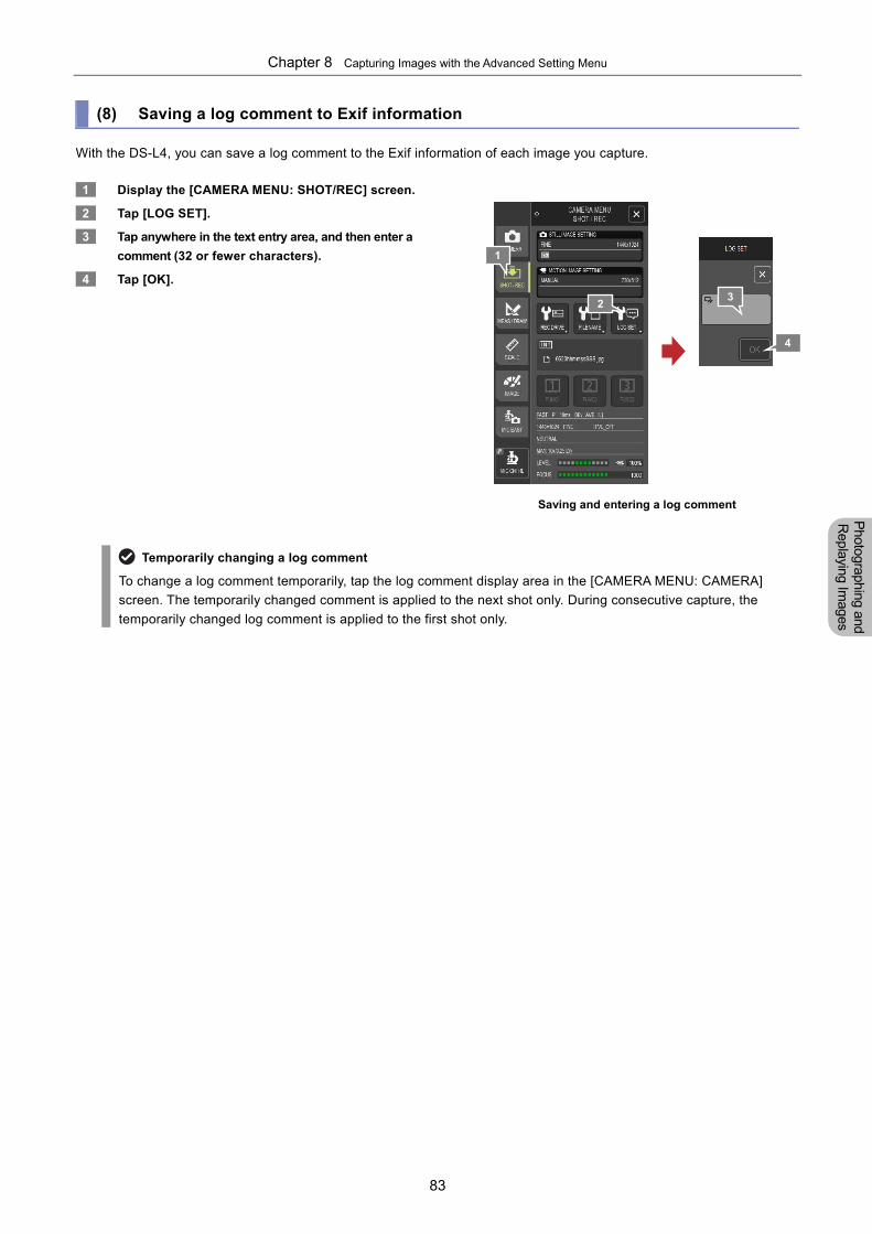
Chapter 8 Capturing Images with the Advanced Setting Menu
83
Photographing and
Replaying Im
ages
(8) Saving a log comment to Exif information
With the DS-L4, you can save a log comment to the Exif information of each image you capture.
1 Display the [CAMERA MENU: SHOT/REC] screen.
2 Tap [LOG SET].
3 Tap anywhere in the text entry area, and then enter a
comment (32 or fewer characters).
4 Tap [OK].
Saving and entering a log comment
Temporarily changing a log comment
To change a log comment temporarily, tap the log comment display area in the [CAMERA MENU: CAMERA]
screen. The temporarily changed comment is applied to the next shot only. During consecutive capture, the
temporarily changed log comment is applied to the first shot only.
1
2 3
4
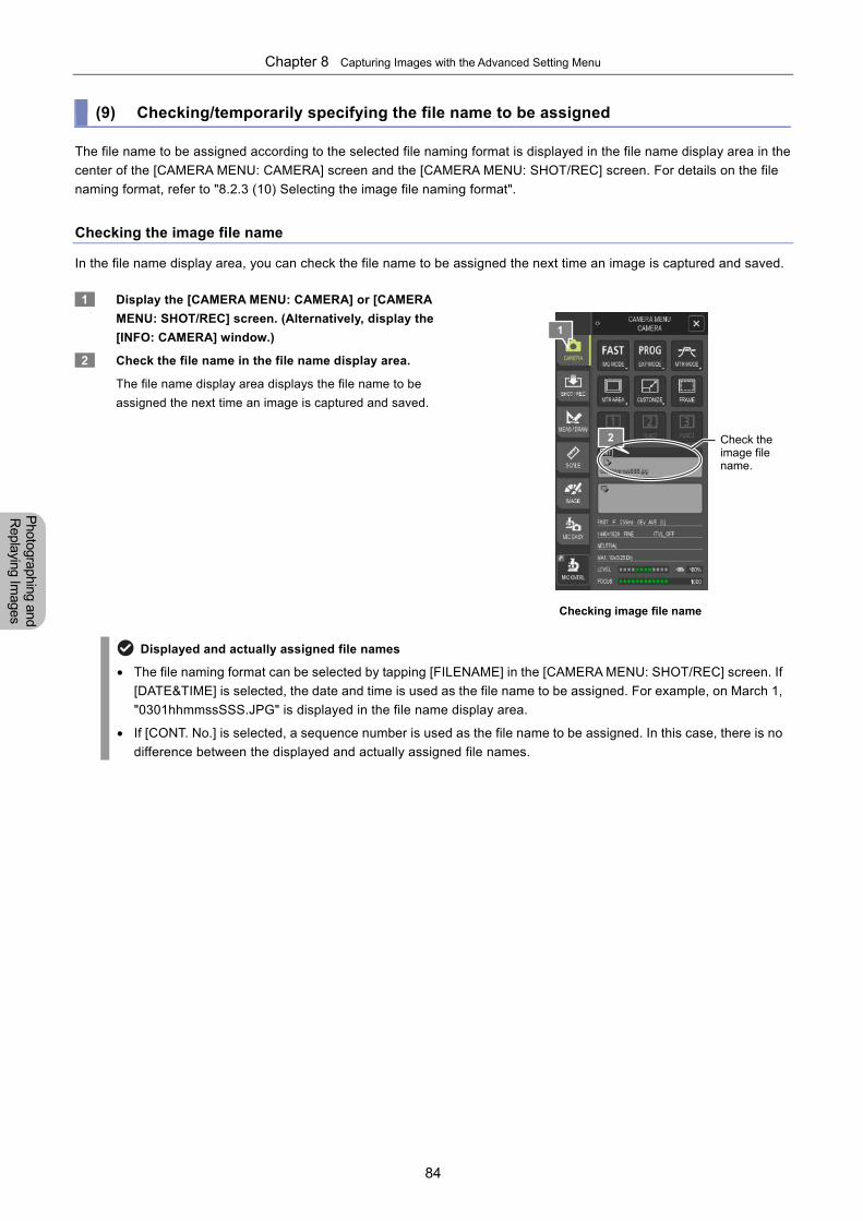
Chapter 8 Capturing Images with the Advanced Setting Menu
84
Photographing and
Replaying Im
ages
(9) Checking/temporarily specifying the file name to be assigned
The file name to be assigned according to the selected file naming format is displayed in the file name display area in the
center of the [CAMERA MENU: CAMERA] screen and the [CAMERA MENU: SHOT/REC] screen. For details on the file
naming format, refer to "8.2.3 (10) Selecting the image file naming format".
Checking the image file name
In the file name display area, you can check the file name to be assigned the next time an image is captured and saved.
1 Display the [CAMERA MENU: CAMERA] or [CAMERA
MENU: SHOT/REC] screen. (Alternatively, display the
[INFO: CAMERA] window.)
2 Check the file name in the file name display area.
The file name display area displays the file name to be
assigned the next time an image is captured and saved.
Checking image file name
Displayed and actually assigned file names
The file naming format can be selected by tapping [FILENAME] in the [CAMERA MENU: SHOT/REC] screen. If
[DATE&TIME] is selected, the date and time is used as the file name to be assigned. For example, on March 1,
"0301hhmmssSSS.JPG" is displayed in the file name display area.
If [CONT. No.] is selected, a sequence number is used as the file name to be assigned. In this case, there is no
difference between the displayed and actually assigned file names.
1
2 Check the image file name.
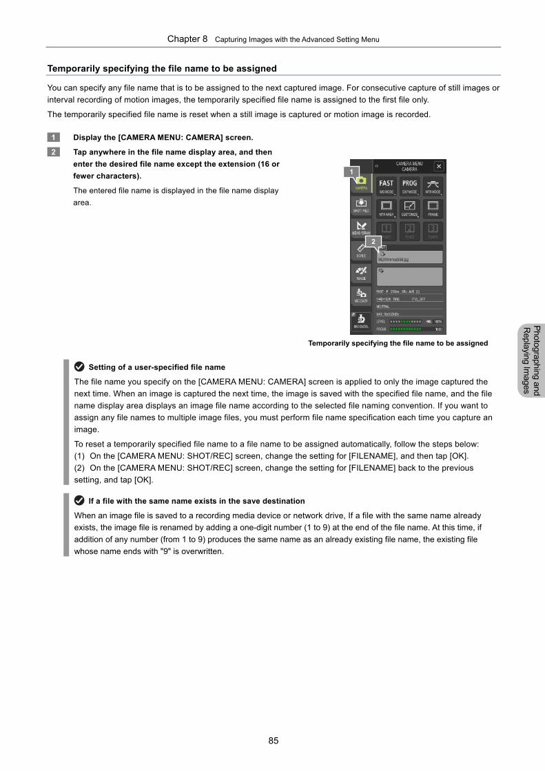
Chapter 8 Capturing Images with the Advanced Setting Menu
85
Photographing and
Replaying Im
ages
Temporarily specifying the file name to be assigned
You can specify any file name that is to be assigned to the next captured image. For consecutive capture of still images or
interval recording of motion images, the temporarily specified file name is assigned to the first file only.
The temporarily specified file name is reset when a still image is captured or motion image is recorded.
1 Display the [CAMERA MENU: CAMERA] screen.
2 Tap anywhere in the file name display area, and then
enter the desired file name except the extension (16 or
fewer characters).
The entered file name is displayed in the file name display
area.
Temporarily specifying the file name to be assigned
Setting of a user-specified file name
The file name you specify on the [CAMERA MENU: CAMERA] screen is applied to only the image captured the
next time. When an image is captured the next time, the image is saved with the specified file name, and the file
name display area displays an image file name according to the selected file naming convention. If you want to
assign any file names to multiple image files, you must perform file name specification each time you capture an
image.
To reset a temporarily specified file name to a file name to be assigned automatically, follow the steps below:
(1) On the [CAMERA MENU: SHOT/REC] screen, change the setting for [FILENAME], and then tap [OK].
(2) On the [CAMERA MENU: SHOT/REC] screen, change the setting for [FILENAME] back to the previous
setting, and tap [OK].
If a file with the same name exists in the save destination
When an image file is saved to a recording media device or network drive, If a file with the same name already
exists, the image file is renamed by adding a one-digit number (1 to 9) at the end of the file name. At this time, if
addition of any number (from 1 to 9) produces the same name as an already existing file name, the existing file
whose name ends with "9" is overwritten.
1
2
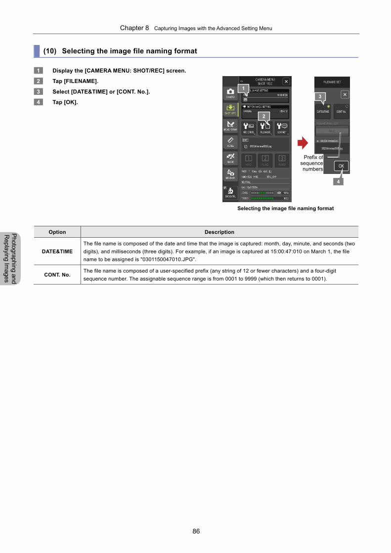
Chapter 8 Capturing Images with the Advanced Setting Menu
86
Photographing and
Replaying Im
ages
(10) Selecting the image file naming format
1 Display the [CAMERA MENU: SHOT/REC] screen.
2 Tap [FILENAME].
3 Select [DATE&TIME] or [CONT. No.].
4 Tap [OK].
Selecting the image file naming format
Option Description
DATE&TIME
The file name is composed of the date and time that the image is captured: month, day, minute, and seconds (two
digits), and milliseconds (three digits). For example, if an image is captured at 15:00:47:010 on March 1, the file
name to be assigned is "0301150047010.JPG".
CONT. No. The file name is composed of a user-specified prefix (any string of 12 or fewer characters) and a four-digit
sequence number. The assignable sequence range is from 0001 to 9999 (which then returns to 0001).
1
2
3
4
Prefix ofsequencenumbers
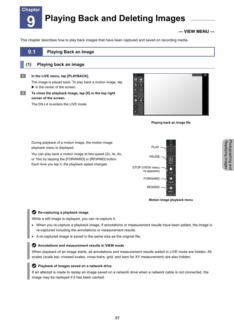
Chapter 9 Replaying and Deleting Images
87
Photographing and
Replaying Im
ages
9 Playing Back and Deleting Images
— VIEW MENU —
This chapter describes how to play back images that have been captured and saved on recording media.
9.1 Playing Back an Image
(1) Playing back an image
1 In the LIVE menu, tap [PLAYBACK].
The image is played back. To play back a motion image, tap
in the center of the screen.
2 To close the playback image, tap [X] in the top right
corner of the screen.
The DS-L4 re-enters the LIVE mode.
Playing back an image file
During playback of a motion image, the motion image
playback menu is displayed.
You can play back a motion image at fast speed (2x, 4x, 8x,
or 16x) by tapping the [FORWARD] or [REWIND] button.
Each time you tap it, the playback speed changes.
Motion image playback menu
Re-capturing a playback image
While a still image is replayed, you can re-capture it.
When you re-capture a playback image, if annotations or measurement results have been added, the image is
re-captured including the annotations or measurement results.
A re-captured image is saved in the same size as the original file.
Annotations and measurement results in VIEW mode
When playback of an image starts, all annotations and measurement results added in LIVE mode are hidden. All
scales (scale bar, crossed scales, cross-hairs, grid, and bars for XY measurement) are also hidden.
Playback of images saved on a network drive
If an attempt is made to replay an image saved on a network drive when a network cable is not connected, the
image may be replayed if it has been cached.
Playing Back and Deleting Images Chapter
9
PAUSE
STOP (VIEW menu re-appears)
FORWARD
PLAY
REWIND
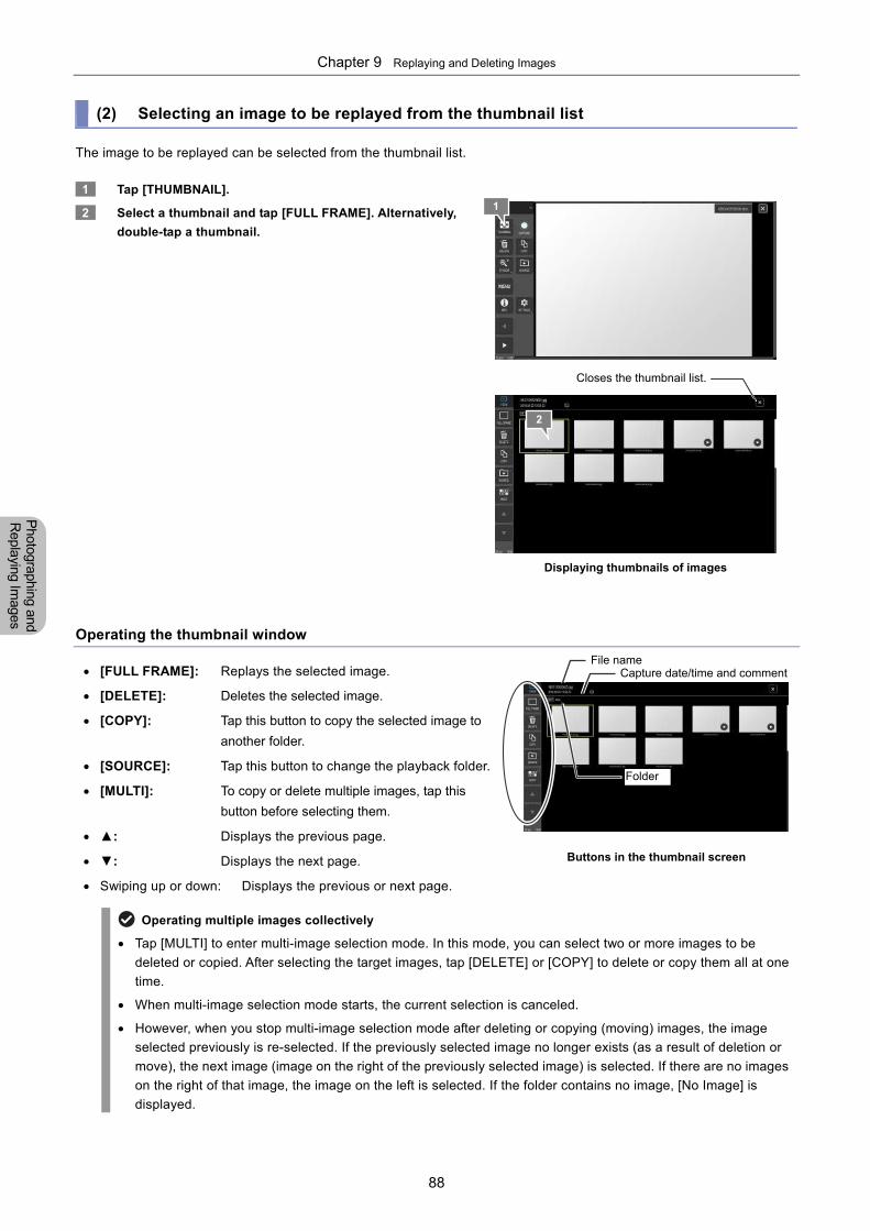
Chapter 9 Replaying and Deleting Images
88
Photographing and
Replaying Im
ages
(2) Selecting an image to be replayed from the thumbnail list
The image to be replayed can be selected from the thumbnail list.
1 Tap [THUMBNAIL].
2 Select a thumbnail and tap [FULL FRAME]. Alternatively,
double-tap a thumbnail.
Displaying thumbnails of images
Operating the thumbnail window
[FULL FRAME]: Replays the selected image.
[DELETE]: Deletes the selected image.
[COPY]: Tap this button to copy the selected image to
another folder.
[SOURCE]: Tap this button to change the playback folder.
[MULTI]: To copy or delete multiple images, tap this
button before selecting them.
▲: Displays the previous page.
▼: Displays the next page.
Swiping up or down: Displays the previous or next page.
Buttons in the thumbnail screen
Operating multiple images collectively
Tap [MULTI] to enter multi-image selection mode. In this mode, you can select two or more images to be
deleted or copied. After selecting the target images, tap [DELETE] or [COPY] to delete or copy them all at one
time.
When multi-image selection mode starts, the current selection is canceled.
However, when you stop multi-image selection mode after deleting or copying (moving) images, the image
selected previously is re-selected. If the previously selected image no longer exists (as a result of deletion or
move), the next image (image on the right of the previously selected image) is selected. If there are no images
on the right of that image, the image on the left is selected. If the folder contains no image, [No Image] is
displayed.
1
2
Closes the thumbnail list.
File name Capture date/time and comment
Folder
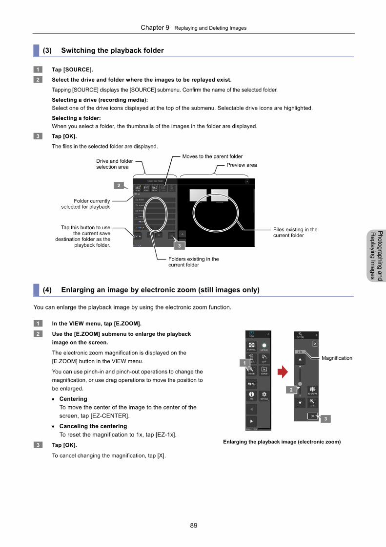
Chapter 9 Replaying and Deleting Images
89
Photographing and
Replaying Im
ages
(3) Switching the playback folder
1 Tap [SOURCE].
2 Select the drive and folder where the images to be replayed exist.
Tapping [SOURCE] displays the [SOURCE] submenu. Confirm the name of the selected folder.
Selecting a drive (recording media):
Select one of the drive icons displayed at the top of the submenu. Selectable drive icons are highlighted.
Selecting a folder:
When you select a folder, the thumbnails of the images in the folder are displayed.
3 Tap [OK].
The files in the selected folder are displayed.
(4) Enlarging an image by electronic zoom (still images only)
You can enlarge the playback image by using the electronic zoom function.
1 In the VIEW menu, tap [E.ZOOM].
2 Use the [E.ZOOM] submenu to enlarge the playback
image on the screen.
The electronic zoom magnification is displayed on the
[E.ZOOM] button in the VIEW menu.
You can use pinch-in and pinch-out operations to change the
magnification, or use drag operations to move the position to
be enlarged.
Centering
To move the center of the image to the center of the
screen, tap [EZ-CENTER].
Canceling the centering
To reset the magnification to 1x, tap [EZ-1x].
3 Tap [OK].
To cancel changing the magnification, tap [X].
Enlarging the playback image (electronic zoom)
3
1 Magnification
2
2
Tap this button to usethe current save
destination folder as theplayback folder.
Drive and folder selection area
Folders existing in the current folder
Preview area
3
Moves to the parent folder
Files existing in the current folder
Folder currentlyselected for playback
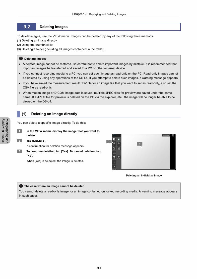
Chapter 9 Replaying and Deleting Images
90
Photographing and
Replaying Im
ages
9.2 Deleting Images
To delete images, use the VIEW menu. Images can be deleted by any of the following three methods.
(1) Deleting an image directly
(2) Using the thumbnail list
(3) Deleting a folder (including all images contained in the folder)
Deleting images
A deleted image cannot be restored. Be careful not to delete important images by mistake. It is recommended that
important images be transferred and saved to a PC or other external device.
If you connect recording media to a PC, you can set each image as read-only on the PC. Read-only images cannot
be deleted by using any operations of the DS-L4. If you attempt to delete such images, a warning message appears.
If you have saved the measurement result CSV file for an image file that you want to set as read-only, also set the
CSV file as read-only.
When motion image or DICOM image data is saved, multiple JPEG files for preview are saved under the same
name. If a JPEG file for preview is deleted on the PC via the explorer, etc., the image will no longer be able to be
viewed on the DS-L4.
(1) Deleting an image directly
You can delete a specific image directly. To do this:
1 In the VIEW menu, display the image that you want to
delete.
2 Tap [DELETE].
A confirmation for deletion message appears.
3 To continue deletion, tap [Yes]. To cancel deletion, tap
[No].
When [Yes] is selected, the image is deleted.
Deleting an individual image
The case where an image cannot be deleted
You cannot delete a read-only image, or an image contained on locked recording media. A warning message appears
in such cases.
21
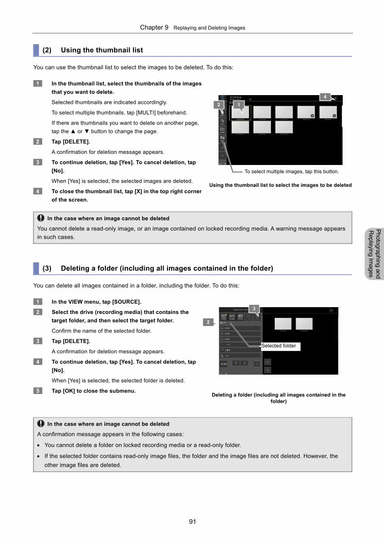
Chapter 9 Replaying and Deleting Images
91
Photographing and
Replaying Im
ages
(2) Using the thumbnail list
You can use the thumbnail list to select the images to be deleted. To do this:
1 In the thumbnail list, select the thumbnails of the images
that you want to delete.
Selected thumbnails are indicated accordingly.
To select multiple thumbnails, tap [MULTI] beforehand.
If there are thumbnails you want to delete on another page,
tap the ▲ or ▼ button to change the page.
2 Tap [DELETE].
A confirmation for deletion message appears.
3 To continue deletion, tap [Yes]. To cancel deletion, tap
[No].
When [Yes] is selected, the selected images are deleted.
4 To close the thumbnail list, tap [X] in the top right corner
of the screen.
Using the thumbnail list to select the images to be deleted
In the case where an image cannot be deleted
You cannot delete a read-only image, or an image contained on locked recording media. A warning message appears
in such cases.
(3) Deleting a folder (including all images contained in the folder)
You can delete all images contained in a folder, including the folder. To do this:
1 In the VIEW menu, tap [SOURCE].
2 Select the drive (recording media) that contains the
target folder, and then select the target folder.
Confirm the name of the selected folder.
3 Tap [DELETE].
A confirmation for deletion message appears.
4 To continue deletion, tap [Yes]. To cancel deletion, tap
[No].
When [Yes] is selected, the selected folder is deleted.
5 Tap [OK] to close the submenu.
Deleting a folder (including all images contained in the folder)
In the case where an image cannot be deleted
A confirmation message appears in the following cases:
You cannot delete a folder on locked recording media or a read-only folder.
If the selected folder contains read-only image files, the folder and the image files are not deleted. However, the
other image files are deleted.
1 2
4
3
To select multiple images, tap this button.
2
Selected folder
Chapter 9 Replaying and Deleting Images
92
Photographing and
Replaying Im
ages
Chapter 10 Preparation for Using the Annotation Function and Measurement Function
93
Scale, A
nnotation,
and Me
asurement
Functions
Part 4
Scale, Annotation, and Measurement Functions This part describes how to perform operations when using the scale function, annotation function, and measurement
function of the DS-L4.
This part consists of the following chapters:
Chapter 10 Preparation for Using the Scale, Annotation, and Measurement Functions
Chapter 11 Adding scales and annotations to images
Chapter 12 On-Screen Measurement
This chapter provides notes on, and describes the settings required for, using the annotation and measurement functions.
Chapter 10 Preparation for Using the Annotation Function and Measurement Function
94
Scale, A
nnotation,
and Me
asurement
Functions
10 Preparation for Using the Scale, Annotation, and Measurement Functions
10.1 Before Use
With the DS-L4, the following functions can be used for images:
Displaying scales
A variety of scales can be displayed on a live image or playback image. The scales that can be displayed include a
scale bar, crossed scales, cross-hairs, grid, and bars for XY measurement. Use the [SCALE] menu to operate these
scales. Unlike annotations and measurement results, the user can select the types of scales to be embedded in image
files.
Adding annotations
You can add annotations to a live or playback image. The annotations that can be added include arbitrary text, straight
lines, arrows, free-hand lines, and markers (numbers). Use the [MEAS/DRAW] menu to perform measurement.
Measurement function
You can measure the approximate length, angle, and diameter of an object in a live or playback image. Use the
[MEAS/DRAW] menu to perform measurement.
10.1.1 Notes on Annotation and Measurement Functions
Notes on scale, annotation, and measurement functions
Note the following when you use the scale, annotation, and measurement functions.
Calibration: Before you use annotation and measurement functions to measure an object, be sure to check the calibration setting. The DS-L4 provides two calibration modes: OPTICAL and MANUAL. Select one of these calibration modes.
- Normally, select OPTICAL. In this case, the measurement scale calculated from the magnification of the optical device is applied.
- Select MANUAL only when you want to perform measurement based on a specific measurement scale.
Switching of the calibration setting: Switching of the calibration setting affects the annotation and measurement functions as follows:
- For the scales (scale bar, crossed scales, cross-hairs, and bars for XY measurement), the values based on the
selected calibration mode are displayed.
- For the measurement results, the values based on the selected calibration mode are displayed.
- For the annotations, the displayed information does not change.
Annotations and measurement results for a playback image:
- While you are viewing an image saved in TIFF or JPEG format, if you display a scale or perform measurement, the unit and calibration settings that were specified when the image was saved are applied.
- You cannot add annotations or perform measurement for the motion image that is being replayed. (You cannot perform these operations even when you freeze the motion image.)
Precision: Measurement of the DS-L4 is approximate. Precision cannot be guaranteed.
Electronic Zooming:
Although electronic zoom enlarges an image, it does not enlarge scales. When you swipe to move an enlarged
image, the displayed scales do not move together with the image.
Preparation for Using the Scale, Annotation, and Measurement Functions
Chapter
10
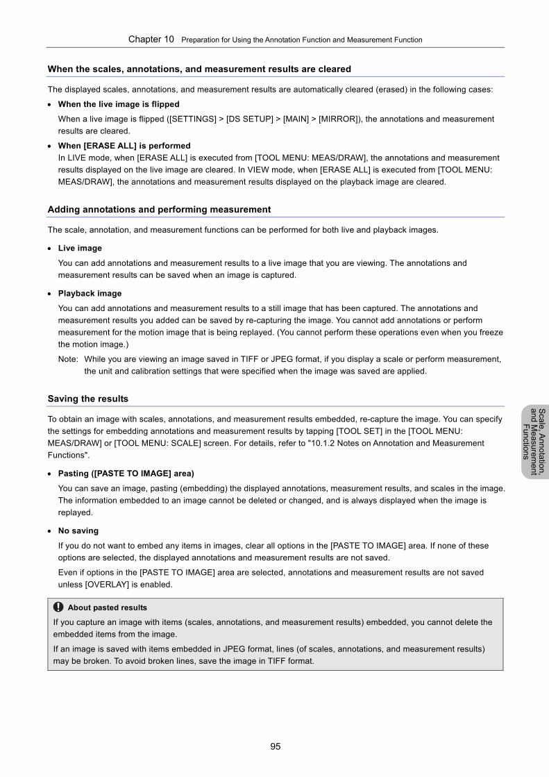
Chapter 10 Preparation for Using the Annotation Function and Measurement Function
95
Scale, A
nnotation,
and Me
asurement
Functions
When the scales, annotations, and measurement results are cleared
The displayed scales, annotations, and measurement results are automatically cleared (erased) in the following cases:
When the live image is flipped
When a live image is flipped ([SETTINGS] > [DS SETUP] > [MAIN] > [MIRROR]), the annotations and measurement
results are cleared.
When [ERASE ALL] is performed
In LIVE mode, when [ERASE ALL] is executed from [TOOL MENU: MEAS/DRAW], the annotations and measurement
results displayed on the live image are cleared. In VIEW mode, when [ERASE ALL] is executed from [TOOL MENU:
MEAS/DRAW], the annotations and measurement results displayed on the playback image are cleared.
Adding annotations and performing measurement
The scale, annotation, and measurement functions can be performed for both live and playback images.
Live image
You can add annotations and measurement results to a live image that you are viewing. The annotations and
measurement results can be saved when an image is captured.
Playback image
You can add annotations and measurement results to a still image that has been captured. The annotations and
measurement results you added can be saved by re-capturing the image. You cannot add annotations or perform
measurement for the motion image that is being replayed. (You cannot perform these operations even when you freeze
the motion image.)
Note: While you are viewing an image saved in TIFF or JPEG format, if you display a scale or perform measurement,
the unit and calibration settings that were specified when the image was saved are applied.
Saving the results
To obtain an image with scales, annotations, and measurement results embedded, re-capture the image. You can specify
the settings for embedding annotations and measurement results by tapping [TOOL SET] in the [TOOL MENU:
MEAS/DRAW] or [TOOL MENU: SCALE] screen. For details, refer to "10.1.2 Notes on Annotation and Measurement
Functions".
Pasting ([PASTE TO IMAGE] area)
You can save an image, pasting (embedding) the displayed annotations, measurement results, and scales in the image.
The information embedded to an image cannot be deleted or changed, and is always displayed when the image is
replayed.
No saving
If you do not want to embed any items in images, clear all options in the [PASTE TO IMAGE] area. If none of these
options are selected, the displayed annotations and measurement results are not saved.
Even if options in the [PASTE TO IMAGE] area are selected, annotations and measurement results are not saved
unless [OVERLAY] is enabled.
About pasted results
If you capture an image with items (scales, annotations, and measurement results) embedded, you cannot delete the
embedded items from the image.
If an image is saved with items embedded in JPEG format, lines (of scales, annotations, and measurement results)
may be broken. To avoid broken lines, save the image in TIFF format.
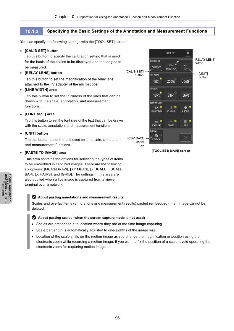
Chapter 10 Preparation for Using the Annotation Function and Measurement Function
96
Scale, A
nnotation,
and Me
asurement
Functions
10.1.2 Specifying the Basic Settings of the Annotation and Measurement Functions
You can specify the following settings with the [TOOL SET] screen.
[CALIB SET] button
Tap this button to specify the calibration setting that is used
for the basis of the scales to be displayed and the lengths to
be measured.
[RELAY LENS] button
Tap this button to set the magnification of the relay lens
attached to the TV adapter of the microscope.
[LINE WIDTH] area
Tap this button to set the thickness of the lines that can be
drawn with the scale, annotation, and measurement
functions.
[FONT SIZE] area
Tap this button to set the font size of the text that can be drawn
with the scale, annotation, and measurement functions.
[UNIT] button
Tap this button to set the unit used for the scale, annotation,
and measurement functions.
[PASTE TO IMAGE] area
This area contains the options for selecting the types of items
to be embedded in captured images. There are the following
six options: [MEAS/DRAW], [XY MEAS], [X SCALE], [SCALE
BAR], [X HAIRS], and [GRID]. The settings in this area are
also applied when a live image is captured from a viewer
terminal over a network.
[TOOL SET: MAIN] screen
About pasting annotations and measurement results
Scales and overlay items (annotations and measurement results) pasted (embedded) in an image cannot be
deleted.
About pasting scales (when the screen capture mode is not used)
Scales are embedded at a location where they are at the time image capturing.
Scale bar length is automatically adjusted to one-eighths of the image size.
Location of the scale shifts on the motion image as you change the magnification or position using the
electronic zoom while recording a motion image. If you want to fix the position of a scale, avoid operating the
electronic zoom for capturing motion images.
[CALIB SET]button
[RELAY LENS] button
[CSV DATA]check
box
[UNIT] button
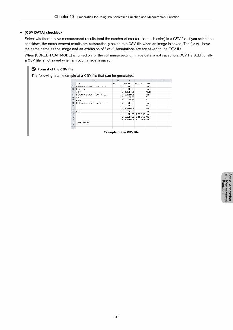
Chapter 10 Preparation for Using the Annotation Function and Measurement Function
97
Scale, A
nnotation,
and Me
asurement
Functions
[CSV DATA] checkbox
Select whether to save measurement results (and the number of markers for each color) in a CSV file. If you select the
checkbox, the measurement results are automatically saved to a CSV file when an image is saved. The file will have
the same name as the image and an extension of ".csv". Annotations are not saved to the CSV file.
When [SCREEN CAP MODE] is turned on for the still image setting, image data is not saved to a CSV file. Additionally,
a CSV file is not saved when a motion image is saved.
Format of the CSV file
The following is an example of a CSV file that can be generated.
Example of the CSV file
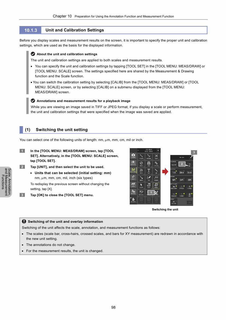
Chapter 10 Preparation for Using the Annotation Function and Measurement Function
98
Scale, A
nnotation,
and Me
asurement
Functions
10.1.3 Unit and Calibration Settings
Before you display scales and measurement results on the screen, it is important to specify the proper unit and calibration
settings, which are used as the basis for the displayed information.
About the unit and calibration settings
The unit and calibration settings are applied to both scales and measurement results.
You can specify the unit and calibration settings by tapping [TOOL SET] in the [TOOL MENU: MEAS/DRAW] or
[TOOL MENU: SCALE] screen. The settings specified here are shared by the Measurement & Drawing
function and the Scale function.
You can switch the calibration setting by selecting [CALIB] from the [TOOL MENU: MEAS/DRAW] or [TOOL
MENU: SCALE] screen, or by selecting [CALIB] on a submenu displayed from the [TOOL MENU:
MEAS/DRAW] screen.
Annotations and measurement results for a playback image
While you are viewing an image saved in TIFF or JPEG format, if you display a scale or perform measurement,
the unit and calibration settings that were specified when the image was saved are applied.
(1) Switching the unit setting
You can select one of the following units of length: nm, m, mm, cm, mil or inch.
1 In the [TOOL MENU: MEAS/DRAW] screen, tap [TOOL
SET]. Alternatively, in the [TOOL MENU: SCALE] screen,
tap [TOOL SET].
2 Tap [UNIT], and then select the unit to be used.
Units that can be selected (initial setting: mm)
nm, m, mm, cm, mil, inch (six types)
To redisplay the previous screen without changing the
setting, tap [X].
3 Tap [OK] to close the [TOOL SET] menu.
Switching the unit
Switching of the unit and overlay information
Switching of the unit affects the scale, annotation, and measurement functions as follows:
The scales (scale bar, cross-hairs, crossed scales, and bars for XY measurement) are redrawn in accordance with
the new unit setting.
The annotations do not change.
For the measurement results, the unit is changed.
2
1
3
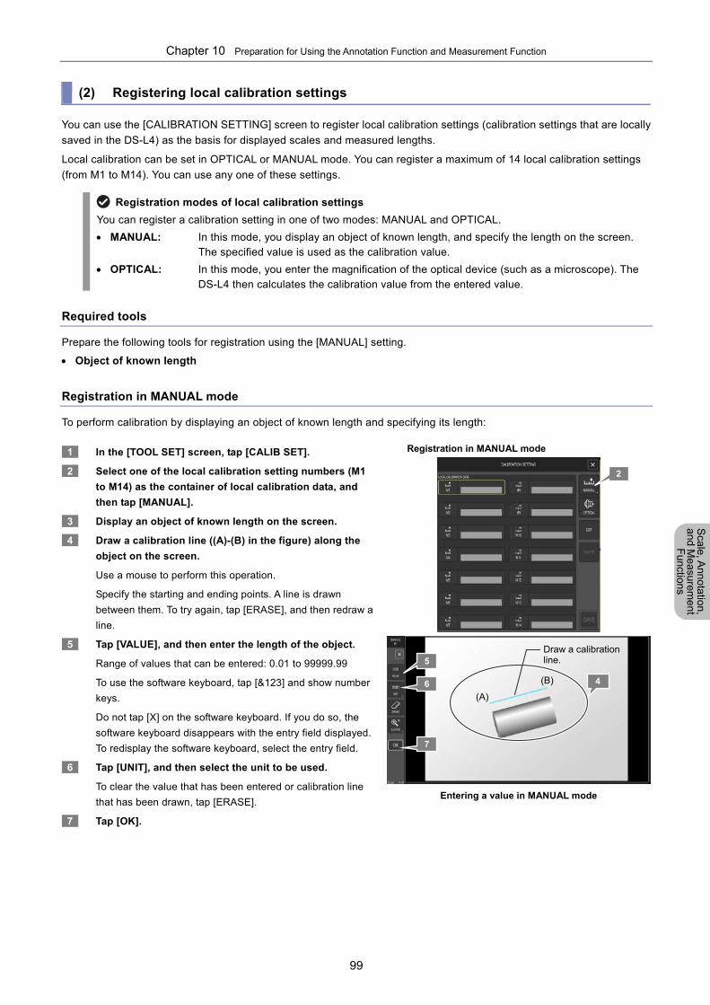
Chapter 10 Preparation for Using the Annotation Function and Measurement Function
99
Scale, A
nnotation,
and Me
asurement
Functions
(2) Registering local calibration settings
You can use the [CALIBRATION SETTING] screen to register local calibration settings (calibration settings that are locally
saved in the DS-L4) as the basis for displayed scales and measured lengths.
Local calibration can be set in OPTICAL or MANUAL mode. You can register a maximum of 14 local calibration settings
(from M1 to M14). You can use any one of these settings.
Registration modes of local calibration settings
You can register a calibration setting in one of two modes: MANUAL and OPTICAL.
MANUAL: In this mode, you display an object of known length, and specify the length on the screen. The specified value is used as the calibration value.
OPTICAL: In this mode, you enter the magnification of the optical device (such as a microscope). The DS-L4 then calculates the calibration value from the entered value.
Required tools
Prepare the following tools for registration using the [MANUAL] setting.
Object of known length
Registration in MANUAL mode
To perform calibration by displaying an object of known length and specifying its length:
1 In the [TOOL SET] screen, tap [CALIB SET].
2 Select one of the local calibration setting numbers (M1
to M14) as the container of local calibration data, and
then tap [MANUAL].
3 Display an object of known length on the screen.
4 Draw a calibration line ((A)-(B) in the figure) along the
object on the screen.
Use a mouse to perform this operation.
Specify the starting and ending points. A line is drawn
between them. To try again, tap [ERASE], and then redraw a
line.
5 Tap [VALUE], and then enter the length of the object.
Range of values that can be entered: 0.01 to 99999.99
To use the software keyboard, tap [&123] and show number
keys.
Do not tap [X] on the software keyboard. If you do so, the
software keyboard disappears with the entry field displayed.
To redisplay the software keyboard, select the entry field.
6 Tap [UNIT], and then select the unit to be used.
To clear the value that has been entered or calibration line
that has been drawn, tap [ERASE].
7 Tap [OK].
Registration in MANUAL mode
Entering a value in MANUAL mode
(A)
(B) 4
Draw a calibration line. 5
6
7
2
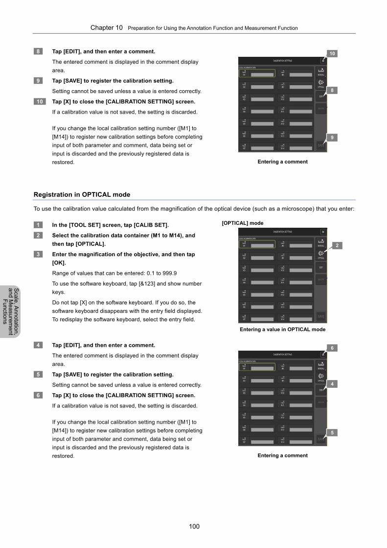
Chapter 10 Preparation for Using the Annotation Function and Measurement Function
100
Scale, A
nnotation,
and Me
asurement
Functions
8 Tap [EDIT], and then enter a comment.
The entered comment is displayed in the comment display
area.
9 Tap [SAVE] to register the calibration setting.
Setting cannot be saved unless a value is entered correctly.
10 Tap [X] to close the [CALIBRATION SETTING] screen.
If a calibration value is not saved, the setting is discarded.
If you change the local calibration setting number ([M1] to
[M14]) to register new calibration settings before completing
input of both parameter and comment, data being set or
input is discarded and the previously registered data is
restored.
Entering a comment
Registration in OPTICAL mode
To use the calibration value calculated from the magnification of the optical device (such as a microscope) that you enter:
1 In the [TOOL SET] screen, tap [CALIB SET].
2 Select the calibration data container (M1 to M14), and
then tap [OPTICAL].
3 Enter the magnification of the objective, and then tap
[OK].
Range of values that can be entered: 0.1 to 999.9
To use the software keyboard, tap [&123] and show number
keys.
Do not tap [X] on the software keyboard. If you do so, the
software keyboard disappears with the entry field displayed.
To redisplay the software keyboard, select the entry field.
[OPTICAL] mode
Entering a value in OPTICAL mode
4 Tap [EDIT], and then enter a comment.
The entered comment is displayed in the comment display
area.
5 Tap [SAVE] to register the calibration setting.
Setting cannot be saved unless a value is entered correctly.
6 Tap [X] to close the [CALIBRATION SETTING] screen.
If a calibration value is not saved, the setting is discarded.
If you change the local calibration setting number ([M1] to
[M14]) to register new calibration settings before completing
input of both parameter and comment, data being set or
input is discarded and the previously registered data is
restored.
Entering a comment
8
2
4
5
6
9
10
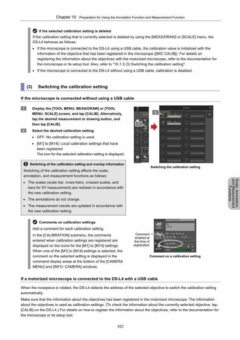
Chapter 10 Preparation for Using the Annotation Function and Measurement Function
101
Scale, A
nnotation,
and Me
asurement
Functions
If the selected calibration setting is deleted
If the calibration setting that is currently selected is deleted by using the [MEAS/DRAW] or [SCALE] menu, the DS-L4 behaves as follows.
If the microscope is connected to the DS-L4 using a USB cable, the calibration value is initialized with the
information of the objective that has been registered in the microscope ([MIC CALIB]). For details on
registering the information about the objectives with the motorized microscope, refer to the documentation for
the microscope or its setup tool. Also, refer to "10.1.3 (3) Switching the calibration setting".
If the microscope is connected to the DS-L4 without using a USB cable, calibration is disabled.
(3) Switching the calibration setting
If the microscope is connected without using a USB cable
1 Display the [TOOL MENU: MEAS/DRAW] or [TOOL
MENU: SCALE] screen, and tap [CALIB]. Alternatively,
tap the desired measurement or drawing button, and
then tap [CALIB].
2 Select the desired calibration setting.
OFF: No calibration setting is used.
[M1] to [M14]: Local calibration settings that have
been registered
The icon for the selected calibration setting is displayed.
Switching of the calibration setting and overlay information
Switching of the calibration setting affects the scale,
annotation, and measurement functions as follows:
The scales (scale bar, cross-hairs, crossed scales, and
bars for XY measurement) are redrawn in accordance with
the new calibration setting.
The annotations do not change.
The measurement results are updated in accordance with
the new calibration setting.
Switching the calibration setting
Comments on calibration settings
Add a comment for each calibration setting.
In the [CALIBRATION] submenu, the comments
entered when calibration settings are registered are
displayed on the icons for the [M1] to [M14] settings.
When one of the [M1] to [M14] settings is selected, the
comment on the selected setting is displayed in the
command display areas at the bottom of the [CAMERA
MENU] and [INFO: CAMERA] windows.
Comment on a calibration setting
If a motorized microscope is connected to the DS-L4 with a USB cable
When the nosepiece is rotated, the DS-L4 detects the address of the selected objective to switch the calibration setting
automatically.
Make sure that the information about the objectives has been registered in the motorized microscope. The information
about the objectives is used as calibration settings. (To check the information about the currently selected objective, tap
[CALIB] on the DS-L4.) For details on how to register the information about the objectives, refer to the documentation for
the microscope or its setup tool.
1
Commententered atthe time of
registration
2
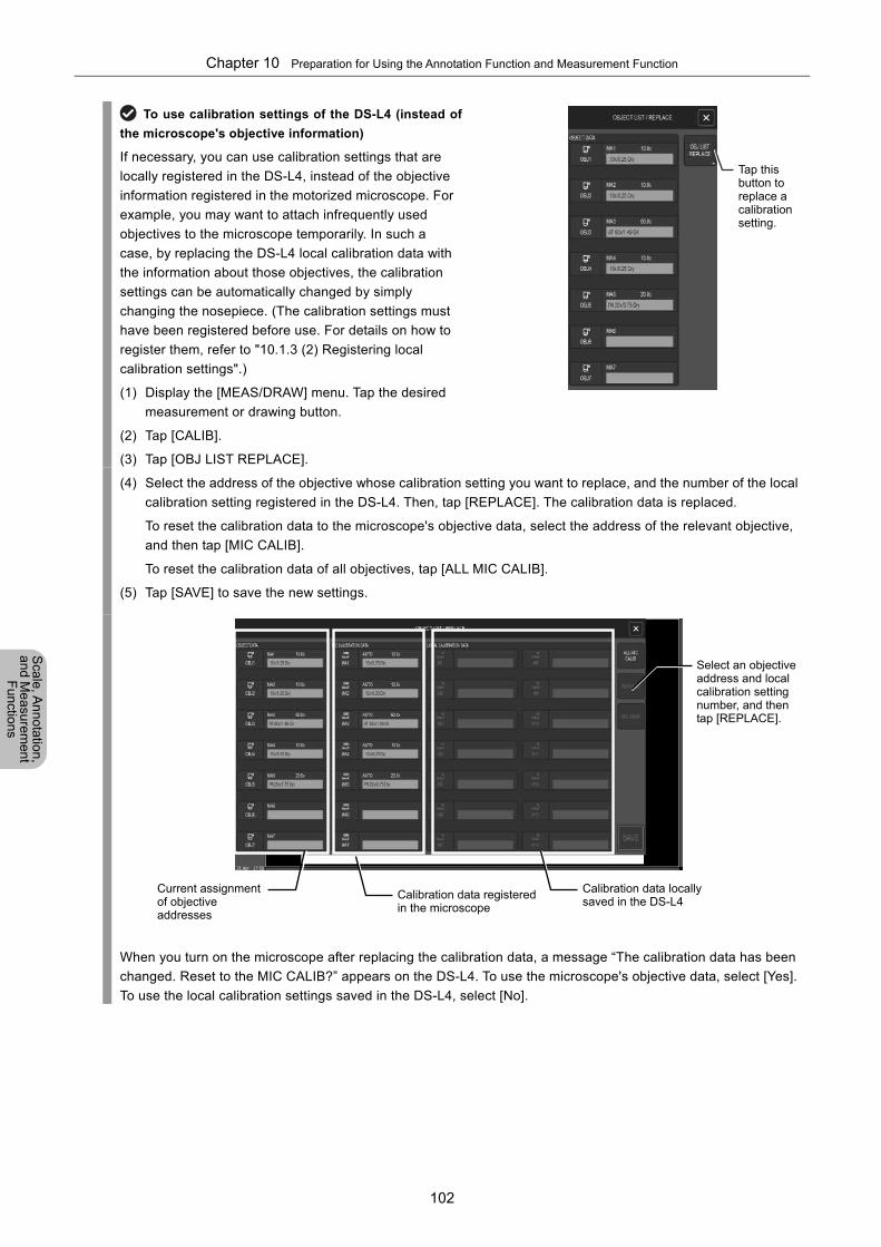
Chapter 10 Preparation for Using the Annotation Function and Measurement Function
102
Scale, A
nnotation,
and Me
asurement
Functions
To use calibration settings of the DS-L4 (instead of
the microscope's objective information)
If necessary, you can use calibration settings that are
locally registered in the DS-L4, instead of the objective
information registered in the motorized microscope. For
example, you may want to attach infrequently used
objectives to the microscope temporarily. In such a
case, by replacing the DS-L4 local calibration data with
the information about those objectives, the calibration
settings can be automatically changed by simply
changing the nosepiece. (The calibration settings must
have been registered before use. For details on how to
register them, refer to "10.1.3 (2) Registering local
calibration settings".)
(1) Display the [MEAS/DRAW] menu. Tap the desired
measurement or drawing button.
(2) Tap [CALIB].
(3) Tap [OBJ LIST REPLACE].
(4) Select the address of the objective whose calibration setting you want to replace, and the number of the local
calibration setting registered in the DS-L4. Then, tap [REPLACE]. The calibration data is replaced.
To reset the calibration data to the microscope's objective data, select the address of the relevant objective,
and then tap [MIC CALIB].
To reset the calibration data of all objectives, tap [ALL MIC CALIB].
(5) Tap [SAVE] to save the new settings.
When you turn on the microscope after replacing the calibration data, a message “The calibration data has been
changed. Reset to the MIC CALIB?” appears on the DS-L4. To use the microscope's objective data, select [Yes].
To use the local calibration settings saved in the DS-L4, select [No].
Calibration data locally saved in the DS-L4
Calibration data registered in the microscope
Current assignment of objective addresses
Select an objective address and local calibration setting number, and then tap [REPLACE].
Tap this button to replace a calibration setting.
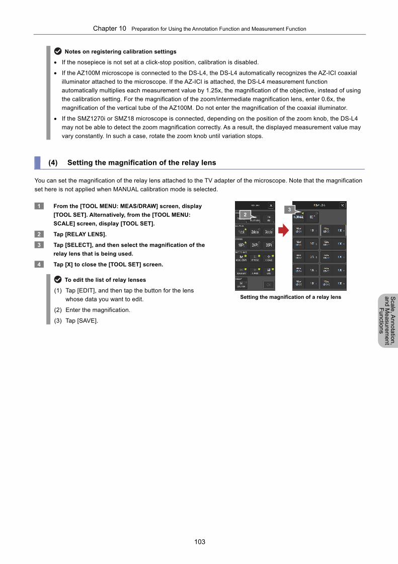
Chapter 10 Preparation for Using the Annotation Function and Measurement Function
103
Scale, A
nnotation,
and Me
asurement
Functions
Notes on registering calibration settings
If the nosepiece is not set at a click-stop position, calibration is disabled.
If the AZ100M microscope is connected to the DS-L4, the DS-L4 automatically recognizes the AZ-ICI coaxial
illuminator attached to the microscope. If the AZ-ICI is attached, the DS-L4 measurement function
automatically multiplies each measurement value by 1.25x, the magnification of the objective, instead of using
the calibration setting. For the magnification of the zoom/intermediate magnification lens, enter 0.6x, the
magnification of the vertical tube of the AZ100M. Do not enter the magnification of the coaxial illuminator.
If the SMZ1270i or SMZ18 microscope is connected, depending on the position of the zoom knob, the DS-L4
may not be able to detect the zoom magnification correctly. As a result, the displayed measurement value may
vary constantly. In such a case, rotate the zoom knob until variation stops.
(4) Setting the magnification of the relay lens
You can set the magnification of the relay lens attached to the TV adapter of the microscope. Note that the magnification
set here is not applied when MANUAL calibration mode is selected.
1 From the [TOOL MENU: MEAS/DRAW] screen, display
[TOOL SET]. Alternatively, from the [TOOL MENU:
SCALE] screen, display [TOOL SET].
2 Tap [RELAY LENS].
3 Tap [SELECT], and then select the magnification of the
relay lens that is being used.
4 Tap [X] to close the [TOOL SET] screen.
To edit the list of relay lenses
(1) Tap [EDIT], and then tap the button for the lens
whose data you want to edit.
(2) Enter the magnification.
(3) Tap [SAVE].
Setting the magnification of a relay lens
2 3
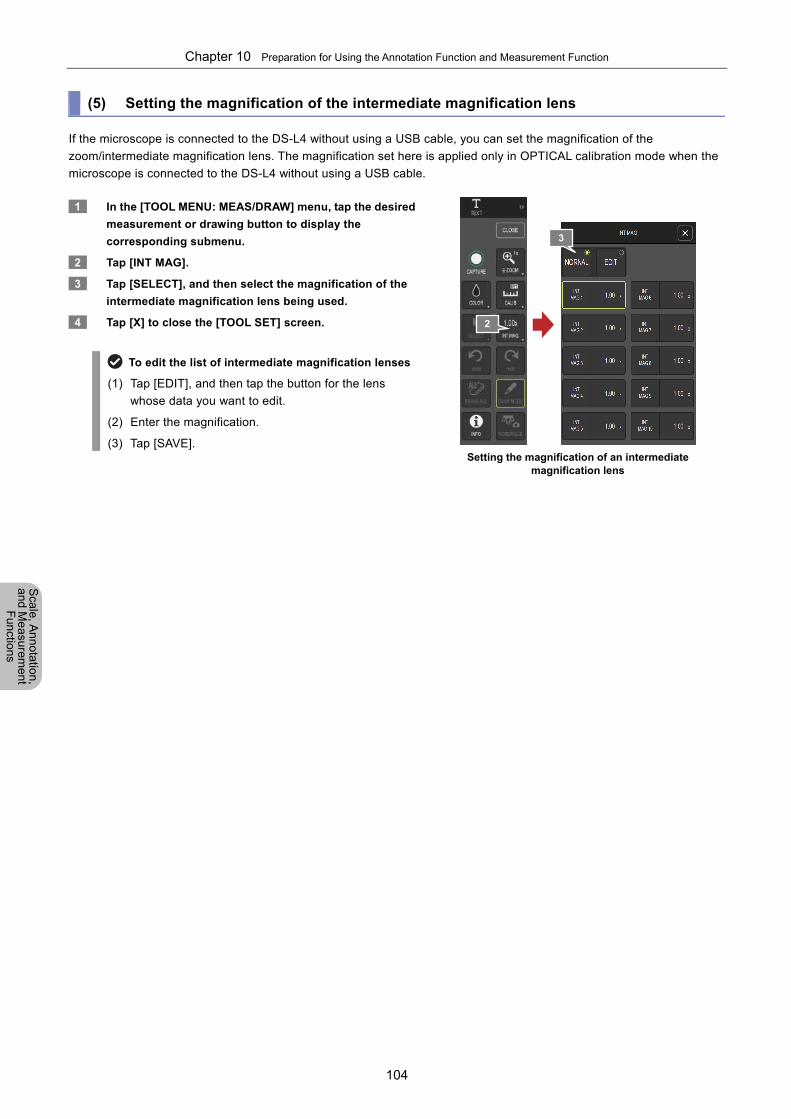
Chapter 10 Preparation for Using the Annotation Function and Measurement Function
104
Scale, A
nnotation,
and Me
asurement
Functions
(5) Setting the magnification of the intermediate magnification lens
If the microscope is connected to the DS-L4 without using a USB cable, you can set the magnification of the
zoom/intermediate magnification lens. The magnification set here is applied only in OPTICAL calibration mode when the
microscope is connected to the DS-L4 without using a USB cable.
1 In the [TOOL MENU: MEAS/DRAW] menu, tap the desired
measurement or drawing button to display the
corresponding submenu.
2 Tap [INT MAG].
3 Tap [SELECT], and then select the magnification of the
intermediate magnification lens being used.
4 Tap [X] to close the [TOOL SET] screen.
To edit the list of intermediate magnification lenses
(1) Tap [EDIT], and then tap the button for the lens
whose data you want to edit.
(2) Enter the magnification.
(3) Tap [SAVE].
Setting the magnification of an intermediate
magnification lens
2
3
Chapter 10 Preparation for Using the Annotation Function and Measurement Function
105
Scale, A
nnotation,
and Me
asurement
Functions
10.1.4 Overlay
Annotations and measurement results are drawn on a layer called an "overlay".
(1) Overview of the overlay
You can think of the overlay as a transparent sheet covered over a captured image.
Annotations (text, straight lines, arrows, free-hand lines, and markers) and measurement results are rendered on the
overlay. You can hide them temporarily or redisplay them by hiding or showing the overlay.
The overlay allows you to add annotations and perform measurement without modifying an original image.
You can save the items drawn on the overlay to an image by re-capturing the image.
Overlay and scales (scale bar, crossed scales, cross-hairs, grid, and bars for XY measurement)
The results of the functions executed from the [TOOL MENU: MEAS/DRAW] screen are drawn on the overlay.
However, the results of the functions executed from the [TOOL MENU: SCALE] screen are not drawn on the
overlay. You can show or hide each scale item individually.
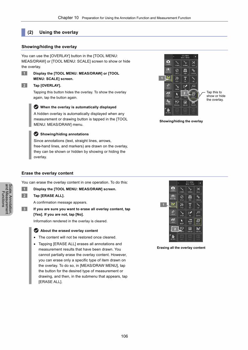
Chapter 10 Preparation for Using the Annotation Function and Measurement Function
106
Scale, A
nnotation,
and Me
asurement
Functions
(2) Using the overlay
Showing/hiding the overlay
You can use the [OVERLAY] button in the [TOOL MENU:
MEAS/DRAW] or [TOOL MENU: SCALE] screen to show or hide
the overlay.
1 Display the [TOOL MENU: MEAS/DRAW] or [TOOL
MENU: SCALE] screen.
2 Tap [OVERLAY].
Tapping this button hides the overlay. To show the overlay
again, tap the button again.
When the overlay is automatically displayed
A hidden overlay is automatically displayed when any
measurement or drawing button is tapped in the [TOOL
MENU: MEAS/DRAW] menu.
Showing/hiding annotations
Since annotations (text, straight lines, arrows,
free-hand lines, and markers) are drawn on the overlay,
they can be shown or hidden by showing or hiding the
overlay.
Showing/hiding the overlay
Erase the overlay content
You can erase the overlay content in one operation. To do this:
1 Display the [TOOL MENU: MEAS/DRAW] screen.
2 Tap [ERASE ALL].
A confirmation message appears.
3 If you are sure you want to erase all overlay content, tap
[Yes]. If you are not, tap [No].
Information rendered in the overlay is cleared.
About the erased overlay content
The content will not be restored once cleared.
Tapping [ERASE ALL] erases all annotations and
measurement results that have been drawn. You
cannot partially erase the overlay content. However,
you can erase only a specific type of item drawn on
the overlay. To do so, in [MEAS/DRAW MENU], tap
the button for the desired type of measurement or
drawing, and then, in the submenu that appears, tap
[ERASE ALL].
Erasing all the overlay content
2 Tap this to show or hide the overlay.
1
2
1
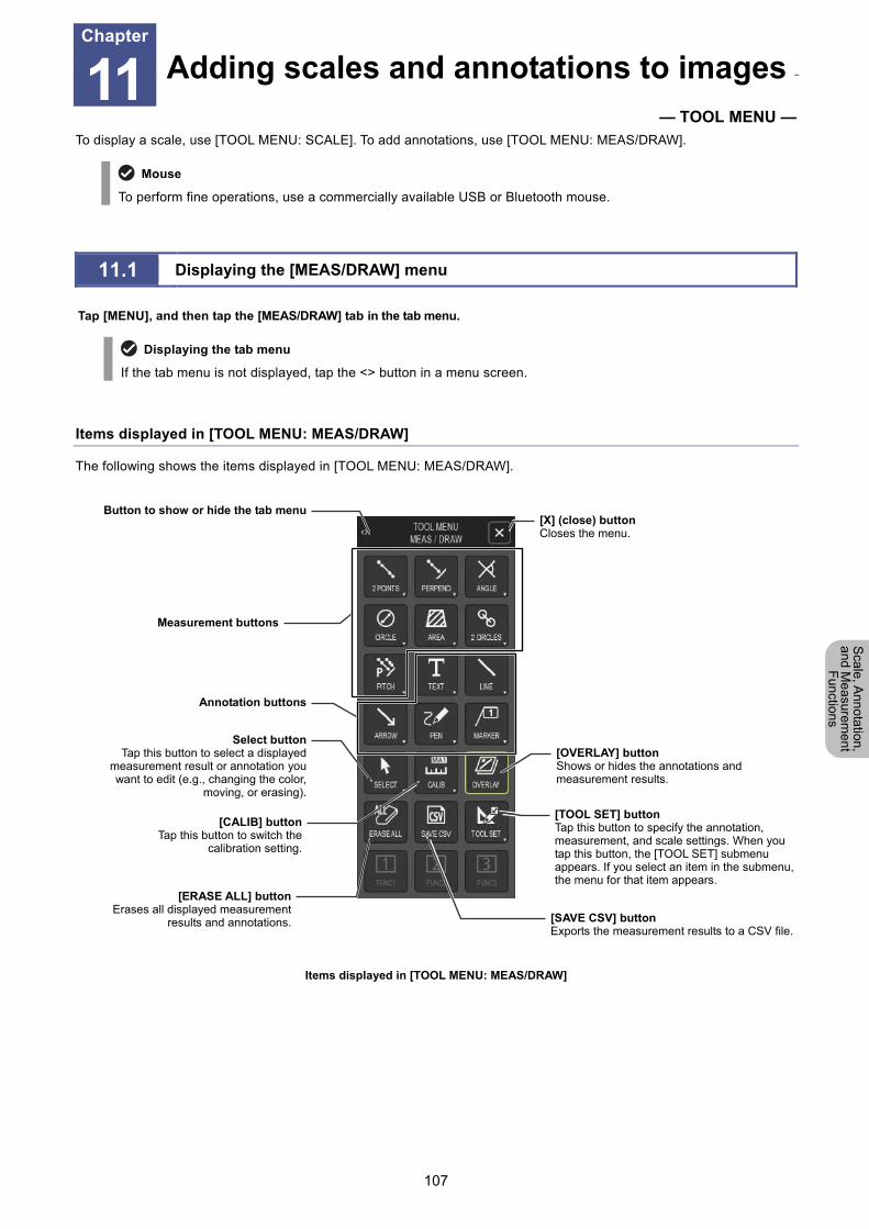
Chapter 11 Adding Lines and Annotations to an Image
107
Scale, A
nnotation,
and Me
asurement
Functions
11 Adding scales and annotations to images
— TOOL MENU — To display a scale, use [TOOL MENU: SCALE]. To add annotations, use [TOOL MENU: MEAS/DRAW].
Mouse
To perform fine operations, use a commercially available USB or Bluetooth mouse.
11.1 Displaying the [MEAS/DRAW] menu
Tap [MENU], and then tap the [MEAS/DRAW] tab in the tab menu.
Displaying the tab menu
If the tab menu is not displayed, tap the <> button in a menu screen.
Items displayed in [TOOL MENU: MEAS/DRAW]
The following shows the items displayed in [TOOL MENU: MEAS/DRAW].
Items displayed in [TOOL MENU: MEAS/DRAW]
Adding scales and annotations to imagesChapter
11
Button to show or hide the tab menu
Measurement buttons
Annotation buttons
Select buttonTap this button to select a displayed
measurement result or annotation youwant to edit (e.g., changing the color,
moving, or erasing).
[ERASE ALL] buttonErases all displayed measurement
results and annotations.
[CALIB] buttonTap this button to switch the
calibration setting.
[OVERLAY] buttonShows or hides the annotations and measurement results.
[SAVE CSV] buttonExports the measurement results to a CSV file.
[TOOL SET] buttonTap this button to specify the annotation, measurement, and scale settings. When you tap this button, the [TOOL SET] submenu appears. If you select an item in the submenu, the menu for that item appears.
[X] (close) buttonCloses the menu.
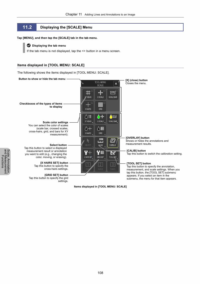
Chapter 11 Adding Lines and Annotations to an Image
108
Scale, A
nnotation,
and Me
asurement
Functions
11.2 Displaying the [SCALE] Menu
Tap [MENU], and then tap the [SCALE] tab in the tab menu.
Displaying the tab menu
If the tab menu is not displayed, tap the <> button in a menu screen.
Items displayed in [TOOL MENU: SCALE]
The following shows the items displayed in [TOOL MENU: SCALE].
Items displayed in [TOOL MENU: SCALE]
Button to show or hide the tab menu
Checkboxes of the types of itemsto display
Scale color settingsYou can select the color of scales
(scale bar, crossed scales,cross-hairs, grid, and bars for XY
measurement).
Select buttonTap this button to select a displayed
measurement result or annotationyou want to edit (e.g., changing the
color, moving, or erasing).
[X HAIRS SET] buttonTap this button to specify the
cross-hairs settings.
[CALIB] buttonTap this button to switch the calibration setting.
[OVERLAY] buttonShows or hides the annotations and measurement results.
[TOOL SET] buttonTap this button to specify the annotation, measurement, and scale settings. When you tap this button, the [TOOL SET] submenu appears. If you select an item in the submenu, the menu for that item appears.
[GRID SET] buttonTap this button to specify the grid
settings.
[X] (close) buttonCloses the menu.
Chapter 11 Adding Lines and Annotations to an Image
109
Scale, A
nnotation,
and Me
asurement
Functions
11.3 Changing the Settings of the Scale and Measurement Functions
You can specify the settings of the scale and measurement functions by tapping [TOOL SET] in the [TOOL MENU:
MEAS/DRAW] or [TOOL MENU: SCALE] screen.
1 Display the [TOOL MENU: MEAS/DRAW] or [TOOL
MENU: SCALE] screen.
2 Tap [TOOL SET].
The [TOOL SET] submenu appears. For details about the
settings that can be specified in each menu, refer to the
following pages.
Chapter 11 Adding Lines and Annotations to an Image
110
Scale, A
nnotation,
and Me
asurement
Functions
11.4 Using Scales
You can measure the dimensions of an object by displaying crossed scales, a scale bar, cross-hairs (with concentric
circles), or a grid on the screen. You can also display a pair of bars in the X and Y directions.
When adding scales to the live image
When you add a scale to a live image, depending on the status of the subject, you may fail to position the scale at the appropriate location. In such a case, tap [FREEZE], capture a still image, and then display the scale.
Displaying scales on a replayed image
For the scales displayed over an image saved in TIFF or JPEG format, the calibration setting specified when
the image was saved is applied.
You cannot display scales on a motion image.
Displayed measurement values
You can change the thickness of measurement lines and the font size of dimension values by using the [TOOL
SET] screen.
To change the scale color, tap the desired scale color setting button in the [TOOL MENU: SCALE] screen. You
can also change the scale color by tapping [SELECT] to select the target scale.
Whether to show or hide the scale is retained for each type of scale even when the power is turned off.
Modification of scales and undo/redo operations
You can change the position and color of a scale by tapping [SELECT], and then selecting the scale. You can also
undo or redo the change before closing the selection menu. To perform operations on a scale, use [TOOL MENU: SCALE]. You can perform the following operations.
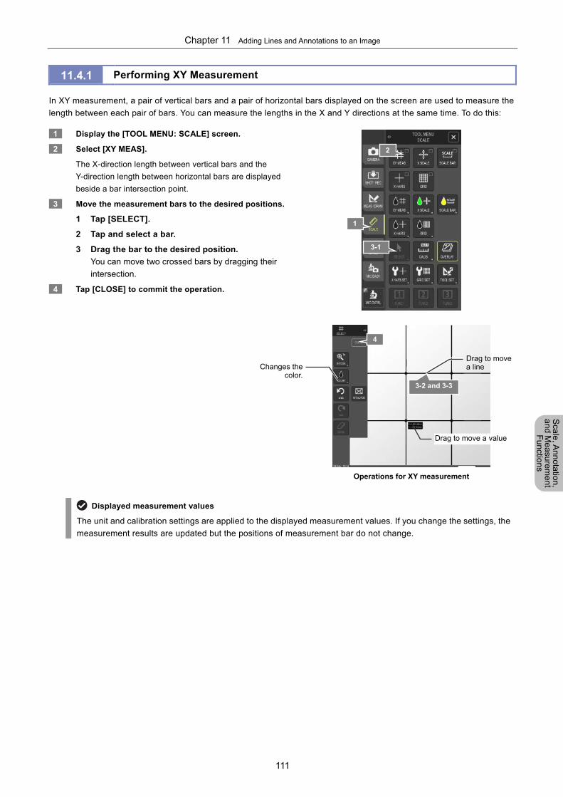
Chapter 11 Adding Lines and Annotations to an Image
111
Scale, A
nnotation,
and Me
asurement
Functions
11.4.1 Performing XY Measurement
In XY measurement, a pair of vertical bars and a pair of horizontal bars displayed on the screen are used to measure the
length between each pair of bars. You can measure the lengths in the X and Y directions at the same time. To do this:
1 Display the [TOOL MENU: SCALE] screen.
2 Select [XY MEAS].
The X-direction length between vertical bars and the
Y-direction length between horizontal bars are displayed
beside a bar intersection point.
3 Move the measurement bars to the desired positions.
1 Tap [SELECT].
2 Tap and select a bar.
3 Drag the bar to the desired position.
You can move two crossed bars by dragging their
intersection.
4 Tap [CLOSE] to commit the operation.
Operations for XY measurement
Displayed measurement values
The unit and calibration settings are applied to the displayed measurement values. If you change the settings, the
measurement results are updated but the positions of measurement bar do not change.
Changes thecolor.
Drag to move a line
Drag to move a value
2
1
3-1
4
3-2 and 3-3
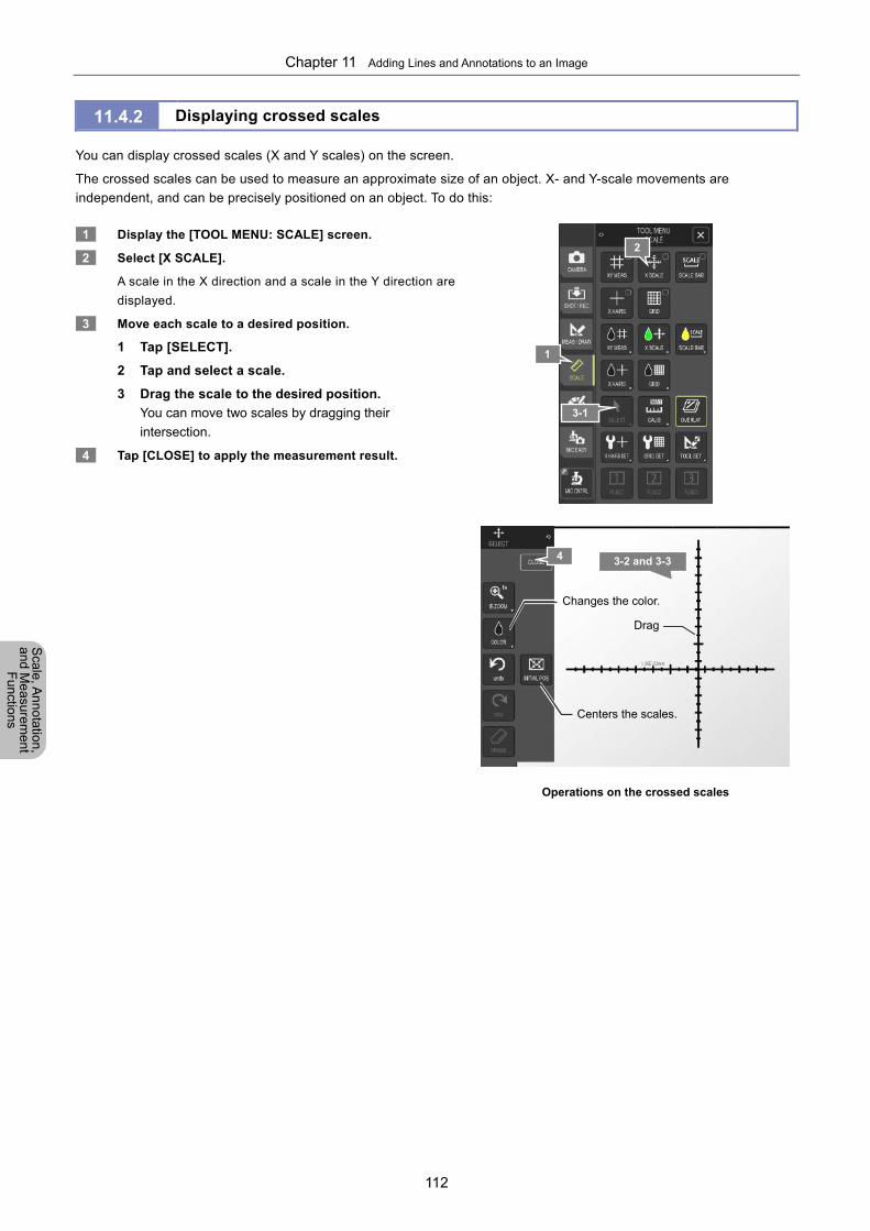
Chapter 11 Adding Lines and Annotations to an Image
112
Scale, A
nnotation,
and Me
asurement
Functions
11.4.2 Displaying crossed scales
You can display crossed scales (X and Y scales) on the screen.
The crossed scales can be used to measure an approximate size of an object. X- and Y-scale movements are
independent, and can be precisely positioned on an object. To do this:
1 Display the [TOOL MENU: SCALE] screen.
2 Select [X SCALE].
A scale in the X direction and a scale in the Y direction are
displayed.
3 Move each scale to a desired position.
1 Tap [SELECT].
2 Tap and select a scale.
3 Drag the scale to the desired position.
You can move two scales by dragging their
intersection.
4 Tap [CLOSE] to apply the measurement result.
Operations on the crossed scales
1
2
3-2 and 3-3
3-1
Centers the scales.
Changes the color.
Drag
4

Chapter 11 Adding Lines and Annotations to an Image
113
Scale, A
nnotation,
and Me
asurement
Functions
11.4.3 Displaying the Scale Bar
The following describes how to display the scale bar. With the scale bar, you can obtain an approximate size of a subject.
To do this:
1 Display the [TOOL MENU: SCALE] screen.
2 Select [SCALE BAR].
3 Move and resize the scale bar as desired.
1 Tap [SELECT].
2 Tap and select the scale bar.
3 Use the mouse to drag an end point of the scale
bar to change the length of the scale bar.
4 Use the mouse to drag the scale bar to the
desired position.
4 Tap [CLOSE] to commit the operation.
[SCALE] Menu
Scale bar operations
Display of the scale bar
The length of the scale bar is adjusted to provide one significant figure. The minimum length is 1/8 of the width
of the image display area.
The scale bar cannot be rotated at a desired angle.
Drag to resize
Changes the direction Drag to move
1
2
3-2, 3-3, and 3-4
3-1
4
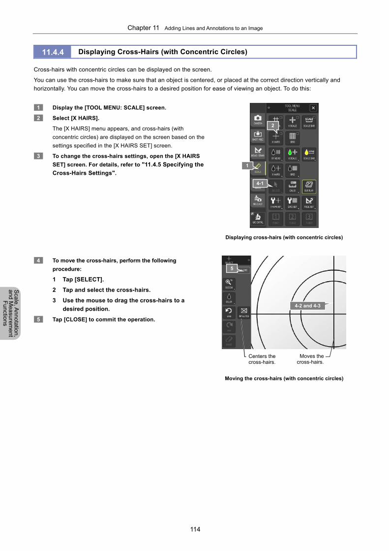
Chapter 11 Adding Lines and Annotations to an Image
114
Scale, A
nnotation,
and Me
asurement
Functions
11.4.4 Displaying Cross-Hairs (with Concentric Circles)
Cross-hairs with concentric circles can be displayed on the screen.
You can use the cross-hairs to make sure that an object is centered, or placed at the correct direction vertically and
horizontally. You can move the cross-hairs to a desired position for ease of viewing an object. To do this:
1 Display the [TOOL MENU: SCALE] screen.
2 Select [X HAIRS].
The [X HAIRS] menu appears, and cross-hairs (with
concentric circles) are displayed on the screen based on the
settings specified in the [X HAIRS SET] screen.
3 To change the cross-hairs settings, open the [X HAIRS
SET] screen. For details, refer to "11.4.5 Specifying the
Cross-Hairs Settings".
Displaying cross-hairs (with concentric circles)
4 To move the cross-hairs, perform the following
procedure:
1 Tap [SELECT].
2 Tap and select the cross-hairs.
3 Use the mouse to drag the cross-hairs to a
desired position.
5 Tap [CLOSE] to commit the operation.
Moving the cross-hairs (with concentric circles)
5
Moves thecross-hairs.
Centers the cross-hairs.
1
2
4-2 and 4-3
4-1
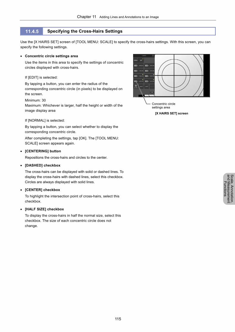
Chapter 11 Adding Lines and Annotations to an Image
115
Scale, A
nnotation,
and Me
asurement
Functions
11.4.5 Specifying the Cross-Hairs Settings
Use the [X HAIRS SET] screen of [TOOL MENU: SCALE] to specify the cross-hairs settings. With this screen, you can
specify the following settings.
Concentric circle settings area
Use the items in this area to specify the settings of concentric
circles displayed with cross-hairs.
If [EDIT] is selected:
By tapping a button, you can enter the radius of the
corresponding concentric circle (in pixels) to be displayed on
the screen.
Minimum: 30
Maximum: Whichever is larger, half the height or width of the
image display area
If [NORMAL] is selected:
By tapping a button, you can select whether to display the
corresponding concentric circle.
After completing the settings, tap [OK]. The [TOOL MENU:
SCALE] screen appears again.
[CENTERING] button
Repositions the cross-hairs and circles to the center.
[DASHED] checkbox
The cross-hairs can be displayed with solid or dashed lines. To
display the cross-hairs with dashed lines, select this checkbox.
Circles are always displayed with solid lines.
[CENTER] checkbox
To highlight the intersection point of cross-hairs, select this
checkbox.
[HALF SIZE] checkbox
To display the cross-hairs in half the normal size, select this
checkbox. The size of each concentric circle does not
change.
[X HAIRS SET] screen
Concentric circle settings area
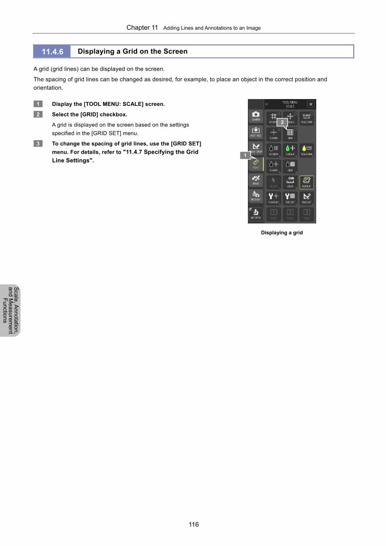
Chapter 11 Adding Lines and Annotations to an Image
116
Scale, A
nnotation,
and Me
asurement
Functions
11.4.6 Displaying a Grid on the Screen
A grid (grid lines) can be displayed on the screen.
The spacing of grid lines can be changed as desired, for example, to place an object in the correct position and
orientation.
1 Display the [TOOL MENU: SCALE] screen.
2 Select the [GRID] checkbox.
A grid is displayed on the screen based on the settings
specified in the [GRID SET] menu.
3 To change the spacing of grid lines, use the [GRID SET]
menu. For details, refer to "11.4.7 Specifying the Grid
Line Settings".
Displaying a grid
1
2
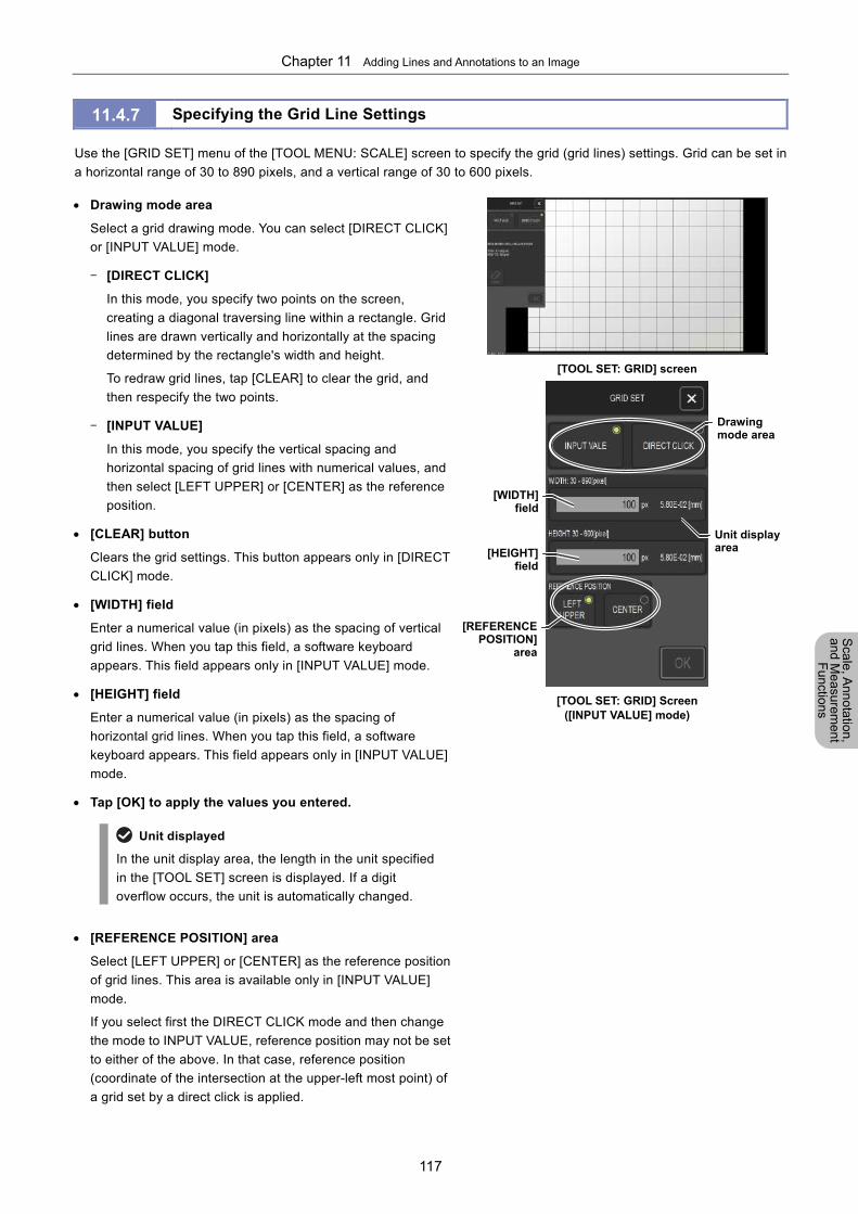
Chapter 11 Adding Lines and Annotations to an Image
117
Scale, A
nnotation,
and Me
asurement
Functions
11.4.7 Specifying the Grid Line Settings
Use the [GRID SET] menu of the [TOOL MENU: SCALE] screen to specify the grid (grid lines) settings. Grid can be set in
a horizontal range of 30 to 890 pixels, and a vertical range of 30 to 600 pixels.
Drawing mode area
Select a grid drawing mode. You can select [DIRECT CLICK]
or [INPUT VALUE] mode.
- [DIRECT CLICK]
In this mode, you specify two points on the screen,
creating a diagonal traversing line within a rectangle. Grid
lines are drawn vertically and horizontally at the spacing
determined by the rectangle's width and height.
To redraw grid lines, tap [CLEAR] to clear the grid, and
then respecify the two points.
- [INPUT VALUE]
In this mode, you specify the vertical spacing and
horizontal spacing of grid lines with numerical values, and
then select [LEFT UPPER] or [CENTER] as the reference
position.
[CLEAR] button
Clears the grid settings. This button appears only in [DIRECT
CLICK] mode.
[WIDTH] field
Enter a numerical value (in pixels) as the spacing of vertical
grid lines. When you tap this field, a software keyboard
appears. This field appears only in [INPUT VALUE] mode.
[HEIGHT] field
Enter a numerical value (in pixels) as the spacing of
horizontal grid lines. When you tap this field, a software
keyboard appears. This field appears only in [INPUT VALUE]
mode.
Tap [OK] to apply the values you entered.
Unit displayed
In the unit display area, the length in the unit specified
in the [TOOL SET] screen is displayed. If a digit
overflow occurs, the unit is automatically changed.
[REFERENCE POSITION] area
Select [LEFT UPPER] or [CENTER] as the reference position
of grid lines. This area is available only in [INPUT VALUE]
mode.
If you select first the DIRECT CLICK mode and then change
the mode to INPUT VALUE, reference position may not be set
to either of the above. In that case, reference position
(coordinate of the intersection at the upper-left most point) of
a grid set by a direct click is applied.
[TOOL SET: GRID] screen
[TOOL SET: GRID] Screen
([INPUT VALUE] mode)
[WIDTH]field
[REFERENCEPOSITION]
area
[HEIGHT]field
Drawing mode area
Unit display area
Chapter 11 Adding Lines and Annotations to an Image
118
Scale, A
nnotation,
and Me
asurement
Functions
11.5 Adding Annotations to Images
You can add lines, comments, and other annotations to images.
For live images
When adding an annotation to an object in a live image, you may fail to add it at the desired position, depending
on the status of the object. In such a case, tap [FREEZE], capture a still image, and then add the annotation to
the still image.
Display of annotations
Display of annotations is not affected by changes to the unit and calibration settings.
The line thickness and font size settings can be changed by using the [TOOL SET] screen. Note that these
settings are applied to all annotations displayed by the annotation and measurement functions.
To select the color of annotations to be added, select the desired annotation tool, and then tap [COLOR]. To
change the color of annotations that have already been drawn, select the target annotation from the [SELECT]
menu, and then tap the desired color.
You cannot selectively show or hide only annotations. You can only display or hide added information on an
overlay basis.
We recommend that you use a mouse.
To operate the annotation function, use [TOOL MENU]. You can perform the following operations.
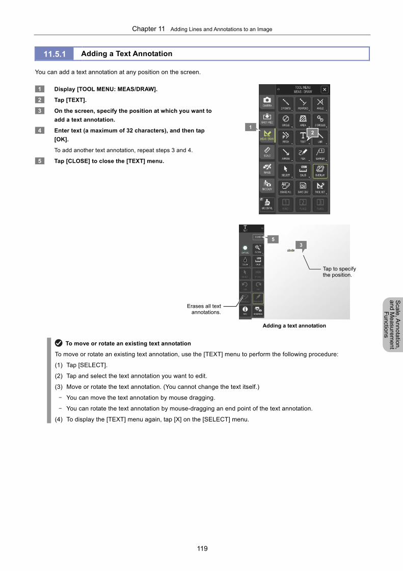
Chapter 11 Adding Lines and Annotations to an Image
119
Scale, A
nnotation,
and Me
asurement
Functions
11.5.1 Adding a Text Annotation
You can add a text annotation at any position on the screen.
1 Display [TOOL MENU: MEAS/DRAW].
2 Tap [TEXT].
3 On the screen, specify the position at which you want to
add a text annotation.
4 Enter text (a maximum of 32 characters), and then tap
[OK].
To add another text annotation, repeat steps 3 and 4.
5 Tap [CLOSE] to close the [TEXT] menu.
Adding a text annotation
To move or rotate an existing text annotation
To move or rotate an existing text annotation, use the [TEXT] menu to perform the following procedure:
(1) Tap [SELECT].
(2) Tap and select the text annotation you want to edit.
(3) Move or rotate the text annotation. (You cannot change the text itself.)
- You can move the text annotation by mouse dragging.
- You can rotate the text annotation by mouse-dragging an end point of the text annotation.
(4) To display the [TEXT] menu again, tap [X] on the [SELECT] menu.
1 2
35
Erases all textannotations.
Tap to specify the position.
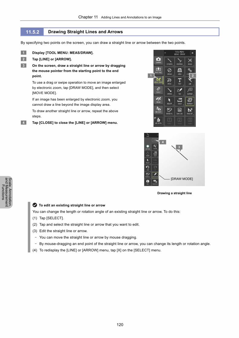
Chapter 11 Adding Lines and Annotations to an Image
120
Scale, A
nnotation,
and Me
asurement
Functions
11.5.2 Drawing Straight Lines and Arrows
By specifying two points on the screen, you can draw a straight line or arrow between the two points.
1 Display [TOOL MENU: MEAS/DRAW].
2 Tap [LINE] or [ARROW].
3 On the screen, draw a straight line or arrow by dragging
the mouse pointer from the starting point to the end
point.
To use a drag or swipe operation to move an image enlarged
by electronic zoom, tap [DRAW MODE], and then select
[MOVE MODE].
If an image has been enlarged by electronic zoom, you
cannot draw a line beyond the image display area.
To draw another straight line or arrow, repeat the above
steps.
4 Tap [CLOSE] to close the [LINE] or [ARROW] menu.
Drawing a straight line
To edit an existing straight line or arrow
You can change the length or rotation angle of an existing straight line or arrow. To do this:
(1) Tap [SELECT].
(2) Tap and select the straight line or arrow that you want to edit.
(3) Edit the straight line or arrow.
- You can move the straight line or arrow by mouse dragging.
- By mouse-dragging an end point of the straight line or arrow, you can change its length or rotation angle.
(4) To redisplay the [LINE] or [ARROW] menu, tap [X] on the [SELECT] menu.
[DRAW MODE]
1 2
3
4
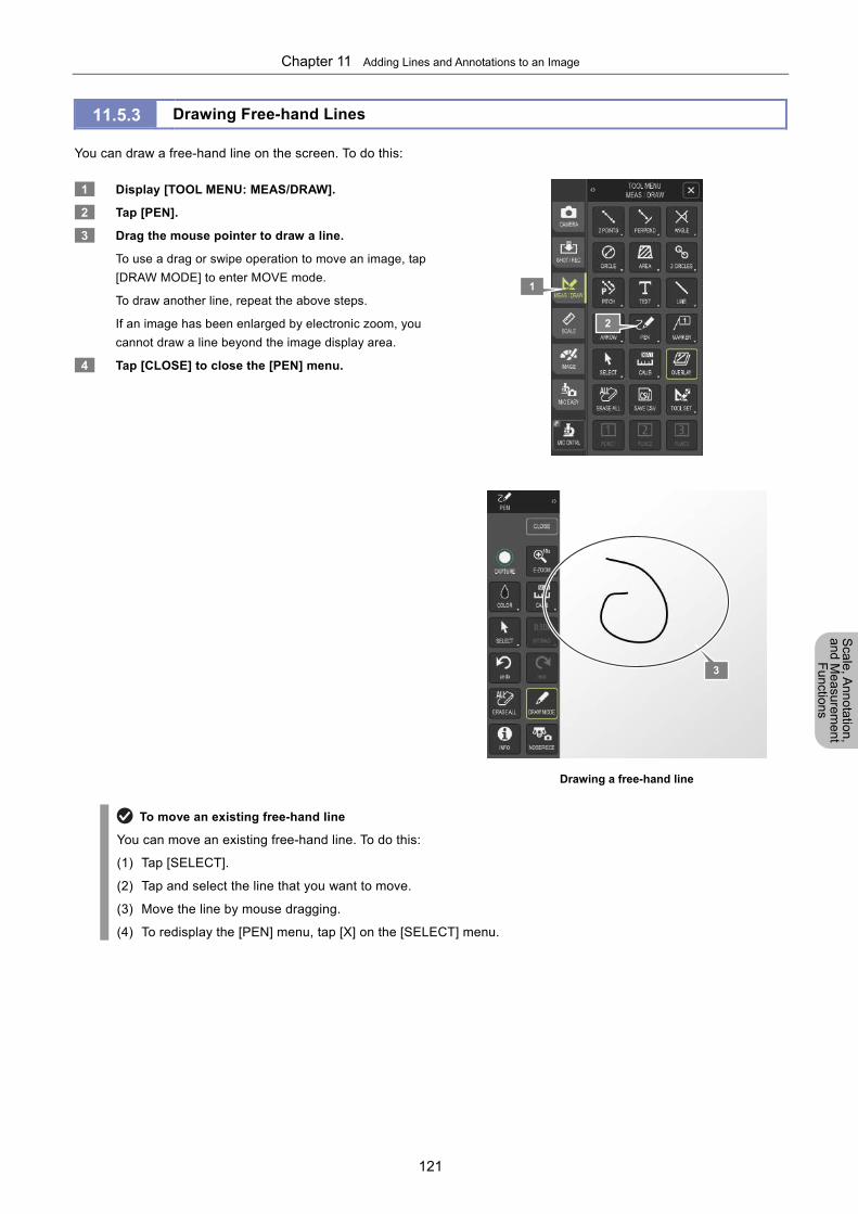
Chapter 11 Adding Lines and Annotations to an Image
121
Scale, A
nnotation,
and Me
asurement
Functions
11.5.3 Drawing Free-hand Lines
You can draw a free-hand line on the screen. To do this:
1 Display [TOOL MENU: MEAS/DRAW].
2 Tap [PEN].
3 Drag the mouse pointer to draw a line.
To use a drag or swipe operation to move an image, tap
[DRAW MODE] to enter MOVE mode.
To draw another line, repeat the above steps.
If an image has been enlarged by electronic zoom, you
cannot draw a line beyond the image display area.
4 Tap [CLOSE] to close the [PEN] menu.
Drawing a free-hand line
To move an existing free-hand line
You can move an existing free-hand line. To do this:
(1) Tap [SELECT].
(2) Tap and select the line that you want to move.
(3) Move the line by mouse dragging.
(4) To redisplay the [PEN] menu, tap [X] on the [SELECT] menu.
3
1
2
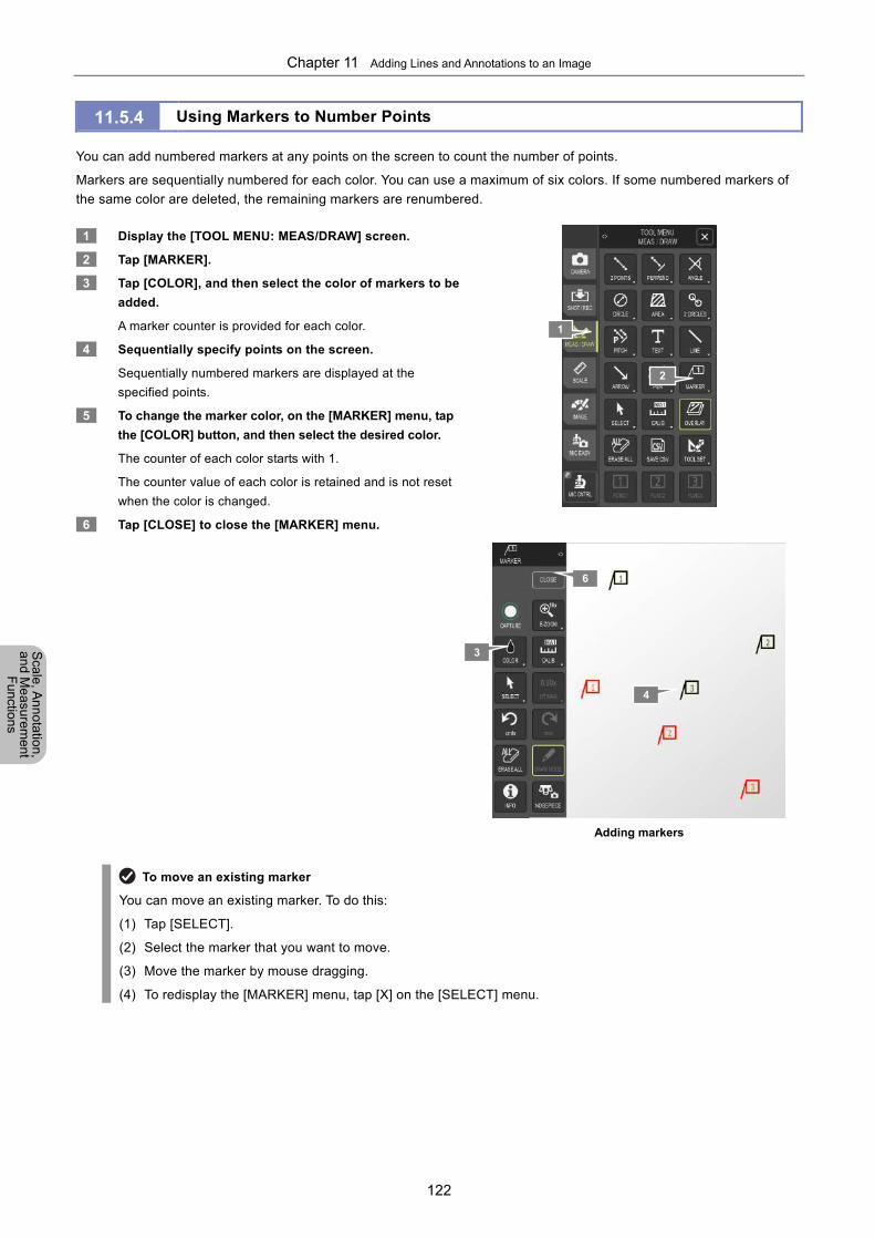
Chapter 11 Adding Lines and Annotations to an Image
122
Scale, A
nnotation,
and Me
asurement
Functions
11.5.4 Using Markers to Number Points
You can add numbered markers at any points on the screen to count the number of points.
Markers are sequentially numbered for each color. You can use a maximum of six colors. If some numbered markers of
the same color are deleted, the remaining markers are renumbered.
1 Display the [TOOL MENU: MEAS/DRAW] screen.
2 Tap [MARKER].
3 Tap [COLOR], and then select the color of markers to be
added.
A marker counter is provided for each color.
4 Sequentially specify points on the screen.
Sequentially numbered markers are displayed at the
specified points.
5 To change the marker color, on the [MARKER] menu, tap
the [COLOR] button, and then select the desired color.
The counter of each color starts with 1.
The counter value of each color is retained and is not reset
when the color is changed.
6 Tap [CLOSE] to close the [MARKER] menu.
Adding markers
To move an existing marker
You can move an existing marker. To do this:
(1) Tap [SELECT].
(2) Select the marker that you want to move.
(3) Move the marker by mouse dragging.
(4) To redisplay the [MARKER] menu, tap [X] on the [SELECT] menu.
3
1
2
4
6
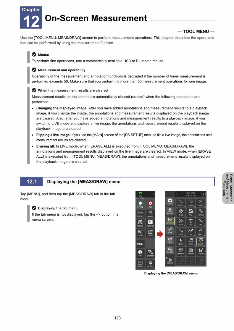
Chapter 12 On-Screen Measurement
123
Scale, A
nnotation,
and Me
asurement
Functions
12 On-Screen Measurement
— TOOL MENU — Use the [TOOL MENU: MEAS/DRAW] screen to perform measurement operations. This chapter describes the operations
that can be performed by using the measurement function.
Mouse
To perform fine operations, use a commercially available USB or Bluetooth mouse.
Measurement and operability
Operability of the measurement and annotation functions is degraded if the number of times measurement is
performed exceeds 50. Make sure that you perform no more than 50 measurement operations for one image.
When the measurement results are cleared
Measurement results on the screen are automatically cleared (erased) when the following operations are
performed:
Changing the displayed image: After you have added annotations and measurement results to a playback
image, if you change the image, the annotations and measurement results displayed on the playback image
are cleared. Also, after you have added annotations and measurement results to a playback image, if you
switch to LIVE mode and capture a live image, the annotations and measurement results displayed on the
playback image are cleared.
Flipping a live image: If you use the [MAIN] screen of the [DS SETUP] menu to flip a live image, the annotations and
measurement results are cleared.
Erasing all: In LIVE mode, when [ERASE ALL] is executed from [TOOL MENU: MEAS/DRAW], the
annotations and measurement results displayed on the live image are cleared. In VIEW mode, when [ERASE
ALL] is executed from [TOOL MENU: MEAS/DRAW], the annotations and measurement results displayed on
the playback image are cleared.
12.1 Displaying the [MEAS/DRAW] menu
Tap [MENU], and then tap the [MEAS/DRAW] tab in the tab
menu.
Displaying the tab menu
If the tab menu is not displayed, tap the <> button in a
menu screen.
Displaying the [MEAS/DRAW] menu
On-Screen Measurement Chapter
12
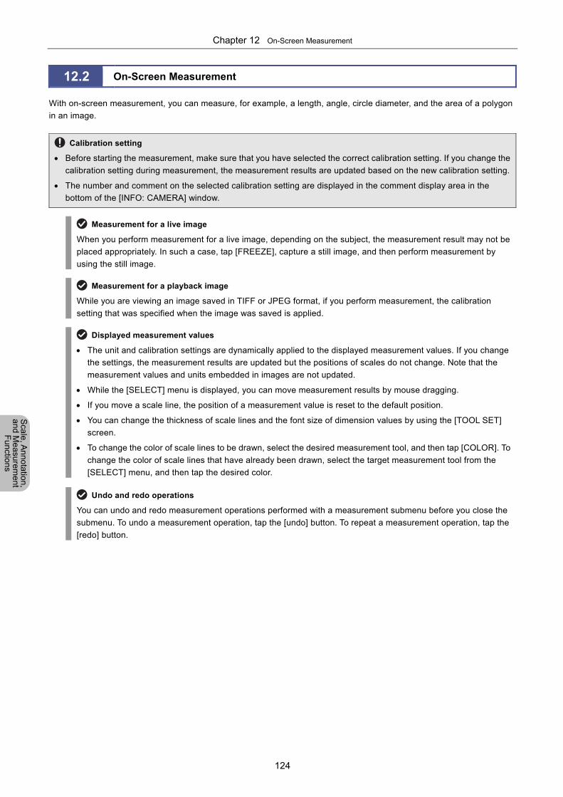
Chapter 12 On-Screen Measurement
124
Scale, A
nnotation,
and Me
asurement
Functions
12.2 On-Screen Measurement
With on-screen measurement, you can measure, for example, a length, angle, circle diameter, and the area of a polygon
in an image.
Calibration setting
Before starting the measurement, make sure that you have selected the correct calibration setting. If you change the
calibration setting during measurement, the measurement results are updated based on the new calibration setting.
The number and comment on the selected calibration setting are displayed in the comment display area in the
bottom of the [INFO: CAMERA] window.
Measurement for a live image
When you perform measurement for a live image, depending on the subject, the measurement result may not be
placed appropriately. In such a case, tap [FREEZE], capture a still image, and then perform measurement by
using the still image.
Measurement for a playback image
While you are viewing an image saved in TIFF or JPEG format, if you perform measurement, the calibration
setting that was specified when the image was saved is applied.
Displayed measurement values
The unit and calibration settings are dynamically applied to the displayed measurement values. If you change
the settings, the measurement results are updated but the positions of scales do not change. Note that the
measurement values and units embedded in images are not updated.
While the [SELECT] menu is displayed, you can move measurement results by mouse dragging.
If you move a scale line, the position of a measurement value is reset to the default position.
You can change the thickness of scale lines and the font size of dimension values by using the [TOOL SET]
screen.
To change the color of scale lines to be drawn, select the desired measurement tool, and then tap [COLOR]. To
change the color of scale lines that have already been drawn, select the target measurement tool from the
[SELECT] menu, and then tap the desired color.
Undo and redo operations
You can undo and redo measurement operations performed with a measurement submenu before you close the
submenu. To undo a measurement operation, tap the [undo] button. To repeat a measurement operation, tap the
[redo] button.
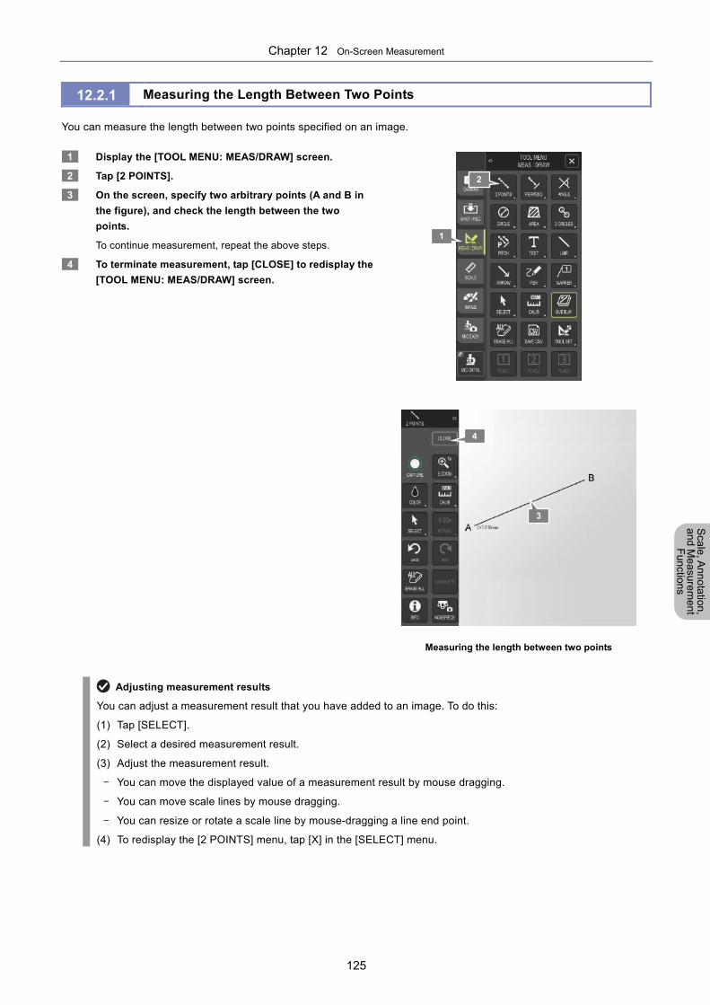
Chapter 12 On-Screen Measurement
125
Scale, A
nnotation,
and Me
asurement
Functions
12.2.1 Measuring the Length Between Two Points
You can measure the length between two points specified on an image.
1 Display the [TOOL MENU: MEAS/DRAW] screen.
2 Tap [2 POINTS].
3 On the screen, specify two arbitrary points (A and B in
the figure), and check the length between the two
points.
To continue measurement, repeat the above steps.
4 To terminate measurement, tap [CLOSE] to redisplay the
[TOOL MENU: MEAS/DRAW] screen.
Measuring the length between two points
Adjusting measurement results
You can adjust a measurement result that you have added to an image. To do this:
(1) Tap [SELECT].
(2) Select a desired measurement result.
(3) Adjust the measurement result.
- You can move the displayed value of a measurement result by mouse dragging.
- You can move scale lines by mouse dragging.
- You can resize or rotate a scale line by mouse-dragging a line end point.
(4) To redisplay the [2 POINTS] menu, tap [X] in the [SELECT] menu.
3
1
2
4
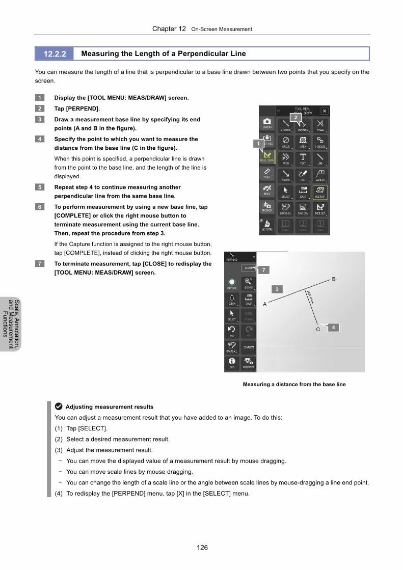
Chapter 12 On-Screen Measurement
126
Scale, A
nnotation,
and Me
asurement
Functions
12.2.2 Measuring the Length of a Perpendicular Line
You can measure the length of a line that is perpendicular to a base line drawn between two points that you specify on the
screen.
1 Display the [TOOL MENU: MEAS/DRAW] screen.
2 Tap [PERPEND].
3 Draw a measurement base line by specifying its end
points (A and B in the figure).
4 Specify the point to which you want to measure the
distance from the base line (C in the figure).
When this point is specified, a perpendicular line is drawn
from the point to the base line, and the length of the line is
displayed.
5 Repeat step 4 to continue measuring another
perpendicular line from the same base line.
6 To perform measurement by using a new base line, tap
[COMPLETE] or click the right mouse button to
terminate measurement using the current base line.
Then, repeat the procedure from step 3.
If the Capture function is assigned to the right mouse button,
tap [COMPLETE], instead of clicking the right mouse button.
7 To terminate measurement, tap [CLOSE] to redisplay the
[TOOL MENU: MEAS/DRAW] screen.
Measuring a distance from the base line
Adjusting measurement results
You can adjust a measurement result that you have added to an image. To do this:
(1) Tap [SELECT].
(2) Select a desired measurement result.
(3) Adjust the measurement result.
- You can move the displayed value of a measurement result by mouse dragging.
- You can move scale lines by mouse dragging.
- You can change the length of a scale line or the angle between scale lines by mouse-dragging a line end point.
(4) To redisplay the [PERPEND] menu, tap [X] in the [SELECT] menu.
3
4
1
2
7
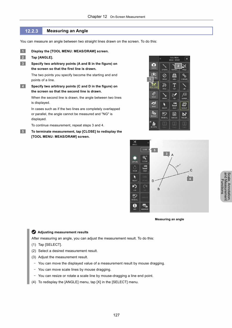
Chapter 12 On-Screen Measurement
127
Scale, A
nnotation,
and Me
asurement
Functions
12.2.3 Measuring an Angle
You can measure an angle between two straight lines drawn on the screen. To do this:
1 Display the [TOOL MENU: MEAS/DRAW] screen.
2 Tap [ANGLE].
3 Specify two arbitrary points (A and B in the figure) on
the screen so that the first line is drawn.
The two points you specify become the starting and end
points of a line.
4 Specify two arbitrary points (C and D in the figure) on
the screen so that the second line is drawn.
When the second line is drawn, the angle between two lines
is displayed.
In cases such as if the two lines are completely overlapped
or parallel, the angle cannot be measured and "NG" is
displayed.
To continue measurement, repeat steps 3 and 4.
5 To terminate measurement, tap [CLOSE] to redisplay the
[TOOL MENU: MEAS/DRAW] screen.
Measuring an angle
Adjusting measurement results
After measuring an angle, you can adjust the measurement result. To do this:
(1) Tap [SELECT].
(2) Select a desired measurement result.
(3) Adjust the measurement result.
- You can move the displayed value of a measurement result by mouse dragging.
- You can move scale lines by mouse dragging.
- You can resize or rotate a scale line by mouse-dragging a line end point.
(4) To redisplay the [ANGLE] menu, tap [X] in the [SELECT] menu.
3
4
2
1
5
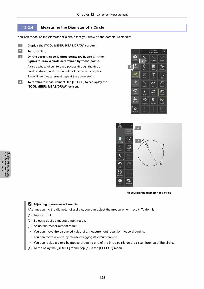
Chapter 12 On-Screen Measurement
128
Scale, A
nnotation,
and Me
asurement
Functions
12.2.4 Measuring the Diameter of a Circle
You can measure the diameter of a circle that you draw on the screen. To do this:
1 Display the [TOOL MENU: MEAS/DRAW] screen.
2 Tap [CIRCLE].
3 On the screen, specify three points (A, B, and C in the
figure) to draw a circle determined by those points.
A circle whose circumference passes through the three
points is drawn, and the diameter of the circle is displayed.
To continue measurement, repeat the above steps.
4 To terminate measurement, tap [CLOSE] to redisplay the
[TOOL MENU: MEAS/DRAW] screen.
Measuring the diameter of a circle
Adjusting measurement results
After measuring the diameter of a circle, you can adjust the measurement result. To do this:
(1) Tap [SELECT].
(2) Select a desired measurement result.
(3) Adjust the measurement result.
- You can move the displayed value of a measurement result by mouse dragging.
- You can move a circle by mouse-dragging its circumference.
- You can resize a circle by mouse-dragging one of the three points on the circumference of the circle.
(4) To redisplay the [CIRCLE] menu, tap [X] in the [SELECT] menu.
3
1
2
4
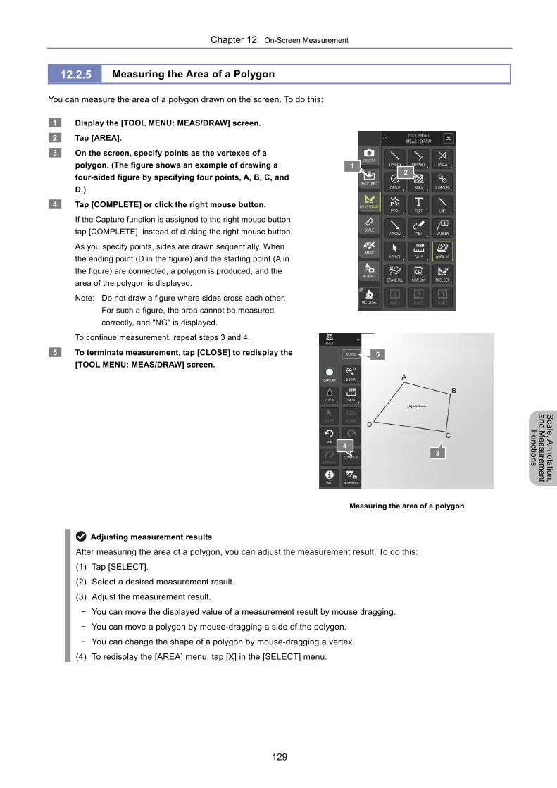
Chapter 12 On-Screen Measurement
129
Scale, A
nnotation,
and Me
asurement
Functions
12.2.5 Measuring the Area of a Polygon
You can measure the area of a polygon drawn on the screen. To do this:
1 Display the [TOOL MENU: MEAS/DRAW] screen.
2 Tap [AREA].
3 On the screen, specify points as the vertexes of a
polygon. (The figure shows an example of drawing a
four-sided figure by specifying four points, A, B, C, and
D.)
4 Tap [COMPLETE] or click the right mouse button.
If the Capture function is assigned to the right mouse button,
tap [COMPLETE], instead of clicking the right mouse button.
As you specify points, sides are drawn sequentially. When
the ending point (D in the figure) and the starting point (A in
the figure) are connected, a polygon is produced, and the
area of the polygon is displayed.
Note: Do not draw a figure where sides cross each other.
For such a figure, the area cannot be measured
correctly, and "NG" is displayed.
To continue measurement, repeat steps 3 and 4.
5 To terminate measurement, tap [CLOSE] to redisplay the
[TOOL MENU: MEAS/DRAW] screen.
Measuring the area of a polygon
Adjusting measurement results
After measuring the area of a polygon, you can adjust the measurement result. To do this:
(1) Tap [SELECT].
(2) Select a desired measurement result.
(3) Adjust the measurement result.
- You can move the displayed value of a measurement result by mouse dragging.
- You can move a polygon by mouse-dragging a side of the polygon.
- You can change the shape of a polygon by mouse-dragging a vertex.
(4) To redisplay the [AREA] menu, tap [X] in the [SELECT] menu.
4
1
3
5
2
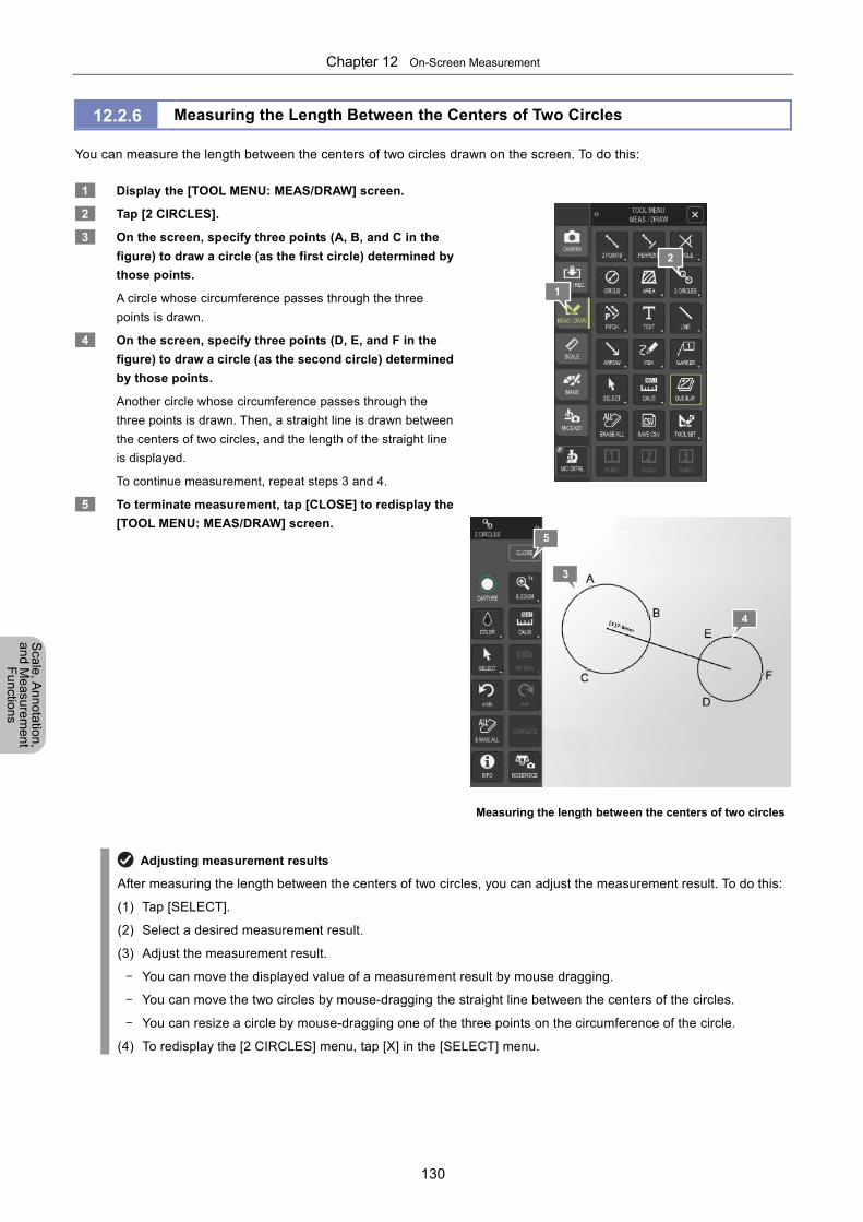
Chapter 12 On-Screen Measurement
130
Scale, A
nnotation,
and Me
asurement
Functions
12.2.6 Measuring the Length Between the Centers of Two Circles
You can measure the length between the centers of two circles drawn on the screen. To do this:
1 Display the [TOOL MENU: MEAS/DRAW] screen.
2 Tap [2 CIRCLES].
3 On the screen, specify three points (A, B, and C in the
figure) to draw a circle (as the first circle) determined by
those points.
A circle whose circumference passes through the three
points is drawn.
4 On the screen, specify three points (D, E, and F in the
figure) to draw a circle (as the second circle) determined
by those points.
Another circle whose circumference passes through the
three points is drawn. Then, a straight line is drawn between
the centers of two circles, and the length of the straight line
is displayed.
To continue measurement, repeat steps 3 and 4.
5 To terminate measurement, tap [CLOSE] to redisplay the
[TOOL MENU: MEAS/DRAW] screen.
Measuring the length between the centers of two circles
Adjusting measurement results
After measuring the length between the centers of two circles, you can adjust the measurement result. To do this:
(1) Tap [SELECT].
(2) Select a desired measurement result.
(3) Adjust the measurement result.
- You can move the displayed value of a measurement result by mouse dragging.
- You can move the two circles by mouse-dragging the straight line between the centers of the circles.
- You can resize a circle by mouse-dragging one of the three points on the circumference of the circle.
(4) To redisplay the [2 CIRCLES] menu, tap [X] in the [SELECT] menu.
3
4
1
2
5
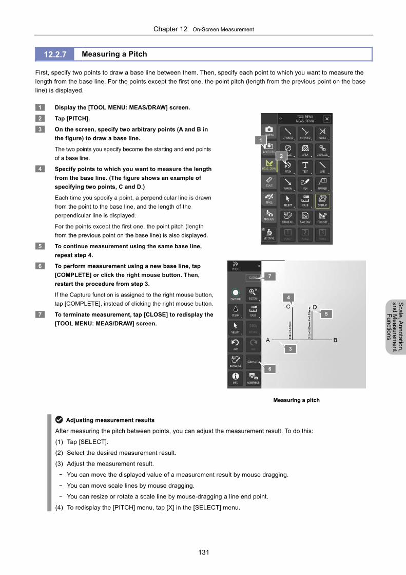
Chapter 12 On-Screen Measurement
131
Scale, A
nnotation,
and Me
asurement
Functions
12.2.7 Measuring a Pitch
First, specify two points to draw a base line between them. Then, specify each point to which you want to measure the
length from the base line. For the points except the first one, the point pitch (length from the previous point on the base
line) is displayed.
1 Display the [TOOL MENU: MEAS/DRAW] screen.
2 Tap [PITCH].
3 On the screen, specify two arbitrary points (A and B in
the figure) to draw a base line.
The two points you specify become the starting and end points
of a base line.
4 Specify points to which you want to measure the length
from the base line. (The figure shows an example of
specifying two points, C and D.)
Each time you specify a point, a perpendicular line is drawn
from the point to the base line, and the length of the
perpendicular line is displayed.
For the points except the first one, the point pitch (length
from the previous point on the base line) is also displayed.
5 To continue measurement using the same base line,
repeat step 4.
6 To perform measurement using a new base line, tap
[COMPLETE] or click the right mouse button. Then,
restart the procedure from step 3.
If the Capture function is assigned to the right mouse button,
tap [COMPLETE], instead of clicking the right mouse button.
7 To terminate measurement, tap [CLOSE] to redisplay the
[TOOL MENU: MEAS/DRAW] screen.
Measuring a pitch
Adjusting measurement results
After measuring the pitch between points, you can adjust the measurement result. To do this:
(1) Tap [SELECT].
(2) Select the desired measurement result.
(3) Adjust the measurement result.
- You can move the displayed value of a measurement result by mouse dragging.
- You can move scale lines by mouse dragging.
- You can resize or rotate a scale line by mouse-dragging a line end point.
(4) To redisplay the [PITCH] menu, tap [X] in the [SELECT] menu.
4
5
1
2
7
3
6
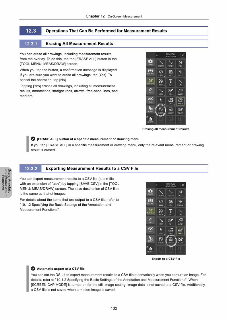
Chapter 12 On-Screen Measurement
132
Scale, A
nnotation,
and Me
asurement
Functions
12.3 Operations That Can Be Performed for Measurement Results
12.3.1 Erasing All Measurement Results
You can erase all drawings, including measurement results,
from the overlay. To do this, tap the [ERASE ALL] button in the
[TOOL MENU: MEAS/DRAW] screen.
When you tap the button, a confirmation message is displayed.
If you are sure you want to erase all drawings, tap [Yes]. To
cancel the operation, tap [No].
Tapping [Yes] erases all drawings, including all measurement
results, annotations, straight lines, arrows, free-hand lines, and
markers.
Erasing all measurement results
[ERASE ALL] button of a specific measurement or drawing menu
If you tap [ERASE ALL] in a specific measurement or drawing menu, only the relevant measurement or drawing
result is erased.
12.3.2 Exporting Measurement Results to a CSV File
You can export measurement results to a CSV file (a text file
with an extension of ".csv") by tapping [SAVE CSV] in the [TOOL
MENU: MEAS/DRAW] screen. The save destination of CSV files
is the same as that of images.
For details about the items that are output to a CSV file, refer to
"10.1.2 Specifying the Basic Settings of the Annotation and
Measurement Functions".
Export to a CSV file
Automatic export of a CSV file
You can set the DS-L4 to export measurement results to a CSV file automatically when you capture an image. For
details, refer to "10.1.2 Specifying the Basic Settings of the Annotation and Measurement Functions". When
[SCREEN CAP MODE] is turned on for the still image setting, image data is not saved to a CSV file. Additionally,
a CSV file is not saved when a motion image is saved.
Chapter 13 Changing Settings
133
Ch
an
gin
g
Se
tting
s
Part 5
Changing Settings This part describes how to change the initial settings of the DS-L4 by using the [DS SETUP] menu.
This part consists of the following chapters:
Chapter 13 Changing Settings
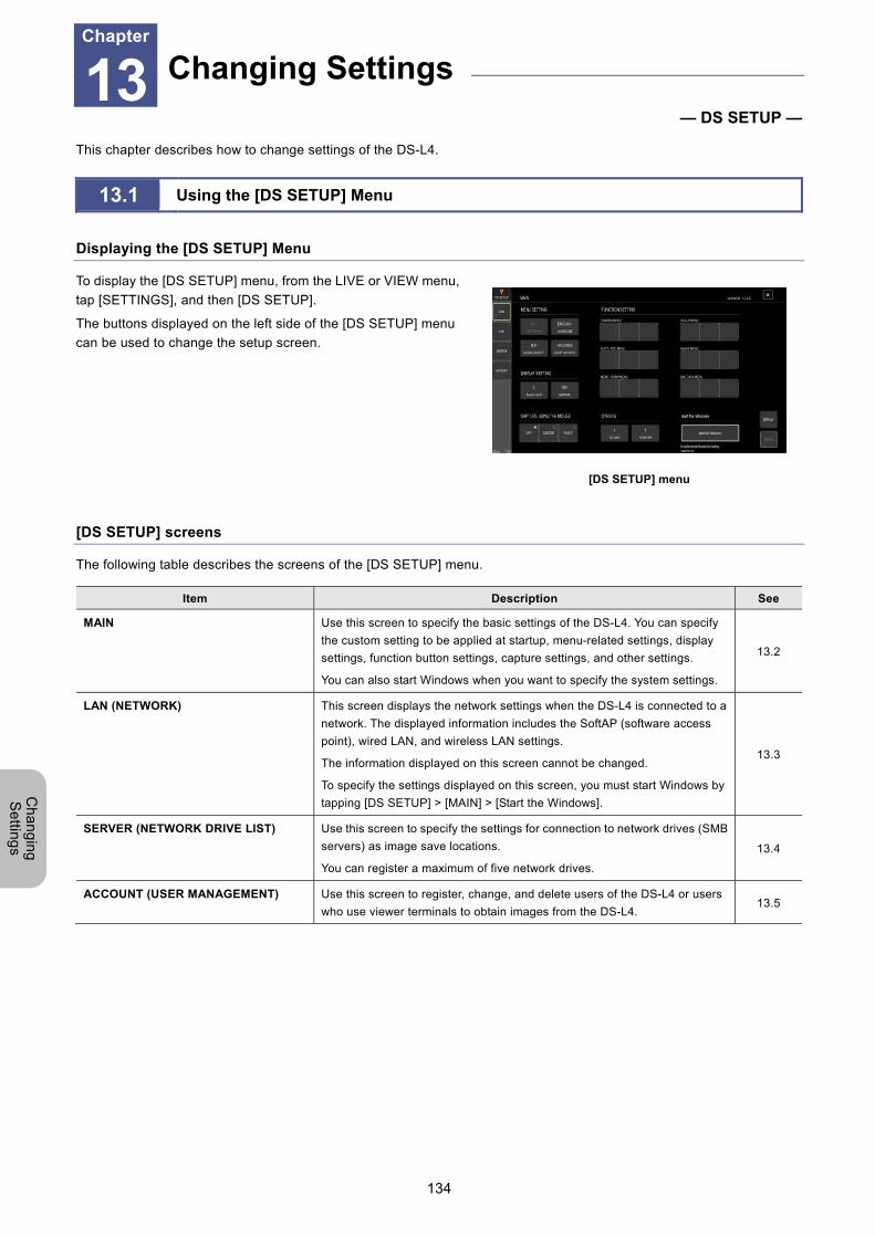
Chapter 13 Changing Settings
134
Ch
an
gin
g
Se
tting
s
13 Changing Settings
— DS SETUP —
This chapter describes how to change settings of the DS-L4.
13.1 Using the [DS SETUP] Menu
Displaying the [DS SETUP] Menu
To display the [DS SETUP] menu, from the LIVE or VIEW menu,
tap [SETTINGS], and then [DS SETUP].
The buttons displayed on the left side of the [DS SETUP] menu
can be used to change the setup screen.
[DS SETUP] menu
[DS SETUP] screens
The following table describes the screens of the [DS SETUP] menu.
Item Description See
MAIN Use this screen to specify the basic settings of the DS-L4. You can specify
the custom setting to be applied at startup, menu-related settings, display
settings, function button settings, capture settings, and other settings.
You can also start Windows when you want to specify the system settings.
13.2
LAN (NETWORK) This screen displays the network settings when the DS-L4 is connected to a
network. The displayed information includes the SoftAP (software access
point), wired LAN, and wireless LAN settings.
The information displayed on this screen cannot be changed.
To specify the settings displayed on this screen, you must start Windows by
tapping [DS SETUP] > [MAIN] > [Start the Windows].
13.3
SERVER (NETWORK DRIVE LIST) Use this screen to specify the settings for connection to network drives (SMB
servers) as image save locations.
You can register a maximum of five network drives.
13.4
ACCOUNT (USER MANAGEMENT) Use this screen to register, change, and delete users of the DS-L4 or users
who use viewer terminals to obtain images from the DS-L4. 13.5
Changing Settings Chapter
13
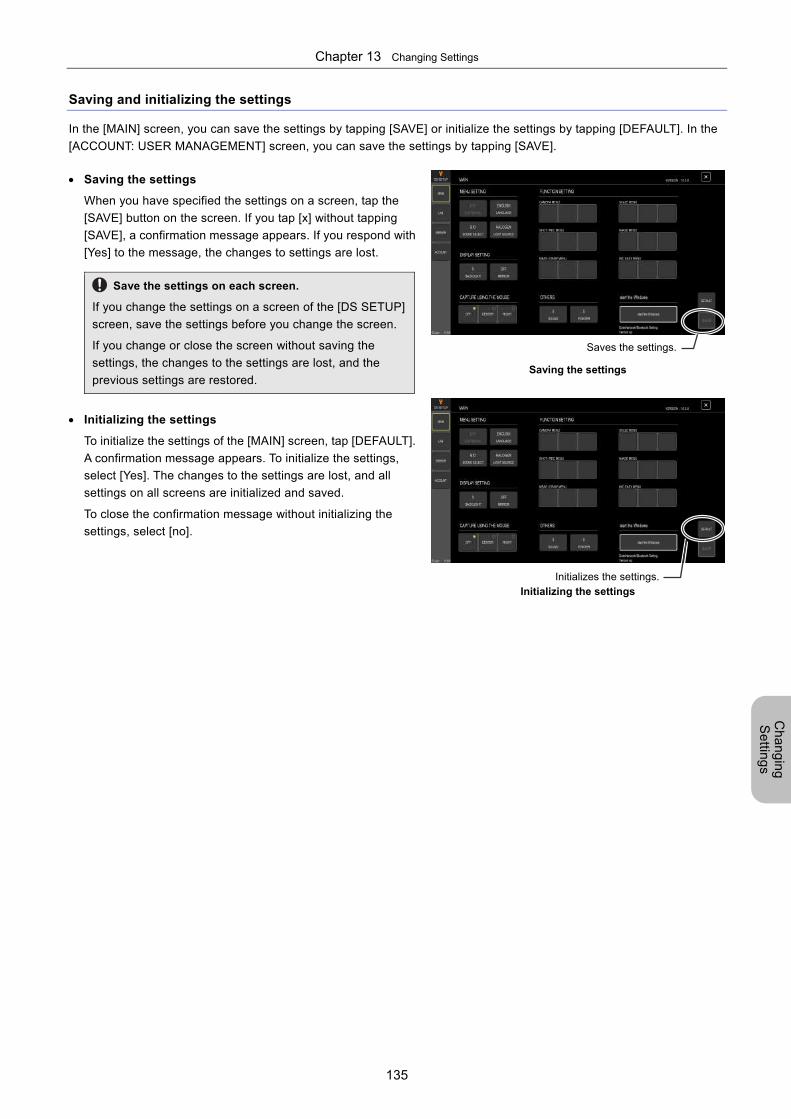
Chapter 13 Changing Settings
135
Ch
an
gin
g
Se
tting
s
Saving and initializing the settings
In the [MAIN] screen, you can save the settings by tapping [SAVE] or initialize the settings by tapping [DEFAULT]. In the
[ACCOUNT: USER MANAGEMENT] screen, you can save the settings by tapping [SAVE].
Saving the settings
When you have specified the settings on a screen, tap the
[SAVE] button on the screen. If you tap [x] without tapping
[SAVE], a confirmation message appears. If you respond with
[Yes] to the message, the changes to settings are lost.
Save the settings on each screen.
If you change the settings on a screen of the [DS SETUP]
screen, save the settings before you change the screen.
If you change or close the screen without saving the
settings, the changes to the settings are lost, and the
previous settings are restored.
Saving the settings
Initializing the settings
To initialize the settings of the [MAIN] screen, tap [DEFAULT].
A confirmation message appears. To initialize the settings,
select [Yes]. The changes to the settings are lost, and all
settings on all screens are initialized and saved.
To close the confirmation message without initializing the
settings, select [no].
Initializing the settings
Saves the settings.
Initializes the settings.
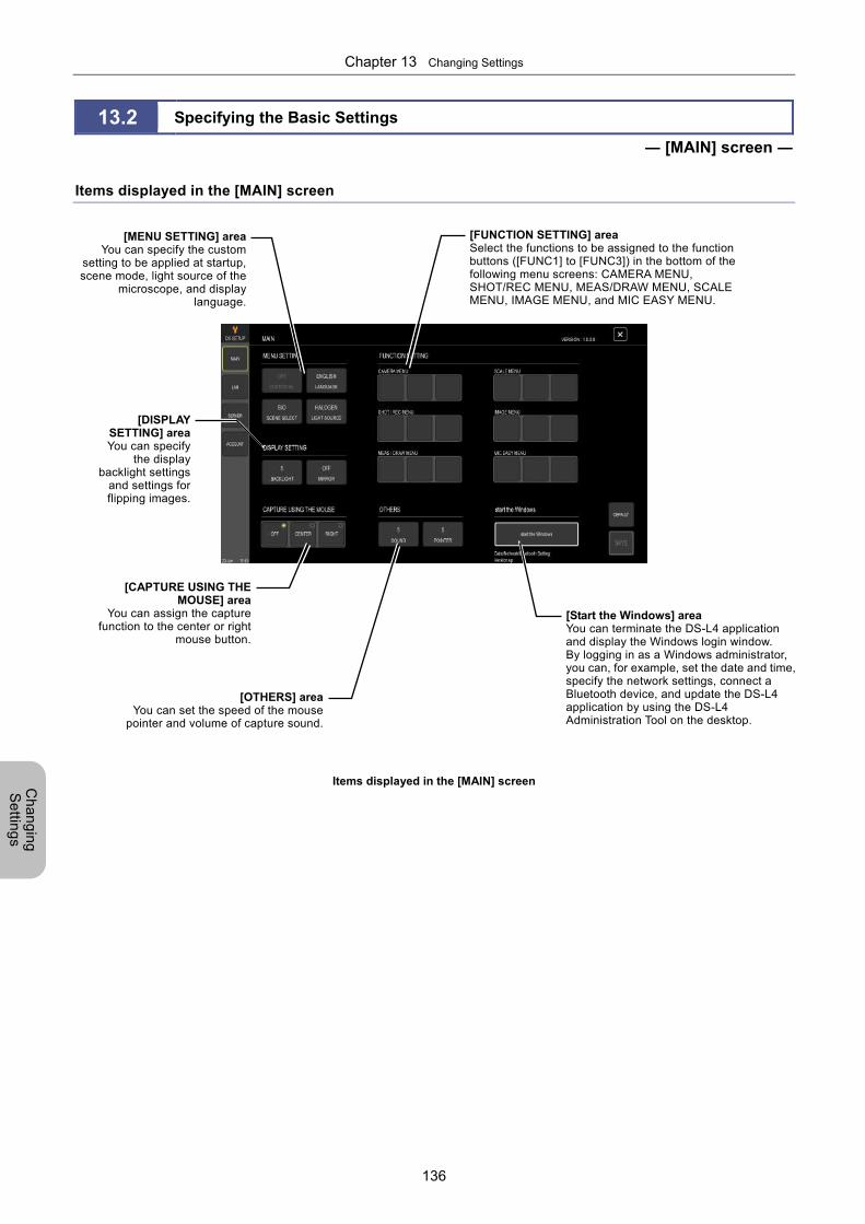
Chapter 13 Changing Settings
136
Ch
an
gin
g
Se
tting
s
13.2 Specifying the Basic Settings
― [MAIN] screen ―
Items displayed in the [MAIN] screen
Items displayed in the [MAIN] screen
[MENU SETTING] areaYou can specify the custom
setting to be applied at startup, scene mode, light source of the
microscope, and displaylanguage.
[DISPLAYSETTING] areaYou can specify
the displaybacklight settings
and settings forflipping images.
[CAPTURE USING THEMOUSE] area
You can assign the capturefunction to the center or right
mouse button.
[FUNCTION SETTING] area Select the functions to be assigned to the function buttons ([FUNC1] to [FUNC3]) in the bottom of the following menu screens: CAMERA MENU, SHOT/REC MENU, MEAS/DRAW MENU, SCALE MENU, IMAGE MENU, and MIC EASY MENU.
[OTHERS] areaYou can set the speed of the mouse
pointer and volume of capture sound.
[Start the Windows] areaYou can terminate the DS-L4 application and display the Windows login window. By logging in as a Windows administrator, you can, for example, set the date and time,specify the network settings, connect a Bluetooth device, and update the DS-L4 application by using the DS-L4 Administration Tool on the desktop.
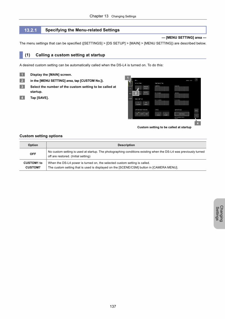
Chapter 13 Changing Settings
137
Ch
an
gin
g
Se
tting
s
13.2.1 Specifying the Menu-related Settings
— [MENU SETTING] area —
The menu settings that can be specified ([SETTINGS] > [DS SETUP] > [MAIN] > [MENU SETTING]) are described below.
(1) Calling a custom setting at startup
A desired custom setting can be automatically called when the DS-L4 is turned on. To do this:
1 Display the [MAIN] screen.
2 in the [MENU SETTING] area, tap [CUSTOM No.]).
3 Select the number of the custom setting to be called at
startup.
4 Tap [SAVE].
Custom setting to be called at startup
Custom setting options
Option Description
OFF No custom setting is used at startup. The photographing conditions existing when the DS-L4 was previously turned
off are restored. (Initial setting)
CUSTOM1 to
CUSTOM7
When the DS-L4 power is turned on, the selected custom setting is called.
The custom setting that is used is displayed on the [SCENE/CSM] button in [CAMERA MENU].
4
1
2
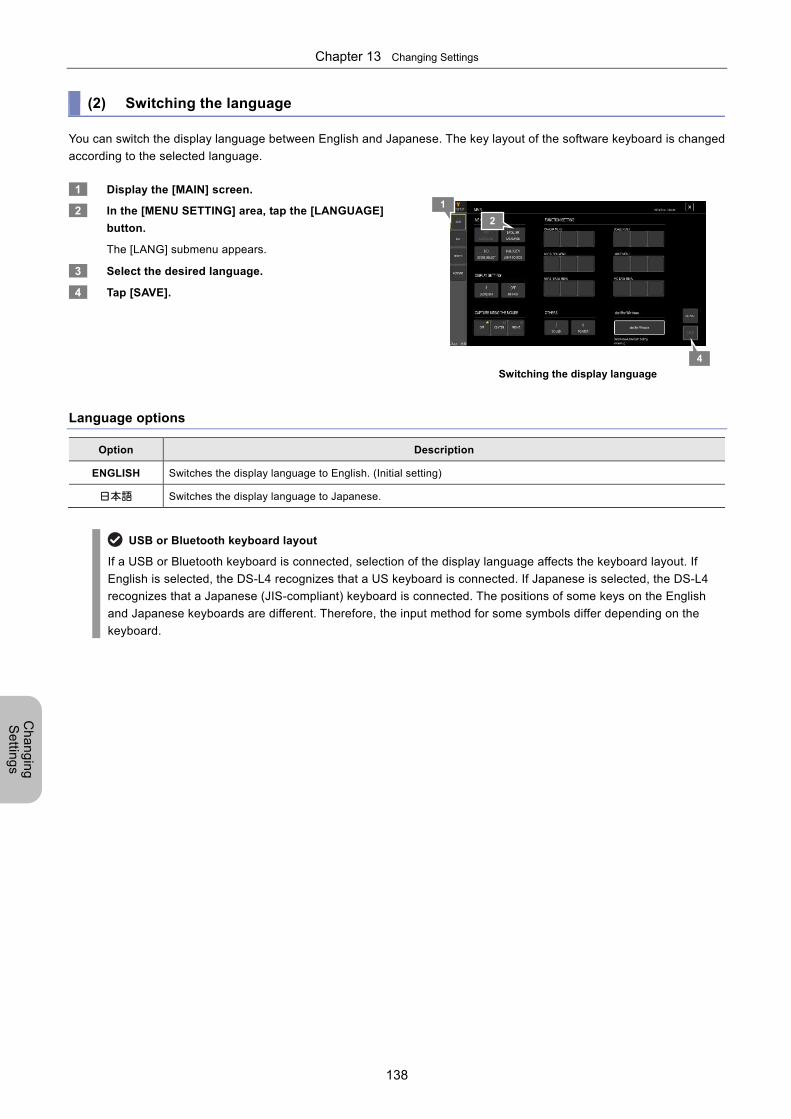
Chapter 13 Changing Settings
138
Ch
an
gin
g
Se
tting
s
(2) Switching the language
You can switch the display language between English and Japanese. The key layout of the software keyboard is changed
according to the selected language.
1 Display the [MAIN] screen.
2 In the [MENU SETTING] area, tap the [LANGUAGE]
button.
The [LANG] submenu appears.
3 Select the desired language.
4 Tap [SAVE].
Switching the display language
Language options
Option Description
ENGLISH Switches the display language to English. (Initial setting)
日本語 Switches the display language to Japanese.
USB or Bluetooth keyboard layout
If a USB or Bluetooth keyboard is connected, selection of the display language affects the keyboard layout. If
English is selected, the DS-L4 recognizes that a US keyboard is connected. If Japanese is selected, the DS-L4
recognizes that a Japanese (JIS-compliant) keyboard is connected. The positions of some keys on the English
and Japanese keyboards are different. Therefore, the input method for some symbols differ depending on the
keyboard.
4
1
2
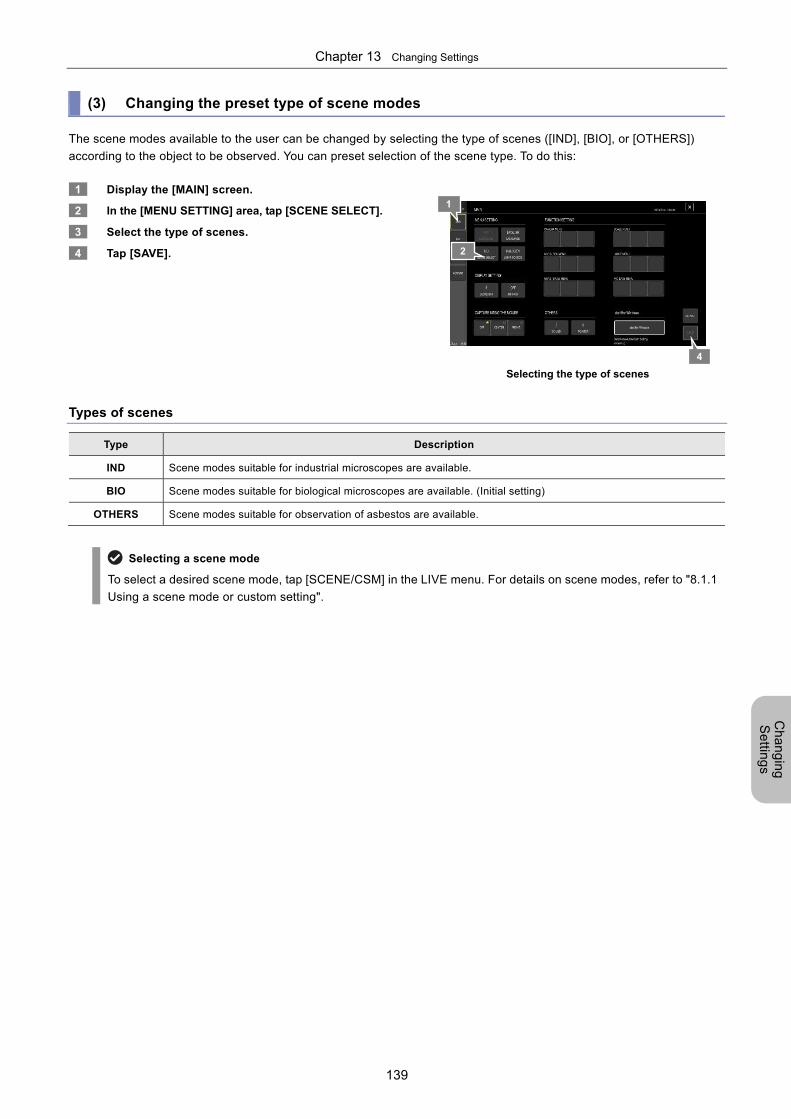
Chapter 13 Changing Settings
139
Ch
an
gin
g
Se
tting
s
(3) Changing the preset type of scene modes
The scene modes available to the user can be changed by selecting the type of scenes ([IND], [BIO], or [OTHERS])
according to the object to be observed. You can preset selection of the scene type. To do this:
1 Display the [MAIN] screen.
2 In the [MENU SETTING] area, tap [SCENE SELECT].
3 Select the type of scenes.
4 Tap [SAVE].
Selecting the type of scenes
Types of scenes
Type Description
IND Scene modes suitable for industrial microscopes are available.
BIO Scene modes suitable for biological microscopes are available. (Initial setting)
OTHERS Scene modes suitable for observation of asbestos are available.
Selecting a scene mode
To select a desired scene mode, tap [SCENE/CSM] in the LIVE menu. For details on scene modes, refer to "8.1.1
Using a scene mode or custom setting".
4
1
2
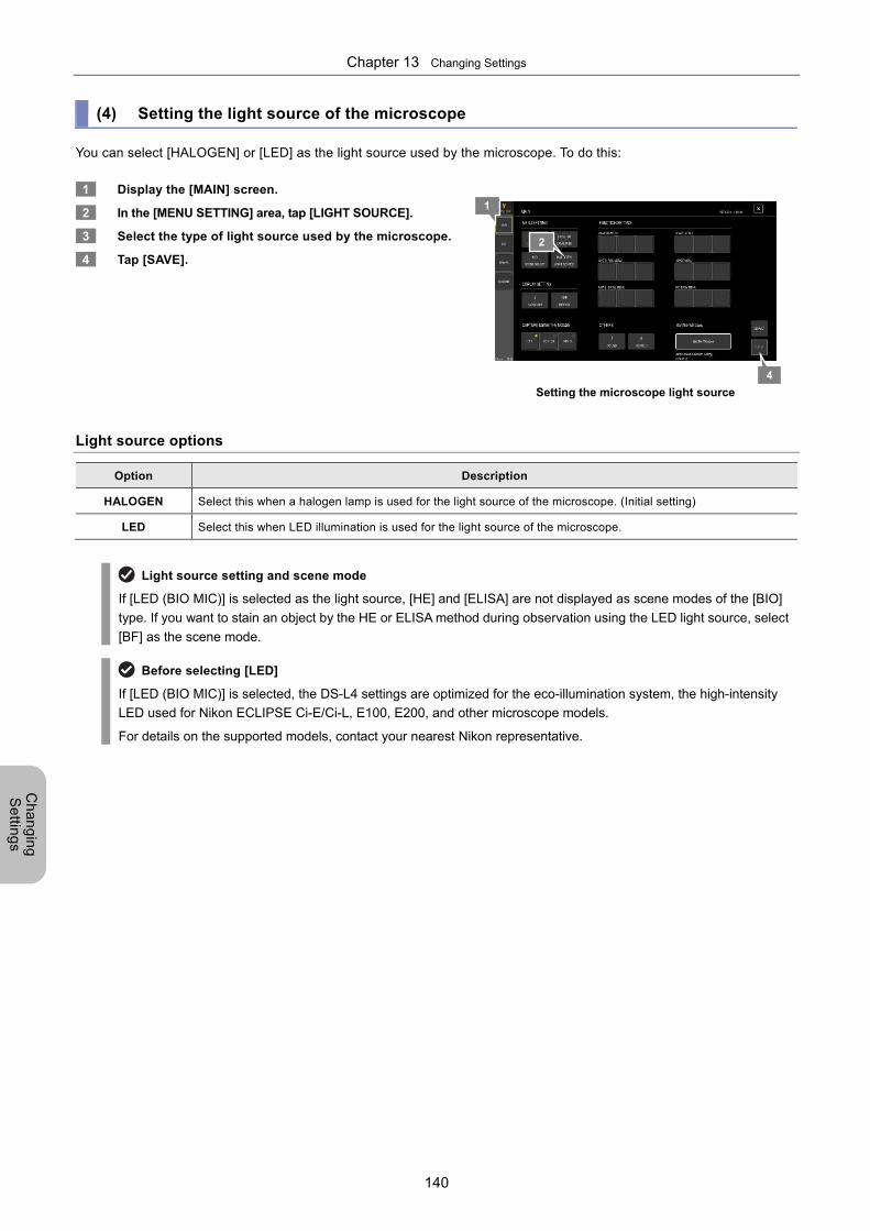
Chapter 13 Changing Settings
140
Ch
an
gin
g
Se
tting
s
(4) Setting the light source of the microscope
You can select [HALOGEN] or [LED] as the light source used by the microscope. To do this:
1 Display the [MAIN] screen.
2 In the [MENU SETTING] area, tap [LIGHT SOURCE].
3 Select the type of light source used by the microscope.
4 Tap [SAVE].
Setting the microscope light source
Light source options
Option Description
HALOGEN Select this when a halogen lamp is used for the light source of the microscope. (Initial setting)
LED Select this when LED illumination is used for the light source of the microscope.
Light source setting and scene mode
If [LED (BIO MIC)] is selected as the light source, [HE] and [ELISA] are not displayed as scene modes of the [BIO]
type. If you want to stain an object by the HE or ELISA method during observation using the LED light source, select
[BF] as the scene mode.
Before selecting [LED]
If [LED (BIO MIC)] is selected, the DS-L4 settings are optimized for the eco-illumination system, the high-intensity
LED used for Nikon ECLIPSE Ci-E/Ci-L, E100, E200, and other microscope models.
For details on the supported models, contact your nearest Nikon representative.
4
1
2
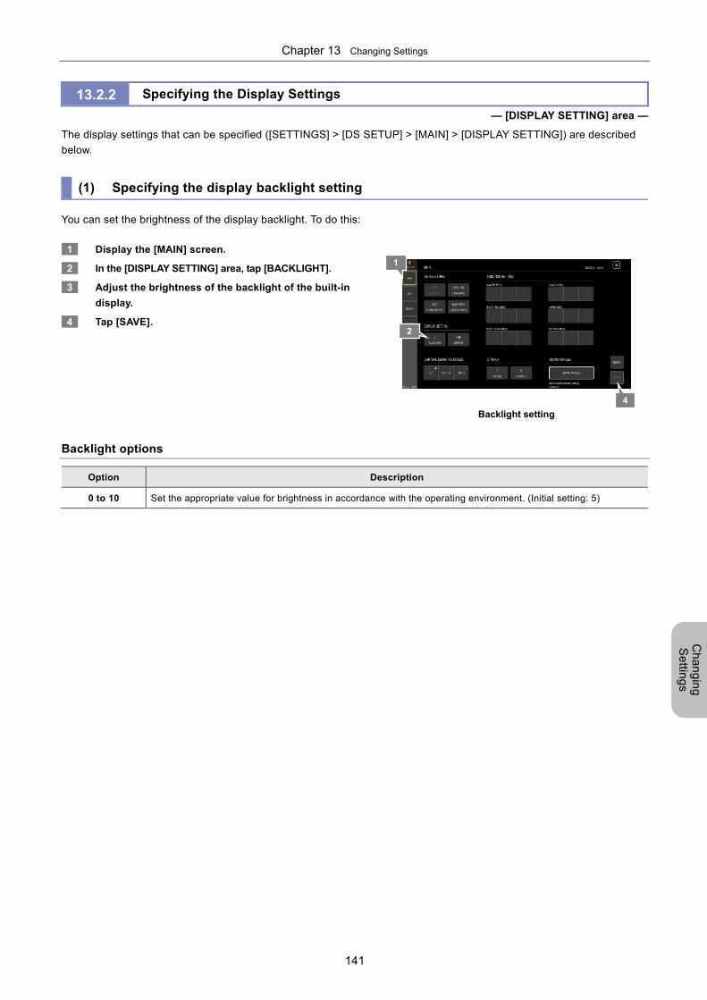
Chapter 13 Changing Settings
141
Ch
an
gin
g
Se
tting
s
13.2.2 Specifying the Display Settings
— [DISPLAY SETTING] area —
The display settings that can be specified ([SETTINGS] > [DS SETUP] > [MAIN] > [DISPLAY SETTING]) are described
below.
(1) Specifying the display backlight setting
You can set the brightness of the display backlight. To do this:
1 Display the [MAIN] screen.
2 In the [DISPLAY SETTING] area, tap [BACKLIGHT].
3 Adjust the brightness of the backlight of the built-in
display.
4 Tap [SAVE].
Backlight setting
Backlight options
Option Description
0 to 10 Set the appropriate value for brightness in accordance with the operating environment. (Initial setting: 5)
4
1
2
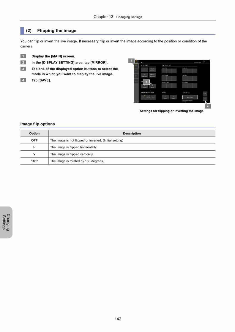
Chapter 13 Changing Settings
142
Ch
an
gin
g
Se
tting
s
(2) Flipping the image
You can flip or invert the live image. If necessary, flip or invert the image according to the position or condition of the
camera.
1 Display the [MAIN] screen.
2 In the [DISPLAY SETTING] area, tap [MIRROR].
3 Tap one of the displayed option buttons to select the
mode in which you want to display the live image.
4 Tap [SAVE].
Settings for flipping or inverting the image
Image flip options
Option Description
OFF The image is not flipped or inverted. (Initial setting)
H The image is flipped horizontally.
V The image is flipped vertically.
180° The image is rotated by 180 degrees.
4
1
2
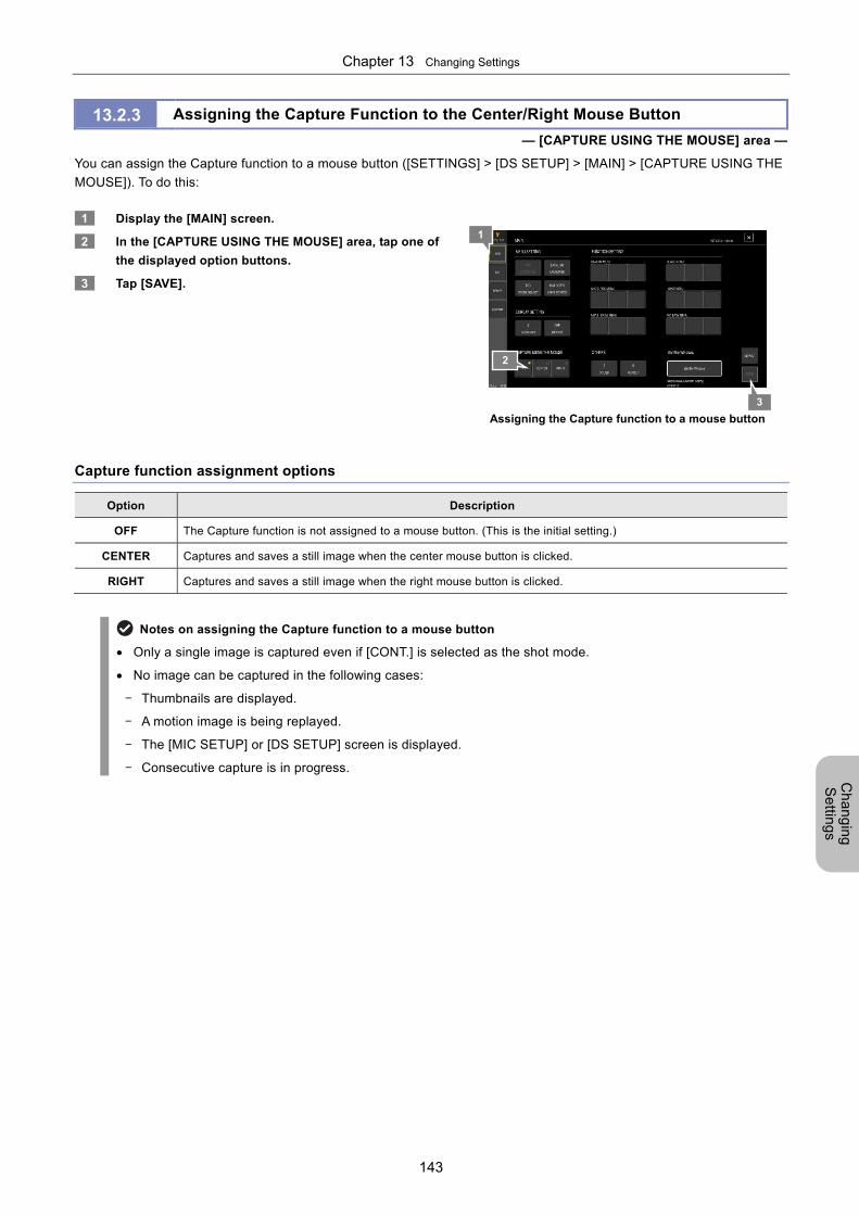
Chapter 13 Changing Settings
143
Ch
an
gin
g
Se
tting
s
13.2.3 Assigning the Capture Function to the Center/Right Mouse Button
— [CAPTURE USING THE MOUSE] area —
You can assign the Capture function to a mouse button ([SETTINGS] > [DS SETUP] > [MAIN] > [CAPTURE USING THE
MOUSE]). To do this:
1 Display the [MAIN] screen.
2 In the [CAPTURE USING THE MOUSE] area, tap one of
the displayed option buttons.
3 Tap [SAVE].
Assigning the Capture function to a mouse button
Capture function assignment options
Option Description
OFF The Capture function is not assigned to a mouse button. (This is the initial setting.)
CENTER Captures and saves a still image when the center mouse button is clicked.
RIGHT Captures and saves a still image when the right mouse button is clicked.
Notes on assigning the Capture function to a mouse button
Only a single image is captured even if [CONT.] is selected as the shot mode.
No image can be captured in the following cases:
- Thumbnails are displayed.
- A motion image is being replayed.
- The [MIC SETUP] or [DS SETUP] screen is displayed.
- Consecutive capture is in progress.
3
1
2
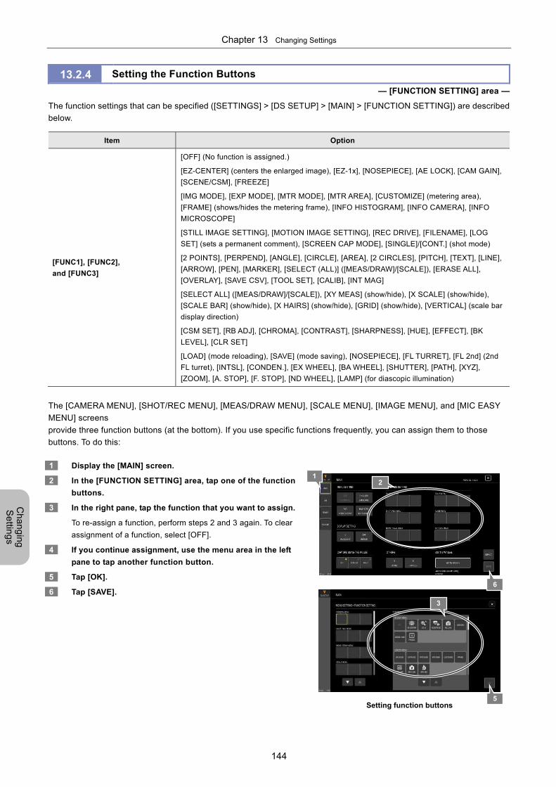
Chapter 13 Changing Settings
144
Ch
an
gin
g
Se
tting
s
13.2.4 Setting the Function Buttons
— [FUNCTION SETTING] area —
The function settings that can be specified ([SETTINGS] > [DS SETUP] > [MAIN] > [FUNCTION SETTING]) are described
below.
Item Option
[FUNC1], [FUNC2],
and [FUNC3]
[OFF] (No function is assigned.)
[EZ-CENTER] (centers the enlarged image), [EZ-1x], [NOSEPIECE], [AE LOCK], [CAM GAIN],
[SCENE/CSM], [FREEZE]
[IMG MODE], [EXP MODE], [MTR MODE], [MTR AREA], [CUSTOMIZE] (metering area),
[FRAME] (shows/hides the metering frame), [INFO HISTOGRAM], [INFO CAMERA], [INFO
MICROSCOPE]
[STILL IMAGE SETTING], [MOTION IMAGE SETTING], [REC DRIVE], [FILENAME], [LOG
SET] (sets a permanent comment), [SCREEN CAP MODE], [SINGLE]/[CONT.] (shot mode)
[2 POINTS], [PERPEND], [ANGLE], [CIRCLE], [AREA], [2 CIRCLES], [PITCH], [TEXT], [LINE],
[ARROW], [PEN], [MARKER], [SELECT (ALL)] ([MEAS/DRAW]/[SCALE]), [ERASE ALL],
[OVERLAY], [SAVE CSV], [TOOL SET], [CALIB], [INT MAG]
[SELECT ALL] ([MEAS/DRAW]/[SCALE]), [XY MEAS] (show/hide), [X SCALE] (show/hide),
[SCALE BAR] (show/hide), [X HAIRS] (show/hide), [GRID] (show/hide), [VERTICAL] (scale bar
display direction)
[CSM SET], [RB ADJ], [CHROMA], [CONTRAST], [SHARPNESS], [HUE], [EFFECT], [BK
LEVEL], [CLR SET]
[LOAD] (mode reloading), [SAVE] (mode saving), [NOSEPIECE], [FL TURRET], [FL 2nd] (2nd
FL turret), [INTSL], [CONDEN.], [EX WHEEL], [BA WHEEL], [SHUTTER], [PATH], [XYZ],
[ZOOM], [A. STOP], [F. STOP], [ND WHEEL], [LAMP] (for diascopic illumination)
The [CAMERA MENU], [SHOT/REC MENU], [MEAS/DRAW MENU], [SCALE MENU], [IMAGE MENU], and [MIC EASY
MENU] screens
provide three function buttons (at the bottom). If you use specific functions frequently, you can assign them to those
buttons. To do this:
1 Display the [MAIN] screen.
2 In the [FUNCTION SETTING] area, tap one of the function
buttons.
3 In the right pane, tap the function that you want to assign.
To re-assign a function, perform steps 2 and 3 again. To clear
assignment of a function, select [OFF].
4 If you continue assignment, use the menu area in the left
pane to tap another function button.
5 Tap [OK].
6 Tap [SAVE].
Setting function buttons
6
12
3
5
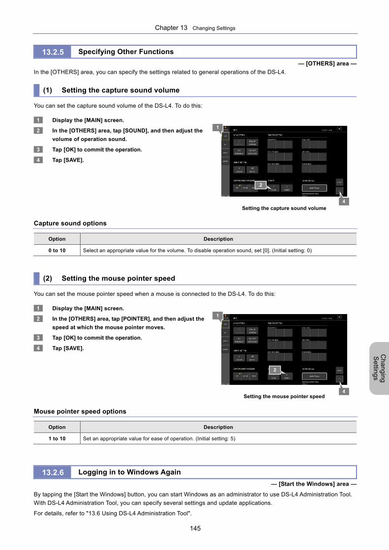
Chapter 13 Changing Settings
145
Ch
an
gin
g
Se
tting
s
13.2.5 Specifying Other Functions
— [OTHERS] area —
In the [OTHERS] area, you can specify the settings related to general operations of the DS-L4.
(1) Setting the capture sound volume You can set the capture sound volume of the DS-L4. To do this:
1 Display the [MAIN] screen.
2 In the [OTHERS] area, tap [SOUND], and then adjust the
volume of operation sound.
3 Tap [OK] to commit the operation.
4 Tap [SAVE].
Setting the capture sound volume
Capture sound options
Option Description
0 to 10 Select an appropriate value for the volume. To disable operation sound, set [0]. (Initial setting: 0)
(2) Setting the mouse pointer speed You can set the mouse pointer speed when a mouse is connected to the DS-L4. To do this:
1 Display the [MAIN] screen.
2 In the [OTHERS] area, tap [POINTER], and then adjust the
speed at which the mouse pointer moves.
3 Tap [OK] to commit the operation.
4 Tap [SAVE].
Setting the mouse pointer speed
Mouse pointer speed options
Option Description
1 to 10 Set an appropriate value for ease of operation. (Initial setting: 5)
13.2.6 Logging in to Windows Again
— [Start the Windows] area —
By tapping the [Start the Windows] button, you can start Windows as an administrator to use DS-L4 Administration Tool.
With DS-L4 Administration Tool, you can specify several settings and update applications.
For details, refer to "13.6 Using DS-L4 Administration Tool".
4
1
2
4
1
2
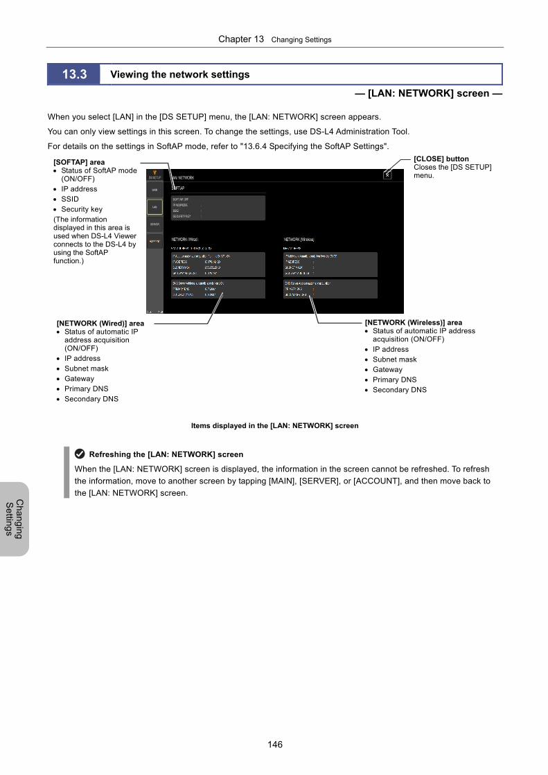
Chapter 13 Changing Settings
146
Ch
an
gin
g
Se
tting
s
13.3 Viewing the network settings
— [LAN: NETWORK] screen —
When you select [LAN] in the [DS SETUP] menu, the [LAN: NETWORK] screen appears.
You can only view settings in this screen. To change the settings, use DS-L4 Administration Tool.
For details on the settings in SoftAP mode, refer to "13.6.4 Specifying the SoftAP Settings".
Items displayed in the [LAN: NETWORK] screen
Refreshing the [LAN: NETWORK] screen
When the [LAN: NETWORK] screen is displayed, the information in the screen cannot be refreshed. To refresh
the information, move to another screen by tapping [MAIN], [SERVER], or [ACCOUNT], and then move back to
the [LAN: NETWORK] screen.
[SOFTAP] area Status of SoftAP mode
(ON/OFF) IP address SSID Security key (The information displayed in this area is used when DS-L4 Viewer connects to the DS-L4 by using the SoftAP function.)
[NETWORK (Wired)] area Status of automatic IP
address acquisition (ON/OFF)
IP address Subnet mask Gateway Primary DNS Secondary DNS
[NETWORK (Wireless)] area Status of automatic IP address
acquisition (ON/OFF) IP address Subnet mask Gateway Primary DNS Secondary DNS
[CLOSE] buttonCloses the [DS SETUP] menu.
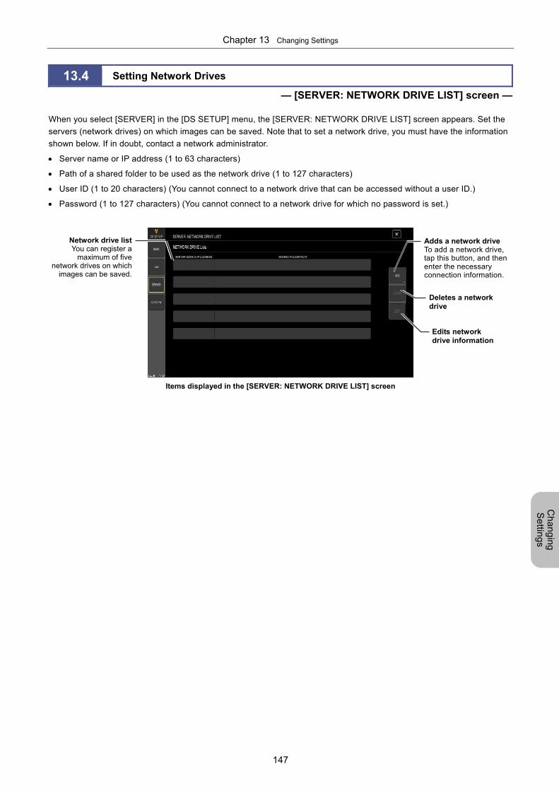
Chapter 13 Changing Settings
147
Ch
an
gin
g
Se
tting
s
13.4 Setting Network Drives
— [SERVER: NETWORK DRIVE LIST] screen —
When you select [SERVER] in the [DS SETUP] menu, the [SERVER: NETWORK DRIVE LIST] screen appears. Set the
servers (network drives) on which images can be saved. Note that to set a network drive, you must have the information
shown below. If in doubt, contact a network administrator.
Server name or IP address (1 to 63 characters)
Path of a shared folder to be used as the network drive (1 to 127 characters)
User ID (1 to 20 characters) (You cannot connect to a network drive that can be accessed without a user ID.)
Password (1 to 127 characters) (You cannot connect to a network drive for which no password is set.)
Items displayed in the [SERVER: NETWORK DRIVE LIST] screen
Adds a network drive To add a network drive, tap this button, and then enter the necessary connection information.
Deletes a network drive
Edits network drive information
Network drive listYou can register a
maximum of fivenetwork drives on which
images can be saved.
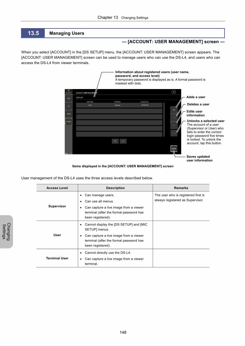
Chapter 13 Changing Settings
148
Ch
an
gin
g
Se
tting
s
13.5 Managing Users
— [ACCOUNT: USER MANAGEMENT] screen —
When you select [ACCOUNT] in the [DS SETUP] menu, the [ACCOUNT: USER MANAGEMENT] screen appears. The
[ACCOUNT: USER MANAGEMENT] screen can be used to manage users who can use the DS-L4, and users who can
access the DS-L4 from viewer terminals.
Items displayed in the [ACCOUNT: USER MANAGEMENT] screen
User management of the DS-L4 uses the three access levels described below.
Access Level Description Remarks
Supervisor
Can manage users.
Can use all menus.
Can capture a live image from a viewer
terminal (after the formal password has
been registered).
The user who is registered first is
always registered as Supervisor.
User
Cannot display the [DS SETUP] and [MIC
SETUP] menus.
Can capture a live image from a viewer
terminal (after the formal password has
been registered).
Terminal User
Cannot directly use the DS-L4.
Can capture a live image from a viewer
terminal.
Information about registered users (user name, password, and access level) A temporary password is displayed as is. A formal password ismasked with dots.
Adds a user
Deletes a user
Saves updated user information
Edits user information
Unlocks a selected userThe account of a user (Supervisor or User) who fails to enter the correct login password five times is locked. To unlock the account, tap this button.
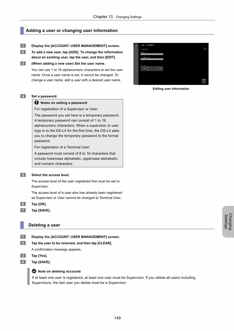
Chapter 13 Changing Settings
149
Ch
an
gin
g
Se
tting
s
Adding a user or changing user Information
1 Display the [ACCOUNT: USER MANAGEMENT] screen.
2 To add a new user, tap [ADD]. To change the information
about an existing user, tap the user, and then [EDIT].
3 (When adding a new user) Set the user name.
You can use 1 to 16 alphanumeric characters to set the user
name. Once a user name is set, it cannot be changed. To
change a user name, add a user with a desired user name.
Editing user information
4 Set a password.
Notes on setting a password
For registration of a Supervisor or User:
The password you set here is a temporary password.
A temporary password can consist of 1 to 16
alphanumeric characters. When a supervisor or user
logs in to the DS-L4 for the first time, the DS-L4 asks
you to change the temporary password to the formal
password.
For registration of a Terminal User:
A password must consist of 8 to 16 characters that
include lowercase alphabetic, uppercase alphabetic,
and numeric characters.
5 Select the access level.
The access level of the user registered first must be set to
Supervisor.
The access level of a user who has already been registered
as Supervisor or User cannot be changed to Terminal User.
6 Tap [OK].
7 Tap [SAVE].
Deleting a user
1 Display the [ACCOUNT: USER MANAGEMENT] screen.
2 Tap the user to be removed, and then tap [CLEAR].
A confirmation message appears.
3 Tap [Yes].
4 Tap [SAVE].
Note on deleting accounts
If at least one user is registered, at least one user must be Supervisor. If you delete all users including
Supervisors, the last user you delete must be a Supervisor.
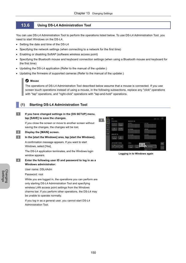
Chapter 13 Changing Settings
150
Ch
an
gin
g
Se
tting
s
13.6 Using DS-L4 Administration Tool
You can use DS-L4 Administration Tool to perform the operations listed below. To use DS-L4 Administration Tool, you
need to start Windows on the DS-L4.
Setting the date and time of the DS-L4
Specifying the network settings (when connecting to a network for the first time)
Enabling or disabling SoftAP (software wireless access point)
Specifying the Bluetooth mouse and keyboard connection settings (when using a Bluetooth mouse and keyboard for
the first time)
Updating the DS-L4 application (Refer to the manual of the updater.)
Updating the firmware of supported cameras (Refer to the manual of the updater.)
Mouse
The operations of DS-L4 Administration Tool described below assume that a mouse is connected. If you use
screen touch operations instead of using a mouse, in the following subsections, replace any "click" operations
with "tap" operations, and "right-click" operations with "tap-and-hold" operations. (1) Starting DS-L4 Administration Tool
1 If you have changed settings in the [DS SETUP] menu,
tap [SAVE] to save the changes.
If you close the screen or move to another screen without
saving the changes, the changes will be lost.
2 Display the [MAIN] screen.
3 In the [start the Windows] area, tap [start the Windows].
A confirmation message appears. If you want to start
Windows, select [Yes].
The DS-L4 application terminates, and the Windows login
window appears.
4 Enter the following user ID and password to log in as a
Windows administrator:
User name: DSL4Adm
Password: root
While you are logged in, the operations you can perform are
only starting DS-L4 Administration Tool and specifying
wireless LAN access point settings from the Windows
charms bar. If you perform other operations, the DS-L4 may
be unable to operate normally.
If you log in as a general user, you cannot start DS-L4
Administration Tool.
Logging in to Windows again
2
3
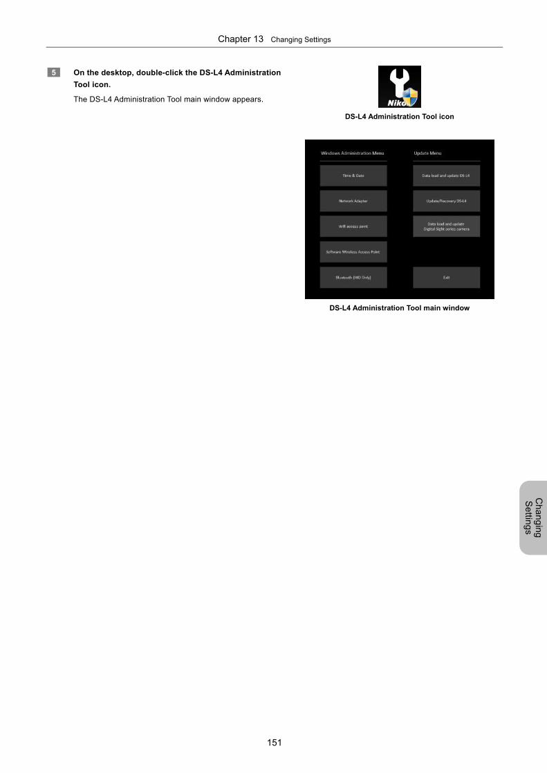
Chapter 13 Changing Settings
151
Ch
an
gin
g
Se
tting
s
5 On the desktop, double-click the DS-L4 Administration
Tool icon.
The DS-L4 Administration Tool main window appears.
DS-L4 Administration Tool icon
DS-L4 Administration Tool main window
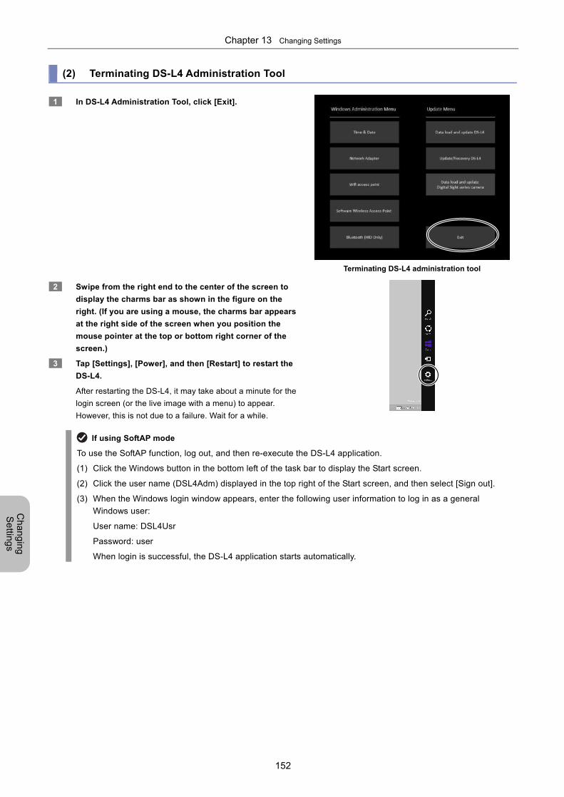
Chapter 13 Changing Settings
152
Ch
an
gin
g
Se
tting
s
(2) Terminating DS-L4 Administration Tool
1 In DS-L4 Administration Tool, click [Exit].
Terminating DS-L4 administration tool
2 Swipe from the right end to the center of the screen to
display the charms bar as shown in the figure on the
right. (If you are using a mouse, the charms bar appears
at the right side of the screen when you position the
mouse pointer at the top or bottom right corner of the
screen.)
3 Tap [Settings], [Power], and then [Restart] to restart the
DS-L4.
After restarting the DS-L4, it may take about a minute for the
login screen (or the live image with a menu) to appear.
However, this is not due to a failure. Wait for a while.
If using SoftAP mode
To use the SoftAP function, log out, and then re-execute the DS-L4 application.
(1) Click the Windows button in the bottom left of the task bar to display the Start screen.
(2) Click the user name (DSL4Adm) displayed in the top right of the Start screen, and then select [Sign out].
(3) When the Windows login window appears, enter the following user information to log in as a general
Windows user:
User name: DSL4Usr
Password: user
When login is successful, the DS-L4 application starts automatically.
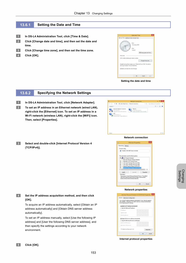
Chapter 13 Changing Settings
153
Ch
an
gin
g
Se
tting
s
13.6.1 Setting the Date and Time
1 In DS-L4 Administration Tool, click [Time & Date].
2 Click [Change date and time], and then set the date and
time.
3 Click [Change time zone], and then set the time zone.
4 Click [OK].
Setting the date and time
13.6.2 Specifying the Network Settings
1 In DS-L4 Administration Tool, click [Network Adapter].
2 To set an IP address in an Ethernet network (wired LAN),
right-click the [Ethernet] icon. To set an IP address in a
Wi-Fi network (wireless LAN), right-click the [WiFi] icon.
Then, select [Properties].
Network connection
3 Select and double-click [Internet Protocol Version 4
(TCP/IPv4)].
Network properties
4 Set the IP address acquisition method, and then click
[OK].
To acquire an IP address automatically, select [Obtain an IP
address automatically] and [Obtain DNS server address
automatically].
To set an IP address manually, select [Use the following IP
address] and [User the following DNS server address], and
then specify the settings according to your network
environment.
Internet protocol properties
5 Click [OK].
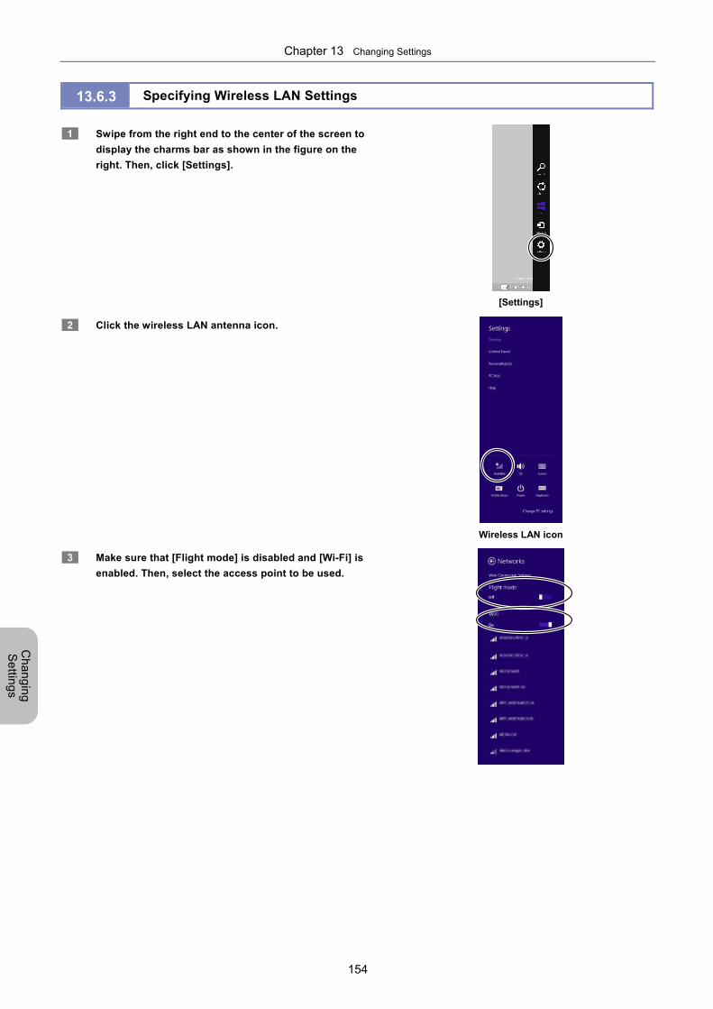
Chapter 13 Changing Settings
154
Ch
an
gin
g
Se
tting
s
13.6.3 Specifying Wireless LAN Settings
1 Swipe from the right end to the center of the screen to
display the charms bar as shown in the figure on the
right. Then, click [Settings].
[Settings]
2 Click the wireless LAN antenna icon.
Wireless LAN icon
3 Make sure that [Flight mode] is disabled and [Wi-Fi] is
enabled. Then, select the access point to be used.
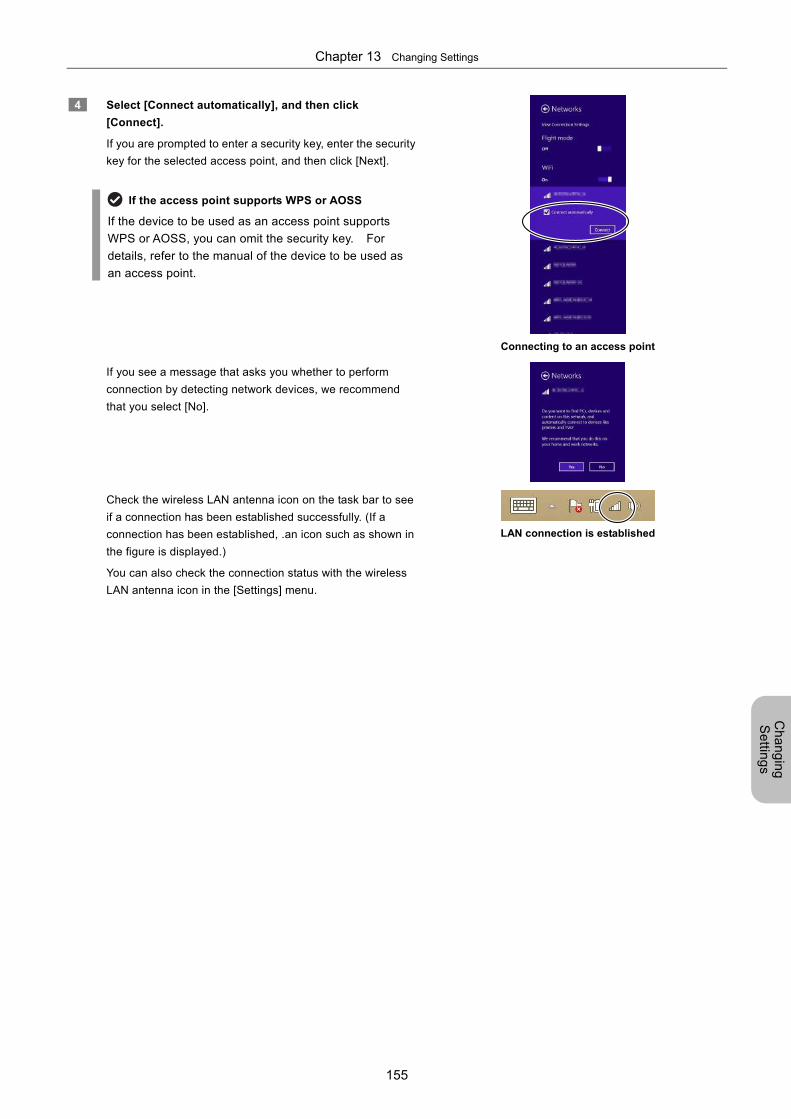
Chapter 13 Changing Settings
155
Ch
an
gin
g
Se
tting
s
4 Select [Connect automatically], and then click
[Connect].
If you are prompted to enter a security key, enter the security
key for the selected access point, and then click [Next].
If the access point supports WPS or AOSS
If the device to be used as an access point supports
WPS or AOSS, you can omit the security key. For
details, refer to the manual of the device to be used as
an access point.
Connecting to an access point
If you see a message that asks you whether to perform
connection by detecting network devices, we recommend
that you select [No].
Check the wireless LAN antenna icon on the task bar to see
if a connection has been established successfully. (If a
connection has been established, .an icon such as shown in
the figure is displayed.)
You can also check the connection status with the wireless
LAN antenna icon in the [Settings] menu.
LAN connection is established
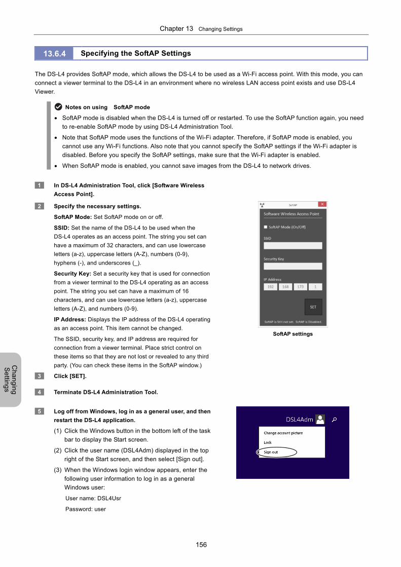
Chapter 13 Changing Settings
156
Ch
an
gin
g
Se
tting
s
13.6.4 Specifying the SoftAP Settings
The DS-L4 provides SoftAP mode, which allows the DS-L4 to be used as a Wi-Fi access point. With this mode, you can
connect a viewer terminal to the DS-L4 in an environment where no wireless LAN access point exists and use DS-L4
Viewer.
Notes on using SoftAP mode
SoftAP mode is disabled when the DS-L4 is turned off or restarted. To use the SoftAP function again, you need
to re-enable SoftAP mode by using DS-L4 Administration Tool.
Note that SoftAP mode uses the functions of the Wi-Fi adapter. Therefore, if SoftAP mode is enabled, you
cannot use any Wi-Fi functions. Also note that you cannot specify the SoftAP settings if the Wi-Fi adapter is
disabled. Before you specify the SoftAP settings, make sure that the Wi-Fi adapter is enabled.
When SoftAP mode is enabled, you cannot save images from the DS-L4 to network drives.
1 In DS-L4 Administration Tool, click [Software Wireless
Access Point].
2 Specify the necessary settings.
SoftAP Mode: Set SoftAP mode on or off.
SSID: Set the name of the DS-L4 to be used when the
DS-L4 operates as an access point. The string you set can
have a maximum of 32 characters, and can use lowercase
letters (a-z), uppercase letters (A-Z), numbers (0-9),
hyphens (-), and underscores (_).
Security Key: Set a security key that is used for connection
from a viewer terminal to the DS-L4 operating as an access
point. The string you set can have a maximum of 16
characters, and can use lowercase letters (a-z), uppercase
letters (A-Z), and numbers (0-9).
IP Address: Displays the IP address of the DS-L4 operating
as an access point. This item cannot be changed.
The SSID, security key, and IP address are required for
connection from a viewer terminal. Place strict control on
these items so that they are not lost or revealed to any third
party. (You can check these items in the SoftAP window.)
SoftAP settings
3 Click [SET].
4 Terminate DS-L4 Administration Tool.
5 Log off from Windows, log in as a general user, and then
restart the DS-L4 application.
(1) Click the Windows button in the bottom left of the task
bar to display the Start screen.
(2) Click the user name (DSL4Adm) displayed in the top
right of the Start screen, and then select [Sign out].
(3) When the Windows login window appears, enter the
following user information to log in as a general
Windows user:
User name: DSL4Usr
Password: user
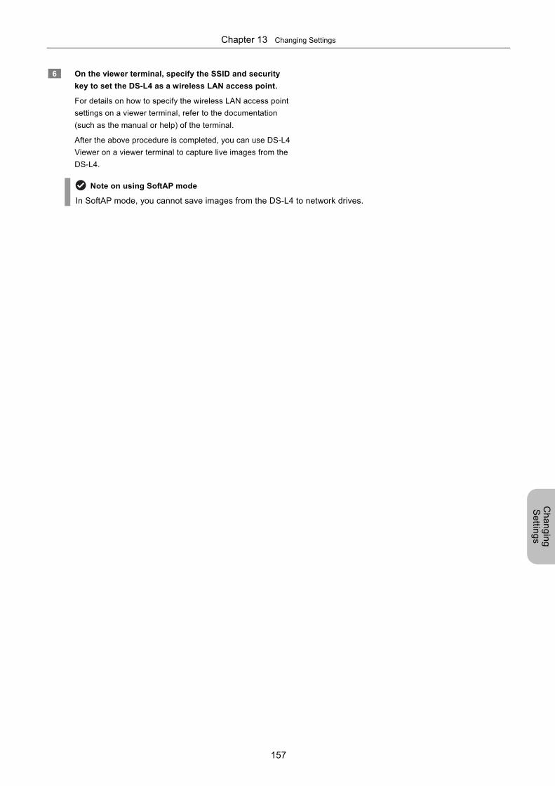
Chapter 13 Changing Settings
157
Ch
an
gin
g
Se
tting
s
6 On the viewer terminal, specify the SSID and security
key to set the DS-L4 as a wireless LAN access point.
For details on how to specify the wireless LAN access point
settings on a viewer terminal, refer to the documentation
(such as the manual or help) of the terminal.
After the above procedure is completed, you can use DS-L4
Viewer on a viewer terminal to capture live images from the
DS-L4.
Note on using SoftAP mode
In SoftAP mode, you cannot save images from the DS-L4 to network drives.
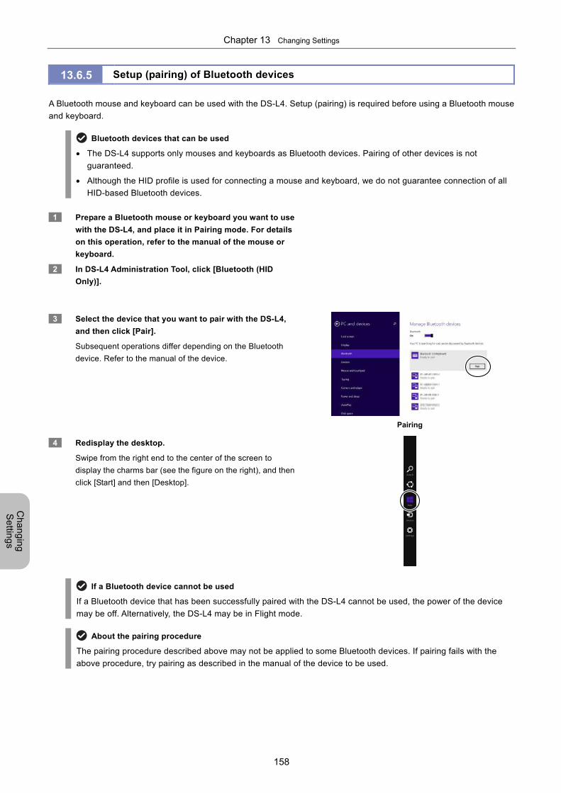
Chapter 13 Changing Settings
158
Ch
an
gin
g
Se
tting
s
13.6.5 Setup (pairing) of Bluetooth devices
A Bluetooth mouse and keyboard can be used with the DS-L4. Setup (pairing) is required before using a Bluetooth mouse
and keyboard.
Bluetooth devices that can be used
The DS-L4 supports only mouses and keyboards as Bluetooth devices. Pairing of other devices is not
guaranteed.
Although the HID profile is used for connecting a mouse and keyboard, we do not guarantee connection of all
HID-based Bluetooth devices.
1 Prepare a Bluetooth mouse or keyboard you want to use
with the DS-L4, and place it in Pairing mode. For details
on this operation, refer to the manual of the mouse or
keyboard.
2 In DS-L4 Administration Tool, click [Bluetooth (HID
Only)].
3 Select the device that you want to pair with the DS-L4,
and then click [Pair].
Subsequent operations differ depending on the Bluetooth
device. Refer to the manual of the device.
Pairing
4 Redisplay the desktop.
Swipe from the right end to the center of the screen to
display the charms bar (see the figure on the right), and then
click [Start] and then [Desktop].
If a Bluetooth device cannot be used
If a Bluetooth device that has been successfully paired with the DS-L4 cannot be used, the power of the device
may be off. Alternatively, the DS-L4 may be in Flight mode.
About the pairing procedure
The pairing procedure described above may not be applied to some Bluetooth devices. If pairing fails with the
above procedure, try pairing as described in the manual of the device to be used.
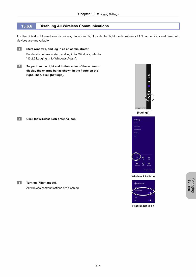
Chapter 13 Changing Settings
159
Ch
an
gin
g
Se
tting
s
13.6.6 Disabling All Wireless Communications
For the DS-L4 not to emit electric waves, place it in Flight mode. In Flight mode, wireless LAN connections and Bluetooth
devices are unavailable.
1 Start Windows, and log in as an administrator.
For details on how to start, and log in to, Windows, refer to
"13.2.6 Logging in to Windows Again".
2 Swipe from the right end to the center of the screen to
display the charms bar as shown in the figure on the
right. Then, click [Settings].
[Settings]
3 Click the wireless LAN antenna icon.
Wireless LAN icon
4 Turn on [Flight mode].
All wireless communications are disabled.
Flight mode is on

Chapter 13 Changing Settings
160
Ch
an
gin
g
Se
tting
s
Chapter 14 About Microscope Digital Cameras
161
Oth
er
Info
rma
tion
Part 6
Other Information This part provides various kinds of information required to operate the DS-L4.
This part consists of the following chapters:
Chapter 14 About Microscope Digital Cameras
Chapter 15 Connecting to a Network (LAN)
Chapter 16 Troubleshooting
Chapter 17 Performing Captures from an External Device
Chapter 18 Using the Diagnostic Program
Chapter 19 Daily Maintenance
Chapter 20 Main Specifications
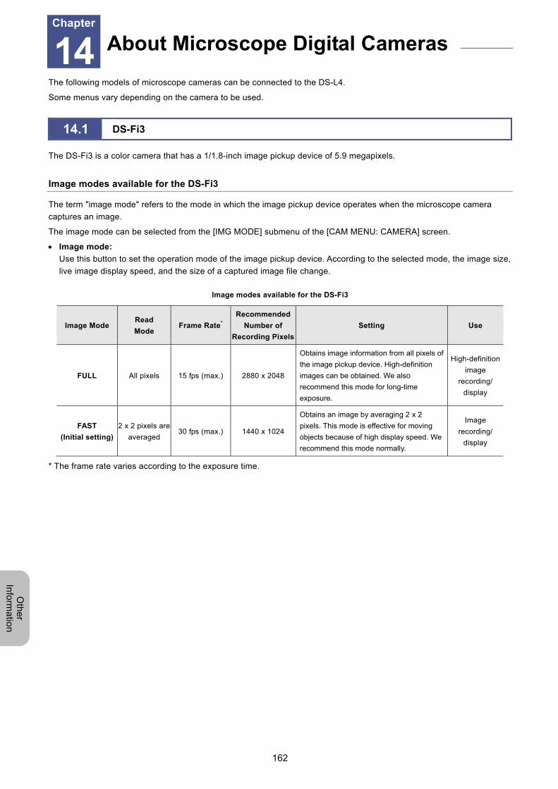
Chapter 14 About Microscope Digital Cameras
162
Oth
er
Info
rma
tion
14 About Microscope Digital Cameras
The following models of microscope cameras can be connected to the DS-L4.
Some menus vary depending on the camera to be used.
14.1 DS-Fi3
The DS-Fi3 is a color camera that has a 1/1.8-inch image pickup device of 5.9 megapixels.
Image modes available for the DS-Fi3
The term "image mode" refers to the mode in which the image pickup device operates when the microscope camera
captures an image.
The image mode can be selected from the [IMG MODE] submenu of the [CAM MENU: CAMERA] screen.
Image mode:
Use this button to set the operation mode of the image pickup device. According to the selected mode, the image size,
live image display speed, and the size of a captured image file change.
Image modes available for the DS-Fi3
Image Mode Read
Mode Frame Rate*
Recommended
Number of
Recording Pixels
Setting Use
FULL All pixels 15 fps (max.) 2880 x 2048
Obtains image information from all pixels of
the image pickup device. High-definition
images can be obtained. We also
recommend this mode for long-time
exposure.
High-definition
image
recording/
display
FAST
(Initial setting)
2 x 2 pixels are
averaged 30 fps (max.) 1440 x 1024
Obtains an image by averaging 2 x 2
pixels. This mode is effective for moving
objects because of high display speed. We
recommend this mode normally.
Image
recording/
display
* The frame rate varies according to the exposure time.
About Microscope Digital Cameras Chapter
14
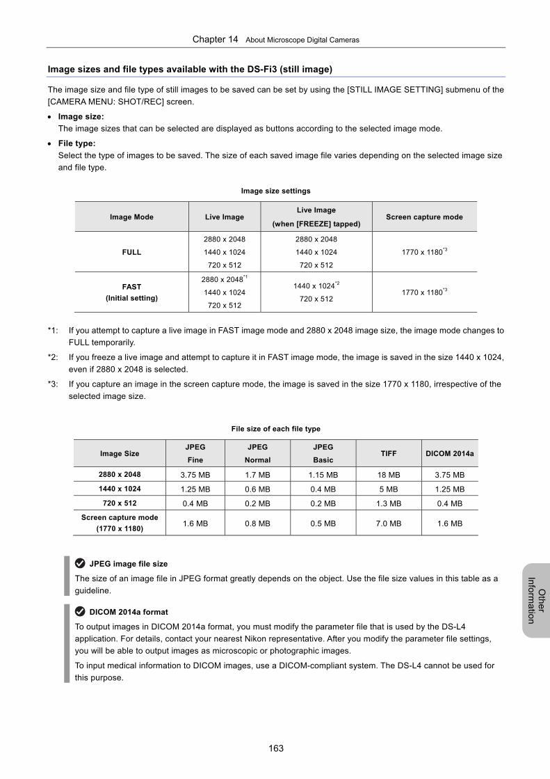
Chapter 14 About Microscope Digital Cameras
163
Oth
er
Info
rma
tion
Image sizes and file types available with the DS-Fi3 (still image)
The image size and file type of still images to be saved can be set by using the [STILL IMAGE SETTING] submenu of the
[CAMERA MENU: SHOT/REC] screen.
Image size:
The image sizes that can be selected are displayed as buttons according to the selected image mode.
File type:
Select the type of images to be saved. The size of each saved image file varies depending on the selected image size
and file type.
Image size settings
Image Mode Live Image Live Image
(when [FREEZE] tapped) Screen capture mode
FULL
2880 x 2048
1440 x 1024
720 x 512
2880 x 2048
1440 x 1024
720 x 512
1770 x 1180*3
FAST
(Initial setting)
2880 x 2048*1
1440 x 1024
720 x 512
1440 x 1024*2
720 x 512 1770 x 1180*3
*1: If you attempt to capture a live image in FAST image mode and 2880 x 2048 image size, the image mode changes to
FULL temporarily.
*2: If you freeze a live image and attempt to capture it in FAST image mode, the image is saved in the size 1440 x 1024,
even if 2880 x 2048 is selected.
*3: If you capture an image in the screen capture mode, the image is saved in the size 1770 x 1180, irrespective of the
selected image size.
File size of each file type
Image Size JPEG
Fine
JPEG
Normal
JPEG
Basic TIFF DICOM 2014a
2880 x 2048 3.75 MB 1.7 MB 1.15 MB 18 MB 3.75 MB
1440 x 1024 1.25 MB 0.6 MB 0.4 MB 5 MB 1.25 MB
720 x 512 0.4 MB 0.2 MB 0.2 MB 1.3 MB 0.4 MB
Screen capture mode
(1770 x 1180) 1.6 MB 0.8 MB 0.5 MB 7.0 MB 1.6 MB
JPEG image file size
The size of an image file in JPEG format greatly depends on the object. Use the file size values in this table as a
guideline.
DICOM 2014a format
To output images in DICOM 2014a format, you must modify the parameter file that is used by the DS-L4
application. For details, contact your nearest Nikon representative. After you modify the parameter file settings,
you will be able to output images as microscopic or photographic images.
To input medical information to DICOM images, use a DICOM-compliant system. The DS-L4 cannot be used for
this purpose.
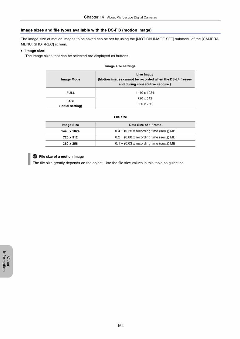
Chapter 14 About Microscope Digital Cameras
164
Oth
er
Info
rma
tion
Image sizes and file types available with the DS-Fi3 (motion image)
The image size of motion images to be saved can be set by using the [MOTION IMAGE SET] submenu of the [CAMERA
MENU: SHOT/REC] screen.
Image size:
The image sizes that can be selected are displayed as buttons.
Image size settings
Image Mode
Live Image
(Motion images cannot be recorded when the DS-L4 freezes
and during consecutive capture.)
FULL 1440 x 1024
720 x 512
360 x 256 FAST
(Initial setting)
File size
Image Size Data Size of 1 Frame
1440 x 1024 0.4 + (0.25 x recording time (sec.)) MB
720 x 512 0.2 + (0.08 x recording time (sec.)) MB
360 x 256 0.1 + (0.03 x recording time (sec.)) MB
File size of a motion image
The file size greatly depends on the object. Use the file size values in this table as guideline.
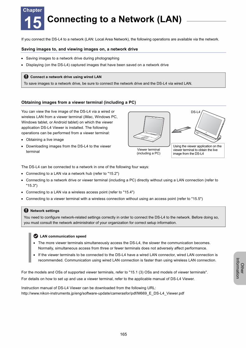
Chapter 15 Connecting to a Network (LAN)
165
Oth
er
Info
rma
tion
15 Connecting to a Network (LAN)
If you connect the DS-L4 to a network (LAN: Local Area Network), the following operations are available via the network.
Saving images to, and viewing images on, a network drive
Saving images to a network drive during photographing
Displaying (on the DS-L4) captured images that have been saved on a network drive
Connect a network drive using wired LAN
To save images to a network drive, be sure to connect the network drive and the DS-L4 via wired LAN.
Obtaining images from a viewer terminal (including a PC)
You can view the live image of the DS-L4 via a wired or
wireless LAN from a viewer terminal (iMac, Windows PC,
Windows tablet, or Android tablet) on which the viewer
application DS-L4 Viewer is installed. The following
operations can be performed from a viewer terminal:
Obtaining a live image
Downloading images from the DS-L4 to the viewer
terminal
The DS-L4 can be connected to a network in one of the following four ways:
Connecting to a LAN via a network hub (refer to "15.2")
Connecting to a network drive or viewer terminal (including a PC) directly without using a LAN connection (refer to
"15.3")
Connecting to a LAN via a wireless access point (refer to "15.4")
Connecting to a viewer terminal with a wireless connection without using an access point (refer to "15.5")
Network settings
You need to configure network-related settings correctly in order to connect the DS-L4 to the network. Before doing so,
you must consult the network administrator of your organization for correct setup information.
LAN communication speed
The more viewer terminals simultaneously access the DS-L4, the slower the communication becomes.
Normally, simultaneous access from three or fewer terminals does not adversely affect performance.
If the viewer terminals to be connected to the DS-L4 have a wired LAN connector, wired LAN connection is
recommended. Communication using wired LAN connection is faster than using wireless LAN connection.
For the models and OSs of supported viewer terminals, refer to "15.1 (3) OSs and models of viewer terminals".
For details on how to set up and use a viewer terminal, refer to the applicable manual of DS-L4 Viewer.
Instruction manual of DS-L4 Viewer can be downloaded from the following URL:
http://www.nikon-instruments.jp/eng/software-update/camerasfor/pdf/M669_E_DS-L4_Viewer.pdf
Connecting to a Network (LAN) Chapter
15
Viewer terminal (including a PC)
DS-L4
Using the viewer application on the viewer terminal to obtain the live image from the DS-L4
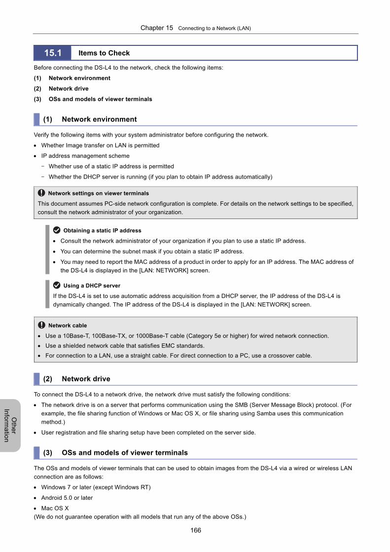
Chapter 15 Connecting to a Network (LAN)
166
Oth
er
Info
rma
tion
15.1 Items to Check
Before connecting the DS-L4 to the network, check the following items:
(1) Network environment
(2) Network drive
(3) OSs and models of viewer terminals
(1) Network environment Verify the following items with your system administrator before configuring the network.
Whether Image transfer on LAN is permitted
IP address management scheme
- Whether use of a static IP address is permitted
- Whether the DHCP server is running (if you plan to obtain IP address automatically)
Network settings on viewer terminals
This document assumes PC-side network configuration is complete. For details on the network settings to be specified,
consult the network administrator of your organization.
Obtaining a static IP address
Consult the network administrator of your organization if you plan to use a static IP address.
You can determine the subnet mask if you obtain a static IP address.
You may need to report the MAC address of a product in order to apply for an IP address. The MAC address of
the DS-L4 is displayed in the [LAN: NETWORK] screen.
Using a DHCP server
If the DS-L4 is set to use automatic address acquisition from a DHCP server, the IP address of the DS-L4 is
dynamically changed. The IP address of the DS-L4 is displayed in the [LAN: NETWORK] screen.
Network cable
Use a 10Base-T, 100Base-TX, or 1000Base-T cable (Category 5e or higher) for wired network connection.
Use a shielded network cable that satisfies EMC standards.
For connection to a LAN, use a straight cable. For direct connection to a PC, use a crossover cable.
(2) Network drive To connect the DS-L4 to a network drive, the network drive must satisfy the following conditions:
The network drive is on a server that performs communication using the SMB (Server Message Block) protocol. (For
example, the file sharing function of Windows or Mac OS X, or file sharing using Samba uses this communication
method.)
User registration and file sharing setup have been completed on the server side.
(3) OSs and models of viewer terminals The OSs and models of viewer terminals that can be used to obtain images from the DS-L4 via a wired or wireless LAN
connection are as follows:
Windows 7 or later (except Windows RT)
Android 5.0 or later
Mac OS X
(We do not guarantee operation with all models that run any of the above OSs.)
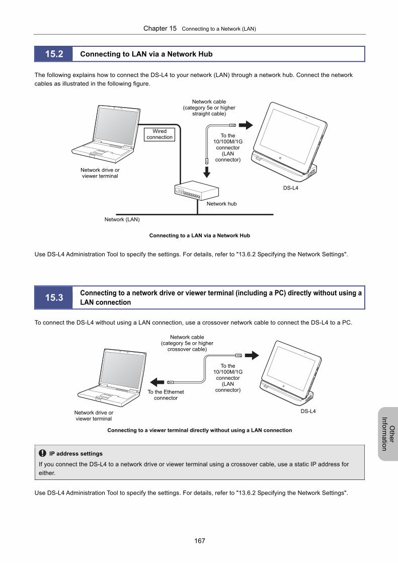
Chapter 15 Connecting to a Network (LAN)
167
Oth
er
Info
rma
tion
15.2 Connecting to LAN via a Network Hub
The following explains how to connect the DS-L4 to your network (LAN) through a network hub. Connect the network
cables as illustrated in the following figure.
Connecting to a LAN via a Network Hub
Use DS-L4 Administration Tool to specify the settings. For details, refer to "13.6.2 Specifying the Network Settings".
15.3 Connecting to a network drive or viewer terminal (including a PC) directly without using a LAN connection
To connect the DS-L4 without using a LAN connection, use a crossover network cable to connect the DS-L4 to a PC.
Connecting to a viewer terminal directly without using a LAN connection
IP address settings
If you connect the DS-L4 to a network drive or viewer terminal using a crossover cable, use a static IP address for
either.
Use DS-L4 Administration Tool to specify the settings. For details, refer to "13.6.2 Specifying the Network Settings".
Network hub
Network (LAN)
Network drive or viewer terminal
Network cable (category 5e or higher
straight cable)
DS-L4
Wired connection To the
10/100M/1G connector
(LAN connector)
Network drive or viewer terminal
Network cable (category 5e or higher
crossover cable)
DS-L4
To the Ethernet connector
To the 10/100M/1G connector
(LAN connector)
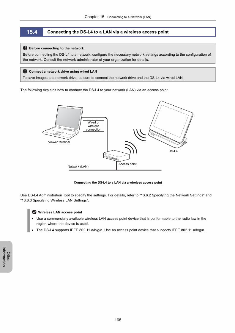
Chapter 15 Connecting to a Network (LAN)
168
Oth
er
Info
rma
tion
15.4 Connecting the DS-L4 to a LAN via a wireless access point
Before connecting to the network
Before connecting the DS-L4 to a network, configure the necessary network settings according to the configuration of
the network. Consult the network administrator of your organization for details.
Connect a network drive using wired LAN
To save images to a network drive, be sure to connect the network drive and the DS-L4 via wired LAN.
The following explains how to connect the DS-L4 to your network (LAN) via an access point.
Connecting the DS-L4 to a LAN via a wireless access point
Use DS-L4 Administration Tool to specify the settings. For details, refer to "13.6.2 Specifying the Network Settings" and
"13.6.3 Specifying Wireless LAN Settings".
Wireless LAN access point
Use a commercially available wireless LAN access point device that is conformable to the radio law in the
region where the device is used.
The DS-L4 supports IEEE 802.11 a/b/g/n. Use an access point device that supports IEEE 802.11 a/b/g/n.
Access point Network (LAN)
Viewer terminal
DS-L4
Wired or wireless
connection
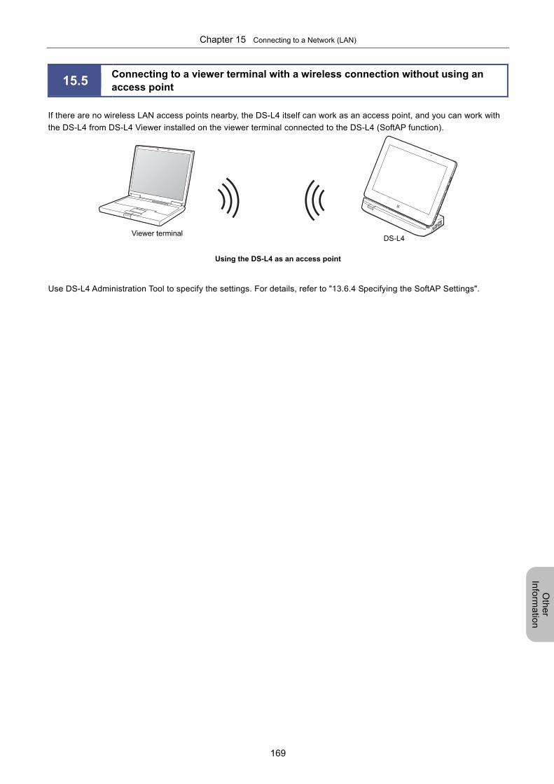
Chapter 15 Connecting to a Network (LAN)
169
Oth
er
Info
rma
tion
15.5 Connecting to a viewer terminal with a wireless connection without using an access point
If there are no wireless LAN access points nearby, the DS-L4 itself can work as an access point, and you can work with
the DS-L4 from DS-L4 Viewer installed on the viewer terminal connected to the DS-L4 (SoftAP function).
Using the DS-L4 as an access point
Use DS-L4 Administration Tool to specify the settings. For details, refer to "13.6.4 Specifying the SoftAP Settings".
Viewer terminalDS-L4
Chapter 15 Connecting to a Network (LAN)
170
Oth
er
Info
rma
tion
15.6 Specifying the file sharing settings on the external information terminal side
To save images from the DS-L4 to an external information terminal, the file sharing settings must be specified on that
terminal. The DS-L4 treats a shared folder as a network drive.
This document describes only basic settings. For details on how to specify the settings, refer to the Help or other
documentation for the OS.
Connect a network drive using wired LAN
To save images to a network drive, be sure to connect the network drive and the DS-L4 via wired LAN.
Note on using SoftAP mode
In SoftAP mode, you cannot save images from the DS-L4 to network drives.
(1) In Windows
Enabling the file sharing function
1 In the Control Panel, click [Choose homegroup and sharing options].
2 Click [Change advanced sharing settings], and then specify the detailed settings.
Select [Turn on network discovery].
Select [Turn on file and printer sharing].
Select [Turn on password protected sharing]. (This item may not be displayed in some environments.)
3 Save the changes to the settings.
Adding a user
Create a new user account.
1 In [Control Panel], open [Administrative Tools], and then open [Computer Management].
2 In the tree view, select [Computer Management (Local)], [System Tools], and then [Local Users and Groups].
3 Right-click [Users], and then select [New User].
4 Enter a user name and password.
Enter a user name of no more than 20 characters, and a password of no more than 127 characters. (For a password,
enter at least one character. If you enter nothing for a password, you cannot access the DS-L4.)
Clear the [User must change password at next logon] checkbox.
Set the image storage folder to be shared
1 Create a folder.
2 Right-click the folder, select [Share with], and then select [Specific people].
3 Click the blank box, and then select the account of the user you created.
If you select [Everyone], the folder can be accessed by all users who can access the external information terminal.
4 Change the access permission level of the user to [Read/Write].
5 Click [Share].
6 Confirm the name of the shared folder, and then click [Done].
Chapter 15 Connecting to a Network (LAN)
171
Oth
er
Info
rma
tion
(2) In Mac OS X
Enabling the file sharing function
1 In the [System Preferences] window, click [Sharing].
2 Select the [File Sharing] checkbox.
3 Closes the window.
Adding a user
1 In the [System Preferences] window, click [Accounts].
2 In the [Accounts] window, click the [+] (add) button, and then set the user ID and password.
3 Close the [Accounts] window.
Set the image storage folder to be shared
1 In [Finder], click the [Action] menu, and then click [New Folder] to create a folder.
2 In the [System Preferences] window, click [Sharing].
3 Under the [Shared Folders] box, click [+].
4 In the window that appears, select the folder to be shared, and then click [Add].
5 Click [Options], and then specify the detailed settings.
Select the [Share files and folders using SMB] checkbox.
Select the checkbox of the registered account. When the [Authenticate] window appears, enter a password, and then click
[OK].
Click [Done].
6 Change the access permission level of the user to [Read & Write].
7 Close the [Sharing] window.
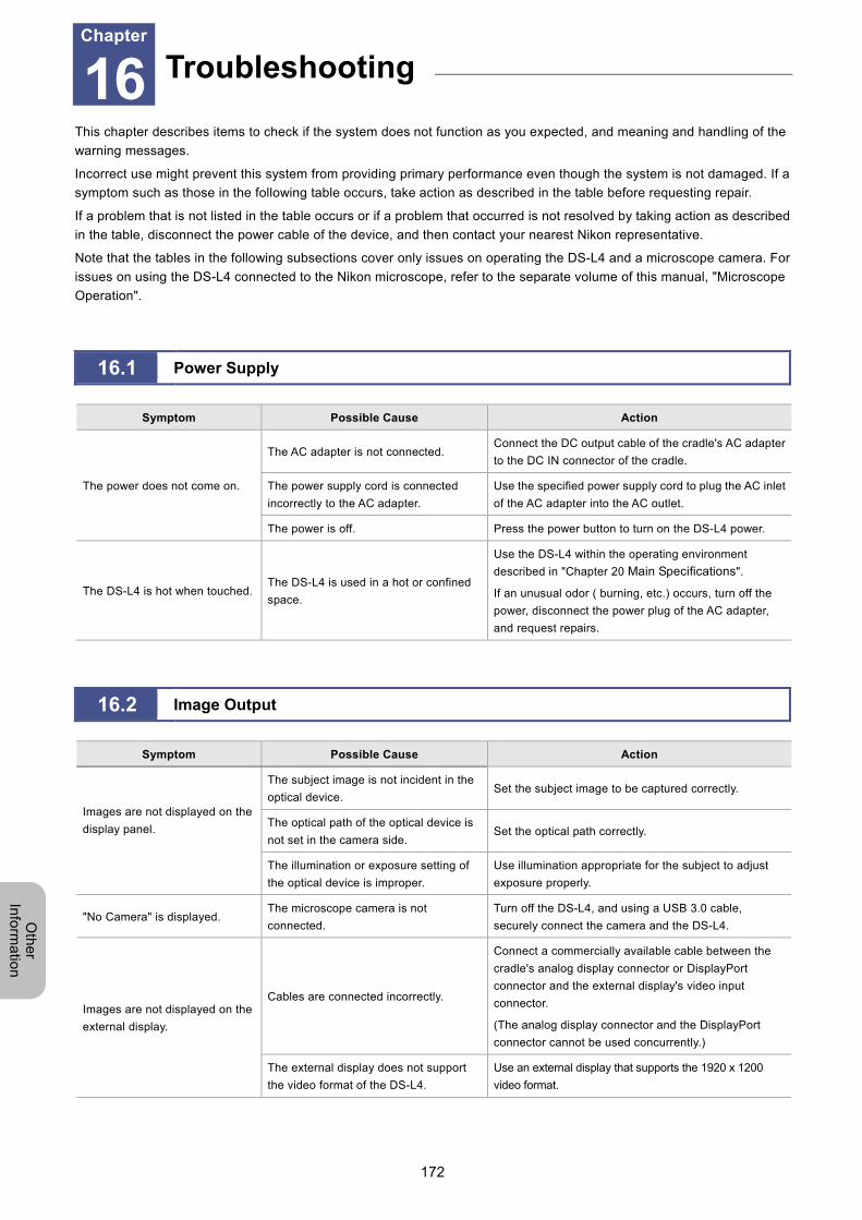
Chapter 16 Troubleshooting
172
Oth
er
Info
rma
tion
16 Troubleshooting
This chapter describes items to check if the system does not function as you expected, and meaning and handling of the
warning messages.
Incorrect use might prevent this system from providing primary performance even though the system is not damaged. If a
symptom such as those in the following table occurs, take action as described in the table before requesting repair.
If a problem that is not listed in the table occurs or if a problem that occurred is not resolved by taking action as described
in the table, disconnect the power cable of the device, and then contact your nearest Nikon representative.
Note that the tables in the following subsections cover only issues on operating the DS-L4 and a microscope camera. For
issues on using the DS-L4 connected to the Nikon microscope, refer to the separate volume of this manual, "Microscope
Operation".
16.1 Power Supply
Symptom Possible Cause Action
The power does not come on.
The AC adapter is not connected. Connect the DC output cable of the cradle's AC adapter
to the DC IN connector of the cradle.
The power supply cord is connected
incorrectly to the AC adapter.
Use the specified power supply cord to plug the AC inlet
of the AC adapter into the AC outlet.
The power is off. Press the power button to turn on the DS-L4 power.
The DS-L4 is hot when touched. The DS-L4 is used in a hot or confined
space.
Use the DS-L4 within the operating environment
described in "Chapter 20 Main Specifications".
If an unusual odor ( burning, etc.) occurs, turn off the
power, disconnect the power plug of the AC adapter,
and request repairs.
16.2 Image Output
Symptom Possible Cause Action
Images are not displayed on the
display panel.
The subject image is not incident in the
optical device. Set the subject image to be captured correctly.
The optical path of the optical device is
not set in the camera side. Set the optical path correctly.
The illumination or exposure setting of
the optical device is improper.
Use illumination appropriate for the subject to adjust
exposure properly.
"No Camera" is displayed. The microscope camera is not
connected.
Turn off the DS-L4, and using a USB 3.0 cable,
securely connect the camera and the DS-L4.
Images are not displayed on the
external display.
Cables are connected incorrectly.
Connect a commercially available cable between the
cradle's analog display connector or DisplayPort
connector and the external display's video input
connector.
(The analog display connector and the DisplayPort
connector cannot be used concurrently.)
The external display does not support
the video format of the DS-L4.
Use an external display that supports the 1920 x 1200
video format.
Troubleshooting Chapter
16
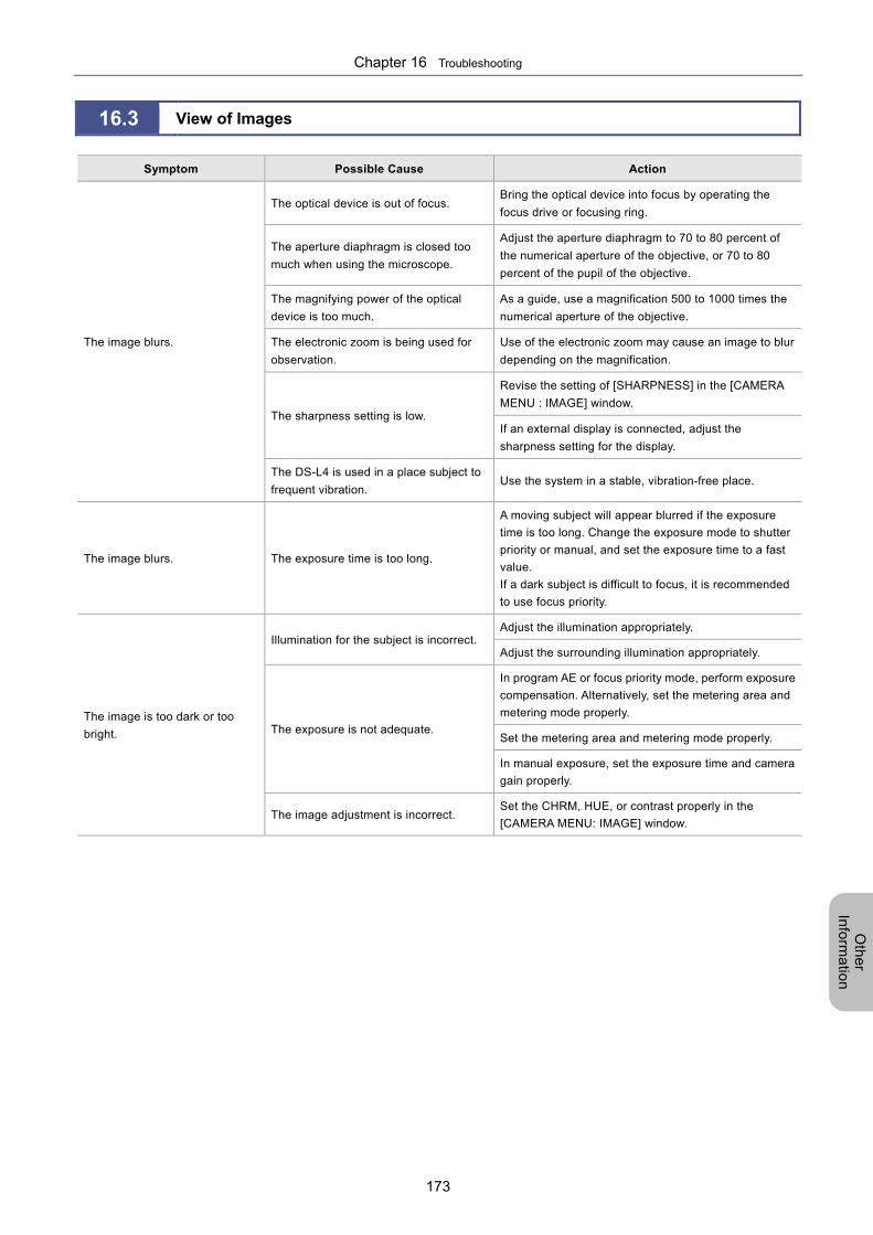
Chapter 16 Troubleshooting
173
Oth
er
Info
rma
tion
16.3 View of Images
Symptom Possible Cause Action
The image blurs.
The optical device is out of focus. Bring the optical device into focus by operating the
focus drive or focusing ring.
The aperture diaphragm is closed too
much when using the microscope.
Adjust the aperture diaphragm to 70 to 80 percent of
the numerical aperture of the objective, or 70 to 80
percent of the pupil of the objective.
The magnifying power of the optical
device is too much.
As a guide, use a magnification 500 to 1000 times the
numerical aperture of the objective.
The electronic zoom is being used for
observation.
Use of the electronic zoom may cause an image to blur
depending on the magnification.
The sharpness setting is low.
Revise the setting of [SHARPNESS] in the [CAMERA
MENU : IMAGE] window.
If an external display is connected, adjust the
sharpness setting for the display.
The DS-L4 is used in a place subject to
frequent vibration. Use the system in a stable, vibration-free place.
The image blurs. The exposure time is too long.
A moving subject will appear blurred if the exposure
time is too long. Change the exposure mode to shutter
priority or manual, and set the exposure time to a fast
value.
If a dark subject is difficult to focus, it is recommended
to use focus priority.
The image is too dark or too
bright.
Illumination for the subject is incorrect. Adjust the illumination appropriately.
Adjust the surrounding illumination appropriately.
The exposure is not adequate.
In program AE or focus priority mode, perform exposure
compensation. Alternatively, set the metering area and
metering mode properly.
Set the metering area and metering mode properly.
In manual exposure, set the exposure time and camera
gain properly.
The image adjustment is incorrect. Set the CHRM, HUE, or contrast properly in the
[CAMERA MENU: IMAGE] window.
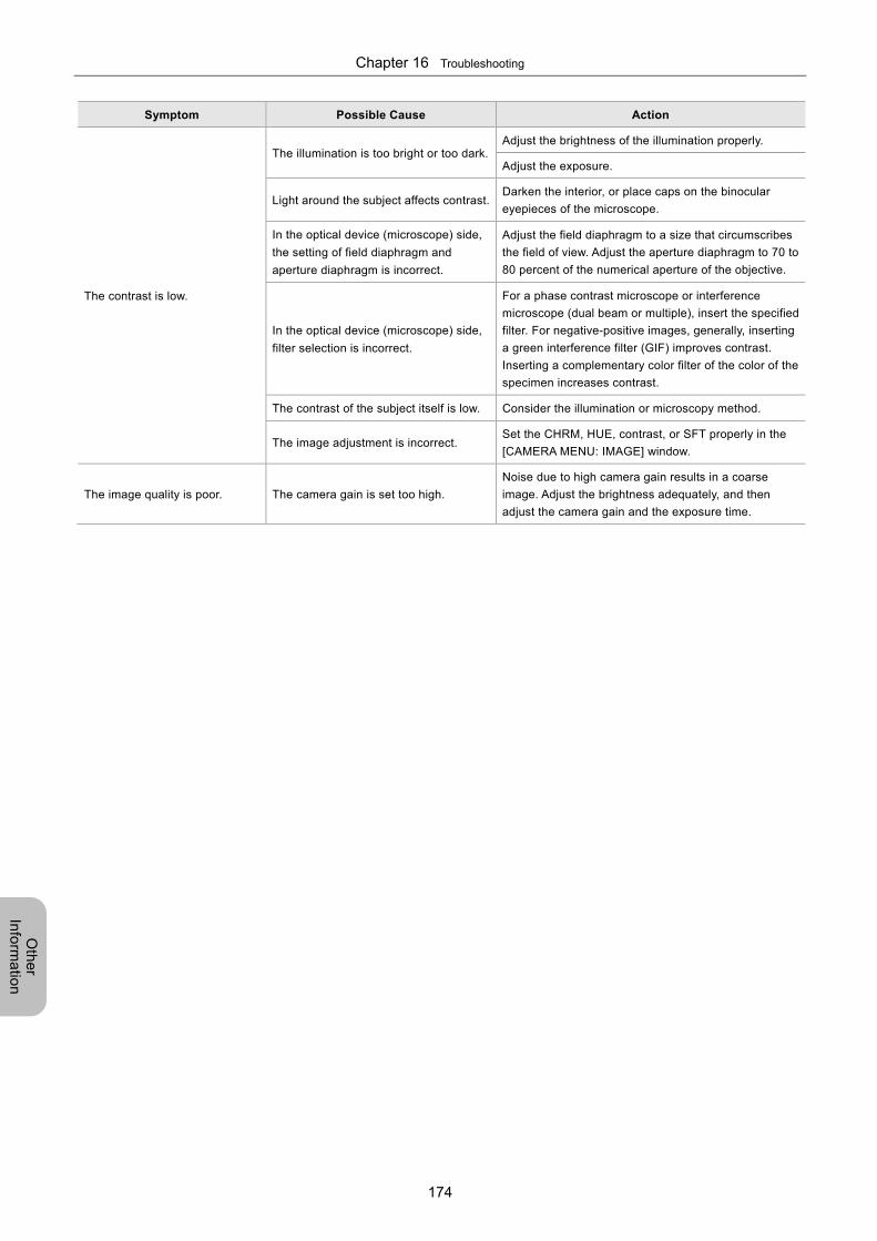
Chapter 16 Troubleshooting
174
Oth
er
Info
rma
tion
Symptom Possible Cause Action
The contrast is low.
The illumination is too bright or too dark.Adjust the brightness of the illumination properly.
Adjust the exposure.
Light around the subject affects contrast.Darken the interior, or place caps on the binocular
eyepieces of the microscope.
In the optical device (microscope) side,
the setting of field diaphragm and
aperture diaphragm is incorrect.
Adjust the field diaphragm to a size that circumscribes
the field of view. Adjust the aperture diaphragm to 70 to
80 percent of the numerical aperture of the objective.
In the optical device (microscope) side,
filter selection is incorrect.
For a phase contrast microscope or interference
microscope (dual beam or multiple), insert the specified
filter. For negative-positive images, generally, inserting
a green interference filter (GIF) improves contrast.
Inserting a complementary color filter of the color of the
specimen increases contrast.
The contrast of the subject itself is low. Consider the illumination or microscopy method.
The image adjustment is incorrect. Set the CHRM, HUE, contrast, or SFT properly in the
[CAMERA MENU: IMAGE] window.
The image quality is poor. The camera gain is set too high.
Noise due to high camera gain results in a coarse
image. Adjust the brightness adequately, and then
adjust the camera gain and the exposure time.
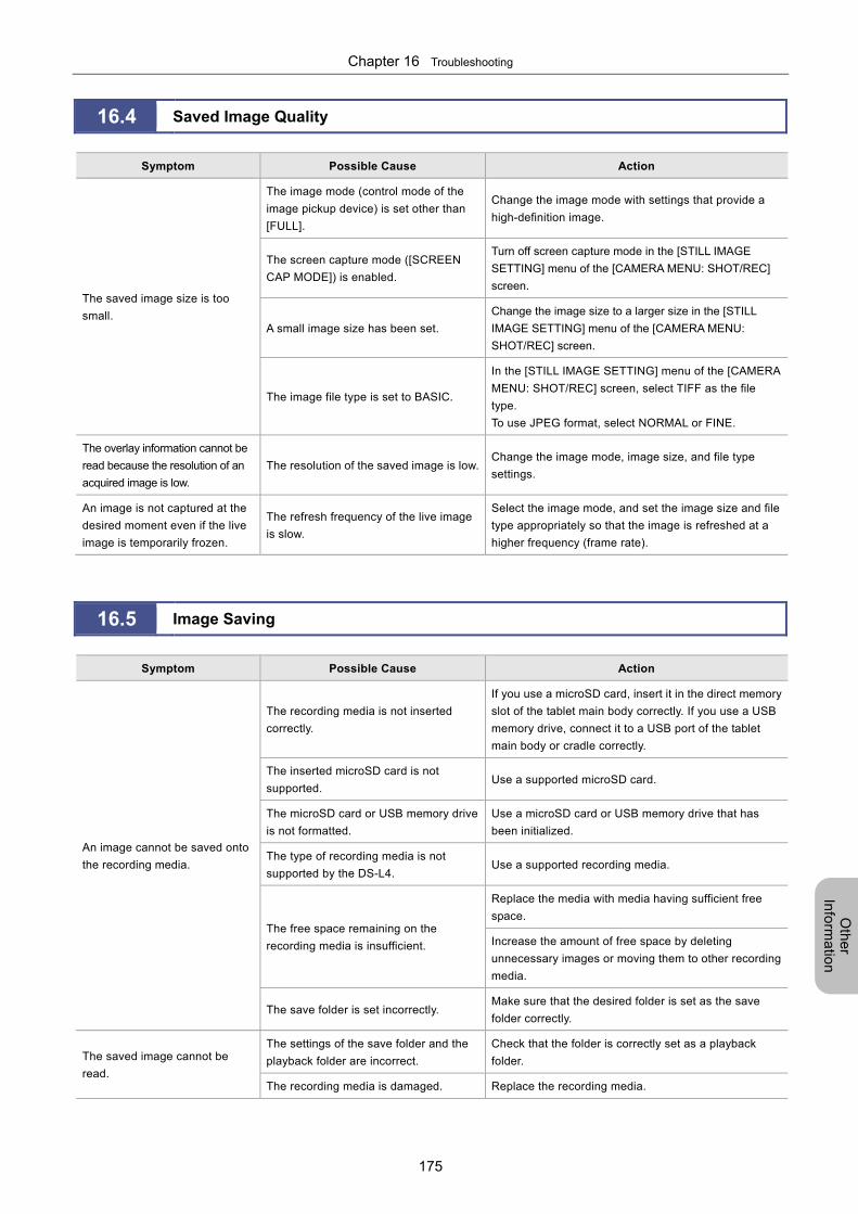
Chapter 16 Troubleshooting
175
Oth
er
Info
rma
tion
16.4 Saved Image Quality
Symptom Possible Cause Action
The saved image size is too
small.
The image mode (control mode of the
image pickup device) is set other than
[FULL].
Change the image mode with settings that provide a
high-definition image.
The screen capture mode ([SCREEN
CAP MODE]) is enabled.
Turn off screen capture mode in the [STILL IMAGE
SETTING] menu of the [CAMERA MENU: SHOT/REC]
screen.
A small image size has been set.
Change the image size to a larger size in the [STILL
IMAGE SETTING] menu of the [CAMERA MENU:
SHOT/REC] screen.
The image file type is set to BASIC.
In the [STILL IMAGE SETTING] menu of the [CAMERA
MENU: SHOT/REC] screen, select TIFF as the file
type.
To use JPEG format, select NORMAL or FINE.
The overlay information cannot be
read because the resolution of an
acquired image is low.
The resolution of the saved image is low.Change the image mode, image size, and file type
settings.
An image is not captured at the
desired moment even if the live
image is temporarily frozen.
The refresh frequency of the live image
is slow.
Select the image mode, and set the image size and file
type appropriately so that the image is refreshed at a
higher frequency (frame rate).
16.5 Image Saving
Symptom Possible Cause Action
An image cannot be saved onto
the recording media.
The recording media is not inserted
correctly.
If you use a microSD card, insert it in the direct memory
slot of the tablet main body correctly. If you use a USB
memory drive, connect it to a USB port of the tablet
main body or cradle correctly.
The inserted microSD card is not
supported. Use a supported microSD card.
The microSD card or USB memory drive
is not formatted.
Use a microSD card or USB memory drive that has
been initialized.
The type of recording media is not
supported by the DS-L4. Use a supported recording media.
The free space remaining on the
recording media is insufficient.
Replace the media with media having sufficient free
space.
Increase the amount of free space by deleting
unnecessary images or moving them to other recording
media.
The save folder is set incorrectly. Make sure that the desired folder is set as the save
folder correctly.
The saved image cannot be
read.
The settings of the save folder and the
playback folder are incorrect.
Check that the folder is correctly set as a playback
folder.
The recording media is damaged. Replace the recording media.
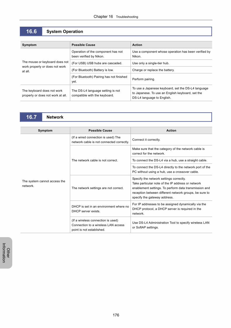
Chapter 16 Troubleshooting
176
Oth
er
Info
rma
tion
16.6 System Operation
Symptom Possible Cause Action
The mouse or keyboard does not
work properly or does not work
at all.
Operation of the component has not
been verified by Nikon.
Use a component whose operation has been verified by
Nikon.
(For USB) USB hubs are cascaded. Use only a single-tier hub.
(For Bluetooth) Battery is low. Charge or replace the battery.
(For Bluetooth) Pairing has not finished
yet. Perform pairing.
The keyboard does not work
properly or does not work at all.
The DS-L4 language setting is not
compatible with the keyboard.
To use a Japanese keyboard, set the DS-L4 language
to Japanese. To use an English keyboard, set the
DS-L4 language to English.
16.7 Network
Symptom Possible Cause Action
The system cannot access the
network.
(If a wired connection is used) The
network cable is not connected correctly.Connect it correctly.
The network cable is not correct.
Make sure that the category of the network cable is
correct for the network.
To connect the DS-L4 via a hub, use a straight cable.
To connect the DS-L4 directly to the network port of the
PC without using a hub, use a crossover cable.
The network settings are not correct.
Specify the network settings correctly.
Take particular note of the IP address or network
enablement settings. To perform data transmission and
reception between different network groups, be sure to
specify the gateway address.
DHCP is set in an environment where no
DHCP server exists.
For IP addresses to be assigned dynamically via the
DHCP protocol, a DHCP server is required in the
network.
(If a wireless connection is used)
Connection to a wireless LAN access
point is not established.
Use DS-L4 Administration Tool to specify wireless LAN
or SoftAP settings.
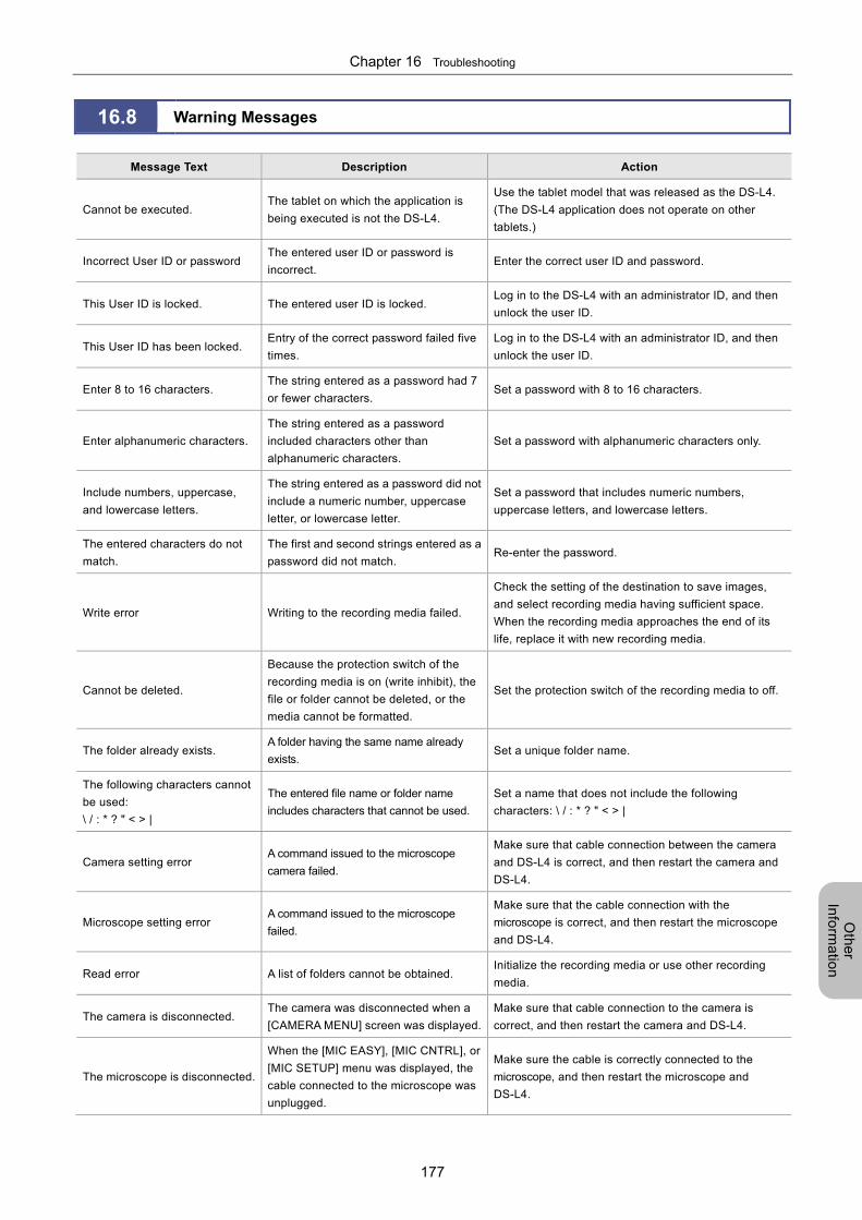
Chapter 16 Troubleshooting
177
Oth
er
Info
rma
tion
16.8 Warning Messages
Message Text Description Action
Cannot be executed. The tablet on which the application is
being executed is not the DS-L4.
Use the tablet model that was released as the DS-L4.
(The DS-L4 application does not operate on other
tablets.)
Incorrect User ID or password The entered user ID or password is
incorrect. Enter the correct user ID and password.
This User ID is locked. The entered user ID is locked. Log in to the DS-L4 with an administrator ID, and then
unlock the user ID.
This User ID has been locked. Entry of the correct password failed five
times.
Log in to the DS-L4 with an administrator ID, and then
unlock the user ID.
Enter 8 to 16 characters. The string entered as a password had 7
or fewer characters. Set a password with 8 to 16 characters.
Enter alphanumeric characters.
The string entered as a password
included characters other than
alphanumeric characters.
Set a password with alphanumeric characters only.
Include numbers, uppercase,
and lowercase letters.
The string entered as a password did not
include a numeric number, uppercase
letter, or lowercase letter.
Set a password that includes numeric numbers,
uppercase letters, and lowercase letters.
The entered characters do not
match.
The first and second strings entered as a
password did not match. Re-enter the password.
Write error Writing to the recording media failed.
Check the setting of the destination to save images,
and select recording media having sufficient space.
When the recording media approaches the end of its
life, replace it with new recording media.
Cannot be deleted.
Because the protection switch of the
recording media is on (write inhibit), the
file or folder cannot be deleted, or the
media cannot be formatted.
Set the protection switch of the recording media to off.
The folder already exists. A folder having the same name already
exists. Set a unique folder name.
The following characters cannot
be used:
\ / : * ? " < > |
The entered file name or folder name
includes characters that cannot be used.
Set a name that does not include the following
characters: \ / : * ? " < > |
Camera setting error A command issued to the microscope
camera failed.
Make sure that cable connection between the camera
and DS-L4 is correct, and then restart the camera and
DS-L4.
Microscope setting error A command issued to the microscope
failed.
Make sure that the cable connection with the
microscope is correct, and then restart the microscope
and DS-L4.
Read error A list of folders cannot be obtained. Initialize the recording media or use other recording
media.
The camera is disconnected. The camera was disconnected when a
[CAMERA MENU] screen was displayed.
Make sure that cable connection to the camera is
correct, and then restart the camera and DS-L4.
The microscope is disconnected.
When the [MIC EASY], [MIC CNTRL], or
[MIC SETUP] menu was displayed, the
cable connected to the microscope was
unplugged.
Make sure the cable is correctly connected to the
microscope, and then restart the microscope and
DS-L4.
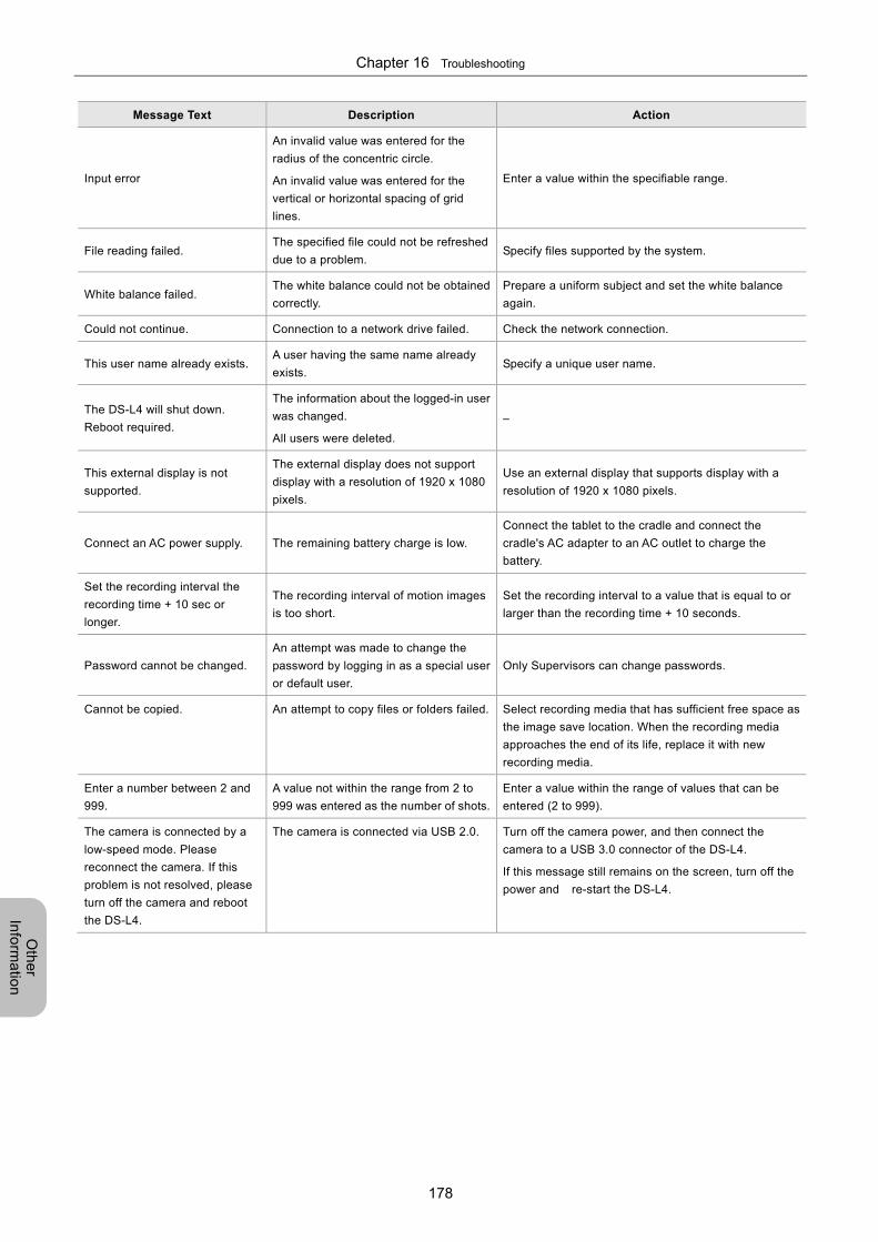
Chapter 16 Troubleshooting
178
Oth
er
Info
rma
tion
Message Text Description Action
Input error
An invalid value was entered for the
radius of the concentric circle.
An invalid value was entered for the
vertical or horizontal spacing of grid
lines.
Enter a value within the specifiable range.
File reading failed. The specified file could not be refreshed
due to a problem. Specify files supported by the system.
White balance failed. The white balance could not be obtained
correctly.
Prepare a uniform subject and set the white balance
again.
Could not continue. Connection to a network drive failed. Check the network connection.
This user name already exists. A user having the same name already
exists. Specify a unique user name.
The DS-L4 will shut down.
Reboot required.
The information about the logged-in user
was changed.
All users were deleted.
–
This external display is not
supported.
The external display does not support
display with a resolution of 1920 x 1080
pixels.
Use an external display that supports display with a
resolution of 1920 x 1080 pixels.
Connect an AC power supply. The remaining battery charge is low.
Connect the tablet to the cradle and connect the
cradle's AC adapter to an AC outlet to charge the
battery.
Set the recording interval the
recording time + 10 sec or
longer.
The recording interval of motion images
is too short.
Set the recording interval to a value that is equal to or
larger than the recording time + 10 seconds.
Password cannot be changed.
An attempt was made to change the
password by logging in as a special user
or default user.
Only Supervisors can change passwords.
Cannot be copied. An attempt to copy files or folders failed. Select recording media that has sufficient free space as
the image save location. When the recording media
approaches the end of its life, replace it with new
recording media.
Enter a number between 2 and
999.
A value not within the range from 2 to
999 was entered as the number of shots.
Enter a value within the range of values that can be
entered (2 to 999).
The camera is connected by a
low-speed mode. Please
reconnect the camera. If this
problem is not resolved, please
turn off the camera and reboot
the DS-L4.
The camera is connected via USB 2.0. Turn off the camera power, and then connect the
camera to a USB 3.0 connector of the DS-L4.
If this message still remains on the screen, turn off the
power and re-start the DS-L4.
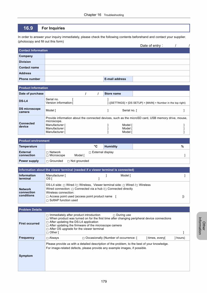
Chapter 16 Troubleshooting
179
Oth
er
Info
rma
tion
16.9 For Inquiries In order to answer your inquiry immediately, please check the following contents beforehand and contact your supplier.
(photocopy and fill out this form) Date of entry: / /
Contact Information
Company
Division
Contact name
Address
Phone number E-mail address
Product Information
Date of purchase / / Store name
DS-L4 Serial no. [ ] Version information [ ] ([SETTINGS] > [DS SETUP] > [MAIN] > Number in the top right)
DS microscope camera Model [ ] Serial no. [ ]
Connected device
Provide information about the connected devices, such as the microSD card, USB memory drive, mouse, microscope. Manufacturer [ ] Model [ ] Manufacturer [ ] Model [ ] Manufacturer [ ] Model [ ]
Product environment
Temperature °C Humidity %
External connection
□ Network □ External display □ Microscope Model [ ]
Power supply □ Grounded □ Not grounded
Information about the viewer terminal (needed if a viewer terminal is connected)
Information terminal
Manufacturer [ ] Model [ ] OS [ ]
Network connection conditions
DS-L4 side: □ Wired /□ Wireless, Viewer terminal side: □ Wired /□ Wireless Wired connection: □ Connected via a hub /□ Connected directly Wireless connection:
□ Access point used (access point product name [ ])
□ SoftAP function used
Problem Details
First occurred
□ Immediately after product introduction □ During use □ When product was turned on for the first time after changing peripheral device connections □ After updating the DS-L4 application □ After updating the firmware of the microscope camera □ After OS upgrade for the viewer terminal □ Other [ ]
Frequency □ Always □ Occasionally (Number of occurrence: [ ] times, every[ ] hours)
Symptom
Please provide us with a detailed description of the problem, to the best of your knowledge.
For image-related defects, please provide any example images, if possible.
Chapter 17 Using the Diagnostic Program
180
Oth
er
Info
rma
tion
17 Performing Captures from an External Device
In addition to tapping the [CAPTURE] button on the DS-L4 screen, you can capture still images with the DS-L4 by using
one of the following three methods:
Sending a communication command from the USB connector of the microscope (available with the Ni-E and Ni-U only).
For details, refer to the separate volume of this manual, "Microscope Operation". Note that this method cannot be used
if the microscope is set to output trigger signals from the DSC connector.
Connecting an external device (external capture output device) to the camera's EXT I/O connector, inputting a signal
from the external device to the camera, and sending a communication command from the camera to the DS-L4. For
details, refer to the manual of the camera.
Clicking the center or right button of the mouse connected to the DS-L4. The necessary settings must be specified
beforehand ([SETTINGS] > [DS SETUP] > [MAIN]).
Notes on performing captures from an external device
Consecutive capture cannot be performed from an external device. Even if [CONT.] is selected as the shot
mode from the [STILL IMAGE SETTING] menu of the [CAMERA MENU: SHOT/REC] screen, single shot mode
is enabled.
Capture is not possible in the following cases: when no camera is connected, when thumbnails are displayed,
when the [DS SETUP] menu is displayed, and when the [MIC SETUP] menu is displayed.
Performing Captures from an External Device
Chapter
17
Chapter 17 Using the Diagnostic Program
181
Oth
er
Info
rma
tion
18 Using the Diagnostic Program
The diagnostic program can be executed from the BIOS menu to check whether hardware errors have occurred.
If error codes are displayed after diagnosis, notify your nearest Nikon representative of the error codes.
Notes on executing the diagnostic program
Before you execute the diagnostic program, turn off the DS-L4 power completely. To turn off the DS-L4 power, in the
LIVE or VIEW menu, tap [SETTINGS], and then select [SHUT DOWN].
You need to disconnect peripheral devices before executing the diagnostic program. Disconnect USB memory
drives, external hard disks, and other peripheral devices that are recognized as hard disks or removable disks.
1 Hold down the shortcut button and press the power button of the DS-L4.
Continue to press the shortcut button (for about 10 seconds) until the boot menu appears.
2 When the boot menu appears, release the shortcut button.
3 Tap [Tab] to display the application menu.
4 Tap and select [Diagnostic Program], and then tap it again.
5 Tap [Run].
Hardware diagnosis starts. When hardware diagnosis ends, the results of diagnosis appears.
6 If no problems are detected, tap [Reboot].
The DS-L4 is restarted.
If problems are detected, record the displayed information. Then, press the power button to turn off the tablet
power.
Notify your nearest Nikon representative of the displayed information.
Using the Diagnostic Program Chapter
18
Chapter 18 Daily Maintenance
182
Oth
er
Info
rma
tion
19 Daily Maintenance
This chapter describes how to maintain the DS-L4. To prolong the performance of the DS-L4, Nikon recommends that you
perform daily maintenance.
19.1 Cleaning Utensils and Consumables
Cleaning utensils
Soft cloth (non-woven cloth, cotton cloth, or gauze)*
Lens cloth
* In a cleanroom, use a cleanroom wiper.
Consumables
Neutral detergent (only when the product main body is very dirty)
19.2 Cleaning of the Tablet, Cradle, and Display
To clean the tablet main body or cradle, use a dry soft cloth. If the tablet or cradle is very dirty, use a cloth moistened with
water or diluted neutral detergent. If diluted neutral detergent is used for cleaning, remove any residue with a cloth
moistened with water.
If the display panel surface is dirty, use a dry soft cloth or a lens cloth to wipe off the surface gently, taking care not to
scratch the surface with a nail or ring. Never use water or detergent for cleaning.
Notes on cleaning an LCD display or touch panel
Do not rub or forcibly push on the surface of an LCD display or touch panel. Doing so may damage the LCD display or
touch panel. Some wipes or commercially available cleaners may chemically damage the coating of the surface. Do not
use:
Anything that contains an alkaline component
Anything that contains a surface-activating agent
Anything that contains an alcohol component
Anything that is highly volatile (e.g., thinner or benzine)
Anything that contains abrasives
19.3 Cleaning a Microscope Camera
When you clean the main body of a microscope camera, make sure that the mount is covered with a mount cap, and then
wipe off stains with a soft cloth. If the product is very dirty, gently wipe stains using gauze moistened with a small amount
of diluted neutral detergent.
Do not use organic solvent (such as alcohol, ether, and thinner) on coated parts, plastic parts, or printed parts. Doing so
may cause surface discoloration or removal of printed characters.
Remove any dust inside the camera mount with an air blower.
Cleaning of the inside of a camera
Use only an air blower to remove dust from inside the camera mount, so as to minimize the risk of contact with internal
components. Especially, never touch the glass filter on the front of the image pickup device.
If you have touched the glass filter of the image pickup device, or accumulated dust on the glass filter cannot be
removed, inquire about cleaning to your nearest Nikon representative.
Daily Maintenance Chapter
19
Chapter 19 Daily Maintenance
183
Oth
er
Info
rma
tion
19.4 Cleaning Optical Devices
Prevent dust or fingerprints from being attached to the lenses of the optical device. Stains on a lens degrade the visibility
of images.
For details on how to clean optical devices, see the instructions of your optical device.
19.5 Storage
Turn off the product whenever you do not use it. If you do not intend to use the product for a long period of time, unplug
the power supply cord of the AC adapter.
Store the product in a location satisfying the storage environment conditions described in user guide of ARROWS Tab
Q555/K64.
Store this system in a location with low humidity, where mold is unlikely to form.
When you store a microscope camera, make sure that the mount is covered with a mount cap.
During storage, place a plastic cover over the equipment to prevent dust accumulation. Before putting a plastic cover
on the DS-L4, turn off the DS-L4 power, and wait for the DS-L4 to cool down.
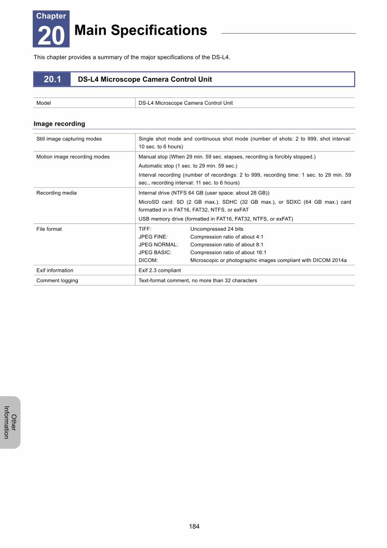
Chapter 20 Main Specifications
184
Oth
er
Info
rma
tion
20 Main Specifications
This chapter provides a summary of the major specifications of the DS-L4.
20.1 DS-L4 Microscope Camera Control Unit
Model DS-L4 Microscope Camera Control Unit
Image recording
Still image capturing modes Single shot mode and continuous shot mode (number of shots: 2 to 999, shot interval:
10 sec. to 6 hours)
Motion image recording modes Manual stop (When 29 min. 59 sec. elapses, recording is forcibly stopped.)
Automatic stop (1 sec. to 29 min. 59 sec.)
Interval recording (number of recordings: 2 to 999, recording time: 1 sec. to 29 min. 59
sec., recording interval: 11 sec. to 6 hours)
Recording media Internal drive (NTFS 64 GB (user space: about 28 GB))
MicroSD card: SD (2 GB max.), SDHC (32 GB max.), or SDXC (64 GB max.) card
formatted in in FAT16, FAT32, NTFS, or exFAT
USB memory drive (formatted in FAT16, FAT32, NTFS, or exFAT)
File format TIFF: Uncompressed 24 bits
JPEG FINE: Compression ratio of about 4:1
JPEG NORMAL: Compression ratio of about 8:1
JPEG BASIC: Compression ratio of about 16:1
DICOM: Microscopic or photographic images compliant with DICOM 2014a
Exif information Exif 2.3 compliant
Comment logging Text-format comment, no more than 32 characters
Main Specifications Chapter
20
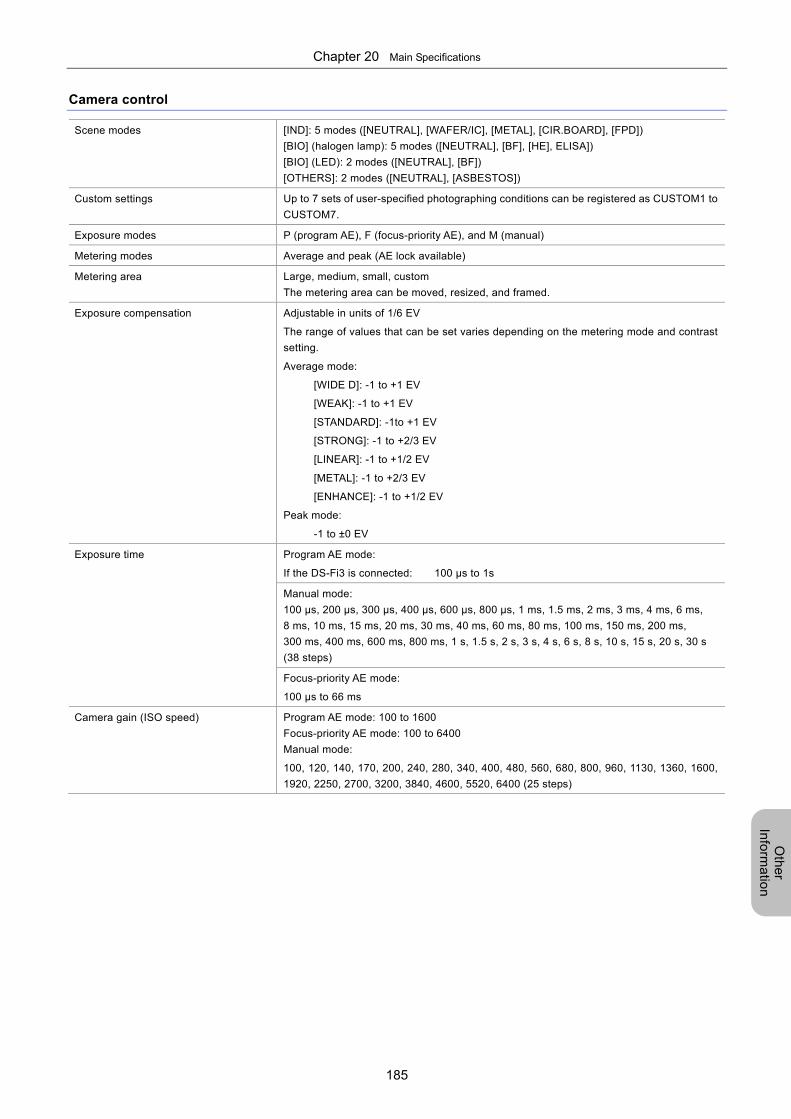
Chapter 20 Main Specifications
185
Oth
er
Info
rma
tion
Camera control
Scene modes [IND]: 5 modes ([NEUTRAL], [WAFER/IC], [METAL], [CIR.BOARD], [FPD])
[BIO] (halogen lamp): 5 modes ([NEUTRAL], [BF], [HE], ELISA])
[BIO] (LED): 2 modes ([NEUTRAL], [BF])
[OTHERS]: 2 modes ([NEUTRAL], [ASBESTOS])
Custom settings Up to 7 sets of user-specified photographing conditions can be registered as CUSTOM1 to
CUSTOM7.
Exposure modes P (program AE), F (focus-priority AE), and M (manual)
Metering modes Average and peak (AE lock available)
Metering area Large, medium, small, custom
The metering area can be moved, resized, and framed.
Exposure compensation Adjustable in units of 1/6 EV
The range of values that can be set varies depending on the metering mode and contrast
setting.
Average mode:
[WIDE D]: -1 to +1 EV
[WEAK]: -1 to +1 EV
[STANDARD]: -1to +1 EV
[STRONG]: -1 to +2/3 EV
[LINEAR]: -1 to +1/2 EV
[METAL]: -1 to +2/3 EV
[ENHANCE]: -1 to +1/2 EV
Peak mode:
-1 to ±0 EV
Exposure time Program AE mode:
If the DS-Fi3 is connected: 100 µs to 1s
Manual mode:
100 µs, 200 µs, 300 µs, 400 µs, 600 µs, 800 µs, 1 ms, 1.5 ms, 2 ms, 3 ms, 4 ms, 6 ms,
8 ms, 10 ms, 15 ms, 20 ms, 30 ms, 40 ms, 60 ms, 80 ms, 100 ms, 150 ms, 200 ms,
300 ms, 400 ms, 600 ms, 800 ms, 1 s, 1.5 s, 2 s, 3 s, 4 s, 6 s, 8 s, 10 s, 15 s, 20 s, 30 s
(38 steps)
Focus-priority AE mode:
100 µs to 66 ms
Camera gain (ISO speed) Program AE mode: 100 to 1600
Focus-priority AE mode: 100 to 6400
Manual mode:
100, 120, 140, 170, 200, 240, 280, 340, 400, 480, 560, 680, 800, 960, 1130, 1360, 1600,
1920, 2250, 2700, 3200, 3840, 4600, 5520, 6400 (25 steps)
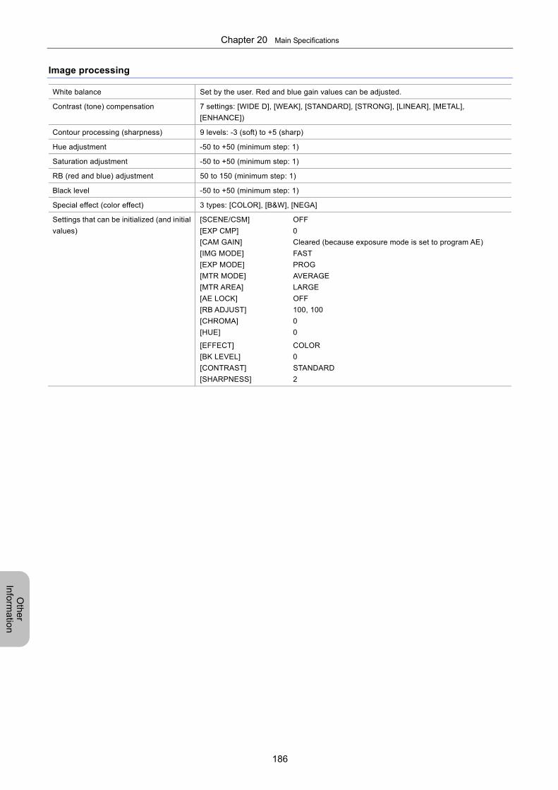
Chapter 20 Main Specifications
186
Oth
er
Info
rma
tion
Image processing
White balance Set by the user. Red and blue gain values can be adjusted.
Contrast (tone) compensation 7 settings: [WIDE D], [WEAK], [STANDARD], [STRONG], [LINEAR], [METAL],
[ENHANCE])
Contour processing (sharpness) 9 levels: -3 (soft) to +5 (sharp)
Hue adjustment -50 to +50 (minimum step: 1)
Saturation adjustment -50 to +50 (minimum step: 1)
RB (red and blue) adjustment 50 to 150 (minimum step: 1)
Black level -50 to +50 (minimum step: 1)
Special effect (color effect) 3 types: [COLOR], [B&W], [NEGA]
Settings that can be initialized (and initial
values)
[SCENE/CSM] OFF
[EXP CMP] 0
[CAM GAIN] Cleared (because exposure mode is set to program AE)
[IMG MODE] FAST
[EXP MODE] PROG
[MTR MODE] AVERAGE
[MTR AREA] LARGE
[AE LOCK] OFF
[RB ADJUST] 100, 100
[CHROMA] 0
[HUE] 0
[EFFECT] COLOR
[BK LEVEL] 0
[CONTRAST] STANDARD
[SHARPNESS] 2
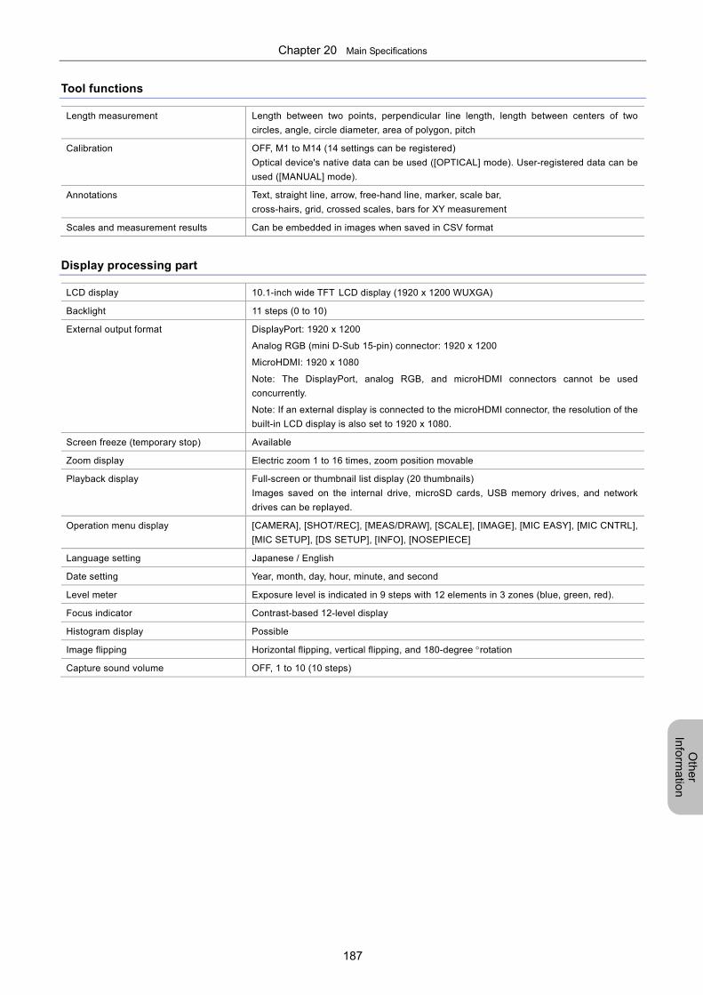
Chapter 20 Main Specifications
187
Oth
er
Info
rma
tion
Tool functions
Length measurement Length between two points, perpendicular line length, length between centers of two
circles, angle, circle diameter, area of polygon, pitch
Calibration OFF, M1 to M14 (14 settings can be registered)
Optical device's native data can be used ([OPTICAL] mode). User-registered data can be
used ([MANUAL] mode).
Annotations Text, straight line, arrow, free-hand line, marker, scale bar,
cross-hairs, grid, crossed scales, bars for XY measurement
Scales and measurement results Can be embedded in images when saved in CSV format
Display processing part
LCD display 10.1-inch wide TFT LCD display (1920 x 1200 WUXGA)
Backlight 11 steps (0 to 10)
External output format DisplayPort: 1920 x 1200
Analog RGB (mini D-Sub 15-pin) connector: 1920 x 1200
MicroHDMI: 1920 x 1080
Note: The DisplayPort, analog RGB, and microHDMI connectors cannot be used
concurrently.
Note: If an external display is connected to the microHDMI connector, the resolution of the
built-in LCD display is also set to 1920 x 1080.
Screen freeze (temporary stop) Available
Zoom display Electric zoom 1 to 16 times, zoom position movable
Playback display Full-screen or thumbnail list display (20 thumbnails)
Images saved on the internal drive, microSD cards, USB memory drives, and network
drives can be replayed.
Operation menu display [CAMERA], [SHOT/REC], [MEAS/DRAW], [SCALE], [IMAGE], [MIC EASY], [MIC CNTRL],
[MIC SETUP], [DS SETUP], [INFO], [NOSEPIECE]
Language setting Japanese / English
Date setting Year, month, day, hour, minute, and second
Level meter Exposure level is indicated in 9 steps with 12 elements in 3 zones (blue, green, red).
Focus indicator Contrast-based 12-level display
Histogram display Possible
Image flipping Horizontal flipping, vertical flipping, and 180-degree rotation
Capture sound volume OFF, 1 to 10 (10 steps)
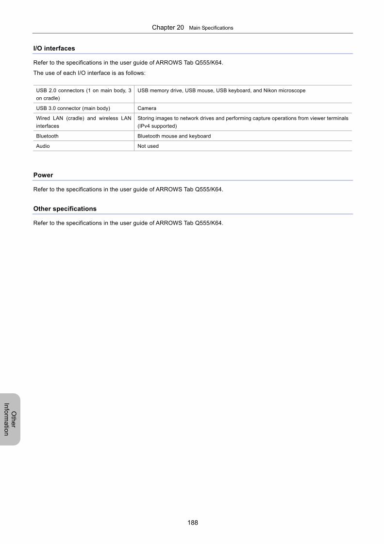
Chapter 20 Main Specifications
188
Oth
er
Info
rma
tion
I/O interfaces
Refer to the specifications in the user guide of ARROWS Tab Q555/K64.
The use of each I/O interface is as follows:
USB 2.0 connectors (1 on main body, 3
on cradle)
USB memory drive, USB mouse, USB keyboard, and Nikon microscope
USB 3.0 connector (main body) Camera
Wired LAN (cradle) and wireless LAN
interfaces
Storing images to network drives and performing capture operations from viewer terminals
(IPv4 supported)
Bluetooth Bluetooth mouse and keyboard
Audio Not used
Power
Refer to the specifications in the user guide of ARROWS Tab Q555/K64.
Other specifications
Refer to the specifications in the user guide of ARROWS Tab Q555/K64.