Embed Size (px)
Citation preview
DS8000Digital stimulator
INSTRUCTION MANUAL
Serial No._____________________
042712
World Precision Instruments
ww
w.w
pii
nc.
com

WORLD PRECISION INSTRUMENTS iii
DS8000
CONTENTS1.0 Introduction ................................................................................................................................................1
2.0 General Warnings and Cautions ..........................................................................................................3
Unpacking ..........................................................................................................................................................4
3.0 Description .................................................................................................................................................5
3.1 General .......................................................................................................................................................5
3.2 Microcontroller .........................................................................................................................................5
3.3 Communications ......................................................................................................................................5
3.4 Digital Control & Digital Signal Processing (DSP) ............................................................................5
3.5 Analog Outputs .........................................................................................................................................6
3.7 Rear Panel Connections .........................................................................................................................7
3.8 Block Diagram ..........................................................................................................................................9
4.0 Installation .............................................................................................................................................. 10
4.1 Mechanical ............................................................................................................................................. 10
4.2 Electrical .................................................................................................................................................. 10
4.3 Network ................................................................................................................................................... 10
4.4 Quick Start Operation .......................................................................................................................... 10
5.0 Operation ................................................................................................................................................ 14
5.1 General Parameters .............................................................................................................................. 14
5.2 Channel Screen ...................................................................................................................................... 14
5.3 Trigger and Mode Screen Detail ....................................................................................................... 16
5.4 Train Screen Detail ................................................................................................................................ 17
5.5 Paired Pulse Modes Overview ........................................................................................................... 19
5.6 Paired Mode Screen Detail ................................................................................................................. 20
5.7 T-Paired Mode Screen Detail .............................................................................................................. 22
5.8 Waveform Screen Detail ..................................................................................................................... 24
5.9 Timer Screen .......................................................................................................................................... 26
5.10 Run Screen ........................................................................................................................................... 27
5.11 Combined Analog Screen ................................................................................................................. 27
DS8000
WORLD PRECISION INSTRUMENTSiv
5.12 Combined TTL Screen ....................................................................................................................... 28
5.13 Scope Screen ....................................................................................................................................... 28
5.14 Settings Screen .................................................................................................................................... 29
5.15 General Screen .................................................................................................................................... 30
5.16 GUI Screen ........................................................................................................................................... 31
5.17 Memory Screen ................................................................................................................................... 33
5.18 Profile Screen ....................................................................................................................................... 33
5.19 Communication Screen .................................................................................................................... 34
5.20 FTP Screen ............................................................................................................................................ 34
5.21 About Screen ....................................................................................................................................... 35
6.0 Serial & Network Communication .................................................................................................... 36
6.1 Network Hardware Setup .................................................................................................................... 36
6.2 Serial and Network Control ................................................................................................................ 38
6.3 Custom Waveform Via the Custom Table Loader Program ........................................................ 47
6.4 Custom Waveform Via the Excel® Macro ...................................................................................... 49
7.0 Maintenance ........................................................................................................................................... 52
7.1 Cleaning Instructions ............................................................................................................................ 52
7.2 Scratch Prevention ................................................................................................................................ 52
8.0 Troubleshooting ..................................................................................................................................... 53
Replacing the fuse ........................................................................................................................................ 53
FTP Error Codes ............................................................................................................................................. 53
9.0 Technical Specifications ...................................................................................................................... 54
9.1 General Specifications ......................................................................................................................... 54
9.2 Software ................................................................................................................................................... 55
10.0 Appendix 1: Stimulus Isolator Applications Cookbook ............................................................ 57
11.0 Appendix 2: Example Bioresearch Applications ......................................................................... 61
Warranty ......................................................................................................................................................... 63
Copyright © 2012 by World Precision Instruments, Inc. All rights reserved. No part of this publication may be
reproduced or translated into any language, in any form, without prior written permission of World Precision
Instruments, Inc.
WORLD PRECISION INSTRUMENTS 1
DS8000
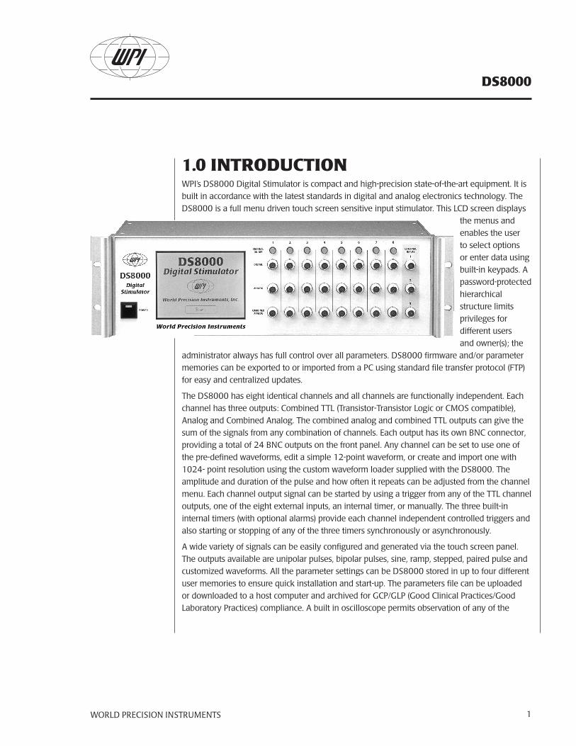
1.0 INTRODUCTIONWPI’s DS8000 Digital Stimulator is compact and high-precision state-of-the-art equipment. It is built in accordance with the latest standards in digital and analog electronics technology. The DS8000 is a full menu driven touch screen sensitive input stimulator. This LCD screen displays
the menus and enables the user to select options or enter data using built-in keypads. A password-protected hierarchical structure limits privileges for different users and owner(s); the
administrator always has full control over all parameters. DS8000 firmware and/or parameter memories can be exported to or imported from a PC using standard file transfer protocol (FTP) for easy and centralized updates.
The DS8000 has eight identical channels and all channels are functionally independent. Each channel has three outputs: Combined TTL (Transistor-Transistor Logic or CMOS compatible), Analog and Combined Analog. The combined analog and combined TTL outputs can give the sum of the signals from any combination of channels. Each output has its own BNC connector, providing a total of 24 BNC outputs on the front panel. Any channel can be set to use one of the pre-defined waveforms, edit a simple 12-point waveform, or create and import one with 1024- point resolution using the custom waveform loader supplied with the DS8000. The amplitude and duration of the pulse and how often it repeats can be adjusted from the channel menu. Each channel output signal can be started by using a trigger from any of the TTL channel outputs, one of the eight external inputs, an internal timer, or manually. The three built-in internal timers (with optional alarms) provide each channel independent controlled triggers and also starting or stopping of any of the three timers synchronously or asynchronously.
A wide variety of signals can be easily configured and generated via the touch screen panel. The outputs available are unipolar pulses, bipolar pulses, sine, ramp, stepped, paired pulse and customized waveforms. All the parameter settings can be DS8000 stored in up to four different user memories to ensure quick installation and start-up. The parameters file can be uploaded or downloaded to a host computer and archived for GCP/GLP (Good Clinical Practices/Good Laboratory Practices) compliance. A built in oscilloscope permits observation of any of the
DS8000
WORLD PRECISION INSTRUMENTS2
signals generated by the DS8000. It displays two channels simultaneously and can be triggered by any of the internal signals or by one of the external inputs.
The DS8000 is a highly advanced technical instrument with numerous functions and operating modes. Some users may find that the Quick Start procedure is sufficient for their understanding and other features will become familiar with hands-on experience at using the various on-screen menus.
The manual may be routinely revised to take account of any software upgrades. In the meantime, if you need assistance with the DS8000 we would appreciate your call (tel.: 941-371-1003, or email the Technical Specialist directly at [email protected]).
WORLD PRECISION INSTRUMENTS 3
DS8000
2.0 GENERAL WARNINGS AND CAUTIONSWARNING: THE DS8000 DIGITAL STIMULATOR MUST ONLY BE USED IN A DRY ROOM.
WARNING: THE DS8000 DIGITAL STIMULATOR MUST ALWAYS BE GROUNDED.
WARNING: DO NOT CONNECT ANY INPUT/OUTPUT TERMINAL TO
THE MAINS SUPPLY, UNLESS THROUGH AN ISOLATION CIRCUIT.
CAUTION: Exercise care in using the touch-sensitive LCD screen. It is designed for finger-pressure only. DO NOT touch with pen, pencil, or any sharp object. THE LCD SCREEN IS NOT COVERED UNDER THE INSTRUMENT WARRANTY.
CAUTION: The Digital Stimulator output defaults on start-up in the off condition. Outputs are unstable during power initialization. Please ensure proper sequencing of power up and connections to avoid unwanted stimulation to the subject.
CAUTION: The maximum input voltages must not be exceeded. CAUTION: Repairs of an electrical or mechanical nature may only be carried out by an authorized WPI technician.
NOTE: WPI reserves the right to adapt the equipment to the latest technical specifications at any time.
Restrictions: This device may not be used for clinical treatment of humans.
DS8000
WORLD PRECISION INSTRUMENTS4
UnpackingThe DS8000 Packing list is as follows:
• Instruction Manual (this document)
• Quick Start card (Section 4 of the manual)
• 6-foot (2m) BNC cables WPI P/N 2851 (four)
• 90 degree BNC adaptors WPI P/N 500256 (four)
• 9-pin Serial cable WPI P/N 13555
• Network crossover cable (for stand alone networking only)
• Power cord (3006 US, 3301 EURO, 3302 UK, or 14088 AUS)
• Standard stylus
• Spare touch screen protective cover
• Touch screen warning label
• CD-ROM containing: (for GLP/ GCP archiving purposes)
Instruction Manual in PDF format
Quick Start Card in PDF format
Latest firmware version for DS8000
FTP shareware program
Excel macro based custom waveform loader and additional installation files (if needed) (Office 2000 use only)
Stand alone executable custom waveform loader CTG 0.1.0.exe
WORLD PRECISION INSTRUMENTS 5
DS8000
3.0 DESCRIPTION
3.1 GeneralThe DS8000 Digital Stimulator is an 8-channel stimulator intended to control a wide range of stimulus isolation units. All of these parameters (duration, amplitude, interpulse intervals, delay) can be independently set for each channel.
The analog signals are real-time converted digital values (24-bit resolution) and processed by a DSP. After processing, the digital signals are real-time converted to analog signals and applied to the output sockets. The output signal of each channel is available at a front panel connector and can also be viewed on the graphical display.
The DS8000 is full menu driven. The touch screen LCD shows the menus and enablesthe operator to select or enter data. A password protected hierarchical structure limits the privileges for users and owners; the administrator always has full control over all parameters of the DS8000. The DS8000 firmware, and/or parameter memories, can be exported to or imported from an FTP server for easy and centralized updates.
An Ethernet port and an RS-232 port are provided to support communication with computers and networks.
The DS8000 can be used in laboratory automation systems. Two bi-directional data connectors are provided, each with three 8-bit ports. These ports can be used to monitor external switches or digital signals and to control relays or external digital systems.
3.2 MicrocontrollerThe microcontroller controls the Digital Control & Digital Signal Processing (DSP), the Communication Controller and the touch screen. Please refer to the block diagram (Fig. 3).
3.3 CommunicationsThe communication controller performs the OSI level 2 of the serial port, the Ethernet port, while the micro controller controls the higher-level OSI layers. The serial port as well as the Ethernet (TCP/IP) connections enable remote control by a computer. Please refer to the Rear Panel connections (Fig. 2).
3.4 Digital Control & Digital Signal Processing (DSP)The digitized outputs are controlled by the Digital Signal Processor using algorithms imbedded in the processor. The DSP generates digital data for the pulses and processes the internal and external controls (Remote control, Computer control) signals.
DS8000
WORLD PRECISION INSTRUMENTS6
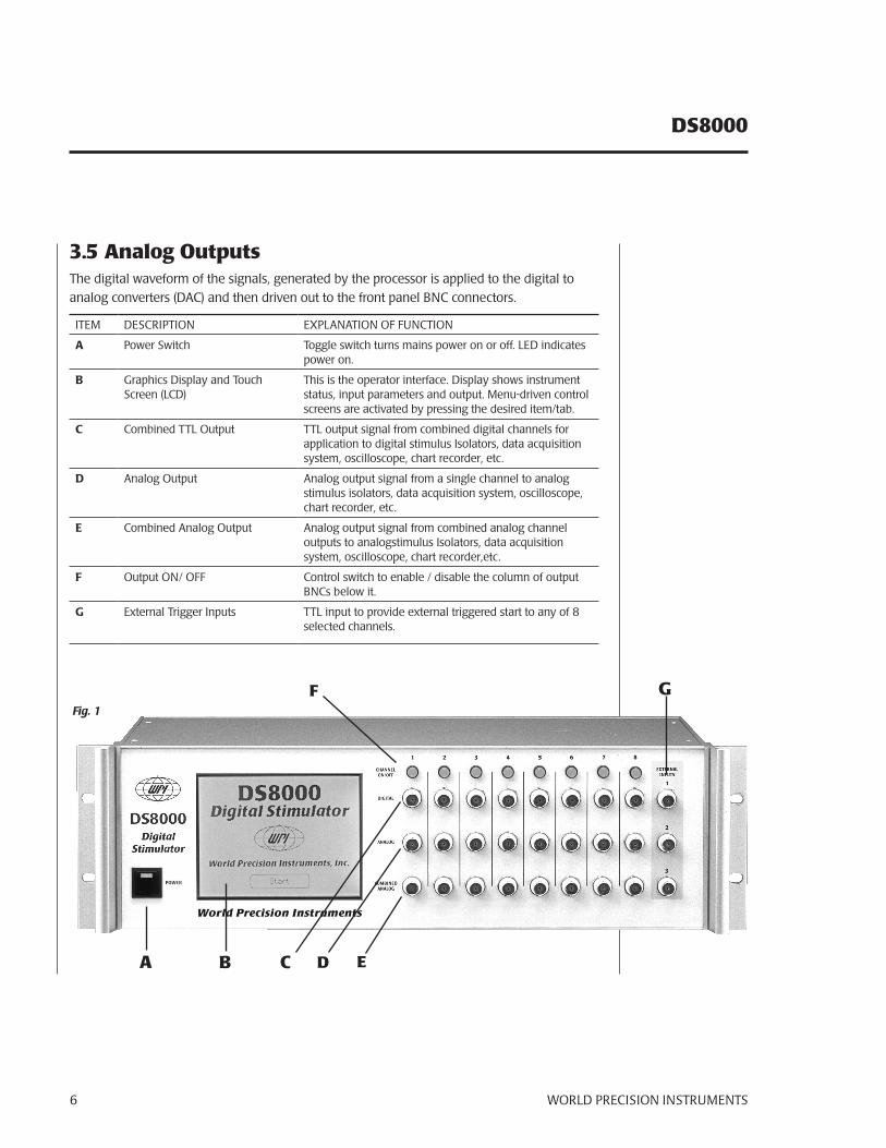
3.5 Analog OutputsThe digital waveform of the signals, generated by the processor is applied to the digital to analog converters (DAC) and then driven out to the front panel BNC connectors.
ITEM DESCRIPTION EXPLANATION OF FUNCTION
A Power Switch Toggle switch turns mains power on or off. LED indicates power on.
B Graphics Display and Touch Screen (LCD)
This is the operator interface. Display shows instrument status, input parameters and output. Menu-driven control screens are activated by pressing the desired item/tab.
C Combined TTL Output TTL output signal from combined digital channels for application to digital stimulus Isolators, data acquisition system, oscilloscope, chart recorder, etc.
D Analog Output Analog output signal from a single channel to analog stimulus isolators, data acquisition system, oscilloscope, chart recorder, etc.
E Combined Analog Output Analog output signal from combined analog channel outputs to analogstimulus Isolators, data acquisition system, oscilloscope, chart recorder,etc.
F Output ON/ OFF Control switch to enable / disable the column of output BNCs below it.
G External Trigger Inputs TTL input to provide external triggered start to any of 8 selected channels.
Fig. 1
A B C D E
F G
WORLD PRECISION INSTRUMENTS 7
DS8000
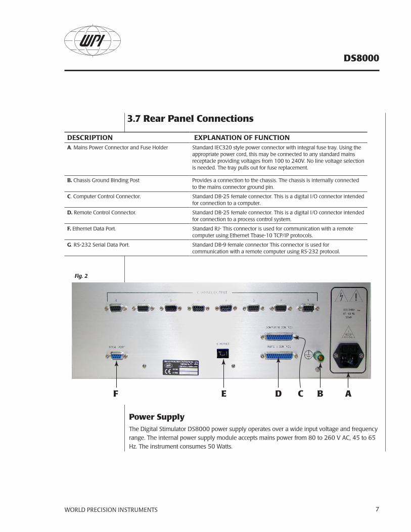
DESCRIPTION EXPLANATION OF FUNCTIONA. Mains Power Connector and Fuse Holder Standard IEC320 style power connector with integral fuse tray. Using the
appropriate power cord, this may be connected to any standard mains receptacle providing voltages from 100 to 240V. No line voltage selection is needed. The tray pulls out for fuse replacement.
B. Chassis Ground Binding Post Provides a connection to the chassis. The chassis is internally connected to the mains connector ground pin.
C. Computer Control Connector. Standard DB-25 female connector. This is a digital I/O connector intended for connection to a computer.
D. Remote Control Connector. Standard DB-25 female connector. This is a digital I/O connector intended for connection to a process control system.
F. Ethernet Data Port. Standard RJ- This connector is used for communication with a remote computer using Ethernet Tbase-10 TCP/IP protocols.
G. RS-232 Serial Data Port. Standard DB-9 female connector This connector is used for communication with a remote computer using RS-232 protocol.
ABD CEF
3.7 Rear Panel Connections
Fig. 2
Power SupplyThe Digital Stimulator DS8000 power supply operates over a wide input voltage and frequency range. The internal power supply module accepts mains power from 80 to 260 V AC, 45 to 65 Hz. The instrument consumes 50 Watts.
DS8000
WORLD PRECISION INSTRUMENTS8
Computer Control (DB25 female connector, mating connector AMP747912-2)At present, this connector is not being used.
Remote Control (DB25 female connector, mating connector AMP747912-2)This connector has 24 inputs. 16 inputs are dedicated to extra inputs, while the 8 others are inputs used by the External Trigger Inputs. All these inputs have pull up resistors and over voltage protection, grounding an input, will activate it.
Pin No. Use Pin No. Use Pin No. Use
Pin 1: Ground Pin 10: External Trigger I2 Pin 19: Channel 3 CTTL
Pin 2: Channel 2 TTL Pin 11: External Trigger I4 Pin 20: Channel 5 CTTL
Pin 3: Channel 4 TTL Pin 12: External Trigger I6 Pin 21: Channel 7 CTTL
Pin 4: Channel 6 TTL Pin 13: External Trigger I8 Pin 22: External Trigger I1
Pin 5: Channel 8 TTL Pin 14: Channel 1 TTL Pin 23: External Trigger I3
Pin 6: Channel 2 CTTL Pin 15: Channel 3 TTL Pin 24: External Trigger I5
Pin 7: Channel 4 CTTL Pin 16: Channel 5 TTL Pin 25: External Trigger I7
Pin 8: Channel 6 CTTL Pin 17: Channel 7 TTL
Pin 9: Channel 8 CTTL Pin 18: Channel 1 CTTL
Serial Interface (DB-9 female connector, mating connector AMP747904-2)Pin No. Use Pin No. Use Pin No. Use
Pin 1: DCD1 Pin 4: DTR1 Pin 7: RTS1
Pin 2: RxD1 Pin 5: GND Pin 8: CTS1
Pin 3: TxD1 Pin 6: DSR1 Pin 9: Not connected
Ethernet Connection (unshielded twisted pair [UTP] ethernet connector)Pin 1: Transmit DATA-A Pin 5: Not connected
Pin 2: Transmit DATA-B Pin 6: Receive DATA-Negative
Pin 3: Receive DATA-Positive Pin 7: Not connected
Pin 4: Not connected Pin 8: Not connected
Mains ConnectorThis is a standard IEC 3-pin power connector.
WORLD PRECISION INSTRUMENTS 9
DS8000
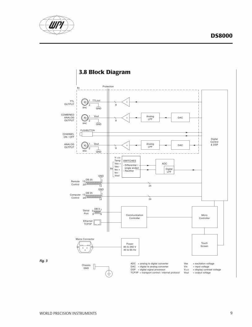
3.8 Block Diagram
Fig. 3
8x Protection
BNC
PUSHBUTTON
ANALOGOUTPUT
COMBINEDANALOGOUTPUT
TTLOUTPUT
CHANNELON / OFF
SWITCHES
- Differential / single ended- Rectifier
AnalogLPF
DAC
ADC
DigitalLPF
DigitalControl& DSP+
1
2
Vout
V LCD
TempVex +Vex -lex +lex -Vout
GND
8x
GND
DB 251325
1
14
RemoteControl 24
8
BNC
AnalogLPF
DAC+1
2
Vout
GND
8
BNC
+1
2
TTLout
GND
8
GND
DB 251325
1
14
DB 959
1
6
ComputerControl
SerialPort
EthernetTCP/IP
24
CommunicationController
MicroController
TouchScreen
Power85 to 260 V45 to 65 Hz
ADC = analog to digital converterDAC = digital to analog converterDSP = digital signal processorTCP/IP = transport control / internet protocol
Vex = excitation voltageVin = input voltageVLCD = display contrast voltageVout = output voltage
Mains Connector
ChassisGND
DS8000
WORLD PRECISION INSTRUMENTS10
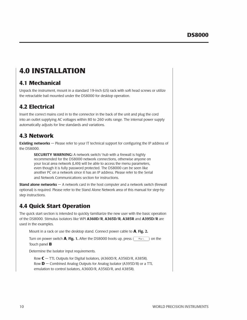
4.0 INSTALLATION
4.1 MechanicalUnpack the instrument, mount in a standard 19-inch (US) rack with soft head screws or utilize the retractable bail mounted under the DS8000 for desktop operation.
4.2 ElectricalInsert the correct mains cord in to the connector in the back of the unit and plug the cord into an outlet supplying AC voltages within 80 to 260 volts range. The internal power supply automatically adjusts for line standards and variations.
4.3 NetworkExisting networks — Please refer to your IT technical support for configuring the IP address of the DS8000.
SECURITY WARNING: A network switch/ hub with a firewall is highlyrecommended for the DS8000 network connections, otherwise anyone onyour local area network (LAN) will be able to access the menu parameters,even though it is fully password protected. The DS8000 can be seen likeanother PC on a network since it has an IP address. Please refer to the Serialand Network Communications section for instructions.
Stand alone networks — A network card in the host computer and a network switch (firewall optional) is required. Please refer to the Stand Alone Network area of this manual for step-by-step instructions.
4.4 Quick Start OperationThe quick start section is intended to quickly familiarize the new user with the basic operation of the DS8000. Stimulus isolators like WPI A360D/R, A365D/R, A385R and A395D/R are used in the examples.
Mount in a rack or use the desktop stand. Connect power cable to A, Fig. 2.
Turn on power switch A, Fig. 1. After the DS8000 boots up, press on the
Touch panel B
Determine the Isolator input requirements.
Row C — TTL Outputs for Digital Isolators, (A360D/R, A356D/R, A385R).Row D — Combined Analog Outputs for Analog Isolator (A395D/R) or a TTL emulation to control Isolators, A360D/R, A356D/R, and A385R).
WORLD PRECISION INSTRUMENTS 11
DS8000
Row E — Analog Outputs for Analog Isolator (A395D/R) or a TTL emulation to control Isolators, A360D/R, A356D/R, and A385R).
Row F — These lighted switches control the output of the selected channel on or off.
Row G — TTL inputs for external start control.
General OperationsTouch screen — A gentle touch or soft non-scratching stylus (included) is all that is required to activate a switch on the touch screen. If a touch location is not being easily activated, then move the stylus in an increasingly widening circle until it activates or use a different stylus.
CAUTION: Pushing hard on the screen does not activate a menu switch; a gentle touch works best.
Screen Navigation — The DS8000 has several menus. To page forward or move between window selections use the arrow key or tab at the top of the screen. The page forward arrow will scroll through the major sections of the DS8000, while the individual tab (at the top of each screen) will take you to that selection. The page back (located on the upper left) when shown, will back the selection completely out of an area. A window selection can be changed by touching that area, then one of the following will appear — a numeric pad, keyboard, pull-down selection or a dialog box. NOTE: Bold windows are for display only and cannot be changed. Warnings are displayed for improper entries.
Help Area — Displayed at the bottom of each screen, this area contains information about a particular option. Touch any parameter window to see the accepted values for that parameter. Page forward to the Timer Screen to see the current status of the timers. Page forward again to see the built in scope screen.
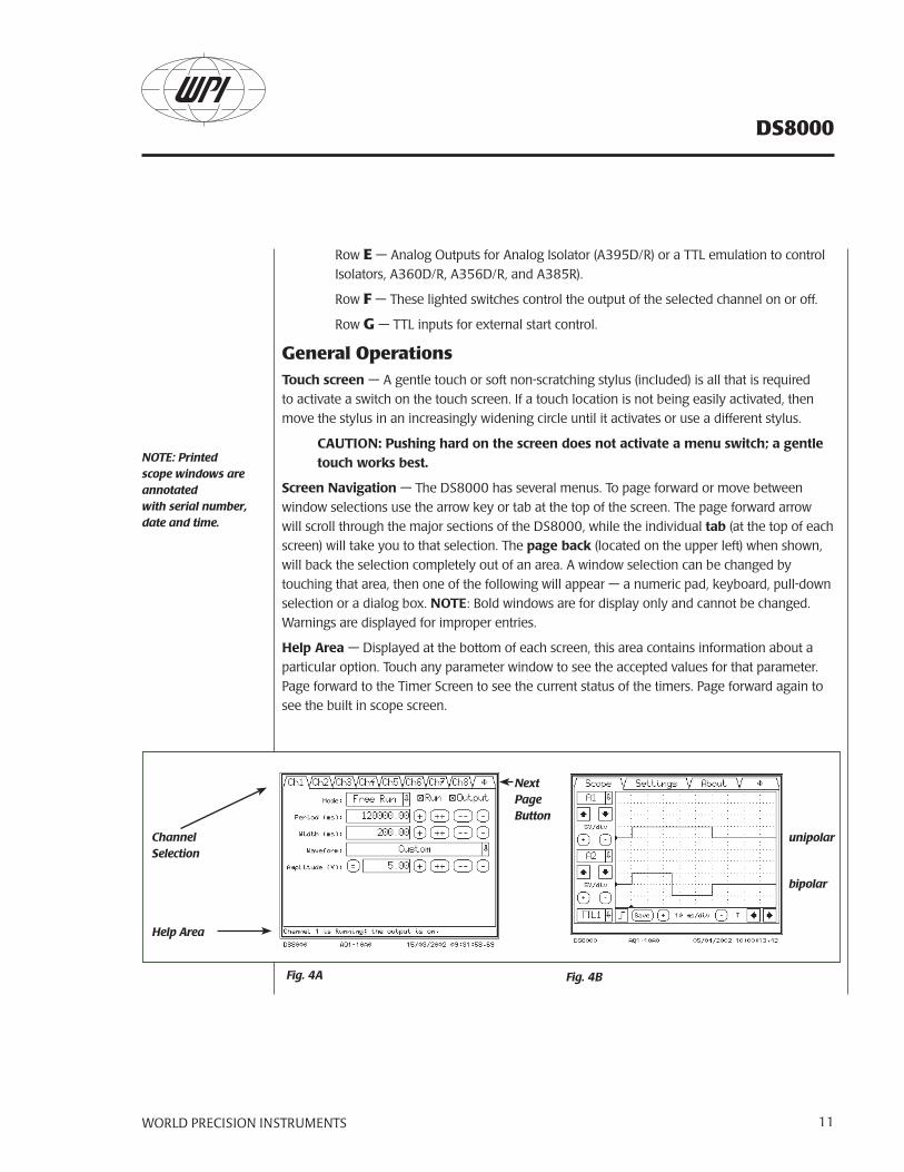
Fig. 4A Fig. 4B
Channel Selection
Help Area
NextPage Button
unipolar
bipolar
NOTE: Printedscope windows are annotatedwith serial number, date and time.
DS8000
WORLD PRECISION INSTRUMENTS12
Generation of pulse protocolsA simple unipolar (rectangular) pulse
This unipolar pulse is built of a 50 ms width of 5V amplitude within a 200 ms total period. The mode is set to free run in this example (Fig. 4A). The output viewed on the built in LCD display is shown in Fig. 4B, upper trace. The DS8000 can trigger any TTL driven device via the TTL output (Combined TTL 1) or the Analog output (Analog 1) to a Stimulus Isolation Unit (SIU).
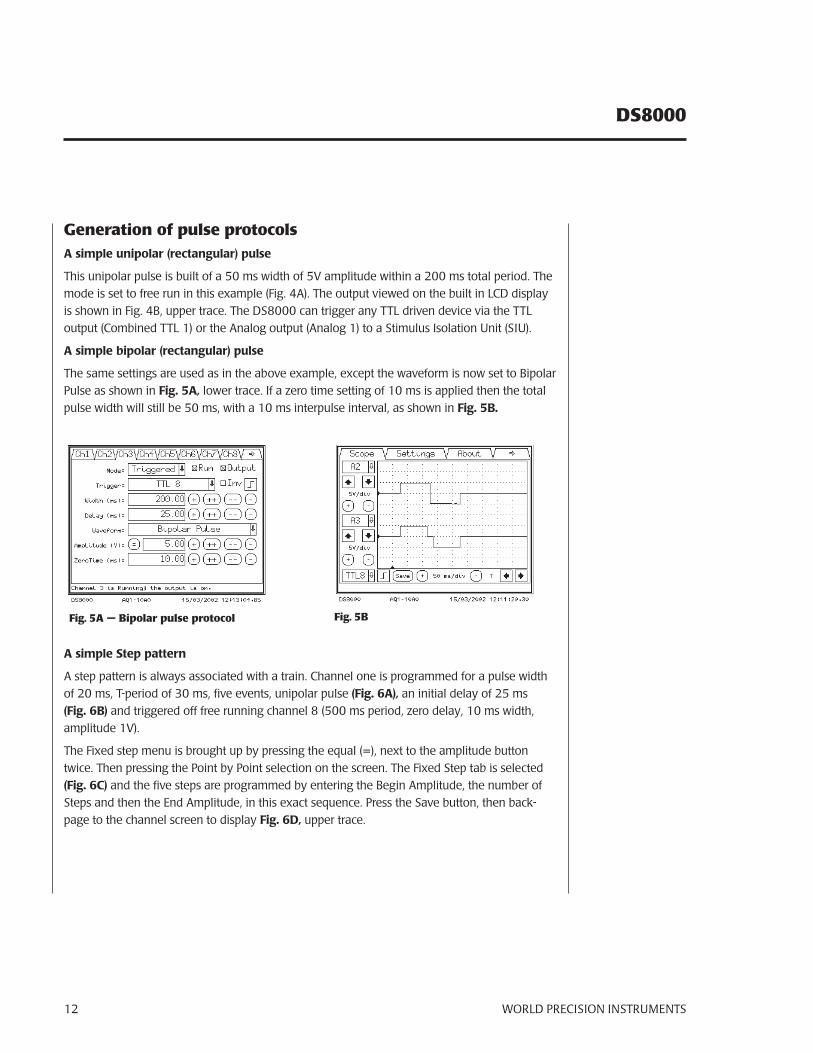
A simple bipolar (rectangular) pulse
The same settings are used as in the above example, except the waveform is now set to Bipolar Pulse as shown in Fig. 5A, lower trace. If a zero time setting of 10 ms is applied then the total pulse width will still be 50 ms, with a 10 ms interpulse interval, as shown in Fig. 5B.
Fig. 5A — Bipolar pulse protocol Fig. 5B
A simple Step pattern
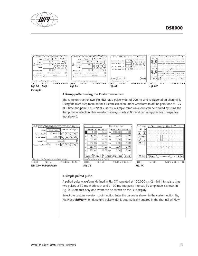
A step pattern is always associated with a train. Channel one is programmed for a pulse width of 20 ms, T-period of 30 ms, five events, unipolar pulse (Fig. 6A), an initial delay of 25 ms (Fig. 6B) and triggered off free running channel 8 (500 ms period, zero delay, 10 ms width, amplitude 1V).
The Fixed step menu is brought up by pressing the equal (=), next to the amplitude button twice. Then pressing the Point by Point selection on the screen. The Fixed Step tab is selected (Fig. 6C) and the five steps are programmed by entering the Begin Amplitude, the number of Steps and then the End Amplitude, in this exact sequence. Press the Save button, then back-page to the channel screen to display Fig. 6D, upper trace.
WORLD PRECISION INSTRUMENTS 13
DS8000
A Ramp pattern using the Custom waveform
The ramp on channel two (Fig. 6D) has a pulse width of 200 ms and is triggered off channel 8. Using the fixed step menu in the Custom selection under waveform to define point one at –2V at 0 time and point 2 at +2V at 200 ms. A simple ramp waveform can be created by using the Ramp menu selection; this waveform always starts at 0 V and can ramp positive or negative (not shown).
A simple paired pulse
A paired pulse waveform (defined in Fig. 7A) repeated at 120,000 ms (2 min.) intervals, using two pulses of 50 ms width each and a 100 ms interpulse interval, 5V amplitude is shown in Fig. 7C. Note that only one event can be shown on the LCD display.
Select the custom waveform point editor. Enter the values as shown in the custom editor, Fig. 7B. Press (SAVE) when done (the pulse width is automatically entered in the channel window.
Fig. 7B
Fig. 6A— Step
Example
Fig. 6B Fig. 6C Fig. 6D
Fig. 7A— Paired Pulse Fig. 7C
DS8000
WORLD PRECISION INSTRUMENTS14
5.0 OPERATION
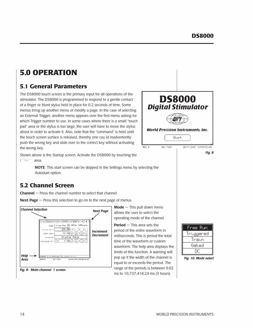
5.1 General ParametersThe DS8000 touch screen is the primary input for all operations of the stimulator. The DS8000 is programmed to respond to a gentle contact of a finger or blunt stylus held in place for 0.2 seconds of time. Some menus bring up another menu or modify a page. In the case of selecting an External Trigger, another menu appears over the first menu asking for which Trigger number to use. In some cases where there is a small “touch pad” area or the stylus is too large, the user will have to move the stylus about in order to activate it. Also, note that the “command” is held until the touch screen surface is released, thereby one cou ld inadvertently push the wrong key and slide over to the correct key without activating the wrong key.
Shown above is the Startup screen. Activate the DS8000 by touching the area.
NOTE: This start screen can be skipped in the Settings menu by selecting the Autostart option.
5.2 Channel ScreenChannel — Press the channel number to select that channel.
Next Page — Press this selection to go on to the next page of menus.
Mode — This pull down menu allows the user to select the operating mode of the channel.
Period — This area sets the period of the entire waveform in milliseconds. This is period the total time of the waveform or custom waveform. The help area displays the limits of this function. A warning will pop up if the width of the channel is equal to or exceeds the period. The range of the periods is between 0.02 ms to 10,737,418.24 ms (3 hours).
Fig. 8
Fig. 10: Mode select
Fig. 9: Main channel 1 screen
Next PageChannel Selection
Increment Decrement
Help Area
WORLD PRECISION INSTRUMENTS 15
DS8000
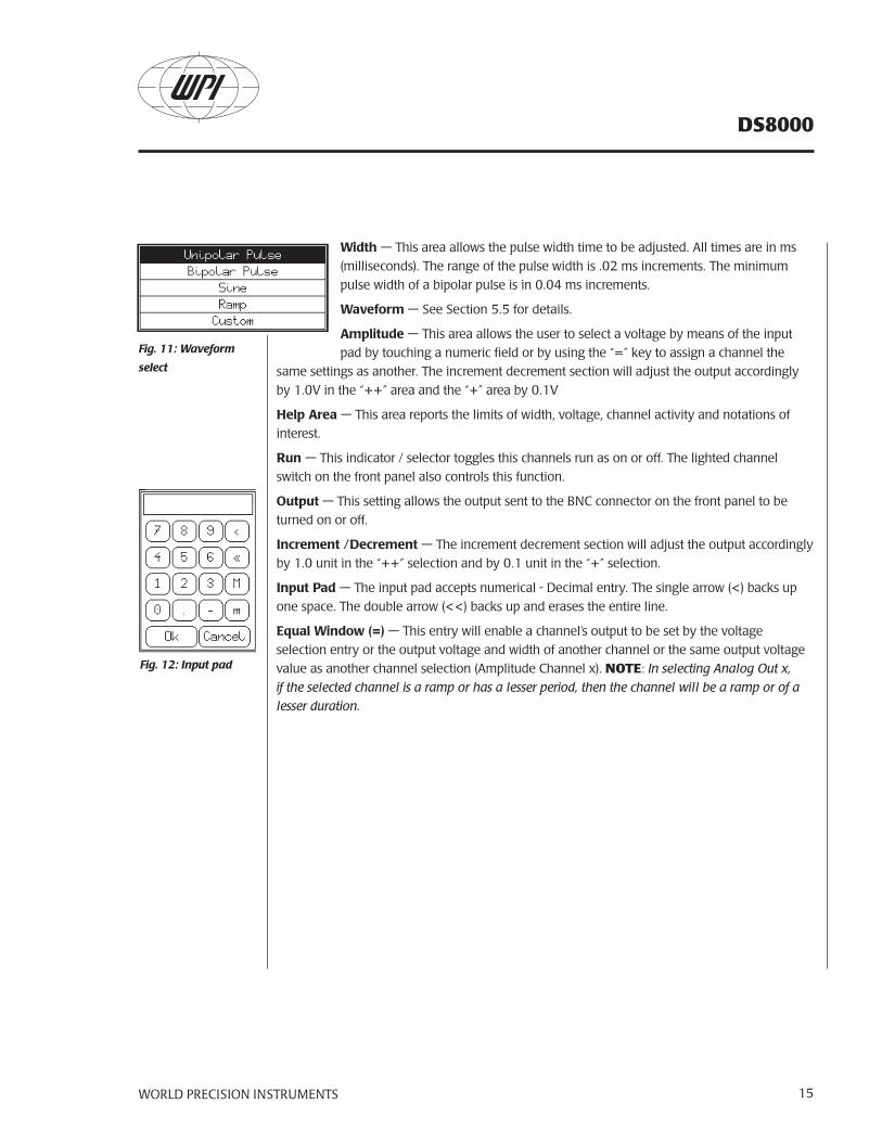
Width — This area allows the pulse width time to be adjusted. All times are in ms (milliseconds). The range of the pulse width is .02 ms increments. The minimum pulse width of a bipolar pulse is in 0.04 ms increments.
Waveform — See Section 5.5 for details.
Amplitude — This area allows the user to select a voltage by means of the input pad by touching a numeric field or by using the “=” key to assign a channel the
same settings as another. The increment decrement section will adjust the output accordingly by 1.0V in the “++” area and the “+” area by 0.1V
Help Area — This area reports the limits of width, voltage, channel activity and notations of interest.
Run — This indicator / selector toggles this channels run as on or off. The lighted channel switch on the front panel also controls this function.
Output — This setting allows the output sent to the BNC connector on the front panel to be turned on or off.
Increment /Decrement — The increment decrement section will adjust the output accordingly by 1.0 unit in the “++” selection and by 0.1 unit in the “+” selection.
Input Pad — The input pad accepts numerical - Decimal entry. The single arrow (<) backs up one space. The double arrow (<<) backs up and erases the entire line.
Equal Window (=) — This entry will enable a channel’s output to be set by the voltage selection entry or the output voltage and width of another channel or the same output voltage value as another channel selection (Amplitude Channel x). NOTE: In selecting Analog Out x, if the selected channel is a ramp or has a lesser period, then the channel will be a ramp or of a lesser duration.
Fig. 12: Input pad
Fig. 11: Waveform
select
DS8000
WORLD PRECISION INSTRUMENTS16
5.3 Trigger and Mode Screen Detail
Fig. 13: Trigger Screen
Gate Off
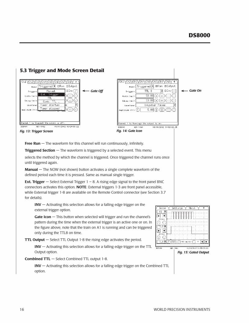
Free Run — The waveform for this channel will run continuously, infinitely.
Triggered Section — The waveform is triggered by a selected event. This menu
selects the method by which the channel is triggered. Once triggered the channel runs once until triggered again.
Manual — The NOW (not shown) button activates a single complete waveform of the defined period each time it is pressed. Same as manual single trigger.
Ext. Trigger — Select External Trigger 1 – 8. A rising edge signal to the front panel BNC connectors activates this option. NOTE: External triggers 1-3 are front panel accessible, while External trigger 1-8 are available on the Remote Control connector (see Section 3.7 for details).
INV — Activating this selection allows for a falling edge trigger on the external trigger option.
Gate Icon — This button when selected will trigger and run the channel’s pattern during the time when the external trigger is an active one or on. In the figure above, note that the train on A1 is running and can be triggered only during the TTL8 on time.
TTL Output — Select TTL Output 1-8 the rising edge activates the period.
INV — Activating this selection allows for a falling edge trigger on the TTL Output option.
Combined TTL — Select Combined TTL output 1-8.
INV — Activating this selection allows for a falling edge trigger on the Combined TTL option.
Fig. 14: Gate Icon
Gate On
Fig. 15: Gated Output
WORLD PRECISION INSTRUMENTS 17
DS8000
Timer started 1-3 — Selects one of three Internal clock timers to trigger the channel on starting (See section 5.6 for timer setup).
Timer stopped 1-3 — Select one of three Internal clock timers to trigger the channel on stopping (See section 5.6 for timer setup).
Train — This selection brings up a new screen (Defined in Train Section)
Gated — In this mode the stimulators pattern runs while the gated input is active (high).
DC — This selection puts out a continuous voltage set by the voltage parameter
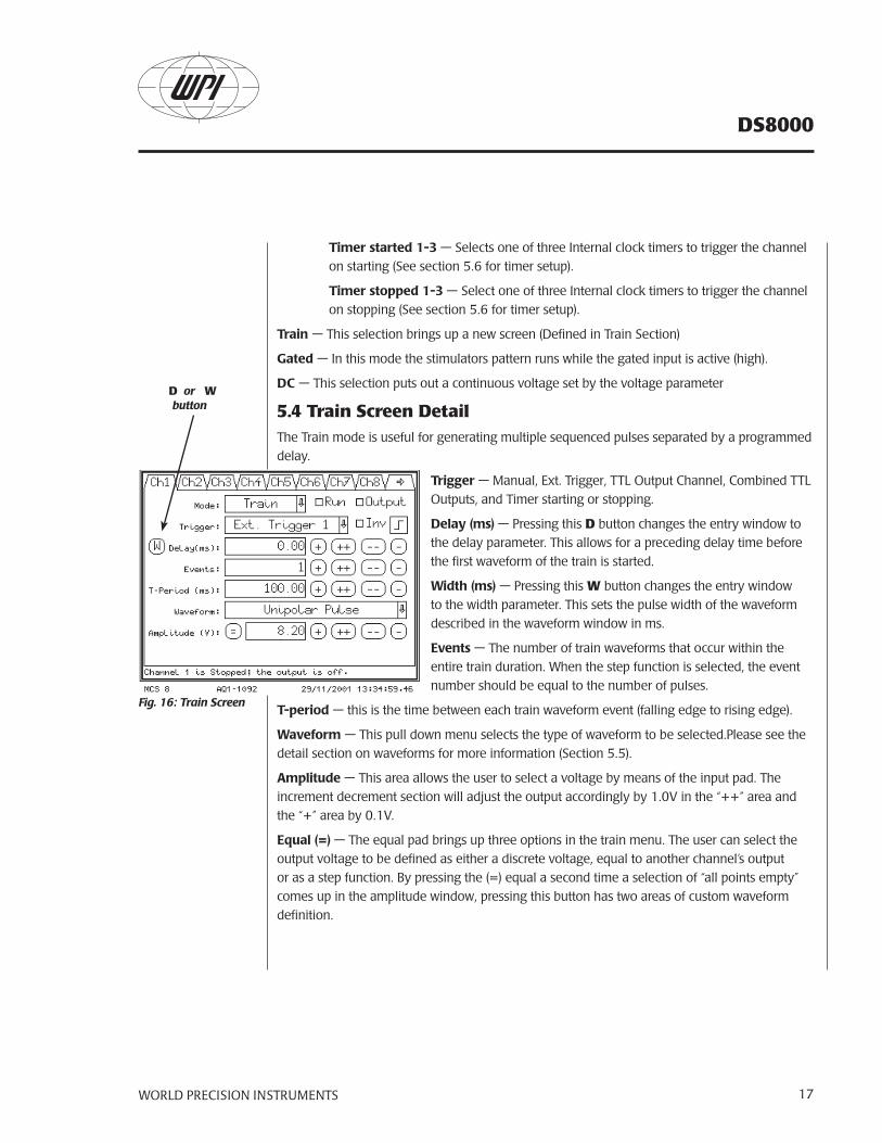
5.4 Train Screen DetailThe Train mode is useful for generating multiple sequenced pulses separated by a programmed delay.
Trigger — Manual, Ext. Trigger, TTL Output Channel, Combined TTL Outputs, and Timer starting or stopping.
Delay (ms) — Pressing this D button changes the entry window to the delay parameter. This allows for a preceding delay time before the first waveform of the train is started.
Width (ms) — Pressing this W button changes the entry window to the width parameter. This sets the pulse width of the waveform described in the waveform window in ms.
Events — The number of train waveforms that occur within the entire train duration. When the step function is selected, the event number should be equal to the number of pulses.
T-period — this is the time between each train waveform event (falling edge to rising edge).
Waveform — This pull down menu selects the type of waveform to be selected.Please see the detail section on waveforms for more information (Section 5.5).
Amplitude — This area allows the user to select a voltage by means of the input pad. The increment decrement section will adjust the output accordingly by 1.0V in the “++” area and the “+” area by 0.1V.
Equal (=) — The equal pad brings up three options in the train menu. The user can select the output voltage to be defined as either a discrete voltage, equal to another channel’s output or as a step function. By pressing the (=) equal a second time a selection of “all points empty” comes up in the amplitude window, pressing this button has two areas of custom waveform definition.
D or W button
Fig. 16: Train Screen
DS8000
WORLD PRECISION INSTRUMENTS18
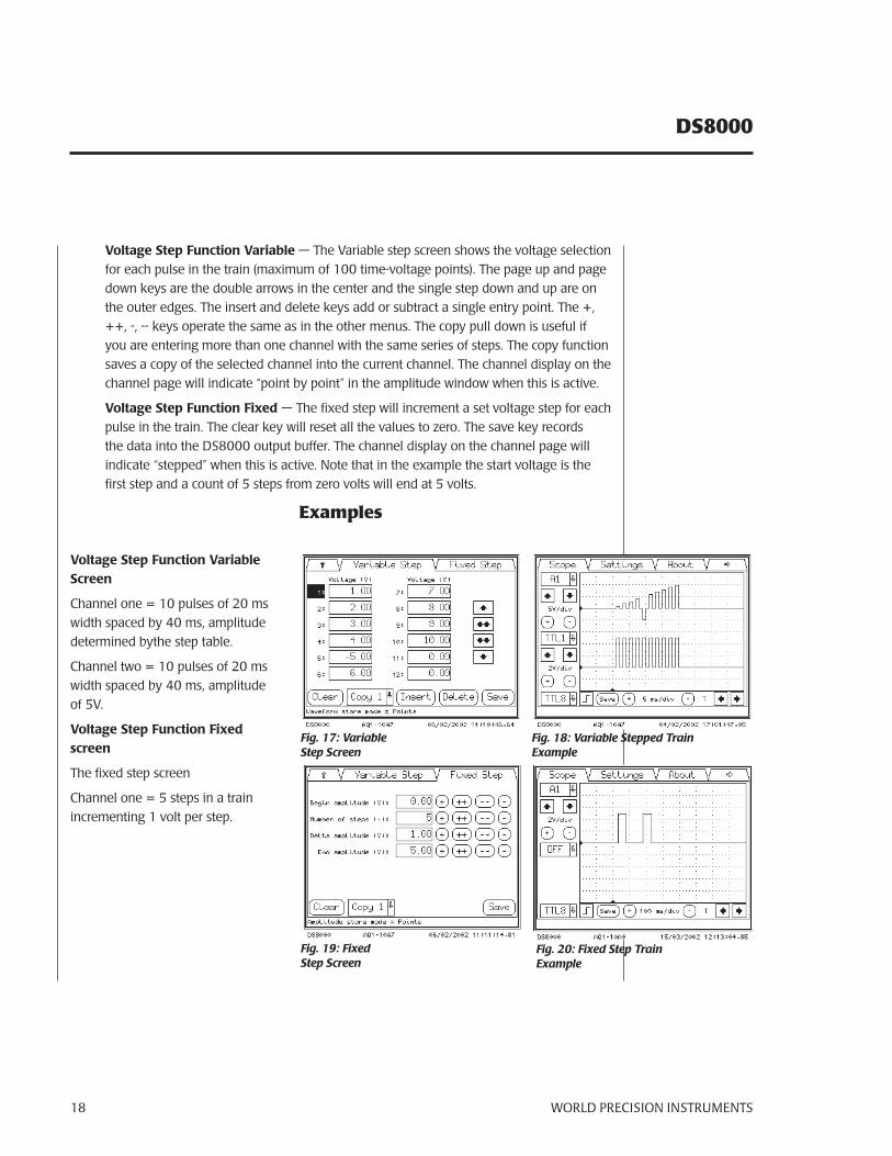
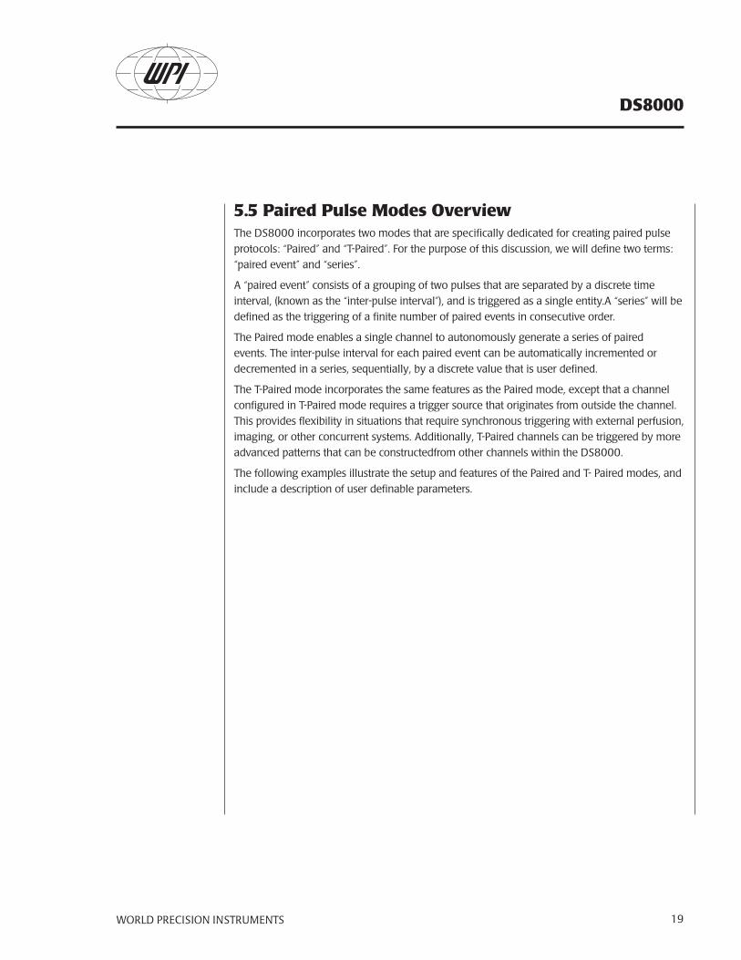
Voltage Step Function Variable — The Variable step screen shows the voltage selection for each pulse in the train (maximum of 100 time-voltage points). The page up and page down keys are the double arrows in the center and the single step down and up are on the outer edges. The insert and delete keys add or subtract a single entry point. The +, ++, -, -- keys operate the same as in the other menus. The copy pull down is useful if you are entering more than one channel with the same series of steps. The copy function saves a copy of the selected channel into the current channel. The channel display on the channel page will indicate “point by point” in the amplitude window when this is active.
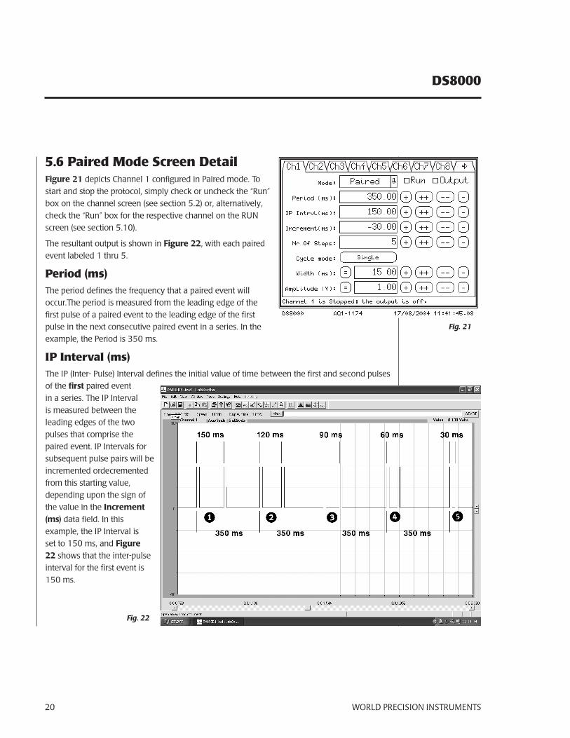
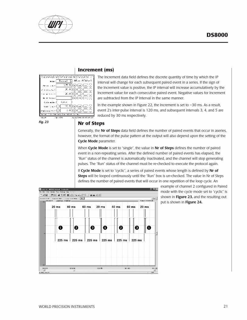
Voltage Step Function Fixed — The fixed step will increment a set voltage step for each pulse in the train. The clear key will reset all the values to zero. The save key records the data into the DS8000 output buffer. The channel display on the channel page will indicate “stepped” when this is active. Note that in the example the start voltage is the first step and a count of 5 steps from zero volts will end at 5 volts.
Examples
Voltage Step Function Variable Screen
Channel one = 10 pulses of 20 ms width spaced by 40 ms, amplitude determined bythe step table.
Channel two = 10 pulses of 20 ms width spaced by 40 ms, amplitude of 5V.
Voltage Step Function Fixed screen
The fixed step screen
Channel one = 5 steps in a train incrementing 1 volt per step.
Fig. 17: Variable Step Screen
Fig. 19: Fixed Step Screen
Fig. 18: Variable Stepped Train Example
Fig. 20: Fixed Step Train Example
WORLD PRECISION INSTRUMENTS 19
DS8000
5.5 Paired Pulse Modes OverviewThe DS8000 incorporates two modes that are specifically dedicated for creating paired pulse protocols: “Paired” and “T-Paired”. For the purpose of this discussion, we will define two terms: “paired event” and “series”.
A “paired event” consists of a grouping of two pulses that are separated by a discrete time interval, (known as the “inter-pulse interval”), and is triggered as a single entity.A “series” will be defined as the triggering of a finite number of paired events in consecutive order.
The Paired mode enables a single channel to autonomously generate a series of paired events. The inter-pulse interval for each paired event can be automatically incremented or decremented in a series, sequentially, by a discrete value that is user defined.
The T-Paired mode incorporates the same features as the Paired mode, except that a channel configured in T-Paired mode requires a trigger source that originates from outside the channel. This provides flexibility in situations that require synchronous triggering with external perfusion, imaging, or other concurrent systems. Additionally, T-Paired channels can be triggered by more advanced patterns that can be constructedfrom other channels within the DS8000.
The following examples illustrate the setup and features of the Paired and T- Paired modes, and include a description of user definable parameters.
DS8000
WORLD PRECISION INSTRUMENTS20
5.6 Paired Mode Screen DetailFigure 21 depicts Channel 1 configured in Paired mode. To start and stop the protocol, simply check or uncheck the “Run” box on the channel screen (see section 5.2) or, alternatively, check the “Run” box for the respective channel on the RUN screen (see section 5.10).
The resultant output is shown in Figure 22, with each paired event labeled 1 thru 5.
Period (ms)The period defines the frequency that a paired event will occur.The period is measured from the leading edge of the first pulse of a paired event to the leading edge of the first pulse in the next consecutive paired event in a series. In the example, the Period is 350 ms.
IP Interval (ms)The IP (Inter- Pulse) Interval defines the initial value of time between the first and second pulses of the first paired event in a series. The IP Interval is measured between the leading edges of the two pulses that comprise the paired event. IP Intervals for subsequent pulse pairs will be incremented ordecremented from this starting value, depending upon the sign of the value in the Increment (ms) data field. In this example, the IP Interval is set to 150 ms, and Figure 22 shows that the inter-pulse interval for the first event is 150 ms.
Fig. 21
Fig. 22
WORLD PRECISION INSTRUMENTS 21
DS8000
Increment (ms)The Increment data field defines the discrete quantity of time by which the IP interval will change for each subsequent paired event in a series. If the sign of the Increment value is positive, the IP interval will increase accumulatively by the Increment value for each consecutive paired event. Negative values for Increment are subtracted from the IP Interval in the same manner.
In the example shown in Figure 22, the Increment is set to –30 ms. As a result, event 2’s inter-pulse interval is 120 ms, and subsequent intervals 3, 4, and 5 are reduced by 30 ms respectively.
Nr of StepsGenerally, the Nr of Steps data field defines the number of paired events that occur in aseries, however, the format of the pulse pattern at the output will also depend upon the setting of the Cycle Mode parameter.
When Cycle Mode is set to “single”, the value in Nr of Steps defines the number of paired event in a non-repeating series. After the defined number of paired events has elapsed, the “Run” status of the channel is automatically inactivated, and the channel will stop generating pulses. The “Run” status of the channel must be re-checked to execute the protocol again.
If Cycle Mode is set to “cyclic”, a series of paired events whose length is defined by Nr of Steps will be looped continuously until the “Run” box is un-checked. The value in Nr of Steps defines the number of paired events that will occur in one repetition of the loop cycle. An
example of channel 2 configured in Paired mode with the cycle mode set to “cyclic” is shown in Figure 23, and the resulting out put is shown in Figure 24.
Fig. 23
DS8000
WORLD PRECISION INSTRUMENTS22
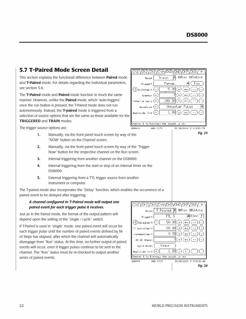
5.7 T-Paired Mode Screen DetailThis section explains the functional difference between Paired mode and T-Paired mode. For details regarding the individual parameters, see section 5.6.
The T-Paired mode and Paired mode function in much the same manner. However, unlike the Paired mode, which “auto-triggers” once the run button is pressed, the T-Paired mode does not run autonomously. Instead, the T-paired mode is triggered from a selection of source options that are the same as those available for the TRIGGERED and TRAIN modes.
The trigger source options are:
1. Manually, via the front panel touch screen by way of the “NOW” button on the Channel screen.
2. Manually, via the front panel touch screen by way of the “Trigger Now” button for the respective channel on the Run screen.
3. Internal triggering from another channel on the DS8000.
4. Internal triggering from the start or stop of an internal timer on the DS8000.
5. External triggering from a TTL trigger source from another instrument or computer.
The T-paired mode also incorporates the “Delay” function, which enables the occurrence of a paired event to be delayed after triggering.
A channel configured in T-Paired mode will output one paired event for each trigger pulse it receives.
Just as in the Paired mode, the format of the output pattern will depend upon the setting of the “single / cyclic” switch.
If T-Paired is used in “single” mode, one paired event will occur for each trigger pulse until the number of paired events defined by Nr of Steps has elapsed, after which the channel will automatically disengage from “Run” status. At this time, no further output of paired events will occur, even if trigger pulses continue to be sent to the channel. The “Run” status must be re-checked to output another series of paired events.
Fig. 25
Fig. 26
WORLD PRECISION INSTRUMENTS 23
DS8000
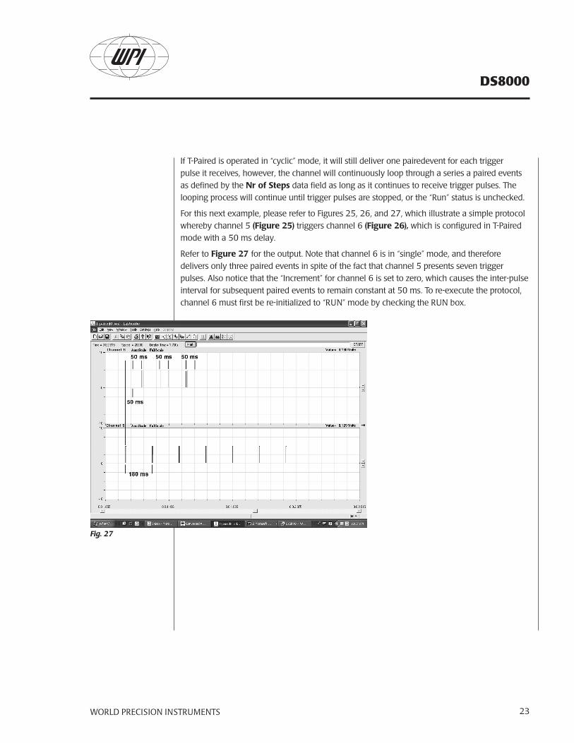
If T-Paired is operated in “cyclic” mode, it will still deliver one pairedevent for each trigger pulse it receives, however, the channel will continuously loop through a series a paired events as defined by the Nr of Steps data field as long as it continues to receive trigger pulses. The looping process will continue until trigger pulses are stopped, or the “Run” status is unchecked.
For this next example, please refer to Figures 25, 26, and 27, which illustrate a simple protocol whereby channel 5 (Figure 25) triggers channel 6 (Figure 26), which is configured in T-Paired mode with a 50 ms delay.
Refer to Figure 27 for the output. Note that channel 6 is in “single” mode, and therefore delivers only three paired events in spite of the fact that channel 5 presents seven trigger pulses. Also notice that the “Increment” for channel 6 is set to zero, which causes the inter-pulse interval for subsequent paired events to remain constant at 50 ms. To re-execute the protocol, channel 6 must first be re-initialized to “RUN” mode by checking the RUN box.
Fig. 27
DS8000
WORLD PRECISION INSTRUMENTS24
Fig. 32 Ramp
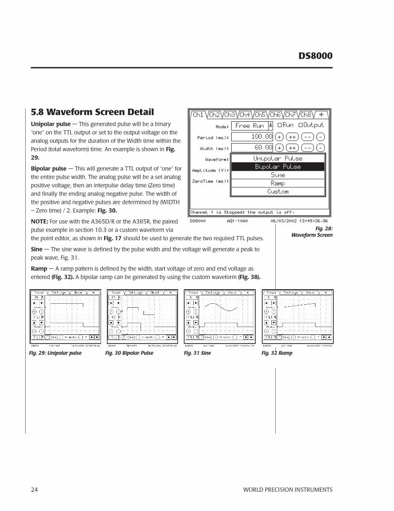
5.8 Waveform Screen DetailUnipolar pulse — This generated pulse will be a binary “one” on the TTL output or set to the output voltage on the analog outputs for the duration of the Width time within the Period (total waveform) time. An example is shown in Fig. 29.
Bipolar pulse — This will generate a TTL output of “one” for the entire pulse width. The analog pulse will be a set analog positive voltage, then an interpulse delay time (Zero time) and finally the ending analog negative pulse. The width of the positive and negative pulses are determined by (WIDTH – Zero time) / 2. Example: Fig. 30.
NOTE: For use with the A365D/R or the A385R, the paired pulse example in section 10.3 or a custom waveform via the point editor, as shown in Fig. 17 should be used to generate the two required TTL pulses.
Sine — The sine wave is defined by the pulse width and the voltage will generate a peak to peak wave, Fig. 31.
Ramp — A ramp pattern is defined by the width, start voltage of zero and end voltage as entered (Fig. 32). A bipolar ramp can be generated by using the custom waveform (Fig. 38).
Fig. 28: Waveform Screen
Fig. 29: Unipolar pulse Fig. 30 Bipolar Pulse Fig. 31 Sine
WORLD PRECISION INSTRUMENTS 25
DS8000
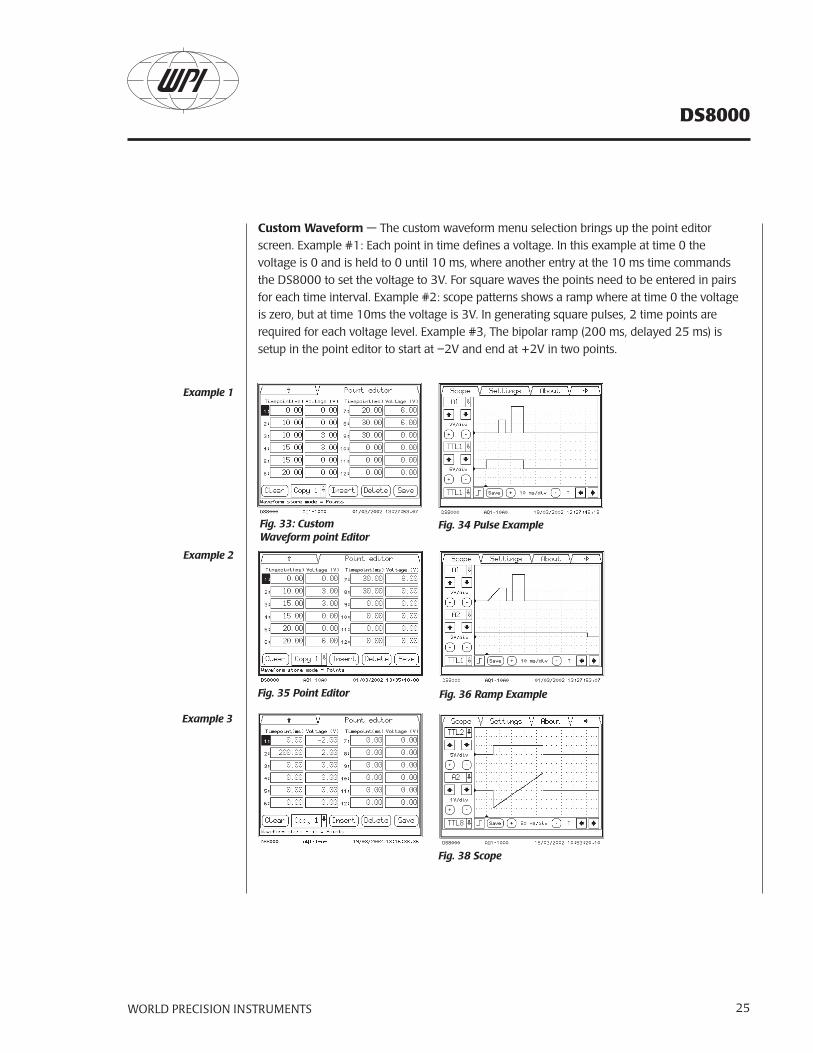
Custom Waveform — The custom waveform menu selection brings up the point editor screen. Example #1: Each point in time defines a voltage. In this example at time 0 the voltage is 0 and is held to 0 until 10 ms, where another entry at the 10 ms time commands the DS8000 to set the voltage to 3V. For square waves the points need to be entered in pairs for each time interval. Example #2: scope patterns shows a ramp where at time 0 the voltage is zero, but at time 10ms the voltage is 3V. In generating square pulses, 2 time points are required for each voltage level. Example #3, The bipolar ramp (200 ms, delayed 25 ms) is setup in the point editor to start at –2V and end at +2V in two points.
Fig. 33: Custom Waveform point Editor
Fig. 34 Pulse Example
Fig. 35 Point Editor Fig. 36 Ramp Example
Fig. 38 Scope
Example 1
Example 2
Example 3
DS8000
WORLD PRECISION INSTRUMENTS26
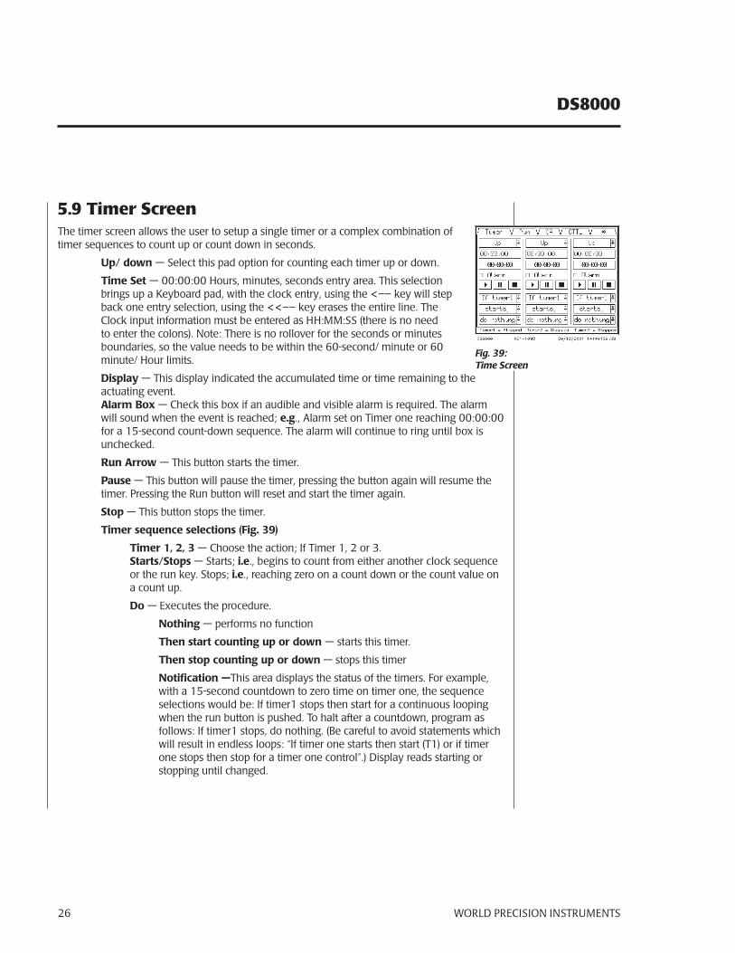
5.9 Timer ScreenThe timer screen allows the user to setup a single timer or a complex combination of timer sequences to count up or count down in seconds.
Up/ down — Select this pad option for counting each timer up or down.
Time Set — 00:00:00 Hours, minutes, seconds entry area. This selection brings up a Keyboard pad, with the clock entry, using the <–– key will step back one entry selection, using the <<–– key erases the entire line. The Clock input information must be entered as HH:MM:SS (there is no need to enter the colons). Note: There is no rollover for the seconds or minutes boundaries, so the value needs to be within the 60-second/ minute or 60 minute/ Hour limits.
Display — This display indicated the accumulated time or time remaining to the actuating event.Alarm Box — Check this box if an audible and visible alarm is required. The alarm will sound when the event is reached; e.g., Alarm set on Timer one reaching 00:00:00 for a 15-second count-down sequence. The alarm will continue to ring until box is unchecked.
Run Arrow — This button starts the timer.
Pause — This button will pause the timer, pressing the button again will resume the timer. Pressing the Run button will reset and start the timer again.
Stop — This button stops the timer.
Timer sequence selections (Fig. 39)
Timer 1, 2, 3 — Choose the action; If Timer 1, 2 or 3.Starts/Stops — Starts; i.e., begins to count from either another clock sequence or the run key. Stops; i.e., reaching zero on a count down or the count value on a count up.
Do — Executes the procedure.
Nothing — performs no function
Then start counting up or down — starts this timer.
Then stop counting up or down — stops this timer
Notification —This area displays the status of the timers. For example, with a 15-second countdown to zero time on timer one, the sequence selections would be: If timer1 stops then start for a continuous looping when the run button is pushed. To halt after a countdown, program as follows: If timer1 stops, do nothing. (Be careful to avoid statements which will result in endless loops: “If timer one starts then start (T1) or if timer one stops then stop for a timer one control”.) Display reads starting or stopping until changed.
Fig. 39: Time Screen
WORLD PRECISION INSTRUMENTS 27
DS8000
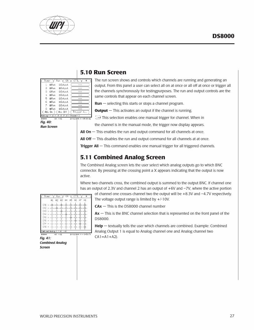
5.10 Run ScreenThe run screen shows and controls which channels are running and generating an output. From this panel a user can select all on at once or all off at once or trigger all the channels synchronously for testingpurposes. The run and output controls are the same controls that appear on each channel screen.
Run — selecting this starts or stops a channel program.
Output — This activates an output if the channel is running.
— This selection enables one manual trigger for channel. When in
the channel is in the manual mode, the trigger now display appears.
All On — This enables the run and output command for all channels at once.
All Off — This disables the run and output command for all channels at at once.
Trigger All — This command enables one manual trigger for all triggered channels.
5.11 Combined Analog ScreenThe Combined Analog screen lets the user select which analog outputs go to which BNC connector. By pressing at the crossing point a X appears indicating that the output is now active.
Where two channels cross, the combined output is summed to the output BNC. If channel one has an output of 2.3V and channel 2 has an output of +6V and –7V, where the active portion
of channel one crosses channel two the output will be +8.3V and –4.7V respectively. The voltage output range is limited by +/-10V.
CAx — This is the DS8000 channel number
Ax — This is the BNC channel selection that is represented on the front panel of the DS8000.
Help — textually tells the user which channels are combined. Example: Combined Analog Output 1 is equal to Analog channel one and Analog channel two CA1=A1+A2).
Fig. 40: Run Screen
Fig. 41:Combined Analog Screen
DS8000
WORLD PRECISION INSTRUMENTS28
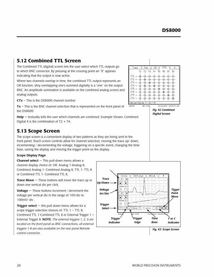
5.12 Combined TTL ScreenThe Combined TTL (digital) screen lets the user select which TTL outputs go to which BNC connector. By pressing at the crossing point an “X” appears indicating that the output is now active.
Where two channels overlap in time, the combined TTL output represents an OR function. (Any overlapping one’s summed digitally is a “one” on the output BNC. An amplitude summation is available on the combined analog screen and analog outputs.
CTx – This is the DS8000 channel number
Tx – This is the BNC channel selection that is represented on the front panel of the DS8000
Help — textually tells the user which channels are combined. Example Shown: Combined Digital 4 is the combination of T2 + T4.
5.13 Scope ScreenThe scope screen is a convenient display of two patterns as they are being sent to the front panel. Touch screen controls allow for channel selection, moving the trace up/ down, incrementing / decrementing the voltage, triggering on a specific event, changing the time base, saving the display and moving the trigger point on the display.
Scope Display Page
Channel select — This pull-down menu allows a channel display choice of: Off, Analog 1-Analog 8, Combined Analog 1- Combined Analog 8, TTL 1- TTL 8 or Combined TTL 1- Combined TTL 8.
Trace Move — These buttons will move the trace up or down one vertical div per click.
Voltage — These buttons increment / decrement the voltage per vertical div in the range of 10V/div to 100mV/ div .
Trigger select — this pull down menu allows for a scope trigger selection choices of: TTL 1 – TTL 8, Combined TTL 1-Combined TTL 8 or External Trigger 1 – External Trigger 8. NOTE: The external triggers 1, 2, 3 are located on the front panel as BNC connections, all external triggers 1-8 are also available on the rear panel Remote control connector.
Fig. 43: Scope Screen
Fig. 42 Combined Digital Screen
Trace Up/Down
VoltageInc/Dec
TriggerSelect
TriggerIndicator
TriggerEdge
TimeBase
T or CIndicator
TiggerPoint Move
WORLD PRECISION INSTRUMENTS 29
DS8000
Trigger edge — This button allows for a leading or falling edge trigger.
Trigger indicator – This point is the indicator of the triggered point in time (Indicated by a small arrow pointing up).
Trigger point move — These increment decrement buttons control the horizontal placement of the trigger point.
Save — Pressing this key will save this screen to your root_ftp directory. NOTE: The FTP server emulator must be active, the network or serial program does not need to be. The file name will be stored as: Scope_03_12_2001_11_32_44.bmp. Is in the format: Scope_DD_MM_YYYY_HH_MM_SS.bmp
Time base — These increment decrement buttons control the time per horizontal division on the scope in the limits of 500 μs/div to 10 sec/div.
T or C indicator — Continuous or triggered sweep, this indicator shows whether a trace is triggered (T) if the time base is equal to or under 100 ms/div or continuous (C) if equal to or over 500 ms/div).
NOTE: The screen will display the last trace when the channel is stopped, unless the time scale is changed; then the screen is refreshed.
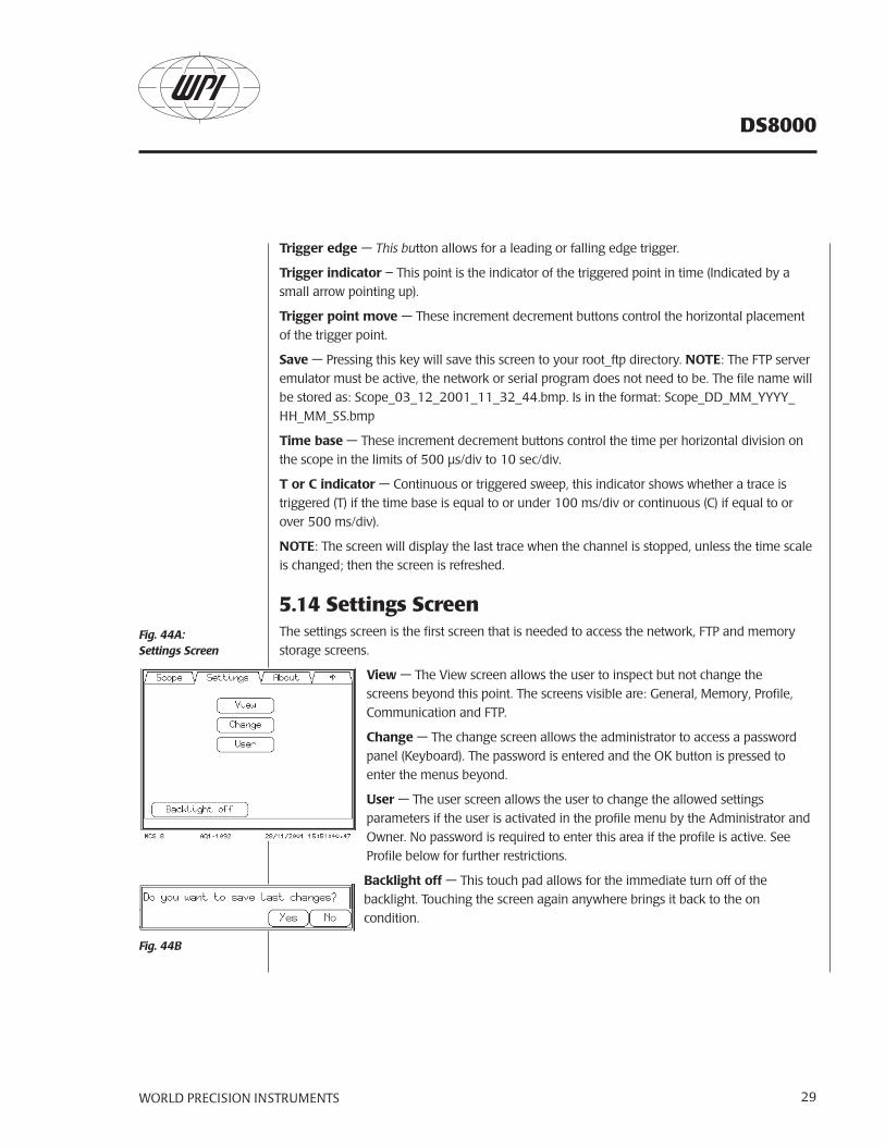
5.14 Settings ScreenThe settings screen is the first screen that is needed to access the network, FTP and memory storage screens.
View — The View screen allows the user to inspect but not change the screens beyond this point. The screens visible are: General, Memory, Profile, Communication and FTP.
Change — The change screen allows the administrator to access a password panel (Keyboard). The password is entered and the OK button is pressed to enter the menus beyond.
User — The user screen allows the user to change the allowed settings parameters if the user is activated in the profile menu by the Administrator and Owner. No password is required to enter this area if the profile is active. See Profile below for further restrictions.
Backlight off — This touch pad allows for the immediate turn off of the backlight. Touching the screen again anywhere brings it back to the on condition.
Fig. 44A:Settings Screen
Fig. 44B
DS8000
WORLD PRECISION INSTRUMENTS30
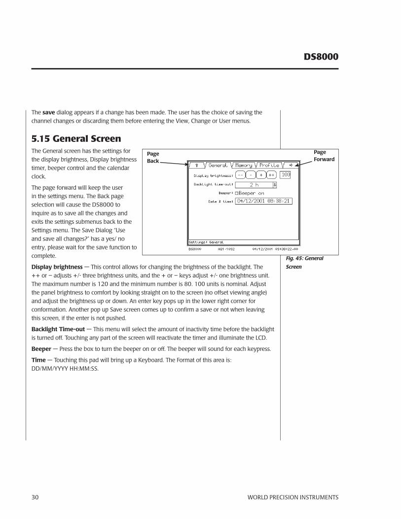
The save dialog appears if a change has been made. The user has the choice of saving the channel changes or discarding them before entering the View, Change or User menus.
5.15 General ScreenThe General screen has the settings for the display brightness, Display brightness timer, beeper control and the calendar clock.
The page forward will keep the user in the settings menu. The Back page selection will cause the DS8000 to inquire as to save all the changes and exits the settings submenus back to the Settings menu. The Save Dialog “Use and save all changes?” has a yes/ no entry, please wait for the save function to complete.
Display brightness — This control allows for changing the brightness of the backlight. The ++ or – adjusts +/- three brightness units, and the + or – keys adjust +/- one brightness unit. The maximum number is 120 and the minimum number is 80. 100 units is nominal. Adjust the panel brightness to comfort by looking straight on to the screen (no offset viewing angle) and adjust the brightness up or down. An enter key pops up in the lower right corner for conformation. Another pop up Save screen comes up to confirm a save or not when leaving this screen, if the enter is not pushed.
Backlight Time-out — This menu will select the amount of inactivity time before the backlight is turned off. Touching any part of the screen will reactivate the timer and illuminate the LCD.
Beeper — Press the box to turn the beeper on or off. The beeper will sound for each keypress.
Time — Touching this pad will bring up a Keyboard. The Format of this area is: DD/MM/YYYY HH:MM:SS.
Fig. 45: General
Screen
PageBack
PageForward
WORLD PRECISION INSTRUMENTS 31
DS8000
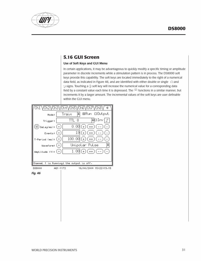
5.16 GUI ScreenUse of Soft Keys and GUI Menu
In certain applications, it may be advantageous to quickly modify a specific timing or amplitude parameter in discrete increments while a stimulation pattern is in process. The DS8000 soft keys provide this capability. The soft keys are located immediately to the right of a numerical data field, as indicated in Figure 46, and are identified with either double or single and
signs. Touching a soft key will increase the numerical value for a corresponding data field by a constant value each time it is depressed. The functions in a similar manner, but increments it by a larger amount. The incremental values of the soft keys are user definable within the GUI menu.
Fig. 46
DS8000
WORLD PRECISION INSTRUMENTS32
Changing the Values of the Soft Keys
To change the values of the soft keys, first navigate to the GUI screen. The GUI screen is located in the administrative settings menu. Navigation to the administrative settings menu from the start prompt is as follows:
Upon powering up the DS8000,
Press “start”.
Touch the upper right-hand arrow (3) times to navigate to the SCOPE screen.
Touch the “settings” tab.
Touch “change”.
Enter the administrator password (the factory default is “admin”).
Touch the “GUI” tab.
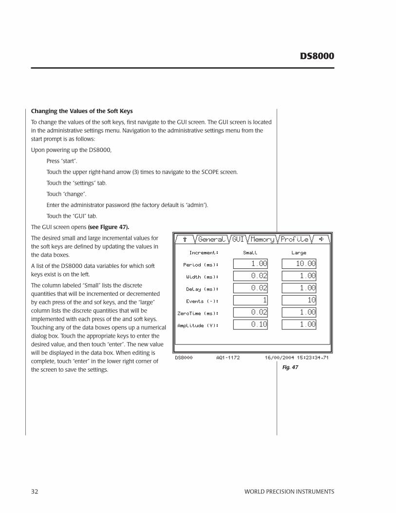
The GUI screen opens (see Figure 47).
The desired small and large incremental values for the soft keys are defined by updating the values in the data boxes.
A list of the DS8000 data variables for which soft keys exist is on the left.
The column labeled “Small” lists the discrete quantities that will be incremented or decremented by each press of the and sof keys, and the “large” column lists the discrete quantities that will be implemented with each press of the and soft keys. Touching any of the data boxes opens up a numerical dialog box. Touch the appropriate keys to enter the desired value, and then touch “enter”. The new value will be displayed in the data box. When editing is complete, touch “enter” in the lower right corner of the screen to save the settings. Fig. 47
WORLD PRECISION INSTRUMENTS 33
DS8000
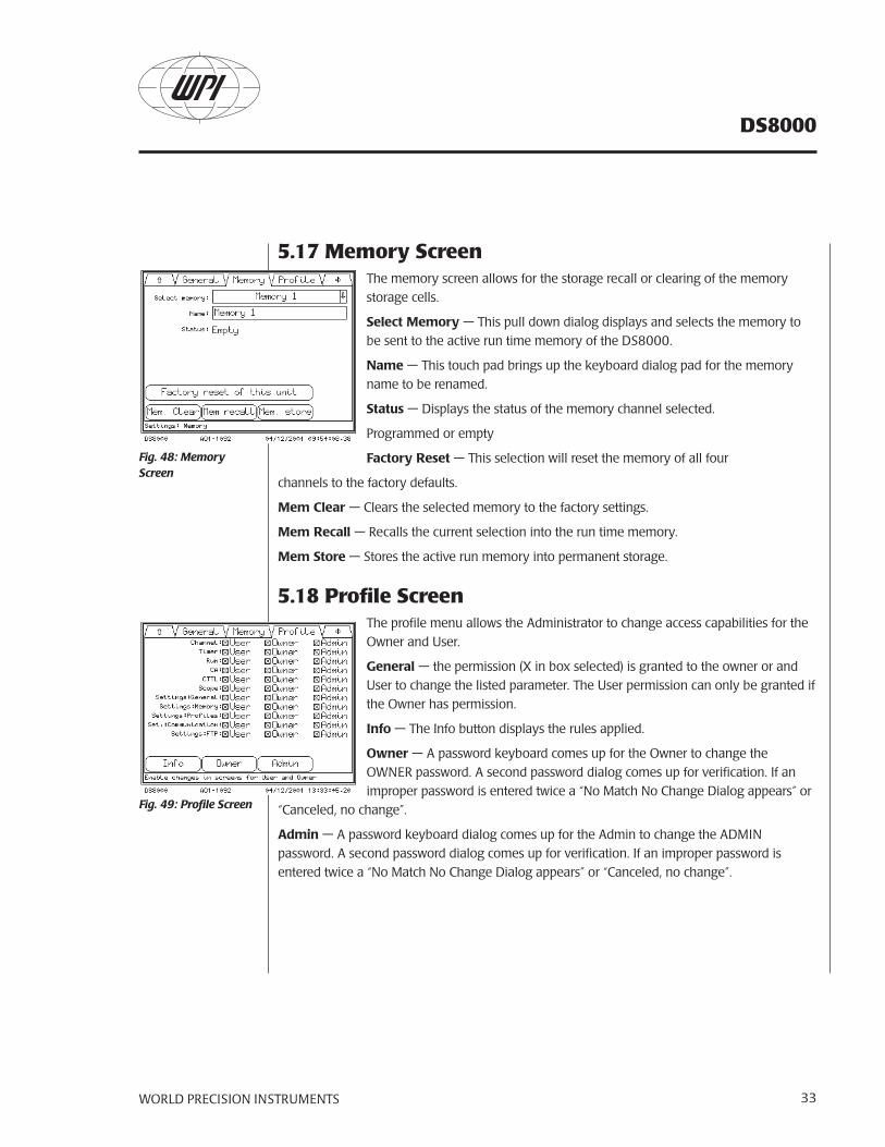
5.17 Memory ScreenThe memory screen allows for the storage recall or clearing of the memory storage cells.
Select Memory — This pull down dialog displays and selects the memory to be sent to the active run time memory of the DS8000.
Name — This touch pad brings up the keyboard dialog pad for the memory name to be renamed.
Status — Displays the status of the memory channel selected.
Programmed or empty
Factory Reset — This selection will reset the memory of all four
channels to the factory defaults.
Mem Clear — Clears the selected memory to the factory settings.
Mem Recall — Recalls the current selection into the run time memory.
Mem Store — Stores the active run memory into permanent storage.
5.18 Profile ScreenThe profile menu allows the Administrator to change access capabilities for the Owner and User.
General — the permission (X in box selected) is granted to the owner or and User to change the listed parameter. The User permission can only be granted if the Owner has permission.
Info — The Info button displays the rules applied.
Owner — A password keyboard comes up for the Owner to change the OWNER password. A second password dialog comes up for verification. If an improper password is entered twice a “No Match No Change Dialog appears” or
“Canceled, no change”.
Admin — A password keyboard dialog comes up for the Admin to change the ADMIN password. A second password dialog comes up for verification. If an improper password is entered twice a “No Match No Change Dialog appears” or “Canceled, no change”.
Fig. 49: Profile Screen
Fig. 48: Memory Screen
DS8000
WORLD PRECISION INSTRUMENTS34
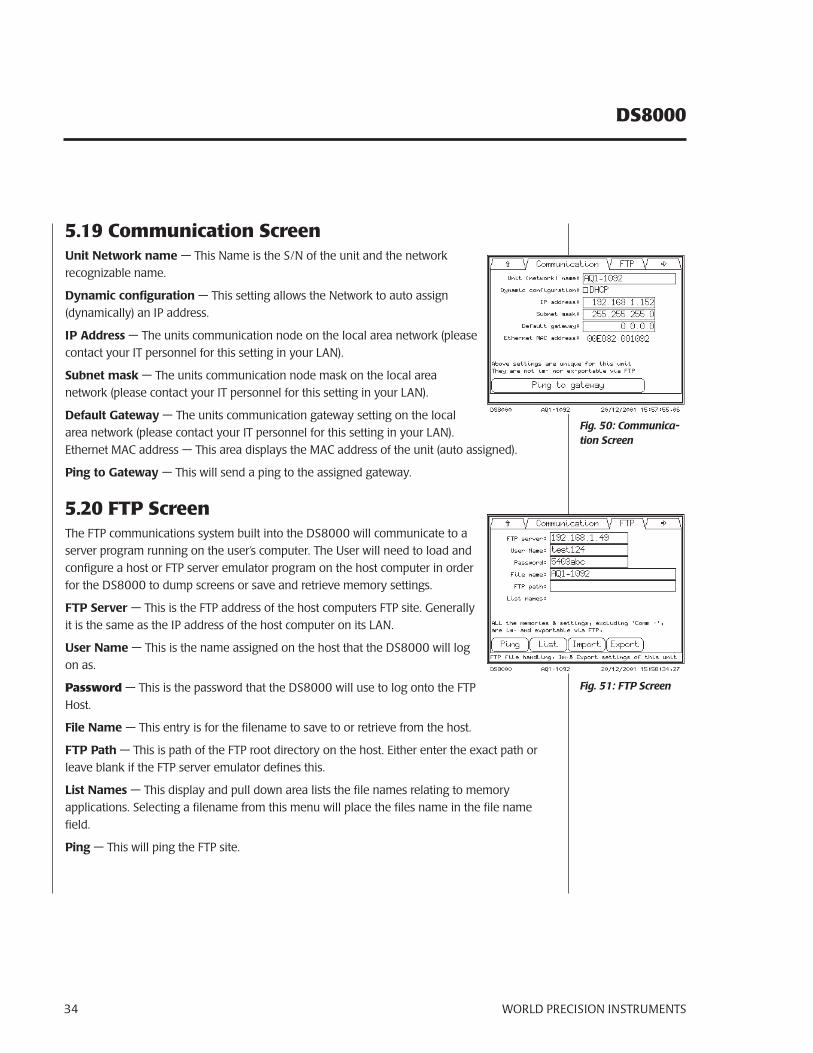
5.19 Communication ScreenUnit Network name — This Name is the S/N of the unit and the network recognizable name.
Dynamic configuration — This setting allows the Network to auto assign (dynamically) an IP address.
IP Address — The units communication node on the local area network (please contact your IT personnel for this setting in your LAN).
Subnet mask — The units communication node mask on the local area network (please contact your IT personnel for this setting in your LAN).
Default Gateway — The units communication gateway setting on the local area network (please contact your IT personnel for this setting in your LAN). Ethernet MAC address — This area displays the MAC address of the unit (auto assigned).
Ping to Gateway — This will send a ping to the assigned gateway.
5.20 FTP ScreenThe FTP communications system built into the DS8000 will communicate to a server program running on the user’s computer. The User will need to load and configure a host or FTP server emulator program on the host computer in order for the DS8000 to dump screens or save and retrieve memory settings.
FTP Server — This is the FTP address of the host computers FTP site. Generally it is the same as the IP address of the host computer on its LAN.
User Name — This is the name assigned on the host that the DS8000 will log on as.
Password — This is the password that the DS8000 will use to log onto the FTP Host.
File Name — This entry is for the filename to save to or retrieve from the host.
FTP Path — This is path of the FTP root directory on the host. Either enter the exact path or leave blank if the FTP server emulator defines this.
List Names — This display and pull down area lists the file names relating to memory applications. Selecting a filename from this menu will place the files name in the file name field.
Ping — This will ping the FTP site.
Fig. 51: FTP Screen
Fig. 50: Communica-tion Screen
WORLD PRECISION INSTRUMENTS 35
DS8000
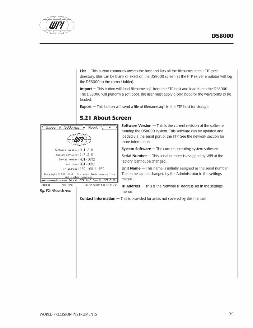
List — This button communicates to the host and lists all the filenames in the FTP path directory. (this can be blank or exact on the DS8000 screen as the FTP server emulator will log the DS8000 to the correct folder).
Import — This button will load filename.aq1 from the FTP host and load it into the DS8000. The DS8000 will perform a soft boot, the user must apply a cold boot for the waveforms to be loaded.
Export — This button will send a file of filename.aq1 to the FTP host for storage.
5.21 About ScreenSoftware Version — This is the current revision of the software running the DS8000 system. This software can be updated and loaded via the serial port of the FTP. See the network section for more information
System Software — The current operating system software.
Serial Number — This serial number is assigned by WPI at the factory (cannot be changed).
Unit Name — This name is initially assigned as the serial number. The name can be changed by the Administrator in the settings menus.
IP Address — This is the Network IP address set in the settings menus
Contact Information — This is provided for areas not covered by this manual.
Fig. 52: About Screen
DS8000
WORLD PRECISION INSTRUMENTS36
6.0 SERIAL & NETWORK COMMUNICATION
6.1 Network Hardware Setup
Fig. 55: Typical existing network with USB adapter
USB / Ethernet
switch / hub
host
DS8000
LAN
serial
host
DS8000
switch / hub
LAN
host
DS8000
switch / hub
USB / Ethernetadapter
USB
Fig. 53: Typical stand-alone network (optional USB)
Fig. 54: Typical existing network
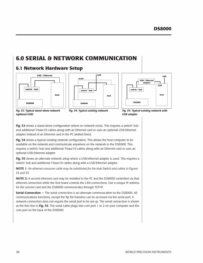
Fig. 53 shows a stand-alone configuration where no network exists. This requires a switch/ hub and additional T-base10 cables along with an Ethernet card or uses an optional USB/Ethernet adapter instead of an Ethernet card in the PC (dotted lines).
Fig. 54 shows a typical existing network configuration, This allows the host computer to be available on the network and communicate anywhere on the network to the DS8000. This requires a switch/ hub and additional T-base10 cables along with an Ethernet card or uses an optional USB/Ethernet adapter
Fig. 55 shows an alternate network setup where a USB/ethernet adapter is used. This requires a switch/ hub and additional T-base10 cables along with a USB/Ethernet adapter.
NOTE 1: An ethernet crossover cable may be substituted for the Hub/Switch and cables in Figures 53 and 55.
NOTE 2: A second ethernet card may be installed in the PC and the DS8000 controlled via that ethernet connection while the first board controls the LAN connections. Use a unique IP address for the second card and the DS8000 communicates through TCP/IP.
Serial Connection — The serial connection is an alternate communication to the DS8000. All communications functions, except the ftp file transfers can be accessed via the serial port. A network connection does not require the serial port to be set up. The serial connection is shown as the thin line in Fig. 54. The serial cable plugs into com port 1 or 2 on your computer and the com port on the back of the DS8000.
WORLD PRECISION INSTRUMENTS 37
DS8000
WARNING:
DO NOT PLUG THE DS8000 INTO AN EXISTING NETWORK LAN WITHOUT:
A. Being granted an IP address from your network administrator –or-
B. Receiving permission to use DHCP from your network administrator.
Most activities can be accomplished via the serial connections, except screen dumps and memory transfers.
For installations on a public network (DSL, cable, satellite, etc.) a router/hub with a firewall is required. WPI makes no claim or guarantee that the unit will work behind thirdparty LAN hardware.
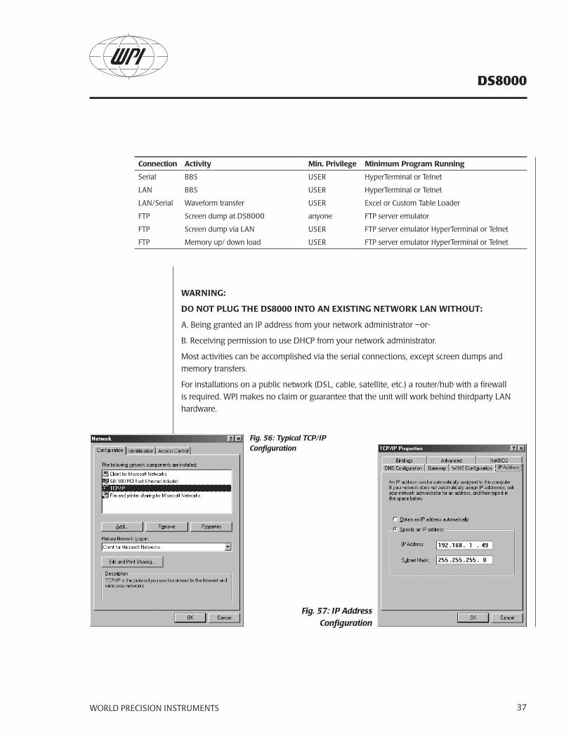
Fig. 57: IP Address Configuration
Fig. 56: Typical TCP/IP Configuration
Connection Activity Min. Privilege Minimum Program Running
Serial BBS USER HyperTerminal or Telnet
LAN BBS USER HyperTerminal or Telnet
LAN/Serial Waveform transfer USER Excel or Custom Table Loader
FTP Screen dump at DS8000 anyone FTP server emulator
FTP Screen dump via LAN USER FTP server emulator HyperTerminal or Telnet
FTP Memory up/ down load USER FTP server emulator HyperTerminal or Telnet
DS8000
WORLD PRECISION INSTRUMENTS38
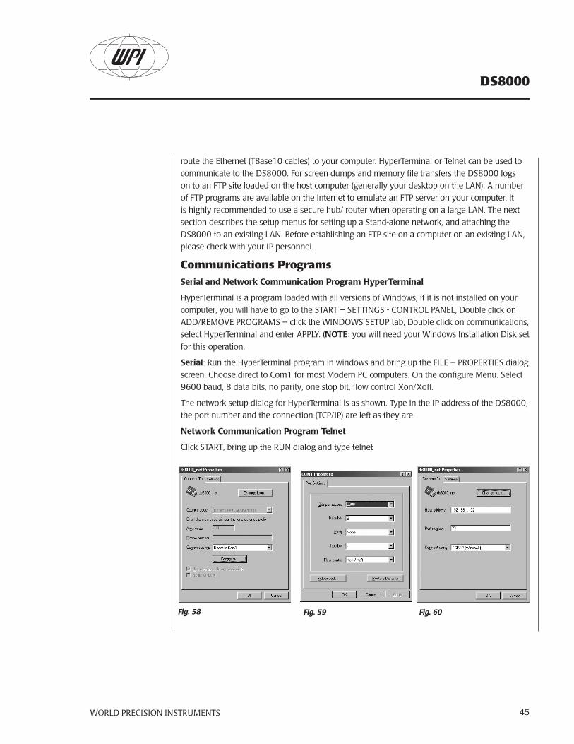
Serial Hardware Setup
Use a standard (not crossed) serial cable to connect to a personal computer (WPI part number 13555). The DS8000 Digital Stimulator uses the soft Xon/Xoff handshake method, the hardware handshake signals are not used to control the communication. Serial port settings are: RS232 (V24/V28), 9600 baud, 8 data bits, no parity, 1 stop bit. The program“Hyperterm.exe”, which is installed as a standard component of Windows™ can be used to evaluate the serial control.
6.2 Serial and Network ControlDS8000 User CommunicationType one <enter> to view the main menu.
The DS8000 will respond with this:
Current time: 02/01/2002 15:18:24
User name:
The normal login is USER with no password
Logon USER
Password <enter>
If an improper user/password is entered the DS8000 will respond with:
Access denied!
System name : AQ1-1092
IP address : 192.168.1.152
System version 1.7.2.0
Application version: 0.1.3.0
If the login is successful the DS8000 will respond with this:
Successful log in!
E : State TCP/IP connections
F : File transfer menu
P : Ping
Q : Quit (close this session)
<enter> : Repeat this screen
Main Menu: Type Your choice:
WORLD PRECISION INSTRUMENTS 39
DS8000
User Main Menu DefinitionsState TCP/IP connections – this entry will send out a string of characters
describing the Network information:
My address = 00E082 001092 192.168.1.152
mask = 255.255.255.0
router = 0.0.0.0
WinS = 0.0.0.0
time server = 0.0.0.0
line printer = 0.0.0.0
Listen FFFFFF FFFFFF 0.0.0.0 23 telnet -> 0
File Transfer Menu - The FTP transfer menu will respond this way with an FTP network setup:
FTP server: 192.168.1.49
FTP user: test124
FTP Path:
P: Ping to FTP server
S: Save screen as a bitmap (.bmp) file
Q: Quit (close the FTP menu)
User FTP Menu DefinitionsFTP server: 192.168.1.49 — This is the address of the FTP host computer.
FTP user: test124 — This is the user login the DS8000 will use to log into the host computer.
FTP Path: this is the sub-directory as specified by the FTP site in the host computer.
P: Ping to FTP server — Send an ICMP-ECHO or ping packet to the FTP server
with a time out of 1000 ms
S: Save screen as a bitmap (.bmp) file — This will save a graphics file to the FTP host computer at the location specified on the host computer via the host server emulator program.
Q: Quit — Close the FTP menu
NOTE: The Serial connection does not communicate with the FTP protocol directly through the serial cable, you must use network cabling. Ping to FTP, Software Update and Save Screen Dumps require the network connection.
DS8000
WORLD PRECISION INSTRUMENTS40
Ping — Type a “P” and the name or IP address of another network element to check the network at IP level. The maximum response time is 1000 ms.
Quit — logs the user out of this session.
DS8000 Owner CommunicationUser name: OWNER
Password: *****
Successful log in!
E: State TCP/IP connections
F: File transfer menu
K: Load custom amplitude list
L: Load custom waveform
P: Ping
Q: Quit (close this session)
<enter> : Repeat this screen
Main Menu: Type Your choice:
DS8000 Administrator CommunicationUser name: ADMINISTRATOR
Password: *****
A: Change Ethernet parameters
E: State TCP/IP connections
F: File transfer menu
K: Load custom amplitude list
L: Load custom wave form
P: Ping
Q: Quit (close this session)
<enter>: Repeat this screen
Main Menu: Type Your choice:
* See default Passwords at the end of this chapter.
WORLD PRECISION INSTRUMENTS 41
DS8000
DS8000 Administrator Menu DefinitionsA: Change Ethernet parameters — This menu will bring up a dialog for each Ethernet parameter:
Ethernet addr: 00E082 001092
IP address : 192.168.1.152 -> a
Subnet mask : 255.255.255.0 ->
IPA Router : 0.0.0.0 ->
Time to live or hops (def:50s): 50 ->
Retransmit time-out (600ms): 600 ->
Ack response delay (10ms): 20 ->
Disconnect time-out (5000ms): 5000 ->
Connection time-out (120000ms): 120000 ->
Transmit wait-time (50ms): 50 ->
Max. packet size (1024): 1024 ->
DHCP server resp. time(1000ms): 1000 ->
Unit name : AQ1-1092 ->
Password : test ->
MailServerIPA: * ->
FTP ServerIPA: 192.168.1.49 ->
FTP USER name: test124 ->
FTP Password : 5403abc ->
FTP Pathname : ->
FTP Filename : MCS_v1.0.0.6.frt ->
do I save and use these parameters Y / N ?
Change Ethernet Parameters Menu DefinitionsEthernet addr.: this is the fixed and world-wide unique MAC or Ethernet address of the unit.
Dynamic IP address: If you set the IP address to 0.0.0.0, then the unit requests the DHCP server for an IP address, subnet mask and router address. Then the unit registers its name on a WINS-server. So your computer can access the unit by IP address or name. If there is no WINS-server on your network, then the unit responds to the WINS broadcast of your computer and translates its name in his IP address.
DS8000
WORLD PRECISION INSTRUMENTS42
Fixed IP address: Ask your network manager for an IP address, Subnet mask, and router address and fill them in.
Time to live (TTL) or hops (def:50s): Once an internet packet is sent, every router will subtract one from this TTL; every second the TTL is also decreased by one. Once the TTL is zero or negative, the router will reject this.
Retransmit time-out: When a sent packet is not acknowledged in this time, then the unit will repeat this after 1, 3, 6, 10 times the retransmit time-out. If the packet is not acknowledged in 15 times the retransmit time-out, the connection is closed.
Ack response delay: A packet received is acknowledged after this delay, so the unit can send its answer to a question with the acknowledge.
Disconnect time-out: The channel remains closed for this time after a close of the connection.
Connection time-out: When the telnet session is unused for this time, the unit will close the connection.
Transmit wait-time: If the unit sends data, it will wait for this time to obtain well filled packets.
Max. packet size: If your network contains older components (bridges, switches, routers), it is possible that they are able to manage only smaller packets. In some network nodes with mini computers the max. packet size is 540.
DHCP server response time: This time must be higher than the maximum response time of the DHCP server or the maximum delay in your subnet.
Unit name: The network name of this unit. The maximum length of a network name is 15 characters.
Password: enter the log-on password name. Note that this password is case sensitive.
MailServerIPA: not used.
FTP ServerIPA: The name or IP address of the file server.
FTP USER name: The user account name of the DS8000
FTP Password: The user account password
FTP Pathname: The pad or map in your account that the unit will use: ex: c:\.
Filename: Default filename
Changes must be acknowledged with a “Y” stroke. Note that if network essential parameters are changed, the changes are stored in non volatile memory and the unit restarts. If you are connected to Ethernet, this connection will be closed on a restart.
NOTE: With the exception of IP address, IP subnet, FTP USER name, Unit name, Unit Password, FTP password, FTP pathname, the Administrator should leave these settings alone.
WORLD PRECISION INSTRUMENTS 43
DS8000
E: State TCP/IP connections — this entry will send out a string of characters describing the Network information:
My address = 00E082 001092 192.168.1.152
mask = 255.255.255.0
router = 0.0.0.0
WinS = 0.0.0.0
time server = 0.0.0.0
line printer = 0.0.0.0 Listen
FFFFFF FFFFFF 0.0.0.0 23 telnet -> 0
F: File transfer menu — This menu selection opens a submenu as above.
K: Load custom amplitude list — This is used by the custom waveform load
program.
L: Load custom waveform — This is used by the Excel transfer program.
P: Ping — Select this item and type in the IP address of the address you wish to ping.
Q: Quit — Close this session.
<enter> — Repeat this screen.
Software Update Loading (logged on as ADMINISTRATOR)The software up load uses the send text feature in HyperTerminal, select the transfer menu pull down and send text file selection. Choose the upload file, example MCS_v0.0.3.0.txt. The screen will respond with:
0 (XXXYYYZZZ software version 1.7.2.0 ) OK # 1 source ......................................….
When the program has uploaded completely the DS8000 will respond with a system restart.
NOTE: The default settings will be loaded over any settings in all four memories.
Login and Password InformationThe following lists the default login/ password combinations, please note the case of the entry.
DS8000
WORLD PRECISION INSTRUMENTS44
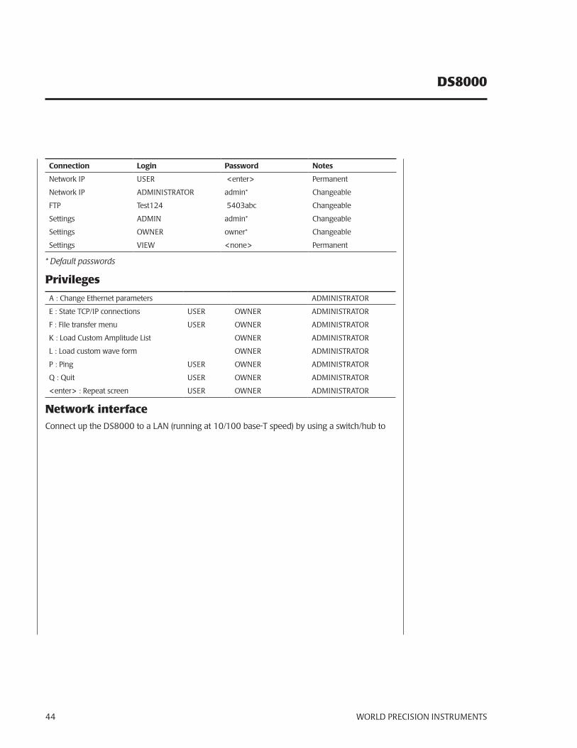
Connection Login Password Notes
Network IP USER <enter> Permanent
Network IP ADMINISTRATOR admin* Changeable
FTP Test124 5403abc Changeable
Settings ADMIN admin* Changeable
Settings OWNER owner* Changeable
Settings VIEW <none> Permanent
* Default passwords
Privileges
A : Change Ethernet parameters ADMINISTRATOR
E : State TCP/IP connections USER OWNER ADMINISTRATOR
F : File transfer menu USER OWNER ADMINISTRATOR
K : Load Custom Amplitude List OWNER ADMINISTRATOR
L : Load custom wave form OWNER ADMINISTRATOR
P : Ping USER OWNER ADMINISTRATOR
Q : Quit USER OWNER ADMINISTRATOR
<enter> : Repeat screen USER OWNER ADMINISTRATOR
Network interfaceConnect up the DS8000 to a LAN (running at 10/100 base-T speed) by using a switch/hub to
WORLD PRECISION INSTRUMENTS 45
DS8000
route the Ethernet (TBase10 cables) to your computer. HyperTerminal or Telnet can be used to communicate to the DS8000. For screen dumps and memory file transfers the DS8000 logs on to an FTP site loaded on the host computer (generally your desktop on the LAN). A number of FTP programs are available on the Internet to emulate an FTP server on your computer. It is highly recommended to use a secure hub/ router when operating on a large LAN. The next section describes the setup menus for setting up a Stand-alone network, and attaching the DS8000 to an existing LAN. Before establishing an FTP site on a computer on an existing LAN, please check with your IP personnel.
Communications ProgramsSerial and Network Communication Program HyperTerminal
HyperTerminal is a program loaded with all versions of Windows, if it is not installed on your computer, you will have to go to the START – SETTINGS - CONTROL PANEL, Double click on ADD/REMOVE PROGRAMS – click the WINDOWS SETUP tab, Double click on communications, select HyperTerminal and enter APPLY. (NOTE: you will need your Windows Installation Disk set for this operation.
Serial: Run the HyperTerminal program in windows and bring up the FILE – PROPERTIES dialog screen. Choose direct to Com1 for most Modern PC computers. On the configure Menu. Select 9600 baud, 8 data bits, no parity, one stop bit, flow control Xon/Xoff.
The network setup dialog for HyperTerminal is as shown. Type in the IP address of the DS8000, the port number and the connection (TCP/IP) are left as they are.
Network Communication Program Telnet
Click START, bring up the RUN dialog and type telnet
Fig. 58 Fig. 59 Fig. 60
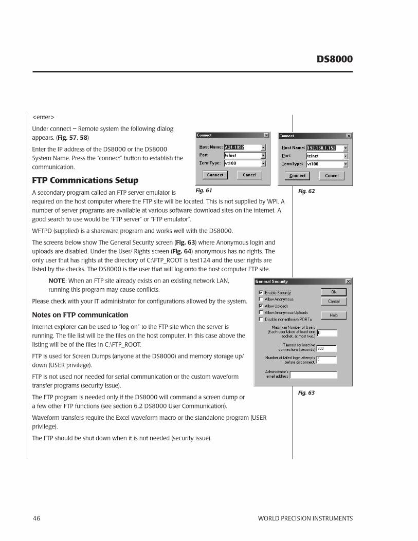
DS8000
WORLD PRECISION INSTRUMENTS46
<enter>
Under connect – Remote system the following dialog appears. (Fig. 57, 58)
Enter the IP address of the DS8000 or the DS8000 System Name. Press the “connect” button to establish the communication.
FTP Commnications SetupA secondary program called an FTP server emulator is required on the host computer where the FTP site will be located. This is not supplied by WPI. A number of server programs are available at various software download sites on the internet. A good search to use would be “FTP server” or “FTP emulator”.
WFTPD (supplied) is a shareware program and works well with the DS8000.
The screens below show The General Security screen (Fig. 63) where Anonymous login and uploads are disabled. Under the User/ Rights screen (Fig. 64) anonymous has no rights. The only user that has rights at the directory of C:\FTP_ROOT is test124 and the user rights are listed by the checks. The DS8000 is the user that will log onto the host computer FTP site.
NOTE: When an FTP site already exists on an existing network LAN, running this program may cause conflicts.
Please check with your IT administrator for configurations allowed by the system.
Notes on FTP communication
Internet explorer can be used to “log on” to the FTP site when the server is running. The file list will be the files on the host computer. In this case above the listing will be of the files in C:\FTP_ROOT.
FTP is used for Screen Dumps (anyone at the DS8000) and memory storage up/down (USER privilege).
FTP is not used nor needed for serial communication or the custom waveform transfer programs (security issue).
The FTP program is needed only if the DS8000 will command a screen dump or a few other FTP functions (see section 6.2 DS8000 User Communication).
Waveform transfers require the Excel waveform macro or the standalone program (USER privilege).
The FTP should be shut down when it is not needed (security issue).
Fig. 63
Fig. 61 Fig. 62
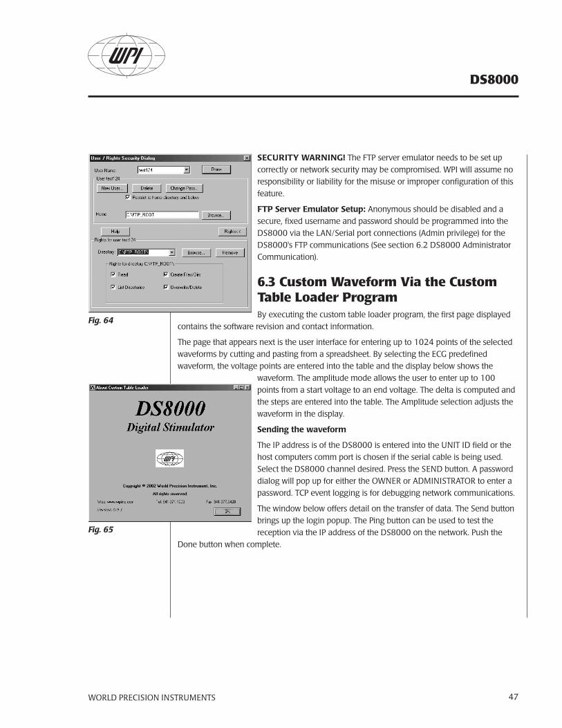
WORLD PRECISION INSTRUMENTS 47
DS8000
SECURITY WARNING! The FTP server emulator needs to be set up correctly or network security may be compromised. WPI will assume no responsibility or liability for the misuse or improper configuration of this feature.
FTP Server Emulator Setup: Anonymous should be disabled and a secure, fixed username and password should be programmed into the DS8000 via the LAN/Serial port connections (Admin privilege) for the DS8000's FTP communications (See section 6.2 DS8000 Administrator Communication).
6.3 Custom Waveform Via the Custom Table Loader ProgramBy executing the custom table loader program, the first page displayed
contains the software revision and contact information.
The page that appears next is the user interface for entering up to 1024 points of the selected waveforms by cutting and pasting from a spreadsheet. By selecting the ECG predefined waveform, the voltage points are entered into the table and the display below shows the
waveform. The amplitude mode allows the user to enter up to 100 points from a start voltage to an end voltage. The delta is computed and the steps are entered into the table. The Amplitude selection adjusts the waveform in the display.
Sending the waveform
The IP address is of the DS8000 is entered into the UNIT ID field or the host computers comm port is chosen if the serial cable is being used. Select the DS8000 channel desired. Press the SEND button. A password dialog will pop up for either the OWNER or ADMINISTRATOR to enter a password. TCP event logging is for debugging network communications.
The window below offers detail on the transfer of data. The Send button brings up the login popup. The Ping button can be used to test the reception via the IP address of the DS8000 on the network. Push the
Done button when complete.
Fig. 65
Fig. 64
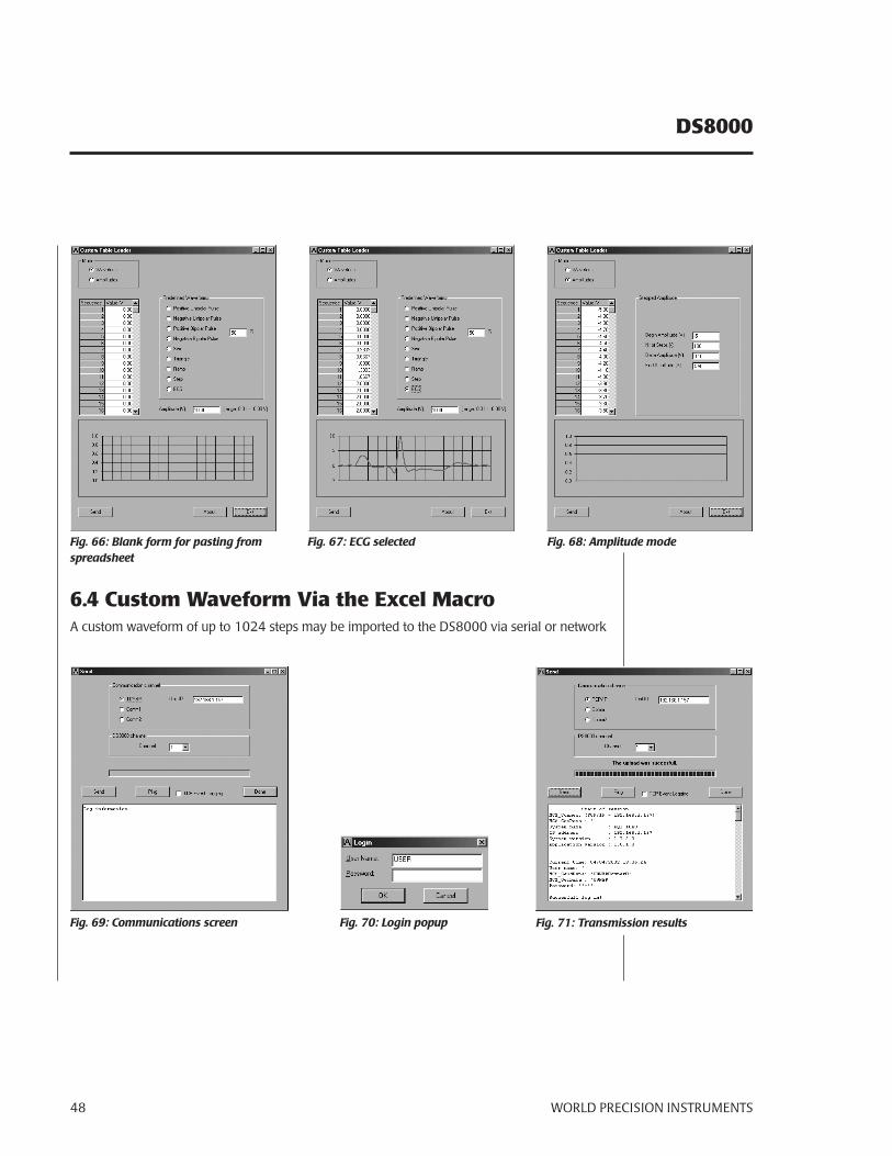
DS8000
WORLD PRECISION INSTRUMENTS48
6.4 Custom Waveform Via the Excel MacroA custom waveform of up to 1024 steps may be imported to the DS8000 via serial or network
Fig. 66: Blank form for pasting from spreadsheet
Fig. 67: ECG selected
Fig. 69: Communications screen Fig. 70: Login popup
Fig. 68: Amplitude mode
Fig. 71: Transmission results
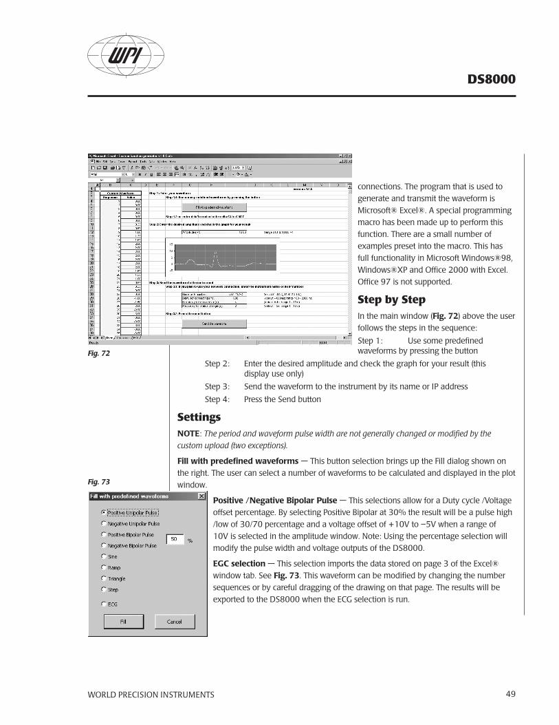
WORLD PRECISION INSTRUMENTS 49
DS8000
connections. The program that is used to generate and transmit the waveform is Microsoft® Excel®. A special programming macro has been made up to perform this function. There are a small number of examples preset into the macro. This has full functionality in Microsoft Windows®98, Windows®XP and Office 2000 with Excel. Office 97 is not supported.
Step by StepIn the main window (Fig. 72) above the user follows the steps in the sequence:
Step 1: Use some predefined waveforms by pressing the button
Step 2: Enter the desired amplitude and check the graph for your result (this display use only)
Step 3: Send the waveform to the instrument by its name or IP address
Step 4: Press the Send button
SettingsNOTE: The period and waveform pulse width are not generally changed or modified by the custom upload (two exceptions).
Fill with predefined waveforms — This button selection brings up the Fill dialog shown on the right. The user can select a number of waveforms to be calculated and displayed in the plot window.
Positive /Negative Bipolar Pulse — This selections allow for a Duty cycle /Voltage offset percentage. By selecting Positive Bipolar at 30% the result will be a pulse high /low of 30/70 percentage and a voltage offset of +10V to –5V when a range of 10V is selected in the amplitude window. Note: Using the percentage selection will modify the pulse width and voltage outputs of the DS8000.
EGC selection — This selection imports the data stored on page 3 of the Excel® window tab. See Fig. 73. This waveform can be modified by changing the number sequences or by careful dragging of the drawing on that page. The results will be exported to the DS8000 when the ECG selection is run.
Fig. 72
Fig. 73
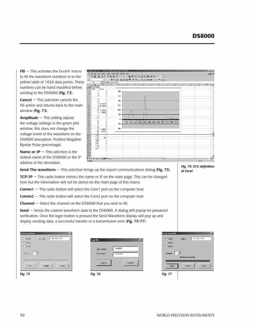
DS8000
WORLD PRECISION INSTRUMENTS50
Fill — This activates the Excel® macro to fill the waveform numbers in to the yellow table of 1024 data points. These numbers can be hand modified before sending to the DS8000 (Fig. 73).
Cancel — This selection cancels the Fill action and returns back to the main window (Fig. 73).
Amplitude — This setting adjusts the voltage settings in the green plot window, this does not change the voltage levels of the waveform on the DS8000 (exception: Positive/Negative Bipolar Pulse percentage).
Name or IP — This selection is the default name of the DS8000 or the IP address of the stimulator.
Send The waveform — This selection brings up the export communications dialog (Fig. 75).
TCP/IP — This radio button mimics the name or IP on the main page, This can be changed here but the information will not be stored on the main page of this macro.
Comm1 — This radio button will select the Com1 port on the computer host.
Comm2 — This radio button will select the Com2 port on the computer host
Channel — Select the channel on the DS8000 that you wish to fill.
Send — Sends the custom waveform data to the DS8000. A dialog will popup for password verification. Once the login button is pressed the Send Waveform display will pop up and display sending data, a successful transfer or a transmission error (Fig. 75-77).
Fig. 74: ECG definition in Excel
Fig. 77Fig. 75 Fig. 76
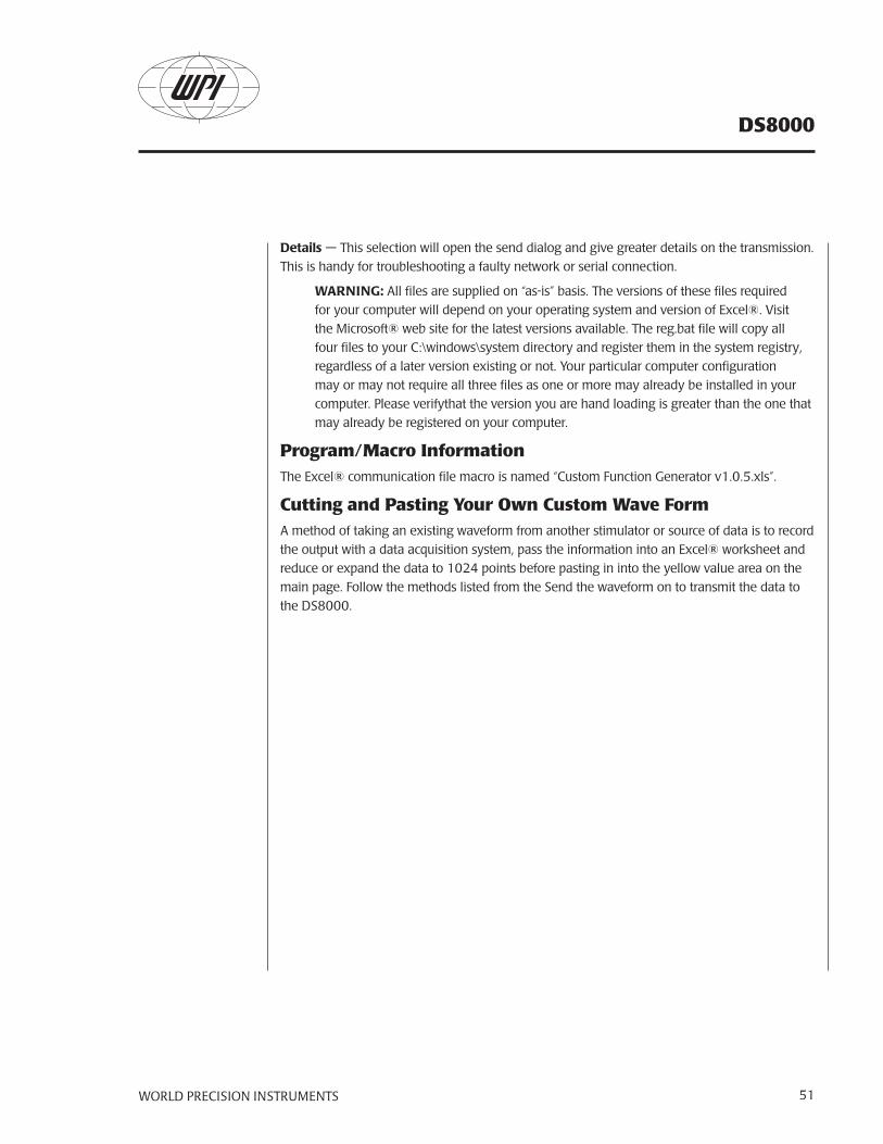
WORLD PRECISION INSTRUMENTS 51
DS8000
Details — This selection will open the send dialog and give greater details on the transmission. This is handy for troubleshooting a faulty network or serial connection.
WARNING: All files are supplied on “as-is” basis. The versions of these files required for your computer will depend on your operating system and version of Excel®. Visit the Microsoft® web site for the latest versions available. The reg.bat file will copy all four files to your C:\windows\system directory and register them in the system registry, regardless of a later version existing or not. Your particular computer configuration may or may not require all three files as one or more may already be installed in your computer. Please verifythat the version you are hand loading is greater than the one that may already be registered on your computer.
Program/Macro InformationThe Excel® communication file macro is named “Custom Function Generator v1.0.5.xls”.
Cutting and Pasting Your Own Custom Wave FormA method of taking an existing waveform from another stimulator or source of data is to record the output with a data acquisition system, pass the information into an Excel® worksheet and reduce or expand the data to 1024 points before pasting in into the yellow value area on the main page. Follow the methods listed from the Send the waveform on to transmit the data to the DS8000.
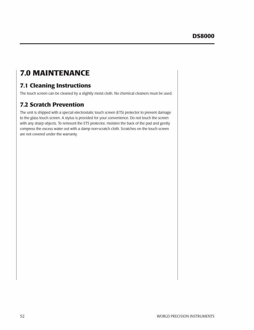
DS8000
WORLD PRECISION INSTRUMENTS52
7.0 MAINTENANCE
7.1 Cleaning InstructionsThe touch screen can be cleaned by a slightly moist cloth. No chemical cleaners must be used.
7.2 Scratch PreventionThe unit is shipped with a special electrostatic touch screen (ETS) protector to prevent damage to the glass touch screen. A stylus is provided for your convenience. Do not touch the screen with any sharp objects. To remount the ETS protector, moisten the back of the pad and gently compress the excess water out with a damp non-scratch cloth. Scratches on the touch screen are not covered under the warranty.
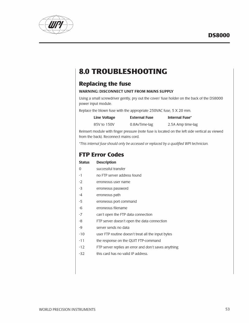
WORLD PRECISION INSTRUMENTS 53
DS8000
8.0 TROUBLESHOOTING
Replacing the fuseWARNING: DISCONNECT UNIT FROM MAINS SUPPLY
Using a small screwdriver gently, pry out the cover/ fuse holder on the back of the DS8000 power input module.
Replace the blown fuse with the appropriate 250VAC fuse, 5 X 20 mm.
Line Voltage External Fuse Internal Fuse*
85V to 150V 0.8AvTime-lag 2.5A Amp time-lag
Reinsert module with finger pressure (note fuse is located on the left side vertical as viewed from the back). Reconnect mains cord.
*This internal fuse should only be accessed or replaced by a qualified WPI technician.
FTP Error CodesStatus Description
0 successful transfer
-1 no FTP server address found
-2 erroneous user name
-3 erroneous password
-4 erroneous path
-5 erroneous port command
-6 erroneous filename
-7 can’t open the FTP data connection
-8 FTP server doesn’t open the data connection
-9 server sends no data
-10 user FTP routine doesn’t treat all the input bytes
-11 the response on the QUIT FTP-command
-12 FTP server replies an error and don’t saves anything
-32 this card has no valid IP address.
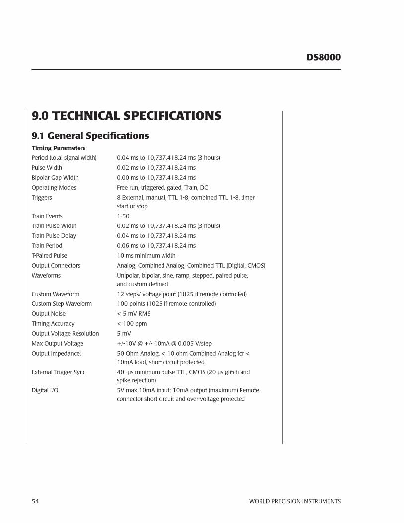
DS8000
WORLD PRECISION INSTRUMENTS54
9.0 TECHNICAL SPECIFICATIONS
9.1 General SpecificationsTiming Parameters
Period (total signal width) 0.04 ms to 10,737,418.24 ms (3 hours)
Pulse Width 0.02 ms to 10,737,418.24 ms
Bipolar Gap Width 0.00 ms to 10,737,418.24 ms
Operating Modes Free run, triggered, gated, Train, DC
Triggers 8 External, manual, TTL 1-8, combined TTL 1-8, timer start or stop
Train Events 1-50
Train Pulse Width 0.02 ms to 10,737,418.24 ms (3 hours)
Train Pulse Delay 0.04 ms to 10,737,418.24 ms
Train Period 0.06 ms to 10,737,418.24 ms
T-Paired Pulse 10 ms minimum width
Output Connectors Analog, Combined Analog, Combined TTL (Digital, CMOS)
Waveforms Unipolar, bipolar, sine, ramp, stepped, paired pulse, and custom defined
Custom Waveform 12 steps/ voltage point (1025 if remote controlled)
Custom Step Waveform 100 points (1025 if remote controlled)
Output Noise < 5 mV RMS
Timing Accuracy < 100 ppm
Output Voltage Resolution 5 mV
Max Output Voltage +/-10V @ +/- 10mA @ 0.005 V/step
Output Impedance: 50 Ohm Analog, < 10 ohm Combined Analog for < 10mA load, short circuit protected
External Trigger Sync 40 -μs minimum pulse TTL, CMOS (20 μs glitch and spike rejection)
Digital I/O 5V max 10mA input; 10mA output (maximum) Remote connector short circuit and over-voltage protected
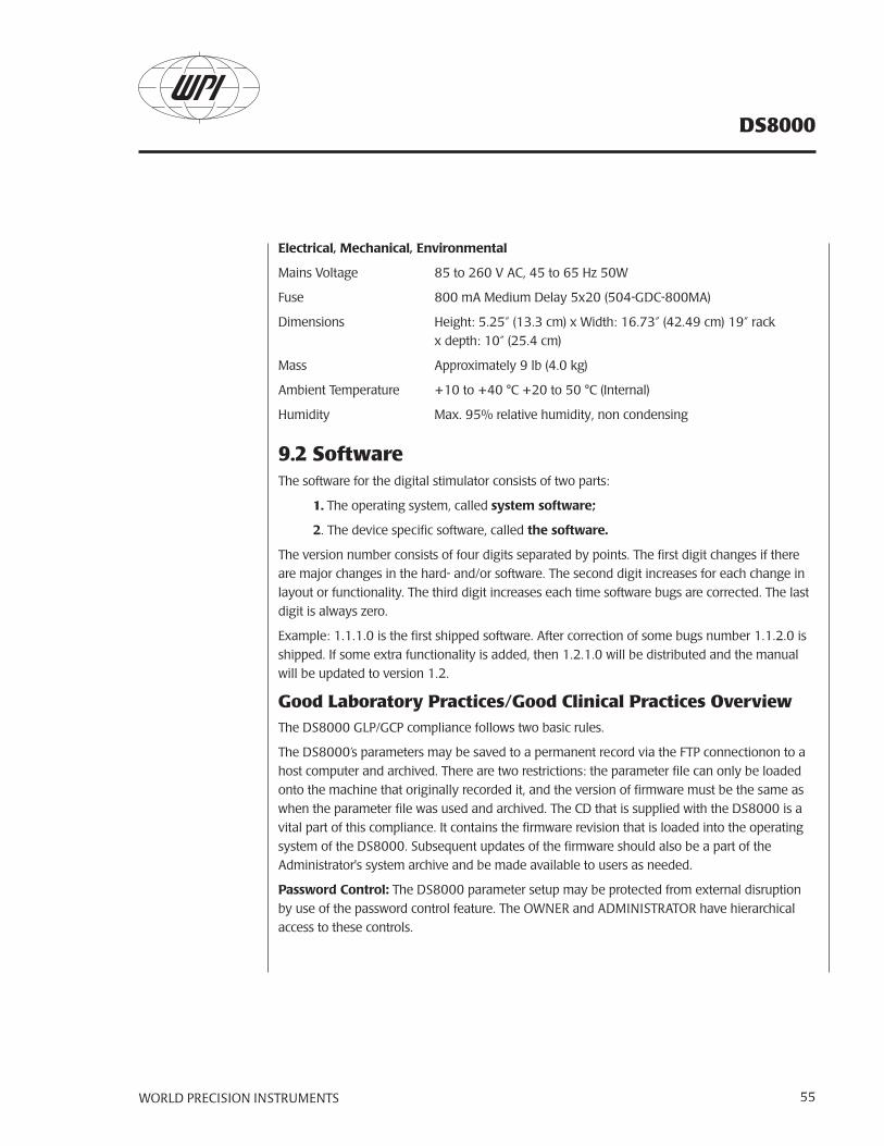
WORLD PRECISION INSTRUMENTS 55
DS8000
Electrical, Mechanical, Environmental
Mains Voltage 85 to 260 V AC, 45 to 65 Hz 50W
Fuse 800 mA Medium Delay 5x20 (504-GDC-800MA)
Dimensions Height: 5.25” (13.3 cm) x Width: 16.73” (42.49 cm) 19” rack x depth: 10” (25.4 cm)
Mass Approximately 9 lb (4.0 kg)
Ambient Temperature +10 to +40 °C +20 to 50 °C (Internal)
Humidity Max. 95% relative humidity, non condensing
9.2 SoftwareThe software for the digital stimulator consists of two parts:
1. The operating system, called system software;
2. The device specific software, called the software.
The version number consists of four digits separated by points. The first digit changes if there are major changes in the hard- and/or software. The second digit increases for each change in layout or functionality. The third digit increases each time software bugs are corrected. The last digit is always zero.
Example: 1.1.1.0 is the first shipped software. After correction of some bugs number 1.1.2.0 is shipped. If some extra functionality is added, then 1.2.1.0 will be distributed and the manual will be updated to version 1.2.
Good Laboratory Practices/Good Clinical Practices OverviewThe DS8000 GLP/GCP compliance follows two basic rules.
The DS8000’s parameters may be saved to a permanent record via the FTP connectionon to a host computer and archived. There are two restrictions: the parameter file can only be loaded onto the machine that originally recorded it, and the version of firmware must be the same as when the parameter file was used and archived. The CD that is supplied with the DS8000 is a vital part of this compliance. It contains the firmware revision that is loaded into the operating system of the DS8000. Subsequent updates of the firmware should also be a part of the Administrator's system archive and be made available to users as needed.
Password Control: The DS8000 parameter setup may be protected from external disruption by use of the password control feature. The OWNER and ADMINISTRATOR have hierarchical access to these controls.
DS8000
WORLD PRECISION INSTRUMENTS56
Memory Control: Within each parameter file are four memory locations that will reload all eight of the DS8000 channel setups.
USER Rights
The USER may upload and/or download to the host computer via FTP on the Ethernet connection for storage of the parameter file. The USER may load the DS8000 from a stored memory, but not save one.
OWNER Rights
The OWNER may upload or download parameter files to the host computer. The OWNER may recall or store a memory location by entering a password at the settings menu.
ADMINISTRATOR Rights
The ADMINISTRATOR may upload or download parameter files to the host computer. The ADMINISTRATOR may recall or store memory by entering a password at the settings menu.
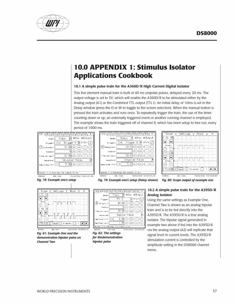
WORLD PRECISION INSTRUMENTS 57
DS8000
10.0 APPENDIX 1: Stimulus Isolator Applications Cookbook10.1 A simple pulse train for the A360D/R High Current Digital Isolator
This five element manual train is built of 40 ms unipolar pulses, delayed every 20 ms. The output voltage is set to 5V, which will enable the A360D/R to be stimulated either by the Analog output (A1) or the Combined TTL output (TTL1). An initial delay of 10ms is set in the Delay window (press the D or W to toggle to the screen selection). When the manual button is pressed the train activates and runs once. To repeatedly trigger the train, the use of the timer counting down or up, an externally triggered event or another running channel is employed. The example shows the train triggered off of channel 8, which has been setup to free run, every period of 1000 ms.
Fig. 78: Example one’s setup Fig. 79: Example one’s setup (Delay shown) Fig. 80: Scope output of example one
10.2 A simple pulse train for the A395D/R Analog IsolatorUsing the same settings as Example One, Channel Two is shown as an analog bipolar train and is to be fed directly into the A395D/R. The A395D/R is a true analog isolator. The bipolar signal generated in example two above if fed into the A395D/R via the analog output (A2) will replicate that signal level in current levels. The A395D/R stimulation current is controlled by the amplitude setting in the DS8000 channel menu.
Fig. 82: The settings for thedemonstration bipolar pulse
Fig. 81: Example One and the demonstration bipolar pulse on Channel Two
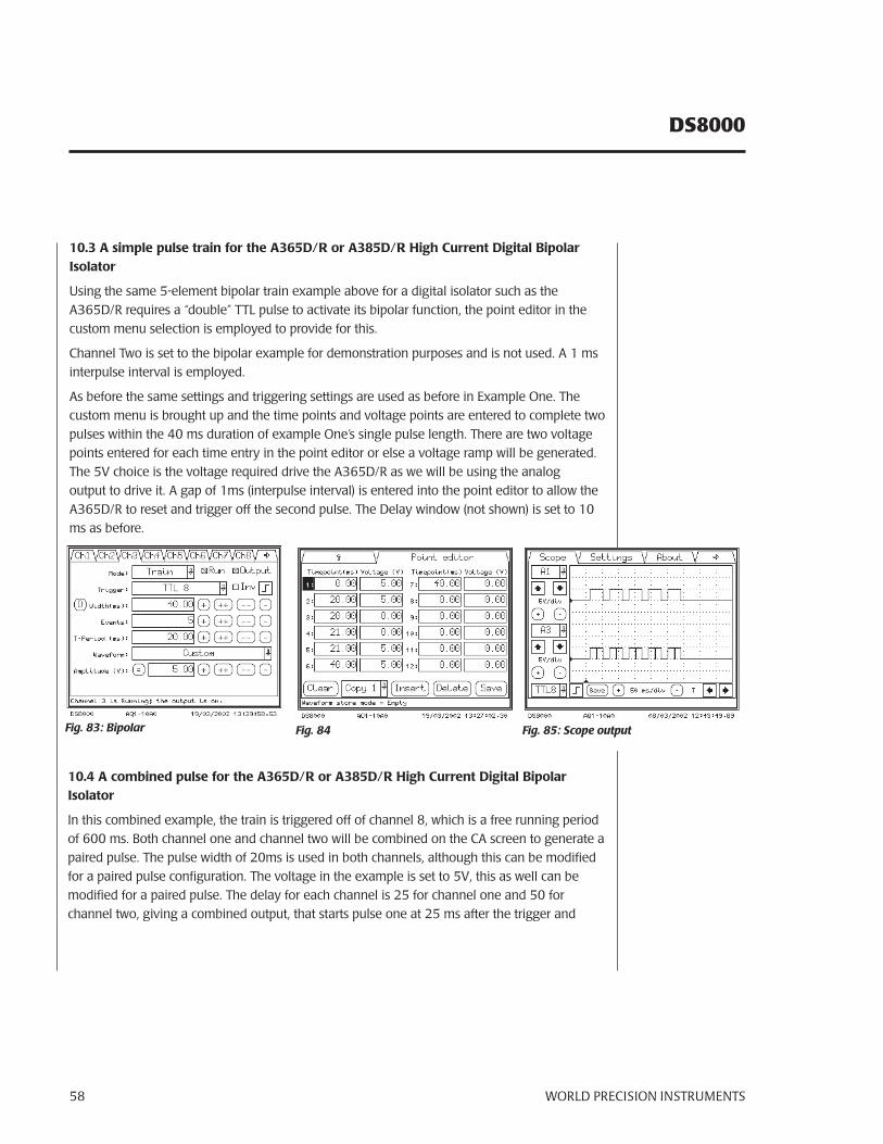
DS8000
WORLD PRECISION INSTRUMENTS58
10.3 A simple pulse train for the A365D/R or A385D/R High Current Digital Bipolar Isolator
Using the same 5-element bipolar train example above for a digital isolator such as the A365D/R requires a “double” TTL pulse to activate its bipolar function, the point editor in the custom menu selection is employed to provide for this.
Channel Two is set to the bipolar example for demonstration purposes and is not used. A 1 ms interpulse interval is employed.
As before the same settings and triggering settings are used as before in Example One. The custom menu is brought up and the time points and voltage points are entered to complete two pulses within the 40 ms duration of example One’s single pulse length. There are two voltage points entered for each time entry in the point editor or else a voltage ramp will be generated. The 5V choice is the voltage required drive the A365D/R as we will be using the analog output to drive it. A gap of 1ms (interpulse interval) is entered into the point editor to allow the A365D/R to reset and trigger off the second pulse. The Delay window (not shown) is set to 10 ms as before.
Fig. 83: Bipolar Fig. 84
10.4 A combined pulse for the A365D/R or A385D/R High Current Digital Bipolar Isolator
In this combined example, the train is triggered off of channel 8, which is a free running period of 600 ms. Both channel one and channel two will be combined on the CA screen to generate a paired pulse. The pulse width of 20ms is used in both channels, although this can be modified for a paired pulse configuration. The voltage in the example is set to 5V, this as well can be modified for a paired pulse. The delay for each channel is 25 for channel one and 50 for channel two, giving a combined output, that starts pulse one at 25 ms after the trigger and
Fig. 85: Scope output
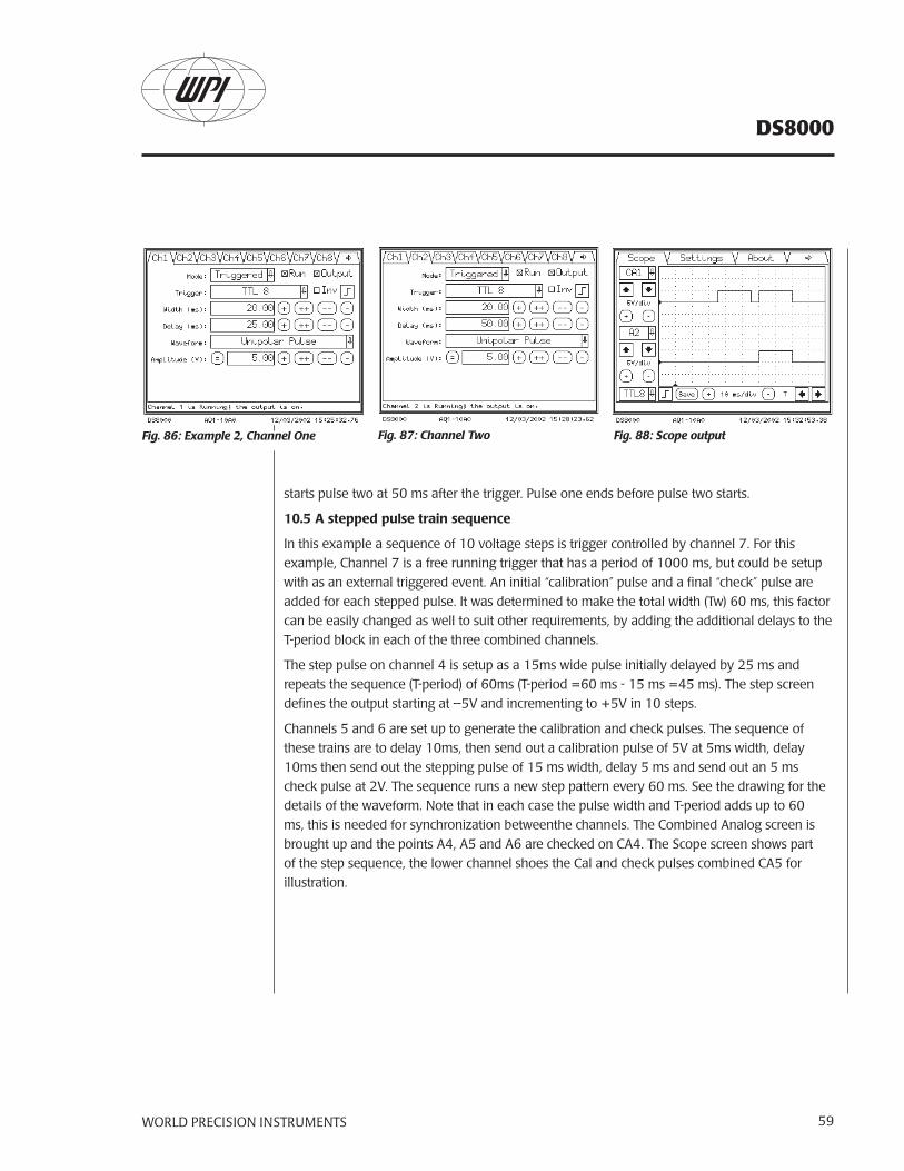
WORLD PRECISION INSTRUMENTS 59
DS8000
starts pulse two at 50 ms after the trigger. Pulse one ends before pulse two starts.
10.5 A stepped pulse train sequence
In this example a sequence of 10 voltage steps is trigger controlled by channel 7. For this example, Channel 7 is a free running trigger that has a period of 1000 ms, but could be setup with as an external triggered event. An initial “calibration” pulse and a final “check” pulse are added for each stepped pulse. It was determined to make the total width (Tw) 60 ms, this factor can be easily changed as well to suit other requirements, by adding the additional delays to the T-period block in each of the three combined channels.
The step pulse on channel 4 is setup as a 15ms wide pulse initially delayed by 25 ms and repeats the sequence (T-period) of 60ms (T-period =60 ms - 15 ms =45 ms). The step screen defines the output starting at –5V and incrementing to +5V in 10 steps.
Channels 5 and 6 are set up to generate the calibration and check pulses. The sequence of these trains are to delay 10ms, then send out a calibration pulse of 5V at 5ms width, delay 10ms then send out the stepping pulse of 15 ms width, delay 5 ms and send out an 5 ms check pulse at 2V. The sequence runs a new step pattern every 60 ms. See the drawing for the details of the waveform. Note that in each case the pulse width and T-period adds up to 60 ms, this is needed for synchronization betweenthe channels. The Combined Analog screen is brought up and the points A4, A5 and A6 are checked on CA4. The Scope screen shows part of the step sequence, the lower channel shoes the Cal and check pulses combined CA5 for illustration.
Fig. 86: Example 2, Channel One Fig. 87: Channel Two Fig. 88: Scope output
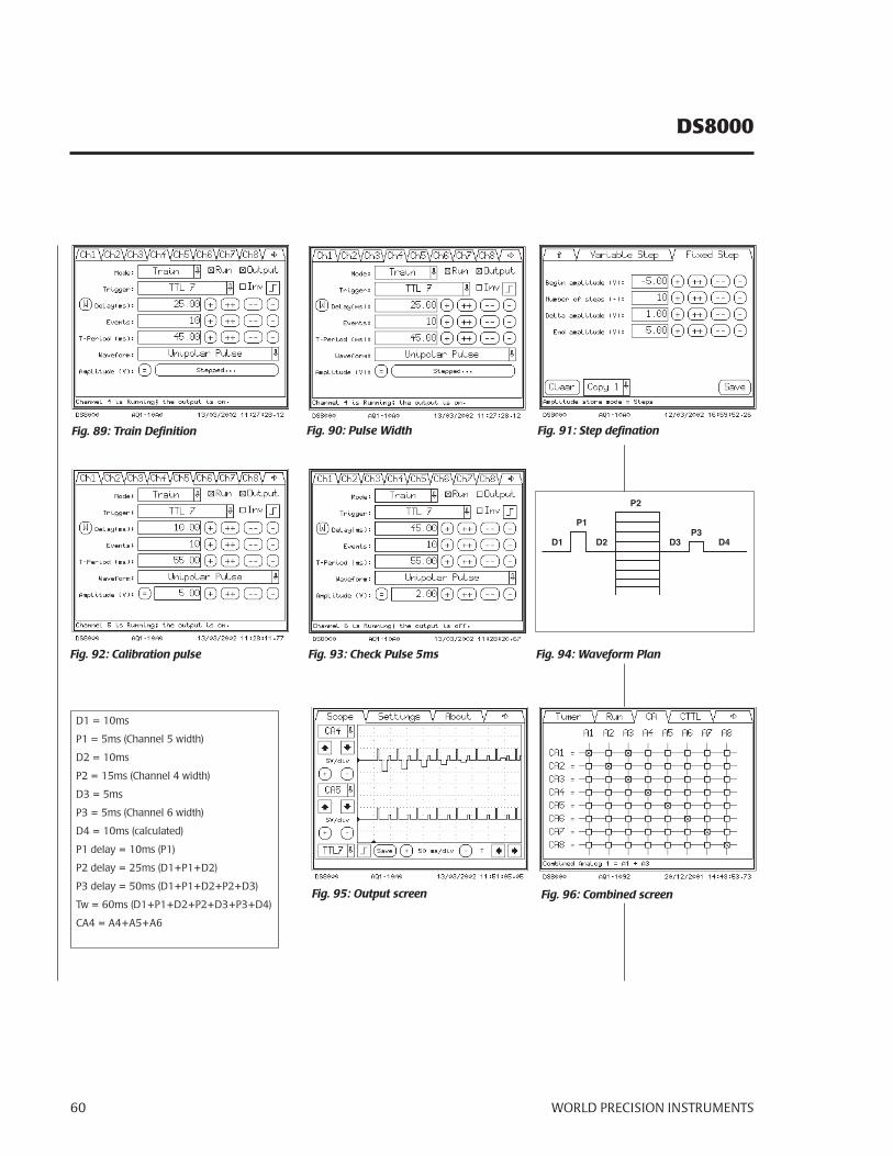
DS8000
WORLD PRECISION INSTRUMENTS60
Fig. 89: Train Definition
D1 = 10ms
P1 = 5ms (Channel 5 width)
D2 = 10ms
P2 = 15ms (Channel 4 width)
D3 = 5ms
P3 = 5ms (Channel 6 width)
D4 = 10ms (calculated)
P1 delay = 10ms (P1)
P2 delay = 25ms (D1+P1+D2)
P3 delay = 50ms (D1+P1+D2+P2+D3)
Tw = 60ms (D1+P1+D2+P2+D3+P3+D4)
CA4 = A4+A5+A6
Fig. 90: Pulse Width Fig. 91: Step defination
Fig. 92: Calibration pulse Fig. 93: Check Pulse 5ms
Fig. 95: Output screen Fig. 96: Combined screen
D1P3
P2
P1
D4D3D2
Fig. 94: Waveform Plan
WORLD PRECISION INSTRUMENTS 61
DS8000
11.0 APPENDIX 2: Example Bioresearch Application (Drug Injection/Perfusion System)An example outline of stimulation, drug injection and perfusion control.
Total of one single perfusion cycle = 5 minutes (300,000 ms).
Define channel 8 as the master control channel.
Start this channel manually or by External start pulse via computer Data acquisition system control.
Define channel 7 as the perfusion fill control channel.
Fill at time zero (10 ms after start), TTL command to perfusion fill
Define channel 6 as the perfusion empty control channel.
Empty at 4:30 minutes (270,000 ms), TTL command to perfusion empty.
Define channel 5 as the drug control channel.
Inject drugs at 2 minutes (120,000 ms) TTL command to Syringe pump start.
Define channels 1-4 as the stimulation channels.
Stimulation for 1 minute (60,000 ms).
DS8000
WORLD PRECISION INSTRUMENTS62
WORLD PRECISION INSTRUMENTS 63
DS8000
WarrantyWPI (World Precision Instruments, Inc.) warrants to the original purchaser that this equipment, including its components and parts, shall be free from defects in material and workmanship for a period of one year* from the date of receipt. WPI’s obligation under this warranty shall be limited to repair or replacement, at WPI’s option, of the equipment or defective components or parts upon receipt thereof f.o.b. WPI, Sarasota, Florida U.S.A. Return of a repaired instrument shall be f.o.b. Sarasota.
The above warranty is contingent upon normal usage and does not cover products which have been modified without WPI’s approval or which have been subjected to unusual physical or electrical stress or on which the original identification marks have been removed or altered. The above warranty will not apply if adjustment, repair or parts replacement is required because of accident, neglect, misuse, failure of electric power, air conditioning, humidity control, or causes other than normal and ordinary usage.
To the extent that any of its equipment is furnished by a manufacturer other than WPI, the foregoing warranty shall be applicable only to the extent of the warranty furnished by such other manufacturer. This warranty will not apply to appearance terms, such as knobs, handles, dials or the like.
WPI makes no warranty of any kind, express or implied or statutory, including without limitation any warranties of merchantability and/or fitness for a particular purpose. WPI shall not be liable for any damages, whether direct, indirect, special or consequential arising from a failure of this product to operate in the manner desired by the user. WPI shall not be liable for any damage to data or property that may be caused directly or indirectly by use of this product.
Claims and Returns• Inspect all shipments upon receipt. Missing cartons or obvious damage to cartons should be noted on the delivery receipt before signing. Concealed loss or damage should be reported at once to the carrier and an inspection requested. All claims for shortage or damage must be made within 10 days after receipt of shipment. Claims for lost shipments must be made within 30 days of invoice or other notification of shipment. Please save damaged or pilfered cartons until claim settles. In some instances, photographic documentation may be required. Some items are time sensitive; WPI assumes no extended warranty or any liability for use beyond the date specified on the container.
• WPI cannot be held responsible for items damaged in shipment en route to us. Please enclose merchandise in its original shipping container to avoid damage from handling. We recommend that you insure merchandise when shipping. The customer is responsible for paying shipping expenses including adequate insurance on all items returned.
• Do not return any goods to WPI without obtaining prior approval and instructions (RMA#) from our returns department. Goods returned unauthorized or by collect freight may be refused. The RMA# must be clearly displayed on the outside of the box, or the package will not be accepted. Please contact the RMA department for a request form.
• Goods returned for repair must be reasonably clean and free of hazardous materials.
• A handling fee is charged for goods returned for exchange or credit. This fee may add up to 25% of the sale price depending on the condition of the item. Goods ordered in error are also subject to the handling fee.
• Equipment which was built as a special order cannot be returned.
• Always refer to the RMA# when contacting WPI to obtain a status of your returned item.
• For any other issues regarding a claim or return, please contact the RMA department
Warning: This equipment is not designed or intended for use on humans.
* Electrodes, batteries and other consumable parts are warranted for 30 days only from the date on which the customer receives these items.
World Precision Instruments, Inc.International Trade Center, 175 Sarasota Center Blvd., Sarasota FL 34240-9258Tel: 941-371-1003 • Fax: 941-377-5428 • E-mail: [email protected]: Astonbury Farm Business Centre • Aston, Stevenage, Hertfordshire SG2 7EG • Tel: 01438-880025 • Fax: 01438-880026 • E-mail: [email protected]: Liegnitzer Str. 15, D-10999 Berlin • Tel: 030-6188845 • Fax: 030-6188670 • E-mail: [email protected]


![Spatiotemporal Bundle Adjustment for Dynamic 3D …...personal cameras, i.e., smartphones, consumer camcorders, or egocentric cameras, are simultaneously triggered [10]. Thus, in the](https://img.pdfslide.net/doc/110x75/5fe7fb30ff9bc64ea27f7157/spatiotemporal-bundle-adjustment-for-dynamic-3d-personal-cameras-ie-smartphones.jpg)