Embed Size (px)
Citation preview
8041
p. 1/9www.burkert.com
Technical data
General data
Compatibility with fittings S020 (see corresp. datasheet)
Materials
Housing, cover, nut PVDF sensor version
Stainless steel sensor version Screws / Seal / Cable glandsWetted parts materials Sensor holder
ElectrodesSeals
Earth ring (PVDF sensor version)
Electrode holder (St. Steel sensor version)
PC (glass fibre reinforced for housing)
PPA (glass fibre reinforced)
Stainless steel / NBR / PA with neoprene seal
PVDF or Stainless steel 1.4404/316LStainless steel 1.4404/316LG2” connection: FKM or EPDM (conform to FDA),Clamp connection: EPDM or FEP (to be ordered separately)
Stainless steel 1.4404/316LPEEK (conform to FDA)
Surface finishing quality Ra < 0.8 m (Clamp connection)
Electrical connections 2 cable glands M20 x 1.5
Recommended cable 0.5...1.5 mm2 cross-section, shielded cable,6...12 mm diameter (if only one cable is used per cable gland) or 4 mm diameter (if two cables are used per cable gland with using the
supplied multi-way seal)
Environment
Ambient temperature -10...+60°C (+14...+140°F) (operating)
-20...+60°C (-4...+140°F) (storage)
Relative humidity < 80%, without condensation
Height above sea level Max. 2000 m
Insertion electromagnetic flowmeter
Type S020
INSERTION
T-fitting
Type 8025
Universal transmitter/
batch controller (remote version)
• Sensor without moving parts
• Flowmeter with On/Off control
• Application related calibration by Teach-In
• Clean in place (CIP)
• FDA conform materials
PLC
Type 8041 can be combined with...
Type 8802-GD
TopControl System
Type 8644
Valve islands with
electronic I/O
The electromagnetic flowmeter 8041 is made
up of an electronic module and a sensor using
PVDF or stainless steel material. It has been
designed to measure a flow rate of neutral and
slightly aggressive fluids with a conductivity of
more than 20 µS/cm in DN06...DN400 pipes.
It is fitted with a 4...20 mA output, a pulse
output and a relay output. The different pa-
rameters can be set by means of 5 switches, a
push-button and a 10 fields LED bargraph.
It is available:
- with G2” connection for the version with a
PVDF sensor
- with G2” or clamp connection for the version
with a stainless steel sensor.
The version with a stainless steel sensor can
be used in applications with higher pressures
(PN16) and higher temperatures (150°C)
Type 8619
multiCELL
Transmitter/Controller
8041
p. 2/9
* For the 2014/68/EU pressure directive, the device can only be used under following conditions (depending on max. pressure, pipe diameter and fluid).
Type of fluid Conditions
Fluid group 1,
article 4, §1.c.i Forbidden
Fluid group 2,
article 4, §1.c.i
DN 32 orPN*DN 1000
Fluid group 1,
article 4, §1.c.ii
DN 25 orPN*DN 2000
Fluid group 2,
article 4, §1.c.ii
DN 200 orPN 10 orPN*DN 5000
Complete device data (Fitting S020 + flowmeter)
Pipe diameter
G2” connectionClamp connection
DN06...DN400DN32...DN100
Measuring range 0.2...10 m/s
Sensor element Electrodes
Fluid temperature
PVDF sensor versionStainless steel sensor version
see Pressure/Temperature diagram0...+80°C (+32...+176°F) (depends on fitting)
-15...+150°C (+5...+302°F) (depends on fitting)
Fluid pressure max.
PVDF sensor versionStainless steel sensor version
see pressure/temperature diagramPN10 (145.1 PSI)
PN10 (145.1 PSI) (with plastic fitting) - PN16 (232.16 PSI) (with metal fitting)
Conductivity min. 20 S/cmViscosity < 1000 mPa.s
Measurement deviation1)
Teach-InStandard K-factor
±0.5% of Reading2) (at the teach flow rate value)
±3.5% of Reading2)
Linearity ±0.5% of F.S.*)2)
Repeatability ±0.25% of Reading2)
1) =“measurement bias” as defined in the standard JCGM 200:20122) Under reference conditions i.e. measuring fluid=water, ambient and water temperature = 20°C (68°F), applying the minimum inlet and outlet pipe straights, matched inside pipe dimensions.
* F.S.= Full scale (10 m/s)
Electrical data
Power supply 18...36 V DC filtered and regulated (3 wires)
Reversed polarity of DC protected
Current consumption 220 mA (at 18 V DC)
Output
Signal current
Frequency
Relay
4...20 mA (sink or source by wiring), 100 ms refresh time;max. loop impedance: 1100 at 36 V DC;330 at 18 V DC0...240 Hz, duty cycle = 50%±1%; 100 mA max.,protected against short-circuits and polarity reversals.Normally open or normally closed (depending on wiring), 250 V AC/3 A or 40 V DC/3 A (resistive load)
4...20 mA output uncertainty ±1%
Alarm
Full scale exceedingFault signalling
22 mA and 256 Hz22 mA and 0 Hz
User parameter Saved in EEPROM
Specific technical data of UL-recognized products for US and Canada
Relay output 30 V AC and 42 V peak max./3A or 60 V DC max./1 A
Ambient temperature 0...+40°C (32...+104°F)
Relative humidity max. 80%, without condensation
Intended for an inner pollution Pollution degree 2
Installation category Category I
Standards, directives and certifications
Protection class IP65
Standard and directives
Pressure
The applied standards, which verify conformity with the EU Directives, can be found on the EU Type Examination Certifi-cate and/or the EU Declaration of conformity (if applicable)
Complying with article 4, §1 of 2014/68/EU directive*
Certificates
FDA declaration of conformityECR1935/2004 declaration
For stainless steel or PVDF sensor with FKM or EPDM seal
Only for stainless steel sensor with EPDM seal
Certification
UL-Recognized for US and Canada UL61010-1 + CAN/CSA-C22.2 No.61010-1
8041
p. 3/9
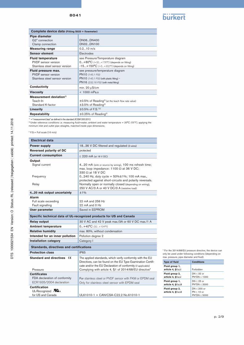
Pressure/Temperature diagram
Please be aware of the fluid pressure/temperature dependence according to the respective fitting+flowmeter material as shown in the diagrams.
8041 with a PVDF sensor
(depending on the fitting material)
8041 with a stainless steel sensor
(depending on the fitting material)
+10 +30 +50 +70 0
2
1
3
4
5
6
7
A
8
9
10
Pressure
(Bar)
Temperature
(°C)
PVDF (PN10) / Metal
PVC + PP
PVC (PN10)
PP (PN10)
Pressure
(Bar)
Temperature
(°C)
10 9 8 7 6 5 4 3 2 1 0
-10 +10 +30 +50 +70 +90 +110 +130
16 15 14 13 12 11
+150
A
PVC + PP
PVDF
PVC (PN10)
PP (PN10)
Metal (PN16)
PVDF (PN10)
A: Application range for complete device (fitting + flowmeter)
Main features and programming Possible applications
Using as a flowmeter
• Programming of the full scale
- selection of a predefined measuring range: 0...2, 0...5 or 0...10 m/s
- selection by Teach-In: with the actual max. flow velocity of the applica-
tion
• 4...20 mA current output
• 0...240 Hz frequency output
• Relay output: switching mode either window or hysteresis, on low or
high switching threshold
• Relay Time delay before switching
• Filter
• Alarm:
- for full scale exceeding with 22 mA and 256 Hz
- for fault signalling with 22 mA and 0 Hz
Using as an ON/OFF control
• Flow detection with switching thresholds, defined as a percentage of
max. flow rate.
• Adjustment of the full scale of the device accordingly to the customer
process full scale.
Flow control of conductive fluids, contaminated or not:
Waste water treatment
Flow control of drinking water
Laundries: measurement and control of the water consumption
Swimming pools: pump protection and flow control
Food-processing industry: monitoring of the cleaning cycles (conform to
FDA)
Irrigation
Design
The E-shaped magnetic system in-
side the sensor induces a magnetic
field into the fluid, which is perpen-
dicular to the direction of flow. Two
electrodes are in galvanic contact
with the liquid.
Based on the Faraday law a voltage can be measured between these
electrodes once a liquid (min. conductivity of 20 µS/cm) flows along the pipe.
This voltage is proportional to the flow velocity.
Using the K-factor for the individual pipe diameter the speed of flow is
converted into volume per time.
8041
p. 4/9
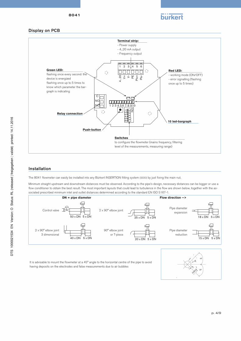
Display on PCB
1 2 3 4 5 6
4...2
0
V+
V
- P
E
Pls
+
Pls
-
ON
1 2 3 4 5 6
1 2 3 4 5 6 7 8 9 10
C
NO
NC
Red LED:
- working mode (ON/OFF)
- error signalling (flashing
once up to 5 times)
Green LED:
flashing once every second: the
device is energized
flashing once up to 5 times to
know which parameter the bar-
graph is indicating
Terminal strip:
- Power supply
- 4...20 mA output
- Frequency output
10 led-bargraph
Push-button
Relay connection
Switches
to configure the flowmeter (mains frequency, filtering
level of the measurements, measuring range)
Installation
The 8041 flowmeter can easily be installed into any Bürkert INSERTION fitting system (S020) by just fixing the main nut.
Minimum straight upstream and downstream distances must be observed. According to the pipe’s design, necessary distances can be bigger or use a
flow conditioner to obtain the best result. The most important layouts that could lead to turbulence in the flow are shown below, together with the as-
sociated prescribed minimum inlet and outlet distances determined according to the standard EN ISO 5167-1.
DN = pipe diameter Flow direction -->
Control valve 2 x 90° elbow jointPipe diameter
expansion
2 x 90° elbow joint
3 dimensional
90° elbow joint
or T-piece
Pipe diameter
reduction
It is advisable to mount the flowmeter at a 45° angle to the horizontal centre of the pipe to avoid
having deposits on the electrodes and false measurements due to air bubbles
.
8041
p. 5/9
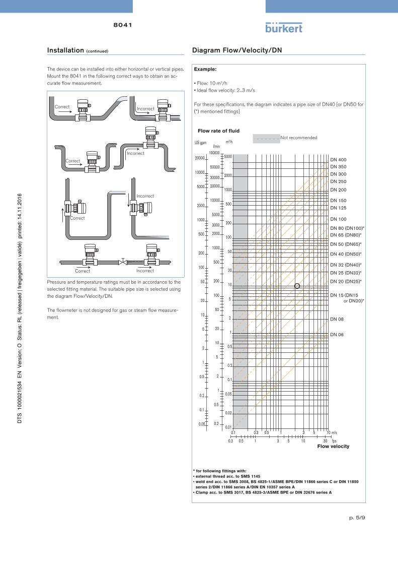
Installation (continued) Diagram Flow/Velocity/DN
The device can be installed into either horizontal or vertical pipes.
Mount the 8041 in the following correct ways to obtain an ac-
curate flow measurement.
Example:
• Flow: 10 m3/h
• Ideal flow velocity: 2...3 m/s
For these specifications, the diagram indicates a pipe size of DN40 [or DN50 for
(*) mentioned fittings]Correct
Correct
Correct
Correct
Incorrect
Incorrect
Incorrect
Incorrect
0.1 0.3 0.5 1 3 5 10 0.01
0.02
0.05
0.1
0.2
0.5
1
2
5
10
20
50
100
200
m 3 /h
0.2
0.5
1
2
5
10
20
50
100
200
500
1000
2000
3000
l/min
0.3 0.5 1 3 5 10 30
m/s
fps
US gpm
0.05
0.1
0.2
0.5
1
2
5
10
20
50
100
200
500
1000
DN 65 (DN80)*
DN 50 (DN65)*
DN 40 (DN50)*
DN 32 (DN40)*
DN 25 (DN32)*
DN 20 (DN25)*
DN 15 (DN15 or DN20)*
DN 08
DN 06
500
1000
2000
2000
5000
10000
5000 20000
5000
10000
20000
30000
50000
100000
DN 400
DN 350
DN 300
DN 250
DN 200
DN 150
DN 125
DN 100
DN 80 (DN100)*
Not recommended
Flow rate of fluid
Flow velocity
Pressure and temperature ratings must be in accordance to the
selected fitting material. The suitable pipe size is selected using
the diagram Flow/Velocity/DN.
The flowmeter is not designed for gas or steam flow measure-
ment.
* for following fittings with:
• external thread acc. to SMS 1145
• weld end acc. to SMS 3008, BS 4825-1/ASME BPE/DIN 11866 series C or DIN 11850
series 2/DIN 11866 series A/DIN EN 10357 series A
• Clamp acc. to SMS 3017, BS 4825-3/ASME BPE or DIN 32676 series A
8041
p. 6/9
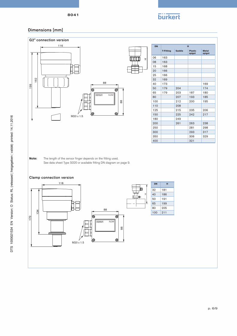
Dimensions [mm]
G2” connection version
116
162
199
88
88
M20 x 1.5
DN H
T-Fitting Saddle Plastic spigot
Metal spigot
06 16308 16315 16820 16625 16632 16940 173 16950 179 204 17465 179 203 187 18080 207 193 185100 212 200 195110 208125 215 235 206150 225 242 217180 249200 261 263 238250 281 298300 293 317350 306 329400 321
Note: The length of the sensor finger depends on the fitting used.
See data sheet Type S020 or available fitting DN diagram on page 9.
Clamp connection version
88
88
M20 x 1.5
116
170
134
H
DN H
32 181
40 186
50 191
65 199
80 205
100 211
8041
p. 7/9
Ordering information and chart for flowmeter Type 8041
• G2” connection to use with S020 Fitting for flowmeter with G2” connection.
A complete flowmeter Type 8041 with G2” connection consists of a flowmeter Type 8041 (with G2” connection) and a Bürkert fitting Type S020
The following information is necessary for the selection of a complete device:
•Item no. of the desired flowmeter Type 8041 (see ordering chart, below)
•Item no. of the selected fitting Type S020 for flowmeter with G2” connection (see separate data sheet)
Vo
lta
ge
su
pp
ly
Ou
tpu
t
Re
lay
Ho
usin
g
ma
teri
al
Se
als
Se
nso
r
ve
rsio
n
Certificates
Ce
rtif
ica
tio
ns
Ele
ctr
ica
l
co
nn
ecti
on
Ite
m n
o.
FD
A
EC
R1935/
2004
1)
18...36 V DC 4...20 mA, frequency
1 PC FKM short, PVDF 2 cable glands 558 064
long, PVDF 2 cable glands 558 065
PPA FKM short, stainless steel) 2 cable glands 552 779
long, stainless steel 2 cable glands 552 780
PPA FKM short, stainless steel 2 cable glands 561 606
long, stainless steel 2 cable glands 561 607
Note: 1 EPDM seal contained in the kit 551775 , 1 relay connection kit 552 812 are supplied with each flowmeter.1) if FKM seal mounted as standard at factory is replaced with the EPDM seal included in the delivery.
• Clamp connection to use with S020 Fitting for flowmeter with clamp connection.
A complete flowmeter Type 8041 with clamp connection consists of a flowmeter Type 8041 (with clamp connection), a Bürkert fitting Type S020, a clamp
collar and a fitting/flowmeter seal
The following information is necessary for the selection of a complete device:
•Item no. of the desired flowmeter Type 8041 (see ordering chart, below)
•Item no. of the selected fitting Type S020 for flowmeter with clamp connection (see separate data sheet)
•Item no. of the selected fitting/flowmeter seal - EPDM or FEP (see ordering chart, p. 8)
•Item no. of the clamp collar (see ordering chart, p. 8)
Vo
lta
ge
su
pp
ly
Ou
tpu
t
Re
lay
Ho
usin
g
ma
teri
al
Fit
tin
g/fl
ow
-
me
ter
se
als
*
Se
nso
r
ve
rsio
n
Certificates
Ele
ctr
ica
l
co
nn
ecti
on
Ite
m n
o.
FD
A
EC
R1935/
2004
1)
18...36 V DC4...20 mA, frequency
1 PCEPDM or FEP
Clamp, stainless steel 2 cable glands 564 688
Note: 1 Kit 565384 and 1 relay connection kit 552 812 are supplied with each flowmeter.* Has to be ordered separately1) Only if mounted with EPDM seal.
8041
p. 8/9
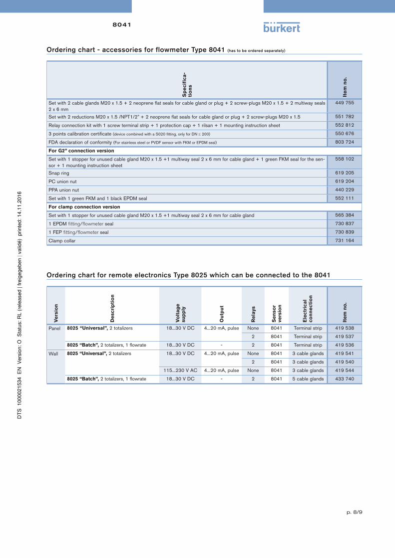
Ordering chart - accessories for flowmeter Type 8041 (has to be ordered separately)
Sp
ecif
ica
-
tio
ns
Ite
m n
o.
Set with 2 cable glands M20 x 1.5 + 2 neoprene flat seals for cable gland or plug + 2 screw-plugs M20 x 1.5 + 2 multiway seals 2 x 6 mm
449 755
Set with 2 reductions M20 x 1.5 /NPT1/2” + 2 neoprene flat seals for cable gland or plug + 2 screw-plugs M20 x 1.5 551 782
Relay connection kit with 1 screw terminal strip + 1 protection cap + 1 rilsan + 1 mounting instruction sheet 552 812
3 points calibration certificate (device combined with a S020 fitting, only for DN 200) 550 676
FDA declaration of conformity (For stainless steel or PVDF sensor with FKM or EPDM seal) 803 724
For G2” connection version
Set with 1 stopper for unused cable gland M20 x 1.5 +1 multiway seal 2 x 6 mm for cable gland + 1 green FKM seal for the sen-sor + 1 mounting instruction sheet
558 102
Snap ring 619 205
PC union nut 619 204
PPA union nut 440 229
Set with 1 green FKM and 1 black EPDM seal 552 111
For clamp connection version
Set with 1 stopper for unused cable gland M20 x 1.5 +1 multiway seal 2 x 6 mm for cable gland 565 384
1 EPDM fitting/flowmeter seal 730 837
1 FEP fitting/flowmeter seal 730 839
Clamp collar 731 164
Ordering chart for remote electronics Type 8025 which can be connected to the 8041
Ve
rsio
n
De
scri
pti
on
Vo
lta
ge
su
pp
ly
Ou
tpu
t
Re
lays
Se
nso
r
ve
rsio
n
Ele
ctr
ica
l
co
nn
ecti
on
Ite
m n
o.
Panel 8025 “Universal”, 2 totalizers 18...30 V DC 4...20 mA, pulse None 8041 Terminal strip 419 538
2 8041 Terminal strip 419 537
8025 “Batch”, 2 totalizers, 1 flowrate 18...30 V DC - 2 8041 Terminal strip 419 536
Wall 8025 “Universal”, 2 totalizers 18...30 V DC 4...20 mA, pulse None 8041 3 cable glands 419 541
2 8041 3 cable glands 419 540
115...230 V AC 4...20 mA, pulse None 8041 3 cable glands 419 544
8025 “Batch”, 2 totalizers, 1 flowrate 18...30 V DC - 2 8041 5 cable glands 433 740
8041
p. 9/9
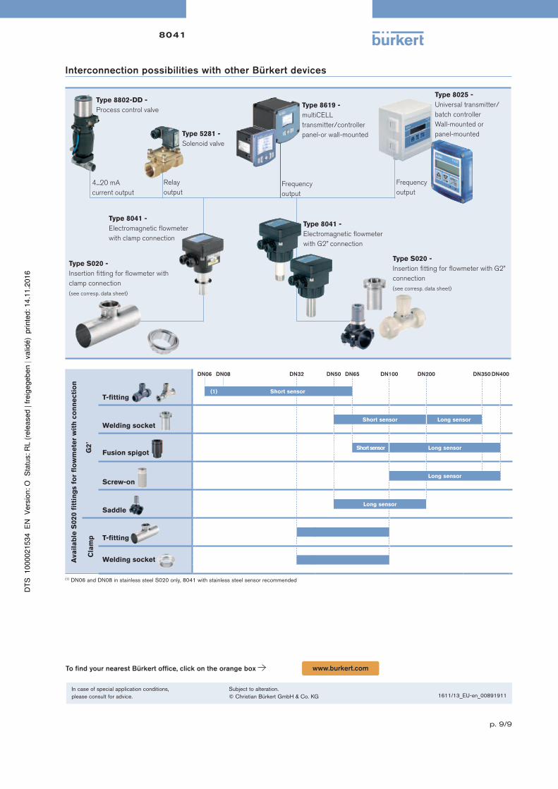
Interconnection possibilities with other Bürkert devices
Type 5281 -
Solenoid valve
Type 8802-DD -
Process control valve
Type 8025 -
Universal transmitter/
batch controller
Wall-mounted or
panel-mounted
4...20 mA
current output
Frequency
output
Type 8041 -
Electromagnetic flowmeter
with G2” connection
Type S020 -
Insertion fitting for flowmeter with G2”
connection
(see corresp. data sheet)
Relay
output
Type 8041 -
Electromagnetic flowmeter
with clamp connection
Type S020 -
Insertion fitting for flowmeter with
clamp connection
(see corresp. data sheet)
Type 8619 -
multiCELL
transmitter/controller
panel-or wall-mounted
Frequency
output
Ava
ila
ble
S020 f
itti
ng
s f
or
flo
wm
ete
r w
ith
co
nn
ecti
on
DN06 DN08 DN32 DN50 DN65 DN100 DN200 DN350 DN400
G2
”
T-fitting (1) Short sensor
Welding socket Short sensor Long sensor
Fusion spigot
Short sensor Long sensor
Screw-on
Long sensor
Saddle
Long sensor
Cla
mp T-fitting
Welding socket
(1) DN06 and DN08 in stainless steel S020 only, 8041 with stainless steel sensor recommended
To find your nearest Bürkert office, click on the orange box www.burkert.com
In case of special application conditions,please consult for advice.
Subject to alteration.© Christian Bürkert GmbH & Co. KG 1611/13_EU-en_00891911