Embed Size (px)
Citation preview
®
SPECIFICATION
DCSUPPLY8V to 35V continuous
CRANKINGDROPOUTSAble to survive 0V for 50mS, providing supplywas at least 10V before dropout and supplyrecovers to 5V. This is achieved without theneed for internal batteries
MAXIMUMOPERATINGCURRENT460mA at 12V. 245mA at 24V
MAXIMUMSTANDBYCURRENT375mA at 12V. 200mA at 24V
ALTERNATOR INPUT RANGE15V(L-N) to 333V AC (L-N) absolute maximum
ALTERNATOR INPUT FREQUENCY50Hz - 60Hz at rated engine speed (Minimum:15V AC L-N)
MAGNETIC PICK-UP VOLTAGERANGE+/- 0.5V to 70V Peak
MAGNETIC INPUT FREQUENCY10,000 Hz (max)
MAINS SENSING RANGE15V(L-N) to 333V AC (L-N) absolute maximum
MAINS SENSING INPUT FREQUENCY50Hz-60Hz (Minimum: 15V AC L-N)
START RELAYOUTPUT16A DC at supply voltage
FUEL RELAYOUTPUT16A DC at supply voltage
AUXILIARY RELAYOUTPUTSThree outputs 5 Amp DC at supply voltageTwo outputs volt free 8 Amp at 250V AC
GENERATOR LOADINGRELAYOUTPUT8A AC 250V
MAINS LOADINGRELAYOUTPUT
8A AC 250V
CHARGE FAIL/EXCITATION RANGE
0V to 35V
BUILT-IN GOVERNORANDAVRCONTROLFully IsolatedMinimum Load Impedance:1000ΩGain Volts: 0V-10V DCOffset Volts: + / - 10V DC
DIMENSIONS240mm x 172mm x 57mm9.4” x 6.8” x 2.2”
PANEL CUTOUT220mm x 160mm8.7” x 6.3”
ENCLOSURE PROTECTIONIP55 (with optional gasket)IP42 (without gasket)
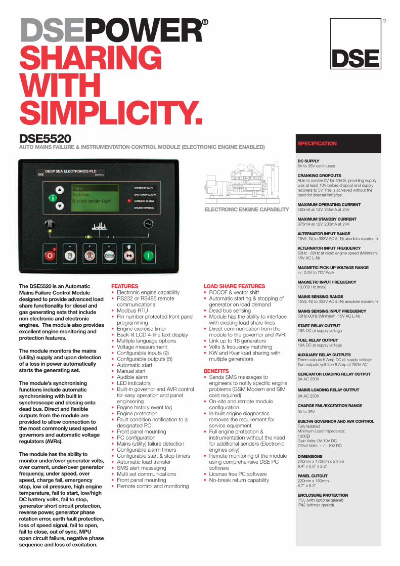
The DSE5520 is an AutomaticMains Failure Control Moduledesigned to provide advanced loadshare functionality for diesel andgas generating sets that includenon electronic and electronicengines. The module also providesexcellent engine monitoring andprotection features.
The module monitors the mains(utility) supply and upon detectionof a loss in power automaticallystarts the generating set.
The module’s synchronisingfunctions include automaticsynchronising with built insynchroscope and closing ontodead bus. Direct and flexibleoutputs from the module areprovided to allow connection tothe most commonly used speedgovernors and automatic voltageregulators (AVRs).
The module has the ability tomonitor under/over generator volts,over current, under/over generatorfrequency, under speed, overspeed, charge fail, emergencystop, low oil pressure, high enginetemperature, fail to start, low/highDC battery volts, fail to stop,generator short circuit protection,reverse power, generator phaserotation error, earth fault protection,loss of speed signal, fail to open,fail to close, out of sync, MPUopen circuit failure, negative phasesequence and loss of excitation.
FEATURES• Electronic engine capability• RS232 or RS485 remotecommunications
• Modbus RTU• Pin number protected front panelprogramming
• Engine exercise timer• Back-lit LCD 4-line text display• Multiple language options• Voltage measurement• Configurable inputs (9)• Configurable outputs (5)• Automatic start• Manual start• Audible alarm• LED indicators• Built-in governor and AVR controlfor easy operation and panelengineering
• Engine history event log• Engine protection• Fault condition notification to adesignated PC
• Front panel mounting• PC configuration• Mains (utility) failure detection• Configurable alarm timers• Configurable start & stop timers• Automatic load transfer• SMS alert messaging• Multi set communications• Front panel mounting• Remote control and monitoring
LOAD SHARE FEATURES• ROCOF & vector shift• Automatic starting & stopping ofgenerator on load demand
• Dead bus sensing• Module has the ability to interfacewith existing load share lines
• Direct communication from themodule to the governor and AVR
• Link up to 16 generators• Volts & frequency matching• KW and Kvar load sharing withmultiple generators
BENEFITS• Sends SMS messages toengineers to notify specific engineproblems (GSM Modem and SIMcard required)
• On-site and remote moduleconfiguration
• In-built engine diagnosticsremoves the requirement forservice equipment
• Full engine protection &instrumentation without the needfor additional senders (Electronicengines only)
• Remote monitoring of the moduleusing comprehensive DSE PCsoftware
• License free PC software• No-break return capability
DSEPOWER®
SHARINGWITHSIMPLICITY.DSE5520AUTOMAINS FAILURE & INSTRUMENTATIONCONTROLMODULE (ELECTRONIC ENGINE ENABLED)
ELECTRONICENGINECAPABILITY

OPERATIONThe module is operated using the front STOP/RESET, MANUAL, AUTO andSTART pushbuttons. Three of these push buttons include an LED indicator.Additional pushbuttons provide LCD display scroll, lamp test, mutefunctionality and breaker control.
BUILT-IN FUNCTIONS• Alternator under/over volts• Alternator under/over frequency• Warning or shutdown on engine temperature, over/under speed, oilpressure
• Warning, shutdown or electrical trip on battery volts or over current• Shutdown or electrical trip on reverse power, phase rotation or shortcircuit fault
• Earth fault shutdown• Adjustable crank cycle/attempts• Full remote control and telemetry• 9 configurable digital inputs• 5 configurable and 2 fixed relay outputs• System lock input• Load switching control push-button inputs• Restricted access to programming via PIN number• Loss of excitation• Negative phase sequence• ROCOF/vector shift (mains (utility) decoupling)• Peak lopping• Peak shaving• Mains (utility) reverse power
INSTRUMENTATION ANDALARMSThe DSE5520 module provides advanced metering and alarm functionalityvia the LCD display. The information can be accessed using the display scrollpushbuttons. The table below shows the instrumentation and alarm featuresthe module provides.
Engine SpeedEngine Oil PressureCoolant TemperatureBattery VoltageCharge Alt VoltsEngine Run TimeNumber of StartsAdditional instrumentation as provided by the electronic ECUNext Maintenance (if enabled)Fuel LevelGenerator Volts (L-N)Generator Volts (L-L) Gen HzGenerator AmpsGenerator Earth CurrentGenerator kW (L1,L2,L3)Generator Total kWGenerator pf (L1,L2,L3)Generator Average pfGenerator Total kVArGenerator kWhGenerator kVAhGenerator kVArhGenerator Phase SequenceSynchroscopeMains (utility) Volts (L- N)Mains (utility)Volts (L-L)Mains (utility)HzMains (utility)AmpsMains (utility)kWMains (utility)kVAMains (utility)pfMains (utility)kVArMains (utility)Phase SequenceGenerator kVA
TELEMETRYThe module gives the user fulltelemetry facilities when using theoptional communications software.The module can be connected to aPC using the DSE810 PC interfaceor by using a suitable modem.
The PC software is MicrosoftWindows™ based. All access intothe module can be configured tobecome password protected toprevent unauthorised entry. ThePC software allows the module tobe controlled from a remote location.
COMMUNICATIONSThe DSE5520 has a number ofdifferent communicationcapabilities.
SMSMessagingWhen the module detects an alarmcondition, it has the ability to sendan SMS message to a dedicatedmobile number, notifying an engineerof the problem. (GSM Modem andSIM Card required).
Remote CommunicationsWhen the module detects an alarmcondition, it dials out to a PCnotifying the user of the exact alarmcondition (modem required).
BuildingManagementThe module has been designed tobe integrated into new and existingbuilding management systems.
PC SoftwareThe module has the ability to becontrolled, configured and monitoredfrom a remote PC, using theDSE810 interface.
EVENT LOGThe module includes acomprehensive event log thatshows the 25 most recent alarmconditions and the date and timethat they occurred. This functionassists the user when fault findingand maintaining a generating set.
EXPANSIONMODULESDSE157 Relay InputExpansion ModuleDSE545 & DSE548 RemoteAnnunciation Expansion ModuleDSE130 Input Expansion Module
TYPICAL LOAD SHAREAPPLICATION
LOAD
G
ELECTROMAGNETIC CAPABILITYBS EN 61000-6-2EMC Generic Emission Standard for theIndustrial EnvironmentBS EN 61000-6-4EMC Generic Emission Standard for theIndustrial Environment
ELECTRICAL SAFETYBS EN 60950Safety of Information Technology Equipment,including Electrical Business Equipment
TEMPERATUREBS EN 60068-2-2Test Ab to +70oC 60067-2-2 HotTest Ab to -30oC 60068-2-1 Cold
VIBRATIONBS EN 60068-2-6Ten sweeps in each of three major axes5Hz to 8Hz @ +/-7.5mm, 8Hz to 500Hz @ 2gn
HUMIDITYBS 2011 part 2.1 60068-2-30Test Cb Ob Cyclic93% RH @ 40oC for 48 hours
SHOCKBS EN 60068-2-27Three shocks in each of three major axes15gn in 11mS
ENVIRONMENTAL TESTINGSTANDARDS
®
DSE5520
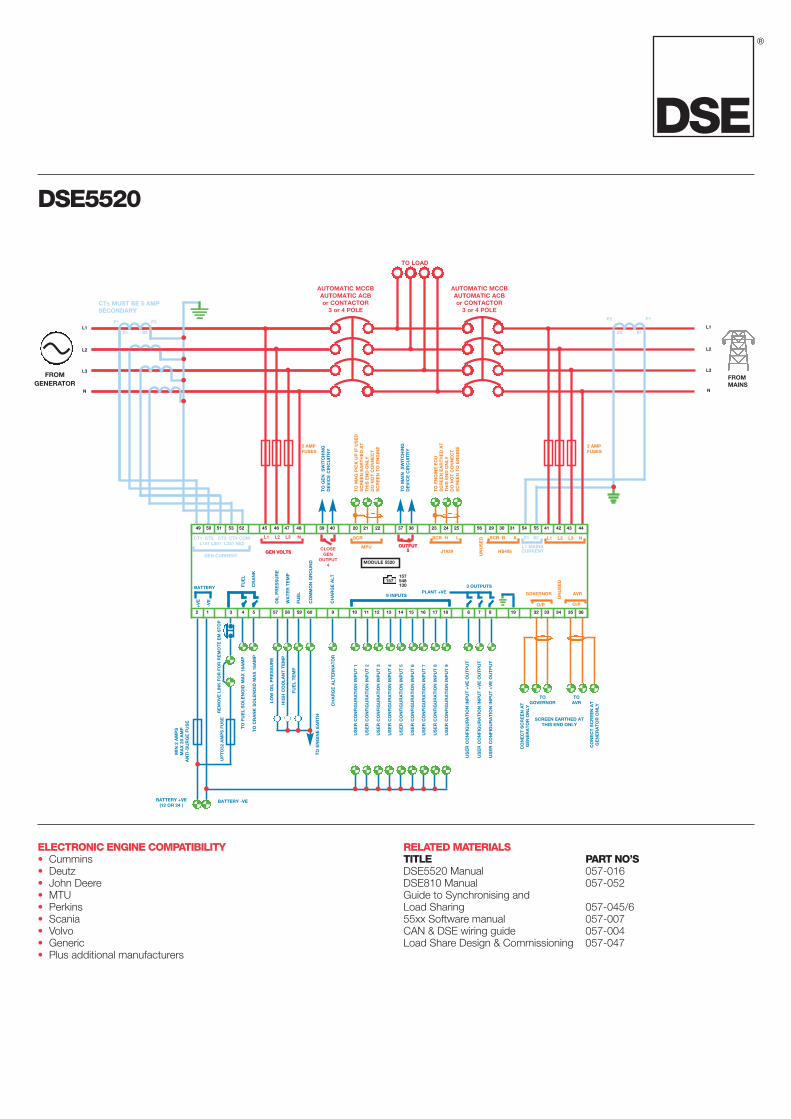
ELECTRONIC ENGINE COMPATIBILITY• Cummins• Deutz• John Deere• MTU• Perkins• Scania• Volvo• Generic• Plus additional manufacturers
RELATEDMATERIALSTITLE PART NO’SDSE5520 Manual 057-016DSE810 Manual 057-052Guide to Synchronising andLoad Sharing 057-045/655xx Software manual 057-007CAN & DSE wiring guide 057-004Load Share Design & Commissioning 057-047
CTs MUST BE 5 AMPSECONDARY
FROMMAINS
TO
MA
GP
ICK
UP
IFU
SE
DS
CR
EE
NE
AR
TH
ED
AT
TH
ISE
ND
ON
LYD
ON
OT
CO
NN
EC
TS
CR
EE
NT
OE
NG
INE
TO
GE
NS
WIT
CH
ING
DE
VIC
EC
IRC
UIT
RY
TO
MA
INS
WIT
CH
ING
DE
VIC
EC
IRC
UIT
RY
2 AMPFUSES
2 AMPFUSES
TO
EN
GIN
EE
CU
SC
RE
EN
EA
RT
HE
DA
TT
HIS
EN
DO
NLY
DO
NO
TC
ON
NE
CT
SC
RE
EN
TO
EN
GIN
E
AUTOMATIC MCCBAUTOMATIC ACBor CONTACTOR
3 or 4 POLE
AUTOMATIC MCCBAUTOMATIC ACBor CONTACTOR
3 or 4 POLE
TO LOAD
P1
S1 S2
P2P1
S1S2
P2
CT1 CT2 CT3 CT4 COML151 L251 L351 N52
L1 L2 L3 N L1 L2 L3 NS1 S2
GEN VOLTSGEN VOLTS
49 50 51 53 52 45 46 47 48 39 40 20 21 22 37 38 23 24 25 56 29 30 31 54 55 41 42 43 44
2 1 3 4 5 57 58 59 60 9 10 11 12 13 14 15 16 17 18 6 7 8 19 32 33 34 35 36
SCR
MPU OUTPUT5
OUTPUT5
UN
US
ED
L1 MAINSCURRENT
SCR H L
J1939
SCR B A
HS485CLOSEGEN
OUTPUT4
BATTERY
+V
E
-VE
FUE
L
RE
MO
VE
LIN
KFO
RFO
RR
EM
OT
EE
MS
TO
P
MIN
2A
MP
SM
AX
20A
MP
AN
TI-
SU
RG
EFU
SE
UP
TO
32A
MP
SFU
SE
BATTERY +VE(12 OR 24 )
BATTERY -VE
TO
FUE
LS
OLE
NO
IDM
AX
16A
MP
TO
CR
AN
KS
OLE
NO
IDM
AX
16A
MP
LOW
OIL
PR
ES
SU
RE
HIG
HC
OO
LAN
TT
EM
P
FUE
LT
EM
P
CH
AR
GE
ALT
ER
NA
TO
R
TO
EN
GIN
EE
AR
TH
US
ER
CO
NFI
GU
RA
TIO
NIN
PU
T1
US
ER
CO
NFI
GU
RA
TIO
NIN
PU
T2
US
ER
CO
NFI
GU
RA
TIO
NIN
PU
T3
US
ER
CO
NFI
GU
RA
TIO
NIN
PU
T4
US
ER
CO
NFI
GU
RA
TIO
NIN
PU
T5
US
ER
CO
NFI
GU
RA
TIO
NIN
PU
T6
US
ER
CO
NFI
GU
RA
TIO
NIN
PU
T7
US
ER
CO
NFI
GU
RA
TIO
NIN
PU
T8
US
ER
CO
NFI
GU
RA
TIO
NIN
PU
T9
US
ER
CO
NFI
GU
RA
TIO
NIN
PU
T+
VE
OU
TP
UT
US
ER
CO
NFI
GU
RA
TIO
NIN
PU
T+
VE
OU
TP
UT
US
ER
CO
NFI
GU
RA
TIO
NIN
PU
T+
VE
OU
TP
UT
CO
NE
CT
SC
RE
EN
AT
GE
NE
RA
TO
RO
NLY
SCREEN EARTHED ATTHIS END ONLY
TOGOVERNOR
TOAVR
CO
NE
CT
SC
RE
EN
AT
GE
NE
RA
TO
RO
NLY
CR
AN
K
OIL
PR
ES
SU
RE
WA
TE
RT
EM
P
FUE
L
CO
MM
ON
GR
OU
ND
CH
AR
GE
ALT
9 INPUTSPLANT +VE
3 OUTPUTS
GOVERNOR AVR
O/P O/P
UN
US
ED157
157548130
MODULE 5520
L1
L3
N
L2
L1
L3
N
L2
GEN CURRENT
FROMGENERATOR

®
DEEP SEA ELECTRONICS INC3230 Williams AvenueRockfordIL 61101-2668 USA
TELEPHONE+1 (815) 316 8706
FACSIMILE+1 (815) 316 8708
WEBSITEwww.deepseausa.com
DEEP SEA ELECTRONICS PLCHighfield HouseHunmanby Industrial EstateHunmanby, North YorkshireYO14 0PH England
TELEPHONE+44 (0)1723 890099
FACSIMILE+44 (0)1723 893303
WEBSITEwww.deepseaplc.com
Registered in England & Wales No.01319649 VAT No.316923457
YOUR LOCAL DISTRIBUTOR.
DEEP SEA ELECTRONICS PLCmaintains a policy of continuous development and reserves the right tochange the details shown on this data sheet without prior notice. The contents are intended for guidance only.
055-040/02/08 (2)
This data sheet is printed on 9lives 55 Silk, which is produced with 55% recycled fibrefrom both pre and post-consumer sources, together with 45% virgin ECF fibre.
PENDING