Embed Size (px)
Citation preview
Reference
D-Series Harris J/S (JSC-2) Jog-Shuttle Panel Reference
11-April-2011
D-Series Harris J/S (JSC-2) Jog-Shuttle Panel
Reference
Publication Information © 2014 Imagine Communications Corp. Proprietary and Confidential. Imagine Communications considers this document and its contents to be proprietary and confidential. Except for making a reasonable number of copies for your own internal use, you may not reproduce this publication, or any part thereof, in any form, by any method, for any purpose, or in any language other than English without the written consent of Imagine Communications. All others uses are illegal. This publication is designed to assist in the use of the product as it exists on the date of publication of this manual, and may not reflect the product at the current time or an unknown time in the future. This publication does not in any way warrant description accuracy or guarantee the use for the product to which it refers. Imagine Communications reserves the right, without notice to make such changes in equipment, design, specifications, components, or documentation as progress may warrant to improve the performance of the product.
Trademarks Product names and other brands (such as ADC™, D-Series™, Nexio®, Nexio® Insight, Nexio® Motion, PowerSmart®, Versio™) are trademarks or trade names of Imagine Communications or its subsidiaries. Microsoft® and Windows® are registered trademarks of Microsoft Corporation. All other trademarks and trade names are the property of their respective companies.
Contact Information Imagine Communications has office locations around the world. For domestic and international location and contact information see: http://www.imaginecommunications.com/contact-us/
Support Contact Information For domestic and international support contact information see: Support Contacts: http://www.imaginecommunications.com/services/technical-support/
eCustomer Portal: http://support.imaginecommunications.com
© 2014 Imagine Communications Corp. Proprietary and Confidential 9-April-2014 | Page 2 of 21
D-Series Harris J/S (JSC-2) Jog-Shuttle Panel
Reference Contents
Contents About this Manual ............................................................................. 5
Audience ..................................................................................................................................... 5 Measurement Standards ............................................................................................................. 5 Product Unpacking Notes ........................................................................................................... 5 WEEE and RoHS Compliance .................................................................................................... 5
Harris J/S (JSC-2) Ingest Control Panel ............................................ 7 About the Harris J/S Control Panel ............................................................................................. 7
Panel Features ........................................................................................................................ 7 Specifications .............................................................................................................................. 8
Operation .......................................................................................... 9 Panel Layout ............................................................................................................................... 9 Timecode Display ...................................................................................................................... 10 Jog/Shuttle Wheel ..................................................................................................................... 10
Direction Indicator ................................................................................................................. 10 Button Mapping ......................................................................................................................... 11
DALstation Functionality ....................................................................................................... 11 DALingest Functionality ........................................................................................................ 14
Troubleshooting ......................................................................................................................... 17 Loss of JSC-2 Comms .......................................................................................................... 17
Configuration ................................................................................... 18 DALstation Configuration .......................................................................................................... 18 DALingest Configuration ........................................................................................................... 18 Cabling Pinouts ......................................................................................................................... 18
Unit Replacement ............................................................................ 20 Notice to the Original Purchaser ................................................. Error! Bookmark not defined. To Return a Unit .......................................................................... Error! Bookmark not defined. To Order a New or Replacement Unit ....................................................................................... 20
© 2014 Imagine Communications Corp. Proprietary and Confidential 9-April-2014 | Page 3 of 21

Dseries Harris J/S (JSC-2) Jog-Shuttle Control Panel
Reference About this Manual
About this Manual
Audience This manual is intended as a general reference and for use by engineers or technicians when installing professional automation computers.
Measurement Standards The following measurement standards are used in this manual:
Rack Unit (RU) is an Imperial standard measurement for device height. (While also seen as U.) [1RU = 44.45mm = 1.75 inches]
19” Rack Standard is an international standard for racking width. [19” Rackmount standard = 482.6mm]
Other measures for in-document conversion: (1m = 3.281ft), (0.3048m = 1ft), (25.4mm = 1in), (1kg = 2.205lb)
Website for length & weight conversions: http://www.convert-me.com/en/convert
Product Unpacking Notes Thoroughly inspect all articles immediately upon receipt. Any damage discovered should be cause for a damage claim against the carrier.
WEEE and RoHS Compliance Panels addressed in this document are WEEE and RoHS Compliant. This includes compliance with Electrical and Electronic Equipment (WEEE) and Restriction on Hazardous Substances (RoHS) (Combined WEEE/RoHS) requirements now mandated in Europe, and being adopted in other parts of the world.
Restriction of Hazardous Substances Directive (RoHS) 2002/95/EC mandates: Recycling of devices at end of life and the elimination or reduction of a list of hazardous substances. This includes six key hazardous materials typically used in the manufacture of various types of electronic and electrical equipment: Lead, Mercury, Cadmium, Hexavalent chromium (chromium VI or Cr6+), Polybrominated biphenyls (PBB), and Polybrominated diphenyl ether (PBDE)
© 2014 Imagine Communications Corp. Proprietary and Confidential 9-April-2014 | Page 5 of 21
Dseries Harris J/S (JSC-2) Jog-Shuttle Control Panel
Reference About this Manual
Waste Electrical and Electronic Equipment Directive (WEEE Directive) 2002/96/EC sets collection, recycling and recovery targets for all types of electrical goods. The directive imposes the responsibility for the disposal of waste electrical and electronic equipment (WEEE) on the manufacturers of such equipment. The companies are compelled to use the collected waste in an ecological-friendly manner, either by ecological disposal or by reuse/refurbishment of the collected WEEE. Under WEEE "Users of electrical and electronic equipment from private households should have the possibility of returning WEEE at least free of charge"
© 2014 Imagine Communications Corp. Proprietary and Confidential 9-April-2014 | Page 6 of 21

Dseries Harris J/S (JSC-2) Jog-Shuttle Control Panel
Reference J/S (JSC-2) Ingest Control Panel
J/S (JSC-2) Ingest Control Panel
About the J/S Control Panel The Harris J/S Control panel (JSC-2 panel) provides basic transport and jog/shuttle controls in a compact desktop unit. This panel gives operators a choice in controlling ingest environments by providing desktop device transport button control in addition to an automation’s Device Control Interface and a broadcast device’s conventional transport controls.
When used in conjunction with an automation playout or ingest workstation, the workstation displays the events to be controlled and the JSC-2 provides a “hands-on” user interface.
IMPORTANT: The JSC-2 panel is supported by DALstation v3.59.00 or higher, and DALingest v3.30.00 or higher.
Panel Features JSC-2 Panel features include:
Sony Jog – Shuttle knob © 2014 Imagine Communications Corp. Proprietary and Confidential 9-April-2014 | Page 7 of 21
Dseries Harris J/S (JSC-2) Jog-Shuttle Control Panel
Reference J/S (JSC-2) Ingest Control Panel
The jog/shuttle mechanism is a weighted jog wheel and a concentric shuttle ring.
20 control buttons
5 dedicated transport controls
A back-lit LCD time code display for easy and accurate editing.
V2.14 Firmware
The JSC-2 Ingest Panel uses firmware v2.14 to support jog/shuttle status query commands.
Note: Firmware versions prior to v2.14 do not support jog/shuttle querying and the LCD display will appear to become unresponsive if left idle or in the ‘shuttle’ position for a period of time. Moving the shuttle wheel or pressing any button on the control panel will reupdate the display.
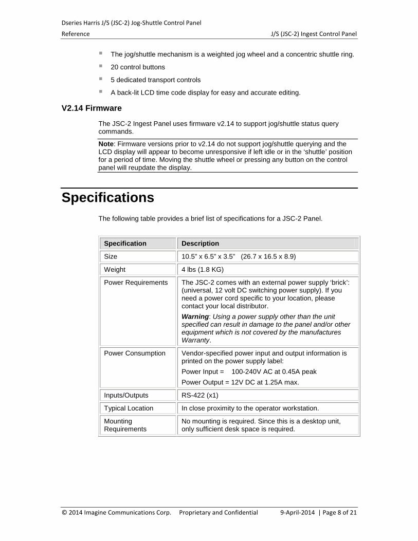
Specifications The following table provides a brief list of specifications for a JSC-2 Panel.
Specification Description
Size 10.5” x 6.5” x 3.5” (26.7 x 16.5 x 8.9)
Weight 4 lbs (1.8 KG)
Power Requirements The JSC-2 comes with an external power supply ‘brick’: (universal, 12 volt DC switching power supply). If you need a power cord specific to your location, please contact your local distributor. Warning: Using a power supply other than the unit specified can result in damage to the panel and/or other equipment which is not covered by the manufactures Warranty.
Power Consumption Vendor-specified power input and output information is printed on the power supply label: Power Input = 100-240V AC at 0.45A peak Power Output = 12V DC at 1.25A max.
Inputs/Outputs RS-422 (x1)
Typical Location In close proximity to the operator workstation.
Mounting Requirements
No mounting is required. Since this is a desktop unit, only sufficient desk space is required.
© 2014 Imagine Communications Corp. Proprietary and Confidential 9-April-2014 | Page 8 of 21
Dseries Harris J/S (JSC-2) Jog-Shuttle Control Panel
Reference Operation
Operation
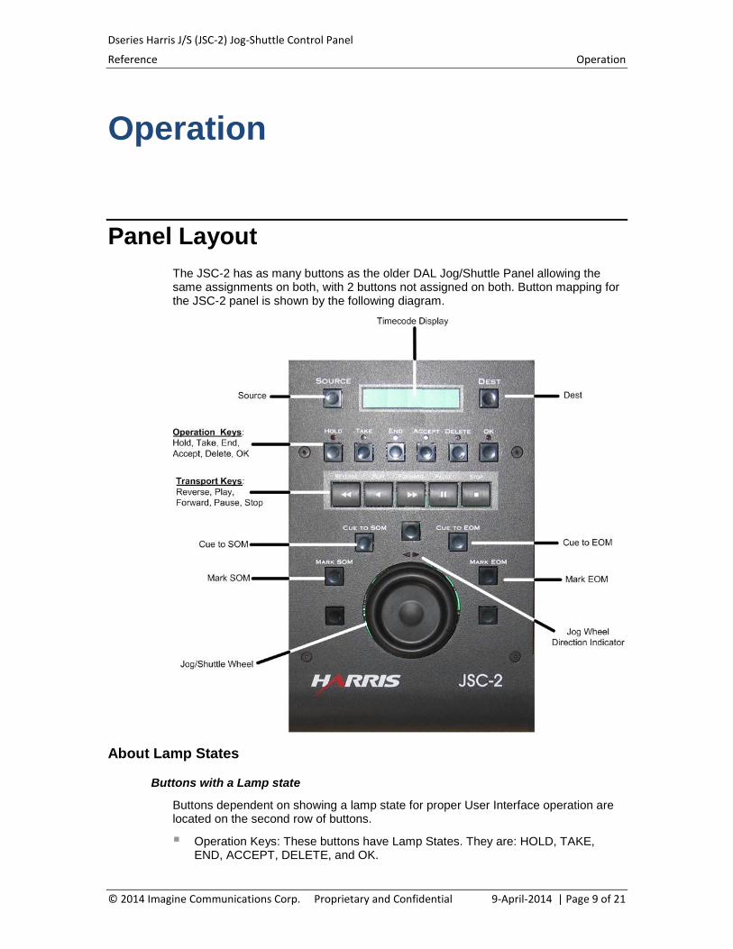
Panel Layout The JSC-2 has as many buttons as the older DAL Jog/Shuttle Panel allowing the same assignments on both, with 2 buttons not assigned on both. Button mapping for the JSC-2 panel is shown by the following diagram.
About Lamp States
Buttons with a Lamp state
Buttons dependent on showing a lamp state for proper User Interface operation are located on the second row of buttons.
Operation Keys: These buttons have Lamp States. They are: HOLD, TAKE, END, ACCEPT, DELETE, and OK.
© 2014 Imagine Communications Corp. Proprietary and Confidential 9-April-2014 | Page 9 of 21
Dseries Harris J/S (JSC-2) Jog-Shuttle Control Panel
Reference Operation
Buttons without a Lamp State
The following buttons do not have Lamp States:
Machine Control buttons: Do not have Lamp States, so do not show transport status.
Source and Dest buttons: Do not have Lamp States. Their states are indicated in the LCD display. The left and rightmost character of the LCD display show an ‘*’ character to
indicate the current mode selection. The ‘*’ character is displayed in the LCD position nearest to the button
associated with the current selection (leftmost for Source selected, rightmost for Destination).
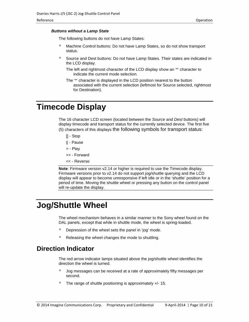
Timecode Display The 16 character LCD screen (located between the Source and Dest buttons) will display timecode and transport status for the currently selected device. The first five (5) characters of this displays the following symbols for transport status:
[] - Stop || - Pause > - Play >> - Forward << - Reverse
Note: Firmware version v2.14 or higher is required to use the Timecode display. Firmware versions prior to v2.14 do not support jog/shuttle querying and the LCD display will appear to become unresponsive if left idle or in the ‘shuttle’ position for a period of time. Moving the shuttle wheel or pressing any button on the control panel will re-update the display.
Jog/Shuttle Wheel The wheel mechanism behaves in a similar manner to the Sony wheel found on the DAL panels, except that while in shuttle mode, the wheel is spring-loaded.
Depression of the wheel sets the panel in ‘jog’ mode.
Releasing the wheel changes the mode to shuttling.
Direction Indicator The red arrow indicator lamps situated above the jog/shuttle wheel identifies the direction the wheel is turned.
Jog messages can be received at a rate of approximately fifty messages per second.
The range of shuttle positioning is approximately +/- 15.
© 2014 Imagine Communications Corp. Proprietary and Confidential 9-April-2014 | Page 10 of 21
Dseries Harris J/S (JSC-2) Jog-Shuttle Control Panel
Reference Operation
The Jog sensitivity of the JSC-2 panel is approximately 3 frames per full revolution- to be in line with other D-Series panels.
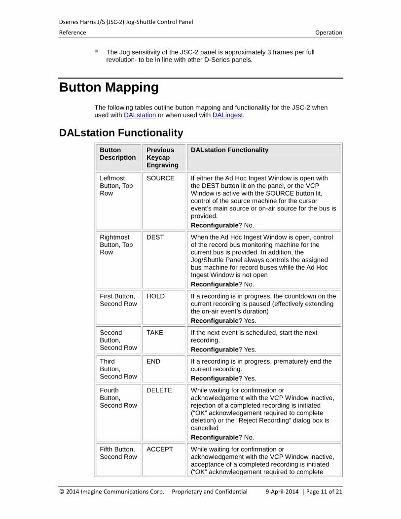
Button Mapping The following tables outline button mapping and functionality for the JSC-2 when used with DALstation or when used with DALingest.
DALstation Functionality Button Description
Previous Keycap Engraving
DALstation Functionality
Leftmost Button, Top Row
SOURCE If either the Ad Hoc Ingest Window is open with the DEST button lit on the panel, or the VCP Window is active with the SOURCE button lit, control of the source machine for the cursor event’s main source or on-air source for the bus is provided. Reconfigurable? No.
Rightmost Button, Top Row
DEST When the Ad Hoc Ingest Window is open, control of the record bus monitoring machine for the current bus is provided. In addition, the Jog/Shuttle Panel always controls the assigned bus machine for record buses while the Ad Hoc Ingest Window is not open Reconfigurable? No.
First Button, Second Row
HOLD If a recording is in progress, the countdown on the current recording is paused (effectively extending the on-air event’s duration) Reconfigurable? Yes.
Second Button, Second Row
TAKE If the next event is scheduled, start the next recording. Reconfigurable? Yes.
Third Button, Second Row
END If a recording is in progress, prematurely end the current recording. Reconfigurable? Yes.
Fourth Button, Second Row
DELETE While waiting for confirmation or acknowledgement with the VCP Window inactive, rejection of a completed recording is initiated (“OK” acknowledgement required to complete deletion) or the “Reject Recording” dialog box is cancelled Reconfigurable? No.
Fifth Button, Second Row
ACCEPT While waiting for confirmation or acknowledgement with the VCP Window inactive, acceptance of a completed recording is initiated (“OK” acknowledgement required to complete
© 2014 Imagine Communications Corp. Proprietary and Confidential 9-April-2014 | Page 11 of 21
Dseries Harris J/S (JSC-2) Jog-Shuttle Control Panel
Reference Operation
Button Description
Previous Keycap Engraving
DALstation Functionality
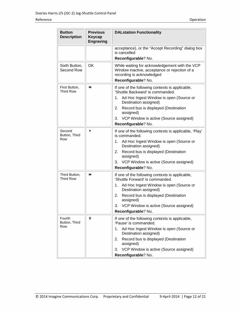
acceptance), or the “Accept Recording” dialog box is cancelled Reconfigurable? No.
Sixth Button, Second Row
OK While waiting for acknowledgement with the VCP Window inactive, acceptance or rejection of a recording is acknowledged Reconfigurable? No.
First Button, Third Row
If one of the following contexts is applicable, ‘Shuttle Backward’ is commanded. 1. Ad Hoc Ingest Window is open (Source or
Destination assigned) 2. Record bus is displayed (Destination
assigned) 3. VCP Window is active (Source assigned) Reconfigurable? No.
Second Button, Third Row
If one of the following contexts is applicable, ‘Play’ is commanded. 1. Ad Hoc Ingest Window is open (Source or
Destination assigned) 2. Record bus is displayed (Destination
assigned) 3. VCP Window is active (Source assigned) Reconfigurable? No.
Third Button, Third Row
If one of the following contexts is applicable, ‘Shuttle Forward’ is commanded. 1. Ad Hoc Ingest Window is open (Source or
Destination assigned) 2. Record bus is displayed (Destination
assigned) 3. VCP Window is active (Source assigned) Reconfigurable? No.
Fourth Button, Third Row
If one of the following contexts is applicable, ‘Pause’ is commanded. 1. Ad Hoc Ingest Window is open (Source or
Destination assigned) 2. Record bus is displayed (Destination
assigned) 3. VCP Window is active (Source assigned) Reconfigurable? No.
© 2014 Imagine Communications Corp. Proprietary and Confidential 9-April-2014 | Page 12 of 21
Dseries Harris J/S (JSC-2) Jog-Shuttle Control Panel
Reference Operation
Button Description
Previous Keycap Engraving
DALstation Functionality
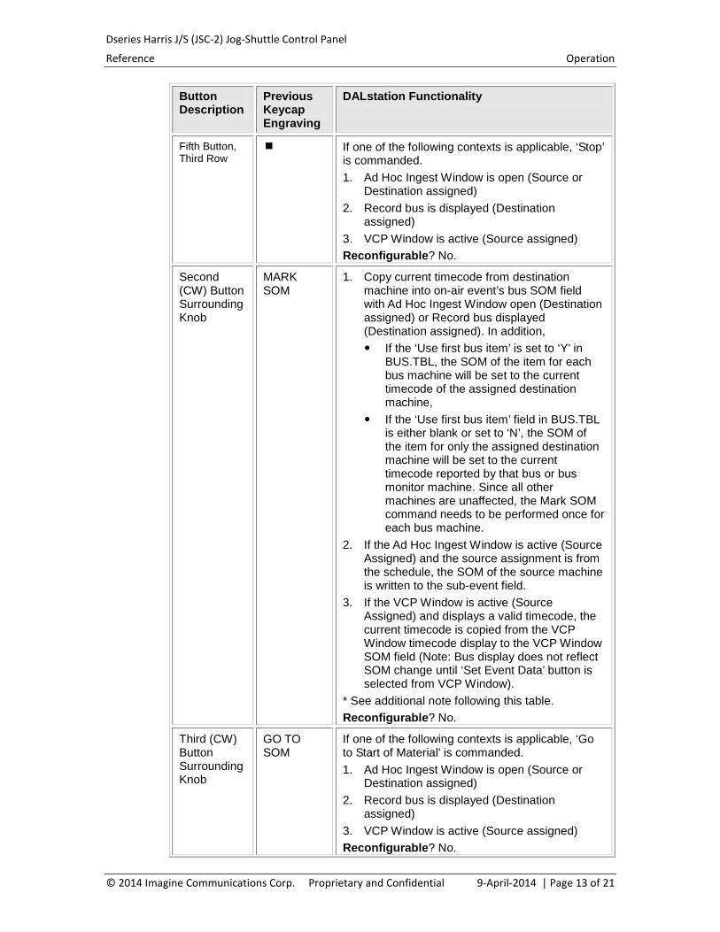
Fifth Button, Third Row
If one of the following contexts is applicable, ‘Stop’ is commanded. 1. Ad Hoc Ingest Window is open (Source or
Destination assigned) 2. Record bus is displayed (Destination
assigned) 3. VCP Window is active (Source assigned) Reconfigurable? No.
Second (CW) Button Surrounding Knob
MARK SOM
1. Copy current timecode from destination machine into on-air event’s bus SOM field with Ad Hoc Ingest Window open (Destination assigned) or Record bus displayed (Destination assigned). In addition, If the ‘Use first bus item’ is set to ‘Y’ in
BUS.TBL, the SOM of the item for each bus machine will be set to the current timecode of the assigned destination machine,
If the ‘Use first bus item’ field in BUS.TBL is either blank or set to ‘N’, the SOM of the item for only the assigned destination machine will be set to the current timecode reported by that bus or bus monitor machine. Since all other machines are unaffected, the Mark SOM command needs to be performed once for each bus machine.
2. If the Ad Hoc Ingest Window is active (Source Assigned) and the source assignment is from the schedule, the SOM of the source machine is written to the sub-event field.
3. If the VCP Window is active (Source Assigned) and displays a valid timecode, the current timecode is copied from the VCP Window timecode display to the VCP Window SOM field (Note: Bus display does not reflect SOM change until ‘Set Event Data’ button is selected from VCP Window).
* See additional note following this table. Reconfigurable? No.
Third (CW) Button Surrounding Knob
GO TO SOM
If one of the following contexts is applicable, ‘Go to Start of Material’ is commanded. 1. Ad Hoc Ingest Window is open (Source or
Destination assigned) 2. Record bus is displayed (Destination
assigned) 3. VCP Window is active (Source assigned) Reconfigurable? No.
© 2014 Imagine Communications Corp. Proprietary and Confidential 9-April-2014 | Page 13 of 21
Dseries Harris J/S (JSC-2) Jog-Shuttle Control Panel
Reference Operation
Button Description
Previous Keycap Engraving
DALstation Functionality
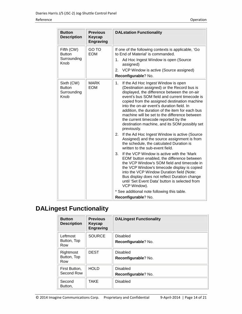
Fifth (CW) Button Surrounding Knob
GO TO EOM
If one of the following contexts is applicable, ‘Go to End of Material’ is commanded. 1. Ad Hoc Ingest Window is open (Source
assigned) 2. VCP Window is active (Source assigned) Reconfigurable? No.
Sixth (CW) Button Surrounding Knob
MARK EOM
1. If the Ad Hoc Ingest Window is open (Destination assigned) or the Record bus is displayed, the difference between the on-air event’s bus SOM field and current timecode is copied from the assigned destination machine into the on-air event’s duration field. In addition, the duration of the item for each bus machine will be set to the difference between the current timecode reported by the destination machine, and its SOM possibly set previously.
2. If the Ad Hoc Ingest Window is active (Source Assigned) and the source assignment is from the schedule, the calculated Duration is written to the sub-event field.
3. If the VCP Window is active with the ‘Mark EOM’ button enabled, the difference between the VCP Window’s SOM field and timecode in the VCP Window’s timecode display is copied into the VCP Window Duration field (Note: Bus display does not reflect Duration change until ‘Set Event Data’ button is selected from VCP Window).
* See additional note following this table. Reconfigurable? No.
DALingest Functionality Button Description
Previous Keycap Engraving
DALingest Functionality
Leftmost Button, Top Row
SOURCE Disabled Reconfigurable? No.
Rightmost Button, Top Row
DEST Disabled Reconfigurable? No.
First Button, Second Row
HOLD Disabled Reconfigurable? No.
Second Button,
TAKE Disabled
© 2014 Imagine Communications Corp. Proprietary and Confidential 9-April-2014 | Page 14 of 21
Dseries Harris J/S (JSC-2) Jog-Shuttle Control Panel
Reference Operation
Button Description
Previous Keycap Engraving
DALingest Functionality
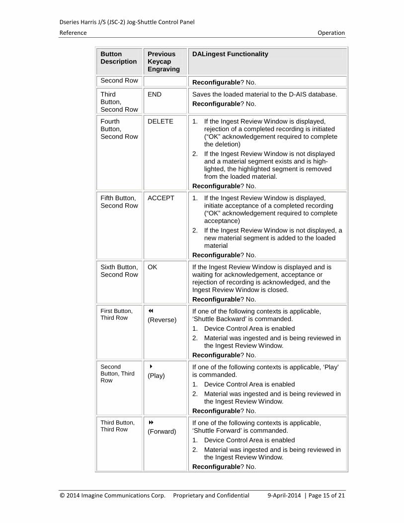
Second Row Reconfigurable? No.
Third Button, Second Row
END Saves the loaded material to the D-AIS database. Reconfigurable? No.
Fourth Button, Second Row
DELETE 1. If the Ingest Review Window is displayed, rejection of a completed recording is initiated (“OK” acknowledgement required to complete the deletion)
2. If the Ingest Review Window is not displayed and a material segment exists and is high-lighted, the highlighted segment is removed from the loaded material.
Reconfigurable? No.
Fifth Button, Second Row
ACCEPT 1. If the Ingest Review Window is displayed, initiate acceptance of a completed recording (“OK” acknowledgement required to complete acceptance)
2. If the Ingest Review Window is not displayed, a new material segment is added to the loaded material
Reconfigurable? No.
Sixth Button, Second Row
OK If the Ingest Review Window is displayed and is waiting for acknowledgement, acceptance or rejection of recording is acknowledged, and the Ingest Review Window is closed. Reconfigurable? No.
First Button, Third Row
(Reverse) If one of the following contexts is applicable, ‘Shuttle Backward’ is commanded. 1. Device Control Area is enabled 2. Material was ingested and is being reviewed in
the Ingest Review Window. Reconfigurable? No.
Second Button, Third Row
(Play) If one of the following contexts is applicable, ‘Play’ is commanded. 1. Device Control Area is enabled 2. Material was ingested and is being reviewed in
the Ingest Review Window. Reconfigurable? No.
Third Button, Third Row
(Forward) If one of the following contexts is applicable, ‘Shuttle Forward’ is commanded. 1. Device Control Area is enabled 2. Material was ingested and is being reviewed in
the Ingest Review Window. Reconfigurable? No.
© 2014 Imagine Communications Corp. Proprietary and Confidential 9-April-2014 | Page 15 of 21
Dseries Harris J/S (JSC-2) Jog-Shuttle Control Panel
Reference Operation
Button Description
Previous Keycap Engraving
DALingest Functionality
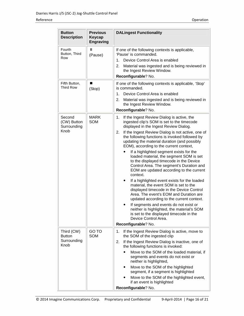
Fourth Button, Third Row
(Pause) If one of the following contexts is applicable, ‘Pause’ is commanded. 1. Device Control Area is enabled 2. Material was ingested and is being reviewed in
the Ingest Review Window. Reconfigurable? No.
Fifth Button, Third Row
(Stop) If one of the following contexts is applicable, ‘Stop’ is commanded. 1. Device Control Area is enabled 2. Material was ingested and is being reviewed in
the Ingest Review Window. Reconfigurable? No.
Second (CW) Button Surrounding Knob
MARK SOM
1. If the Ingest Review Dialog is active, the ingested clip’s SOM is set to the timecode displayed in the Ingest Review Dialog.
2. If the Ingest Review Dialog is not active, one of the following functions is invoked followed by updating the material duration (and possibly EOM), according to the current context, If a highlighted segment exists for the
loaded material, the segment SOM is set to the displayed timecode in the Device Control Area. The segment’s Duration and EOM are updated according to the current context.
If a highlighted event exists for the loaded material, the event SOM is set to the displayed timecode in the Device Control Area. The event’s EOM and Duration are updated according to the current context.
If segments and events do not exist or neither is highlighted, the material’s SOM is set to the displayed timecode in the Device Control Area.
Reconfigurable? No.
Third (CW) Button Surrounding Knob
GO TO SOM
1. If the Ingest Review Dialog is active, move to the SOM of the ingested clip
2. If the Ingest Review Dialog is inactive, one of the following functions is invoked: Move to the SOM of the loaded material, if
segments and events do not exist or neither is highlighted,
Move to the SOM of the highlighted segment, if a segment is highlighted
Move to the SOM of the highlighted event, if an event is highlighted
Reconfigurable? No. © 2014 Imagine Communications Corp. Proprietary and Confidential 9-April-2014 | Page 16 of 21
Dseries Harris J/S (JSC-2) Jog-Shuttle Control Panel
Reference Operation
Button Description
Previous Keycap Engraving
DALingest Functionality
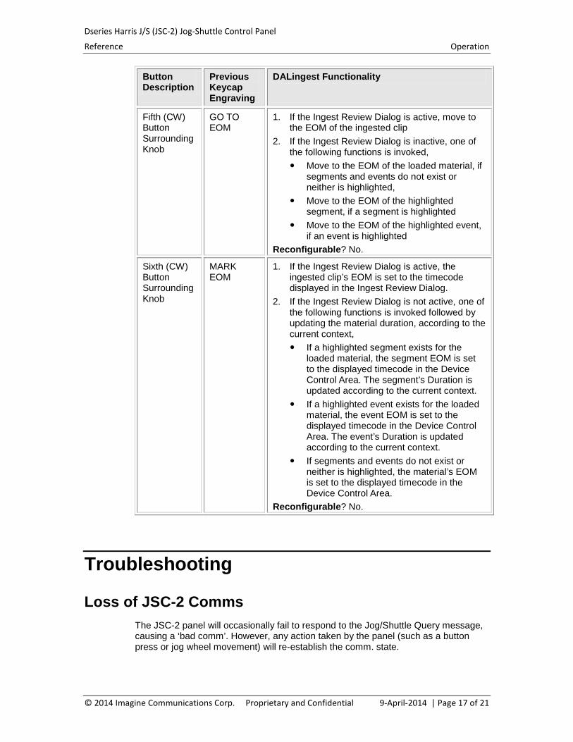
Fifth (CW) Button Surrounding Knob
GO TO EOM
1. If the Ingest Review Dialog is active, move to the EOM of the ingested clip
2. If the Ingest Review Dialog is inactive, one of the following functions is invoked, Move to the EOM of the loaded material, if
segments and events do not exist or neither is highlighted,
Move to the EOM of the highlighted segment, if a segment is highlighted
Move to the EOM of the highlighted event, if an event is highlighted
Reconfigurable? No.
Sixth (CW) Button Surrounding Knob
MARK EOM
1. If the Ingest Review Dialog is active, the ingested clip’s EOM is set to the timecode displayed in the Ingest Review Dialog.
2. If the Ingest Review Dialog is not active, one of the following functions is invoked followed by updating the material duration, according to the current context, If a highlighted segment exists for the
loaded material, the segment EOM is set to the displayed timecode in the Device Control Area. The segment’s Duration is updated according to the current context.
If a highlighted event exists for the loaded material, the event EOM is set to the displayed timecode in the Device Control Area. The event’s Duration is updated according to the current context.
If segments and events do not exist or neither is highlighted, the material’s EOM is set to the displayed timecode in the Device Control Area.
Reconfigurable? No.
Troubleshooting
Loss of JSC-2 Comms The JSC-2 panel will occasionally fail to respond to the Jog/Shuttle Query message, causing a ‘bad comm’. However, any action taken by the panel (such as a button press or jog wheel movement) will re-establish the comm. state.
© 2014 Imagine Communications Corp. Proprietary and Confidential 9-April-2014 | Page 17 of 21
Dseries Harris J/S (JSC-2) Jog-Shuttle Control Panel
Reference Configuration
Configuration
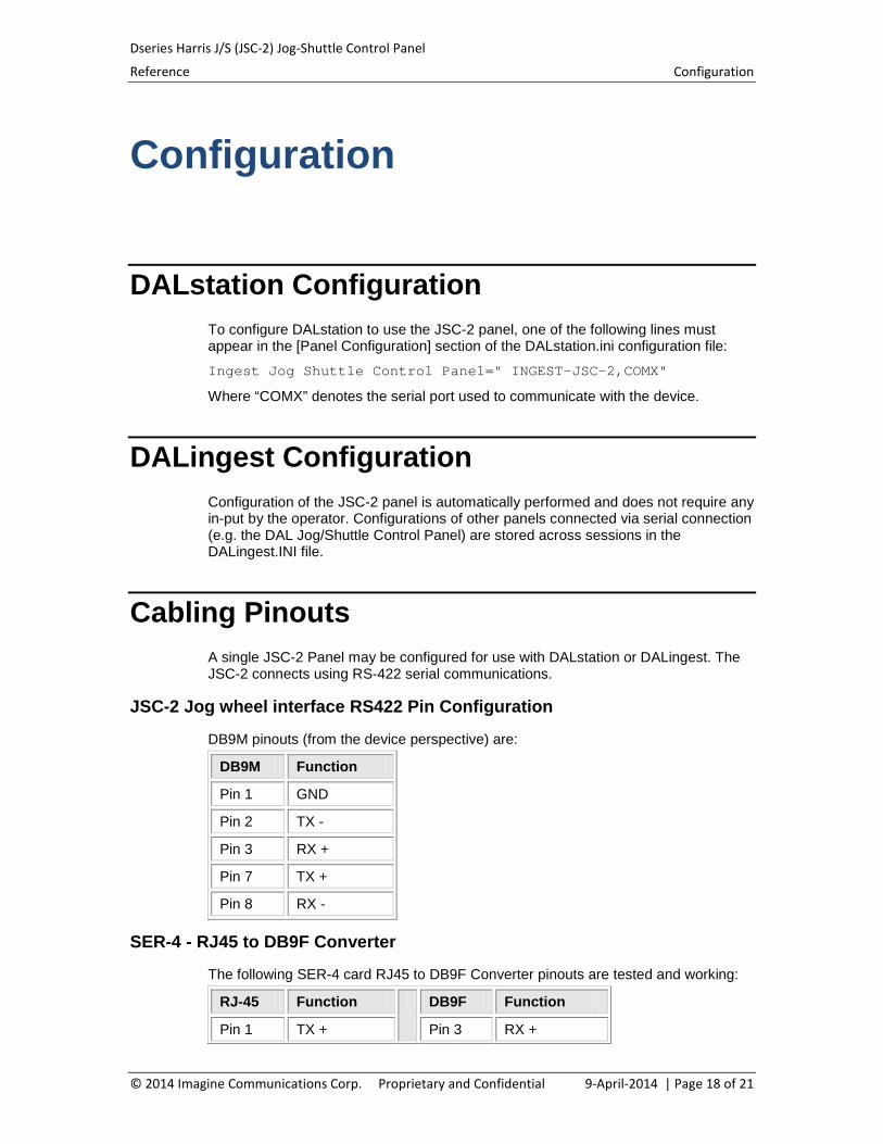
DALstation Configuration To configure DALstation to use the JSC-2 panel, one of the following lines must appear in the [Panel Configuration] section of the DALstation.ini configuration file:
Ingest Jog Shuttle Control Panel=" INGEST-JSC-2,COMX"
Where “COMX” denotes the serial port used to communicate with the device.
DALingest Configuration Configuration of the JSC-2 panel is automatically performed and does not require any in-put by the operator. Configurations of other panels connected via serial connection (e.g. the DAL Jog/Shuttle Control Panel) are stored across sessions in the DALingest.INI file.
Cabling Pinouts A single JSC-2 Panel may be configured for use with DALstation or DALingest. The JSC-2 connects using RS-422 serial communications.
JSC-2 Jog wheel interface RS422 Pin Configuration
DB9M pinouts (from the device perspective) are:
DB9M Function
Pin 1 GND
Pin 2 TX -
Pin 3 RX +
Pin 7 TX +
Pin 8 RX -
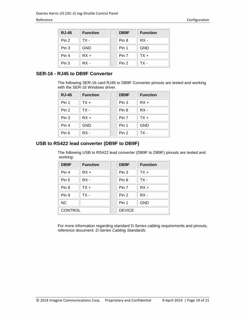
SER-4 - RJ45 to DB9F Converter
The following SER-4 card RJ45 to DB9F Converter pinouts are tested and working:
RJ-45 Function DB9F Function
Pin 1 TX + Pin 3 RX +
© 2014 Imagine Communications Corp. Proprietary and Confidential 9-April-2014 | Page 18 of 21
Dseries Harris J/S (JSC-2) Jog-Shuttle Control Panel
Reference Configuration
RJ-45 Function DB9F Function
Pin 2 TX - Pin 8 RX -
Pin 3 GND Pin 1 GND
Pin 4 RX + Pin 7 TX +
Pin 5 RX - Pin 2 TX -
SER-16 - RJ45 to DB9F Converter
The following SER-16 card RJ45 to DB9F Converter pinouts are tested and working with the SER-16 Windows driver.
RJ-45 Function DB9F Function
Pin 1 TX + Pin 3 RX +
Pin 2 TX - Pin 8 RX -
Pin 3 RX + Pin 7 TX +
Pin 4 GND Pin 1 GND
Pin 6 RX - Pin 2 TX -
USB to RS422 lead converter (DB9F to DB9F)
The following USB to RS422 lead converter (DB9F to DB9F) pinouts are tested and working:
DB9F Function DB9F Function
Pin 4 RX + Pin 3 TX +
Pin 5 RX - Pin 8 TX -
Pin 8 TX + Pin 7 RX +
Pin 9 TX - Pin 2 RX -
NC Pin 1 GND
CONTROL DEVICE
For more information regarding standard D-Series cabling requirements and pinouts, reference document: D-Series Cabling Standards.
© 2014 Imagine Communications Corp. Proprietary and Confidential 9-April-2014 | Page 19 of 21
Dseries Harris J/S (JSC-2) Jog-Shuttle Control Panel
Reference Unit Replacement
Unit Replacement
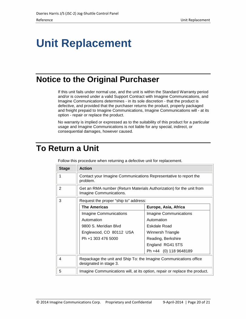
Notice to the Original Purchaser If this unit fails under normal use, and the unit is within the Standard Warranty period and/or is covered under a valid Support Contract with Imagine Communications, and Imagine Communications determines - in its sole discretion - that the product is defective, and provided that the purchaser returns the product, properly packaged and freight prepaid to Imagine Communications, Imagine Communications will - at its option - repair or replace the product.
No warranty is implied or expressed as to the suitability of this product for a particular usage and Imagine Communications is not liable for any special, indirect, or consequential damages, however caused.
To Return a Unit Follow this procedure when returning a defective unit for replacement.
Stage Action
1 Contact your Imagine Communications Representative to report the problem.
2 Get an RMA number (Return Materials Authorization) for the unit from Imagine Communications.
3 Request the proper “ship to” address: The Americas Europe, Asia, Africa Imagine Communications Automation 9800 S. Meridian Blvd Englewood, CO 80112 USA Ph +1 303 476 5000
Imagine Communications Automation Eskdale Road Winnersh Triangle Reading, Berkshire England RG41 5TS Ph +44 (0) 118 9648189
4 Repackage the unit and Ship To: the Imagine Communications office designated in stage 3.
5 Imagine Communications will, at its option, repair or replace the product.
© 2014 Imagine Communications Corp. Proprietary and Confidential 9-April-2014 | Page 20 of 21
Dseries Harris J/S (JSC-2) Jog-Shuttle Control Panel
Reference Unit Replacement
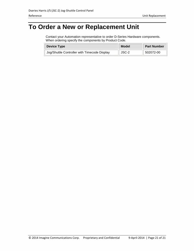
To Order a New or Replacement Unit Contact your Automation representative to order D-Series Hardware components. When ordering specify the components by Product Code.
Device Type Model Part Number
Jog/Shuttle Controller with Timecode Display JSC-2 502072-00
© 2014 Imagine Communications Corp. Proprietary and Confidential 9-April-2014 | Page 21 of 21


![A nemzetközi jog és a magyar jog viszonya - IJOTENA nemzetközi jog és a magyar jog kapcsolatának alkotmányos rendezése: történeti áttekintés [2] A nemzetközi jog és a](https://img.pdfslide.net/doc/110x75/5e5f750bbd9b2420976e197b/a-nemzetkzi-jog-s-a-magyar-jog-viszonya-ijoten-a-nemzetkzi-jog-s-a-magyar.jpg)