Embed Size (px)
Citation preview

Copyright 1995-1999 SCRA 1
Methodology
Reinv entingElectronic
DesignArchitecture Infrastructure
DARPA Tri-Service
RASSP
DSP Algorithm DesignRASSP Education & Facilitation Program
Module 23
Version 3.00
Copyright 1995-1999 SCRA
All rights reserved. This information is copyrighted by the SCRA, through its Advanced Technology Institute (ATI), andmay only
be used for non-commercial educational purposes. Any other use of this information without the express written permission of the
ATI is prohibited. Certain parts of this work belong to other copyright holders and are used with their permission. All information
contained, may be duplicated for non-commercial educational use only provided this copyright notice and the copyright
acknowledgements herein are included. No warranty of any kind is provided or implied, nor is any liability accepted regardless
of use.
The United States Government holds “Unlimited Rights” in all data contained herein under Contract F33615-94-C-1457. Such
data may be liberally reproduced and disseminated by the Government, in whole or in part, without restriction except as follows:
Certain parts of this work to other copyright holders and are used with their permission; This information contained herein may
be duplicated only for non-commercial educational use. Any vehicle, in which part or all of this data is incorporated into, shall
carry this notice .

Copyright 1995-1999 SCRA 2
Methodology
Reinv entingElectronic
DesignArchitecture Infrastructure
DARPA Tri-Service
RASSP Rapid Prototyping Design Process
Algorithm Design
SYSTEM
DEF.
FUNCTION
DESIGNHW & SW
PART.
HW
DESIGN
SW
DESIGN
HW
FAB
SW
CODE
INTEG.
& TEST
VIRTUAL PROTOTYPE
RASSP DESIGN LIBRARIES AND DATABASE
Primarily
software
Primarily
hardware
HW & SW
CODESIGN

Copyright 1995-1999 SCRA 3
Methodology
Reinv entingElectronic
DesignArchitecture Infrastructure
DARPA Tri-Service
RASSP
Module Goals
� State of the art survey in DSP algorithm design
� Convey RASSP-related contributions and impact
� Learn how to unambiguously state the specifications of DSP systems for later verification of the final implementation
� Learn about the various levels at which a DSP system can be simulated
� Learn how to link the higher level algorithm design to lower levels
� Know more about the different CAD tools which can be used at the above levels to automate the task of algorithm development and simulation
� Learn partitioning and codesign of the hardware and software components of DSP systems.

Copyright 1995-1999 SCRA 4
Methodology
Reinv entingElectronic
DesignArchitecture Infrastructure
DARPA Tri-Service
RASSP
Module Outline
� Introduction
� Requirements Capture
� Basic approach
� Requirements capture
� SAR application
� IRST application
� Requirements capture tool RDD-100 overview
� Code generation
� Viterbi decoder application
� Data generation
� Testbench simulation and control

Copyright 1995-1999 SCRA 5
Methodology
Reinv entingElectronic
DesignArchitecture Infrastructure
DARPA Tri-Service
RASSP
Module Outline (Cont.)
� Fixed-Point Design - A RASSP Approach
� Motivation for fixed-point processing
� Fixed-point representations
� Simple fixed point
� Generalized fixed point
� Examples
� VHDL fixed point modeling
� Fixed-point packages
� High level modeling of processors
� QuickFix environment
� Simulation-Based Algorithm/Functional Design
� Network-Level DSP
Copyright 1995-1999 SCRA 6
Methodology
Reinv entingElectronic
DesignArchitecture Infrastructure
DARPA Tri-Service
RASSP
Module Outline (Cont.)
� Link-Level DSP
� Signal Processing Simulators
� PGM/PGSE
� PGM/PGSE overview
� Application development in PGM
� Issues in the use of PGM
� RASSP Software Generation
� Summary
Copyright 1995-1999 SCRA 7
Methodology
Reinv entingElectronic
DesignArchitecture Infrastructure
DARPA Tri-Service
RASSP
Module Outline
� Introduction
� Requirements Capture
� Fixed-Point Design - A RASSP Approach
� Simulation-Based Algorithm/Functional Design
� Network-Level DSP
� Link-Level DSP
� Signal Processing Simulators
� PGM/PGSE
� RASSP Software Generation
� Summary

Copyright 1995-1999 SCRA 8
Methodology
Reinv entingElectronic
DesignArchitecture Infrastructure
DARPA Tri-Service
RASSP
Introduction
� The complexity of Signal Processing/ Communication Systems algorithms has grown enormously
� The time-to-market requirements have reduced considerably
� There is a mismatch and dichotomy between algorithm development & design and algorithm implementation
CONFLICTING REQUIREMENTS
Copyright 1995-1999 SCRA 9
Methodology
Reinv entingElectronic
DesignArchitecture Infrastructure
DARPA Tri-Service
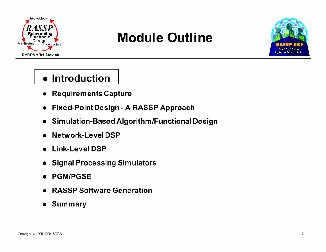
RASSP Conventional Approach vs RASSP Approach
AlgorithmDesign
Implementation
AlgorithmDesign Implementation
Conventional Approach
RASSP Approach

Copyright 1995-1999 SCRA 10
Methodology
Reinv entingElectronic
DesignArchitecture Infrastructure
DARPA Tri-Service
RASSP
Trends in Algorithm Design
� New technologies are emerging� Need to integrate networking, transmission,
sensors, data and signal processing� Mission requirements are changing and
becoming flexible� Numerical and storage requirements are growing� There is often inadequate information on nature
of data� There is little reuse of part designs (beyond
organizational barriers)� Approach has been to REUSE the designer
� There is no automation at higher levels of abstraction
� Work is done by multi-person teams of designers and implementation experts

Copyright 1995-1999 SCRA 11
Methodology
Reinv entingElectronic
DesignArchitecture Infrastructure
DARPA Tri-Service
RASSP Requirements of RASSP Algorithm Development
Environment
� Model, analyze, design, and test large systems (at multiple levels of abstraction)
� Allow rapid exploration of a variety of reuse-based sources
� Link the algorithm design environment to lower levels of abstraction
� Continue HW/SW modeling and use real data to produce effective designs
� Allow efficient multi-person team collaboration (product, design, and management teams)

Copyright 1995-1999 SCRA 12
Methodology
Reinv entingElectronic
DesignArchitecture Infrastructure
DARPA Tri-Service
RASSP
Module Outline
� Introduction
� Requirements capture
� Fixed-Point Design - A RASSP Approach
� Simulation-Based Algorithm/Functional Design
� Network-Level DSP
� Link-Level DSP
� Signal Processing Simulators
� PGM/PGSE
� RASSP Software Generation
� Summary

Copyright 1995-1999 SCRA 13
Methodology
Reinv entingElectronic
DesignArchitecture Infrastructure
DARPA Tri-Service
RASSP
Section Outline
� Requirements Capture
� Basic approach
� Requirements capture
� Code generation
� Data generation
� Testbench simulation and control
Copyright 1995-1999 SCRA 14
Methodology
Reinv entingElectronic
DesignArchitecture Infrastructure
DARPA Tri-Service
RASSP
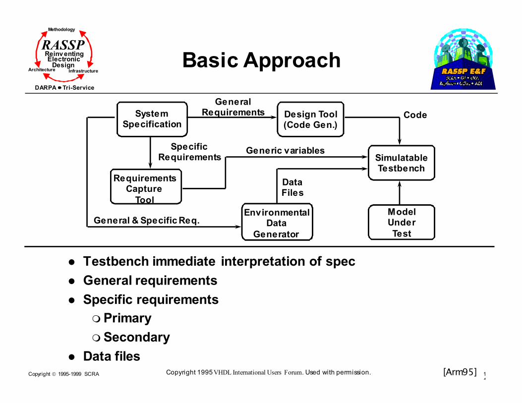
Basic Approach
� Testbench immediate interpretation of spec
� General requirements
� Specific requirements
� Primary
� Secondary
� Data files
SystemSpecification
GeneralRequirements
SpecificRequirements
RequirementsCapture
Tool
Generic variables
EnvironmentalData
Generator
General & Specific Req.
DataFiles
Design Tool(Code Gen.)
SimulatableTestbench
ModelUnder
Test
Code
[Arm95]Copyright 1995 VHDL International Users Forum. Used with permission.
Copyright 1995-1999 SCRA 15
Methodology
Reinv entingElectronic
DesignArchitecture Infrastructure
DARPA Tri-Service
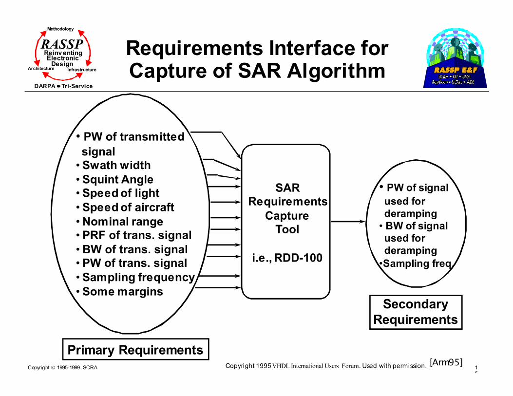
RASSP Requirements Interface for Capture of SAR Algorithm
SARRequirements
CaptureTool
i.e., RDD-100
• PW of transmitted
signal• Swath width
• Squint Angle• Speed of light
• Speed of aircraft
•Nominal range• PRF of trans. signal
•BW of trans. signal• PW of trans. signal
• Sampling frequency
• Some margins
Primary Requirements
Secondary
Requirements
• PW of signal
used for
deramping
• BW of signal
used for
deramping
•Sampling freq.
[Arm95]Copyright 1995 VHDL International Users Forum. Used with permission.

Copyright 1995-1999 SCRA 16
Methodology
Reinv entingElectronic
DesignArchitecture Infrastructure
DARPA Tri-Service
RASSP Requirements Interfacefor Capture of IRSTAlgorithm (Cont.)
IRSTRequirements
CaptureTool
RDD-100
• Target Speed
• Platform Type• Sensor Resolution
•Revisit Period•Range
•Bars per frame
• Field of View
Primary Requirements
Secondary
Requirements
• Target Motion
• Clutter Motion
[Arm95]Copyright 1995 VHDL International Users Forum. Used with permission.

Copyright 1995-1999 SCRA 17
Methodology
Reinv entingElectronic
DesignArchitecture Infrastructure
DARPA Tri-Service
RASSP Math Model for IRST Requirements Interface
Platform Displacement (PD)
a1 a2
Range 1 Range 2
Clutter
[Arm95]Copyright 1995 VHDL International Users Forum. Used with permission.

Copyright 1995-1999 SCRA 18
Methodology
Reinv entingElectronic
DesignArchitecture Infrastructure
DARPA Tri-Service
RASSP RDD-100:Definition Overview
� Behavior diagram
� Graphical representation of behavior of functions in terms of time-flow sequence
� Function
� Part of system that carries out an action, usually converting an input to an output
� Item
� Something a function accepts or produces (i.e., I/O)
� Discrete function
� Function at lowest level of detail w/o subfunctions
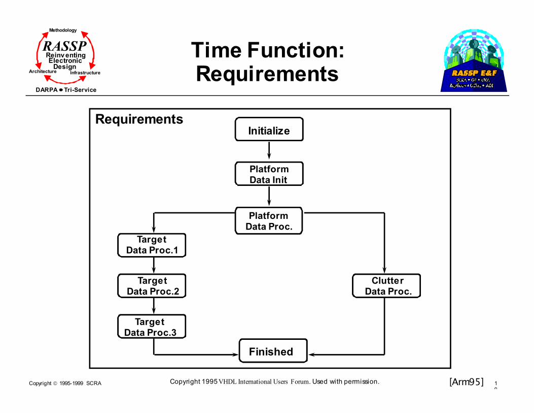
� Time function
� Higher-level function which can have discrete functions and/or time functions as sub-functions
Copyright 1995-1999 SCRA 19
Methodology
Reinv entingElectronic
DesignArchitecture Infrastructure
DARPA Tri-Service
RASSP Time Function:Requirements
RequirementsInitialize
PlatformData Init
PlatformData Proc.
TargetData Proc.1
TargetData Proc.2
TargetData Proc.3
ClutterData Proc.
Finished
[Arm95]Copyright 1995 VHDL International Users Forum. Used with permission.

Copyright 1995-1999 SCRA 20
Methodology
Reinv entingElectronic
DesignArchitecture Infrastructure
DARPA Tri-Service
RASSP Modeling Views of Reactive Systems - i-Logix STATEMATE
Functional View(what)
Dataflow
Behavioral View(when)
Control & Timing
Conceptual
Structural View(how)
Modules & Comm. links
Physical

Copyright 1995-1999 SCRA 21
Methodology
Reinv entingElectronic
DesignArchitecture Infrastructure
DARPA Tri-Service
RASSP
Functional Activity Charts
Get Input
Set Up
ProcessSignal Compare
DisplayFault
Sensor
Operator
SAMPLE
Raw
Signal
Alarm
Copyright 1995-1999 SCRA 22
Methodology
Reinv entingElectronic
DesignArchitecture Infrastructure
DARPA Tri-Service
RASSP
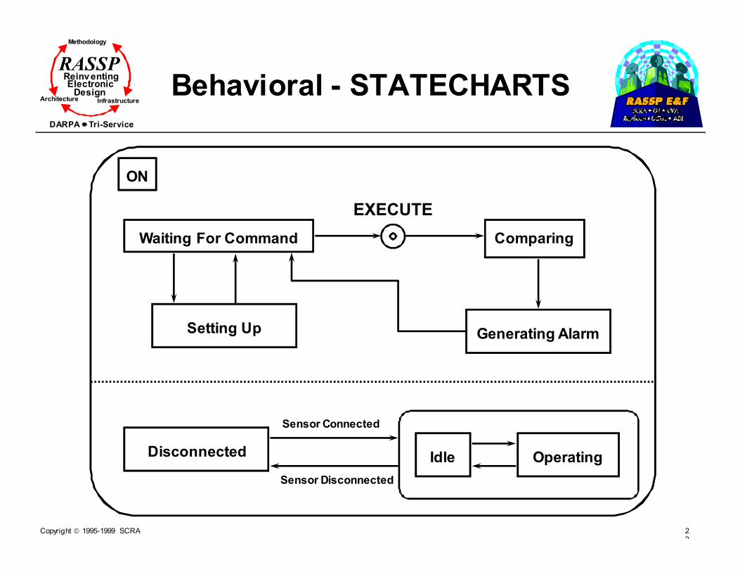
Behavioral - STATECHARTS
ON
Waiting For Command Comparing
Generating AlarmSetting Up
Disconnected Idle Operating
Sensor Connected
Sensor Disconnected
EXECUTE

Copyright 1995-1999 SCRA 23
Methodology
Reinv entingElectronic
DesignArchitecture Infrastructure
DARPA Tri-Service
RASSP
Structural - Module Charts
Keyboard
Screen
CCU
Alarm
DSPPrinter
Operator
Sensor
Messages
Copyright 1995-1999 SCRA 24
Methodology
Reinv entingElectronic
DesignArchitecture Infrastructure
DARPA Tri-Service
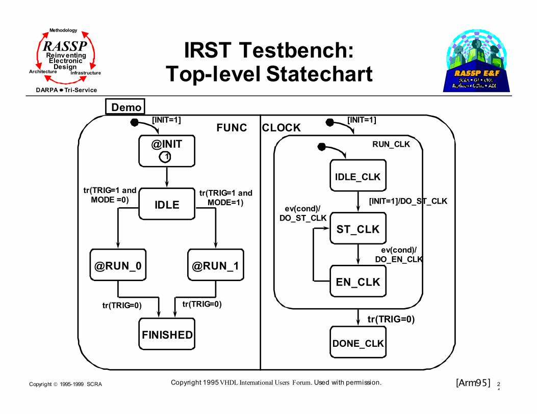
RASSP IRST Testbench:Top-level Statechart
Demo
FUNC CLOCK
@INIT1
IDLE
@RUN_0 @RUN_1
FINISHED
tr(TRIG=1 andMODE =0)
tr(TRIG=1 andMODE=1)
tr(TRIG=0) tr(TRIG=0)
[INIT=1] [INIT=1]
RUN_CLK
IDLE_CLK
[INIT=1]/DO_ST_CLK
ST_CLK
EN_CLK
DONE_CLK
tr(TRIG=0)
ev(cond)/DO_ST_CLK
ev(cond)/DO_EN_CLK
[Arm95]Copyright 1995 VHDL International Users Forum. Used with permission.

Copyright 1995-1999 SCRA 25
Methodology
Reinv entingElectronic
DesignArchitecture Infrastructure
DARPA Tri-Service
RASSP SAR Testbench:Activity Chart Model
BW SAMP_FREQ FREQ PW PRF N
Environment
SAR-TB
Chirp
Comptfp1
Comptfp2
CompMul1
CompMul2
CompMul3
CompMul4
CompMul5
Neg2
Neg3
Neg4
Neg5Comptfp5
CompMul6
Comptfp3
Assign1
DeciMat1
DeciMat2
Change1
Change2
Change3
Change4
Assign2
RC1
IC1
RC2
IC2
R2
I2
R1
I1
NR2
NI2
DR1
DI1
R6
I6
NR6
NI6
R7
I7
R4
I4
R3
I3
NR3
NI3
R5
I5
NR4 NI4
RRH1
IRH1
VRRH
VIRH
VRBH
VIBH
VIBV
VRBV
RRV1
IRV1
VRRV
VIRV
[Arm95]Copyright 1995 VHDL International Users Forum. Used with permission.

Copyright 1995-1999 SCRA 26
Methodology
Reinv entingElectronic
DesignArchitecture Infrastructure
DARPA Tri-Service
RASSP
Code Generation
� Two main approaches
� Behavioral testbench development
� Uses CASE tools to develop high-level models (i.e., i-Logix Express VHDL)
� Statecharts and activity charts describe behavior
� Advantages include
�Reduced test time required for large models
�Testbenches can be used for a class of systems which have same general functionality
�No detailed internal structure required
� Structural testbench development
� Uses schematic capture tools to construct the testbench from library of primitives
� Advantage
�Uses existing commercial schematic capture tools

Copyright 1995-1999 SCRA 27
Methodology
Reinv entingElectronic
DesignArchitecture Infrastructure
DARPA Tri-Service
RASSP Behavioral Specs. - Viterbi Decoder
Modulator
Encoder
Channel De-modulator
Quantizer
Decoder
x[n]
y0[n], y1[n]
s[n] sn[n]Analog r0[n], r1[n]
r0[n], r1[n]
y0’[n], y1’[n], x’[n]
(0,1)
(0,1)
(-1,1) Real #’s
Real #’s
(0,1)
(0,1)

Copyright 1995-1999 SCRA 28
Methodology
Reinv entingElectronic
DesignArchitecture Infrastructure
DARPA Tri-Service
RASSP
Linear Convolutional Encoder
Delayx[n]
y0[n]
y1[n]
x[n-1]x[n-2]Delay

Copyright 1995-1999 SCRA 29
Methodology
Reinv entingElectronic
DesignArchitecture Infrastructure
DARPA Tri-Service
RASSP
VHDL Code for the Encoder
ARCHITECTURE fsmd OF encoder IS
BEGIN
PROCESS (clock)
VARIABLE state : integer RANGE 0 to 3 := 0;
BEGIN
IF rising edge of the clock THEN
CASE state IS
Set the next state and the two outputs
depending on the present state and the
input
END CASE;
END IF; User defined variables are
END PROCESS; underlined. Key words are
END fsmd; in capitals.
Copyright 1995-1999 SCRA 30
Methodology
Reinv entingElectronic
DesignArchitecture Infrastructure
DARPA Tri-Service
RASSP
BPSK Modulator
� Convert parallel output of encoder to serial
� Send y0[n] at the rising clock edge
� Send y1[n] at the falling clock edge
� Transmit
� -1 to represent a 0
� +1 to represent a 1

Copyright 1995-1999 SCRA 31
Methodology
Reinv entingElectronic
DesignArchitecture Infrastructure
DARPA Tri-Service
RASSP
VHDL for the Modulator
ARCHITECTURE behavior OF bpsk IS
BEGIN
PROCESS (clock)
BEGIN
IF rising edge of the clock THEN
If first input = 1 then transmit a +1
if it is 0 then transmit a -1
ELSIF falling edge of the clock THEN
If second input = 1 then transmit a +1
if it is 0 then transmit a -1
END PROCESS;
END behavior;

Copyright 1995-1999 SCRA 32
Methodology
Reinv entingElectronic
DesignArchitecture Infrastructure
DARPA Tri-Service
RASSP
AWGN Channel
� Signal to Noise Ratio (SNR) and Variance
SNR = -10 log10N0
Variance = σσσσ 2222 = N0
Therefore, σ σ σ σ = 10-(SNR/20)
� Gaussian Noise Generation
x1 = exp(- (y12+y22)/2)
x2 = (arctan(y2/y1)) / (2ππππ)
� Choose x1 and x2 to be Uniform random variables over (-1,1)
� Then y1 and y2 are Gaussian random variables with mean 0 and variance 1
� Scale y1 and y2 to get the right variance
Copyright 1995-1999 SCRA 33
Methodology
Reinv entingElectronic
DesignArchitecture Infrastructure
DARPA Tri-Service
RASSP
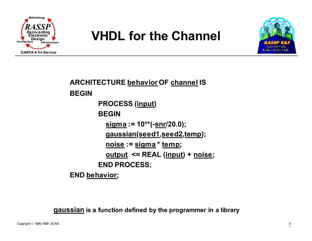
VHDL for the Channel
ARCHITECTURE behavior OF channel IS
BEGIN
PROCESS (input)
BEGIN
sigma := 10**(-snr/20.0);
gaussian(seed1,seed2,temp);
noise := sigma * temp;
output <= REAL (input) + noise;
END PROCESS;
END behavior;
gaussian is a function defined by the programmer in a library

Copyright 1995-1999 SCRA 34
Methodology
Reinv entingElectronic
DesignArchitecture Infrastructure
DARPA Tri-Service
RASSP
3-bit Quantizer
� 3-bits => 8 levels
-0.9 -0.7 -0.3 0 0.3 0.7 0.9
3
2
1
-1
-2
-3
-4
Input
Output
No need to express the output
in terms of bits since the Viterbi
algorithm simply looks for the
Euclidean distance between the
signals

Copyright 1995-1999 SCRA 35
Methodology
Reinv entingElectronic
DesignArchitecture Infrastructure
DARPA Tri-Service
RASSP
VHDL for the Quantizer
ARCHITECTURE behavior OF quantizer IS
BEGIN
PROCESS (clock)
BEGIN
IF event on the clock THEN
Depending on the range in which the
input lies decide the output
IF rising edge of the clock THEN
actually send the output
IF falling edge of the clock THEN
update the internal registers
END IF;
END PROCESS;
END behavior;

Copyright 1995-1999 SCRA 36
Methodology
Reinv entingElectronic
DesignArchitecture Infrastructure
DARPA Tri-Service
RASSP
Feedback to update Path metric
Viterbi Decoder Using the Register Exchange Method
� Maximum Likelihood Sequence Estimation (MLSE)
� Most efficient decoder for convolutional codes
� Applications
� High performance equalizer for mobile communication
� TCM decoder for V.32 modem
� Implementation Structure
Branch Metric
Computation
Add Compare
SelectSurvivor
Memory
r0
r1x’[n]

Copyright 1995-1999 SCRA 37
Methodology
Reinv entingElectronic
DesignArchitecture Infrastructure
DARPA Tri-Service
RASSP
VHDL for the Viterbi Decoder
ARCHITECTURE behavior OF quantizer IS
BEGIN
PROCESS (clock)
BEGIN
Delay activation of the decoder till the first sample
reaches it
IF rising edge of the clock and THEN
Calculate branch metrics using inner
products between the received word and
the code word
Compare and select the surviving path
Exchange register contents
END IF;
END PROCESS;
END behavior;
Copyright 1995-1999 SCRA 38
Methodology
Reinv entingElectronic
DesignArchitecture Infrastructure
DARPA Tri-Service
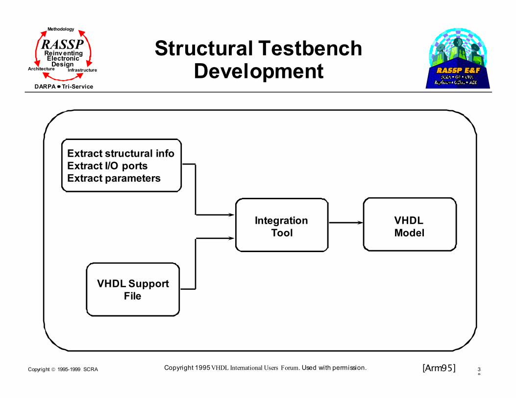
RASSP Structural Testbench Development
Extract structural info
Extract I/O ports
Extract parameters
VHDL Support
File
Integration
Tool
VHDL
Model
[Arm95]Copyright 1995 VHDL International Users Forum. Used with permission.

Copyright 1995-1999 SCRA 39
Methodology
Reinv entingElectronic
DesignArchitecture Infrastructure
DARPA Tri-Service
RASSP
Data Generation
� Comdisco/Cadence SPW, xpatch, or Matlab used to generated data files for model under test
� SPW uses “sink” primitive to dump to file in ascii format
� xpatch used to generate radar sensor data files
� Matlab used to generate clutter file data

Copyright 1995-1999 SCRA 40
Methodology
Reinv entingElectronic
DesignArchitecture Infrastructure
DARPA Tri-Service
RASSP Testbench Simulation & Control System
Requirements
Capture
Tool
Inputs from
User
Environmental
Data
Generator
Data
Files
Intelligent
User
Interface
(IUI)
in C
i-Logix
Express VHDL
Behavioral
Model for
Testbench
Final
Simulation
Control
File
Synopsis
Graphical
Environment
Structural
Model for
Testbench
SPW
Schematic
Capture
Tool
Synopsis
VHDL
Simulator
(vhdlsim)
VHDL
Model
Under
Test
Comparator
[Arm95]Copyright 1995 VHDL International Users Forum. Used with permission.

Copyright 1995-1999 SCRA 41
Methodology
Reinv entingElectronic
DesignArchitecture Infrastructure
DARPA Tri-Service
RASSP Intelligent User InterfaceMenu Structure
IUI
RequirementsDriven
(for IRST)
Type ofTestbench
Mode ofProcessing
UserDriven
ApplicationDomain
Type ofTestbench
Mode ofProcessing
[Arm95]Copyright 1995 VHDL International Users Forum. Used with permission.
Copyright 1995-1999 SCRA 42
Methodology
Reinv entingElectronic
DesignArchitecture Infrastructure
DARPA Tri-Service
RASSP
Module Outline
� Introduction
� Requirements Capture
� Fixed-Point Design - A RASSP Approach
� Simulation-Based Algorithm/Functional Design
� Network-Level DSP
� Link-Level DSP
� Signal Processing Simulators
� PGM/PGSE
� RASSP Software Generation
� Summary
Copyright 1995-1999 SCRA 43
Methodology
Reinv entingElectronic
DesignArchitecture Infrastructure
DARPA Tri-Service
RASSP
Section Outline
� Fixed-Point Design
� Motivation for fixed-point processing
� Fixed-point representations
� Simple fixed point
� Generalized fixed point
� Examples
� VHDL fixed point modeling
� Fixed-point packages
� High level modeling of processors
� QuickFix environment
Copyright 1995-1999 SCRA 44
Methodology
Reinv entingElectronic
DesignArchitecture Infrastructure
DARPA Tri-Service
RASSP
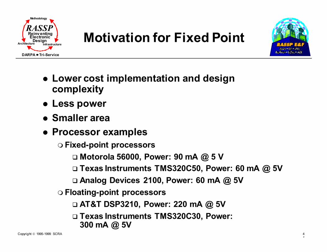
Motivation for Fixed Point
� Lower cost implementation and design complexity
� Less power
� Smaller area
� Processor examples
� Fixed-point processors
� Motorola 56000, Power: 90 mA @ 5 V
� Texas Instruments TMS320C50, Power: 60 mA @ 5V
� Analog Devices 2100, Power: 60 mA @ 5V
� Floating-point processors
� AT&T DSP3210, Power: 220 mA @ 5V
� Texas Instruments TMS320C30, Power: 300 mA @ 5V

Copyright 1995-1999 SCRA 45
Methodology
Reinv entingElectronic
DesignArchitecture Infrastructure
DARPA Tri-Service
RASSP
Fixed-point Representations
� Simple fixed point� Field of bits with radix point on bit boundary
� Power of 2 scaling
� Notation: fix<x.y>
� Integer form: Radix point to right of LSB
� Fractional form: Radix point one bit to right of MSB (sign bit)
� Generalized fixed point� Radix point not necessarily on bit boundary
� Integral (exact) and fractional (approximate) forms
� Notation: Integral form
� ix∆∆∆∆x where ix is the integral field and ∆∆∆∆x is the stepsize
� Notation: Fractional form
� ααααxφφφφx where ααααx is the fractional field and φφφφx is the fieldsize
Copyright 1995-1999 SCRA 46
Methodology
Reinv entingElectronic
DesignArchitecture Infrastructure
DARPA Tri-Service
RASSP
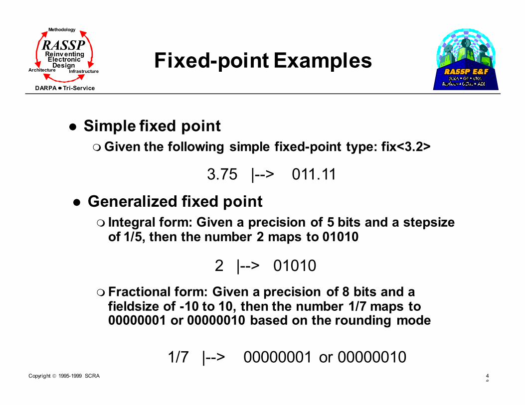
Fixed-point Examples
� Simple fixed point
� Given the following simple fixed-point type: fix<3.2>
3.75 |--> 011.11
� Generalized fixed point
� Integral form: Given a precision of 5 bits and a stepsize of 1/5, then the number 2 maps to 01010
2 |--> 01010
� Fractional form: Given a precision of 8 bits and a fieldsize of -10 to 10, then the number 1/7 maps to 00000001 or 00000010 based on the rounding mode
1/7 |--> 00000001 or 00000010

Copyright 1995-1999 SCRA 47
Methodology
Reinv entingElectronic
DesignArchitecture Infrastructure
DARPA Tri-Service
RASSP VHDL Fixed-point:High-level Modeling
� VHDL has two basic data types (scalar and composite)
� Numeric (Integer and Real)
� Enumeration (boolean, bit, and character)
� Physical (time)
� Fixed-point packages to perform specific calculations
� Overloaded operators
package BIT_16pack is
type FIX16 is
record
field : real;
frac : integer;
end record
function “+” (op1 : FIX16;
op2 : FIX16) return FIX16;
function “*” (op1 : FIX16;
op2 : FIX16) return FIX16;
function “-” (op1 : FIX16;
op2 : FIX16) return FIX16;
function “/” (op1 : FIX16;
op2 : FIX16) return FIX16;
end BIT_16pack;
[Egolf]© IEEE 1995

Copyright 1995-1999 SCRA 48
Methodology
Reinv entingElectronic
DesignArchitecture Infrastructure
DARPA Tri-Service
RASSP VHDL Processor-specificHigh-level Modeling
� Package expresses the functionality of the processor to be modeled
� Important functionality
� Adder and multiplier input and output widths
� Accumulator sizes
� Shifter functionality
� Rounding/Truncation and overflow properties
package ADSP2100pack isfunction “+” (op1 : BIT_16;
op2 : BIT_16) return BIT_16;
function MULT (op1 : integer;
op2 : integer;
mode: string) return BIT_40;function RND (op1 : BIT_32) return integer;
function TRUNC (op1 : BIT_32) return integer;
function ADD_40 (ad1 : BIT_40;
ad2 : BIT_40) return BIT_40;
function MAC (accum : BIT_40;mp1 : integer;
mp2 : integer;
mode : string) return BIT_40;
function GET_EXP (op1 : BIT_VECTOR)
return integer;function NORMALIZE (op1 : BIT_VECTOR;
shift: integer);
return BIT_32;
end ADSP2100pack;
[Egolf]© IEEE 1995

Copyright 1995-1999 SCRA 49
Methodology
Reinv entingElectronic
DesignArchitecture Infrastructure
DARPA Tri-Service
RASSP
QuickFix Environment
QuickFix Environment
Technology Independent Technology Dependent ASIC
TMS320C50 ADSP2100 ASIC
CELP, JPEG, etc. ADSP2100, TMS320C50, etc.
Floating-point solutionCompare Metrics
Technology Selection
Implementation
Verification
[Egolf]
© IEEE 1995
Copyright 1995-1999 SCRA 50
Methodology
Reinv entingElectronic
DesignArchitecture Infrastructure
DARPA Tri-Service
RASSP
Module Outline
� Introduction
� Requirements Capture
� Fixed-Point Design - A RASSP Approach
� Simulation-Based Algorithm/Functional Design
� Network-Level DSP
� Link-Level DSP
� Signal Processing Simulators
� PGM/PGSE
� RASSP Software Generation
� Summary

Copyright 1995-1999 SCRA 51
Methodology
Reinv entingElectronic
DesignArchitecture Infrastructure
DARPA Tri-Service
RASSP Simulation-based vs Analytical Approach
� SIMPLE or COMPLEX (as required by application)
� FAST to SLOW (tailored by application)
� Finely explore the design space
� Very accurate, if necessary
� Combines mathematical & empirical models
� Intermediate & transient state available
� Testing
� SIMPLE to use (formula)
� FAST
� Generally APPROXIMATE (assumptions usually artificial)
� DIFFICULT to analyze COMPLEX systems
� Usually specific to application -- little reuse
Simulation-based Approach Analytical Approach

Copyright 1995-1999 SCRA 52
Methodology
Reinv entingElectronic
DesignArchitecture Infrastructure
DARPA Tri-Service
RASSP Trends in Simulations/Tools and Environments
� 1970s - Individual programs
� Batch mode execution on mainframes
� Outputs consist of tables and numbers
� Considerable time on debugging and less time on application
� 1980s - Simulation environments and languages
� Model libraries
� Interoperability
� Computer-aided design and analysis
� Better user interfaces
� Distributed and parallel environments
� Advanced database management

Copyright 1995-1999 SCRA 53
Methodology
Reinv entingElectronic
DesignArchitecture Infrastructure
DARPA Tri-Service
RASSP Trends in Simulations/Tools and Environments (Cont.)
� 1990s - Managing simulation complexity, inter-operability, and reuse (little programming required, if any)
� Hierarchical simulation and Block-oriented
� Mixed domains of computation and interaction
� Larger application-specific focus
� Simulation and verification
� Automation
� Links to lower levels of abstraction

Copyright 1995-1999 SCRA 54
Methodology
Reinv entingElectronic
DesignArchitecture Infrastructure
DARPA Tri-Service
RASSP Hierarchical Approach to DSP Design
Wide dynamic range in complexity:
Custom Chips Large distributed multi-
processor systems
NETWORK Level
LINK Level
Signal
Processing
EVENT-DRIVEN
WAVEFORM / TIME DRIVEN
•Channel, Modulation
formats, etc.
TIME-DRIVEN• Signal Processing
(SNR, finite-precision, etc.)
[Shanmugan89]© IEEE 1989

Copyright 1995-1999 SCRA 55
Methodology
Reinv entingElectronic
DesignArchitecture Infrastructure
DARPA Tri-Service
RASSP Hierarchical Approach to DSP Design (Cont.)
� NETWORK LAYER
� Performance of network in terms of throughput and error rates as functions of load, protocols, and data distribution
� Usually event-driven
� LINK Level
� Physical level, including modulation and data formats, modem, filter bandwidths, effects of noise, and interference
� Usually time-driven
� Signal Processing Level
� Alternate algorithms for application-specific image/signal processing, finite precision effects, limitations of computational power and approximate processing, SW/HW design trade-offs
� Usually time-driven (clocked)
Data
Data

Copyright 1995-1999 SCRA 56
Methodology
Reinv entingElectronic
DesignArchitecture Infrastructure
DARPA Tri-Service
RASSP Major Structural Features of Design and Analysis
Environments
Block-oriented (graphical) or Language Description
SYSTEM CONFIGURATOR
Simulation Exerciser
Post Processor(Simulation Interpretation)
REUSE MODEL LIBRARIES
Model & SystemParameters
NewTopology
NewParameters
Performance output results[Shanmugan88]
© IEEE 1989

Copyright 1995-1999 SCRA 57
Methodology
Reinv entingElectronic
DesignArchitecture Infrastructure
DARPA Tri-Service
RASSP
Functional Tasks
� System Configurator� Selects functional blocks from model library
� Connects them in the desired topology
� Can set parameters
� Simulation Exerciser� Sets up the execution of the simulation
� Schedules, assigns, and allocates resources
� Generates and uses testbenches
� Performs checkpointing and storage of simulation state
� Performs garbage collection and recovery
� Post Processor� Examines time & event histories
� Computes performance metrics
� Formats and displays interpreted results
� Decides on the termination conditions (iterations)

Copyright 1995-1999 SCRA 58
Methodology
Reinv entingElectronic
DesignArchitecture Infrastructure
DARPA Tri-Service
RASSP Simulation Inputs(Graphical and Language)
� Preferred approach - functional blocks/package to be written in C & FORTRAN
� Do not allow input via block diagram (engineer’s approach)
� Special-purpose Simulation languages that are portable across various computing platforms
� E.g.: SIMSCRIPT, GPSS, SLAM, SIMULA, VHDL
� Graphical Languages such as:
� Statemate/Statechart
� PGM/PGSE environments
� Ptolemy
� Blosim
� Comdisco (SPW, BOSS, BONES)
� COSSAP
Copyright 1995-1999 SCRA 59
Methodology
Reinv entingElectronic
DesignArchitecture Infrastructure
DARPA Tri-Service
RASSP Features Required from an Input Language
� Training Required
� Ease of learning the language
� Ease of conceptualizing design problems
� Ease of programming
� Coding Considerations
� Integration
� Degree to which code is self-documenting
� Portability
� Language availability on various platforms
� Flexibility
� Supports various modeling domains
� Statistics/metric calculation capabilities
� List/queue processing capabilities
Copyright 1995-1999 SCRA 60
Methodology
Reinv entingElectronic
DesignArchitecture Infrastructure
DARPA Tri-Service
RASSP Features Required from an Input Language (Cont.)
� Processing Considerations
� Ease of producing reports
� Ease of user-interface usage
� Debugging Capabilities
� Ease of debugging
� Reliability and efficiency of compilers
� Run-time Considerations
� Execution speed
� Memory management
� Concurrency extraction

Copyright 1995-1999 SCRA 61
Methodology
Reinv entingElectronic
DesignArchitecture Infrastructure
DARPA Tri-Service
RASSP
Other Functional Components
� Model Library
� Contains large number of validated models of functional behavior
� Should be capable of being expanded by user
� Provides inter-operability and standardized interfaces
� Model Builder
� Selects building blocks
� Sets parameter values
� Operates at schematic capture-level
� Is hierarchical
� Eliminates programming by user
� Simulation Manager
� Translates model to executable program
� Links to libraries
� Assigns, schedules, and allocates resources
� Performs database management
Free the Algorithm Developer from
burdensome tasks

Copyright 1995-1999 SCRA 62
Methodology
Reinv entingElectronic
DesignArchitecture Infrastructure
DARPA Tri-Service
RASSP
Module Outline
� Introduction
� Requirements Capture
� Fixed-Point Design - A RASSP Approach
� Simulation-Based Algorithm/Functional Design
� Network-Level DSP
� Link-Level DSP
� Signal Processing Simulators
� PGM/PGSE
� RASSP Software Generation
� Summary

Copyright 1995-1999 SCRA 63
Methodology
Reinv entingElectronic
DesignArchitecture Infrastructure
DARPA Tri-Service
RASSP
Network-level CAD Tools
� Analytic tools
� Simulation tools - most powerful
� Emulation tools & testbeds (usually for testing protocols)
� Focus on a NETWORK-LEVEL simulator
� Finite state machines and Petri nets
� Queuing theory
� Collection of interacting procedures (SIMULA, GPSS)
� Network design and modeling consists of three major tasks
� Protocol Design and Test - majority of the work
� Topology (physical)
� Processing nodes (attributes)

Copyright 1995-1999 SCRA 64
Methodology
Reinv entingElectronic
DesignArchitecture Infrastructure
DARPA Tri-Service
RASSP
Network Level CAD Tools
Protocol Design & Verification: Petri nets
Computer
Idle
Terminal
Ready
Computer
BusyExample of interaction with
a KEYBOARD
Token
Directed Arc
Trigger
PlaceSource
[Jackman88]© IEEE 1988
Copyright 1995-1999 SCRA 65
Methodology
Reinv entingElectronic
DesignArchitecture Infrastructure
DARPA Tri-Service
RASSP
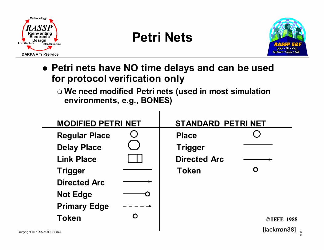
Petri Nets
� Petri nets have NO time delays and can be used for protocol verification only
� We need modified Petri nets (used in most simulation environments, e.g., BONES)
MODIFIED PETRI NET STANDARD PETRI NET
Regular Place Place
Delay Place Trigger
Link Place Directed Arc
Trigger Token
Directed Arc
Not Edge
Primary Edge
Token
[Jackman88]
© IEEE 1988

Copyright 1995-1999 SCRA 66
Methodology
Reinv entingElectronic
DesignArchitecture Infrastructure
DARPA Tri-Service
RASSP
Petri Nets (Cont.)
INTERRUPTED DELAY
- Start of Transmission
- End of Transmission
- Message Arrival
SOT
EOT
Arrive
[Jackman88]© IEEE 1988
Copyright 1995-1999 SCRA 67
Methodology
Reinv entingElectronic
DesignArchitecture Infrastructure
DARPA Tri-Service
RASSP
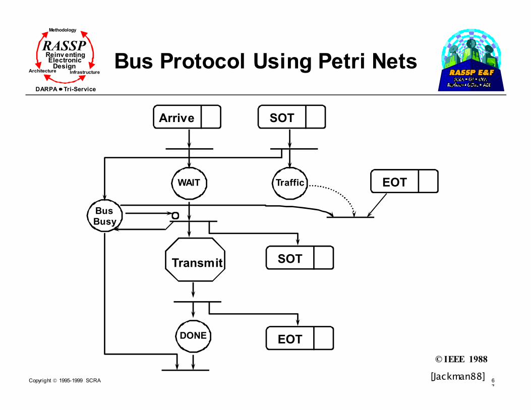
Bus Protocol Using Petri Nets
Arrive SOT
WAIT Traffic EOT
Transmit SOT
DONE EOT
BusBusy
[Jackman88]
© IEEE 1988

Copyright 1995-1999 SCRA 68
Methodology
Reinv entingElectronic
DesignArchitecture Infrastructure
DARPA Tri-Service
RASSP
Detailed Example
� Topology
� Physical connections
� Propagation velocity of the medium
� Transmission rate of the medium
� Transmission type
� Node
� Arrival distribution of packets
� Packet-length distribution
� Location of node on the network
� Traffic pattern
� Protocol
� Routing table for source/sink configuration
2µµµµs 2µµµµs propagation
delay
From/To 1 2 3
1 4
2 4
3 6
delay in µµµµs
[Jackman88]© IEEE 1988

Copyright 1995-1999 SCRA 69
Methodology
Reinv entingElectronic
DesignArchitecture Infrastructure
DARPA Tri-Service
RASSP
Detailed Example (Cont.)
� Protocol 1 - Each node can transmit as much data as possible if it has a permit to do so
SOT EOT Arrive
WAIT
Transmit
Present
Token SOT
EOT
Data fortransferPermit
Arrives
[Jackman88]
© IEEE 1988

Copyright 1995-1999 SCRA 70
Methodology
Reinv entingElectronic
DesignArchitecture Infrastructure
DARPA Tri-Service
RASSP
Detailed Example (Cont.)
� Protocol 2 - A fair protocol with TIME-OUT
SOT EOTArrive
WAIT
Transmit
Present
Token SOT
EOT
Possess
Time Up
SOT
Simulation resultsare close to
Analytical results
[Jackman88]© IEEE 1988

Copyright 1995-1999 SCRA 71
Methodology
Reinv entingElectronic
DesignArchitecture Infrastructure
DARPA Tri-Service
RASSP “Network-level” or Reactive Design with Statemate
� Statemate - A graphical specification mechanism for reactive systems from i-Logix
� Characteristics of a reactive system
� Continuously interacts with its environment - event-driven
� Able to respond to interrupts
� Real time constraints
� Provides high level of concurrency in system operation

Copyright 1995-1999 SCRA 72
Methodology
Reinv entingElectronic
DesignArchitecture Infrastructure
DARPA Tri-Service
RASSP
Module Outline
� Introduction
� Requirements Capture
� Fixed-Point Design - A RASSP Approach
� Simulation-Based Algorithm/Functional Design
� Network-Level DSP
� Link-Level DSP
� Signal Processing Simulators
� PGM/PGSE
� RASSP Software Generation
� Summary
Copyright 1995-1999 SCRA 73
Methodology
Reinv entingElectronic
DesignArchitecture Infrastructure
DARPA Tri-Service
RASSP Link-level Design Environments
� Usually time-driven and export parameters to the network level
� Same “structure” as the network-level environments
� Consist of model libraries, block diagram editors, simulation managers, postprocessors, database manager, and consistency checker
� Model libraries contain
� Signal sources
� Modulators/demodulators
� Encoders/decoders
� Channel models
� Arithmetic and logic operations
Compiled to a C/FORTRANProgram for execution
Copyright 1995-1999 SCRA 74
Methodology
Reinv entingElectronic
DesignArchitecture Infrastructure
DARPA Tri-Service
RASSP
The Execution Manager
� DSP algorithms are modeled by data flow graphs similar to Fully Specified Flow Graphs (FSFGs)
� Data flow graphs: execution model
� Fully dynamic DFGs
� Static allocated DFGs
� Self-timed DFGs
� Fully static DFGs
� More on this topic in the scheduling and assignment module
Copyright 1995-1999 SCRA 75
Methodology
Reinv entingElectronic
DesignArchitecture Infrastructure
DARPA Tri-Service
RASSP
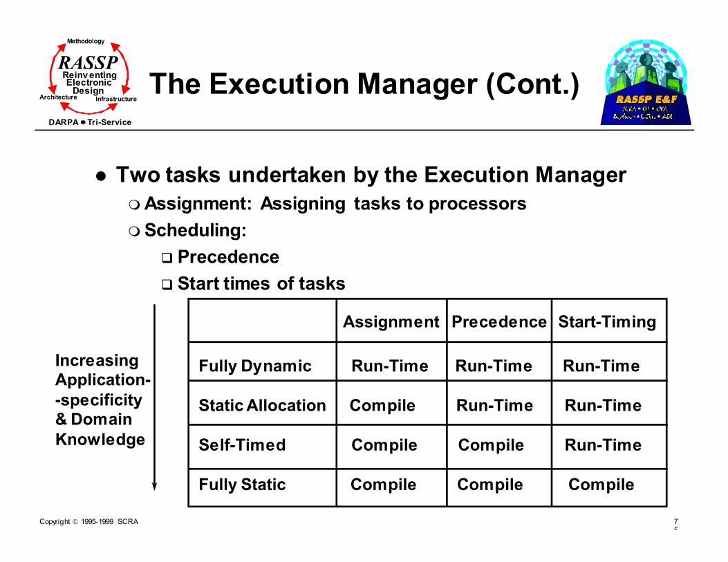
The Execution Manager (Cont.)
� Two tasks undertaken by the Execution Manager
� Assignment: Assigning tasks to processors
� Scheduling:
� Precedence
� Start times of tasks
Assignment Precedence Start-Timing
Fully Dynamic Run-Time Run-Time Run-Time
Static Allocation Compile Run-Time Run-Time
Self-Timed Compile Compile Run-Time
Fully Static Compile Compile Compile
IncreasingApplication-
-specificity& Domain
Knowledge

Copyright 1995-1999 SCRA 76
Methodology
Reinv entingElectronic
DesignArchitecture Infrastructure
DARPA Tri-Service
RASSP
Module Outline
� Introduction
� Requirements Capture
� Fixed-point Design - A RASSP Approach
� Simulation-based Algorithm/Functional Design
� Network-level DSP
� Link-level DSP
� Signal Processing Simulators
� PGM/PGSE
� RASSP Software Generation
� Summary
Copyright 1995-1999 SCRA 77
Methodology
Reinv entingElectronic
DesignArchitecture Infrastructure
DARPA Tri-Service
RASSP
Block Oriented Simulators
� Block-oriented simulators
� Matlab/Simulink
� Mathematica
� Khoros
� Ptolemy/Blossim
� BOSS/SPW
� COSSAP
Primarily BLOCK-ORIENTED simulators capable ofTIME and FREQUENCY domain operations

Copyright 1995-1999 SCRA 78
Methodology
Reinv entingElectronic
DesignArchitecture Infrastructure
DARPA Tri-Service
RASSP
Khoros 2.0
� Khoros is a complete data exploration and software development environment
� Advantages
� Reduces time to solve complex problems
� Provides free sharing of code modules
� Promotes portability
� Primary emphasis
� Software development
� Data visualization
� KHOROS software is divided into several toolboxes
� Toolboxes are organized by function and common objective
Copyright 1995-1999 SCRA 79
Methodology
Reinv entingElectronic
DesignArchitecture Infrastructure
DARPA Tri-Service
RASSP
Software Organization
� Software organization is based on toolbox and software objects
� Craftsman: toolbox management tool
� Composer: software object editor
� Guise: GUI design tool
� Craftsman, Composer and Guise are stand-alone tools
� Cantata is the visual programming language environment
� Complete software development environment
� Data visualization tool
� Algorithm layout tool
Copyright 1995-1999 SCRA 80
Methodology
Reinv entingElectronic
DesignArchitecture Infrastructure
DARPA Tri-Service
RASSP
Flexibility
� Easily configurable to include desired toolboxes and programs
� Simple to add new toolboxes and programs to system
� Use of code generators integrated into Composer
� Composer writes interface code for new programs to reduce programming time
� I/O structure, library includes etc.
� Data processing “operations” based on multi-dimensional polymorphic data model
� Same operator (i.e., FFT) works on 1D, 2D, 3D,... signals

Copyright 1995-1999 SCRA 81
Methodology
Reinv entingElectronic
DesignArchitecture Infrastructure
DARPA Tri-Service
RASSP
Flexibility (Cont.)
� KHOROS 2 programs operate on data independent of storage format
� Example
� Can add 256x300 color Sun raster image with 512x512 VIFF-formatted image without any conversion
� KHOROS 2 can handle large data sets
� Example
� Can take FFT of 2K x 2K x 2K float volume

Copyright 1995-1999 SCRA 82
Methodology
Reinv entingElectronic
DesignArchitecture Infrastructure
DARPA Tri-Service
RASSP
KHOROS Availability
� Free access to KHOROS system
� Not public domain, licensing is done through Khoros Research Inc.
� Available via FTP
� USA ftp.khoros.unm.edu /pub/khoros/khoros2.0
� USA ftp.sdsc.edu /pub/other/khoros/khoros-2
� Germany ftp.uni-koeln.de /graph/khoros2.0
� Web site home page
� http://www.khoros.unm.edu
Copyright 1995-1999 SCRA 83
Methodology
Reinv entingElectronic
DesignArchitecture Infrastructure
DARPA Tri-Service
RASSP
BLOSIM/Ptolemy
� Precursor to Ptolemy (http://ptolemy.eecs.berkeley.edu)
� User writes code for functional blocks, BLOSIM allows blocks to be interconnected and executed as ONE EXECUTABLE in C
� Equivalent to writing a special-purpose simulation for an application, but standard interface allows blocks to be reusable. Allows multiple sampling rates
� Ptolemy adds C++ and links to execution on parallel processors, adds model libraries, and adds a few additional domains
� Essentially a multi-level simulation model described earlier
� Attractive features - Matlab blocks can be included

Copyright 1995-1999 SCRA 84
Methodology
Reinv entingElectronic
DesignArchitecture Infrastructure
DARPA Tri-Service
RASSP
Program Structure in BLOSIM
FIFO Buffer Management
BLOSIM Kernel
User Topology Definition
User BlockRoutines
Blocks communicate through standardized interfaces
[Messerschmitt84]© IEEE 1984

Copyright 1995-1999 SCRA 85
Methodology
Reinv entingElectronic
DesignArchitecture Infrastructure
DARPA Tri-Service
RASSP BOSS/SPWSoftware Structure
Display Screen
Display Manager
Post Processor Block Diagram
Database Code GeneratorSignals
SimulationManager
[BOSS86]
© IEEE 1986

Copyright 1995-1999 SCRA 86
Methodology
Reinv entingElectronic
DesignArchitecture Infrastructure
DARPA Tri-Service
RASSP
Module Outline
� Introduction
� Requirements Capture
� Fixed-Point Design - A RASSP Approach
� Simulation-Based Algorithm/Functional Design
� Network-Level DSP
� Link-Level DSP
� Signal Processing Simulators
� PGM/PGSE
� RASSP Software Generation
� Summary

Copyright 1995-1999 SCRA 87
Methodology
Reinv entingElectronic
DesignArchitecture Infrastructure
DARPA Tri-Service
RASSP
Section Outline
� PGM/PGSE
� PGM/PGSE overview
� Application development in PGM
� Issues in the use of PGM

Copyright 1995-1999 SCRA 88
Methodology
Reinv entingElectronic
DesignArchitecture Infrastructure
DARPA Tri-Service
RASSP Processing Graph Method,PGM
� The PGM allows to develop signal processing applications without any knowledge of the underlying machine architecture
� PGM achieves this goal by providing
� A high level specification
� A graph oriented language
� Tools for translating the graphs into load modules for target machines
� And a run-time support environment which expands the graph instances

Copyright 1995-1999 SCRA 89
Methodology
Reinv entingElectronic
DesignArchitecture Infrastructure
DARPA Tri-Service
RASSP
PGM Fundamentals
� PGM is based on a modified “data flow” methodology
� It differs from the classical data flow in the following
� The input queue threshold can be set more than 1
� An offset can be specified to skip a certain number of input data from the queue before reading data
� The number of elements to read into a node can be specified
� The number of elements to consume from input queues can be specified
� PGM is Data Flow only down to the level of scheduling nodes for execution

Copyright 1995-1999 SCRA 90
Methodology
Reinv entingElectronic
DesignArchitecture Infrastructure
DARPA Tri-Service
RASSP
PGM and DSP
� PGM is to be used to build up signal processing applications
� The signal processing application is defined as a set of graphs and command programs
� The graphs are analogous to flow diagrams used to summarize signal processing flow
� The command programs define the graphs interaction among themselves and the outside world
� The result is a set of graphs and command programs that are translated into load modules which are subsequently executed under the PGM runtime environment
Copyright 1995-1999 SCRA 91
Methodology
Reinv entingElectronic
DesignArchitecture Infrastructure
DARPA Tri-Service
RASSP
The Graph
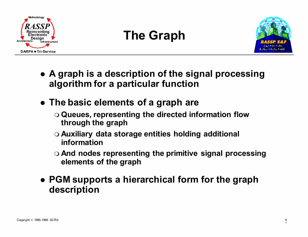
� A graph is a description of the signal processing algorithm for a particular function
� The basic elements of a graph are
� Queues, representing the directed information flow through the graph
� Auxiliary data storage entities holding additional information
� And nodes representing the primitive signal processing elements of the graph
� PGM supports a hierarchical form for the graph description

Copyright 1995-1999 SCRA 92
Methodology
Reinv entingElectronic
DesignArchitecture Infrastructure
DARPA Tri-Service
RASSP
The Queues
� Queues provide the primary data storage and transfer medium for the graph
� The queues are implemented as expandable FIFO
� There are two kinds of queues in PGM
� Data queues, used for passing data between two nodes
� Trigger queue, used for passing channel synchronization signals
� Trigger queues can force a synchronization of an otherwise asynchronous, data driven sequence of operations

Copyright 1995-1999 SCRA 93
Methodology
Reinv entingElectronic
DesignArchitecture Infrastructure
DARPA Tri-Service
RASSP
The Auxiliary Data Storage
� The auxiliary data storage entities are used to hold additional information which would be inconvenient to send using queues
� They are different from queues in that they hold a single datum of the declared mode at a time
� PGM has two auxiliary data storage entities� Graph Variables(GV)
� Internal graph variables, defined within a graph definition with local scope
� A dynamic graph variable, defined within a command program and its scope is all graphs and other command programs to which the command program passes its identifiers
� And Graph Instantiation Parameters(GIP), a start time constant passed at instantiation or or defined within the graph definition

Copyright 1995-1999 SCRA 94
Methodology
Reinv entingElectronic
DesignArchitecture Infrastructure
DARPA Tri-Service
RASSP
The Node
� The node is the basic signal processing entity in PGM
� It is executed when its scheduling criteria have been met
� There are three scheduling criteria
� All input queues must meet or exceed their thresholds
� Machine resources must be available
� Downstream queues must have enough space
� A Node is made up of a
� Primitive
� Port(s)
� And a Primitive Interface Procedure (PIP)

Copyright 1995-1999 SCRA 95
Methodology
Reinv entingElectronic
DesignArchitecture Infrastructure
DARPA Tri-Service
RASSP
The Primitive
� The primitive is the signal processing entity within the node
� It takes input values passed to it by PIP and calculates the output values which it passes back to PIP for appropriate action
� EMSP Common Operational Support Software, ECOS, primitive specification contains information on each primitive that is available to the PGM programmer

Copyright 1995-1999 SCRA 96
Methodology
Reinv entingElectronic
DesignArchitecture Infrastructure
DARPA Tri-Service
RASSP
Ports
� The port is a logical concept defined as the point at which data enter or leave the node
� The classification of ports depends on whether the data are
� Input or output from the node
� From or to queue or auxiliary data storage entity, or
� Used by the primitive alone or by the PIP
� A node must have
� a port attached to an input queue to allow for a node scheduling criterion
� An output port from which more than one datum of the declared mode must be to a queue

Copyright 1995-1999 SCRA 97
Methodology
Reinv entingElectronic
DesignArchitecture Infrastructure
DARPA Tri-Service
RASSP
Primitive Interface Procedure
� The Primitive Interface Procedure (PIP) provides the primitive with appropriate values from the node’s various ports
� The PIP allows for data transfer into and out of the primitive by providing
� A logical connection between the primitives input and output and the input and output queues
� Removal and generation of trigger queue pulses
� Introduction and transmission of graph variable to or from the primitive
� Transmission of constants defined by start time expressions to the primitive
� Calculation of variable Node Execution Parameters (NEPs)

Copyright 1995-1999 SCRA 98
Methodology
Reinv entingElectronic
DesignArchitecture Infrastructure
DARPA Tri-Service
RASSP
Subgraphs
� Subgraphs allow hierarchical structures to be contained within graph definitions
� A subgraph acts like a macro definition in that a subgraph is replaced during the graph instantiation is replaced by the nodes and queues of which the subgraph is composed
� A subgraph may be used several times in the definition of a graph in a manner similar to the way a primitive may be used in several different nodes in a graph

Copyright 1995-1999 SCRA 99
Methodology
Reinv entingElectronic
DesignArchitecture Infrastructure
DARPA Tri-Service
RASSP
Merge
� Merge allows for data dependent data processing
� Merge has several input queues, one being a control queue
� The control queue contains information that tells the merge which one of several input queues is to be read, and then places data to a single output queue
� Control queues are mode integer, they have an implied� Threshold
� Read
� Consume
� And offset, zero

Copyright 1995-1999 SCRA 10
Methodology
Reinv entingElectronic
DesignArchitecture Infrastructure
DARPA Tri-Service
RASSP
Command Program
� Command programs are application dependent and control graph execution and interaction
� Command programs are to be used for control rather than signal processing
� They are written by the application programmer, using a High Order Language (HOL) together with a set of procedure calls defined in the PGM specification
� The HOL provides control structures within which the SPGN procedure calls are embedded
� In addition, communication between the command program and the outside world is supported by the HOL and the underlying operating systems
Copyright 1995-1999 SCRA 10
Methodology
Reinv entingElectronic
DesignArchitecture Infrastructure
DARPA Tri-Service
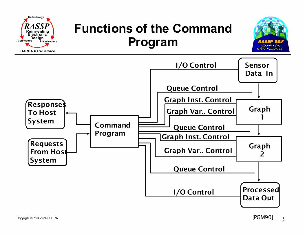
RASSP Functions of the Command Program
ResponsesTo Host System
Requests From HostSystem
Command Program
SensorData In
Graph 1
Graph 2
ProcessedData Out
I/O Control
Queue Control
Graph Inst. Control
Graph Var.. Control
I/O Control
Queue Control
Graph Inst. Control
Queue Control
Graph Var.. Control
[PGM90]

Copyright 1995-1999 SCRA 10
Methodology
Reinv entingElectronic
DesignArchitecture Infrastructure
DARPA Tri-Service
RASSP Functions of the Command Program (Cont.)
� The command program has the capability of
� Defining a queue and and its connections (Queue Control). This capability is important because the graph is defined as having no external queues
� Defining the connection of such a queue to an I/O procedure starting or stopping the procedure (I/O Control)
� Interacting with a graph (Graph Instance Control) by starting, stopping, or reinitializing the graph,
� Or by changing the values of graph variables passed to the graph (Graph Variable Control)
Copyright 1995-1999 SCRA 10
Methodology
Reinv entingElectronic
DesignArchitecture Infrastructure
DARPA Tri-Service
RASSP
I/O Procedures
� I/O procedures are implementation and application specific processes that provide the capability for
� Passing signal input data between external devices and graphs and command programs
� Passing processed output data between graphs and command programs and external devices
� An input I/O procedure takes data from one or more external devices, processes it, and outputs it to one or more dynamic queues
� An output I/O procedure takes data from one or more dynamic queues, processes and outputs it to one or more external devices
Copyright 1995-1999 SCRA 10
Methodology
Reinv entingElectronic
DesignArchitecture Infrastructure
DARPA Tri-Service
RASSP
PGM Runtime Environment
� The command program accomplishes its functions by making calls to the PGM runtime environment
� In addition to providing system calls for the command program, the runtime environment takes care of
� Scheduling the signal processing tasks for execution
� Managing and allocating processing resources
� Performing memory management services

Copyright 1995-1999 SCRA 10
Methodology
Reinv entingElectronic
DesignArchitecture Infrastructure
DARPA Tri-Service
RASSP
PGM Overview Summary
� PGM is based on a modified data flow methodology
� A PGM application consists of graphs and command programs
� PGM graph is composed of
� Node (s)
� Queue (s)
� Sub-graphs
� PGM command programs perform
� Queue Control
� I/O control
� Graph Instance Control
� Graph Variable Control

Copyright 1995-1999 SCRA 10
Methodology
Reinv entingElectronic
DesignArchitecture Infrastructure
DARPA Tri-Service
RASSP Application Development in PGM
� The starting point for developing a PGM graph is a signal processing flow diagram
� Consider the simple example band definition filtering on one beam of acoustic time-series data
� The frequency band is defined by the bandshift and subsequent low pass filtering. The sampling rate is to be reduced by a factor of 8 (8:1 decimation)
Beam_in Band_outBandshift Filte
r
Signal Processing Flow Diagram for Band Definition Filtering[PGM90]

Copyright 1995-1999 SCRA 10
Methodology
Reinv entingElectronic
DesignArchitecture Infrastructure
DARPA Tri-Service
RASSP Application Development in PGM (Cont.)
� Each of the distinct operations in the previous block diagram corresponds to a node of a the PGM graph
� The data passed between these nodes corresponds to the data queue
� To change the block diagram to a PGM graph, the following steps are required
� Lay out the nodes and queues
� Select a descriptive name for each node
� Select a name for each queue
� Find the appropriate primitives to perform the required signal processing functions in the block diagram using the ECOS primitive specification
Copyright 1995-1999 SCRA 10
Methodology
Reinv entingElectronic
DesignArchitecture Infrastructure
DARPA Tri-Service
RASSP Application Development in PGM (Cont.)
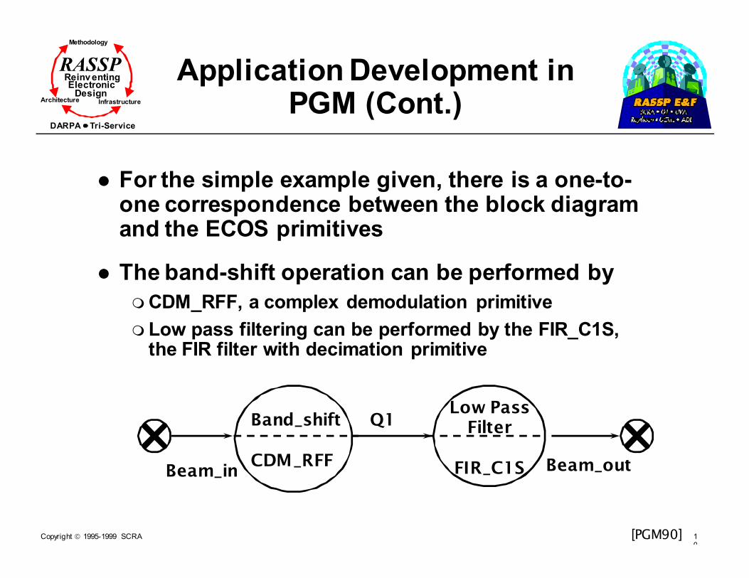
� For the simple example given, there is a one-to-one correspondence between the block diagram and the ECOS primitives
� The band-shift operation can be performed by
� CDM_RFF, a complex demodulation primitive
� Low pass filtering can be performed by the FIR_C1S, the FIR filter with decimation primitive
Band_shift
CDM_RFF
Low PassFilter
FIR_C1SBeam_in Beam_out
Q1
[PGM90]

Copyright 1995-1999 SCRA 10
Methodology
Reinv entingElectronic
DesignArchitecture Infrastructure
DARPA Tri-Service
RASSP Application Development in PGM (Cont.)
� Each primitive in the ECOS has a data sheet that specifies
� Description
� Specifies the functionality of the primitive
� The method of implementation
� Errors inherent in the algorithm
� Reference for the algorithm
� Pseudo Code
� Parameter List, a listing of all input and output parameters with descriptions
� A list of constraints for the primitive
� Performance Features
� Performance Guidelines for Exception Handling
� Execution time formulas
Copyright 1995-1999 SCRA 11
Methodology
Reinv entingElectronic
DesignArchitecture Infrastructure
DARPA Tri-Service
RASSP Application Development in PGM (Cont.)
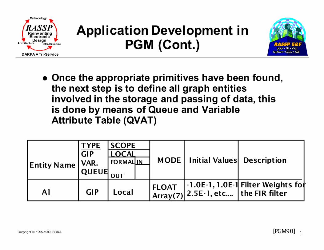
� Once the appropriate primitives have been found, the next step is to define all graph entities involved in the storage and passing of data, this is done by means of Queue and Variable Attribute Table (QVAT)
Entity Name
TYPEGIPVAR.QUEUE
SCOPELOCALFORMAL IN
OUT
MODE Initial Values Description
A1 GIP LocalFLOATArray(7)
-1.0E-1, 1.0E-12.5E-1, etc....
Filter Weights forthe FIR filter
[PGM90]

Copyright 1995-1999 SCRA 11
Methodology
Reinv entingElectronic
DesignArchitecture Infrastructure
DARPA Tri-Service
RASSP Application Development in PGM (Cont.)
� The next step in the process is to define all the connections among the different nodes of the graph: this is done by means of node attribute table
� For each node in a graph, there should be a corresponding node attribute table
Node NameFIR_NODE
Primitive NameFIR_C1S
INDEXING DescriptionFinite Impulse Response Filter
PIP_INs Threshold Read V| Offset V| Consume Description
PRIM_INs Threshold V|Read V| Offset V| Consume Description
Q1 137 137 0 128 Input Data
PRIM_OUTs V| Valve Output Data
PIP_OUTs V | Pulse/Produce
Description
Description
[PGM90]

Copyright 1995-1999 SCRA 11
Methodology
Reinv entingElectronic
DesignArchitecture Infrastructure
DARPA Tri-Service
RASSP Application Development in PGM (Cont.)
� Functions of command program fall into five categories� Command program control
� Input/Output control
� Graph instance control
� Queue control
� Graph variable control
� A combination of HOL and command program, SPGN, procedures are used to� Define the control flow structure
� I/O to an “operator” or controlling computer
� Command program, SPGN is used to coordinate the interactions� Between command programs and graph instances
� Between two command programs

Copyright 1995-1999 SCRA 11
Methodology
Reinv entingElectronic
DesignArchitecture Infrastructure
DARPA Tri-Service
RASSP Application Development in PGM (Cont.)
� Command program control
� One command program is designated as the initial command program and is started at startup
� All other command programs are created (spawned) by this initial command program
� There are two procedures for command program control
� %SPAWN, used to start another command program and to pass arguments to it
�The procedure returns the identifier Command_Program_id
� %ABORT, used to abort a command program
�A command program can only abort itself or any other command programs that it had spawned.
Copyright 1995-1999 SCRA 11
Methodology
Reinv entingElectronic
DesignArchitecture Infrastructure
DARPA Tri-Service
RASSP Application Development in PGM (Cont.)
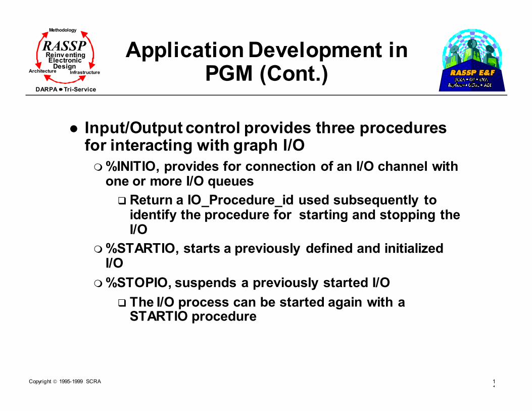
� Input/Output control provides three procedures for interacting with graph I/O
� %INITIO, provides for connection of an I/O channel with one or more I/O queues
� Return a IO_Procedure_id used subsequently to identify the procedure for starting and stopping the I/O
� %STARTIO, starts a previously defined and initialized I/O
� %STOPIO, suspends a previously started I/O
� The I/O process can be started again with a STARTIO procedure

Copyright 1995-1999 SCRA 11
Methodology
Reinv entingElectronic
DesignArchitecture Infrastructure
DARPA Tri-Service
RASSP Application Development in PGM (Cont.)
� Graph instance control is responsible for transforming the applications graph into a static description of the signal processing graph
� In order for a graph to be executed, graph realization must be used to
� Create a particular graph instance with particular
� Queues
� Nodes
� Graph variables
� It is possible to have many different graph instances that started from the same graph realization active at the same time
Copyright 1995-1999 SCRA 11
Methodology
Reinv entingElectronic
DesignArchitecture Infrastructure
DARPA Tri-Service
RASSP Application Development in PGM (Cont.)
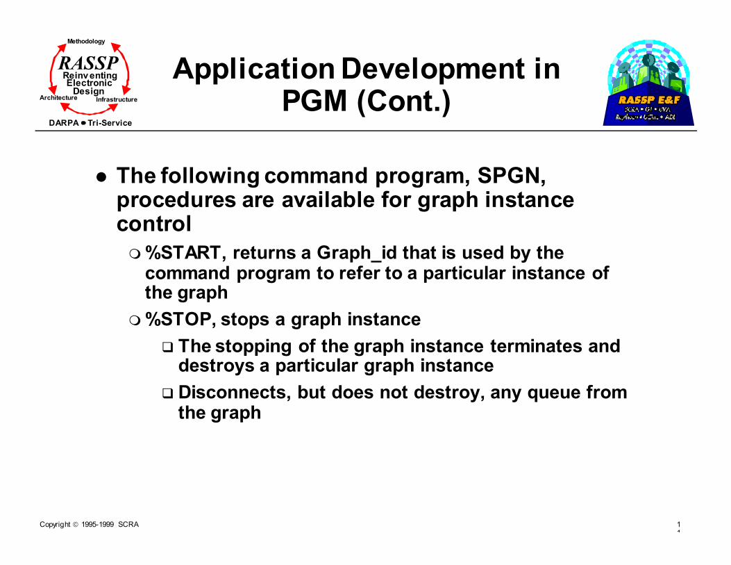
� The following command program, SPGN, procedures are available for graph instance control
� %START, returns a Graph_id that is used by the command program to refer to a particular instance of the graph
� %STOP, stops a graph instance
� The stopping of the graph instance terminates and destroys a particular graph instance
� Disconnects, but does not destroy, any queue from the graph

Copyright 1995-1999 SCRA 11
Methodology
Reinv entingElectronic
DesignArchitecture Infrastructure
DARPA Tri-Service
RASSP Application Development in PGM (Cont.)
� There are eleven procedures available under command program, SPGN, for manipulating queues
� %CreateQ, causes a queue to be created dynamically
� %DestroyQ, destroys a dynamically created queue
� %INITQ, Initializes a dynamically created queue
� %FLUSHQ, removes all data elements from a queue
� %CONNECTQ, connects the command program to head or tail of a previously created queue
� %DISCONNECTQ, releases the queue from the command program
� %ADDDATA, adds data to a queue behind the data already in the queue
� %READQ, reads a number of data elements from a queue to a command program, when enough data present.
� %WAIT, waits for a specified event to occur
� %UNLINK, disconnect dynamically created queue from a graph
� %LINK, allows dynamically created queues to connect to graph I/O ports

Copyright 1995-1999 SCRA 11
Methodology
Reinv entingElectronic
DesignArchitecture Infrastructure
DARPA Tri-Service
RASSP Application Development in PGM (Cont.)
� PGM provides four procedures for command programs to interact with graph variables
� %CREATEGV
� Dynamically creates a graph variable and returns an identifier which it can be referenced
� %DESTROYGV
� Destroys a a previously dynamically created graph variable
� %READGV
� Enables the command program to read a data element or group of array elements from a graph variable
� %WRITEGV
� Used by the command program to place data onto a graph variable
Copyright 1995-1999 SCRA 11
Methodology
Reinv entingElectronic
DesignArchitecture Infrastructure
DARPA Tri-Service
RASSP
Application of PGM in RASSP
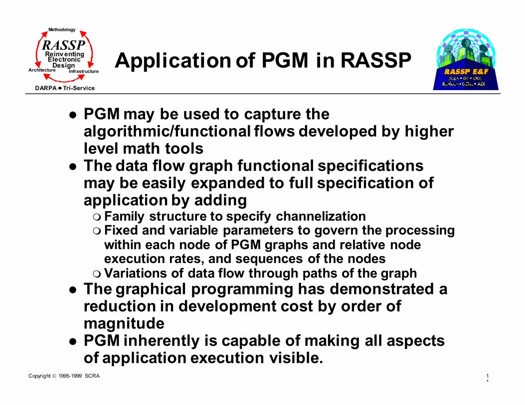
� PGM may be used to capture the algorithmic/functional flows developed by higher level math tools
� The data flow graph functional specifications may be easily expanded to full specification of application by adding� Family structure to specify channelization� Fixed and variable parameters to govern the processing
within each node of PGM graphs and relative node execution rates, and sequences of the nodes
� Variations of data flow through paths of the graph
� The graphical programming has demonstrated a reduction in development cost by order of magnitude
� PGM inherently is capable of making all aspects of application execution visible.

Copyright 1995-1999 SCRA 12
Methodology
Reinv entingElectronic
DesignArchitecture Infrastructure
DARPA Tri-Service
RASSP
Issues in the use of PGM
� There are some processes that do not lend themselves to data flow specification. How will PGM accommodate these?
� The overhead associated with scheduling and data flow, communication, may be intolerable for some high data rate applications?
� The only available run time support for PGM at this time is the AN/UYS-2 which provides hardware support that is not portable to RASSP Model Year Architectures (MYA). The development cost of such run time systems would rise the application development cost considerably
Copyright 1995-1999 SCRA 12
Methodology
Reinv entingElectronic
DesignArchitecture Infrastructure
DARPA Tri-Service
RASSP Issues in the use of PGM (Cont.)
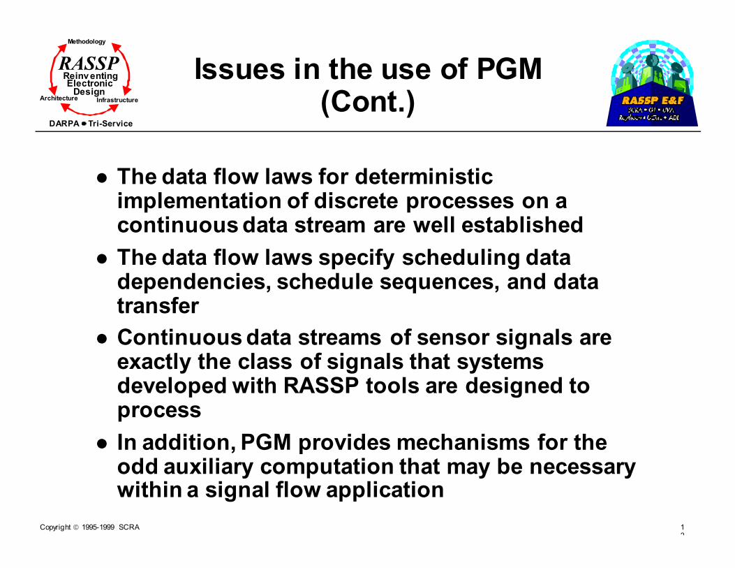
� The data flow laws for deterministic implementation of discrete processes on a continuous data stream are well established
� The data flow laws specify scheduling data dependencies, schedule sequences, and data transfer
� Continuous data streams of sensor signals are exactly the class of signals that systems developed with RASSP tools are designed to process
� In addition, PGM provides mechanisms for the odd auxiliary computation that may be necessary within a signal flow application
Copyright 1995-1999 SCRA 12
Methodology
Reinv entingElectronic
DesignArchitecture Infrastructure
DARPA Tri-Service
RASSP Issues in the use of PGM (Cont.)
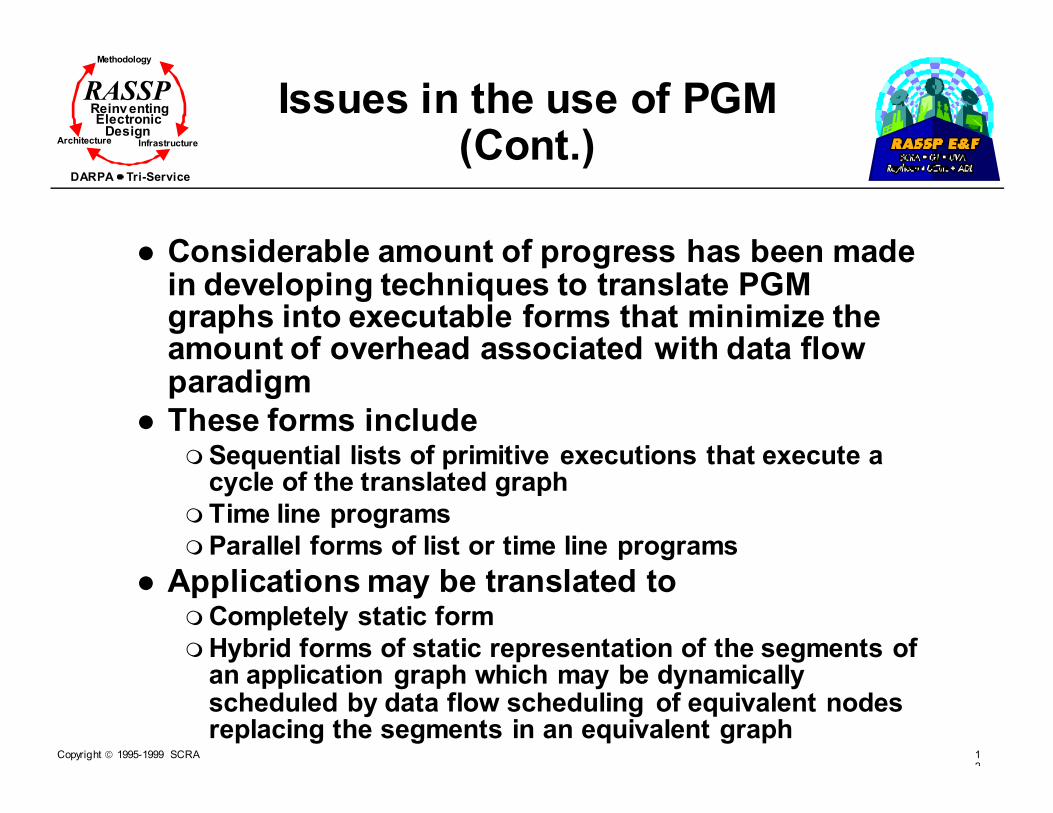
� Considerable amount of progress has been made in developing techniques to translate PGM graphs into executable forms that minimize the amount of overhead associated with data flow paradigm
� These forms include� Sequential lists of primitive executions that execute a
cycle of the translated graph
� Time line programs
� Parallel forms of list or time line programs
� Applications may be translated to� Completely static form
� Hybrid forms of static representation of the segments of an application graph which may be dynamically scheduled by data flow scheduling of equivalent nodes replacing the segments in an equivalent graph
Copyright 1995-1999 SCRA 12
Methodology
Reinv entingElectronic
DesignArchitecture Infrastructure
DARPA Tri-Service
RASSP
Module Outline
� Introduction
� Requirements Capture
� Fixed-Point Design - A RASSP Approach
� Simulation-Based Algorithm/Functional Design
� Network-Level DSP
� Link-Level DSP
� Signal Processing Simulators
� PGM/PGSE
� RASSP Software Generation
� Summary
Copyright 1995-1999 SCRA 12
Methodology
Reinv entingElectronic
DesignArchitecture Infrastructure
DARPA Tri-Service
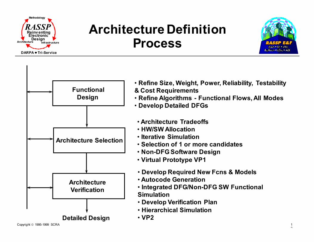
RASSP Architecture Definition Process
Functional
Design
Architecture Selection
Architecture
Verification
Detailed Design
• Refine Size, Weight, Power, Reliability, Testability
& Cost Requirements
• Refine Algorithms - Functional Flows, All Modes
• Develop Detailed DFGs
• Architecture Tradeoffs
• HW/SW Allocation
• Iterative Simulation
• Selection of 1 or more candidates
• Non-DFG Software Design
• Virtual Prototype VP1
• Develop Required New Fcns & Models
• Autocode Generation
• Integrated DFG/Non-DFG SW Functional
Simulation
• Develop Verification Plan
• Hierarchical Simulation
• VP2

Copyright 1995-1999 SCRA 12
Methodology
Reinv entingElectronic
DesignArchitecture Infrastructure
DARPA Tri-Service
RASSP PGM Utilization in the Design Process
[LMC-ARCH]
•PGM Tools
•PGSE
•NetSyn
•Autocode Tools
•NetSyn
AlgorithmSpecification
PGM DFGSimulation
ArchitectureTradeoffs
AutocodeGeneration
PerformanceResimulation
• User must be familiar with PGM
• Data flow control is considered
at outset as part of graph
• Used to verify PGM graph with
respect to functional spec.
• Driven from PGM graph and
PGSE simulation results
• Driven from architecture and
DFG mapping to processors
• Provides verification of
autocode results with original
graph

Copyright 1995-1999 SCRA 12
Methodology
Reinv entingElectronic
DesignArchitecture Infrastructure
DARPA Tri-Service
RASSP
Functional Design
[LMC-ARCH]
Architecture
Sizing
Initiate
Primitive
DevelopmentSelection
Criteria
Definition
Flow Graph
Generation
DFG
Simulation
Develop
Command
Program
Functional
Simulation
•Algorithm implementation analysis (ops/s, mem, I/O)•Algorithm simulation/ optimization
• Develop functional models
• ‘ilitities and cost assessment
• Refine processing flows (all modes)
To architecture selection
• Transform processing flows to detailed DFGs
• Translate control reqmts.
to control flow graphs
• Validate DFG functionality for all
modes
• Prioritize requirements• Define selection criteria
• CASE tools• Autocode
generation
• Joint CFG/DFG simulation
• Validate functional
interaction

Copyright 1995-1999 SCRA 12
Methodology
Reinv entingElectronic
DesignArchitecture Infrastructure
DARPA Tri-Service
RASSP Algorithm DesignProcess in RASSP
� Algorithm flows specified in SPW, or any other higher level math tool, form are captured as PGM graphs
� The initial graph is functional only, expressing the mathematical operations in the algorithm flow as nodes or subgraphs and the data flow as queues
� Recording queue contents during execution will provide intermediate result for comparison from those of the SPW representation
� This functional graph is then expanded into a full application specification
Copyright 1995-1999 SCRA 12
Methodology
Reinv entingElectronic
DesignArchitecture Infrastructure
DARPA Tri-Service
RASSP Application Development Process in RASSP
� Topology is expanded to represent
� All possible data paths
� Controls are specified for all operating modes
� Sets or ranges of values for all variables are specified
� Graphical specification and execution tools are used to produce a full PGM specification of the applications
� Primitive support is target independent, allowing for the execution of domain primitives on general purpose hardware running the graph execution tool
� Provisional primitives may be added through library population for SPW functions for which no library support exist

Copyright 1995-1999 SCRA 12
Methodology
Reinv entingElectronic
DesignArchitecture Infrastructure
DARPA Tri-Service
RASSP
RASSP PGM Functionality
AlgorithmsFlow
External ReqSpecifications
Partition PID
Partition Specification
PartitionGraph
Partitioned SWGraph
GraphRealization
Equivalent Application Graph
AllocatedGraph
Application Validation Graph
HW FunctionalSpecifications
I/O ProcedureSpecifications
I/O Requirements
ExternalCommands
State Diagrams
Command ProgSpecifications
Command ProgSpecifications
[MMC/LMC 94]
Copyright 1995-1999 SCRA 13
Methodology
Reinv entingElectronic
DesignArchitecture Infrastructure
DARPA Tri-Service
RASSP Application Development Process in RASSP: System
Definition
� Algorithm flows � Are block diagrams depicting the high-level
computations associated with an application, e.g. SPW, MATLAB
� I/O requirements � Identify the amount of throughput the application will
have to handle, modes of data, and the source(s) of the data
� External commands� Are formal definitions of all commands allowable to the
operator
� State transition diagrams � Depict the major modes of system operation, and the
state changes between them. They, along with the external commands, are the basis for the command program specifications

Copyright 1995-1999 SCRA 13
Methodology
Reinv entingElectronic
DesignArchitecture Infrastructure
DARPA Tri-Service
RASSP Application Development Process in RASSP:
Requirement Refinement
� Executable Requirements Specification
� A PGM graph is composed of domain primitives, domain subgraphs, provisional primitives or subgraphs or any entity which can specify the workings of an algorithm
� Command Program Specifications
� Derived from the state transition diagrams and the external definitions defined in the previous phase

Copyright 1995-1999 SCRA 13
Methodology
Reinv entingElectronic
DesignArchitecture Infrastructure
DARPA Tri-Service
RASSP Architecture Selection Process
[LMC-ARCH]
FunctionalDesign
ArchitectureSelection
ArchitectureVerification
Detailed Design
• Refine size, weight, power, reliability,
testability and cost requirements
• Refine algorithms - Functional flows,
all modes
• Develop detailed DFGs
• Architecture tradeoffs• HW/SW allocation
• Iterative simulation
• Selection of 1 or more candidates
• Non-DFG software design
• Virtual prototype VP1
• Develop required new fcts and models• Autocode generation
• Integrated DFG / Non-DFG SW functional
simulation
• Develop verification plan
• Hierarchical simulation• Virtual prototype VP2
Fe
ed
ba
ck
Pa
th

Copyright 1995-1999 SCRA 13
Methodology
Reinv entingElectronic
DesignArchitecture Infrastructure
DARPA Tri-Service
RASSP
Flow Graph Generation
ProcessingFlows
Demod.
BP Filter
PSD
Freq. Det.
Pwr Det.
S&H
Edge Det.
FFT
Corr. Mix
Peak Pick
Lag DomainBeamform
DomainPrimitive
Graph
Demod
FIR1
FIR2
FFT REP8
PSD Det_PW
REP
Det_Freq.
Sum
Lag_Dom
S&H
MAG
EAVE
DIFF
FFT8
Covar_MA
Covar_SUB
Peak_PK
[LMC-Meth]
PGMTools
Copyright 1995-1999 SCRA 13
Methodology
Reinv entingElectronic
DesignArchitecture Infrastructure
DARPA Tri-Service
RASSP Application Development Process in RASSP: Architecture
Selection/Verification
� Domain Primitive Graph
� Is the executable requirement specification refined to contain only domain level primitives and subgraphs
� Becomes the functional baseline graph for the application once it has been validated with the test vectors developed for the executable refinement specification
� Allocated Graph
� Produced by assigning each domain primitive node or subgraph of the domain primitive graph onto hardware or software components

Copyright 1995-1999 SCRA 13
Methodology
Reinv entingElectronic
DesignArchitecture Infrastructure
DARPA Tri-Service
RASSP Application Development Process in RASSP: Architecture
Selection/Verification (Cont.)
� Partitioned Graph� Is the state of the domain primitive graph after the
partitioning process
� Is not a separate graph, but merely the domain primitive graph with partitioning information
� Partitioned Software Graph� Is the subset of the partitioned graph which will be used
by the software development team
� May be partitioned separately from the full partitioned graph so that software partition performance may be optimized
� Criteria to be used in determining the optimal scheme are:
� The best processor class for each partition in the graph
� The selection of run-time system to be used based on the characteristics of the application, i.e. static, hybrid, etc

Copyright 1995-1999 SCRA 13
Methodology
Reinv entingElectronic
DesignArchitecture Infrastructure
DARPA Tri-Service
RASSP Application Development Process in RASSP: Architecture
Selection/Verification (Cont.)
� Partition Graph
� Is a stand-alone SPGN graph which represents either a hardware or a software partition
� Corepresentation Validation Graph
� Is a PGM graph in which all partitions identified in the partitioned graph have been replaced with equivalent nodes
� This graph is used to simulate the functionality and performance of the entire application graph on selected candidate architecture
� Partition Specification
� For each partition graph, a partition specification is produced providing an interface to the partition PID which is produced to represent the partition graph

Copyright 1995-1999 SCRA 13
Methodology
Reinv entingElectronic
DesignArchitecture Infrastructure
DARPA Tri-Service
RASSP Application Development Process in RASSP: Target
Software Generation
� Equivalent Application Graph
� Is produced from the partitioned software graph by replacing each software partition with an
equivalent node produced by Multi-processor Primitive Interface Description (MPID) generator
� Graph Realization
� Is the compiled version of the equivalent application graph
� Partition PID
� A partition PID is the source code that represents a partition graph, written in the computational element’s native language
� Load Image
� Is the end product of software development process

Copyright 1995-1999 SCRA 13
Methodology
Reinv entingElectronic
DesignArchitecture Infrastructure
DARPA Tri-Service
RASSP Application Development Process in RASSP: Target
Software Generation
L
o
a
d
I
m
a
g
e
Run Time Utilities
Schedule &Control
Partition Application
Code
Run Time Partitioning
Kernel OS
Compiled
Code
Compiled Partition
Code
Run TimeObject
Code
DSP Libraries
ApplicationGraph
GraphRealizations
Command Program
[MMC/LMC 94]
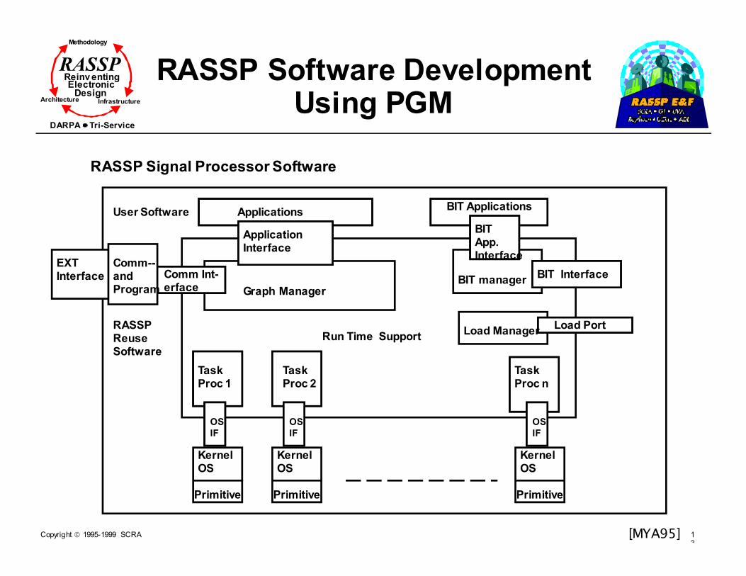
Copyright 1995-1999 SCRA 13
Methodology
Reinv entingElectronic
DesignArchitecture Infrastructure
DARPA Tri-Service
RASSP RASSP Software Development Using PGM
RASSP Signal Processor Software
User Software
RASSP ReuseSoftware
KernelOS
Primitive
KernelOS
Primitive
KernelOS
Primitive
OS
IF
OS
IF
OS
IF
Task Proc 1
Task Proc n
Task Proc 2
Comm--andProgram
EXTInterface Comm Int-
erface Graph Manager
Application Interface
ApplicationsBIT Applications
BIT App.Interface
Run Time Support
BIT managerBIT Interface
Load PortLoad Manager
[MYA95]

Copyright 1995-1999 SCRA 14
Methodology
Reinv entingElectronic
DesignArchitecture Infrastructure
DARPA Tri-Service
RASSP RASSPSoftware Architecture Integration
Operating System
Application
Application Programmer Interface
Command Program(s) Data Flow Graph(s)
PGM Control Interface
PGM Data FlowInterface
Target Proc.MapTarget Proc.Prim Lib.
RealTimePOSIX
Micro/Nanokernel
Baseline Software architecture provides common interface for implementing both control and signal processing aspects of application.
Real TimePOSIX
[MYA95]

Copyright 1995-1999 SCRA 14
Methodology
Reinv entingElectronic
DesignArchitecture Infrastructure
DARPA Tri-Service
RASSP Tools for Architecture Selection and Verification
� NetSyn: (Assignment/Performance Simulation)
� Driven from PGM data flow graph and PGSE output
� Performance simulation for candidate architectures
� Library primitives
� PGSE executables
� Target dependent timing database
� Outputs include reports, architecture, mapping, and graph
[MYA95]
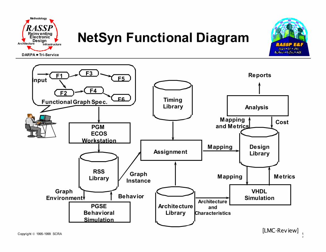
Copyright 1995-1999 SCRA 14
Methodology
Reinv entingElectronic
DesignArchitecture Infrastructure
DARPA Tri-Service
RASSP
NetSyn Functional Diagram
[LMC-Rev iew]
F6
inputF1
F2
F3
F4
F5
Functional Graph Spec. F6
PGM ECOS
Workstation
RSSLibrary
PGSEBehavioral
Simulation
GraphEnvironment Behavior
TimingLibrary
Assignment
GraphInstance
ArchitectureLibrary
Analysis
Mapping DesignLibrary
Mappingand Metrics
Cost
VHDLSimulation
Mapping Metrics
Reports
Architectureand
Characteristics
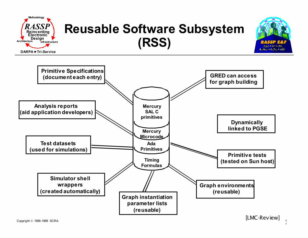
Copyright 1995-1999 SCRA 14
Methodology
Reinv entingElectronic
DesignArchitecture Infrastructure
DARPA Tri-Service
RASSP Reusable Software Subsystem (RSS)
[LMC-Rev iew]
Primitive Specifications(document each entry)
Analysis reports(aid application developers)
Test datasets(used for simulations)
Simulator shellwrappers
(created automatically)Graph instantiation
parameter lists
(reusable)
Graph environments(reusable)
Primitive tests(tested on Sun host)
Dynamically linked to PGSE
GRED can accessfor graph building
MercurySAL C
primitives
MercuryMicrocode
AdaPrimitives
TimingFormulas
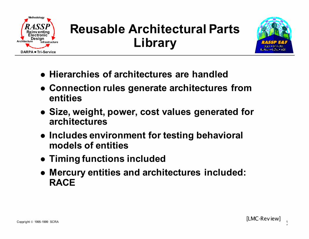
Copyright 1995-1999 SCRA 14
Methodology
Reinv entingElectronic
DesignArchitecture Infrastructure
DARPA Tri-Service
RASSP Reusable Architectural Parts Library
� Hierarchies of architectures are handled
� Connection rules generate architectures from entities
� Size, weight, power, cost values generated for architectures
� Includes environment for testing behavioral models of entities
� Timing functions included
� Mercury entities and architectures included: RACE
[LMC-Rev iew]

Copyright 1995-1999 SCRA 14
Methodology
Reinv entingElectronic
DesignArchitecture Infrastructure
DARPA Tri-Service
RASSP Tools for Architecture Selection and Verification (Cont.)
� Autocode: (Code generation and run-time control)
� Driven from PGM data flow graph, architecture, and mapping
� Library primitives
� Target independent PGSE executables
� Target primitive maps (TPMs) to specific target processors
� Outputs include
� Modified graph
� Timing estimates for graph
� Target code compatible with run time system
[LMC-Rev iew]

Copyright 1995-1999 SCRA 14
Methodology
Reinv entingElectronic
DesignArchitecture Infrastructure
DARPA Tri-Service
RASSP
Autocoding Process
[LMC-Rev iew]
RASSP Library
Domain Primitive DatabaseDomain primitives
Ada Domain primitive
Algorithms
Target primitive maps
Documentation
Test vectors
BIT ApplicationsKernel OS
Target Primitives
Equivalent GraphGeneration and verification
Architecture
Detailed Design
Target-IndependentPartition Autocoding
(Behavior Modeling)
Target Dependent
Partition Autocoding
Equivalent Graph
Autocoding
ApplicationGeneration
• Domain-primitive Application graphs
• Partition node lists
• Configuration file
• Equivalent graph• Performance
estimates
• Partition graph for each partition
• Equivalent graph
• Partition target-independent Ada
procedures
(behavior models)
• Partition target-
dependent ‘C’ programs
• Equivalent graph
data structures• Load Image make
file

Copyright 1995-1999 SCRA 14
Methodology
Reinv entingElectronic
DesignArchitecture Infrastructure
DARPA Tri-Service
RASSP Autocoding Process Inputs and Outputs
� Inputs to the autocoding process
� PGM application graph SPGN file
� Candidate architecture configuration file
� Lists of nodes in processor software partitions
� Lists of nodes in hardware partitions
� Autocoding outputs
� Partition “C” programs for target processors
� Partition and application performance estimates generated
� Run-time system load image for candidate architecture
� Behavior models for hardware or software partition
[LMC-Rev iew]

Copyright 1995-1999 SCRA 14
Methodology
Reinv entingElectronic
DesignArchitecture Infrastructure
DARPA Tri-Service
RASSP
Autocoding Run-Time Support
[LMC-Rev iew]
User Software
RASSP ReuseSoftware
KernelOS
Primit ive
KernelOS
Primit ive
KernelOS
Primit ive
OSIF
OSIF
OSIF
Task Proc 1
Task Proc n
Task Proc 2
Comm-and
Program
EXTInt erface Command
Int erfaceGraph Manager
Applicat ion Int erface
Applicat ionsBIT Applicat ions
BIT App.
Int erface
Run Time Support
BIT managerBIT Int erface
Load PortLoad Manager
Model YearArchitecture
Software
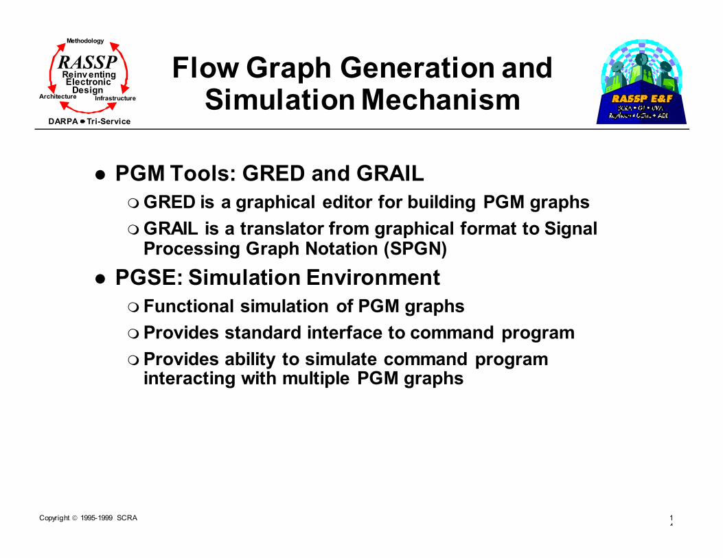
Copyright 1995-1999 SCRA 14
Methodology
Reinv entingElectronic
DesignArchitecture Infrastructure
DARPA Tri-Service
RASSP Flow Graph Generation and Simulation Mechanism
� PGM Tools: GRED and GRAIL
� GRED is a graphical editor for building PGM graphs
� GRAIL is a translator from graphical format to Signal Processing Graph Notation (SPGN)
� PGSE: Simulation Environment
� Functional simulation of PGM graphs
� Provides standard interface to command program
� Provides ability to simulate command program interacting with multiple PGM graphs

Copyright 1995-1999 SCRA 15
Methodology
Reinv entingElectronic
DesignArchitecture Infrastructure
DARPA Tri-Service
RASSP
GEDAE™
� The Graphical Entry Distributed Application Environment closely relates to PGM and its supporting tools.
� The environment is used to
� Graphically construct application graphs
� Distribute the application graph on remote processors

Copyright 1995-1999 SCRA 15
Methodology
Reinv entingElectronic
DesignArchitecture Infrastructure
DARPA Tri-Service
RASSP GEDAE’s Software Architecture
Flow Graph Editor
Distributed Application Shell
Distributed Object System
Network Communication
Work
StationUniProc SIMD
Proc.
MIMD
Proc.
Signal
Proc.
• Software for
interconnecting processing
functions on a
heterogeneous network• Isolate data flow software
from the application-specific
computation
• Facilitates timing analyses
of computation and
communication• Provide object-oriented
programming concept to
heterogeneous network
• Provides processor-
independent
communications
Network

Copyright 1995-1999 SCRA 15
Methodology
Reinv entingElectronic
DesignArchitecture Infrastructure
DARPA Tri-Service
RASSP A Case Study of RASSP Software Development Using GEDAE
� Reduce development/lifecycle cost of DSPs
� Minimize hardware dependence � Enable rapid porting to new hardware
� Maximize software reuse� Minimize rework between algorithm stage and system
implementation
� Enable rapid HW/SW tradeoffs of candidate system architectures prior to implementation� Enable rapid repartitioning and assignment of functionality between
microprocessors
� Minimize rework for system upgrades
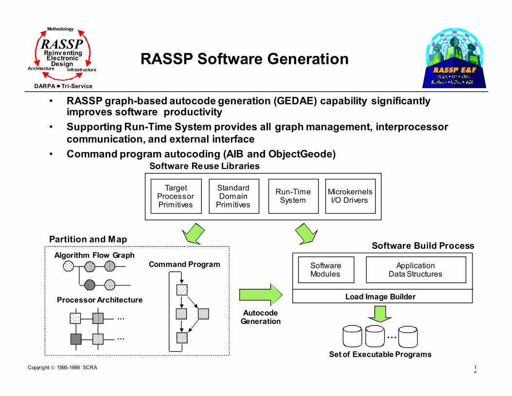
Copyright 1995-1999 SCRA 15
Methodology
Reinv entingElectronic
DesignArchitecture Infrastructure
DARPA Tri-Service
RASSP
RASSP Software Generation
• RASSP graph-based autocode generation (GEDAE) capability significantly improves software productivity
• Supporting Run-Time System provides all graph management, interprocessor
communication, and external interface
• Command program autocoding (AIB and ObjectGeode)
SoftwareModules
ApplicationData Structures
Software Build Process
Command Program
Processor Architecture
Z
Z
Partition and Map
Z
Set of Executable Programs
Algorithm Flow Graph
Load Image Builder
AutocodeGeneration
TargetProcessorPrimitives
StandardDomainPrimitives
Software Reuse Libraries
Run-TimeSystem
MicrokernelsI/O Drivers
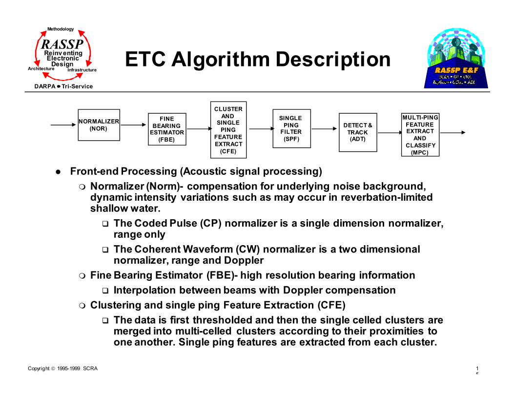
Copyright 1995-1999 SCRA 15
Methodology
Reinv entingElectronic
DesignArchitecture Infrastructure
DARPA Tri-Service
RASSP
ETC Algorithm Description
� Front-end Processing (Acoustic signal processing)
� Normalizer (Norm)- compensation for underlying noise background, dynamic intensity variations such as may occur in reverbation-limited shallow water.
� The Coded Pulse (CP) normalizer is a single dimension normalizer, range only
� The Coherent Waveform (CW) normalizer is a two dimensional normalizer, range and Doppler
� Fine Bearing Estimator (FBE)- high resolution bearing information
� Interpolation between beams with Doppler compensation
� Clustering and single ping Feature Extraction (CFE)
� The data is first thresholded and then the single celled clusters are merged into multi-celled clusters according to their proximities to one another. Single ping features are extracted from each cluster.
CLUSTER
ANDSINGLE
PING
FEATURE
EXTRACT
(CFE)
DETECT &
TRACK(ADT)
MULTI-PING
FEATUREEXTRACT
AND
CLASSIFY
(MPC)
NORMALIZER
(NOR)
FINE
BEARINGESTIMATOR
(FBE)
SINGLE
PINGFILTER
(SPF)

Copyright 1995-1999 SCRA 15
Methodology
Reinv entingElectronic
DesignArchitecture Infrastructure
DARPA Tri-Service
RASSP
ETC Algorithm Description
� Back-end Processing (detection and classification)
� Single Ping Cluster Filtering (SPF)- weed out some of the echo returns from clutter
� Automatic Detection and Tracking (ADT)-automates the detection of potential targets over multiple pings.
� Multi-ping Classifier (MPC)- classifies each track into three possible states, sub, non-sub or pending.
CLUSTER
ANDSINGLE
PING
FEATURE
EXTRACT
(CFE)
DETECT &
TRACK(ADT)
MULTI-PING
FEATUREEXTRACT
AND
CLASSIFY
(MPC)
NORMALIZER
(NOR)
FINE
BEARINGESTIMATOR
(FBE)
SINGLE
PINGFILTER
(SPF)
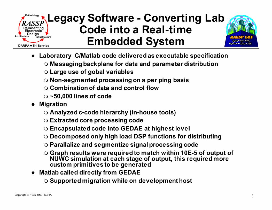
Copyright 1995-1999 SCRA 15
Methodology
Reinv entingElectronic
DesignArchitecture Infrastructure
DARPA Tri-Service
RASSPLegacy Software - Converting Lab
Code into a Real-time Embedded System
� Laboratory C/Matlab code delivered as executable specification
� Messaging backplane for data and parameter distribution
� Large use of gobal variables
� Non-segmented processing on a per ping basis
� Combination of data and control flow
� ~50,000 lines of code
� Migration
� Analyzed c-code hierarchy (in-house tools)
� Extracted core processing code
� Encapsulated code into GEDAE at highest level
� Decomposed only high load DSP functions for distributing
� Parallalize and segmentize signal processing code
� Graph results were required to match within 10E-5 of output of NUWC simulation at each stage of output, this required more custom primitives to be generated
� Matlab called directly from GEDAE
� Supported migration while on development host

Copyright 1995-1999 SCRA 15
Methodology
Reinv entingElectronic
DesignArchitecture Infrastructure
DARPA Tri-Service
RASSP What This Team Considered As Critical Contributors to
Success� Modern graphical design and development
environment� Easy capture of graph and fexibility to modify
� Easy finding of primitives for reuse
� Easy addition of new primitives
� Tools being used by new users
� Good error checking as graph is built
� Robust, visually rich test and integration environment� Unified environment enabling seamless design flow
from functional/data flow simulation to autocode and multiprocessor distribution
� Good error comments from tools and help in debugging process
� Good vizualization aids to eliminate problems of “black box” effects of using code not completing generated by team on this project
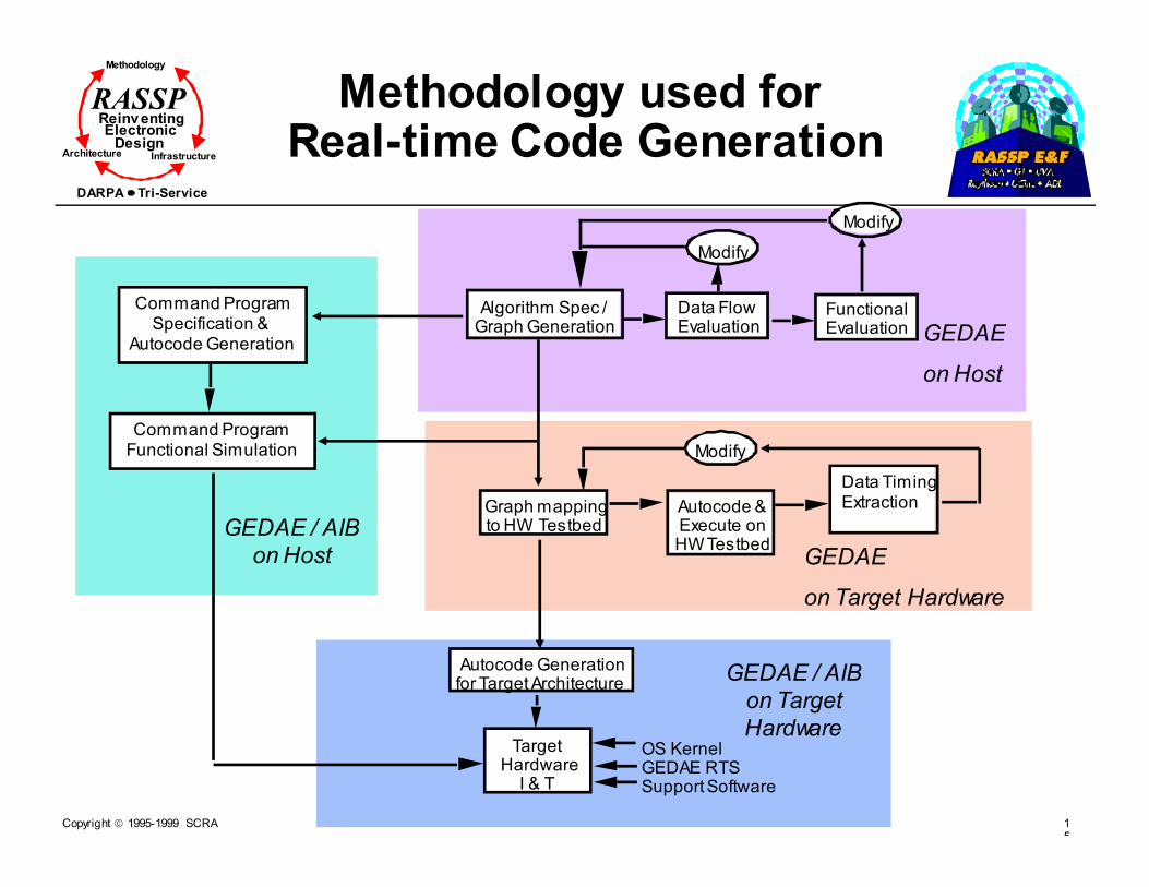
Copyright 1995-1999 SCRA 15
Methodology
Reinv entingElectronic
DesignArchitecture Infrastructure
DARPA Tri-Service
RASSP Methodology used forReal-time Code Generation
GEDAE / AIB
on Target
Hardware
GEDAE
on Host
Algorithm Spec /Graph Generation
Data FlowEvaluation
Graph mapping to HW Testbed
Modify
Autocode & Execute onHW Testbed
Modify
Autocode Generationfor Target Architecture
Target HardwareI & T
OS KernelGEDAE RTSSupport Software
Command ProgramSpecification &
Autocode Generation
Command ProgramFunctional Simulation
GEDAE
on Target Hardware
GEDAE / AIB
on Host
FunctionalEvaluation
Modify
Data Timing Extraction

Copyright 1995-1999 SCRA 15
Methodology
Reinv entingElectronic
DesignArchitecture Infrastructure
DARPA Tri-Service
RASSPGraph Development Process
Graph Generation
� Determine Data Flow �Scalar stream, vectors, matrices, variable
vectors/matrices, structures
�Instantiation
�Queue sizing
� Determine Functional Flow � Custom vs. built-in primitives
� Tradeoffs include - entry time, readability, maintainability, debug and test, runtime performance, portability, distribution
� Determine baseline hierarchy
� Write Custom Primitives� Written in portable math library (e-library)
� Can make direct call to custom c-function
� Enter Graph and Parameters
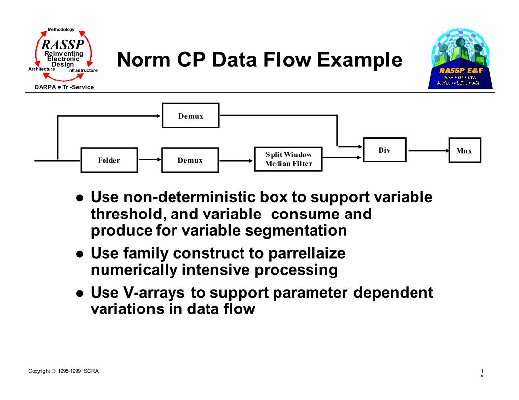
Copyright 1995-1999 SCRA 16
Methodology
Reinv entingElectronic
DesignArchitecture Infrastructure
DARPA Tri-Service
RASSP
Norm CP Data Flow Example
� Use non-deterministic box to support variable threshold, and variable consume and produce for variable segmentation
� Use family construct to parrellaize numerically intensive processing
� Use V-arrays to support parameter dependent variations in data flow
Folder DemuxSplit Window
Median Filter
Div
Demux
Mux

Copyright 1995-1999 SCRA 16
Methodology
Reinv entingElectronic
DesignArchitecture Infrastructure
DARPA Tri-Service
RASSPNorm CP GEDAE Graph

Copyright 1995-1999 SCRA 16
Methodology
Reinv entingElectronic
DesignArchitecture Infrastructure
DARPA Tri-Service
RASSP Addition of new customprocessing primitives
Data transfer separated from application module design
— programmer only concerned with application specific code
• Data flow specification separated from application module
— programmer provides simple specification wrapper to encapsulate module
GEDAE Function Box
split
in re
im
Data Processing Function
split (in, re, im)
derive output arrays ("re" and "im") according to some algorithms applied to input array ("in").
Data Flow Requirements
applysplit ( )
1. Get inputs and outputs
2. Call split data processing function 3. Note data produced and consumed
Standard Interface
Module Code

Copyright 1995-1999 SCRA 16
Methodology
Reinv entingElectronic
DesignArchitecture Infrastructure
DARPA Tri-Service
RASSP GEDAE™ CODE Generation
#include <stddef.h>
#include <staticFunction.h>
typedef struct {
float *a;
int N_a;
float *b;
int N_b;} StateRec, *State;
static OffsetTable OT[] = {
{VALUE_OFFSET, "a"}, {SIZE_OFFSET , "a"},
{VALUE_OFFSET, "b"}, {SIZE_OFFSET , "b"},
{0,0}
};
static int Offsets[] = {
offsetof(StateRec,a), offsetof(StateRec,N_a),
offsetof(StateRec,b), offsetof(StateRec,N_b),
-1
};
static int Offset(char *name, OffsetType type) {
return internal_offset(name,type,OT,Offsets);
}
#include <e_vadd.h>
static void Apply(void *vstate) {
State state = vstate;
float *b = (state->b);
float *a = (state->a);
int _size_a = state->N_a;
e_vadd(a,1,b,1,a,1,_size_a);
}
void Init__embeddable__stream__add(void) {
OCreateStaticBoxClass("embeddable/stream/add",sizeof(StateRec),
"offset", Offset,
"apply", Apply,
0);
}
Name: add
Type: static
Comment: "Addition
out = a + b"
Input: {
stream float a;
stream float b;
}
Output: {
inplace stream float out=a;
}
Include: {
#include <e_vadd.h>
}
Apply: {
e_vadd(a,1,b,1,a,1,size(a)); /* vector add */
}
Library Function
embeddable/stream/add
Automatic Code
Generation
C source
of add.c
GEDAE™ library functions are simple
to add and generated source code is not
difficult to read

Copyright 1995-1999 SCRA 16
Methodology
Reinv entingElectronic
DesignArchitecture Infrastructure
DARPA Tri-Service
RASSPTest and Integration Process
� Test Data Flow on Host� Primitive connection ensures data flow compatibility
prior to test
� Box table/data table, show Q's and boxes graphically facilitate debug of data flow
� Optimization of memory
� Test Functional Flow on Host� Scope and/or files facilitates debug of functional flow
� Standard debuggers used to debug custom c-code
� Collect Timelines Host� Identify processing requiring further optimization
� Embed on target hardware verify performance � Optimize partitioning and mapping for load balancing
� Optimize transfer methods
� Identify processing requiring further optimization

Copyright 1995-1999 SCRA 16
Methodology
Reinv entingElectronic
DesignArchitecture Infrastructure
DARPA Tri-Service
RASSP Data Flow and MemoryUsage Visualization
• Static Schedule Table displays detailed information about statically scheduled processes
— execution sequence
— memory usage vs. time
— process execution time
Data generation
Data in use
Data storage
In-placecalculation
Data consumption
Memory Usage Time
Execution Sequence

Copyright 1995-1999 SCRA 16
Methodology
Reinv entingElectronic
DesignArchitecture Infrastructure
DARPA Tri-Service
RASSP
Time Line Visualization
• GEDAE provides visualization from both hardware and software perspectives
• Trace Table displays detailed timelines and processor loading for each function and data transfer
Hardware profile
Compute time
Data flow profile
I/O time
Software profile

Copyright 1995-1999 SCRA 16
Methodology
Reinv entingElectronic
DesignArchitecture Infrastructure
DARPA Tri-Service
RASSP ETC4ALFS TimelineExample
� Timeline of graph running on host
� First run identifies a problem
� ADT initialization routines need to be done on reset method at graph initialization time

Copyright 1995-1999 SCRA 16
Methodology
Reinv entingElectronic
DesignArchitecture Infrastructure
DARPA Tri-Service
RASSPTop Level Graph

Copyright 1995-1999 SCRA 16
Methodology
Reinv entingElectronic
DesignArchitecture Infrastructure
DARPA Tri-Service
RASSP
ETC4ALFS Top Level Graph
The graph is composed of� Source_Box which simulates real-time input data
� The Front end CP (cp_nd) composed of � Norm,
� FBE
� CFE.
� The Front end CW (va_ndCW) composed � Norm
� FBE
� CFE.
� A switch to control flow of data to backend graph
� The Back end composed of � SPF,
� ADT
� MPC.
� QueueManager box to sync up beam data to ping time data and other data from Command Program
� Sync_Box to tell the command program when the graph is complete with each ping of data

Copyright 1995-1999 SCRA 17
Methodology
Reinv entingElectronic
DesignArchitecture Infrastructure
DARPA Tri-Service
RASSP Hardware Architecture Description
� Two Mercury modules each with 4 Power PC processors
� Command Program on Sun workstation
Power
PC
CN ASIC
16 Meg
RAM
Power
PC
CN ASIC
16 Meg
RAM
RACE Crossbar
Power
PC
CN ASIC
16 Meg
RAM
Power
PC
CN ASIC
16 Meg
RAM
Power
PC
CN ASIC
16 Meg
RAM
Power
PC
CN ASIC
16 Meg
RAM
Power
PC
CN ASIC
16 Meg
RAM
Power
PC
CN ASIC
16 Meg
RAM

Copyright 1995-1999 SCRA 17
Methodology
Reinv entingElectronic
DesignArchitecture Infrastructure
DARPA Tri-Service
RASSP
Command Program
Command & Control System
OperatorInterface
DataProcessing
Command Program
Signal Processing System
� Fundamental Command Program Requirement
� Translate high level (user) input (e.g., stop track model, start weather mode) into lower level signal processor control commands (e.g., create queue, write graph variable)
� Forward signal processor results

Copyright 1995-1999 SCRA 17
Methodology
Reinv entingElectronic
DesignArchitecture Infrastructure
DARPA Tri-Service
RASSPAIB - Application Interface
Builder� Builds Application Programmer Interface
(API)� Each mode is an object� Methods for mode entry/exit
� Methods for submode entry/exit� Methods for execution state transition� Methods for buffering operator/DSP data
� Input� Enhanced top level graph declarations
� 90% previously generated by DSP autocode process
� Output� C source
� Future� Integrate with GEDAE GUI� Tighter integration with ObjectGeode
Used successfully to support ETC for ALFS integration -300 lines in yielded 3000 lines out
Command Program
Autocoded Application
Command Program Interface
Data Flow Interface
Signal Processing System
Views Signal
Processing
System as modes
and submodes
Presents Signal
Processing System
as graphs

Copyright 1995-1999 SCRA 17
Methodology
Reinv entingElectronic
DesignArchitecture Infrastructure
DARPA Tri-Service
RASSP
Command ProgramGEDAE™
Workstation
Command Program API
(Application Independent Interface)
Host Communication Layer
Embedded Communication Layer
Embedded Kernel
Intrinsic Function Boxes User Supplied Boxes
Command Program API(Application Specific Interface)
Layer and Conquer
•state machine that manages mode objects
•AIB- A bridge that transforms collections of graph objects into mode objects
•A wrapper hiding the signal processor implementation

Copyright 1995-1999 SCRA 17
Methodology
Reinv entingElectronic
DesignArchitecture Infrastructure
DARPA Tri-Service
RASSP ETC GEDAE Conversion Summary
� Training - 1 week
� CP frontend captured, tested, and optimized on Host -3 weeks� CP Front End is well partitioned into primitives
� CW frontend captured, tested, and and optimized on Host - 5 week� CW Front End is well partitioned into primitives
� Back End captured, tested, and optimized on Host - 2 weeks� Backend is largely unpartitioned c-code, needs further
breakdown to maximize advantages gained by using graphical data flow paradigm
� Waited for delivery of Mercury hardware and release of AIB for ~ one month

Copyright 1995-1999 SCRA 17
Methodology
Reinv entingElectronic
DesignArchitecture Infrastructure
DARPA Tri-Service
RASSP
Lesson Learned from Tool Usage
� The GEDAE development environment greatly simplified capture and test of applications targeted for real-time distributed environments.
� tools were easy to learn and use
� Concerns of team with “black box” effect of autocoding software turn out to be unfounded
� visualization aids were very effective
� insight to what the software was doing was actually better then some handcoded real-time software projects we have worked on
� The primary shortcomings of GEDAE are consistent with the level of maturity of the embedded capability which has been operational for less then a year.

Copyright 1995-1999 SCRA 17
Methodology
Reinv entingElectronic
DesignArchitecture Infrastructure
DARPA Tri-Service
RASSP
Tool Improvements
� Tool improvements made during project development
� Command program interface (AIB) added
� Improvements to facilitate data flow and test
� Automatic resizing of queues (Q) in GEDAE to minimize memory requirements and help isolate data flow problems
� Improved and added primitives for V-array support especially for dynamic (variable consume and/or produce) and non-deterministic (variable threshold) boxes
� System build (make) process improved
� Future improvements or additional features we would like to see
� Better documentation of tool needed for embedding process, documentation for graph development on host is good
� File management system is limited for large multi-user program development
� More refined methods of shared data management to reduce amount of memory usage
� Final documentation generator of graph, parameters, and command program interface would be very useful and save time
� Summaries of trace, schedule and queue tables would be useful

Copyright 1995-1999 SCRA 17
Methodology
Reinv entingElectronic
DesignArchitecture Infrastructure
DARPA Tri-Service
RASSP
Module Outline
� Introduction
� Requirements Capture
� Fixed-Point Design - A RASSP Approach
� Simulation-Based Algorithm/Functional Design
� Network-Level DSP
� Link-Level DSP
� Signal Processing Simulators
� PGM/PGSE
� RASSP Software Generation
� Summary
Copyright 1995-1999 SCRA 17
Methodology
Reinv entingElectronic
DesignArchitecture Infrastructure
DARPA Tri-Service
RASSP
Summary
� Introduced the algorithm and functional design environments for DSP
� Described the interaction between implementation and front end algorithm design
� Presented recent RASSP developments
� Executable specifications
� High-level test benches
� Simulation-based design
� Graphical and block-oriented algorithm capture
� Examples of the above

Copyright 1995-1999 SCRA 17
Methodology
Reinv entingElectronic
DesignArchitecture Infrastructure
DARPA Tri-Service
RASSP
References
[Arm95] Armstrong, J.R. , et al, “High Level Generation of VHDL Testbenches,” VHDL International
Users Forum, Spring 1995, pp 6.23 - 6.34.
[Army94] US Army Research Laboratory, The Documentation of Digital Electronic Systems with VHDL-
The Army Handbook, Preliminary Final Draft Manuscript, February 9, 1994.
[Balaban84] Balaban P., et. al “Computer-Aided Modeling, Analysis, and Design of Communications
Systems: Introduction and Issue Overview”, IEEE Journal on Selected Topics in Communications,
Jan 1984.
[Baudendistel93] Baudendistel K., Ph.D. Thesis, 1993, Georgia Institute of Technology, Atlanta, GA.
[BOSS86] Shanmugan K. S., Manning T.C. et. al, “Block-Oriented Systems Simulator (BOSS)”, IEEE ,
International Conference on Communications , 1986, pp 36.1.1-36.1.10; © IEEE 1986
[Debardelaben95] Debardelaben J., Madisetti V., “HW/SW codesign for Signal Processing - A Survey
and New Results,” Proceeding Asilomar Conference, Oct. 1995.
[Egolf] Egolf T.W., Famorazdeh S., Madisetti V.K., ”Fixed Point Codesign in DSP”, VLSI Signal
Processing VII Edited by Rabaey J., Chau P.M., Eldon J. Institute of Electrical and Electronics
Engineers, Inc. New York, NY pg 113-126 ; © IEEE 1995
[Gajski95] Gajski D., Vahid F., “Specification and Design of Embedded Hardware-Software Systems,”
IEEE Design & Test of Computers, Spring 1995, pp. 53-67.
[Gupta93] Gupta R., G. De Micheli, “Hardware-Software Cosynthesis for Digital Systems,” IEEE Design
& Test of Computers, September 1993, pp. 29-41.
[Gupta94] Gupta R., Coelho C., De Micheli G., “Program Implementation Schemes for Hardware-
Software Systems,” Computer, January 1994, pp. 48-55.

Copyright 1995-1999 SCRA 18
Methodology
Reinv entingElectronic
DesignArchitecture Infrastructure
DARPA Tri-Service
RASSP
References (Cont.)
[Kumar] Kumar S., Aylor J., Johnson B., Wulf W., “A Framework for Hardware/Software codesign,”
Computer, December 1993, pp. 39-45.
[IEEE] All referenced IEEE material is used with permission.
[Ismail95] Ismail T., Jerraya A., “Synthesis Steps and Design Models for codesign,” Computer,
February 1995, pp. 44-52.
[Jackman88] Jackman J. , Medeiros D.J., “A Graphical Methodology for Simulating Communication
Networks”, IEEE Transactions on Communications, April 1988; © IEEE 1988
[Kalavade93] Kalavade A., Lee E., “A Hardware-Software codesign Methodology for DSP Applications,”
IEEE Design & Test of Computers, September 1993, pp. 16-28.
[LMC95] Schamming B., RASSP Methodology Working Group Meeting Software Process, Lockheed
Martin Corporation, March 16, 1995., Advanced Technology Lab, Camden, NJ
[LMC-ARCH] Lockheed Martin ATL RASSP Team, RASSP MYA Specification Volume I: Introduction to
Model Year Architecture Version 1., Moorestown, NJ, September 1996.
[LMC-METH] Lockheed Martin ATL RASSP Team, RASSP Methodology Version 2.0, Moorestown, NJ,
October 1995.[LMC-METH] Lockheed Martin ATL RASSP Team, RASSP Methodology Version 2.0,
Moorestown, NJ, October 1995.
[LMC-Review] Lockheed Martin ATL RASSP Team, Final Review, Moorestown, NJ, April 1998.
[Madisetti94] Madisetti V., “Vive La Difference”, The RASSP Digest, Vol. 1, No. 1, 4th Qtr. 1994, pp. 17-
20.
[Messerschmitt84] Messerschmitt D.G., “A Tool for Structured Functional Simulation”, IEEE Journal
on Selected Topics in Communications, Jan 1984 ; © IEEE 1984

Copyright 1995-1999 SCRA 18
Methodology
Reinv entingElectronic
DesignArchitecture Infrastructure
DARPA Tri-Service
RASSP
References (Cont.)
[MMC/LMC94] Management Communication Control, Inc., Concept Definition Study Draft Technical Report, prepared for Lockheed Martin Advance Technology Lab., May 1994. Used with permission.
[MYA95]]Martin Marietta Corporation, “RASSP Model Year Architecture Document”, Internal RASSP Document, 1995.
[Myers95] Myers C., Dreiling R., “VHDL Modeling for Signal Processor Development,” Proceedings
IEEE International Conference Acoustics, Speech, and Signal Processing, May 1995.
[PGM90] Prepared by Naval Research Laboratory, Processing Graph Method: Tutorial, January 1990.
[Purvis91] Purvis M., “Hardware/Software codesign: A Perspective,” IEEE International Conference on
Software Engineering, 1991, pp. 344-351.
[RASSP94] Martin Marietta RASSP Team, RASSP Methodology Version 1.0, Moorestown, NJ, Martin
Marietta Laboratories, December 1994.
[Richards97] Richards, M., Gadient, A., Frank, G., eds. Rapid Prototyping of Application Specific Signal
Processors, Kluwer Academic Publishers, Norwell, MA, 1997
[Shanmugan88] Shanmugan K. S., “An Update on Software Packages for Simulation of Communication
Systems (Links)”, IEEE Journal on Selected Topics in Communications, 1988, vol 6, pp 5-12 ; ©
IEEE 1988
[Shanmugan89] Shanmugan K. S., et. al. “Simulation Based CAAD Tools for Communication and
Signal Processing Systems”, IEEE International Conference on Communications, 1989, vol 3, pp
1454-1461.

Copyright 1995-1999 SCRA 18
Methodology
Reinv entingElectronic
DesignArchitecture Infrastructure
DARPA Tri-Service
RASSP
References (Cont.)
[Shaw95] Shaw G., Anderson J., Madisetti V., “Assessing and Improving Current Practice in the Design of Application-Specific Signal Processors,” Proceeding IEEE International Conference Acoustics, Speech, and Signal Processing, May 1995.
[Thomas93] Thomas D., Adams J., Schmit H., "A Model and Methodology for Hardware-Software
codesign,” IEEE Design & Test of Computers, September 1993, pp. 6-15.
[Vahey95] Vahey M., et al., “A Virtual Prototype VHDL Development Methodology,” VHDL International
Users Forum, Spring 1995, pp. 3.17-3.25.