Embed Size (px)
Citation preview

Outboard Engines
*356763*Printed in the United States.© 2012 BRP US Inc. All rights reserved.TM, ® and the BRP logo are registered trademarks of Bombardier Recreational Products Inc. or its affiliates.
DSS12573I 1 of 4
WATER PUMP IMPELLER KIT, P/N 5008972
APPLICATIONUse this instruction sheet when installing the above water pump repair kit on 2009 and newerEvinrude E-TEC® 25 – 30 HP outboards. DO NOT install on any other models.
SAFETY INFORMATION
The following symbols and/or signal wordsmay be used in this document:
Indicates an instruction which, ifnot followed, could severely damage enginecomponents or other property.
These safety alert signal words mean:
ATTENTION!BECOME ALERT!YOUR SAFETY IS INVOLVED!
For safety reasons, this kit must be installed by anauthorized Evinrude®/Johnson® dealer. Thisinstruction sheet is not a substitute for workexperience. Additional helpful information may befound in other service literature.
DO NOT perform any work until you have read andunderstood these instructions completely.
Torque wrench tightening specifications muststrictly be adhered to.
Should removal of any locking fastener (lock tabs,locknuts, or patch screws) be required, alwaysreplace with a new one.
When replacement parts are required, useEvinrude/Johnson Genuine Parts or parts withequivalent characteristics, including type, strengthand material. Use of substandard parts could resultin injury or product malfunction.
Always wear EYE PROTECTION ANDAPPROPRIATE GLOVES when using power tools.
Unless otherwise specified, engine must be OFFwhen performing this work.
Always be aware of parts that can move, such asflywheels, propellers, etc.
Some components may be HOT. Always wait forengine to cool down before performing work.
If you use procedures or service tools that are notrecommended in this instruction sheet, YOUALONE must decide if your actions might injurepeople or damage the outboard.
This instruction sheet may be translated into otherlanguages. In the event of any discrepancy, theEnglish version shall prevail.
TO THE INSTALLER: Give this sheet and theoperating instructions to the owner. Advise theowner of any special operation or maintenanceinformation contained in the instructions.
TO THE OWNER: Save these instructions in yourowner’s kit. This sheet contains informationimportant for the use and maintenance of yourengine.
A DANGER
Indicates a hazardous situation which, ifnot avoided, will result in death or seriousinjury.
A WARNING
Indicates a hazardous situation which, ifnot avoided, could result in death or seri-ous injury
A CAUTION
Indicates a hazardous situation which, ifnot avoided, could result in minor or mod-erate personal injury.
NOTICE

2 of 4
WATER PUMP IMPELLER KIT
DISASSEMBLY
Remove gearcase from outboard. Refer toappropriate Service Manual.
Pull up on the driveshaft and remove thedriveshaft with the water pump assembly fromthe gearcase. Remove the water pumpassembly for the drive shaft.
Remove the impeller plate and gasket. Discardthe gasket.
Remove the water pump grommet, all O-rings,and the shift rod bushing from the impellerhousing
INSPECTION
Check impeller for overheating, hub separation,and other wear or damage.
Check liner and wear plate for scoring, distortion,and impeller material transfer.
Inspect the housing for cracks or melting.
Ref P/N Name of Part Qty5008972 WATER PUMP REPAIR KIT 1
1 325537 *GASKET 12 328755 *PLATE 13 328753 *SEAL 14 5008968 *WATER PUMP IMPELLER KIT 15 344470 **KEY 16 5008967 **IMPELLER 17 355169 **SPRING (Pressure Relief Valve) 18 355209 **SPRING (Thermostat) 19 328751 *CUP 110 554545 *O-RING 111 353590 *SCREW M6X25 612 393632 *IMPELLER HOUSING 113 328754 *BUSHING 114 302497 *GROMMET 115 301877 *O-RING 116 5007770 *SEAL & PIN ASSEMBLY 1
A Triple Guard GreaseC Adhesive 847J Gearcase Lubricant
9
10
2
1
3
65
12
15
13
14
16
11
478
A
J
C
C
C
008020
1. Screws 007655
1
1. Impeller Plate 007656
1

3 of 4
ASSEMBLY
Oil and install the shift rod bushing into theimpeller housing.
Apply Triple-Guard grease to the shift rod O-ringand install below bushing.
Apply a thin bead of Adhesive 847 in the innergroove of the impeller housing and install a newimpeller cup O-ring.
Lightly coat the exterior of the impeller cup withGasket Sealing Compound. Align tabs of impellercup with location holes of impeller housing andinstall the impeller cup into the impeller housing.
Lightly coat the inside of the impeller cup with oil.With a counterclockwise rotation, install theimpeller into the impeller cup.
IMPORTANT: The sharp edge of cam slot in theimpeller is the leading edge during rotation.
Apply Adhesive 847 to the outer seal groove ofthe impeller housing. Install a new seal into thegroove.
Lightly oil pinion spines of the driveshaft. Slide thedriveshaft through the impeller housing andimpeller until drive cam flat of the driveshaft isbelow the impeller. Align drive cam flat withgroove of the impeller. Install the impeller drivecam.
1. Shift rod bushing 007657
1. Shift rod o-ring2. Impeller cup o-ring
007658
1. Tabs, impeller cup1. Location holes
007659
1
2
1
21
1. Impeller2. Sharp edge
007660
1. Seal 007661
1. Drive cam 007662
21
1
1

4 of 4
Sharp edge of the cam is leading edge duringdriveshaft rotation. Slide the impeller housingdown the driveshaft. Engage the impeller withthe cam.
Make sure the impeller is oriented properly andengages the impeller cam properly. Seriouspowerhead damage will result of impeller cam isdisplaced.
Lightly coat both sides of a new impeller plategasket with Gasket Sealing Compound. Placegasket on the gearcase.
Place the impeller plate over the gasket.
Slide the driveshaft down into the gearcase andengage the pinion.
Turn the driveshaft until holes of the impellerhousing are aligned with holes of the gearcase.Apply Gasket Sealing Compound to threads ofthe impeller housing screws. Tighten the screwsto a torque of 60 to 84 in. lbs. (7 to 5 N·m).
Apply Adhesive 847 to outside of water tubegrommet. Install grommet and locate grommetbosses into holes of impeller housing.
Install gearcase on outboard. Refer toappropriate Service Manual. Tighten gearcasemounting screws to a torque of 128 to 146 in. lbs.(1405 to 16.5 N·m).
2010 and Older Models ONLY
Install the pressure relief valve and thermostatsprings provided with Water Pump Impeller Kit,P/N 5008968. Refer to instructions provided withWater Pump Impeller Kit or appropriate ServiceManual.
Failure to install impeller assem-bly and springs as a set can result in:A cold running engine, if the impeller isinstalled without the pressure relief valveand thermostat springs.An engine overheat, if the pressure reliefvalve and thermostat springs are installedwithout the new impeller.
Start outboard. Check water pump operation.Check engine operating temperature. Refer toappropriate Service Manual for enginetemperature check procedure.
DO NOT run outboard without awater supply to the outboard’s cooling sys-tem. Cooling system and/or powerhead dam-age could occur. Be sure the water intakescreens are below the water surface.
1. Driveshaft rotation2. Drive cam
CO2995
007663
2
1
1. Grommet 007664
1
NOTICE
NOTICE

Outboard Engines
KIT DE TURBINE DE POMPE À EAU, N° RÉF. 5008972
APPLICATIONUtiliser cette fiche d'instructions lors de l'installation du kit de réparation de pompe à eaususmentionné sur les moteurs Evinrude E-TEC® 25–30 cv et postérieurs. Ne l’installer sur AUCUNautre modèle.
INFORMATIONS SUR LA SÉCURITÉ
Il se peut que les symboles et/ou mots indica-tifs suivants apparaissent dans le présentdocument :
Indique une instruction qui, si ellen'est pas suivie, risque de gravementendommager les composants du moteur oude causer d'autres dégâts matériels.
Ces mots destinés à attirer l’attention sur la sécuri-té signifient :
ATTENTION !ÊTRE VIGILANT !LA SÉCURITÉ EST EN JEU !
Pour des raisons de sécurité, ce kit doit être installépar un concessionnaire agrééEvinrude®/Johnson®. Cette fiche d'instructions neremplace pas l’expérience professionnelle. Lesautres documents relatifs à l'entretien comportentdes compléments d'information utiles.
N'effectuer AUCUNE opération avant d'avoir lu etveillé à bien comprendre ces instructions.
Les spécifications de serrage par clédynamométrique doivent être strictementrespectées.
Si le retrait d'une fixation bloquante quelconque(languettes de verrouillage, écrous de blocage ouvis de réparation) s'avère nécessaire, toujours laremplacer par une neuve.
Lorsque des pièces de rechange sont nécessaires,utiliser des pièces d’origine Evinrude/Johnson oudes pièces ayant des caractéristiqueséquivalentes, y compris le type, la résistance et lematériau. L’utilisation de pièces de qualitéinférieure peut entraîner des blessures ou unmauvais fonctionnement du produit.
Toujours porter des LUNETTES DEPROTECTION ET DES GANTS APPROPRIÉSpour utiliser des outils électriques.
Sauf indication contraire, le moteur doit êtreARRÊTÉ pour effectuer une telle opération.
Toujours faire attention aux pièces mobiles tellesque volants-moteurs, hélices, etc.
Certains composants peuvent être CHAUDS.Toujours laisser le moteur refroidir avant detravailler dessus.
S’il utilise des procédures ou des outils d’entretienqui ne sont pas recommandés dans cette fiched'instructions, SEUL LE TECHNICIEN doit décidersi ses actions risquent de blesser des personnesou d’endommager le moteur hors-bord.
Il se peut que la présente fiche d'instructions soittraduite dans d'autres langues. En cas de disparité,c’est la version anglaise qui prévaudra.
À L’INTENTION DE L’INSTALLATEUR :Remettre cette fiche ainsi que les instructionsd'utilisation au propriétaire. Attirer l’attention dupropriétaire sur toute information particulièred’utilisation et d’entretien contenue dans cesinstructions.
A DANGER
Indique une situation dangereuse qui, sielle n'est pas évitée, entraînera la mort oudes blessures graves.
A WARNING
Indique une situation dangereuse qui, sielle n'est pas évitée, risque d'entraîner lamort ou des blessures graves.
A CAUTION
Indique une situation dangereuse qui, sielle n’est pas évitée, risque d’entraînerdes blessures légères ou moyennementgraves.
AVIS
*356763*Imprimé aux États-Unis.© 2012 BRP US Inc. Tous droits réservés.TM, ® et le logo BRP sont des marques déposées de Bombardier Recreational Products Inc. ou de ses filiales.
DSS12573I 1 / 6
À L’INTENTION DU PROPRIÉTAIRE : Conserver ces instructions dans le kit du propriétaire. Cette fichedonne des informations importantes pour l’utilisation et l’entretien du moteur.
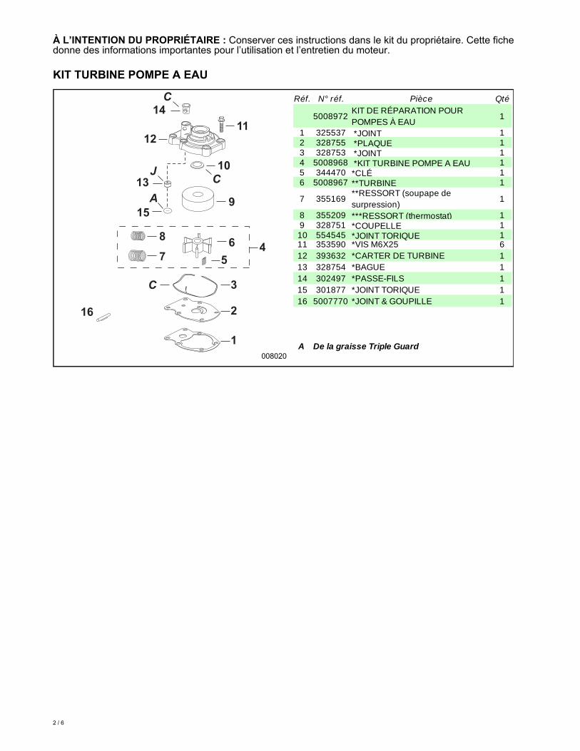
KIT TURBINE POMPE A EAU
Réf. N° réf. Pièce Qté
5008972KIT DE RÉPARATION POUR POMPES À EAU
1
1 325537 *JOINT 12 328755 *PLAQUE 13 328753 *JOINT 14 5008968 *KIT TURBINE POMPE A EAU 15 344470 *CLÉ 16 5008967 **TURBINE 1
7 355169**RESSORT (soupape de surpression)
1
8 355209 ***RESSORT (thermostat) 19 328751 *COUPELLE 110 554545 *JOINT TORIQUE 111 353590 *VIS M6X25 612 393632 *CARTER DE TURBINE 113 328754 *BAGUE 114 302497 *PASSE-FILS 115 301877 *JOINT TORIQUE 116 5007770 *JOINT & GOUPILLE 1
A De la graisse Triple Guard
9
10
2
1
3
65
12
15
13
14
16
11
478
A
J
C
C
C
008020
2 / 6
DÉMONTAGE
Retirer le boîtier d'engrenages du hors-bord. Sereporter au manuel d'entretien approprié.
Tirer sur l’arbre d’entraînement et le sortir, avecl’assemblage de pompe à eau, du boîtierd’engrenages. Dégager l’assemblage de pompeà eau de l’arbre d’entraînement.
Déposer le plateau de turbine et le joint. Jeter lejoint.
Retirer la bague de la pompe à eau, tous lesjoints toriques et la bague de la tige decommande de sens de marche du carter deturbine.
INSPECTION
Vérifier la turbine pour voir si elle présente dessignes de surchauffe, de séparation du moyeu,d’usure ou de dommages.
Vérifier la chemise et la plaque d’usure pour voirsi elles sont rayées ou déformées, ou si ellesprésentent des signes de transfert de matière dela turbine.
Examiner le carter pour voir s’il est fêlé ou s’ilfond.
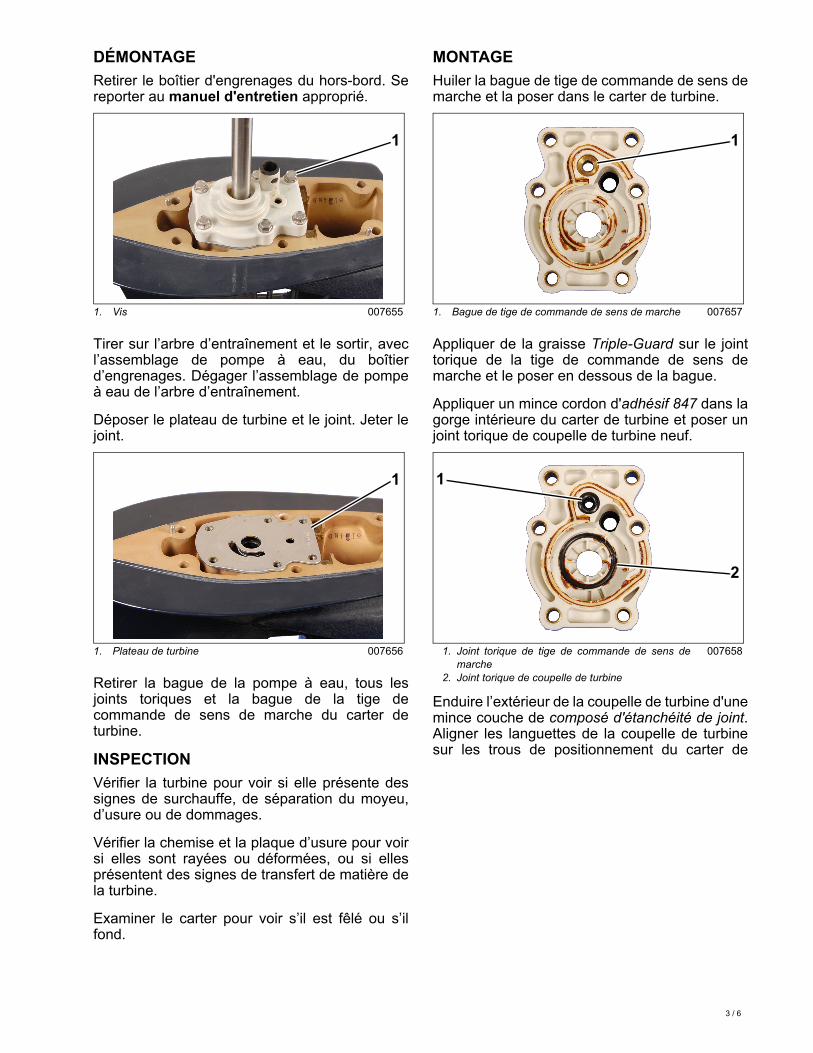
MONTAGE
Huiler la bague de tige de commande de sens demarche et la poser dans le carter de turbine.
Appliquer de la graisse Triple-Guard sur le jointtorique de la tige de commande de sens demarche et le poser en dessous de la bague.
Appliquer un mince cordon d'adhésif 847 dans lagorge intérieure du carter de turbine et poser unjoint torique de coupelle de turbine neuf.
Enduire l’extérieur de la coupelle de turbine d'unemince couche de composé d'étanchéité de joint.Aligner les languettes de la coupelle de turbinesur les trous de positionnement du carter de
1. Vis 007655
1. Plateau de turbine 007656
1
1
1. Bague de tige de commande de sens de marche 007657
1. Joint torique de tige de commande de sens demarche
2. Joint torique de coupelle de turbine
007658
1
2
1
3 / 6

turbine et poser la coupelle dans le carter deturbine.
Enduire l’intérieur de la coupelle de turbine d'unemince couche d’huile. Poser la turbine dans lacoupelle en tournant dans le sens inverse desaiguilles d’une montre.
IMPORTANT : L’arête vive de la fente de camede la turbine est le bord avant pendant la rota-tion.
Appliquer de l’adhésif 847 sur la gorgeextérieure de joint du carter de turbine. Poser unjoint neuf dans la gorge.
Huiler légèrement les cannelures de pignon del’arbre d’entraînement. Glisser l’arbred’entraînement dans le carter de turbine et laturbine jusqu’à ce que le méplat de camed’entraînement de l’arbre soit sous la turbine.Aligner le méplat de came d’entraînement et lagorge de la turbine. Poser la camed’entraînement de la turbine.
L’arête vive de la came est le bord avant lors dela rotation de l’arbre d’entraînement. Glisser lecarter de turbine vers le bas sur l’arbred’entraînement. Enclencher la turbine avec lacame.
S'assurer que la turbine est orientéecorrectement et qu’elle s’enclenchecorrectement avec sa came. Le bloc-moteurrisque d’être gravement endommagé si la camede turbine est déplacée.
Appliquer une mince couche de composéd’étanchéité de joint sur les deux côtés d’un jointde plateau de turbine neuf. Poser le joint sur leboîtier d’engrenages.
Poser le plateau de turbine sur le joint.
Glisser l’arbre d’entraînement vers le bas dans leboîtier d’engrenages et engager le pignon.
1. Languettes, coupelle de turbine1. Trous de positionnement
007659
1. Turbine2. Arête vive
007660
1. Joint 007661
21
21
1
1. Came d’entraînement 007662
1. Rotation de l’arbre d’entraînement2. Came d’entraînement
CO2995
1
2
1
4 / 6

Faire tourner l’arbre d’entraînement jusqu’à ceque les trous du carter de turbine soient alignéssur les trous du boîtier d’engrenages. Appliquerdu composé d'étanchéité de joint sur le filetagedes vis du carter de turbine. Serrer les vis à uncouple de 60 à 84 lb-po (7 à 5 N·m).
Appliquer de l’adhésif 847 sur l’extérieur de labague du tube à eau. Poser la bague et placerses bossages dans les trous du carter de turbine.
Poser le boîtier d’engrenages sur le moteurhors-bord. Se reporter au manuel d'entretienapproprié. Serrer les vis de montage du boîtierd’engrenages à un couple de 128 à 48 lb-po(14,5 à 16,5 N·m).
Modèles 2010 et antérieurs UNIQUE-MENT
Installer les ressorts pour soupape desurpression et thermostat fournis avec le kit deturbine de pompe à eau, n° réf. 5008968. Sereporter aux instructions fournies avec le kit deturbine de pompe à eau ou au manueld'entretien correspondant.
Le fait de ne pas installer en blocl'ensemble roue à hélice et ressorts peutavoir les résultats suivants :Le moteur fonctionne mal si la roue à héliceest installée sans les ressorts pour soupapede surpression et thermostat.Le moteur est en surchauffe si les ressortspour soupape de surpression et thermostatsont installés sans la roue à hélice neuve.
Faire démarrer le moteur hors-bord. Vérifier lefonctionnement de la pompe à eau. Vérifier latempérature de fonctionnement du moteur.Consulter le manuel d'entretien correspondantpour la procédure de contrôle de la températuredu moteur.
NE PAS faire tourner le moteurhors-bord sans que son circuit de refroidis-sement soit alimenté en eau. Ce circuit et/oule bloc-moteur risqueraient d’être endomma-gés. S'assurer que les crépines de prisesd’eau sont immergées.
007663
1. Bague 007664
1
AVIS
AVIS
5 / 6

6 / 6