Embed Size (px)
Citation preview

www.datatranslation.com US/Canada (800) 525-8528 EUropE/aSia +49 (0) 7142-9531–0
High Performance Ethernet Instrument Module for Sound & Vibration
DT8837
The DT8837 is a highly accurate multi-channel module that is ideal for sound and vibration measurements. All the I/O channels are completely isolated from each other and from the computer, allowing noise-free data to be sampled in tough industrial environments. Four 24-bit IEPE (ICP®) sensor inputs, a 24-bit D/A stimulus output, a 31-bit tachometer channel are synchronized to provide data streams that are matched in time for field or laboratory use.
The DT8837 offers a readback analog output channel in the analog input data stream and provides special measurement modes for precisely correlating the tachometer input with the A/D sensor measurements.
The TCP/IP Ethernet operation allows measurements to be monitored locally or at other remote sites. Up to 16 instrument modules maybe stacked for parallel operation of 64 accelerometer or voltage inputs. These modules are synchronized via the Wired Trigger Bus and can be externally triggered in various ways.
All inputs use ISO-Channel technology, meaning that the 4 IEPE analog inputs, the analog output, tachometer, and 4 robust digital outputs, are galvanically isolated up to ±500V from each other and allow a separate return for each signal. This protection mechanism guarantees freedom from ground loops and noise.
Key Features:
• IEPE or Voltage inputs • ISO-Channel™ provides ±500V galvanic isolation
channel-to-channel for all I/O signals and grounds • 4 Simultaneous, 24-bit Delta-Sigma A/D channels
for high resolution measurements, or use as 4 IEPE inputs for direct sensor connection
• Input range of ±10V with gains of 1 and 10, software selectable
• 4mA current source with 24V compliance voltage, software selectable
• AC/DC coupling, software selectable• Sample rate up to 52.734 kHz, programmable
• Total In Sync Data• ADCs, Tachometer, Counter and DAC feedback
channels sampled simultaneously and can be selectively included in input sample data
• Two 32-bit counters for measuring tachometer, gate and ADC conversion relationships
Figure 1. The DT8837, a 1U 1/2 rack instrument module, uses direct BNC connections to the four parallel ISO-Channel analog inputs and the analog output. Connections for the tachometer, counters, digital output, and Ethernet are available on the rear panel.
Figure 2. Up to sixteen modules may be used in parallel to connect a possible 64 direct voltage or IEPE channels, each synchronized in a master/slave configuration. The picture above shows four instrument modules in such a configuration.
Summary of Features
Analog Input
4 Isolated Channels (ISO-Channel)
24-bit Resolution
AC/DC/4mA
Max Sampling Rate/Ch. Up to 52.7kHz
1 Tachometer
Tachometer Measurement Modes 3
Simultaneous with Analog Output
Analog Output
1 Isolated Channel (ISO-Channel)
24-bit Resolution
Sampling Rate Programmable
Max Sampling Rate/Ch. Up to 52.7kHz
Buffer Mode
Simultaneous with Analog Input
4 Isolated Digital Outputs, ±30V @ 400mA
External Trigger
Multiple Module Synchronization
Ethernet, TCP/IP (Features continued on page 4)
www.idm-instrumentos.es [email protected]

2www.datatranslation.com US/Canada (800) 525-8528 EUropE/aSia +49 (0) 7142-9531–0
ISO-ChannelTM
Inputs
External Trigger
ISO-ChannelTM
Output10kHzFilter
Analog OutputBNC
24-Bit D/AConverter
±500 V
±500 V16-Bit A/DConverter
Clock
Timing& Control
ExternalPower
RESET
InputFIFO
PLLProgrammable
Clock
WiredTrigger
Bus(WTB)
15 Pin DConn
DigitalOut
±250 V
±250 V
±250 V
Readback Channel
WaveSampleBuffer
Status LEDs
RJ-45Ethernet10/100Base-T
Interface
+/-500 VoltsGalvanic Isolation
Galvanic Isolation
Legend
Up to ±30V @ 400mA
31-BitTachometer& 2 Counters
±500 V24-BitA/D
x1 / 10Analog InputBNC 1
AC-DCCoupling
1M
4mA IEPE Current Source
+24 VoltsCompliance
±500 V24-BitA/D
x1 / 10Analog InputBNC 2
AC-DCCoupling
1M
4mA IEPE Current Source
+24 VoltsCompliance
±500 V24-BitA/D
x1 / 10Analog InputBNC 3
AC-DCCoupling
1M
4mA IEPE Current Source
+24 VoltsCompliance
±500 V24-BitA/D
x1 / 10Analog InputBNC 4
AC-DCCoupling
1M
4mA IEPE Current Source
+24 VoltsCompliance
Figure 3. The design of the DT8837 incorporates galvanically isolated channels, the wired trigger bus for synchronizing acquisition on multiple instrument modules, and full Ethernet (LXI) compatibility.
www.idm-instrumentos.es [email protected] Tel. 913000191
3www.datatranslation.com US/Canada (800) 525-8528 EUropE/aSia +49 (0) 7142-9531–0
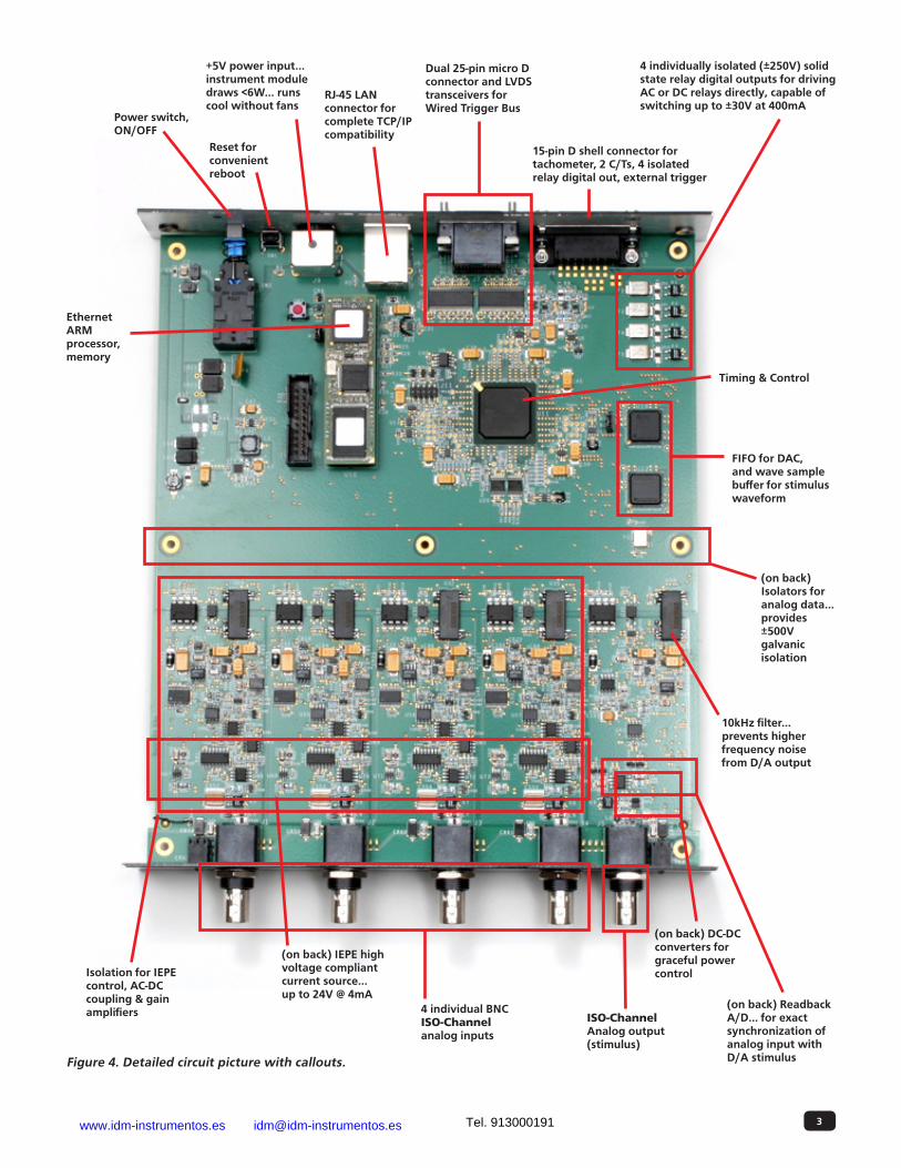
4 individually isolated (±250V) solid state relay digital outputs for driving AC or DC relays directly, capable of switching up to ±30V at 400mA
15-pin D shell connector for tachometer, 2 C/Ts, 4 isolated relay digital out, external trigger
Dual 25-pin micro D connector and LVDS transceivers for Wired Trigger Bus
RJ-45 LAN connector for complete TCP/IP compatibility
+5V power input... instrument module draws <6W... runs cool without fans
Reset for convenient reboot
Power switch, ON/OFF
FIFO for DAC, and wave sample buffer for stimulus waveform
(on back) Isolators for analog data... provides ±500V galvanic isolation
Timing & Control
Ethernet ARM processor, memory
Isolation for IEPE control, AC-DC coupling & gain amplifiers
(on back) IEPE high voltage compliant current source... up to 24V @ 4mA
4 individual BNC ISO-Channel analog inputs
ISO-Channel Analog output (stimulus)
10kHz filter... prevents higher frequency noise from D/A output
(on back) DC-DC converters for graceful power control
(on back) Readback A/D... for exact synchronization of analog input with D/A stimulusFigure 4. Detailed circuit picture with callouts.
www.idm-instrumentos.es [email protected] Tel. 913000191

4www.datatranslation.com US/Canada (800) 525-8528 EUropE/aSia +49 (0) 7142-9531–0
• Continuous Waveform Output• One 24-bit D/A Converter, ±10 volts• On-Board memory allows continuous waveform
output without host communication (2 – 128k Samples)
• Sample rate up to 52.734 kHz, Programmable • 16-bit feedback ADC to allow correlation of
output stimulus with sampled input data• Robust Digital Outputs
• 4 digital outputs can switch up to ±30V @ 400 mA... Ideal for driving mech relays or motors
• Module Expansion• Stack up to 16 modules for parallel operation of
64 channels (IEPE or voltage) via the Trigger Bus• Several Trigger options: Software, External TTL
trigger input, Variable threshold trigger, Trigger Bus, LAN Trigger Packet
• Synchronization reference clock, ADC sync and trigger input/output via Trigger Bus for synchronizing multiple up to 16 instrument modules
Analog Inputs
The DT8837 instrument module supports four, differential analog input channels. All analog input channels are simultaneously clocked. The DT8837 instrument module uses 24-bit Delta-Sigma analog-to-digital converters (ADCs) that provide anti-aliasing filters based on the clock rate. These filters remove aliasing, which is a condition where high frequency input components erroneously appear as lower frequencies after sampling. In addition, the DT8837 instrument module can acquire data from a tachometer, two counter/timers, and the analog output readback channel.
Analog Inputs with IEPE Functions
Applications that require accelerometer, vibration, noise, or sonar measurements often use IEPE sensors. IEPE conditioning is built-in to the analog input circuitry of the DT8837 instrument module. The instrument module supports the following software-programmable IEPE functions for each of the four analog inputs:
• Excitation current source – You can enable or disable the use of a 4mA current source with 24V compliance voltage to allow wide dynamic range without distortion. By default, the excitation current source is disabled.
• Coupling type – You can select whether AC coupling or DC coupling is used. By default, DC coupling is selected.
Break detection is provided if using DC coupling with the 4mA excitation current source and the voltage input is positive, full scale.
Delta-Sigma A/D Converters
The DT8837 instrument module includes a 24-bit Delta-Sigma ADC for each analog input channel. With built-in anti-aliasing filters, Delta-Sigma ADCs offer superior AC performance in noise and vibration applications... advantages include:
• Reduce noise and improve accuracy by oversampling each input
• Eliminate errors that result from aliasing and high frequency noise
• Provide excellent low-level signal-to-noise performance, which improves dynamic accuracy on low level signals
• Provide excellent differential linearity, which ensures consistently accurate data conversion across the full input range
Tachometer Input
The DT8837 accepts one 31-bit tachometer input signal on the input/output connector. You can measure the frequency or period of the tachometer input signal by reading the value of the tachometer input channel in the analog input stream. The frequency or period measurement allows you to calculate the rotation speed of tachometer input signals. The tachometer is implemented with a 32-bit counter/timer, however, the measurement is contained in the lower 31 bits; the 32nd bit (MSB) is used as a data flag to indicate new or old data.
Counter Input Channels
The DT8837 provides two 32-bit counter channels that can be read as part of the analog input stream. The counters help the user correlate the analog input with digital positional input. They can measure the time between the selected rising or falling edge of the tachometer or gate input or of an ADC conversion and the selected rising or falling edge the tachometer or gate input or of an ADC conversion.
(Features continued from page 1)
www.idm-instrumentos.es [email protected] Tel. 913000191

5www.datatranslation.com US/Canada (800) 525-8528 EUropE/aSia +49 (0) 7142-9531–0
ISO-Channel Front End Design Yields Strong User Advantages
Many industrial environments present noise conditions that are very challenging in achieving precise measurements. Each ISO-Channel input is designed to isolate it from any other input or any other return path. It has its own signal return that is referenced to its input signal. Therefore, analog input 1 has its analog return 1. This means that other “grounds” or return paths from other signals or from the computer have no ability to interfere with an ISO-Channel input and return.
A single ISO-Channel analog input is shown in Fig 5. The input protection circuitry is for ESD prevention. Then a signal path provides direct DC connection or AC coupling via a software enabled opto analog switch. This enables a noise-free switching mechanism.
Direct IEPE connections are achieved through a stable, precision current source of 4mA with 24V compliance. This allows accelerometers for vibration measurements to be directly connected to the analog input and easily measured.
At the input to the auto-zero amplifier a low frequency pass filter allows signals down to 0.1 Hz to pass for measuring seismic or low frequency vibration. The signal from the analog input is converted with a 24-bit sigma delta A/D using a precision voltage reference, accurate to 8ppm per degree C. This reference is stabilized from any voltage variances. The sigma delta A/D is used to prevent anti-aliasing by preventing unwanted harmonics.
The analog input to the 24-bit A/D is referenced to the signal return. It is then isolated from the PC ground and other returns through an inductive isolator.
ESD Protection
Stable, PrecisionCurrent Source4mA @ 24V Precision
Reference
24-bitSigma-Delta
A/DIsolation
DC-DCSync toMaster Clock
IsolatedPowerSupply
AutoZeroAmp
AC-DCCoupling
AnalogInput
AnalogReturn
ISO-Channel
0.1Hz
-3dB
Signal Bandwidth Response
Figure 5. A single ISO-Channel path. There are four ISO-Channel analog inputs and one ISO-Channel analog output.
www.idm-instrumentos.es [email protected] Tel. 913000191

6www.datatranslation.com US/Canada (800) 525-8528 EUropE/aSia +49 (0) 7142-9531–0
Input Buffers
The DT8837 uses an 8 MB input buffer for storing data from each of up to 8 enabled input channels (analog input channels 1, 2, 3, 4, tachometer input channel, counter/timer 1, counter/timer 2, and the analog output readback channel). One sample from each of the enabled input channels is called a scan.
You can specify one of the following wrap modes for the input buffer:
• Continuous wrap mode – Use this mode if you want the input operation to continue indefinitely. In this case, when the end of the input buffer is reached, the operation wraps to the beginning of the input buffer overwriting the oldest scan data with the latest scan data.
• No wrap mode – Use this mode if you want the input operation to stop automatically when the input buffer is filled.
Since the maximum input buffer size is 8 MB and each sample is 4 bytes, you can store a maximum of 2 M samples in the input buffer. If you sample each input channel at the maximum input frequency (52.734 kHz), the input buffer will fill in approximately 5 seconds (52 ksamples/s per channel).
The maximum size of data transfer over Ethernet is 32 kB. Since each sample is 4 bytes, the maximum number of samples is 8 ksamples. Therefore, if you are using continuous wrap mode, ensure that you use a tight loop to ensure that you retrieve all the samples in the input buffer before the buffer is overwritten.
Input Triggers
A trigger is an event that occurs based on a specified set of conditions. Acquisition starts when the instrument module detects the initial trigger event and stops when either the input buffer has been filled or you stop the operation. The DT8837 instrument module supports the following trigger sources for starting analog input operations: Software trigger , External digital (TTL) trigger, Analog threshold trigger, Trigger Bus, and LAN Trigger Packet.
Analog Output Channels
The DT8837 instrument module supports one 24-bit analog output channel. You can read back the value of the analog output channel through the analog input channel list. A two-pole, 10 kHz Butterworth filter is applied to prevent noise from interfering with the output signal. The analog output channel powers up to a value of 0 V ±10 mV.
Figure 6. The DT8837 provides software selectable AC and DC coupling. When AC coupling is selected, the modules provide zero ripple in the wide pass band and excellent “brick wall” anti-alias filters eliminating unwanted high frequency interference.
www.idm-instrumentos.es [email protected] Tel. 913000191

7www.datatranslation.com US/Canada (800) 525-8528 EUropE/aSia +49 (0) 7142-9531–0
A/D Clock
Tachometer Edge
A/D Clock
A/D Clock
A/D Sample that you want to correlate with rotation data
t2Rotating DeviceConnected toTachometerInput Signal
New period measurement result in input data streaming
Tacho Pulse
Period measured Tachometer input (1 revolution)Time
t2
A/D sampling rate 50 KHz (A/D conversion done) or 20 μsec
t1
New period measurementavailable(tachometer edge)
Signal from analog input ch 1
t1
X
Y
Y
X
Figure 7. By connecting a rotating device to the tachometer input of the DT8837, you can measure the frequency or period of the rotating device. The DT8837 also provides the ability to accurately measure the time between the tachometer edge and the next A/D sample or between the A/D sample and the next tachometer edge, so that you can precisely correlate A/D data with rotation data.
For example, assume that you want to correlate A/D sample X from analog channel 1 to an angular position of the rotating device. This can be accomplished by using a tachometer signal that always occurs at the top, center position of the rotating device as a reference and measuring the time between the tachometer signal and the next A/D sample (Y). Since you know the frequency of the A/D sample clock (50 kHz, in this case), you know when A/D sample X occurred in relation to A/D sample Y (t2 = 1/50kHz x num samples from Y to X). By using Counter 1 to measure the time (t1) between the tachometer signal and A/D sample Y, you can calculate exactly where A/D sample X occurred in time from the tachometer signal (result = t1 + t2). Given the rotation speed of Tachometer input, you can then calculate the angular position of A/D sample X.
www.idm-instrumentos.es [email protected] Tel. 913000191

8www.datatranslation.com US/Canada (800) 525-8528 EUropE/aSia +49 (0) 7142-9531–0
Output Buffers
The DT8837 uses a 128K sample output buffer (also known as a hardware FIFO) for storing analog output data to write to the analog output channel.
You can specify the number of samples to output to the analog output channel using software. This value can range between 1 and 131072.
You can specify one of the following wrap modes for the output buffer:
• Continuous wrap mode – Use this mode if you want the output operation to continue indefinitely. In this case, when the end of the output buffer is reached, the operation wraps to the beginning of the output buffer overwriting the oldest scan data with the latest scan data.
• No wrap mode – Use this mode if you want the output operation to stop automatically when the number of samples specified has been written to the analog output channel.
Reading the Analog Output Value in the Analog Input Data Stream
You can read back the value of the analog output channel in the analog input data stream. Specify channel 8 in the analog input channel list to read back the value of the analog output channel. The software automatically synchronizes the value of the analog output channel with the analog input measurements, so that all measurements are correlated in time.
Output Triggers
A trigger is an event that occurs based on a specified set of conditions. The analog output operation starts after the trigger is received and stops when either the specified number of samples have been output or you stop the operation.
The DT8837 instrument module supports the following trigger sources for starting analog output operations: Software trigger, External digital (TTL) trigger, Analog threshold trigger, Trigger Bus, and LAN Trigger Packet.
Figure 8. The 4 isolated digital outputs offer high drive capability. They are solid state relays that are capable of switching up to ±30V @ 400mA. Either AC or DC can be switched. The internal solid state relays are poly fused to prevent any damage and they restore as soon as a short is removed
Figure 9. Multiple DT8837 instrument modules in daisy-chain configuration
Trigger Bus Terminators
Daisy-Chain Configuration
www.idm-instrumentos.es [email protected]

9www.datatranslation.com US/Canada (800) 525-8528 EUropE/aSia +49 (0) 7142-9531–0
Synchronizing Acquisition on Multiple Instrument Modules
Up to 16 instrument modules can be connected together using the Trigger Bus. Multiple DT8837 modules may be connected using a daisy-chain configuration, using the 25-pin Trigger Bus connectors (see figure 9).
When multiple instrument modules are connected together using the Trigger Bus, as shown in Figure 10, you can synchronize the start of acquisition using the LXI7 clock signals, LXI sync signal, and one of six LXI trigger signals: LXI0 to LXI5.
On the clock master, use software to set the clock source to internal and to drive out the LXI7 clock signal and LXI6 synchronization signal on the trigger bus.
Unlike when synchronizing the clock of multiple instrument modules, which requires one instrument module dedicated as the clock master, you can have more than one trigger master, if desired, to trigger multiple instrument modules. Additionally, the trigger master need not be the clock master (for example, a device other than the DT8837 can generate the trigger for the DT8837 instrument modules, if desired). Figure 11 shows an example of using two DT8837 trigger masters on the Trigger Bus.
On the trigger master, use software to set the trigger source to software trigger, external digital trigger, analog threshold trigger, or LAN trigger packet (LAN0 to LAN7). Then, use software to drive out the LXI trigger signal (LXI0 to LXI5) on the Trigger Bus.
While a trigger master can drive out more than one trigger signal on the Trigger Bus, the slave can accept only one trigger signal to start the analog input operation. On each slave, use software to select the clock source as LXI7 and the trigger signal (LXI0 to LXI5) that was driven out by the trigger master on the Trigger Bus.
Once the master is triggered, the specified LXI trigger signal is driven out on the Trigger Bus to all slaves that were configured to accept it. Acquisition starts on the first sample after the trigger is received.
LAN Trigger Packets
When multiple DT8837 instrument modules are connected together over the local area network (LAN), as shown in Figure 12, Synchronizing the Start of Acquisition When Triggering you can synchronize the start of acquisition by transmitting one of eight LAN trigger packets (LAN0 to LAN7) over the network.
Figure 10. Synchronizing the Start of Acquisition When Connecting Multiple Instrument Modules to the Trigger Bus
DT8837Trigger Master
DT8837Slave n
DT8837Slave 1
Trigger Source =Software, Digital,Threshold,LAN Trigger Packet
Trigger Source = LXI0, LXI1, LXI2, LXI3, LXI4, or LXI5
LXI0-LXI5
Trigger Source = LXI0, LXI1, LXI2, LXI3, LXI4, or LXI5
LXI0-LXI5 Trigger Enabled and Driven
Clock Source =Internal
LXI6 - Sync
LXI7- Clock
LXI6 - Sync
LXI7- Clock
Clock Source =LXI7
Clock Source =LXI7
Figure 11. An Example of Using Two Trigger Masters on the Trigger Bus
DT8837 #1 DT8837 #2 DT8837 #3 DT8837 #4
LAN
Figure 12. Synchronizing the Start of Acquisition When Triggering Instrument Modules Over the LAN
www.idm-instrumentos.es [email protected] Tel. 913000191

10www.datatranslation.com US/Canada (800) 525-8528 EUropE/aSia +49 (0) 7142-9531–0
QuickDAQ allows you to acquire and display from all Data Translation USB and Ethernet data acquisition devices that support analog input streaming. Combine QuickDAQ with Data Translation hardware to acquire data, record data to disk, display the results in both a plot and digital display, and read a recorded data file. Be productive right out of the box with this powerful data logging software. Data can be exported to other applications like Microsoft Excel® and The Mathworks MATLAB® for more advanced analysis. Two additional options can be purchased to add FFT analysis capabilities to the base package.
Key Features:• QuickDAQ Base Package (Free)
• Ready-to-measure application software• Configure, acquire, log, display, and analyze your
data• Customize many aspects of the acquisition,
display, and recording functions to suit your needs
• FFT Analysis Option (License Required)• Includes all the features of the QuickDAQ Base
Package• Perform single-channel FFT operations including:
◊ Auto Spectrum◊ Spectrum◊ Power Spectral Density
• Configure and view dynamic performance statistics
• Supports Hanning, Hamming, Bartlett, Blackman, Blackman Harris, and Flat Top response windows
• Advanced FFT Analysis Option (License Required)• Includes all the features of the QuickDAQ Base
Package and FFT Analysis Package• Perform 2-channel FFT operations including:
◊ FRF◊ Cross-Spectrum◊ Cross Power Spectral Density◊ Coherence◊ Coherent Output Power
• Supports real, imaginary, and Nyquist display functions
• Additional FFT analysis functions supported: Exponential, Force, Cosiner Taper
• Save data to .uff file format
Figure 13. QuickDAQ with Advanced FFT Analysis Option.
QuickDAQ
www.idm-instrumentos.es [email protected] Tel. 913000191

www.datatranslation.com US/Canada (800) 525-8528 EUropE/aSia +49 (0) 7142-9531–0
Copyright © 2016 Data Translation, Inc. All rights reserved. All trademarks are the property of their respective holders. Prices, availability, and specifications are subject to change without notice.
Ordering Summary
HARDWARE
• DT8837
ACCESSORIES
• EP377 Trigger Bus cables (25-pin, .5M)• EP379 Dual-Rack mount kit• EP380 Single-Rack mount kit
FREE SOFTWARE
• QuickDAQ
OPTIONAL SOFTWARE
• QuickDAQ FFT Analysis Option (License Required)
• QuickDAQ Advanced FFT Analysis Option (License Required)
Other Software Options
The following software is available for use with the DT8837 Instrument module and is on the CD included with your hardware:
• Eureka Discovery Utility — This utility helps you locate or “discover” all LXI (Ethernet) instruments that are connected to your system and provides the following information about your instrument: the IP address, manufacturer, model number, serial number, and version of the firmware that is running on your instrument. In addition, you can use this utility to configure Windows firewall settings and update the firmware for your Data Translation LXI instrument.
• Instrument Module Web Interface — This built-in interface, allows you to verify the operation of your DT8837 instrument module and perform basic functions with Internet Explorer and no additional software. Using it, you can configure your instrument module, control output signals, measure input signals, and save results to disk.
• DT8837 IVI-COM Driver — This driver provides access to the DT8837 instrument module functions through a COM server. The IVI-COM driver works in any development environment that supports COM programming, including Measure Foundry, MATLAB, Visual Basic.NET, Visual C#.NET, Agilent VEE Pro, LabVIEW, LabWindows, and others.
• SCPI commands — Use network sockets to program and control LXI Instruments by sending SCPI commands. Comprehensive user manual and examples provided.
Septiembre, 31 28022 Madrid
Tel. 913000191 Fax. 913885433
www.idm-instrumentos.es