Embed Size (px)
Citation preview

Products that provide lasting solutions.
DT/DTX SeriesUNIT COOLER
Technical Bulletin
DT/DTX SERIES UNIT COOLERSpecifications subject to change without notice.
DT/DTX Series Unit Cooler
Standard Features
Efficient Coil DesignTubes are 3/4" O.D. staggered in the direction of air flow. Turbo-Spacers are located between tubes to provide nominal fin spacing and improve fin efficiency by turbulating the air flow.n Steel coils, including internal framing, are hot dip
galvanized after assembly.n Stainless steel tube/aluminum fins.n Aluminum tube/fin and copper tube/aluminum fin
coils are supplied for applications where weight is a consideration, electric defrost or halocarbon refrigerant is being used.
n Copper tube/aluminum fin coils cannot be used for ammonia applications.
Fans and MotorsFully guarded, 22" diameter, aluminum bladed propellerfans are direct driven at 1140 RPM by TEAO motors with internal overload protection for both single and three-phase service.n Motors are factory wired to a NEMA 4x non-fused
disconnect located on the casing covering theconnections on the header end of the unit. All fanmotors can be cycled with one contactor. Externaloverload devices are not required.
n Fan guards conform to UL requirements and have a 10-15 mil fluidic bath coating of black vinyl PVC forcorrosion resistance.
n An inverter-ready motor is available for both the 1/3 and 1/2 hp motors in 230/3 and 460/3 power levels.
n Units with 575/3/60 power will use the 1/2 hp motor for all unit sizes.
HousingCorrosion resistant heavy-gauge mill galvanized steel is used for the outer casing.n Fans are individually compartmented by continuous
tube sheets for uniform air flow and to prevent reverserotation in the event of motor failure.
n End covers are removable for easy access to TEV and pan to coil check valve.
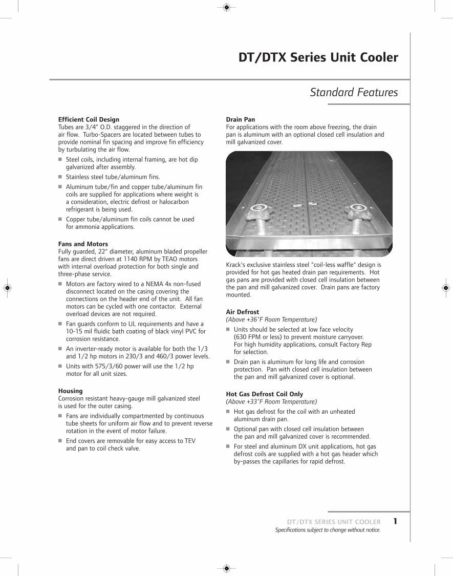
Krack's exclusive stainless steel "coil-less waffle" design isprovided for hot gas heated drain pan requirements. Hotgas pans are provided with closed cell insulation betweenthe pan and mill galvanized cover. Drain pans are factorymounted.
Air Defrost(Above +36˚F Room Temperature)n Units should be selected at low face velocity
(630 FPM or less) to prevent moisture carryover. For high humidity applications, consult Factory Rep for selection.
n Drain pan is aluminum for long life and corrosionprotection. Pan with closed cell insulation between the pan and mill galvanized cover is optional.
Hot Gas Defrost Coil Only(Above +33˚F Room Temperature)n Hot gas defrost for the coil with an unheated
aluminum drain pan.n Optional pan with closed cell insulation between
the pan and mill galvanized cover is recommended.n For steel and aluminum DX unit applications, hot gas
defrost coils are supplied with a hot gas header which by-passes the capillaries for rapid defrost.
Drain PanFor applications with the room above freezing, the drain pan is aluminum with an optional closed cell insulation andmill galvanized cover.
1DT/DTX SERIES UNIT COOLERSpecifications subject to change without notice.
DT/DTX SERIES UNIT COOLERSpecifications subject to change without notice.
2
DT/DTX Series Unit Cooler
Standard Features continued
Optional Features
Application
Hot Gas Defrost Unit(Below +32˚F Room Temperature)n The unique "waffle" (Krack exclusive) stainless steel
drain pan allows for the fastest hot gas defrost available.The design assures maximum pan heat in a minimumtime.
n Drain pan provided with closed cell insulation betweenthe pan and mill galvanized cover.
n The hot gas outlet connection of the drain pan isconnected to the coil with factory mounted interpipingincluding a check valve. The hot gas inlet connection has a gasket and flange shipped with the unit to connectwith the hot gas supply piping.
n For steel and aluminum DX unit applications, hot gasdefrost units are supplied with a hot gas header which by-passes the capillaries for rapid defrost.
Electric Defrostn Available models listed are limited to copper, aluminum,
and stainless steel tubes.n Tubular heaters are inserted through fin Turbo-Spacers
and efficiently defrost the coil from the inside out.n See Page 15 for heater kilowatts and amperage levels.
Water Defrostn Supply water temperature not to exceed 65˚F.n Drain pan is aluminum without insulation.n For six row units only.n See Page 17 for water flow rates required.
n Optional long throw adapters will provide a throw of 80-100 feet.
n Electric heat tape on the insulated drain pan cover.
n Hot gas, water, brine or electric reheat.n Stainless steel housing.
n The coil fully dipped and dried with a corrosion resistant coating on aluminum fins only.
n Two speed motor (1/2 hp, three phase only, can be used on any unit model).
n Inverter ready motor (1/2 hp, three phase only, can be used on any unit model).
Draw-Thru (DT/DTX) Unit Coolers can be used in mediumand low temperature holding coolers, freezers, shippingdocks, carcass chill, assembly and process areas.
Blow-Thru (BT/BTX) Unit Coolers should be used in roomsabove +20˚F only. BT units are not recommended for carcasschill applications. These unit coolers are not to be used forapplications requiring external static pressure by the fans.
Units should be located away from walls a distance equal to the unit height. Air discharge should be free of allobstructions. It is not necessary to locate units near walls of high palletized coolers or freezers. It is best to locate units so that an aisle is behind the unit to allow good return air circulation.
Thermostatic Expansion Valve (TEV)TEV for DXA must be externally equalized and the dischargetube removed, except for DT1 and DTX1 models using asingle circuit coil requiring a TEV with the discharge tube.
50 Hertz Application50 Hz applications result in a 17% reduction in fan motor speed. Fan pitch will be increased to compensate for 50 Hz derating. Unit capacity derate is not required.
Relative Sound RatingsConsult factory.

DT/DTX Series Unit Cooler
3DT/DTX SERIES UNIT COOLERSpecifications subject to change without notice.
Application continued
Fan Motor DataFan motor nameplate amps are total for the unit. Motorshave internal over-heat protection and are wired in paralleland cycled with one contactor.
n NEC limits total parallel motor ampacity to 15.0 amps at 600 volts and 20.0 amps at 125 volts or less. Highercapacity models for 115 or 208-230/1/60 service canbe provided when more than one parallel motor circuitis used.
n Ampacity will increase as room temperature is lowered (8% at 32˚F; 18% at -10˚F) due to the denser air. As the air temperature lowers TEAO motor capabilityincreases at a faster rate than the imposed fan load.
Coil ConnectionsAmmonia connection sizes shown in coil connection dataare adequate for the following design TD:
SaturatedSuction ˚F -40˚F -30˚F -20˚F +10˚F +20˚F
3 to 1
Recirculated 10 13 16 18 18
Direct Expansion – – – 15 18
Flooded 10 13 16 18 18
Consult factory for recirculated halocarbon, brine and heat reclaim inlet and outlet connections.n Halocarbon distributors will be brass with copper leads.n Aluminum tube coils will be furnished with a steel
companion flange kit, including the flange, bolts, nuts,isolation kits, and gaskets for the coil refrigerantconnections.
Capacity Correction Factors Tables:n SST = Saturated Suction Temperaturen Correction Factors valid for 3 and 4 fins/inchn Use 4 rows correction coefficients for 4/2 coils with reheat
3/4 ST STEEL/ALUM TUBE
3/4 STEEL/COPPER TUBE*
ROWS4 6 8
1.15 1.13 1.11
1.00 1.00 1.00
RECIRCULATED OR FLOODED FEED SST = +25˚F and Above
*R-22 or R-404A.
TABLE 1
SST ˚F
-50 to -40.1
-40 to -30.1
-30 to -20.1
-20 to +24.9
+25 and ABOVE
ROWS4 6 8
0.46 0.51 0.53
0.52 0.59 0.60
0.59 0.66 0.68
0.65 0.73 0.75
0.74 0.82 0.83
DX STEEL WITH R-22 OR R-404A
TABLE 2
SST ˚F
BELOW +24.9
+25 and ABOVE
ROWS4 6 8
0.67 0.74 0.76
0.76 0.83 0.84
DX STEEL WITH R-717
TABLE 4
SST ˚F
-50 to -40.1
-40 to -30.1
-30 to -20.1
-20 to +24.9
+25 and ABOVE
ROWS4 6 8
0.53 0.58 0.59
0.60 0.66 0.67
0.68 0.74 0.75
0.75 0.83 0.84
0.85 0.93 0.92
DX COPPER OR ALUMINUM WITH R-22 OR R-404A
TABLE 3
SST ˚F
BELOW +24.9
+25 and ABOVE
ROWS4 6 8
0.77 0.84 0.84
0.87 0.94 0.93
DX ALUMINUM WITH R-717
TABLE 5
TABLE NOTES:Capacities calculated for the following conditions:1. DX Frosted: Refrigerant R-717, SST -20˚F to +24.9˚F.
Apply low temperature correction factors below -20˚F.2. DX Wet: Refrigerant R-717, SST +25˚F to +40˚F.3. Recirculated or Flooded Frosted: Refrigerant R-717,
SST -50˚F to +24.9˚F.4. Recirculated or Flooded Wet: Refrigerant R-717,
SST +25˚F to +40˚F.
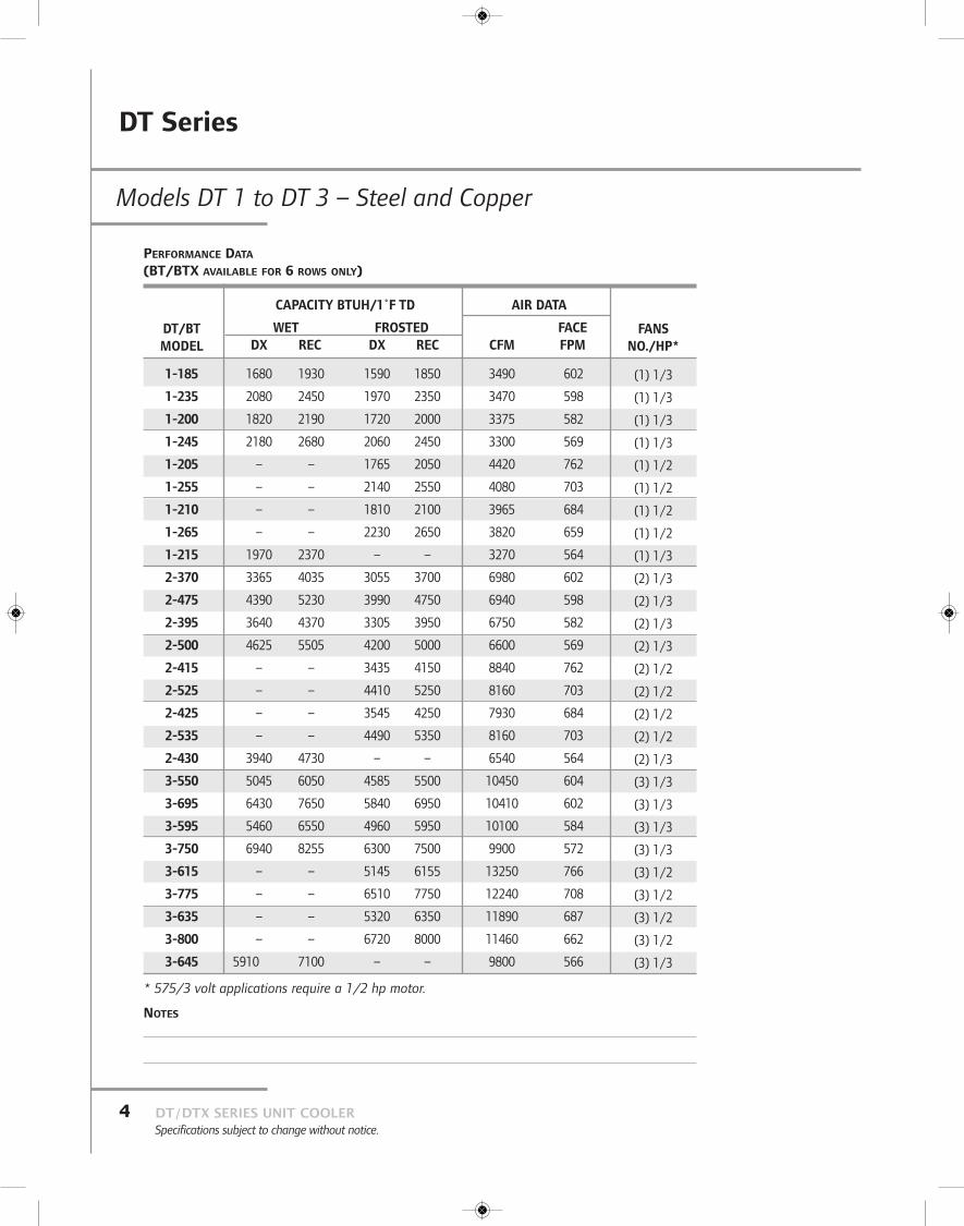
Models DT 1 to DT!3 – Steel and Copper
DT Series
DT/DTX SERIES UNIT COOLERSpecifications subject to change without notice.
4
DT/BTMODEL
1-185
1-235
1-200
1-245
1-205
1-255
1-210
1-265
1-215
2-370
2-475
2-395
2-500
2-415
2-525
2-425
2-535
2-430
3-550
3-695
3-595
3-750
3-615
3-775
3-635
3-800
3-645
CAPACITY BTUH/1˚F TD
WET FROSTEDDX REC DX REC
1680 1930 1590 1850
2080 2450 1970 2350
1820 2190 1720 2000
2180 2680 2060 2450
– – 1765 2050
– – 2140 2550
– – 1810 2100
– – 2230 2650
1970 2370 – –
3365 4035 3055 3700
4390 5230 3990 4750
3640 4370 3305 3950
4625 5505 4200 5000
– – 3435 4150
– – 4410 5250
– – 3545 4250
– – 4490 5350
3940 4730 – –
5045 6050 4585 5500
6430 7650 5840 6950
5460 6550 4960 5950
6940 8255 6300 7500
– – 5145 6155
– – 6510 7750
– – 5320 6350
– – 6720 8000
5910 7100 – –
AIR DATA
FACECFM FPM
3490 602
3470 598
3375 582
3300 569
4420 762
4080 703
3965 684
3820 659
3270 564
6980 602
6940 598
6750 582
6600 569
8840 762
8160 703
7930 684
8160 703
6540 564
10450 604
10410 602
10100 584
9900 572
13250 766
12240 708
11890 687
11460 662
9800 566
FANSNO./HP*
(1) 1/3
(1) 1/3
(1) 1/3
(1) 1/3
(1) 1/2
(1) 1/2
(1) 1/2
(1) 1/2
(1) 1/3
(2) 1/3
(2) 1/3
(2) 1/3
(2) 1/3
(2) 1/2
(2) 1/2
(2) 1/2
(2) 1/2
(2) 1/3
(3) 1/3
(3) 1/3
(3) 1/3
(3) 1/3
(3) 1/2
(3) 1/2
(3) 1/2
(3) 1/2
(3) 1/3
PERFORMANCE DATA
(BT/BTX AVAILABLE FOR 6 ROWS ONLY)
NOTES
* 575/3 volt applications require a 1/2 hp motor.

DT Series
Models DT 1 to DT!3 – Steel and Copper
5DT/DTX SERIES UNIT COOLERSpecifications subject to change without notice.
NOTES
DT/BTMODEL
1-185
1-235
1-200
1-245
1-205
1-255
1-210
1-265
1-215
2-370
2-475
2-395
2-500
2-415
2-525
2-425
2-535
2-430
3-550
3-695
3-595
3-750
3-615
3-775
3-635
3-800
3-645
COILFINS FACE SURFACE VOL.
ROWS INCH FT.2 FT.2 FT.2
6 3 5.8 377 0.7
8 3 5.8 501 0.9
6 4 5.8 482 0.7
8 4 5.8 641 0.9
6 3 5.8 377 0.7
8 3 5.8 501 0.9
6 4 5.8 482 0.7
8 4 5.8 641 0.9
6 6 5.8 693 0.7
6 3 11.6 754 1.2
8 3 11.6 1002 1.6
6 4 11.6 964 1.2
8 4 11.6 1282 1.6
6 3 11.6 754 1.2
8 3 11.6 1002 1.6
6 4 11.6 964 1.2
8 4 11.6 1282 1.6
6 6 11.6 1386 1.2
6 3 17.3 1131 1.8
8 3 17.3 1503 2.4
6 4 17.3 1446 1.8
8 4 17.3 1923 2.4
6 3 17.3 1131 1.8
8 3 17.3 1503 2.4
6 4 17.3 1446 1.8
8 4 17.3 1923 2.4
6 6 17.3 2079 1.8
APPROX. SHIPPING WEIGHT
STEEL COPPER
530 340
570 355
560 360
610 380
530 340
570 355
560 360
610 380
640 410
910 590
990 625
970 630
1070 670
910 590
990 625
970 630
1070 670
1130 730
1290 840
1400 890
1380 900
1530 960
1290 840
1400 890
1380 900
1530 960
1620 1050
PHYSICAL DATA
(BT/BTX AVAILABLE FOR 6 ROWS ONLY)
DT Series
DT/DTX SERIES UNIT COOLERSpecifications subject to change without notice.
6
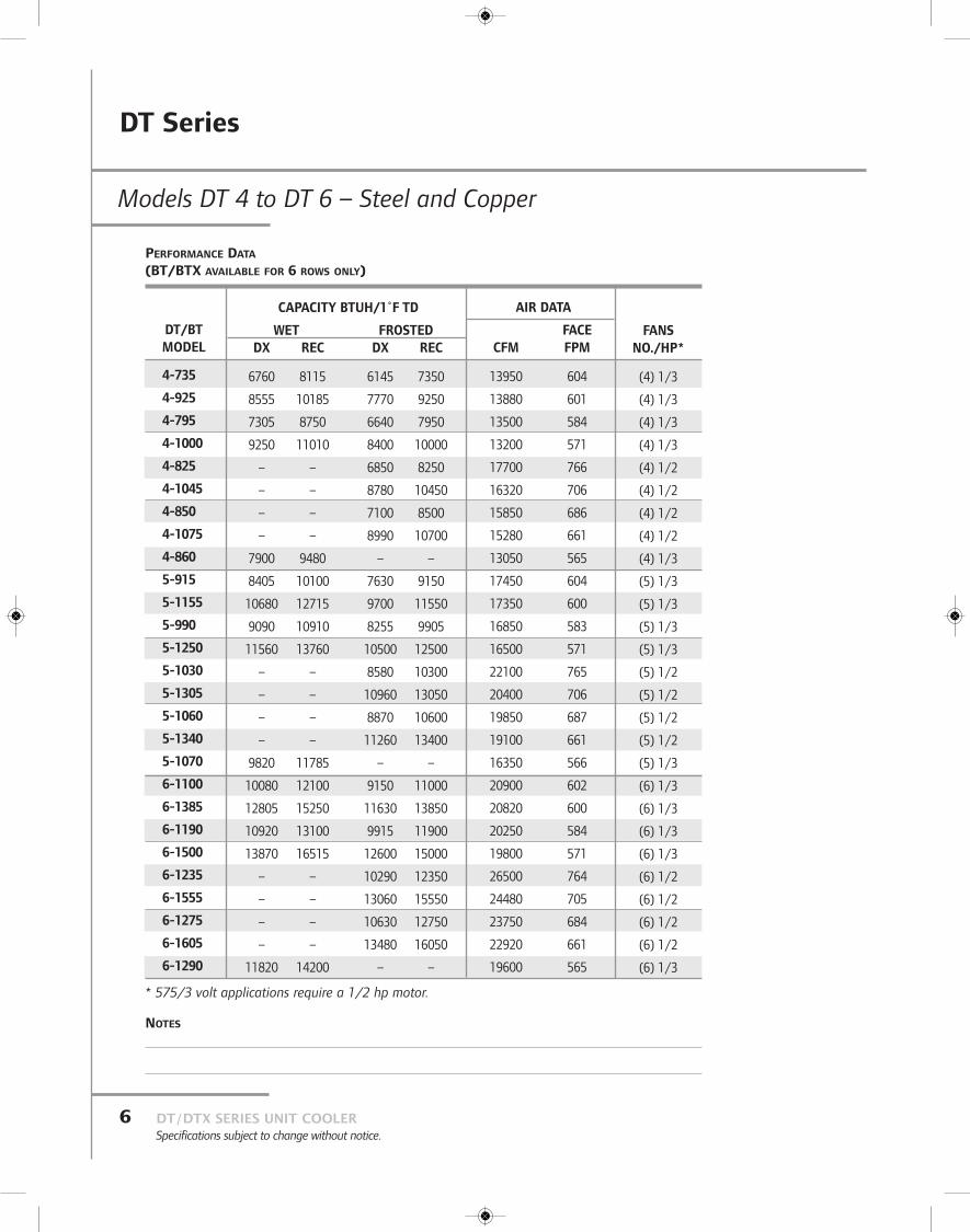
Models DT 4 to DT!6 – Steel and Copper
DT/BTMODEL
4-735
4-925
4-795
4-1000
4-825
4-1045
4-850
4-1075
4-860
5-915
5-1155
5-990
5-1250
5-1030
5-1305
5-1060
5-1340
5-1070
6-1100
6-1385
6-1190
6-1500
6-1235
6-1555
6-1275
6-1605
6-1290
CAPACITY BTUH/1˚F TD
WET FROSTEDDX REC DX REC
6760 8115 6145 7350
8555 10185 7770 9250
7305 8750 6640 7950
9250 11010 8400 10000
– – 6850 8250
– – 8780 10450
– – 7100 8500
– – 8990 10700
7900 9480 – –
8405 10100 7630 9150
10680 12715 9700 11550
9090 10910 8255 9905
11560 13760 10500 12500
– – 8580 10300
– – 10960 13050
– – 8870 10600
– – 11260 13400
9820 11785 – –
10080 12100 9150 11000
12805 15250 11630 13850
10920 13100 9915 11900
13870 16515 12600 15000
– – 10290 12350
– – 13060 15550
– – 10630 12750
– – 13480 16050
11820 14200 – –
AIR DATA
FACECFM FPM
13950 604
13880 601
13500 584
13200 571
17700 766
16320 706
15850 686
15280 661
13050 565
17450 604
17350 600
16850 583
16500 571
22100 765
20400 706
19850 687
19100 661
16350 566
20900 602
20820 600
20250 584
19800 571
26500 764
24480 705
23750 684
22920 661
19600 565
FANSNO./HP*
(4) 1/3
(4) 1/3
(4) 1/3
(4) 1/3
(4) 1/2
(4) 1/2
(4) 1/2
(4) 1/2
(4) 1/3
(5) 1/3
(5) 1/3
(5) 1/3
(5) 1/3
(5) 1/2
(5) 1/2
(5) 1/2
(5) 1/2
(5) 1/3
(6) 1/3
(6) 1/3
(6) 1/3
(6) 1/3
(6) 1/2
(6) 1/2
(6) 1/2
(6) 1/2
(6) 1/3
PERFORMANCE DATA
(BT/BTX AVAILABLE FOR 6 ROWS ONLY)
NOTES
* 575/3 volt applications require a 1/2 hp motor.

DT Series
7DT/DTX SERIES UNIT COOLERSpecifications subject to change without notice.
NOTES
Models DT 4 to DT!6 – Steel and Copper
DT/BTMODEL
4-735
4-925
4-795
4-1000
4-825
4-1045
4-850
4-1075
4-860
5-915
5-1155
5-990
5-1250
5-1030
5-1305
5-1060
5-1340
5-1070
6-1100
6-1385
6-1190
6-1500
6-1235
6-1555
6-1275
6-1605
6-1290
COILFINS FACE SURFACE VOL.
ROWS INCH FT.2 FT.2 FT.2
6 3 23.1 1508 2.3
8 3 23.1 2004 3.1
6 4 23.1 1928 2.3
8 4 23.1 2564 3.1
6 3 23.1 1508 2.3
8 3 23.1 2004 3.1
6 4 23.1 1928 2.3
8 4 23.1 2564 3.1
6 6 23.1 2772 2.3
6 3 28.9 1885 2.8
8 3 28.9 2505 3.7
6 4 28.9 3410 2.8
8 4 28.9 3205 3.7
6 3 28.9 1885 2.8
8 3 28.9 2505 3.7
6 4 28.9 3410 2.8
8 4 28.9 3205 3.7
6 6 28.9 3465 2.8
6 3 34.7 2262 3.4
8 3 34.7 3006 4.5
6 4 34.7 2892 3.4
8 4 34.7 3846 4.5
6 3 34.7 2262 3.4
8 3 34.7 3006 4.5
6 4 34.7 2892 3.4
8 4 34.7 3846 4.5
6 6 34.7 4158 3.4
APPROX. SHIPPING WEIGHT
STEEL COPPER
1670 1090
1820 1160
1790 1170
2000 1250
1670 1090
1820 1160
1790 1170
2000 1250
2110 1370
2050 1340
2230 1420
2200 1440
2450 1540
2050 1340
2230 1420
2200 1440
2450 1540
2600 1690
2430 1540
2650 1690
2610 1710
2910 1830
2430 1540
2650 1690
2610 1710
2910 1830
3090 2010
PHYSICAL DATA
(BT/BTX AVAILABLE FOR 6 ROWS ONLY)

DTX Series
DT/DTX SERIES UNIT COOLERSpecifications subject to change without notice.
8
Models DTX 1 to DTX 3 – Steel and Copper
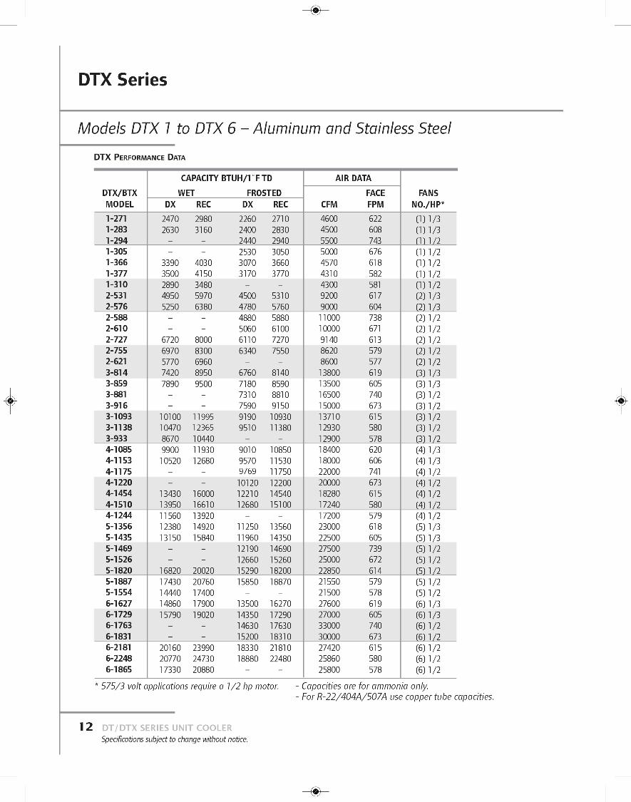
DTX/BTXMODEL1-2401-2501-2601-2701-3301-3401-2802-4702-5102-5202-5402-6552-6802-5603-7203-7603-7803-8103-9853-10253-840
CAPACITY BTUH/1˚F TDWET FROSTED
DX REC DX REC2190 2640 2000 24002330 2800 2120 2550
– – 2160 2600– – 2240 2700
3050 3630 2770 33003150 3740 2860 34002560 3080 – –4380 5280 3980 48004650 5650 4230 5100
– – 4320 5200– – 4480 5400
6050 7205 5500 65506280 7480 5710 68005110 6160 – –6570 7920 5980 72006980 8410 6350 7650
– – 6470 7800– – 6720 8100
9100 10835 8275 98509430 11220 8570 102007670 9240 – –
AIR DATAFACE
CFM FPM4600 6224500 6085500 7435000 6764570 6184310 5824300 5819200 6179000 60411000 73810000 6719140 6138620 5798600 57713800 61913500 60516500 74015000 67313710 61512930 58012900 578
FANSNO./HP*
(1) 1/3(1) 1/3(1) 1/2(1) 1/2(1) 1/2(1) 1/2(1) 1/2(2) 1/3(2) 1/3(2) 1/2(2) 1/2(2) 1/2(2) 1/2(2) 1/2(3) 1/3(3) 1/3(3) 1/2(3) 1/2(3) 1/2(3) 1/2(3) 1/2
PERFORMANCE DATA (BT/BTX AVAILABLE FOR 6 ROWS ONLY)
DTX/BTXMODEL1-2401-2501-2601-2701-3301-3401-2802-4702-5102-5202-5402-6552-6802-5603-7203-7603-7803-8103-9853-10253-840
COILFINS FACE SURFACE VOL.
ROWS INCH FT.2 FT.2 FT.2
6 3 7.4 485 0.96 4 7.4 620 0.96 3 7.4 485 0.96 4 7.4 620 0.98 3 7.4 645 1.28 4 7.4 825 1.26 6 7.4 890 0.96 3 14.9 970 1.56 4 14.9 1240 1.56 3 14.9 970 1.56 4 14.9 1240 1.58 3 14.9 1290 2.08 4 14.9 1650 2.06 6 14.9 1780 1.56 3 22.3 1455 2.36 4 22.3 1860 2.36 3 22.3 1455 2.36 4 22.3 1860 2.38 3 22.3 1935 3.18 4 22.3 2475 3.16 6 22.3 2670 2.3
APPROX.SHIPPING WEIGHT
STEEL COPPER660 425700 450660 425700 450720 455780 485800 5151140 7401210 7901140 7401210 7901260 8001370 8601410 9151610 10501720 11251610 10501720 11251790 11401960 12302030 1315
PHYSICAL DATA (BT/BTX AVAILABLE FOR 6 ROWS ONLY)
* 575/3 volt applications require a 1/2 hp motor.

DTX Series
9DT/DTX SERIES UNIT COOLERSpecifications subject to change without notice.
Models DTX 4 to DTX 6 – Steel and Copper
DTX/BTXMODEL4-9604-10204-10404-10804-13104-13604-11205-12005-12705-13005-13505-16405-17005-14006-14406-15306-15606-16206-19656-20256-1680
CAPACITY BTUH/1˚F TDWET FROSTED
DX REC DX REC8760 10560 7970 96009310 11220 8470 10200
– – 8630 10400– – 8960 10800
12100 14410 11000 1310012570 14960 11425 1360010230 12320 – –10960 13200 9960 1200011640 14020 10580 12750
– – 10790 13000– – 11200 13500
15150 18040 13775 1640015700 18700 14280 1700012780 15400 – –13150 15840 11950 1440013970 16830 12700 15300
– – 12950 15600– – 13450 16200
18160 21615 16510 1965018710 22275 17010 2025015340 18480 – –
AIR DATAFACE
CFM FPM18400 62018000 60622000 74120000 67318280 61517240 58017200 57923000 61822500 60527500 73925000 67222850 61421550 57921500 57827600 61927000 60533000 74030000 67327420 61525860 58025800 578
FANSNO./HP*
(4) 1/3(4) 1/3(4) 1/2(4) 1/2(4) 1/2(4) 1/2(4) 1/2(5) 1/3(5) 1/3(5) 1/2(5) 1/2(5) 1/2(5) 1/2(5) 1/2(6) 1/3(6) 1/3(6) 1/2(6) 1/2(6) 1/2(6) 1/2(6) 1/2
PERFORMANCE DATA (BT/BTX AVAILABLE FOR 6 ROWS ONLY)
DTX/BTXMODEL4-9604-10204-10404-10804-13104-13604-11205-12005-12705-13005-13505-16405-17005-14006-14406-15306-15606-16206-19656-20256-1680
COILFINS FACE SURFACE VOL.
ROWS INCH FT.2 FT.2 FT.2
6 3 29.7 1940 3.06 4 29.7 2480 3.06 3 29.7 1940 3.06 4 29.7 2480 3.08 3 29.7 2580 4.08 4 29.7 3300 4.06 6 29.7 3560 3.06 3 37.2 2425 3.66 4 37.2 3100 3.66 3 37.2 2425 3.66 4 37.2 3100 3.68 3 37.2 3225 4.88 4 37.2 4125 4.86 6 37.2 4450 3.66 3 44.6 2910 4.46 4 44.6 3720 4.46 3 44.6 2910 4.46 4 44.6 3720 4.48 3 44.6 3870 5.98 4 44.6 4950 5.96 6 44.6 5340 4.4
APPROX.SHIPPING WEIGHT
STEEL COPPER2090 13652240 14652090 13652240 14652330 14852560 16052640 17152560 16752750 18002560 16752750 18002860 18253150 19753250 21153040 19903260 21403040 19903260 21403400 21703740 23503860 2515
PHYSICAL DATA (BT/BTX AVAILABLE FOR 6 ROWS ONLY)
* 575/3 volt applications require a 1/2 hp motor.
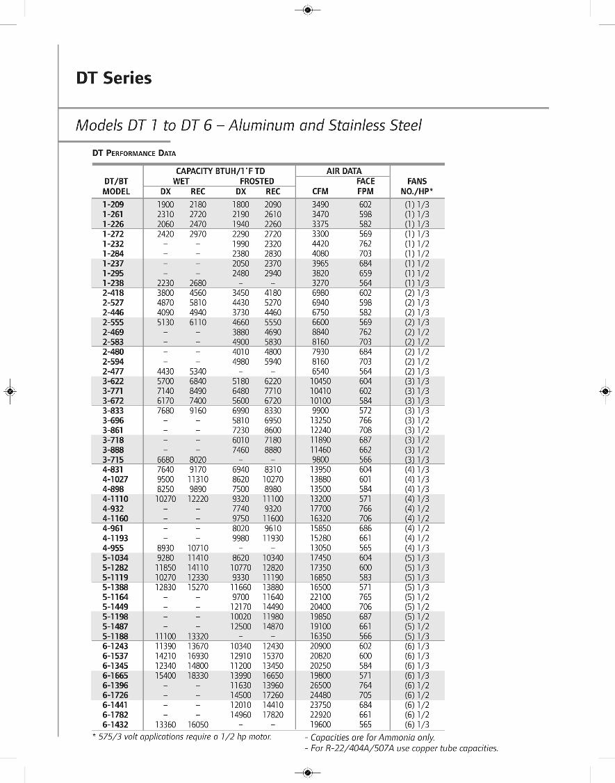

DT Series
Models DT 1 to DT 6 – Aluminum and Stainless Steel
DT/BTMODEL1-2091-2611-2261-2721-2321-2841-2371-2951-2382-4182-5272-4462-5552-4692-5832-4802-5942-4773-6223-7713-6723-8333-6963-8613-7183-8883-7154-8314-10274-8984-11104-9324-11604-9614-11934-9555-10345-12825-11195-13885-11645-14495-11985-14875-11886-12436-15376-13456-16656-13966-17266-14416-17826-1432
ROWS FPI6 38 36 48 46 38 36 48 46 66 38 36 48 46 38 36 48 46 66 38 36 48 46 38 36 48 46 66 38 36 48 46 38 36 48 46 66 38 36 48 46 38 36 48 46 66 38 36 48 46 38 36 48 46 6
FACE SURFACE COIL VOL.SQ. FT. SQ. FT. CU. FT.
5.8 377 0.75.8 501 0.95.8 482 0.75.8 641 0.95.8 377 0.75.8 501 0.95.8 482 0.75.8 641 0.95.8 693 0.711.6 754 1.211.6 1002 1.611.6 964 1.211.6 1282 1.611.6 754 1.211.6 1002 1.611.6 964 1.211.6 1282 1.611.6 1386 1.217.3 1131 1.817.3 1503 2.417.3 1446 1.817.3 1923 2.417.3 1131 1.817.3 1503 2.417.3 1446 1.817.3 1923 2.417.3 2079 1.823.1 1508 2.323.1 2004 3.123.1 1928 2.323.1 2564 3.123.1 1508 2.323.1 2004 3.123.1 1928 2.323.1 2564 3.123.1 2772 2.328.9 1885 2.828.9 2505 3.728.9 3410 2.828.9 3205 3.728.9 1885 2.828.9 2505 3.728.9 3410 2.828.9 3205 3.728.9 3465 2.834.7 2262 3.434.7 3006 4.534.7 2892 3.434.7 3846 4.534.7 2262 3.434.7 3006 4.534.7 2892 3.434.7 3846 4.534.7 4158 3.4
APPROX. SHIPPING WEIGHTALUMINUM ST. STEEL
295 340315 355320 360340 380295 340315 355320 360340 380360 410510 590545 625540 630590 670510 590545 625540 630590 670630 730720 840770 890770 900845 960720 840770 890770 900845 960900 1050930 10901000 11601000 11701100 1250930 10901000 11601000 11701100 12501175 13701145 13401230 14201225 14401350 15401145 13401230 14201225 14401350 15401450 16901355 15401460 16901455 17101600 18301355 15401460 16901455 17101600 18301720 2010
DT PHYSICAL DATA
* 575/3 volt applications require a 1/2 hp motor.
DTX Series
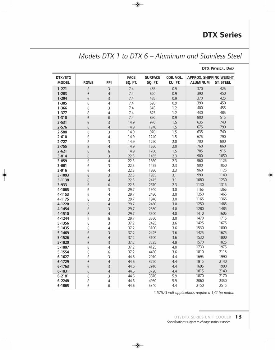
Models DTX 1 to DTX 6 – Aluminum and Stainless Steel
13DT/DTX SERIES UNIT COOLERSpecifications subject to change without notice.
DTX/BTXMODEL
1-2711-2831-2941-3051-3661-3771-3102-5312-5762-5882-6102-7272-7552-6213-8143-8593-8813-9163-10933-11383-9334-10854-11534-11754-12204-14544-15104-12445-13565-14355-14695-15265-18205-18875-15546-16276-17296-17636-18316-21816-22486-1865
ROWS FPI
6 36 46 36 48 38 46 66 36 46 36 48 38 46 66 36 46 36 48 38 46 66 36 46 36 48 38 46 66 36 46 36 48 38 46 66 36 46 36 48 38 46 6
FACE SURFACE COIL VOL.SQ. FT. SQ. FT. CU. FT.
7.4 485 0.97.4 620 0.97.4 485 0.97.4 620 0.97.4 645 1.27.4 825 1.27.4 890 0.914.9 970 1.514.9 1240 1.514.9 970 1.514.9 1240 1.514.9 1290 2.014.9 1650 2.014.9 1780 1.522.3 1455 2.322.3 1860 2.322.3 1455 2.322.3 1860 2.322.3 1935 3.122.3 2475 3.122.3 2670 2.329.7 1940 3.029.7 2480 3.029.7 1940 3.029.7 2480 3.029.7 2580 4.029.7 3300 4.029.7 3560 3.037.2 2425 3.637.2 3100 3.637.2 2425 3.637.2 3100 3.637.2 3225 4.837.2 4125 4.837.2 4450 3.644.6 2910 4.444.6 3720 4.444.6 2910 4.444.6 3720 4.444.6 3870 5.944.6 4950 5.944.6 5340 4.4
APPROX. SHIPPING WEIGHTALUMINUM ST. STEEL
370 425390 450370 425390 450400 455430 485800 515635 740675 790635 740675 790700 800760 860785 915900 1050960 1125900 1050960 1125990 11401080 12301130 13151165 13651250 14651165 13651250 14651280 14851410 16051470 17151425 16751530 18001425 16751530 18001570 18251730 19751810 21151695 19901815 21401695 19901815 21401870 21702060 23502150 2515
DTX PHYSICAL DATA
* 575/3 volt applications require a 1/2 hp motor.
DT/DTX Series
DT/DTX SERIES UNIT COOLERSpecifications subject to change without notice.
14
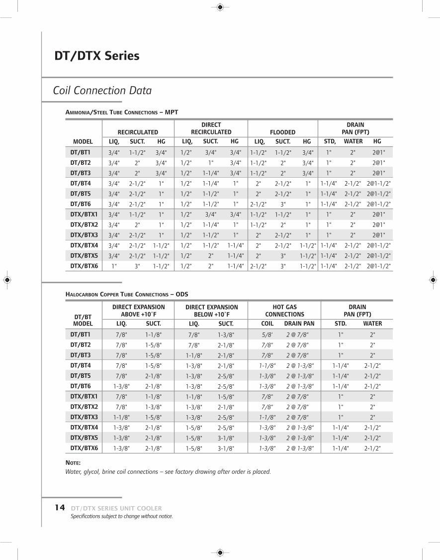
Coil Connection Data
MODEL
DT/BT1
DT/BT2
DT/BT3
DT/BT4
DT/BT5
DT/BT6
DTX/BTX1
DTX/BTX2
DTX/BTX3
DTX/BTX4
DTX/BTX5
DTX/BTX6
RECIRCULATEDLIQ, SUCT. HG
3/4" 1-1/2" 3/4"
3/4" 2" 3/4"
3/4" 2" 3/4"
3/4" 2-1/2" 1"
3/4" 2-1/2" 1"
3/4" 2-1/2" 1"
3/4" 1-1/2" 1"
3/4" 2" 1"
3/4" 2-1/2" 1"
3/4" 2-1/2" 1-1/2"
3/4" 2-1/2" 1-1/2"
1" 3" 1-1/2"
DIRECTRECIRCULATED
LIQ, SUCT. HG
1/2" 3/4" 3/4"
1/2" 1" 3/4"
1/2" 1-1/4" 3/4"
1/2" 1-1/4" 1"
1/2" 1-1/2" 1"
1/2" 1-1/2" 1"
1/2" 3/4" 3/4"
1/2" 1-1/4" 1"
1/2" 1-1/2" 1"
1/2" 1-1/2" 1-1/4"
1/2" 2" 1-1/4"
1/2" 2" 1-1/4"
DRAINPAN (FPT)
STD, WATER HG
1" 2" 2@1"
1" 2" 2@1"
1" 2" 2@1"
1-1/4" 2-1/2" 2@1-1/2"
1-1/4" 2-1/2" 2@1-1/2"
1-1/4" 2-1/2" 2@1-1/2"
1" 2" 2@1"
1" 2" 2@1"
1" 2" 2@1"
1-1/4" 2-1/2" 2@1-1/2"
1-1/4" 2-1/2" 2@1-1/2"
1-1/4" 2-1/2" 2@1-1/2"
FLOODEDLIQ, SUCT. HG
1-1/2" 1-1/2" 3/4"
1-1/2" 2" 3/4"
1-1/2" 2" 3/4"
2" 2-1/2" 1"
2" 2-1/2" 1"
2-1/2" 3" 1"
1-1/2" 1-1/2" 1"
1-1/2" 2" 1"
2" 2-1/2" 1"
2" 2-1/2" 1-1/2"
2" 3" 1-1/2"
2-1/2" 3" 1-1/2"
AMMONIA/STEEL TUBE CONNECTIONS – MPT
DT/BTMODEL
DT/BT1
DT/BT2
DT/BT3
DT/BT4
DT/BT5
DT/BT6
DTX/BTX1
DTX/BTX2
DTX/BTX3
DTX/BTX4
DTX/BTX5
DTX/BTX6
DIRECT EXPANSIONABOVE +10˚F
LIQ. SUCT.
7/8" 1-1/8"
7/8" 1-5/8"
7/8" 1-5/8"
7/8" 1-5/8"
7/8" 2-1/8"
1-3/8" 2-1/8"
7/8" 1-1/8"
7/8" 1-3/8"
1-1/8" 1-5/8"
1-3/8" 2-1/8"
1-3/8" 2-1/8"
1-3/8" 2-1/8"
DIRECT EXPANSIONBELOW +10˚F
LIQ. SUCT.
7/8" 1-3/8"
7/8" 2-1/8"
1-1/8" 2-1/8"
1-3/8" 2-1/8"
1-3/8" 2-5/8"
1-3/8" 2-5/8"
1-1/8" 1-5/8"
1-3/8" 2-1/8"
1-3/8" 2-5/8"
1-5/8" 2-5/8"
1-5/8" 3-1/8"
1-5/8" 3-1/8"
DRAINPAN (FPT)
STD. WATER
1" 2"
1" 2"
1" 2"
1-1/4" 2-1/2"
1-1/4" 2-1/2"
1-1/4" 2-1/2"
1" 2"
1" 2"
1" 2"
1-1/4" 2-1/2"
1-1/4" 2-1/2"
1-1/4" 2-1/2"
HOT GASCONNECTIONS
COIL DRAIN PAN
5/8' 2 @ 7/8"
7/8" 2 @ 7/8"
7/8" 2 @ 7/8"
1-1/8" 2 @ 1-3/8"
1-3/8" 2 @ 1-3/8"
1-3/8" 2 @ 1-3/8"
7/8" 2 @ 7/8"
7/8" 2 @ 7/8"
1-1/8" 2 @ 7/8"
1-3/8" 2 @ 1-3/8"
1-3/8" 2 @ 1-3/8"
1-3/8" 2 @ 1-3/8"
HALOCARBON COPPER TUBE CONNECTIONS – ODS
NOTE:Water, glycol, brine coil connections – see factory drawing after order is placed.

DT/DTX Series
15DT/DTX SERIES UNIT COOLERSpecifications subject to change without notice.
Electric Defrost Data
UNIT
DT/BT 1DT 1
DT/BT 2DT 2
DT/BT 3DT 3
DT/BT 4DT 4
DT/BT 5
DT 5
DT/BT 6DT 6
DTX/BTX 1DTX 1
DTX/BTX 2DTX 2
DTX/BTX 3
DTX 3
DTX/BTX 4DTX 4
DTX/BTX 5
DTX 5
DTX/BTX 6
DTX 6
NO. OF TOTAL NO. OF CIRCUITS – TOTAL CIRCUITS – AMPSHTRS AMPS PER CIRCUIT HTRS PER CIRCUIT
KW 230V/3 460V/3 575V/3 KW 380V/3
3.0 1 x 7.5 1 x 3.8 1 x 3.0 2.7 1 x 4.1
4.5 1 x 11.3 1 x 5.6 1 x 4.5 4.1 1 x 6.26.0 1 x 15.1 1 x 7.5 1 x 6.0 5.5 1 x 8.39.0 1 x 22.6 1 x 11.3 1 x 9.0 8.2 1 x 12.4
9.0 1 x 22.6 1 x 11.3 1 x 9.0 8.2 1 x 12.413.5 1 x 33.9 1 x 16.9 1 x 13.6 12.3 1 x 18.7
12.0 1 x 30.1 1 x 15.1 1 x 12.0 10.9 1 x 16.6
18.0 1 x 45.2 1 x 22.6 1 x 18.1 16.4 1 x 24.9
15.0 1 x 37.7 1 x 18.8 1 x 15.1 13.6 1 x 20.7
22.5 1 x 33.9 1 x 28.2 1 x 22.6 20.5 1 x 31.1
1 x 22.6
18.0 1 x 45.2 1 x 22.6 1 x 18.1 16.4 1 x 24.9
27.0 2 x 33.9 1 x 33.9 1 x 27.1 24.6 1 x 37.3
4.5 1 x 11.3 1 x 5.6 1 x 4.5 4.1 1 x 6.2
6.0 1 x 15.1 1 x 7.5 1 x 6.0 5.5 1 x 8.3
9.0 1 x 22.6 1 x 11.3 1 x 9.0 8.2 1 x 12.4
12.0 1 x 30.1 1 x 15.1 1 x 12.0 10.9 1 x 16.613.5 1 x 33.9 1 x 16.9 1 x 13.6 12.3 1 x 18.7
18.0 1 x 45.2 1 x 22.6 1 x 18.1 16.4 1 x 24.9
18.0 1 x 45.2 1 x 22.6 1 x 18.1 16.4 1 x 24.924.0 2 x 30.1 1 x 30.1 1 x 24.1 21.8 1 x 33.2
22.5 1 x 33.9 1 x 28.2 1 x 22.6 20.5 1 x 31.11 x 22.6
30.0 1 x 45.2 1 x 37.7 1 x 30.1 27.3 1 x 41.5
1 x 30.1
27.0 2 x 33.9 1 x 33.9 1 x 27.1 24.6 1 x 37.3
36.0 2 x 45.2 1 x 45.2 1 x 36.1 32.8 1 x 24.9
NO. OF TOTAL NO. OF CIRCUITS – TOTAL CIRCUITS - AMPSHTRS AMPS PER CIRCUIT HTRS PER CIRCUIT
KW 230V/3 460V/3 575V/3 KW 380V/3
5.4 1 x 13.6 1 x 6.8 1 x 5.4 4.9 1 x 7.56.9 1 x 17.3 1 x 8.7 1 x 6.9 6.3 1 x 9.510.4 1 x 26.2 1 x 13.1 1 x 10.5 9.5 1 x 14.4
13.4 1 x 33.7 1 x 16.9 1 x 13.5 12.2 1 x 18.615.4 1 x 38.8 1 x 19.4 1 x 15.5 14.1 1 x 21.4
19.9 1 x 33.9 1 x 25.0 1 x 20.0 18.1 1 x 27.61 x 16.2
20.5 2 x 25.7 1 x 25.7 1 x 20.5 18.6 1 x 28.3
26.5 2 x 33.2 1 x 33.2 1 x 26.6 24.1 1 x 36.625.5 1 x 37.6 1 x 32.0 1 x 25.6 23.2 1 x 35.2
1 x 26.3
33.0 2 x 33.9 1 x 41.4 1 x 33.1 30.0 1 x 45.6
1 x 15.0
30.5 2 x 38.3 1 x 38.3 1 x 30.6 27.8 1 x 42.239.5 2 x 33.9 2 x 24.8 1 x 39.7 35.9 2 x 27.3
1 x 31.4
6.9 1 x 17.3 1 x 8.7 1 x 6.9 6.3 1 x 9.5
8.4 1 x 21.1 1 x 10.5 1 x 8.4 7.6 1 x 11.6
13.4 1 x 33.7 1 x 16.7 1 x 13.5 12.2 1 x 18.616.4 1 x 41.2 1 x 20.6 1 x 16.5 14.9 1 x 22.719.9 1 x 33.9 1 x 25.0 1 x 20.0 18.1 1 x 27.6
1 x 16.2
24.4 1 x 33.9 1 x 30.7 1 x 24.5 22.2 1 x 33.81 x 27.5
26.5 2 x 33.2 1 x 33.2 1 x 26.6 24.1 1 x 36.632.5 2 x 40.7 1 x 40.7 1 x 32.6 29.5 1 x 44.9
33.0 2 x 33.9 1 x 41.4 1 x 33.1 30.0 1 x 45.6
1 x 15.140.5 1 x 33.9 1 x 30.1 1 x 40.7 36.8 1 x 33.2
1 x 26.3 1 x 20.7 1 x 22.81 x 41.4
39.5 2 x 33.9 2 x 24.8 1 x 39.7 35.9 2 x 27.3
1 x 31.448.5 2 x 45.2 2 x 30.4 2 x 24.4 44.1 2 x 33.5
1 @ 31.4
ROWS
6
868
68
6
8
6
8
6
8
6
8
6
86
8
686
8
6
8
ED EDL
DT/DTX Series
DT/DTX SERIES UNIT COOLERSpecifications subject to change without notice.
16
CoilsDT/DTX, BT/BTX Series propeller fan units are modular in design in one through six fans with two overall heights.Units are designed for medium and freezer temperaturesabove -40˚F suction in capacities from 2 to 20 nominal tons.Maximum heat transfer is achieved by staggering 3/4" O.D. tubes in the direction of air flow. Circuits are cross fedwith vertical headers resulting in equal circuit loading forhorizontal air flow coils. Coils are 6 and 8 rows deep with 3, 4 or 6 fins/inch, fin spacing achieved by Turbo-Spacers.Coils are constructed and listed in accordance withUnderwriters Laboratories Standards. Each coil is testedunderwater with 350 psig air, with all steel coils being tested before and after galvanizing.
Material of Constructionn Hot dipped galvanized steel tube and fins.n Aluminum tube and fins. Aluminum coils are provided
with steel companion flanges with bolts, nuts, isolationkits and gaskets, for refrigeration connections.
n Copper tube with aluminum fins. Optional copper fin is available.
n Stainless steel tubes and aluminum fins.
Rating DataEach coil is engineered for maximum efficiency for its specific design application.n Ratings are based on sensible heat removal.
Capacity listed is BTUH/˚F TD sensible heat removal with the coil wet, dry or frosted. Ratings are valid forTDs 20˚F or less. Wet coil heat transfer is more efficientthan frosted resulting in higher ratings.
n Wet coil applications are for room temperatures above32˚F. Selections should be limited to 630 FPM to prevent moisture carryover.
n Consult a Sales Rep for high humidity conditions forproper air velocity.
Fan Motor HeatMotor heat is not included in the ratings and is usuallyincluded in the load estimate.
Coolers 4,000 BTUH/HPFreezers 4,400 BTUH/HP
Temperature Difference (TD)Temperature difference (TD) is the difference between return air temperature or room air and coil saturated refrigerant temperature. Rated capacity is multiplied by the TD to determine total sensible heat capacity in BTUH.
Refrigerant FeedsRecirculated coils have graduated liquid feed orifices to balance static head and reduce hot gas blow-by during defrost. Units operating with an overfeed system must provide liquid at 5 psi above saturated suction pressure and the liquid temperature within 10˚F to 30˚F of saturated suctiontemperature depending on the suction temperature. Liquid feed temperature and pressure must be specified to assureproper coil design. Consult factory for recirculated lowtemperature R-22 applications.n RT – Recirculated top feed is recommended for air, water,
or electric defrost. Refrigerant oil flows downhill to thesuction header. This application is not recommended forhot gas defrost units.
n RB – Recirculated bottom feed is recommended for hot gasdefrost applications or very high TDs. Hot gas condensateand oil flow downhill, back-flowing through the liquid feedorifices which restrict gas blow-by. Condensate is relievedthrough the liquid header. Defrost condensate reliefdevices must be located below the liquid connection. Floatdrainer should be used in series piped units only (standardconfiguration); unrelieved vapor will prevent complete andproper defrost cycles.
n DX – Direct expansion coils are circuited to have a minimum pressure drop and maintain refrigerant velocity for oil return. Direct expansion coils employ distributorsand capillaries to feed each circuit. TEVs must be externallyequalized and, on ammonia applications, the dischargetubes must be removed. If a unit does not have adistributor, do not remove the TEV discharge tube.Ammonia TEV applications are not recommended forsuction temperatures below 0˚F or with TD selections lessthan 12˚F. If sub-cooled liquid is used, it must be specified to assure proper coil circuiting.
n FL – Flooded coils are circuited to minimize internal losseswhile maintaining minimum surge drum operating level.When closed coupled, the liquid level in the drum should be four inches or more above the coil. Flooded coil ratingsare the same as recirculated ratings.
n B,C – Coils can be circuited for water or brine (single-phase) refrigerants. Factory engineering is required forproper unit selection. Provide required capacity, brine type,brine concentration, room temperature, entering brinetemperature and GPM for selection.
Engineering Data

DT/DTX Series
17DT/DTX SERIES UNIT COOLERSpecifications subject to change without notice.
Reheatn Hot Gas/Brine/Water Reheat:
- When used with a six row coil, the cooling coil is the first four rows and the reheat is the last two rows.Contact factory for cooling capacity.
- When used with an eight row coil, the cooling coil is the first six rows and the reheat is the last two rows.The cooling capacity is similar to astandard six row coil with a similar face velocity.
- Eight total row units can be DT/DTXonly. Six total row units can beDT/DTX or BT/BTX.
n Electric Reheat:- A heater assembly is mounted between
the coil face and the fan.
- Assembly includes a built in overheatthermostat.
- One 4.65 kw heater per fan section.- Heater is factory wired to a terminal
block on the header end casing.
- Can only be used with six row DT/DTX units.
Drain Pan Cover Heatingn In rooms that cannot have humidity
condensate dripping from the drain pancover, a heat tape is available to warmthe cover.
n The electric heat tape is affixed to theinside of the pan cover with the tail outthe side of the pan.
n 115/1 and 230/1 voltages.n Amp draw shown on unit drawings
when ordered.
Engineering Data
Fan Motor Data – DT/DTX, BT/BTX
Fan Motor Nameplate Total Full Load AMPS
208/1 208/3Fan No. HP 115/1 230/1 230/3 460/3 380/3 575/3
1 1/3 5.40 2.70 1.70 0.85 0.55 -1 1/2 7.80 3.90 2.00 1.00 1.10 0.762 1/3 10.80 5.40 3.40 1.70 1.10 -
2 1/2 15.60 7.80 4.00 2.00 2.20 1.523 1/3 16.20 8.10 5.10 2.55 1.65 -
3 1/2 – 11.70 6.00 3.00 3.30 2.284 1/3 – 10.80 6.80 3.40 2.20 -
4 1/2 – – 8.00 4.00 4.40 3.04
5 1/3 – 13.50 8.50 4.25 2.75 -5 1/2 – – 10.00 5.00 5.50 3.80
6 1/3 – – 10.20 5.10 3.30 -
6 1/2 – – 12.00 6.00 6.60 4.56
Reheat Heater Total Full Load AMPS
Heater 208/3Quantity KW 230/3 460/3 380/3 575/3
1 4.65 11.67 5.84 7.06 4.67
2 9.30 23.35 11.67 14.13 9.34
3 13.95 35.02 17.51 21.19 14.014 18.60 46.69 23.35 28.26 18.685 23.25 58.36 29.18 35.32 23.35
6 27.90 70.04 35.02 42.39 28.01
DT/DTX Water Defrost Data (6-Row Units)Water defrost must be arranged so that all water pipes are free drainingafter a defrost cycle in rooms below +32˚F. Water flow requirements using65˚F water for draw-thru or blow-thru are as follows:
Water Defrost
No. Fans GPM Connections No./Size (FPT)
1 8 1 / 1"2 15 1 / 1"3 23 1 / 1"
4 32 2 / 1"5 39 2 / 1"
6 48 2 / 1"
DT/DTX Series
DT/DTX SERIES UNIT COOLERSpecifications subject to change without notice.
18
Ordering Information
When Ordering, Please Specify:n Quantity and complete model numbern SST-Saturated Suction Temperaturen Room temperaturen Fan motor voltagen Heater voltage (if applies)n Control voltagen Options and accessoriesn Sub-cooled liquid-DXF feedsn Number of drawings for approval – Not released for manufacturen Manufacture commences with order approval
Krack reserves the right to change or revise
specifications and product design in connection with
any feature of our products.
Such changes do not entitle the buyer to
corresponding changes, improvements, additions or replacements
for equipment previously sold or shipped.

DT/DTX SERIES UNIT COOLERSpecifications subject to change without notice.

SGS Refrigeration, Inc. 827 W. Progress Drive Dixon, IL 61021Ph: 815.284.2700
sgsrefrigeration.com
Printed in U.S.A. ©2013 SGS Refrigeration Inc. DT/DTX_K_082012