Embed Size (px)
Citation preview
DTG
Digital Test Generator
SoundPals
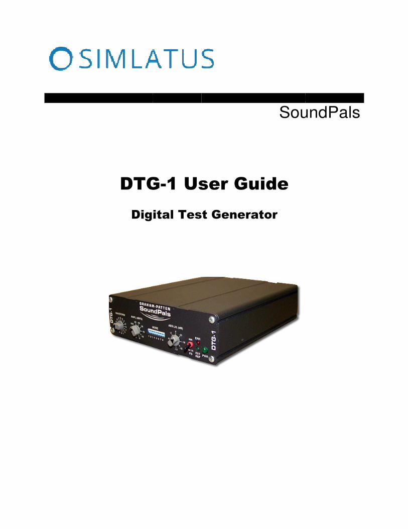
DTG-1 User Guide
Digital Test Generator
SoundPals

Printing History SoundPals™ DTG-1 Digital Test Generator
Rev. N/C
SEPTEMBER 2016
Printed in U.S.A.
Part Number 08-2027-00
The information contained in this guide is subject to change without notice or obligation.
Copyrights and Trademarks © 2015
Contents of this publication may not be reproduced in any form without the written permission of Simlatus Corporation. Reproduction or reverse engineering of copyrighted software is prohibited.
FCC Compliance This equipment has been tested and found to comply with the limits for a Class A digital device pursuant to Part 15 of the FCC Rules. These limits are designed to provide reasonable protection against harmful interference when the equipment is operated in a commercial environment. This equipment generates, uses, and can radiate radio frequency energy and, if not installed and used in accordance with the instruction manual, may cause harmful interference to radio communications. Operation of this equipment in a residential area is likely to cause harmful interference in which case the user will be required to correct the interference at your own expense.
Warranty Statement Simlatus Corporation warrants that the equipment it manufactures is free from defects in workmanship and materials and meets applicable published specifications. Equipment that has been operated within published ratings and has not been subjected to abuse or modification, and which fails because of such defects, will be replaced or repaired at the Company’s discretion if it is returned, freight prepaid, to Simlatus within three years of receipt.
This warranty supersedes all other Warranties, express or implied. Simlatus Corporation is not liable for any consequential damages.
Company Address
Simlatus Corporation
175 Joerschke Drive Suite A Grass Valley, CA 95945 530-205-3437 [email protected]

Table of Contents
ii • Table of Contents DTG-1 User Guide
Table of Contents ii
Introduction 1
What are SoundPals? .............................................................................................................. 1Documentation Conventions .................................................................................................... 1Signals and Values .................................................................................................................. 1Warnings .................................................................................................................................. 1Unpacking and Inspection ....................................................................................................... 2Power Supply Note .................................................................................................................. 2
DTG-1 3
About the DTG-1 ...................................................................................................................... 3DTG Applications ..................................................................................................................... 5DTG Function Label ................................................................................................................. 5DTG-1 Installation .................................................................................................................... 7
Connecting Power ............................................................................................................. 7Connecting AES/Word Clock Reference Input ................................................................. 7Connecting AES Waveform Output ................................................................................... 7
DTG-1 Operation ..................................................................................................................... 8Using the Waveform Switch .............................................................................................. 8Using the Amplitude Switch .............................................................................................. 9Using the AES Level Switch ............................................................................................ 10Using the Mode DIP Switch ............................................................................................ 11
Consumer Mode .................................................................................................................... 11Professional Mode ................................................................................................................. 12Recommended Default Settings ............................................................................................ 13
Consumer Mode Settings ............................................................................................... 13Professional Mode Defaults ............................................................................................ 13
DTG-1 Interconnection .......................................................................................................... 14Generating Test Waveforms or "Leader" Tones ............................................................. 14DAT Performance and Copy Protection Tests ................................................................ 14DTG-1 Signal Distribution ............................................................................................... 15
Internal Jumpers .................................................................................................................... 16DTG-1 Troubleshooting ......................................................................................................... 17
Error Conditions .............................................................................................................. 17DTG-1 Specifications ............................................................................................................. 18
Audio Specifications ........................................................................................................ 18Environmental Specifications and Dimensions ............................................................... 19
Inside the Module ........................................................................................... 20
In This Section ....................................................................................................................... 20Before You Begin ................................................................................................................... 20Opening the Module .............................................................................................................. 20Closing the Module ................................................................................................................ 20
External Power ................................................................................................ 21
About Power Supplies ........................................................................................................... 21CE Compliance ...................................................................................................................... 21Portable Power Sources ........................................................................................................ 21Power Supply Specifications ................................................................................................. 21

Introduction
DTG-1 User Guide Page 1
What are SoundPals?
Each Simlatus Corporation SoundPals module is essentially a digital audio building block that can be used independently, or interconnected to perform more advanced mixing and audio processing functions.
SoundPals can be used in both standalone and system configurations:
• In a “standalone” configuration, each SoundPals module is designed to perform a specific audio processing function such as digital-to-Analog conversion. In this way, each module functions as a perfect low-cost adjunct to larger mixing consoles (such as the Graham-Patten D/ESAM series) — for single-purpose processing tasks.
• In a “system” configuration, SoundPals can be linked to form more comprehensive digital audio tools. For field recording, studio applications, and workstation applications, SoundPals can be used to seamlessly perform functions that would otherwise require extensive peripheral gear. Best of all, SoundPals “systems” can be re-configured quickly and easily — to suit your changing audio production requirements.
All SoundPals modules are extremely compact, rugged, and identical in size for ease of installation, interconnection, and use. In addition, SoundPals support AES3id. This allows longer, more robust AES signal distribution using standard coaxial cable. Error free distances of 1000 feet can be attained using inexpensive coaxial cables.
Documentation Conventions
The following documentation conventions are used in this guide:
• Buttons, knobs, connectors, and switches are indicated in bold-faced capital letters. For example:
Adjust the left GAIN TRIM to …
• Primary sections are listed in bold text, with a line above:
Primary Section
• Secondary sections are listed in bold text, with no line: Secondary Section
Signals and Values
Note the following important information regarding audio signal level:
• AES3 = Balanced output with 2 channels of digital audio (left and right) • AES3id = Unbalanced output with 2 channels of digital audio (left and right) • Word Clock = 5V p-p square wave at the sampling frequency (32 KHz – 50 KHz). One edge of the square wave is used as the sampling reference.

DTG-1 User Guide Page 2
Warnings
Please observe the following important warnings:
• Heed all warnings on the unit and in the instructions. • Do not use this product in or near water. • Route power cords and other cables so that they are not likely to be damaged.
Disconnect power before cleaning. Do not use liquid or aerosol cleaners; use only a damp cloth.
Unpacking and Inspection
When you receive your SoundPals modules, inspect the cartons for signs of damage. Contact your dealer and the shipper immediately if you suspect any damage has occurred during shipping. Check the contents of each box to be sure that all parts are included. If any items are missing, contact your dealer immediately.
Power Supply Note
SoundPals are delivered with a power connector only. A separate power supply must be obtained. Simlatus Corporation offers several power solutions for both domestic and international customers. Refer to “External Power” for detailed power specifications for users who wish to configure their own power source, rather than purchase one from Simlatus.

DTG-1
DTG-1 User Guide Page 3
Product Description
The Simlatus Corporation SoundPals DTG-1 is a Digital Test Generator that produces a variety of AES test signal waveforms with adjustable frequency and amplitude. The DTG allows you to vary the AES output level and also set different combinations of channel status bits. The unit’s sampling frequency can be generated internally at 48 KHz or 44.1 KHz, or it can be locked to an external AES3id (or Word Clock) reference.
The unit offers the following features:
• AES and AES3id waveform outputs • 16-position rotary waveform switch • 10-position rotary amplitude switch • 8-position rotary level switch • 8-position DIP Switch for mode and status bit settings:
~ Consumer mode settings are provided for Emphasis, Copy Protection, Generation and Dither.
~ Professional mode settings are provided for Emphasis, Audio Mode, Resolution and Dither.
~ All DIP Switch functions listed on top chassis label.
• AES or Word Clock reference input • Switch-selectable internal reference, 44.1 KHz or 48 KHz • Optional rack mounting tray (1 RU) • Compact size, rugged construction • AES or Word Clock reference
Note that the DTG-1 can synchronize to an external AES reference or Word Clock at 32 KHz-50 KHz sampling rate. When an external reference is not provided, the unit runs at the default frequency, as set by the front panel switch.
The figure below illustrates the DTG-1’s front panel:
DT
G-1
DT
G-1
PWR
ERR
51
EXTREF
OFFWAVEFORM
R ABP
CN
DM
ELFK
GJ H
AMPL (dBFS)
0ST
SW
MIN
-60-20
-18
-10
-9
-1
1 2 3 4 5 6 7 8
MODE
AES LVL (dB)
0
-12-9
-6
-3 -21
-18
-15
48K
44.1KFS
2 3 4 7
6 8
1) Waveform Switch — the 16-position rotary Waveform Switch selects the output waveform type. For quick reference, all waveforms are listed on the DTG Function Label on top of the chassis. Refer to the “Using the Waveform Switch” section for details.
2) Amplitude Switch — the 10-position rotary Amplitude Switch allows you to select the amplitude of the output waveform. Each position (with the exception of ST, SW, and MIN) is marked with amplitude in dBFS. Refer to the “Using the Amplitude Switch” section for details.

DTG-1 User Guide Page 4
3) Mode DIP Switch — the 8-position Mode DIP Switch allows you to set both consumer and professional settings for functions such as Emphasis, Copy Protection, Generation, Audio Mode, Resolution and Dither. For quick reference, all switch modes are listed on the DTG Function Label on top of the chassis. Refer to the “Using the Mode DIP Switch” section for details.
4) AES Level Switch — the 8-position rotary AES Level Switch selects the AES3 and AES3id output amplitudes. The total range is 0 (zero) to -21 dB. Each position is marked with amplitude in dB, relative to both AES standards:
• 4.5 V p-p for AES3 • 1 V p-p for AES3id
5) Sample Frequency Switch — the two-position toggle switch selects sampling frequencies of 48 KHz or 44.1 KHz. The switch is active only when no external reference is present.
6) ERR — the red Error LED, when lit, indicates a waveform error. Refer to the “Error Conditions” section for details.
7) EXT REF — the green External Reference LED lights when the DTG-1 is locked to an external reference.
8) PWR — the green Power LED lights when power is applied.
The figure below illustrates the DTG-1’s rear panel:
MA
DE
IN
TH
E U
SA
2
150mA
+6V
1
AES OUTAES/WCLK
REF IN
3 4
1) Power Connector — accepts the power jack from the 6 VDC supply. Note the printed power rating (150 mA). Refer to “External Power” for more information on external power.
2) AES Balanced Output — provides AES balanced output via an XLR. The output has
maximum amplitude of 4.5 V p-p into 110Ω. Its amplitude may be reduced in 3 dB steps down to 400 mV (-21 dB). The output is concurrent with the unbalanced output (BNC) — both can be used simultaneously.
3) AES Unbalanced Output — provides AES3id unbalanced output via BNC. The output
has a maximum amplitude of 1 V p-p into 75Ω. Its amplitude may be reduced in 3 dB steps down to 90 mV (-21 dB). The output is concurrent with the balanced output (XLR) — both can be used simultaneously.
4) AES/WCLK REF IN — the AES/Word Clock Reference Input accepts either AES3id or Word Clock. Internal logic distinguishes between the two, and uses the source (if present) in preference to the internal crystal oscillator.

DTG-1 User Guide Page 5
The external reference, if present, must have a sampling frequency between 30 KHz and 50 KHz. When external reference is present, the EXT REF LED lights on the front panel. The input uses timing information only, not content.
Note that the input can be either terminating (75Ω) or bridging.
• Use 75Ω for AES only. • Use bridging for Word Clock (this is the default configuration as shipped).
DTG Applications
The DTG-1 can be used for a variety of digital audio test purposes and as an AES “reference” generator if so desired. With the ability to generate waveforms, reference tones and status bits in both the consumer and professional modes, the DTG-1 can be used as a reference tone generator, a “leader” tone generator (for countdown tones), and for a variety of professional test and calibration purposes. These include meter calibration, DA calibration, left/right AES channel verification, performance and dynamic range measurements, plus DTR and DAT performance, throughput, error and functional measurements.
DTG Function Label
The figure below illustrates the location of the DTG Function Label, on top of the DTG-1 chassis. This label provides a quick reference guide for all Waveform Switch and Mode DIP Switch settings.
ChassisFront
ChassisTop
DTG Function Label
A copy of the DTG Function Label is provided on the following page.

DTG-1 User Guide Page 6
The figure below illustrates the DTG Function Label:
Mode DIP Switch (Note: 0=Down, 1=Up)
Consumer Mode:
1 0 = Consumer mode 2 Emphasis: 0 = None 1 = 50/15µs 3 Copy protection: 0 = Copy inhibited 1 = Copy permitted 4 Generation: 0 = Copy 1 = Original 5-7 Unused 8 Dither: 0 = off, 1 = on
Professional Mode:
1 1 = Professional mode 2-3 Emphasis: 00 = Not indicated 01 = None 10 = 50/15µs 11 = Not indicated 4-5 Audio Mode: 00 = Not indicated 01 = Two channel 10 = Single channel 11 = Stereo 6-7 Resolution: 00 = 16 bits 01 = 20 bits 10 = 24 bits 11 = Reserved 8 Dither: 0 = off, 1 = on
Waveform Switch
OFF None (silence) A 20 Hz sine wave B 100 Hz sine wave C 440 Hz sine wave D 1 kHz sine wave E 3 kHz sine wave F 10 kHz sine wave G White noise H Pink noise J 1 kHz with L/R ID K Sine wave sweep L Sine wave steps M Sine wave FS/64 N Phase ID P AES REF pass through R Not used
DTG-1 User Guide Page 7
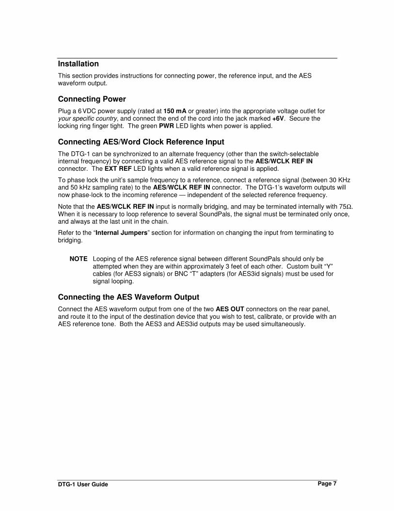
Installation
This section provides instructions for connecting power, the reference input, and the AES waveform output.
Connecting Power
Plug a 6 VDC power supply (rated at 150 mA or greater) into the appropriate voltage outlet for your specific country, and connect the end of the cord into the jack marked +6V. Secure the locking ring finger tight. The green PWR LED lights when power is applied.
Connecting AES/Word Clock Reference Input
The DTG-1 can be synchronized to an alternate frequency (other than the switch-selectable internal frequency) by connecting a valid AES reference signal to the AES/WCLK REF IN connector. The EXT REF LED lights when a valid reference signal is applied.
To phase lock the unit’s sample frequency to a reference, connect a reference signal (between 30 KHz and 50 kHz sampling rate) to the AES/WCLK REF IN connector. The DTG-1’s waveform outputs will now phase-lock to the incoming reference — independent of the selected reference frequency.
Note that the AES/WCLK REF IN input is normally bridging, and may be terminated internally with 75Ω. When it is necessary to loop reference to several SoundPals, the signal must be terminated only once, and always at the last unit in the chain.
Refer to the “Internal Jumpers” section for information on changing the input from terminating to bridging.
NOTE Looping of the AES reference signal between different SoundPals should only be attempted when they are within approximately 3 feet of each other. Custom built “Y” cables (for AES3 signals) or BNC “T” adapters (for AES3id signals) must be used for signal looping.
Connecting the AES Waveform Output
Connect the AES waveform output from one of the two AES OUT connectors on the rear panel, and route it to the input of the destination device that you wish to test, calibrate, or provide with an AES reference tone. Both the AES3 and AES3id outputs may be used simultaneously.

DTG-1 User Guide Page 8
Operation
This section provides explanations of each rotary and DIP switch on the front panel of the DTG-1.
Using the Waveform Switch
The 16-position Waveform Switch allows you to select a variety of single and multiple-frequency test signals. The table below provides a detailed explanation of each switch position and function.
OFF
WAVEFORM
R ABP
CN
DM
ELFK
GJ H
Waveform Switch Settings
Position Waveform Note
OFF None Digital silence. The Amplitude Switch is disabled.
A 20 Hz sine wave
B 100 Hz sine wave
C 440 Hz sine wave in music, “A” for tuning
D 1 KHz sine wave
E 3 KHz sine wave
F 10 KHz sine wave
G White noise Indicates error with amplitude > -10 dB
H Pink noise Has constant energy per octave from 20 Hz to 20 KHz.
J 1 KHz sine wave, with left/right ID One gap = Left Two gaps = Right
K Sine wave sweep Logarithmic sweep, 20 Hz–20 KHz, over a 6 second interval.
L Sine wave steps Steps at 20 Hz, 100 Hz, 400 Hz, 1 kHz, 3 kHz, 10 kHz, 20 kHz. Each step 1 second duration
M Sine wave FS/64 Current sample rate / 64. Provides high precision true 24-bit source, no waveform interpolation.
N Phase ID An asymmetrical signal to allow detection of phase reversals in analog devices.
P AES Ref pass through Allows input reference channel status bits to be modified via Mode DIP Switch settings. Mode is unity gain; Amplitude Switch is disabled.
R 1 KHz with L/R ID Provides 1 second of continuous tone on the left channel followed by 3 seconds of continuous tone on the right channel.
NOTE Refer to the “Error Conditions” section for a list of waveform conditions which will cause the red ERR LED to light.
DTG-1 User Guide Page 9
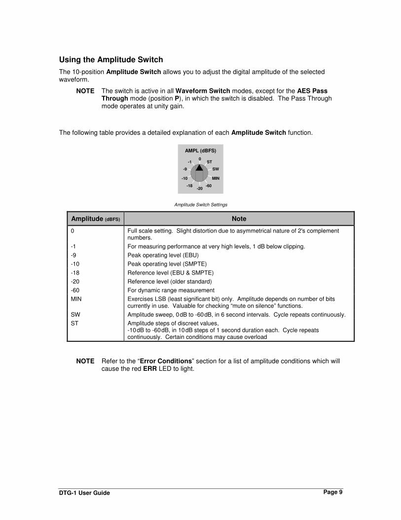
Using the Amplitude Switch
The 10-position Amplitude Switch allows you to adjust the digital amplitude of the selected waveform.
NOTE The switch is active in all Waveform Switch modes, except for the AES Pass Through mode (position P), in which the switch is disabled. The Pass Through mode operates at unity gain.
The following table provides a detailed explanation of each Amplitude Switch function.
AMPL (dBFS)
0ST
SW
MIN
-60-20
-18
-10
-9
-1
Amplitude Switch Settings
Amplitude (dBFS) Note
0 Full scale setting. Slight distortion due to asymmetrical nature of 2's complement numbers.
-1 For measuring performance at very high levels, 1 dB below clipping.
-9 Peak operating level (EBU)
-10 Peak operating level (SMPTE)
-18 Reference level (EBU & SMPTE)
-20 Reference level (older standard)
-60 For dynamic range measurement
MIN Exercises LSB (least significant bit) only. Amplitude depends on number of bits currently in use. Valuable for checking “mute on silence” functions.
SW Amplitude sweep, 0 dB to -60 dB, in 6 second intervals. Cycle repeats continuously.
ST Amplitude steps of discreet values, -10 dB to -60 dB, in 10 dB steps of 1 second duration each. Cycle repeats continuously. Certain conditions may cause overload
NOTE Refer to the “Error Conditions” section for a list of amplitude conditions which will cause the red ERR LED to light.

DTG-1 User Guide Page 10
Using the AES Level Switch
The 8-position AES Level Switch allows you to select the AES3 and AES3id output amplitudes.
AES LVL (dB)
0
-12-9
-6
-3 -21
-18
-15
The switch affects the output voltage levels (of the selected waveform) from both the AES and AES3ID output ports. 0 (zero) is the standard level, with voltages as indicated below:
• 4.5 V p-p for AES3 (on XLR)
• 1 V p-p for AES3id (on BNC)
Each position on the switch is marked with amplitude in dB. The total range provided is from 0 (zero) to -21 dB.
Note that the switch is typically used for testing a device’s digital threshold, and evaluating the noise margin (or “eye opening” response) of an AES receiver.
Setting the Sample Frequency
In terms of reference priority, the external AES/WCLK REF IN connector has the highest priority followed by the Sample Frequency Switch.
• If a valid AES or Word Clock reference is connected to the DTG-1 (between 30 KHz and 50 KHz), the system will lock to it and the front panel EXT REF LED will light.
• If you elect to use an external reference and the EXT REF LED does not light (or if it flashes), the incoming reference signal is invalid, and the DTG-1 can not lock to it. In this condition, re-check the external reference or disconnect it and use an internal frequency.
• The two-position Sample Frequency Switch allows you to select an internal sampling frequency of either 48 KHz or 44.1 KHz.
The switch is active only when no external reference is connected to the AES/WCLK REF IN input.
48K
44.1KFS
When internal reference is used in this manner, note that the front panel EXT REF LED is off.

DTG-1 User Guide Page 11
Using the Mode DIP Switch
The 8-position Mode DIP Switch provides settings for both consumer and professional functions.
1 2 3 4 5 6 7 8
MODE
1
0
Please note:
• 0 = Down • 1 = Up
Two function tables are provided on the following pages — one for consumer mode and one for professional mode. Each mode allows you to manually set and test devices that respond to certain CSB (channel status bit) functions. Note that switch 1 changes the function of switches 2-8 between the consumer and professional modes.
NOTE The channel status bits for Sample Rate are unaffected by the settings of the Mode DIP Switch. Those bits are automatically set within the DTG-1, based on the current reference setting.
Consumer Mode
The table below lists consumer mode settings (with switch 1 set to 0). This mode provides many functions that are typically used for testing consumer equipment, such as CDs and RDATs.
DIP Switch Settings — Consumer Mode
Position Usage Function
1 Sets switches 2-8 to consumer functions
0 = Consumer mode
2 Emphasis 0 = None 1 = 50/15 µs emphasis
3 Copy Protection 0 = Copy inhibited 1 = Copy permitted
4 Generation 0 = Copy 1 = Original
5-7 Unused
8 Dither 0 = Off 1 = On
Notes the following points on the consumer mode settings:
• Emphasis — switch setting affects both DTG-1 audio output and CSB content. This allows the test of devices with emphasis/de-emphasis functionality.
~ 50/15 is the standard CD emphasis. ~ This setting may indicate an error with high-amplitude, high-frequency test
signals.
• Copy Protection — switch setting affects CSB content only. This allows the test of devices such as RDATs that employ copy protection functionality, thus inhibiting the record mode.

DTG-1 User Guide Page 12
• Generation — switch setting affects CSB content only. This allows the test of devices such as RDATs that employ “generation” functionality. Flags content as follows:
~ Original: allows one copy only to be made ~ Copy: prevents further copies from being made
• Dither — switch setting affects DTG-1 audio output only. When enabled, applies random modulation to the least significant of 20 active bits, thus improving resolution.
Professional Mode
The table below lists professional settings (with switch 1 set to 1). This mode provides a variety of functions that are typically used for testing professional AES-standard equipment.
DIP Switch Settings — Professional Mode
Position Usage Function
1 Sets switches 2-8 to professional functions
1 = Professional mode
2-3 Emphasis 00 = Not indicated 01 = None 10 = 50/15 ms emphasis 11 = Not indicated
4-5 Audio mode 00 = Not indicated 01 = Two-channel 10 = Single channel 11 = Stereo
6-7 Resolution 00 = 16 bits 01 = 20 bits 10 = 24 bits 11 = Reserved
8 Dither 0 = Off 1 = On
Notes the following points on the professional mode settings:
• Emphasis — switch setting affects both DTG-1 audio output and CSB content. This allows the test of devices with emphasis/de-emphasis functionality.
~ 50/15 is standard CD emphasis. ~ This setting may indicate an error with high-amplitude, high-frequency test signals.
• Audio Mode — switch setting affects CSB content only. Primary/secondary mode cannot be set.
• Resolution — switch setting affects both DTG-1 audio output and CSB content.
• Dither — switch setting affects DTG-1 audio output only. When enabled, applies random modulation to the least significant bit (identified by switch 6).

DTG-1 User Guide Page 13
Recommended Default Settings
This section provides two lists of recommended default settings for both consumer and professional devices.
Consumer Mode Defaults
Use the following default settings as an excellent starting point for testing consumer products:
• Depending on your system and requirements, set the Sample Frequency Switch to either 48 KHz or 44.1 KHz, or lock the DTG-1 to an external AES3id (or Word Clock) reference.
• Set Mode DIP Switch to consumer mode.
~ Set Emphasis off.
~ Set Copy Protection to copy permitted.
~ Set Generation to original.
~ Set Dither off.
• Set the Waveform Switch to 1 KHz Sine Wave (position D)
• Set the Amplitude Switch to -20 dB (reference level)
• Set the AES Level Switch to 0 (zero) dB
Professional Mode Defaults
Use the following default settings as an excellent starting point for testing professional AES products:
• Depending on your system and requirements, set the Sample Frequency Switch to either 48 KHz or 44.1 KHz, or lock the DTG-1 to an external AES3id (or Word Clock) reference.
• Set Mode DIP Switch to professional mode.
~ Set Emphasis off.
~ Set Audio Mode to not indicated.
~ Set Resolution to 20 bits.
~ Set Dither off.
• Set the Waveform Switch to 1 KHz Sine Wave (position D)
• Set the Amplitude Switch to -20 dB (reference level), or to the level used for your house reference.
• Set the AES Level Switch to 0 (zero) dB

DTG-1 User Guide Page 14
Interconnection
This section provides two DTG-1 interconnection diagrams.
• Generating Test Waveforms or “Leader” Tones
In this application, a house AES reference is connected to the DTG-1 to ensure that its output is in sync with input video. The reference input uses timing information only, not content. An AES reference tone waveform is connected to the DTR for use as a reference, test, or “leader” tone, as required.
AESWaveform
SoundPals DTG-1
Waveform
Amplitude
Mode
AES Level
FS
AES Out
AES In / Word Clock In
PWR
DTR
Reference From House
InputVideo
• DAT Performance and Copy Protection Tests
In this application, the DTG-1’s output is set to consumer mode in order to test the DAT’s digital inputs for proper copy protection and generation functionality. Other audio performance and calibration tests can also be performed as required.
DAT Recorder / Player
Consumer ModeOutput
SoundPals DTG-1
Waveform
Amplitude
Mode
AES Level
FS
AES Out
AES In / Word Clock In
PWR
Digital Input

DTG-1 User Guide Page 15
• DTG-1 Signal Distribution
In this application, rather than direct point-to-point connection, the DTG-1 is connected to the input of a facility’s audio/video digital routing switcher. This configuration allows all destination devices to be connected to the DTG-1 without complex patching.
A / V Digital
Routing Switcher
SoundPals DTG-1
Waveform
Amplitude
Mode
AES Level
FS
AES Out
AES In / Word Clock In
PWR
AES
Digital Input
AES
Waveform
To Destinations

DTG-1 User Guide Page 16
Internal Jumpers
This section provides details about the DTG-1’s internal jumpers.
NOTE For instructions on opening and closing the DTG-1, see “Inside the Module.”
The figure below shows the DTG-1’s internal jumper locations:
J6
GR
AH
AM
-PA
TT
EN
SY
ST
EM
SG
RA
SS
VA
LL
EY
, C
AL
IFO
RN
IAM
ad
e in
U.S
.A.
DT
G-1
MO
DU
LE
04
-02
32
-
J5
Word Clock Polarity Jumper
InputTermination
Jumper
• J5 is the Reference Input Termination jumper.
1
2
3
– To select a bridging input, strap the jumper between pins 2 and 3. This is the default jumper position (required for Word Clock).
1
2
3
– To select a 75Ω terminating input, strap the jumper between pins 1 and 2.
• J6 is the Word Clock Polarity jumper.
1
2
3
– To leave Word Clock reference normal, strap the jumper between pins 1 and 2. The rising edge is used as reference.
1
2
3
– To invert the Word Clock reference, strap the jumper between pins 2 and 3. The falling edge is used as reference.

DTG-1 User Guide Page 17
Troubleshooting
The table below lists several DTG-1 problems, and provides a variety of “checklist” procedures designed to solve them.
Problem Procedure
Power LED does not light, no outputs.
• Ensure wall supply is plugged in properly and power connection is tight, not loose.
• Check voltage from wall power supply for minimum 6 volts DC. Measure voltage at the supply connector, when disconnected from the DTG.
EXT REF LED does not light with an AES or a Word Clock input connected to AES/WCLK REF IN.
• If Word Clock is used, ensure that internal jumper J5 is set to Bridging (Hi-Z). This is the factory default position.
• For AES signals, ensure that the amplitude of the AES signal is not below 70mV p-p, when connected to the DTG.
• Ensure that sample rate of the reference input is not outside the 30-50KHz range.
No output on BNC or XLR AES outputs.
• Check that the unit is getting power.
Clicking sound in audio tones.
• If DTG is feeding a system with no input sample rate conversion, then the DTG sampling frequency is not locked to the system to which it is connected.
Error LED comes on. • Check that none of the conditions described in the following “Error Conditions” section are being met.
• Change settings or mode switch to eliminate the error condition.
NOTE Please contact the Simlatus factory if the problem still exists after completing the above procedures.
Error Conditions
Several combinations of front panel switch positions can cause the red ERR LED to light under certain conditions. When the LED lights, an error or overload condition exists which should be remedied immediately.
The following conditions will create an error LED indication. Use this list as a guide for identifying and preventing these conditions.
• Using Emphasis in conjunction with Linear Amplitude Sweep can create a waveform which will clip at the higher frequency settings.
• Using Emphasis at the higher frequency settings in conjunction with 0dBFS and -1dBFS amplitude settings.
• If the DTG-1 is locked to an External Reference that goes below 42 KHz sampling rate while in Log or Step Frequency Sweep waveform mode, the Nyquist sampling criteria will be violated and the Error LED will light.
• If the sampling frequency goes below 20 KHz rate.
• If White Noise or Pink Noise is selected and the Amplitude (dBFS) setting is >-10dBFS, the output waveform can go into clipping.
• If White Noise or Pink Noise is selected and Linear or Step Amplitude Sweep is selected, an error will be created at levels of -10dBFS and above.

DTG-1 User Guide Page 18
Specifications
This section provides DTG-1 audio and environmental specifications.
Audio Specifications
Specification
AES3 output (terminated in 110 ΩΩΩΩ)
Nominal amplitude 4.5 V p-p
Amplitude range 0–21 dB
Rise time 5–30 ns
Output impedance 110 Ω ±20% (0.1–6 MHz)
Output com. mode <-30 dB (0–6 MHz)
AES3id Output (terminated in 75 ΩΩΩΩ)
Nominal amplitude 1 ±0.05 V p-p
Amplitude range 0–21 dB
Rise time 37 ±7 ns
Output impedance 75 Ω
Return loss >15 dB (0.1–6 MHz)
DC on output <50 mV
AES3ID Reference Input
Min. eye opening 165 mV x 0.5 UI (typical level 1 V p-p)
Input impedance 75 Ω or bridging
Return loss >15 dB (0.1–6 MHz)
Sample frequency 30–50 KHz
Word Clock Reference Input
Amplitude 4.5 ±1 V p-p
Waveform Square-wave at Fs
Phasing + edge coincident with desired audio sampling instant. Use jumper J6 to invert.
Input impedance >5 KΩ
Options
RT-2, 1RU rack tray for mounting up to 3 units
Power supplies:
• PSU-1, 90-260V 50/60Hz in-line power supply with detachable IEC power cord
NOTE All specifications listed above subject to change without notice.

DTG-1 User Guide Page 19
Environmental Specifications and Dimensions
Parameter Specification
Dimensions (less connectors)
5.2W x 1.62H x 6.625D 13.2 x 4.1 x 16.8 cm
Power <150 mA @ 6 Vdc
Operating Temp. 10 – 50 °C
Operating Humidity 10 – 90% RH non-condensing

DTG-1 User Guide Page 20
Inside the Module
In This Section
This section provides instructions for opening and closing the SoundPals DTG-1 module to gain access to the internal circuit board.
NOTE The internal circuit board should only be removed from the module if you want to set jumpers.
Before You Begin
Check the following items before opening the module and attempting to remove the internal circuit board:
If required, remove the SoundPals module from the rack tray. Disconnect the power supply from the front of the product. Disconnect all input and output cables. Perform the remaining steps only in a static free environment. Make sure that you and
the product are both grounded.
The following tools are required: • #2 Philips screwdriver
Opening the Module
Use the following steps to open the DTG-1 module:
1. On the rear panel, remove the four Phillips screws from the four corners of the SoundPals module.
2. On the rear panel, remove the two Phillips XLR mounting screws from the module.
3. On the rear panel remove the BNC nuts and associated lock washers.
4. On the front panel, remove the three knobs for the Waveform Selection Switch and Amplitude and AES LVL Select switches.
5. Remove all four screws on the front panel using the #2 Philips screwdriver.
6. Pulling the front panel, carefully draw the internal circuit board and front panel assembly from the housing.
CAUTION Keep the case horizontal so that the BNC bushings stay with the connectors.
7. Set the housing and all mounting hardware in a safe place.
Closing The Module
Use the following steps to close a SoundPals module:
1. Ensure that product label is on the bottom.
2. Carefully slide the internal circuit board and rear panel assembly through the housing. Keep the case horizontal so that the BNC bushings stay with the connectors.
3. Replace all BNC nuts and associated lock washers on the rear panel of the module.
4. Start all four screws on the front panel.
5. Replace all Philips XLR mounting screws on the rear panel of the module.

DTG-1 User Guide Page 21
6. Now tighten all four screws on the rear panel followed by tightening all four on the front panel.
CAUTION Do not over tighten the screws.
7. Now tighten all four screws on the rear panel followed by tightening all five on the front panel.
8. On the front panel replace the three knobs removed earlier.
External Power
About Power Supplies
An external power supply conforming to the specifications listed in the following “Power Supply Specifications” section must be used to guarantee that published SoundPals performance figures are met. Any power supply meeting these specifications will supply adequate power for a single SoundPals module. Although the specification is written for power supplies running from AC line inputs, DC (battery) sources may be used if they meet all of the listed requirements.
CE Compliance
For CE compliance, the power supply that you use must comply with the following requirements:
• Low Voltage Directive 73/23/EEC • EMC Directive 89/336/EEC • EMC Directive 93/68/EEC • The connector locking ring must be tight.
Portable Power Sources
For portable SoundPals power sources, sealed lead-acid, nickel cadmium or alkaline primary batteries may be used. However, the maximum voltage must not exceed 8.6 volts, and a minimum of 5.6 volts is required for normal operation. Maximum current drain will be 161 mA.
Power Supply Specifications
The following specifications must be met over all anticipated operating conditions including AC power line range, temperature range, etc.
Parameter Specification
Output voltage 5.6 V minimum (measured at trough of ripple) at 161 mA constant current.
8.6 V maximum (measured at peak of ripple) at 105 mA constant current.
Ripple voltage 2 V p-p at 700 mA constant current.
400 mV p-p at 700 mA constant current with external 2200 µF capacitor.
Connector Switchcraft 761K with center positive, sleeve negative.