Embed Size (px)
Citation preview
CECOM
0
<CORROSION PREVENTION & CONTROL APPLICATIONS GUIDE
DTICdELECTE IEL&AP 181989 l
March.31, 1987 3 APR ECTE
Appreed for publc releciso
Dimtrution Unlimited
Analytics, Inc.766 Shrewsbury Avenue
Tinton Falls, NJ 07724
Charles P. Lascaro(201) 741-3353
89 L/ ,90o/&
TABLE OF CONTENTS
Page
1. Introduction. .. ...................... .... 1
2. Corrosion Mechanisms, Tutorial. .. .................. 22.1 General .. ............ ................ 22.2 Basic Corrosion Mechanism Types-. .. ............... 3
2.2.1 Direct Chemical Attack .. ................ 32.2.2 Galvanic Corrosion .. .. ................. 42.2.3 Corrosion Rate Factors .. ................ 6
2.2.3.1 Temperature .. ................. 62.2.3.2 Time. .. .................... 62.2.3.3 Moisture. .. .................. 72.2.3.4 Contaminants. ... .. .............. 7
a. Industrial Contaminants. .......... 7b. Processing Contaminants. .......... 8c. Field Contaminants .. ............ 9
2.2.3.5 By-products of Corrosion. .. ......... 12
2.3 Specific Forms of Electronic Corrosion .. .. ...........132.3.1 Pitting .. ........... ........... 132.3.2 Galvanic Couples. ............ ....... 172.3.3 Stress Corrosion. ............ ....... 202.3.4 Fretting Corrosion. ............. ...... 262.3.5 Hydrogen Embrittlement. ............ .... 262.3.6 Intergranular Corrosion .. ........... .... 282.3.7 Exfoliation Corrosion .. .......... ...... 302.3.8 Filiform Corrosion. ........... ....... 302.3.9 Silver Migration. ........... ........ 322.3.10 Direct Chemical Corrosion .. ........... ... 36
2.4 Ilectronic Design Factors*.. ........... ....... 452.4.1 Galvanic Couples. ............ ....... 452.4.2 Contacts. ............ ........... 59
2.4.2.1 General. ............ ....... 592.4.2.2 Pin and Socket Corrosion. .. ......... 60
2.4.3 Joining, Soldering, Bonding .. ............. 622.4.3.1 Insulated Wires, point-to-point .. ...... 62 k )2.4.3.2 Thermobonding. ............ .... 622.4.3.3 Soldering. ........... ....... 63
2.4.4 Antennas. ............ ............ 642.4.5 Connectors. ............ ...........66
'2.4.6 Waveguides. ............ .......... 66 i2.4.7 Case Designs, Seals, Gaskets. .............. 67 02.4.8 Case Hardware .. ........... ......... 71 13
2.5 Manufacturing Processes.. .. .......... ..... .. 712.5.1 Cleanliness .. ............ ...... .. 722.5.2 Soldering Fluxes. ........... ........ 72A2.5.3 Finishes, Platings, Coatings ... ........... 742.5.4 Repairs/Fixes. .. ................... . 74 Codes
(I " or
Page
2.6 Corrosion Resistance Testing ........ ................. 75
2.6.1 Panel Testing ........ ..................... ... 752.6.2 Corrosion Resistance Testing of Electronic Systems . . 76
2.6.2.1 Rain Test ....... .................. ... 772.6.2.2 Humidity ....... ................... ... 772.6.2.3 Fungus ........ .................... ... 782.6.2.4 Salt Fog ....... ................... ... 792.6.2.5 Leakage Immersion ..... .............. .. 81
3. Lessons Learned ........... ......................... ... 823.1 Waveguide Corrosion ......... ...................... ... 823.2 Antenna Corrosion ......... ....................... ... 833.3 Connector Pin Corrosion ........ .................... ... 843.4 Printed Circuit Board-Connectors ..... ............... ... 843.5 Kovar-Glass Seals ......... ....................... ... 853.6 Plastic Encapsulated ICs ....... ................... ... 853.7 Lead Wire, Tabs .......... ........................ ... 88
4. Corrosion Prevention Summary ........ .................... ... 924.1 General .............. ........................... 924.2 Corrosion Prevention Measures During Acquisition* .. ..... ... 93
4.2.1 Concept Exploration Phase ..... ............... .. 934.2.2 Demonstration & Validation Phase ... ........... ... 93
4.2.3 Full Scale Development (FSD) ....... ........... .944.2.4 Production ......... ...................... .. 95
4.3 Deployment .......... ..... ............... 964.4 Material Selection & Use ....................... 97
4.4.1 General .......... ........................ ... 974.4.2 Galvanic Couples ....... ................... ... 97
4.4.3 Surface Treatments ....... ................. ... 994.4.4 Electrical Connectors ...... ................. ... 99
4.4.5 Metals, Selection & Use ...... ................ .100
4.4.5.1 Magnesium ....... .................. .101
4.4.5.2 Plating Systems ..... ............... .. 1014.4.5.3 Organic Coatings ...... ............... .1024.4.5.4 Conformal Coatings ....... .............. 103
4.4.6 Solder Flux ........ ...................... .. 104
4.4.7 Organic Materials ........ .................. .1044.4.8 Gaskets, "0" Rings & Seals .... ............. .. 1054.4.9 Conductive Gaskets ....... .................. .1054.4.10 EMI Gaskets ....... ...................... 106
4.5 Design Case Configurations To Minimize Corrosion... . ..... .106
4.5.1 General .......... ....................... .. 106
4.5.2 Case Designs ......... .................... .1074.5.3 Printed Wiring Assemblies, Microcircuits ......... .. 109
4.5.3.1 Materials ......... .................. 1104.5.3.2 Designs .......... ................... 1104.5.3.3 Processes ......... .................. 1104.5.3.4 Testing Inspection ..... .............. .111
ii
Page
5. Field Usage ............................. 112
6. Storage ............. .............................. .113
7. Do's & Don'ts ........................... 1147.1 "Do's" .............................. 1147.2 "Don'ts" ............. ........................... .. 117
8. Glossary ............................... 1208.1 Terms, Definitions ......... ...................... .1208.2 Acronyms ........... ........................... .. 1338.3 Related Specifications and Standards ... ............ ... 1358.4 References ........... .......................... .. 1418.5 Pamphlets, Handbooks ........ ..................... .. 144
9. Contractual Clauses for Acquisition .... .... ............... .. 1509.1 Concept Exploration ......... ...................... .1509.2 Demonstration Evaluation ....... ................... .. 1519.3 Full Scale Development (FSD) ....... ................. .153
9.3.1 Suggested Warranty Clause Definitionof Corrosion Failures ....... ................. .151
10. Conclusions ............ ............................. .155
List of Figures
Figure 2.2.2 Typical Galvanic Corrosion Cell ...... ............ 5Figure 2.3.1.1 Corroded Beryllium Copper Spring Wire Contacts . ... 15Figure 2.3.1.2 Corrosion of Gold Plated Pins .... ............. ... 16Figure 2.3.1.3 Corrosion Growth at Pinholes .... ............. ... 16Figure 2.3.2.1 Electrolytic Corrosion ELC Sectioned View Fixed
Composition Resistor ...... ................. ... 18Figure 2.3.2.2 Transistor Bond Couple Corrosion Plastic
Transistor ......... ...................... . 19Figure 2.3.3.1 Example of Stress Corrosion Cracking .. ......... ... 22Figure 2.3.3.2 Illustration of Stress Corrosion Cracking of a
Kovar Lead Wire in a Printed Circuit Board ... ...... 23Figure 2.3.3.3 Corroded Hermetic Seal Pin, Kovar to Glass ....... .. 24Figure 2.3.6 Intergranular Corrosion of 7075-T6 Aluminum Adjacent
to Steel Fastener ....... ................... ... 29Figure 2.3.7 Exfoliation Corrosion ...... ................. ... 31Figure 2.3.8 Filiform Corrosion ....... .................. ... 33Figure 2.3.9.1 Silver Dendrite ........ .................... ... 34Figure 2.3.9.2 Silver Migration (SM), Variable Ceramic Capacitors . . 35Figure 2.3.10.1 PWA Conductor Corrosion ...... ................ .. 38
iii
Pa ge
Figure 2.3.10.2a Printed Contact Corrosion and Migration ofCorrosion Products .......................... .. 41
Figure 2.3.10.2b Board Edge Corrosion ...... ................. ... 41Figure 2.3.10.3 End-Seal Migration (ESM) Fixed Ceramic Capacitors . . 42Figure 2.3.10.5 Lead Wire Corrosion (LWC) Fixed Metallic Film
Resistor ......... ....................... ... 44Figure 2.3.10.6 Case Corrosion Fixed Tantalum Electrolytic
Capacitors ......... ...................... . 46Figure 2.3.10.7 Microbial Corrosion (MC) Bottom View of
Transistor Header ....... ................... .. 47Figure 2.4.4 Antenna Corrosion of Plated Aluminum Dipoles ......... 65Figure 2.4.6.1 Corroded Flexible Waveguide ..... .............. ... 68Figure 2.4.6.2 Stress Cracked Waveguide ..... ............... .. 68Figure 2.4.7 Corrosion Due to Moisture Entry in Gasket Sealed
Enclosure ......... ....................... ... 70Figure 2.5.1 Production Line Cleanliness Tester ... .......... . 73Figure 3.4.1 Printed Contact Corrosion ..... ............... .. 86Figure 3.4.2 Gold Plated Pin Contact ...... ................ .. 86Figure 3.5 Corroded H.S. Pin ........ .................. ... 87Figure 3.6.1 Typical Plastic Devices ...... ................ .. 89Figure 3.6.2 Polarity Schematic ....... .................. ... 90Figure 3.6.3 O-Bias, DW + NACI ....... ................... .. 90Figure 3.6.4 Demetallization of Base Aluminum (DW) .. ......... ... 91Figure 3.6.5 Demetallization of Base Aluminum (HCI) ........... .. 91Figure 4.4.5.4 Corrosion Protection Vs. Conformal Coating
Thickness .......... ...................... .104
List of Tables
Table 2.2.3.4.1 Organics as Source of Corrosive Vapor .... ......... 10Table 2.4.1.1 Table V Compatible Couples ..... .............. .. 49Table 2.4.1.2 Preventing Galvanic Corrosion .... ............. .. 50
iv
Corrosion Prevention & Control (CPC) Applications Guide
1. Introduction
The purpose of this Guide is to provide Life Cycle corrosion
prevention and control information, and guidance to design
engineers, quality control personnel, inspectors and procurement and
contractual personnel, who are involved in the development, testing
and acquisition maintenance, storage and repair of CECOM electronics
and communication equipments. The scope of this guide is limited to
the prevention and correction of corrosion failures, and control of
associated design and manufacturing measures, which relate to CECOM
electronics. The guide includes a short tutorial on corrosion
mechanisms, a listing of related electronic failure types,
prevention and quality control measures necessary during
acquisition, warranties, and preventive maintenance measures
necessary during storage, fielding, repair, and overhaul.
-- ., , | | | |1
2. Corrosion Mechanisms, Tutorial
2.1 General
Corrosion is the undesirable deterioration of materials resulting
from reactions of the materials with their environment. In
electronic equipments, some corrosion forms are not always
apparent. It can be very difficult to detect hidden deterioration
during a catastrophic electronic or mechanical failure. Many times
corrosion is a root cause of electrical failures; which can only be
discovered after a thorough failure analysis.
Current technology, such as Large Scale Integration (LSI) or Very
High Speed Integrated Circuitry (VHSIC), protects complete sensitive
circuit functions in a sealed package but can still be.subject to
corrosion because of defective seals and contaminants contained in
the package. Such failures can occur with minute corrosion
situations, but while minute, their effect can be catastrophic
because of the miniaturized scale of design and the critical
function of the circuit. 0
It has been postulated that corrosion is one of the greatest cause
of failures in electronics and that annual costs of such failures
nationwide, due to resulting lack of system availability and
maintenance is in the hundreds of billions of dollars.'
2
2.2 Basic Corrosion Mechanism Types
All of the various types of corrosion situations or occurrences can
be grouped into two basic types as follows:
Direct Chemical Attack
Galvanic Corrosion Cell
2.2.1 Direct Chemical Attack
Direct chemical attack results when materials corrode and
deteriorate as a result of exposure to a corrosive environment such
as: Chemical fumes, acids, activated solder fluxes, water or
moisture intrusion, and, in many cases, moist air. Reaction rates
and extent of damage depends on the materials involved, their area
of contact and temperatures in which the reactions occur. This type
of corrosion usually occurs on electronic hardware such as: cases,
panels, clamps, shafts, contacts, waveguides, screws, bolts, etc.
On painted surfaces, protection of the paint is lost when the paint
lifts, bubbles or blisters; due to surface damage or poor adhesion
at the paint-to-the-metal interface. Usually, such corrosion is
easily identified because it is visible. This type of corrosion
usually does not immediately cause failure, but its immediate effect
is cosmetic. Protection against direct chemical attack is usually
achieved by good quality platings, paints, coatings or treatments
which form a protective nonreactive films.
3
2.2.2 Galvanic Corrosion
Galvanic corrosion is a form of electrochemical corrosion that
occurs when two dissimilar metals are in contact with one other in
the presence of an electrolyte. This type of reaction, similar to
that which occurs in a simple battery, causes a flow of current from
anode to cathode (Figure 2.2.2). The reaction at the anode is
always oxidation which tends to destroy the anode metal by causing
it to go into solution as ions. The reaction at the cathode is
always reduction; involving the liberation of hydrogen and the
formation of alkali.
Theoretically, only the anode should corrode because the metal
cathode normally cannot be further reduced (i.e., bare metal), but
the cathode can be corroded by alkali. Thus, when two dissimilar
metals form a galvanic cell and the cathode metal is soluble in
alkali, both the anode and the cathode may corrode. Corrosion at
the anode, however, usually occurs at a faster rate. There are many
variations of a galvanic corrosion cell. Further descriptions can
be found in the referenced texts on corrosion or as shown in Figure
3.6.3 of the Para 3.6 which describes a complicated example of
galvanic corrosion occurring in a plastic coated transistor.
4
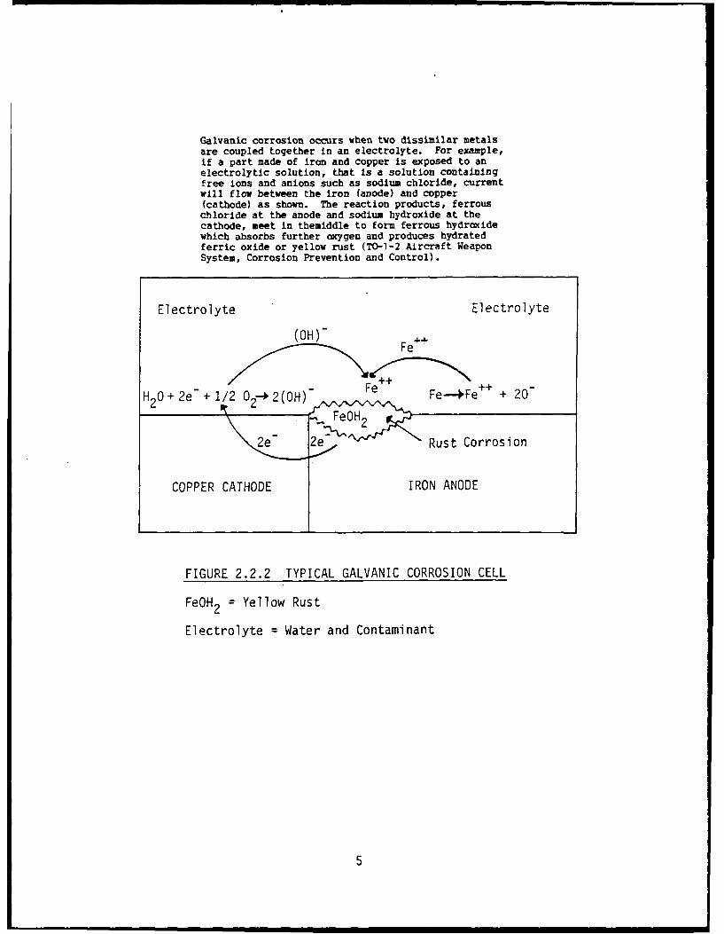
Galvanic corrosion occurs when two dissimilar metalsare coupled together in an electrolyte. For example,if a part made of iron and copper is exposed to anelectrolytic solution, that is a solution containingfree ions and anions such as sodium chloride, currentwill flow between the iron (anode) and copper(cathode) as shown. The reaction products, ferrouschloride at the anode and sodium hydroxide at thecathode, meet in themiddle to form ferrous hydroxidewhich absorbs further oxygen and produces hydratedferric oxide or yellow rust (TO-1-2 Aircraft WeaponSystem, Corrosion Prevention and Control).
Electrolyte Electrolyte
(OH)_ F Fe.
H20+2e +2/2 02-42(OH) Fe Fe-Fe + 20
FeOH 2
2e" 2e " Rust Corrosion
COPPER CATHODE IRON ANODE
FIGURE 2.2.2 TYPICAL GALVANIC CORROSION CELL
FeOH 2 = Yellow Rust
Electrolyte = Water and Contaminant
5
2.2.3 Corrosion Rate Factors.
Since corrosion is a progressive action, once it starts, it is
important to know under what conditions the rate of corrosion will
accelerate; since this will determine how soon, from the onset of
corrosion, a catastrophic failure can occur. Whenever an onset of
corrosion is discovered, it should be regarded as a potentially
catastrophic failure; which will occur in time depending upon the
following factors:
2.2.3.1 Temperature
Corrosion is generally accelerated by rising temperature. A good
rule-of-thumb is that all chemical reactions double their
acceleration rate with every increase of 100F temperature. This
would also apply to corrosion rates.
2.2.3.2 Time
Corrosion progresses with time, as long as the corrosion conditions
exist. Its progress can be interrupted by changes in conditions,
i.e. dryness, or eliminated by cleaning away contaminant and
applying MFP coatings, etc. but will continue if and/or when
conditions for corrosion are reestablished. Eventually, corrosion,
once started, will continue until a catastrophic failure occurs,
6
unless effective corrective measures are applied. Failures, due to
corrosion, have been experienced under tropical conditions from 3 to
6 months. For this reason, no slight corrosion spot can be ignored
as harmless or considered acceptable in CECOM material.
2.2.3.3 Moisture
Since contaminants must be in solution, moisture or humidity is an
essential element of corrosion. Items stored in a dry desert
condition corrode slowly or not at all, while items stored in a damp
tropical or marine condition corrode rapidly. Moisture is an
essential ingredient in corrosion mechanisms, in addition to a
contaminant; which can be present everywhere.
2.2.3.4 Contaminants
Electronic hardware and circuitry can be subjected to contaminants
from manufacture, storage, field usage and transportation.
Contaminants can cause direct chemical attack and, with moisture,
can form the electrolyte necessary for galvanic corrosion. Any
contaminant that will, in solution with moisture, provide ions and
anions for conductivity will also accelerate corrosion processes.
Contaminants can be classified as follows:"
7
a. Industrial Contaminants:
During the production process(es), equipment components can be
exposed to vapors, handling or contact contamination, fluxes,
etchants, ozone, outgassings, nitrates, and sulfates, etc.
Nitrates occur in rain water and are present in much higher
concentrations in the tropics due to decaying vegetation.
However, most nitrate contaminates result from industrial
processes. Sulfur dioxide and other sulfates also occur in
smoke and industrial gases. The combination of ozone, nitrate,
sulfate, and dust particles also contributes to deterioration of
organic insulation.
b. Processing Contaminants:
When packaged or sealed in the case or container, equipments
and/or components can be exposed to the outgassing from
incompletely cured plastics, rubbers, pottings, fluxes or any
synthetic organic compounds that were used in the manufacturing
or in the sealing process. Self-generating vapors usually
result from the outgassing or decomposition of plastics and
other organic materials or from the plating processes. Phenolic
base materials which can be used as insulators, standoffs,
circuit boards, knobs, etc., can emit ammonia and formic acid if
not properly baked out. The formic acid vapors react with the
8
lead in solder to form the grey-white lead deposits; often seen
on printed circuit boards. Zinc, cadmium, magnesium, lead, and
copper are very susceptible to corrosion from ammonia vapors.
Plastics, and some other organic materials such as packing
containers, when not completely cured, often liberate a host of
corrosive vapors. Moisture, hydrogen sulfide, and hydrochloric
and organic acids are the most prevalent. Outgassing is
dangerous during storage when the equipment is stored in a
closed area. Even small amounts of vapor can have a deleterious
effect; especially in miniaturized circuitry. Although
outgassing occurs at normal room temperatures, it is accelerated
in high temperature or low-pressure environments.
The most common source of corrosive vapors is from incompletely
cured organic material; examples of which are listed in Table
2.2.3.4.1. The extent of the attack depends on the degree of
cure, the plasticizer used, the temperatures, the type assembly,
and whether the assembly is in a closed or open container. Each
material use could be made of a plastic, which by choice could
be severely corrosive, somewhat corrosive, or not corrosive;
provided all other properties are satisfactory for the
application.
9
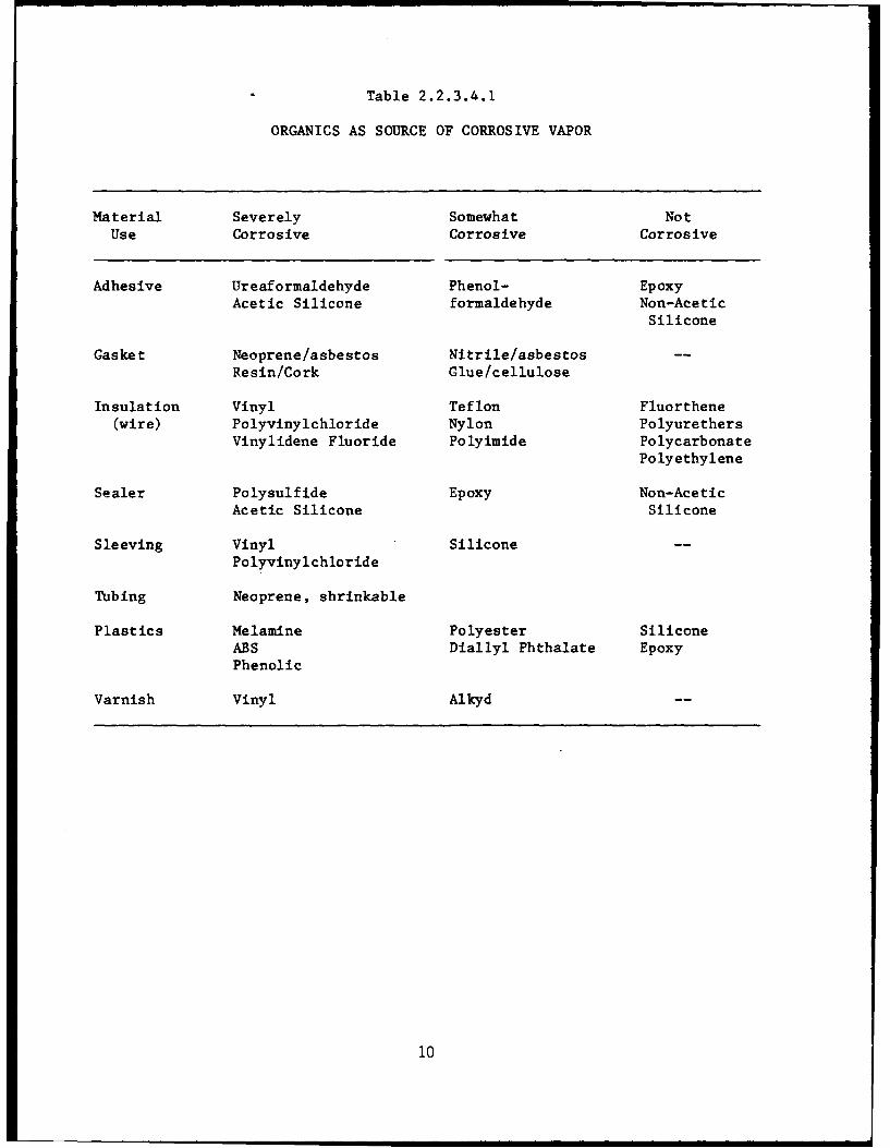
Table 2.2.3.4.1
ORGANICS AS SOURCE OF CORROSIVE VAPOR
Material Severely Somewhat NotUse Corrosive Corrosive Corrosive
Adhesive Ureaformaldehyde Phenol- EpoxyAcetic Silicone formaldehyde Non-Acetic
Silicone
Gasket Neoprene/asbestos Nitrile/asbestosResin/Cork Glue/cellulose
Insulation Vinyl Teflon Fluorthene(wire) Polyvinylchloride Nylon Polyurethers
Vinylidene Fluoride Polyimide PolycarbonatePolyethylene
Sealer Polysulfide Epoxy Non-AceticAcetic Silicone Silicone
Sleeving Vinyl Silicone
Polyvinylchloride
Tubing Neoprene, shrinkable
Plastics Melamine Polyester SiliconeABS Diallyl Phthalate EpoxyPhenolic
Varnish Vinyl Alkyd
10
Paper and wood also emit harmful vapors. Paper liberates
hydrogen sulfide, which tarnishes silver, copper, and brass.
Acid vapors from wood, especially oak, chestnut, and cedar, also
attack metals. These products are no longer generally used in
electronic assemblies; except in packaging materials.
c. Field Contaminants:
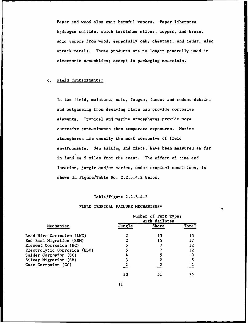
In the field, moisture, salt, fungus, insect and rodent debris,
and outgassing from decaying flora can provide corrosive
elements. Tropical and marine atmospheres provide more
corrosive contaminants than temperate exposures. Marine
atmospheres are usually the most corrosive of field
environments. Sea saltfog and mists, have been measured as far
in land as 5 miles from the coast. The effect of time and
location, jungle and/or marine, under tropical conditions, is
shown in Figure/Table No. 2.2.3.4.2 below.
Table/Figure 2.2.3.4.2
FIELD TROPICAL FAILURE MECHANISMS*
Number of Part TypesWith Failures
Mechanism Jungle Shore Total
Lead Wire Corrosion (LWC) 2 13 15End Seal Migration (ESM) 2 15 17Element Corrosion (EC) 5 7 12Electrolytic Corrosion (ELC) 5 7 12Solder Corrosion (SC) 4 5 9Silver Migration (SM) 3 2 5Case Corrosion (CC) 2 2 4
23 51 74
11
A study in the Panama Canal Zone exposed 18 different types of
approved military standard quality parts, in sample lots of 50
each per exposures site, to tropical conditions. The Table
shows that exposure at the shore, due to salt effects, can be
twice as corrosive. *"Corrosion of Army Electronic Equipment,"
by Charles P. Lascaro, USAET&DL, ECOM, Fort Monmouth, published
in 1972 Tri-Service Conference on Corrosion.
2.2.3.5 By-products of Corrosion
The nature of the corrosion by-product can accelerate or deter
further corrosive action by virtue of its physical or chemical
nature, i.e. aluminum oxide is dense, tough and adherent and forms a
protective film on the aluminum surface. Copper oxide is a
dielectric, which can increase contact resistance. The green patina
on copper surface, copper sulfide, is also a protective layer,
reducing but not eliminating further corrosive action. In many
cases, the nature of the by-product of corrosion provides a
protective layer to preserve structural integrity as on an aluminum
structure or it may cause conductivity circuit failures as on a
contact, switch or relay surface or a ground contact on an aluminum
chassis or ground plane. In some instances the by-products of
corrosion can act as a rectifier to AC signals.
12
2.3 Specific Forms of Electronic Corrosion:
While many forms of corrosion can and does occur in vehicle, truck,
tank or such structural forms, this guide will be confined only to
those forms of corrosion that have occurred and which can or will
affect the operational integrity of CECOM electronic, communication
or electrical systems. When a system failure occurs, system failure
analysis pinpoints the failure to a circuit function; and/or circuit
element or part. Quite often, the root cause can be corrosion.
Forms of corrosion which are important to electronic hardware and
circuitry are as follows:
2.3.1 Pitting Corrosion
Pitting is a common and severe form of localized corrosive attack on
thin metal sheets such as printed circuit paths, etc. which are
especially vulnerable since penetration of the metal at pit sites
can result in perforation. Perforation and the progressive nature
of corrosion will surely cause reduction in service life and
possible catastrophic failure. Pitting usually occurs in grain
boundaries, porous finish areas at highly anodic points on the metal
surface. It is primarily the result of localized cell action.
Concentration-cell action (differences in oxygen level) will
contribute to the formation of damage-causing corrosion products
that usually accumulate in such pits. It also occurs with porous
13
gold plating on copper alloy contacts. The plating pores create a
little corrosion cell which continues to expand until a hole or pit
is created. The initiation of localized or pit type corrosion can
occur because of incomplete films or coatings (e.g., damaged
protective oxide films), conformal coatings, etc; or in the presence
of substances that partially shield small areas on metal surfaces
(e.g., oxide scale or debris). Corrosive agents in solution will
accelerate pitting in such cases.
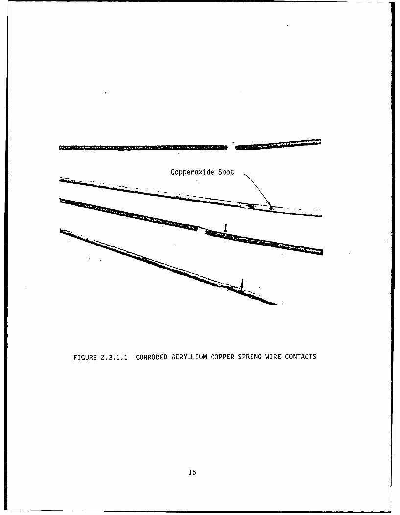
Some examples of pitting corrosion are shown in Figure 2.3.1.1,
2.3.4.2, 2.3.4.3.
Figure 2.3.1.1 shows spring wire contacts which failed because
corrosion products at the contact area plus make and break arcing,
creating a concentration cell and resultant pitting.
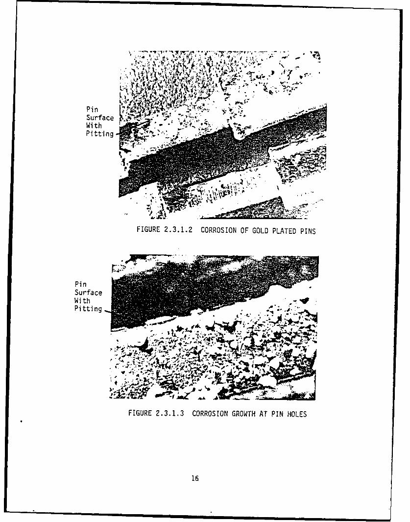
Figure 2.3.1.2 shows a gold-plated printed circuit connector pin
which pitted because of porous gold plating.
Figure 2.3.1.3 shows a closer view of the same connector pins with a
generally pitted surface.
All of the above failures could have been prevented with a nickel
underplate on as polished pin surface followed by a 50 microinch
gold plating.
14
Copperoxide Spot
FIGURE 2.3.1.1 CORRODED BERYLLIUM COPPER SPRING WIRE CONTACTS
15
- ..- s,., 1*vI J V a ' ~ y-c ~1 A4
Surface ~ 4kWith
FIGURE 2.3.1.2 CORROSION OF GOLD PLATED PINS
PinSurfaceWithPitting
- ~#. .71
f-4I-
.0 44 '-J,'
$-. Am*
FIGURE 2.3.1.3 CORROSION GROWTH AT PIN HOLES
16
Corrosion on aluminum and magnesium first appears as a white or gray
powdery blotch on the metal surface. When the deposits are cleaned
away, tiny pits or holes are visible. The by-products of such
corrosion can cause loss of seal in an equipment container or open
circuit in a contact or printed circuit element. Prevention can be
effected by plating on smooth or polished surfaces and/or thicker
nonporous platings. Usually an undercoating of nickel plating under
gold would be required.
2.3.2 Galvanic Couples
Galvanic couple corrosion occurs when two dissimilar metals are in
contact with one another in the presence of an electrolyte (solution
containing free ions and/or anions). It can be easily seen that in
a complex assembly as a communication system, subsystem, module,
printed circuit board assembly and/or a part, that couples can occur
in many instances and forms. In each case, the more anodic metal
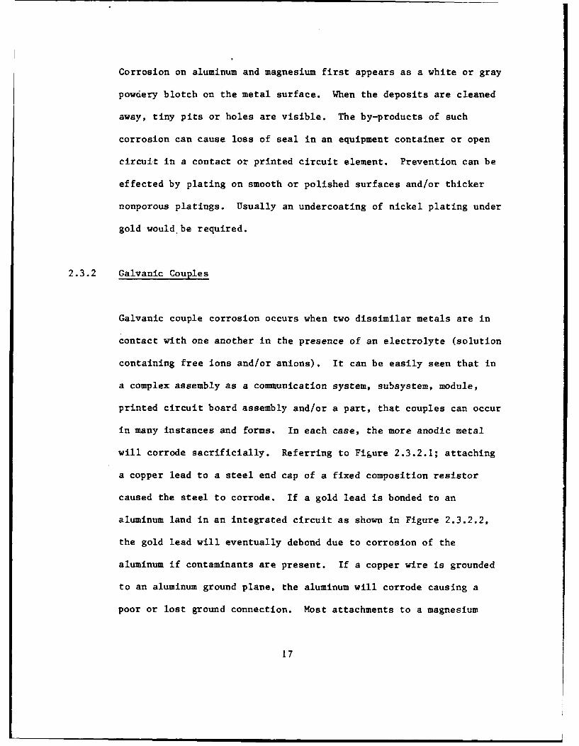
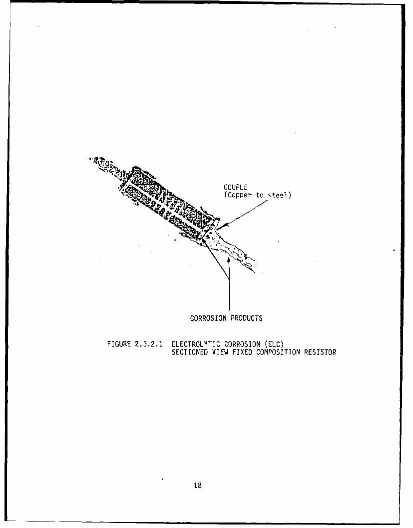
will corrode sacrificially. Referring to Figure 2.3.2.1; attaching
a copper lead to a steel end cap of a fixed composition resistor
caused the steel to corrode. If a gold lead is bonded to an
aluminum land in an integrated circuit as shown in Figure 2.3.2.2,
the gold lead will eventually debond due to corrosion of the
aluminum if contaminants are present. If a copper wire is grounded
to an aluminum ground plane, the aluminum will corrode causing a
poor or lost ground connection. Most attachments to a magnesium
17
COUPLE(Copper to steel)
CORROSION PRODUCTS
FIGURE 2.3.2.1 ELECTROLYTIC CORROSION (ELC)SECTIONED VIEW FIXED COMPOSITION RESISTOR
18
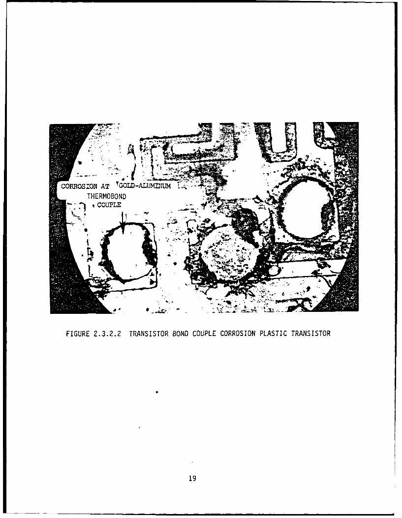
FIGURE 2.3.2.2 TRANSISTOR BOND COUPLE CORROSION PLASTIC TRANSISTOR
19
case will cause the magnesium to corrode. Stray potentials or
currents may either inhibit or accelerate corrosion; depending on
polarity and presence of an electrolytic medium. Corrosion is
usually prevented by not coupling metals outside the acceptable
groupings and preventing contaminants from coming in contact with
either metal by using coatings or barriers to separate anode and
cathode. Where possible, the area of contact for the anode should
be as large as the design will permit. This will spread the
corrosion over a larger area and permit a larger EMF in the
allowable sample. See Figure 2.4.1.1, which is really Table V of
MIL-F-14072.
2.3.3 Stress Corrosion
Stress corrosion failure results from a combined effect of tensile
stress and corrosion. Cold-working or straining, quenching (in heat
treatment), grinding, or welding may produce internal stresses.
Applied stress may be local or general, uniform and static, or
varying and cyclic. Stresses may exist in many
combinations/causes. The most destructive type of stress, however,
is that which is local and nonuniform. Under such conditions, the
stressed zones are subject to accelerated corrosion.
Metals that are subjected to applied stresses will develop a more
anodic nature at such areas under corrosive conditions. Adjoining
20
unstressed areas or less stressed areas will be less anodic or more
cathodic. Figure 2.3.3.1 shows a schematic of a stressed metal
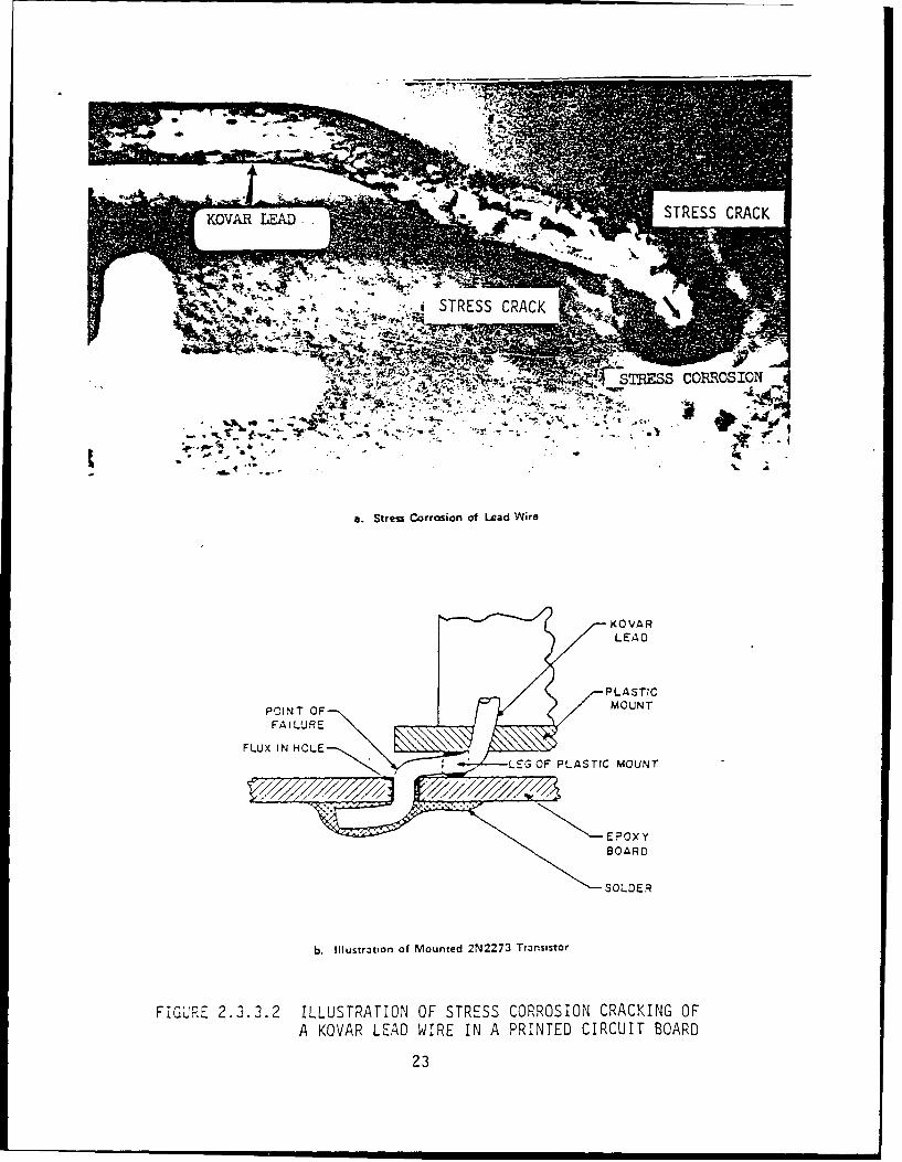
spring with corrosion initiated at notches. Figure 2.3.3.2a shows a
Kovar lead stressed at the insertion hole of the printed circuit
board where flux residues existed. Figure 2.3.3.2b is another
schematic illustrating stress corrosion at a soldered feed through
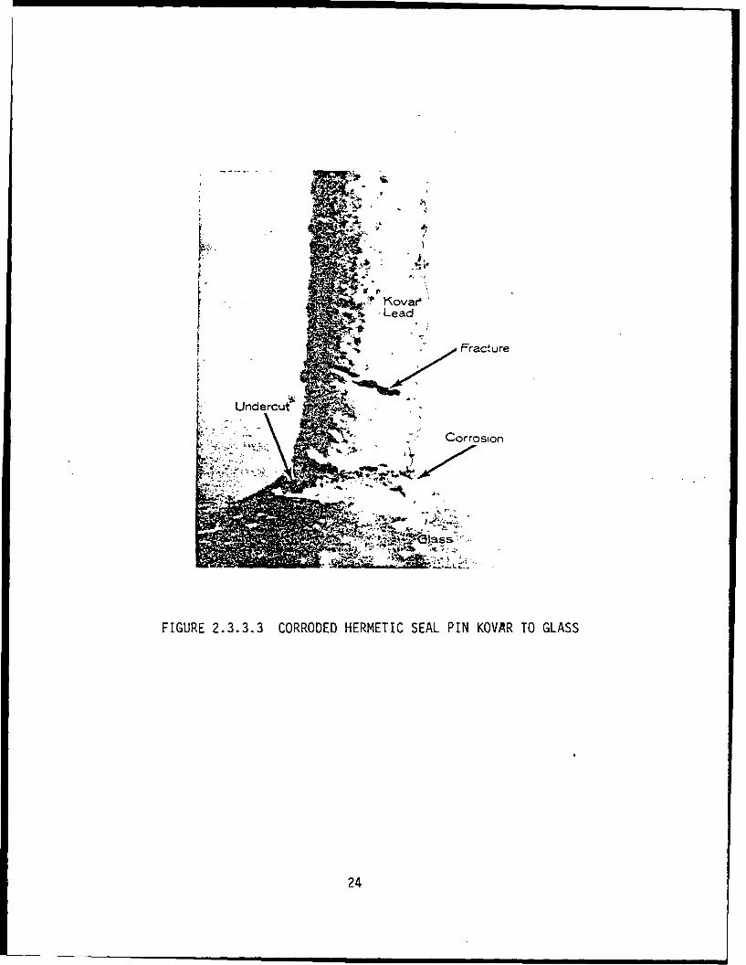
hole. Figure 2.3.3.3 is an actual photograph of a stressed Kovar
lead and resultant stress corrosion crack.
There are two principal types of failure associated with the
combined actions of stress and corrosions; these are
stress-corrosion cracking, and corrosion-fatigue failure. In
stress-corrosion cracking, fissures can be initiated and propagated
by corrosion of adodic areas that are generally concentrated
intergranularly. The presence of tensile stresses, residual or
applied, will accentuate concentration of the anodic action
resulting in rapid and localized intergranular cracking. With
intergranular cracking, high stress loads can be imposed on metal
adjacent and communicating with the crack, and can lead to
transgranular cracking.
Factors controlling stress corrosion include the type and amount of
stress in the metal; the nature, concentration, and temperature of
the corrosive environment; and the period of exposure. Any stressed
metal or high strength alloy is vulnerable to stress-corrosion
failure under certain conditions.
21
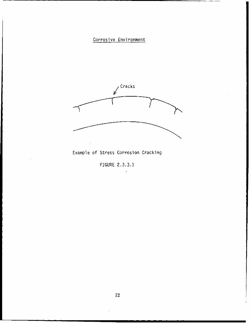
Corrosive Environment
Cracks
Example of Stress Corrosion Cracking
FIGURE 2.3.3.1
22
'STS CRACKES OROSO
a. Stress Corrosion of Lead Wire
KOVARLEAD
PLASTIC
POINT OF MOUNTFAILURE
FLUX IN HOLELEG OF PLASTIC MOUNT
EPOxyBOARD
SOLDER
b. Illustration of Mounted 2N2273 Transistor
FG'E2.3.3.2 ILLUSTRATION OF STRESS CORROSION CRACKING OFA KOVAR LEAD WIRE IN A PRINTED CIRCUIT BOARD
23
I-S
T, Kovara. -LeadI%
• , , . Fracture
Undercui
Corrosion
- -
FIGURE 2.3.3.3 CORRODED HERMETIC SEAL PIN KOVRR TO GLASS
24
Stress corrosion cracking can occur with some alloys of stainless
steels when they are exposed to chloride environments such as sodium
chloride, calcium chloride, etc. The ferric stainless steels will
suffer severe pitting from chloride exposure but are more resistant
to stress corrosion than the austenitic or martensitic alloys.
Copper alloys are also susceptible to stress-corrosion cracking.
Environments containing ammonia compounds in the presence of carbon
dioxide or oxygen are highly corrosive to the copper alloy. The
rate at which stress corrosion cracking occurs is greatly
accelerated with exposure to elevated temperatures. Cold-worked
brass with residual stresses is very susceptible to intergranular
cracking. The damaging effect of stress corrosion can be reduced by
avoiding residual stresses. High zinc content of brass increases
the susceptibility to this type of attack. Brasses that are
resistant to this form of deterioration usually have a zinc content
of less than 15 percent.
Aluminum alloys containing substantial amounts of such elements as
copper, magnesium, and zinc are also susceptible to stress-corrosion
cracking. This is especially true of the heat treated, high
strength 2000- and 7000-series alloys. Failures in these alloys
appear to be caused by fabricating or assembly stresses in
relatively thick sections. Annealing and thermal stress relieving
25
treatments will reduce the residual stresses, but they may also
change the characteristics of the alloy. Mechanical treatments such
as shot peening can be used to counteract the tensile stresses that
result after shearing. Stress corrosion usually occurs with steel
springs, bent leads, formed containers, flexible waveguides, etc.
2.3.4 Fretting Corrosion
Fretting corrosion is the term commonly applied to a type of metal
damage that may occur when two metal surfaces are in contact, under
load, and subjected to vibration, or slight relative motion. This
action, combined with some slipping, can open up unprotected spots
of activated metal and cause galvanic attack, that may result in
pitting and scarring and eventually cause fatigue or structural
failure.
2.3.5 Hydrogen Embrittlement
Hydrogen embrittlement is closely associated with stress corrosion
in that it causes surface and structural damage in high-strength,
iron-base and nickel-base alloys, and titanium. When these high
strength (or highly stressed) metals are cleaned, pickled,
electroplated, or welded, they may absorb hydrogen. The hydrogen
that is trapped in voids and cracks builds up pressure and causes
the metals to blister and crsck in what is known as "delayed
26
fracture". If high strength steel is not stress-relieved
immediately after plating, fracture can occur in as few as five
minutes. Hydrogen is easily picked up by titanium and causes marked
brittleness in the metal. Electrolyte tough-pitch copper is also
subject to hydrogen embrittlement when "bright annealed" in an
atmosphere containing hydrogen. The corrosion process, which
liberates hydrogen, may itself contribute to the hydrogen
embrittlement process.
Once hydrogen has been absorbed into a metal, it is very difficult
to remove. Therefore, special precautions must be taken to prevent
hydrogen absorption. Anodic pickling, oxidizing acid baths, and
heating cycles minimize absorption during pickling. Proper pickling
procedures before plating and careful control of the plating bath
and operating conditions also reduces the amount of hydrogen
absorbed.
Another way of preventing embrittlement is to avoid acid cleaning,
pickling, and electroplating. For example, use organic coatings, or
vacum deposited film or electroless coating processes instead of
electroplating. If plating is necessary, one of the following
procedures should be followed:
1. Use alkaline baths or other processes designed for low-hydrogen
pickup.
27
2. Use cadmium instead of zinc or chromium plate.
3. Shot peen before plating.
4. Stress relieve before plating and immediately afterward.
Materials not subject to hydrogen embrittlement, such as 300 series
18-8 corrosion-resistant steels or oxygen-free or deoxidized copper,
may also be used. Hydrogen embrittlement has been experienced in
springs and switch shafts.
2.3.6 Interaranular Corrosion
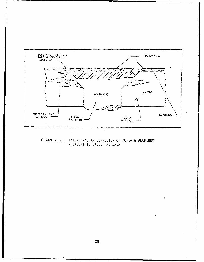
Intergranular corrosion is the attack that occurs at the grain
boundaries of some copper and nickel alloys. Improper heat treating
or welding of some chromium-nickel stainless steels causes this
alloy to become highly susceptible to intergranular corrosion.
Frequently, the grain boundaries are anodic to the main body of the
grain. If an electrolyte is present, rapid selective corrosion of
the grain boundaries occurs. Figure 2.3.6 shows intergranular
corrosion of 7075-T6 aluminum alloy adjacent to a steel fastener.
In this example, the grain boundaries are anodic to both the main
grain body and the steel fastener.
28
ELCCT!,oLYTr C,jT[RS PAINT FILM
TAINT FILM
(ANODE)
INT ERCG AtULAR CLADDING-CORROSICN STEEL 7075.T,
FASTENER ALUMINUM
FIGURE 2.3.6 INTERGRANULAR CORROSION OF 7075-T6 ALUMINUMADJACENT TO STEEL FASTENER
29
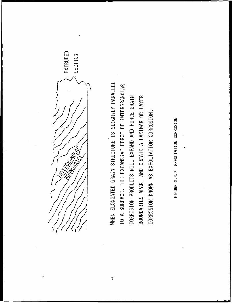
2.3.7 Exfoliation Corrosion
Exfoliation is a form of intergranular corrosion that is revealed by
a "lifting up" of the surface grains of a metal by the force of
expanding corrosion products occurring at the grain boundaries just
below the surface. It is visible evidence of intergranular
corrosion that most often occurs on extruded sections of metal where
grain thicknesses are usually less than in rolled forms. Figure
2.3.7 shows intergranular corrosion becoming visible at the surface
as exfoliation corrosion. Exfoliation corrosion is found primarily
in aluminum sheet around steel fasteners. Its prevention involves
separation between aluminum and steel with a barrier such as
zinc-chromate primer, for example, at the interface.
2.3.8 Filiform
Filiform corrosion takes the form of threadlike lines of strands.
It occurs on metal surfaces, under water-permeable coatings of clear
lacquers and varnishes, under paints, and sometimes under thin,
noncontinuous electro-deposits. It is often found on steel
surfaces, but may also develop on aluminum or zinc. Chemical
conversion treatment of the metal before application of organic
coatings will inhibit filiform corrosion.
30
LU =
X< LUJ
LU I
-JL
-1- LU
- - LU m= .() C) C)
- C) = C0-J U LL. U- < C) -
C/) C:) CD)
c/~ LU~ ~CCcl C::) L-)
L* C-,LU .Cz CDT
9:- a- 4
X )< - c -L~-LU c: - -
C/ LUJ .- J 09~-J =-=~ C)
S <C -- L- LU-LL- l LU
X LULFH-I 2= r
LUr C/) CD C/) l
C) J C) - C:)-- C.
LU C:: C.) LL.,
C) C)
LUJ= C) C) C:) C)
F - L.)
31
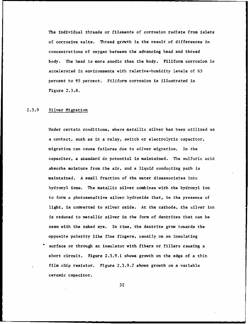
The individual threads or filaments of corrosion radiate from islets
of corrosive salts. Thread growth is the result of differences in
concentrations of oxygen between the advancing head and thread
body. The head is more anodic than the body. Filiform corrosion is
accelerated in environments with relative-humidity levels of 65
percent to 95 percent. Filiform corrosion is illustrated in
Figure 2.3.8.
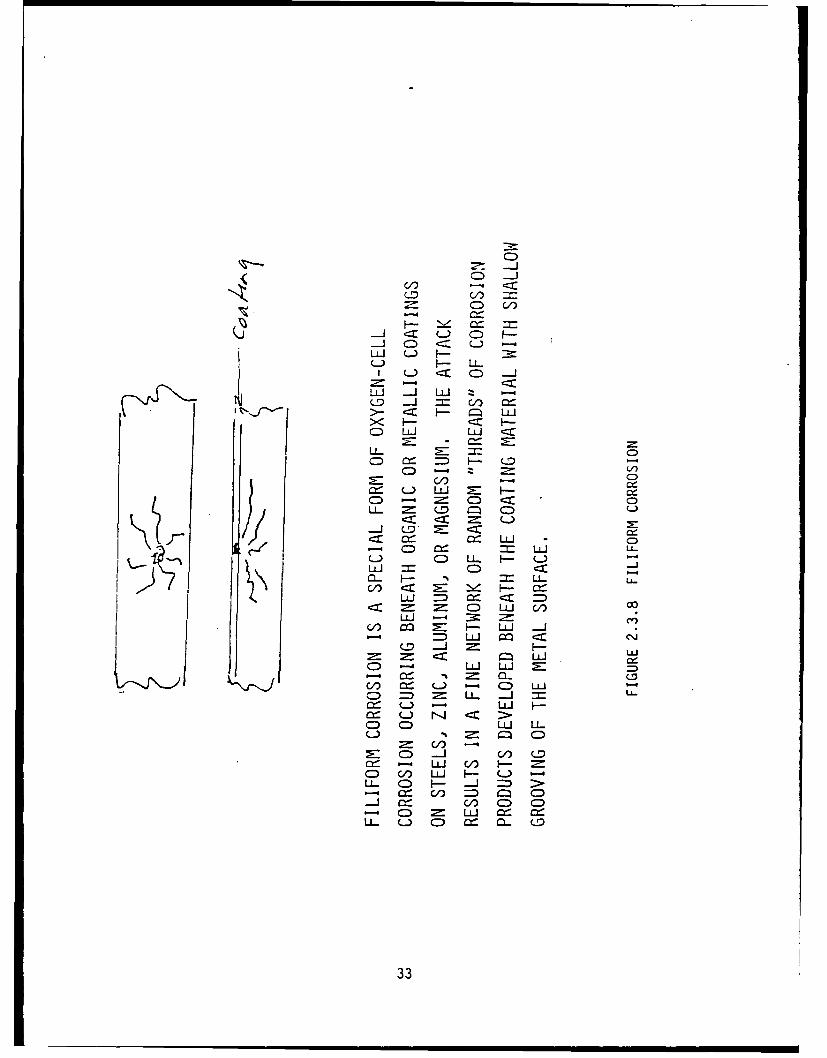
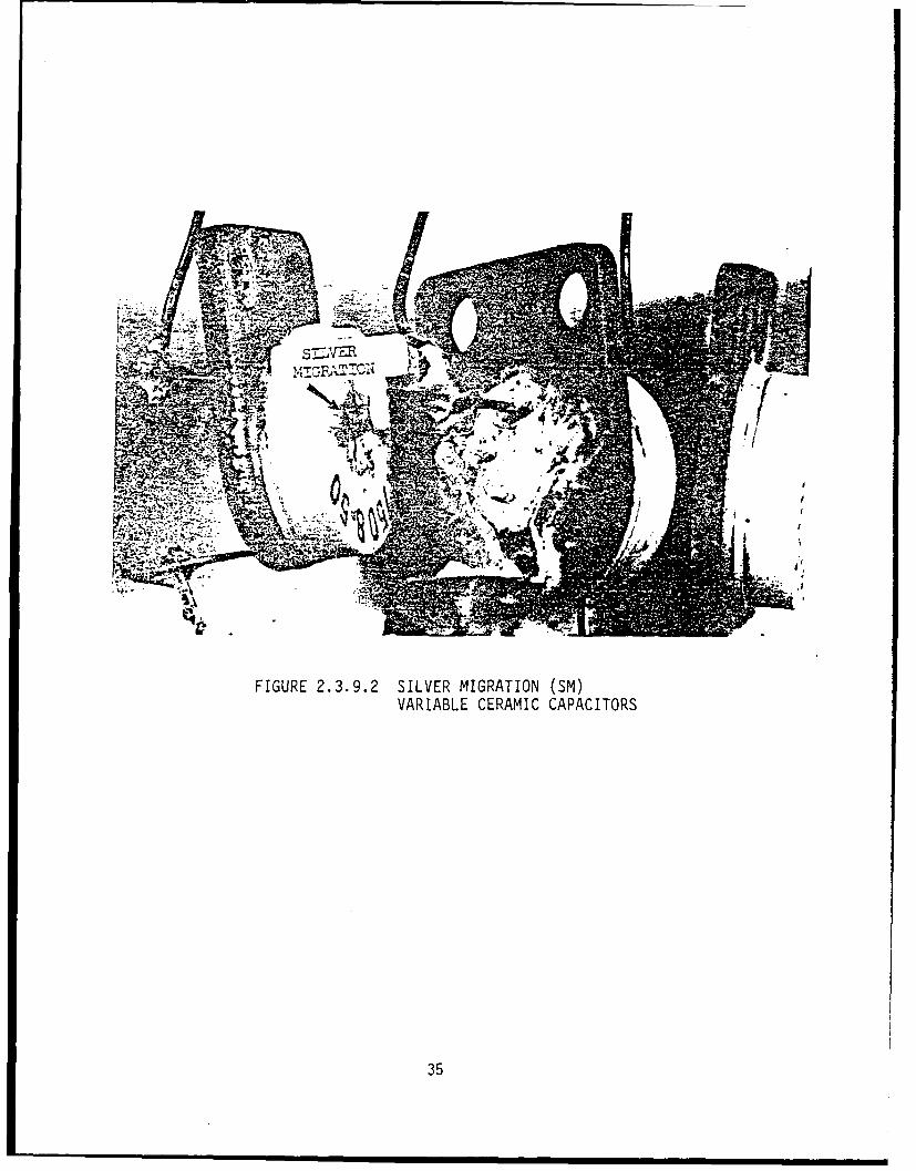
2.3.9 Silver Migration
Under certain conditions, where metallic silver has been utilized as
a contact, such as in a relay, switch or electrolytic capacitor,
migration can cause failures due to silver migration. In the
capacitor, a standard dc potential is maintained. The sulfuric acid
absorbs moisture from the air, and a liquid conducting path is
maintained. A small fraction of the water disassociates into
hydroxyl ions. The metallic silver combines with the hydroxyl ion
to form a photosensitive silver hydroxide that, in the presence of
light, is converted to silver oxide. At the cathode, the silver ion
is reduced to metallic silver in the form of dentrites that can be
seen with the naked eye. In time, the dentrite grow towards the
opposite polarity like fine fingers, usually on an insulating
* surface or through an insulator with fibers or fillers causing a
short circuit. Figure 2.3.9.1 shows growth on the edge of a thin
film chip resistor. Figure 2.3.9.2 shows growth on a variable
ceramic capacitor.
32
C/)
F- !Z~r (-) CD H
C-I-- LLw C ::) C: -
LU~ _.j LU Zi~j- j = - -
C) Ll LUJ C~
-L CD)
c:: L. L D
iiC/ CD
= LUCL CD 0 - LLH- .)
C~zc = C L L L )0
LU1 = -4 -LU H- U
Qv = LU I=~ LUJ
0- ~ ca- LUL)D L
Oo CD- H-I*
SL) r-4 ::c >CD (D LUJ U
F- CD , -j C1C= - j LJ CO
LL CD H- -J == = CD
C/3 CD CD0
L- 0. CD LU a-I
33
All.
MA=
At.~Wz
- o.11
z C)
tj0
& j,
FIGURE 2.3.9.2 SILVER MIGRATION (SM)VARIABLE CERAMIC CAPACITORS
35
2.3.10 Direct Chemical Corrosion
A form cf direct attack results from direct contact between metals
and corrosive liquids. As a first example, the green discoloration
of gold-plated copper circuitry on simple circuit boards is
considered. These circuit boards are commonly prepared by
silk-screening a pattern on the copper clad of an epoxy laminate.
The circuit pattern on the silk screen consists of solid lines of
polymerized resin. An organic coating material is transferred
through the silk screen, usually by a roller, to the copper surface
so that all of the copper, except for the circuit pattern, is
coated. After the coating material has dried, the entire laminate
and the exposed circuit pattern are gold-plated. After plating, the
coating on the laminate is removed with a suitable solvent, and the
unplated copper is etched away in a solution of ferric chloride.
What remains is the gold-plated circuit pattern on the epoxy
laminate.
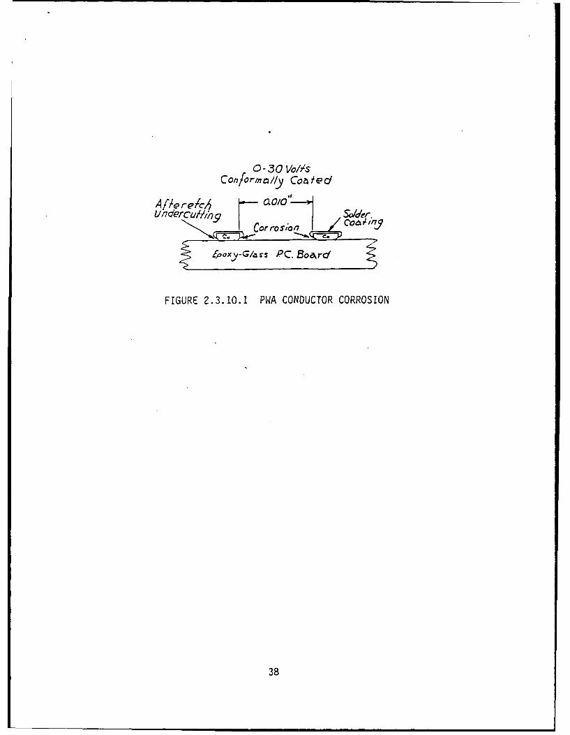
In one case, a green deposit was noted on circuit boards that had
been stored for about two years. Investigation revealed that minute
traces of ferric chloride etchant were trapped beneath portions of
the gold plating that projected beyond the edge of the copper
circuitry. Copper at the sides of the circuitry was not fully
protected from corrosion by the ferric-chloride residue (See
36
Figure 2.3.10.1). With subsequent processing of the printed board
and exposure to highly humid atmospheres, the area shown as a
corrosion site becomes green with copper chlorides.
Solder fluxes also contribute to direct chemical attack. Soldering
flux is a "substance that facilitates the wetting of a metal by
molten solder". For many metals, a good solder bond can be obtained
without flux if the surfaces are clean and free of oxides. It is
very difficult and expensive, however, to clean all metal surfaces
to be soldered. A more economical method is to use an appropriate
flux. (Caution: Many types of flux are activated and as a result
can leave highly corrosive residues.) The major functions of the
flux are to remove the oxide layers and form a protective film on
the exposed surface to prevent further oxidation before -the solder
is applied.
The fact that the flux can remove the often tenacious oxide film
indicates that it is chemically active. This implies that it is
also potentially corrosive, Oxtreme care should be used when
approving the use of activated or mildly activated fluxes. It is
essential that all residues be removed immediately following
soldering operations. Fluxes remove oxides at near normal soldering
temperatures, i.e., above 3500 F. Corrosion, on the other hand,
generally occurs near or just above room temperatures. In addition,
the flux may only react with the oxide layer and be inactive with
regard to the metallic subsurface.
37
-3 0 V//s
Con/orlmmlly Cob/edl
Cor rosto7
Z4ocxy-G/ars PC. Batr
FIGURE 2.3.10.1 PWA CONDUCTOR CORROSION
38
The terms "nonactivated", "mildly activated", and "activated" are
used to describe rosin-base soldering fluxes. Two government
specifications define these terms and specify the methods for
describing the corrosiveness of a flux. These are Federal
Specification QQ-S-571, which covers solid and flux-cored solders
used in hand-soldering operations, and Military Specification
MIL-F-14256, which covers liquid fluxes such as those used in
machine soldering.
QQ-S-571d specifies three types of rosin-core solders, type R
(nonactivated), type RMA (mildly activated), and type RA
(activated). In the case of liquid fluxes, as specified in
MIL-F-14256C, only two types are covered, type W (nonactivated), and
type RMA (mildly activated). Generally speaking, the cored solder
flux, type R, and the liquid flux, type W, are considered to be
equivalent, as are type RMA and type A. There is currently no
government specification for a liquid flux equivalent to type RA,
CECOM does not permit the use of RA flux in CECOM materiel. In
addition, RMA flux may only be used where approved cleaning and
inspection facilities exist.
Residues from active fluxes can degrade circuitry in two ways:
(1) by corroding solder joints or nearby regions where flux fumes
may settle and, (2) by reducing insulation resistance, particularly
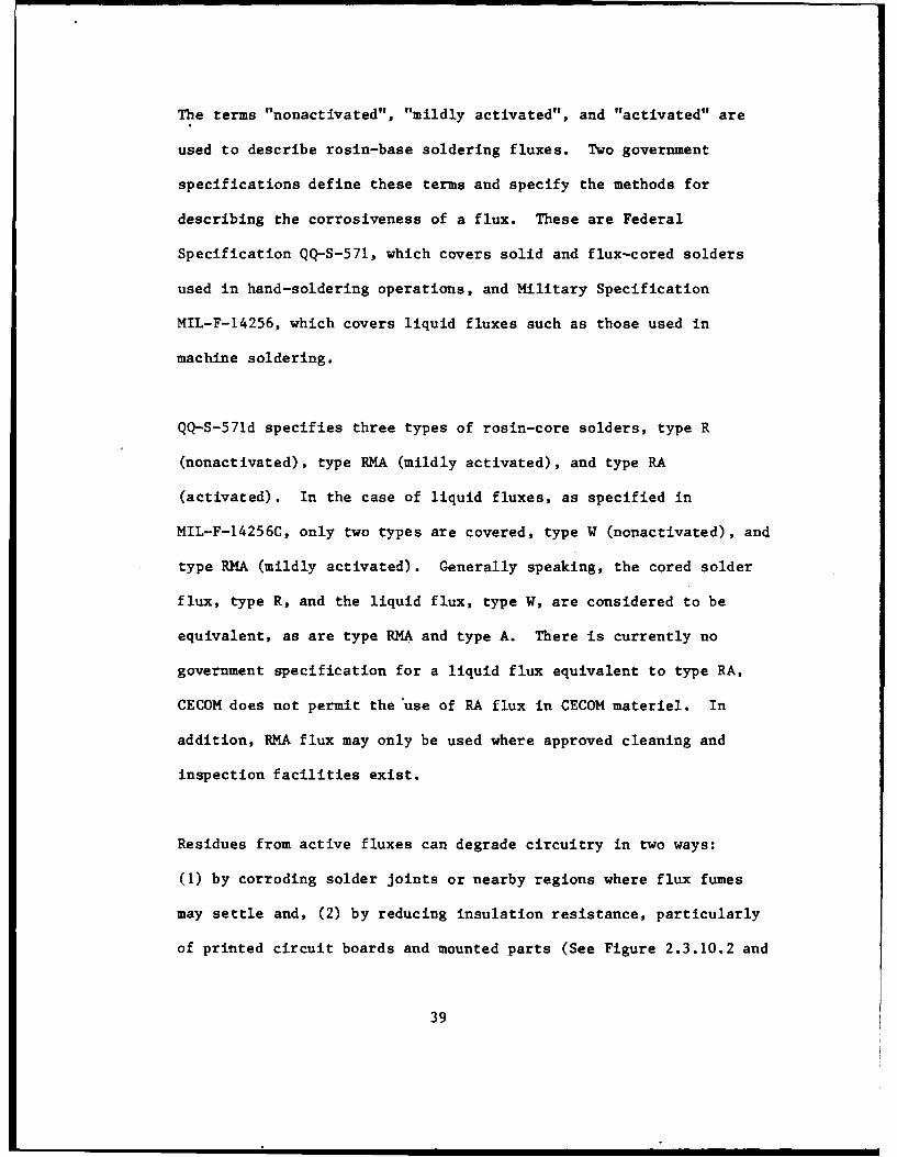
of printed circuit boards and mounted parts (See Figure 2.3.10.2 and
39
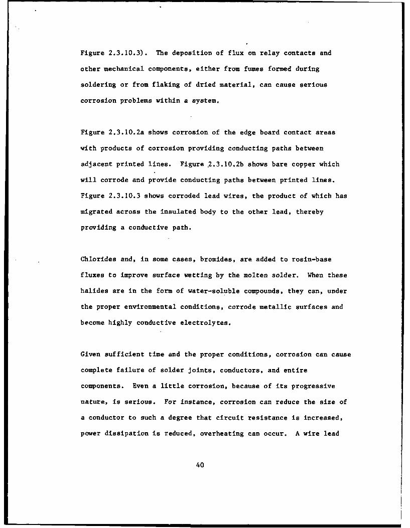
Figure 2.3.10.3). The deposition of flux on relay contacts and
other mechanical components, either from fumes formed during
soldering or from flaking of dried material, can cause serious
corrosion problems within a system.
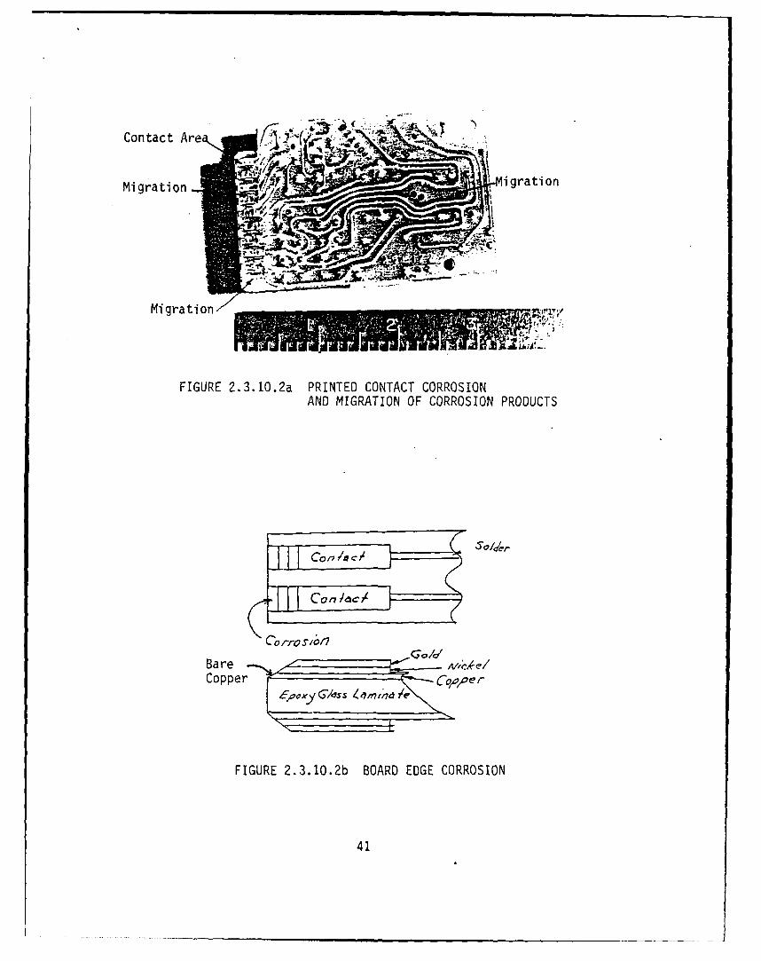
Figure 2.3.10.2a shows corrosion of the edge board contact areas
with products of corrosion providing conducting paths between
adjacent printed lines. Figure 2.3.10.2b shows bare copper which
will corrode and provide conducting paths between printed lines.
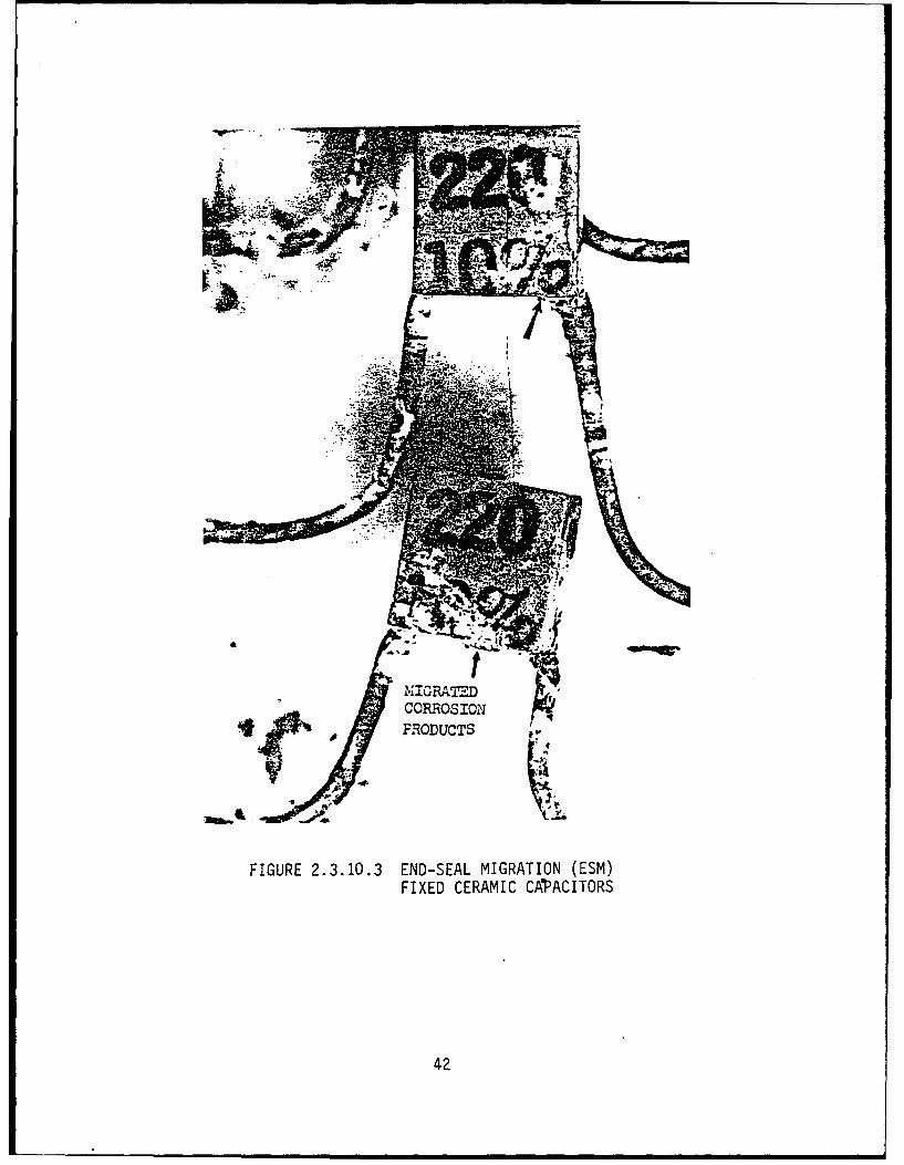
Figure 2.3.10.3 shows corroded lead wires, the product of which has
migrated across the insulated body to the other lead, thereby
providing a conductive path.
Chlorides and, in some cases, bromides, are added to rosin-base
fluxes to improve surface wetting by the molten solder. When these
halides are in the form of water-soluble compounds, they can, under
the proper environmental conditions, corrode metallic surfaces and
become highly conductive electrolytes.
Given sufficient time and the proper conditions, corrosion can cause
complete failure of solder joints, conductors, and entire
components. Even a little corrosion, because of its progressive
nature, is serious. For instance, corrosion can reduce the size of
a conductor to such a degree that circuit resistance is increased,
power dissipation is reduced, overheating can occur. A wire lead
40
Contact Are -
Migration irto
Migration
FIGURE 2..3.10.2a PRINTED CONTACT CORROSIONAND MIGRATION OF CORROSION PRODUCTS
con/a C/ oler
Con dc/
Bare
FIGURE 2.3.10.2b BOARD EDGE CORROSION
41
MIGRATEDCORROSION11
PRODUCTS
FIGURE 2.3.10.3 END-SEAL MIGRATION (ESM)FIXED CERAMIC CAPACITORS
42
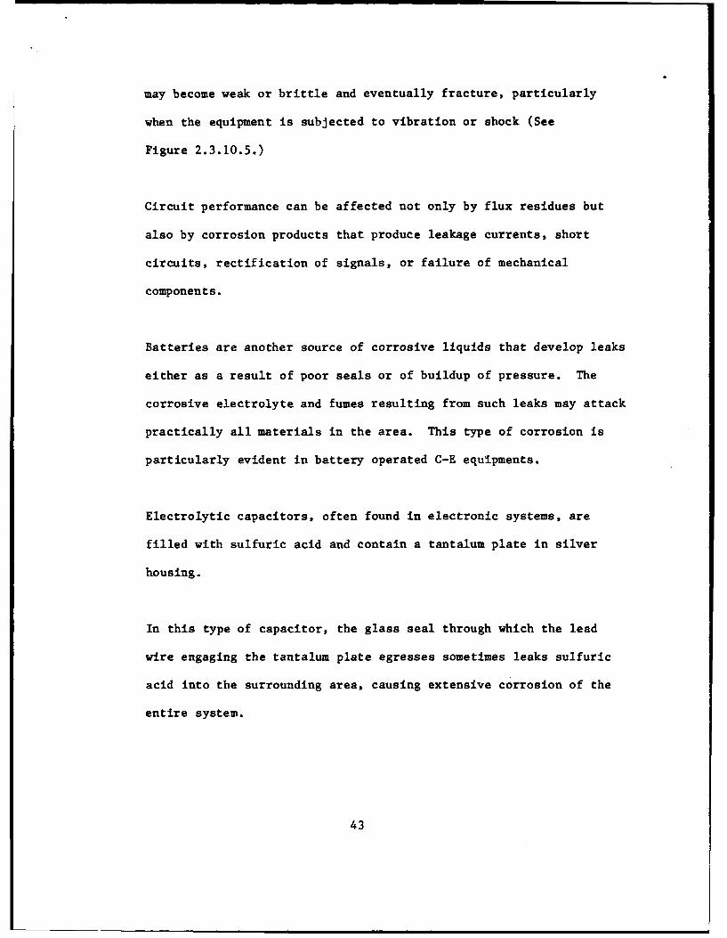
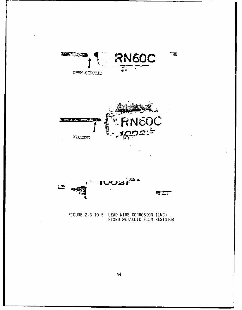
may become weak or brittle and eventually fracture, particularly
when the equipment is subjected to vibration or shock (See
Figure 2.3.10.5.)
Circuit performance can be affected not only by flux residues but
also by corrosion products that produce leakage currents, short
circuits, rectification of signals, or failure of mechanical
components.
Batteries are another source of corrosive liquids that develop leaks
either as a result of poor seals or of buildup of pressure. The
corrosive electrolyte and fumes resulting from such leaks may attack
practically all materials in the area. This type of corrosion is
particularly evident in battery operated C-E equipments.
Electrolytic capacitors, often found in electronic systems, are
filled with sulfuric acid and contain a tantalum plate in silver
housing.
In this type of capacitor, the glass seal through which the lead
wire engaging the tantalum plate egresses sometimes leaks sulfuric
acid into the surrounding area, causing extensive corrosion of the
entire system.
43
*460Co I- -~~r - "
K -,
FIGURE 2.3.10.5 LEAD WIRE CORROSION (LWC)FIXED METALLIC FILM RESISTOR
44
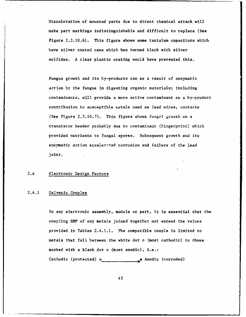
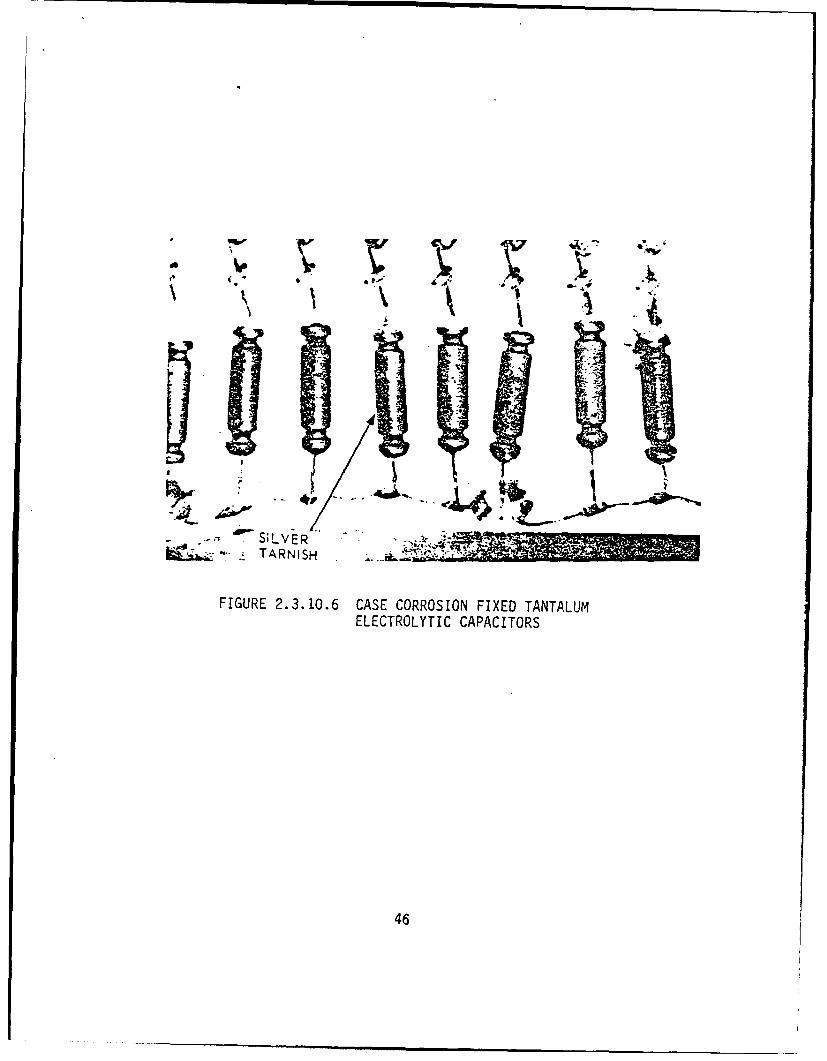
Discoloration of mounted parts due to direct chemical attack will
make part markings indistinguishable and difficult to replace (See
Figure 2.3.10.6). This figure shows some tantalum capacitors which
have silver coated case which has turned black with silver
sulfides. A clear plastic coating would have prevented this.
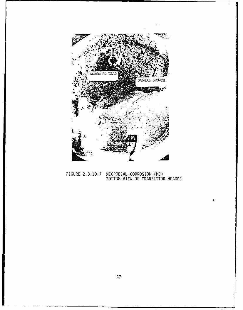
Fungus growth and its by-products can as a result of enzymatic
action by the fungus in digesting organic materials; including
contaminants, will provide a more active contaminant as a by-product
contribution to susceptible metals used as lead wires, contacts
(See Figure 2.3.10.7). This figure shows fungel growth on a
transistor header probably due to contaminant (fingerprint) which
provided nutrients to fungal spores. Subsequent growth and its
enzymatic action accelernted corrosion and failure of the lead
joint.
2.4 Electronic Design Factors
2.4.1 Galvanic Couples
In any electronic assembly, module or part, it is essential that the
coupling EMF of any metals joined together not exceed the values
provided in Tables 2.4.1.1. The compatible couple is limited to
metals that fall between the white dot o (most cathodic) to those
marked with a black dot o (most anodic), i.e.:
Cathodic (protected) o_ _ _ Anodic (corroded)
45
low
Ar S;LVER" .. ,., .- TARNISH
FIGURE 2.3.10.6 CASE CORROSION FIXED TANTALUMELECTROLYTIC CAPACITORS
46
Y. 4
* COM~fO=~LA
MIL AR'eT
FIGURE 2.3.10.7 MICROBIAL CORROSION (MC)BOTTOM VIEW OF TRANSISTOR HEADER
47
Whenever it is unavoidable, the contact should then be cleaned
thoroughly to remove any trace of a contaminant and that the couple
be sealed to keep out moisture and contaminants. The use of
magnesium and lithium or any compounds of such extreme anodic
nature, used because of weight gains obtainable with these metals,
should be pursued only when sufficient preventative measures have
been provided. In all couples, small contact areas should be
avoided, since small contact areas concentrate the corrosion rate in
a small area, making it prone to early failure. It is also
possible, in certain designs, to use isolating barrier shims or
washers in between adjoining metals. This reduces the EMF potential
between adjacent metals in contact.
In the design of complex assemblies, careful consideration should be
given to which metal and/or its alloy, should be coupled together.
The following guides, Tables 2.4.1.1, 2.4.1.2, can be helpful, but
it is recommended that a humidity and/or Salt fog test be conducted
during development to confirm that the couple, and the application
process as protected, is usable without incurring corrosion.
The rate at which the corrosion proceeds depends on the amount of
current generated within the galvanic cell. The amount of current,
in turn depends on several factors: (1) the existing electrode
potentials, (2) the ratio of the anode and cathode areas, and (3)
the polarization of the electrodes.
48
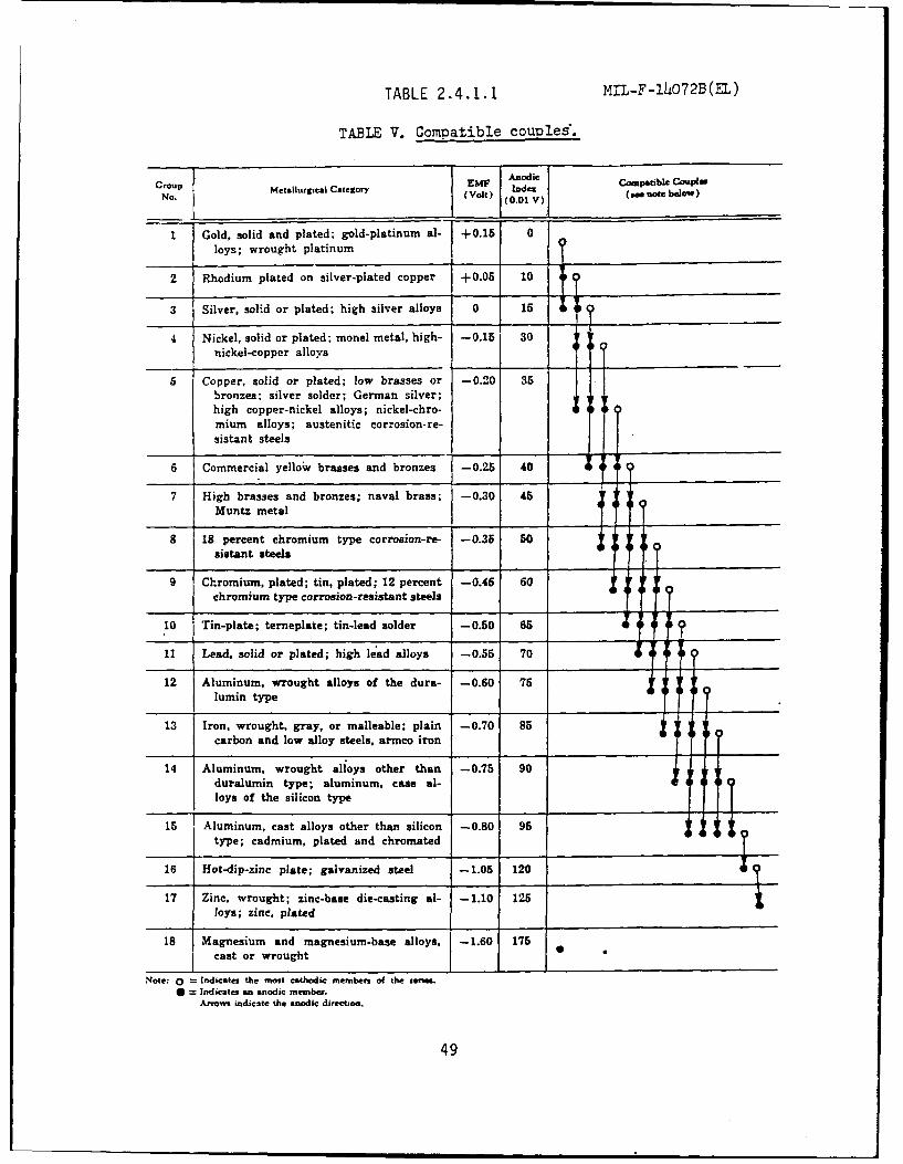
TABLE 2.4.1.1 ML-F-14072B(EL)
TABLE V. Compatible couDles.
Croup Metalurl Category EM nd compatible Coule
No. M (Volt) I.eV (am note below)(0.01 V)
1 Gold, solid and plated; gold-platinum al- ±0.15loys; wrought platinum ?+-
2 Rhodium plated on silver-plated copper +0.05 10
3 Silver. solid or plated; high silver alloys 0 15
4 Nickel, solid or plated; monel metal, high- -0.15 30nickel-copper
alloys
5 Copper, solid or plated; low brasses or -0.20 35bronzes; silver solder; German silver;high copper-nickel alloys; nickel-chro- :10mium alloys; austenitic corrosion-re-sistant steels
6 Commercial yellow brasses and bronzes -0.25 40 f?
7 High brasses and bronzes; naval brass; -0.30 45Muntz metal
8 18 percent chromium type corrosion-re- -0.35 50sistant steels
9 Chromium, plated; tin, plated; 12 percent -0.46 60chromium type corrosion -resistant steels I
10 Tin-plate; terneplate; tin-lead solder -0.50 65 f O
11 Lead, solid or plated; high lead alloys -0.55 70 f f f
12 Aluminum, wrought alloys of the dura- -0.60 75lumin type I
13 Iron, wrought, gray, or malleable; plain -0.70 85carbon and low alloy steels, armco iron
14 Aluminum, wrought alloys other than -0.75 90duralumin type; aluminum, case al-loys of the silicon type
15 Aluminum, cast alloys other than silicon -0.80 95 4,
type; cadmium, plated and chromated
16 Hot-dip-zinc plate; galvanized steel -1.05 120
17 Zinc, wrought; zinc-base die-casting al- -1.10 125foys; zinc, plated
18 Magnesium and magnesium-base alloys, -1.60 175cast or wrought
Note: 0 =indicates the most cathodic members of the sernm.S = Indicates an anodic member.
Arrows indicate the anodic directios.
49
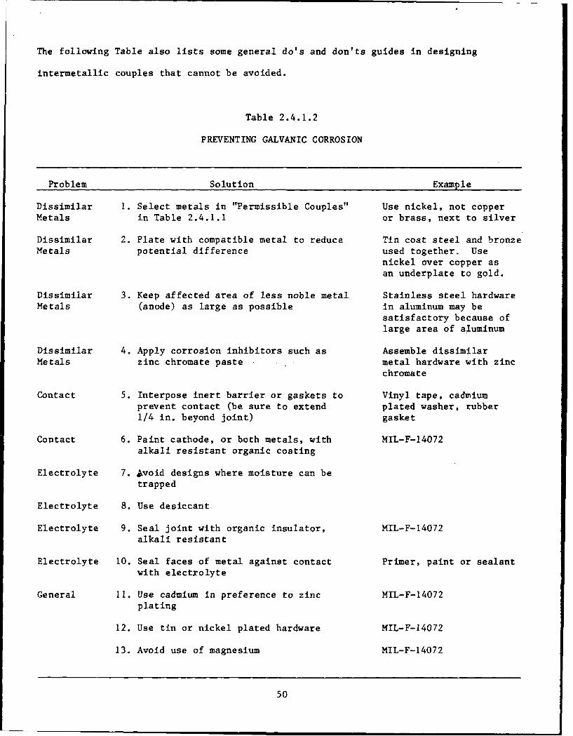
The following Table also lists some general do's and don'ts guides in designing
intermetallic couples that cannot be avoided.
Table 2.4.1.2
PREVENTING GALVANIC CORROSION
Problem Solution Example
Dissimilar 1. Select metals in "Permissible Couples" Use nickel, not copperMetals in Table 2.4.1.1 or brass, next to silver
Dissimilar 2. Plate with compatible metal to reduce Tin coat steel and bronzeMetals potential difference used together. Use
nickel over copper asan underplate to gold.
Dissimilar 3. Keep affected area of less noble metal Stainless steel hardwareMetals (anode) as large as possible in aluminum may be
satisfactory because oflarge area of aluminum
Dissimilar 4. Apply corrosion inhibitors such as Assemble dissimilarMetals zinc chromate paste metal hardware with zinc
chromate
Contact 5. Interpose inert barrier or gaskets to Vinyl tape, cadmiumprevent contact (be sure to extend plated washer, rubber1/4 in. beyond joint) gasket
Contact 6. Paint cathode, or both metals, with MIL-F-14072alkali resistant organic coating
Electrolyte 7. avoid designs where moisture can betrapped
Electrolyte 8. Use desiccant
Electrolyte 9. Seal joint with organic insulator, MIL-F-14072alkali resistant
Electrolyte 10. Seal faces of metal against contact Primer, paint or sealantwith electrolyte
General II. Use cadmium in preference to zinc MIL-F-14072plating
12. Use tin or nickel plated hardware NIL-F-14072
13. Avoid use of magnesium MIL-F-14072
50
A guide to finishing intermetallic couples is contained in para 3.13
of MIL-F-14072. It was developed as a guide for use in CECOM
materiel with consideration to many types of couples that can
occur. Because of the many variables that can occur and affect
corrosion possibilities, an environmental test should finally be
applied to assure that the design is corrosion resistant. The guide
is quoted in it entirety to provide maximum coverage of all galvanic
couple situations, as follows:
Beginning of quote:
"MIL-F-14072, Para 3.13 Intermetallic-couples. The finishing of
metallic areas to be placed in contact presents a special problem,
since intermetallic contact of dissimilar metals results in
electrolytic couples which promote corrosion through galvanic
action. Table V (Table 2.4.1.1 of this guide) shall be used in
determining the need or degree of protection to be applied to couple
members depending on the relative position of the coupled members in
the galvanic series. Table V shows metals and alloys (or plates) by
groups which have common electro-motive forces (EMF) within 0.05
volt when coupled with a saturated calomel electrode in seawater at
ordinary room temperatures. All members of a group regardless of
metallurgical similarity or dissimilarity are considered
compatible. Compatible couples between groups have been specified
in Table V based on a potential difference of 0.25 volt maximum.
51
Permissible couple series are shown in Table V by the graphs at the
right. Members of groups connected by lines will form permissible
couples. An "o" indicates the most cathodic member of each series,
"1" an anodic member, the arrow the anodic direction, Table V shows,
in addition the EMF against a calomel electrode, a derived "anodic
index" with Group I (gold, etc.) as 0 and Group 18 (magnesium, etc.)
as 175. Subtraction of one group anodic index from another gives
the EMF difference in hundredths of a volt. To provide the
corrosion protection required in ground electronic equipment,
intermetallic couples should be restricted, where possible, to those
permitted in Table V which have minimal tendencies to interact
galvanically.
3.13.1 Use of compatible couples. The following should be
considered in the selection and application of compatible couples:
a. Passivated coatings. For couple selection, passivated coatings
specified herein shall be ignored and only the plating or basis
metal considered. For example, all chromate or phosphate
treatments of zinc or cadmium specified in Tables II and III
shall be ignored in making couple selections and only zinc or
cadmium considered as acting in galvanic corrosion. Hard
anodic films on aluminum-base alloys are impervious
nonconductors and, therefore, contact may be made with any
dissimilar metal.
52
b. Surface area of contacting metals. In intermetallic couples,
the member with the higher anodic index is anodic to the member
with the lower anodic index and will be susceptible to
corrosion in the presence of an electrolytic medium. If the
surface area of the cathodic part is significantly greater than
that of the anodic part, the corrosive attack on the contact
area of the anodic part may be greatly intensified. Material
selection for intermetallic contact parts, therefore, should
establish the smaller part as the cathodic member of the
couple.
c. Platings. For couple selection only the contacting metallic
surfaces shall be considered for compatibility. For example,
when a plated part is intended for assembly with aluminum, the
compatibility of the plating, not the basis metal, with
aluminum shall be considered. Likewise, when two plated parts
are intended to be coupled, the compatibility of the platings,
not the basis metal, is to be considered.
3.13.2 Exceptions to Table V. The following exceptions apply to
the selection of compatible couples in accordance with Table V:
a. Special service conditions. Table V is for use when part and
equipment will be exposed to the military service conditions of
ground electronic equipment. For special conditions or
53
considerations, Table V may not be applicable. Such
considerations may include such factors as temperature
differences between parts, plating thicknesses, longevities,
polarity reversals, multiple contacts, etc. For instance, zinc
may become cathodic to iron in hot tap-water, and tin anodic to
iron in tap-water at ordinary temperatures. Both of these, as
isolated cases, vary from the general experience reflected by
the compatibility graphs of Table V. In isolated cases, where
couples are not exposed to weather or to salt-laden air but are
subject to wide temperature and humidity variation with
probable accompanying condensation, restriction of couple
members to those shown in Table V might serve to provide part
life abnormally longer than the functional requirements of the
-equipment. In such cases, finish needs may be met by extending
the anodic index differences to 50. Generally, under special
conditions, couple selection should be governed by experience
with such special conditions.
b. Sealed meL..ers. The requirements specified above do not apply
to intermetallic contact members which, in a clean and dry
condition, are permanently sealed in noncorrosive embedding or
encapsulating materials, or hermetically sealed containers that
are impervious to atmospheric conditions.
54
c. Magnesium. Table V does not permit intermetallic contact
between magnesium and any other metal. If the use of magnesium
in contact with a dissimilar metal is required, the metals
shall be separated by a tape in accordance with MIL-T-23142.
The tape shall extend at least 0.32cm (1/8 inch) beyond the
periphery of the Joint. The use of cloth supported tapes is
prohibited.
d. Fasteners for magnesium. Although not allowed by Table V, the
use of aluminum alloy 5056-H32 rivets and aluminum alloys 5052,
5056, 6053, and 6063 washers and shims will be allowed for
assembly of magnesium alloy members. Bolts and nuts will be
restricted to 6061 aluminum alloy, anodized, and dipped in zinc
chromate primer conforming to TT-P-1757 prior to insertion.
3.14 Finish selection. Unless otherwise allowed by the contracting
officer, any finish applied to equipment shall be one of those
specified by Tables I, II or III. Insofar as possible, selection of
finishes for any particular application shall be made in accordance
with Table VI. Any restrictive conditions applicable to finish
selection not appearing in Table VI must be considered prior to
making a choice of finish. In this connection, it may be noted that
Tables I through IV Zontain finish selection requirements applicable
to particular finishes. Paragraphs 3.14.1, 3.14.2 and 3.14.3
regarding finishes covered by this document, apply to finish
selection and shall be used in conjunction with Table VI.
55
It should be noted that Table V of MIL-F-14672 is a design and
finishing guide which lists allowable couples and it is different
than Tables which simply list metals in order of EMF potentials
depending on what type of electrolyte was used."
End of Quote:
Using The Tables
When consulting Table 2.4.1.1 the following factors should be
considered:
a. The surface metal is the one involved, whether it be solid
plated, dipped, sprayed, or laminated.
b. Graphite acts like a metal, and forms galvanic cells.
c. Different alloys of the same metal (especially aluminum and
copper) can form a galvanic cell. The Table will show some to
be acceptable.
In a galvanic corrosion, the relative area of the anodic (attacked)
and the cathodic (more noble) metal is of great importance. When
the anodic area is large, the rate of corrosion is less rapid than
when the area is small. The potential voltage differential is not
56
changed, but since the current is spread over a larger area, the
current density is lower. The areas considered are only those
wetted by the electrolyte. If an assembly is totally immersed, all
the metal is part of the galvanic cell. But if moisture is present
only in local pockets, as from condensation around a joint, only the
wet surfaces are part of the cell. The influence of area explains
why steel nuts and bolts may be used satisfactorily in a large
aluminum structure, while aluminum hardware on a steel sheet would
be quickly corroded away.
57
changed, but since the current is spread over a larger area, the
current density is lower. The areas considered are only those
wetted by the electrolyte. If an assembly is totally immersed, all
the metal is part of the galvanic cell. But if moisture is present
only In local pockets, as from condensation around a joint, only the
wet surfaces are part of the cell. The influence of area explains
why steel nuts and bolts may be used satisfactorily in a large
aluminum structure, while aluminum hardware on a steel sheet would
be quickly corroded away.
The current flow and effective potential difference between
dissimilar metals in an electrolyte may also be reduced by
polarization. Polarization may occur at the anode as a result of
the accumulation of corrosion products, or at the cathode as a
result of the accumulation of hydrogen bubbles at the cathode
surface. In either case, the result is a decrease in
electrochemical action. The deposition of hydrogen is the more
influential deterrent and may produce a strong barrier to galvanic
corrosion.
Corrosion is generally accelerated by rising temperature. An
increase in temperature results in increased conductivity of the
electrolyte and an increase in the solubility and diffusion rate of
normally protective corrosion products. Cathodic depolarization by
dissolved oxygen increases as temperatures rise because oxygen is
58
diffused more rapidly at higher temperatures. On the other hand, at
800C or above, oxygen becomes less soluble and the corrosion rate
decreases.
Anything that reduces the difference in potential between the metals
involved, prevents metal-to-metal contact, or removes the
electrolyte, prevents galvanic corrosion. Proper control of
relative area minimizes attack. As Table 2.4.1 indicates, there are
ways to preclude corrosion even when dissimilar metals must be used
since it is not the inherent corrosion resistance of a metal that
matters, but the difference in potential between it and those it
contacts. The greater the difference in potential between two
metals, the more the care that must be taken to protect the metals
from corrosion.
2.4.2 Contacts
2.4.2.1 General
Contacts are the most unreliable functions in electronics designs.
The recent development of solid state switching has minimized this
somewhat, but connector pins and edge board connections, make and
break types still contribute heavily to failures; especially
corrosion types. Contacts of parts used on front panels are
engineered to do very special tasks, and their contacts are designed
59
for long and reliable life. Therefore, they should be of MIL-STD
hi-rel quality. Troubles occur with printed circuit board contacts
which are of either edge type or pin and socket designs. Many
contact metals, such as printed copper or extruded copper alloy
pins, will oxidize in storage. To avoid cleaning them, they are
usually gold plated to avoid tarnishing. Due to the high price of
gold, plating can be much thinner than required resulting in
porosity of the gold plating. With rough or unpolished surfaces,
the deposited gold is more porous allowing the copper alloy to
migrate through the pinholes and become copper oxide (black, an
insulator). For prevention, it is necessary to initially deposit 50
microinches of electroless nickel under the 50 microinches of gold
to prevent corrosion and open circuit contacts.
2.4.2.2 Pin and SocKet Corrosion
The use of discrete daughter boards, which plug into motherboards,
is made possible by the use of multipin module connectors to
accommodate interconnections from module to modulg. Typical pins
are illustrated in Figure 3.4.2.
Each module may have as many as 20 to 250 pins. The average number
of pins per board is 100 and there may be an average of 5000 boards
in an average size communication center or a total of 500,000
connections. It is an accepted fact that the most unreliable type
60
connection in electrical and electronic circuitry can be the
dry-circuit, sliding make-and-break contact, such as is found in
these connectors. Failure rates of 01 X 10-6 failures/hour have
2been observed for each connection. For a 500,000 connection
system, unless good quality is obtained, one failure per day can be
expected. While there are many mechanical type failures, usually
dirty, oxidized, or corroded surfaces are the main causes of
failures. All pins and receptacles used today are gold plated.
Because of surface roughness, which is difficult to minimize on pins
of the sizes in usage, pinholes occur in the gold and resultant
black copper oxides or green copper chlorides will coat the contact
area as is shown in Figure 2.3.1.2. Similar type failures are shown
on gold plated pins with a silver barrier underplating as is shown
in Figure 2.3.1.3.
Many current specifications call for soft gold, on hard gold, over
nickel plated beryllium copper. The soft gold provides a
lubricating easily cleaned and wiping contact. Salt fog exposure
and nitric acid dips are used as a test for gold porosity. Long
term field tests after initial wear of gold surface are needed to
provide long term corrosion and contact resistance data. Quality
control to assure nickel underplating and pore-free gold plating
usually assures reliable connection.
61
2.4.3 Joining, Soldering, Bonding
Joining, soldering and bonding are used in various assembly
processes in the following categories:
2.4.3.1 Insulated wires, point-to-point
Current technology of miniaturization has diminished the use of such
wiring. In large Command, Control Centers (CCC) systems, these are
applied with wire wrap, which is tool applied without soldering.
Hand soldering usually has process control problems and may vary in
quality as described below.
2.4.3.2 Thermobondings
Thermobondings are usually applied in hermetically sealed
miniaturized packages and may involve excessive galvanic couples
and/or thermal stresses. The designer depends on the clean
hermetically sealed container to keep out moisture and electrolytic
contaminants. Depending on the quality of assembly, degree of
cleanliness and effectiveness of seal, corrosion and debonding of
the joint can occur with failures. Controlling quality per
MIL-C-38510 and with ESS screening, faulty or poor quality bonds can
be screened.
62
2.4.3.3 Soldering
All quality soldering requires clean surfaces to be soldered, the
proper heat applied and cleaning after to remove residual fluxes.
For printed wiring assemblies, contaminates can be added during
etching and flow or wave soldering. Since it is expensive to clean
assemblies, or to use gold plating, many manufacturers may resort to
using activated fluxes, which are controlled by MIL-F-14256, which
does not permit use of type RA fluxes in CECOM equipments. Even
with type RMA fluxes, cleaning after soldering must be rigorous. A
cleanliness test for PWAs is required in MIL-P-28809. Finally, a
protective conformal coating per MIL-I-46058 must be applied to
shield the cleaned printed circuit board assembly from industrial
and natural contaminants. Without the cleaning and coating
protection, experience has shown that corrosion of the copper land
areas, printed conductor lines and part leads can corrode and cause
shorts and/or open circuits. For parts with poorly cleaned surfaces
and use of a nonactivated flux, solder joints can be defective with
poor process control. With each contract, and contractor, the
soldering process must be controlled to assure good soldering joints
while at the same time preventing corrosion which can occur
eventually. Once established, this process must be continuously
monitored to assure quality joints with no possibilities of
corrosion failures occurring at later periods. The Institute of
63
Printed Circuits has published many handbooks on Assembly and
Joining Techniques to provide guidelines of such processes. See
Reference Number 14.
2.4.4 Antennas
Because of their exposure, and the need to use light weight metals
such as high strength aluminums, antennas can be subject to
extensive corrosion. In some cases, magnesium was used with
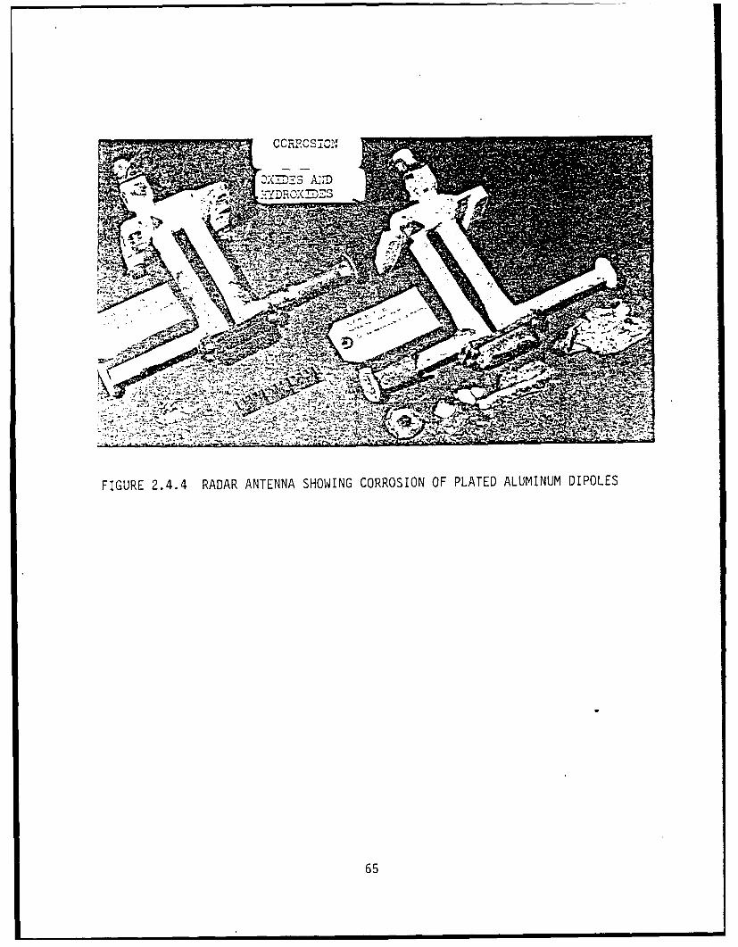
resulting higher corrosion rates and failures. Figure 2.4.4 shows
excessive corrosion of plated aluminum dipoles. Any dissimilar
metal attached to a magnesium or aluminum structure can cause severe
galvanic corrosion if surfaces and junctions are not adequately
prepared and protected. Some very severe corrosion failures for the
MPQ-4, 5, Firefinder, PPS-5 and PRC-77 have shown that the antenna
designs needed improvement. Corroded structures are inefficient
dipoles and will destruct in severe weather. All couples should be
minimized and all surfaces adequately painted. Whip antennas for
portable and/or manpack radios must be lightweight, flexible, but
also rugged to avoid breakage. Applied finishes receive severe
abrasion with resulting corrosion and breakage. It is best to use
inherently resistant aluminum alloys which are surface treated to
avoid reflective surfaces.
64
• , k-YDRO;M ES
,.
FIGURE 2.4.4 RADAR ANTENNA SHOWING CORROSION OF PLATED ALUMINUM DIPOLES
65
2.4.5 Connectors
These are especially prone to corrosion because of the same porous
gold plating on copper alloy pins mentioned in para 2.4.2 "Contacts"
above and the fact the connector can be in an exposed use
situation. The constant plugging and unplugging of connectors,
especially multipin types causes high wear and loss of gold plating
with copper corrosion occurring. Again, it is necessary to assure
that a .05 mil electroless nickel plating is applied as an
underplating to gold in order to prevent pinhole corrosion,
migration of copper and yet provide good wear properties. The
corrosion of the connectors shells can cause corrosion products to
migrate over the insulator insert and cause shorts. The use of
attached protective boots and covers, with constant cleaning will
prolong the useful life of connectors.
2.4.6 Waveguides
These are subject to corrosion and failure due to high humidities
and contamination present inside the waveguide interiors. Flanges
are welded to straight or curved sections, and without adequate
cleaning, welding or brazinQ flux remains as a contaminant. For
good waveguide alignment, a flexible section is usually located next
66
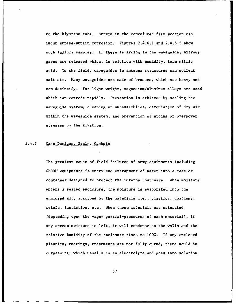
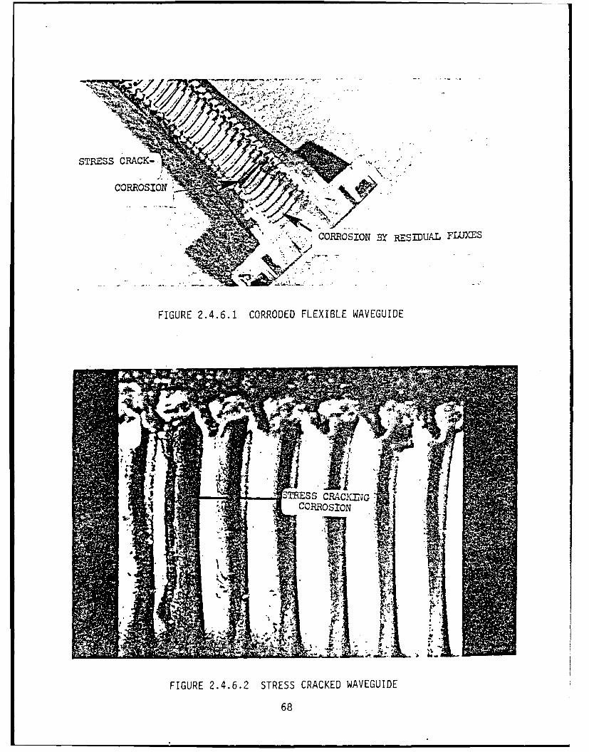
to the klystron tube. Strain in the convoluted flex section can
incur stress-strain corrosion. Figures 2.4.6.1 and 2.4.6.2 show
such failure samples. If there is arcing in the waveguide, nitrous
gases are released which, in solution with humidity, form nitric
acid. In the field, waveguides in antenna structures can collect
salt air. Many waveguides are made of brasses, which are heavy and
can dezincify. For light weight, magnesium/aluminum alloys are used
which can corrode rapidly. Prevention is achieved by sealing the
waveguide system, cleaning of subassemblies, circulation of dry air
within the waveguide system, and prevention of arcing or overpower
stresses by the klystron.
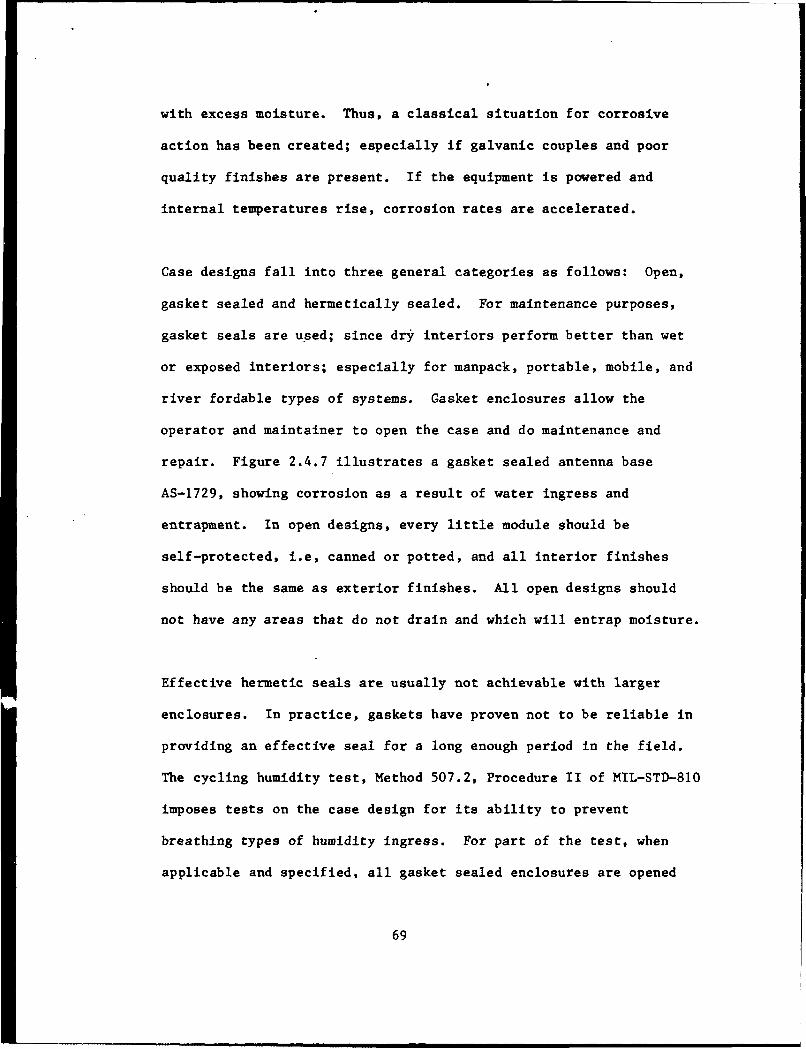
2.4.7 Case Designs, Seals, Gaskets
The greatest cause of field failures of Army equipments including
CECOM equipments is entry and entrapment of water into a case or
container designed to protect the internal hardware. When moisture
enters a sealed enclosure, the moisture is evaporated into the
enclosed air, absorbed by the materials i.e., plastics, coatings,
metals, insulation, etc. When these materials are saturated
(depending upon the vapor partial-pressures of each material), if
any excess moisture is left, it will condense on the walls and the
relative humidity of the enclosure rises to 100%. If any enclosed
plastics, coatings, treatments are not fully cured, there would be
outgassing, which usually is an electrolyte and goes into solution
67
STRE-SS CRACK-
CORROSION BY RE SDUAL FLUY-ES
FIGURE 2.4.6.1 CORRODED FLEXIBLE WAVEGUIDE
7TES .o.; r-;
FIGURE 2.4.6.2 STRESS CRACKED WAVEGUIDE
68
with excess moisture. Thus, a classical situation for corrosive
action has been created; especially if galvanic couples and poor
quality finishes are present. If the equipment is powered and
internal temperatures rise, corrosion rates are accelerated.
Case designs fall into three general categories as follows: Open,
gasket sealed and hermetically sealed. For maintenance purposes,
gasket seals are used; since dry interiors perform better than wet
or exposed interiors; especially for manpack, portable, mobile, and
river fordable types of systems. Gasket enclosures allow the
operator and maintainer to open the case and do maintenance and
repair. Figure 2.4.7 illustrates a gasket sealed antenna base
AS-1729, showing corrosion as a result of water ingress and
entrapment. In open designs, every little module should be
self-protected, i.e, canned or potted, and all interior finishes
should be the same as exterior finishes. All open designs should
not have any areas that do not drain and which will entrap moisture.
Effective hermetic seals are usually not achievable with larger
enclosures. In practice, gaskets have proven not to be reliable in
providing an effective seal for a long enough period in the field.
The cycling humidity test, Method 507.2, Procedure II of MIL-STD-810
imposes tests on the case design for its ability to prevent
breathing types of humidity ingress. For part of the test, when
applicable and specified, all gasket sealed enclosures are opened
69
GASKET Corrosion
c
Case Removed
FIGURE 2.4.7 CORROSION DUE TO MOISTURE ENTRY IN GASKET SEALED ENCLOSURECORROSION OF ANTENNA BASE MOUNT DUE TO MOISTURE ENTRY INTOGASKET SEALED ENCLOSURE
70
and the interior is exposed to full humidity cycling. Method 512.2
Leakage (Immersion) tests for leakage through all shafts, switch and
gasket seals. With continued use, gaskets lose their effectiveness
unless replaced periodically. The larger the gasket, the less the
effective life. In effect, gasket sealed interiors cannot be relied
upon to provide a dry interior unless critical portions of the
interior circuitry are self-protected and the interior are
periodically opened, cleaned, dried and the gasket replaced if
defective. EMI gaskets because of their composition, i.e., filled
with metallic meshes, usually have a shorter life and may be subject
to corrosion.
2.4.8 Case Hardware
Handles, clamps, case materials, mounting hardware, etc. receive
severe mechanical wear and damage. Special abrasion resistant epoxy
enamels should be used per MIL-F-14072 "Finishes For Ground
Electronic Equipment".
2.5 Manufacturing Processes
During production, control of assembly and material processes play a
major role in the equipment quality. Most of these are described in
MIL-P-11268, "Parts, Materials & Processes Used in Electronic
71
Equipment", MIL-STD-454 "Standard General Requirements For
Electronic Equipment" and MIL-Q-9858, "Quality Program
Requirements". The number and types of processes that apply are
numerous, but the following highlights are those which have a
considerable impact on corrosion resistance directly.
2.5.1 Cleanliness
Industrial contaminants can provide the electrolyte needed to
complete the corrosion cell or cause direct chemical corrosion
action. Periodic cleaning, covered transport boxes to transport
items from station to station, clean tools, air venting of
contaminated areas, minimum human handling, etc. all must be
controlled to assure a minimum of contamination. For critical
portions of circuitry, i.e., printed circuit board assembly,
contacts, etc., semi-clean room handling and air-conditioned parts
storage would be necessary. Figure 2.5.1 illustrates an automatic
production line cleanliness tester. The cleanliness tester
automatically, cleans and tests the cleanliness of the cleaning
solution. If the solution gets too dirty or unclean, as required,
the line stops and adjustments must be made.
2.5.2 Soldering Fluxes
The use of fluxes is controlled by MIL-F-14256 "Flux, Soldering,
Liquid (Rosin Base) and Requirement 5 of MIL-STD-454. The use of
72
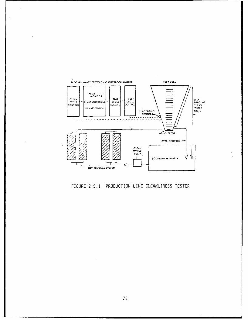
PRCGRAMMAAEZ tLUCTRONEC LNTERLOCK SYS~TM TES7 CZLI.
CUaAN 7E7 OSCLF-eL LUMl: CONTROLS -YL -C- PURGNllG
CCNTRCL RECOUC CU2Tr;a 7 ~ A
[OM RCMOVAL SYSTEM
FIGURE 2.5.1 PRODUCTION LINE CLEANLINESS TESTER
73
activated fluxes is not permitted and even the use of RMA flux
requires through cleaning after soldering.
2.5.3 Finishes, Platings, Coatings
There is a tendency by contractors to provide military hardware with
commercial grade finishes. Careful incoming inspections should
establish and assure acceptable military grade finishes as needed
per MIL-F-14072. During assembly and processing, finishes may be
scratched or damaged by sharp tools, machine handling, etc. These
breaks in the finish coating can initiate corrosion which can spread
in time. Epoxy type coatings per MIL-F-14072 have optimum scratch
resistance. Platings should also comply with MIL-F-14072. Before
production, samples of platings and coatings should be inspected and
salt fog tested to establish quality acceptance criteria. Periodic
sampling of fabricated and plated or coated parts should be sampled
per MIL-STD-105 and tested again to assure quality. Good quality
finishes play a major role in preventing direct chemical corrosion.
2.5.4 Repair/Fixes
During production certain repairs and fixes are processed. Such
repairs require removal of coatings, resoldering touch-ups or all
types of reworking. Many times the quality of repair is so poor or
haphazard that a potential corrosion failure is incurred. Such
examples are:
74
An open circuit is found on a printed circuit board assembly and a
repair is made by scraping off the conformal coating and hand
soldering a repair; possibly with activated flux. To avoid a
refailure, the soldering should be done with an RMA flux, which is
thoroughly cleaned to remove residual flux and the repair recoated
with an approved conformal coat.
A deep scratch on the case is repaired by touch-up To avoid
failure, the scratch should be sanded, cleaned, dried, and recoated
with an undercoat and a final epoxy coat, or the same finishes
should be reapplied as originally applied.
In many cases, after repair, a reinspection is not performed.
Actually, a reinspection should establish that the fix has not
degraded the quality of the finish.
2.6 Corrosion Resistance Testing
2.6.1 Panel Testing
The testing of a plated or coated flat panel is usually done to
evaluate the effectivity of a paint, coating or plating system
(surface treatment and two coats or platings). Test panels of metal
are coated and exposed to a Salt Fog Test per Method 509.2,
MIL-STD-810 for 48 hours or more to establish the quality of
75
protection. A flat smooth panel is an ideal basis metal for
evaluating and comparing various types of paintings or platings.
Such results may be misleading as they would not be applicable to a
complex electronic item. Shapes and sizes with varying smoothness
of surface will affect results profoundly. In most cases, it is
necessary to coat and expose the actual complex parts assembly to
cbtain a good test of the effectivity of the coating process
quality.
2.6.2 Corrosion Resistance Testing of Electronic Systems
For electronic systems/equipments, MIL-STD-810 lists five tests that
can be used to measure corrosion resistance effectivity. These are
as follows:
Method 506.2 Rain
Method 507.2 Humidity
Method 508.2 Fungus
Method 509.2 Salt Fog
Method 512.2 Leakage (Immersion)
Each of the above tests are usually included in Section 4 of any
equipment specification and are scheduled to be conducted in First
Article Test (FAT), preproduction, or initial production and
76
repeated periodically on a Group C lot-by-lot sampling. For
purposes of testing corrosion resistance, the following should be
used as a guide:
2.6.2.1 Rain Test
One of the purposes of the rain test is to determine if rain is
collected or is entrapped in any complete system enclosure. Such
entrapment would provide conditions for eventual initiation of
corrosion. Because of the short test duration, no corrosion would
be evident after the tests. If rain is entrapped or collected; this
shall be considered as a failure of the design and must be classed
as a deficiency requiring design improvement; even if .only for the
purposes of corrosion prevention. Rain tests are usually only
conducted on field exposed stand-alone equipments. LRUs and
equipments that are used in a shelterized facility, should not be
rain tested.
2.6.2.2 Humidity
Humidity can initiate some corrosion mechanisms but usually not
enough to cause any failure of electronic functions. If the paints,
coatings, or platings have not been applied properly, high humidity
and temperatures will cause them to peel, blister or scrape off
easily. Such corrosion will also not immediately affect the
77
operation and performance of the equipment. If a contaminant was
present, then corrosion will initiate sooner and progress rapidly.
Moving parts, even with initial corrosion, might bind. Contacts may
experience higher resistances. The equipment may still perform even
within specified levels. The important criteria is that initial
corrosion will always increase and not reverse. Consequently, any
initial corrosion should be cause for concern and failure of the
equipment under test. In these instances, failure analysis should
be thorough. The test can be extended for longer periods for
diagnostic purposes. No initial type of corrosion should ever be
dismissed as not significant.
2.6.2.3 Fungus
The main purpose of the Fungus Test is to determine if any organic
materials were used or-any contaminants were present which will
stpport the growth of fungus. Fungus car affect the properties of
organic materials by changing their molecular structure. The
by-products of enzymatic actions can provide an electrolyte which
can initiate and accelerate corrosion. A 28-day test as is
specified in Method 508.2, is not long enough to provide extensive
breakdown of material properties. Usually, longer periods of
exposure such as 90 days of exposure are required to effect damage.
Any initial or incipient corrosion noted by visual means after the
Fungus Test should also be cause for concern and failu :e of the
78
equipment under test. Fungus growth may appear as a corrosion
by-product. Usually, fungus growth will occur wherever organic
materials are present, whereas corrosion will occur only where
metals are present. Microscopic examination and chemical analysis
may be necessary to determine the difference.
2.6.2.4 Salt Fog
This test is currently used by commercial and industrial companies
to test for the protective effectiveness of applied finishes and
coatings on metal surfaces and also to compare effectiveness of
various types of finishes. Testing is usually accomplished on panel
specimens. It is the most corrosive of all the so-called
environmental tests. Applied to a C/E equipment, it will accelerate
corrosion rates more than any other environmental test listed. It
is a destructive test, rendering the C/E equipment under test not
eligible for repair or rehabilitation if extensive corrosion does
occur. While being the prime and most effective corrosion test,
this best does have many shortcomings; which tend to make
interpretation of results and application of failure criteria
difficult because of the following:
Because of the high concentration of salt 5 + I percent solution
which is used which is considerably higher than the natural sea mist
at marine areas. Corrosion rates can be less than that occurring in
the field.
79
There is a general misconception that the Salt Fog test simulates
marine type conditions. No such correlation has ever been
successfully established or reported.
Because of clogging, poorly mixed salt/water concenL&.Lions, uneven
distributions, salt impurities, and water impurities, the test is
not too reproducible.
Failure criteria for this test are mainly visual except for binding
of shafts and switches. Encrustation of salt deposits makes this
difficult. Washing to remove salt deposits will also remove water
soluble corrosion deposits.
Most corrosive deposits can be identified visually by the naked
eye. A four power amplification would help identify incipient
corrosion; especially at structures with metallic couples. Any
blistering, peeling or lifting of paints, coatings and/or platings
shall be noted as failures. All mechanical devices such as:
switches, contacts, adjustments, Pitches, hinges, should be checked
for binding, high contact resistance or corrosion products. No
electrical performance of the equipment; even after thorough
washing, should be required as meaningful or applicable.
80
2.6.2.5 Leakage Immersion
This test is conducted to detect gross leaks for the purpose of
determining the effectiveness of enclosed cases, either with gaskets
or hermetically sealed to protect the enclosed system hardware. It
is essential for manpack and portable equipments; especially units
that are forded through rivers or lakes or stored in marine or
tropical areas. When sufficient moisture leaks or enters such an
enclosure, 100% Relative Humidity is attained when all of the
enclosed mass is saturated with absorbed moisture; thus subjecting
the electronic hardware to a constant high humidity condition,
Moisture is continually leaked in but exits only under select
conditions. Gasketted enclosures are notorious leakers; especially
after the unit is opened and closed several times or the gasket
material becomes stiff and/or breaks with age.
The best pass/fail criteria is one that weighs the assembly before
and after immersion. Any excess moisture (+ x grams) weighed or
noted inside the enclosure after immersion; indicates the
possibility of leakage and moisture saturation inside the case.
After immersion, the enclosed case or container should be allowed to
dry for 24 hours, without opening the case, and then weighed. This
weight should be compared to a dry case or container befnre
immersion. Iny gain in weight should be a basis for failure of the
equipment under test.
81
3. Lessons Learned
The following are examples of corrosion problems which caused a
delay in programs, which were resolved by determining the failure
mechanisms and resulted in a fix. These are only typical examples
selected to show the pattern of corrosion occurrence, failure
analysis and get-well recommendations. In most instances, initial
failure reporting did not mention corrosion but only failure types
were reported, i.e., open circuit, failed part, etc. Only after
extensive failure analyses of the part, its application, and several
field trips was corrosion discovered as the root cause of failure
and an effective fix applied.
3.1 Waveguide Corrosion
TPQ-37: Extensive failures of the waveguide sections of the mortar
locator radar was being experienced with high replacements. The
flexible waveguide section next to the klystron tube was made of
accordion shaped brass alloy guides. The shaping of these guides
caused high stresses to exist at the outside loop of the guide.
Arcing from the klystron would deposit nitrous oxide in the air and
in solution with the moisture which entered the waveguide, it
created a nitric acid solution. This acid provided an electrolyte
tc cause stress corrosion of the waveguide convolutions. In
addition, there was extensive corrosion on the brass flanges due to
82
residual brazing fluxes. See Figures 2.4.6.1, 2.4.6.2. The problem
was cured by circulating dry air in the waveguide sections,
thoroughly cleaning the waveguide sections before assembly to remove
brazing fluxes and other contaminants, and annealing the flexible
waveguides after forming. The lesson learned was to remove all
welding and brazing fluxes during production and to circulate dry
air in the waveguide system during operation.
3.2 Antenna Corrosion
ASN-128 Doppler Navigator: The antenna section of the ASN-128 was
installed in the belly of the Blackhawk helicopter, which meant it
collected all the cleaning water during cleaning operations with
unknown detergent cleaning ingredients. This all collected in the
belly and seeped into the antenna section. Extensive corrosion
occurred to the magnesium waveguides and magnetic components. This
also occurred whenever the helicopter occasionally landed on water.
The cure was to force the contractor to improve all seals and pass a
severe immersion test with no gain in weight allowed. The use of
unknown cleaning compounds was controlled by specifying one without
corrosive ingredients. Also a drain plug was added to the bottom
part of the aircraft belly.
83
3.3 Connector Pin Corrosion
A complete lot of thermal batteries used in the Hawk Missile
operations were delivered to the prime missile contractor with
blackened connector pins. The complete lot was rejected. This
halted delivery of the missiles. Analysis of the pins revealed that
the black substance was copper oxide which is an insulator. The
copper alloy pins had been gold plated, but with less than 50
microinches of gold. Microscopic examination revealed porous gold
plating. The copper oxide had migrated through the pinholes and
caused high resistance contacts. A fix was applied which polished
the pin surfaces, applied a 50 microinches electroless nickel
undercoat and a final 50 microinches gold plate. No failures due to
poor contacts were experienced thereafter. The lesson learned was
never gold plate over copper without a nickel undercoat.
3.4 Printed Circuit Board Connectors
The high number of instances that this type of failure precludes any
attempt to list all the particular systems' in which failures
occurred. Both the edge type and the pin and socket type connectors
have been subject to the same type of failure. Coppei lands and
copper alloy pins are gold plated to prevent tarnishing and avoid
costly cleaning. Because of the cost of gold, only a very thin gold
plating was applied (less then 50 microinches). The result was
.84
pinholes in the gold which also results in copper oxide film
formation and open circuits. Fixes include smoother copper alloy
surfaces and an undercoat of nickel. Lesson learned included not
using less than 50 microinches of gold over copper alloy pins and to
always include a 50 microinches of nickel undercoat. See Figures
3.4.1 and 3.4.2 and Figures 2.3.11.2a and 2.3.11.2b.
3.5 Kovar-Glass Seals
Kovar glass seals are used because the glass and Kovar metal have
the same coefficient of expansion. To get the glass to adhere to
the Kovar, it is necessary to etch the Kovar with acid solutions.
The etchant must then be cleaned off to avoid subsequent corrosion
of the leads. Cleaning, however, is very difficult at the base of
the Kovar wire where it enters the glass bushing. When wet, the
Kovar lead will corrode and the lead will break off causing an open
circuit. Lesson learned is to never create an uncleanable area.
Glass bushings should be applied with a generous glass to Kovar
fillet. Thorough cleaning with cleanliness tests should be
applied. Subsequent protective platings should be inspected to
assure coverage at the base of the pins or leads. See Figure 3.5.
3.6 Plastic Encapsulated ICs
Integrated Circuits have normally been enclosed (hermetically
sealed) in a tin metal can. Ir order to effect savings in cost and
85
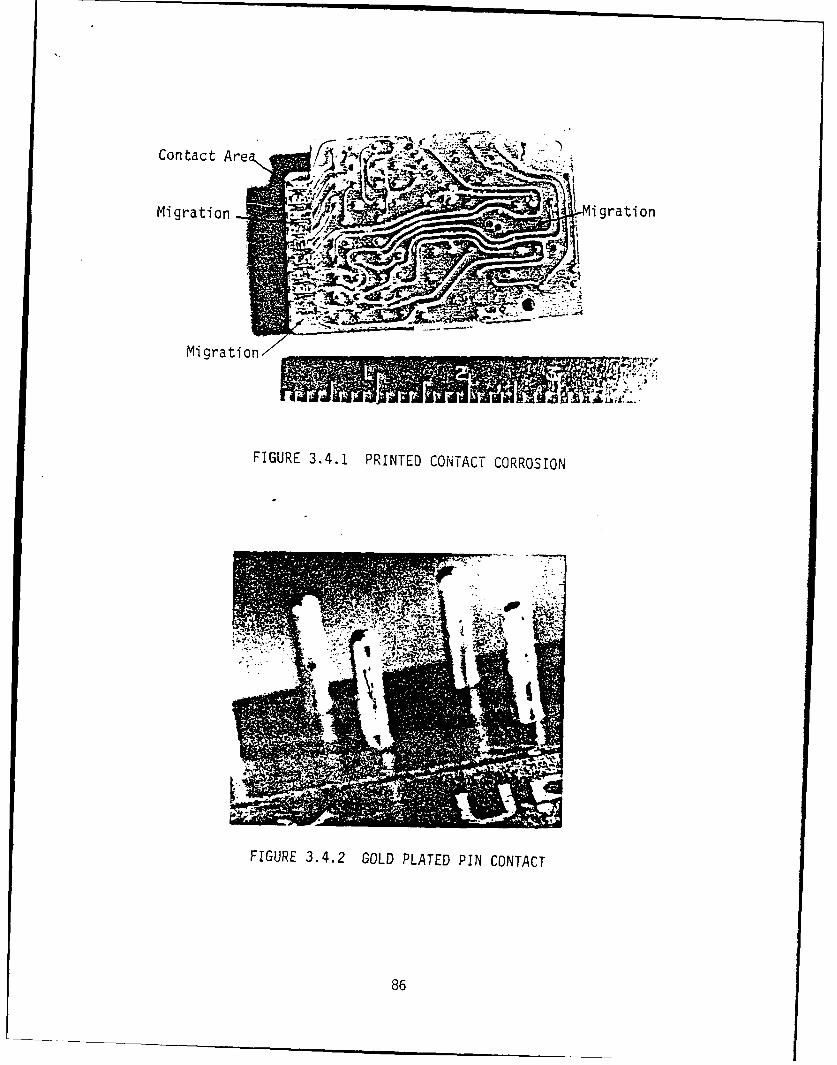
Contact AreM0
Migration igration
Migration
FIGURE 3.4.1 PRINTED CON~TACT CORROSION
FIGURE 3.4.2 GOLD PLATED PIN CONTACT
86
Kovar,Lead
FractureI.IL
UndercutCorrosion
7. Z031.ss-
FIGURE 3.5 CORRODED H.S. PIN
87
gains in weight and volume, ICs were plastic encapsulated for
commercial use. See Figure 3.6.1. These were adapted for military
use initially in the ARC-115 Radio-Transmitter. High failure of the
ICs and subsequent failure analysis revealed that corrosion of the
IC aluminum lands was caused by uncured ingredients in the plastics
being used, and the bonding of gold leads on aluminum lands. See
Figure 3.6.4, 3.6.5. The cure required that only certain plastics,
with no harmful ingredients, capable of being thoroughly cured (no
residual uncured ingredients) and relatively impervious to moisture
could be used. Figure 3.6.2 shows the polarity schematic of a type
IC, and Figure 3.6.3 shows the analysis necessary to explain
demetallization shown in Figures 3.6.4 and 3.6.5.
3.7 Lead Wire, Tabs
Lead wires used with parts which are bent and inserted into PWA
soldered holes under strain are also subject to vibration and shook
stresses and to corrosion by residual fluxes. Tabs used with flat
packs and DIPs and hybrid microcircuits are also sub"nct to the same
conditions. Corrosion can take place at the body-to-lead wire
interface or at the lead wire to PWA interface. Corrosion can take
place, and if strain cracks are present, failure can occur. First
of all, thorough cleaning and conformal coating plus mounting and
cushioning when assembled onto PWAs to prevent vibration damage are
all preventive measures. See Figures 2.3.11.3, 2.3.11.4 and
2.3.11.5. Sharp small angle bends in the copper lead wire should
also be avoided.
88
EPOXY EPOXY SILICONE EPOXY SILICONE
INP N NPN PNP NPN N PN NPN
I ~~~ II I
FIGURE 3.6.1 TYPICAL PLASTIC DEVICES
89
4 .
A,,
o!d ~~-o 4(v ,, 1 4( a ,o,,,c c ll -- 0. Ilko
FIGURE 3.6.2 POLARITY SCHEMATIC OF IC CROSS SECTION
//2 o , A c/4A-~ode CA
3 C/.-~' -4', ,Vft3 - 41C1
4vxcC ec lc A a 1oe /V. 0/
A/ ,l.,Xra-O,
C.14-/' Ad- £*4..4 'i'rov
FIGURE 3.6.3 ZERO BIAS WITH DISTILLED WATER AND SALT
90
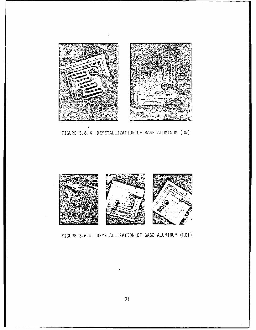
AV
v v;
FIGURE 3.6.4 DEMETALLIZATION OF BASE ALUMINUM (ow1)
91
4. Corrosion Prevention Measures
4.1 General
In the corrosion tutorial presented in preceding paragraphs, many
preventive techniques were mentioned. It would be appropriate to
summarize prevention in an organized fashion with "Do's and
Don'ts". It must be emphasized that there are many design decisions
and trade-off studies which will impact upon corrosion prevention
and control. Specification requirements leave room for trade-off
decisions on a wide range of objectives and engineering practices to
meet not only performance, cost and milestone schedules, but also
reliability and maintainability requirements; of which corrosion
prevention and control are a part. Consequently, in every material
selection and design decision to be made, the question to be
answered is: How will the decision affect corrosion resistance and
field service life? During the acquisition of C/E equipments, many
factors need to be considered and reviewed for corrosion impact.
Each of these will be listed for each acquisition phase.
In addition, to impact upon performance reliability and maintenance,
the cosmetic appearance of corroded equipment will also impact upon
the confidence the soldier operator will have on using and
maintaining his equipment in the field. Noncorroded clean equipment
will receive more confidence and use than dirty corroded equipment
and also last longer.
92
4.2 Corrosion Prevention Measures During Acquisition
The following paragraphs will delineate factors to be considered for
Corrosion Prevention Advisory Board (CPAB) review during contractual
phases of acquisition, Material Use and Selection, Design decisions,
and "Do's and Don'ts".
4.2.1 Concept Exploration Phase
The following tasks should be reviewed by CPAB and monitored by
PM/PCB throughout the acquisition cycle to define Corrosion Control
& Prevention goals specifically tailored to fit the particular
system being acquired:
- Review ROC, Mission Profile and Operated Modes
- Determine Platform Usage, Per Para 4.2 MIL-STD-810D
- Estimate Field Service Life (i.e.: 10 years, 20 years)
- Develop Environmental Design Criteria & Test Plan in the Test &
Evaluation Master Plan (TEMP)
- Review Development & Validation Phase Specification plus TDP to
assure CPC requirements are included in the D&V Phase
4.2.2 Demonstration & Validation Phase
During D&V Phase, many design decisions are achieved as a result of
trade-off studies. Each decision should be evaluated to determine
impact on CPC by participating in the following program phases:
93
Review RAM Plan for Environmental Test Plan
Prepare Draft CPC Plan, Scope of Objectives
Participate in Design Reviews, Trade-off Study Decisions
Provide Inputs to DT/OT-I Plans
Review TEMP to assure adequate Environmental Tests and that
Corrosion Critical Failure Criteria definitions are included.
4.2.3 Full Scale Development (FSD)
In many cases, corrosion occurs because a bad design, an unsuitable
materials have been chosen or a production process has not been
suitably controlled. Adequate specifications (MIL-P-11268 and
MIL-STD-454) are applicable which, if enforced, will result in high
materiel corrosion resistance. The CPAB should review the following
plans to assure CPC objectives and requirements will be adequately
planned and budgeted for and that adequate testing and evaluation
are conducted:
- Review Contractors Reliability Program Plan
- Update TEMP
- Update CPC Plan
- Review Parts Control (Non-Std. Parts Approvals) Plan
- Review Effects of Functional Testing, Storage, Handling,
Packaging, Transportation, Maintenance Requirements
- Review Reliability Test Plan Procedures
94
Failure Modes, Effects & Criticality Analysis (FMECA) FRACAS
Plans
Participate in Failure Review Board
Review Environmental Test Reports (DT-I)
Provide Input to DT-II Scoring Conference
Provide Warranty Input (Insist on plans for corrosion failure
analysis of items returned for repair under warranty.)
In Full Scale Development, all design and material selection and use
decisions must be reviewed to consider their effect on corrosion
resistance and deterioration control as planned and implemented in
the above listed plans and procedures usually accomplished during
FSD. During this acquisition phase, many decisions on design,
material selection and processing control are made by the contractor
to meet performance and form-fit-functions. Corrosion prevention
and control objectives must be maintained within these design, cost,
and performance constraints. Achievement of corrosion control
objectives need not be diminished and must always be realized by
developing corrosion solutions without loss of design objectives.
4.2.4 Production
Quality inspection and control must be adequately applied to assure
conformance to specified quality under MIL-P-11268, MIL-STD-454 and
close attention to any corrosion occurring as a result of the
95
environmental tests applied with insistence that any corrosion
defects be corrected. This can be accomplished by monitoring the
following production activities:
- Review FAT results for corrosion results
- Review ECPs for effect on corrosion resistance
- Attend Materiel Review Board and PCB board for decisions
affecting CPC
- Review Group C Test Reports for corrosion failures
- Review Warranty Plan to assure Corrosion Failure Analysis and
fix resolution
- Review Storage Serviceability Standard Plan for packaging,
storage conditions, periodic inspection test plans, RH indicator
in package.
- Review Packaging and Storage Requirements
4.3 Deployment
All corrosion deficiencies occurring in the field should be
considered and processed under Warranty and, if necessary, PIP.
- Attend, Participate with Warranty Review Group
- Review SSS with Depot on storage, packaging
- Review QDRs, SDRs
- Participate in Fielded System Reviews
96
- Follow-up on Corrosion deficiencies reported
- Monitor Corrosion PIPs
- Monitor Quality Levels of spare parts, modules for maintenance
- Visit Depot Maintenance Shops periodically to obtain corrosion
field data.
Monitor Overhaul Procedures
- Review DMWRs
4.4. Materiel Selection and Use
4.4.1 General
In design decisions involving the selection and use of materials, it
is important to consider not only the electrical characteristics,
but also factors such as basic resistance to corrosion,
compatibility between metals, stability of organic materials and
maintainability. Material applications recommendations include:
4.4.2 Galvanic Couples
Minimize dissimilar metals (galvanic) couples. The joining of
dissimilar metals should be limited to those applications where
similar metals cannot be used due to peculiar design requirements.
If absolutely required, however, select the dissimilar mating metals
to minimize the electrochemical potential of the joint. Design the
97
couple so that the anode area of contact is as large as possible so
that corrosion occurs over a larger area at a slower rate. In all
cases involving dissimilar metals, it is essential that the junction
area be cleaned and sealed to minimize the presence of an
electrolyte at the bimetallic interface. This sealing may be
performed by the conformal coating on a PWB, or by application of
sealant for couples located exterior to a LRU. Other couples within
a LRU can be sealed using a non-acetic acid cure RTV (Room
Temperature Vulcanizing), per MIL-A-46146. Where a dissimilar
metals junction is designed for disassembly, such as a grounding or
bonding connection, an easily replaceable anodic (consumable) part,
such as an aluminum washer, should be included in the assembly.
Graphite is a material that is both a good conductor and a good
lubricant. However, this material acts electrochemically like a
noble metal and is cathodic (corrosive) to all structural metals.
It is especially destructive when in contact with aluminum. Because
of its extreme corrosiveness, graphite lubricants in any form should
not be used on CECOM equipment. When graphite is unavoidably
present, as in graphite composite structural parts, ensure that
insulation is applied to electrically isolate any component from
contact with the graphite composite. Lubricants used shall be IAW
Requirement 43 MIL-STD-454.
98
4.4.3 Surface Treatments
All working of aluminum, e.g., cutting, drilling, grinding, forming,
etc. should be completed before surface treatment is applied. Of
the common surface treatments used on aluminum, anodizing provides
the best protection, followed by Chemical Conversion Coating,
MIL-C-5541, Class IA, and lastly by MIL-C-5541, Class 3. All of the
foregoing coatings have insulative properties, decreasing in degree
from anodize to Class 3. In most applications where electrical
conductivity is required, the MIL-C-5541, Class 3, will provide
adequate continuity and offer some environmental protection. Since
even this coating provides some resistance to ground or attenuates
weak signals, areas of this type should be kept to a minimum. For
generally adequate electrical conductivity, per MIL-B-5087, all
contamination and coatings except MIL-C-5541, Class 3, must be
removed to bare aluminum at the point of contact. Treat cleaned
area with MIL-C-5541, Class 3, if some other type of coating has
been removed. Assemble electrical connection and seal entire
junction area. The slight impedance due to the MIL-C-5541, Class 3,
film is the compromise to achieve some corrosion protection and
enhanced coating or sealant adhesion.
4.4.4 Electrical Connectors
Boots (rubber, plastic, elastomeric) have been used over ends of
wire bundles, harnesses, connector backshells and similar
99
applications to seal out moisture, provide strain relief and
abrasion resistance for connectors used in exposed locations. In
applications where the harness breathes, boots can be used only for
strain relief and abrasion resistance. Such boots must contain
provisions for good drainage to prevent the boot from becoming a
"bathtub" area. Boots intended to seal out moisture must be
installed with the prescribed adhesives at both the cable and
connector ends, and can be used only with harnesses that are already
jacketed up to the junction with the boot. Requirement 11
MIL-STD-454 specifies good practice usage for connectors. Corrosion
failure can occur on the pins causing shorting paths on the
insulators surface. Caps should be used for unmated connectors to
keep out moisture and contaminants.
4.4.5 Metals Selection & Use
In the case of metallic materials, the most corrosion resistant
configuration (passivated) should be used with the minimum possible
residual stressing. An experienced Materials Engineer
(Metallurgist), who is also aware of the characteristics and effects
of the possible field environments, should participate in the
selection of metals that are resistant to the adverse features of
that environment.
100
4.4.5.1 Magnesium
Generally, the use of magnesium for any applications in a marine
environment runs a very high risk of failure. If the use of
magnesium is attempted, first priority in all design decisions must
be toward maximizing protection from corrosive conditions. No metal
more cathodic than aluminum should be mated to ragnesium. If at all
possible, do not use magnesium.
Low Pressure Laminates: For structural applications, low pressure
laminates, polyester impregnated glass laminates is a corrosion
resistant substitute for metals and should be considered for many
26applications, especially for magnesium use.
4.4.5.2 Plating Systems
Utilize metal plating, where applicable, to provide sacrificial
protection, barrier protection, as a third metal (such as tin)
interposed between two otherwise incompatible metals, or as a
substitute surface presenting a reduced galvanic voltage
differential to a contacting metal. Use a nickel strike (thin
plate) under gold. Because it promotes solderability and has
outstanding corrosion resistance, gold is widely used as a thin
plating over silver or copper. However, silver diffuses through
gold, as does copper. Gold over either silver or copper accelerates
101
corrosion of the less noble metal at the pores or pinholes in the18
gold. To avoid diffusion and corrosion, and still retain the
strength of the base metal and the corrosion resistance of the gold,
a plating of nickel should be placed on the copper, (instead of
silver) under the gold. Use a nickel strike of at least 50
microinches under a gold plate of no less than 50 microinches. A
continuous, nonporous gold plate is critical to preventing corrosion
of the base metal. Platings of better quality can be achieved over
smoother basis metallic surfaces that have been polished. An
experienced Materials Engineer (Metallurgist) should participate in
the identification of metal applications to avoid problems such as
red plague (a silver-copper intermetallic compound), purple plague
(a gold-aluminum intermetallic compound), metallic whiskers, silver
migration and other potential metallic problems.
4.4.5.3 Organic Coatings
The preferred organic coating system for external surface protection
of the structural metals used in the fabrication of electronic
equipment is an Epoxy Topcoat, MIL-C-2270, over an Inhibited Epoxy
primer, MIL-P-23377. When aluminum is the base metal, the surface
should be anodized or conversion coated prior to priming. While
Polyurethane Topcoat, MIL-C-83286, also provides a tough, yet
flexible coating, the health hazards irvolved in the application of
this paint makes it generally difficult for use in plant paint
facilities.
102
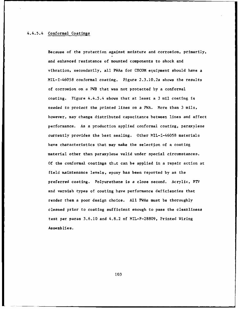
4.4.5.4 Conformal Coatings
Because of the protection against moisture and corrosion, primarily,
and enhanced resistance of mounted components to shock and
vibration, secondarily, all PWAs for CECOM equipment should have a
MIL-I-46058 conformal coating. Figure 2.3.10.2a shows the results
of corrosion on a PWB that was not protected by a conformal
coating. Figure 4.4.5.4 shows that at least a 3 mil coating is
needed to protect the printed lines on a PWA. More than 3 mils,
however, may change distributed capacitance between lines and affect
performance. As a production applied conformal coating, paraxylene
currently provides the best sealing. Other MIL-1-46058 materials
have characteristics that may make the selection of a coating
material other than paraxylene valid under special circumstances.
Of the conformal coatings that can be applied in a repair action at
field maintenance levels, epoxy has been reported by as the
preferred coating. Polyurethane is a close second. Acrylic, RTV
and varnish types of coating have performance deficiencies that
render them a poor design choice. All PWAs must be thoroughly
cleaned prior to coating sufficient enough to pass the cleanliness
test per paras 3.6.10 and 4.8.2 of MIL-P-28809, Printed Wiring
Assemblies.
103
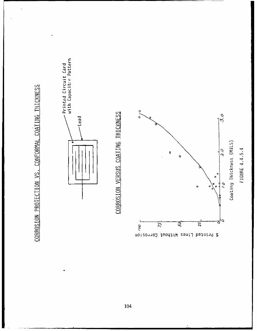
S.-
-C wt 4- i
U- .4-)
C,)=:1 CL
L4-
-J
-I
CDL'
C,(C : ) w )
C)C
0 L
C-) %
LLJ C 04
4.4.6 Solder Flux
Use the lowest acid content flux possible for soldering per
Requirement MIL-STD-454. The term "no acid or acid salts should be
used" is applied to solder, and Military Specifications permit only
noncorrosive and nonconductive fluxes per MIL-F-14256.2 7 However,
even "neutral" fluxes must have some acidity in order to remove
metal oxides and provide a reducing atmosphere to prevent oxide
28formation, and "nonactivated" fluxes can corrode metals. Thus,
any flux residue must be completely removed by cleaning per
MIL-P-28809 and Requirement 9, MIL-STD-454. Welding and brazing
also use fluxes which, if not removed, will provide an electrolyte
to initiate corrosion failures.
4.4.7 Organic Materials
Avoid those materials that outgas corrosive contaminants, support
fungi, absorb moisture, and, in the case of seals, can be degraded
in performance by the presence of fuels and cleaning fluids. All
proposed organic materials should be reviewed by an experienced
materials specialist. Selection of approved organic materials
should be per MIL-P-11268 and Requirement 4 of MIL-STD-454.
105
4.4.8 Gaskets, "0" Rings and Seals
The initial costs of most gaskets, "0" rings or seals are very small
compared to the reliability and maintainability penalties associated
with failure and replacements of these items. Flurocarbon and
fluorosilicone type materials are most resistant to weathering
effects and cleaning fluids.
4.4.9 Conductive Gaskets
A thin conductive gasket of silver, copper or graphite impregnated
material is sometimes used in an attempt to enhance conductivity
between a blade antenna aluminum base and the equipment aluminum
skin. This extreme galvanic couple results in nonconductive
products of aluminum corrosion that greatly degrade system
performance. A clean aluminum antenna base mounted against a clean
case (each treated with Chemical Conversion Coating, MIL-C-5541,
Class 3) and secured with metal screws provides the best long term
mounting. Seal around coaxial exit from the case and around the
periphery of the antenna base, with Sealant, Polysulfide, MIL-S-8802
should be used.
106
4.4.10 EMI Gaskets
Like the conductive gasket, the design of an EMI gasket normally
involves the use of highly cathodic materials (silver, copper,
graphite) mounted against the very anodic aluminum skin. This is
fundamentally a metallurgically unsound condition. The
survivability of such a design depends upon the effectiveness of a
sealing system that precludes "breathing" of ambient air or any
other method of moisture intrusion into the vicinity of the galvanic
couple at the skin/gasket interface. Design ingenuity must also
take into account the problem of restoring this super-sealed
condition following field maintenance or equipment replacement.
4.5 Design Case Configurations to Minimize Corrosion
4.5.1 General
Serious consideration should be given to the design to be used to
protect the interior of equipment housings; especially manpack or
ground portable. The only effective seal that is completely
protective is a hermetic seal design. While this is a very
effective means of minimizing moisture intrusion, the additional
weight, necessary housing rigidity, pres4ure tight sealing, and the
need to maintain and service equipment interiors periodically,
preclude such configurations. The decision on how to protect the
107
interior should be made early in development, since applique methods
such as sealing with caulks or gun sealants are not effective.
Since gaskets allow the housing to be opened in the field, every
item inside should be protected with the assumption that moisture
will eventually get into the equipment.
4.5.2 Case Designs
The available choices are limited to repairable or throwaway items.
For repairable items, gasketed enclosures are necessary. A durable,
rugged design should be used; sufficient to be effective after a
predicted number of maintenance cycles. A renewable device, which
will indicate the RH of the interior mounted and viewable on the
front panel should be used where practicable and cost effective.
Throw away items can be hermetically sealed, canned or potted. The
other option for case design would be an open case design without
water traps and easy drainage at the low point of the case.
Critical portions of the circuit functions should be well-packaged
or hermetically sealed. The following design features can help to
minimize fluid intrusion:
a. Use "0" rings for sealing around all control shafts that must
penetrate into the enclosure.
108
b. Avoid the use of knurled wheels that intrude into the
enclosure. Effective sealing around such wheels is extremely
difficult.
c. Access plates utilizing a gasket for sealing are less subject to
leakage when mounted on a vertical surface.
d. It is preferred to mount electrical connectors horizontally (on
the vertical sides/walls). If it is essential to mount a
connector on the top of a housing, provide a slightly (at least
3/16") raised base for the connector mounting relative to the
surrounding horizontal area. Never put a mating half of a
vertical connector in a well-cup located on top of the case.
The cup will collect standing water.
e. Use an "L" type connector so the wiring enters horizontally into
the upper portion of a vertically mounted connector.
f. For all multicontact connectors, wiring should lead upward
toward the connector to prevent water from running along wire
into the connector. Strain relief is essential to ensure no
side loads exist on wires entering backshell grommets or
potting.
The PWBs, motherboards and feed-through connectors should all be
109
located so they are well above the bottom of a housing (at least
1/2" clearance). In addition, mount PWBs vertically to prevent
condensation and debris from collecting on the board. The edge
connectors should be either on the vertical edges or mounted on the
back of the PWB.
When access to equipment is through the top, use a "shoe box" type
of lid with no penetrations through the top of the lid.
Specifically, avoid countersunk or dimpled fastener holes.
Fasteners through the skirt of the shoe box lid can provide security
without collecting moisture. If fasteners through the top of the
lid are unavoidable, ensure the area over each fastener is covered
with a sealant.
All case designs should allow for easy cleaning or decontaminating
procedures; which are described in maintenance manuals including the
noncorrosive cleaning compound to be used.
4.5.3 Printed Wiring Assemblies, Microcircuits
In most cases, PWAs and microcircuits are the critical functions of
the equipment and must be protected with quality packaging. A
corrosion failure in most situations will usually result in
catastrophic failure. Prevention of corrosion is paramount.
Printed wiring assemblies should conform to MIL-P-28809 and all
110
sections of para 3.10.32 of MIL-P-11268. Microcircuits (integrated
circuits) shall conform to para 3.10.26, Requirements of MIL-STD-454
and MIL-M-38510. For purposes of corrosion prevention, the
following guidelines would be applicable:
4.5.3.1 Materials
Avoid organics, especially those which have residual active
ingredients or impurities. All materials should be completely cured
without residuals, active ingredients and strains. Avoid magnesium
compound metals and higher than necessary high strength aluminums.
4.5.3.2 Designs
Avoid galvanic couples with higher EMF couples than recommended by
Table 2.4.1.1 unless hermetically sealed in accordance with fine and
gross leak test per MIL-STD-883, Test Method 1014. All copper
contact areas should be as smooth as possible with 50 microinches of
nickel undercoat plus 50 microinches of gold plate per MIL-G-45204.
Avoid edge type connectors, and use only pin and socket type
connectors instead.
4.5.3.3 Processes
During processing repairs and assembly, after printing etching,
soldering and assembly, the uncoated PWA should be thoroughly
111
cleaned and tested for cleanliness per para 4.8.2. "Cleanliness and
Resistivity of Solvent Extract," of MIL-P-28809. All PWAs should be
conformally coated per MIL-I-46058. At each intermediate step in
processing and assembly, the PWA shall be protected from industrial
contaminants by specially clean containers with covers and processed
with a minimum of handling. All assembly processes should be
accomplished in a semi-clean room facility.
4.5.3.4 Testing Inspection
After conducting the environmental tests listed in paras 2.6.2
above, the PWA should be thoroughly inspected for gross and minute
corrosion occurrence using microscopic visual inspection. All
instances of the slightest occurrence of corrosion should be
corrected before approvals.
112
5. Field Usage
The main effort in the field to minimize corrosion would be to keep
the equipment clean and as dry as possible. At times, this may be
difficult, but preventive maintenance should include periodic
cleaning and drying. TMs should include cleaning procedures with
safe cleaning solutions and drying procedures at the operational
level. There should be no field repairs of PWAs unless these
repairs can be accomplished with clean room facilities and all
repairs are cleaned and recoated.
113
6. Storage
The Storage Serviceability Standard (SSS) should specify the
necessary storage conditions, i.e., air conditioned, sheltered,
periodic inspection, packaging, etc. An enclosed desiccant
indicator but visible from outside the packaging should indicate the
relative humidity (RH) inside the packaging. With a high RH
indication, the package should be opened and the equipment dried and
a new replacement of the RH indicator inserted. The cause for the
high RH should be determined and corrected. If corrosion has
occurred, the SSS should state overhaul procedures.
114
7. Do's & Don'ts of Design, Materials, Processes
For equipment designers, the following "Do's" and "Don'ts" lists can
serve as general checklists: Do's and Don'ts are general guidelines
which should be used without compromising other important equipment
design factors. A trade-off study should always decide which design
factor is paramount and alternate solutions should be used to avoid
corrosion.
7.1 The "Do's" of Equipment Design
o Design on the assumption that moisture and fluid will be present
in the airframe and equipment.
o Seal all dissimilar metal (galvanic) couples.
o Use a conformal coating on printed wiring boards in accordance
with MIL-1-46058.
o Use an easily replaceable anodic (consumable) part in assembling
grounding or bonding connections.
o Electrically isolate graphite composite materials from electronic
equipment.
115
o Use only electrical connector boots that can be sealed with
adhesives.
o Carefully select a protective system for use on magnesium;
whenever the use of magnesium cannot be avoided.
o Complete the working of aluminum (drilling, cutting, grinding)
prior to surface treatment.
o Use surface treatments (anodize and conversion coatings) on
aluminum.
o Carefully select the metal plating used to provide sacrificial
protection, barrier protection, as a third metal between two
otherwise incompatible metals, or as a substitute surface.
o Use a nickel strike under gold plating.
o Use solder flux with lowest possible acid content.
o Use metallic materials with the most corrosion resistant
configuration (passivated) with minimum possible residual
stressing.
o Use fluorocarbon or fluorosilicone type materials for gaskets,
"0" rings and seals.
116
o Seal conductive and EMI gaskets against moisture/fluid intrusion.
o Use low point drains
o Mount equipment and components at least 1/2 inch above potential
standing water level.
o Use hermetic sealing where possible. Use only potting compounds
without uncured residuals and without corrosive ingredients.
o Use transparent (clear) conformal coating.
o Place ambient pressure sensing components outside equipment
housings.
o Design for maintainability and cleanliness.
o Mount PWBs vertically with the edge connectors on vertical edge
of back of board.
o Mount electrical connectors horizontally.
o Use drip loops on electrical cables.
o Use desiccant systems with outside visual indicators.
117
o Use cooling systems that remove moisture and particulate matter.
o Use "0" rings to seal around control shafts that must penetrate
an enclosure.
o Be aware of various interior and exterior fluids used near
electronics.
o Protect against insulative films on contacts, grounds.
o Recognize the operational environment.
o Recognize the maintenance environment.
o Be aware of maintenance procedures and materials.
o Get the maintenance technician's input during fielded surveys.
o Listen to feedback and lessons-learned.
7.2 The "Don'ts" of Equipment Design
o Don't use dissimilar metal (galvanic) couples if it can be
avoided.
118
o Don't use RTV that contains acetic acid.
o Don't place graphite in contact with aluminum or any structural
metal.
o Don't use heat shrink (non-sealed) electrical connector boots to
stop moisture fluid intrusion.
o Don't mate magnesium to a metal more cathodic than aluminum.
o Don't use gold over silver or copper.
o Don't use organic materials that outgas, support fungi, absorb
moisture or are degraded by maintenance and operational fluids.
o Don't use silver, copper or graphite impregnated material for
conductive or EMI gaskets.
o Don't use top mounted lid fasteners.
o Don't mount PWBs horizontally.
o Don't mount electrical connectors (multicontact or coaxial)
vertically.
119
o Don't place connectors on the bottom edge of a vertically mounted
PWA.
o Don't create side loads or cable tension on the rear seal of
electrical connectors.
o Don't use direct air cooling on active electronic components.
o Don't mount LRUs less than 1/2 inch above the compartment floor.
o Don't use hygroscopic materials.
o Don't use nickel plated electrical connector shells.
o Don't use foam cushioning materials that can deteriorate
(revert).
o Don't permit the presence of water in trap areas.
120
8. Glossary
8.1 Terms, Definitions
ACTIVE METAL - A metal that is in a condition in which it tends to
corrode.
ADDITIVE - A compound added for a particular purpose - in the case
of fuel and lubricants for such purposes as to prevent corrosion gum
formation, varnishes, sludge formations, knocking, etc.
AERATION CELL - An electrolytic cell in which the driving force to
cause corrosion results from a difference in the amount of oxygen in
solution at one point as compared to another. Corrosion is
accelerated where the oxygen concentration is least, for example, in
a stuffing box or under packing, etc.
ALLOY - A combination of two or more metals.
ANAEROBIC - Free of air or uncombined oxygen.
ANION - An ion that carries a negative charge. The chloride ion in
sea water is an anion.
121
41!
ANODE - The electrode of a galvanic cell at which oxidation occurs.
In corrosion, the electrode which is being attacked. The less noble
electrode of an electrolytic cell at which corrosion occurs. This
may be a small area on the surface of a metal or alloy, such as
where a pit develops, or it may be the more active metal in a cell
composed of two dissimilar metals, i.e. the one with the greater
tendency to go into solution. The corrosion process involves the
change of metal atoms into ions with a liberation of electrons that
migrate through the metal to the cathode of the cell.
ANODIC PROTECTION - The reduction or elimination of corrosion of a
metal that can sometimes be achieved by making current flow from it
to the solution as by connecting it to the positive pole of a source
of current. Under most conditions, as the potential of an initially
active metal is gradually shifted in a more noble direction, as by
potentiostatic means, the corrosion current gradually increases.
However, with suitable combinations of metal and solution, a
critical potential is soon reached. At somewhat higher values of
the potential the current drops to a very low value, and the metal
becomes passive. The potential of metal has to be regulated by a
potentiostat.
ANODIZING - A process for thickening the layer of oxide on the
surface of metal, especially aluminum. The article is made by
dipping the anode in a bath of chromic or sulfuric acid. It
provides protection from corrosion and is a good base for paint.
122
AUSTENITIC - A term applied to that condition of iron associated
with a change in crystal structure that makes it nonmagnetic This
occurs with ordinary iron at an elevated temperature. When
sufficient chromium and nickel are present, iron becomes austenitic
(nonmagnetic) at atmospheric temperature. This is the case with the
many stainless steels that contain about 18% chromium and 8% or more
nickel.
BASIS METAL - The underlying metal which is plated or coated.
CATHODE - The more noble electrode of a corrosion cell where the
action of the corrosion current reduces or eliminates corrosion.
CATHODIC PROTECTION - The reduction or elimination of corrosion of a
metal that is achieved by making current flow to it from a solution,
as by connecting it to the negative pole of some source current.
The source of the protective current may be sacrificial metal, such
as magnesium, zinc or aluminum. The current may also be derived
from a rectifier, generator or battery applied through an
appropriate anode which may be consumed by the applied current, as
in the case of steel, or remain substantially unaffected by the
current, as in the case of graphite or platinum. Cathode protection
may become complete when anodic reactions are completely suppressed
and only cathodic reactions occur on the metal surface.
123
CATION - A positively charged ion of an electrolyte. Metallic ions,
such as iron and copper, are cations.
CELL - In corrosion processes, a cell is a source of electrical
current that is responsible for corrosion. It consists of an anode
and a cathode immersed in an electrolyte and electrically bonded
together. The anode and cathode may be separate metals or
dissimilar areas on the same metal.
CHALKING - Deterioration of an organic coating upon exposure that
results in a powdery, chalky residue on the painted surface.
CHEMICAL CONVERSION COATING - A film that is deliberately produced
on a metal by immersing it in, brushing it, or spraying it with a
selected chemical solution for the purpose of providing improved
corrosion resistance to the metal or increasing the adhesion of
organic coatings to be applied later. Coatings covered by
MIL-C-5541 are examples.
CLEAR WATER - Is defined for use in this manual as color free water
containing no visible suspended particles.
124
CONCENTRATION CELL - An electrolytic cell consisting of an
electrolyte and two electrodes of the same metal or alloy that
develops a difference in potential as a result of a difference in
concentration of ions (most often metal ions) or oxygen at different
points in a solution.
CORROSION - The deterioration of a material, usually a metal through
reaction with its environment.
CORROSION FATIGUE - A reduction by corrosion of the ability of a
metal to withstand cyclic or repeated stresses.
CORROSION RATE - The speed at which a metal or alloy is wasted away
because of corrosion. This may be experienced in terms of loss in
weight or loss of thickness in a given period of time.
COUPLE - Two or more dissimilar metals or alloys in electrical
contact with each other so that they can act as the electrodes of a
cell if they are immersed in an electrolyte.S
CRACKING - (a) Localized breaking of a paint film to expose the
underlying material.
(b) Breaking of a metal or alloy in a brittle fashion
along a narrow path or network.
125
CREVICE CORROSIONS - Corrosion that occurs within or adjacent to a
crevice formed by contact with another piece of the same or another
metal or with a nonmetallic material. When this occurs, the
intensity of attack is usually more severe than on surrounding areas
of the same surface.
CRITICAL HUMIDITY - Under controlled conditions, a metal or alloy
will not corrode if relative humidity is kept below a certain
value. In the presence of hygroscopic (moisture absorptive) solids
or corrosion products the critical humidity will be lowered. Steel
will not corrode if the relative humidity is under about 30% in a
marine atmosphere.
DEPOSIT ATTACK - The excessive corrosion that may be deposited on a
metal surface and thus shield it from ready access to oxygen or ions
in solution. This is a form of concentration cell corrosion.
ELASTOMER - Substance having some of the physical properties of
rubber. MIL-S-8802 sealants are examples of an elastomer.
ELECTRODE - A metal or alloy that is in contact with an electrolyte
and serves as the site where electricity passes in either direction
between the electrolyte and metal. The current in the electrode
itself is a flow of electrons, whereas, in the electrolyte, ions
carry electric charges and their orderly movement in solution
constitutes a flow of current in the electrolyte.
126
ELECTROLYTE - Any substance which, in solution or fused, exists as a
electrically charged ion that renders the liquid capable of
conducting a current. Soluble acids, bases and salts, such as sea
water, are electrolytes.
ELECTROMOTIVE FORCE SERIES (ENF) - The elements can be listed
according to their standard electrode potentials. The more negative
the potential the greater the tendency of the metals to corrode but
not necessarily at high rates. This series is useful in studies of
the thermodynaiic properties but does not indicate the rates of
corrosion. A hydrogen gas electrode is the standard reference and
is placed equal to zero. All potentials are positive or negative
with respect to the hydrogen electrode. In this country, the
potentials of zinc and iron are written as negative and those of
copper and platinum positive.
EMBRITTLEMENT - Severe loss of ductility of a metal alloy that
results in a brittle fashion.
EROSION - Destruction of a metal by the combined action of corrosion
and abrasion or attrition by a liquid or gas with or without
suspended matter.
EXFOLIATION - Breaking away from a surface in flakes or layers.
127
FATIGUE - The tendency for a metal to crack and fracture in a
brittle manner under conditions of cyclic stresses at stress level
below its breaking strength.
FAYING SURFACE - The common surface formed by matting parts.
FILIFORM CORROSION - Corrosion that develops under coatings on
metals as fine ragged hairlines, usually wavy or curved and randomly
distributed.
FILM - A thin layer of material that may or may not be visible.
FRETTING CORROSION - Corrosion at the interface of two contacting
surfaces usually under high pressure and subject to very minute
slippage due to relative vibration of surfaces that ordinarily are
not supposed to move relative to each other as a shrink fits.
GALVANIC - In this manual, the flow of direct current between
dissimilar metals.
GALVANIC CORROSION - The increased corrosion above normal corrosion
of a metal that is associated with the flow of current to a less
active metal in the same solution and in contact with the more
active metal.
128
GALVANIC SERIES - A list of metals and alloys arranged in order of
their relative potentials in a given environment. The order of
their arrangement in this list may be different in other
environments.
HYDROGEN EMBRITTLEMENT - Loss of ductility of a metal caused by the
entrance of absorption of hydrogen into the metal as in the pickling
of steel.
IMPINGEMENT ATTACK - Corrosion that is associated with turbulent
flow of a liquid as at the entrance of a condenser tube or around
bends in a pipe line.
INHIBITOR (AS APPLIED TO CORROSION) - A chemical substance or
mixture which when added in small amounts to a solution markedly
decreases corrosion.
INORGANIC COATINGS - Electroplates, conversion coatings, anodic
coatings, phosphates, and oxide coatings.
INTERGRANULAR CORROSION - Corrosion along grain boundaries
ION - An electrically charged atom or group of atoms. The sign of
the charge is positive in the case of cations and negative in the
case of anions.
129
LOCAL CELL - A cell in which the driving force is due to difference
in potential between areas on a metal or alloy surface immersed in
an electrolyte. The potential difference may be due to inclusions,
lack of homogeneity, varying concentration of the solution with
respect to oxygen or metal ions, etc.
MATTE SURFACE - A metal with a low specular, or mirror-like,
reflectivity as in the case of an etched or sandblasted surface.
METAL ION CONCENTRATION CELL - A cell established on a metal surface
due to different concentrations of its ions in the electrolyte where
it is in contact with the metal surface. These variations in
concentration result in local differences in potential thus allowing
the establishment of local cell.
MILL SCALE - The heavy oxide layer formed during hot fabrication or
heat treatment of metals. The term is most frequently applied to
the scale of mixed iron oxides on iron and steel.
MINOR CORROSION - An existing corrosion discrepancy which, by the
dictates of good maintenance practice, should be corrected on an
noninterference basis of other activities.
NOBLE METAL - An metal that is so inert that it is usually found as
uncombined metal in nature. Unattackable or more resistant to
corrosion. Platinum, gold and silver are noble metals.
130
ORGANIC COATINGS - Paint, lacquer, plastics, greases, etc.
OXIDATION - Generally speaking, in chemical terms, any change
involving the loss of electrons by an atom constitutes oxidation,
hence any anode or corrosion process involves oxidation of the metal
in a true chemical sense. More specifically, it also may imply the
destruction of a metal or alloy as a result of the direct action of
oxygen on the metal, e.g., the scaling of steel at a high
temperature.
PASSIVATION - The process or processes by means of which a metal
becomes inert to a given corrosive environment.
PASSIVATOR - An inhibitor that causes a shift in the potential of a
metal in the inhibited solution to a more cathodic or
electropositive value and thereby makes the metal more resistant to
corrosion by the solution. Chromates inhibit corrosion of steel by
water in this manner.
PASSIVE-ACTIVE CELL - A cell involving conditions in which the EMF
is due to the potential difference between a metal in an active
state and the same metal where the one surface is in an active state
and the other surface a passive state. The pitting of stainless
steel in sea water is due to a cell set up between an active surface
within a pit and the passive surface surrounding it.
131
PASSIVE - State of a metal that is active in the EMF Series, or an
alloy composed of such metals, when it exhibits an appreciably
greater resistance to corrosion and behaves more like a less active
or noble metal in resisting corrosion and by exhibiting a relatively
noble potential in a galvanic series.
PATTNA - A green or greenish-blue coating which forms on copper or
copper alloys exposed to the atmosphere.
pH - The acidity of a solution is determined by the concentration of
hydrogen ions in it. The pH of a solution is a term used to express
the effective hydrogen ions in it. In terms of the effective
hydrogen ion concentration. It ranges from pH-I to pH-14. A value
of pH-7 indicates a neutral solution. Values lower than 7 indicate
an acid condition. The stronger the acidity, the lower the pH.
Conversely, values of pH above 7 indicate an alkaline condition, the
higher the pH, the more alkaline the solution. Fresh water usually
exhibits a pH of about 6 to 7. Sea water ranges from pH 7.8 to 8.4
with an average of about 8.2.
PITTING - A form of corrosion that develops in highly localized
areas on a metal surface that is not attacked elsewhere to any great
extent. This results in the development of cavities which are
termed pits. They may vary from deep cavities of small diameter to
relatively shallow depressions.
132
POTENTIAL CORROSION - A condition which if left unchanged can create
a corrosion problem.
PRIMER COAT - The first coat of a protective paint, etc. Originally
applied to improve adherence of the succeeding coat, but now usually
containing an inhibitor pigment such as zinc chromate or red lead.
RELATIVE HUMIDITY - The ratio, expressed as percentage, of the
concentration of water vapor in the air to the water vapor
concentration that it would have if saturated at the same
temperature.
RUSTING - Corrosion of iron or iron-base alloys resulting in the
formation of corrosion products on the surface that consists mainly
of hydrated ferric oxide with a color from red to yellow hues.
SCALING - The formation at high temperatures of partially adherent
layers of corrosion products on a metal surface.
SEVERE CORROSION - An existing corrosion condition that has
progressed to the point where the structure integrity of the unit is
questionable. It should be corrected prior to the units next
operating cycle.
SLUSHING COMPOUND - A nondrying oil, grease, or similar organic
compound which when applied to a metal protects against corrosion.
133
SPALLING - The chipping, fragmenting, or separation of particles
from a surface; such as a paint or coating.
STRESS CORROSION - Corrosion that is accelerated by stress, either
residual internal stress in the metal or externally applied stress.
STRESS CORROSION CRACKING - Cracking that results from the combined
effects of corrosion and stress.
TARNISH - Surface discoloration caused by formation of a thin film
of corrosion product or oxide film.
8.2 Acronyms
CCC Command Control Center
CECOM Communications-Electronics Command
C/F/M Corrosion/Fungus/Moisture
CPC Corrosion Prevention & Control
DMWR Depot Maintenance Work Requirements
DT/OT-1 Development Tests/Operational Tests
D&V Demonstration & Validation
ECP Engineering Change Proposal
ENF Electro-Motive Force
EMI Electro-Motive Interference
ESS Environmental Stress Screening
134
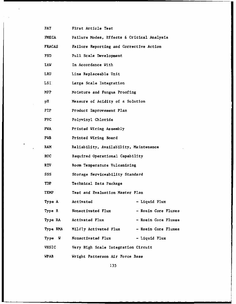
FAT First Article Test
FMECA Failure Modes, Effects & Critical Analysis
FRACAS Failure Reporting and Corrective Action
FSD Full Scale Development
lAW In Accordance With
LRU Line Replaceable Unit
LSI Large Scale Integration
MFP Moisture and Fungus Proofing
pH Measure of Acidity of a Solution
PIP Product Improvement Plan
PVC Polyvinyl Chloride
PWA Printed Wiring Assembly
PWB Printed Wiring Board
RAM Reliability, Availability, Maintenance
ROC Required Operational Capability
RTV Room Temperature Vulcanizing
SSS Storage Serviceability Standard
TDP Technical Data Package
TEMP Test and Evaluation Master Plan
Type A Activated - Liquid Flux
Type R Nonactivated Flux - Rosin Core Fluxes
Type RA Activated Flux - Rosin Core Fluxes
Type RMA Mildly Activated Flux - Rosin Core Fluxes
Type W Nonactivated Flux - Liquid Flux
VHSIC Very High Scale Integration Circuit
WPAB Wright Patterson Air Force Base
135
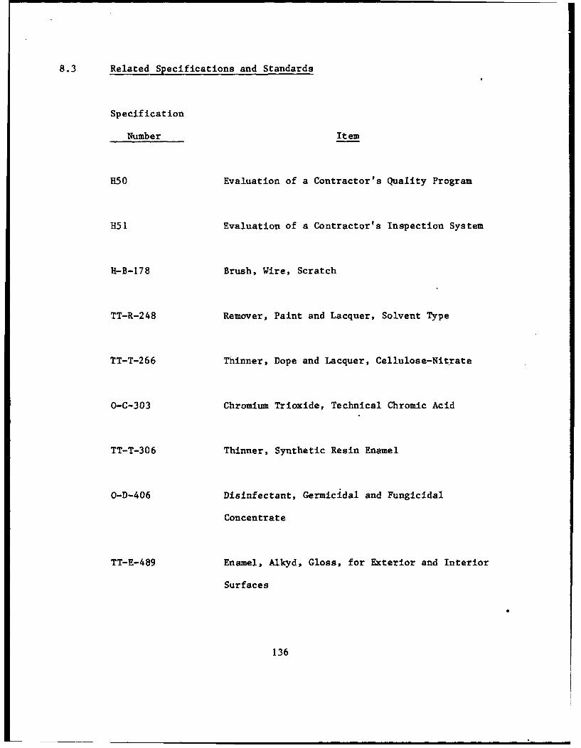
8.3 Related Specifications and Standards
Specification
Number Item
H50 Evaluation of a Contractor's Quality Program
R51 Evaluation of a Contractor's Inspection System
H-B-178 Brush, Wire, Scratch
TT-R-248 Remover, Paint and Lacquer, Solvent Type
TT-T-266 Thinner, Dope and Lacquer, Cellulose-Nitrate
O-C-303 Chromium Trioxide, Technical Chromic Acid
TT-T-306 Thinner, Synthetic Resin Enamel
O-D-406 Disinfectant, Germicidal and Fungicidal
Concentrate
TT-E-489 Enamel, Alkyd, Gloss, for Exterior and Interior
Surfaces
136
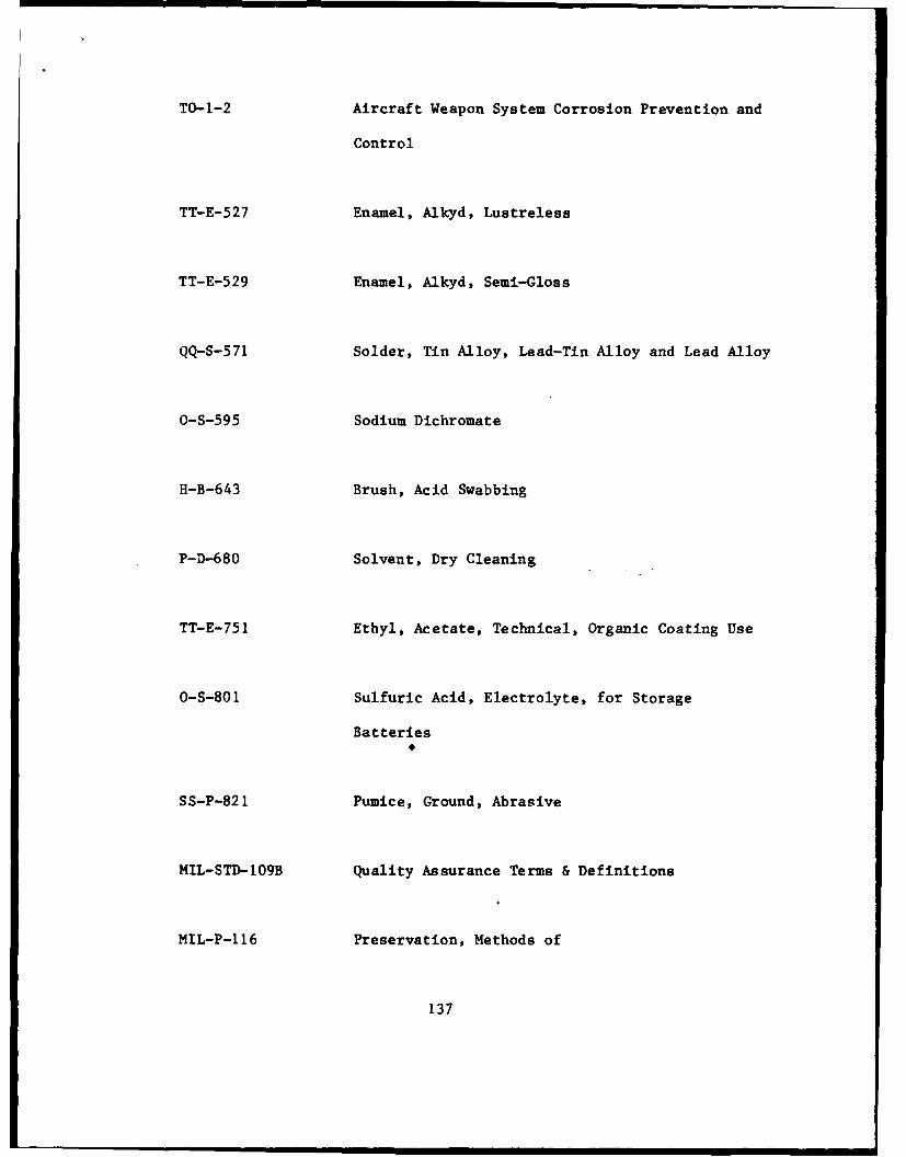
TO-1-2 Aircraft Weapon System Corrosion Prevention and
Control
TT-E-527 Enamel, Alkyd, Lustreless
TT-E-529 Enamel, Alkyd, Semi-Gloss
QQ-S-571 Solder, Tin Alloy, Lead-Tin Alloy and Lead Alloy
0-S-595 Sodium Dichromate
H-B-643 Brush, Acid Swabbing
P-D-680 Solvent, Dry Cleaning
TT-E-751 Ethyl, Acetate, Technical, Organic Coating Use
O-S-801 Sulfuric Acid, Electrolyte, for Storage
Batteries0
SS-P-821 Pumice, Ground, Abrasive
MIL-STD-109B Quality Assurance Terms & Definitions
MIL-P-116 Preservation, Methods of
137
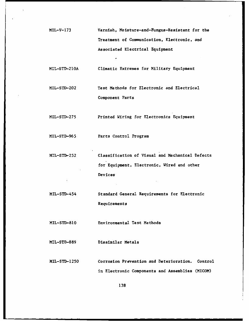
MIL-V-173 Varnish, Moisture-and-Fungus-Resistant for the
Treatment of Communication, Electronic, and
Associated Electrical Equipment
MIL-STD-210A Climatic Extremes for Military Equipment
MIL-STD-202 Test Methods for Electronic and Electrical
Component Parts
MIL-STD-275 Printed Wiring for Electronics Equipment
MIL-STD-965 Parts Control Program
MIL-STD-252 Classification of Visual and Mechanical Defects
for Equipment, Electronic, Wired and other
Devices
MIL-STD-454 Standard General Requirements for Electronic
Requirements
MIL-STD-810 Environmental Test Methods
MIL-STD-889 Dissimilar Metals
MIL-STD-1250 Corrosion Prevention and Deterioration. Control
in Electronic Components and Assemblies (MICOM)
138
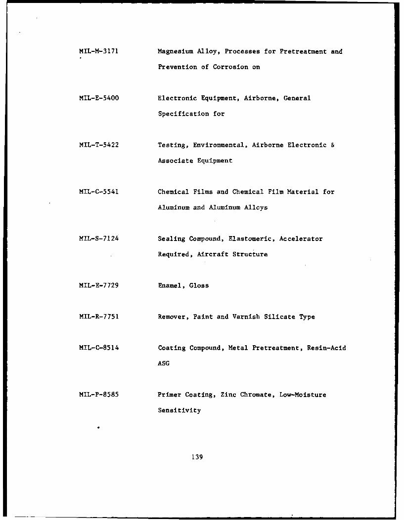
MIL-M-3171 Magnesium Alloy, Processes for Pretreatment and
Prevention of Corrosion on
MIL-E-5400 Electronic Equipment, Airborne, General
Specification for
MIL-T-5422 Testing, Environmental, Airborne Electronic &
Associate Equipment
MIL-C-5541 Chemical Films and Chemical Film Material for
Aluminum and Aluminum Allcys
MIL-S-7124 Sealing Compound, Elastomeric, Accelerator
Required, Aircraft Structure
MIL-E-7729 Enamel, Gloss
MIL-R-7751 Remover, Paint and Varnish Silicate Type
MIL-C-8514 Coating Compound, Metal Pretreatment, Resin-Acid
ASG
MIL-P-8585 Primer Coating, Zinc Chromate, Low-Moisture
Sensitivity
139
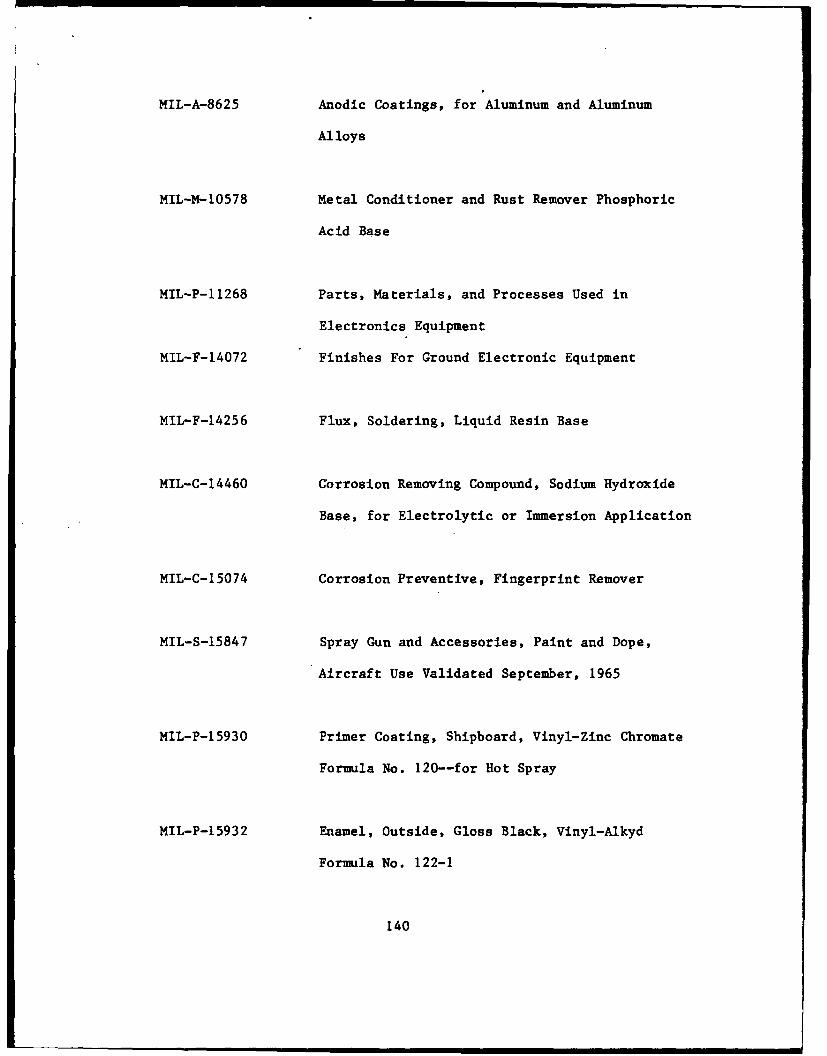
MIL-A-8625 Anodic Coatings, for Aluminum and Aluminum
Alloys
MIL-M-10578 Metal Conditioner and Rust Remover Phosphoric
Acid Base
MIL-P-11268 Parts, Materials, and Processes Used in
Electronics Equipment
MIL-F-14072 Finishes For Ground Electronic Equipment
MIL-F-14256 Flux, Soldering, Liquid Resin Base
MIL-C-14460 Corrosion Removing Compound, Sodium Hydroxide
Base, for Electrolytic or Immersion Application
MIL-C-15074 Corrosion Preventive, Fingerprint Remover
MIL-S-15847 Spray Gun and Accessories, Paint and Dope,
Aircraft Use Validated September, 1965
MIL-P-15930 Primer Coating, Shipboard, Vinyl-Zinc Chromate
Formula No. 120--for Hot Spray
MIL-P-15932 Enamel, Outside, Gloss Black, Vinyl-Alkyd
Formula No. 122-1
140
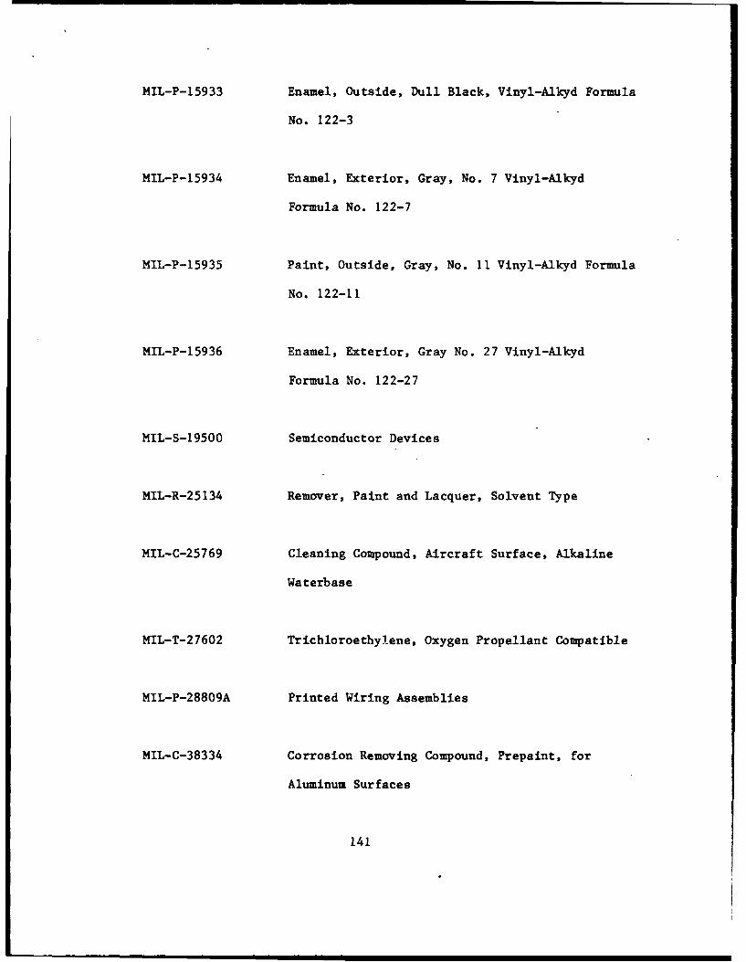
MIL-P-15933 Enamel, Outside, Dull Black, Vinyl-Alkyd Formula
No. 122-3
MIL-P-15934 Enamel, Exterior, Gray, No. 7 Vinyl-Alkyd
Formula No. 122-7
MIL-P-15935 Paint, Outside, Gray, No. 11 Vinyl-Alkyd Formula
No. 122-11
MIL-P-15936 Enamel, Exterior, Gray No. 27 Vinyl-Alkyd
Formula No. 122-27
MIL-S-19500 Semiconductor Devices
MIL-R-25134 Remover, Paint and Lacquer, Solvent Type
MIL-C-25769 Cleaning Compound, Aircraft Surface, Alkaline
Waterbase
MIL-T-27602 Trichloroethylene, Oxygen Propellant Compatible
MIL-P-28809A Printed Wiring Assemblies
MIL-C-38334 Corrosion Removing Compound, Prepaint, for
Aluminum Surfaces
141
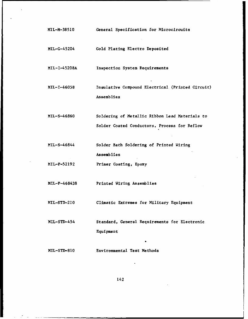
MIL-M-38510 General Specification for Microcircuits
MIL-G-45204 Gold Plating Electro Deposited
MIL-I-45208A Inspection System Requirements
MIL-I-46058 Insulative Compound Electrical (Printed Circuit)
Assemblies
MIL-S-46860 Soldering of Metallic Ribbon Lead Materials to
Solder Coated Conductors, Process for Reflow
MIL-S-46844 Solder Bath Soldering of Printed Wiring
Assemblies
MIL-P-52192 Primer Coating, Epoxy
MIL-P-468438 Printed Wiring Assemblies
MIL-STD-210 Climatic Extremes for Military Equipment
MIL-STD-454 Standard, General Requirements for Electronic
Equipment
MIL-STD-810 Environmental Test Methods
142
8.4 References
1. Keynote Address, Gen. Bryce Poe II, Commander, AF Logistics
Command, Wright Patterson, AFB, Ohio - Proceeding of the 1980
Tri-Service Conference on Corrosion.
2. "Corrosion Control of Army Electronics Equipment" by
Charles P. Lascaro, US Army Electronics Command, Ft. Monmouth,
Presented at 1976 Tri-Service Conference on Corrosion,
MCIC-77-33, Published by Metals & Ceramics Information Center,
Battelle Columbus Laboratories.
3. Navy Maintenance Support Office Instruction 4790.1, Catalog of
Aviation 3M Information Reports, NAMSO, Mechanicsburg, PA
17055.
4. Chief of Naval Operations Instruction 4790.2, Naval Aviation
Maintenance Program, Chief of Naval Operations, Washington,
D.C. 20350.
5. Naval Air Systems Command Instruction 5400.15, Master List of
Engineering Cognizance Assignments, Naval Air Systems Command,
Washington, D.C., 20361.
6. NAVAIR 16-1-540, Avionics Cleaning and Corrosion
Prevention/Control, September 1981.
143
7. Anon., Test Report on Avionics Corrosion Control Program -
Evaluation of Equipment for Cleaning of Avionics, Resource
Management Systems Report, R79-01, May 1979.
8. Schmidt, R.D., RT-591/APN-130 and RT-908/APN-182 Radar
Receiver-Transmitter Corrosion Problems, NARF North Island
Engineering Report No. 10-74 of September 1974.
9. DeLong, G.E.; Myrben, L. C.; Carrato, A. F.; and Shaffer, I.
S.; Aircraft Antenna and Electrical Bonding Corrosion Control,
Report No. NADC-8009-60, Naval Air Development Center,
Warminster, PA., April 1980.
10. Carrato, A. F.; Shaffer, I.S.; and Richwine, R. H.; Corrosion
in Naval Aircraft Electronic Systems, National Association of
Corrosion Engineers Conference, New Orleans, LA, October 1978.
11. Anon, Money, Manpower Called Keys to Progress, Aviation Week &
Space Technology, October 6, 1980.
12. Reboul, M. C., Galvanic Corrosion of Aluminum, National
Association of Corrosion Engineers, Corrosion, V. 35#9,
September 1979.
144
13. "The Role of Quality Control in Preventing Corrosion in
Electrical Circuitry" by C. H. Hutcherson, Materials
Protection, Vol. 7, No. 6, June 1968.
14. Printed Circuits, "Assembly & Joining Techniques", published by
IPC, 1717 Howard St., Evanston, Illinois, 60202.
8.5 Pamphlets, Handbooks
15. NAVMAT P-4855-2 Design Guidelines for Prevention and Control of
Avionics Corrosion, June 1983.
16. Carrato, A.F.; Shaffer, I.S.; and Richwine, R.H.; Corrosion in
Naval Aircraft Electronic Systems, National Association of
Corrosion Engineers Conference, New Orleans, LA, October 1978.
17. Anon, Money, Manpower Called Keys to Progress, Aviation Week &
Space Technology, October 6, 1980.
18. Navy Maintenance Support Office Instruction 4790.1, Catalog of
Aviation 3M Information Reports, NAMSO, Mechanicsburg, PA
17055.
19. Chief of Naval Operations Instruction 4790.2, Naval Aviation
Maintenance Program, Chief of Naval Operations, Washington,
D.C. 20350.
145
20. Naval Air Systems Command Instruction 5400.15, Master List of
Engineering Cognizance Assignments, Naval Air Systems Command,
Washington, D.C., 20361.
21. NAVAIR 16-1-540, Avionics Cleaning and Corrosion
Prevention/Control, September 1981.
22. Anon., Test Report on Avionics Corrosion Control Program -
Evaluation of Equipment for Cleaning of Avionics, Resource
Management Systems Report, R79-01, May 1979.
23. Schmidt, R.D., RT-591/APN-130 and RT-908/APN-182 Radar
Receiver-Transmitter Corrosion Problems, NARF North Island
Engineering Report No. 10-74 of September 1974.
24. DeLong, G.E.; Myrben, L.C.; Carrato, A.F.; and Shaffer, I.S.;
Aircraft Antenna and Electrical Bonding Corrosion Control,
Report No. NADC-8009-60, Naval Air Development Center,
Warminster, PA, April 1980.
25. Reboul, M.C., Galvanic Corrosion of Aluminum, National
Association of Corrosion Engineers, Corrosion, V. 35#9,
September 1979.
146
26. Gilbert, L.O., Prevention of Material Deterioration: Corrosion
Control Course, U.S. Army Rock Island Arsenal, 1966.
27. Anon., Reliable Electrical Connections, NASA SP-5002,
Technology Handbook, December 1963.
28. Sparling, R.H., Corrosion Prevention/Deterioration Control
Electronic Components and Assemblies, Engineering Report
CR6-347-958-001, U.S. Army Missile Command, Redstone Arsenal,
Alabama, undated.
29. "Corrosion of Army Electronic Equipment" by Charles P. Lascaro,
1972 Tri-Service Conference on Corrosion MCIC-71-19, Metals and
Ceramics Center, Battelle, Columbus Ohio Laboratories.
30. Corrosion & Anti-Corrosives M. G. Fontana, R. V. Stachle, NY
Plenum Press, 1974, Hex. Libr. No. 620.11
31. Corrosion Prevention for Practicing Engineers, 1970, Barnes &
Noble, Busich, Joseph F.
32. Corrosion Resistance of Metals & Alloys, F. L. LaQue and H. R.
Copson (Edited), First Edition by R. J. McKay & R. Worthington,
Hex. Libr. No. 620.11.
147
33. NACE, Bibliographic Survey of Corrosion, 1950-51, Publication
55-4.
34. NACE Basic Corrosion Course, Houston Texas, 1970, Hex. Libr.
No. N277NBCC, 620.11
35. Fundamentals of Corrosion, Scully J. C. Oxford, NY, Pergmon
Press, 1966, Hex. Libr. No. 620.112.
36. Plastics for Corrosion Resistant Applications by Raymond B.
Seymour, Robert H. Steiner, Reinhold, 1955, Hex Libr. No. 6685
37. Corrosion, Causes and Prevention, Speller, Frank Newman, 1951,
McGraw Hill, Hex Libr. No. 62.11S.
38. Symposium on the State of the Art of Corrosion Testing,
Toronto, 1970, Handbook on Corrosion Testing and Evaluation,
Edited by W. H. Ailor, NY, J. Wiley, 1971, Hex. Libr. No.
620.1125.
39. Corrosion & Corrosion Control, Uhlig, Herbert Henry, NY, Wiley,
1963, Hex. Libr. No. 620.11V.
40. "Corrosion Handbook", Uhlig, Herbert Henry, Electro Chemical
Society, 1948, NY, Wiley, Hex. Libr. No. 620.11.
148
41. Corrosion Resistance Tables, Metals, Plastics, Non-metallics,
Rubbers, Schweitzer, Phillip A., 1976, Hex. Libr. No. 620-1122
S413.
42. Corrosion Engineering, Fontana, Marselio Guido, McGraw Hill,
1967, Hex. Libr. No. 620.112F.
43. Corrosion Resistant Materials Handbook, Mellan, Ibert, 1976,
Hex. Libr. No. 620-112, M524.
44. IEEE Annual Reliability & Maintainability Symposium
Proceedings, Hex. Libr. No. 620.00.45
45. Symposium of the Physics of Failure in Electronics, Chicago,
1963, RADC Series in Reliability, Hex. Libr. No. 653.55.
46. Reliability Physics Symposium, Annual Proceedings", sponsored
by the IEEE Electron Device Group and the IEEE Reliability
Group, 1970-1984, Hex. Libr. No. 620R.
47. Reliable Electrical Connections, EIA Conferences, NY
Engineering Publication C1958, Hex. Libr. No. 621-37R.
48. Reliable Electrical Connections, Proceedings of Second RETMA
Conferences, University of Pennsylvania, Philadelphia, 1956,
1957, Hex. Libr. No. 621.37.
149
49. IEEE Transactions on Components, Hybrids and Manufacturing
Technology.
50. IEEE Transactions on Electron Devices.
51. IEEE Transactions on Parts Materials & Processes.
52. Corrosion, Volume 1: "Corrosion of Metals & Alloys," Edited by
L. I. Shreir, 1963, John Wiley & Sons.
53. "Handbook of Corrosion, Testing & Evaluation," Edited by W. H.
Ailor, Reynolds Metal Co., Sponsored by the Electrotechnical
Company, John Wiley & Sons.
54. "Deterioration of Materials, Causes & Prevention Techniques,"
by Glenn A. Greathouse and Carl J. Weisel, Reinhold Publishing
Co., 1954.
55. "The Fundamentals of Corrosion," J. C. Sculley, Pergamon Press,
1966.
150
9. Contractual Clauses Applicable to Acquisition Clauses
In order to achieve the stated objectives of a CPC plan, planning
should be organized and implemented during all four stages of system
acquisition. An outline of the recommended SOWs for each
acquisition phase is as follows:
9.1 Concept Exploration
Determine from the ROC, mission profile and operational mode
summary, the equipments planned platform use and field exposure in
certain geographic areas during use, transportation and storage in
accordance with paras 4.2.2, 4.5.9 and 4.6 of MIL-STD-810D, the
contractor shall provide the following:
a. The level and need for environmental protection and the level of
corrosion protection needed in designs shall be predicted based
upon the ROC mission profile and operational mode summary.
b. The contractor's organizational element and individual with
corrosion prevention background and experience, who will be
responsible for management for a MADPAC program.
151
9.2 Demonstration & Validation (D&V)
The Contractor shall prepare a Corrosion Control Plan which will
assure that corrosion and deterioration of protective finishes,
coatings and paints will not occur when the completed design is
exposed to the environmental conditions derived from paras 4.2.2 and
4.6 of MIL-STD-810D, AR-70-38 and MIL-STD-210. The planned design
should meet design criteria and process controls listed in
Appendix B of DARCOM R-702-24 and CECOM Supplement 1. The
Reliability Program Plan per MIL-STD-785 shall list plans for
subjecting the Full Scale Development equipments to corrosion stress
testing which will establish the ability of the equipment to
withstand the following environmental tests included in MIL-STD-810:
Method No. Title
506.2 Rain
507.2 Humidity
508.3 Fungus
509.2 Salt Fog
512.2 Leakage (Immersion)
The CPC Plan shall include the following plan details as described
in Appendix A and CECOM Supplement 1 of DARCOM-R-702-24.
152
9.2.1 Deterioration Prevention Discipline
9.2.2 Deterioration Prevention Program Plan and Progress Reports
9.2.3 Management
9.2.4 Quality Control Measures, Inspections
9.2.5 Design Considerations and Prediction of Effectivity During
Storage, Field Use and Transportation
9.2.6 Degree of Protection Required for Each Functional Area and
Package. Include Use of Transit Cases, Trailers, Vans,
Platforms.
9.2.7 Finishes, Surface Treatments, Conformal, Coatings,
Pottings, Internal, External
9.2.8 Materials Used, Metals, Plastics, Fungus and/or Corrosion
Susceptibility, Galvanic Couples, Organics, Outgassings,
Contaminants, Fasteners, Hardware with Stresses Susceptible
to Corrosion, Minimum Strength Levels, Solders, Fluxes,
High Strength Aluminums, High Zinc Brasses, Welding or
Brazing Fluxes, Surface Quality of Contacts, Thickness of
Gold Platings, Thickness of Nickel Underplate,
Gold-Aluminum Intermetallics, Lubricants, Antiseize
Materials, Complete Process Breakdown of Printed Circuit
Assemblies and their Cleaning and Conformal Coating,
Moisture Susceptibility of Honeycomb and/or Foam in Place
Foams, Resistance to Moisture Ingress of all Cases;
Containers; Especially Gasketted Including EMI RTV
sealants.
153
9.2.9 Environmental Testing Schedule for DT/OT-II and Production
9.2.10 Plans for Preparing an SSS
9.2.11 Failure Analysis Plans which covers corrosion events
The contractors shall prepare a draft proposal for warranties
against corrosion failures in the field including a list and
definition of failure types that can occur and a rating of their
criticality to equipment function and performance.
9.3 Full Scale Development (FSD)
The contractor shall update the CPC Plan to include design changes
to indicate corrosion prevention has been considered and will be
effective. Environmental test plans for corrosion during Production
Phase shall be prepared and include samples of all painted, plated,
coated or treated subassemblies or piece part hardware to be tested
per MIL-STD-810D, Method 509.2 Salt Fog to determine quality of
corrosion protection. All sealed containers should be planned to be
tested for leakage per MIL-STD-810D Method 512.2 Immersion.
The contractor shall propose a final Warranty Program which includes
a statement of liability for the contractor to prevent corrosion and
a liability to crr!ct corrosion deficiencies.
154
9.3.1 Suggested Warranty Clause Definition of Corrosion Failures
Prior to any contractual agreement on Warranty, a list of potential
type of corrosion failures, functional or cosmetic, shall be
proposed by the Government; including a definition of environmental
limits of extremes, and a life cycle environmental profile, the
equipment may be exposed to during usage, storage and
transportation, lAW para 4.2.2.2, MIL-STD-810D.
The above list of definitions shall form the basis for remedies
under the conditions of warranty. During the warranty period,
equipments that have failed in the field shall be returned to the
contractor and conduct failure analysis, sufficient to establish the
root cause of failure and such results shall be reviewed by the
CECOM CPC Management Office (PA&T).
155
10. Conclusions
10.1 The Mission Profile, Mode of Operation and projected field climatic
extreme exposures should be used to specify the severity of the
environmental testing to be required in FAT and Group C tests.
10.2 The control and prevention of corrosion in CECOM equipments is
achievable by requiring and enforcing compliance with currently
available specifications and standards. Due to the effect of
rapidly changing techniques, however, it is essential that the
applicable specifications and standards be continually updated
accordingly.
10.3 In every acquisition plan, the CPC plan should be generated in the
Advanced Development phase and updated in ongoing acquisition phases
with periodic progress reports.
10.4 During the development phases, all material selection and design
decisions should be reviewed for impact on corrosion resistance.
During production, all ECPs should also be reviewed for corrosion
impact. During storage, SSSs should require protective storage and
periodic inspections for corrosion. During fielding, field manuals
should describe corrosion inspections and QDRs should be studied for
TNPs. It should be the responsibility of the CPC DPAO to monitor
the above actions.
156
10.5 The seven essential guidelines for CPC are as follows:
- Good design, material selection and quality finishes.
- Cleaning during all phases; especially production fielding and
overhaul.
- Drying interiors (open cover, dry, close cover)
- Protective dry storage.
- Any sign of corrosion after test should be cause for failure.
All environmental tests should be rigorously required and
performed.
- All electrical and mechanical failures should be subject to
failure analysis to determine root cause of failure.
- Warranties should insure against corrosion failures.
10.6 CPC key words are:
CPC Plan
Material Selection
Design Decisions
Process Controls:
MIL-P-11268
MIL-STD-454
MIL-F-14076
MIL-P-28809
Cleanliness
157
Dry Containers, Cases
Environmental Testing
Failure Analysis
SSS
QDR/Technical Need Proposals
Warranty
158