Embed Size (px)
Citation preview

DTICAD-A242 107 ,"' eT
TECHNICAL REPORT ARCCB-TR-91021
EFFECT OF ELEVATED TEMPERATURETENSILE TESTING OF AF1410 STEEL
E. TROIANOD. PEEK
E. NIPPES
JUNE 1991
US ARMY ARMAMENT RESEARCH,DEVELOPMENT AND ENGINEERING CENTER
CLOSE COMBAT ARMAMENTS CENTERBENET LABORATORIES
WATERVLIET, N.Y. 12189-4050
APPROVED FOR PUBLIC RELEASE; DISTRIBUTION UNLIMITED
91-147649 1, 0 'l -5] ] lllll !1!1I1'I111 i11

DISCLAIMER
The findings in this report are not to be construed as an officia
Decarznent o: the Ary position uless so designated by other authori:ed
ioc en-.
-.he -se of trade name 's" and/or -anuiac:urer(s. does not consti:ute
_-. ial ndorsenen: or approva
DESTRUCTON NOT:
.or c-assi-ied doc-.-nents, follow the procedures in DoD 30ZC.-..-M,
nustrla Security Manual, Section if-19 or DoD 3200.1-R, Info--ation
Securi:: ?rogram Regulation, Chapter .X.
:-or unclassified, limited documents, destroy by any method that w:l
.revent disclosure of contents or reconstruction of the document.
-or unclassified, unlimited documents, destroy when the report is
no :cnger needed. Do not return it to the originator.

SECURITY CLASSIFICATION OF THIS PAGE ("oin Data Entered)
READ INSTRUCTIONSREPORT DOCUMENTATION PAGE BEFORE COMPLETING FORM
1. REPORT NUMBER 12. GOVT ACCESSION No. 3. RECIPIENT'S CATALOG NUMBER
ARCCB-TR-91021
A. TITLE (and Subtitle) 5. TYPE OF REPORT & PERIOD COVERED
EFFECT OF ELEVATED TE.%ERATURE TENSILE FinalTESTINC OF AF141C STEEL
6. PERFORMING ORG. REPORT NUMBER
7. AUTHOR(@) 8. CONTRACT OR GRANT NUMBER(&)
E. Troiano, D. Peek, and E. Nippes
(See Reverse)
9. PERFORMING ORGANIZATION NAME AND ADDRESS 10. PROGRAM E...EMENT. PRO.jEC -ASKc
ArmYARDC I AREA A, WORK UNI- NUMBERS
benet Laboratories, SMCAR-CCB-TL IACSN.62.3lL.A.~t~vkleNY 12189-4030 PRON' No. A7Z5NHNM.SC
!I. =DNTROLL.ING OwwICE NAME AND ADDRESS 12. REPORT DATE
7-.S.Army ARDEC June 1991
Close Combat Armaments Center 13. NUMBER OF PAGES
l icatinnv Arsenal, NJ 07806-5000 7014 -uONIT CRING AGENCY NAME & AODRESSU!f different from Controlling Office) j15. SECURITY CL..ASS. (of this6 repot.
IUNCLASSIFIED15is. DECLASSIFICATION DOWNGRADING
SCHEDULE
16- DISTRIBUTION STATEMENT (of this Report)
Approved --or public release; distribution unlimited.
17. DISTRIBUTION STATEMENT (of the abstract entred In Block 20, If different from Report)
IS. SUPPLEMENTARY NOTES
19. KEY WORDS (Continue on rever.e side If necessary and identify by block number)
Tensile TestingMechanical PropertiesSteelThermal TransientsStress Relaxation
21L ANTRACT' ICat~mar ,wwin reeEW if uiwsm, da Idetity by block miinibe)
The effect of thermal and mechanical transients on the material properties ofAF1410 steel for applications in large caliber ballistic weapons was investi-gated. The Gleeble Model 1500 thermomechanical simulation device was used forthe evaluation of elevated-temperature mechanical properties and simulatedfiring cycles. The tensile properties and the age-hardening response weremeasured, as a function of temperature, for one heat of AF1410 steel.
(CONT'D ON REVERSE)
DO~A 7243 frlO PI O 5I SLT UNCLASSIFIED
SECURITY CLAWSFICATIONt OF T~iS PAGE (When Date Entered)

SECURITY C.LASSIFICATION OF THIS PAGE(Whan Data Entetrd)
7. AUTHORS (CONT'D)
D. Peek and E. NippesMaterials Engineering DepartmentRensselaer Polytechnic InstituteTroy, NY 12180-3590
20. ABSTRACT (CONT'D)
The results of the investigation showed that the ultimate tensilestrength, yield strength, and true fracture stress decreased linearlywith increasing temperature, up to 800 0 F. Young's modulus decreasedwith increasing temperature, while Poisson's ratio remained unchanged.The material exhibited stress relaxation at elevated temperatures, butnot at room temperature, when loaded to 80% of its yield strength. itwas found that the yield strength increased when the material had beenpreviousiy aged at the same temperature.
The age-hardening response of the material exhibited a secondaryhardening peak at approximately 9000 F. The room-temperature hardnessincreased with increasing aging temperature up to the secondary hardeningpeak. A rapid decrease in the room-temperature hardness with increasingacing time occurred at 10000F.
UNCLASS IFIED
SECURITY CLASSIFICATION OF THIS PAGE(WIhen Data Entered)

CONTENTS
Page
LIST OF TABLES ....................................... ii
LIST OF FIGURES ...................................... j j
ABSTRACT ............................................... V
i. INTRODUCTION. .....................................
2. MATERIALS AND PROCEDURE ..........................
A. Characterization Of Base Material .........
B. Tensile Testing ........................... -
C. Age-Hardening Response Testing ............
D. Metallography ..............................
3. RESULTS AND DISCUSSION ........................... ZC
A. Evaluation Of Tensile Tests ................ 2 '
B. Evaluation Of Age-Hardening Response Tests 38
4. CONCLUSIONS ...................................... 50
5. LITERATURE CITED ................................. 53
7. APPENDIX ......................................... 55
ea t
D1,!t

LIST OF TABLES
Page
Table 2.1 Chemical Analysis Of AF1410 Steel Used inThis Investigation (in weight percent) ...
Table 2.2 Fundamental Room-Temperature MechanicalProperties Of AF1410 Steel Used In ThisInvestigation ............................
Table 3.1 Tensile Properties For The LongitudinalOrientation Of AF1410 Steel .............. 21
Table 3.2 Tensile Properties For The TransverseOrientation Of AF1410 Steel .............. 22
Table 3.3 Young's Modulus For The LongitudinalOrientation Of AF1410 Steel ............... -
Table 3.4 Young's Modulus For The TransverseOrientation Of AF1410 Steel .... .......... 30
Table 3.5 Stress Relaxation After One Hour For TheLongitudinal Orientation Of AF1410 Steel 35
Table 3.6 Stress Relaxation After One Hour For TheTransverse Orientation Of AF1410 Steel ... 26
Table 3.7 Tensile Properties For The LongitudinalOrientation Of AF1410 That Were PreviouslyStress Relaxed At The Same TestTemperature .. .............................. 9
Table 3.8 Tensile Properties For The TransverseOrientation Of AF1410 That Were PreviouslyStress Relaxed At The Same TestTemperature .. .............................. 40
Table 3.9 The Effects Of Aging Temperature And AgingTime On The Macrohardness Of AF1410 Steel 44
Table 3.10 The Effects Of Aging Temperature And AgingTime On The Microhardness Of AF1410 Steel 45
ii

LIST OF FIGURES
Page
Figure 2.1 Microstructure For The LongitudinalOrientation Of AF1410 Steel, 500X .......
Figure 2.2 Microstructure For The TransverseOrientation Of AF1410 Steel, 500X .......
Figure 2.3 Specimen Design For True Stress - TrueStrain Tensile Tests ....................
Figure 2.4 Specimen Design For Elastic-ModulusTests .. ................................... 13
Figure 2.5 Specimen Design For Stress-RelaxationTests .. ...................................
Figure 2.6 The Relationship Between The TemperatureAcross A Specimen's Free Span And Thetype Of Tensile Test Jaw ................. -5
Figure 3.1 The Ultimate Tensile Strength Of AF1410Steel As A Function Of Temperature ...... 23
Figure 3.2 The 0.1% Offset Yield Strength Of AF1410Steel As A Function Of Temperature ...... 24
Figure 3.3 The True Fracturc Stress Of AF1410 SteelAs A Function Of Temperature ............ 25
Figure 3.4 The Reduction In Area Of AF1410 Steel AsA Function Of Temperature ............... 27
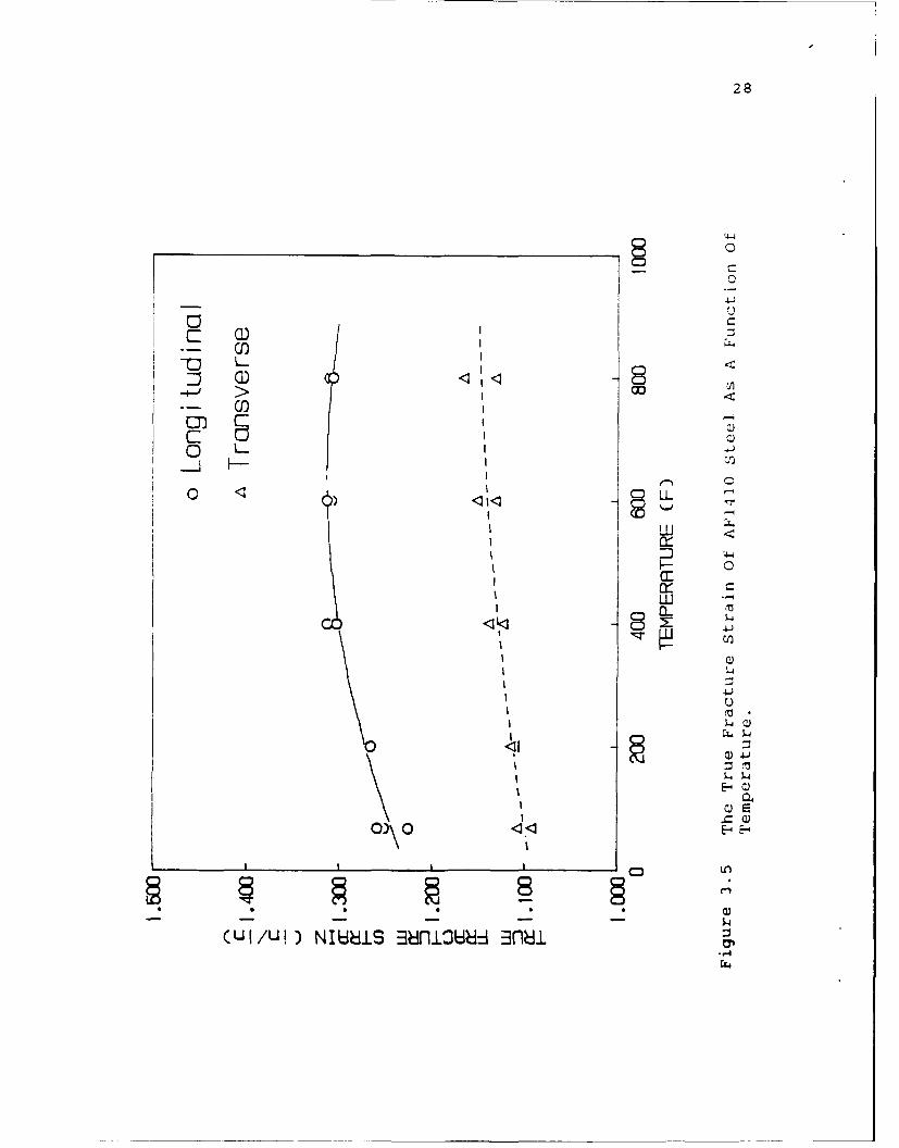
Figure 3.5 The True Fracture Strain Of AF1410 SteelAs A Function Of Temperature ............ 23
Figure 3.6 Young's Modulus Of AF1410 Steel As AFunction uf Temperature .................. 31
Figure 3.7 AF1410 Steel Stress-Relaxation TestResults For The Longitudinal Orientation 33
Figure 3.8 AF1410 Steel Stress-Relaxation TestResults For The Transverse Orientation .. 34
Figure 3.9 The Percent Stress Relaxation After OneHour As A Function Of Temperature ....... 37
iii

Page
Figure 3.10 The 0.1% Offset Yield Strength For TheLongitudinal Orientation Of As-ReceivedAnd Aged AF1410 Steel As A Function OfTemperature .. ............................. i
Figure 3.11 The 0.1% Offset Yield Strength For TheTransverse Orientation Of As-Received AndAged AF1410 Steel As A Function OfTemperature ............................. 42
Figure 3.12 The Age-Hardening Response Of AF1410Steel As A Function Of Temperature ...... 46
Figure 3.13 The Age-Hardening Response Of AF1410Steel As A Function Of Time ............. 47
Figure 6.1 The GPL Program For Room-TemperatureTrue Stress - True Strain Tensile Tests .
Figure 6.2 The GPL Program For True Stress - TrueStrain Tensile Tests Performed At 2000 F
Figure 6.3 The GPL Program For True Stress - TrueStrain Tensile Tests Performed At 4000F 58
Figure 6.4 The GPL Program For True Stress - TrueStrain Tensile Tests Performed At 600°F 59
Figure 6.5 The GPL Program For True Stress - TrueStrain Tensile Tests Performed At 800°F 60
Figure 6.6 The GPL Program For Room-TemperatureElastic-Modulus Tensile Tests ........... 61
Figure 6.7 The GPL Program For Elastic-ModulusTensile Tests Performed At 200°F ........ 62
Figure 6.8 The GPL Program For Elastic-ModulusTensile Tests Performed At 400°F ........ 63
Figure 6.9 The GPL Program For Elastic-ModulusTensile Tests Performed At 600°F ........ 64
Figure 6.10 The GPL Program For Elastic-ModulusTensile Tests Performed At 800°F ........ 65
iv

ABSTRACT
The effect of thermal and mechanical transients on
the material properties of AF1410 steel for applications in
large caliber ballistic weapons was investigated. The
Gleeble Model 1500 thermomechanical simulation device was
used for the evaluation of elevated-temperature mechanical
properties and simulated firing cycles. The tensile
properties and the age-hardening response were measured,
as a function of temperature, for one heat of AF1410
steel.
The results of the investigation showed that
the ultimate tensile strength, yield strength, and true
fracture stress decreased linearly with increasing
temperature, up to 800°F. Young's modulus decreased
with increasing temperature, while Poisson's ratio
remained unchanged. The material exhibited stress
relaxation at elevated temperatures, but not at room
temperature, when loaded to 80% of its yield strength. It
was found that the yield strength increased when the
material had been previously aged at the same temperature.
The age-hardening response of the material
exhibited a secondary hardening peak at approximately 900°F.
The room-temperature hardness increased with increasing
aging temperature up to the secondary hardening peak. A
rapid decrease in the room-temperature hardness with
increasing aging time occurred at 10000F.
v

PART 1
INTRODUCTION
The selection of materials for modern military
structural components is based on traditional design and
economic considerations, as well as new demands for
superior material properties. Not only must a materia
lend itself to fabrication at an acceptable cost and
provide the required strength, but it must also insure a
predictable service life even in the presence of a flaw or
defect.
AFl410 (14wt% Co, 10wt% Ni) steel was developed,
under Air Force sponsorship, for structural applications
where a component will be loaded to near its yield
strength to meet requirements of structural efficiency and
economy. AF1410 steel combines high strength with
superior fracture toughness and stress-corrosion
resistance. The alloying addition of ten percent nickel
and the subsequent heat treatment are primarily
responsible for the relatively high strength and excellent
fracture toughness. The alloy is strengthened during
tempering by carbide precipitation, not by the formation
of intermetallic compounds. Cobalt, added to maintain a
high austenite-to-martensite transformation temperature,
limits the amount of retained austenite in the steel after
1

2
quenching. The low carbon content (0.15wt%) of this alloy
enables the material to be fabricated easily. Furthermore,
the alloy has good hot and cold-working characteristics and
is readily machined.
The high yield strength of AF1410 allows for the
modification of c structural design to achieve increased
weight efficiency. It is therefore of interest to
investigate the effect of thermal cycling on the
material properties of AF1410.

PART 2
MATERIALS AND PROCEDURE
A. Characterization Of Base Material
The chemical comDosition of the AF1410 steel used
in this investigation, based on data obtained from
Universal-Cyclops Specialty Steel Division, is shown in
Table 2.1. The chemical composition of this heat of
AFI410 steel appears to be well within the nominal values
listed in Table 2.1.
The material was forged to dimensional tolerances
set by Watervliet Arsenal/Benet Laboratories. A double
austenitization and age heat treatment was used to develop
maximum toughness and high strength in the AF1410 steel.
A subzero treatment was used to assure minimum retained
austenite (less than 1%). The specific heat treatment is
given below:
1650°F (898 0 C): 1 hour at temperature - oil quench
1525°F (829 0 C): 1 hour at temperature - oil quench
-100°F (-730 C): 1 hour at temperature - air warm
950°F (510 0 C): 5 hours at temperature - oil quench
The fundamental room-temperature mechanical
3

4
TABLE 2.1
Chemical Analysis Of AF1410 Steel
Used In This Investigation (in weight percent).
Element Heat Analysis Nominala
Carbon................ 0.16 0.13-0.17
Manganese............. 0.02 0.10
Silicon............... 0.03 0.10
Sulfur................ 0.001 0.005
Phosphorus............ 0.004 0.008
Chromium.............. 1.94 2.0
Nickel............... 10.20 9.5-10.5
Cobalt......... ...... 13.70 13.5-14.5
Molybdenum............ 1.02 0.9-1.1
Titanium.............. 0.013 0.015
Aluminum.............. 0.002 0.015
Oxvgen................ 0.0019---
Nitrogen.............. 0.0004---
Iron.................. Balance
a. Single values are maximums.

properties for this alloy from the same heat, also
supplied by Universal-Cyclops, are listed in Table 2.2.
Specimens used in this investigation were cut to a
specific specimen geometry (a detailed discussion of the
specimen design will be provided later in this section).
Ec-vated-temperature tensile properties were measured for
two material orientations: longitudinal direction
(parallel to the forging direction) and transverse
direction (perpendicular to the forging direction).
Se," ral small samples of AF1410 steel were sectioned for
metailographic evaluation. Samples of both longitudinal
and transverse orientations were prepared in order to
examine for directionality of the microstructure.
i..nspection of samples in the as-polished condition
revealed a very low inclusion content with no preferred
orientation. Photomicrographs of longitudinal and
transverse samples etched to reveal microstructural
details are shown in Figures 2.1 and 2.2, respectively.
The microstructure is that of tempered martensite with
small amounts of retained austenite. The macrohardness
(HRC or Rockwell "C" hardness) and microhardness (HV or
Vickers hardness) of both orientations were measured.
The measured hardness values were HRC 48 and HV10 00 481,
and were found to be approximately equal for both
longitudinal and transverse orientations.

6
TABLE 2.2
Fundamental Room-Temperature Mechanical PropertiesOf AF1410 Steel Used In This Investigation.
TENSILE PROPERTIESa FRACTURE TOUGHNESSb
UTS 0.2% YS Elong. %RA Kic KIc Q
(KSI) (KSI) (%) (%) (KSIVIE) (KSIV i)
244 223 15.4 69.5 159 200
a. Average of eight tests.
b. KiC is the result of one test, KQ is theaverage of three tests.

Figure 2.1 Microstructure For The LongitudinalOrientation Of AF1410 Steel, 500X.

_t ;4i
..... .. . .
Figure 2.2 Microstructure For The TransverseOrientation of AF1410 Steel, SOOX.

9
B. Tensile Testing
Tensile-test results in this investigation were
generated using the Gleeble 1500, a thermomechanical
simulation device. For elevated-temperature tests, the
Gleeble 1500 utilizes controlled resistance heating. The
specimen is clamped between two copper jaws and a
two-wire, chromel-alumel thermocouple, condenser-discharge
welded to the specimen at its midspan, provides for
temperature measurement and control. In resistance
heating, the maximum specimen temperature occurs at the
midpoint between the two copper jaws (the specimen
midspan). Because the jaws remain at ambient temperature,
there is a temperature gradient along the specimen axis.
The magnitude of this axial temperature gradient is a
function of the jaw separation, thermal conductivities of
the jaw and the specimen materials, and the maximum
(control) temperature. The "hot" gage length is the
effective gage length in a Gleeble test, and this value
must be known for calculation of the strain rate.
True Stress - True Strain Tests
Given the secondary hardening response of AF1410
steel (References 1,2, and 3), the potential exists for

10
material at an elevated temperature (at the specimen
midspan) to be stronger than material at a lower
temperature down the axial temperature gradient.
Therefore, a tensile failure in a resistance-heated
specimen of uniform cross-section could occur at a
location remote from the thermocouple, i.e., at an unkncwn
temperature. For this reason, a continuous-radius gage
length specimen was designed for this investigation. This
specimen design, shown in Figure 2.3, should permit
tensile testing at any temperature, including room
temperature. Additionally, this specimen geometry will
promote fracture at the specimen midspan so that a
diametral dilatometer can be used for strain measurement.
The ultimate tensile strength (UTS), 0.1% offset
yield strength (YS), percent reduction in area (%RA), true
fracture stress, and true fracture strain, of AF1410 steel
were determined using the true stress - true strain
tensile test. A cross-head stroke rate of 0.675 cm/min
was used and the specimen was pulled until failure. The
GPL (Gleeble Programing Language) programswhich generated
the tensile test for the following temperatures: R.T.,
200 0 F, 4000 F, 600 0 F, and 800°F are shown in
Figures 6.1-6.5 of the Appendix. Specimens were brought
up to temperature in ten seconds and held there for thirty
seconds prior to stroke movement. The tensile load, true

'I-
- 2 C)- 2 -4
- '0 -- 4
22 -
o -4
- 2 C)2 -A -
U)
2 U)~ ~- *~- 2 C)
C)
V0
22
0U)C)
C)E.
2 -- I U)- '0
- - C)U)- Q~C)
030'- ~z..

12
stress, and true strain were recorded on an X-Y chart
recorder. The UTS, YS, and true fracture stress were
determined from these data. The %RA and true fracture
strain were determined by optical measurements of the
fracture surfaces of the tensile specimens.
Elastic-Modulus And Stress-Relaxation Tests
The determination of the elastic modulus and
stress relaxation of a material requires a specimen with a
uniform cross-section gage length (these tests are
performed in the elastic region which eliminates the need
for the continuous-radius gage length). The specimen
configurations for elastic-modulus and stress-relaxation
determination are shown in Figures 2.4 and 2.5,
respectively. Both tests require small thermal gradients
and longer work zones ("hot" gage lengths) to obtain mcre
accurate results for the given test temperature. As has
been discussed earlier, the thermal gradient can be
reduced by increasing the length of the free span or by
increasing the end temperature of the specimen. Hence hot
jaws were used, where the temperature of the specimen end
was increased by using a jaw with a lower thermal
conductivity (stainless steel). The relationship between
the temperature across the free span and the type of jaw
used is shown in Figure 2.6 (Reference 4).

13
E- E- 0
EE
EAE E
E
E
E -4

14
EE
''n
SxE
00
ell0
E

15
-1 TEST ZONE STAINLESS AWS
lIEST 'Okf COPPER JAWS-4-
,OW7,
- 7 /LESSC.ONTACrAREA
S /"
RED400[ CZNrACT-- AREA/ / \ \ \ STAWL SSSTEEL.AWS
* / \
'Im P I R A-TU R A,! \
/\¢O"ER JAWS
/\/\
mOMTEMDEATURE
JAW FACE FREE SPAN IAW ACI
LENGTHWISE THERMAL PROFiLE
Figure 2.6 The Relationship Between The TemperatureAcross A Specimen's Free Span And The Type OfTensile Test Jaw.

16
The elastic modulus (E) of the steel was measured
using the following procedure. The specimens were heated
to temperature in 30 seconds, and then held at temperature
for 30 seconds. The specimens were then loaded to 80% of
the yield strength, for the given temperature (R.T.,
2000 F, 400 0 F, 600 0 F, and 8000 F), in 60 seconds.
The load, true stress, change in specimen axial length,
and change in specimen diameter were recorded on an X-Y
chart recorder. These data were then used to calculate
Young's modulus and Poisson's ratio. The GPL programs for
these tests are shown in Figures 6.6-6.10 in the Appendix.
Determination of stress relaxation of the steel
was measured using the following procedure. The Gleeble
1500 system was put in the operational mode three hours
prior to testing to eliminate potential mechanical,
thermal, and electrical drifts and transients that might
occur during long testing times. Specimens were manually
heated and loaded in order to avoid compressive stresses
on the specimen because of thermal expansion of the
material during heating. The hydraulic drift of the
mechanical system was determined and entered in the test
as a ± percent error. The specimens were heated to
temperature in approximately 10 seconds, and the specimen
was allowed to equilibrate at temperature. Specimens were
loaded to 80% of the yield strength, for the given

!?
temperatures (R.T., 2000 F, 4000 F, 6000 F, and
300 0 F), in five seconds or less. The temperature and
stroke position of the jaws were held constant for one
hour. The load and stress of the specimens were recorded
on a strip chart recorder and the percent stress
relaxation after one hour was determined from these data.
Agina Tests
The specimens used in the stress-relaxation tests
(held at temperature for one hour with an applied load)
were unloaded and allowed to cool to room temperature in
air. True stress - true strain tests were then performed
on these stress-relaxation aged specimens. Specimens -..ere
tensile tested at the same temperature as those used in
the stress-relaxation tests. The same testing procedure
as that used previouly in the true stress - true strain
tests was used here, except that these specimens had a
uniform cross-section gage length instead of a
continuous-radius gage length.
C. Age-Hardening Response Testing
The properties of an age-hardenable alloy depend
both on the temperature and the time of aging. In this
investigation five test temperatures: 2000 F, 4000F,
6000 F, 800 0 F, and 10000 F, and five test times:

1/2hr, lhr, 2hrs, 4hrs, and 6hrs, were chosen. Aging
test specimens (i/2in x 5/16in x 1/8in) were cut from a
section of the AF1410 forging. Specimens were aged in a
Thermolyne 10500 Furnace. Each specimen was exposed to a
different combination of time and temperature in order to
form an experimental matrix. Specimens were placed in a
fully preheated furnace and then air cooled outside the
furnace at the completion of the aging treatment.
Specimens were ground through 600 grit emery to
remove the oxide scale that had formed during aging. The
room-temcerature macrohardness, HRC or Rockwell "C"
hardness, (150kg load, Brale indent-- , of the aged
specimens was determined c .ag a Leco R-600 digital
Rockwell hardness test-r. Specimens were then mounted in
bakelite and polished through 0.3-micron alumina using
standard metallographic sample preparation. The
room-temperature microhardness, HV or Vickers hardness
(1kg load, equiaxed diamond pyramid indenter), of the aged
specimens was determined using a Leco M-400 Vickers
microhardness tester.
D. Metallography
All samples in this investigation were prepared
for metallographic examination using standard techniques.
Samples were embedded in 1.25in (31.75mm) diameter

19
bakelite mounts and prepared by successive stages of
lapping, grinding, and mechanical polishing. Two levels
of polishing were ordinarily used: 9-micron diamond
abrasive on a cloth, and 0.3-micron alumina powder
abrasive on a high-nap cloth. To prepare the sample for
optical microscopy viewing, a 2% nital etchant was used.
Photomicrography was performed using a Leco Neophot 21
metallograph and Polaroid type P/N 55 film.

PART 3
RESULTS AND DISCUSSION
A. Evaluation Of Tensile Tests
Tensile tests were performed on AF1410 steel at
the following temperatures: R.T., 200 0 F, 400OF,
600 0 F, and 800 0 F. The tensile properties for the
longitudinal and transverse orientations were determined
from these tests.
True Stress - True Strain Tests
The tensile properties obtained from the true
stress - true strain tensile tests, for the longitudinal
and transverse orientations, are listed in Tables 3.1 and
3.2, respectively. These results were also plotted as a
function of test temperature. The graphs for ultimate
tensile strength (UTS), 0.1% offset yield strength (YS),
and true fracture stress are shown in Figures 3.1, 3.2,
and 3.3, r spectively. These mechanical properties
decreased linearly with increasing temperature. Th- lines
contained in each of these figures are linear-regression
fits. The results indicate that specimen orientation has
little or no effect on the UTS, YS, and true fracture
stress. The graphs for reduction in area (%RA) and true
fracture strain are shown in Figures 3.4 and 3.5,
20

21.
-44
I4 z'c -- ~ ~ f~ -c
.4- -- 4 1 CO ) -4 N ~ c24
a2 I
I- Cl 4 0 ? 0 C )~' cy
'T 0 N C)- 0
n -IT
0\ -4I "T 00 -4O 0 N TT INZU Z ~ NC-4 G~ coa 0 ) 1
-4 IA - - -E-
0
4--4fl ' 0'I ON co k
04 ENN 0~ CN (Z)~
--I 4r-4 rNl (r N 11
C) &
E-4 E- -
cL~~~ 0 0 0 00E- 0 Iq N coc

22
I C
I-4C- '4Th co I C ID P
) I- 4 4 - 4 - - -q
< -
cI CJ ~ ~ 00 Jh
0
> I, Ln r% I 00 -T U- C' co T
E-
E-
a)CL 9n- uio- 1 t*- 1o 99
0- %0 I o
A4
r'-I
a4
E-

23
C)2
C) 1
o L.j -
III PI. I-
IIO
I'L
*I 4
/C1
LOCQ F/
/IA HiN8i -JO~i3U~ii

24
CD:
C):
Z- (1) 1 /
C
'IL
/1E
Ci 0/
/-
0
/C D : '
/IA HiN8S03A1S±OZ*

25
.2
EC Z)I
OCOCoI
'LJ /1
E- Q-
E-E
o ~ o' ~V 1 -I~~
c is) s36isaim 8: n~/

26
respectively. The curves contained in each of these
figures are second-order polynomial fits. The
longitudinal specimen orientation exhibited a larger %RA
and true fracture strain than the transverse specimen
orientation for all of the test temperatures. The average
percent difference in %RA and true fracture strain for the
different orientations was determined to be approximatelY
7% and 13%, respectively. Both orientations did exhibit a
similar increase in %RA and true fracture strain with
increasing temperature. The rate at which the %RA and
true fracture strain increased diminished as the
temperature increased.
Elastic-Modulus And Stress-Relaxation Tests
Moduli of elasticity tests were performed on
AF1410 steel for each test temperature. Young's moduli
and Poisson's ratio results obtained for the longitudinal
and transverse orientations are listed in Tables 3.3 and
3.4, respectively. The elastic moduli measurements at
room temperature (680F) compare favorably to the
manufacturer's material specification of 29.4 x 10³Ksi.
The Young's moduli results are shown graphically as a
function of test temperature in Figure 3.6. The curves
contained in the figure are second-order polynomial fits.
Both specimen orientations exhibited a decrease in Young's

27
0
0
~- i
(I))~C <K -
-- Cl)0j)r
C:C
00
CD LL
-I.I
0
(Z) U38U NI NOi±OflO28
28
0
ClC
G) Ln
Gi)0) C)
OLLL
0- 0
u
)
E- VL
0)\ 0 E- E-
--4Cul/l) NU~iS38niU~d n~i

29
I (, -- 4c'J -4 r1 -4 IJ ~~~2I~Z 2;I I I I
0
-4
00
E- -10 0 c
I -:*r 0 0 o 1C , 10r
0 Ij 4E-) -4% ONI0 00, 00 00 0
(N N cNC\ CIN' (NN ( N" CN'~
>4
0
-4
If 4~.E-- 00 0 0 00 0*I z 00C 0 0 0 0 D0
W 0 I N 'T 10 oc
E-- I

03
a 0 I N-(~ N N -N 'N N N CN N
0~4 aNN CD~' 0 N~N 0 (NC) C:
1 ~ ~ 0 00 CO c00c - -r o
E40*
:I ~-4I
0
z
E-4
* <- I -4 - cc cc C)c) ccZ cc cc cc cc0W ~ 0 1 CNC' ko C)
>4E-

31.
L. /
< I
- 0
oo <:
C) CC)00CC c,
I Q CQ \/t
cisw snncowS,9nw,-4

modulus with increasing temperature. The average percent
difference in Young's modulus between the two orientations
is less than 3%. The results of Poisson's ratio
measurements display a small amount of scatter. It is
believed that this scatter resulted from experimental
error associated with the diametral dilatometer and axial
extensometer, and therefore, the average measured value cf
Poisson's ratio, 0.27, is considered not to vary with
temperature.
Results obtained for stress-relaxation tests
performed on AF1410 steel in both the longitudinal and
transverse orientations are presented in Figures 3.7 and
3.8, respectively. As the temperature is increased, the
size of the specimen's hot gage length is decreased
because of the increased axial thermal gradients. This
difference in hot gage lengths is believed to have
negligible influence on the stress-relaxation results
because relaxation occurs predominantly at the hottest
portion of the specimen. The values of percent
stress relaxation after one hour obtained from these tests
for the longitudinal and transverse orientations are
listed in Tables 3.5 and 3.6, respectively. These values
are also plotted as a function of test temperature in
Figure 3.9. The lines contained in this figure are
linear-regression fits and indicate that both orientations

33
LL LL U U. LL-
m0 0 0(0 0 0 0
N\ CO
co
CCD
CDCD~ C-CoC) CLC6%j 6
(ISN) SS38i

34
CD
LL LL LL LL U- C
00 0 0 C 0(D 0 0 0 0 -
CD
U)
-4) 0
CDC
a)
o -40c'-l) a)9 l

35
Z) IZ (n 7
-0
-4 =
0 uI
z ~ 0~ I r- r, tT a Nz co N N 0
4 ~ Z 0 0 004 co C )IC 00
4J
c4-4
4 a
H Z
E-4E4E ~ 0 0 0 0
CL41 z 0)0 00 0 0 00Cw 0 1Io coc

36
I ~ -IT ~ -4 c 1C 0 co Ln
cca\I co co 00 co 00 -4C-4
4 ~ ~ 00 = I
zW 1+1 +1 +1 +1 +1 +1 +1 +1 +1 -1~
Z100 fn ( - -4 rN n c
0 nrnc cn
0041 -4I
0
0 0 >4J'
co-

37
0
<0 0
0
T4-
<o 0 C
C3C
F--
0~0
C)a
CC-- ) H3N-3: OiUU3 S3i

38
exhibit approximately the same increase in
stress relaxation with increasing temperature.
Aging Tests
True stress - true strain tensile tests were
performed on the specimens used in the stress-relaxation
tests. The data obtained from these tests for both the
longitudinal and transverse orientations are listed in
Tables 3.7 and 3.8, respectively. Because these specimens
were previously held for one hour at the same temperature
during stress-relaxation testing, these tensile properties
will be referred to as being "aged". A comparison of the
previously discussed tensile properties, Tables 3.1 and
3.2, to these aged tensile properties reveals a marked
increase in the yield strength of the aged material with
increasing aging temperature. This comparison of the
yield strengths is shown graphically as a function of test
temperature for both longitudinal and transverse
orientations in Figures 3.10 and 3.iI, respectively. The
lines contained in each of these figures are
linear-regression fits.
B. Evaluation Of Age-Hardening Response Tests
A brief study of the age-hardening response of
AF1410 steel involved experiments at five aging

39
0 0-
0) a) - - 0- 4 n
1-4ZI> 0\0 -z4 f 'N11 I 0c rcoz- - 1 ccZ 00 co r 10N nL
N r4 - - 4 -4 ~-4-0
r-) ~ r- (- ?fNl 0 0)
-41 -4
-w Q
-4I
-I c'c. E-4 ~ 4
Qo E- w - 000
E-I
E-

40
I r Z 1- - -1 0 n r
I - E- E- E- E-~ E- --4J
I-
au)I r4 0 oC -- 00 ' r
co
> 2-w cc I
E-4 -IZ>4rI r- -
E- I fCJ4 ~ -
4:Ci- 4 O c0 N r 0 flum a
0 E-4CT n ri-i ~ C f-40 m o)N N CN~' CN N 4C4 r- -
'-4 0
Q)r a) aco o
-4
(n - E-- I
0)a00 00 00 00E- ~ E- N CCN -Tlr k0 oc
a-'

41
C)
_0 (n
(-T-
0 17
~co/ ow
/ I- Q)i
\/ 4- C:
CC])~C ui ~ -
E-40E
0 0
C) r4
(ISN) Hi9N3d.LS 0O13ALk Sid:O ZV1O

42
<1 -
(L) Co/CD -D / C
0 00
SLL I
C D M: -41w
0 00
(D 4 J ..
Ij 0 00:-L
/ -4
C\O 4-.
L. wD
/1 -4
(ISN) HiON3HiS 013D 13SddJO ZVO*

43
temperatures and five aging times. Both macrohardness
(HRC) and microhardness (HV10 00 ) tests were performed on
the samples at room temperature. The macrohardness and
microhardness results of the age-hardening tests are
listed in Tables 3.9 and 3.10, respectively.
The age-hardening responses as a function of
temperature and time are shown in Figures 3.2? and 3.13,
respectively. The first sign of an increase in hardness
was seen at 4000 F, (Figure 3.12). At this aging
temperature, Fe3C has been reported to exist in an
Fe-9Ni-4Co-0.4C steel (Reference 5). The carbide
precipitation occurring in AF1410 steel at this
temperature is mainly cementite. Investigations by Speich
(Reference 6) demonstrate that the fine cementite
precipitation forms at the grain and lath boundaries.
Progressively higher aging temperatures lead to
coarsening of the boundary carbides (Reference 7).
Between 800°F and 1000°F a secondary-hardening peak is
formed, (Figure 3.12). Typical electron-transmission
micrographs of Fe-1ONi-8Co-2Cr-lMo steels (Reference 8),
indicate that the coarse carbides are dissolving in this
temperature range. Also revealed by the same micrographs
is the existence of a fine dislocation-nucleated carbide;
aging for longer times results in complete replacement of
the coarse carbide by the fine dislocation-nucleated

44
C) -4uc
*4 c' -4 * * 7
<4 0 7 NO C 7'7 * '7 * '7 '7 '7 '7
2W m O C CN N CO C: L1.tVQ)~ ~~~~ a) 7 ' * ' ' * '
0 E-
C C C -4
- 0
z co
X 04 C4 -II

I 5
u co c cc<-*1c .n 0* a)*. ~ * ~
u 4* ** *
4~J * * *
E- w x a. w *r E Xa

46
L L L L
o 0 0 0
- ~ I4 - CO C-- D
- - CD
~~O-
V CDCD 0H-
CDC
C-
E-)
1-4
(OC'AH) SS3NCRJUH S83N3IA

47
LL LL U- LL
0 000 0
W 0 20/C
I L
C)n
I.MAH SSN6HS-AI

48
carbide. The dislocation-nucleated carbide coarsens
gradually as the temperature is increased. A maximum age-
hardening response results from an optimum carbide
distribution, intercarbide spacing, and size of the
dislocation-nucleated carbide precipitates.
The coarse cementite carbide is plate-like, while
the fine dislocation-nucleated carbide, which is an
Mo2C-type carbide, is needle-like (Reference 9). Both
of these carbides probably contain some other alloying
elements in solid solution. Since Cr has a large effect
upon the tempering kinetics of the Mo2-type carbide, it
is believed the Mo2C-type carbide contains large amounts
of Cr and, therefore, should be referred to as (Mo, Cr) 2C.
Investigations by Krapf (Reference 10) on the precipitated
phases in 1ONi maraging steel have indicated the existence
of MoC, Mo2C, MOxC, Fe3C, Cr7C3 , and (Cr, Mo) Cx type
carbides over a wide range of aging times and
temperatures.
It is believed that as the aging temperature is
progressively increased above 900 0C, the amount of
reverted austenite present at room temperature will
increase. In the aging temperature range of 900 0-950°F
the quantity of increased reverted austenite is thought to
be small and primarily interlath. When overaged at
1000°F, a rapid decrease in hardness occurs,

49
(Figure 3.13). This rapid decrease in hardness is thought
to be associated with the annealing of the dislocation
substructure and an appreciable increase in the amount of
reverted austenite, (Reference 1).

PART 4
CONCLUSIONS
The effect of elevated temperatures on the tensile
properties of AF1410 steel was investigated. Specimens of
this material were tensile tested at the following
temperatures: R.T., 200 0 F, 4000 F, 600 0 F, and
800 0F. A brief experimental study of this material's
age-hardening response at temperatures of 200 0 F,
400 0 F, 6000 F, 8000 F, and 1000°F was also included
in this investigation. The primary findings of this
investigation were:
1. The UTS, YS, and true fracture stress decreased
linearly with increasing tensile test
temperature. The orientation of the material
exhibited little or no effect on these tensile
properties.
2. The %RA and true fracture strain increased with
increasing temperature. The rate at which these
properties increased diminished with
increasing temperature. The orientations
had similar responses to increasing temperature,
but the %RA and true fracture strain were
consistently higher in the longitudinal direction
than in the transverse direction.
50

51
3. Young's modulus decreased with increasing
temperature. As the temperature increased, the
modulus experienced a more rapid rate of decay.
4. At room temperature the material experienced
no stress relaxation when initially loaded to
80% of the YS. At higher temperatures the
percentage of stress relaxation increased with
increasing temperature. The transverse
orientation exhibited larger relaxations in stress
than did the longitudinal orientation.
5. When the material was aged for one hour and then
tensile tested at the aging temperature, the YS
was higher than that of the as-received specimen
tested at the same temperature. The largest
difference between the as-received YS and the aged
YS occurred at the maximum test temperature,
800 0 F.
6. Age-hardening response tests revealed that
overaging takes place in the material in the
range of 800°F to 1000 0F. A maximum hardness
was obtained after a 6-hour, 800°F treatment.
The optically-viewed microstructure was not
noticeably altered by the various aging
treatments. It is believed that
secondary-hardening takes place in this alloy when

52
iron carbides are replaced by alloyed carbides.
It is proposed that annealing of the dislocation
substructure, and an increase in the amount of
reverted austenite are responsible for the rapid
decrease in hardness when overaged at 1000 0 F.

PART 5
LITERATURE CITED
1. Machmeier,P.M.; DEVELOPMENT OF A WELDABLE HIGH
STRENGTH STEEL; Technical Report AFML-TR-75-!48,
Sept. 1975.
2. Machmeier,P.M., Little,C.D., Horowitz,M.H.,
Oates,R.P.; DEVELOPMENT OF A STRONG (1650 MN/rm
TENSILE STRENGTH MARTENSITIC STEEL HAVING GOOD
FRACTURE TOUGHNESS; Met. Technol. 6, (8), p.291-296,
Aug. 1979.
3. Garrison,W.M. and Moody,N.R.; THE INFLUENCE OF
INCLUSION SPACING AND MICROSTRUCTURE ON THE FRAC'URE
TOUGHNESS OF THE SECONDARY HARDENING STEEL AFl410;
Met. Trans. 18A, p.1257-1263, Jul. 1987.
4. Duffers Scientific, Inc.; DYNAMIC THERMAL/MECHANICAL
METALLURGY USING THE GLEEBLE 1500; user manual, 2nd
edition, p.52.
5. Das,S.K. and Thomas,G.; STRUCTURE AND MECHANICAL
PROPERTIES OF Fe-Ni-Co-C STEELS; Trans. ASM, vol. 62,
p. 659, 1969.
53

54
6. Speich,G.R.; TEMPERING OF LOW-CARBON MARTENSITE;
Trans. of the Met. Society of AIME, Vol. 245,
p. 2553-64, 1969.
7. Giddings,J., Leak,G.M., and Nicholson,R.B.; THE
COARSENING BEHAVIOUR OF PURE IRON-CARBON ALLOYS;
Metal Science, Vol. 8, p. 349-52, 1974.
8. Speich,G.R., Dabkowski,D.S., and Porter,L.F.; STRENGTH
AND TOUGHNESS OF Fe-10Ni ALLOYS CONTAINING C, Cr, Mo,
AND Co; Met. Trans., Vol. 4, p. 303-15, 1973.
9. Hall,M.G., Kinsman,K.R., and Aaronson,H.I.; MECHANISM
OF FORMATION OF Mo2 C NEEDLES IN AN Fe-C-Mo ALLOY;
Met. Trans., Vol. 3, p. 1320-22, 1972.
10. Krapf,G.; INVESTIGATION OF PRECIPITATED PHASES IN !ONi
MARAGING STEEL BY DTA-EGA TECHNIOUES AFTER VARIOUS
AGING TREATMENTS; JISI, p. 890-94, 1973.

PART 6
APPENDIX
55

56
z
owI ~
w4 0 1 1 a 1 w.E-
z a a a I .I a
-4 C)
S- WOm I IiI I
sw 0 i
o~~~~ Mi30WI3W
I0 ~ ul
w 33I~~a W 333 -LI~~ .-33q3
0000wE4
4)
3330333 00

57
z c-E-
-* 4- 4ITI - -t
-4 U - -T O .O .N *OjO
3J -' - - - - - 04
:D z I I I I I I I1
kl I.-' I I I I I I I
a. C0. I I I I I I Iz 1-i
S US.. 0J I D I 0 0 E-
11 0. rz 0 J
o C' Ul (n C' W) m ' uL CO
oommmmmL4 Q
w 0 0 lWClClU 0 4
.n a4 2
~ 00C, U ' 0 C' 'D 'D C ) 44
C' C' C C , 'C
m 41'''CCCC
0 ~ 0 L** (4t .. L. r5 5
m a0000000 t

58
z u0M
- i . . & .
U-T C\JCUN NXj Oj O
Li) 1 - -4
M z I I I l I I II
S.4 U-J0 2. I I I I I I I
z Wi
I Ii . . . . Icdf 0 0 I D E--
00111111 Uz~0 DW
3 i Lw W 3 3c 3c 3c If) :c If) rLO ec33r.oz M 'IT~1
I Iii * * * *
E C ww oowww wu IJNIJ0iO 4'
a4au 0
3 .U . . . E. a4
CL . 0 -. C..4
030010033000 '

59
U)
z
--1 -4 -
S- owL co m ' I I I I I I * I
. *. S5 1 1 *
L C O O O C'0CoI
0 IL
- z
LLI ~ ~ 0 0 0 ID 0 I
4 E
.0 0l 0 : : 1)
0,1 E 0 0 II 0 -I
CL - I 0 0 0 u C
U 0 0 0p 0 Lf000
CL 0' 0- 0- 0 0 - CU

60
z
0l cciT-T-
.fn 1- )
4 OZ N f I3 ri ri ~
Z I I I
OU W O I 1 1 I 1 a)
C. LL
z I-.
+ 'C 'C r- Ul i]CL) C'C''C' LD 1) 1
I LiU . . . .
W I 0
z Ea 1 c
X ''.C~~u.
a.)
0.0
a )
o~ -or]1LD r-* C' ' C'C' C'C' C
0. I- C C' .,I0.C C'''CCC

61.
-4
0n
-44
~ L
1 0 0)
____ ____ ___E-4
+, zrz-. 0 D DolC
X X r r.x"
z: .oI ZII1 0 iiJ 0 QJ a
uCl
LU*Z0 0 0 C
0 U
it 0 I'D 0 0 0 tp
Lr L :. 0 .~ 0 :a.1
SL 0 00k: L

62
Ch LiWW] :r0.
Nu N Oir N url
4 . .. . - V
cn z -X-
z I I I I I I I)
01 x I I I I E
e 0 L I I I I I
+- Li.UJ I Z IC0 0C
C.I I 0
LI I 0f
zz
a: ~ ~ a J 1: 0 Ci (1 04 I()
- w 0 0 l 0 0 :P a4 .'U
Lii
0 0 0 0 0

63
Z F-00
m~o
zw
a. C )a ri I ~ I. -i I I I
z
+ nzi 0
0 IL
0
I M
wL 0
zU 0
zu 0
Li E
zJ4
x40000000 '
CL 0000000a. o%000000

64
z0
0
U") z u M n1 M (~1r4)fl
a. S - A o. auI f-I - -q . j
a. fZI I I II I W
Ll w I I I I I I I aill i0
-~u,
S.. U1
o 0
0 0000 U-L LLLL LL
w 0
0D0 0 0 0 0-U . . . . - .
LLi 0 0 0 0 rz.
o0 0 0 0 0
a.~ 0000000CL ooo- 4

65
z0
0
*. (r-I
kfl [i0 1 1 1 -1 1 1 1 a
0~' C0- z
ulI iiiimxm
-44
CL N rL 0c
a) c
CL U :) 0 0 00

TECHNICAL REPORT INTERNAL DISTRIBUTION LIST
NO. OFCOPIES
CHIEF. DEVELOPMENT ENGINEERING DIVISIONATTN: SMCAR-CCB-D I
-DA 1-DC I-Di I-OP-DR-OS (SYSTEMS
ENGINEERING SUPPORT DIVISIONSMCAR-CCB-S
-SE
0H'EP, RESEARCH DIVISION;TN: SMCAR-CCB-R 2
-RA
-RM
-ECHNN:CAL IBRARY 5A7TN: SMCAR-CCB-7'
-ECHNICAL 3UBLICATIONS & EDITING SECTION 3ATTN SMCAR-CCB-TL
OPERATIONc DIRECTORATE IATTN- SMCWV-OD-P
DIRECTOR. PROCUREMENT DIRECTORATE IATTN. SMCWV-PP
DIRECTOR. 'RODUCT ASSURANCE DIRECTORATE IATTN SMCWV-OA
NOTE: PLEASE NOTIFY DIRECTOR, BENET LABORATORIES, ATTN: SMCAR-CCB-TL, OF
ANY ADDRESS CHANGES.

TECHNICAL REPORT EXTERNAL DISTRIBUTION LIST
NO. OF NO. OFCOPIES COPIES
ASST SEC OF THE ARMY COMMANDERRESEARCH AND DEVELOPMENT ROCK ISLAND ARSENALATTN: DEPT FOR SCI AND TECH I ATTN: SMCRI-ENMTHE PENTAGON ROCK ISLAND, IL 61299-5000WASHINGTON, D.C. 20310-0103
DIRECTORADM: N: STRATOR US ARMY INDUSTRIAL BASE ENGR ACTVDEFENSE TECHNICAL INFO CENTER ATTN: AMXIB-PA'-N: DTIC-FDAC 12 ROCK ISLAND. IL 61299-7260CAMEPON STATIONALE' A.\R:A. VA 22304-6145 COMMANDER
US ARMY TANK-AUTMV R&D COMMAND:OMMANDER ATTN: AMSTA-DDL (TECH LIB)US ARMY ARDEC WARREN, MI 48397-5000ATTN: SMCAP-AEE I
SMCAP-AES. BLDG. 321 I COMMANDER5MCAR-AET-O. BLDG. 351N I US MILITARY ACADEMYSMCAP-CC 1 ATTN: DEPARTMENT OF MECHANICSSMCAR-CCP-A I WEST POINT, NY 10996-1792SMCAR-FSA iSMCAR-FSM-E I US ARMY MISSILE COMMANDSMCAR-FSS-D, BLDG. 94 1 REDSTONE SCIENTIFIC INFO CTR 2SMCAR-IMI-T 7T-NFO) BLDG. 59 2 ATTN: DOCUMENTS SECT, BLDG. 4484
ICAT:NNY ARSENAL, NJ 07806-5000 REDSTONE ARSENAL, AL 35898-5241
7TPECTOR COMMANDERUS ARMY BALLISTIC RESEARCH LABORATORY US ARMY FGN SCIENCE AND TECH CTRATTN: SLCBR-DD-T. BLDG. 305 1 ATTN: DRXST-SDABERDEEN PROVING GROUND, MD 21005-5066 220 7TH STREET, N.E.
CHARLOTTESVILLE, VA 22901DIRECTORUS ARMY MATERIEL SYSTEMS ANALYSIS ACTV COMMANDERATTN: AMXSY-MP 1 US ARMY LABCUMABERDEEN PROVING GROUND, MD 21005-5071 MATERIALS TECHNOLOGY LAB
ATTN: SLCMT-IML (TECH LIB) 2COMMANDER WATERTOWN, MA 02172-0001HO, AMCCOMATTN: AMSMC-IMP-L 1ROCK ISLAND, IL 61299-6000
NOTE: PLEASE NOTIFY COMMANDER, ARMAMENT RESEARCH, DEVELOPMENT, AND ENGINEERINGCENTER, US ARMY AMCCOM, ATTN: BENET LABORATORIES, SMCAR-CCB-TL,WATERVLIET, NY 12189-4050, OF ANY ADDRESS CHANGES.

TECHNICAL REPORT EXTERNAL DISTRIBUTION LIST (CONT'D'
NO. OF NO. OF
COPIES COPIES
COMMANDER COMMANDER
US APMy LABCOM. ISA AIR FORCE ARMAMENT LABORATORY
A-TN: SLCIS-IM-TL 1 ATTN: AFATL/MN
2800 POWDER MILL ROAD EGLIN AFB, FL 32542-5434
ADELP C. MO 20783-11,45COMMANDER
COMMANDEF AIR FORCE ARMAMENT LABORATORY
'S APMv RESEARCH OF=ICE ATTN: AFATL/MNF
4--N: CHIEF. '.0 EGLIN AFB, FL 32542-5434BOX 1221'
::z P;> -:ANGLE PARK. NC 27709-2211 MIACiCINDAS
PURDUE UNIVERSITY
::REC'OP 2595 YEAGER ROAD
.S NAVAL RESEARCH LAB WEST LAFAYETTE, IN 47905
A-'N: MATERIALS SC' & TECH DIVISION I:ODE 25-27 (DCC LTB 1
wAS-KNGTON. C.2. 203";
_::PECTCRJS ARMY BALLISTIC RESEARCH LABORATORY
A-'N: SLCBR-IB-M (DR. BRUCE BURNS) 1
ABERDEEN PROVING GROUND. MD 21005-5066
NOTE: PLEASE NOTIFY COMMANDER, ARMAMENT RESEARCH, DEVELOPMENT, AND ENGINEERING
CENTER, US ARMY AMCCOM, ATTN: BENET LABORATORIES, SMCAR-CCB-TL,
WATERVLIET, NY 12189-4050, OF ANY ADDRESS CHANGES.