Embed Size (px)
Citation preview

|| 09.09.2015Daniele Farrace
Verbrennungstagung - ETH Zurich - 09.09.2015 D. Farrace, Y. M. Wright and K. Boulouchos
1
Towards modelling of multiple combustion modes: Dual-fuel Concept & Formulation

|| 09.09.2015Daniele Farrace
▪ The main reason are the fuel costs! ▪ price decoupled from liquid fuel price
▪ increasing availability of gaseous fuels
[1]
2
Why dual-fuel combustion?
[1] M. Ott et al., 3. Rostocker Grossmotorentagung, 2014

|| 09.09.2015Daniele Farrace[2] E. J. Sixel, 3. Rostocker Grossmotorentagung, 2014
[2]
▪ The main reason are the fuel costs! ▪ price decoupled from liquid fuel price
▪ increasing availability of gaseous fuels
▪ Reduced emissions that can satisfy the stringent regulations of IMO Tier III ▪ reduced NOx favored by lean combustion (within Tier III w/o additional treatments)
▪ negligible sulfur oxides emissions
▪ practically no soot (PM) emissions
‣ regulation can be introduced in future
▪ theoretically lower GHG emissions
3
Why dual-fuel combustion?
|| 09.09.2015Daniele Farrace
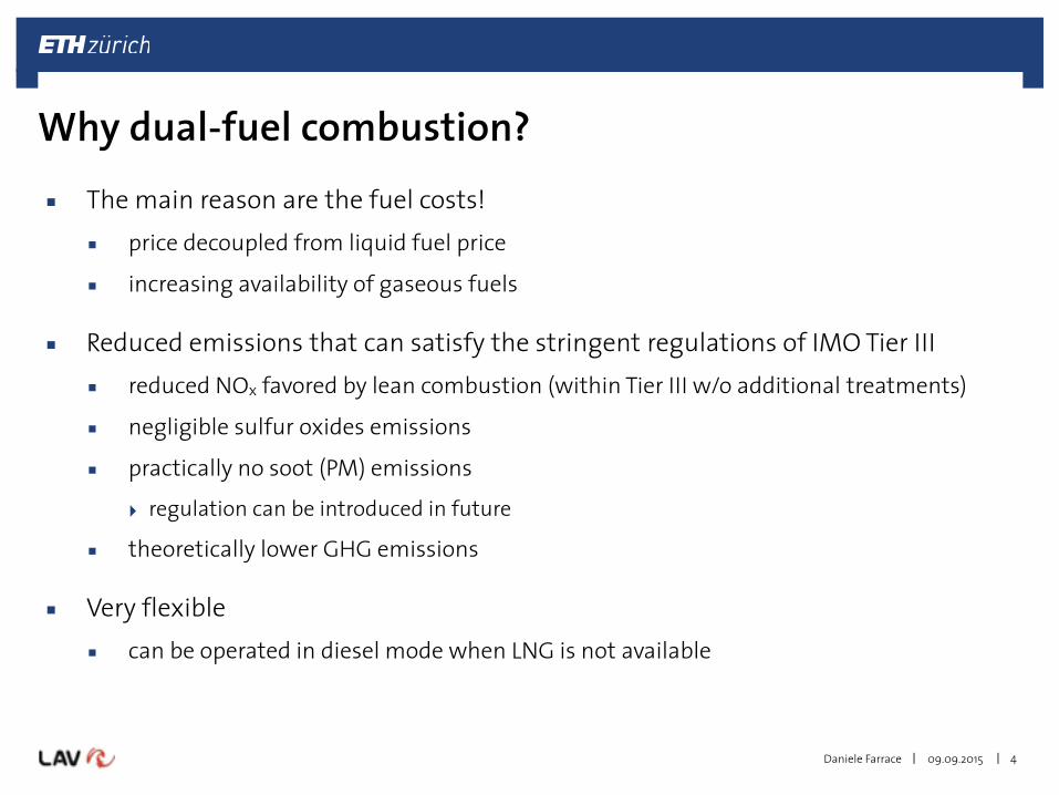
▪ The main reason are the fuel costs! ▪ price decoupled from liquid fuel price
▪ increasing availability of gaseous fuels
▪ Reduced emissions that can satisfy the stringent regulations of IMO Tier III ▪ reduced NOx favored by lean combustion (within Tier III w/o additional treatments)
▪ negligible sulfur oxides emissions
▪ practically no soot (PM) emissions
‣ regulation can be introduced in future
▪ theoretically lower GHG emissions
▪ Very flexible ▪ can be operated in diesel mode when LNG is not available
4
Why dual-fuel combustion?
|| 09.09.2015Daniele Farrace
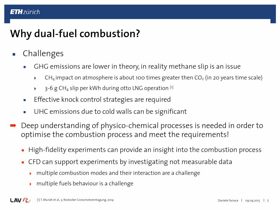
▪ Challenges ▪ GHG emissions are lower in theory, in reality methane slip is an issue
‣ CH4 impact on atmosphere is about 100 times greater then CO2 (in 20 years time scale)
‣ 3-6 g CH4 slip per kWh during otto LNG operation [1]
▪ Effective knock control strategies are required
▪ UHC emissions due to cold walls can be significant
5
Why dual-fuel combustion?
[1] T. Mundt et al., 3. Rostocker Grossmotorentagung, 2014
➡ Deep understanding of physico-chemical processes is needed in order to optimise the combustion process and meet the requirements!
▪ High-fidelity experiments can provide an insight into the combustion process
▪ CFD can support experiments by investigating not measurable data ‣ multiple combustion modes and their interaction are a challenge
‣ multiple fuels behaviour is a challenge

|| 09.09.2015Daniele Farrace 6
State-of-the-art in dual-fuel modelling▪ Knowledge of dual-fuel operation is at early stages, involved processes are not
fully understood yet…
Diesel pilotautoignition spots
flame propagation
flame kernels
▪ Autoigniting diesel spray ‣ atomization and break-up ‣ evaporation ‣ autoignition ‣ diffusion flame
▪ Regime transition ‣ premixed charge ignition ‣ flame kernels growth
▪ Turbulent premixed flame ‣ flame(s) propagation ‣ extinction
non-premixed model
premixed model
interaction

|| 09.09.2015Daniele Farrace 7
State-of-the-art in dual-fuel modelling▪ Level set approach + CTC/WM/CMC
‣ Spray ignition: CTC / Well Mixed (WM) / Conditional Moment Closure (CMC) ➡ depending on model cool flame chemistry could be considered
‣ Regime transition: flame kernel initialized when T>1200K and Rkernel>lmean
‣ Premixed flame: flame tracked by a level set method (G-equation/Weller) ➡ one-step chemistry, combustion regimes are distinguished
[1] CTC: S. Singh et al., 2005 [2] WM: Kokjohn et al., 2011 [3] CMC: S. Schlatter et al., 2011
[1][2][3]
[3]Weller 3-eqn for λCH4=1.5
!
Δt after SOI 1.7 ms 1.9 ms 2.1 ms 2.3 ms 2.5 ms
OH
dis
tribu
tion
Iso
surfa
ce b
=0.3
Weller 3-eqn for λCH4=1.5 SOI=-15°CA aTDC Percent NG= 98
[1]SOI=-15°CA aTDC
|| 09.09.2015Daniele Farrace
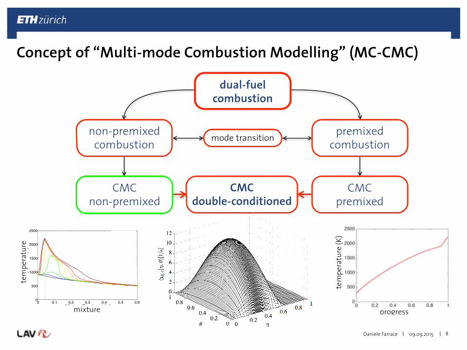
CMC double-conditioned
8
non-premixed combustion
premixed combustion
CMC premixed
tem
pera
ture
(K)
progress
CMC non-premixed
0 0.1 0.2 0.3 0.4 0.5 0.60
500
1000
1500
2000
2500
Mixture Fraction 1 [−]
Tem
pera
ture
[K]
−11.0 °CA +1.1 °CA +1.8 °CA +2.2 °CA +2.5 °CA +3.2 °CA +4.0 °CA +6.6 °CA
mixture
tem
pera
ture
mode transition
CMC non-premixed
Concept of “Multi-mode Combustion Modelling” (MC-CMC)
dual-fuel combustion

|| 09.09.2015Daniele Farrace 9
Non-premixed CMC: Work overview▪ Generic test rigs
• Aachen CVCC ✓ ignition delays, CMC physical space transport terms [1]
• ETH CVCC ✓ ignition delay/location, mech. sensitivity [2], stoch. of autoignition [3]
• Sandia CVCC ✓ ignition delays, lift-off heights [4,5], soot formation [6,7]
• ETH single stroke machine ✓ diesel pilot ignition [8]
• Marine CVCC ✓ ignition delay/location, lift-off heights [9,10]
▪ Engines • ETH Liebherr heavy-duty Diesel engine
✓ pressure [11], HRR and NOx [12], EGR [13] • Sandia heavy-duty Diesel engine
✓ HRR and soot [14], NOx [15], EGR [16], post injections [17] • ETH MTU heavy-duty Diesel engine
✓ ongoing work: NOx reduction by extreme Miller timing
Wright et al., CNF 143 (2005) [1] Wright et al., FTaC 84 (2010) [2]
Wright et al., Procs LES4ICE (2012) [3] Borghesi et al., CTM 15 (2011) [4]
Bolla et al., SAE Int. J. Engines 6 (2013) [5] Bolla et al., CST 185 (2013) [6] Bolla et al., CTM 18 (2014) [7]
Schlatter et al., Procs Dessau Conf (2011) [8] Bolla et al., Procs COMODIA (2012) [9]
Bolla et al., SAE World Congress (2014) [10]
De Paola et al., CST 180 (2008) [11] Wright et al., SAE Int. J. Engines 2 (2009) [12] Wright et al., Procs ASME ICCMSE (2010) [13]
Bolla et al., FUEL 117 (2014) [14] Farrace et al., SAE Int. J. Engines 6 (2013) [15] Farrace et al., SAE Int. J. Engines 7 (2014) [16]
Pandurangi et al., SAE Int. J. Engines 7 (2014) [17]

|| 09.09.2015Daniele Farrace 10
Non-premixed CMC: Spray Combustion Chamber (SCC)
experimentsimulation
0.25 ms 0.75 ms 1 msLiquid spray region
axial distance (mm)
Experiment Simulation
Flame evolution0.75 ms 2 ms 6 ms
d0=0.875mm 80bar 800K
d0=0.875mm 90bar 900K
[1] K. Herrmann et al., CIMAC World Congress, 2007 [2] M. Bolla et al., SAE World Congress, 2014
[1]
[1] [2]

|| 09.09.2015Daniele Farrace
CMC double-conditioned
11
non-premixed combustion
premixed combustion
CMC premixed
CMC non-premixed
mode transition
CMC non-premixed
CMC premixed
dual-fuel combustion
Concept of “Multi-mode Combustion Modelling” (MC-CMC)

|| 09.09.2015Daniele Farrace
IC engines
▪ Turbulent premixed combustion - regimes
12
Premixed combustion in real applications
(e)
(d)
(a)
(b)(c)
(a) (b) (c)
(d)
(e)
Simulation: Aspden et al., The Astrophysical Journal 689, 2008
Gas turbines
from Siemens (Workshop, Cambridge, 25th June 2015)

|| 09.09.2015Daniele Farrace 13
Premixed CMC: Model formulation
!u, !p, !k, !ε , !c, ′′c 2!,Zi!flow field
to CMCCMC
ρ ζ ∂Qα
∂t+ ρui ζ
∂Qα
∂xi+∂ ρui′′Yα ′′ ζ P! ζ( )⎡⎣⎢
⎤⎦⎥
P! ζ( )∂xi= !ωα ζ − !ω c ζ
∂Qα
∂ζ+ ρNc ζ
∂2Qα
∂ζ 2
initial conditions
ζ
T, Yα
10
Τ
CH4 O2
Nc ζ =εc! ⋅ f ζ( )f c( ) p c( )
0
1
∫ dc
tabulated in CHEMKIN
flow field
iterate until CMC convergence
get !ω c ζ Yα ζand
!ω c! = !ω c ζ P!
0
1
∫ ζ( )∂ζ
′′c !ω c! = ζ !ω c ζ P!
0
1
∫ ζ( )∂ζ
− !c ⋅ !ω c ζ P!0
1
∫ ζ( )∂ζ
Yα! = Yα ζ P!0
1
∫ ζ( )∂ζconvolution
required to CFD!ω c! and ′′c !ω c
!
linear interpolation or tabulated in CHEMKIN

|| 09.09.2015Daniele Farrace
▪ Bunsen piloted burner (from Chen et al., Combustion and Flame 107, 1996)
14
flame F1 F2 F3
U0 (m/s) 65.0 50.0 30.0Re (-) 52’000 40’000 24’000
τchem (ms) 0.44 0.44 0.44
δL (mm) 0.175 0.175 0.175
τturb (ms) 0.51 0.65 1.10
lturb (mm) 2.4 2.4 2.4
F3F2F1
Premixed CMC: Bunsen flame F2 - configuration

|| 09.09.2015Daniele Farrace
Premixed CMC: Bunsen flame F2 - results
r/D00 0.5 1 1.5 20
0.5
1
1.5X/D0=2.5
ExpCFD
0
0.5
1
1.5X/D0=4.5
0
0.5
1
1.5X/D0=6.5
0
0.5
1
1.5X/D0=8.5
U/U
0
0
0.5
1
1.5X/D0=10.5
r/D00 0.5 1 1.5 20
5
10
15X/D0=2.5
ExpCFD
0
5
10
15X/D0=4.5
0
5
10
15X/D0=6.5
0
5
10
15X/D0=8.5
k/k 0
0
5
10
15X/D0=10.5
15
▪ Cold flow (flow field validation)
X/D0=2.5X/D0=4.5X/D0=6.5X/D0=8.5X/D0=10.5
Experiment: Chen et al., Combustion and Flame 107, 1996

|| 09.09.2015Daniele Farrace
Premixed CMC: Bunsen flame F2- mechanism analysis
16
▪ Chemical mechanism considerations in view of dual-fuel ‣ Pitsch-44 (P44) contains the relevant high temperature CH4 paths
P44 GRIr/D0
0 0.5 1 1.5 20
0.5
1
1.5X/D0=2.5
ExpCFD
0
0.5
1
1.5X/D0=4.5
0
0.5
1
1.5X/D0=6.5
0
0.5
1
1.5X/D0=8.5
U/U
00
0.5
1
1.5X/D0=10.5
r/D00 0.5 1 1.5 20
5
10
15X/D0=2.5
ExpCFD
0
5
10
15X/D0=4.5
0
5
10
15X/D0=6.5
0
5
10
15X/D0=8.5
k/k 0
0
5
10
15X/D0=10.5

|| 09.09.2015Daniele Farrace
Premixed CMC: Bunsen flame F2- mechanism analysis
17
▪ Chemical mechanism considerations in view of dual-fuel ‣ Pitsch-44 (P44) contains the relevant high temperature CH4 paths
P44 GRIr/D0
0 0.5 1 1.5 20
0.5
1
1.5X/D0=2.5
ExpCFD
0
0.5
1
1.5X/D0=4.5
0
0.5
1
1.5X/D0=6.5
0
0.5
1
1.5X/D0=8.5
U/U
00
0.5
1
1.5X/D0=10.5
r/D00 0.5 1 1.5 20
5
10
15X/D0=2.5
ExpCFD
0
5
10
15X/D0=4.5
0
5
10
15X/D0=6.5
0
5
10
15X/D0=8.5
k/k 0
0
5
10
15X/D0=10.5

|| 09.09.2015Daniele Farrace
Premixed CMC: Bunsen flame F2- results
X/D0
0 2 4 6 8 10 12
δ t (mm
)
0
5
10
15
20
25 Experiment Unstrained flamelet
X/D0
0 2 4 6 8 10 12
δ t (mm
)
0
5
10
15
20
25 Experiment Unstrained flamelet CMC based on CH4 CMC based on O2
X/D0
0 2 4 6 8 10 12
δ t (mm
)
0
5
10
15
20
25 Experiment Unstrained flamelet CMC based on CH4 CMC based on O2 Strained flamelet G-equation
18
Experiment: Chen et al., Combustion and Flame 107, 1996
Progress variable0 0.1 0.2 0.3 0.4 0.5 0.6 0.7 0.8 0.9 1
dc/d
r (1/
m)
0
50
100
150
200
250
X/D=2.5 X/D=4.5 X/D=6.5 X/D=8.5 X/D=10.5
δ t =∂ !c∂r
⎛⎝⎜
⎞⎠⎟−1
max
[1] Kolla et al., Combustion and Flame 157, 2010[2] Herrmann et al., Combustion and Flame 145, 2006
1
12
▪ Turbulent flame thickness

|| 09.09.2015Daniele Farrace
CMC double-conditioned
19
non-premixed combustion
premixed combustion
dual-fuel combustion
CMC premixed
CMC non-premixed
mode transition
CMC non-premixed
CMC premixed
CMC double-conditioned
Concept of “Multi-mode Combustion Modelling” (MC-CMC)

|| 09.09.2015Daniele Farrace 20
Multi-mode CMC: model formulation
0, high Re flows
PDF gradient model (Pope 1985)AMC model (Nguyen 2010)
algebraic mean or neglectedalgebraic model (Kolla 2010)
first order closure (Bilger 2004) Bilger 1993
▪ …just to give an idea about the model complexity
‣ Boundary and initial conditions? ‣ Probability Density Function (PDF) models? Cross-PDF? ‣ etc.

|| 09.09.2015Daniele Farrace 21
Conclusions & Outlook
▪ Towards a complex formulation for multiple combustion modelling, two numerical frameworks have been first established: ‣ CMC for non-premixed combustion has been carefully validated over a
broad range of conditions showing promising results ‣ CMC for premixed combustion has been formulated and recently
implemented • A first validation work has been conducted for canonical problems • Other configurations will be simulated (spark ignited flames, real engines
geometry)
▪ Next step is the coupling of the two models for a double-conditioned CMC formulation (ongoing work) ‣ A priori DNS studies will be conducted
‣ Double-conditioned CMC will be validated with DNS data
|| 09.09.2015Daniele Farrace 22
Acknowledgments
Financial support from the
Swiss Federal Office of Energy (BfE)
and the
Swiss Competence Centre Energy and Mobility (CCEM)
is gratefully acknowledged.
The authors further thank
Prof. Mastorakos and Prof. Swaminathan (Cambridge University)
for very helpful discussions.

Thank you for your kind attention!


![Dual Fuel Gas Turbine[1]](https://img.pdfslide.net/doc/110x75/551502d84a7959d2028b511e/dual-fuel-gas-turbine1.jpg)