Embed Size (px)
Citation preview

Dual-Lite® Trident TRF Emergency Lighting Inverter
10kVA-60kVA (UL 924 System)
Recommended Guide Specification

2 | P a g e U L 9 2 4 1 0 k V A - 6 0 k V A R e c o m m e n d e d G u i d e S p e c i f i c a t i o n 0 5 - 2 3 - 2 0 1 7
SECTION 1.0
SCOPE 1.1 Summary
A. This Specification defines the electrical and mechanical characteristics and requirements for the TRIDENT TRF UL924 Series Emergency Lighting Inverter (ELI) as manufactured by Dual-Lite located in Greenville, S.C.
B. The ELI shall be a continuous duty; three-phase, uninterruptible power system, hereafter referred to as the ELI designed to operate with the building supply to provide conditioned power as well as power back up for the critical loads.
C. The UPS shall use Adaptive Feed Cancellation (AFC) Technology that provides advanced control with AFC forward cancellation circuit for low harmonic distortion.
1.2 Qualifications
The manufacturer shall have a minimum of 20 years of experience in the design, manufacture, and testing of solid-state transistorized UPS/ELI systems of similar capacity.
1.3 Standards
A. The ELI shall be designed in accordance with the applicable sections of the current revision of the following documents. Where conflict arises between these documents and statements made herein, the statements in this specification shall prevail.
1. UL 924 listed as “Emergency Lighting Equipment” and “Auxiliary Lighting and Power
Equipment”. Complies with NFPA 101 Life Safety Code. 2. NEMA PE-1 3. FCC PT 15, Subpart J, Class B 4. National Electric Code 5. OSHA 6. ANSI C62.41 7. ISO 9001 8. ASME 9. ASA-C-39.1-1984 10. IEEE 587 ANSI C 62.41-1980
1.4 System Description
A. The UPS shall be a true double conversion, “On-Line” system consisting of the following major components:
1. Rectifier complete with power factor correction 2. Battery charger 3. PWM Inverter utilizing IGBT’s (Insulated Gate Bipolar Transistor) 4. Continuous duty rated Static Switch 5. Input Isolation switch (SWIN) 6. Output Isolation switch (SWOUT) 7. Maintenance Isolation switch (SWMB) 8. Bypass Isolation switch (SWBY) 9. DSP Control and Monitoring Panel with Graphic display
Warranty
A. ELI Warranty
The ELI warranty shall be in effect for 24 months after initial start-up but no more than 30 months after shipment, whichever occurs first. The warranty shall cover all parts and labor for units commissioned by manufacturer’s approved service representative.
3 | P a g e U L 9 2 4 1 0 k V A - 6 0 k V A R e c o m m e n d e d G u i d e S p e c i f i c a t i o n 0 5 - 2 3 - 2 0 1 7
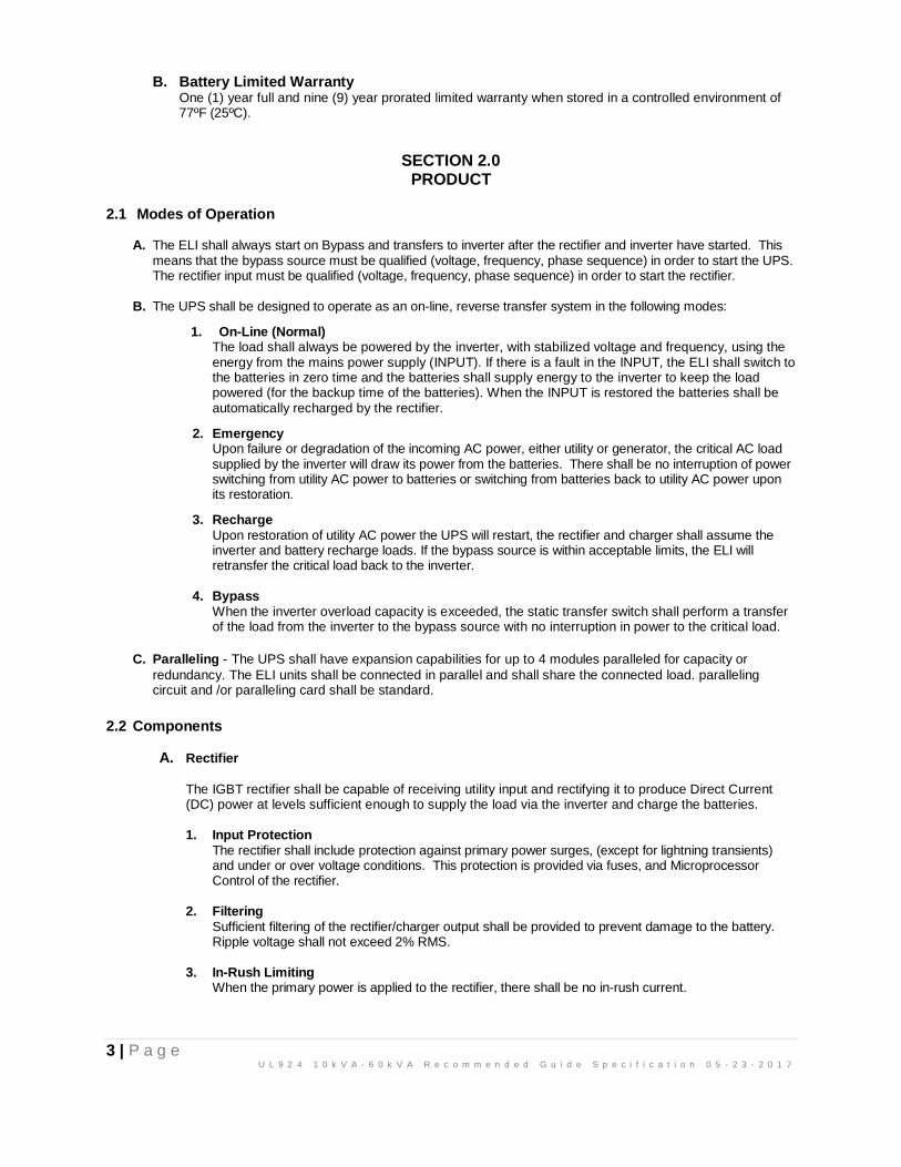
B. Battery Limited Warranty One (1) year full and nine (9) year prorated limited warranty when stored in a controlled environment of 77ºF (25ºC).
SECTION 2.0 PRODUCT
2.1 Modes of Operation
A. The ELI shall always start on Bypass and transfers to inverter after the rectifier and inverter have started. This means that the bypass source must be qualified (voltage, frequency, phase sequence) in order to start the UPS. The rectifier input must be qualified (voltage, frequency, phase sequence) in order to start the rectifier.
B. The UPS shall be designed to operate as an on-line, reverse transfer system in the following modes:
1. On-Line (Normal) The load shall always be powered by the inverter, with stabilized voltage and frequency, using the energy from the mains power supply (INPUT). If there is a fault in the INPUT, the ELI shall switch to the batteries in zero time and the batteries shall supply energy to the inverter to keep the load powered (for the backup time of the batteries). When the INPUT is restored the batteries shall be automatically recharged by the rectifier.
2. Emergency Upon failure or degradation of the incoming AC power, either utility or generator, the critical AC load supplied by the inverter will draw its power from the batteries. There shall be no interruption of power switching from utility AC power to batteries or switching from batteries back to utility AC power upon its restoration.
3. Recharge Upon restoration of utility AC power the UPS will restart, the rectifier and charger shall assume the inverter and battery recharge loads. If the bypass source is within acceptable limits, the ELI will retransfer the critical load back to the inverter.
4. Bypass When the inverter overload capacity is exceeded, the static transfer switch shall perform a transfer of the load from the inverter to the bypass source with no interruption in power to the critical load.
C. Paralleling - The UPS shall have expansion capabilities for up to 4 modules paralleled for capacity or
redundancy. The ELI units shall be connected in parallel and shall share the connected load. paralleling circuit and /or paralleling card shall be standard.
2.2 Components
A. Rectifier
The IGBT rectifier shall be capable of receiving utility input and rectifying it to produce Direct Current (DC) power at levels sufficient enough to supply the load via the inverter and charge the batteries.
1. Input Protection
The rectifier shall include protection against primary power surges, (except for lightning transients) and under or over voltage conditions. This protection is provided via fuses, and Microprocessor Control of the rectifier.
2. Filtering
Sufficient filtering of the rectifier/charger output shall be provided to prevent damage to the battery. Ripple voltage shall not exceed 2% RMS.
3. In-Rush Limiting
When the primary power is applied to the rectifier, there shall be no in-rush current.

4 | P a g e U L 9 2 4 1 0 k V A - 6 0 k V A R e c o m m e n d e d G u i d e S p e c i f i c a t i o n 0 5 - 2 3 - 2 0 1 7
4. Walk-In When the utility power is applied to the rectifier, the current shall gradually increase. Walk-in from 25% max to 100% full load rating in 5 seconds
5. Automatic Restart
Upon restoration of utility AC power after a power outage, the rectifier shall automatically restart and resume the inverter and battery recharge loads. Functional only on units with batteries.
6. Charger An integral charging circuit shall be capable of recharging the batteries during normal operation to ensure maximum life from the battery system.
7. Charger Capacity
The charger shall have sufficient capacity to recharge a fully discharged battery to 90% capacity within ten times discharge time.
8. Battery Test The UPS shall periodically check the battery system for an open cell. If the ELI detects an open cell, an alarm condition shall be displayed and an audible alarm shall sound.
B. Inverter The inverter section of the power converter module shall utilize Insulated Gate Bipolar Transistors (IGBT's). This solid-state device that incorporates digital signal processing (DSP) pulse width modulation (PWM) technology capable of accepting the output of the rectifier or the battery system voltage and delivering AC power within specified limits to the critical load bus. The inverter shall be microprocessor controlled and include all necessary timing logic and control circuits.
C. Inverter Start-Up The inverter shall automatically startup when a start command is generated and shall be stable and
ready to deliver power to the load.
1. Inverter Protection Inverter IGBT's shall be protected by current limiting circuits. The inverter shall be capable of
running indefinitely with the batteries disconnected. For rapid removal of the inverter from the critical load, the inverter’s control electronics shall instantaneously turn off the inverter when the inverter’s capacity is exceeded. Simultaneously, the static transfer switch shall transfer the load to utility power without interruption to maintain continuous power to the critical load.
2. Inverter Oscillator The inverter shall contain an oscillator capable of operating and maintaining the output frequency of
the inverter within specified limits. The inverter oscillator shall be capable of frequency synchronization and phase locking to the bypass utility power source frequency. When operating as a slave to the utility power and a failure occurs in the slaving signal, the inverter oscillator shall automatically revert to a free running state and maintain the specified limits. The oscillator shall not drift more than 0.05% while operating at maximum rated operating temperature.
3. Phase Balance Electronic controls shall be provided to regulate each phase so that an unbalanced load will not
cause the output voltage to go outside of the specified voltage unbalance or phase displacement limits.
D. Static Transfer Switch – 100% Rated, Continuous Duty An internally mounted static transfer switch and bypass circuit shall be provided as an integral part of the UPS. The static switch shall be naturally commutated high speed devices rated to conduct full load current continuously while on bypass power. The static switch shall be designed to avoid back-feed into the utility supply. Failure of one device shall not affect the operation of the ELI and the failure shall be shown on the LCD display.

5 | P a g e U L 9 2 4 1 0 k V A - 6 0 k V A R e c o m m e n d e d G u i d e S p e c i f i c a t i o n 0 5 - 2 3 - 2 0 1 7
1. Bypass Transfer The static switch shall automatically and successfully transfer the critical load from the inverter to
the bypass source under the following conditions:
• DC voltage out-of-limits
• Inverter failure
• Critical load current exceeds inverter overload rating
• Over-temperature develops within the inverter
• Manual command is given
Transfer shall be automatically inhibited whenever bypass source parameters are outside predetermined (adjustable) limits, or ELI output and bypass are not synchronized and phase locked.
2. Retransfer The static switch shall automatically and successfully retransfer the critical load from the bypass source to the inverter under the following conditions:
• Inverter output voltage returns to within specified limits.
• Critical load current reduces to within inverter limits.
E. Battery
1. General The ELI module shall use a valve-regulated sealed lead acid (VRLA) heavy duty industrial battery, designed for auxiliary power service in an ELI application. The primary battery shall be furnished with impact-resistant plastic cases and housed in matching cabinet(s) installed both adjacent to or standalone versions.
2. Protection against Deep Discharge and Self-Discharge The ELI shall be equipped with a device designed to protect the battery against deep discharge, depending on discharge conditions, with isolation of the battery by a circuit breaker. In particular, a monitoring device shall adjust the battery shutdown voltage as a function of a discharge coefficient to avoid excessive discharge at less than the rated output.
3. Battery Self-Tests The ELI shall periodically test the batteries. Should the ELI determine that the batteries would not sufficiently support the load an alarm shall be indicated.
Manual Internal Maintenance Bypass Bypass switching shall allow the critical load to be fed from the bypass power source, while providing isolation of the static switch during maintenance.
2.3 Electrical Specifications
A. Ratings
1. The UPS shall be available in power ratings of (kVA/kW): 10kVA/9kW 15kVA/13.5kW 20kVA/18kW 30kVA/27kW 40VA/36kW 50kVA/45kW 60kVA/54kW
2. The Minimum battery time @ Full Load shall be 90 Minutes.
3. AC Input Characteristics
The UPS shall be capable of accepting power from two (2) sources as standard (Dual Input).
a. Nominal Voltage: 208Y/120 VAC, 3 Phase, 4-wire + ground (Standard Voltage),
or
220/127 VAC configurable from the Front Panel
or

6 | P a g e U L 9 2 4 1 0 k V A - 6 0 k V A R e c o m m e n d e d G u i d e S p e c i f i c a t i o n 0 5 - 2 3 - 2 0 1 7
480Y/277 VAC, 3 Phase, 4-wire + ground - with external cabinet with K20 – Shielded transformer cabinet (Optional)
b. Nominal Voltage Range: +15/-20% (Battery discharge at -15% at full load). d. Frequency: 50/60Hz, +/- 5.0Hz e. Power Factor: > 0.99 at full load, 0.98 minimum at 50% load. f. Current Harmonic Distortion (THDi): < 1% at full load, <2% at 50% load and <5% at 10% load.
g. Inrush current: Less than nominal input current for less than one cycle. h. Input Surge Protection: UPS shall be equipped to withstand surges per ANSI/IEEE C62.41.
i. Rectifier Walk-in: Input current shall ramp up from 25% to 100% over 5 seconds.
4. AC Output Characteristics
a. Voltage: 208Y/120 VAC, ± 2% steady state variation phase-to-phase voltage volts AC, three-phase, 4-wire plus ground (Standard Voltage).
or
220/127VAC configurable from the Front Panel
or
480Y/277 VAC, 3 Phase, 4-wire + ground –with external cabinet with K20 – Shielded transformer cabinet (Optional)
b. Frequency: 60/50Hz, ±0.5%, 1.0%, 2.0%, 5.0% User settable, 60Hz, ± 0.01Hz when free running.
c. Voltage regulation: ±2% for balanced load. d. Voltage Distortion: <1% with balanced loads, 2% with unbalanced loads (THD). e. Voltage Transient (Step Load) Response: a) +/- 15% at the first cycle for a 100% step load b)
+/- 1% (loss or return of AC input)
f. Voltage Recovery Time: Return to within 1% of nominal value within 10 milliseconds.
g. Phase Angle Displacement: 120 degrees + /- 1º for balanced load; 120º, +/- 1º for 100% unbalanced load.
h. Non-Linear Load Capability: Output voltage total harmonic distortion shall be less than 1% when connected to a 100% non-linear load with a crest factor not to exceed 3%.
i. Slew Rate: ±10 hertz per second.
j. Power Factor: 0.9 at the rated volt amperes (VA).
k. Inverter Overload Capability: 125% of rated load for 10 minutes, 150% of rated load for 60 seconds.
l. Bypass Overload Capability: 400% for 10 seconds, 1000% for ½ cycle.
m. Output Waveform: Sinusoidal.
n. Efficiency: Up to 90% at Full Load.
5. Battery
a. Battery Voltage: 432 volts DC nominal, 486VDC float. .

7 | P a g e U L 9 2 4 1 0 k V A - 6 0 k V A R e c o m m e n d e d G u i d e S p e c i f i c a t i o n 0 5 - 2 3 - 2 0 1 7
2.4 Mechanical Design and Ventilation
A. Enclosure: The ELI shall be housed in a freestanding NEMA 1 enclosure with dead front construction. The mechanical structure of the ELI shall be sufficiently strong and rigid to withstand handling and installation operations without risk and have provisions for forklift handling. The sheet metal elements in the structure shall be protected against corrosion by a suitable treatment, primed and powder coat painted black with a textured finish.
B. Redundant, forced air-cooling shall be provided to ensure that all components are operated within specification with air entry at the front with rear air exit.
C. Cable Access: The standard ELI shall accommodate bottom entry cables.
D. Clearance – 3” rear.
E. Ventilation and Heat Rejection: The ELI shall be designed for forced air cooling. Air inlets shall be provided from the front and bottom of the ELI enclosure. Air exhaust shall be from the rear of the unit. Full load heat rejection shall be 2,400 BTU/hr at 9kW, 3,500 BTU/hr at 13.5kW, 4,700 BTU/hr at 18kW, 7,000 BTU/hr at 27kW and 9,300 BTU/hr 36kW, 21,000 BTU/hr at 45kW and 18,300 BTU/hr at 54kW.
2.5 Environmental Requirements
A. The System shall withstand any combination of the following external environmental conditions without operational degradation.
1. Operating Temperature Range: 32ºF (0ºC) to 104ºF (40ºC) for the electronics, however the batteries should not be exposed to prolonged periods of temperature above 77ºF (25ºC). For every 15ºF (8ºC) above 77ºF battery life is cut in half, and may void the battery warranty.
2. Storage Temperature Range: -25ºF (-32ºC) to 122ºF (50ºC) however batteries should not be exposed to
temperatures above 77ºF (25ºC). For every 15ºF (9.5ºC) above 77ºF battery life is cut in half, and may void the battery warranty.
3. Relative Humidity: Continuous operation with a relative humidity up to 90% non-condensing at 77°F (25°C).
4. Altitude: Normal operation without de-rating is 3,281 feet.
5. Audible Noise: Audible noise generated by the ELI shall not exceed 61 dBA for 9kW-18kW units and <75 dBA for 27kW-54kW units when measured at 1 meter in front of the power converter using scale “A” of a standard ASA sound level-measuring device.
2.6 System Controls and Indicators
The ELI unit shall incorporate the necessary controls, instruments and indicators to allow the operator to monitor the system status and performance, as well as take any appropriate action. The ELI Control and Display shall have (3) sections.
LED Indicators Graphic Display Keyboard/Navigation LED Indicators for:
• Rectifier Input Voltage OK – Green
• Unit on Bypass – Orange
• Inverter working – Green
• Unit on Battery/Main Failure – Red
• Alarm Activated – Red
Graphic Display A main display 3.5” H x 4.58” W screen shall be provided to display the ELI measurements and for consulting the various menus which the user shall select using the designated function keys.

8 | P a g e U L 9 2 4 1 0 k V A - 6 0 k V A R e c o m m e n d e d G u i d e S p e c i f i c a t i o n 0 5 - 2 3 - 2 0 1 7
Keyboard/Navigation Area with (6) function keys to navigate through menu screens which is active. The display shall indicate the function belonging to the corresponding key in the appropriate box, access main menu, go back to previous menu or display, scroll, confirm selection and silence function keys. The UPS shall have buttons allowing the user to scroll through the display menus provided by the graphic display.
ENT «Enter» key. Confirmation of orders, program values. «Left» key for submenu navigation, or cursor displacement.«Right» key for submenu navigation, or cursor displacement. «Up» key for menu navigation, or digit modification. «Down» key menu navigation, or digit modification. ESC «Escape» key. Return to main screen, cancel/finish programming. ENT, When pressed simultaneously at least during 3 seconds, equivalent to an Emergency Power Off (EPO), turn-off any voltage at the output.
A. Graphic Display
A graphical screen display shall be on the ELI door, which provides the user to have a close-up, detailed overview in real time of the status of the ELI. The user shall be able to switch the ELI on and off, consult electrical mains, output, battery measurements, and perform the main ELI settings. This display shall also incorporate a mimic diagram showing the current operating status of the ELI.
B. Menu Display Screens
• Main Level Screen 0.0 o Time and Date
• System Control and Status o Start and Stop Screen 1.1 and 1.2 o Select Battery Test (Screen 1.3)
▪ Not Available ▪ Battery Test Running ▪ Battery Test Successful ▪ Battery Test Failed
• Measure Screen 2.1 o Input Apparent Power of L1 o Input Apparent Power of L2 o Input Apparent Power of L3 o Input Active Power of L1 o Input Active Power of L2 o Input Active Power of L3 o Total input Apparent Power and Active Power o Input Power Factor (each phase) o Input, Bypass and Output Frequencies o Rectifier, Inverter and Battery Temperature
• Measure Screen 2.2 o Inverter Output Voltages Phases to Neutral o Inverter Output Current per each Phase o Bypass Voltages Phases to Neutral o Bypass Current per each Phase o Charge Battery Currents o Discharge Battery Currents
• Measure Screen 2.3 o Input Apparent Power of L1 o Input Apparent Power of L2 o Input Apparent Power of L3

9 | P a g e U L 9 2 4 1 0 k V A - 6 0 k V A R e c o m m e n d e d G u i d e S p e c i f i c a t i o n 0 5 - 2 3 - 2 0 1 7
o Input Active Power of L1 o Input Active Power of L2 o Input Active Power of L3 o Total input Apparent Power and Active Power o Input Power Factor (each phase) o Input, Bypass and Output Frequencies o Rectifier, Inverter and Battery Temperature
• Measure Screen 2.4 o Output Apparent Power of L1 o Output Apparent Power of L2 o Output Apparent Power of L3 o Output Active Power of L1 o Output Active Power of L2 o Output Active Power of L3 o Total Output Apparent Power and Active Power o Output Power Factor (each phase) o Output Load of Three Phases o Total Input Load and Total Output Load o Estimated Battery Time
• Settings Screen 3.0 o Basic Settings
▪ Time and Date ▪ Language ▪ Modbus Address ▪ Program Service Contact Information ▪ Baud Rate ▪ Parity Type of COM Port ▪ Number of Stop Bits ▪ Protocol Type of COM Port ▪ Battery Test Schedule – Disable, Weekly, Monthly, Yearly ▪ Battery Test Schedule – Select Day of the Week
o Advanced Settings Screen 3.4
▪ Set Password ▪ Set Rated Values
• Input Voltage
• Output Voltage
• Input Voltage Minimum Margin %
• Input Voltage Maximum Margin %
• Bypass Voltage Minimum Margin %
• Bypass Voltage Maximum Margin %
• DC Bus Voltage
• Output Current
• Battery Charging Current
• Battery Probe
• AC Current Probe
o Information Screen 3.6 ▪ LCD Version ▪ DSP Version ▪ Serial Number ▪ Service Phone Number ▪ Service Email Address ▪ Service Contact Address
• Alarms Screen 3.5 o 77 Alarms Identified
• Data Logger Screen 3.6 o hour of alarm activation

10 | P a g e U L 9 2 4 1 0 k V A - 6 0 k V A R e c o m m e n d e d G u i d e S p e c i f i c a t i o n 0 5 - 2 3 - 2 0 1 7
o minutes of alarm activation o seconds of alarm activation o day of alarm activation o month of alarm activation o year of alarm activation o hour of deleted alarm o minutes of deleted alarm o seconds of deleted alarm o day of deleted alarm o month of deleted alarm o year of deleted alarm
C. Communications (Standard)
The ELI shall have the ability to communicate through the following options:
1. SNMP: Internal SNMP Card shall be standard on all ELI’s to allow ELI management across a LAN using any of the main network communication protocols - TCP/IP, HTTP and network interface (SNMP). ViewPower Pro shutdown/monitoring software shall enable the UPS to integrate easily into medium and large sized networks and provide reliable communications between the ELI and management systems employed.
2. Modbus: Internal MODBUS/JBUS Card, Protocol converter shall be standard and used to monitor the ELI using the MODBUS/JBUS protocol on RS232 or RS485 serial lines. It shall also manage a second independent RS232 serial line that can be used to connect to other devices such as the SNMP.
3. Relay Interface: Four voltage free relays with no common point shall be provided through a sub-D9 connector. Consisting of 4 output signaling relays
a. Battery Discharge (NO or NC) b. Unit on Bypass c. Low Battery d. General alarm
2.6.1 Com Port to Relay
The communication port to relays provides digital signals in the form of potential free contacts with a maximum applicable voltage and current of 6 A 30 V DC or 6 A 100 V AC. Both channels are in use for connecting the ELI with any machine or devices that has this standard bus (connector DB9).
˙ It shall consists of 5 output signaling relays (one of which is configurable), whose common point is connected to pin 5. Also an input signal can be externally supplied to perform Shutdown (5V~12V).
2.6.2 Com Port RS-232 & RS-485
In the same connector DB9 there shall be both ports of communication of the equipment, the RS-232 and the RS-485, they cannot be simultaneously used as mutually exclusive.
˙ Both channels are in use for connecting the ELI with any machine or devices that has this standard bus. The RS-232 consists of the transmission of serial data, so it is possible to send a large amount of information through a communication cable of just 3 wires.
2.6.2.A Communication protocol of the RS-232 The communication protocol used is of MASTER/SLAVE type. The computer or computer system (MASTER) asks about a certain data, and the ELI (SLAVE) answers immediately with the required data.
Firstly it will be programmed by the communication channel of the computer with the same parameters as the communication channel of the ELI. Then we will be prepared to start the communication and therefore send the UPS the first question.
2.6.2.B Physical structure of the RS-485.
Unlike other serial communication links, this uses only 2 wires (pins 4 and 9 of the female DB9 connector) to perform the dialogue between the systems

11 | P a g e U L 9 2 4 1 0 k V A - 6 0 k V A R e c o m m e n d e d G u i d e S p e c i f i c a t i o n 0 5 - 2 3 - 2 0 1 7
connected to the network. The communication will be established by sending and receiving signals in differential mode, which gives the system great immunity to noise and a long reach (approx. 2,635 ft. (800 m).
4. Remote Emergency Power Off (EPO): The ELI shall be equipped with provisions for local and remote emergency power off that shall be used to command UPS shutdown remotely.
2.7 Parallel Configuration
The ELI shall have expansion capabilities for up to 4 modules (same rating) in a parallel configuration for capacity or redundancy as required both to support future growth and to increase the reliability of the load. The ELI units shall be connected in parallel and shall share the connected load. The parallel card/circuit shall be standard without any field modification or added parts.
2.8 Options
A. Input / Output Transformer Cabinet with/without External System Maintenance Bypass (Make-Before-Break) The ELI shall have provisions to accept an input power source of other than 208Y/120 VAC and /or output of 208Y/120VAC with the addition an external cabinet. As an integral part of the cabinet, it shall also accept a three (3) Breaker System Maintenance Bypass with interlocks and top cable entry capability.
B. External System Maintenance Bypass
An External Maintenance Bypass (make-before-break) shall be available. The total enclosure shall provide a wrap-around bypass configuration for total ELI isolation during maintenance or removal of the ELI. Maintenance bypass transfers shall be without interruption and shall have interlocks to protect the UPS from damage in the event of out-of-sequence transfers. 9kW to 27kW shall be Wall Mount and the 36kW shall be a matching Floor Mount.
C. Power Distribution Unit (PDU)
A Transformerless 208Y/120VAC PDU shall be available. It shall consist of (1) 42 Pole 225 Amp Panel board with Main, type Sq. D NQ442L2. Accepts 1, 2 & 3 Pole Branch Circuit Breakers bolt-on or plug-in in a Matching Cabinet.
D. Remote Alarm/Annunciator Panel
1. Unit on Battery 2. Low Battery 3. Unit on Bypass 4. User Specified Alarm Unit shall have a Silence/Reset Button
E. Harsh Environment Enclosure
The ELI and any accessory cabinet(s) shall have the capability to be mounted and completely wired internal to, include AC cooling, inside any NEMA type enclosure (NEMA 12, 3R, 4X) by the manufacturer.
F. Spare Parts
Shall be available in three levels, Level 1- Minor, Level 2 - Medium and Level 3 - Major.
G. Service Agreements
Multi-level service and maintenance agreements shall be available.
12 | P a g e U L 9 2 4 1 0 k V A - 6 0 k V A R e c o m m e n d e d G u i d e S p e c i f i c a t i o n 0 5 - 2 3 - 2 0 1 7
SECTION 3.0 EXECUTION
3.1 Factory Testing
Before shipment, the manufacturer shall fully and completely test the system to factory standards to assure compliance with the specification. Each subassembly shall undergo thorough testing prior to installation in the system. The total system shall be exposed to a functional load test and shall be subjected to a minimum of 24 hours "burn-in" test prior to shipment.
A complete test report shall be available for each unit and kept on file for future reference.
3.2 Site Start-Up
Site start-up and testing shall be provided by the manufacturer's field service representative during normal working hours (M/F-8/5). Individual scheduling requirements shall be met with ten working days advance notice. Site testing shall consist of a complete test of the ELI and accessories by the ELI manufacturer in accordance with manufacturer's standards. Commissioning must be performed by manufacturer’s approved service representative for warranty to apply.
3.3 Field Engineering Support
The ELI manufacturer shall have available a nationwide field service organization staffed by factory trained Field Service Engineers dedicated to the start-up, maintenance and repair of UPS equipment. The manufacturer shall have a toll free service telephone number answered 24 hours a day / 365 days a year

13 | P a g e U L 9 2 4 1 0 k V A - 6 0 k V A R e c o m m e n d e d G u i d e S p e c i f i c a t i o n 0 5 - 2 3 - 2 0 1 7
For technical assistance, contact Dual-Lite’s Technical Support Center at 1-800-848-6439. Technicians are available during normal working hours (EST).
Hubbell Lighting, Inc 701 Millennium Blvd
Greenville, SC 29607 Web site: www.dual-lite.com/

14 | P a g e U L 9 2 4 1 0 k V A - 6 0 k V A R e c o m m e n d e d G u i d e S p e c i f i c a t i o n 0 5 - 2 3 - 2 0 1 7
Thank you for choosing our product.